Delaware Training Academy Precast Box Culvert Installation ...
13
1 Delaware Training Academy Aimee Connerton, Rinker Materials Phone 301-357-0324 [email protected] Precast Box Culvert Installation Procedures AGENDA BOX CULVERT DESIGN SUBMITTAL PROCESS MANUFACTURING PROCESS INSTALLATION OF A PRECAST BOX CULVERT BOX CULVERT APPLICATIONS/FEATURES INSTALLATION METHODS Trench Embankment Tunnel Bedding - Leveling Course (4” normal -4” to 6” rocky) Foundation Compacted Fill Material Final Backfill Trench Terminology 3’ Minimum Cover for Construction Loading 0’ Minimum Cover for Design Loading Bedding - Leveling Course A bedding thickness of no less than 4 inches. If foundation is rock bedding should be a minimum of 6”. RCBs are designed for installed conditions not test conditions. Bedding should have a uniform flat surface. Coarse bedding materials are not beneficial due to irregular/sharp angles. Bedding width should equal the width of the box and the length of the box. This protects the box culvert during installation from impact damage. Should be placed in uniform layers along sides/over top of box sections. Should NOT contain debris, organic matter, frozen material or large stones. Placed and compacted to prevent settlement at the surface. Compaction and equipment loads should not exceed design strength. Compacted Fill Material Trench Terminology ASTM C850 AASHTO M273 AASHTO M259 ASTM C1433 ASTM C1577 ASTM/AASHTO STANDARDS FOR RCB ASTM C789 Welded wire fabric 65,000 psi Concrete 5,000 psi
Transcript of Delaware Training Academy Precast Box Culvert Installation ...
1
DelawareTraining Academy
Aimee Connerton, Rinker MaterialsPhone 301-357-0324
Precast Box Culvert Installation Procedures
AGENDA BOX CULVERT DESIGN
SUBMITTAL PROCESS
MANUFACTURING PROCESS
INSTALLATION OF A PRECAST BOX CULVERT
BOX CULVERT APPLICATIONS/FEATURES
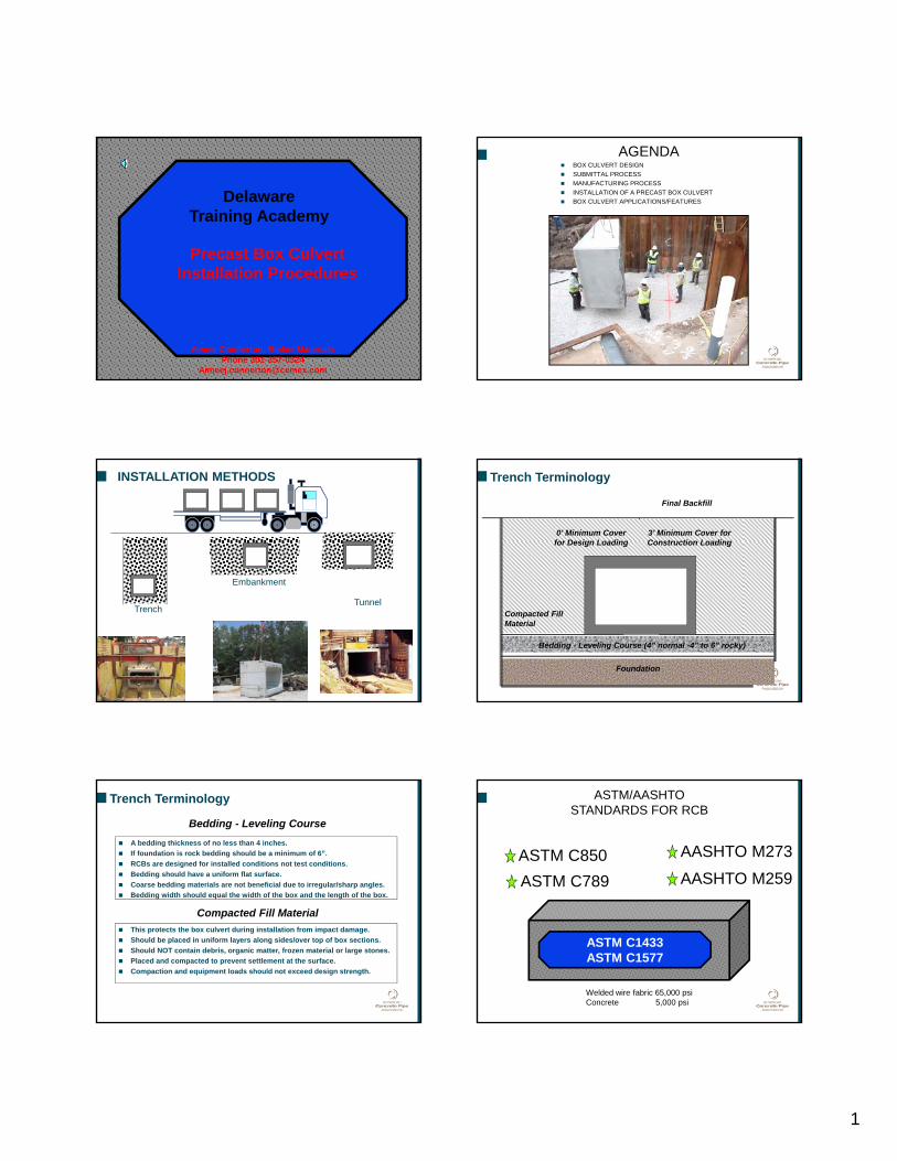
INSTALLATION METHODS
Trench
Embankment
Tunnel
Bedding - Leveling Course (4” normal -4” to 6” rocky)
Foundation
Compacted Fill Material
Final Backfill
Trench Terminology
3’ Minimum Cover for Construction Loading
0’ Minimum Cover for Design Loading
Bedding - Leveling Course
A bedding thickness of no less than 4 inches.
If foundation is rock bedding should be a minimum of 6”.
RCBs are designed for installed conditions not test conditions.
Bedding should have a uniform flat surface.
Coarse bedding materials are not beneficial due to irregular/sharp angles.
Bedding width should equal the width of the box and the length of the box.
This protects the box culvert during installation from impact damage.
Should be placed in uniform layers along sides/over top of box sections.
Should NOT contain debris, organic matter, frozen material or large stones.
Placed and compacted to prevent settlement at the surface.
Compaction and equipment loads should not exceed design strength.
Compacted Fill Material
Trench Terminology
ASTM C850 AASHTO M273
AASHTO M259
ASTM C1433ASTM C1577
ASTM/AASHTO STANDARDS FOR RCB
ASTM C789
Welded wire fabric 65,000 psiConcrete 5,000 psi
2
``````
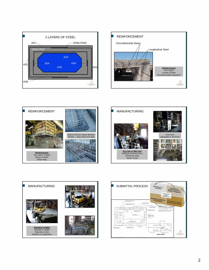
AS7 AS6(LONG)
AS2
AS5(LONG)
AS4
AS3
AS8
AS1
AS4AS1
2 LAYERS OF STEEL
Longitudinal Steel
Circumferential Steel
ReinforcementTwo Layers
8 Areas of SteelCircumferential/Longitudinal
REINFORCEMENT
REINFORCEMENT
ReinforcementTwo Layers of Steel
Sheets of WWFRebar Mats
Spacers-Ensure Space BetweenWheels – Keep Steel from Wall
MANUFACTURING
Dry Cast or Wet Cast5,000 psi concrete (min.)
65,000 psi steelSteam Cured
One FormAdjustable or Set Form
MANUFACTURING
Standard LengthsTypically 8’ LengthDepends on Size
Depends on Application
SUBMITTAL PROCESS
3
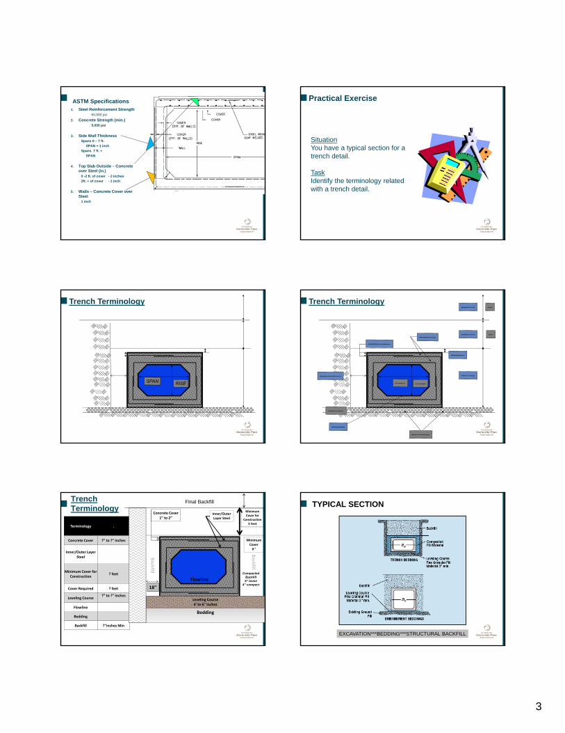
ASTM Specifications1. Steel Reinforcement Strength
65,000 psi
2. Concrete Strength (min.)5,000 psi
3. Side Wall ThicknessSpans 0 – 7 ft.
SPAN + 1 inch
Spans 7 ft. +
SPAN
4. Top Slab Outside – Concrete over Steel (in.)
0 -2 ft. of cover - 2 inches
2ft. + of cover - 1 inch
5. Walls – Concrete Cover over Steel
1 inch
SituationYou have a typical section for a trench detail.
TaskIdentify the terminology related with a trench detail.
Practical Exercise
``````
Trench Terminology
``````
Trench Terminology
18"
Trench Terminology
Terminology .
Concrete Cover ?" to ?" inches
Inner/Outer Layer Steel
Minimum Cover for Construction
? feet
Cover Required ? feet
Leveling Course?” to ?" inches
Flowline
Bedding
Backfill ?"inches Min
``````
Leveling Course4' to 6" inches
Bedding
Concrete Cover1” to 2”
Inner/Outer Layer Steel
Minimum Cover for
Construction 3 Feet
Flowline
Backfill
Backfill
Minimum Cover 0 ‘
Compacted Backfill 6” loose
4” compact
Final Backfill TYPICAL SECTION
EXCAVATION***BEDDING***STRUCTURAL BACKFILL
4
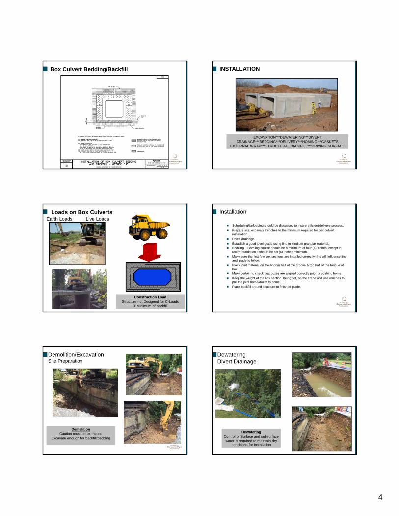
Box Culvert Bedding/Backfill
VDOT
INSTALLATION
EXCAVATION***DEWATERING***DIVERT DRAINAGE***BEDDING***DELIVERY***HOMING***GASKETS
EXTERNAL WRAP***STRUCTURAL BACKFILL***DRIVING SURFACE
Earth Loads Live LoadsLoads on Box Culverts
``````
Construction LoadStructure not Designed for C-Loads
3’ Minimum of backfill
Installation
Scheduling/Unloading should be discussed to insure efficient delivery process.
Prepare site, excavate trenches to the minimum required for box culvert installation.
Divert drainage.
Establish a good level grade using fine to medium granular material.
Bedding – Leveling course should be a minimum of four (4) inches, except in rocky foundation it should be six (6) inches minimum.
Make sure the first few box sections are installed correctly, this will influence line and grade to follow.
Place joint material on the bottom half of the groove & top half of the tongue of box.
Make certain to check that boxes are aligned correctly prior to pushing home.
Keep the weight of the box section, being set, on the crane and use winches to pull the joint home/dozer to home.
Place backfill around structure to finished grade.
DemolitionCaution must be exercised
Excavate enough for backfill/bedding
Demolition/ExcavationSite Preparation
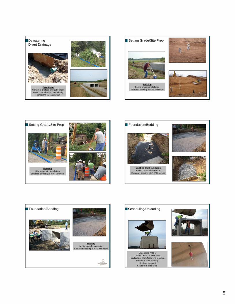
DewateringControl of Surface and subsurface water is required to maintain dry
conditions for installation
DewateringDivert Drainage
5
DewateringDivert Drainage
DewateringControl of Surface and subsurface water is required to maintain dry
conditions for installation
Setting Grade/Site Prep
BeddingKey to smooth installation
Establish bedding at 4”-6” Minimum
BeddingKey to smooth installation
Establish bedding at 4”-6” Minimum
Setting Grade/Site Prep Foundation/Bedding
Bedding and FoundationKey to smooth installation
Establish bedding at 4”-6” Minimum
Foundation/Bedding
BeddingKey to smooth installation
Establish bedding at 4”-6” Minimum
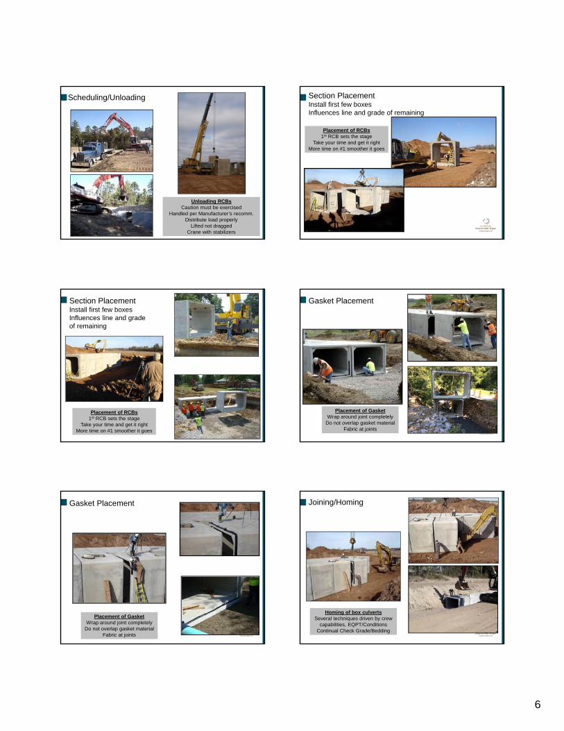
Unloading RCBsCaution must be exercised
Handled per Manufacturer’s recomm.Distribute load properly
Lifted not draggedCrane with stabilizers
Scheduling/Unloading
6
Scheduling/Unloading
Unloading RCBsCaution must be exercised
Handled per Manufacturer’s recomm.Distribute load properly
Lifted not draggedCrane with stabilizers
Section PlacementInstall first few boxesInfluences line and grade of remaining
Placement of RCBs1st RCB sets the stage
Take your time and get it rightMore time on #1 smoother it goes
Section PlacementInstall first few boxesInfluences line and grade of remaining
Placement of RCBs1st RCB sets the stage
Take your time and get it rightMore time on #1 smoother it goes
Placement of GasketWrap around joint completely
Do not overlap gasket materialFabric at joints
Gasket Placement
Placement of GasketWrap around joint completely
Do not overlap gasket materialFabric at joints
Gasket Placement
Homing of box culvertsSeveral techniques driven by crew
capabilities, EQPT/ConditionsContinual Check Grade/Bedding
Joining/Homing
7
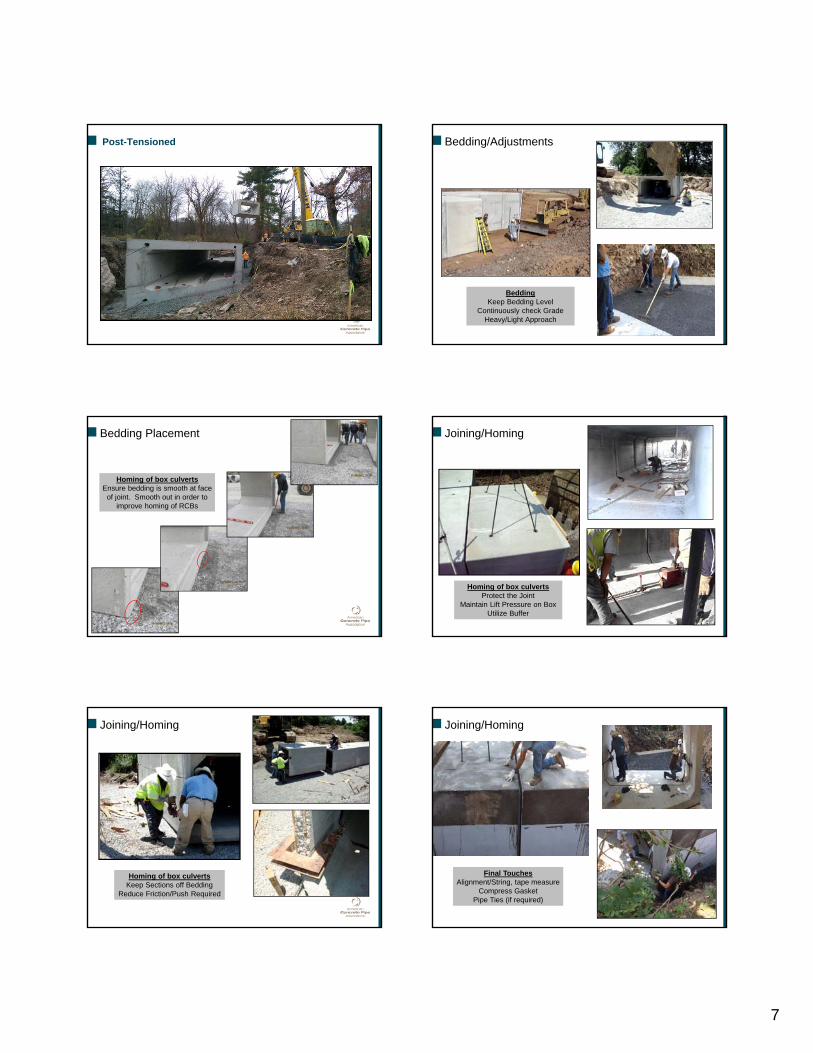
Post-Tensioned
BeddingKeep Bedding Level
Continuously check GradeHeavy/Light Approach
Bedding/Adjustments
Homing of box culvertsEnsure bedding is smooth at face
of joint. Smooth out in order to improve homing of RCBs
Bedding Placement
Homing of box culvertsProtect the Joint
Maintain Lift Pressure on BoxUtilize Buffer
Joining/Homing
Homing of box culvertsKeep Sections off Bedding
Reduce Friction/Push Required
Joining/Homing
Final TouchesAlignment/String, tape measure
Compress GasketPipe Ties (if required)
Joining/Homing
8
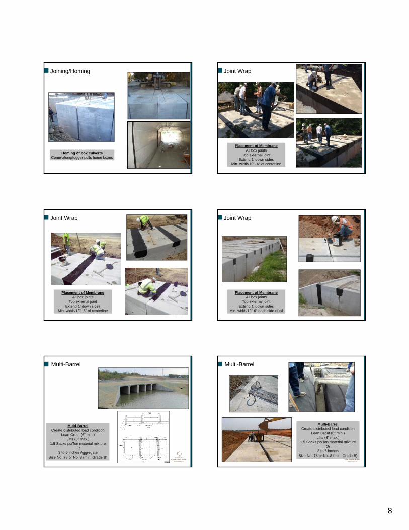
Homing of box culvertsCome-along/tugger pulls home boxes
Joining/Homing
Placement of MembraneAll box joints
Top external jointExtend 1’ down sides
Min. width/12”- 6” of centerline
Joint Wrap
Placement of MembraneAll box joints
Top external jointExtend 1’ down sides
Min. width/12”- 6” of centerline
Joint Wrap
Placement of MembraneAll box joints
Top external jointExtend 1’ down sides
Min. width/12”-6” each side of c/l
Joint Wrap
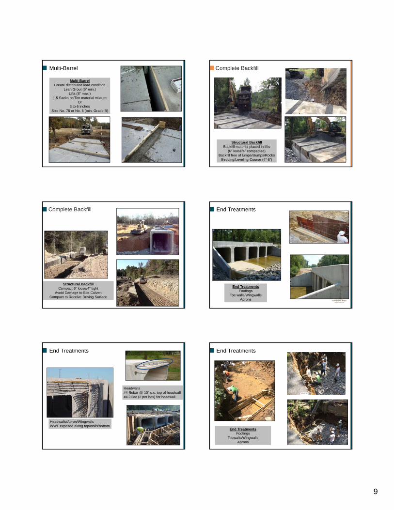
Multi-BarrelCreate distributed load condition
Lean Grout (6” min.)Lifts (8” max.)
1.5 Sacks pc/Ton material mixtureOr
3 to 6 inches AggregateSize No. 78 or No. 8 (min. Grade B)
Multi-Barrel
Multi-BarrelCreate distributed load condition
Lean Grout (6” min.)Lifts (8” max.)
1.5 Sacks pc/Ton material mixtureOr
3 to 6 inchesSize No. 78 or No. 8 (min. Grade B)
Multi-Barrel
9
Multi-BarrelCreate distributed load condition
Lean Grout (6” min.)Lifts (8” max.)
1.5 Sacks pc/Ton material mixtureOr
3 to 6 inchesSize No. 78 or No. 8 (min. Grade B)
Multi-Barrel Complete Backfill
Structural BackfillBackfill material placed in lifts
(6” loose/4” compacted)Backfill free of lumps/stumps/Rocks
Bedding/Leveling Course (4”-6”)
Structural BackfillCompact 6” loose/4” tight
Avoid Damage to Box CulvertCompact to Receive Driving Surface
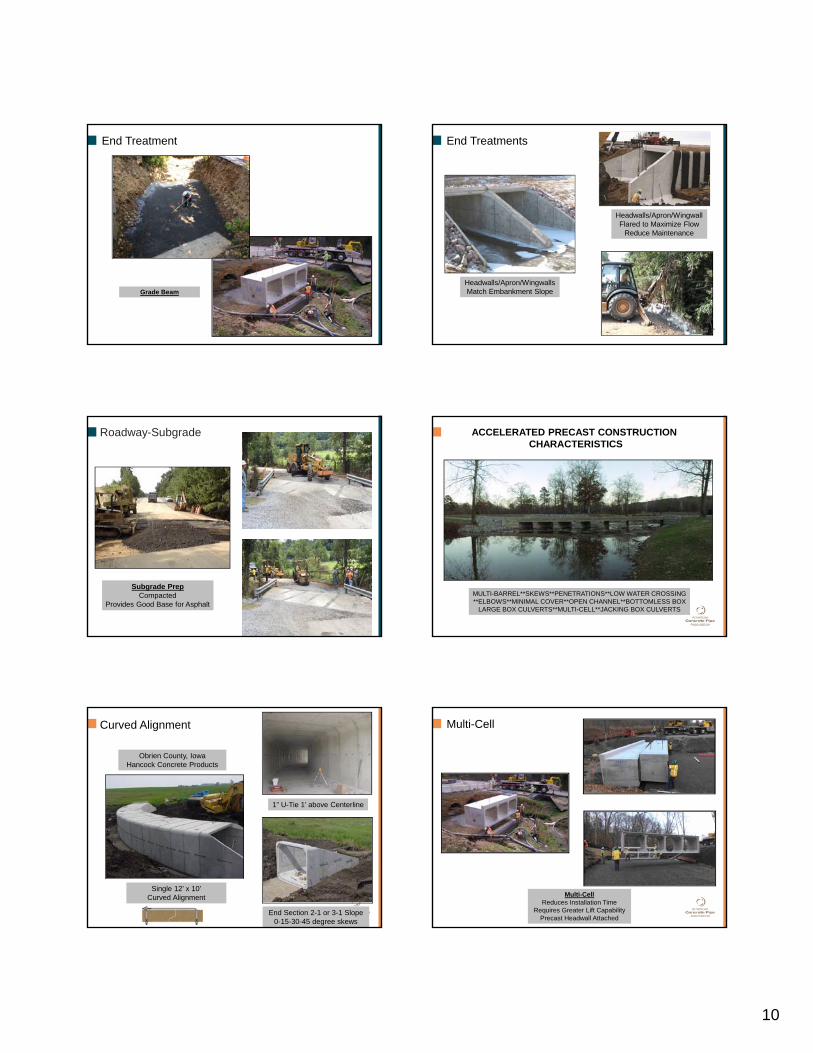
Complete Backfill End Treatments
End TreatmentsFootings
Toe walls/WingwallsAprons
Headwalls#4 Rebar @ 10” o.c. top of headwall#4 J Bar (2 per box) for headwall
End Treatments
Headwalls/Apron/WingwallsWWF exposed along top/walls/bottom
End Treatments
End TreatmentsFootings
Toewalls/WingwallsAprons
10
Grade Beam
End Treatment
Headwalls/Apron/WingwallsMatch Embankment Slope
Headwalls/Apron/WingwallFlared to Maximize Flow
Reduce Maintenance
End Treatments
Roadway-Subgrade
Subgrade PrepCompacted
Provides Good Base for Asphalt
ACCELERATED PRECAST CONSTRUCTION CHARACTERISTICS
MULTI-BARREL**SKEWS**PENETRATIONS**LOW WATER CROSSING**ELBOWS**MINIMAL COVER**OPEN CHANNEL**BOTTOMLESS BOX
LARGE BOX CULVERTS**MULTI-CELL**JACKING BOX CULVERTS
Obrien County, IowaHancock Concrete Products
End Section 2-1 or 3-1 Slope0-15-30-45 degree skews
Single 12’ x 10’Curved Alignment
1” U-Tie 1’ above Centerline
Curved Alignment Multi-Cell
Multi-CellReduces Installation Time
Requires Greater Lift CapabilityPrecast Headwall Attached
11
Mercer CountyLow Flow Culvert
Corbels for Approach Slabs
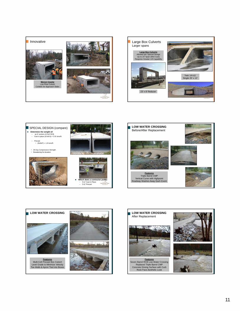
Innovative Large Box CulvertsLarger spans
23’ x 8’ Reducer
Twin 14’x11’Single 20’ x 12’
Large Box CulvertsAllowed per Special DesignUp to 24’ Span (Wet Cast)
Requires Greater Lift Capability
SPECIAL DESIGN (compare) Determine the weight of:
– an 8’ section of 8’x8’ RCB– Cast in place (9.5x9.5) = 2.01 tons/ft.
– Precast (8x8x8”) = 1.8 tons/ft.
28 Day Compressive Strength Dewatering for duration
Which does a contractor prefer:– 5’x2’ Cast In Place– 5’x2’ Precast
FeaturesTriple Barrel CMP
Vertical Curve with HighpointRoadway Washes Away Each Event
LOW WATER CROSSINGBefore/After Replacement
LOW WATER CROSSING
FeaturesMulti-Cell Precast Box Culvert
Level Grade to Minimize VelocityToe-Walls & Apron Tied into Boxes
LOW WATER CROSSINGAfter Replacement
FeaturesSeven Barrel RCB Low Water Crossing
Replaced Triple Barrel CMPConcrete Driving Surface with Curb
Rock Face Aesthetic Look
12
SKEWED END
RCBs are skewed Left Forward Skew
Right Forward SkewLimited: size/degree of skew
SKEWED END/PENETRATION
PENETRATION
FeaturesPenetration Addressed in Plant
Can Design Field Penetration SolutionTop and Bottom Penetrations
Elbows/Bends
FeaturesManufacture Any Bend Angle
Bends on Multi-BarrelsSaves Money/Eliminates Junction Box
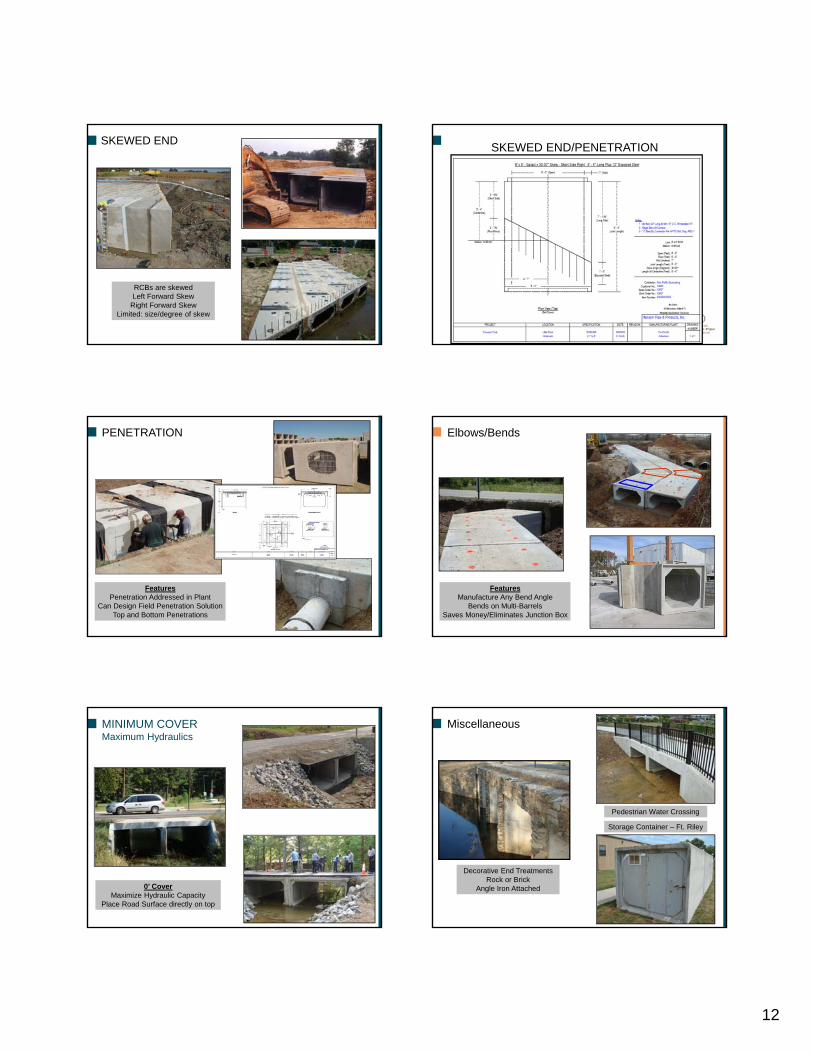
MINIMUM COVERMaximum Hydraulics
0’ CoverMaximize Hydraulic Capacity
Place Road Surface directly on top
Miscellaneous
Decorative End TreatmentsRock or Brick
Angle Iron Attached
Pedestrian Water Crossing
Storage Container – Ft. Riley

13
JackingBox Culverts
Factors1. Nature of soil, water table &
effects of dewatering2. Jacking/Receiving Pit3. Length, alignment and
outside dimension of pipeline4. Jacking Forces5. Pipe Joints6. Loads on shield and pipe7. Size of overbore8. Lubrication9. Grouting10. Spoils Removal
76
ReduceReduce Road User ImpactsReduce CostsReduce Construction TimeReduce Weather Related Time Delays
ImproveImprove Durability/QualityImprove Work Zone Safety
MinimizeMinimize Environmental ImpactMinimize Impact to Existing Roadway Alignment
Accelerated Precast ConstructionFundamentals Attributes
Precast Box CulvertsEase of Construction – Pipe Crew
No Lengthy Design TimeReduced Open Trench Time
77
Thank You
QUESTIONS?