DECENTRALIZED MODULAR ROUTER ARCHITECTURES
175
DECENTRALIZED MODULAR ROUTER ARCHITECTURES Doctoral Thesis Markus Hidell Laboratory for Communication Networks School of Electrical Engineering KTH, Royal Institute of Technology Stockholm 2006
Transcript of DECENTRALIZED MODULAR ROUTER ARCHITECTURES
DECENTRALIZED MODULAR ROUTER ARCHITECTURES
Doctoral Thesis
Markus Hidell
Laboratory for Communication Networks School of Electrical Engineering
KTH, Royal Institute of Technology Stockholm 2006

Decentralized Modular Router Architectures A dissertation submitted to the Royal Institute of Technology (KTH) in partial fulfillment of the requirements for the Doctor of Philosophy degree. Akademisk avhandling som med tillstånd av Kungliga Tekniska Högskolan framlägges till offentlig granskning för avläggande av teknologie doktorsexamen fredagen den 22 september 2006 i Salongen, KTHB, KTH, Stockholm. © Markus Hidell, 2006 Royal Institute of Technology (KTH) School of Electrical Engineering Laboratory for Communication Networks SE-100 44 Stockholm Sweden TRITA-EE 2006:036 ISSN 1653-5146 ISRN KTH/EE—06/036—SE ISBN 91-7178-424-1 Printed by Universitetsservice US-AB, Stockholm 2006

1
ABSTRACT The Internet grows extremely fast in terms of number of users and traffic volume,
as well as in the number of services that must be supported. This development results in new requirements on routers—the main building blocks of the Internet. Existing router designs suffer from architectural limitations that make it difficult to meet future requirements, and the purpose of this thesis is to explore new ways of building routers.
We take the approach to investigate distributed and modular router designs, where routers are composed of multiple modules that can be mapped onto different processing elements. The modules communicate through open well-defined interfaces over an internal network. Our overall hypothesis is that such a combination of modularization and decentralization is a promising way to improve scalability, flexibility, and robustness of Internet routers—properties that will be critical for new generations of routers.
Our research methodology is based on design, implementation, and experimental verification. The design work has two main results: an overall system design and a distributed router control plane. The system design consists of interfaces, protocols, and internal mechanisms for physically separation of different components of a router. The distributed control plane is a decomposition of control software into independent modules mapped onto multiple distributed processing elements. Our design is evaluated and verified through the implementation of a prototype system.
The experimental part of the work deals with two key issues. First, transport mechanisms for communication of internal control information between processing elements are evaluated. In particular, we investigate the use of reliable multicast protocols in this context. Results regarding communication overhead as well as overall performance of routing table dissemination and installation are presented. The results show that even though there are certain costs associated with using reliable multicast, there are large performance gains to be made when the number of processing elements increases. Second, we present performance results of processing routing information in a distributed control plane. These results show that the processing time can be significantly reduced by distributing the workload over multiple processing elements. This indicates that considerable performance improvements can be made through the use of the distributed control plane architecture proposed in this thesis.

2

3
ACKNOWLEDGMENTS First, I would like to thank my main advisor Prof. Gunnar Karlsson for
his guidance, support, and thorough reading of this thesis. Gunnar has provided an inspiring environment and also given me the opportunity to build up an experimental laboratory at LCN. This environment has been a great platform for the thesis work.
The most important person during this work has, without doubt, been my close friend and colleague, Dr. Peter Sjödin. I have had the pleasure to work with Peter during more or less all my professional life so far, and he has also had the role of assistant advisor throughout the thesis work. With his intelligence, generosity, and kindness, Peter has given invaluable support at the professional and the personal level.
I owe a great debt of gratitude also to Dr. Olof Hagsand. Olof is an impressive software architect and researcher, and very professional in all the ways I can think of. The opportunity to work with Olof was one of the main reasons for me to join LCN. I have really enjoyed working together with Olof and I am very happy to have him among my personal friends.
In addition, I would like to thank Tomas Klockar for the chance to collaborate with him during parts of thesis work.
I am also grateful to all other people at LCN that I have learned to know over the years and who have let me take part of their professional experience during seminars and discussions.
My research has been made possible by generous grants from SSF through the Winternet research program, and from the Wallenberg Foundation. I would like to express my gratitude to these organizations.
Last, but not least, I would like to thank my family for their love and understanding. The unlimited support given by my parents goes beyond words. More than ever, I would like to express my love to the most important persons in my life: my lovely wife, Marie, and my wonderful children, Jonna and Jakob.

4
5
TABLE OF CONTENTS
Abstract ........................................................................................................ 1 Acknowledgments........................................................................................ 3 Table of Contents ......................................................................................... 5 1. Introduction........................................................................................ 9
1.1. The IP Router Concept .............................................................11 1.2. IP Router Generations...............................................................12
1.2.1. First Generation of Routers...............................................13 1.2.2. Second Generation of Routers ..........................................14 1.2.3. Third Generation of Routers .............................................15 1.2.4. Further Distribution—the Fourth Router Generation .......16
1.3. Motivations, Problem Statements and Hypotheses...................17 1.3.1. Overall System Design .....................................................20 1.3.2. Internal Network and Transport Mechanisms...................22 1.3.3. Distributed Control ...........................................................23
1.4. Contributions of this Thesis ......................................................24 2. Distributed Modular Router Architectures ...................................... 27
2.1. Related Work ............................................................................28 2.1.1. Modular Routers ...............................................................28 2.1.2. ForCES..............................................................................31 2.1.3. Router and Switch Architectures ......................................36
2.2. Motivations for a Decentralized Modular Design.....................37 2.2.1. Scalability .........................................................................38 2.2.2. Robustness ........................................................................39 2.2.3. Flexibility..........................................................................40 2.2.4. Meeting the Requirements ................................................41
2.3. An Abstract Model of a Decentralized Modular Router...........42 2.4. System Design ..........................................................................44 2.5. The Internal Protocols—Forz ...................................................48
2.5.1. Association........................................................................50 2.5.2. Configuration ....................................................................51 2.5.3. Data Transfer ....................................................................53
2.6. Internal Network .......................................................................54 2.7. Control Element Design and Implementation...........................56
2.7.1. Application-level Interface Representation ......................59 2.7.2. OS-level Interface Representation ....................................61
2.8. Supporting Multiple Control Elements .....................................64 2.8.1. Network Interfaces—Link Objects ...................................65 2.8.2. IP Addresses—Address Objects .......................................65

6
2.8.3. Routing Table Entries—Route Objects.............................65 2.9. Forwarding Element Design and Implementation ....................66
2.9.1. User-space FE Implementation.........................................68 2.9.2. Kernel-based FE Implementation .....................................68 2.9.3. Intel IXP-based FE Implementation .................................69 2.9.4. Xelerated X10-based FE Implementation.........................71
2.10. Conclusions and Further Work .............................................72 3. Transport Mechanisms for Internal Control..................................... 75
3.1. Reliable Multicast .....................................................................76 3.2. Analysis of Reliable Multicast Protocols..................................78
3.2.1. Sender-initiated Protocols.................................................79 3.2.2. Receiver-initiated Protocols..............................................80 3.2.3. Tree-based Protocols.........................................................81 3.2.4. Ring-based Protocols ........................................................82 3.2.5. Asynchronous Layered Coding (ALC) .............................83 3.2.6. Router Assist.....................................................................84 3.2.7. Current Status ...................................................................85 3.2.8. Reliable Multicast for the Internal Network .....................86
3.3. Basic Performance Measurements ............................................87 3.3.1. Experimental Setup...........................................................88 3.3.2. Multiple TCP Connections ...............................................89 3.3.3. Ideal UDP Multicast .........................................................89 3.3.4. Performance Measurements of TCP and UDP .................91 3.3.5. Ideal Case for UDP Multicast ...........................................92
3.4. Performance Evaluation of NORM ..........................................93 3.4.1. NRL NORM .....................................................................95 3.4.2. INRIA NORM ..................................................................95 3.4.3. Transmission Rates ...........................................................95 3.4.4. Aggregation ......................................................................96
3.5. Overall Control Plane Performance ..........................................97 3.5.1. UDP and IP Multicast .......................................................98 3.5.2. Multiple TCP Connections .............................................100 3.5.3. NORM Transmission Rate and Throughput ...................100 3.5.4. Number of Receivers ......................................................102
3.6. Discussion...............................................................................104 3.6.1. Communication Overhead ..............................................104 3.6.2. Overall Performance Using NORM................................105
3.7. Conclusions and Further Work ...............................................106 3.7.1. Communication Overhead ..............................................106 3.7.2. Overall Control Plane Performance ................................106
4. Distributed Control ........................................................................ 109
7
4.1. Related Work ..........................................................................110 4.2. Distributed Control for Redundancy and Load Balancing......115
4.2.1. Decomposition of Control Functions..............................117 4.2.2. Modularization Approach ...............................................120 4.2.3. Decentralization over Processing Elements....................121
4.3. Internal Requirements for Distributed Control .......................124 4.3.1. Initialization of the Distributed Control Function...........125 4.3.2. Service Process Fault Handling ......................................127 4.3.3. Session Manager Fault Handling ....................................129
4.4. Internal Mechanisms for Distributed Control .........................131 4.4.1. Forz API..........................................................................132 4.4.2. Service-specific Inter-process Communication ..............133 4.4.3. Service Configuration .....................................................134 4.4.4. Session Manager Implementation Aspects .....................135
4.5. Decomposing BGP in a Distributed Control Plane.................135 4.5.1. Traditional BGP Implementation....................................135 4.5.2. BGP Modularization and Decentralization .....................137 4.5.3. Initialization and Internal Communication .....................139 4.5.4. Robustness and Performance Aspects.............................140
4.6. Performance Evaluation of a Distributed BGP.......................142 4.6.1. Experimental Setup.........................................................145 4.6.2. Performance Measurements............................................146 4.6.3. Assignment of Routes to Service Processes ...................148 4.6.4. UPDATE Message Size..................................................150 4.6.5. Discussion.......................................................................152
4.7. Conclusion and Further Work.................................................154 5. Conclusions and Further Work ...................................................... 157 References ................................................................................................ 161 Abbreviations ........................................................................................... 169 Appendix: Papers Published in Conjunction with this Work................... 171

8

9
1. INTRODUCTION The Internet can be described as a collection of interconnected networks
to which computers are attached. Computers attached to the Internet can be of a wide range of types and are, according to Internet terminology, commonly referred to as hosts. The devices that are used to transfer data between networks are called routers. The Internet structure according to this terminology is sketched in Figure 1.1.
Hosts and routers communicate over the Internet by using a set of
communications standards known as the TCP/IP Internet Protocol Suite. These standards specify how hosts communicate, how networks are interconnected, as well as how data traffic is forwarded between networks by routers. In short, these communications standards are named TCP/IP after the two main standards—the Transmission Control Protocol (TCP) and the Internet Protocol (IP).
Hosts
NetworkNetwork
Hosts
Hosts
NetworkRouter
Router
Router
Figure 1.1. The Internet and its main components—hosts, routers, and networks.
10
There are several terms that are synonymous with the term router, such as Internet router, IP router, and IP gateway. These terms will be used interchangeably throughout the thesis.
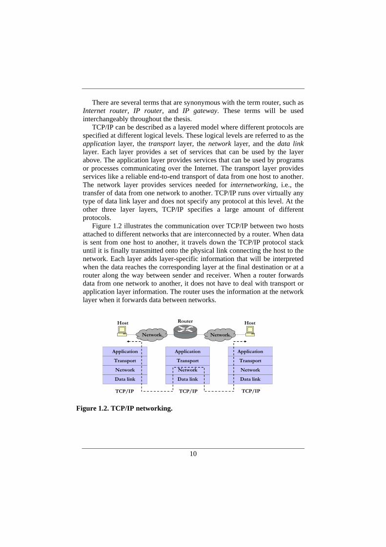
TCP/IP can be described as a layered model where different protocols are specified at different logical levels. These logical levels are referred to as the application layer, the transport layer, the network layer, and the data link layer. Each layer provides a set of services that can be used by the layer above. The application layer provides services that can be used by programs or processes communicating over the Internet. The transport layer provides services like a reliable end-to-end transport of data from one host to another. The network layer provides services needed for internetworking, i.e., the transfer of data from one network to another. TCP/IP runs over virtually any type of data link layer and does not specify any protocol at this level. At the other three layer layers, TCP/IP specifies a large amount of different protocols.
Figure 1.2 illustrates the communication over TCP/IP between two hosts attached to different networks that are interconnected by a router. When data is sent from one host to another, it travels down the TCP/IP protocol stack until it is finally transmitted onto the physical link connecting the host to the network. Each layer adds layer-specific information that will be interpreted when the data reaches the corresponding layer at the final destination or at a router along the way between sender and receiver. When a router forwards data from one network to another, it does not have to deal with transport or application layer information. The router uses the information at the network layer when it forwards data between networks.
Transport
Application
Network
Data link
Host Router Host
Transport
Application
Network
Data link
Transport
Application
Network
Data link
TCP/IP TCP/IP TCP/IP
Network Network
Figure 1.2. TCP/IP networking.
11
This thesis deals with new ways to build IP routers, and we are therefore mainly concerned with the operations performed by routers. Routers operate at the network layer, and the fundamental service at this layer is a data delivery service provided by IP, the Internet Protocol.
IP provides a service where data is divided into units that are sent through the Internet. These units are referred to as IP datagrams or IP packets. IP gives no guarantees that a packet really gets delivered all the way to the receiver. Packets may be lost, duplicated or delayed by the network. Further, IP packets are treated independently from each other, meaning that different packets from a sequence of packets sent by a host may take different paths through the network. Thus, packets may also arrive out of order at the destination. For these reasons, the service provided by IP is commonly called an unreliable, best-effort, connectionless service. If an application program requires a higher degree of service, this has to be provided by higher-level protocols, i.e., at the transport layer or the application layer. It is up to the end-systems to detect and deal with packet delivery problems, not to the routers. Simply put, routers have two main tasks: They decide how packets best be forwarded through the network, and then they move packets between networks according to this strategy.
1.1. The IP Router Concept Routers constitute one of the main building blocks of the Internet in the
sense that they bridge between different network technologies so that a large amount of different networks can be interconnected to form one logical heterogeneous structure—the Internet.
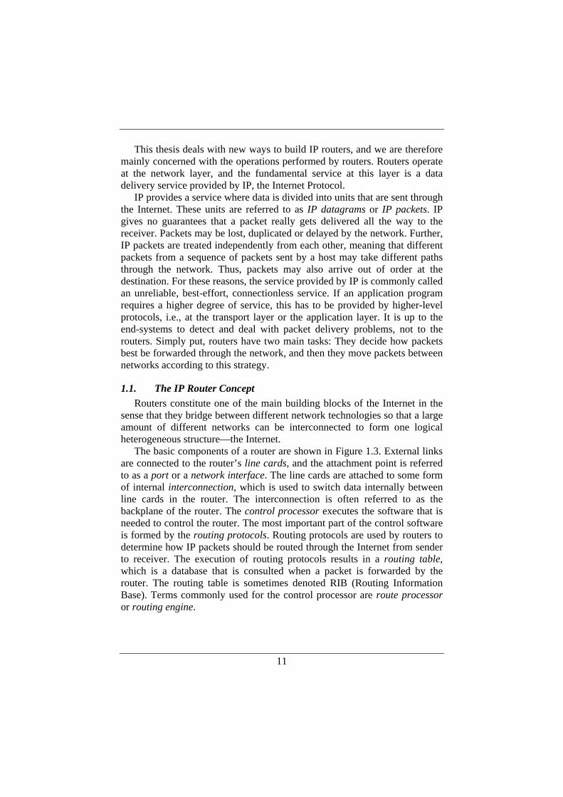
The basic components of a router are shown in Figure 1.3. External links are connected to the router’s line cards, and the attachment point is referred to as a port or a network interface. The line cards are attached to some form of internal interconnection, which is used to switch data internally between line cards in the router. The interconnection is often referred to as the backplane of the router. The control processor executes the software that is needed to control the router. The most important part of the control software is formed by the routing protocols. Routing protocols are used by routers to determine how IP packets should be routed through the Internet from sender to receiver. The execution of routing protocols results in a routing table, which is a database that is consulted when a packet is forwarded by the router. The routing table is sometimes denoted RIB (Routing Information Base). Terms commonly used for the control processor are route processor or routing engine.
12
The traditional way to build routers has been to use a monolithic
architecture, where line cards are connected to a back plane, and a CPU-based controller is used to run routing software, network management software and other types of control software. The line cards and the forwarding functionality are normally referred to as the forwarding plane, while the controller and its functionality are referred to as the control plane.
The forwarding operation can be summarized as follows: A packet enters the router through an incoming port on an ingress line card. Every IP packet carries control information specifying, among other things, its destination address. The destination address is used to perform a lookup in the routing table to find the appropriate outgoing port on the egress line card. Thereafter, the packet is transferred through the interconnection to the egress line card and transmitted onto the outgoing external link.
1.2. IP Router Generations The Internet has been in operation since the 1970s, and IP routers have
gone through several design generations over the decades. The evolution of routers is often described in terms of three generations of architectures [6]. The latest trends, which will be mentioned below but described closely in Chapter 2, could be thought of as the fourth generation of routers.
CPU
Routingtable
Memory
Control processor
Linecard
Linecard
Linecard
Linecard
Interconnection
External linksExternal links
Figure 1.3. Basic components of a router.
13
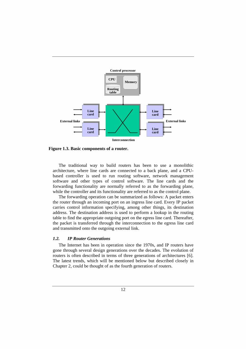
1.2.1. First Generation of Routers The first IP router generation was based on a general purpose processor, a
central processing unit (CPU), where the router’s forwarding functionality was implemented in software executing on the CPU. The architecture can be thought of as a computer where several network interface cards are attached to the computer’s shared bus system. An illustration of this shared-bus architecture is shown in Figure 1.4.
Every packet that passes through the router is processed by the CPU. The
CPU moves the packet from the line card to the buffer memory, where it is temporarily stored while the CPU determines the outgoing line card, through route lookup operations in the RIB. Thereafter, the CPU moves the packet to the outgoing line card for transmission onto the external link. There are several performance limitations with this architecture. First, every packet has to cross the bus twice, and the performance of the bus is shared between all the line cards in a time division fashion. Second, the CPU must process each individual packet passing through the router. Finally, the buffer memory residing on the CPU module is shared between all the line cards making memory bandwidth another limiting factor.
An advantage with the architecture is that the software-based forwarding is flexible, and new forwarding functionality can be added without changes to the hardware. A disadvantage is that packet forwarding can be interrupted when the CPU is occupied with other tasks, such as route computations.
Linecard
Linecard
Linecard
BuffermemoryCPU RIB
Shared bus backplane
Figure 1.4. The architecture for the first generation of routers.
14
Due to its performance limitations, the architecture does not scale to the multigigabit per second line rates available today.
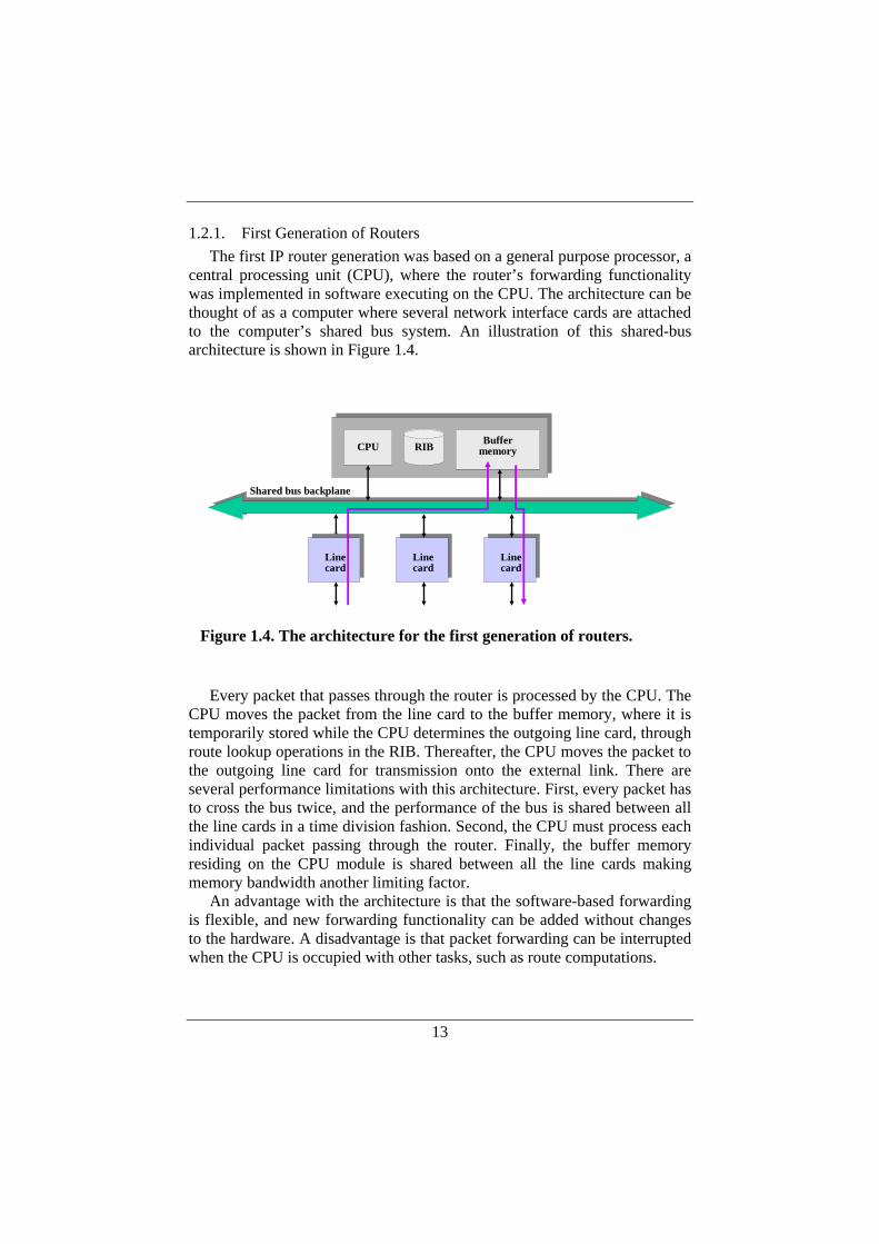
1.2.2. Second Generation of Routers The second router generation addresses several of the performance
limitations described previously. The architecture is still based on a shared bus, but with the difference that line cards are more advanced and can perform packet forwarding without involving the main CPU module, i.e., the control processor. To achieve this, the line cards have been equipped with buffer memory and forwarding functionality in terms of processors or specialized hardware. This can be seen as a first step towards a distributed design approach, and the resulting architecture is depicted in Figure 1.5.
The main improvements compared to the first design generation are that
most of the packets travel over the shared bus only once and that this can be done without the packets being processed by the main CPU. To determine the outgoing port, the line card maintains forwarding information that is condensed from the RIB in the control processor. This information is kept in a local database often called the forwarding information base (FIB), which is updated by the control processor. When a packet enters a line card, the FIB is consulted by the forwarder. If this is enough to determine the outgoing line card, the packet can be forwarded along the fast path, i.e., traveling only once over the shared bus. If not, the packet will be handed over to the control
BuffermemoryCPU RIB
Shared bus backplane
Line cardBuffer
memory
Line cardBuffer
memory
Line cardBuffer
memory
Forwarder Forwarder Forwarder
Figure 1.5. The architecture for the second generation of routers.
15
processor for further processing. This is referred to as the slow path through the router.
Though the second generation was a significant improvement, the shared bus still constitutes a severe bottleneck, and the architecture does not match the continuously increasing line rates.
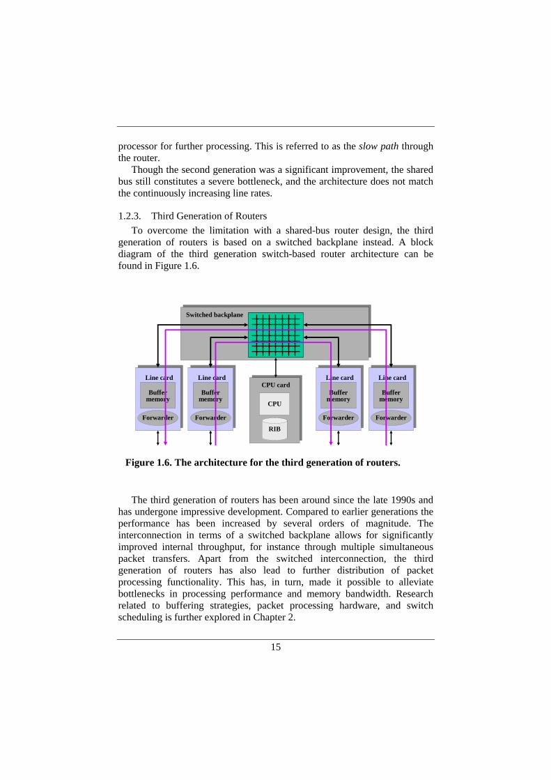
1.2.3. Third Generation of Routers To overcome the limitation with a shared-bus router design, the third
generation of routers is based on a switched backplane instead. A block diagram of the third generation switch-based router architecture can be found in Figure 1.6.
The third generation of routers has been around since the late 1990s and
has undergone impressive development. Compared to earlier generations the performance has been increased by several orders of magnitude. The interconnection in terms of a switched backplane allows for significantly improved internal throughput, for instance through multiple simultaneous packet transfers. Apart from the switched interconnection, the third generation of routers has also lead to further distribution of packet processing functionality. This has, in turn, made it possible to alleviate bottlenecks in processing performance and memory bandwidth. Research related to buffering strategies, packet processing hardware, and switch scheduling is further explored in Chapter 2.
Line card
Buffermemory
Forwarder
Line card
Buffermemory
Forwarder
Line card
Buffermemory
Forwarder
Line card
Buffermemory
Forwarder
CPU
RIB
CPU card
Switched backplane
Figure 1.6. The architecture for the third generation of routers.
16
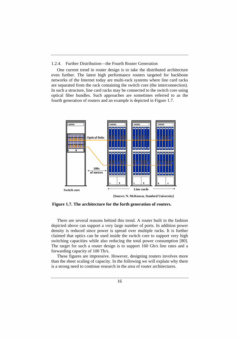
1.2.4. Further Distribution—the Fourth Router Generation One current trend in router design is to take the distributed architecture
even further. The latest high performance routers targeted for backbone networks of the Internet today are multi-rack systems where line card racks are separated from the rack containing the switch core (the interconnection). In such a structure, line card racks may be connected to the switch core using optical fiber bundles. Such approaches are sometimes referred to as the fourth generation of routers and an example is depicted in Figure 1.7.
There are several reasons behind this trend. A router built in the fashion
depicted above can support a very large number of ports. In addition power density is reduced since power is spread over multiple racks. It is further claimed that optics can be used inside the switch core to support very high switching capacities while also reducing the total power consumption [80]. The target for such a router design is to support 160 Gb/s line rates and a forwarding capacity of 100 Tb/s.
These figures are impressive. However, designing routers involves more than the sheer scaling of capacity. In the following we will explain why there is a strong need to continue research in the area of router architectures.
Switch core
Optical links
100sof metres
[Source: N. McKeown, Stanford University]
Line cards
Figure 1.7. The architecture for the forth generation of routers.
17
1.3. Motivations, Problem Statements and Hypotheses The purpose of this thesis is to study architectures for IP routers. The
need for research is motivated by two major challenges in this area: technology trends and service requirements.
The first challenge comes from the developments in optics, where the capacity of WDM-based transmission systems is rapidly increasing. There is no matching development in the electrical domain: processing capacity is increasing slower than optical transmission capacity, and DRAM access speed is increasing even slower. In addition to this, user traffic on the Internet still increases fast (roughly doubling every 12 months). This has implications for the architecture of routers, since the modus operandi of a router is to take a packet from an optical link, process the packet in order to decide how to switch it, and then store the packet in a buffer for later transmission on an outgoing link. The problem then is to find ways to process and buffer packets that can match the capacity of optical links, since an increasing line rate means that the time frame for processing a packet decreases. Furthermore, more ports (network interfaces) are needed which occupies more space. As the number of ports grows and the ports get faster, back planes and internal buses grow faster and wider, occupying more physical space. This leads to an increasing power consumption, which is sometimes considered a serious future problem when deploying high performance routers.
The second challenge comes from requirements for new functionalities in routers. New services appear, which may require modifications of existing protocols, entirely new protocols, or modifications of the ways in which packets are processed in routers. Examples of such services that have been subject to deployment over the latest years are quality of service (QoS), virtual private networks (VPN), and the transition to Internet Protocol version 6 (IPv6). An important problem with the introduction of new services in existing routers is that it requires flexibility in the packet processing path.
In today’s routers, there are normally two data paths available in the forwarding plane—a fast path and a slow path. The fast path is often implemented in ASICs (Application Specific Integrated Circuit), while the slow path typically is based on software executed by a microprocessor. The problem with the fast path is that it is not very flexible, since it is costly to upgrade ASICs. The problem with the slow path is that it is slow, and the introduction of new functionality in routers cannot rely solely on the slow path. It can be concluded that the flexibility requirements are in conflict with the capacity requirements—an increasing amount of packet processing must be performed within a decreasing time frame.
18
The difficulties with an increased complexity in packet processing relates to a router’s data plane, but the continuously growing need for new services and protocols also affects the control plane of routers. The control plane is traditionally a design where a large variety of software functions are integrated into an operating system in a monolithic fashion. This means that adding new services to a router often is a complex task from the control plane point of view. The number of protocols that has to be supported by a router is already significant [7]. These protocols, together with other functions needed in a router, constitute large amounts of complex software. This may consequently result in high demands on the control processing. Thus, it is hard to add new functionality in the control plane and meanwhile maintain a high degree of robustness and efficient execution of the software.
In order to meet the challenges that stem from technology trends and new service requirements, we explore a decentralized modular approach to designing the next generation of routers. It can be noted that router development is already in the process of moving away from traditional centralized router architectures. Packet processing is being pushed to the line cards, where packets can be examined and modified before aggregation of traffic. A result of this development is that high performance routers have grown larger, sometimes consisting of multiple racks operating as one unit. Moreover, the use of optics tends to increase, for performance reasons as well as to save electrical power. Distributed multi-rack systems may be a way to limit the amount of electrical power that must be provided to one unit.
Our intention is to bring decentralization further and study how a router can be modularized for physical separation of control and forwarding functions into multiple modules. Such a modularization requires new mechanisms like well-defined interfaces between modules and new protocols for communication between the modules.
The overall goal of this work is to investigate router architectures that are scalable, both in terms of line speed as well as in number of ports, and at the same time flexible and reliable, and can support different traffic classes. Our view is that new services and improved functionality are kept back by current router architectures. We see decentralization and modularization as means to improve flexibility, scalability, and robustness: flexibility can be achieved by allowing components to be dynamically added, removed and reconfigured; scalability can be achieved by adding more components to the system; robustness can be based on replication of critical components.
This thesis work is divided into two different phases. The first phase is to suggest an overall system design, and the second phase is devoted to design and analysis of specific parts. The system design work mainly concerns the

19
development of protocols and interfaces that are needed in order to modularize a router and physically separate its different components. A result of the first phase is an experimental platform for the analysis of specific parts of the distributed router. The second phase focuses on experiments for evaluating specific parts of the design and this work has been conducted in the experimental networking laboratory at LCN, the Laboratory for Communication Networks at KTH (Royal Institute of Technology). When it comes to the overall system design of a modularized router, the architecture suggested within the IETF ForCES working group [31] will serve as a starting point. The architecture is based on a network element (the NE, i.e., the modularized router), which consists of several control elements (CE) and forwarding elements (FE). Such a modularized router is depicted in Figure 1.8.
Internal Network
NE
Forwarding element
Classifier Forwarder Shaper
Control element
BGP OSPF RSVP
Figure 1.8. A modularized router consisting of control elements and forwarding elements.
20
The CEs implement functions such as routing protocols (e.g., RIP, OSPF, and BGP), signaling protocols (such as the resource reservation protocol RSVP), network management functionality, and configuration tools. Examples of functions implemented in the FEs are forwarding, classification, traffic shaping, and metering. The modules within the NE can be physically separated, and interconnected by some type of high performance LAN technology, such as Gigabit Ethernet.
In the following sections, we discuss problem statements and hypotheses for different parts of the thesis work. Section 1.3.1 deals with issues regarding the overall system design. Thereafter, goals and purposes with studies of the internal network and transport mechanisms are discussed in Section 1.3.2. Finally, Section 1.3.3 is a motivation for the design and analysis of a distributed control plane.
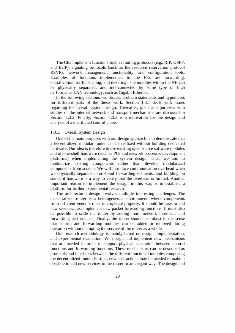
1.3.1. Overall System Design One of the main purposes with our design approach is to demonstrate that
a decentralized modular router can be realized without building dedicated hardware. Our idea is therefore to use existing open source software modules and off-the-shelf hardware (such as PCs and network processor development platforms) when implementing the system design. Thus, we aim to modularize existing components rather than develop modularized components from scratch. We will introduce communication overhead when we physically separate control and forwarding elements, and building on standard hardware is a way to verify that the overhead is limited. Another important reason to implement the design in this way is to establish a platform for further experimental research.
The architectural design involves multiple interesting challenges. The decentralized router is a heterogeneous environment, where components from different vendors must interoperate properly. It should be easy to add new services, i.e., implement new packet forwarding functions. It must also be possible to scale the router by adding more network interfaces and forwarding performance. Finally, the router should be robust in the sense that control and forwarding modules can be added or removed during operation without disrupting the service of the router as a whole.
Our research methodology is mainly based on design, implementation, and experimental evaluation. We design and implement new mechanisms that are needed in order to support physical separation between control functions and forwarding functions. These mechanisms can be described as protocols and interfaces between the different functional modules composing the decentralized router. Further, new abstractions may be needed to make it possible to add new services to the router in an elegant way. The design and
21
implementation is followed by experimental phases where the new mechanisms are evaluated in order to verify our hypothesis.
Within the system design phase of the thesis work, we investigate the following:
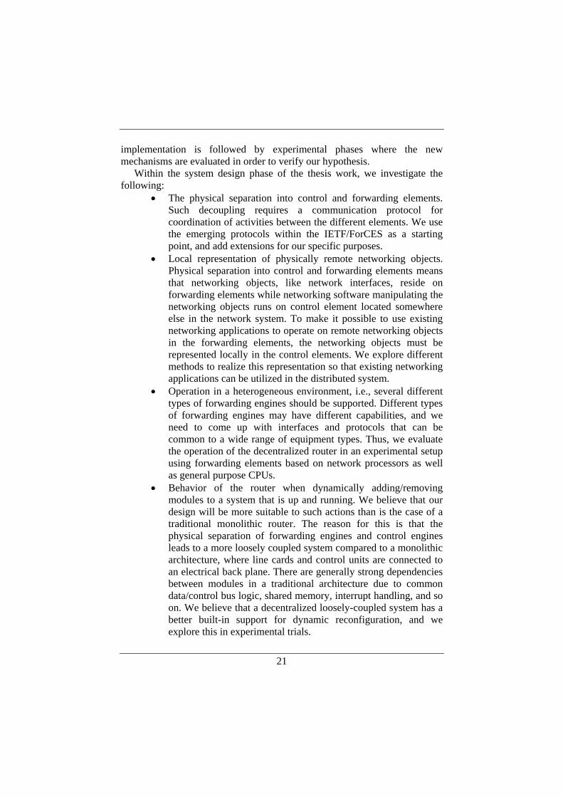
• The physical separation into control and forwarding elements. Such decoupling requires a communication protocol for coordination of activities between the different elements. We use the emerging protocols within the IETF/ForCES as a starting point, and add extensions for our specific purposes.
• Local representation of physically remote networking objects. Physical separation into control and forwarding elements means that networking objects, like network interfaces, reside on forwarding elements while networking software manipulating the networking objects runs on control element located somewhere else in the network system. To make it possible to use existing networking applications to operate on remote networking objects in the forwarding elements, the networking objects must be represented locally in the control elements. We explore different methods to realize this representation so that existing networking applications can be utilized in the distributed system.
• Operation in a heterogeneous environment, i.e., several different types of forwarding engines should be supported. Different types of forwarding engines may have different capabilities, and we need to come up with interfaces and protocols that can be common to a wide range of equipment types. Thus, we evaluate the operation of the decentralized router in an experimental setup using forwarding elements based on network processors as well as general purpose CPUs.
• Behavior of the router when dynamically adding/removing modules to a system that is up and running. We believe that our design will be more suitable to such actions than is the case of a traditional monolithic router. The reason for this is that the physical separation of forwarding engines and control engines leads to a more loosely coupled system compared to a monolithic architecture, where line cards and control units are connected to an electrical back plane. There are generally strong dependencies between modules in a traditional architecture due to common data/control bus logic, shared memory, interrupt handling, and so on. We believe that a decentralized loosely-coupled system has a better built-in support for dynamic reconfiguration, and we explore this in experimental trials.
22
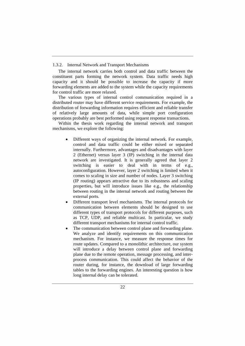
1.3.2. Internal Network and Transport Mechanisms The internal network carries both control and data traffic between the
constituent parts forming the network system. Data traffic needs high capacity and it should be possible to increase the capacity if more forwarding elements are added to the system while the capacity requirements for control traffic are more relaxed.
The various types of internal control communication required in a distributed router may have different service requirements. For example, the distribution of forwarding information requires efficient and reliable transfer of relatively large amounts of data, while simple port configuration operations probably are best performed using request response transactions.
Within the thesis work regarding the internal network and transport mechanisms, we explore the following:
• Different ways of organizing the internal network. For example,
control and data traffic could be either mixed or separated internally. Furthermore, advantages and disadvantages with layer 2 (Ethernet) versus layer 3 (IP) switching in the internal data network are investigated. It is generally agreed that layer 2 switching is easier to deal with in terms of e.g., autoconfiguration. However, layer 2 switching is limited when it comes to scaling in size and number of nodes. Layer 3 switching (IP routing) appears attractive due to its robustness and scaling properties, but will introduce issues like e.g., the relationship between routing in the internal network and routing between the external ports.
• Different transport level mechanisms. The internal protocols for communication between elements should be designed to use different types of transport protocols for different purposes, such as TCP, UDP, and reliable multicast. In particular, we study different transport mechanisms for internal control traffic.
• The communication between control plane and forwarding plane. We analyze and identify requirements on this communication mechanism. For instance, we measure the response times for route updates. Compared to a monolithic architecture, our system will introduce a delay between control plane and forwarding plane due to the remote operation, message processing, and inter-process communication. This could affect the behavior of the router during, for instance, the download of large forwarding tables to the forwarding engines. An interesting question is how long internal delay can be tolerated.
23
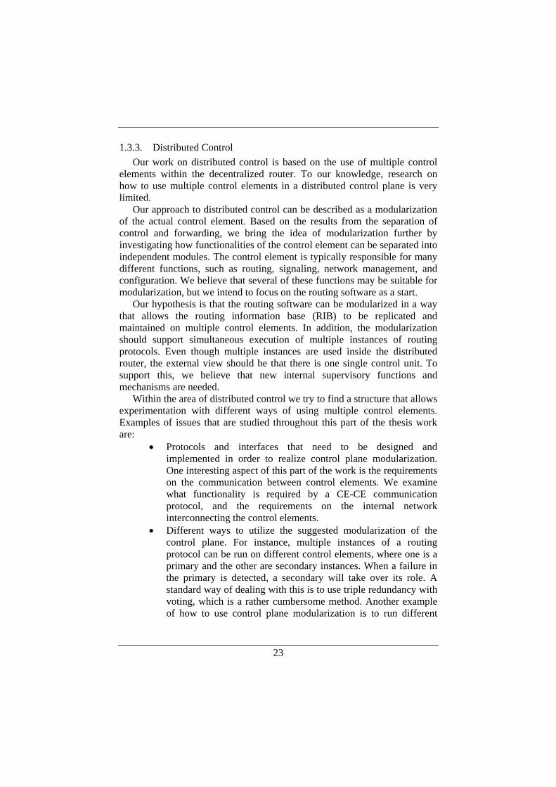
1.3.3. Distributed Control Our work on distributed control is based on the use of multiple control
elements within the decentralized router. To our knowledge, research on how to use multiple control elements in a distributed control plane is very limited.
Our approach to distributed control can be described as a modularization of the actual control element. Based on the results from the separation of control and forwarding, we bring the idea of modularization further by investigating how functionalities of the control element can be separated into independent modules. The control element is typically responsible for many different functions, such as routing, signaling, network management, and configuration. We believe that several of these functions may be suitable for modularization, but we intend to focus on the routing software as a start.
Our hypothesis is that the routing software can be modularized in a way that allows the routing information base (RIB) to be replicated and maintained on multiple control elements. In addition, the modularization should support simultaneous execution of multiple instances of routing protocols. Even though multiple instances are used inside the distributed router, the external view should be that there is one single control unit. To support this, we believe that new internal supervisory functions and mechanisms are needed.
Within the area of distributed control we try to find a structure that allows experimentation with different ways of using multiple control elements. Examples of issues that are studied throughout this part of the thesis work are:
• Protocols and interfaces that need to be designed and implemented in order to realize control plane modularization. One interesting aspect of this part of the work is the requirements on the communication between control elements. We examine what functionality is required by a CE-CE communication protocol, and the requirements on the internal network interconnecting the control elements.
• Different ways to utilize the suggested modularization of the control plane. For instance, multiple instances of a routing protocol can be run on different control elements, where one is a primary and the other are secondary instances. When a failure in the primary is detected, a secondary will take over its role. A standard way of dealing with this is to use triple redundancy with voting, which is a rather cumbersome method. Another example of how to use control plane modularization is to run different
24
routing protocols on different control elements to distribute workload or to limit damages if a control element goes down.
• Different arrangements in order to be able to suggest how control functions of the router can be suitably distributed over multiple control elements from different perspectives, such as from a redundancy, workload, or manageability perspective.
1.4. Contributions of this Thesis The major contributions of this thesis are:
• The system design and implementation of a decentralized modular router based on physically separated control and forwarding elements.
• Realization of a well-defined communication interface between functional elements composing a distributed router.
• Extensive experimental studies of internal transport mechanisms for communication between control and forwarding elements.
• The proposal of a distributed and modular router control plane architecture for improved control plane robustness and performance.
• Experimental verification regarding the control plane performance in terms of route updates processing when the computational workload is distributed over multiple processing elements.
The system design and implementation work presented in this thesis has been performed in collaboration with Dr. Olof Hagsand and Dr. Peter Sjödin, who has been my second advisor throughout the thesis work.
Olof Hagsand took the first initiative to the implementation work by starting the development of the configuration part of the Forz protocol based on an application-level reference model of a forwarding element. Olof Hagsand also coarsely outlined the software architecture. The work was continued by the author of this thesis, who further developed the Forz protocol, the reference model of the forwarding element, other types of forwarding elements, as well as the major part of the control element software. Peter Sjödin contributed to the design work in general and to the implementation work in terms of further development of the Forz data transfer part. We have also had two master thesis projects working on the forwarding elements based on network processors that are briefly described in the thesis.
25
All experimental work regarding investigations of internal transport mechanisms presented in this thesis has been performed by the author. This includes the development of measurement methods, integration and adaptation of third-party software in terms implementations of reliable multicast protocols, the development of experimental setups, and the actual performance measurements.
The author of the thesis is the main architect behind the proposed distributed control plane design, and the suggestions for how control functions can be distributed over multiple control elements. The experimental work in this area was performed by the author. The experimental setup was designed in collaboration with Tomas Klockar, who implemented the first version of a session manager for the experimental work. Tomas also developed the control traffic generator based on live route update traces from the Internet.

26
27
2. DISTRIBUTED MODULAR ROUTER ARCHITECTURES
The rapid growth of the Internet in terms of traffic volumes and number of users, combined with an increasing demand for new services, pose new requirements on routers and other network systems when it comes to scalability, flexibility, and robustness.
To meet these requirements, we take the approach to investigate distributed and modular designs, where the network system is composed of multiple modules (or elements), which communicate through open well-defined interfaces over an internal network. This allows for a network system where modules can be developed and manufactured by different vendors.
We believe that such a design has several advantages. Scalability is improved because modules can be added as capacity requirements increase. Flexibility comes from the ability to dynamically add, remove and modify modules. Robustness is mainly due to two factors: First, the modularity makes it possible to use redundancy and replication of critical functionality over multiple modules. Second, the modular structure in itself tends to limit the impact of faults in individual modules, and encourages sound engineering design principles.
In this chapter we discuss issues associated with distributed router design, and report our experiences from designing and implementing a distributed router prototype. We consider a distributed router that consists of control elements (CEs) and forwarding elements (FEs), which are physically separated and interconnected by a general purpose network. CEs implement functions such as routing protocols, signaling protocols, and network management, while FEs perform for example packet forwarding, classification, traffic shaping, and metering. Together the CEs and FEs form a network element (NE)—a distributed router. This terminology comes from the ForCES [31] working group within the IETF.
The approach we have taken for our prototype is that it should be based on existing, open source software for control, and use different types of hardware platforms for packet forwarding. One goal is to be able to use networking tools available on current PC-based UNIX platforms for our CEs, in combination with special packet forwarding hardware for FEs. We focus on two aspects of designing and implementing such a system. The first aspect is the design of the protocols for communication between CEs and FEs; this involves for example dynamic configuration and discovery, and distribution of system management events. The second aspect is the control
28
software in the CEs: our approach to use existing networking applications requires an additional, intermediate system level in the CEs. This level distributes control information between the local CE, other CEs and remote FEs. In addition, this level also makes remote devices on FEs to appear as local devices in the CE, so that networking applications may be unaware that they are dealing with remote units.
The rest of this chapter is organized as follows. Section 2.1 describes related work. In Section 2.2, we discuss the motivations for a modular and decentralized design approach for the next generation of routers. An abstract model of a distributed router is provided in Section 2.3, and general system design issues are dealt with in Section 2.4. Section 2.5 covers the design of internal communication protocols, which is followed by a discussion around the internal network in Section 2.6. Design and implementation of the elements composing the distributed router are presented in Section 2.7-2.9 Section 2.10 concludes the chapter and outlines further work.
2.1. Related Work Previous research on router architectures spans over several research
areas, such as classification/lookups, internal switch architectures, software modularization and packet forwarding extensions, queuing strategies and scheduling, resource management and QoS. Many of these areas are of interest to our research on distributed router architectures, and a broad understanding of these areas is useful for the overall system design included in our work.
We have chosen to make a closer description of the state of the art in the areas that are most related to the topic of decentralized modular router architectures and to try to explain how previous work in these areas are related to our work.
2.1.1. Modular Routers Our work in the area of modular routers stems from research previously
done in the areas of active networks and extensible routers, where a considerable effort has been spent on router modularization. The main goal there is to support extensibility, i.e. the ability to dynamically reconfigure a router to support new services and applications [12], [23], [24], [44], [45], [49], [52], [58], [66]. The focus is on support for software extensibility, to allow the packet processing software to be dynamically modified. The physical configurations are often monolithic, and to our knowledge little work has been done in the area of hardware extensibility and decentralization.
29
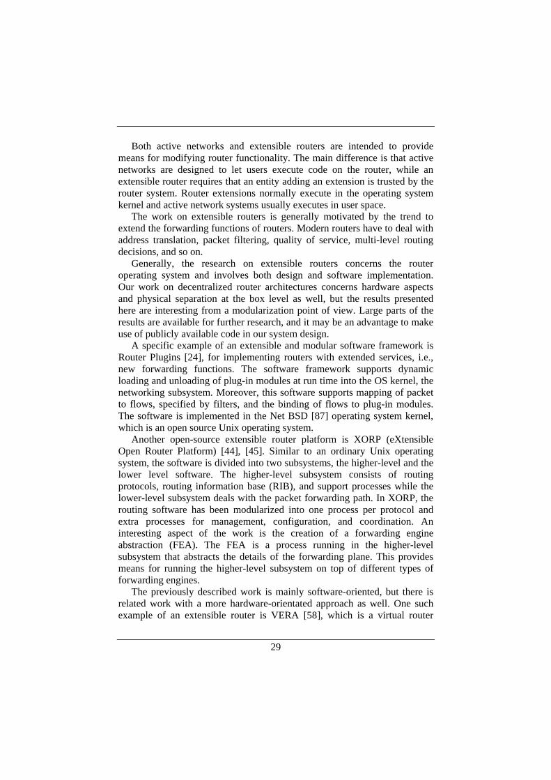
Both active networks and extensible routers are intended to provide means for modifying router functionality. The main difference is that active networks are designed to let users execute code on the router, while an extensible router requires that an entity adding an extension is trusted by the router system. Router extensions normally execute in the operating system kernel and active network systems usually executes in user space.
The work on extensible routers is generally motivated by the trend to extend the forwarding functions of routers. Modern routers have to deal with address translation, packet filtering, quality of service, multi-level routing decisions, and so on.
Generally, the research on extensible routers concerns the router operating system and involves both design and software implementation. Our work on decentralized router architectures concerns hardware aspects and physical separation at the box level as well, but the results presented here are interesting from a modularization point of view. Large parts of the results are available for further research, and it may be an advantage to make use of publicly available code in our system design.
A specific example of an extensible and modular software framework is Router Plugins [24], for implementing routers with extended services, i.e., new forwarding functions. The software framework supports dynamic loading and unloading of plug-in modules at run time into the OS kernel, the networking subsystem. Moreover, this software supports mapping of packet to flows, specified by filters, and the binding of flows to plug-in modules. The software is implemented in the Net BSD [87] operating system kernel, which is an open source Unix operating system.
Another open-source extensible router platform is XORP (eXtensible Open Router Platform) [44], [45]. Similar to an ordinary Unix operating system, the software is divided into two subsystems, the higher-level and the lower level software. The higher-level subsystem consists of routing protocols, routing information base (RIB), and support processes while the lower-level subsystem deals with the packet forwarding path. In XORP, the routing software has been modularized into one process per protocol and extra processes for management, configuration, and coordination. An interesting aspect of the work is the creation of a forwarding engine abstraction (FEA). The FEA is a process running in the higher-level subsystem that abstracts the details of the forwarding plane. This provides means for running the higher-level subsystem on top of different types of forwarding engines.
The previously described work is mainly software-oriented, but there is related work with a more hardware-orientated approach as well. One such example of an extensible router is VERA [58], which is a virtual router
30
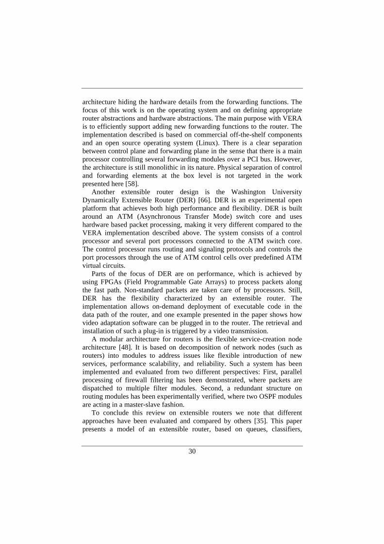
architecture hiding the hardware details from the forwarding functions. The focus of this work is on the operating system and on defining appropriate router abstractions and hardware abstractions. The main purpose with VERA is to efficiently support adding new forwarding functions to the router. The implementation described is based on commercial off-the-shelf components and an open source operating system (Linux). There is a clear separation between control plane and forwarding plane in the sense that there is a main processor controlling several forwarding modules over a PCI bus. However, the architecture is still monolithic in its nature. Physical separation of control and forwarding elements at the box level is not targeted in the work presented here [58].
Another extensible router design is the Washington University Dynamically Extensible Router (DER) [66]. DER is an experimental open platform that achieves both high performance and flexibility. DER is built around an ATM (Asynchronous Transfer Mode) switch core and uses hardware based packet processing, making it very different compared to the VERA implementation described above. The system consists of a control processor and several port processors connected to the ATM switch core. The control processor runs routing and signaling protocols and controls the port processors through the use of ATM control cells over predefined ATM virtual circuits.
Parts of the focus of DER are on performance, which is achieved by using FPGAs (Field Programmable Gate Arrays) to process packets along the fast path. Non-standard packets are taken care of by processors. Still, DER has the flexibility characterized by an extensible router. The implementation allows on-demand deployment of executable code in the data path of the router, and one example presented in the paper shows how video adaptation software can be plugged in to the router. The retrieval and installation of such a plug-in is triggered by a video transmission.
A modular architecture for routers is the flexible service-creation node architecture [48]. It is based on decomposition of network nodes (such as routers) into modules to address issues like flexible introduction of new services, performance scalability, and reliability. Such a system has been implemented and evaluated from two different perspectives: First, parallel processing of firewall filtering has been demonstrated, where packets are dispatched to multiple filter modules. Second, a redundant structure on routing modules has been experimentally verified, where two OSPF modules are acting in a master-slave fashion.
To conclude this review on extensible routers we note that different approaches have been evaluated and compared by others [35]. This paper presents a model of an extensible router, based on queues, classifiers,
31
forwarders, and schedulers. The model is used when comparing the different designs and it may prove useful for our system design work.
2.1.2. ForCES In the area of decentralized architectures, our work builds on efforts in
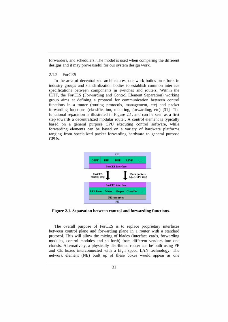
industry groups and standardization bodies to establish common interface specifications between components in switches and routers. Within the IETF, the ForCES (Forwarding and Control Element Separation) working group aims at defining a protocol for communication between control functions in a router (routing protocols, management, etc) and packet forwarding functions (classification, metering, forwarding, etc) [31]. The functional separation is illustrated in Figure 2.1, and can be seen as a first step towards a decentralized modular router. A control element is typically based on a general purpose CPU executing control software, while forwarding elements can be based on a variety of hardware platforms ranging from specialized packet forwarding hardware to general purpose CPUs.
The overall purpose of ForCES is to replace proprietary interfaces
between control plane and forwarding plane in a router with a standard protocol. This will allow the mixing of blades (interface cards, forwarding modules, control modules and so forth) from different vendors into one chassis. Alternatively, a physically distributed router can be built using FE and CE boxes interconnected with a high speed LAN technology. The network element (NE) built up of these boxes would appear as one
OSPF RIP BGP RSVP ....
ForCES interface
CE
LPF Forw Meter Shaper Classifier ....
ForCES interface
FEFE resources
ForCEScontrol msg
Data packetse.g., OSPF msg
Figure 2.1. Separation between control and forwarding functions.
32
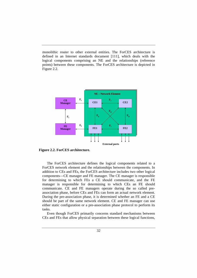
monolithic router to other external entities. The ForCES architecture is defined in an Internet standards document [111], which deals with the logical components comprising an NE and the relationships (reference points) between these components. The ForCES architecture is depicted in Figure 2.2.
The ForCES architecture defines the logical components related to a
ForCES network element and the relationships between the components. In addition to CEs and FEs, the ForCES architecture includes two other logical components—CE manager and FE manager. The CE manager is responsible for determining to which FEs a CE should communicate, and the FE manager is responsible for determining to which CEs an FE should communicate. CE and FE managers operate during the so called pre-association phase, before CEs and FEs can form an actual network element. During the pre-association phase, it is determined whether an FE and a CE should be part of the same network element. CE and FE manager can use either static configuration or a pre-association phase protocol to perform its tasks.
Even though ForCES primarily concerns standard mechanisms between CEs and FEs that allow physical separation between these logical functions,
CE1 CE2
FE1 FE2
CEManager
FEManager
Fp
Fr
Fi
Fl
Ff
Fc
Fp
Fp
NE – Network Element
External ports Figure 2.2. ForCES architecture.

33
the ForCES architecture also defines other interfaces between the logical components of an FE. These interfaces are the following (see Figure 2.2):
• Fp: CE-FE interface over which the ForCES protocol is defined • Fi: FE-FE interface, which is the data path between FEs • Fr: CE-CE interface, for information exchange between CEs • Fc: interface between CE manager and CE (pre-association) • Ff: interface between FE manager and FE (pre-association) • Fl: interface between CE manager FE manager (optional)
The ForCES protocol executes over the Fp reference point and includes two parts: association establishment and steady-state communication. The period of time when the ForCES protocol is executed is referred to as the post-association phase. CEs and FEs communicate in a master-slave fashion, where CEs are masters and FEs are slaves.
The purpose of the association establishment phase is to establish communication between FEs and CEs within the same NE. The phase is initiated by FEs, requesting to join the NE. If the request is granted by a CE, the phase will typically continue with the FE being queried of its capabilities and given an initial configuration by the CE. When the FE is ready to start the forwarding of packets, the association phase is completed. The procedure is illustrated in Figure 2.3.
FE CESecurity exchange
Join request
Join response
Capability query
My functions
Initial configuration
Ready to go, shall I?
Go ahead!
Figure 2.3. ForCES association establishment.
34
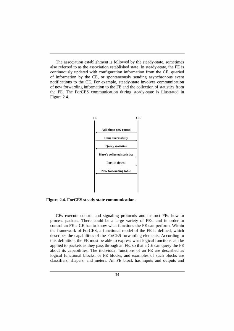
The association establishment is followed by the steady-state, sometimes also referred to as the association established state. In steady-state, the FE is continuously updated with configuration information from the CE, queried of information by the CE, or spontaneously sending asynchronous event notifications to the CE. For example, steady-state involves communication of new forwarding information to the FE and the collection of statistics from the FE. The ForCES communication during steady-state is illustrated in Figure 2.4.
CEs execute control and signaling protocols and instruct FEs how to
process packets. There could be a large variety of FEs, and in order to control an FE a CE has to know what functions the FE can perform. Within the framework of ForCES, a functional model of the FE is defined, which describes the capabilities of the ForCES forwarding elements. According to this definition, the FE must be able to express what logical functions can be applied to packets as they pass through an FE, so that a CE can query the FE about its capabilities. The individual functions of an FE are described as logical functional blocks, or FE blocks, and examples of such blocks are classifiers, shapers, and meters. An FE block has inputs and outputs and
FE CE
Add these new routes
Done successfully
Query statistics
Here’s collected statistics
Port 14 down!
New forwarding table
Figure 2.4. ForCES steady state communication.
35
several FE blocks are connected together to form a data path along which a packet travels. By controlling the individual FE blocks, a CE can decide how an FE should process packets.
The ForCES architecture permits the use of multiple CEs for purposes like redundancy and load sharing. The use of multiple CEs is considered to be implementation specific and, accordingly, ForCES does not specify any protocols between CEs, i.e., over the Fr reference point. However, ForCES claims that the support for dynamic changes to the CE/FE association should be able to support CE graceful restart in a straight-forward fashion. Graceful restart is a high availability mechanism that has been proposed for routing protocols [84], [100] as well as for MPLS (Multiprotocol Label Switching) [67], [97] to mitigate the effects of a restarting router. The overall idea with graceful restart is to avoid unnecessary re-computation of the routing table when a neighboring router is restarting. If the restarting router can inform its neighbors of a restart, they can assume that the routes they have received from the restarting router before restart are still valid for a certain amount of time. In the context of ForCES this means that an FE can continue to forward packets according to its forwarding table when its CE performs a graceful restart. To support this kind of non-stop forwarding, which is a requirement for graceful restart, the FEs should cache and hold on to its forwarding state when its CE restarts. In addition, a CE should be able to inform its FEs what to do if their CE fails during the ForCES association establishment phase. The use of multiple CEs is an important part of this thesis and is further discussed in Section 2.8 as well as in Chapter 4.
To our knowledge, experimental research on ForCES has so far been limited, partly due to the fact that the ForCES protocol specification is not yet finalized and it is hard to find implementations that can be used for experimental work. A prototype implementation of an early proposal for the ForCES protocol, called Netlink2, has been evaluated [36], and this work covers a throughput analysis of communication between one control element and two forwarding elements.
Recently, work has been done regarding the combination of programmable networks with the ForCES architecture. This work has been performed within the FlexiNET project [71]. One objective of the project is to achieve a dynamic deployment of new services in a distributed router environment. Similar to our design (presented later in this chapter), the distributed router is built using off-the-shelf boxes interconnected in a LAN. To the outside world, the distributed router appears as one single router. Within this work, a ForCES gateway, referred to as ForCEG, has been introduced between the control plane and the forwarding plane [41]. The ForCEG implements the CE side of the ForCES protocol and it also
36
performs translation between configuration commands originating from the control plane and ForCES configuration messages sent to the FEs. The main purpose is to deal with the complexity caused by an increasing number of service APIs in control plane software. ForCEG is also claimed to serve another important purpose: In the case of using multiple CEs, there may be conflicts due to e.g., inconsistent configuration of forwarding information. This may for example occur if two different CEs compute two different best routes to a particular destination. ForCEG is responsible for resolving such conflicts.
Finally, research on how to build a ForCES-based experimental network to improve security, reliability, and scalability has recently been published [46].
2.1.3. Router and Switch Architectures The term distributed router is sometimes used for single-chassis routers
where the packet forwarding and lookup operations are performed on the line cards—a more limited degree of distributed functionality [16]. We use the term in the more general sense to denote a system with several independent elements, which are physically separated and interconnected by a network.
Research on router and switch architectures often relates to the actual interconnect for line cards, which is an area where a significant amount of work has been performed over the years [17], [18], [54], [60], [61], [78], [79], [93]. The objective is normally the sheer scaling of switching capacity, sometimes in combination with supporting an increasing number of ports. From an overview perspective, this type of work often deals with memory bandwidth limitations, buffer placement strategies, and switch matrix scheduling algorithms.
One approach that gained attention during the late 1990s was to use crossbars together with input queuing to achieve high performance and 100% throughput [78], [79]. A crossbar is a switched interconnection between input and output ports, where a controller is used to activate paths between inputs and outputs. One main challenge when using crossbars is the switch matrix scheduler, which decides how to configure the crossbar at any given time. This scheduler is centralized, and several such schedulers have been suggested over the years. One example is the iSLIP scheduler [78], which is claimed to be practical to implement and capable of performing 100 million arbitration decisions per second, using contemporary hardware.
The use of crossbars, input queuing, and a centralized scheduler was successfully adopted in commercial Internet core routers [20]. Still, such a centralized approach has limited scaling properties and has therefore been
37
designed for a fairly low number of ports. As a consequence, new solutions must be sought when line rates and number of ports increase.
One current trend is that router and switch architectures are becoming more distributed, where decentralized solutions are explored in order to eliminate centralized scheduling. Such research efforts to improve the scaling of Internet routers can be recognized both within the research community and within industry [20], [55], [60]. Recent commercial high-performance routers are based on distributed multi-chassis solutions, where line card chassis are connected to a switch fabric chassis.
One interesting example of research on distributed router architectures is the Stanford 100 Tb/s router [60], [61]. The design is based on a load-balanced switch architecture originally described by C-S. Chang et al [17], [18]. The load-balanced switch forms a recent interesting alternative to crossbars with centralized schedulers due to its scaling properties. The load-balanced switch is based on 3 stages of line cards where optical switching can be used between the stages.
The way the load-balanced switch is used in the Stanford 100 Tb/s router architecture, is that the two stages of optical switching are identical. The first switching stage spreads the traffic uniformly over the line cards in the center stage. The center stage is buffered where one FIFO queue per output is used. This arrangement of FIFOs is commonly known as VOQs—Virtual Output Queues. The second stage of the optical switch serves these VOQs at a fixed rate.
One of the main virtues with the load-balanced switch is that there is no need for centralized scheduling. Instead, the switches walk through a cyclic sequence of configurations. Another advantage is that input buffering can be used, meaning that there is no need for memories operating faster than line rate. Finally, the use of optics allows high switching capacity without unrealistic requirements on power consumption. For these reasons, it is claimed that the router design based on this load-balanced switch architecture has excellent scaling properties in terms of capacity and number of ports.
A prototype implementation of the 100 Tb/s router is under development, where line card chassis are connected to the optical switch fabric using fiber bundles spanning over 100s of meters. This is truly a distributed approach to building routers. However, from a logical viewpoint it is still a closed system without open, well-defined interfaces for internal communication.
2.2. Motivations for a Decentralized Modular Design As mentioned earlier, one current trend in the development of routers is a
decentralized design where control and forwarding functions are physically
38
separated. This can be described as a way of decoupling of packet forwarding capability from control functionality.
The router architecture proposed in this thesis takes this decentralization and modularization further and can be described as a network of different processing elements (or nodes), running a modularized set of functions with a well-defined interface. For instance, some nodes may be responsible for control functions like routing protocols, signaling protocols, or network management. Others may be responsible for packet forwarding functions, differentiated services classification, or firewall functions. The different processing elements are interconnected using high performance switches (e.g., Gigabit Ethernet or 10-Gigabit Ethernet). Such a router design can be seen as a hybrid between a network and a router, but would still be regarded as one single router from an external viewpoint.
We believe that the most important properties of the next generation router architectures will be scalability, robustness, and flexibility. In the following sections, we discuss the meaning of these properties and what requirements they pose on the router design. We also argue that a decentralized and modular router would prove beneficial in these aspects.
2.2.1. Scalability Scalability is a multi-facetted issue. Examples of scaling properties are:
• Number of ports (network interfaces) supported by the router. • Data forwarding capacity of the router. • Size of the state, e.g., various tables that the control and
forwarding planes can hold. • Amount of signaling that can be handled by the router. • Power consumption.
A router should scale both in terms of number of ports that can be connected to the router and in terms of data forwarding capacity. Forwarding capacity means both the number of bits per second and, even more important, the number of packets per second that the router can forward. It is also important that a router can be dynamically extended in these respects. In addition, it is required that this can be done without disrupting the router’s normal operation, so called in-service upgrades.
The state of control and forwarding planes refers to various tables that must be maintained in the router. Examples of such tables are routing tables, forwarding tables, access control lists (ACLs), and so on. These tables tend to grow both in size and number of tables over time. The router may have to cope with large tables and perform various lookups in these tables without sacrificing packet forwarding performance.

39
Another issue related to scaling of the control plane is the amount of signaling that can be handled. One example is the number of BGP route updates per second that can be processed by the control plane. A router with several BGP peers will have to handle large amounts of messages that must be authenticated, which in turn consumes significant amounts CPU resources.
Finally, power consumption is becoming a scaling issue. The latest commercial high performance core routers consume power in the order of what can be provided in a point of presence (POP) today. It is a challenge to continue to increase capacity and number of ports and still maintain reasonable level of power consumption.
2.2.2. Robustness Reliability in routers is becoming more and more important as the
commercial use of the Internet grows, and the general meaning of the term is that the services provided by the router should be available 99.999% of the time. In addition, the services should be provided in an accurate way without erroneous handling of traffic. Robustness is important both in the control plane and in the forwarding plane of the router. Some examples of robustness properties are:
• Redundant functionality. • Maintaining forwarding functionality if control plane temporarily
goes down. • Multiple communication paths in the router’s interconnection.
Robustness can be achieved in several different ways, e.g., through replication, load sharing, and functional separation (distributed control).
One dimension of robustness is to provide redundancy through the sheer replication of functionality. The purpose of replicating functionality is obvious; reliable routers should not have single points of failure. The challenge is to coordinate the redundant functions.
An intuitive way of coordinating multiple redundant functions is to run them in a master-slave fashion. The slaves are passive copies of the active master and a slave can be invoked when the master stops working properly.
An alternative way is to do load sharing. This means that several copies of a computing element are active simultaneously and computational tasks are spread out over these nodes. If one of them fails, the others will continue to run, and the function will thus still be executed, but with reduced performance. Robustness through replication is important for control functionality as well as for forwarding functionality and for the interconnection between the line cards in a router.

40
Another dimension of robustness is to decouple forwarding functionality from control functionality so that forwarding functions can continue to operate even if the control plane temporarily goes down. This means that the router can serve traffic according to the latest state of forwarding tables before the control plane stopped. State changes cannot be dealt with until the control plane is up and running again.
We believe that passive redundancy, load sharing, and separation between control and forwarding can be efficiently used in a distributed environment, like a decentralized router. For instance, robustness in the control plane can be provided through the use of decentralizing separate different functions of the router over different processing elements. This can be referred to as distributed control. The purpose is to eliminate dependencies between functions so that potential errors can be isolated. An example can be taken from the routing software. Often, all routing protocols supported by a router are executed by one single processor, sometimes even as one single large process. Then, if an error in a specific routing function causes a crash, all routing protocols may stop working. Instead, the software can be modularized and the different protocols be distributed over different processing elements. Thus, if one processing element goes down the damage will be isolated to a specific routing protocol, and the remaining protocols can continue to operate.
2.2.3. Flexibility Flexibility relates to the introduction of new services in the router and has
several dimensions: • Ability to modify the packet processing along the data paths in
the router. • Ability to modify and extend to the control plane of the router. • Ability to mix network interfaces of various types to a reasonable
cost. In the context of packet forwarding, flexibility primarily means the ability
to modify the per-packet processing functions in the router. Many new services affect the way packets are processed inside the router. This is a challenge due to the fact that increasing external line rate limits the amount of time a packet can spend being processed inside the router. The current trend is that external line rate increases faster than logic and memory speed, meaning that the allowed packet processing time decreases while the amount of work that has to be done for each packet increases.
In addition to flexibility in the data plane, there is a need to be able to modify the control plane. Introducing a new service normally means that both the control plane and the forwarding plane need to be updated. New
41
services are constantly being developed, which makes the software-intense control plane grow in size and complexity. Flexibility is an important issue also for the control plane in the sense that it must be possible to add new services while still maintaining a robust control plane implementation and thus maintaining a high availability.
Yet another dimension of flexibility relates to the mix of network interfaces that can be supported by the router. Technically, this may not be an issue since virtually any router can support many types of interfaces. However, in the case of high performance routers the interface cards are normally attached to a high-speed back-plane. This means that low-speed network interfaces become unnecessarily expensive. We refer to flexibility in this sense as the possibility to support low-speed network interfaces without paying the penalty of a high-speed back-plane connection.
2.2.4. Meeting the Requirements The need for scalability, robustness, and flexibility can be condensed to a
set of requirements forming the motivations for our model of a router. In this section we explain why a decentralized modular router composed of many different functional nodes is well suited to meet these requirements.
We believe that a decentralized modular design where the router is composed of a network of different processing elements has attractive scaling properties. Both number of ports and forwarding capacity can be increased by adding more nodes with forwarding capabilities. Further, adding more switch elements in the internal network connecting the nodes can increase the switching capacity between nodes. In the proposed architecture, nodes operate more independently than components of a traditional router, which means nodes can be added, removed or replaced with a minimal disturbance to the rest of the system. Scaling the control plane can be achieved by adding more control nodes to the system, thereby increasing the control plane processing performance.
Robustness requires that certain functions be replicated in the router. In modern existing routers, there is a clear separation into control plane (e.g., routing and signaling functions) and forwarding plane (packet processing and forwarding). The standard solution to introduce redundancy in the control plane is to use two control processors—a primary and a secondary—running the complete control software system [22], [56]. If the primary fails, the secondary will take over the control of the router. In the proposed architecture, robustness through replication can be taken much further.
We believe there would be benefits from a robustness perspective in modularizing and decentralizing the control plane into many interoperating control nodes. Such a system can implement load sharing by using multiple
42
copies of a specific control node. Further, distributed control can be achieved by using different types of control nodes with different responsibilities. The challenge is to coordinate the control nodes in this distributed environment.
When it comes to flexibility, we believe that modularized functionality with well-defined standardized interfaces allows different functions to be combined in a much more flexible way than is possible in today’s routers. Adding new services in the control and forwarding planes can be done in a natural way due to the modular structure of the design. Also, the use of a switched network between the modules makes it possible to mix heterogeneous forwarding nodes with different speeds. Low-speed forwarding nodes can use a low-speed connection to the internal network.
Another form of flexibility in the proposed architecture relates to the use of standardized interfaces between the nodes composing the router. If vendors adopt standardized interfaces between router modules in the future, this would open up for mixing off-the-shelf products, which is not possible today. For instance, a system integrator can construct multi-vendor systems by combining different heterogeneous control and/or forwarding modules. The possibilities with a multi-vendor system would allow different sub-vendors to specialize in developing specific parts of a router. This means that router subsystems can evolve independently, which may improve the router development in the future.
2.3. An Abstract Model of a Decentralized Modular Router In the system design of a decentralized modular router we use the abstract
model depicted in Figure 2.5. Using the terminology of ForCES [31], this figure shows a network element (i.e., the decentralized router), which consists of several functional nodes. The nodes are of two main categories, control elements (CE) and forwarding elements (FE).
Different control elements have different responsibilities, and typically implement functions such as routing protocols (e.g., RIP, OSPF, BGP), signaling protocols (such as the resource reservation protocol RSVP), network management functions, and configuration tools. Examples of functions implemented in the FEs are forwarding, classification, traffic shaping, and metering.
An important part of the model is to find a proper way to divide the router into different functional nodes and outline interfaces and communication protocols between these nodes. One of the goals with our model is to support physical separation between components at the box level, which requires a robust internal communication protocol between the nodes.
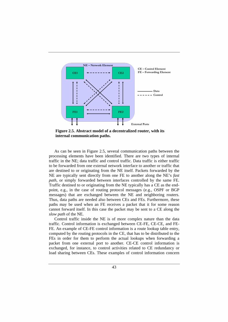
43
As can be seen in Figure 2.5, several communication paths between the
processing elements have been identified. There are two types of internal traffic in the NE; data traffic and control traffic. Data traffic is either traffic to be forwarded from one external network interface to another or traffic that are destined to or originating from the NE itself. Packets forwarded by the NE are typically sent directly from one FE to another along the NE’s fast path, or simply forwarded between interfaces controlled by the same FE. Traffic destined to or originating from the NE typically has a CE as the end-point, e.g., in the case of routing protocol messages (e.g., OSPF or BGP messages) that are exchanged between the NE and neighboring routers. Thus, data paths are needed also between CEs and FEs. Furthermore, these paths may be used when an FE receives a packet that it for some reason cannot forward itself. In this case the packet may be sent to a CE along the slow path of the NE.
Control traffic inside the NE is of more complex nature than the data traffic. Control information is exchanged between CE-FE, CE-CE, and FE-FE. An example of CE-FE control information is a route lookup table entry, computed by the routing protocols in the CE, that has to be distributed to the FEs in order for them to perform the actual lookups when forwarding a packet from one external port to another. CE-CE control information is exchanged, for instance, to control activities related to CE redundancy or load sharing between CEs. These examples of control information concern
FE1 FE2
External Ports
CE – Control ElementFE – Forwarding ElementCE1 CE2
DataControl
NE – Network Element
Figure 2.5. Abstract model of a decentralized router, with its internal communication paths.

44
the NE’s normal operation. In addition, control information is exchanged between all cooperating elements (CEs and FEs) to establish and maintain association between each other.
A decentralized modular router is in fact a distributed system, where computational tasks are spread out over multiple processing elements and databases must be shared between the processing elements. Examples of databases in the decentralized modular router model above that must be shared among CEs and FEs are routing tables, ARP tables, and traffic filter databases.
In general, the shared database in a distributed system can either be centralized or distributed over the elements using the database. A centralized database is likely to be less complex to manage, but result in higher overhead due to transactions between the elements and the database. In the case of a distributed router we cannot rely on centralized databases due to performance reasons. For instance, the forwarding elements will need local copies of the routing table to be able to perform fast route lookups. This issue is emphasized in situations where the router is distributed over a larger geographical area. Thus, the communication protocol between elements in the NE must ensure that the elements in the NE always have a common and up to date view of the routing table.
2.4. System Design A distributed router, consisting of different processing elements
interconnected using an internal network, is depicted in Figure 2.6. CE functions are generally performed in software running on a general-purpose CPU. FEs can use different types of hardware depending on forwarding properties required from the system. The main types of hardware platforms available for packet forwarding are ASICs (Application-Specific Integrated Circuit), FPGAs (Field-Programmable Gate Array), network processors, and general purpose CPUs. From a performance versus flexibility perspective, ASICs can be placed in one end of the spectrum giving high performance and very limited flexibility, while general purpose processors are in the other end of the spectrum providing limited performance but a high degree of flexibility. FPGAs and network processor can be seen as more balanced tradeoffs between performance and flexibility.
There are several interesting design alternatives when it comes to building a decentralized router based on the system description above. Our approach is to use existing open source software modules and off-the-shelf hardware (such as PCs and network processor development platforms) as processing elements in the system design. Thus, we will have to modularize components rather than develop modularized components from scratch. One

45
purpose with this approach is to demonstrate that our design can be realized without building dedicated hardware.
We use the monolithic PC-based router architecture as the starting point
for the design work, and we develop internal protocols and mechanisms needed for the physical separation of different router functions and controlling the router in distributed environment. The design of the protocols for distributed router control is influenced by the ways in which internal communication takes place in an ordinary PC-based router running UNIX, as depicted in Figure 2.7.
The basic operation of such a router can be described as follows. The routing software (routing protocols, configuration tools, etc.) builds up a routing information base (RIB). The information in the RIB is condensed and communicated to the operating system kernel, where a forwarding information base (FIB) is constructed. The FIB is consulted by the kernel-level IP packet forwarder in order to forward packets from incoming to outgoing interfaces (IF).
FE1 FE2 FE3
Internal Network
FE4
CE1 CE2 CE3NE
Figure 2.6. Overview of a distributed router with eight network interfaces. It consists of three control elements and four forwarding elements.
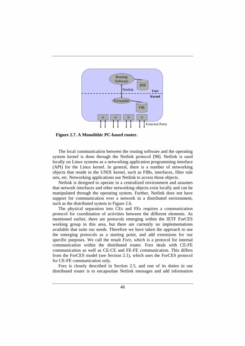
46
The local communication between the routing software and the operating
system kernel is done through the Netlink protocol [98]. Netlink is used locally on Linux systems as a networking application programming interface (API) for the Linux kernel. In general, there is a number of networking objects that reside in the UNIX kernel, such as FIBs, interfaces, filter rule sets, etc. Networking applications use Netlink to access those objects.
Netlink is designed to operate in a centralized environment and assumes that network interfaces and other networking objects exist locally and can be manipulated through the operating system. Further, Netlink does not have support for communication over a network in a distributed environment, such as the distributed system in Figure 2.6.
The physical separation into CEs and FEs requires a communication protocol for coordination of activities between the different elements. As mentioned earlier, there are protocols emerging within the IETF ForCES working group in this area, but there are currently no implementations available that suite our needs. Therefore we have taken the approach to use the emerging protocols as a starting point, and add extensions for our specific purposes. We call the result Forz, which is a protocol for internal communication within the distributed router. Forz deals with CE-FE communication as well as CE-CE and FE-FE communication. This differs from the ForCES model (see Section 2.1), which uses the ForCES protocol for CE-FE communication only.
Forz is closely described in Section 2.5, and one of its duties in our distributed router is to encapsulate Netlink messages and add information
RoutingSoftware
Netlink
FIB
RIB
Forwarder
IF
External Ports
User
Kernel
IF IF IF
Figure 2.7. A Monolithic PC-based router.
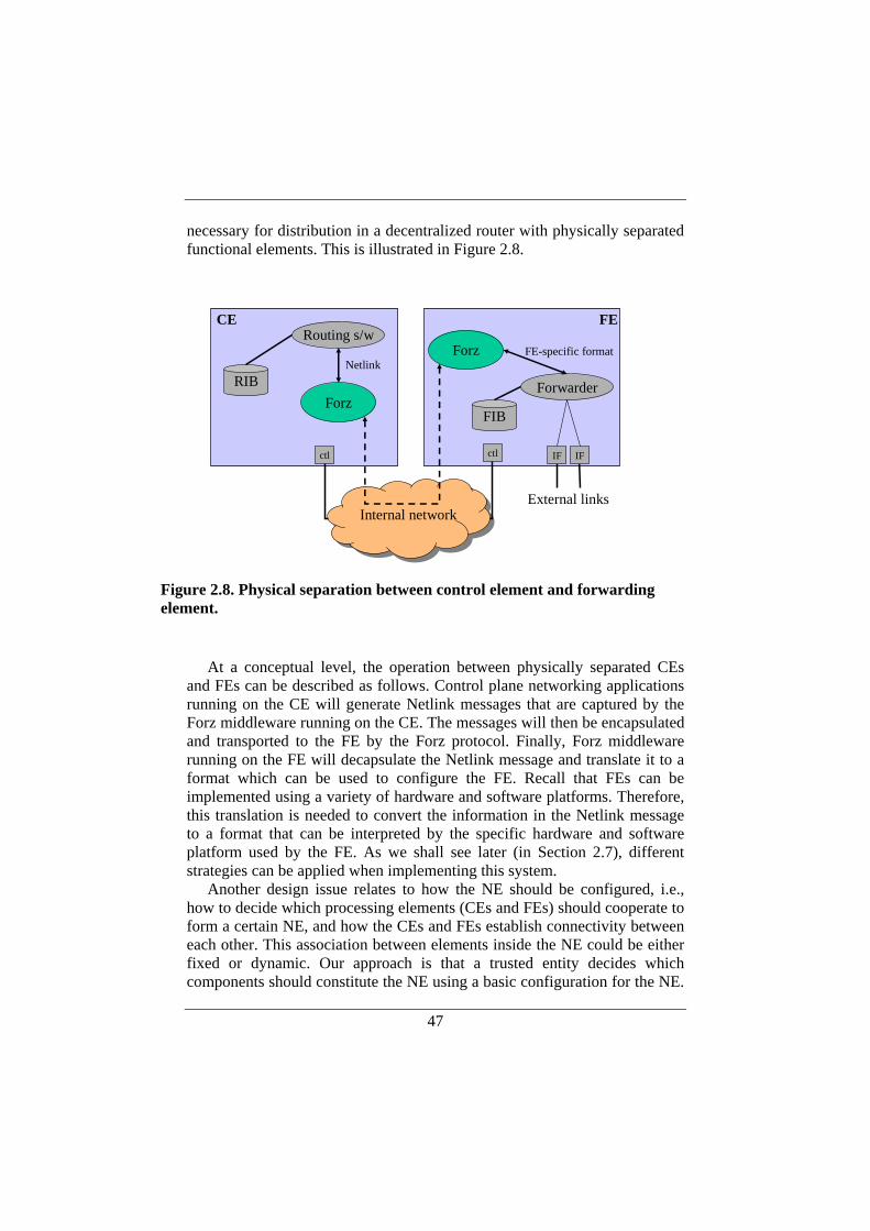
47
necessary for distribution in a decentralized router with physically separated functional elements. This is illustrated in Figure 2.8.
At a conceptual level, the operation between physically separated CEs
and FEs can be described as follows. Control plane networking applications running on the CE will generate Netlink messages that are captured by the Forz middleware running on the CE. The messages will then be encapsulated and transported to the FE by the Forz protocol. Finally, Forz middleware running on the FE will decapsulate the Netlink message and translate it to a format which can be used to configure the FE. Recall that FEs can be implemented using a variety of hardware and software platforms. Therefore, this translation is needed to convert the information in the Netlink message to a format that can be interpreted by the specific hardware and software platform used by the FE. As we shall see later (in Section 2.7), different strategies can be applied when implementing this system.
Another design issue relates to how the NE should be configured, i.e., how to decide which processing elements (CEs and FEs) should cooperate to form a certain NE, and how the CEs and FEs establish connectivity between each other. This association between elements inside the NE could be either fixed or dynamic. Our approach is that a trusted entity decides which components should constitute the NE using a basic configuration for the NE.
Routing s/w
Forz
IF IF
Forz
CE FE
ctl
Netlink
ctl
FIB
RIB Forwarder
FE-specific format
External linksInternal network
Figure 2.8. Physical separation between control element and forwarding element.

48
However, CEs and FEs configured to belong to a certain NE may join and leave the NE in a dynamic fashion. Thus, our router model can be described as a loosely coupled system. We believe that this will lead to a design that is both robust (the NE can continue to operate even if a certain element breaks) and flexible (elements can be added and deleted during operation of the NE).
Forwarding and control elements that are configured to belong to the same NE can be started and stopped at arbitrary times and independently of each other. The typical scenario is that a CE is started, begins to announce itself and waits for announcements from other elements. Then an FE is booted and the CE and FE will associate with each other, verifying that they belong to the same NE. The CE will probe the FE for its network interfaces (type of interface, number of interfaces etc). The CE will register the information and start configuring the interfaces on the remote FE. A CE that is responsible for IP routing will then start to exchange routing protocol messages with neighbor routers and build up a routing table.
Routing table entries will be distributed to the forwarding elements, which will build local forwarding tables based on this information. There are no restrictions on the start-up order among the elements. For instance, a forwarding element of an NE can be started when the rest of the system has been up and running for a while. When this forwarding element has identified itself and associated with the other elements its network interfaces will be configured by a CE, and the current state of the databases will be transferred to the forwarding element.
2.5. The Internal Protocols—Forz Forz is a protocol with three main parts: association, configuration, and
data transfer. In the association part of the protocol, the constituting elements establish the communication and declare their capabilities.
The purpose of the configuration part is to convey configuration commands and event notifications. For example, if a CE computes new routes for a destination, this information is conveyed to the FEs to be installed in the forwarding tables. Correspondingly, if a physical link on a FE fails, the CEs need to be notified.
The Forz configuration messages are based on the Netlink protocol. More specifically, the networking objects that reside in the Linux kernel, such as routing tables, interfaces, filter rule-sets, etc, are managed and controlled from user space using Netlink.
The data transfer part, finally, deals with the switching of data packets between FEs, and with data packets that are either destined to or originating from the NE itself. Ideally, an FE should be capable of making local forwarding decisions so that packets can be forwarded along the fast path.
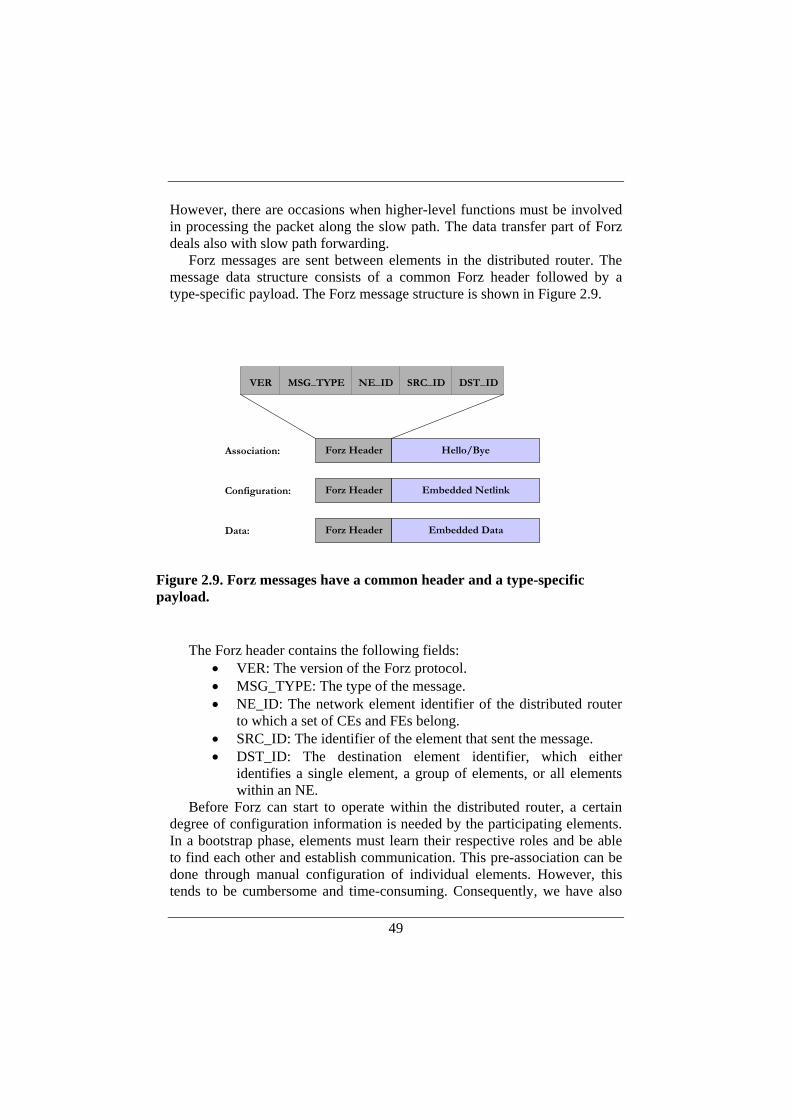
49
However, there are occasions when higher-level functions must be involved in processing the packet along the slow path. The data transfer part of Forz deals also with slow path forwarding.
Forz messages are sent between elements in the distributed router. The message data structure consists of a common Forz header followed by a type-specific payload. The Forz message structure is shown in Figure 2.9.
The Forz header contains the following fields:
• VER: The version of the Forz protocol. • MSG_TYPE: The type of the message. • NE_ID: The network element identifier of the distributed router
to which a set of CEs and FEs belong. • SRC_ID: The identifier of the element that sent the message. • DST_ID: The destination element identifier, which either
identifies a single element, a group of elements, or all elements within an NE.
Before Forz can start to operate within the distributed router, a certain degree of configuration information is needed by the participating elements. In a bootstrap phase, elements must learn their respective roles and be able to find each other and establish communication. This pre-association can be done through manual configuration of individual elements. However, this tends to be cumbersome and time-consuming. Consequently, we have also
Forz Header Embedded NetlinkConfiguration:
Forz Header Embedded DataData:
Forz Header Hello/ByeAssociation:
VER MSG_TYPE NE_ID SRC_ID DST_ID
Figure 2.9. Forz messages have a common header and a type-specific payload.
50
experimented with a management tool, called network element manager (NEM), which performs the initial configuration of the elements forming a distributed router [40]. With it, we can associate individual elements with the network element, assign control addresses and interfaces for the internal networks, as well as control logging and debugging.
NEM communicates using a management multicast group address. Therefore, the elements need only configure this multicast address to be able to bootstrap the system. All other pre-association configuration information is conveyed via NEM.
In the following sections the different parts of the Forz protocol are described.
2.5.1. Association After the pre-association procedure, CEs and FEs can enter the
association part of the Forz protocol with the main purpose to dynamically setup the internal relations within the distributed router. The Forz association is relatively simple. It consists of a HELLO protocol that periodically transmits the status of an element to the rest of the group over IP multicast. The HELLO protocol supports the following features:
• Ability to join and leave a network element. • Announcement of addresses for internal control and data
networks. • Announcement of the element capabilities.
When a new element is started, its Forz database is initially empty. When the element joins an existing NE, it sends a HELLO message to the control multicast address. This causes all other elements to extend their databases to include this new participating element. The initial HELLO also triggers HELLO messages from all existing NE members, thus enabling the new element to extend its own database until it is complete—i.e., it contains all active members of the NE.
The type-specific part of the HELLO message contains the protocol element’s IP address on the internal control and data networks respectively.
The HELLO message also carries capability information so that a CE or FE can inform other participants of the NE about its own capabilities. Different CEs may have different functionalities and an FE must have a way of knowing which CE is responsible for what functions. As an example, routing messages (BGP or OSPF) may be sent to a CE responsible for routing and ARP (Address Resolution Protocol) messages to another CE responsible for address resolution. When an FE receives a packet that needs local delivery to a CE, the capability information can be used to pick the appropriated CE for local delivery.
51
Moreover, different FEs may have different forwarding capabilities. Some FEs may only be capable of performing plain IPv4 forwarding while others may have support for classification, quality of service, and traffic shaping. A CE controlling an FE must be aware of such capabilities so that it can perform appropriate configuration of the FE.
When a protocol element is brought down in a controlled manner, it will send a BYE message telling the remaining protocol elements that it has left the NE. If a protocol element crashes, the absence of HELLO messages (heartbeats) will cause the remaining participants in the NE to take the appropriate actions.
Forz association allows for dynamic changes in the element configuration so that CEs and FEs can join or leave the NE at any time during operation.
2.5.2. Configuration Forz configuration is based on the Netlink protocol. Netlink specifies an
extensive set of messages for various IP services. A simple example of an IP service is the traditional IPv4 forwarding where the control plane provides the routing functionality, and the forwarding plane provides the actual forwarding of packets from one link to another. Netlink specifies the messages that are needed to communicate information between control plane and forwarding plane. There are many IP services defined in Netlink, and the Netlink services that are distributed by the current version of the Forz protocol are the following:
• Network interface service • IP address service • Network route service • Neighbor setup service
The network interface service provides the ability to create, remove, or get information about a network interface. Examples of information communicated by this service are type of link device, device flags, interface name, hardware address, etc. The related Netlink messages that are distributed by Forz are:
• NEWLINK: to create network interface information • DELLINK: to remove network interface information • GETLINK: to get network interface information
The IP address service provides the ability to add, remove, or receive information about an IP address of an interface. Examples of information communicated by this service are IP address, broadcast address, address flags, etc. The related Netlink messages are:
• NEWADDR: to create IP address information
52
• DELADDR: to remove IP address information • GETADDR: to get IP address information
The network router service provides the ability to create, remove, or receive information about a route. Examples of information communicated by this service are prefix (destination address and address mask), next hop address, type of route, etc. The related Netlink messages are:
• NEWROUTE: to create route information • DELROUTE: to remove router information • GETROUTE: to get route information
The neighbor setup service provides the ability to add, remove, or receive information about a neighbor table entry, for instance an ARP table entry. Examples of information communicated by this service are IP address and MAC address. The related Netlink messages are
• NEWNEIGH: to create neighbor information • DELNEIGH: to remove neighbor information • GETNEIGH: to get neighbor information
Forz configuration messages encapsulate Netlink messages, and accordingly Forz follows the original Netlink protocol behavior rather closely. However, configuration messages need to be reliably transmitted in order not to violate the underlying Netlink semantics. For example, if a CE changes a route and only succeeds in transmitting it to a subset of FEs, it may cause an inconsistent internal state. One way to deal with this issue is to use reliable transport protocols for configuration messages. This is further discussed in Section 2.6 and in Chapter 3.
Further, since Forz is distributed and Netlink is not, several changes to the Netlink parameters have been made. This includes mapping network interface names and indexes from local to global scope. That is, a Netlink message may indicate an interface, but a Forz message also needs to indicate to which FE the interface belongs. During execution of the Forz protocol, an element database is constructed to keep track of the participants forming the NE. This element database is consulted in order to map local interface information to a global scope and vice versa.
As an example, consider the situation when a CE and an FE has established association within an NE. The FE will then report its interfaces through a Forz-encapsulated NEWLINK message for each external interface on that FE. The NEWLINK message includes the name and the hardware address of each interface.
The name of the external interface is formed by concatenating the name of the FE and the local interface name. Thus, for example, the eth0 interface of FE2 is named fe2:eth0. The element identifier is concatenated with the local interface index to form a global interface index that can be used
53
universally within the distributed router. When the NEWLINK messages arrive at the CE, the interfaces will appear in networking applications for the distributed router that executes on the CE.
When a CE has discovered a new external interface, the CE can assign an address to that interface. In our case, we use standard tools like the Zebra routing daemon [34], “ifconfig”, and “ip”. This will result in a NEWADDR message being captured by the Forz protocol and propagated to the other elements. The FEs will install the new addresses and ensure that incoming packets destined to that address are forwarded to the CE. Note that this applies to all FEs, not only the FE where the physical interface actually resides.
In a similar fashion, routes set by a configuration tool, such as the “route” command or by a routing daemon, result in a NEWROUTE message being captured by Forz and sent to all other elements. Upon reception of such a message, the FEs will install the corresponding route in their FIBs. The FIB installation may require some conversion of the routing information depending on whether the outgoing network interface is a local interface or not. If not, packets forwarded onto the network interface need to be relayed to the corresponding outgoing FE over the internal data network.
2.5.3. Data Transfer The main purpose of the data transfer part of Forz is to transfer IP packets
that are either destined to the NE itself or originating from the NE. Such IP packets may have to be transported over the CE-FE interface. A typical example of this is when a CE exchanges routing protocol messages (e.g., OSPF or BGP messages) with a remote router. An incoming IP packet that is to be terminated in a CE will be received by an FE, encapsulated in a Forz data message, and sent to the appropriate CE. An outgoing packet originating from a CE will be encapsulated in a Forz data message, sent to the appropriate FE, which will decapsulate the IP packet and forward it onto the external link.
The data transfer part of Forz could also be used to switch packets between FEs—when the incoming and outgoing port of a packet reside on different FEs, the packet needs to be transported across the internal network. However, it may be argued that Forz level encapsulation can suffer from poor performance due to application-level manipulation of data. Therefore, Forz level encapsulation of data may not be suitable for data traffic that is forwarded between FEs in the distributed router. In contrast, control traffic to or from CEs is not likely to be as sensitive to the limited performance potentially caused by application level tunneling. Therefore, Forz level encapsulation of data may be sufficient as a carrier of IP packets to/from the
54
router’s control plane. As such, Forz level encapsulation is advantageous from a simplicity perspective—it can be implemented entirely at the application level, without any modifications at the operating system level.
It should be noted that some form of encapsulation or tunneling is needed when transferring data over the internal network in the general case. A particular problem that occurs is that the IP header of the packet cannot be used for routing over the internal network. This is further discussed in the following section.
2.6. Internal Network The design of the internal network for control and data traffic between
elements opens up different alternatives. The requirement on the internal network is that it should scale to a large number of FEs and CEs as well as to a geographical area that goes beyond a regular multi-chassis solution. This could be fulfilled, for instance, by a layer 2 network (like Ethernet) or by an IP network.
Our design choice is to use an IP network internally, which will give us the possibility to use existing well-known APIs and transport protocols (TCP, UDP etc.) to implement the protocols for internal communication between modularized components (CEs and FEs) in the NE. Further, our design uses two internal networks—one control network for internal control traffic and one data network for internal data traffic. The reasons behind that decision are that these networks should be dimensioned differently. The data network should be of very high capacity and possible to extend if more forwarding elements are added to the system while the capacity requirements on the control network are more relaxed. The separation of data and control will prevent control traffic from being starved out by large volumes of data passing through the NE. An alternative method could be to use one single network and devote a part of the capacity to control traffic or give a higher priority to control traffic.
Another issue regarding internal communication between the elements constituting the NE concerns the choice of transport protocol. For simplicity, an attractive choice is to use UDP, which also gives the possibility to use IP multicast. However, there are many different types of information that are communicated between the elements. Some information may require reliable transport (e.g., route updates) and others may prefer timeliness rather than reliability (e.g., heartbeat messages). There may even be information that is sent from one to many that still requires reliable transport. The conclusion is that we cannot rely solely on UDP and IP multicast. Some information will be communicated internally over TCP and possibly also over a reliable multicast transport protocol.
55
The choice of an internal IP network opens up interesting challenges related to forwarding of packets internally. The internal IP network may be a routed multi-hop network, and the internal routing must thus be separated from the external routing. If IP addresses are used for internal addressing, those IP addresses have to be taken from a different address space than is used for the external routing. Further, an FE that receives a packet on an external interface cannot simply process the packet and forward it onto the internal IP network. For example, TTL should only be decremented by one during the transfer over the internal network from ingress FE to egress FE regardless of how the packet is forwarded internally inside the NE.
For these reasons, packets need to be encapsulated before they are transmitted across the internal network. There are several standardized ways to hide the internal IP network to the external world, through the use of e.g., VLAN 802.1Q, MPLS, or IP in IP tunnels.
The encapsulation of packets transported from ingress to egress FE is also depending on the design of the address lookup operation. Simply put, the lookup operation must return the next hop router’s MAC address and the outgoing interface to forward the packet properly.
There are different ways to partition the lookup operation between ingress FE and egress FE. One alternative is to let the ingress FE perform the complete lookup. In this case, the ingress FE must communicate the result of the lookup (i.e., outgoing interface and next hop MAC address in the simplest case) along with the actual packet when it is forwarded internally to the egress FE. The egress FE can then transmit the packet on the outgoing interface without being involved in the lookup operation. This means that the complete forwarding decision could be made in one single lookup operation, which may be advantageous for efficiency reasons.
An alternative to performing complete lookup on the ingress FE could be to let the ingress FE only look up the egress FE, and leave it to the egress FE to complete the forwarding decision by performing a new lookup resulting in outgoing interface and next hop MAC address. The advantage is that no information must be communicated along with the packet from ingress FE to egress FE meaning that a raw data transfer of the packet can be done internally. The drawback is that at least two lookup operations must be done to make a complete forwarding decision.
The lookup operation used as an example here is the simplest possible. Normally, routers are capable of performing much more advanced lookups based on information in link, network, and transport level headers. The conclusion is that ingress and egress FE may have to cooperate to do a complete forwarding decision and that it must be possible to communicate information from ingress to egress FE along with the packet itself.
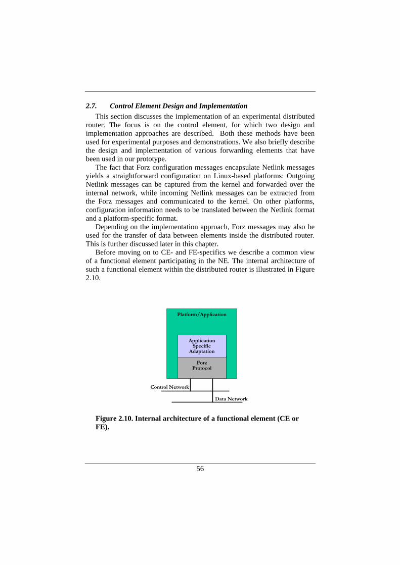
56
2.7. Control Element Design and Implementation This section discusses the implementation of an experimental distributed
router. The focus is on the control element, for which two design and implementation approaches are described. Both these methods have been used for experimental purposes and demonstrations. We also briefly describe the design and implementation of various forwarding elements that have been used in our prototype.
The fact that Forz configuration messages encapsulate Netlink messages yields a straightforward configuration on Linux-based platforms: Outgoing Netlink messages can be captured from the kernel and forwarded over the internal network, while incoming Netlink messages can be extracted from the Forz messages and communicated to the kernel. On other platforms, configuration information needs to be translated between the Netlink format and a platform-specific format.
Depending on the implementation approach, Forz messages may also be used for the transfer of data between elements inside the distributed router. This is further discussed later in this chapter.
Before moving on to CE- and FE-specifics we describe a common view of a functional element participating in the NE. The internal architecture of such a functional element within the distributed router is illustrated in Figure 2.10.
Platform/Application
Control Network
Data Network
ApplicationSpecific
Adaptation
ForzProtocol
Figure 2.10. Internal architecture of a functional element (CE or FE).
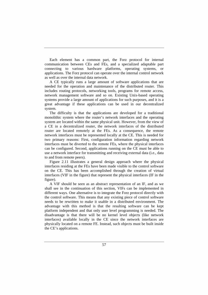
57
Each element has a common part, the Forz protocol for internal
communication between CEs and FEs, and a specialized adaptable part connecting to various hardware platforms, operating systems, or applications. The Forz protocol can operate over the internal control network as well as over the internal data network.
A CE typically runs a large amount of software applications that are needed for the operation and maintenance of the distributed router. This includes routing protocols, networking tools, programs for remote access, network management software and so on. Existing Unix-based operating systems provide a large amount of applications for such purposes, and it is a great advantage if these applications can be used in our decentralized system.
The difficulty is that the applications are developed for a traditional monolithic system where the router’s network interfaces and the operating system are located within the same physical unit. However, from the view of a CE in a decentralized router, the network interfaces of the distributed router are located remotely at the FEs. As a consequence, the remote network interfaces must be represented locally at the CE. This is needed for two primary reasons: First, configuration information regarding network interfaces must be diverted to the remote FEs, where the physical interfaces can be configured. Second, applications running on the CE must be able to use a network interface for transmitting and receiving external data (i.e., data to and from remote peers).
Figure 2.11 illustrates a general design approach where the physical interfaces residing at the FEs have been made visible to the control software on the CE. This has been accomplished through the creation of virtual interfaces (VIF in the figure) that represent the physical interfaces (IF in the figure).
A VIF should be seen as an abstract representation of an IF, and as we shall see in the continuation of this section, VIFs can be implemented in different ways. One alternative is to integrate the Forz protocol directly with the control software. This means that any existing piece of control software needs to be rewritten to make it usable in a distributed environment. The advantage with this method is that the resulting software can be kept platform independent and that only user level programming is needed. The disadvantage is that there will be no kernel level objects (like network interfaces) available locally in the CE since the network interfaces are physically located on a remote FE. Instead, such objects must be built inside the CE’s applications.
58
In a user level CE implementation it is not possible to use the kernel level
TCP/IP protocol stack communication with external peers (i.e., outside the NE itself). The reason for this is that internal and external IP routing and addressing are separated. We let the BGP routing protocol serve as an example of this situation:
The BGP daemon runs on a CE and communicates over TCP with neighboring routers outside the NE. The BGP daemon expects that the physical interfaces are present locally and that packets to/from the daemon go through the kernel level TCP/IP stack. Instead, user space interface objects must be created and packets to/from the BGP daemon have to go through the user level Forz software. This means that a user level TCP/IP stack is needed, since the kernel level TCP/IP stack is only aware of the NE’s internal IP network. This is illustrated in Figure 2.12.
An alternative method is to create virtual interfaces in the operating system kernel and to let these virtual interfaces serve as local representations of the remote physical interfaces. Such an approach allows the control applications to remain unchanged and to operate on kernel level objects associated with the virtual interfaces. This alternative may be more challenging from a programming perspective and also result in a platform-dependent implementation. Porting the kernel level software from one platform to another is not likely to be straightforward. However, it is a great advantage to be able to use existing control applications without modifications.
FIB IF
IF
FIB IF
IF
FIB IF
IF
ForzProtocolCE
FEs
forw
forw
forw
zebra
netstat
VIF
VIF
VIF
VIF
VIF
RIBVIF
ifconfig IP
Figure 2.11. General view of the CE with FEs.
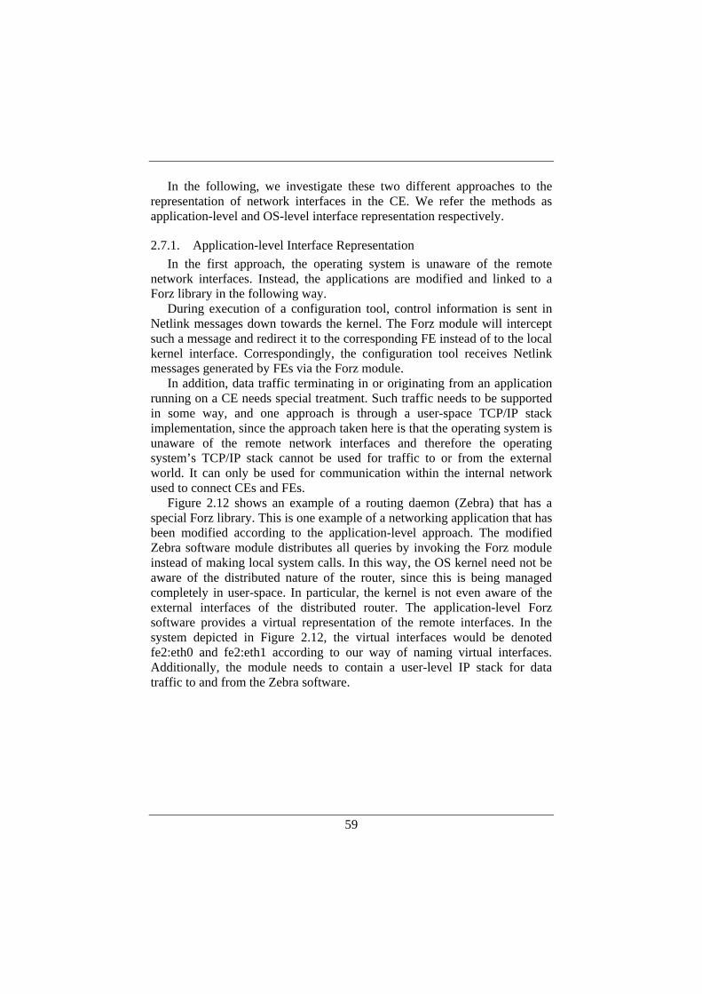
59
In the following, we investigate these two different approaches to the representation of network interfaces in the CE. We refer the methods as application-level and OS-level interface representation respectively.
2.7.1. Application-level Interface Representation In the first approach, the operating system is unaware of the remote
network interfaces. Instead, the applications are modified and linked to a Forz library in the following way.
During execution of a configuration tool, control information is sent in Netlink messages down towards the kernel. The Forz module will intercept such a message and redirect it to the corresponding FE instead of to the local kernel interface. Correspondingly, the configuration tool receives Netlink messages generated by FEs via the Forz module.
In addition, data traffic terminating in or originating from an application running on a CE needs special treatment. Such traffic needs to be supported in some way, and one approach is through a user-space TCP/IP stack implementation, since the approach taken here is that the operating system is unaware of the remote network interfaces and therefore the operating system’s TCP/IP stack cannot be used for traffic to or from the external world. It can only be used for communication within the internal network used to connect CEs and FEs.
Figure 2.12 shows an example of a routing daemon (Zebra) that has a special Forz library. This is one example of a networking application that has been modified according to the application-level approach. The modified Zebra software module distributes all queries by invoking the Forz module instead of making local system calls. In this way, the OS kernel need not be aware of the distributed nature of the router, since this is being managed completely in user-space. In particular, the kernel is not even aware of the external interfaces of the distributed router. The application-level Forz software provides a virtual representation of the remote interfaces. In the system depicted in Figure 2.12, the virtual interfaces would be denoted fe2:eth0 and fe2:eth1 according to our way of naming virtual interfaces. Additionally, the module needs to contain a user-level IP stack for data traffic to and from the Zebra software.
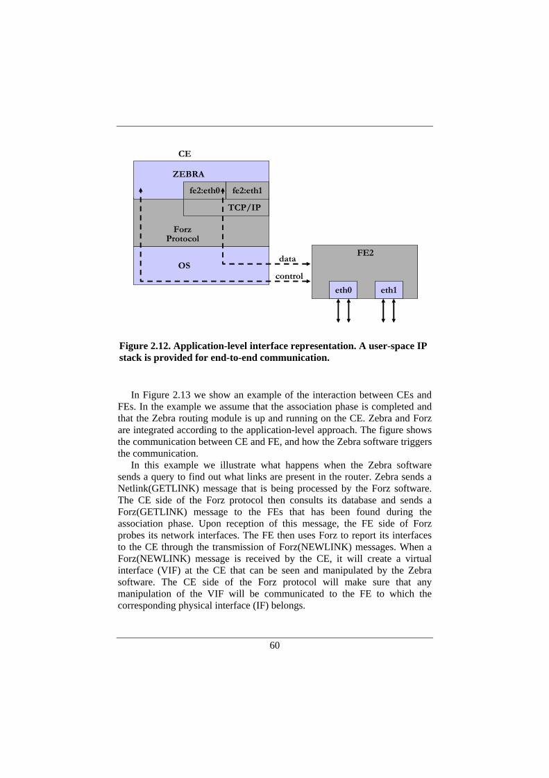
60
In Figure 2.13 we show an example of the interaction between CEs and
FEs. In the example we assume that the association phase is completed and that the Zebra routing module is up and running on the CE. Zebra and Forz are integrated according to the application-level approach. The figure shows the communication between CE and FE, and how the Zebra software triggers the communication.
In this example we illustrate what happens when the Zebra software sends a query to find out what links are present in the router. Zebra sends a Netlink(GETLINK) message that is being processed by the Forz software. The CE side of the Forz protocol then consults its database and sends a Forz(GETLINK) message to the FEs that has been found during the association phase. Upon reception of this message, the FE side of Forz probes its network interfaces. The FE then uses Forz to report its interfaces to the CE through the transmission of Forz(NEWLINK) messages. When a Forz(NEWLINK) message is received by the CE, it will create a virtual interface (VIF) at the CE that can be seen and manipulated by the Zebra software. The CE side of the Forz protocol will make sure that any manipulation of the VIF will be communicated to the FE to which the corresponding physical interface (IF) belongs.
CE
ZEBRA
data
control
FE2
ForzProtocol
OS
eth0 eth1
fe2:eth0 fe2:eth1
TCP/IP
Figure 2.12. Application-level interface representation. A user-space IP stack is provided for end-to-end communication.
61
In Figure 2.13 we also show how Zebra sets up a new route that has been
configured or computed by a routing protocol. Zebra will then generate a Netlink(NEWROUTE) message that will be snooped by the Forz module. The CE will set this entry in its RIB (Routing Information Base) and the Forz protocol will communicate the route to the correct FE through a Forz(NEWROUTE) message. Finally, the FE will update the FIB that is built up in the forwarding element.
The advantage with the application-level approach is the flexibility of the application: it can be ported to any operating system without kernel modifications. The disadvantages are that all applications need to be modified to be aware of the non-local interfaces, and that a user-space TCP/IP protocol stack must be supplied.
2.7.2. OS-level Interface Representation With this approach, the goal is to keep the CE applications unmodified,
which requires that the operating system is aware of the network interfaces
CE
Forz(GETLINK)
Forz(NEWLINK)Forz(NEWLINK)
Forz(NEWROUTE)
Report IFReport IF
Set FIB entry
Create VIFCreate VIF
FEForz(ASSOCIATION)
Zebra: ”find links”
Zebra: ”set route”
.
.
.
.
Set RIB entry
Figure 2.13. Example of Forz message exchange between CE and FE using the application-specific interface representation.
62
remotely located at the FEs so that the native IP stack can be used for communication between FEs and CEs. This is achieved in the following way.
For each remote interface on an FE, a corresponding network interface object is created in the CE operating system. These interface objects are instantiated as tunnel interfaces, i.e., non-physical software-based interface structures. Thus, the tunnel interfaces are OS-level representations of the remote interfaces, and they are also named according to our interface naming conversions (e.g., fe2:eth0). These interface structures can be used by any CE application in the same fashion as ordinary local network interfaces.
Compared to the application-level approach, the Forz module used here is augmented with functionality to detect Netlink messages generated by the OS kernel. When a CE application performs an operation that changes the state of an interface, the kernel announces this state change via a Netlink message. The Forz module detects those messages from the kernel and encapsulates them in Forz messages for internal distribution to CEs and FEs. The modus operandi is similar for other networking objects: for example the installation of a new route in the kernel results in Netlink message that reflects the state change. The OS-level representation of network interfaces, including state changes via Netlink, is illustrated in Figure 2.14. Again, we use Zebra as an example of a networking application, and we also show two companion processes to Zebra running the routing protocols OSPF and BGP respectively. No modifications are done to the applications.
The fact that Forz detects changes in the networking objects makes protocol operation slightly different compared to the application-level approach (see Figure 2.13), where interfaces are created when Zebra probes the system for available interfaces. With the OS-level approach, this will not work. The explanation is as follows:
Assume that Zebra sends a Netlink(GETLINK) to query the system about network interfaces. Such a Netlink message will not cause any state changes in any networking objects, and will therefore not be seen by the Forz module. Accordingly, another procedure must be used to create the virtual interfaces. It cannot be done as a consequence of Zebra generating Netlink(GETLINK) interfaces. Instead, Forz(NEWLINK) messages are sent spontaneously when the FE is started as well as when a new CE is detected through a Forz(HELLO) message. When the CE side of Forz receives the Forz(NEWLINK) message, the corresponding Netlink message is created and sent down to the OS kernel. This will cause the creation of the tunnel interface representing the remotely located physical interface. This change is then reflected by the kernel through a Netlink(NEWLINK) message which can be seen by the Zebra daemon.
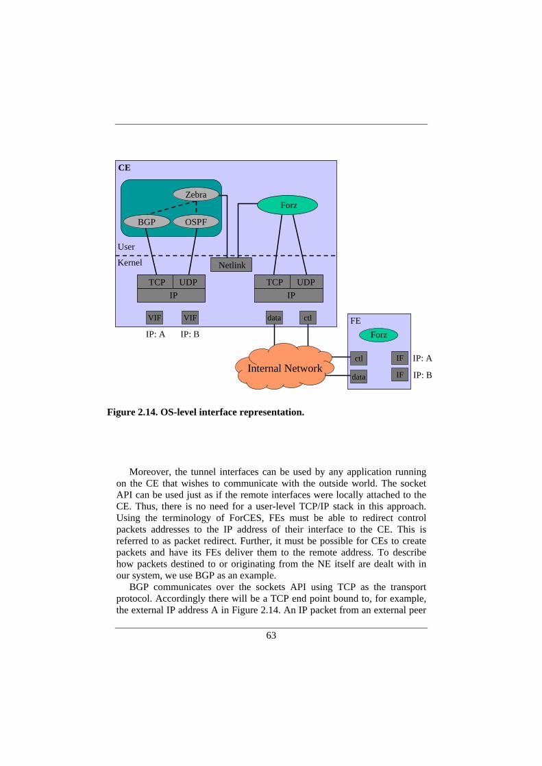
63
Moreover, the tunnel interfaces can be used by any application running
on the CE that wishes to communicate with the outside world. The socket API can be used just as if the remote interfaces were locally attached to the CE. Thus, there is no need for a user-level TCP/IP stack in this approach. Using the terminology of ForCES, FEs must be able to redirect control packets addresses to the IP address of their interface to the CE. This is referred to as packet redirect. Further, it must be possible for CEs to create packets and have its FEs deliver them to the remote address. To describe how packets destined to or originating from the NE itself are dealt with in our system, we use BGP as an example.
BGP communicates over the sockets API using TCP as the transport protocol. Accordingly there will be a TCP end point bound to, for example, the external IP address A in Figure 2.14. An IP packet from an external peer
IF
IF
FEForz
BGP
VIF VIF
OSPF
CE
data
TCP UDPIP
TCP UDPIP
User
Kernel
IP: A IP: B
IP: A
IP: B
ctl
Zebra
Netlink
Forz
ctl
dataInternal Network
Figure 2.14. OS-level interface representation.
64
destined to the BGP process through IP address A will be handled as follows. The FE will note that the packet requires local delivery to the CE since it is destined to one of its own interface addresses. The packet will thus be redirected to the Forz module, which will encapsulate the IP packet in a Forz DATA message and send it to the CE. Thus, the IP packet is tunneled over the internal data network in an application-level Forz tunnel. When reaching the tunnel end point at the CE, the packet will be decapsulated and redirected to the VIF with IP address A. Thereafter, the packet will travel up the TCP/IP stack to finally reach the BGP process through the sockets API. From the perspective of BGP, it will look exactly as if the packet arrived on a physical interface with IP address A. Packets that are created by the BGP process and sent to an external BGP peer will travel down the TCP/IP stack to the corresponding outgoing VIF. In our example this is the VIF configured with IP address A. The Forz module will read the packet from the VIF, encapsulate it in a Forz DATA messages and send it to the FE responsible for the physical interface with IP address A. The FE side of the Forz protocol decapsulates the IP packet and delivers it to the external network.
The primary advantage with this OS-level approach is that it is a general solution that allows existing applications to be used without changes. We further believe that the OS-level interface representation is suitable also for Unix flavors not using Netlink. For instance, BSD Unix uses routing sockets that could be eavesdropped similar to the way we deal with Netlink messages in our current implementation.
However, with this approach there is no distinction in the CE operating system between local and remote interfaces—they all appear as local interfaces. Therefore an additional level of configuration information is needed, in order to specify whether an interface is local or remote.
2.8. Supporting Multiple Control Elements Our prototype implementation supports the use of multiple CEs within
the same NE. For comparison, it should be mentioned that the ForCES framework allows the use of multiple CEs, but that it is outside the scope of the current standardization work.
Multiple CEs in our distributed router means that networking applications can be run on different CEs in the system and they will receive a common view of the state within the networking element. For instance, when an application on a CE sets the IP address of an external interface residing on an FE, this state change will be reflected on all other CEs associated with the same NE. This section describes how CEs, FEs and the Forz protocol support the use of multiple control elements. The description assumes the
65
OS-level system implementation approach described in the previous section (Section 2.7.2), but there is nothing that prevents a corresponding support for the application-level approach (described in Section 2.7.1).
The implementation is currently limited to the following networking objects: network interfaces, IP addresses, and routing table entries.
2.8.1. Network Interfaces—Link Objects When an FE is started it probes its own external interfaces. Each interface
has an index number, the interface index, which is unique only within the FE. The Forz module will therefore concatenate this local index with the FE ID to form an index which is “globally” unique within the NE. Thereafter, a Forz(NEWLINK) message will be sent to all CEs to inform them about the interfaces residing at the FE. The procedure is the same when an FE receives the first Forz(HELLO) from a new CE. There are no requirements on the order in which CEs and FEs should be started. Whenever a new FE is started it will report its interfaces to all available CEs. Whenever a new CE is started, this will trigger the available FEs to report their interfaces.
Assume that a CE brings up a network interface residing on an FE by configuring the corresponding VIF on the CE. This will result in a state change on the FE, which in turn will cause a Forz(NEWLINK) message to be sent from the FE to all CEs within the NE. Thus, all CEs will be updated with the new interface status and their virtual representations of the physical interface will correspondingly be configured to reflect the update.
2.8.2. IP Addresses—Address Objects The IP address object is dealt with in a fashion similar to the link object.
When a CE configures an interface with an IP address (by assigning an IP address to the corresponding VIF), this will result in a Forz(NEWADDR) being sent from the CE to the FE hosting the physical interface. When the address is configured, this state change will cause a Forz(NEWADDR) to be sent from the FE to all CEs within the NE to inform them about the state change.
As in the case of link objects, an FE will communicate all its configured IP addresses to a CE upon reception of the first Forz(HELLO) message from a particular CE.
2.8.3. Routing Table Entries—Route Objects Route objects are treated somewhat differently than link and address
objects when it comes to communicating state changes between CEs and FEs. IP addresses or an interface flags are typically communicated from a CE to a particular FE, and the state change in the FE is reflected to other CEs
66
through a Forz message. When a CE computes a new best route, it will update its local RIB and its kernel-level FIB. In addition, every local FIB that is managed by an FE must be updated with this new best route. If every FE that received the new route were to communicate this state change to the CEs, each CE could potentially receive a large amount of messages at the same time. Considering the scaling requirements of supporting hundreds of FEs, such a message explosion is not desirable.
Therefore, a Forz(NEWROUTE) that is distributed to all FEs within the NE is also sent to all other CEs within the NE so that these can install the new route in their local copies of the routing table. Accordingly, all CEs will have a common view of the routing table.
The Netlink protocol allows applications to specify if they request an acknowledgment of a NEWROUTE message to confirm that the route really has been installed in the forwarding table. Such a request for acknowledgment is relayed to the FEs when the Forz protocol conveys the Netlink messages. However, this will require a CE to process one acknowledgment from every FE when a new route has been installed in the FEs.
The CE side of the Forz protocol filters out Netlink messages that are generated as a result of state changes caused by Forz itself. Consider a CE, CE1, that receives a Forz(NEWROUTE) from another CE, CE2: when CE1 decapsulates the Netlink message and forwards it down to the operating system kernel, this will result in a state change that causes a state change in the routing table. Therefore, the kernel will generate a NEWROUTE message that will be seen by networking applications as well as by the Forz software module. To avoid that this Netlink message is distributed again by the Forz protocol, Forz will discard NEWROUTES that are a result of its own actions.
2.9. Forwarding Element Design and Implementation The software architecture of an FE may differ depending on the
underlying hardware platform. To support the use of different hardware and software platforms as well as different CE-FE protocols (e.g., it should be possible to replace the Forz protocol implementation with a future ForCES protocol implementation) FE implementations should be divided into protocol-specific parts, generic parts, and platform-specific parts. The general structure of an FE is depicted in Figure 2.15.
The Forz protocol module is responsible for processing of incoming protocol messages and generation of outgoing protocol messages. The FE-generic level maintains generic data structures and support functions that are
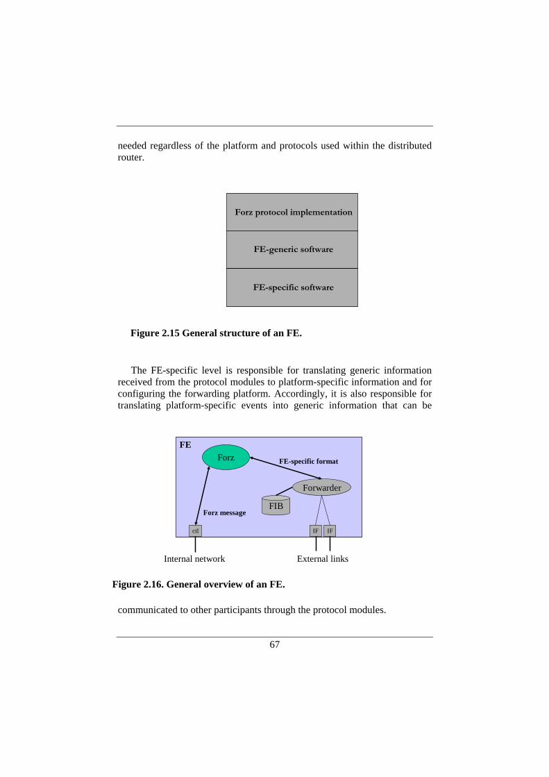
67
needed regardless of the platform and protocols used within the distributed router.
The FE-specific level is responsible for translating generic information
received from the protocol modules to platform-specific information and for configuring the forwarding platform. Accordingly, it is also responsible for translating platform-specific events into generic information that can be
communicated to other participants through the protocol modules.
Forz protocol implementation
FE-generic software
FE-specific software
Figure 2.15 General structure of an FE.
IF IF
ForzFE
FIB
Forwarder
External links
ctl
Internal network
FE-specific format
Forz message
Figure 2.16. General overview of an FE.
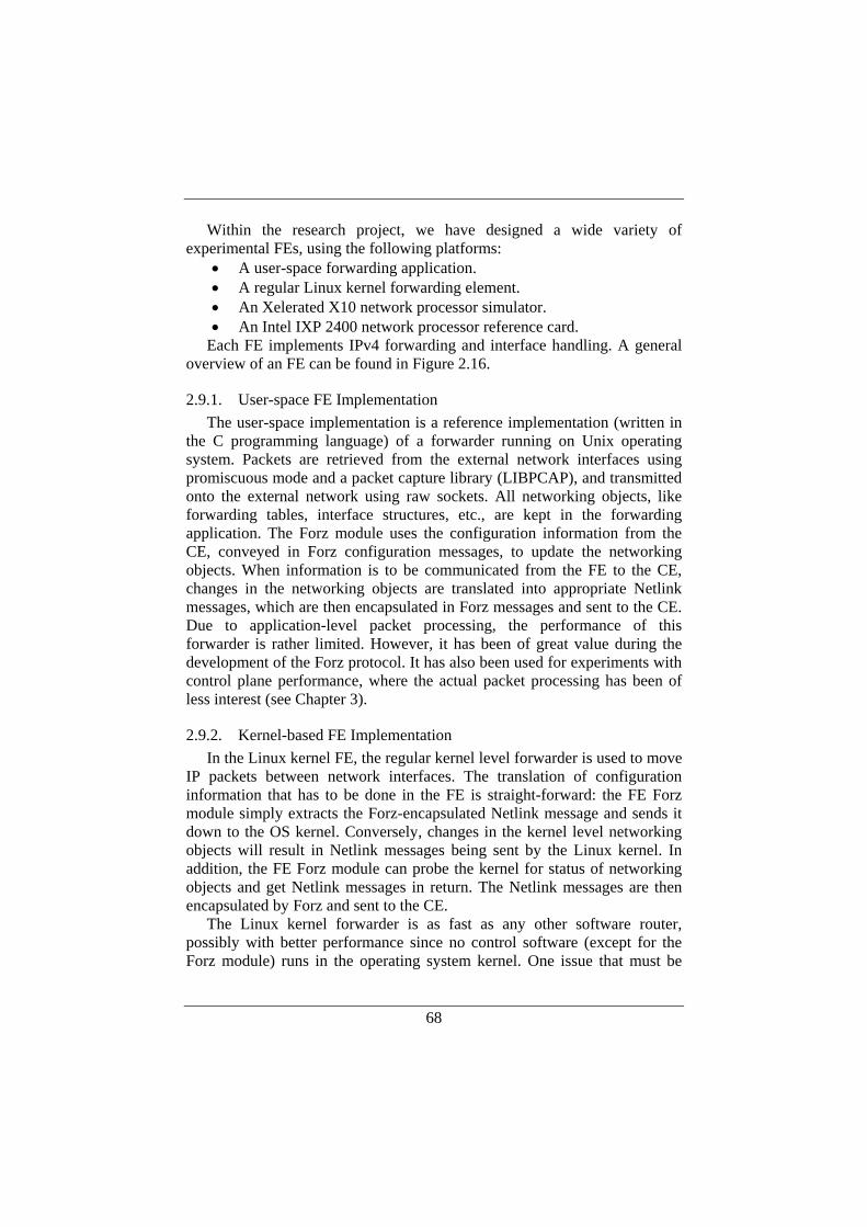
68
Within the research project, we have designed a wide variety of experimental FEs, using the following platforms:
• A user-space forwarding application. • A regular Linux kernel forwarding element. • An Xelerated X10 network processor simulator. • An Intel IXP 2400 network processor reference card.
Each FE implements IPv4 forwarding and interface handling. A general overview of an FE can be found in Figure 2.16.
2.9.1. User-space FE Implementation The user-space implementation is a reference implementation (written in
the C programming language) of a forwarder running on Unix operating system. Packets are retrieved from the external network interfaces using promiscuous mode and a packet capture library (LIBPCAP), and transmitted onto the external network using raw sockets. All networking objects, like forwarding tables, interface structures, etc., are kept in the forwarding application. The Forz module uses the configuration information from the CE, conveyed in Forz configuration messages, to update the networking objects. When information is to be communicated from the FE to the CE, changes in the networking objects are translated into appropriate Netlink messages, which are then encapsulated in Forz messages and sent to the CE. Due to application-level packet processing, the performance of this forwarder is rather limited. However, it has been of great value during the development of the Forz protocol. It has also been used for experiments with control plane performance, where the actual packet processing has been of less interest (see Chapter 3).
2.9.2. Kernel-based FE Implementation In the Linux kernel FE, the regular kernel level forwarder is used to move
IP packets between network interfaces. The translation of configuration information that has to be done in the FE is straight-forward: the FE Forz module simply extracts the Forz-encapsulated Netlink message and sends it down to the OS kernel. Conversely, changes in the kernel level networking objects will result in Netlink messages being sent by the Linux kernel. In addition, the FE Forz module can probe the kernel for status of networking objects and get Netlink messages in return. The Netlink messages are then encapsulated by Forz and sent to the CE.
The Linux kernel forwarder is as fast as any other software router, possibly with better performance since no control software (except for the Forz module) runs in the operating system kernel. One issue that must be
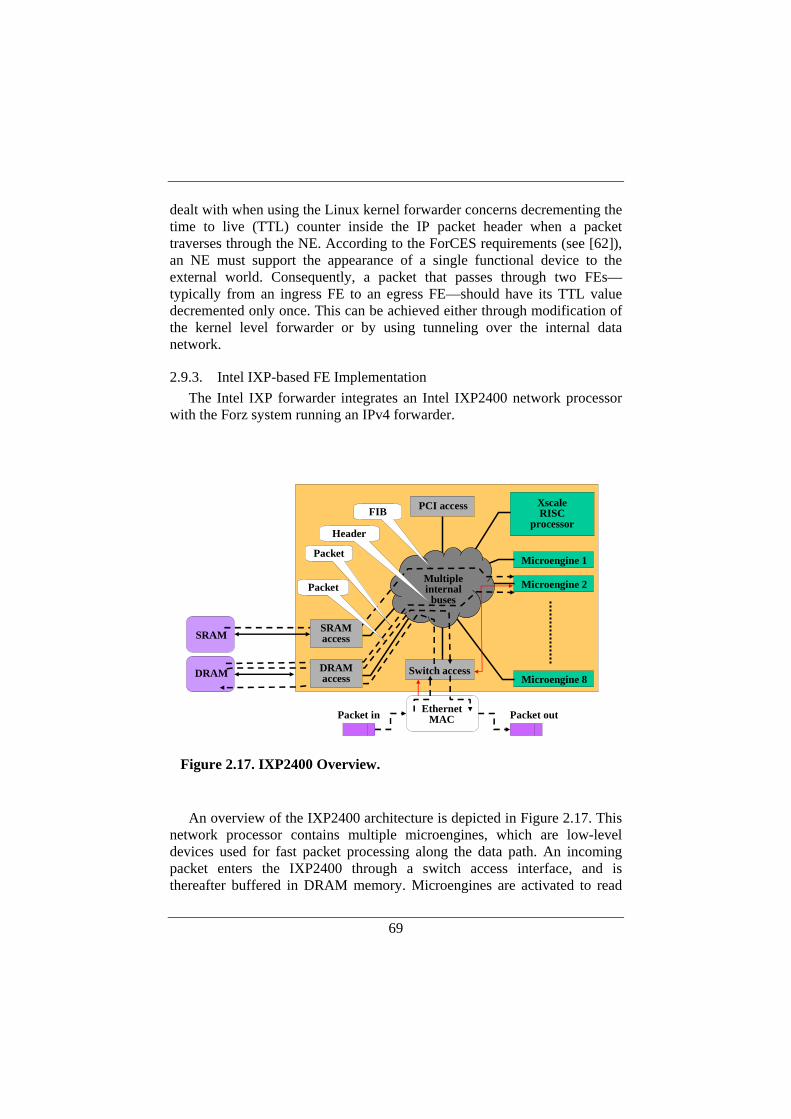
69
dealt with when using the Linux kernel forwarder concerns decrementing the time to live (TTL) counter inside the IP packet header when a packet traverses through the NE. According to the ForCES requirements (see [62]), an NE must support the appearance of a single functional device to the external world. Consequently, a packet that passes through two FEs—typically from an ingress FE to an egress FE—should have its TTL value decremented only once. This can be achieved either through modification of the kernel level forwarder or by using tunneling over the internal data network.
2.9.3. Intel IXP-based FE Implementation The Intel IXP forwarder integrates an Intel IXP2400 network processor
with the Forz system running an IPv4 forwarder.
An overview of the IXP2400 architecture is depicted in Figure 2.17. This
network processor contains multiple microengines, which are low-level devices used for fast packet processing along the data path. An incoming packet enters the IXP2400 through a switch access interface, and is thereafter buffered in DRAM memory. Microengines are activated to read
Microengine 1
Microengine 2
Microengine 8
XscaleRISC
processor
PCI access
Switch access
Multipleinternal
buses
Packet in Packet outEthernetMAC
SRAM
DRAM
FIB
SRAMaccess
Header
DRAMaccess
Packet
Packet
Figure 2.17. IXP2400 Overview.
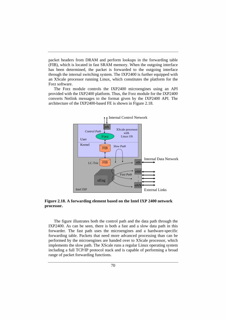
70
packet headers from DRAM and perform lookups in the forwarding table (FIB), which is located in fast SRAM memory. When the outgoing interface has been determined, the packet is forwarded to the outgoing interface through the internal switching system. The IXP2400 is further equipped with an XScale processor running Linux, which constitutes the platform for the Forz software.
The Forz module controls the IXP2400 microengines using an API provided with the IXP2400 platform. Thus, the Forz module for the IXP2400 converts Netlink messages to the format given by the IXP2400 API. The architecture of the IXP2400-based FE is shown in Figure 2.18.
The figure illustrates both the control path and the data path through the
IXP2400. As can be seen, there is both a fast and a slow data path in this forwarder. The fast path uses the microengines and a hardware-specific forwarding table. Packets that need more advanced processing than can be performed by the microengines are handed over to XScale processor, which implements the slow path. The XScale runs a regular Linux operating system including a full TCP/IP protocol stack and is capable of performing a broad range of packet forwarding functions.
Intel IXP
XScale processorwith
Linux OS
Internal Control Network
External Links
Internal Data Network
FIBKernelUser
FIBLC-Trie
uEngX10uEng
eth
ethN
::
uEngX10uEngFast Path
Slow Path
Control Path
eth0
Forz
eth
Figure 2.18. A forwarding element based on the Intel IXP 2400 network processor.
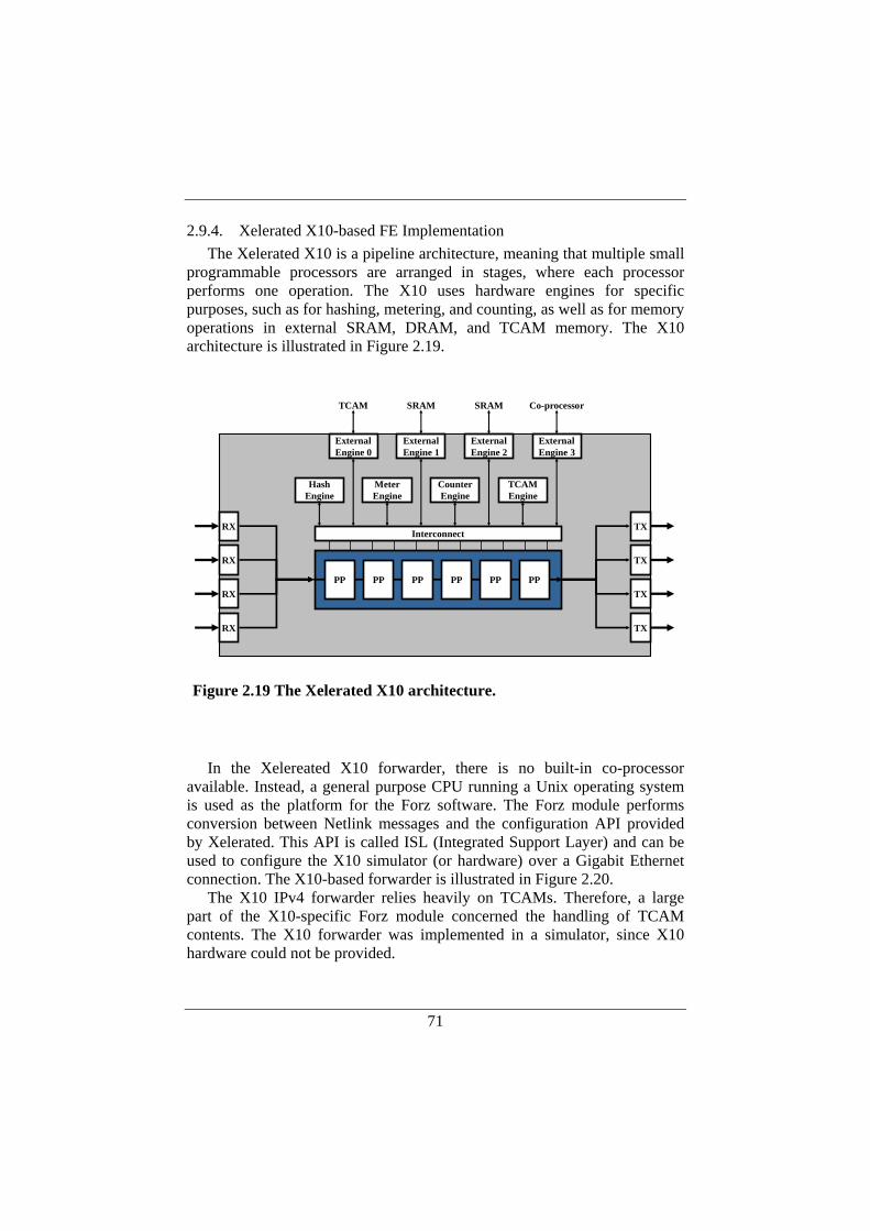
71
2.9.4. Xelerated X10-based FE Implementation The Xelerated X10 is a pipeline architecture, meaning that multiple small
programmable processors are arranged in stages, where each processor performs one operation. The X10 uses hardware engines for specific purposes, such as for hashing, metering, and counting, as well as for memory operations in external SRAM, DRAM, and TCAM memory. The X10 architecture is illustrated in Figure 2.19.
In the Xelereated X10 forwarder, there is no built-in co-processor
available. Instead, a general purpose CPU running a Unix operating system is used as the platform for the Forz software. The Forz module performs conversion between Netlink messages and the configuration API provided by Xelerated. This API is called ISL (Integrated Support Layer) and can be used to configure the X10 simulator (or hardware) over a Gigabit Ethernet connection. The X10-based forwarder is illustrated in Figure 2.20.
The X10 IPv4 forwarder relies heavily on TCAMs. Therefore, a large part of the X10-specific Forz module concerned the handling of TCAM contents. The X10 forwarder was implemented in a simulator, since X10 hardware could not be provided.
Interconnect
TCAM SRAM SRAM Co-processor
HashEngine
MeterEngine
CounterEngine
TCAMEngine
ExternalEngine 0
ExternalEngine 1
ExternalEngine 2
ExternalEngine 3
TX
TX
TX
TX
RX
RX
RX
RX
PP PP PP PP PP PP
Figure 2.19 The Xelerated X10 architecture.
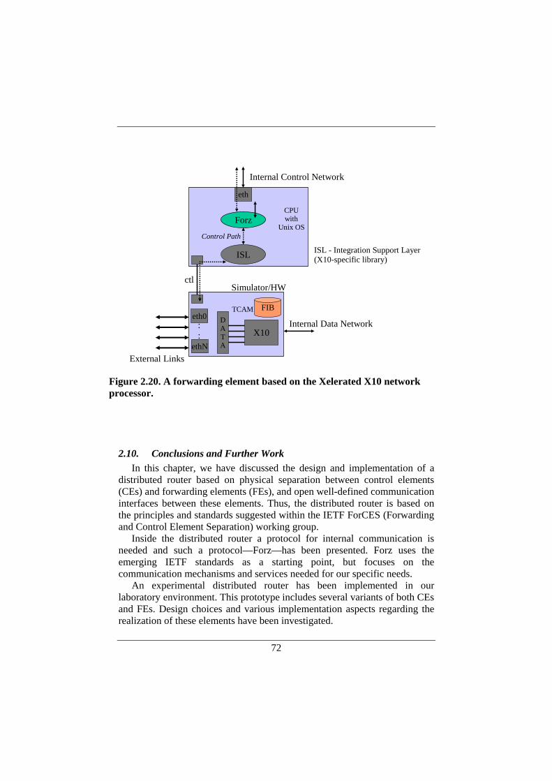
72
2.10. Conclusions and Further Work In this chapter, we have discussed the design and implementation of a
distributed router based on physical separation between control elements (CEs) and forwarding elements (FEs), and open well-defined communication interfaces between these elements. Thus, the distributed router is based on the principles and standards suggested within the IETF ForCES (Forwarding and Control Element Separation) working group.
Inside the distributed router a protocol for internal communication is needed and such a protocol—Forz—has been presented. Forz uses the emerging IETF standards as a starting point, but focuses on the communication mechanisms and services needed for our specific needs.
An experimental distributed router has been implemented in our laboratory environment. This prototype includes several variants of both CEs and FEs. Design choices and various implementation aspects regarding the realization of these elements have been investigated.
ISL
Internal Control Network
CPUwith
Unix OS
ctl
X10DATA
External Links
Simulator/HW
ISL - Integration Support Layer(X10-specific library)
FIBTCAMeth0
ethN
::
Internal Data Network
Forz
eth
Control Path
Figure 2.20. A forwarding element based on the Xelerated X10 network processor.
73
In particular we have studied CE implementations, where one important challenge is how network interfaces can be locally represented in the CE, when they in fact are remotely located at the FEs. This issue has been elucidated herein.
The main objective with the current implementation of support for multiple control elements is to demonstrate a proof of concept and to establish a platform for experimental work with multiple control elements. Such experiments are further discussed in Chapter 4. As a result, there are limitations with the experimental prototype. For instance there are no supervisory functions to decide any levels of authority between multiple CEs controlling the same FE. Conflicts may occur if two such CEs have different views on how an FE should be configured. There are no guarantees that all network objects in the FEs and the virtual representations in the CEs always will be synchronized. Inconsistencies may for example occur if one CE fails to update an instance of a network object for which a corresponding instance has been properly updated by another CE.

74

75
3. TRANSPORT MECHANISMS FOR INTERNAL CONTROL
The purpose of the internal network is to carry control and data traffic between the functional elements constituting a distributed router. As mentioned earlier, we have chosen to divide the internal network into two separate parts—one for control and one for data. One of the main challenges with a decentralized design relates to its distributed nature. There is a certain cost associated with the distributed structure since the internal communication results in overhead compared to a centralized design. A goal with the modular decentralized architecture is to use open well-defined communication interfaces between modules to enable heterogeneous designs, where modules from different vendors can interoperate. It is reasonable to assume that this design choice incurs overhead compared to proprietary distributed design, where it should be possible to achieve higher degree of optimization. One of the purposes with this work is to investigate the cost of having a more general communication interface between the modules of a decentralized router. It is our belief that the advantages with a distributed design outweigh the additional cost for the incurred communication overhead.
To our knowledge, the performance of control mechanisms for distributed routers has not gained much attention previously. An early version of such a mechanism (called Netlink2) was evaluated for a small-scale distributed system [36]. A different approach to speed up the internal communication is to use algorithmic methods to reduce the amount of forwarding information that needs to be distributed [63].
The purpose with this chapter is to investigate transport mechanisms for internal control information, and we focus on the CE-FE interface. There are different types of internal communication in a distributed router, with different service requirements. Some information may require reliable transport (e.g., route updates) while others may prefer timeliness rather than reliability (e.g., heartbeat messages). Further, the distribution of forwarding information requires efficient and reliable transfer of potentially relatively large amounts of data, while simple port configuration operations probably are best performed using request-response transactions. Therefore the Forz protocol is designed to use a variety of transport level mechanisms.
In particular, we study the communication overhead associated with distributing large forwarding tables from a control element, responsible for routing, to many forwarding elements, responsible for the actual forwarding of packet. Current forwarding tables can have relatively large memory

76
footprints, and the distribution of forwarding information to a large number of elements could potentially occupy the internal network for long periods of time. Such communication takes place when routing is started or restarted, but also during normal operation when there are sudden changes in the routing topology (due to route flaps, for instance).
The communication pattern for distribution of forwarding tables according to the above means that the same information is distributed to multiple receivers, which suggests that multicast communication could be appropriate. However, regular multicast based on UDP and IP multicast may not be suitable, due to its unreliable nature. If forwarding information is lost during the transport between control and forwarding elements, the distributed router will not perform the packet forwarding correctly. Clearly, this is not acceptable for a router. An interesting candidate for the internal communication may instead be reliable multicast. The purpose of this chapter is to investigate how reliable multicast can be used for internal communication in distributed routers.
This chapter is organized as follows. Section 3.1 gives an overview of protocols for reliable multicast transport. In Section 3.2, a classification and analysis of reliable multicast protocols is made to find a suitable protocol for our application. Thereafter, basic performance measurements are reported in Section 3.3 with the main purpose to find an ideal reference case. In Section 3.4 we continue with a performance evaluation of two reliable multicast protocol implementations that have been integrated into our experimental platform. In Section 3.5 we evaluate the total control plane performance when it comes to extensive dissemination of routing tables within the distributed router. A discussion around the results from our measurements is presented in Section 3.6. Finally, conclusions are drawn in Section 3.7.
3.1. Reliable Multicast Reliable multicast over IP networks has been an extensive research area
since the late 1980s, intensifying during the 1990s. Research on reliable multicast transport is still active, for example within IETF [96], even though the design proposal (or rather solution) space has been shrinking since the previous decade.
An overall problem with reliable multicast is that the requirements of multicast applications vary significantly. The situation for multicast transfers is very different from the reliable unicast case, where TCP can be used by virtually any application with requirements on reliable and ordered delivery of data. TCP has been efficiently tuned over the years and can adapt to many different network conditions in a point-to-point communication scenario. However, the mechanisms for reliability and congestion control in TCP
77
cannot easily be adapted to one-to-many or many-to-many communication scenarios. There are several explanations to the difficulties related to reliable multicast transmission. In addition to diverse application requirements when it comes to parameters like bandwidth requirements, delay requirements, and degree of reliability, a multicast scenario is not straightforward to define. There may be one or many senders within the multicast group, and members may dynamically tune in and disappear during the multicast session. Members will also have different conditions for sending and receiving data due to the heterogeneous nature of the Internet. Finally, there is no upper limit on the number of receivers, and therefore a reliable multicast protocol may have to scale to millions of receivers.
Accordingly, a large variety of multicast protocols have been proposed over the years, and several surveys illustrating the contemporary rich flora of protocols with various purposes can be found in the literature [68], [92]. Due to the large amount of protocols, different types of classification have been proposed. One example of a taxonomy is to classify the multicast transport protocols (both reliable and unreliable protocols) based on their features like data propagation, reliability mechanism, feedback control, congestion control, ordering, etc. [92]. Another taxonomy is focused on the interaction between data buffering at the sender, error control, and congestion control [68].
Regardless of the actual taxonomy, multicast transport protocols can be divided into the following groups [92]: general-purpose protocols, protocols with support for multipoint interactive applications, and protocols with support for data dissemination services. The main difference between the two latter categories relates to the applications’ requirements for delay and reliability. Interactive services favor bounded delay and delay variations before a high degree of reliability. Data dissemination applications, on the other hand, are likely to tolerate a longer delays and greater delay variations. However, they have strong requirements on reliable delivery. In the following, a historical overview of reliable multicast protocols belonging to the three groups is given.
The general-purpose category represents earlier protocols that were designed without a specific service or application in mind. Examples of such protocols are MTP (Multicast Transport Protocol) [5], RMP (Reliable Multicast Protocol) [108], and XTP (Xpress Transport Protocol) [99]. MTP and RMP are both layered on top of the unreliable IP multicast service. MTP uses a centralized control to guarantee ordered and reliable delivery to the receivers. It also uses an implicit mechanism for congestion control. RMP evolved from the same starting point as MTP, and also provides an ordered reliable delivery of data. RMP uses more advanced mechanisms for flow and

78
congestion control, namely the same mechanisms that are used in TCP. XTP provides services with full reliability in a TCP-like fashion as well as best-effort services like the service provided by UDP. Further, the flow control offered by XTP can be either window-based or rate-based.
Examples of multicast protocols with support for multipoint interactive applications are SRM [30] (Scalable Reliable Multicast), LBRM (Log-Based Receiver-Reliable Multicast) [50], and RAMP (Reliable Adaptive Multicast Protocol) [65]. SRM was originally developed for a distributed whiteboard application and is built on top of the best-effort IP multicast model. One important goal with SRM is to support a large number of receivers, a wide range of group sizes, and very large networks. SRM further takes a somewhat relaxed approach to reliability in the sense that all data will eventually be delivered to all group members, but no particular ordering is enforced. LBRM uses a logging server to keep track of all packets sent by the source and to perform retransmissions when necessary. Several logging servers can be used and organized in a hierarchical fashion where secondary logging servers can take care of local recovery for local receivers. RAMP is designed for a reliable communication medium (like a circuit-switched network) and maintains information about all receivers, which gives limited scaling properties compared to protocols based on the IP multicast model.
In the category of protocols with support for data dissemination services, MDP [73] (Multicast Dissemination Protocol), RMTP (Reliable Multicast Transport Protocol) [70], and MFTP (Multicast File Transfer Protocol) [82] can be found. MDP has been developed primarily for file distribution. A file is divided into data units that are distributed to a group of receivers using UDP and IP multicast. The sender controls the transmission rate and the recovery mechanism is based on both probing by the sender and repair requests from the receivers. RMTP supports reliable delivery of bulk data from one sender to many receivers. RMTP uses window-based flow control and allows receivers to dynamically join and leave a session. The protocol further guarantees that all receivers receive all of the data regardless of when they joined the session. MFTP is another protocol for distributing files from one sender to multiple receivers. MFTP can use unicast, multicast, or broadcast depending on the situation. Thus, MFTP does not require IP multicast to be activated to work. MFTP includes both a group management protocol of its own and a data transmission protocol where the sender announces a file transfer session and receivers register to receive the file.
3.2. Analysis of Reliable Multicast Protocols The categorization used in the previous section serves well as an
orientation in reliable multicast transport. However, when it comes to
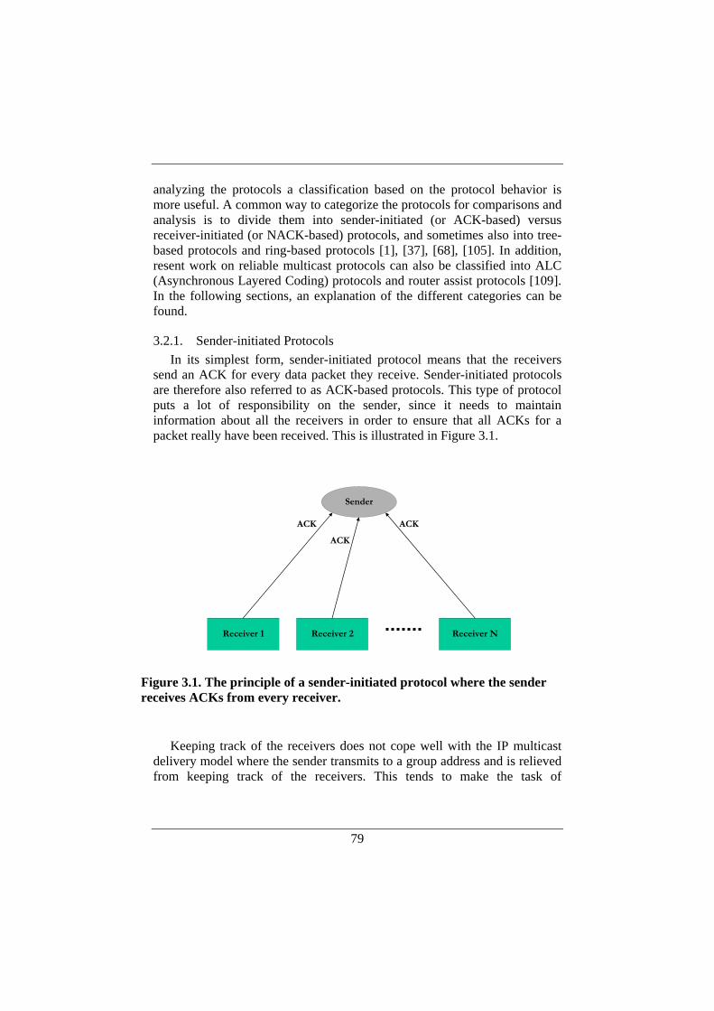
79
analyzing the protocols a classification based on the protocol behavior is more useful. A common way to categorize the protocols for comparisons and analysis is to divide them into sender-initiated (or ACK-based) versus receiver-initiated (or NACK-based) protocols, and sometimes also into tree-based protocols and ring-based protocols [1], [37], [68], [105]. In addition, resent work on reliable multicast protocols can also be classified into ALC (Asynchronous Layered Coding) protocols and router assist protocols [109]. In the following sections, an explanation of the different categories can be found.
3.2.1. Sender-initiated Protocols In its simplest form, sender-initiated protocol means that the receivers
send an ACK for every data packet they receive. Sender-initiated protocols are therefore also referred to as ACK-based protocols. This type of protocol puts a lot of responsibility on the sender, since it needs to maintain information about all the receivers in order to ensure that all ACKs for a packet really have been received. This is illustrated in Figure 3.1.
Keeping track of the receivers does not cope well with the IP multicast
delivery model where the sender transmits to a group address and is relieved from keeping track of the receivers. This tends to make the task of
Sender
Receiver 1 Receiver 2 Receiver N
ACK
ACK
ACK
Figure 3.1. The principle of a sender-initiated protocol where the sender receives ACKs from every receiver.
80
maintaining state information about receivers a complicated issue. In fact, it may be hard even to just determine the receiver set when using IP multicast.
In addition, sender-initiated protocols suffer from the well-known ACK implosion problem, meaning that the sender may have to process a large number of ACK messages from the receivers. As can be deduced from the figure above, the ACK implosion problem imposes limited scaling properties and the scheme is practical only for small receiver groups.
One advantage with an ACK-based protocol is that the sender is informed when all receivers have received a packet and can thus release the corresponding memory from the sending buffer [68].
Several of the early protocols for reliable multicast were sender-initiated, and one example of such a protocol is the previously mentioned XTP.
3.2.2. Receiver-initiated Protocols A receiver-initiated protocol uses NACKs (Negative ACKs) instead of
ACKs. This means that instead of sending ACKs for correctly received packets, receivers send a NACK when they discover that a packet is missing. Accordingly, the burden on the sender is reduced since it must no longer keep state information of all receivers. Instead, the receivers are responsible for the reliability.
A pure NACK-based protocol is also subject to message implosion since multiple NACKs for a specific lost packet could potentially reach the sender. In contrast to ACK-based protocols, it is enough if one NACK for a particular packet reaches the sender to trigger a retransmission. It is thus possible to apply a NACK suppression scheme to avoid NACK implosions at the sender. An example of NACK suppression is to multicast NACKs and to use random timers before sending a NACK. The timer avoids multiple NACKs to be sent simultaneously and also gives a chance that a receiver sees a NACK that has already been sent for a specific packet and can thus suppress its own corresponding NACK. Such a scheme is used in SRM [30], which is an example of a receiver-initiated protocol for reliable multicast.
Relieving the sender from the burden of processing ACKs together with the use of a NACK suppression scheme has proven to provide for good scaling properties and, as a consequence, several receiver-initiated protocols have been advocated [1], [30], [105].
A problem with pure receiver-initiated protocol where no ACKs are used is that it may be impossible for the sender to determine when buffer memory can be released since the sender can never be sure when a packet really has reached all the receivers [68]. Therefore, NACK-based protocols must sometimes be augmented with session-level support for determining when transmitted data can be released on the sender side [37]. For instance, ACKs
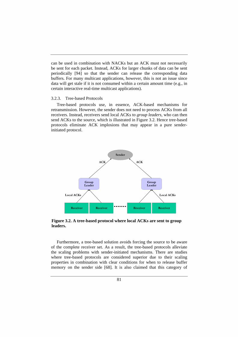
81
can be used in combination with NACKs but an ACK must not necessarily be sent for each packet. Instead, ACKs for larger chunks of data can be sent periodically [94] so that the sender can release the corresponding data buffers. For many multicast applications, however, this is not an issue since data will get stale if it is not consumed within a certain amount time (e.g., in certain interactive real-time multicast applications).
3.2.3. Tree-based Protocols Tree-based protocols use, in essence, ACK-based mechanisms for
retransmission. However, the sender does not need to process ACKs from all receivers. Instead, receivers send local ACKs to group leaders, who can then send ACKs to the source, which is illustrated in Figure 3.2. Hence tree-based protocols eliminate ACK implosions that may appear in a pure sender-initiated protocol.
Furthermore, a tree-based solution avoids forcing the source to be aware
of the complete receiver set. As a result, the tree-based protocols alleviate the scaling problems with sender-initiated mechanisms. There are studies where tree-based protocols are considered superior due to their scaling properties in combination with clear conditions for when to release buffer memory on the sender side [68]. It is also claimed that this category of
Sender
Receiver Receiver Receiver
ACKACK
Local ACKs
Receiver
GroupLeader
GroupLeader
Local ACKs
Figure 3.2. A tree-based protocol where local ACKs are sent to group leaders.
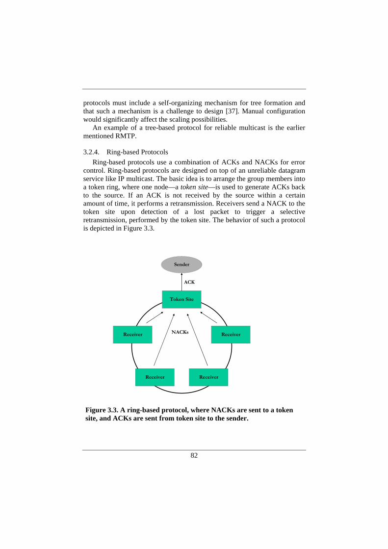
82
protocols must include a self-organizing mechanism for tree formation and that such a mechanism is a challenge to design [37]. Manual configuration would significantly affect the scaling possibilities.
An example of a tree-based protocol for reliable multicast is the earlier mentioned RMTP.
3.2.4. Ring-based Protocols Ring-based protocols use a combination of ACKs and NACKs for error
control. Ring-based protocols are designed on top of an unreliable datagram service like IP multicast. The basic idea is to arrange the group members into a token ring, where one node—a token site—is used to generate ACKs back to the source. If an ACK is not received by the source within a certain amount of time, it performs a retransmission. Receivers send a NACK to the token site upon detection of a lost packet to trigger a selective retransmission, performed by the token site. The behavior of such a protocol is depicted in Figure 3.3.
Receiver
Receiver
Receiver
ACK
Receiver
NACKs
Sender
Token Site
Figure 3.3. A ring-based protocol, where NACKs are sent to a token site, and ACKs are sent from token site to the sender.
83
The role of being token site is shifted between the receivers in a round-robin fashion, where the token is passed around between the group members. The token can be passed to the next receiver, i.e. the new token site, when the new token site has correctly received all packets the former site has received.
One of the main original purposes with ring-based protocol was to provide atomic and total ordering of transmissions. RMP is an example of a ring-based reliable multicast protocol, which can provide total ordering and atomicity guarantees.
3.2.5. Asynchronous Layered Coding (ALC) The primary goal with ALC protocol family is to provide massive
scalability, meaning that bulk-data can be delivered from one sender to basically an unlimited number of heterogeneous receivers. ALC protocols are built on top of the traditional best-effort unreliable IP multicast service, where they provide session management, congestion control, and reliability.
In contrast to the previously mentioned categories of reliable multicast protocols, ALC requires no feedback from the receivers to the sender. This is possible through the use of FEC—Forward Error Correction—meaning that error-correcting codes are used to detect and correct errors within a packet. Using FEC for reliable multicast protocols has been suggested and analyzed by several researchers over the years [33], [89], [90]. The basic principle behind FEC is that the source sends redundant packets along with a sequence of original packets so that receivers can use the redundant information to reconstruct data in case of packet losses between sender and receivers. In general, FEC can significantly reduce the number of retransmissions needed. Despite the overhead introduced by redundant packets, FEC may result in improved efficiency, especially for very large multicast groups. If there are millions of receivers, the chance for a packet to reach all receivers is extremely low even for modest loss rates. Therefore, each packet will probably have to be retransmitted at least once anyway. FEC is more efficient than retransmission in this case since one single FEC repair packet can be enough to reconstruct data at multiple receivers even though these receivers may have lost different original packets. For the same reason, FEC provides a more efficient NACK suppression—a NACK for one lost packet from one receiver can suppress the NACK for another packet lost by another receiver.
The ALC protocols have eliminated the need for feedback from receivers to the sender, which obviously scales excellently with the number of receivers [72]. An example of an ALC protocol with an FEC approach that does not require any feedback from the receivers is the digital fountain [13].

84
In a digital fountain, the sender inserts a stream of encoding packets constructed from the original data into the network, addressed to a multicast group. Receivers can join the multicast group at any time and reconstruct the data from any subset of these encoding packets as long as the length of this subset is the same as the length of the original data.
ALC protocols use layered multicast [77] for congestion control. The layered multicast approach means that the sender transmits data to several multicast groups. Data is encoded in layers that are sent on multiple multicast groups, and the transmission rate is increased with the number of layers, i.e., the number of multicast groups. A receiver can then join one or several of these multicast groups depending on the data rate the receiver can accept. Thereby, the responsibility of rate adaptation is transferred from the sender to the receivers.
3.2.6. Router Assist Yet another reliable multicast protocol family can be recognized that
make use of advanced router functionality for efficient operation. Such protocols can be constructed from basically any of the previously mentioned categories and are sometimes referred to as router assist protocols [109]. Router assist protocols are normally designed so that they can still operate in an environment without any support from the routers since the opposite would significantly limit the practical possibilities to deploy the protocol in the Internet. However, assistance from the routers can be utilized to increase the efficiency of the protocol.
A modern protocol that fits into this class is PGM—Pragmatic General Multicast [33]. PGM is designed for applications that can accept a certain level of packet loss, or deal with this limited loss at the application level. Applications for which fresh data is more important than recovered old data, which might be considered stale, can benefit from using PGM. Stock quote dissemination is one such example. PGM uses NACKs with random-based back-off timers for NACK suppression together with FEC and NACK elimination. A PGM tree is built up using PGM-enabled network elements (typically routers with PGM support) along the IP multicast delivery tree. Receivers send unicast NACKs to their PGM parent router upon detection of lost packets. The PGM parent router forwards the unicast NACK up the tree towards the source, and also sends a multicast NACK confirmation to its children. This way, a receiver can detect when another receiver has sent a NACK and also suppress its own NACK, if necessary.
PGM does not perform congestion control. Instead, the sender is rate-limited. PGM can provide feedback about the network state to the
85
application, but the actual congestion control is left to the application programmer.
One of the main purposes of PGM is extreme scalability, which can be achieved with router support for PGM. Without router support, PGM uses NAK suppression and FEC to provide somewhat limited scaling.
3.2.7. Current Status Today, it is generally agreed that reliable multicast communication
cannot rely on one single generic transport protocol that sufficiently and efficiently fulfills the requirements from a wide variety of target applications. Instead, the efficiency of the protocol depends on how well the application matches the protocol design [37], [59]. Some of the most recent work on protocols for reliable multicast can be found within the RMT (Reliable Multicast Transport) IETF working group [96].
In the work with standardization of reliable multicast protocols, the IETF has taken a modular approach by developing “building blocks” of protocol mechanisms, and then standardize protocols as instantiations of combinations of building blocks.
The standardization mainly concerns bulk data reliable multicast transport and is based on experiences from the extensive previous work on reliable multicast. By extracting protocol components that are common to several different reliable multicast protocols, various building blocks can be designed [109] and standardized by IETF. Examples of building blocks are NACK-based reliability, FEC (Forward Error Correction) coding, congestion control, and tree configuration. A building block normally has an application programming interface for interfacing to applications or other building blocks.
When it comes to actual protocol instantiation, the current focus is on two different protocols: NORM (NACK-Oriented Reliable Multicast) [2] and an ALC (Asynchronous Layered Coding) using FEC [72]. In addition, IETF has published a specification of PGM as an experimental protocol [102]. ALC was covered in Section 3.2.5, and PGM in Section 3.2.6. In the following, a closer description of NORM is given.
NORM [1], [2], [3] is one the most recent reliable multicast protocol instantiations currently being standardized within the IETF. NORM is based on the use of NACKs to send repair requests back to the sender when data is missing at the receiver side. To avoid NACK implosions where many receivers simultaneously send NACKs back to the sender, NORM includes mechanisms for suppressing redundant NACK transmissions among a group of receivers. NACK suppression in NORM is based on exponentially distributed random backoff timers, and NORM is measuring round trip
86
timing within the multicast group during the session in a dynamic fashion to determine appropriate timer values. NORM also provides optional use of positive acknowledgments (ACKs), which are generally used only for congestion control purposes. NORM supports rate-based control as well as congestion control. The former mode means that a transmission peak rate is set while the latter means that the transmission rate is automatically adjusted.
In addition to retransmissions, NORM includes support for forward error correction. NORM is mainly intended for “flat” multicast topologies (in contrast to hierarchical, tree-based topologies). Further, NORM is primarily thought for a scenario where one sender transmits to many receivers, but NORM may also operate with several senders.
NORM defines three different types of content objects: data, file and stream. File and data objects require that the size of the object is known in advance, while the stream-oriented service is designed for continuous data streams without pre-determined boundaries. In principle, there is no difference between file and data object. The differentiation between the two is only made to give receivers information about the type of storage that is suitable for the content.
3.2.8. Reliable Multicast for the Internal Network In our application of reliable multicast, the geographical size of the
multicast group is limited and the group is formed in a controlled environment (within the internal network of the distributed router). Even though it is possible to build a router-based internal network for the distributed router, the normal scenario is that high-performance switches are used and that there are no routers within the internal network.
When it comes to studying reliable multicast protocols for our application, we draw the following conclusions: a) ALC protocols have a strong focus on massive scalability and long-lived
sessions. This does not really match our application for two main reasons. First, even though the distributed router architecture should scale to thousands of forwarding elements, this group size is far from the million-range targeted by ALC protocols. Second, the dissemination of routing tables results in a rather limited session length compared to the long-lived sessions addressed by ALC protocols.
b) Router assist protocols are based on assistance from intermediate routers between sender and receivers for efficient operation. Even though router assist protocols, like PGM, may work without router support such a protocol would not be our first choice since there are no intermediate routers in the internal network in our scenario. The fact that we have a flat internal structure also leads us to exclude tree-based protocols.

87
c) Finally, pure sender-initiated protocols and ring-based protocols appear to be somewhat outdated. To our knowledge, no recent work has been made regarding these classes of reliable multicast protocols.
NORM, on the other hand, seems like an interesting candidate for our purposes. The switched-based internal network used in the distributed router constitutes an environment that seems to fit well with the model underlying the design of NORM. Accordingly, a study of NORM performance seems to be well motivated. Out of the three types of content objects supported by NORM, the use of stream objects appears most suitable for dynamically produced content, which is the general case when it comes to routing table updates.
Even though research on reliable multicast has been extensive, with numerous protocol suggestions, simulations, and analytical comparisons, experimental work on reliable multicast has been fairly limited [8], [110]. Other researchers have searched for different reliable multicast protocol implementations with reasonable maturity and support for various operating systems, for instance when it comes to studying reliable multicast for Grid applications [8]. It can be noted that there are not that many implementations to choose from. We have however found two implementations of the NORM protocol instantiation. These implementations have support for different types of transport services, and are evaluated in the following section. One implementation comes from INRIA (Institut National de Recherche en Informatique et en Automatique) [53], and the other from NRL (Naval Research Laboratory) [91]. We refer to the implementations as INRIA NORM and NRL NORM respectively. Both implementations support multiple platforms and have turned out to be possible to integrate with our middleware for distributed routers.
INRIA NORM is part of a larger project called MCL (MultiCast Library) and NRL NORM stems from an implementation of the earlier mentioned protocol MDP [73].
3.3. Basic Performance Measurements In a decentralized architecture, there is an extra cost due to internal
communication, compared to a centralized system. We believe that the choice of protocols and communication mechanisms has large influence on the efficiency of the internal transactions. The purpose of our performance evaluation is to investigate how different mechanisms affect the cost in terms of time spent on internal communication. We are interested in both the absolute values of the time it takes to distribute information over the internal network and in how the internal communication scales with the number of elements in the system.

88
3.3.1. Experimental Setup The experimental platform consists of one CE and up to 16 FEs. The CE
and FEs are based on rack-mounted PCs with 1.70 GHz Intel Pentium 4 processors, running the OpenBSD operating system. The internal network consists of three 100 Mb/s Ethernet switches (Netgear FSM726S) that interconnect the CE and the FEs. The switches are wire-speed Ethernet switches, and none of the output ports are overloaded in our measurements. Thus, there is no packet loss inside the internal network
The measurements focus on the actual communication between the CE
and the FEs. We do not include the time for updating the FIB in the FEs, since the FIB update time depends on the type of forwarding element and the design of the FIB. The FIB can be implemented in a variety of ways, such as binary trees or hash tables in software based FEs, and content addressable memory (CAM) in FEs based on specialized hardware. The time it takes to update the FIB may vary significantly between different designs. Therefore we chose to only consider the transaction times introduced by Forz and the internal network.
The performance measurements are run in the following way. First, the FEs and the CE are started. The CE then reads a configuration file holding 100,000 routing table entries and distributes the entries to the FEs, and we measure the time it takes to send out those entries. All measurements in this section have been repeated several times and the variations in the measurement points are negligible.
In the following we study not only NORM, but also TCP and UDP. Multiple TCP connections as well as UDP in combination with IP multicast are interesting to compare with NORM from several perspectives. First, measurements of using TCP and UDP as transport mechanisms for Forz may
FE 8CE FE 1 FE 9 FE 16
Switch
Switch Switch
Figure 3.4. Experimental setup for performance evaluation.
89
serve as a reference to study the gains of using multicast transmissions instead of multiple TCP connections. Also, TCP- and UDP-based ForCES transport mapping layers over IP networks are currently undergoing standardization within IETF. However, to our knowledge, no studies on the performance under heavy load of the suggested transport mechanisms for ForCES have been published.
3.3.2. Multiple TCP Connections Using multiple TCP connections is a straightforward way to accomplish a
reliable distribution service. A TCP connection is established to each FE, and the route updates are duplicated over the connections. This means that there will be several TCP transfers going on in parallel. However, since the link is saturated, there is no performance gain from this parallelism. Instead, the total distribution time increases linearly with the number of FEs, which can be seen in Figure 3.7.
3.3.3. Ideal UDP Multicast In contrast to TCP, UDP lacks mechanisms for flow control, congestion
control, and segmentation. So in order to use UDP, we have to add support for those mechanisms in Forz. For example, we quickly discovered that if we use UDP without any flow control, a large portion of the route updates are lost since the receivers (the FEs) cannot process the incoming messages fast enough. Furthermore, we also found that the packet size has significant influence on UDP performance. However, congestion control is not needed in our measurements, since they are performed in a controlled environment without congestion.
To implement flow control at the Forz level, a simple ACK strategy is used. We introduce an ACK interval specifying the number of Forz messages a sender can send before waiting for an ACK. We also implement a form of segmentation for UDP by letting the sender accumulate several Forz messages and send those messages in one UDP datagram. This can be compared with the way TCP tries to send as large segments as possible. We experiment with different values of the ACK interval and the number of Forz messages per UDP datagram to find suitable values for our further experiments.
The purpose of the first measurement is to investigate how the ACK interval affects the total time to distribute the routing table (see Figure 3.5). This measurement is done with UDP multicast to 16 FEs, and 8 Forz messages accumulated in each UDP datagram.

90
The graph shows that a significant performance improvement can be made by increasing the ACK interval, but that the relative gain decreases with an increasing ACK interval. Further, there is an upper bound on the ACK interval: if the ACK interval is too large, packets will be lost. For example, in our experiment, we found that if more than 48 Forz messages are sent before waiting for an ACK, receiver buffers will overflow and packets will be lost. This ACK interval is specific to our configuration. A general solution would be to implement an adaptive flow control, e.g., such as sliding windows in TCP.
The next measurement investigates the UDP datagram size, in terms of number of Forz messages per UDP packet. The total distribution time as a function of UDP datagram size is shown in Figure 3.6. This measurement is performed with UDP multicast to 16 FEs, and the ACK interval is 48 Forz messages per ACK.
The figure shows that the total time is reduced with almost a factor of two by going from one to eight Forz messages per UDP datagram, but also that there is not much to be gained by increasing the UDP datagram size beyond that. There is a small irregularity between the second and the third measurement points. This behavior can be explained by the buffer management mechanisms in the operating system (OpenBSD), which has an optimization for small packets (less than 236 bytes). Accumulating three Forz messages per UDP datagram is just above the limit for this optimization to be applicable.
Figure 3.5. Time measurements for different ACK intervals when 1 Forz message per UDP datagram is sent. This example is made for multicast transfers to 16 FEs.

91
Based on the results of this initial investigation of ACK intervals and packet sizes, we chose to use an ACK interval of 48 Forz messages per ACK, and 8 Forz messages per UDP datagram, for the following experiment.
3.3.4. Performance Measurements of TCP and UDP In this section, we study how the routing table distribution time varies
with the number of FEs for the three different transport protocols: UDP unicast, UDP multicast, and TCP. We let the number of FEs vary from 1 to 16, and the results are shown in Figure 3.7.
For UDP, we employ a rudimentary flow control mechanism, where we let one of the FEs be responsible for sending ACKs back to the CE. This is a simplification, which works in our homogeneous environment where all FEs are identical. It would not be a generally applicable flow-control mechanism for UDP; we use it merely as a means to control UDP packet rate in our measurements.
We observe that with UDP unicast, it takes slightly more than 2 seconds to communicate the 100,000 route updates to one single FE. When the number of FEs increases, there is a linear increase in the time it takes to distribute the routing table to all FEs. One might expect that the time would increase with 2 seconds for each additional FE, but a certain level of parallelism is achieved due to the fact that a set of route updates are distributed to all FEs before the CE starts waiting for an ACK.
Figure 3.6. Time measurements for different UDP datagram sizes when the ACK interval is 48 messages per ACK. This example is made for multicast transfers to 16 FEs.

92
For UDP multicast, the time is constant independently of the number of
FEs, and the value is roughly the same as for UDP unicast with one FE (slightly more than 2 seconds). Thus, in this experimental setup, the system can distribute roughly 50,000 route updates per second when the Forz protocol uses UDP multicast as the transport mechanism.
For comparison, we also measure TCP. Thus, the transport is reliable and there is no need for Forz level ACKs and segmentation. The drawback is that multicast transfers cannot be used. The results show that the total time to distribute the routing table is slightly lower for TCP than for UDP unicast, which can be explained by TCP’s more efficient flow control mechanism and more optimal segmentation.
3.3.5. Ideal Case for UDP Multicast We experiment with different values of the ACK interval and the number
of Forz messages per UDP datagram to find suitable values for our further experiments. When it comes to segmentation, the general rule is that best efficiency is achieved with largest possible datagram size as long as it fits within the network’s maximum transmission unit (MTU). The maximum number of Forz messages that can be fit into the MTU of the internal control network is 16. Further there is an upper bound on the ACK interval: if the ACK interval is too large, packets will be lost. We also found that when the maximum number of Forz messages per datagram is used, the ACK interval
Figure 3.7. Time measurements for distributing 100,000 routing table entries to a number of FEs, using different transport mechanisms.
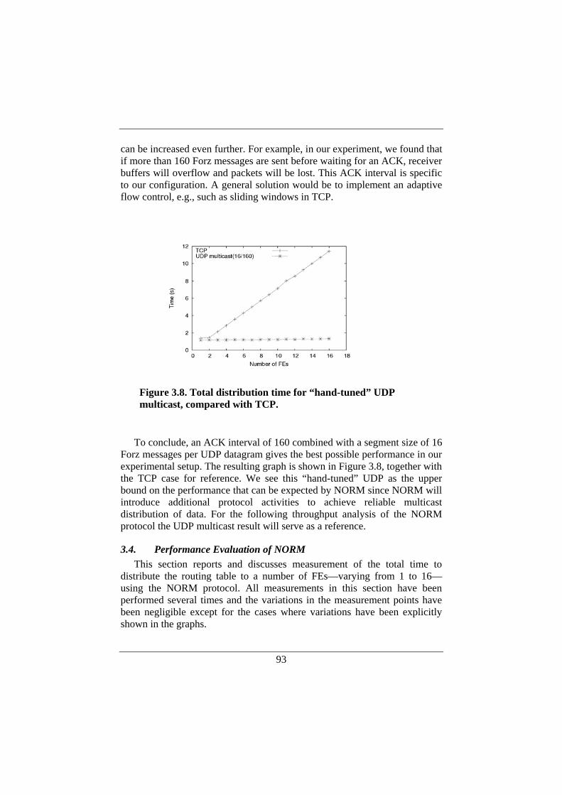
93
can be increased even further. For example, in our experiment, we found that if more than 160 Forz messages are sent before waiting for an ACK, receiver buffers will overflow and packets will be lost. This ACK interval is specific to our configuration. A general solution would be to implement an adaptive flow control, e.g., such as sliding windows in TCP.
To conclude, an ACK interval of 160 combined with a segment size of 16
Forz messages per UDP datagram gives the best possible performance in our experimental setup. The resulting graph is shown in Figure 3.8, together with the TCP case for reference. We see this “hand-tuned” UDP as the upper bound on the performance that can be expected by NORM since NORM will introduce additional protocol activities to achieve reliable multicast distribution of data. For the following throughput analysis of the NORM protocol the UDP multicast result will serve as a reference.
3.4. Performance Evaluation of NORM This section reports and discusses measurement of the total time to
distribute the routing table to a number of FEs—varying from 1 to 16—using the NORM protocol. All measurements in this section have been performed several times and the variations in the measurement points have been negligible except for the cases where variations have been explicitly shown in the graphs.
Figure 3.8. Total distribution time for “hand-tuned” UDP multicast, compared with TCP.
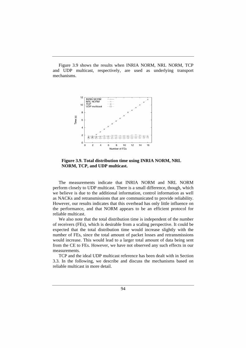
94
Figure 3.9 shows the results when INRIA NORM, NRL NORM, TCP and UDP multicast, respectively, are used as underlying transport mechanisms.
The measurements indicate that INRIA NORM and NRL NORM
perform closely to UDP multicast. There is a small difference, though, which we believe is due to the additional information, control information as well as NACKs and retransmissions that are communicated to provide reliability. However, our results indicates that this overhead has only little influence on the performance, and that NORM appears to be an efficient protocol for reliable multicast.
We also note that the total distribution time is independent of the number of receivers (FEs), which is desirable from a scaling perspective. It could be expected that the total distribution time would increase slightly with the number of FEs, since the total amount of packet losses and retransmissions would increase. This would lead to a larger total amount of data being sent from the CE to FEs. However, we have not observed any such effects in our measurements.
TCP and the ideal UDP multicast reference has been dealt with in Section 3.3. In the following, we describe and discuss the mechanisms based on reliable multicast in more detail.
Figure 3.9. Total distribution time using INRIA NORM, NRL NORM, TCP, and UDP multicast.
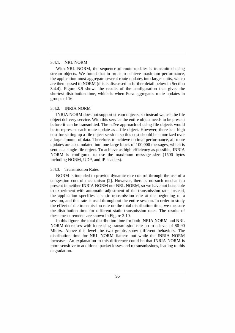
95
3.4.1. NRL NORM With NRL NORM, the sequence of route updates is transmitted using
stream objects. We found that in order to achieve maximum performance, the application must aggregate several route updates into larger units, which are then passed to NORM (this is discussed in further detail below in Section 3.4.4). Figure 3.9 shows the results of the configuration that gives the shortest distribution time, which is when Forz aggregates route updates in groups of 16.
3.4.2. INRIA NORM INRIA NORM does not support stream objects, so instead we use the file
object delivery service. With this service the entire object needs to be present before it can be transmitted. The naïve approach of using file objects would be to represent each route update as a file object. However, there is a high cost for setting up a file object session, so this cost should be amortized over a large amount of data. Therefore, to achieve optimal performance, all route updates are accumulated into one large block of 100,000 messages, which is sent as a single file object. To achieve as high efficiency as possible, INRIA NORM is configured to use the maximum message size (1500 bytes including NORM, UDP, and IP headers).
3.4.3. Transmission Rates NORM is intended to provide dynamic rate control through the use of a
congestion control mechanism [2]. However, there is no such mechanism present in neither INRIA NORM nor NRL NORM, so we have not been able to experiment with automatic adjustment of the transmission rate. Instead, the application specifies a static transmission rate at the beginning of a session, and this rate is used throughout the entire session. In order to study the effect of the transmission rate on the total distribution time, we measure the distribution time for different static transmission rates. The results of these measurements are shown in Figure 3.10.
In this figure, the total distribution time for both INRIA NORM and NRL NORM decreases with increasing transmission rate up to a level of 80-90 Mbit/s. Above this level the two graphs show different behaviors. The distribution time for NRL NORM flattens out while the INRIA NORM increases. An explanation to this difference could be that INRIA NORM is more sensitive to additional packet losses and retransmissions, leading to this degradation.

96
3.4.4. Aggregation With the support of stream objects in NRL NORM, the Forz application
can feed route updates to NORM in a continuous stream. As in many other protocols, the message size has large influence on the performance in NORM. It is better to send larger message, since it allows the per-message cost to be amortized over larger units of data. However, a route update in our system is much smaller than what fits in a NORM data message on an Ethernet (84 bytes versus 1344 bytes). So in order to reduce the distribution time, several route updates should be aggregated into larger NORM messages.
In NRL NORM, there is support for configurable aggregation where the application can specify a preferred message size. NRL NORM will then aggregate data from the application into messages of the preferred size. Alternatively, the application can perform aggregation, by passing several route updates as a single data unit to NORM.
Figure 3.11 shows the results of measuring the distribution time with different combinations of aggregation at the user-level and in NRL NORM. The target message size used in these measurements corresponds to the maximum Ethernet frame size. We get the shortest distribution time with application-level aggregation. Yet another possibility would be to use both NORM NRL aggregation and application-level aggregation. However, as long as the application level aggregates enough data to fill the maximum segment size, such a combination will not give any further improvements.
Figure 3.10. Total distribution time for different transmission rates, using INRIA NORM and NRL NORM respectively.
97
As might be expected, without any aggregation at all the distribution time
gets much longer (around 10 times longer compared to application-level aggregation). Aggregation in NRL NORM gives an improvement, compared to no aggregation, but is still considerably slower than application-level aggregation. In addition, for repeated measurements we observe large variations in the distribution time with NRL NORM aggregation (minimum and maximum values over 10 repetitions are shown in Figure 3.11, together with the mean value). We notice that in the cases of shorter distribution time, there are more retransmissions taking place. Based on this observation, we conjecture that the randomized NACK suppression timers and the packet loss patterns sometimes trigger more frequent retransmissions, which tend to shorten the total distribution time.
3.5. Overall Control Plane Performance The performance measurements presented in the previous sections
(Section 3.3 and 3.4) focused on the actual communication overhead introduced when physically separating CEs and FEs with an internal IP-based network. Therefore, we used only simple receivers that performed no application-level processing of the data, i.e., the routes that were distributed by the CE was never installed in the FEs.
Figure 3.11. Total distribution time using NRL NORM with different aggregation methods. All measurements were repeated 10 times, but only NORM aggregation resulted in noticeable variations.
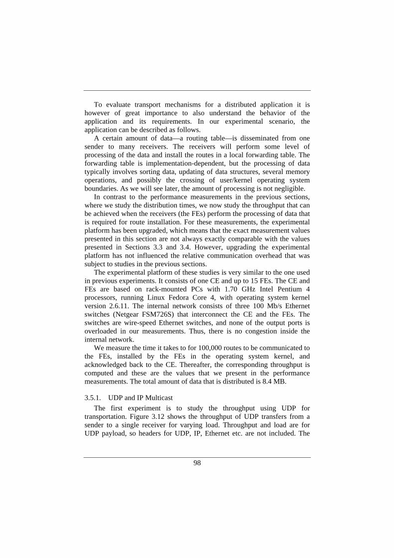
98
To evaluate transport mechanisms for a distributed application it is however of great importance to also understand the behavior of the application and its requirements. In our experimental scenario, the application can be described as follows.
A certain amount of data—a routing table—is disseminated from one sender to many receivers. The receivers will perform some level of processing of the data and install the routes in a local forwarding table. The forwarding table is implementation-dependent, but the processing of data typically involves sorting data, updating of data structures, several memory operations, and possibly the crossing of user/kernel operating system boundaries. As we will see later, the amount of processing is not negligible.
In contrast to the performance measurements in the previous sections, where we study the distribution times, we now study the throughput that can be achieved when the receivers (the FEs) perform the processing of data that is required for route installation. For these measurements, the experimental platform has been upgraded, which means that the exact measurement values presented in this section are not always exactly comparable with the values presented in Sections 3.3 and 3.4. However, upgrading the experimental platform has not influenced the relative communication overhead that was subject to studies in the previous sections.
The experimental platform of these studies is very similar to the one used in previous experiments. It consists of one CE and up to 15 FEs. The CE and FEs are based on rack-mounted PCs with 1.70 GHz Intel Pentium 4 processors, running Linux Fedora Core 4, with operating system kernel version 2.6.11. The internal network consists of three 100 Mb/s Ethernet switches (Netgear FSM726S) that interconnect the CE and the FEs. The switches are wire-speed Ethernet switches, and none of the output ports is overloaded in our measurements. Thus, there is no congestion inside the internal network.
We measure the time it takes to for 100,000 routes to be communicated to the FEs, installed by the FEs in the operating system kernel, and acknowledged back to the CE. Thereafter, the corresponding throughput is computed and these are the values that we present in the performance measurements. The total amount of data that is distributed is 8.4 MB.
3.5.1. UDP and IP Multicast The first experiment is to study the throughput using UDP for
transportation. Figure 3.12 shows the throughput of UDP transfers from a sender to a single receiver for varying load. Throughput and load are for UDP payload, so headers for UDP, IP, Ethernet etc. are not included. The
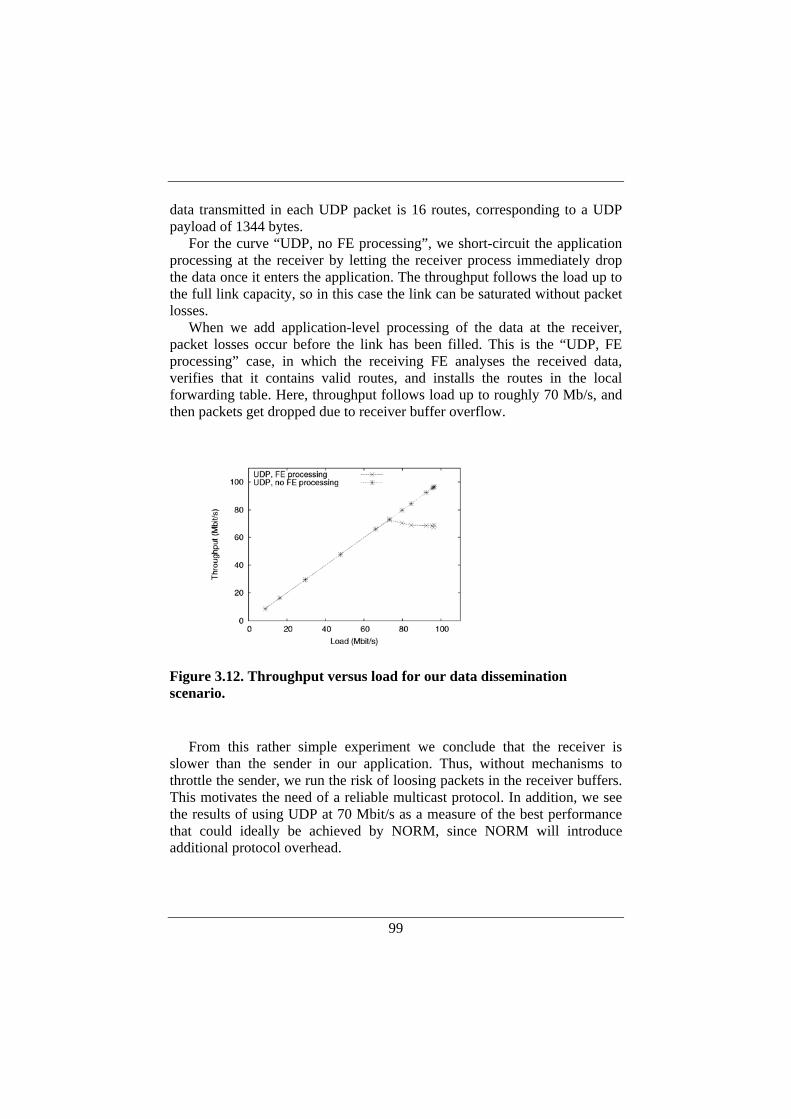
99
data transmitted in each UDP packet is 16 routes, corresponding to a UDP payload of 1344 bytes.
For the curve “UDP, no FE processing”, we short-circuit the application processing at the receiver by letting the receiver process immediately drop the data once it enters the application. The throughput follows the load up to the full link capacity, so in this case the link can be saturated without packet losses.
When we add application-level processing of the data at the receiver, packet losses occur before the link has been filled. This is the “UDP, FE processing” case, in which the receiving FE analyses the received data, verifies that it contains valid routes, and installs the routes in the local forwarding table. Here, throughput follows load up to roughly 70 Mb/s, and then packets get dropped due to receiver buffer overflow.
From this rather simple experiment we conclude that the receiver is
slower than the sender in our application. Thus, without mechanisms to throttle the sender, we run the risk of loosing packets in the receiver buffers. This motivates the need of a reliable multicast protocol. In addition, we see the results of using UDP at 70 Mbit/s as a measure of the best performance that could ideally be achieved by NORM, since NORM will introduce additional protocol overhead.
Figure 3.12. Throughput versus load for our data dissemination scenario.
100
3.5.2. Multiple TCP Connections It could be argued that multiple TCP connections and Gigabit Ethernet
would be an appealing alternative for our scenario. We have measured the sender’s maximum transmission capacity, which resulted in slightly below 200 Mbit/s. Assuming that the capacity of the receiver is the same for TCP as for UDP above, our distributed application have a transmission capacity of 200 Mbit/s, and a maximum receiving capacity of 70 Mbit/s. Furthermore, there is no congestion in the network so the throughput is determined solely by the receivers in our case. Hence, our scenario is as follows: With up to three receivers, multiple TCP connections would be able to serve the receivers at near full speed. Thereafter, the sender is saturated and the receiver rate will drop to 200/n, where n is the number of receivers. Increasing the number of connections will thus simply decrease the speed of each connection. Furthermore, earlier performance measurements of using multiple TCP connections, presented in Section 3.3.2, showed a linear increase in distribution time (see Figure 3.7). The linear increase in distribution time shown in the figure indicates that the scaling properties of using TCP in our scenario are rather limited. Considering that a distributed router architecture should be scaleable to hundreds of FEs, [62], using multiple TCP connections does not appear to be a viable alternative.
3.5.3. NORM Transmission Rate and Throughput Both INRIA NORM and NRL NORM support the setting of a static,
user-specified transmission rate. We use this mechanism to vary the offered load, and Figure 3.13 shows throughput versus user-specified transmission rate. Throughput is calculated as the amount of data sent by the sender divided by the time it takes until the last receiver is finished.
NRL NORM supports the use of stream objects. These are suitable for dynamically produced content, where there are no pre-determined boundaries on the data stream, as in the case for distribution of routes. For NRL NORM, there is a significant performance benefit with using larger data units within the stream. We therefore aggregate route updates into groups of 16 (corresponding to 1344 bytes) before passing them to NORM.
INRIA NORM does not support stream objects, so instead we use the file object delivery service. With this service the entire object needs to be present before it can be transmitted. Therefore, to achieve optimal performance, all route updates are accumulated into one large block of 100,000 messages, which is sent as a single file object. To achieve as high efficiency as possible, INRIA NORM is configured to use the maximum message size (1500 bytes including NORM, UDP, and IP headers).
101
It can be noted that NRL NORM yields higher throughput than INRIA
NORM in this experiment. Our explanation for this is that with NRL stream objects, data are transferred in a concurrent fashion: portions of the data are handed over to the receiving application and the receiver can start processing data before all data has been transported by NORM. With the file-oriented service provided by INRIA NORM, the behavior is more sequential: all data is first produced by the sender, then transported by NORM, and thereafter handed over to the receiving application as one large file object. Finally, the receivers start processing the data.
The results indicate a performance penalty for INRIA NORM and NRL NORM, compared to the ideal throughput of using UDP with rate control—the throughput with NORM is around 40 Mbit/s versus around 70 Mbit/s for the ideal UDP. However, to what extent the performance degradation is inherent to NORM, or related to the particular implementations, is subject for further study.
With NORM’s NACK-based scheme we achieve error recovery through retransmissions. An alternative solution would be to use adaptive transmission rate control, in order to dynamically adjust the transmission rate to reduce the number of packet losses. NORM is intended to provide dynamic rate control through the use of a congestion control mechanism [2]. However, there is no such mechanism present in the NORM implementations used in our studies, so we have not been able to experiment with automatic adjustment of the transmission rate.
Figure 3.13. Throughput versus NORM transmission rate for NRL NORM and INRIA NORM respectively. Maximum, minimum, and mean values over 10 repetitions are shown.
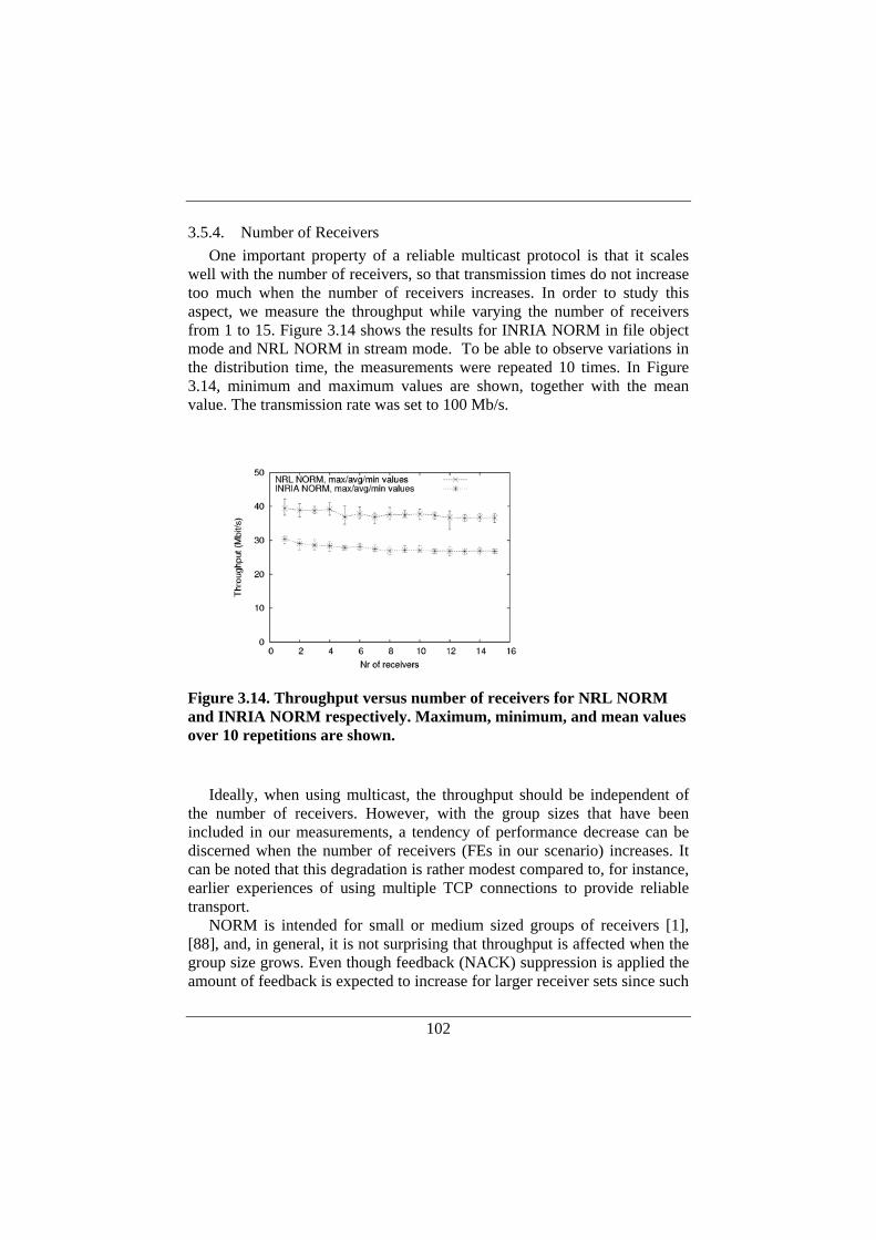
102
3.5.4. Number of Receivers One important property of a reliable multicast protocol is that it scales
well with the number of receivers, so that transmission times do not increase too much when the number of receivers increases. In order to study this aspect, we measure the throughput while varying the number of receivers from 1 to 15. Figure 3.14 shows the results for INRIA NORM in file object mode and NRL NORM in stream mode. To be able to observe variations in the distribution time, the measurements were repeated 10 times. In Figure 3.14, minimum and maximum values are shown, together with the mean value. The transmission rate was set to 100 Mb/s.
Ideally, when using multicast, the throughput should be independent of
the number of receivers. However, with the group sizes that have been included in our measurements, a tendency of performance decrease can be discerned when the number of receivers (FEs in our scenario) increases. It can be noted that this degradation is rather modest compared to, for instance, earlier experiences of using multiple TCP connections to provide reliable transport.
NORM is intended for small or medium sized groups of receivers [1], [88], and, in general, it is not surprising that throughput is affected when the group size grows. Even though feedback (NACK) suppression is applied the amount of feedback is expected to increase for larger receiver sets since such
Figure 3.14. Throughput versus number of receivers for NRL NORM and INRIA NORM respectively. Maximum, minimum, and mean values over 10 repetitions are shown.
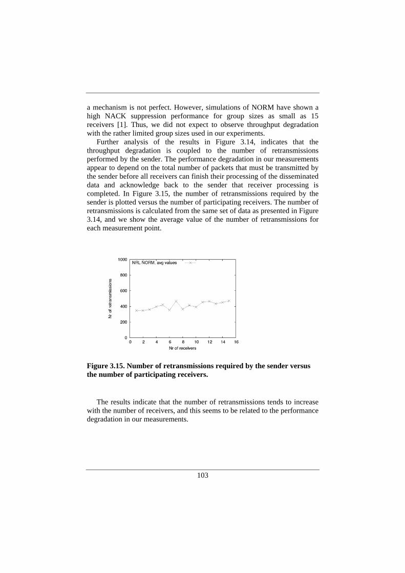
103
a mechanism is not perfect. However, simulations of NORM have shown a high NACK suppression performance for group sizes as small as 15 receivers [1]. Thus, we did not expect to observe throughput degradation with the rather limited group sizes used in our experiments.
Further analysis of the results in Figure 3.14, indicates that the throughput degradation is coupled to the number of retransmissions performed by the sender. The performance degradation in our measurements appear to depend on the total number of packets that must be transmitted by the sender before all receivers can finish their processing of the disseminated data and acknowledge back to the sender that receiver processing is completed. In Figure 3.15, the number of retransmissions required by the sender is plotted versus the number of participating receivers. The number of retransmissions is calculated from the same set of data as presented in Figure 3.14, and we show the average value of the number of retransmissions for each measurement point.
The results indicate that the number of retransmissions tends to increase
with the number of receivers, and this seems to be related to the performance degradation in our measurements.
Figure 3.15. Number of retransmissions required by the sender versus the number of participating receivers.
104
3.6. Discussion In the previous sections, communication overhead in terms of distribution
times as well as overall performance evaluations have been presented. This section discusses the relevance of the results that have been presented.
3.6.1. Communication Overhead To assess the results of our measurements, it is relevant to make a
comparison with local routing updates. However, the update time is strongly dependent on the way in which the routing table is implemented. In addition, much of the previous work in this area focuses on the address lookup problem, and does not primarily deal with issues related to table updates.
For hardware-based routing tables, a popular device is the ternary content-addressable memory (TCAM). A TCAM often requires the routing table to be sorted according to prefix length. This means that TCAMs can suffer from relatively long update times, which require O(N) memory operations, where N is the number of entries in the table. However, by using algorithmic methods for TCAM management it is possible to devise update schemes with O(L) memory operations, where L is the width of addresses [101]. Thus, with TCAM access times in the range of 10 to 100 nanoseconds, it appears possible to perform TCAM updates in the microsecond range. However, this only accounts for the actual accesses to the TCAM. In addition, these methods require the use of separate data structures that keep track of the layout of the routes in the TCAMs. Those data structures also need to be updated, and since they most likely reside in DRAM memory, it appears that they may take at least as much time as the TCAM updates.
The update time together with high power consumption are often claimed to be limitations of the TCAM technology, which has motivated research on alternative solutions. One hardware design that uses regular SRAMs instead of TCAMs is described by Taylor et al [104]. This design is claimed to be able to support up to 100,000 updates per second, with only modest degradations in lookup performance.
The shortest distribution time we have reached in our measurements is around 1.6 seconds for 100,000 updates, or 16 microseconds per update (with NRL NORM as well as with hand-tuned UDP multicast). In other words, we have been able to achieve distribution times that are of the same order of magnitude as update times for sophisticated hardware implementations. These results are encouraging, since they indicate that the overhead costs are not so high that they would preclude a decentralized design. On the contrary, a decentralized design appears to be feasible even for advanced, high-performance routers.
105
3.6.2. Overall Performance Using NORM The receivers are slower than the sender in our distributed router setup,
which has large influence on the protocol for route distribution. In particular, the protocol needs to provide mechanisms to deal with packet losses due to receiver buffer overflow. We believe that this situation is not specific to our configuration. In general, it is not uncommon that receivers are more complex than senders: a receiver needs to analyze the received data in order to verify its validity, and to decide what operations to perform on the data. So we believe that our results are relevant for other distributed systems as well that are based on high-speed networks, where the links are faster than the processing nodes.
Based on the experiments we have conducted we argue that NORM is a better choice for this kind of application compared to alternatives like multiple TCP connections and UDP with user-configured rate control over IP multicast. The former has poor scaling properties and the latter is not a general solution. User-configured rate control means that the rate has to be hand-tuned for the specific scenario. Still, it should be noted that it is NORM that limits the performance in the distributed application we have studied. This is somewhat unexpected since the distributed application in our case, and specifically the receivers, are rather complex in their nature when it comes to data processing, memory accesses, and operating system activities.
It has been claimed that NORM is a complex protocol [88], which is also indicated by the fact that NORM seems to be the main limiting factor in our scenario. Compared with TCP, which also is a complex protocol, the number of implementations available for experiments is very low. TCP has been extensively studied over the years and modern TCP implementations are very efficient. It is possible that NORM software implementations may evolve to become more efficient and therefore yield higher throughput.
Finally, it may be of interest to compare the distributed application we have studied with its centralized counterpart. For such a comparison we have made performance measurements also for local routing updates by letting the CE install the routes locally (i.e., in its operating system kernel) instead of distributing the routes to the FEs. In this experiment we observed a throughput of roughly 43 Mbit/s. This is well below the best performance of 70 Mbit/s that could be achieved with UDP, and the experiment indicates that we achieve a degree of parallelism in the distributed router where route installation is performed by the FEs. It can also be noted that even though NORM appears to be a limiting factor in the distributed application, the overall performance is still almost as good as in the centralized counterpart.
106
3.7. Conclusions and Further Work In this chapter, we have investigated an emerging protocol for reliable
multicast, NORM, as a transport mechanism for internal communication in decentralized routers. In particular, we have studied NORM’s suitability for distribution of route updates using two different implementations: INRIA NORM and NRL NORM. We have studied the communication overhead introduced by a protocol like NORM as well as the overall performance with real forwarding elements acting as multicast receivers.
3.7.1. Communication Overhead We have investigated transmissions based on NORM’s file object and
stream object data representations. The file object representation gives high throughput, but requires all route updates to be present before the transmission starts. This does not fit well with the way in which route updates occur in real life, so the file object representation appears less suitable for our application.
The stream object representation, which is implemented in NRL NORM, provides support for reliable distribution of a continuous stream of data. This representation fits better with route updates, and gives short update times provided that appropriate protocol configuration choices are made.
In both cases, our measurements yield results that are close to an ideal, hand-tuned UDP multicast. However, a certain amount of protocol tuning is required to obtain optimal performance. NORM has more overhead than regular unreliable UDP multicast, but the measurements on our system do not indicate a significant performance penalty for this.
3.7.2. Overall Control Plane Performance We have investigated the performance of a multicast data distribution
application in the context of a distributed router. Such a system is characterized by an internal high-speed network, where the communication links are faster than the processing nodes, and by having receivers that are slower than the senders. We argue that for such a system, a reliable multicast protocol is suitable in order to distribute data from a sender node to many receiver nodes. Neither TCP nor UDP multicast work well in this environment: With TCP, the limited I/O capacity of the nodes gives a total transmission time that is directly proportional to the number of receivers, so it does not scale well. UDP multicast, on the other hand, is too fast, and causes packet losses at the receivers.
We have performed experimental studies with two implementations of NORM, from INRIA and NRL, and found that there are significant
107
performance penalties compared to the ideal case with UDP. The results indicate that the stream-mode implemented in NRL is better suitable for our implementation, compared to INRIA NORM’s file object mode.
The basic problem we are addressing is simple: we need to protect multicast receivers from buffer overflow. Our experiments indicate that the price for using NORM for flow control might be rather high, which prompts the question whether it would be possible to design a simpler reliable multicast protocol that is optimized for this kind of applications?
We have used user-configured rate control, and for further work it would be interesting to study the effect of adaptive transmission rate for congestion control. Both TCP-like congestion control and multi-rate (layered) control mechanisms have been simulated and analytically studied by others [15]. We believe that comparisons with experimental studies in our environment could further contribute to the understanding of reliable multicast for distributed systems.
Furthermore, we have used NACKs as the sole mechanism for error control. NORM also provides support for error control through forward error correction, and it would be interesting to study the performance of NACKs in combination with FEC under different packet loss scenarios.

108
109
4. DISTRIBUTED CONTROL The number of new services required in IP routers is continuously
growing. New services often require new protocols in the routers, thus leading to an increased complexity in the control plane—the software controlling the router. It is reasonable to assume that this development calls for increased capacity of the control plane, since it has to perform more tasks. An increased complexity can also make the control plane more error prone. The main purpose of this chapter is to investigate how the control plane can be improved when it comes to robustness under the occurrence of control plane faults as well as when it comes to control plane performance under heavy load.
The traditional structure of the control plane is that all router control software runs on one processing unit, normally denoted the control processor or the routing processor. The starting point for our investigation is that this centralized monolithic control plane architecture constitutes a design weakness and that new solutions should be sought. Instead, the ideas presented in this chapter aim at a distributed router architecture where control functions as well as forwarding functions can be located to a set of processing elements, possibly of different types, in a distributed fashion. Such a distributed architecture opens up for several new design opportunities. For instance, in such an environment, the control software could be partitioned into many independent modules which are executed independently on different processing elements within the router.
We claim that modularization and decentralization of the control plane have several advantages. One possibility with control plane modularization and decentralization is to functionally separate, for instance, different routing protocols and let them be executed on different processing elements. The modularization can be taken even further so that e.g., a particular routing protocol is partitioned into modules that can interoperate to form the complete functionality of the protocol. We believe that both control plane performance and availability can be significantly improved with such a modular and decentralized design. Performance is improved because modules can be replicated and added as capacity requirements increase. Availability is mainly due to two factors: First, the modularity makes it possible to use redundancy and replication of critical functionality over multiple modules. Second, the modular structure in itself tends to limit the impact of faults in individual modules, and encourages sound engineering design principles.
It is not our proposal that all control plane software should be rewritten from scratch to work in such a distributed environment. Instead, we argue
110
that existing software should be modularized so that modules can be executed concurrently on different processing elements and communicate over well-defined protocols and interfaces.
This chapter is organized as follows. Section 4.1 discusses motivations for a distributed control plane and related work. Thereafter, Section 4.2 deals with approaches for modularization and decentralization of the router control plane. Section 4.3 identifies requirements on internal support from our distributed router architecture to support modularization and decentralization. This is followed by a description of internal mechanisms for the design and implementation of a distributed control plane in Section 4.4. In Section 4.5, we have applied our ideas to a specific control plane service, namely BGP, and a performance evaluation of the distributed BGP implementation is made in Section 4.6. Finally, conclusions and further work are outlined in Section 4.7.
4.1. Related Work Related work has been conducted in the area of control plane
modularization, for instance within the framework of XORP (eXtensible Open Router Platform) [44], [45]. The primary goal of XORP is extensibility and the software design allows experimentation with new protocols and protocol features. Regarding modularization, XORP is a multi-process architecture using one process per routing protocol and additional processes for other control plane functions, such as management and configuration. Moreover, BGP and the routing information base (RIB), used by BGP and other routing protocols, have been modularized into separate processes to obtain extensibility of the BGP implementation [45]. Still, to our understanding, the experimental work with the XORP control plane has been limited to one single CPU executing all the control plane processes. As shall be seen later (in Section 4.5), our modularization of BGP differs from the XORP design, and the main contribution of our work lies in the distribution of functional modules of the control plane to multiple processing elements. However, we do not rule out the possibility to combine XORP with our decentralized control plane in the future.
Another example of related work in this area is the distributed control plane (DCP) architecture, suggested by Deval et al [25]. They claim that the complexity of the control plane increases, and they have observed that the amount of control traffic increases. The latter can be explained by the large number of routers present in a typical Internet service provider (ISP) network. There can be several hundreds of IP routers in such a network [10], meaning that control information may be exchanged with hundreds of peers. To deal with this increasing burden on the control plane, a software
111
framework that supports the distribution of control plane software parts onto the forwarding planes is suggested. To evaluate the architecture the open shortest path first routing protocol (OSPF) [83] has been used as an example. Apart from exchanging routing database information and computing the shortest path to other routers, OSPF uses a Hello protocol to establish and maintain relationships with its neighbors. It turns out that this Hello protocol can cause high load on the control plane in real ISP networks consisting of hundreds of routers, especially during changes in the network state. This situation is claimed to be aggravated when the Hello interval time is decreased to the subsecond range [25] (current OSPF implementations recommend a Hello timer value of 10 seconds and a Router Dead Interval of 40 seconds, meaning that an OSPF neighbor is considered dropped if no Hello messages have been received from it within the last 40 seconds).
Experiments with subsecond Hello timer intervals have been done to improve network convergence times [10]. As a result, the DCP architecture suggests that the processing of Hello messages is offloaded onto the FEs. Apart from relieving the processing burden from the control plane, this is meant to scale well with an increasing number of line cards, since an FE only processes the Hello messages that are received on its particular interfaces. It should however be noted that others have claimed that the overhead from processing Hello messages is low, even when the time interval is as low as 250 ms [10]. Instead, it is argued that the problem with subsecond time intervals is rather the processing of routing database information due to an increasing number of route flaps. From a control plane processing perspective, it can thus be questioned if pushing the processing of OSPF Hello messages onto specialized forwarding hardware makes a significant improvement.
Distributed control plane processing has also been used to provide a redundant structure on routing modules [48]. In this case, an active OSPF routing manager is used together with a similar back-up module which is ready to take over when the primary fails. The active routing manager receives incoming OSPF messages and duplicates them to the back-up module. The back-up module builds its own routing data base, but does not communicate with neighboring routers as long as it is in back-up mode. When the active routing manager fails, the back-up takes over its role and uses the routing database that has been created based on the earlier duplicated packets from the active routing manager.
Both OSPF and BGP fit well as examples of how control plane functionality could be improved in terms of performance and robustness through the use of modularization and decentralization. We believe that there is a general need for further research on BGP due to its importance and wide
112
use. BGP is the de facto standard routing protocol for large scale routing on the Internet today, and virtually every full-fledged IP router includes a BGP implementation. Current routing tables can be quite large and the computation of routes in a router's control plane can potentially occupy a routing processor for a significant amount of time. Such intensive route computation takes place when routing is started or restarted but also during normal operation when there are sudden changes in the routing topology.
BGP performs many different tasks and new features are continuously being added to BGP to make it more flexible. It has accordingly been argued that this development of BGP has made it complex and prone to fail [29]. It has also been claimed that, as a consequence of the rich feature set, BGP has become so complicated that it is hard to establish a consistent configuration [27], [37], [75]. One approach to deal with router configuration faults is to use specific tools for this purpose. One example of such a tool is the routing configuration checker (rcc) [28], which uses static analysis to detect faults in the steady state of BGP, potentially caused by misconfigurations.
Meanwhile, the requirements on Internet uptime are becoming more stringent. The Internet is now used for many types of business critical applications and for services with minimal tolerance to service disruption. For instance, IP telephony has started to replace regular telephony and the same high level of availability as that of the public switched telephony network (PSTN) is now more or less expected also from the Internet.
There are several outstanding research issues regarding BGP that we believe could be addressed with a modular and decentralized design approach. Examples of such issues are discussed in the remainder of this chapter.
The current BGP specification (version 4) [95], was first written in 1995 and has recently been updated. According to the original specification all routers within an autonomous system (AS) have to be connected in a full mesh. Due to scaling problems with this restriction, solutions like route reflectors [11] and AS confederations [106] have been introduced. Even though these techniques solve the original scaling problem, they may also introduce instabilities like oscillation and forwarding problems [81], [38]. Several solutions to these problems have been suggested [85], [86], [64], [9], but how to best deal with these issues is still an open question.
The behavior of commercial routers under high BGP load has been investigated earlier [19]. The impact of routing table size was studied, and it was found that there were limitations of how large routing tables that could be handled by certain routers. Furthermore, it was observed that route overloading, i.e., loading large routing tables, might cause routers to fail or oscillate.
113
To summarize, it can be noted that BGP-4 has built-in problems that should be solved to increase the stability, and thus there is still a need for improved BGP robustness. A traditional centralized design approach tends to make the control processor and the control plane software a single point of failure. This problem can be circumvented through the use of redundant units, ready to take over all the work in case of a failure in the primary processing unit.
Another way to increase the robustness is to run several routers in parallel and use election protocols to provide fail-over through the use of a standby router should the master (or active) router become unavailable. There are several such protocols for router redundancy and/or load balancing that has been suggested over the years and also become commercially deployed. Some examples of the most commonly known such protocols are HSRP (Hot Standby Router Protocol) [69], VRRP (Virtual Router Redundancy Protocol) [47], and GLBP (Gateway Load Balancing Protocol) [21].
HSRP provides failover to hosts on a local area network (LAN), when a host’s first hop router fails and the host is incapable of finding a first hop router dynamically. Through HSRP, two or more routers work together to form one single virtual router for the hosts on the LAN. From this group of routers—the HSRP group (or standby group)—one router is elected responsible for forwarding of packets sent through the virtual router. An HSRP group uses a virtual IP address and a virtual MAC address. The virtual IP address is typically configured as the default router in the hosts. The virtual MAC address is advertised to the hosts on the LAN, and IP packets sent to the virtual MAC address are forwarded by the active router in the HSRP group. There can be only one active router in the HSRP group at a time.
VRRP provides a similar function to the proprietary HSRP. In VRRP, the expected duration in master election convergence is quite small, typically well below one second.
A conceptual view of a virtual router serving several hosts in a LAN is given in Figure 4.1.
Typical VRRP scenario is that two routers, R1 and R2, are used. R1 is next-hop router for a set of hosts and backup next-hop for hosts with R2 as their next-hop router, and vice versa. This provides load sharing when both routers are available and full redundancy for robustness. A similar configuration can be done using HSRP.

114
Using multiple virtual router groups to provide load balancing between
routers with VRRP or HSRP constitute an administrative burden since the hosts must be configured for different default gateways. To reduce this burden, GLBP has been promoted as a simpler administrative approach. GLBP is a Cisco proprietary solution for first hop redundancy that provides load balancing over multiple routers by default. GLBP uses one virtual IP address and multiple virtual MAC addresses. Accordingly, all hosts are configured with the same virtual IP address as their default gateway, and all routers in the group participate in the forwarding of packets.
Finally, CARP (Common Address Redundancy Protocol) is another redundancy protocol and it first appeared in OpenBSD 3.5 operating system. It allows multiple hosts on the same LAN to share a set of IP addresses. The main purpose with CARP is to provide failover redundancy, but it can also provide load balancing.
Regarding performance issues of the control plane, it has been recognized that a router can experience bursts of BGP UPDATEs from its peers due to temporary link failures, oscillating routes or route overloading. If such a situation reappears regularly with short intervals and for some reason becomes persistent, route flap dampening (RFD) [107] may be triggered. RFD gives a penalty to a route each time it changes and if it happens too often, that route will not be used in the calculation of the routing table. This means that RFD reduces the number of flaps and BGP UPDATE messages through the Internet, but also in some cases increases convergence times [76]. Bursts of updates can appear at any time during normal operation due to the previously mentioned problems. Therefore, it is important that routers quickly can handle large burst of BGP UPDATEs.
host host host host host host
R1 R2
Virtual IP address
VRRP/HSRP
Figure 4.1. Virtual router providing first hop router redundancy for a set of hosts on a LAN.
115
For the above mentioned reasons, we believe that BGP can be subject to improvements in terms of performance and robustness, and that modularization and decentralization may be means to realize such improvements. The expected result of an experimental study of a modular and decentralized BGP is that route computation and installation can be made faster through the replication of modules and use of load sharing.
4.2. Distributed Control for Redundancy and Load Balancing The protocols for router redundancy and load balancing discussed in the
previous section (Section 4.1) have proven to work in scenarios where packet forwarding should continue despite the failure in a first-hop router. It might be assumed that a similar approach could be taken to make use of multiple CEs in a decentralized router (such as the one depicted in Figure 4.2) for purposes like control plane redundancy and load balancing between CEs. However, redundancy when it comes to packet forwarding is quite different from redundancy of control plane functionality. The forwarding of packets is, in principle, stateless where each IP packet is forwarded independently of the others. This simplifies the failover of packet forwarding from an active router to a backup router should the active router fail. There is no control plane handover involved when the forwarding of packets is taken over by a backup router in HSRP or VRRP. Using Figure 4.1 as an example, both R1 and R2 run their own control plane and maintain peer-to-peer contact with routers on the other side of the LAN. As a consequence, both R1 and R2 will have forwarding tables that are up-to-date as long as the routing protocols operate properly.
A CE, on the other hand, typically has application level endpoints where session level state with external peers is maintained. This is illustrated in Figure 4.2, where a decentralized router with a control plane distributed over multiple CEs is peering with a remote router. We refer to the networking applications as services, and examples of such services are routing protocols like BGP, OSPF, IS-IS, etc. Further, we will refer to redundancy of a control plane function, like BGP, as service redundancy.
An example of a control plane peering scenario is the formation of routing adjacencies (such as OSPF or BGP) between the CE and an external remote router.
To leverage on the decentralized modular architecture with multiple CEs, we identify several requirements when it comes to redundancy and load balancing.
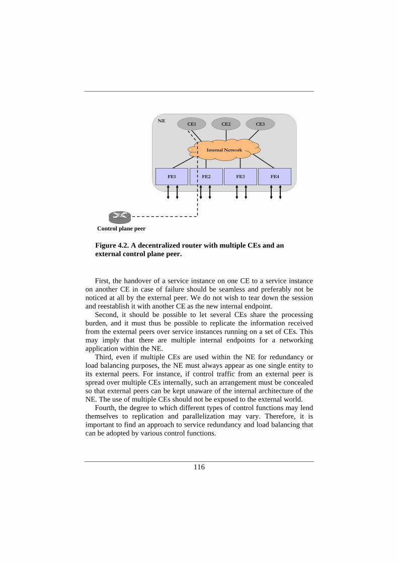
116
First, the handover of a service instance on one CE to a service instance
on another CE in case of failure should be seamless and preferably not be noticed at all by the external peer. We do not wish to tear down the session and reestablish it with another CE as the new internal endpoint.
Second, it should be possible to let several CEs share the processing burden, and it must thus be possible to replicate the information received from the external peers over service instances running on a set of CEs. This may imply that there are multiple internal endpoints for a networking application within the NE.
Third, even if multiple CEs are used within the NE for redundancy or load balancing purposes, the NE must always appear as one single entity to its external peers. For instance, if control traffic from an external peer is spread over multiple CEs internally, such an arrangement must be concealed so that external peers can be kept unaware of the internal architecture of the NE. The use of multiple CEs should not be exposed to the external world.
Fourth, the degree to which different types of control functions may lend themselves to replication and parallelization may vary. Therefore, it is important to find an approach to service redundancy and load balancing that can be adopted by various control functions.
FE1 FE2 FE3
Internal Network
FE4
CE2 CE3NE
Control plane peer
CE1
Figure 4.2. A decentralized router with multiple CEs and an external control plane peer.
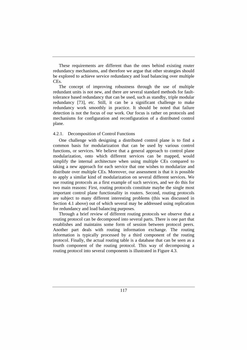
117
These requirements are different than the ones behind existing router redundancy mechanisms, and therefore we argue that other strategies should be explored to achieve service redundancy and load balancing over multiple CEs.
The concept of improving robustness through the use of multiple redundant units is not new, and there are several standard methods for fault-tolerance based redundancy that can be used, such as standby, triple modular redundancy [73], etc. Still, it can be a significant challenge to make redundancy work smoothly in practice. It should be noted that failure detection is not the focus of our work. Our focus is rather on protocols and mechanisms for configuration and reconfiguration of a distributed control plane.
4.2.1. Decomposition of Control Functions One challenge with designing a distributed control plane is to find a
common basis for modularization that can be used by various control functions, or services. We believe that a general approach to control plane modularization, onto which different services can be mapped, would simplify the internal architecture when using multiple CEs compared to taking a new approach for each service that one wishes to modularize and distribute over multiple CEs. Moreover, our assessment is that it is possible to apply a similar kind of modularization on several different services. We use routing protocols as a first example of such services, and we do this for two main reasons: First, routing protocols constitute maybe the single most important control plane functionality in routers. Second, routing protocols are subject to many different interesting problems (this was discussed in Section 4.1 above) out of which several may be addressed using replication for redundancy and load balancing purposes.
Through a brief review of different routing protocols we observe that a routing protocol can be decomposed into several parts. There is one part that establishes and maintains some form of session between protocol peers. Another part deals with routing information exchange. The routing information is typically processed by a third component of the routing protocol. Finally, the actual routing table is a database that can be seen as a fourth component of the routing protocol. This way of decomposing a routing protocol into several components is illustrated in Figure 4.3.
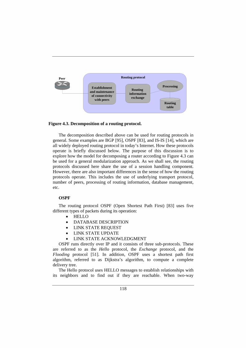
118
The decomposition described above can be used for routing protocols in general. Some examples are BGP [95], OSPF [83], and IS-IS [14], which are all widely deployed routing protocol in today’s Internet. How these protocols operate is briefly discussed below. The purpose of this discussion is to explore how the model for decomposing a router according to Figure 4.3 can be used for a general modularization approach. As we shall see, the routing protocols discussed here share the use of a session handling component. However, there are also important differences in the sense of how the routing protocols operate. This includes the use of underlying transport protocol, number of peers, processing of routing information, database management, etc.
OSPF
The routing protocol OSPF (Open Shortest Path First) [83] uses five different types of packets during its operation:
• HELLO • DATABASE DESCRIPTION • LINK STATE REQUEST • LINK STATE UPDATE • LINK STATE ACKNOWLEDGMENT
OSPF runs directly over IP and it consists of three sub-protocols. These are referred to as the Hello protocol, the Exchange protocol, and the Flooding protocol [51]. In addition, OSPF uses a shortest path first algorithm, referred to as Dijkstra’s algorithm, to compute a complete delivery tree.
The Hello protocol uses HELLO messages to establish relationships with its neighbors and to find out if they are reachable. When two-way
Peer
Processing
Routingtable
Routing information
exchange
Establishmentand maintenance
of connectivitywith peers
Routing protocol
Figure 4.3. Decomposition of a routing protocol.

119
connectivity between two OSPF peers has been established through the Hello protocol, their databases must be synchronized. An initial synchronization is done over the Exchange protocol in a master-slave fashion where DATABASE DESCRIPTION messages are used both by the master and the slave to give an outline of its database.
The purpose of the Flooding protocol is to advertise the state of an OSPF router’s links, i.e., connections of different types, to all other OSPF participants in the network. The Flooding protocol is based on LINK STATE UPDATE packets. This can be seen as the main part of OSPF operation, and is used to exchange the actual routing information which is used to compute the shortest path. The LINK STATE REQUEST and the LINK STATE ACKNOWLEDGMENT are used by OSPF to query information about specific routes and to acknowledge the receipt of a LINK STATE UPDATE respectively.
In the context of mapping OSPF to our decomposition model, the Hello protocol would typically constitute the module responsible for establishment and maintenance of connectivity with peers. The Exchange and Flooding protocols belong to the routing information exchange module. The path computation based on Dijkstra’s algorithm, finally, belongs to the processing module.
IS-IS
The routing protocol IS-IS (Intermediate System to Intermediate System) [14] has several similarities with OSPF. IS-IS is a link state routing protocol using the same shortest path first algorithm (Dijkstra) to compute the shortest path to other routers participating in the IS-IS routing.
Like OSPF, IS-IS consists of different sub-protocols. A Hello protocol is used to discover neighbors. Hello messages are sent regularly to check a link’s availability. The flooding and exchange of link state records is taken care of by another protocol.
As a consequence of the similarities with OSPF operation, we believe that the same type of decomposition can be applied to IS-IS.
BGP
The routing protocol BGP-4 (Border Gateway Protocol) [95] specifies four messages:
• OPEN • UPDATE • KEEPALIVE • NOTIFICATION
120
The OPEN message is used to set up a BGP session, KEEPALIVEs are sent at negotiated intervals to keep the session open and also to confirm the open session. UPDATE messages contain various data related to routes, such as withdrawn routes and/or new routes. The NOTIFICATION message is used to notify the peer about errors or when a session is being closed.
BGP uses TCP as the transport protocol and using a reliable transport protocol generally simplifies the application level protocol (i.e., BGP in this case) since it can be safely assumed that BGP messages will reach the remote end uncorrupted and in order.
BGP lends itself to decomposition according to Figure 4.3 in the following straight-forward fashion. BGP routing information is exchanged between two BGP peers over a session—a TCP connection. Accordingly, the main responsibility of the module responsible for connectivity between routing peers would be to establish and maintain this session with external peers. Furthermore, the routing information exchange module basically deals with UPDATE messages between the processing module and external BGP peers. The main responsibility of the processing module is to process incoming UPDATE messages, compute the routing table, and generate outgoing UPDATE messages.
The decomposition of BGP based on modularization and decentralization is further described in 4.5.
4.2.2. Modularization Approach Our general modularization approach is to decouple the session
establishment and maintenance from the software forming the actual routing protocol implementation. We refer to the former part as the session manager and to the latter part as the service process. This modularization is illustrated in Figure 4.4.
Decoupling session management from the processing of control information into a separate functional module has several benefits. Compared to routing information exchange and routing table computation, the session manager can be kept rather simple and would typically not be subject to advanced configuration. As a result it should be less prone to fail, which is advantageous considering that the session manager is the module that exposes the application end-point (such as the one used in a BGP session) to an external peer.
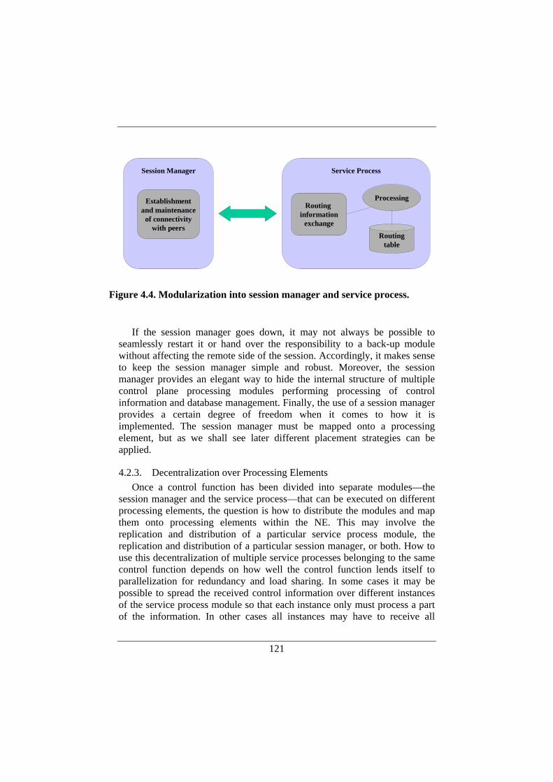
121
If the session manager goes down, it may not always be possible to
seamlessly restart it or hand over the responsibility to a back-up module without affecting the remote side of the session. Accordingly, it makes sense to keep the session manager simple and robust. Moreover, the session manager provides an elegant way to hide the internal structure of multiple control plane processing modules performing processing of control information and database management. Finally, the use of a session manager provides a certain degree of freedom when it comes to how it is implemented. The session manager must be mapped onto a processing element, but as we shall see later different placement strategies can be applied.
4.2.3. Decentralization over Processing Elements Once a control function has been divided into separate modules—the
session manager and the service process—that can be executed on different processing elements, the question is how to distribute the modules and map them onto processing elements within the NE. This may involve the replication and distribution of a particular service process module, the replication and distribution of a particular session manager, or both. How to use this decentralization of multiple service processes belonging to the same control function depends on how well the control function lends itself to parallelization for redundancy and load sharing. In some cases it may be possible to spread the received control information over different instances of the service process module so that each instance only must process a part of the information. In other cases all instances may have to receive all
Establishmentand maintenance
of connectivitywith peers
Session Manager
Processing
Routingtable
Routing information
exchange
Service Process
Figure 4.4. Modularization into session manager and service process.
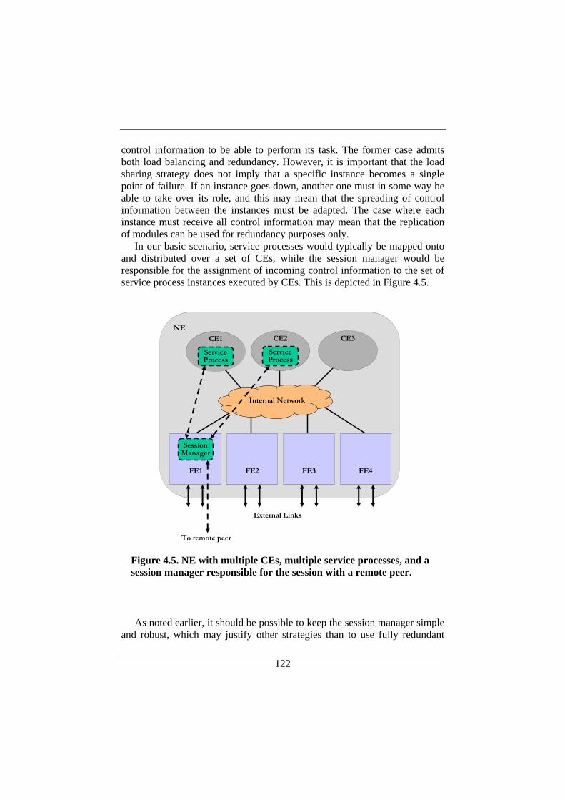
122
control information to be able to perform its task. The former case admits both load balancing and redundancy. However, it is important that the load sharing strategy does not imply that a specific instance becomes a single point of failure. If an instance goes down, another one must in some way be able to take over its role, and this may mean that the spreading of control information between the instances must be adapted. The case where each instance must receive all control information may mean that the replication of modules can be used for redundancy purposes only.
In our basic scenario, service processes would typically be mapped onto and distributed over a set of CEs, while the session manager would be responsible for the assignment of incoming control information to the set of service process instances executed by CEs. This is depicted in Figure 4.5.
As noted earlier, it should be possible to keep the session manager simple
and robust, which may justify other strategies than to use fully redundant
Internal Network
NE
External Links
To remote peer
FE1 FE2 FE3 FE4
SessionManager
CE1
ServiceProcess
CE2
ServiceProcess
CE3
Figure 4.5. NE with multiple CEs, multiple service processes, and a session manager responsible for the session with a remote peer.
123
modules in the same style as we propose for the service process. However, session management does not necessarily have to be implemented as one single process. In addition, different internal placements of a session manager could be considered: it could be located either in an FE or in a CE. In Figure 4.5 above, we show an example where the session manager is mapped to an FE. How to locate the session manager and whether to replicate it or not depend on the operation of the specific control function that is modularized and distributed within the NE as well as on the level of redundancy that is to be achieved. The replication of the session manager module may also have to be traded off against complexity of the solution as a whole.
A detailed description of how to design and implement distributed control plane functions consisting of multiple service processes and session managers is given later in this chapter, but for an overview discussion around different faults that may occur and for which protection may be required, we refer again to Figure 4.5. The figure illustrates a session manager that has established communication with an external remote peer, and also with two service processes that runs on two different CEs (CE1 and CE2). We identify and discuss the following faults: service process failure, FE failure, link failure, and session manager failure.
The situation with a failing service process is straight-forward: If the service process module executed by CE1 fails, the service process module on CE2 should be capable of taking over its tasks. This is the main type of failure that is addressed with our architecture for distributed control and we believe that this is the most likely failure from a software perspective. The reason behind this assumption is that the service process is much more complex than the session manager and thereby likely to be more unstable. The service process may also be subject to complicated configuration, which may lead to erroneous behavior.
FE failures and link failures lead to other types of recovery scenarios, which may have to be dealt with on a case by case basis depending on the type of control function that has been modularized and decentralized into service processes and session managers. For instance, in Figure 4.5, if the link or the complete FE over which the session manager communicates goes down, the session manager will loose connectivity with the remote external peer. For some control functions it may be advantageous to try to re-establish the session to the remote peer quickly over another link (and possibly over another FE), or in some way transfer the session to go over a new link or FE. For other control functions, like certain routing protocols, the session may better be left in the terminated state in order not to disturb the operation of the routing protocol. The reason for this is that in some
124
cases the problem of a failing link is better dealt with by the routing protocol.
It is also possible to replicate the session manager, for instance with the purpose to minimize the effect of a failing session manager. For some control functions, a design choice may be to use one session manager per session. This would mean that a failing session manager would basically result in lost connectivity with only one peer. Sessions established with other peers would not be affected by the failing session manager. Session manager could further be mapped onto FEs. An advantage with such an approach would be that specialized hardware in the FE could potentially be used for extensive session level processing, if needed. An example of such processing is authentication for security reasons.
Replicated session managers could also be used for the pure redundancy to avoid making the session manager a single point of failure. An important challenge with redundant session managers is to switch over the session from to a back-up session manager without exposing this action to the remote external peer and without unnecessary disturbance of the internal service process modules executing on the CEs within the NE. The difficulties related to migrating the session over to a back-up session manager depends on the amount of state that is kept within the session manager. For example, if the session manager is completely stateless and simply performs the task of relaying packets between the service processes and the external remote peer, the session switch-over is mainly a question of detecting the failure of a session manager and of making the CEs and FEs redirect the IP packets belonging to the particular session to the back-up session manager. However, for some services it is likely that the session manager holds a certain amount of state, maybe both at the application level and at the transport protocol level through the use of TCP. The support required for session manager fail-over and seamless migration of established sessions from a primary session manager to a back-up unit in our distributed control plane architecture is further discussed in 4.3.
4.3. Internal Requirements for Distributed Control To realize the distributed control architecture, appropriate support from
the internal protocols is needed. This involves the Forz protocol as well as additional inter-process communication that may be needed between service processes and session managers. The purpose with this section is to identify the requirements on the internal protocols in terms of protocol messages and protocol operation. To do this, we study the basic scenarios resulting from the decoupling of session managers from control processing in terms of service processes. In these scenarios, service process modules are mapped
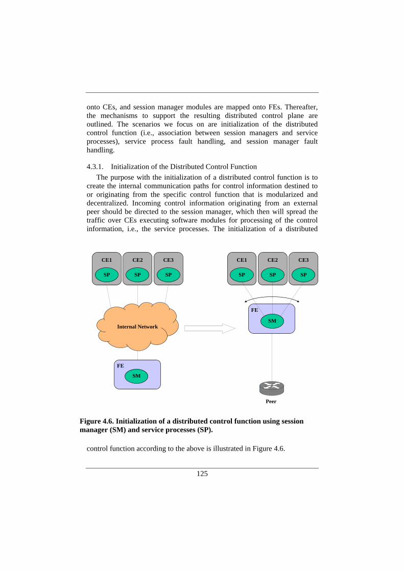
125
onto CEs, and session manager modules are mapped onto FEs. Thereafter, the mechanisms to support the resulting distributed control plane are outlined. The scenarios we focus on are initialization of the distributed control function (i.e., association between session managers and service processes), service process fault handling, and session manager fault handling.
4.3.1. Initialization of the Distributed Control Function The purpose with the initialization of a distributed control function is to
create the internal communication paths for control information destined to or originating from the specific control function that is modularized and decentralized. Incoming control information originating from an external peer should be directed to the session manager, which then will spread the traffic over CEs executing software modules for processing of the control information, i.e., the service processes. The initialization of a distributed
control function according to the above is illustrated in Figure 4.6.
CE1
SP
CE2
SP
CE3
SP
FE
Peer
SM
CE1
SP
CE2
SP
CE3
SP
FE
SM
Internal Network
Figure 4.6. Initialization of a distributed control function using session manager (SM) and service processes (SP).

126
As illustrated in the figure, incoming traffic destined to the distributed control function must be redirected to the session manager for further distribution to the service processes. Moreover, the corresponding outgoing control traffic from the service processes must be sent through the session manager for further relaying to the external peer. This means that this particular control traffic must be directed by the CEs to the FE executing the session manager.
To achieve this, session managers and service processes must register with the Forz protocol when they are started. This registration will allow the participating processing elements (CEs and FEs) to inform each other of their capabilities and responsibilities through the Forz protocol. Processing elements must have this information to be able to direct service-specific traffic correctly within the NE.
During the registration the session manager informs the FEs and CEs about its capabilities, i.e., for which service (such as BGP or OSPF) the session manager can be used. Each FE will then set up a filter for incoming traffic matching the port number (which may be either “well-known” or configured) for the specific service and the local IP address of the distributed router itself so that this traffic can be redirected to the session manager. The session manager will have an address on the NE’s internal network since it is mapped to a processing element within the NE, namely to an FE.
Moreover, service processes and session managers must register with each other since they cooperate to provide a certain service in the NE. During this procedure, the session manager will be associated with the service processes for which it handles the sessions with external peers. Depending on the service and how well it lends itself to parallelization, different strategies for spreading the control traffic over multiple service processes may be used by the session manager.
Additional internal support that is needed is that Forz may have to deal with issues like address translation. On a logical level, a service process executing on a CE will establish a session to an external IP address belonging to the remote peer. However, the introduction of a session manager internally within the NE means that the session will be split in two parts: one internal part between the CE and the session manager and one external part between the session manager and the remote peer. The former part is established between internal IP addresses within the NE. The service process communicates with an external peer, and thus the logical remote endpoint for the session is an external IP address. How to deal with this two-step session from the view of the service process is a design choice and have to be dealt with on a case-by-case basis depending on the actual service. It may be preferable to conceal the use of an intermediate internal IP address
127
for the communication between the service process and its remote peer. One way to accomplish this is to let the Forz protocol perform address translation. Recall that Forz is used to tunnel data packets that are sent from a CE to the external world or vice versa (see Chapter 2, Section 2.5.3). Accordingly, Forz may redirect data packets destined to the remote external peer to the corresponding session manager by translating IP address and port numbers so that the session manager is addressed instead of the remote external peer. This issue will be discussed in more detail in Section 4.5, where modularization into session manager and service module has been applied to BGP.
In addition to Forz level support like address translation, there is need for direct inter-process communication between the service processes and the session managers. Therefore, the service process should be designed to use the proxy functionality provided by the session manager. The service process thus maintains both inter-process communication state related to the session manager and end-to-end state related to its remote peer. The direct inter-process communication may be needed for instance to let a session manager inform a set of service processes about their responsibilities when it comes to sharing workload, primary versus back-up mode, etc. There must also be a way for session managers to detect that a service process has crashed to be able to reassign workload between the remaining service processes and to invoke service processes that may run in backup mode.
4.3.2. Service Process Fault Handling The main intention with service process fault handling is to ensure that a
service continues to run without disruption despite the occurrence of either a fatal software error in one of the software modules implementing the service, i.e., the service process itself, or a crashing CE. For both these types of errors two actions must be taken by the remaining involved parties: First, the session manager should change the way it dispatches control information destined to the specific service so that the information is distributed only to the remaining instances of the service process. Second, the remaining service process instances must, according to some strategy, cover up for the failed instance. The control traffic dispatching mechanism of the session manager must not be constructed in a fashion that requires all service processes to be up in order to provide the service. The scenario of a failing service process is depicted in Figure 4.7.

128
At the Forz level, the failure of a CE is detected through the association part of the Forz protocol, which is capable of detecting dynamic changes between CEs and FEs within the NE (see Section 2.5.1).
At the service level, there are different alternatives for the session manager to detect that a service process is down. One way to discover this is through the absence of session maintenance communication. In that case, we rely on the same session level mechanism that is used between service level peers, e.g., BGP KEEPALIVE messages or OSPF HELLO messages for the internal detection of a crashed service process. The absence of this type of messages will then trigger the session manager to adapt the dispatching of control messages. Two shortcomings with this approach can be identified. First, the internal discovery of a failing service process will occur on the same time scale as the peer-to-peer detection of the failure. Accordingly, it may not be possible to perform service process failover inside the NE without any reactions from the remote external service peer. Second, depending on the service and the modularization approach it may be desirable to relieve the service process from the burden of processing session level maintenance communication.
FE
Peer
SM
CE
SP1
CE
SP2
CE
SP3
FE
Peer
SM
CE
SP1
CE
SP2
CE
SP3
Figure 4.7. Service process fault handling.
129
For these reasons, we use an internal heartbeat mechanism between service processes and session managers that is independent of the session maintenance communication with external remote peers. The internal mechanism could be part of the required inter-process communication used for the distributed service inside the NE, or it could be based on the Forz level heartbeat mechanism.
Once a failing service process has been detected, it is up to the session manager to recalculate how the workload should be split between the remaining service processes and also to inform a service process of a possible change in responsibility, such as going from passive to active mode for parts of the service (or for the complete service in cases when load sharing is not applied).
As an example, consider a case where SP1, SP2, and SP3 in Figure 4.7 are responsible for one third each of the work and receive one third each of the incoming control traffic according to some dispatching algorithm. Further, SP1 can serve as backup for SP2, SP2 as a backup for SP3, and SP3 as a backup for SP1. Now, assume that SP3 goes down, as in the figure. This will be detected by the session manager, which will inform SP1 and SP2 about the incident. As a result, SP2 will immediately take over the responsibilities of SP3 and thus perform two thirds of the work temporarily. Meanwhile, the session manager will rerun the dispatching algorithm and calculate a new fair load sharing where SP1 and SP2 perform half the work each and act as backup for the other half of the work.
The operation of detecting the service process failure and adapting the workload dispatching can be taken care of by the direct inter-process communication between session manager and service processes.
4.3.3. Session Manager Fault Handling As previously mentioned, multiple session managers can be used in
different ways depending on the strategy for how to map session managers onto processing elements. For instance, having one session manager per external peer may be a typical strategy to limit the damage of a failing session manager. Still, it may be desirable also to replicate a session manager for redundancy purposes. In this section we restrict the discussion to the case where a back-up session manager is used as a fall-back when a session manager goes down. Consequently, this means that the back-up session manager must take over communication both internally with the involved service processes, and externally with the remote peer(s). This is illustrated in Figure 4.8.
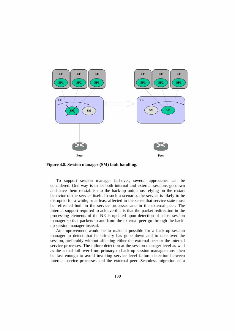
130
To support session manager fail-over, several approaches can be
considered. One way is to let both internal and external sessions go down and have them reestablish to the back-up unit, thus relying on the restart behavior of the service itself. In such a scenario, the service is likely to be disrupted for a while, or at least affected in the sense that service state must be refreshed both in the service processes and in the external peer. The internal support required to achieve this is that the packet redirection in the processing elements of the NE is updated upon detection of a lost session manager so that packets to and from the external peer go through the back-up session manager instead.
An improvement would be to make it possible for a back-up session manager to detect that its primary has gone down and to take over the session, preferably without affecting either the external peer or the internal service processes. The failure detection at the session manager level as well as the actual fail-over from primary to back-up session manager must then be fast enough to avoid invoking service level failure detection between internal service processes and the external peer. Seamless migration of a
FEFE
SM SM
Peer Peer
SMSM
CE
SP1
CE
SP2
CE
SP3
CE
SP1
CE
SP2
CE
SP3
Figure 4.8. Session manager (SM) fault handling.

131
session in this scenario constitutes an extra challenge for services using TCP as the transport protocol. Seamless migration of a TCP connection from a failing server to back-up server is a research issue in itself and techniques for TCP connection failover have been suggested and implemented earlier [4], [103], [112].
Two examples of failover mechanisms for TCP are M-TCP (Migratory TCP) [103] and FT-TCP (Fault-tolerant TCP) [4]. The purpose of M-TCP is to perform migration of the TCP endpoint at the server side in transparent fashion, so that the service can continue to operate with a new endpoint. A drawback with M-TCP is that the client side initiates the migration of the connection. This means that if M-TCP is used to seamlessly move TCP connections from a primary session manager to a backup unit, M-TCP must be implemented also at the remote external peer. It is very unlikely that this is the case in practice. With FT-TCP, the TCP connections of a faulty process can be kept open until the process has failed over to a backup unit or until it has recovered. FT-TCP uses software layers to intercept communication between the application and TCP as well as communication between IP and TCP, and this wrapping software communicates with an external logger, where information needed for the recovery procedure is stored. FT-TCP is claimed to be completely transparent to the client side of the connection, and could as such be used in our case without requiring any changes in the external peers. A disadvantage with FT-TCP may be the use of a logger constituting a single point of failure.
The use of existing protocols for TCP connection failover might be considered in the context of multiple session managers in our distributed router architecture. In fact, FT-TCP has been devised for a redundant route control processor solution in a commercial high-performance router [39], [57]. An alternative would be to design a specialized TCP connection failover mechanism, tailored for our purposes.
4.4. Internal Mechanisms for Distributed Control To support the scenarios described in the previous section we have
identified several internal mechanisms that are needed. The mechanisms can be divided into three different categories:
• A Forz API that can be used by the service process and the service manager for registering their presence and for specifying packet redirect information.
• Forz level support to distribute information learned through the Forz API used by service processes and session managers.
• Internal communication between service processes and session managers.
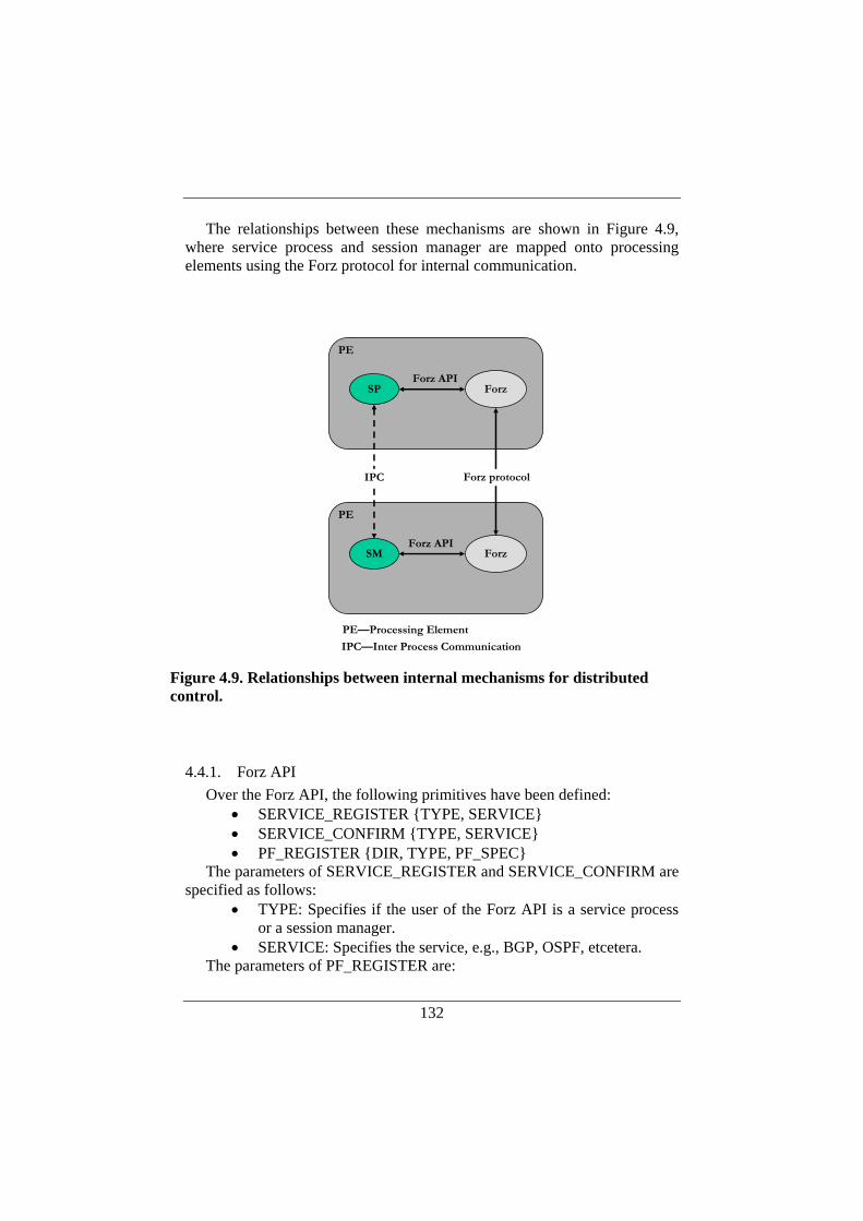
132
The relationships between these mechanisms are shown in Figure 4.9, where service process and session manager are mapped onto processing elements using the Forz protocol for internal communication.
4.4.1. Forz API Over the Forz API, the following primitives have been defined:
• SERVICE_REGISTER {TYPE, SERVICE} • SERVICE_CONFIRM {TYPE, SERVICE} • PF_REGISTER {DIR, TYPE, PF_SPEC}
The parameters of SERVICE_REGISTER and SERVICE_CONFIRM are specified as follows:
• TYPE: Specifies if the user of the Forz API is a service process or a session manager.
• SERVICE: Specifies the service, e.g., BGP, OSPF, etcetera. The parameters of PF_REGISTER are:
PE
SP Forz
PE
SM Forz
PE—Processing Element
Forz API
Forz protocolIPC
IPC—Inter Process Communication
Forz API
Figure 4.9. Relationships between internal mechanisms for distributed control.
133
• DIR: specifies if the filter concerns inbound or outbound traffic. • TYPE: specifies the type of filter, e.g., an IPv4 traffic filter. • PF_SPEC: is type-specific, e.g., the five-tuple consisting of
source address, destination address, source port, destination port, and protocol for an IPv4 filter.
Typically, both service processes and session managers will register their capabilities using the SERVICE_REGISTER primitives. Furthermore, the session manager will register a packet filter specifying the packets it wishes to receive for further processing. The session manager can be used for the processing of incoming messages for a specific service, outgoing messages for a specific service, or both.
The primitives described above translate into Forz protocol messages exchanged between processing elements in the distributed router. Capabilities learned through the SERVICE_REGISTER primitive are communicated through Forz HELLO messages during the Forz association part, earlier described in Chapter 2 (Section 2.5.1). The information distributed in this fashion can be used for basic configuration of packet redirect. However, we believe that the modularization and decentralization of the control plane calls for an extended and more flexible way to deal with packet redirect inside the NE. Therefore, we have decoupled this functionality from the communication of capabilities and introduced a separate Forz message for packet redirect information. We refer to this message as a Forz PF_REGISTER protocol message. Upon registration of a packet filter from a session manager, the Forz protocol will distribute this information to all participants within the NE. Accordingly, all FEs and CEs can use the information to filter out packets to be forwarded to the session manager for further processing.
4.4.2. Service-specific Inter-process Communication The required inter-process communication between service processes and
session managers depends on the actual service that is modularized and decentralized. The information that is exchanged between the different modules may include association and maintenance between service processes and session managers forming the service as a whole as well as the exchange of service specific information for workload distribution and failover methods.
When it comes to association and maintenance between modules, the inter-process communication depends on the level of dynamicity that is targeted. The internal relationship between session managers and service processes can either be configured or it can be established in a dynamic fashion where the different modules find each other automatically. Such a

134
dynamic association and maintenance can be based either on the mechanisms supported by the Forz protocols or by a service-specific protocol. As described earlier, the Forz protocols include support for dynamic association between processing elements, including heartbeat functionality. These mechanisms can be used by service processes and session managers.
The session manager side of the service is responsible for distributing the workload over service processes and it must thus be possible for the session manager to communicate a workload specification to the service processes. Moreover, the workload specification comes with a notification whether a service process should operate in active or passive mode regarding a specific share of the workload.
Inter-process communication between service processes and session managers is further discussed when we describe a modular and decentralized BGP implementation in Section 4.5.
4.4.3. Service Configuration As is the case with any routing protocol or other service provided by a
regular router, the distributed service implemented with service processes and session managers, according to the above, is subject to manual configurations. Even though the configuration is service-specific, some general guidelines should be considered. First, the level of configuration needed for the session manager should be kept to a minimum and the general design rule should be to keep the session manager as simple as possible. Advanced service-specific configuration, like e.g., BGP policies, should be done at the service process level and not at the session manager level. The main reason for this is that the decoupling of session manager from service processes is primarily thought of as a way to protect the system against crashing service processes. In particular, the design supports the failover from a broken service process to a working service process without affecting the remote peer. Even though session manager failover can be realized, it is more likely that a session manager failover may accidentally be exposed to remote peers for the particular service.
Still, a certain level of configuration regarding the session manager is likely to be inevitable. Examples of such configuration are information about external peers, expected number of internal service process, initial workload distribution between service process, and failover methods from active to passive service processes.
In addition, it is assumed that configuration information is distributed to service processes and session managers by a higher-level mechanism. The distribution of configuration information is outside the scope of this work.
135
4.4.4. Session Manager Implementation Aspects An interesting aspect with the session manager is the choice of transport
protocol used by the service. OSPF uses IP directly for communication between peers and that may simplify the design and implementation of the session manager. BGP, on the other hand, uses the transport service provided by TCP for its sessions with peers. A session manager for TCP-based session must be designed with care considering that the end-points using TCP assumes a reliable connections. If a remote external BGP peer sends a BGP message over TCP it assumes that there is a reliable connection all the way to the service process. This must not be jeopardized by the fact that the session has been split through the use of a session manager acting as a proxy.
The session manager may handle several internal processes participating in a session with one external peer. If large amounts of data are flowing from the external peer to the service processes it may be necessary to buffer data temporarily in the session manager. Alternatively, the session manager must make sure that the sending speed of the external peer is adapted to the slowest of the internal service processes.
Application data being relayed by the session manager must not be lost inside the session manager without appropriate actions being taken. For instance, if a session manager goes down and the TCP connections are migrated over to a backup session manager it must be detected if any application data is lost during this migration. If so, the session should be terminated and reactivated to make sure that the remote end is informed of the problem.
4.5. Decomposing BGP in a Distributed Control Plane In this section we describe our design and implementation of a modular
and decentralized BGP.
4.5.1. Traditional BGP Implementation A traditional BGP implementation runs on a single CPU that executes the
complete router control plane in a centralized monolithic fashion. The BGP implementation consists of several different parts: BGP neighbor negotiation, RIB-Ins (Routing Information Base constructed from incoming UPDATEs), RIB-Outs (Routing Information Base containing routes to be advertised to BGP peers), Loc-RIB (the routing table that the actual forwarding table is constructed from), in-policies, out-policies, and a decision process. The decision process operates on routes that exist in the RIB-Ins and is responsible for selecting which routes should be placed in the Loc-RIB as well as for selecting routes to be advertised to other BGP peers.

136
Neighbor negotiation proceeds according to a finite state machine (FSM) [41], and BGP maintains a separate FSM for each configured peer.
The BGP FSM is illustrated in Figure 4.10, and deals with the
establishment of a TCP connection for the BGP session and with the initial exchange of BGP messages that is needed to reach the final state, referred to as the “Established” state. When the FSM is in the “Established” state, the two peers can start exchanging UPDATE messages.
BGP UPDATE messages form the heart of the BGP protocol and these are the messages that are used to advertise routes in BGP. A route is an IP address prefix encoded in a <length, prefix> format, where the length field specifies the number of bits of the IP address prefix.
OpenConfirm
Established
OpenSent
Active Connect
Idle
OPENOPEN
NOTIFICATION
NOTIFICATION
NOTIFICATION
KEEPALIVE
KEEPALIVE
KEEPALIVEUPDATE
NOTIFICATION
BGP messages above are outgoing messages sent to the peer
[Source: S. Halabi, Cisco Systems]
Figure 4.10. Illustration of the BGP finite state machine.

137
4.5.2. BGP Modularization and Decentralization One of the main purposes with modularizing BGP is to spread the
computational work of BGP over several processing elements. Meanwhile, the modularized BGP should appear as a regular monolithic process to its external peers, maintaining one TCP connection to each BGP peer for the corresponding BGP session.
To achieve this, two main steps have been taken. First, we decouple the BGP FSM from the rest of the BGP software and let the FSM be executed by our session manager. Thus the session manager will be responsible for managing BGP sessions with external BGP peers.
In this way the decision process, including the databases (RIBs), can be separated from the actual BGP sessions. Second, we split the decision process into multiple distributed decision processes. Together, one of the distributed decision processes and its related databases form a service process.
Figure 4.11 illustrates how BGP is separated into session managers and service processes.
SessionManager 1
SessionManager 2
SessionManager N
RIB-Out NRIB-Out 2
RIB-In NRIB-In 2
RIB-Out 1
DecisionProcess Loc-RIB
RIB-In 1
ServiceProcess 1
RIB-Out NRIB-Out 2
RIB-In NRIB-In 2
RIB-Out 1
DecisionProcess Loc-RIB
RIB-In 1
ServiceProcess 2
RIB-Out NRIB-Out 2
RIB-In NRIB-In 2
RIB-Out 1
DecisionProcess Loc-RIB
RIB-In 1
ServiceProcess M
Figure 4.11. N Session managers connected to M service processes.
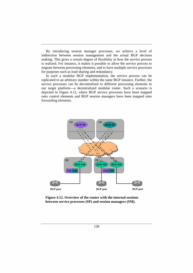
138
By introducing session manager processes, we achieve a level of indirection between session management and the actual BGP decision making. This gives a certain degree of flexibility in how the service process is realized. For instance, it makes it possible to allow the service process to migrate between processing elements, and to have multiple service processes for purposes such as load sharing and redundancy.
In such a modular BGP implementation, the service process can be replicated to an arbitrary number within the same BGP instance. Further, the service processes can be decentralized to different processing elements in our target platform—a decentralized modular router. Such a scenario is depicted in Figure 4.12, where BGP service processes have been mapped onto control elements and BGP session managers have been mapped onto forwarding elements.
BGP-SM
BGP-SPCE
BGP-SM BGP-SM
BGP-SPCE
FE FE
BGP peer BGP peer BGP peer
FIB FIBFIB FIB
Figure 4.12. Overview of the router with the internal sessions between service processes (SP) and session managers (SM).
139
As shown in the figure, we use multiple BGP session managers—typically one BGP session manager per external peer. However, session manager failover, as described in Section 4.3.3, has not been implemented in the current version of a distributed BGP implementation.
4.5.3. Initialization and Internal Communication For each configured BGP peer, the session manager maintains one TCP
connection for the BGP session with the peer and one internal TCP connection to each of the service processes. Thus, the session manager relays BGP messages between the external peers and the internal service processes.
As mentioned earlier, BGP specifies four different messages: OPEN, KEEPALIVE, NOTIFICATION, and UPDATE. OPEN and KEEPALIVE message are dealt with solely by the session manager in our approach to a decentralized and modular BGP. NOTIFICATION messages are sent as a result of a detected error, and may be generated by either the session manager or a service process, depending on the type of error. Outgoing UPDATE messages are always generated by a service process and relayed to the remote peer by the session manager. Incoming UPDATE messages are always relayed by the session manager to a service process.
According to the BGP specification, UPDATEs can be exchanged only when the BGP FSM is in the Established state. The BGP FSM is maintained entirely within the session manager, but it will not start until at least one service process is detected internally. When the BGP FSM for a BGP neighbor reaches the “Established” state, the session manager will notify the service processes that participate in the distributed BGP implementation. Thereafter, the service processes can receive and generate UPDATEs.
Each service process has one internal TCP connection for each configured peer. A service process maintains a very simple state machine compared to the BGP FSM. The basic principle for the service process is as follows: For each configured BGP peer it establishes an internal TCP connection to the corresponding session manager and creates an SP-FSM. (Service Process Finite State Machine) that goes into an idle state. The SP-FSM remains in an idle state until it gets notified by the session manager that the corresponding BGP FSM has entered the “Established” state. The SP-FSM then enters an active state where it can generate and receive UPDATEs. Along with the notification, the session manager can communicate workload specifications to the service processes. A workload specification is a range of IP address prefixes for which a certain service process is responsible. The session manager also informs whether a service process should act as primary or secondary for a specific IP address prefix range. Finally, information about the peer that the session manager learned
140
during execution of the BGP FSM can be communicated to the service processes at this point.
4.5.4. Robustness and Performance Aspects We claim that the decentralized modular design described here improves
performance as well as robustness. Performance gains can be made by sharing the total amount of computational work so that each service process handles a part of the total routing table. BGP lends itself to parallelization in a natural way. For instance, 8-bit IP address prefix blocks are independent of each other and messages can be dispatched over multiple service processes based on prefix block belongings. Then, various strategies for assigning such address prefix blocks to service processes can be applied to obtain load sharing. Such assignment strategies are further described and evaluated in the following section (Section 4.6). Under normal operation, the rate at which route updates arrive at a router is very modest. However, during short periods of time the processing load for the BGP decision process can temporarily be very high. This happens for instance at start-up and when there are sudden changes in the routing topology (due to route flaps, for example). We think that the difficulties related to processing these infrequent, sudden bursts of routing updates can be efficiently dealt with in a distributed router architecture that allows for load-sharing of the route update processing.
Separating session management from the service process (and thus from the BGP decision process) can potentially improve routing robustness. BGP decision making is a complex operation, where decision criteria are frequently changed, and the software that performs the decisions is often upgraded and/or modified. Session management, on the other hand, is in comparison a simple task where the requirements remain relatively stable. So assuming that the service process is more prone to software failures than session management, we gain the advantage of being able to keep sessions up even if there are faults in the service process.
The penalties for restarting BGP sessions come from the overhead involved in re-initiating the BGP peering states, and from the loss of connectivity at the packet forwarding level. However, using the graceful restart mechanisms for BGP [100], it would be possible to restart old sessions without loss of forwarding connectivity. A disadvantage with graceful restart is that there is no distinction between routing failures and link failures: In the case of link failures, the peers will continue to forward packets over the failed links, which is not the desired behavior. One of the advantages of separating session management from the decision process is that it makes it possible to distinguish "true" link failures through the loss of
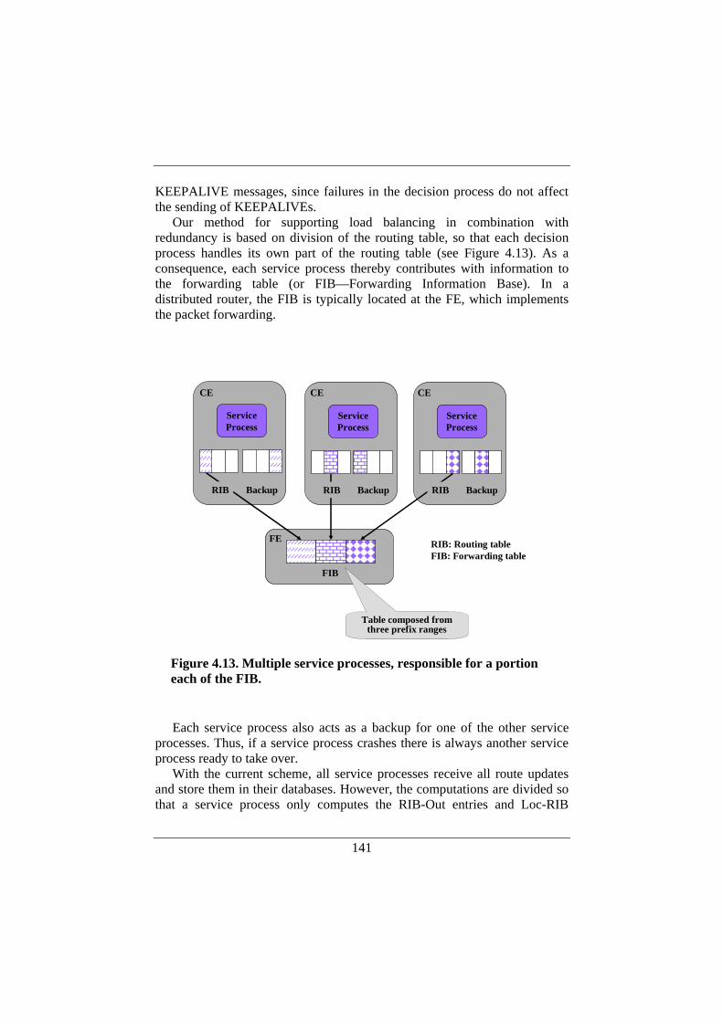
141
KEEPALIVE messages, since failures in the decision process do not affect the sending of KEEPALIVEs.
Our method for supporting load balancing in combination with redundancy is based on division of the routing table, so that each decision process handles its own part of the routing table (see Figure 4.13). As a consequence, each service process thereby contributes with information to the forwarding table (or FIB—Forwarding Information Base). In a distributed router, the FIB is typically located at the FE, which implements the packet forwarding.
Each service process also acts as a backup for one of the other service
processes. Thus, if a service process crashes there is always another service process ready to take over.
With the current scheme, all service processes receive all route updates and store them in their databases. However, the computations are divided so that a service process only computes the RIB-Out entries and Loc-RIB
ServiceProcess
ServiceProcess
FIB
Backup BackupRIB RIB
ServiceProcess
BackupRIB
FE
CE CE CE
RIB: Routing tableFIB: Forwarding table
Table composed from three prefix ranges
Figure 4.13. Multiple service processes, responsible for a portion each of the FIB.
142
entries that fall within that service process’ part of the routing table (this is further described in Section 4.6). The idea here is to make sure that service processes have all information available in their databases, so that they quickly can take over should other service processes fail. The amount of computations that each service process needs to perform is reduced, since a service process only deals with a smaller part of the routing table. An alternative scheme would be to let the session manager perform filtering of BGP UPDATEs so that each service process only receives the BGP UPDATEs that are within its responsibility. That would somewhat decrease the amount of burden on the service processes and also the load on the internal network. On the other hand, the information would not be locally available in the service process in a fail-over scenario.
In addition, filtering BGP UPDATEs in the session manager is somewhat a delicate issue. A BGP UPDATE received from an external peer can contain several routes according to the <length, prefix> format described earlier. Moreover, it may contain both withdrawn routes and new routes. Different routes may belong to different 8-bit prefix blocks and thus the information in one UPDATE may have to split between several service processes. Therefore, filtering UPDATEs in the session manager means that the session manager must split the external UPDATE message into several internal UPDATE messages where one internal UPDATE message contains only routes within the prefix block assigned to a particular service process.
4.6. Performance Evaluation of a Distributed BGP In this section, we have applied our ideas on control plane modularization
and decentralization to BGP [95], to investigate the hypothesis regarding improved control plane performance under heavy load. The primary purpose with this work is to carry out an experimental evaluation of control plane performance using distributed processing. Our approach to make BGP performance improvements is to spread the BGP workload over multiple processing elements so that each element is responsible for a part of the complete routing table. The idea is to reduce the amount of computations that each processing element has to perform since it deals only with a subset of the routing table. Making such a load sharing efficient requires an understanding of how real BGP load affects the computational workload related to BGP processing. The focus is on the processing of BGP UPDATE messages and installation of routes in the routing table. To gain understanding of how the computation of the routing table could be shared between processing elements it is of interest to find out what BGP load looks like. This includes characteristics like number of routes, distribution of
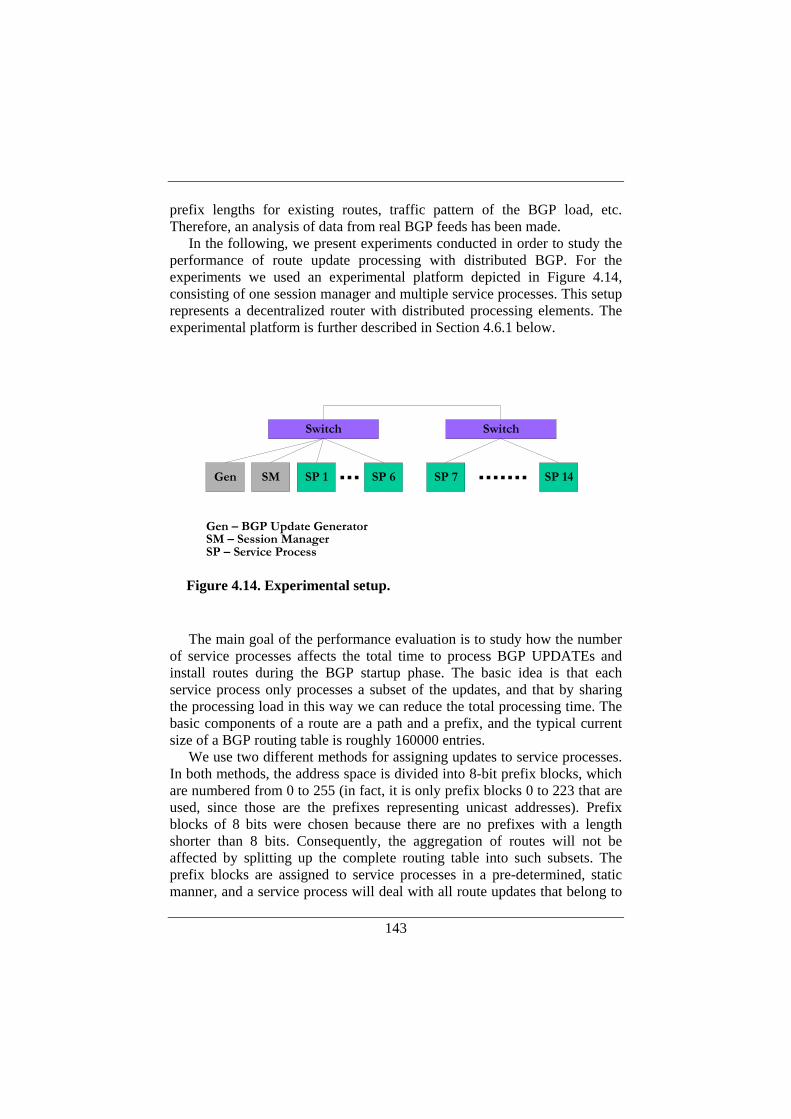
143
prefix lengths for existing routes, traffic pattern of the BGP load, etc. Therefore, an analysis of data from real BGP feeds has been made.
In the following, we present experiments conducted in order to study the performance of route update processing with distributed BGP. For the experiments we used an experimental platform depicted in Figure 4.14, consisting of one session manager and multiple service processes. This setup represents a decentralized router with distributed processing elements. The experimental platform is further described in Section 4.6.1 below.
The main goal of the performance evaluation is to study how the number
of service processes affects the total time to process BGP UPDATEs and install routes during the BGP startup phase. The basic idea is that each service process only processes a subset of the updates, and that by sharing the processing load in this way we can reduce the total processing time. The basic components of a route are a path and a prefix, and the typical current size of a BGP routing table is roughly 160000 entries.
We use two different methods for assigning updates to service processes. In both methods, the address space is divided into 8-bit prefix blocks, which are numbered from 0 to 255 (in fact, it is only prefix blocks 0 to 223 that are used, since those are the prefixes representing unicast addresses). Prefix blocks of 8 bits were chosen because there are no prefixes with a length shorter than 8 bits. Consequently, the aggregation of routes will not be affected by splitting up the complete routing table into such subsets. The prefix blocks are assigned to service processes in a pre-determined, static manner, and a service process will deal with all route updates that belong to
SP 6Gen SP 1 SP 7 SP 14
Switch Switch
SM
Gen – BGP Update GeneratorSM – Session ManagerSP – Service Process
Figure 4.14. Experimental setup.
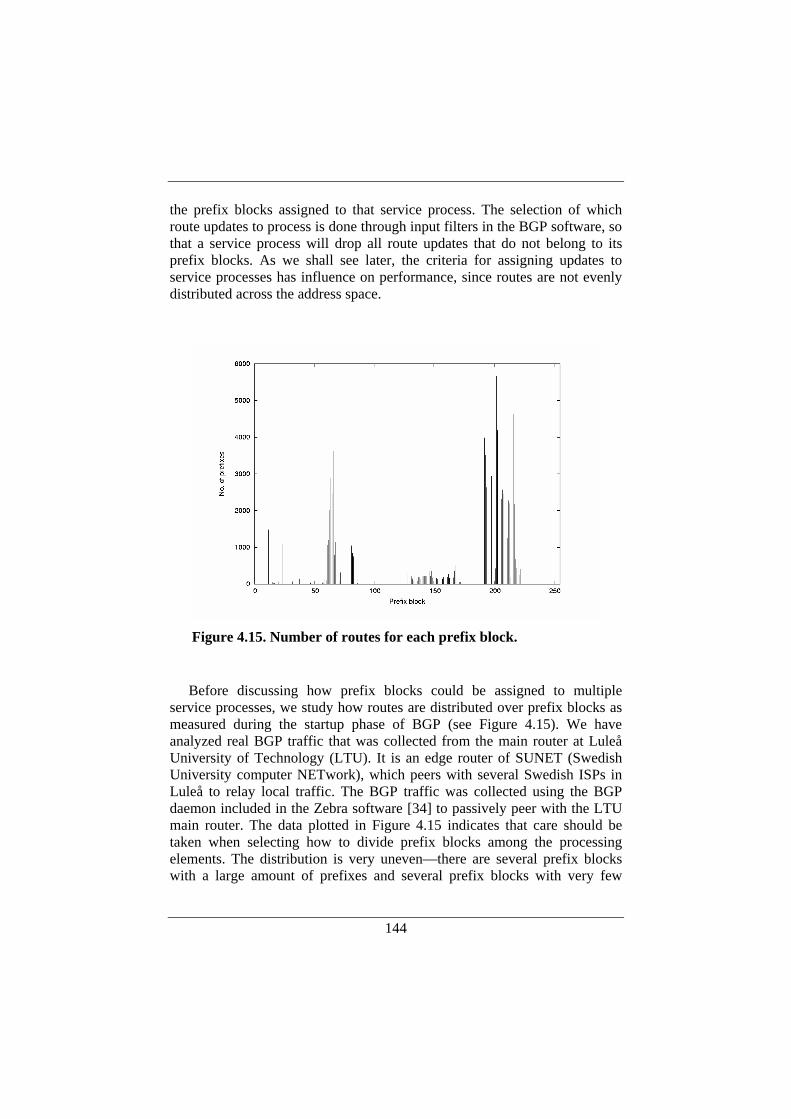
144
the prefix blocks assigned to that service process. The selection of which route updates to process is done through input filters in the BGP software, so that a service process will drop all route updates that do not belong to its prefix blocks. As we shall see later, the criteria for assigning updates to service processes has influence on performance, since routes are not evenly distributed across the address space.
Before discussing how prefix blocks could be assigned to multiple
service processes, we study how routes are distributed over prefix blocks as measured during the startup phase of BGP (see Figure 4.15). We have analyzed real BGP traffic that was collected from the main router at Luleå University of Technology (LTU). It is an edge router of SUNET (Swedish University computer NETwork), which peers with several Swedish ISPs in Luleå to relay local traffic. The BGP traffic was collected using the BGP daemon included in the Zebra software [34] to passively peer with the LTU main router. The data plotted in Figure 4.15 indicates that care should be taken when selecting how to divide prefix blocks among the processing elements. The distribution is very uneven—there are several prefix blocks with a large amount of prefixes and several prefix blocks with very few
Figure 4.15. Number of routes for each prefix block.
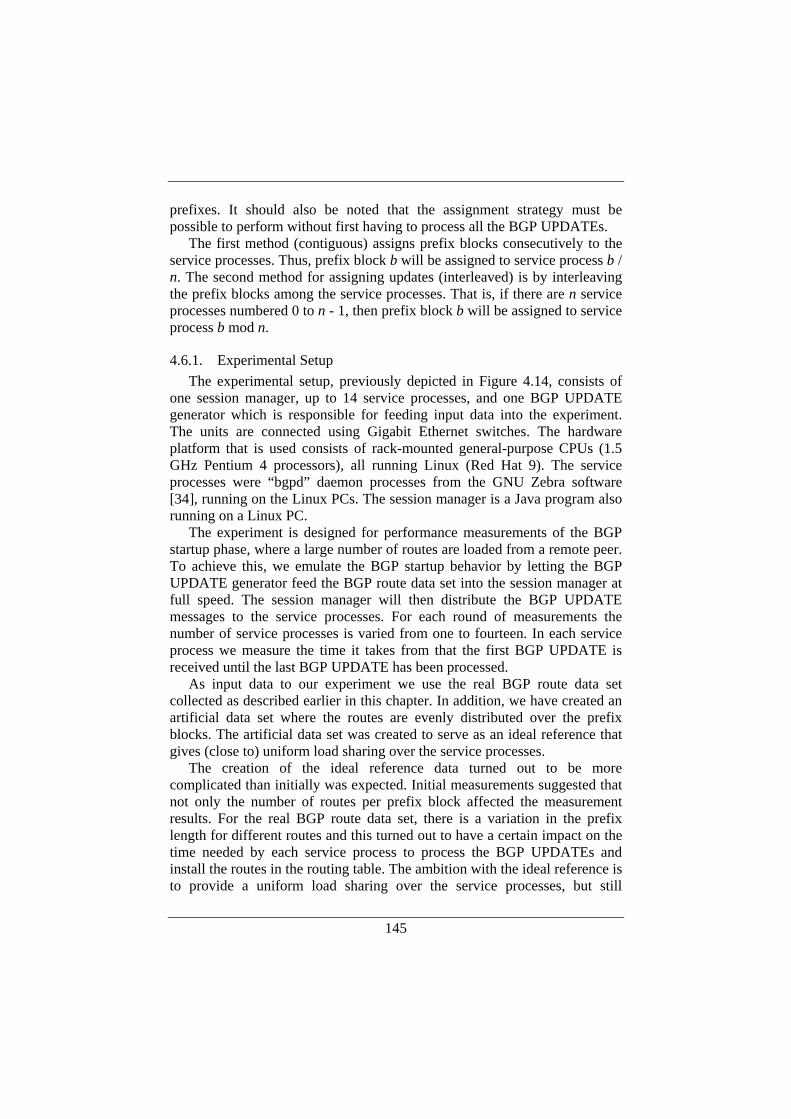
145
prefixes. It should also be noted that the assignment strategy must be possible to perform without first having to process all the BGP UPDATEs.
The first method (contiguous) assigns prefix blocks consecutively to the service processes. Thus, prefix block b will be assigned to service process b / n. The second method for assigning updates (interleaved) is by interleaving the prefix blocks among the service processes. That is, if there are n service processes numbered 0 to n - 1, then prefix block b will be assigned to service process b mod n.
4.6.1. Experimental Setup The experimental setup, previously depicted in Figure 4.14, consists of
one session manager, up to 14 service processes, and one BGP UPDATE generator which is responsible for feeding input data into the experiment. The units are connected using Gigabit Ethernet switches. The hardware platform that is used consists of rack-mounted general-purpose CPUs (1.5 GHz Pentium 4 processors), all running Linux (Red Hat 9). The service processes were “bgpd” daemon processes from the GNU Zebra software [34], running on the Linux PCs. The session manager is a Java program also running on a Linux PC.
The experiment is designed for performance measurements of the BGP startup phase, where a large number of routes are loaded from a remote peer. To achieve this, we emulate the BGP startup behavior by letting the BGP UPDATE generator feed the BGP route data set into the session manager at full speed. The session manager will then distribute the BGP UPDATE messages to the service processes. For each round of measurements the number of service processes is varied from one to fourteen. In each service process we measure the time it takes from that the first BGP UPDATE is received until the last BGP UPDATE has been processed.
As input data to our experiment we use the real BGP route data set collected as described earlier in this chapter. In addition, we have created an artificial data set where the routes are evenly distributed over the prefix blocks. The artificial data set was created to serve as an ideal reference that gives (close to) uniform load sharing over the service processes.
The creation of the ideal reference data turned out to be more complicated than initially was expected. Initial measurements suggested that not only the number of routes per prefix block affected the measurement results. For the real BGP route data set, there is a variation in the prefix length for different routes and this turned out to have a certain impact on the time needed by each service process to process the BGP UPDATEs and install the routes in the routing table. The ambition with the ideal reference is to provide a uniform load sharing over the service processes, but still
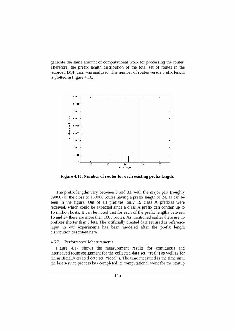
146
generate the same amount of computational work for processing the routes. Therefore, the prefix length distribution of the total set of routes in the recorded BGP data was analyzed. The number of routes versus prefix length is plotted in Figure 4.16.
The prefix lengths vary between 8 and 32, with the major part (roughly
89000) of the close to 160000 routes having a prefix length of 24, as can be seen in the figure. Out of all prefixes, only 19 class A prefixes were received, which could be expected since a class A prefix can contain up to 16 million hosts. It can be noted that for each of the prefix lengths between 16 and 24 there are more than 1000 routes. As mentioned earlier there are no prefixes shorter than 8 bits. The artificially created data set used as reference input in our experiments has been modeled after the prefix length distribution described here.
4.6.2. Performance Measurements Figure 4.17 shows the measurement results for contiguous and
interleaved route assignment for the collected data set (“real”) as well as for the artificially created data set (“ideal”). The time measured is the time until the last service process has completed its computational work for the startup
Figure 4.16. Number of routes for each existing prefix length.
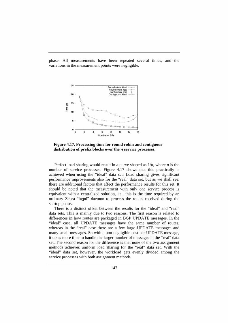
147
phase. All measurements have been repeated several times, and the variations in the measurement points were negligible.
Perfect load sharing would result in a curve shaped as 1/n, where n is the
number of service processes. Figure 4.17 shows that this practically is achieved when using the “ideal” data set. Load sharing gives significant performance improvements also for the “real” data set, but as we shall see, there are additional factors that affect the performance results for this set. It should be noted that the measurement with only one service process is equivalent with a centralized solution, i.e., this is the time required by an ordinary Zebra “bgpd” daemon to process the routes received during the startup phase.
There is a distinct offset between the results for the “ideal” and “real” data sets. This is mainly due to two reasons. The first reason is related to differences in how routes are packaged in BGP UPDATE messages. In the “ideal” case, all UPDATE messages have the same number of routes, whereas in the “real” case there are a few large UPDATE messages and many small messages. So with a non-negligible cost per UPDATE message, it takes more time to handle the larger number of messages in the “real” data set. The second reason for the difference is that none of the two assignment methods achieves uniform load sharing for the “real” data set. With the “ideal” data set, however, the workload gets evenly divided among the service processes with both assignment methods.
Figure 4.17. Processing time for round robin and contiguous distribution of prefix blocks over the n service processes.
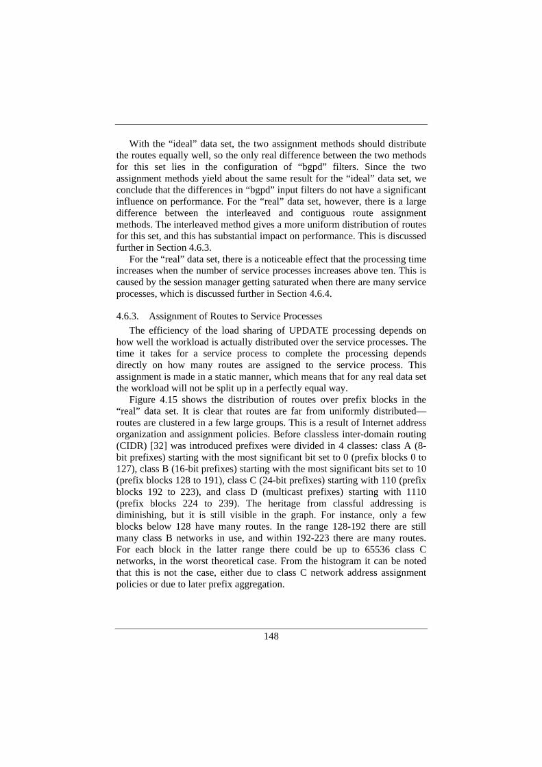
148
With the “ideal” data set, the two assignment methods should distribute the routes equally well, so the only real difference between the two methods for this set lies in the configuration of “bgpd” filters. Since the two assignment methods yield about the same result for the “ideal” data set, we conclude that the differences in “bgpd” input filters do not have a significant influence on performance. For the “real” data set, however, there is a large difference between the interleaved and contiguous route assignment methods. The interleaved method gives a more uniform distribution of routes for this set, and this has substantial impact on performance. This is discussed further in Section 4.6.3.
For the “real” data set, there is a noticeable effect that the processing time increases when the number of service processes increases above ten. This is caused by the session manager getting saturated when there are many service processes, which is discussed further in Section 4.6.4.
4.6.3. Assignment of Routes to Service Processes The efficiency of the load sharing of UPDATE processing depends on
how well the workload is actually distributed over the service processes. The time it takes for a service process to complete the processing depends directly on how many routes are assigned to the service process. This assignment is made in a static manner, which means that for any real data set the workload will not be split up in a perfectly equal way.
Figure 4.15 shows the distribution of routes over prefix blocks in the “real” data set. It is clear that routes are far from uniformly distributed—routes are clustered in a few large groups. This is a result of Internet address organization and assignment policies. Before classless inter-domain routing (CIDR) [32] was introduced prefixes were divided in 4 classes: class A (8-bit prefixes) starting with the most significant bit set to 0 (prefix blocks 0 to 127), class B (16-bit prefixes) starting with the most significant bits set to 10 (prefix blocks 128 to 191), class C (24-bit prefixes) starting with 110 (prefix blocks 192 to 223), and class D (multicast prefixes) starting with 1110 (prefix blocks 224 to 239). The heritage from classful addressing is diminishing, but it is still visible in the graph. For instance, only a few blocks below 128 have many routes. In the range 128-192 there are still many class B networks in use, and within 192-223 there are many routes. For each block in the latter range there could be up to 65536 class C networks, in the worst theoretical case. From the histogram it can be noted that this is not the case, either due to class C network address assignment policies or due to later prefix aggregation.
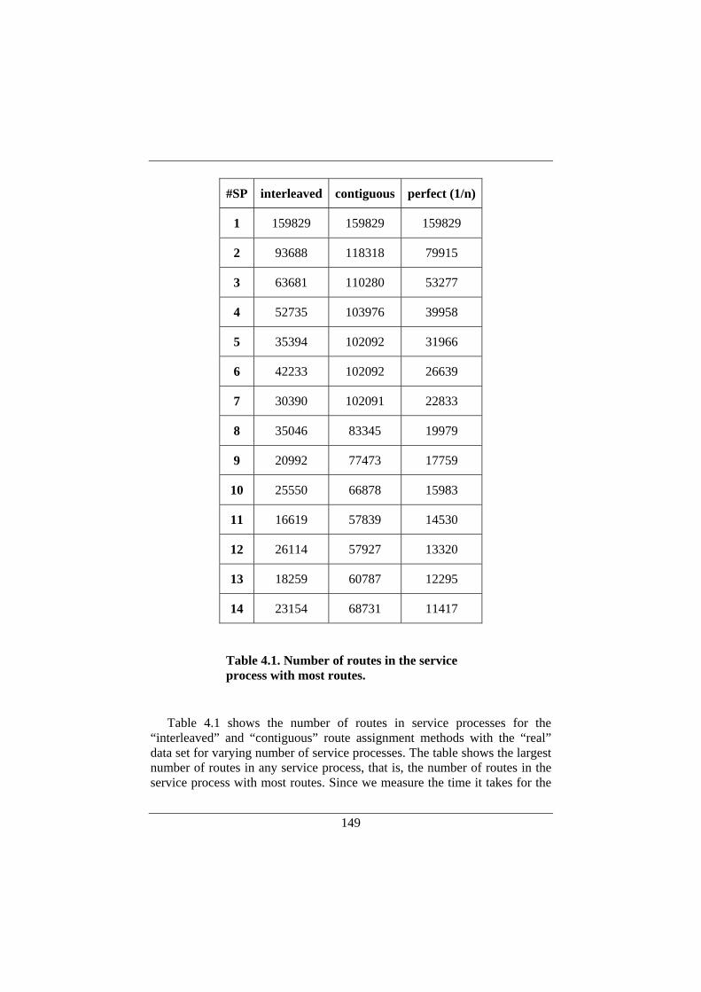
149
Table 4.1 shows the number of routes in service processes for the
“interleaved” and “contiguous” route assignment methods with the “real” data set for varying number of service processes. The table shows the largest number of routes in any service process, that is, the number of routes in the service process with most routes. Since we measure the time it takes for the
#SP interleaved contiguous perfect (1/n)
1 159829 159829 159829
2 93688 118318 79915
3 63681 110280 53277
4 52735 103976 39958
5 35394 102092 31966
6 42233 102092 26639
7 30390 102091 22833
8 35046 83345 19979
9 20992 77473 17759
10 25550 66878 15983
11 16619 57839 14530
12 26114 57927 13320
13 18259 60787 12295
14 23154 68731 11417
Table 4.1. Number of routes in the service process with most routes.
150
last service process to finish, which (in all our measurements) is the process with the most routes, the largest number of routes in a service process determines the overall performance. The table shows that the largest number of routes is in general significantly higher with the contiguous method, which explains why it takes longer time to process UPDATE messages with this method. Furthermore, it can also be seen that for both assignments methods, the largest number of routes does not decrease strictly with increasing number of service processes, which is also visible from the irregularities of the two curves for the “real” data set in Figure 4.17 (at the data points for 4 to 6 service processes, for example).
4.6.4. UPDATE Message Size UPDATE messages may contain a variable number of routes. Since there
is a certain per message cost—the cost associated with transmitting a message independent of its size—it is in general more efficient to send fewer, large messages compared to many small. This is true also for our experimental system, as can be seen in Figure 4.18.
The figure shows the time it takes to assign the routes to the service
processes versus the number of service processes. The measurements were performed using BGP UPDATE messages containing 1, 5 and 20 routes respectively. In this experiment we are interested in the performance of the
Figure 4.18. Time to distribute routes to service processes for different UPDATE message sizes versus number of service processes.
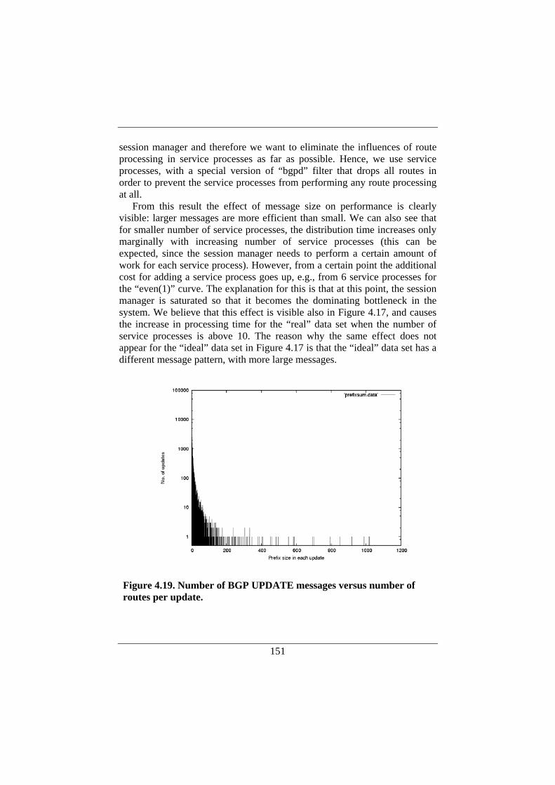
151
session manager and therefore we want to eliminate the influences of route processing in service processes as far as possible. Hence, we use service processes, with a special version of “bgpd” filter that drops all routes in order to prevent the service processes from performing any route processing at all.
From this result the effect of message size on performance is clearly visible: larger messages are more efficient than small. We can also see that for smaller number of service processes, the distribution time increases only marginally with increasing number of service processes (this can be expected, since the session manager needs to perform a certain amount of work for each service process). However, from a certain point the additional cost for adding a service process goes up, e.g., from 6 service processes for the “even(1)” curve. The explanation for this is that at this point, the session manager is saturated so that it becomes the dominating bottleneck in the system. We believe that this effect is visible also in Figure 4.17, and causes the increase in processing time for the “real” data set when the number of service processes is above 10. The reason why the same effect does not appear for the “ideal” data set in Figure 4.17 is that the “ideal” data set has a different message pattern, with more large messages.
Figure 4.19. Number of BGP UPDATE messages versus number of routes per update.
152
It can be seen from Figure 4.18 that with larger messages, this effect has
smaller influence and occurs for a higher number of service processes. For the specific data set used in our experiments, the number of routes
per BGP UPDATE varies between 1 and 1020, which can be seen in Figure 4.19. There are 30872 updates that are within the recorded startup sequence. It can be noted that approximately half of the BGP UPDATEs contains only one route, while the other half contains from 2 up to 1020 prefixes in each update. However, the total number of BGP UPDATEs and the number of routes per BGP UPDATE during the startup sequence are parameters that are likely to differ between various BGP routers in the Internet.
4.6.5. Discussion The experiments indicate that there are significant performance gains to
be made by utilizing the parallelism through a distributed implementation of BGP UPDATE processing. The distribution of the workload, in terms of number of routes, has large impact on performance. The two simple, static methods that we use differ in this respect. The “contiguous” method gives a very unbalanced distribution of the workload for the “real” data set. The “interleaved” method is better, but far from perfect.
It would be possible to devise a more elaborate scheme for workload distribution, for example by analyzing routes and computing a route filter configuration that gives a good distribution for a particular set or routes. Such a method would depend on the assumption that route distributions over prefixes do not change rapidly over time, which appear to be reasonable. However, there is a certain trade-off with this approach. A filter configuration that gives optimal workload may turn out to be very specific, and could consist of many filters. In that case the filter processing in the service processes may occupy the resources to an extent where filter processing dominates the processing time in the service processes. So a more sophisticated approach would need to balance filter processing against route processing in the service processes.
The session manager influences performance when the number of service processes gets large. There is certainly room for improvements of the session manager as well, for instance by exploring parallelism, using multicast for distribution of UPDATE messages, etc. In our measurements, the session manager becomes a limiting factor when the number of service processes gets relatively large. At this point, the theoretical additional gain of adding one more service process is lower, so it is unclear whether an optimization of the session manager can be justified in terms of the additional performance that could be gained. However, there are situations where a session manager
153
could potentially benefit from hardware support. For instance, if BGP session authentication is used, the authenticity of each BGP message received needs to be cryptographically verified before it can be passed to the service processes. This is a processing intensive operation, so if the session manager can be implemented on specialized hardware (on a network processor for example), it would be a way to significantly improve the performance of a session manager. Hardware support for session managers has significance also from a robustness point of view. Potential denial of service (DoS) attacks against BGP routers involve sending large amounts of packets that could potentially lock up the entire BGP packet processing resources in the router (such as messages that require authentication). By spreading out session management processing over multiple processing elements which are optimized for packet processing, the router will be more robust against such attacks.
It should also be noted that improved BPG processing performance through replication and load sharing among service processes can implicitly improve dependability in a more general sense. For instance, there are situations when the router control plane is heavily loaded with control traffic. Some examples are during topology changes and route flaps where routing computations potentially may lock up the router. The distributed BGP computation presented here can be seen as a way to reduce the vulnerability of the control plane.
The BGP processing should also be put in perspective to local forwarding table updates in the forwarding plane. It could be argued that forwarding table updates constitute the bottleneck rather than the BGP processing in the control plane. However, as mentioned earlier (in Section 3.6.1), the update time depends heavily on the actual implementation of the forwarding table. It was also noted that hardware-based forwarding tables can support up to 100,000 table updates per second.
The BGP processing times we have measured include updating the local RIB in the control plane, and the shortest time we have reached in our measurements is around 5 seconds for roughly 160,000 updates. In other words, we have been able to achieve BGP processing times that are in the same order of magnitude as the FIB update times for sophisticated hardware implementations. These results are encouraging, since with a centralized design the corresponding BGP processing would clearly be an overall performance bottleneck when a large number of routes are loaded from a remote peer during the startup phase. This can be seen in Figure 4.17, where the total processing time when using one service process is close to 20 seconds.
154
4.7. Conclusion and Further Work In this chapter, we have proposed a distributed control plane for
decentralized modular router architectures. The basis for the design is a modularization of the control plane, where control functions are partitioned into independent modules, referred to as service processes and session managers. These modules can then be distributed over a set of processing elements in the distributed router. The modularization can be used for functional separation, redundancy, and load balancing purposes. The main motivations for the partitioning into session managers and service processes are as follows. The session manager can be kept rather simple, and it is a way to conceal the internal distributed architecture so that modularization and decentralization can be accomplished without influencing the way in which the router communicates with its remote peers. The suggested decoupling of service process from session manager also allows the former to be replicated in a straight-forward fashion.
We have further demonstrated how the control plane of a router can be modularized and distributed over multiple processing units. We have examined how this design can be used to improve the performance of BGP route update processing. Our results indicate that UPDATE messages are cumbersome to process, and by distributing the workload over multiple units, the processing time can be significantly reduced. This is particularly important for speeding up the processing of large amount of routing updates, which can occur for instance at router startup time, and during route flaps and other sudden changes in the topology.
We have performed experiments with real data sets that has been collected from a border router connected to SUNET; the Swedish university network. We have experimented with different approaches for distributing the workload over the processing units, and we have found that this has large impact on the overall performance. The optimal distribution of the workload is dependent on the structure of the routes, and for further work it would therefore be interesting to study route data sets from other routers on the Internet, and to investigate alternative methods for workload assignment.
We have dealt mainly with performance aspects of distributed UPDATE processing. However, the modularized and decentralized architecture opens up interesting possibilities also for using replication of critical functions as a means to improve router robustness. We believe that the design devised in this chapter provides a solid basis for increased robustness of router control functions through the use of redundant processing. As further work, it would be interesting to study aspects related to robustness and availability more closely, e.g., by exploring in detail how backup units and fail-over handling can be implemented on our platform and compared with fail-over
155
mechanisms in existing commercial routers, typically involving redundant CPU modules (i.e., the complete control plane) or even redundant routers.
Finally, we have demonstrated that distributed BGP processing does not require the BGP software to be completely redesigned and rewritten. It is possible to modularize existing implementations—we have used a more or less unmodified version of the GNU Zebra open source implementation of BGP for our experiments. To further investigate the flexibility of this approach it would be interesting to incorporate also other BGP implementations in the experiments. One obvious candidate worth exploring in terms of decentralization over multiple processing elements is the BGP implementation included in XORP [45].

156
157
5. CONCLUSIONS AND FURTHER WORK
In this thesis, we have explored modular and decentralized architectures for network systems in order to meet current and future requirements on IP routers. The main requirements that we have identified are related to scalability, flexibility, and robustness of IP routers. To address these requirements, we have proposed a distributed and modular approach to network system design, where the network system is composed of physically separated functional elements, which communicate over an internal network using an open well-defined communication protocol.
One of the outcomes of this thesis work is the prototype that has been developed and used for experiments regarding distributed network systems. This experimental platform is modular, which means that new software and/or hardware modules can be added to the system, hopefully with a limited amount of implementation work. One of our practical design goals has been to conform to a modular software architecture where generic code, protocol specific code, and platform specific code are kept separated in a layered fashion. Consequently, the design should allow for experimentation with new types of control plane software, functional elements, internal communication protocols, internal transport mechanisms, etc.
The research methodology for the thesis work has been based on design, implementation and experimental verification. Accordingly, we have presented system design and implementation work as well as experimental analysis of specific parts of the system throughout the thesis.
The starting point for the design work was the ForCES model [31], where control and forwarding functionality in network systems can be physically separated and distributed to multiple processing elements. Different design alternatives for both control elements and forwarding elements have been put forward and various implementation aspects have been elucidated. It has been demonstrated that a network system can be designed and implemented in a modular and distributed fashion. It has further been shown that such a system need not necessarily be built from scratch. Instead, we have proven that a traditional monolithic router, such as a PC-based router running a Unix operating system, can be modularized into components that are distributed over multiple processing elements communicating over an internal IP-based network. Specifically we have suggested a protocol—Forz—for internal communication. Forz is based on one of the original proposals for the ForCES protocol, which is the emerging standard for communication between control elements and forwarding elements.

158
The focus of the experimental work for this thesis has been on the internal network and internal transport mechanisms for distribution of relatively large amounts of data between control elements and forwarding elements. In particular, we have investigated various transport level mechanisms for the dissemination of large routing tables from a control element to a varying number of forwarding elements. The studies include the use of TCP, UDP, and protocols for reliable multicast. Specifically, we have evaluated NORM (NACK-Oriented Reliable Multicast) as a candidate transport level mechanism for routing table dissemination in distributed routers.
We have studied the communication overhead in terms of distribution times introduced by Forz and its associated transport mechanisms. We have also reported performance figures regarding the overall control plane operation performance in our distributed router when receivers in forms of forwarding elements must process routing information received from a control element and install the received routes in local forwarding tables.
Our results show that the sheer communication overhead of NORM is close to the one introduced by a hand-tuned “ideal” UDP-based transport mechanism. Furthermore, the distribution times turned out to be of the same order of magnitude as update times for advanced hardware-based routing tables. The results are promising, since they indicate that the communication overhead does not rule out the decentralized design.
However, when the experiments include receiver processing of data NORM results in a noticeable performance penalty compared to an ideal multicast transport based on UDP with rate control. Still, the performance decreased only modestly with the number of receivers in our experiments. Therefore, we conclude that from a scaling perspective NORM is superior to an alternative like using multiple TCP connections to achieve reliable multicast transport.
Furthermore, architectural as well as experimental work regarding the use of multiple processing elements in a distributed modular control plane design has been presented. The overall purpose with such an approach is to improve control plane robustness and performance. In this part of the thesis work we have identified internal mechanisms needed to provide the means for a distributed control plane. Moreover, a general design and implementation approach has been suggested, where control functions such as routing protocols can be divided into service processes and session managers. The service process implements the actual control function, while the session manager establishes and maintains communication with external peers. This approach has been applied to BGP and we have examined how such a distributed BGP design can be used to improve the performance of
159
BGP route update processing under heavy load. Our results indicate that the processing time can be significantly reduced by distributing the workload over multiple service processes running on separate processing elements.
Even though our ideas regarding control plane modularization have been implemented only for BGP so far, initial studies of other routing protocols indicate that they can be decomposed into several independent modules and mapped onto multiple processing elements. We therefore believe that the approach is useable for other routing protocols as well.
One example of future work that we believe is both timely and relevant is to replace the Forz protocol with the ForCES protocol that is currently close to becoming a new IETF standard. At the time when the thesis work began, no such protocol was available, but several different ideas were discussed. The Forz implementation was based on one of those ideas. We believe that in the near future there is a need for evaluating the performance and correctness of the ForCES protocol and also to study how to map ForCES onto different types of transport layers. Such experiments could preferably be made on the prototype system presented in this thesis.
Another matter that is suitable for further research relates to the design of the internal data network. Throughout this thesis work we have mainly dealt with the internal control network and communication of control information between control and forwarding elements. The requirements on the internal data network are significantly different. There is a need to devise innovative designs of high-performance internal data networks for the distributed architecture that has been put forward in this thesis. Possible experimental research in this area should also include specialized forwarding hardware with state-of-the-art performance.
We believe that the distributed control plane proposed in this thesis opens up for a large amount of future work. This includes both a continuation of the BGP-specific work as well as to apply our ideas on other control plane functions. When it comes to the distributed BGP presented here, the performance evaluation was based on rather simple schemes for workload distribution over multiple processing elements. Those served well as a proof of concept, but more sophisticated methods could be devised and evaluated experimentally. Further, the focus of the experimental work presented in the thesis has been on performance of the distributed control plane. A natural continuation would be to conduct experimental work also regarding service process failures and failover times.
The approach of dividing control functions into service processes and session managers has so far been applied in detail only on BGP. An interesting topic for further work would be to more closely study how the approach can be extended to other control plane functions.

160
As a final point, we believe that there is a gain in allowing components to evolve independently and that modularization may be a way to provide such a scenario. Such a modularization could, if it proves successful, have impact on the router industry. A modular and decentralized approach to building routers would ultimately open up for sub-system vendors to develop specific parts of a router and for system vendors to focus on integration of modules, choosing whatever modules may best fit their needs.
161
REFERENCES [1] R. B. Adamson, J. P. Macker, “Quantitative Prediction of NACK-
Oriented Reliable Multicast (NORM) Feedback”, Proceedings of MILCOM 2002, vol. 2, pp. 964-969, October 2002.
[2] B. Adamson et al, “Negative-acknowledgment (NACK)-Oriented Reliable Multicast (NORM) Protocol”, IETF Internet RFC 3940, November 2004.
[3] B. Adamson et al, “Negative-Acknowledgment (NACK)-Oriented Reliable Multicast (NORM) Building Blocks”, IETF Internet RFC 3941, November 2004.
[4] L. Alvisi, et. al., “Wrapping Server-Side TCP to Mask Connection Failures”, Proc. IEEE INFOCOM’01, Vol. 1, pp. 329-337, Anchorage, Alaska, USA, April 2001.
[5] S. Armstrong, A. Freier, K. Marzullo, “Multicast Transport Protocol”, IETF Internet RFC 1301, February 1992.
[6] J. Aweya, “IP Router Architectures: An Overview”, Journal of Systems Architecture 46, pp. 483-511, 1999.
[7] F. Baker, “Requirements for IP version 4 Routers”, IETF Internet RFC 1812, June 1995.
[8] M. P. Barcellos, “Reliable Multicast for the Grid: a comparison of protocol implementations”, e-Science All-Hands Meeting, Nottingham, UK, September 2004.
[9] A. Basu, C. L. Ong, A. Rasala, F. Shepherd, G. Wilfong, “Route Oscillation in I-BGP with Route Reflection”, in Proc. ACM SIGCOMM ’02, pp. 235-247, Pittsburgh, PA, USA, August 2002.
[10] A. Basu, J. G. Riecke, “Stability Issues in OSPF Routing”, in Proc. ACM SIGCOMM ’01, pp. 225-236, San Diego, CA, USA, August 2001.
[11] T. Bates, R. Chandra, and E. Chen, “BGP Route Reflection—An Alternative to Full Mesh IBGP”, IETF Internet RFC 2796, April 2000.
[12] A. Bianco, et al., “Click vs Linux: Two Efficient Open-Source IP Network Stacks for Software Routers”, in Proceedings of the 2005 IEEE Workshop on High Performance Switching and Routing (HPSR’05), Hong Kong, May 2005.
[13] J. W. Byers, M. Luby, M. Mitzenmacher, A. Rege, “A Digital Fountain Approach to Reliable Distribution of Bulk Data”, in Proc. ACM SIGCOMM ’98, pp. 56-67, Vancouver, B. C., Canada, August/September 1998.

162
[14] R. Callon, “Use of OSI IS-IS for Routing in TCP/IP and Dual Environments”, IETF Internet RFC 1195, December 1990.
[15] A. Chaintreau, F. Baccelli, and C. Diot, “Impact of Network Delay Variations on Multicast Sessions with TCP-like Congestion Control”, Proc. IEEE INFOCOM ’01, Vol. 2, pp 1133-1142, Anchorage, Alaska, April 2001.
[16] H. Chan, H. Alnuweiri, and V. Leung, “A framework for optimizing the cost and performance of next-generation IP routers”, IEEE JSAC, vol. 17, no. 6, pp1013-1029, June 1999.
[17] C-S. Chang, D. S. Lee, and Y. S. Jou, “Load Balanced Birkhoff-von Neumann Switches, part I: One-stage Buffering”, in Proceedings of the 2001 IEEE Workshop on High Performance Switching and Routing (HPSR’01), Dallas, May 2001.
[18] C-S. Chang, D. S. Lee, and C. M. Lien, “Load Balanced Birkhoff-von Neumann Switches, part II: Multi-stage Buffering”, Computer Comm., Vol. 25, pp. 623-634, 2002.
[19] D. Chang, R. Govindan, J. Heidemann, “An emperical Study of Router Response to Large BGP Routing Table Load”, in Proc. Internet Measurement Workshop, November 2002.
[20] Cisco, ”The Evolution of High-End Router Architectures”, White Paper, 2001.
[21] Cisco, “GLBP—Gateway Load Balancing Protocol”, White Paper, 2004. [22] Cisco, “Next Generation Networks and the Cisco Carrier Routing
System”, White paper, 2004. [23] Computer Networks. Special Issue on Programmable Networks, Vol. 38,
No. 3, February 2002. [24] D. Decasper, Z. Dittia, G. Parulkar, and B. Plattner, “Router Plugins: A
Software Architecture for Next-Generation Routers”, IEEE/ACM Transactions on Networking, Vol. 8, No. 1, February 2000.
[25] M. Deval, et. al., “Distributed Control Plane Architecture for Network Elements”, Intel Technology Journal, Vol. 7, Issue 4, 2003.
[26] A. Doria, R. Haas, J. Salim, H. Khosravi, W. M. Wang, ”ForCES Protocol Specification”, IETF Internet Draft draft-ietf-forces-protocol-06.txt, December 2005.
[27] N. Feamster and H. Balakrishnan, “Verifying the Correctness of Wide-Area Internet Routing”, Tech. Rep. MIT-LCS-TR-948, Massachusetts Institute of Technology, May 2004.

163
[28] N. Feamster and H. Balakrishnan, “Detecting BGP Configuration Faults with Static Analysis”, Proceedings of the 2nd Usenix Symposium on Networked Systems Design and Implementation (NSDI'05), Boston, MA, May 2005.
[29] N. Feamster, H. Balakrishnan, J. Rexford, A. Shaikh, J. van der Merve, “The case for Separating Routing from Routers”, SIGCOMM ‘04 Workshops (FDNC), Aug 30-Sept. 3, 2004, Portland, Oregon, USA.
[30] S. Floyd, V. Jacobson, C-G Liu, S. McCanne, and L. Zhang, “A Reliable Multicast Framework for Light-Weight Session and Application Level Framing”, IEEE/ACM Transactions on Networking, Vol. 5, No. 6, December 1997.
[31] ForCES (Forwarding and Control Element Separation) IETF Working Group, URL=http://www.ietf.org/html.charters/forces-charter.html.
[32] V. Fuller, T. Li, J. Yu, K. Varadhan, “Classless Inter-Domain Routing (CIDR): an Address Assignment and Aggregation Strategy”, IETF Internet RFC 1519, September 1993.
[33] J. Gemmell, et. al., ”The PGM Reliable Multicast Protocol”, IEEE Network, Vol. 17, No. 1, pp 16-22, January/February 2003.
[34] GNU Zebra, URL=http://www.zebra.org. [35] Y. Gottlieb and L. Petersen, “A Comparative Study of Extensible
Routers”, In 2002 IEEE Open Architectures and Network Programming Proceedings, pp. 51-62, June 2002.
[36] G. Goutaudier, “Enhancements and Prototype Implementation of the ForCES Netlink2 Protocol”, IBM Research Report RZ 3482 (# 99522), September 2003.
[37] T. Griffin, and G. Wilfong, “On the Correctness of IBGP configuration”, in Proc. ACM SIGCOMM ’02, pp. 17-29, Pittsburgh, PA, USA, August 2002.
[38] T. Griffin, and G. Wilfong, “Analysis of the MED Oscillation Problem in BGP”, in Proceedings of ICNP, 2002, pp. 90-99.
[39] C. Gunner, “Building a Reliable and Scalable Internet: Applications, Equipment and Technology”, Keynote speech at the 2002 IEEE Workshop on High Performance Switching and Routing (HPSR’02), Kobe, Japan, May 2002.
[40] O. Hagsand, M. Hidell, P. Sjödin, "Design and Implementation of a Distributed Router", IEEE Symposium on Signal Processing and Information Technology (ISSPIT), Athens, Greece, December, 2005.
[41] S. Halabi, “Internet Routing Architectures, Second Edition”, Cisco Press, ISBN 1-57870-233-X, 2001.

164
[42] E. Haleplidis, R. Haas, S. Denazis, O. Koufopavlou, ”A Web Service- and ForCES-based Programmable Router Architecture”, International Working Conference on Active and Programmable Netwoks (IWAN), Sophia Antipolis, France, November 2005.
[43] M. Handley et. al., “The Reliable Multicast Design Space for Bulk Data Transfer”, Internt RFC 2887, August 2000.
[44] M. Handley, O. Hodson, E. Kohler, “XORP: An Open Platform for Network Research”, Proceedings of the 1st Workshop on Hot Topics in Networks (HotNets-I), Princeton, N.J., October 2002.
[45] M. Handley, E. Kohler, A. Ghosh, O. Hodson, and P. Radoslavov, “Designing Extensible IP Router Software”, Proceedings of the 2nd Usenix Symposium on Networked Systems Design and Implementation (NSDI'05), Boston, MA, May 2005.
[46] L. He, “Building Next Generation, Open, Secure, Reliable and Scalable Experimental IP Networks”, in Proceedings of the 2005 IEEE Workshop on High Performance Switching and Routing (HPSR), Hong Kong, May 2005.
[47] R. Hinden, “Virtual Router Redundancy Protocol (VRRP)”, IETF Internet RFC 3768, April 2004.
[48] T. Hirata, I. Mimura, “Flexible Service Creation Node Architecture and its Implementation”, IEEE 18th Annual Workshop on Computer Communications Workshop 2003, October 2003.
[49] G. Hjálmtýsson et al, ”Dynamic Packet Processors, A New Abstraction for Router Extensibility”, In Proc. OPENARCH-2003, San Francisco, April 2003.
[50] H. Holbrook, S. Singhal, and D. Cheriton, “Log-based receiver-reliable multicast for distributed interactive simulation”, in Proc. ACM SIGCOMM ’95, pp. 328-341, Cambridge, MA, USA, August 1995.
[51] C. Huitema, “Routing in the Internet, 2nd Edition”, Prentice Hall PTR, ISBN 0-13-022647-5, 1999.
[52] IEEE Journal on Selected Areas in Communications on Active and Programmable Networks, Vol. 19, No. 3, March 2001.
[53] INRIA—MCL website, http://www.inrialpes.fr/planete/people/roca/mcl/mcl.html.
[54] S. Iyer and N. McKeown, ”Analysis of the Parallel Packet Switch Architecture”, IEEE/ACM Transactions on Networking, Vol. 11, No. 2, April 2003.
[55] Juniper, “T-Series Routing Platforms: System and Packet Forwarding Architecture”, White paper, 2002.
165
[56] Juniper, “JUNOS: The Next-Generation in Enterprise Router OS”, White Paper, 2005.
[57] H. Kaplan, “Non-Stop Routing Technology”, Part 3 in the Reliability Series, Avici Systems, White paper, 2002.
[58] S. Karlin and L. Peterson, "VERA: An Extensible Router Architecture," Computer Networks, Vol. 38, Issue 3, pp. 277-293, February 2002.
[59] R. Kermode and L. Vicisano, “Author Guidelines for Reliable Multicast Transport (RMT) Building Blocks and Protocol Instantiation Documents”, IETF Internet RFC 3269, April 2002.
[60] I. Keslassy, et al, “Scaling Internet Routers Using Optics”, in Proc. ACM SIGCOMM’03, pp. 189-200, Karlsruhe, Germany, 2003.
[61] I. Keslassy, S-T. Chuang, N. McKeown, “A Load-Balanced Switch with an Arbitrary Number of Linecards”, Proc. IEEE INFOCOM’04, Hong Kong, March 2004.
[62] H. Khosravi and T. Anderson, ”Requirements for Separation of IP Control and Forwarding”, Internet RFC 3654, November 2003.
[63] B. C. Kim, et al, “Dynamic Aggregation Algorithms for Forwarding Information in Distributed Router Architecture, “ in Proc. HPSR 2003, 2003 Workshop on High Performance Switching and Routing, Torino, Italy, 2003.
[64] T. Klockar and L. Carr-Motycková, “Preventing Oscillation in Route Reflector-Based I-BGP”, In Proc. ICCCN 2004, pp 53-58, 2004.
[65] A. Koifman, S. Zabele, “RAMP: A Reliable Adaptive Multicast Protocol”, Proc. IEEE INFOCOM’96, Vol. 3, pp. 1442-1451, San Fransisco, CA, USA, March 1996.
[66] F. Kuhns et al, “Design and Evaluation of a High Performance Dynamically Extensible Router”, In Proc. DARPA Active Networks Conference and Exposition, 5/02.
[67] M. Leelanivas, Y. Rekhter, R. Aggarwal, ”Graceful Restart Mechanism for Label Distribution Protocol”, IETF Internet RFC 3478, February 2003.
[68] B. N. Levine, J. J. Garcia-Luna-Aceves, “A Comparison of Reliable Multicast Protocols”, Multimedia Systems 6: 334-348, 1998.
[69] T. Li, et al, “Cisco Hot Standby Router Protocol (HSRP)”, IETF Internet RFC 2281, March 1998.
[70] J. C. Lin, S. Paul, “RMTP: A Reliable Multicast Transport Protocol”, Proc. INFOCOM ’96, Vol. 3, pp 1414-1424, San Fransisco, CA, USA, March, 1996.
166
[71] R. Lopez-Aladros et. al., ”FlexiNET: Flexible Network Architecture for Enhanced Access Network Services and Applications”, Journal of the Communication Network, January-March 2004.
[72] M. Luby, et. al., “Asynchronous Layered Coding (ALC) Protocol Instantiation”, IETF Internet RFC 3450, December 2002.
[73] R. E. Lyons, W. Vanderkulk, “The Use of Triple-Modular Redundancy to Improve Computer Reliability”, IBM Journal, April 1962.
[74] J. Macker, R. Adamson, ”The Multicast Dissemination Protocol (MDP) Toolkit”, In Proc. IEEE MILCOM 99, October 1999.
[75] R. Mahajan, D Weatherall, T. Anderson, “Understanding BGP Misconfiguration”, in Proc. ACM SIGCOMM ’02, pp. 3-16, Pittsburgh, PA, USA, August 2002.
[76] Z. M. Mao, R. Govindan, G. Varghese, and R. H. Katz, “Route Flap Dampening Exacerbates Internet Routing Convergence”, in Proc. ACM SIGCOMM ’02, pp. 221-233, Pittsburgh, PA, USA, August 2002.
[77] S. McCanne, V. Jacobson, M. Vetterli, “Reciever-driven Layered Multicast”, in Proc. ACM SIGCOMM ’96, pp. 117-130, Stanford, CA, USA, August 1996.
[78] N. McKeown, “The iSLIP Scheduling Algorithm for Input-Queued Switches”, IEEE Transactions on Networking, Vol. 7, No. 2, April 1999.
[79] N. McKeown et. al., ”The Tiny Tera: A Packet Switch Core”, Hot Interconnects V, Stanford University, August 1996.
[80] N. McKeown, “Optics Inside Routers”, ECOC 2003, Rimini, Italy, September 2003.
[81] D. McPherson, V. Gill, D. Walton, and A. Retana, “Border Gateway Protocol (BGP) Persistent Route Oscillation Condition”, IETF Internet RFC 3345, August 2002.
[82] K. Miller, et. al., “Starburst Multicast File Transfer Protocol (MFTP), Specification”, IETF Internet Draft draft-miller-mftp-spec-03.txt, April 1998.
[83] J. Moy, “OSPF Version 2”, IETF Internet RFC 2328, April 1998. [84] J. Moy, P. Pillay-Esnault, A. Lindem, “Graceful OSPF Restart”, IETF
Internet RFC 3623, November 2003. [85] R. Musunuri, J. A. Cobb, “A Complete Solution for iBGP Stability”, In
proc. ICC04, 2004. [86] R. Musunuri, J. A. Cobb, “Stable iBGP through Selective Path
Dissemination”, In proc. PDCS 2003, November 2003.

167
[87] NetBSD Project, Open source Unix operating system, URL=http://www.netbsd.org.
[88] C. Neumann, V. Roca, and R. Walsh, “Large Scale Content Distribution Protocols”, ACM SIGCOMM Computer Communication Review, Vol. 35, No. 5, October 2005.
[89] J. Nonnenmacher and E. W. Biersack, “Reliable Multicast: Where to use FEC”, In Proc. IFIP 5th International Workshop on Protocols for High Speed Networks (PfHSN – 96), pp. 134-148, INRIA, Sophia Antipolis, France, October 1996.
[90] J. Nonnenmahcer, E. Biersack, D. Towsley, “Parity-Based Loss Recovery for Reliable Multicast Transmission”, in Proc. ACM SIGCOMM ’97, pp. 289-300, Cannes, France, September 1997.
[91] NRL—NACK-Oriented Reliable Multicast website, http://tang.itd.nrl.navy.mil/5522/norm/norm_index.html
[92] K. Obraczka, “Multicast Transport Protocols: A Survey and Taxonomy”, IEEE Communications Magazine, Vol. 36, No. 1, January 1998.
[93] B. Pabhakar et al, ”Multicast Scheduling for Input-Queued Switches”, IEEE Journal on Selected Areas in Communication, Vol. 15, No. 15, June 1997.
[94] S. Ramakrishnan and B. N. Jain, “A Negative Acknowledgment with Periodic Polling Protocol for Multicast over LAN’s”, in Proc. IEEE Infocom ’87, pp. 502-511, March/April 1987.
[95] Y. Rehkter, T. Li, S. Hares, “A Border Gateway Protocol 4 (BGP-4)”, IETF Internet RFC 4271, January 2006.
[96] RMT (Reliable Multicast Transport) IETF Working group, URL=http://www.ietf.org/html.charters/rmt-charter.html.
[97] E. Rosen, A. Viswanathan, R. Callon, “Multprotocol Label Switching Architecture”, IETF Internet RFC 3031, January 2001.
[98] J. Salim, H. Khosravi, A. Kleen, A. Kuznetsov, ”Linux Netlink as an IP Services Protocol”, IETF Internet RFC 3549, July 2003.
[99] R. M. Sanders and A. C. Weaver, “The Xpress Transfer Protocol (XTP – A Tutorial”, ACM SIGCOMM Computer Communication Review, Vol. 20, Issue 5, pp 67-80, October 1990.
[100] S. R. Sangli, Y. Rekhter, R. Fernando, J. G. Scudder and E. Chen, “Graceful Restart Mechanism for BGP”, IETF Internet draft http://www.ietf.org/internet-drafts/draft-ietf-idr-restart-10.txt, June 2004.

168
[101] D. Shah and P. Gupta, “Fast Updates on Ternary-CAMs for Packet Lookups and Classification”, Proc. Hot Interconnects VIII, August 2000, also in IEEE Micro, vol. 21, no. 1, January/February 2001.
[102] T. Speakman, et. al. “PGM Reliable Transpor Protocol Specification”, IETF Internet RFC 3208, December 2001.
[103] F. Sultan, K. Srinivasan, D. Iyer, and L. Iftode, ”Migratory TCP: Higly Available Internet Services Using Connection Migration”, Proc. 22nd International Conference on Distributed Computing Systems, Vienna, Austria, July 2002.
[104] D. E. Taylor et al, “Scalable IP Lookup for Internet Routers”, IEEE Journal on Selected Areas of Communication, Volume 21, Number 4, May 2003.
[105] D. Towsley, J. Kurose, and S. Pingali, “A Comparison of Sender-Initiated and Receiver-Initiated Reliable Multicast Protocols”, IEEE Journal on Selected Areas In Communication, Vol. 15, No. 3, April 1997.
[106] P. Traina, D. McPherson and J. Scudder, “Autonomous system confederations for BGP”, IETF Internet RFC 3065, February 2001.
[107] C. Villamizar, R. Chandra and R. Govindan, “BGP Route Flap Damping”, IETF Internet RFC 2439, November 1998
[108] B. Whetten, S. Kaplan, and T. Montgomery, “A High Performance Totally Ordered Multicast Protocol”, In Theory and Practice in Distributed Systems, International Workshop, LNCS 938, Dagstuhl Castle, Germany, 5-9 September 1994. K.P. Birman, F. Mattern, A. Schiper (eds) Berlin, Springer 1995, pp 33-57.
[109] B. Whetten, et. al., “Reliable Multicast Transport Building Blocks for One-to-Many Bulk-Data Transfer”, IETF Internet RFC 3048, January 2001.
[110] M. Yajnik, J. Kurose, D. Towsley, “Packet Loss Correlation in the Mbone Multicast Network”, In Proc. IEEE Global Internet Conference, London, November 1996.
[111] L. Yang, R. Dantu, T. Anderson, ”Forwarding and Control Element Separation (ForCES) Framework”, IETF Internet RFC 3746, April 2004.
[112] R. Zhang, T. F. Abdelzaher, J. A. Stankovic, “Efficient TCP Connection Failover in Web Server Clusters”, Proc. INFOCOM ’04, Vol. 2, pp. 1219-1228, Hong Kong, March, 2004.

169
ABBREVIATIONS ACL Access Control List ALC Asynchronous Layered Coding API Application Programming Interface ARP Address Resolution Protocol ASIC Application-Specific Integrated Circuit ATM Asynchronous Transfer Mode BGP Border Gateway Protocol CAM Content Addressable Memory CARP Common Address Redundancy Protocol CE Control Element CPU Central Processing Unit DCP Distributed Control Plane DoS Denial of Service DRAM Dynamic Random Access Memory FE Forwarding Element FEC Forward Error Correction FIB Forwarding Information Base ForCES Forwarding and Control Element Separation FPGA Field-Programmable Gate Array FT-TCP Fault-Tolerant TCP GE Gigabit Ethernet GLBP Gateway Load Balancing Protocol HSRP Hot Standby Router Protocol IETF Internet Engineering Task Force INRIA Institut National de Recherche en Informatique et en Automatique IS-IS Intermediate System to Intermediate System ISP Internet Service Provider LAN Local Area Network LBRM Log-Based Reliable Multicast MAC Medium Access Control MCL MultiCast Library MDP Multicast Dissemination Protocol MFTP Multicast File Transfer Protocol MPLS MultiProtocol Label Switching M-TCP Migratory TCP MTP Multicast Transport Protocol MTU Maximum Transmission Unit
170
NE Network Element NORM NACK-Oriented Reliable Multicast NRL Naval Research Laboratory OS Operating System OSPF Open Shortest Path First QoS Quality of Service PGM Pragmatic General Multicast POP Point of Presence PSTN Public Switched Telephony Network RAMP Reliable Adaptive Multicast Protocol RIB Routing Information Base RIP Routing Information Protocol RMP Reliable Multicast Protocol RMTP Reliable Multicast Transport Protocol RSVP Resource ReserVation Protocol SM Session Manager SP Service Process SRAM Static Random Access Memory SRM Scalable Reliable Multicast TCAM Ternary Content Addressable Memory TCP Transmission Control Protocol TTL Time To Live UDP User Datagram Protocol VLAN Virtual Local Area Network VOQ Virtual Output Queuing VPN Virtual Private Networks VRRP Virtual Router Redundancy Protocol WDM Wavelength Division Multiplexing XTP Xpress Transport Protocol
171
APPENDIX: PAPERS PUBLISHED IN CONJUNCTION WITH THIS WORK
Parts of the results described in this thesis have been published in conference papers during the work with this thesis. Published work concerns the system design and implementation and several studies of internal transport mechanisms within a distributed router. The published papers, together with their abstracts, are listed below.
[1] M. Hidell, P. Sjödin, "Performance of NACK-Oriented Reliable
Multicast in Distributed Routers", in Proceedings of the 2006 IEEE Workshop on High Performance Switching and Routing (HPSR), Poznan, Poland, June 2006.
Abstract—We investigate a decentralized modular system design for routers, where functional modules are connected to a high-performance network. In such a distributed system internal reliable dissemination of data to multiple receivers is an important issue. We study the use of a reliable multicast protocol (NORM—NACK-Oriented Reliable Multicast) for routing table dissemination in a distributed router, which has been designed and implemented in our networking laboratory. Experimental results of using both file- and stream-oriented transport services in NORM are presented and compared. We also compare the use of reliable multicast with an ideal “hand-tuned” multicast dissemination. We find that NORM is useful for this application, but that there is a certain cost in terms of overhead.
[2] O. Hagsand, M. Hidell, P. Sjödin, "Design and Implementation of a
Distributed Router", IEEE Symposium on Signal Processing and Information Technology (ISSPIT), Athens, Greece, December, 2005.
Abstract—The requirements on IP routers are increasing for every new generation of designs. The driving forces are growing traffic volumes and demands for new services. We argue that a decentralized modular system design would improve the scalability, flexibility, and reliability of future routers. We have designed and implemented such a distributed router, based on physical separation between different functional modules for control and forwarding plane operations. This paper presents the design and implementation, focusing on the internal communication protocols and implementation aspects of the control plane.
172
[3] M. Hidell, P. Sjödin, and O. Hagsand, "NACK-Oriented Reliable Multicast for Routing Table Distribution in Decentralized Routers", SNCNW 2005, Halmstad, Sweden, November 2005.
Abstract—The requirements on IP routers are increasing for every new generation of designs. The driving forces behind this development are growing traffic volumes and demands for new services. We believe that a modular decentralized router design is well-suited to meet future requirements. However, a distributed design may, compared to a centralized system, introduce an additional cost for internal communication between the elements. In this paper we evaluate different transaction mechanisms for the internal communication. We study the suitability of reliable multicast for the internal distribution of large amounts of routing information. In particular, we evaluate NORM (NACK-Oriented Reliable Multicast) as a candidate protocol for our purposes.
[4] M. Hidell, P. Sjödin, and O. Hagsand, "Reliablie Multicast for Control in
Distributed Routers", in Proceedings of the 2005 IEEE Workshop on High Performance Switching and Routing (HPSR), Hong Kong, May 2005.
Abstract—Growing traffic volumes and demands for new services rapidly increase the requirements imposed on network systems, such as IP routers. We argue that a decentralized modular system design would improve the scalability, flexibility, and reliability of future routers. We have designed and implemented such a distributed router, based on physical separation between control and forwarding elements. One challenge with the design concerns the internal communication between the elements constituting the router. This paper presents performance measurements of different internal transaction mechanisms between the control and forwarding planes. In particular, an existing protocol for reliable multicast has been integrated and evaluated in our experimental prototype. The prototype consists of one control element and up to 16 forwarding elements, interconnected by an internal control network based on Ethernet switches.
[5] M. Hidell, P. Sjödin, and O. Hagsand, "Control and Forwarding Plane
Interaction in Distributed Routers", in Proceedings of Networking 2005, Waterloo, Canada, May 2005.
Abstract—The requirements on IP routers continue to increase, both from the control plane and the forwarding plane perspectives. To improve scalability, flexibility, and availability new ways to build future routers need to be investigated. This paper suggests a decentralized, modular system
173
design for routers, based on control elements for functionalities like routing, and forwarding elements for packet processing. Further, we present measurements on the distribution of large routing tables in an experimental platform consisting of one control element and up to 16 forwarding elements.
[6] M. Hidell, O. Hagsand, and P. Sjödin, "Distributed Control for
Decentralized Modular Routers", SNCNW 2004, Karlstad, Sweden, November 2004.
Abstract—The requirements on IP routers continue to increase, both from the control plane and the forwarding plane perspectives. To improve scalability, flexibility, and availability we investigate new ways to build future routers. This paper presents a system model of a decentralized and modular router architecture. Design alternatives and implementation aspects are discussed, and a system implementation is presented.