DACIA LOGAN COMBI - Carpratik · A B C C E F Pkt. 1 Pkt. 2 Pkt. 2 Pkt. 1 D D G/003 Marka od 2007 -...
8
Cat. No. 1300Kg 75Kg G/003 7,80kN e20*94/20*0899*00 DACIA LOGAN COMBI 2007 -
-
Upload
phungquynh -
Category
Documents
-
view
212 -
download
0
Transcript of DACIA LOGAN COMBI - Carpratik · A B C C E F Pkt. 1 Pkt. 2 Pkt. 2 Pkt. 1 D D G/003 Marka od 2007 -...
Cat. No.
1300Kg 75Kg
G/003
7,80kN
e20*94/20*0899*00
DACIA LOGAN COMBI2007 -

���
����
0Km 1000Km
Moment skręcający dla śrub i nakrętek (8.8) Torgue settings for nuts and bolts (8.8)
M8
M10
M12
M14
M16
25Nm
55Nm
85Nm
135Nm
195Nm
R 14,5 max.
30o max.
30o max.
R40 max.
75 m
in.
75 m
in.
AA
100 max.
140
min
.
PRZEKRÓJ A-A
55 m
in.
32 m
in.
350-
420
PL Należy zagwarantować przestrzeńswobodną według załącznika VII,rysunek 25a/b Regulaminu EKGONZ 55.01 przy dopuszczalnym ciężarze całkowitym pojazdu.
L’espace libre doit etre garanticonformement a l’annexe VII,illustration de la reglements 55.01 CE pour un poids total en charge autorise du vehicule.
The clearance specified in appendix VII, diagram 25a/b of Regulation No.55.01 UN EU must be guaranteed atladen weight of the vehicle.
Der Freiraum nach Anhang VII, Abbildung 25a/b der Vorschriften 55.01 EG ist zu gew 25a/b ahrleistenbei zulassigem Gesamtgewichtdes Fahrzeuges.
GB
F
D
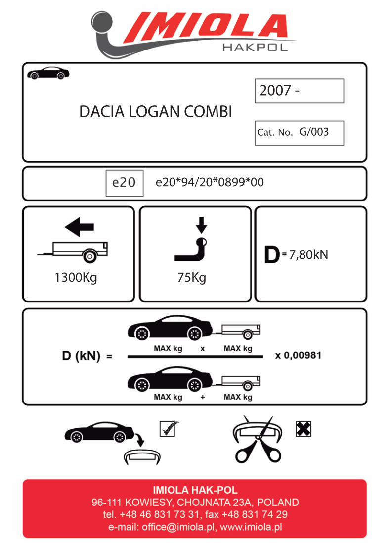
x1
x1
x2
x1
x1
M12x70 2
M12x35
M10x100
M12
M10
Ø36xØ13x3
12,2 6
10,2
13 6
10,5

A
B
C
C
E
F
Pkt. 1
Pkt. 2
Pkt. 2
Pkt. 1
D
D
G/00
3Ma
rkaod
200
7 - >
Dacia
Log
an co
mbi
96-1
11 K
owies
y, Ch
ojnata
23 A
tel.
+48
46 8
31 7
3 31
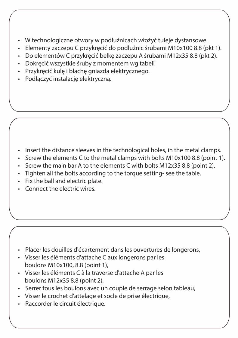
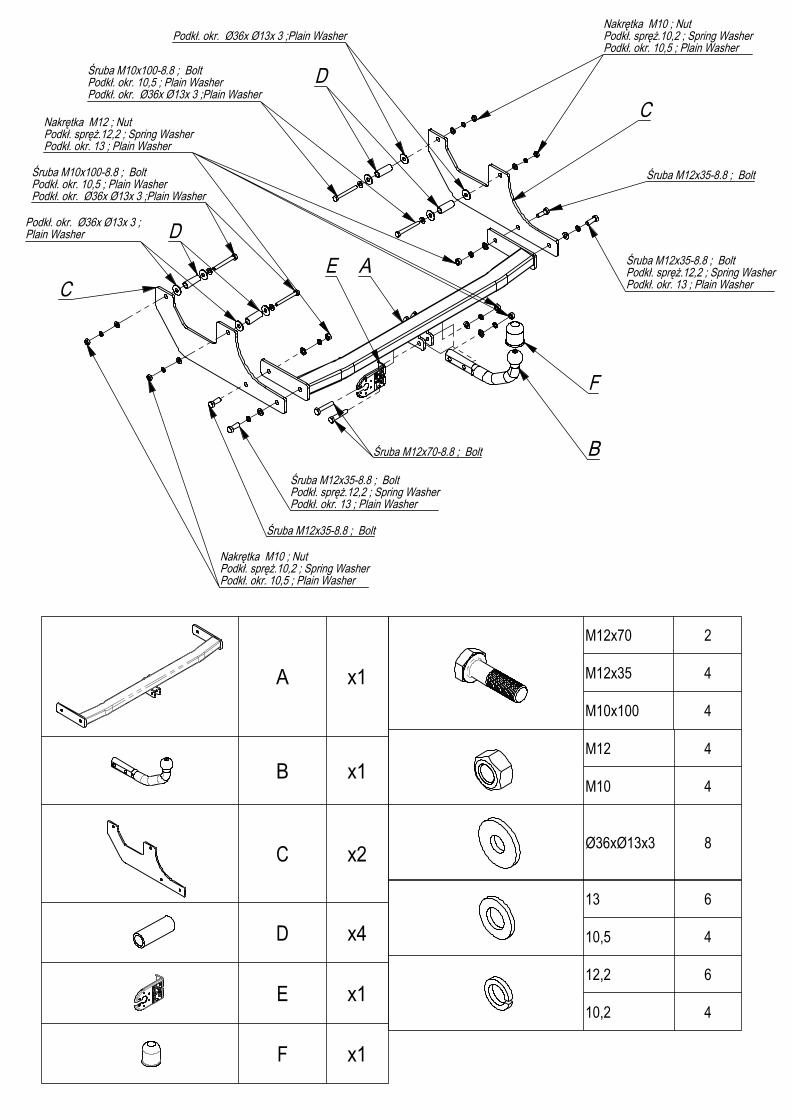
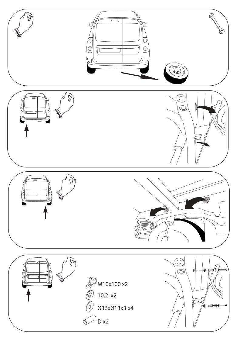
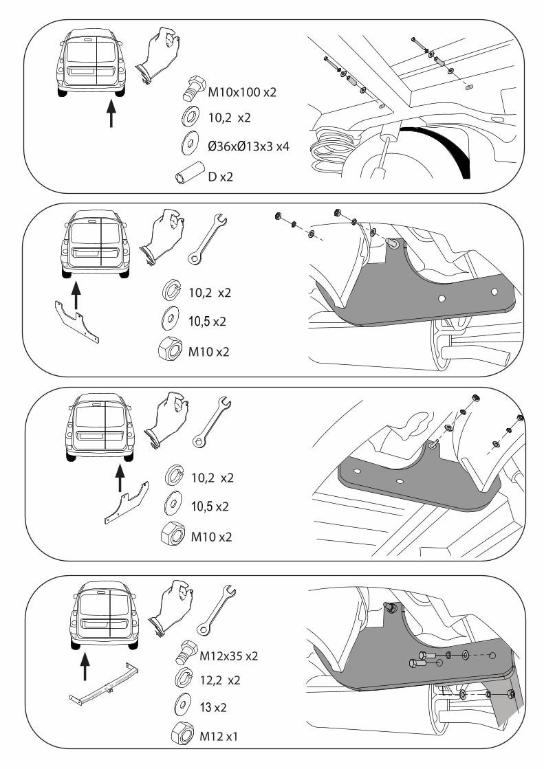
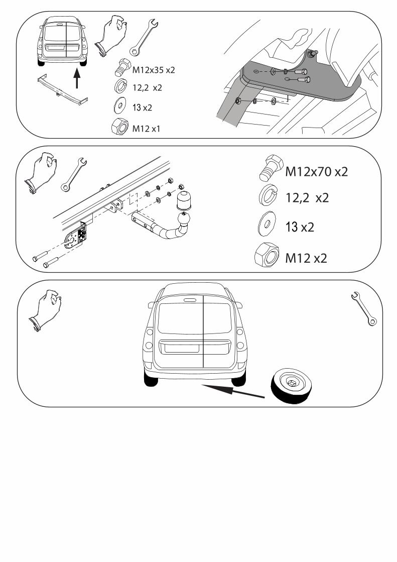
• W technologiczne otwory w podłuźnicach włożyć tuleje dystansowe.• Elementy zaczepu C przykręcić do podłuźnic śrubami M10x100 8.8 (pkt 1).• Do elementów C przykręcić belkę zaczepu A śrubami M12x35 8.8 (pkt 2).• Dokręcić wszystkie śruby z momentem wg tabeli• Przykręcić kulę i blachę gniazda elektrycznego.• Podłączyć instalację elektryczną.
• Insert the distance sleeves in the technological holes, in the metal clamps.• Screw the elements C to the metal clamps with bolts M10x100 8.8 (point 1).• Screw the main bar A to the elements C with bolts M12x35 8.8 (point 2).• Tighten all the bolts according to the torque setting- see the table.• Fix the ball and electric plate.• Connect the electric wires.
• Placer les douilles d'écartement dans les ouvertures de longerons,• Visser les éléments d'attache C aux longerons par les boulons M10x100, 8.8 (point 1),• Visser les éléments C à la traverse d'attache A par les boulons M12x35 8.8 (point 2),• Serrer tous les boulons avec un couple de serrage selon tableau,• Visser le crochet d'attelage et socle de prise électrique,• Raccorder le circuit électrique.
M10x100 x2
10,2 x2
Ø36xØ13x3 x4
D x2
M10x100 x2
10,2 x2
Ø36xØ13x3 x4
D x2
10,2 x2
10,5 x2
M10 x2
10,2 x2
10,5 x2
M10 x2
M12x35 x2
12,2 x2
13 x2
M12 x1
M12x70 x2
12,2 x2
13 x2
M12 x2
M12x35 x2
12,2 x2
13 x2
M12 x1