
CVM211P
9
Pneumatic Division Richland, Michigan 49083 Installation & Service Instructions CVM211P Vacuum Application Case (Part Number: Vacuumdemo) ISSUED: Februar y, 2004 Supersedes: None Doc.# CVM-211P, NPR040226 WARNING To avoid unpredictable system behavior that can cause personal injury and property damage: Disconnect electrical supply (when necessary) before installation, servicing, or convers ion. • Disconnect air su pply and de press urize all air lines co nnecte d to this product before installation, servicing, or conversion. • Operate within the manufacturer’s specified pressure, temperature, and other conditions listed in these instructions. • Medium must be mois ture-f ree if ambi ent tempe ratur e is below freezing. • Servic e accor ding to pro cedur es listed in th ese instr uction s. • Install ation, s ervice, and con vers ion of these pro ducts must be performed by knowledgeable personnel who understand how pneumatic products are to be applied. • After insta llation , servi cing, or con ver sion, air and elec trical supplies (when necessary) should be connected and the product tested for proper function and leakage. If audible leakage is present, or the product does not operate properly, do not put into use. • Warnin gs and sp ecificat ions on th e pro duct shou ld not be covered by paint, etc. If masking is not possible, contact your local representative for replacement labels. ! Introduction Follow these instructions when installing, operating, or servicing the product. WARNING FAILURE OR IMPROPER SELECTION OR I MPROPER USE OF THE PRODUCTS AND/OR SYSTEMS DESCRIBED HEREIN OR RELATED ITEMS CAN CAUSE DEATH, PERSONAL INJURY AND PROPERTY DAMAGE. This document and other information from The Company, its subsidiaries and authorized distributors provide product and/or system options for further investigation by users having technical expertise. It is important that you analyze all aspects of your application, including consequences of any failure and review the information concerning the product or systems in the current product catalog. Due to the variety of operating conditions and applications for these products or systems, the user, through its own analysis and testing, is solely responsible for making the final selection of the products and systems and assuring that all performance, safety and warning requirements of the application are met. The products described herein, including without limitation, product features, specifications, designs, availability and pricing, are subject to change by The Company and its subsidiaries at any time without notice. EXTRA COPIES OF THESE INSTRUCTIONS ARE AVAILABLE FOR INCLUSION IN EQUIPMENT / MAINTENANCE MANUALS THA T UTILIZE THESE PRODUCTS. CONTACT YOUR LOCAL REPRESENTATIVE. ! Overview The vacuum application case is for demonstration of Parker’ s V acuum Components and System Solutions. Thi s tool is intended not only for product demonstration but for application sizing and troubleshooting vacuum systems at a customer’s site. The vacuum application case has inline and integrated generators. Each Generator has different nozzle diameters for different flow and response time ev aluations. The integrated generators are connected to a small PLC and timer for system response time evaluations. Set Up The vacuum application case has a 110 V AC electrical connector . T here is a power supply in the bottom that provides 24 VDC power for the I/O. Power is turned on with the On / Off Switch (5) on the front Panel. Pl ug in the unit and turn the switch on. The 05R Regulator has an 8mm OD tube connection. 8mm is equivalent to a 5/16 OD tube. If other types of connection are required, the Regulator has BSPP ports. Connect this to Positi ve Pressure not to exceed 250 PSI or the rated pressure of the tubing that is connected to the Primary Inlet of the Regulator. A djust the secondar y pressure to 70 PSI. The secondary pressure is indicated on the MPS-31 Positive Pressure Sensor (G). Item Part Number Description A. CV-20HSN V acuum Generator B. CV -10HSN Vacuum Generator C. MCA- 10H S- N1N1N1 V acuum Gener at or D. MC3S10HS9324 PB Int eg ra ted Vacuum Generat or E. MC 2S1 001 L24 BLN Integr at ed Vacuum Generator F . CEK 27HS 21N24 BLN Int egr ate d Vacu um Gen era tor G. MPS-V31N -NG MPS-31 Vacuum Sensor, Panel Mount H. MPS-P31N -NG MPS-31 Inlet Pres sure Sensor, Panel Mount I. VFL-88 Inline V acuum Filter J. 05R213A01 Regulator and Bracket K. P2M1T4ES2C Moduflex Inline Valve F A B C I K E D G H J G H 1 2 3 4 5
Transcript of CVM211P

8/12/2019 CVM211P
http://slidepdf.com/reader/full/cvm211p 1/8
Pneumatic DivisionRichland, Michigan 49083
Installation & Service InstructionsCVM211PVacuum Application Case(Part Number: Vacuumdemo)ISSUED: February, 2004Supersedes: NoneDoc.# CVM-211P, NPR040226
WARNINGTo avoid unpredictable system behavior that can cause personalinjury and property damage:
Disconnect electrical supply (when necessary) beforeinstallation, servicing, or conversion.
• Disconnect air supply and depressurize all air lines connectedto this product before installation, servicing, or conversion.
• Operate within the manufacturer ’s specified pressure,temperature, and other conditions listed in these instructions.
• Medium must be moisture-free if ambient temperature is belowfreezing.
• Service according to procedures listed in these instructions.• Installation, service, and conversion of these products must be
performed by knowledgeable personnel who understand howpneumatic products are to be applied.
• After installation, servicing, or conversion, air and electrical
supplies (when necessary) should be connected and the producttested for proper function and leakage. If audible leakage ispresent, or the product does not operate properly, do not putinto use.
• Warnings and specifications on the product should not becovered by paint, etc. If masking is not possible, contact yourlocal representative for replacement labels.
!
IntroductionFollow these instructions when installing, operating, or servicingthe product.
WARNING
FAILURE OR IMPROPER SELECTION OR IMPROPER USE OF THEPRODUCTS AND/OR SYSTEMS DESCRIBED HEREIN OR RELATEDITEMS CAN CAUSE DEATH, PERSONAL INJURY AND PROPERTYDAMAGE.This document and other information from The Company, its subsidiariesand authorized distributors provide product and/or system options forfurther investigation by users having technical expertise. It is importantthat you analyze all aspects of your application, including consequencesof any failure and review the information concerning the product orsystems in the current product catalog. Due to the variety of operatingconditions and applications for these products or systems, the user,through its own analysis and testing, is solely responsible for makingthe final selection of the products and systems and assuring that allperformance, safety and warning requirements of the application aremet.The products described herein, including without limitation, productfeatures, specifications, designs, availability and pricing, are subject tochange by The Company and its subsidiaries at any time without notice.
EXTRA COPIES OF THESE INSTRUCTIONS ARE AVAILABLE FORINCLUSION IN EQUIPMENT / MAINTENANCE MANUALS THAT UTILIZETHESE PRODUCTS. CONTACT YOUR LOCAL REPRESENTATIVE.
!
OverviewThe vacuum application case is for demonstration of Parker’sVacuum Components and System Solutions. This tool isintended not only for product demonstration but for applicationsizing and troubleshooting vacuum systems at a customer’ssite.
The vacuum application case has inline and integratedgenerators. Each Generator has different nozzle diameters fordifferent flow and response time evaluations. The integratedgenerators are connected to a small PLC and timer for systemresponse time evaluations.
Set Up
The vacuum application case has a 110 VAC electricalconnector. There is a power supply in the bottom that provides24 VDC power for the I/O. Power is turned on with the On / OffSwitch (5) on the front Panel. Plug in the unit and turn theswitch on.
The 05R Regulator has an 8mm OD tube connection. 8mm isequivalent to a 5/16 OD tube. If other types of connection arerequired, the Regulator has BSPP ports. Connect this toPositive Pressure not to exceed 250 PSI or the rated pressureof the tubing that is connected to the Primary Inlet of theRegulator. Adjust the secondary pressure to 70 PSI. Thesecondary pressure is indicated on the MPS-31 PositivePressure Sensor (G).
Item Part Number Description
A. CV-20HSN Vacuum GeneratorB. CV-10HSN Vacuum GeneratorC. MCA-10HS-N1N1N1 Vacuum GeneratorD. MC3S10HS9324PB Integrated Vacuum GeneratorE. MC2S1001L24BLN Integrated Vacuum GeneratorF. CEK27HS21N24BLN Integrated Vacuum GeneratorG. MPS-V31N-NG MPS-31 Vacuum Sensor, Panel MountH. MPS-P31N-NG MPS-31 Inlet Pressure Sensor,
Panel MountI. VFL-88 Inline Vacuum FilterJ. 05R213A01 Regulator and BracketK. P2M1T4ES2C Moduflex Inline Valve
F A
B
CI
K
E
D
G H
J
G H 1 2 3 4 5

8/12/2019 CVM211P
http://slidepdf.com/reader/full/cvm211p 2/8
Vacuum Application Case CVM-211P
2
Vacuum Application Sensors shipped from the factory in kPa.Change the Sensors to desired units. All programming guidesare in the Sensor Section of the Vacuum Catalog.
Set the MPS-31 (G) to units of PSI and to Window Comparatoroutput Mode. If Primary pressure is set at 70 PSI, set a-1 = 65and B-1 to 73. During Demonstration of the vacuumgenerators, if primary pressure drops below 65 PSI or above73, the LED readout will change from Green to Red. Displaycolors can be changed in Mode 6 of the programming. Thisdemo of the MPS-31 can be done by manually adjusting the
secondary pressure on the 05R or by operating the vacuumgenerator. This a good demonstration of why to have avacuum sensor on an FRL. Visually, RED / GREEN LEDfunction will get the attention of maintenance faster than agauge needle.
Presentation - Inline Generators
This area of the vacuum application case has the inlinegenerators. All vacuum Generators receive compressed airfrom the Moduflex Valve. The inlet of the Moduflex valve isconnected underneath the panel to the output of theRegulator.
Connect the output tube from the Moduflex Valve to the inletport of the generator that you want to demonstrate. Connect
the Vacuum line with the VFL inline filter (I) to the generatorvacuum port that you want to demonstrate.
To Operate the Moduflex valve, turn the selector knob (2) onthe front panel to “CV” position and press the vacuum button(3). Blow-off button (4) does not function when the selectorknob is in “CV” Position.
The vacuum outlet line is connected to the Vacuum Sensor (H)on the front panel. Program this sensor with units of measurein inHg, and in the Hysteresis Output Mode. Program Setpoints H-1 and h-1, so that part off pressure is below H-1 andpart on Pressure is above H-1. The display should changefrom Red to Green. If not, this can be programmed in Mode 6of the programming.
While operating the inline vacuum generators, it can bediscussed why it is important to have some type of sensorinline to the application. Vacuum confirmation will reduce cycletime and give a positive feed back to the PLC that the nextstep in the machine cycle can be started.
Presentation - Integrated Generators
This area of the vacuum application case has the integratedgenerators. All vacuum Generators receive compressed airfrom the output port of the Regulator.
Vacuum Application Sensors shipped from the factory are inunits of kPa. Change the Sensors to desired units. Allprogramming guides are in the Vacuum Catalog.
Set the outputs of these sensors to Hysterisis Mode. Theoutput of each sensor is connected to the timer (1) on the frontpanel. For demonstration of response time on the samevolume, the set points of each sensor should be set to thesame level. H-1 and h-1 should be equal on all sensors.
To operate any of these generators, turn the selector knob (1)on the front panel to the position of the generator series thatyou wish to demonstrate. MC3, MC2 or CEK. To Operate theGenerator, press the vacuum button (3) to create vacuum flowand press Blow-off button (4) to create blow-off pressure. TheVacuum Sensor is not functional on the front panel. Degree ofvacuum can be viewed on the sensor that is mounted to eachgenerator. Only the vacuum button is required to operate theMC2 generator since this generator has the MVS-201 SeriesSensor.
The timer starts as soon as the vacuum button (3) is pressed.The Time stops when the Output (H-1) of the sensor isreached. When the blow-off button (4) is pressed, this resetsthe timer. Timer directions are included with this document.The Timer function gives you the ability to show the responsetime differences between the MC3, MC2 and CEK. If thegenerator is connected to a customers actual application it willindicate real response time for his application. I believe thesefeatures to be key in being involved with the design of thesystem as well as being in the drivers seat for the purchaseorder. It will make your competitors have to show their systemcomponents in the same way.
There are 3 different generators included in this area of thevacuum application case.
K
A
B
CI
J
F
E
D

8/12/2019 CVM211P
http://slidepdf.com/reader/full/cvm211p 3/8
Vacuum Application Case CVM-211P
3
PFG Cup
On
Off
Air
EconomizingValve
Check Valve
Sensor
VenturiN.C. MasterValve
N.C. MasterValve
Blow-offPilotValve
Filter
FlowControl
15
4
3
2
VacuumValve
MC3 with MPS-9 Sensor (D)This generator is 10mm wide with a MPS-9 Sensor. The MPS-9 Sensor provides both analog and an Open Collector Outputwith a response time of 1msec. MC3 Generator is forSupersonic lightweight applications that typically involve butare not limited to chip mounting and chip testing.
Customer BaseCustomers looking for high speed pick and placeapplications.
• Vacuum to 20" hg in 20 milliseconds• Blow off response in 10 milliseconds
Key Points• Speed of response time. Use the timer to show
evacuation time differences between MC2 and MC3.
• 10mm Width Generator. Manifold or single sliceapplications.
• With or without Sensor Options.
• There is a cost difference. If the customer wantsspeed, MC3. If the customer wants speed but forfactory Automation MC2. A difference of 20 msecs.Worth it - maybe, then they will pay for it.
MC2 with MVS-201 Sensor (E)The MC2 Generator is versatile Lightweight Generator forhigh-speed applications with multiple choices for sensoroptions.
Sensor OptionsMPS-6
• Low Cost Sensor with 1 Normally Open and 1Normally Closed Open Collector Output withtrim pot.
• 1 msec response time
MPS-2
• LED options with 2 independent Open CollectorOutputs
• Display options
• 2.5 msec response time.
MVS-201• LED Options
• 1 Open Collector Output for both Part PresenceSignal and Blow-off Confirmation.
• 1 Input for Vacuum Control with Timer Controls forlength of vacuum and blow-off functions.
Customer BaseAll semiconductor, Electronic Test and Assembly
OEMS, Injection Mold AutomationKey Points
Reduction of wiring: All wiring is through an M8 4 PinConnector. The Output signal is passed though theclosed sensor output 1 which is connected to thevacuum valve. Show the wiring differences between theMC3 / CEK and the MC2.
Ease of Programming: System blow-off parameterscan be changed at the sensor versus having to changethe PLC program. Air Economizing functions can beadded by changing programs functions. Show howchanging the timer functions on the MVS-201 affect theapplication of the automatic blow-off.
Reduction of PLC / PC Outputs: No Additional Outputfrom the PLC is required for the blow-off function. Thiswill save an Input per generator.
Reduction of PLC / PC Inputs: Output is not onlyvacuum part presence but is a blow-off indicator aswell. Show it with Output LED2 on the sensor that iseliminated at vacuum presence signal and blow-offsignal. This can be shown in the catalog as well in theMVS-201 sensor section.
The MVS-201 sensor has 3 programming modes.
OP1 Air Economizing Function.
OP2 Vacuum Timer Option
OP3 Signal Controlled Vacuum
The features of each operating mode can be shown anddiscussed with the customer by switching between operationmodes. The catalog section on the MVS-201 Sensors is anice additional tool to show what this sensor offers.
Pre-Programming OP1, OP2 and OP3 is ideal for purpose ofthis demonstration. The differences between OP1 and OP3give the best visual and audio effect. The Parameters of OP1,OP2 and OP3 are stored in the sensor EEPROM and areready to go each time you switch between operational modes
of the sensor.
CEK Emergency Stop Generatorwith MPS-2 Sensor (F)The CEK Integrated Generator is the most impressivegenerator in the vacuum application case. This Generator willcreate sales. There is no competition to the CEK Generator.
The CEK Generator is the basic CVK generator but withEmergency Stop Functions. If the customer is not interestedin the CEK Emergency Stop Functions, you can still discussthe CVK Generators, just different valves on the top.
To operate turn the selector switch to CEK and push thevacuum button. This will turn the pilot valve on and createvacuum. At the Set Point H-1 of the sensor, the AirEconomizing function will start. The Air Economizing Valveinhibits the vacuum pilot signal and exhausts teh pressure onthe master valve. This stops the CEK from Creating Vacuum

8/12/2019 CVM211P
http://slidepdf.com/reader/full/cvm211p 4/8
Vacuum Application Case CVM-211P
4
Pressure. The Check valve will hold the vacuum pressure inthe cup.
Any time the vacuum pressure falls below through theHysterisis set point (H-1 minus h-1) the generator will turnback on.
Set point H-2 of the sensor will stop the timer to showresponse time of the system.
The main feature of the CEK is the Emergency Stop function.
If power is disrupted during vacuum on, the generator willdefault to vacuum on by passing air over the nozzle / diffuserset. It will override the Air Economizing function. If power isdisrupted during vacuum off, the generator will NOT default tocreate vacuum. It will stay in the off condition. The benefit ofParker/Convum Emergency Stop functions is that duringpower disruption, it will create vacuum if the PLC/PC lastcommand was to create vacuum, or won’t create vacuum if thePLC/PC’s last command was to have vacuum off.
Demonstrate the Emergency Stop FunctionAdhere a cup to something that has low or no leakage.Show the Air Economizing function. While a cup is
adhered to a product, turn the power off with the On / Off switch (5) on the front panel. This simulates loss ofpower. The Generator defaults to creating vacuum. Turnthe power on and the unit will go back to AirEconomizing.
Some customers use normally open valves to create anEmergency Stop function. Refer to the pneumatic circuitin Figure 1. In this case, a customer takes away thePLC/PC output signal to adhere a cup to a part. In theevent of power loss, the system will not drop a partbecause it is the lack of power to the valve that createsvacuum flow. But, if this system shown is not holding apart, it defaults to creating vacuum and compressed airis used even though no part is present. This systemcould bleed all of the air in the compressed air system.
Figure 1
In the event of power loss, the CEK defaults to usingcompressed air when the last command from the PLC/ PC was to create vacuum.
Demonstrate this function. With the CEK not creatingvacuum, turn the power off with the On / Off switch (5).Nothing happens. The CEK will conserve compressedair with the Air Economizing function and theEmergency Stop function.
CVK / CEK check valve has very low leakage. Testing
CV
PFG Cup
Normally OpenAir Supply
Filter
shows a vacuum loss of only 0.63 inHg over a 24 hourperiod on a new generator.
Customer BaseCombination of Air Economizing with the EmergencyStop System makes the CEK the ultimate vacuumcircuit for material handling.
RoboticsAir Economizing is a feature of the CVK that would beof particular interest to Robotic customers with non-
porous applications.Kuka, Motoman, Nachi, Kawasaki, Mitsubishi
AutomotiveGM, Ford, Chrysler, Honda, Toyota, Nissan,
Tier One AutomotiveMaterial Handling
Sheet Metal HandlingStamping CompaniesPlastic Injection Molding Users.
Key Points• Large flow rates
• Emergency Stop ModesPower failure rides the generator to full vacuum
potential
• DeviceNet CapableAir Economizing Function Built into Electronic
Board
DeviceNet Failure rides the generator to fullvacuum potential
• Sensor OptionsMPS-2, MPS-6
• Built in check valve in the event of loss of air.Minimal Leakage on Check Valve.
8/12/2019 CVM211P
http://slidepdf.com/reader/full/cvm211p 5/8
Vacuum Application Case CVM-211P
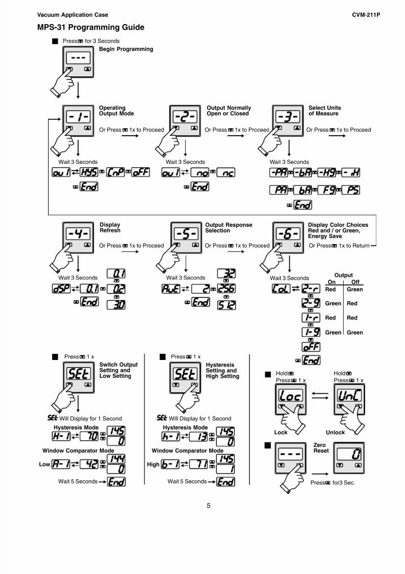
5
Output NormallyOpen or Closed
OperatingOutput Mode
DisplayRefresh
Begin Programming
Select Unitsof Measure
Switch OutputSetting andLow Setting
HysteresisSetting andHigh Setting
Hysteresis ModeHysteresis Mode
Window Comparator Mode
Output ResponseSelection
Display Color ChoicesRed and / or Green,Energy Save
Lock Unlock
1
2 3
4
ZeroReset
5
Red
Green
Red
Green
Green
Red
Red
Green
Low High
Press for 3 Seconds
Press 1 x Press 1 x
HoldPress 1 x
HoldPress 1 x
Press for3 Sec.
Or Press 1x to Proceed
Or Press 1x to Proceed Or Press 1x to Proceed Or Press 1x to Return
Or Press 1x to Proceed Or Press 1x to Proceed
Wait 3 Seconds
Wait 3 Seconds
Will Display for 1 Second Will Display for 1 Second
Wait 5 Seconds
Wait 3 Seconds Wait 3 Seconds
Wait 3 Seconds Wait 3 Seconds
OutputOn Off
Window Comparator Mode
Wait 5 Seconds
MPS-31 Programming Guide

8/12/2019 CVM211P
http://slidepdf.com/reader/full/cvm211p 6/8
Vacuum Application Case CVM-211P
6
MVS-201 Programming Guide
2 1
Operating Mode 11
2 1
Press 1x
Operating Mode 2 Operating Mode 3
Switch Output4
2 1 OutmodeOpen orClosed
Screen SaverPeak Vacuum LevelVacuum Level Response TimeBlow-off Time
2 32 1

8/12/2019 CVM211P
http://slidepdf.com/reader/full/cvm211p 7/8
Vacuum Application Case CVM-211P
7
MPS-2 Programming Guide
Output Set Openor Closed SelectingUnits of MeasureEasy ModeActivation
Output Mode 1Hysteresis orWindowComparator
Output Mode 2Hysteresis orWindowComparator
Output 1 Setting Output 2 Setting Automatic Teach Mode& Auto Surveillance
Display RefreshSettings / OutputResponse TimeInterval
Lock Unlock
Special DisplayFeatures
ZeroReset
Display Peak ValueBottom Value orTheir Difference
VacuumCycle
ReleaseCycle
Peak Value
BottomValue
1 2 3
4 5 6
7 8 9
1011 12
2 1
2 1
2 12 1
2 1
2 1
2 1
2 1 2 12 1 2 1
2 1
2 1
2 1
2 1
Press 6x
Press for 3 Seconds
Press 1x
HoldPress 1x
Press 7x Press 8x
Press 1x
Press 3x
Press 2x
Press 5x
Press 4x
HoldPress
HoldPress Press 1x
Window ComparatorMode
Window ComparatorMode
HysteresisMode
HysteresisMode
Low Low
High High
8/12/2019 CVM211P
http://slidepdf.com/reader/full/cvm211p 8/8
Vacuum Application Case CVM-211P
8
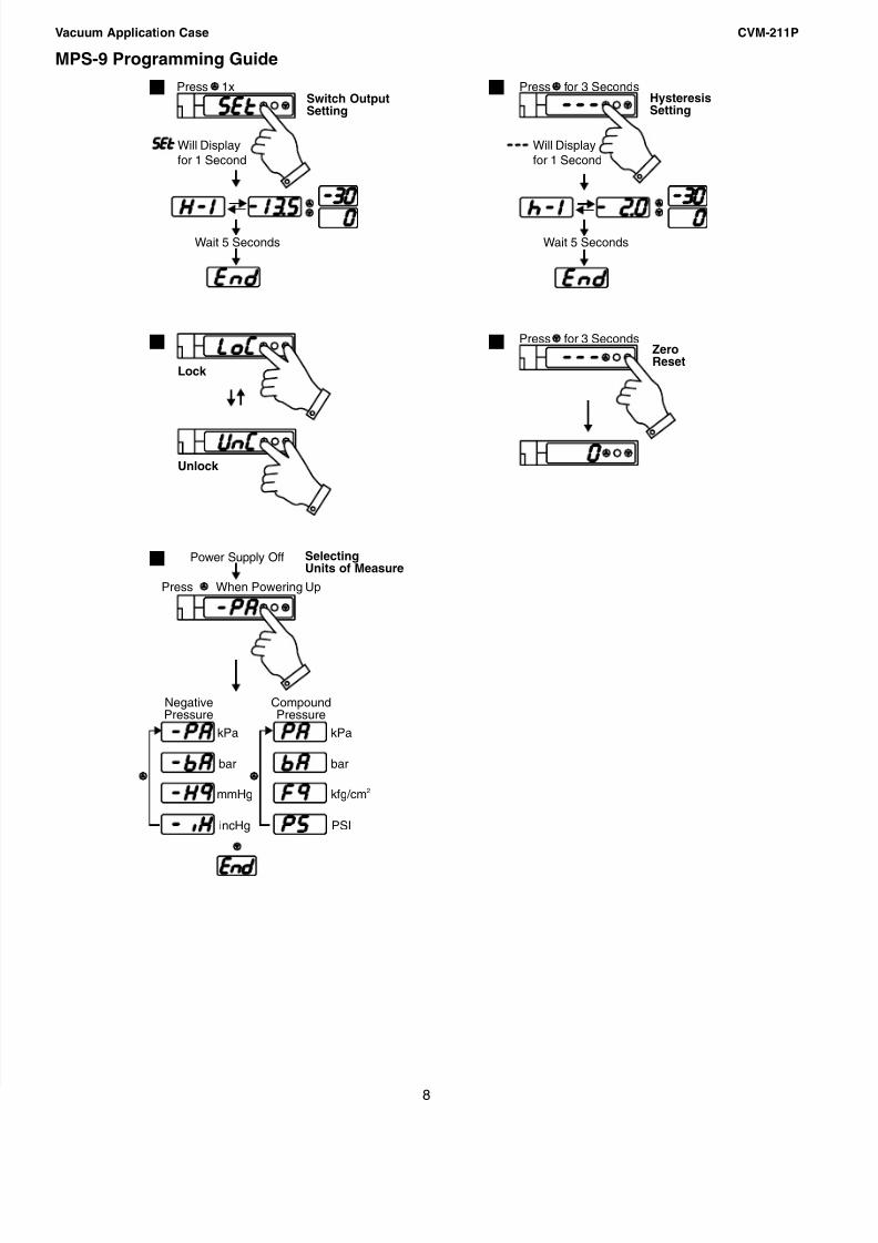
MPS-9 Programming Guide
Switch OutputSetting
HysteresisSetting
Lock
Unlock
SelectingUnits of Measure
1 2
3
5
Wait 5 Seconds Wait 5 Seconds
Power Supply Off
4 ZeroReset
NegativePressure
CompoundPressure
kPakPa
bar bar
mmHg kfg/cm 2
incHg PSI
Press 1x Press for 3 Seconds
Press for 3 Seconds
Press When Powering Up
Will Displayfor 1 Second
Will Displayfor 1 Second


