Cisco Prime Network Administration Guide, 3 Cisco Prime Network 3.10 Administrator Guide OL-28066-01...
378
xi Cisco Prime Network 3.10 Administrator Guide OL-28066-01 Preface This guide describes how to administer Cisco Prime Network (Prime Network) using the Prime Network GUI client, utility scripts, and registry modifications. This preface contains the following sections: • New and Changed Information, page xi • Organization of This Guide, page xiii • Conventions, page xiv • Related Documentation, page xv • Obtaining Documentation and Submitting a Service Request, page xv New and Changed Information The following table describes information that has been added or changed since this guide was first published. Date Released Revision Location May 2, 2012 Updated the documentation for reduced polling fail-safe mechanism to indicate this option is enabled by default. Reduced Polling, page 3 Added entity mib in the configuration settings for the Cisco IOS XR devices. Cisco IOS XR Devices—Required and Recommended Settings, page 8 October 4, 2013 Using reports with Prime Central—Added: Prime Network users will only be allowed to view reports if an additional session is configured in their Prime Central user management settings. Use Prime Network with Cisco Prime Central, page 1-10 March 25, 2013 Creating proxy for devices behind firewalls—Resolved CSCuf49036 and CSCuf54352. Corrected procedure for connecting to devices when there is a firewall between a GUI client and a managed device. Manage Configurations with Firewalls (Device Proxy), page 23
Transcript of Cisco Prime Network Administration Guide, 3 Cisco Prime Network 3.10 Administrator Guide OL-28066-01...

xiCisco Prime Network 3.10 Administrator Guide
OL-28066-01
Preface
This guide describes how to administer Cisco Prime Network (Prime Network) using the Prime Network GUI client, utility scripts, and registry modifications.
This preface contains the following sections:
• New and Changed Information, page xi
• Organization of This Guide, page xiii
• Conventions, page xiv
• Related Documentation, page xv
• Obtaining Documentation and Submitting a Service Request, page xv
New and Changed InformationThe following table describes information that has been added or changed since this guide was first published.
Date Released Revision Location
May 2, 2012 Updated the documentation for reduced polling fail-safe mechanism to indicate this option is enabled by default.
Reduced Polling, page 3
Added entity mib in the configuration settings for the Cisco IOS XR devices.
Cisco IOS XR Devices—Required and Recommended Settings, page 8
October 4, 2013 Using reports with Prime Central—Added: Prime Network users will only be allowed to view reports if an additional session is configured in their Prime Central user management settings.
Use Prime Network with Cisco Prime Central, page 1-10
March 25, 2013 Creating proxy for devices behind firewalls—Resolved CSCuf49036 and CSCuf54352. Corrected procedure for connecting to devices when there is a firewall between a GUI client and a managed device.
Manage Configurations with Firewalls (Device Proxy), page 23

xiiCisco Prime Network 3.10 Administrator Guide
OL-28066-01
Preface
March 5, 2013 VNEs in maintenance mode—Resolved CSCue51561. Corrected description of maintenance mode to say that when a VNE is in maintenance state, it does not process traps and syslogs. Also clarified that maintenance VNEs do passively participate in correlation flows.
Table 4-3 in Check VNE Communication State (Connectivity), page 4-6
Integrity tests—Resolved CSCud92376. Added the jobSchedulerPruning test.
Table 8-4 in How the Data Purging Mechanism Works, page 8-6
Unit redundancy—Resolved CSCue38276. Clarified that units can only be specified as standby or active during the Prime Network installation process. Removed erroneous text that said standby units were not displayed in the GUI client (they are displayed).
Overview of Unit and Process Protection, page 5-1
March 5, 2013 (continued)
VNE Inventory option—Resolved CSCue41515. Added text that explains what is shown when user right-clicks VNE and chooses Inventory versus Properties.
Check Device Discovery, VNE Status, and VNE States, page 4-2
Device prerequisites:
• Resolved CSCue51335—Added procedure for configuring login sequence for CPT devices on CPT VNEs.
Cisco Carrier Packet Transport Devices—Required Settings, page A-13
• Resolved CSCue82126—Added details about prerequisites for adding UCS VNEs and included an overview of the procedure for UCS VNEs.
Cisco Unified Computing System Devices—Required Settings, page A-14
• Resolved CSCud16392—Added a missing SNMPv3 command that configured the write community on a device. If not set, Change and Configuration Management would not be able to back up the device's configuration.
SNMP Traps and Informs—Required Device Settings, page A-15
Event Collector—Resolved CSCue73373. Fixed syntax errors in procedure for configuring multiple Event Collectors (erroneously used XIDIP on non-Event Collector examples).
Configuring and Enabling Multiple Event Collectors, page 9-12
Reduced Polling—Resolved CSCue82130. Fixed procedure for enabling the fail-safe option; the command for adding the registry key was missing.
Adaptive Polling, page 12-10
January 24, 2013 Adaptive polling—Resolved CSCud98871. Fixed figure that illustrates the adaptive polling mechanism. It was missing the indicator for when a VNE reverts from slow polling back to normal polling. Also fixed text that said a VNE was moved to CPU-only polling after consecutive Maintenance Tolerance polls. (See section for clarification.)
Figure 12-5 on page 11, and Adaptive Polling, page 12-10
Data purging—Resolved CSCud89536. Corrected name of workflow engine integrity test.
Table 8-4
Protection groups—Resolved CSCud31099. Clarified that if one unit in a protection group has a database connection, the other units must also have a database connection.
Create a New Unit Protection Group, page 5-9
Device prerequisites—Resolved CSCue21401. Added prerequisites for Cisco Unified Computing System (UCS) devices.
Cisco Unified Computing System Devices—Required Settings, page A-14
November 2012 Initial release. —
Date Released Revision Location

xiiiCisco Prime Network 3.10 Administrator Guide
OL-28066-01
Preface
Organization of This Guide
Chapter/Appendix Title Description
1 Set Up Prime Network and Its Components
Lists the major setup tasks you should perform after installing the product, such as setting up fault management, system redundancy, data purging schedules, and so forth.
2 Manage the Prime Network Software Image and Backups
Managing and updating the base software image and licenses, backing up and restoring data, and adding new NE support by downloading and installing new Device Packages.
3 Manage the Prime Network Components: Gateway, Units, and AVMs
Introduces you to the system architecture: Gateways, units, AVMs, and VNEs, including describing the reserved AVMs used by the system. Explains how to check the current properties of components and how to stop and restart them. Also provides procedures for making gateway-level changes such as disabling automatic restarts, controlling client connections, working with firewalls, and so forth.
4 Configure VNEs and Troubleshoot VNE Problems
Guides you through the different methods for adding VNEs. Explains how to manage VNEs, including checking and troubleshooting problems with the communication and investigation states. Also explains how to add new VNE support, and change VNE properties such as its IP address.
5 Manage Redundancy for Units and Processes
Describes unit and process (AVM) protection and redundancy, how to configure AVM redundancy and unit protection groups, and how to change these settings. (For information on gateway high availability, see the Cisco Prime Network 3.10 Gateway High Availability Guide.)
6 Control Device Access Using Device Scopes
Explains the device scope mechanism and how you can use it to control device access, including creating new scopes, moving devices in and out of scopes, and deleting scopes.
7 Manage User Accounts Explains how Prime Network authenticates and authorizes users, how to configure global password rules, control user access to maps, and create, change, and delete user accounts.
8 Manage the Database and System Data
Provides an overview of the Prime Network database and schemas, including the various types of data that is saved, when data is archived and deleted, and the various checks to protect system stability, including the Automatic Overload Prevention feature. It also provides procedures for working with an embedded database.
9 Control Event Monitoring
Explains how Prime Network handles incoming events. It provides best practices for configuring event listening (the Event Collector) on your system, and explains how to set up and forward trap and e-mail notifications.
10 Manage Workflows, Command Scripts, and Activations
Explains what workflows and activations are, how to get information on existing workflows and activations and checking their history, and aborting and deleting workflows.
11 System Security Explains the security mechanism used by Prime Network to ensure the security of all communication within and to and from the system. Also explains how to use an external authentication server for user authentication, how to change system-wide passwords, and how to unlock frozen user accounts and set system-wide authorization controls for various features.

xivCisco Prime Network 3.10 Administrator Guide
OL-28066-01
Preface
ConventionsThis document uses the following conventions:
Note Means reader take note. Notes contain helpful suggestions or references to material not covered in the publication.
12 Perform Advanced VNE Configurations
Describes the polling mechanisms used by Prime Network and how to adjust these settings. Also provides advanced procedures for controlling when a device should be considered unreachable, configuring special collectors and command priorities, and how to stagger VNE Telnet/SSH logins. Also explains how to create a cloud VNE to traverse unmanaged network segments.
A Device Configuration Tasks for Modeling
Provides a list of device configuration commands you should perform on devices to ensure Prime Network can properly communicate with, model, and monitor the device. Also explains the VNE scheme mechanism and which scheme to apply to a VNE, depending on your network.
B Prime Network Log Files
Lists the log files created by the system.
C Manage the Prime Network Registry
Provides a brief introduction to the Prime Network registry and explains how to use the runRegTool command to make registry changes.
D VNE Properties Reference
Lists all of the properties supported for VNEs, from simple properties such as name and IP address, to the various protocols used by VNEs: SNMP, Telnet/SSH, HTTP, TL1, ICMP.
Chapter/Appendix Title Description
Convention Indication
bold font Commands and keywords and user-entered text appear in bold font.
italic font Document titles, new or emphasized terms, and arguments for which you supply values are in italic font.
[ ] Elements in square brackets are optional.
{x | y | z } Required alternative keywords are grouped in braces and separated by vertical bars.
[ x | y | z ] Optional alternative keywords are grouped in brackets and separated by vertical bars.
string A nonquoted set of characters. Do not use quotation marks around the string, or the string will include the quotation marks.
courier font Terminal sessions and information the system displays appear in courier font.
< > Nonprinting characters such as passwords are in angle brackets.
[ ] Default responses to system prompts are in square brackets.
!, # An exclamation point (!) or a pound sign (#) at the beginning of a line of code indicates a comment line.

xvCisco Prime Network 3.10 Administrator Guide
OL-28066-01
Preface
Tip Means the following information will help you solve a problem.
Caution Means reader be careful. In this situation, you might perform an action that could result in equipment damage or loss of data.
Related Documentation
Note We sometimes update the documentation after original publication. Therefore, you should also review the documentation on Cisco.com for any updates.
For all the related documentation for Cisco Prime Network 3.10, see the Prime Network 3.10 Documentation Overview.
The Cisco Prime Network Technology Center is an online resource for additional downloadable Prime Network support content, including help for integration developers who use Prime Network application programming interfaces (APIs). The website provides information, guidance, and examples to help you integrate your applications with Prime Network. It also provides a platform for you to interact with subject matter experts. To view the information on the Prime Network Technology Center website, you must have a Cisco.com account with partner level access, or you must be a Prime Network licensee. You can access the Cisco Prime Network Technology Center at: http://developer.cisco.com/web/prime-network/home.
Obtaining Documentation and Submitting a Service RequestFor information on obtaining documentation, submitting a service request, and gathering additional information, see the monthly What’s New in Cisco Product Documentation, which also lists all new and revised Cisco technical documentation, at:
http://www.cisco.com/en/US/docs/general/whatsnew/whatsnew.html
Subscribe to the What’s New in Cisco Product Documentation as a Really Simple Syndication (RSS) feed and set content to be delivered directly to your desktop using a reader application. The RSS feeds are a free service and Cisco currently supports RSS version 2.0.

xviCisco Prime Network 3.10 Administrator Guide
OL-28066-01
Preface

C H A P T E R
1-1Cisco Prime Network 3.10 Administrator Guide
OL-28066-01
1Set Up Prime Network and Its Components
These topics introduce you to the Prime Network Administration GUI client and describe the setup tasks you should perform after installing Prime Network. These tasks configure Prime Network so that other users can log into the GUI clients and use Prime Network to manage the NEs and network.
• Launch the Prime Network Administration GUI Client, page 1-1
• Setup Tasks for Prime Network, page 1-3
• Use Prime Network with Cisco Prime Central, page 1-10
Launch the Prime Network Administration GUI Client
Note If Prime Network is installed with Cisco Prime Central, logging in is done from the Cisco Prime Portal by choosing Assure > Prime Network > Administration. If a user tries to log into a Prime Network standalone or Webstart client, they will be redirected to the Cisco Prime Portal. For more information about using Prime Network with Cisco Prime Central, see the Cisco Prime Central User Guide.
Prime Network Administration is password-protected to ensure security and is available only to users with Administrator privileges. You can use the Prime Network Administration GUI client to configure a variety of global GUI client properties, such as requiring that passwords be changed on a regular basis, disabling accounts after long periods of inactivity, and locking accounts after repeated unsuccessful login retries. These properties are applied to all of the Prime Network GUI clients, such as Prime Network Vision and Prime Network Events.
Note Users must have Administrator privileges to use the Administration GUI client. All of the procedures described in this guide require Administrator privileges unless otherwise noted.
When you log out of the Administration GUI client, any changes you made are automatically saved, including changes to VNEs. Some changes may require a restart of the AVMs or VNEs, or event the Prime Network gateway. These requirements are noted with the relevant procedures.

1-2Cisco Prime Network 3.10 Administrator Guide
OL-28066-01
Chapter 1 Set Up Prime Network and Its Components Launch the Prime Network Administration GUI Client
Instructions for downloading and installing GUI clients are provided in the Cisco Prime Network 3.10 Installation Guide. To launch the Administration GUI client, use one of the following:
• Start > Programs > Cisco Prime Network > Prime Network Administration to launch the full standalone client. You will have to enter the gateway IP address in addition to your credentials.
• Start > Programs > Cisco Prime Network > gateway-ip > Prime Network Administration to launch the Webstart client. You will have to enter your credentials.
Figure 1-1 identifies the basic parts of the Prime Network Administration window.
Figure 1-1 Prime Network Administration Window
1 Menu bar, with main menu choices. 4 Content area, the main information and work area of the GUI client.
2 Toolbar with action icons (what is displayed depends on your selection).
5 Shortcut menu, displayed by right-clicking an item in the content area.
3 Navigation area, which you use to move among the Administration features.
6 Status bar, which displays the memory usage of the application process, and connection status.

1-3Cisco Prime Network 3.10 Administrator Guide
OL-28066-01
Chapter 1 Set Up Prime Network and Its Components Setup Tasks for Prime Network
Setup Tasks for Prime Network
Note If you are using Prime Network with Cisco Prime Central, some of these features are disabled. See Use Prime Network with Cisco Prime Central, page 1-10.
Table 1-1 Setup Tasks for Prime Network
Feature Setup Tasks Discussed in:
Licenses Verify that your license is registered Register Licenses, page 1-4
System stability Check standby units, control when data is purged, adjust the warning thresholds for AVM memory usage, and control how many clients can connect to a gateway
Set Up Redundancy, Data Purging, and Other Stability Settings, page 1-4
Backups Control where data is saved, and how often backups occur, to protect your data
Set Up the Regular Backup Schedule, page 1-5
Event Management
Configure the Event Collector (which listens for incoming events), e-mail notifications for critical events, and a service to forward trap notifications to other OSSs
Set Up Fault Management, page 1-6
Default AVM size for new AVMs
For VNE and AVM auto-add mechanism, adjust the settings for the size of AVMs and how much of a unit’s memory must remain free
Set Default Size for AVMs, page 1-7
VNE default credentials for SNMP, Telnet, SSH
Set defaults for Telnet/SSH and SNMP credentials (so you do not have to specify them for new VNEs)
Set Default Credentials for VNEs, page 1-7
External user authentication
Control user authentication using an external LDAP server (optional)
Set Up External Authentication, page 1-8
Global rules for users
Configure rules for user passwords, a timeout for when inactive accounts should be disabled, whether credentials are required for running Command Builder commands, whether Prime Network should display a warning message when users run command scripts or activations, whether users can create public reports, and who can schedule jobs
Configure Global Rules for User Accounts, page 1-8
Banners Have Prime Network display a banner whenever a user logs into a client
Create a Login Banner, page 1-9
User accounts and device scopes
Control access to the GUI client and device tasks users can perform
Create User Accounts and Device Scopes, page 1-9
Reports Monitor network and non-network events Set Up Regular Reports, page 1-9
Devices Create VNEs to model devices so Prime Network can manage them
Add Devices to Prime Network, page 4-10

1-4Cisco Prime Network 3.10 Administrator Guide
OL-28066-01
Chapter 1 Set Up Prime Network and Its Components Setup Tasks for Prime Network
Register LicensesWhen you install Prime Network, it automatically activates a 120-day Evaluation license. This allows you to being using the product immediately while you obtain a permanent license. If you do not apply a permanent license by the end of the evaluation period, your connection attempts will be rejected. To apply a new license, see Install and Apply Licenses, page 2-8. For information on licensing and gateway high availability configurations, see Cisco Prime Network 3.10 Gateway High Availability Guide.
Set Up Redundancy, Data Purging, and Other Stability Settings
Create Unit Protection Groups and Designate Standby Units
When you install Prime Network on a unit, the installation procedure queries whether the unit will be a standby unit. A standby unit comes online when a unit in its protection group fails. By default, all units are added to a protection group called default-pg. You can get information on unit and process protection from Overview of Unit and Process Protection, page 5-1.
Note Gateway high availability is described in Cisco Prime Network 3.10 Gateway High Availability Guide.
Adjust Data Purging
To protect system stability and performance, Prime Network purges data from the system regular intervals, depending on the data type. While the default settings are normally sufficient, you can adjust them if necessary as described in Control How Data is Saved, Archived, and Purged, page 8-4. The following table lists the default settings for data purging.
Caution Consult with your Cisco account representative before changing these settings. Making the settings smaller could result in immediate and permanent removal of fault data. Making the settings larger could result in slow data retrieval performance; the system might require additional storage and some database tuning; and backups might require more time.
Data Purged After (Default):
Database—Fault Database 14 days after faults are moved to the archive partition in database table
Database—Event Archive 14 days
Jobs Never purged
Reports 90 days
Backups for systems with external database 5 backups
Backups for systems with embedded database 16 backups
Executed activations 7 days
Executed workflows 7 days
Diagnostics (Graphs) tool 29 days
Configuration Archive files and change logs 30 days
Software Images n/a (manual deletions only)
1-5Cisco Prime Network 3.10 Administrator Guide
OL-28066-01
Chapter 1 Set Up Prime Network and Its Components Setup Tasks for Prime Network
Adjust the AVM Memory Warning Thresholds
If a user-created AVM exceeds 80% of its total memory, Prime Network displays warning indicators to signal a possible load balancing problem. You can quickly respond to these indicators using the Reduce Load option which will adjust VNE allocation (move VNEs to other units). If you want to adjust this threshold, see Manage AVM Memory and Thresholds (Load Balancing), page 3-31.
Control the Maximum Number of Client Sessions for a Gateway
By default, a maximum of 150 clients can be connected to the gateway at one time. This is a system-wide setting. You can adjust this setting, but you should not make it higher than 150 (otherwise system performance may be negatively impacted).
Note Prime Network users can view reports only if an additional user session is configured in their Prime Central user management settings. This is because Prime Central gives Prime Network users one session by default, but the reports function requires an additional session. Refer to the Cisco Prime Central User Guide for more information.
User accounts also have a connection limit. This is a per-user setting. A user will not be able to login if the system-level setting has been reached, or their per-user limitation has been reached.
To adjust the system-wide setting, see Manage Client and User Sessions, page 3-20. To control the per-user setting, see Create a New User Account and View User Properties, page 7-9.
Specify When Events Are Removed from a Vision GUI Client Inventory Window
When an inventory window is opened from the Vision GUI client, it displays an Inventory Event Viewer (normally at the bottom of the window) that lists the recent events for that device. By default, only events that occurred in the last 6 hours are listed. To change this setting, see Change Fault Settings: Clear, Archive, and Purge Fault Data, page 8-8.
Set Up the Regular Backup ScheduleThe timing of your backup schedule depends on whether you have an embedded or external database, and if you have an embedded database, the schedule further depends on the database profile.
If you have an embedded database and you want Prime Network to perform regular backups, you must enable the backup mechanism. This is normally done during installation but you can do it manually by following the procedure in Enable Embedded Database Backups, page 2-14.
Note You should save backups to tape on a daily basis.

1-6Cisco Prime Network 3.10 Administrator Guide
OL-28066-01
Chapter 1 Set Up Prime Network and Its Components Setup Tasks for Prime Network
The following table shows the default backup settings.
For information on the backup and restore mechanism, see Back Up and Restore Process, page 2-9.
Set Up Fault Management
Set Up Prime Network to Receive Events from Devices and Process Them
Make sure that Prime Network is properly configured to receive and save events. You may want to refer to How Prime Network Handles Incoming Events, page 9-1, which provides an illustration of how events are handled by Prime Network.
Check the configuration of the Event Collector, AVM 100. During installation, Prime Network creates Event Collectors on the gateway and all units, but only the gateway Event Collector is started. As VNEs are added, they will automatically register with that Event Collector. Check Setting Up the Event Collector: Supported Scenarios, page 9-6, to make sure you are using the configuration appropriate to your deployment.
By default, when the Event Collector receives raw events, it saves them in the Event Archive in the database. As a result, the server with the running Event Collector must have database connectivity. If you want to disable saving raw events to the Event Archive, see Disable Saving Raw Events to the Event Archive, page 8-12.
Check the configuration of the Fault Agent, AVM 25. The Fault Agent runs on all units and creates tickets based on correlation and event type information, and sends information to the Fault Database so it can be saved and viewed in the GUI clients. AVM 25 always requires database connectivity. If a connection is not available, you can configure AVM 25 to use a proxy AVM 25. (See Configuring Proxy AVM 25 for Units Not Connected to Database, page 9-15.)
Configure Devices to Forward Events to Prime Network
All devices you want Prime Network to manage must configure devices to forward events to Prime Network (where the Event Collector, AVM 100, is running). If you want Prime Network to forward generic events from unmanaged devices, you must enable notification from unmanaged devices using the procedure in the Cisco Prime Network Integration Developer Guide.
Before you add devices to Prime Network (by creating VNEs), be sure to provide all necessary device configuration tasks so that when the VNE is created, Prime Network can properly connect to the device, discover it, and monitor it. Prime Network will automatically choose the best VNE scheme according to
System with: Default Backup Schedule
Embedded Database
Data is backed up according to the profile entered at installation:
• 1-50 actionable events per second—Full backup is performed Saturday at 1:00 a.m.; incremental backups are performed Sunday-Friday at 1:00 a.m.
• 51-250 actionable events per second—Full backup is performed Tuesday and Saturday at 1:00 a.m.
If you did not enable backups during installation, follow the procedure in Enable Embedded Database Backups, page 2-14.
External Database
Gateway data is backed up every 12 hours at 4:00 a.m. and 4:00 p.m, as defined in the crontab file.
Note Prime Network does not back up the external database; it backs up other Prime Network data stored in the system. Use your vendor documentation to back up your external database separately.

1-7Cisco Prime Network 3.10 Administrator Guide
OL-28066-01
Chapter 1 Set Up Prime Network and Its Components Setup Tasks for Prime Network
device type. A VNE’s scheme determines what data will be retrieved for each device, and which commands and protocols Prime Network should use to collect that data. You can also configure a new scheme that will model and monitor the specific information you want.
For information on schemes and device configuration tasks, see Device Configuration Tasks for Modeling, page A-1.
Create E-mail Notifications for Important Events and Tickets
You can configure Prime Network to generate e-mail notifications when an event or ticket occurs. You can base it on severity, type, and other criteria. For information on how to create an Event Notification Service, see Configure Trap and E-Mail Notifications (Event Notification Service), page 9-16.
Forward Event and Ticket Information to Other Applications
You can also use the Event Notification Service to forward specific events and event information to other NMSs or as an e-mail notification. This is described in Configure Trap and E-Mail Notifications (Event Notification Service), page 9-16.
Set Default Size for AVMsWhen you use the AVM auto-add feature (which is recommended), Prime Network will create new AVMs using global properties (memory size and threshold) that you can adjust. Prime Network will also choose the most appropriate unit for you, or you can specify the one you want to use.
This tables describes these settings and their system defaults.
To avoid load balancing problems, Prime Network will warn you when a user-created AVM exceeds 80% of its total memory. You can quickly respond to these indicators by triggering the Reduce Load option which will adjust VNE allocation. If you want to adjust this or any other AVM default settings, see Manage AVM Memory and Thresholds (Load Balancing), page 3-31.
Set Default Credentials for VNEsWhen you create default settings for the SNMP and Telnet/SSH protocols, the settings are automatically applied to all new VNEs
To configure default VNE settings, choose Global Settings > Default VNE Settings.
• Default Telnet SSH Setting are described in VNE Properties: Telnet/SSH, page D-6.
• Default SNMP Settings are described in VNE Properties: SNMP, page D-5.
Field Description Default
Default AVM Size The memory size to be used for auto-added AVMs. 1500 MB
Unit Reserved Memory
The percentage of memory that a unit should keep in reserve. If a unit exceeds its reserved memory, Prime Network will not add any more auto-added AVMs to the unit.
10%

1-8Cisco Prime Network 3.10 Administrator Guide
OL-28066-01
Chapter 1 Set Up Prime Network and Its Components Setup Tasks for Prime Network
To find out what version of SNMP or SSH a VNE is using, right-click the VNE and choose Inventory. This opens the In the device inventory window, click VNE Status. See Figure 4-12 on page 4-45 for an example.
Set Up External AuthenticationIf you want to use external authentication, you must configure Prime Network to communicate with the LDAP server. See Configure Prime Network to Communicate with the External LDAP Server, page 7-17. If you are switching from external authentication to Prime Network authentication, you can import the user information from the LDAP server into Prime Network. That procedure is described in the Import Users from the LDAP Server to Prime Network, page 7-20.
Configure Global Rules for User AccountsThis topic describes the default settings that are applied to user accounts. If you want to change any of these settings, see User Password Settings, page 7-5.
Adjust Rules for User Passwords
By default, Prime Network uses the following password rules
Adjust the Timer for Disabling Accounts Due to User Inactivity
By default, if a user does not log into their account for 30 days, their account is disabled. A disabled account must be re-enabled by a user with Administrator privileges. You can adjust this period if necessary.
Request User Credentials Before Running Scripts and Activations
You can configure Prime Network to require users to enter their device credentials when they execute an activation or command script. When this mode is enabled, the following occurs:
• An Edit Credentials dialog is added to command dialogs and activation wizards. Users must enter their device access credentials (credentials do not have to be re-entered during that session).
• The device user name is added to Provisioning and Audit events.
This mode is disabled by default.
Password Rule Default
Password validity period 30 days
When to begin sending reminders of pending password change 7 days before validity period ends
Permitted attempts before lockout 3 attempts
Password must be different from ___ previous passwords 5 passwords
Password must contain at least four different character types Enabled
Password cannot contain any character that is repeated more than twice consecutively
Enabled
Password cannot contain ___ consecutive characters from the previous password 4 characters
Password cannot contain a replication or reversal of the user name Enabled
Password cannot contain the word _______ Cisco

1-9Cisco Prime Network 3.10 Administrator Guide
OL-28066-01
Chapter 1 Set Up Prime Network and Its Components Setup Tasks for Prime Network
Control Who Can Schedule Jobs
Prime Network provides a per-user authorization mode for scheduling jobs. Enabling and disabling this mode is controlled from global security settings. If the mode is enabled, job scheduling privileges are controlled by the settings in the individual user accounts.
• If this mode is enable and a user is granted privileges, the user can schedule jobs across the product.
• If this mode is enabled and a user is not granted privileges, the job scheduling features in the user’s GUI clients are disabled (for example, from the Tools main menu, or when running reports or Command Builder scripts).
If the global per-user authorization mode is disabled, all users can schedule jobs; the setting in the users’s account is ignored.
By default, this mode is disabled which means all users can schedule jobs.
Allow Shared (Public) Reports
Prime Network also provides a global authorization mode for creating shared or public reports.When a report is public, all users can view the contents; reports are not filtered according to scopes or security privileges. Enabling and disabling this mode is controlled from global security settings. If the mode is enabled, all users can create shared reports.
This mode is disabled by default, which means no users can create public reports.
Create a Login BannerYou can create a message of the day or banner, which is displayed whenever a user logs into a GUI client or the gateway server. See Create a GUI Client Banner Message, page 11-12.
Create User Accounts and Device ScopesOnly a root user account created when you install Prime Network. The root user can then create accounts for other users. The settings in individual user accounts specify the GUI tasks the user can perform.
In addition, the devices a user can see and manage is determined by the device scopes that are assigned to their user account. Device scopes are groups of devices that can be configured and named according to your deployment needs. When you assign a device scope to a user’s account, you also choose a security level for that scope. As the user role determines the GUI tasks a user can perform, the security level determines the tasks a user can perform on devices in the scope. Only one device scope is created by default, the All Managed Elements device scope.
For information on creating user accounts and device scopes, see User Authentication and Authorization Overview, page 7-2.
Set Up Regular ReportsPrime Network provides a robust report framework for generating common reports. You can also create new report templates that will provide the information you need for your deployment. You can schedule any of these reports to run at regular intervals. These are some examples of reports you can generate:
• Most common daily events
• Device with the most events, grouped by severity or by event type
• Database statistics such as event types, correlated events, and so forth

1-10Cisco Prime Network 3.10 Administrator Guide
OL-28066-01
Chapter 1 Set Up Prime Network and Its Components Use Prime Network with Cisco Prime Central
• Trap data showing daily average and peaks, and devices sending the most traps
• Mean Time to Repair faults
You can see all available reports from the Administration GUI client by choosing Reports > Run Report from the main menu. For more information, see the Cisco Prime Network 3.10 User Guide.
Use Prime Network with Cisco Prime CentralPrime Network can be installed as a standalone product or with Cisco Prime Central. When installed with Cisco Prime Central, you can launch Prime Network GUI clients from the Cisco Prime Portal. Cross-launch to and from other suite applications is also supported. The applications share a common inventory.
The Cisco Prime Portal uses a single sign-on (SSO) mechanism so that users need not re-authenticate with each GUI client. All session management features are controlled by the portal (such as client timeouts). If a user tries to log into a standalone GUI client, the user will be redirected to the portal login. The only exception is the emergency user, who will still be allowed to log into a standalone GUI client.
These Prime Network features are disabled in suite mode because they are controlled at the suite level:
• All of the Security Settings that are available from the Global Settings branch (configuring the user authentication method, password rules, and disabling account of the user who has not logged in to the application for a certain number of days).
• Adding, deleting, and changing user accounts (including user passwords)
• Licensing
Prime Network sends the suite regular information about Prime Network server health (ping, CPU usage, and memory usage). At hourly intervals, Prime Network checks the suite for any changes that should be reflected in Prime Network.
Keep these operational items in mind when using Prime Network with Cisco Prime Central:
• When you create new VNEs, use the device SYSNAME as the VNE name. This allows other suite applications to recognize the device. Also, do not use None or All as the SYSNAME, because those names have internal meaning to Cisco Prime Central.
• If you migrate from standalone to suite mode, all user security roles are migrated to the suite, but device scopes are not migrated. After the migration is complete, you must create user accounts in Cisco Prime Central, using the same username that were used in standalone Prime Network. Cisco Prime Central will advise you that the user already existed in Prime Network and will retrieve the user properties and apply them to the new Cisco Prime Central user.
Prime Network users will only be allowed to view reports if an additional session is configured in their Prime Central user management settings. This is because Prime Central gives Prime Network users one session by default, but the reports function requires an additional session.
• If the Cisco Prime Performance Manager application is also installed, the Prime Network Event Collector will receive threshold crossing alarm (TCA) events from Prime Performance Manager components and do the following:
– Save TCA events in the Event Archive.
– Forward TCA events to appropriate VNEs. The events are currently not parsed by the VNE. They will be identified as generic traps and will be dropped. If desired, you can forward them to an Event Notification Service (see Configure Trap and E-Mail Notifications (Event Notification Service), page 9-16).
No special configuration is required.

1-11Cisco Prime Network 3.10 Administrator Guide
OL-28066-01
Chapter 1 Set Up Prime Network and Its Components Use Prime Network with Cisco Prime Central
Prime Network also receives EPM-MIB traps from the network. By default Prime Network receives EPM-MIB traps from any source in the network. If desired, you can configure Prime Network to only process EPM-MIB traps arriving from a specific Prime Performance Manager server. The instructions for doing this are provided on the Cisco Developer Network at http://developer.cisco.com/web/prime-network/home.

1-12Cisco Prime Network 3.10 Administrator Guide
OL-28066-01
Chapter 1 Set Up Prime Network and Its Components Use Prime Network with Cisco Prime Central

C H A P T E R
2-1Cisco Prime Network 3.10 Administrator Guide
OL-28066-01
2Manage the Prime Network Software Image and Backups
These topics explain how to manage the Prime Network software. This includes the base image, licenses, patches, and VNE driver jar files. These topics also describe how to use the backup and restore mechanism for both embedded and external databases.
• Get Information About the Basic Image and Licenses, page 2-1
• Update the Prime Network Image, Database, and Licenses, page 2-6
• Back Up and Restore Process, page 2-9
• Track Changes to the Product Image and VNEs, page 2-18
Get Information About the Basic Image and LicensesThese topics explain how you to get information about your existing product image version, licenses, and VNE driver files that are installed on your gateway server:
• Home Directory and Software Image Version, page 2-1
• Installed Licenses, page 2-3
• Installed VNE Drivers and Device Packages, page 2-5
Home Directory and Software Image VersionTo identify your installed version of Prime Network, choose Help > About from any of the GUI clients.
By default, Prime Network is installed in /export/home/pnuser. The pnuser account is the operating system user account for the Prime Network application. An example of pnuser is pn310. The pnuser is an important account and is used in several ways:
• The default Prime Network installation directory is /export/home/pnuser. If you defined pnuser as pn310 and used the default installation directory, the Prime Network installation directory would be /export/home/pn310.
• The ANAHOME environment variable is set to the Prime Network installation directory. For example:
# echo $ANAHOME/export/home/pn310

2-2Cisco Prime Network 3.10 Administrator Guide
OL-28066-01
Chapter 2 Manage the Prime Network Software Image and Backups Get Information About the Basic Image and Licenses
In general, the Prime Network installation directory is referred to as NETWORKHOME.
You can also connect to the gateway, get version information, and get general system status using the networkctl command. Before this your gateway must be installed. For information on installing the gateway and client software, see Cisco Prime Network 3.10 Installation Guide.
Step 1 Log into the gateway server as network user.
Step 2 Enter the following:
# networkctl status
--------------------------------------------------------------------------------------.-= Welcome to sjcn-sysm, running Cisco Prime Network gateway (v3.10.0 (build583)) =-.--------------------------------------------------------------------------------------...
The networkctl command is located in NETWORKHOME/Main. It takes the following options:
networkctl [ start | stop | status | restart ]
This example shows the full output of a networkctl status command. In the following example, the user has created AVM 751 and AVM 851. (AVMs number 1-100 are reserved for use by Prime Network.)
# networkctl status
--------------------------------------------------------------------------------------.-= Welcome to sjcn-sysm, running Cisco Prime Network gateway (v3.10.0 (build583)) =-.--------------------------------------------------------------------------------------
+ Checking for services integrity: - Checking if host's time server is up and running [OK] - Checking if webserver daemon is up and running [OK] - Checking if secured connectivity daemon is up and running [OK] - Checking if license server is up and running [OK] - Checking Prime Network Web Server Status [UP]+ Detected AVM99 is up, checking AVMs - Checking for AVM19's status [DISABLED] - Checking for AVM76's status [OK 0/129] - Checking for AVM66's status [OK 6/232]
Options/Arguments Description
start Starts the gateway process. With no options, this command starts the gateway and all component processes.
stop Stops the gateway process. With no options, this command stops the gateway and all component processes. If AVM protection (watchdog protocol) is enabled, Prime Network will try to restart the process after a few minutes. If you do not want the process to be restarted, stop the AVM using the GUI; see Change AVM Status (Start or Stop), page 3-33.
status Displays the status of the gateway processes.
restart Stops and starts the gateway processes. With no options, this command stops and restarts the gateway and all component processes.
By default, Prime Network automatically starts if the gateway is rebooted. To disable this behavior, see Disable Prime Network Automatic Restarts, page 3-23.

2-3Cisco Prime Network 3.10 Administrator Guide
OL-28066-01
Chapter 2 Manage the Prime Network Software Image and Backups Get Information About the Basic Image and Licenses
- Checking for AVM11's status [OK 0/987] - Checking for AVM851's status [OK 29/10618] - Checking for AVM83's status [OK 0/108] - Checking for AVM751's status [OK 0/16410] - Checking for AVM55's status [DISABLED] - Checking for AVM100's status [OK 0/69] - Checking for AVM0's status [OK 0/178] - Checking for AVM25's status [OK 0/488] - Checking for AVM35's status [OK 0/118] - Checking for AVM82's status [DISABLED] - Checking for AVM78's status [OK 0/111] - Checking for AVM84's status [OK 0/72]
networkctl could display any of the following status indicators:
Installed Licenses
Note This feature is disabled if Prime Network is installed with Cisco Prime Central.
Licenses contain keys that are associated with a specific gateway server. The keys cannot be used by any other machines. Licenses are encrypted and are stored on the gateway server in the gateway directory $FLEXNET_HOME (an environment variable which is set at installation). You do not need to copy license files to unit servers.
When the gateway starts, Prime Network validates the license keys on the gateway. The gateway server keeps track of the licenses by communicating with the license validation server (FlexNet server), which is provided with the Prime Network image. Table 2-1 lists the general licensing requirements per Prime Network installation.
Status Description
OK Service or AVM is up and running.
DOWN Service or AVM is down.
LOADED Service is down, but the system is trying to start (load) it.
EVAL License service is running with an evaluation license.
DISABLED AVM has been stopped.

2-4Cisco Prime Network 3.10 Administrator Guide
OL-28066-01
Chapter 2 Manage the Prime Network Software Image and Backups Get Information About the Basic Image and Licenses
License Violations
If Prime Network detects a license violation, a warning message is displayed, as illustrated in Figure 2-1.
Figure 2-1 License Warning Message at GUI Login
Check Installed Licenses
To check the status of installed licenses, choose Global Settings > License Report from the Administration GUI client. The License Report window provides the following basic license information:
Table 2-1 License Requirements for Different Installation Types
Installation Type License Requirements
New Use the PAK number to request the required license keys. See Obtain and Apply Prime Network Licenses, page 2-7.
Upgrade From Cisco ANA 3.7.x—Reuse the same license keys.
From Cisco ANA 3.6.x—Requires a new license file; contact your account representative to get a new license file. You must install it within 120 days of the upgrade.
Gateway High Availability
Purchase the required additional part numbers; contact your Cisco account representative.
Note For information on gateway high availability licensing requirements, see the Cisco Prime Network 3.10 Gateway High Availability Guide.
Field Description
Date License Report generation time
Basic License License type
Production For production networks (also called a Base license).
Lab For lab or staging environments. Supports an unrestricted number of devices (within the product limits). At UI login, the user is notified that the installation is a Lab installation.
Unlicensed Evaluation
For time-based evaluation period (120 days). At UI login, the number of days remaining in the evaluation period is displayed. If the evaluation period expires and a permanent license is not installed, the gateway will reject all connection requests. When no licenses are installed, the system is treated as an unlicensed evaluation version.

2-5Cisco Prime Network 3.10 Administrator Guide
OL-28066-01
Chapter 2 Manage the Prime Network Software Image and Backups Get Information About the Basic Image and Licenses
To check the status of the license manager daemon and whether any licenses are installed, log into the Prime Network gateway as pnuser and run the liccontrol command. (This command does not perform any validation; it just checks for the existence of licenses.)
# liccontrol statusOperation requested -> statusLicense server is up
If no license is installed (as in unlicensed evaluation versions), you will see a message similar to the following:
# liccontrol statusNo license files found in /export/home/ana310/utils/linux/FlexNet/licenses/
If you are experiencing licensing problems:
• Check the licensing log file in $FLEX_NET/logs/flexnet.log.
• Try stopping and restarting the license manager and AVM 11. See Stop, Start, and Check the License Server, page 2-9, and Change AVM Status (Start or Stop), page 3-33.
• If you know that licenses are installed but they were not found when using the liccontrol command, contact your Cisco account representative. The license file may be corrupted.
Installed VNE Drivers and Device PackagesVNE drivers are jar files that contain support for specific device series or families. The type of support includes support for different software versions, physical and logical entities (modules or technologies), syslogs, traps, and command scripts. A complete set of VNE drivers is provided with the base releases of Prime Network. However, jar file updates are provided between Prime Network releases. The updated jar files are provided in VNE Device Packages (DPs) that you can download from Prime Network Software Download site on Cisco.com and install on your gateway. Updated DPs are provided on a monthly basis.
To find the latest Device Package that is installed on your gateway, run the status command as pnuser, which will display the latest DP version installed on the gateway.
Step 1 Log into the gateway server as network user.
Step 2 Enter the following:
# networkctl status
The end of the output will display information similar to the following:
+ Checking for latest installed device packages: - Cisco: PrimeNetwork-3.10-DP0 - Third party: No third party device package installed.
Evaluation Days Remaining
For Unlicensed Evaluation, the number of days remaining (out of 120)
Field Description

2-6Cisco Prime Network 3.10 Administrator Guide
OL-28066-01
Chapter 2 Manage the Prime Network Software Image and Backups Update the Prime Network Image, Database, and Licenses
For more information on DPs, use the ivne command. It can list all installed DPs (instead of only the latest one) and you can also use it to install new DPs. See Add New Device Support by Installing Device Packages, page 4-26.
Update the Prime Network Image, Database, and LicensesThese topics explain how to update the product image by applying patches, updating VNE driver jar files, and updating license files.
• Install Prime Network Patches, page 2-6
• Install Prime Network Device Packages, page 2-6
• Obtain and Apply Prime Network Licenses, page 2-7
Install Prime Network PatchesPrime Network patches are posted to the external software download site for Prime Network software, as they become available. This procedure explains how to get to the download site to find patches, and how to start the installation process. Because the installation process sometimes changes (depending on patch contents), this procedure does not include the complete procedure, but instead points you to the Readme file that contains the complete information.
Step 1 Log into Cisco.com and go to the Prime Network software download site.
Step 2 Click the link for the Prime Network release in which you are interested.
Step 3 Under Select a Software Type, click Prime Network Patches. If any patches are available, they are listed here.
Step 4 If you want to install a patch, click the Readme file link at the upper right corner of the download table and download the Readme. Then follow the Readme instructions on how to install the patch.
Install Prime Network Device PackagesDevice Packages are downloadable packages that contain a group of VNE driver jar files. When you add a device to Prime Network, Prime Network identifies the NE by vendor, device family, device subfamily, device type and software version. This is done by matching the device with its appropriate VNE driver jar file. The driver jar file contains information about software versions, physical and logical entities, syslogs, traps, and activation scripts, all of which enable Prime Network to properly model and monitor the device.
Rather than make you wait for a new Prime Network release, updates are made available between releases. They are packaged together and delivered in Device Packages (DPs). As newer versions become available, DPs are placed on Cisco.com.
Step 1 Log into Cisco.com and go to the Prime Network software download site.
Step 2 Click the link for the Prime Network release in which you are interested.

2-7Cisco Prime Network 3.10 Administrator Guide
OL-28066-01
Chapter 2 Manage the Prime Network Software Image and Backups Update the Prime Network Image, Database, and Licenses
Step 3 Under Select a Software Type, click Prime Network VNE Drivers. (Drivers for non-Cisco devices are also provided on this site.)
Step 4 If you want to install a DP, follow the instructions in Download and Install New Driver Files, page 4-30.
Obtain and Apply Prime Network Licenses
Note This feature is disabled if Prime Network is installed with Cisco Prime Central.
The Prime Network licensing mechanism is described in Installed Licenses, page 2-3. These topics explain how to obtain and install license files and check the health of the licensing feature.
• Obtain a License File with Keys, page 2-7
• Install and Apply Licenses, page 2-8
• Stop, Start, and Check the License Server, page 2-9
Note If you are using gateway high availability, see the licensing information in the Cisco Prime Network 3.10 Gateway High Availability Guide.
Obtain a License File with Keys
Note This topic only applies to new installations.
To obtain a license file with the required license keys, register your Prime Network software on Cisco.com.
Step 1 Go to the licensing web page at http://www.cisco.com/go/license and enter your Cisco.com user credentials to enter the Product License Registration process. (If you are not a registered Cisco.com user, create an account.)
Step 2 Enter the following information:
Required Information Description
PAK number Product Authorization Key which is listed on the Software License Claim Certificate. A PAK number is an automatically-generated identification key that represents the specific software and hardware covered by the license.
Gateway server name
Name returned when you run the hostname command on the Prime Network gateway server.
Gateway server host ID
ID returned when you run the hostid command on the Prime Network gateway server.
Note For systems running Linux, use the primary MAC address.
Operator e-mail
E-mail address where the license information should be sent.

2-8Cisco Prime Network 3.10 Administrator Guide
OL-28066-01
Chapter 2 Manage the Prime Network Software Image and Backups Update the Prime Network Image, Database, and Licenses
Step 3 Click Submit. When you receive the file, follow the procedure in Install and Apply Licenses, page 2-8.
Caution Do not edit the contents of the .lic file in any way. The contents of the file are signed and must remain intact.
Install and Apply Licenses
When you receive the license file, install it on the Prime Network gateway server within 120 days after installation. The license file is held and managed by the FlexNet license validation server, which is provided with the Prime Network image. You do not need to install anything on your unit servers.
If you are using gateway high availability, see the licensing information in the Cisco Prime Network 3.10 Gateway High Availability Guide.
Use the following procedure to install and update license files.
Step 1 Log into the Prime Network gateway as pnuser.
Step 2 Copy the license file (*.lic) to $FLEXNET_HOME/licenses. (This environment variable is set at installation time.)
# cp licensefile.lic $FLEXNET_HOME/licenses
Step 3 Read and activate the license with the license manager.
# liccontrol reread
Step 4 Apply the license to the Prime Network gateway process (which runs on AVM 11):
# networkctl -avm 11 restart
If you are experiencing licensing problems:
• Check the licensing log file in $FLEX_NET/logs/flexnet.log.
• Try stopping and restarting the license manager and AVM 11. See Stop, Start, and Check the License Server, page 2-9, and Change AVM Status (Start or Stop), page 3-33.
• If you know that licenses are installed but they were not found when using the liccontrol command, contact your Cisco account representative. The license file may be corrupted.

2-9Cisco Prime Network 3.10 Administrator Guide
OL-28066-01
Chapter 2 Manage the Prime Network Software Image and Backups Back Up and Restore Process
Stop, Start, and Check the License Server
The liccontrol command manages the FlexNet license validation server. To stop and restart the license server, use liccontrol stop and liccontrol start. If no license files installed, the license server will not start.
You can also get general information using the networkctl status command. Prime Network will return a line similar to the following:
Checking if license server is up and running [ status ]
status can be any of the following:
Back Up and Restore ProcessBackup and restore processes manage two categories of data used by Prime Network:
• Information stored on the gateway—Registry data, encryption keys, reports, etc.
• Information stored in the database—Faults, events, workflows, activations, device software images, device configuration files, etc.
Prime Network performs regular backups of gateway and database information—but databases are only backed up by Prime Network if they are embedded (not external). If you have an external database, you must back it up as described in your Oracle documentation.
The following topics explain the backup and restore mechanism, its configurable points, and how to use the tools provided with Prime Network:
• Overview of the Backup Mechanism, page 2-10
• Gateway Backup and Restore, page 2-10, explains how to manage backup and restore for information stored on the gateway (external database installations).
• Prime Network Embedded Database Backup and Restore, page 2-14, explains how to manage backup and restore for a Prime Network embedded database.
Status Description
OK A license file was found and the license server is up and running.
LOADED The license server is starting. If it remains LOADED and does not change to OK, there might be a problem with the license file. Contact your Cisco account representative.
NO LICENSE No license file exists; the license server is not started.
ERROR A problem occurred while starting the license server.

2-10Cisco Prime Network 3.10 Administrator Guide
OL-28066-01
Chapter 2 Manage the Prime Network Software Image and Backups Back Up and Restore Process
Overview of the Backup MechanismPrime Network performs regular backups for both Prime Network data and, if installed, an embedded database.
Note External databases are not backed up; use your vendor documentation to set up this type of backup.
The schedule, number of backups saved, and backup location for Prime Network and database backup are described in Table 2-2.
Gateway Backup and RestorePrime Network gateway information consists of registry data, encryption keys, reports, and any other user-specified data stored on the gateway server. To back up only the gateway data, use the backup.pl and restore.pl commands. (For embedded database installations, the embdctl command cannot be used to backup or restore only the gateway.) These topics describe how to use backup.pl and restore.pl:
• Prime Network Data That is Backed Up, page 2-11
• Change the Backup Location for Gateway Data, page 2-11
• Change the Gateway Data Backup Schedule, page 2-12
• Perform a Manual Backup of Gateway Data, page 2-13
• Restore Gateway Data, page 2-13
Table 2-2 Default Backup Characteristics
Characteristic Embedded Database Data Gateway Data
What is backed up
Database and archive files Registry data, encryption keys, reports, user-specified data (see Table 2-3)
Backup schedule Depends on the profile selected at installation:
• 1-50 actionable events per second—Full backup is performed every Saturday at 1:00 a.m.; incremental backups are performed Sunday-Friday at 1:00 a.m.
• 51-250 actionable events per second—Full backup is performed every Tuesday and Saturday at 1:00 a.m.
To modify this schedule see, Change the Embedded Database Backup Schedule, page 2-15.
Data is backed up every 12 hours at 4:00 a.m. and 4:00 p.m, as defined in the crontab file.
To modify this schedule see, Change the Gateway Data Backup Schedule, page 2-12.
Number of saved backups
Backups taken in last 8 days.
Note You should back up this information to tape on a daily basis.
5 backups for a system installed with an external database, and 16 backups for a system installed with an embedded database.
Backup location Depends on the location specified at installation time. You cannot modify the location.
NETWORKHOME/backup (NETWORKHOME is the installation directory). You can change this setting by editing the registry. See Change the Backup Location for Gateway Data, page 2-11.

2-11Cisco Prime Network 3.10 Administrator Guide
OL-28066-01
Chapter 2 Manage the Prime Network Software Image and Backups Back Up and Restore Process
Prime Network Data That is Backed Up
Prime Network backs up its registry data, encryption keys, and reports using the operating system cron mechanism. Table 2-3 lists the directories that are backed up.
You can manually back up this data using the backup.pl command or, if you have an embedded database, the embdctl --backup command. (If you use embdctl --backup, Prime Network will also back up the embedded database.)
Change the Backup Location for Gateway Data
If you need to change the backup directory for the Prime Network gateway data, use the runRegTool script to change the setting in the registry.
Make sure that pnuser has the necessary write permissions for the new backup directory, as in the following:
drwx------ 2 pn310 pn310 512 Sep 24 02:54
To change the default backup directory, log into the gateway server as pnuser and execute the following command, specifying a complete directory path for new-directory:
# ./runRegTool.sh -gs 127.0.0.1 set 0.0.0.0 “site/mmvm/agents/integrity/backup/backupOutputFolder” new-directory
Note • Do not locate the backup directory under /tmp, since this directory is deleted whenever the server is rebooted, and the backed-up content would be lost.
• To maximize data safety, copy the backed-up directory to an external storage location, such as a DVD or a disk on a different server.
Table 2-3 Directories Backed Up by Prime Network
Type of Data Location Description
Registry information NETWORKHOME/Main/registry Prime Network registry, which includes changes made since the installation (new soft properties, Command Builder commands, alarm customizations, and so forth)
General information NETWORKHOME/Main/.encKey SSH encryption key files
NETWORKHOME/Main/to_backup Other user-specified data
NETWORKHOME/Main/reportfw/rptdocument
Prime Network reports1
1. Some report data is stored in the database, so you must back up both the database and the Prime Network data to capture all report information.
2-12Cisco Prime Network 3.10 Administrator Guide
OL-28066-01
Chapter 2 Manage the Prime Network Software Image and Backups Back Up and Restore Process
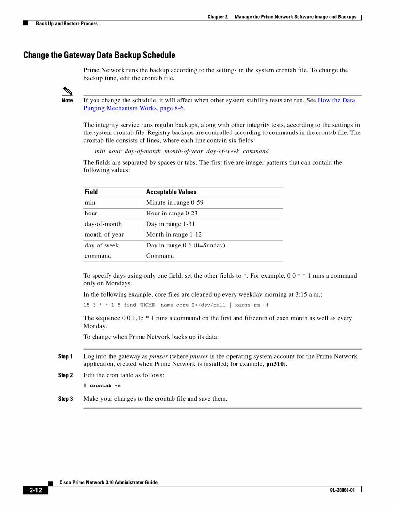
Change the Gateway Data Backup Schedule
Prime Network runs the backup according to the settings in the system crontab file. To change the backup time, edit the crontab file.
Note If you change the schedule, it will affect when other system stability tests are run. See How the Data Purging Mechanism Works, page 8-6.
The integrity service runs regular backups, along with other integrity tests, according to the settings in the system crontab file. Registry backups are controlled according to commands in the crontab file. The crontab file consists of lines, where each line contain six fields:
min hour day-of-month month-of-year day-of-week command
The fields are separated by spaces or tabs. The first five are integer patterns that can contain the following values:
To specify days using only one field, set the other fields to *. For example, 0 0 * * 1 runs a command only on Mondays.
In the following example, core files are cleaned up every weekday morning at 3:15 a.m.:
15 3 * * 1-5 find $HOME -name core 2>/dev/null | xargs rm -f
The sequence 0 0 1,15 * 1 runs a command on the first and fifteenth of each month as well as every Monday.
To change when Prime Network backs up its data:
Step 1 Log into the gateway as pnuser (where pnuser is the operating system account for the Prime Network application, created when Prime Network is installed; for example, pn310).
Step 2 Edit the cron table as follows:
# crontab -e
Step 3 Make your changes to the crontab file and save them.
Field Acceptable Values
min Minute in range 0-59
hour Hour in range 0-23
day-of-month Day in range 1-31
month-of-year Month in range 1-12
day-of-week Day in range 0-6 (0=Sunday).
command Command

2-13Cisco Prime Network 3.10 Administrator Guide
OL-28066-01
Chapter 2 Manage the Prime Network Software Image and Backups Back Up and Restore Process
Perform a Manual Backup of Gateway Data
This procedure explains how to perform an on-demand backup of the Prime Network gateway data. This procedure does not back up any database information. (If you want to perform a manual backup of both gateway and embedded database information, see Perform a Manual Backup of the Embedded Database, page 2-16.) To backup an external Oracle database, see your Oracle documentation; Prime Network does not provide tools to backup an external database.
Step 1 Log into the gateway as pnuser and change the directory to the Main/scripts directory:
# cd $ANAHOME/Main/scripts
Step 2 Start the backup:
# backup.pl backup-folder
Note It is normal for null to appear in response to this command.
Restore Gateway Data
Note To restore an external database, refer to your Oracle documentation.
Use this procedure to restore Prime Network gateway data from a backup. If you have an embedded database, you can restore both the Prime Network data and the embedded database data at the same time using the emdbctl command (see Restore Prime Network Embedded Database Alone or With Gateway Data, page 2-16).
Step 1 Log into the gateway as pnuser.
Step 2 Stop the gateway server and all units:
# cd $ANAHOME/Main# networkctl stop# rall.csh networkctl stop
Step 3 From the NETWORKHOME/Main directory, change to the directory NETWORKHOME/Main/scripts:
# cd NETWORKHOME/Main/scripts
Step 4 Execute the restoration script:
# restore.pl backup-folder
Step 5 Once the restoration is successful, initialize the Prime Network gateway by running the following commands:
# cd Main# networkctl restart

2-14Cisco Prime Network 3.10 Administrator Guide
OL-28066-01
Chapter 2 Manage the Prime Network Software Image and Backups Back Up and Restore Process
Prime Network Embedded Database Backup and RestoreThe Prime Network emdbctl command provides backup and restore tools for deployments with embedded databases. Once you have enabled the backup mechanism, Prime Network backs up the embedded database and gateway data on a regular basis according to your database profile.
Whenever you perform a manual backup of the embedded database using emdbctl, Prime Network also backups up the Prime Network gateway data—that is, registry data, encryption keys, reports, and any other user-specified data stored on the gateway server. If you want to back up only the Prime Network gateway data, see Perform a Manual Backup of Gateway Data, page 2-13.
You can also use the embdctl command to:
• Restore only the embedded database
• Restore the embedded database and gateway data
Note If you have an external database, you must perform the backup as described in your Oracle documentation.
• Enable Embedded Database Backups, page 2-14
• Change the Embedded Database Backup Schedule, page 2-15
• Perform a Manual Backup of the Embedded Database, page 2-16
• Restore Prime Network Embedded Database Alone or With Gateway Data, page 2-16
Enable Embedded Database Backups
When you enabled the backup mechanism for an embedded database deployment, Prime Network schedules automated backups of both the embedded database and gateway data. The emdbctl command will call the backup.pl command to back up the gateway data. Backups are normally enabled during installation, but if you did not enable them, use this procedure to do so. You must enable this mechanism regardless of whether you want will perform backups manually or automatically. You can verify whether the backup mechanism is already enabled by checking the backup directory for recent backups.
Note This procedure requires both Oracle and Prime Network to be restarted.
Before You Begin
The script will prompt you for the following information:
• The destination folders for the backup files and the archive log
• Your database profile.
To enable the backup mechanism for an embedded database deployment:
Step 1 If you did not specify a backup location at installation time, do the following:
a. Create the folders for the backup files and the archive logs.
b. Verify that the OS database user (oracle, by default) has write permission for the folders, or run the following command as the operating system root user:
chown -R os-db-user:oinstall path

2-15Cisco Prime Network 3.10 Administrator Guide
OL-28066-01
Chapter 2 Manage the Prime Network Software Image and Backups Back Up and Restore Process
Step 2 Log into the gateway as pnuser and change the directory to the Main/scripts/embedded_db directory:
# cd $ANAHOME/Main/scripts/embedded_db
Step 3 Start the backup.
# emdbctl --enable_backup
The following is an example of a complete --enable_backup session.
# emdbctl --enable_backup
Reading Prime Network registry- Enter the destination for the backup files:/export/home/oracle/backupYou must create the target destination (path-to-backup-dir) before you continue Verify user oracle has writing permissions on this destination or run the following command as the OS root user: chown -R <database-OS-user>:oinstall <path> Hit the 'Enter' key when ready to continue or 'Ctrl C' to quit- Enter the destination for the archive log: /export/home/oracle/arch- How would you estimate your database profile?-----------------------------------------------1) 1 actionable events per second (POC/LAB deployment)2) Up to 5 actionable events per second3) Up to 20 actionable events per second4) Up to 50 actionable events per second5) Up to 100 actionable events per second6) Up to 200 actionable events per second7) Up to 250 actionable events per second (1 - 7) [default 1] 1Updating Prime Network registryStopping Prime NetworkStopping NCCM DM Server...- DM server is up, about to shut it downStopping AVMs...Done.Configuring the database's automatic backup procedureStarting Prime NetworkStarting MVM........................................Done.
Change the Embedded Database Backup Schedule
Use this procedure to change the embedded database backup time using emdbctl command.
Step 1 Log into the gateway as pnuser and change the directory to the Main/scripts/embedded_db directory:
# cd $ANAHOME/Main/scripts/embedded_db
Step 2 Change the database backup time from 1:00 a.m. (the default) to 3:19 a.m.:
# emdbctl --change_backup_time Reading Prime Network registryConfiguring the DB backup timePlease enter the new hour for the DB Backup (0..23) :3Please enter the new minute for the DB Backup (0..59) :19DB backup time was changed successfully

2-16Cisco Prime Network 3.10 Administrator Guide
OL-28066-01
Chapter 2 Manage the Prime Network Software Image and Backups Back Up and Restore Process
For more information on the embdctl command, see Stop, Start, and Change Embedded Database Settings (embdctl Utility), page 8-18.
Perform a Manual Backup of the Embedded Database
Note If you have an external database, you must perform the backup as described in your Oracle documentation.
This procedure explains how to perform an on-demand backup of a Prime Network embedded database using the emdbctl command. Whenever you use emdbctl to do a manual backup, Prime Network also backs up the Prime Network gateway data—that is, registry data, encryption keys, reports, and any other user-specified data stored on the gateway server (by calling the backup.pl command.) If you want to back up only the Prime Network gateway data, see Perform a Manual Backup of Gateway Data, page 2-13.
Before You Begin
The automatic backup mechanism must be enabled. If you did not enable it during the installation, follow the directions in Enable Embedded Database Backups, page 2-14.
Step 1 Log into the gateway as pnuser and change the directory to the Main/scripts/embedded_db directory:
# cd $ANAHOME/Main/scripts/embedded_db
Step 2 Start the backup:
# emdbctl --backup Reading Prime Network registry Backing up the database Backing up Prime Network
For more information on the embdctl command, see Stop, Start, and Change Embedded Database Settings (embdctl Utility), page 8-18.
Restore Prime Network Embedded Database Alone or With Gateway Data
Note If you have an external database, you must restore data as described in your Oracle documentation.
This procedure explains how to perform an on-demand restore of a Prime Network embedded database using the emdbctl command. When you perform a manual restore using emdbctl, you can restore the database and gateway data (emdbctl --restore), or only the database (emdbctl --restore_db). If you want to restore only the gateway data, see Restore Gateway Data, page 2-13.
If you are going to restore both the database and gateway data, remember that embedded database backups are scheduled according to the database size. They can be restored to any hour within the last 8 days, as described in Table 2-2 on page 2-10. However, Prime Network gateway data is backed up twice a day at 4:00 a.m. and 4:00 p.m and can be restored to only those points in time. (The embdctl command actually calls the backup.pl command to back up gateway data, and the restore.pl command to restore gateway data.) Therefore, find out the time and date of the latest Prime Network data backup, and restoring the data and your database to that time.

2-17Cisco Prime Network 3.10 Administrator Guide
OL-28066-01
Chapter 2 Manage the Prime Network Software Image and Backups Back Up and Restore Process
You do not have to stop Prime Network, the database, or any other processes before performing the restore operation. The script will do this for you. You can use this restore procedure even if the database is down.
Step 1 Log into the gateway as pnuser and change to the directory NETWORKHOME/Main/scripts/embedded_db:
# cd $ANAHOME/Main/scripts/embedded_db
Step 2 Run the restoration script as follows:
# ./emdbctl --restore
This example restores the embedded database and all Prime Network data to the state it was in on May 10, 2012 at 4:00 a.m.
Please enter the date and time information for the restore processRestore year (YYYY) :2012Restore month (1..12) :5Restore day (1..31) :10Restore hour (0..23) :4Restore minute (0..59) :00Selected Restore time (MM-DD-YYYY HH:MI): 05-10-2012 04:00In case of a wrong or impossible date for restore, the DB will be restored to the latest possible point in timeDo you want to continue (Y/N) ?YStopping Prime NetworkStopping AVMs....Done.Restoring the database to 05-10-2012 04:00Successfully restored the database!Restoring Prime NetworkEnter Prime Network's backup directory (the default location is$ANAHOME/backup/date+time): /export/home/pn310/backup/20120510040Checking that the system is down... Prime Network not running on the gateway Backup_dir: /export/home/pn310/backup/201205100400Backing-up current registry to /export/home/pn310/backup_before_restore.jarRestoring registryRestoring to_backupBefore restoring encryption key, backing up last installation encryption keyRestoring encryption keyBefore restoring reports, backing up current reportsRestoring reportsSetting Main/registry ownershipSetting Main/reportfw/rptdocument ownershipDoneWould you like to start Prime Network? (yes,no) [default yes] no
Step 3 Once all of your data is restored, restart the gateway.
Command Restores:
embdctl --restore Embedded database and gateway data
embdctl --restore_db Embedded database only

2-18Cisco Prime Network 3.10 Administrator Guide
OL-28066-01
Chapter 2 Manage the Prime Network Software Image and Backups Track Changes to the Product Image and VNEs
Track Changes to the Product Image and VNEsThe following table shows from where you can get historical information concerning changes to the product image and VNEs.
Information Type Refer to:
Installation-related changes, including changes to VNEs
The appropriate logs. (A complete list of logs is provided in Log Files, page B-3
Backup and restore operations
Detailed Non-Network Events reports (choose Reports > Run Report > Events Reports from main menu).
Licensing events

C H A P T E R
3-1Cisco Prime Network 3.10 Administrator Guide
OL-28066-01
3Manage the Prime Network Components: Gateway, Units, and AVMs
These topics describe the components in the Prime Network system: Gateway, units, AVMs, and VNEs. These topics explain how to check their properties, make changes, and verify their overall health. VNEs are described in greater detail in Configure VNEs and Troubleshoot VNE Problems, page 4-1.
• Prime Network Architecture, page 3-1
• Get Basic Information (Gateway, Unit, AVM, and VNE), page 3-4
• Stop and Restart Prime Network Components, page 3-15
• Manage Client and User Sessions, page 3-20
• Update the Gateway IP Address in Prime Network, page 3-21
• Disable Prime Network Automatic Restarts, page 3-23
• Manage Configurations with Firewalls (Device Proxy), page 3-23
• Configure a Northbound Interface Layer, page 3-26
• Run a Command on All Units, page 3-27
• Delete a Prime Network Unit, page 3-27
• Create and Configure AVMs and Load Balancing, page 3-27
• Check the Overall System and Use the Diagnostics (Graphs Tool), page 3-34
• Track System-Related Events, page 3-43
VNEs are discussed in depth in Configure VNEs and Troubleshoot VNE Problems, page 4-1.
Prime Network ArchitecturePrime Network was designed to handle very large and complex networks. The key to Prime Network scalability is its fully distributed, parallel-processing architecture. Elements in that architecture include Virtual Network Elements (VNEs), Autonomous Virtual Machines (AVMs), gateways, and units. For Figure 3-1 shows the Prime Network architecture.

3-2Cisco Prime Network 3.10 Administrator Guide
OL-28066-01
Chapter 3 Manage the Prime Network Components: Gateway, Units, and AVMs Prime Network Architecture
Figure 3-1 Prime Network Architecture
Gateway Layer
The Prime Network gateway layer includes the gateway server, through which all Prime Network GUI client, OSS, and BSS applications access the Prime Network fabric. Each client connects to its designated gateway. The gateway enforces access control and security for all connections and manages client sessions. It maintains a repository for system settings, topological data, and snapshots of active alarms and events. The gateway also maps network resources to the business context, which enables Prime Network to contain information (such as VPNs and subscribers) that is not directly contained in the network and display it to northbound applications.
The gateway AVM process is AVM 11, which supports the majority of foundation services, including inventory and topology snapshots, VNE communications, authentication, authorization, and accounting (AAA) and administration services, session management, plug-ins, alarms, business objects, maps, and application services.
VNE Layer (Units, AVMs, and VNEs)
The Prime Network VNE layer comprises the interconnected fabric of units, AVMs, and VNEs.
Each unit manages a group of network elements. Units should be distributed in a way that ensures proximity to their network elements. Prime Network also provides a unit server high availability mechanism to protect the system in case a unit malfunctions. Unit availability is established in the gateway as the gateway runs a protection manager process which continuously monitors all units in the
VNEs
Clients
Units
Network
GatewayDatabase
2492
30
3-3Cisco Prime Network 3.10 Administrator Guide
OL-28066-01
Chapter 3 Manage the Prime Network Components: Gateway, Units, and AVMs Prime Network Architecture
network. If the protection manager detects a unit that is malfunctioning, it automatically signals one of the standby servers in its cluster to load the configuration of the faulty unit (from the system registry), and to take over all of its managed network elements. You can designate a unit to act as an active or standby unit when you add it during installation.
AVMs are Java processes that provide the necessary distribution support platform for executing and monitoring multiple VNEs. As Java processes, AVMs have dedicated memory for executing and monitoring multiple VNEs in a distributed manner. AVMs and VNEs are generally distributed among unit servers in the system, but they can also reside together on a Prime Network gateway server.
Some AVMs are reserved, which means they are used by the system; other AVMs are user-created, which means they are used to host devices (VNEs). Prime Network contains a watchdog protocol process that monitors the AVMs, and restarts them if they have stopped. This is called AVM protection.
VNEs are autonomous, miniature engines that operate independently and in parallel. Each VNE is in charge of a single device. It maintains a real-time virtual model of the device, including its physical and logical inventories, and its connectivity references to its immediate neighbors. When a VNE is created, it identifies the NE and begins discovery after receiving the IP address and credentials of the NE. Collectively the VNEs maintain the complete inventory and connectivity information of the network. VNEs share information through peer-to-peer messaging that enables intelligent, scalable, cross-network processing, such as discovering connectivity, end-to-end service tracing, and topology-based correlation and root cause analysis.
It is important to understand the difference between a VNE entity and a device entity in Prime Network.
• Device entities are displayed on maps in the Vision GUI client. From here you can view the device physical and logical inventory, and network-related connections.
• VNE entities are displayed in the Administration GUI client. A VNE entity in the Administration GUI client corresponds to a device entity shown on a Vision map. From the Administration GUI client you can check a VNE to see if there are any communication or modeling issues between the VNE and the device it represents.
Managing the network through a fabric of autonomous VNEs ensures scalability by avoiding any single computational bottleneck; it enables the Prime Network platform to grow along with the network. VNEs divide the network into modular self-contained blocks. The VNE layer accommodates network changes by adding or upgrading VNEs whenever network changes occur.
Essentially, the unit VNE fabric builds a virtual shadow of the real network, as shown in Figure 3-2.

3-4Cisco Prime Network 3.10 Administrator Guide
OL-28066-01
Chapter 3 Manage the Prime Network Components: Gateway, Units, and AVMs Get Basic Information (Gateway, Unit, AVM, and VNE)
Figure 3-2 VNEs Create a Model of the Network
Get Basic Information (Gateway, Unit, AVM, and VNE)These topics explain how you can get the properties and current status of the Prime Network components:
• Get Gateway Status and Property Information, page 3-5
• Get Unit Status and Property Information, page 3-6
• Get AVM Status and Property Information (Including Reserved AVMs), page 3-8
• Get VNE Status and Property Information, page 3-12
Physical network
Each device is representedin the Prime Network modelby its VNE
Network model built by unit VNE fabric
3452
44

3-5Cisco Prime Network 3.10 Administrator Guide
OL-28066-01
Chapter 3 Manage the Prime Network Components: Gateway, Units, and AVMs Get Basic Information (Gateway, Unit, AVM, and VNE)
Get Gateway Status and Property InformationThe best practice for getting gateway information is to right-click the gateway in the navigation area and select Properties, as shown in Figure 3-3. The log for the gateway process is stored in NETWORKHOME/Main/logs/11.out.
Figure 3-3 Gateway Status and Properties
Column Description
Name Name of gateway.
IP Address The IP address of the gateway as defined in Prime Network Administration.
Status The status of the gateway.
Up Since The date and time when the gateway was last loaded.
Physical Memory The total physical memory on the gateway (both free and in use).
Physical Memory Available
Of the total physical memory on the gateway, amount of memory that has not been assigned to any AVMs.

3-6Cisco Prime Network 3.10 Administrator Guide
OL-28066-01
Chapter 3 Manage the Prime Network Components: Gateway, Units, and AVMs Get Basic Information (Gateway, Unit, AVM, and VNE)
Get Unit Status and Property InformationUnits are created during the installation process as described in the Cisco Prime Network 3.10 Installation Guide. Like the gateway, the best practice for getting unit information is to right-click a unit in the navigation area and select Properties. Figure 3-4 provides an example of unit properties.
Total Memory Assigned All AVMs
The total physical memory apportioned to all AVMs on the gateway (both user-created and reserved), regardless of whether the AVMs are up or down. This figure does not reflect the memory that is in use (that figure is represented by Allocated Memory Up AVMs). This total includes the additional 35% memory the operating system adds to the AVM size when the AVM is created. (See Add AVMs, page 3-28).
Total Memory Assigned Up AVMs
The total physical memory apportioned to Up AVMs on the gateway (both user-created and reserved AVMs). This figure does not reflect the memory is in use (that figure is represented by Allocated Memory Up AVMs). It includes the additional 35% memory the operating system adds to the AVM size when the AVM is created. (See Add AVMs, page 3-28).
Allocated Memory Up AVMs
The total physical memory being used by Up AVMs on the gateway (both user-created and reserved AVMs).
Protection Group The cluster group that the gateway belongs to as part of the unit high availability mechanism and cannot be modified. If any units in the cluster go down, a standby unit will take over. By default, the gateway is assigned to the default-pg protection group.
Enable Unit Protection Indicates that the gateway is using AVM protection and unit server high availability. These are the mechanism that ensure redundancy. They cannot be modified. See Overview of Unit and Process Protection, page 5-1.
Column Description

3-7Cisco Prime Network 3.10 Administrator Guide
OL-28066-01
Chapter 3 Manage the Prime Network Components: Gateway, Units, and AVMs Get Basic Information (Gateway, Unit, AVM, and VNE)
Figure 3-4 Unit Status and Properties
Table 3-1 Unit Properties
Field Description
Name Name of the unit server.
IP Address The IP address of the unit server. Units behind firewalls or NAT devices will have an IP address of 0.0.0.#. This is an artificial IP address used by the gateway server.
Status Up The unit process is reachable, was loaded, and has started.
Down The unit is reachable, but was stopped. This is the status when an networkctl stop command is issued. The unit is both operationally and administratively down.
Unreachable The unit cannot be reached by the gateway, so it cannot be managed.
Disconnected The unit was disconnected from the gateway (normally a temporary measure to address a problem). See Stop Unit Communication with the Gateway (Disconnect), page 3-17.
Up Since The date and time that the unit was last started.
Physical Memory The total physical memory on the unit (both free and in use).
Physical Memory Available
Of the total physical memory on the unit, amount of memory that has not been assigned to any AVMs.

3-8Cisco Prime Network 3.10 Administrator Guide
OL-28066-01
Chapter 3 Manage the Prime Network Components: Gateway, Units, and AVMs Get Basic Information (Gateway, Unit, AVM, and VNE)
Get AVM Status and Property Information (Including Reserved AVMs)When you select a gateway server or unit in the navigation tree, Prime Network displays all of its member AVMs. This includes reserved AVMs and user-created AVMs.
Reserved AVMs
Reserved AVMs are created by Prime Network and used for backend purposes. These AVMs cannot be edited or deleted. Some reserved AVMs are only installed on the gateway; others are installed on both the gateway and units. For example, in Figure 3-6, the gateway server has ten system and user-created AVMs.
Total Memory Assigned All AVMs
The total physical memory apportioned to all AVMs (both user-created and reserved), regardless of whether the AVMs are up or down. This figure does not reflect the memory that is in use by AVMs (that figure is represented by Allocated Memory Up AVMs). This total includes the additional 35% memory the operating system adds to the AVM size when the AVM is created. (See Add AVMs, page 3-28).
Total Memory Assigned Up AVMs
The total physical memory apportioned to Up AVMs (both user-created and reserved). This figure does not reflect the memory is in use (that figure is represented by Allocated Memory Up AVMs). It includes the additional 35% memory the operating system adds to the AVM size when the AVM is created. (See Add AVMs, page 3-28).
Allocated Memory Up AVMs
The total physical memory being used by Up AVMs (both user-created and reserved AVMs).
Protection Group If checked, the unit is using unit server high availability. The Protection Group drop-down lists shows the cluster that the unit belongs to. If any units in the cluster go down, a standby unit will take over. By default, all units are assigned to the default-pg protection group.
Enable Unit Protection
Indicates that the gateway is using AVM protection and unit server high availability. These are the mechanism that ensure redundancy. This should always be enabled. See Overview of Unit and Process Protection, page 5-1.
Table 3-1 Unit Properties (continued)
Field Description

3-9Cisco Prime Network 3.10 Administrator Guide
OL-28066-01
Chapter 3 Manage the Prime Network Components: Gateway, Units, and AVMs Get Basic Information (Gateway, Unit, AVM, and VNE)
Figure 3-5 Listing all AVMs in a Unit or Server
Table 3-2 lists the AVMs that are reserved by Prime Network. You can check the status of these AVMs either using the GUI client or networkctl.
Table 3-2 Reserved AVMs
AVM # Purpose
Is installed on...Can be checked using1...
GW Unit GUI networkctl
AVM 0 High Availability/Switch AVM—Enables communication between the unit and other units, as well as the gateway. See Manage Redundancy for Units and Processes, page 5-1.
X X — X
AVM 11 Gateway AVM—Manages the gateway server and other processes running on it. See Manage the Prime Network Components: Gateway, Units, and AVMs, page 3-1.
X — — X
AVM 19 Auto-Add AVM—Used by auto-add mechanism. See How VNE Auto-Add Works, page 4-13.
X — — X
AVM 25 Fault Agent AVM—Processes event information (in each unit), including updates and new correlation information, and generates new tickets when required. See Control Event Monitoring, page 9-1.
X X X X
AVM 35 Service Discovery AVM—Performs Carrier Ethernet service discovery (for example, EVC). For large-scale deployments with many services, the memory for AVM 35 can be increased. (For information on how to do this and other capacity planning tasks, contact your Cisco account representative.)
X — — X
AVM 66 Workflow engine AVM—Defines rules and dependencies to activate business and network processes. See Manage Workflows, Command Scripts, and Activations, page 10-1.
X — X X
AVM 76 Job scheduler AVM/. X — X X

3-10Cisco Prime Network 3.10 Administrator Guide
OL-28066-01
Chapter 3 Manage the Prime Network Components: Gateway, Units, and AVMs Get Basic Information (Gateway, Unit, AVM, and VNE)
AVM Properties
If you select All Servers and click the All AVMs tab, Prime Network displays all of the user-created AVMs in the entire system. For example, in Figure 3-6, the entire system has 10 user-created AVMs.
Figure 3-6 Listing all User-Created AVMs in Prime Network
The fields in the AVM table are described in Table 3-1. To see which fields are editable, right-click an AVM and select properties (refer to Table 3-4).
AVM 77 Reserved for use by Prime Network Change and Configuration Management (when installed).
X — X X
AVM 78 VNE topology AVM—Distributes topology information among VNEs. X X — X
AVM 83 TFTP Server—Reserved for use by Prime Network Change and Configuration Management (when installed) if using TFTP.
X X — X
AVM 84 Reports AVM—Manages the reporting framework. X — — X
AVM 99 Management AVM—Manages the unit and the other AVMs running on the unit (or gateway, if there are no separate units).
X X — X
AVM 100 Event Collector AVM—Listens for and receives traps and syslog notifications from devices, and forwards them to corresponding VNEs. See Control Event Monitoring, page 9-1.
X X X X
1. You can also check AVM status using the system health and diagnostics tool; see Check the Overall System and Use the Diagnostics (Graphs Tool), page 3-34.
Table 3-2 Reserved AVMs (continued)
AVM # Purpose
Is installed on...Can be checked using1...
GW Unit GUI networkctl

3-11Cisco Prime Network 3.10 Administrator Guide
OL-28066-01
Chapter 3 Manage the Prime Network Components: Gateway, Units, and AVMs Get Basic Information (Gateway, Unit, AVM, and VNE)
Table 3-3 AVM Properties in AVMs List
Field Description
ID The AVM ID. This cannot be changed once the AVM is created.
If Prime Network created the AVM using auto-add, it used the first available 3-digit number starting at 101.
Status Starting Up When a Start (command) option is issued.
Up The AVM process is reachable, was loaded, and has started. This is the status when the AVM is created (and you selected Activate Upon Creation), and no problems are encountered.
Shutting Down When a Stop (command) option is issued and, while the command is being run, some processes are still running, the status of the AVM is Shutting Down.
Down The AVM process is reachable, but was stopped. This is the status when a Stop (command) is issued. The AVM is both operationally and administratively down.
Unreachable The AVM process cannot be reached by the gateway, so the AVM cannot be managed.
Disconnected The AVM is on a unit that was disconnected from the gateway (the unit has a Disconnected status).
Unit Data IP Address IP address of the parent unit server. Units behind firewalls or NAT devices will have an IP address of 0.0.0.#. This is an artificial IP address used by the gateway server.
Available Memory
The amount of memory that is currently available on the parent unit (note time stamp).
Allocated Memory
The total physical memory being used by the AVM. This field is editable but changing it requires an AVM restart to apply the change.
Total Memory Assigned
The total physical memory assigned to the AVM when it was created. (The operating system adds an additional 35% to the AVM size. This additional memory is used by the operating system for backend tasks, leaving the desired amount of memory for use by VNEs.)
Key The name of the AVM as defined in Prime Network. The key uniquely identifies an AVM in the Prime Network system, across all units, thus enabling a transparent failover scenario in the system. Note that the key can be different from the ID (AVM number); the ID is listed in the AVMs table when you select the parent unit or gateway server. This field is editable but requires an AVM restart.
Auto-added AVMs
AVM ID (unit-ip)
Manually created AVMs
AVMID_nnn (where nnn is a unique designator assigned by Prime Network)

3-12Cisco Prime Network 3.10 Administrator Guide
OL-28066-01
Chapter 3 Manage the Prime Network Components: Gateway, Units, and AVMs Get Basic Information (Gateway, Unit, AVM, and VNE)
If you right-click a specific AVM and choose Properties, you can view the following additional details the AVMs. If you edit any fields, you must restart the AVM to apply your changes.
When moving an AVM, its status has a bearing on whether the process is automatically restarted. If its status is Up, it is restarted; if its status is down, it is not restarted. For more information about moving AVMs, see Move and Delete AVMs, page 3-33.
You can also get AVM diagnostic information using the system health and diagnostics tool. The tool provides a drill down feature so you can check user-defined AVMs health, errors or exceptions, and GC prints. See Check the Overall System and Use the Diagnostics (Graphs Tool), page 3-34.
Get VNE Status and Property InformationVNEs are the central building blocks of the Prime Network system. Each VNE is an autonomous, miniature engine that is in charge of a single device. But a VNE is an entity that only exists within Prime Network; the real device is a separate entity. These topics explain how to get basic status and property information for a VNE.
The VNE process must be completely functional in order for Prime Network to properly model and monitor a device. This administrative condition of the VNE is expressed through the VNE status.
For information on VNE investigation, modeling, and communication, and how to add or change VNEs, see Configure VNEs and Troubleshoot VNE Problems, page 4-1.
Memory Consumption
Indicates whether the AVM has surpassed its warning memory consumption warning threshold. Supported values are:
N/A The AVM is a system AVM; memory consumption is not applicable.
Normal The AVM is within normal memory consumption.
High The AVM has exceeded its threshold and you should adjust its load. See Update the Gateway IP Address in Prime Network, page 3-21.
Table 3-3 AVM Properties in AVMs List (continued)
Field Description
Table 3-4 Enable AVM Protection
Field Description
Enable AVM Protection
If the check box is checked, AVM protection (the watchdog protocol) is enabled. For more information, see Chapter 5, “Manage Redundancy for Units and Processes”.
Note It is highly recommended that you do not disable this option if unit server high availability is enabled. If you change the option when the AVM is up, you must disable and re-enable the AVM for the change to take effect.
This field is editable.
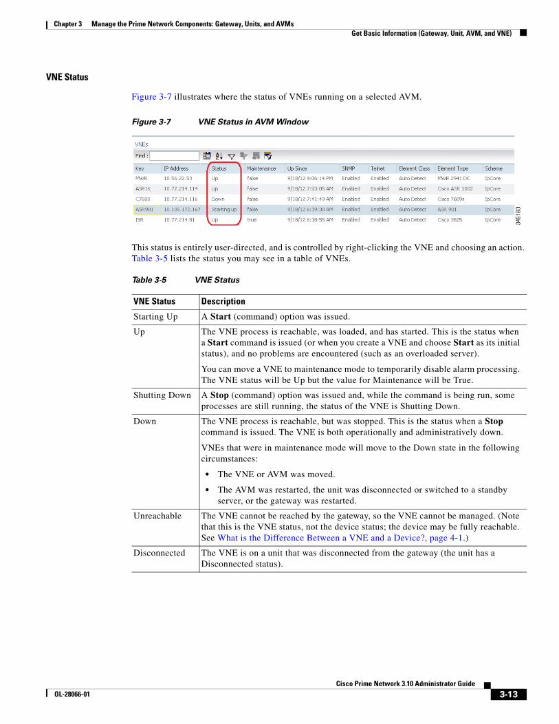
3-13Cisco Prime Network 3.10 Administrator Guide
OL-28066-01
Chapter 3 Manage the Prime Network Components: Gateway, Units, and AVMs Get Basic Information (Gateway, Unit, AVM, and VNE)
VNE Status
Figure 3-7 illustrates where the status of VNEs running on a selected AVM.
Figure 3-7 VNE Status in AVM Window
This status is entirely user-directed, and is controlled by right-clicking the VNE and choosing an action. Table 3-5 lists the status you may see in a table of VNEs.
Table 3-5 VNE Status
VNE Status Description
Starting Up A Start (command) option was issued.
Up The VNE process is reachable, was loaded, and has started. This is the status when a Start command is issued (or when you create a VNE and choose Start as its initial status), and no problems are encountered (such as an overloaded server).
You can move a VNE to maintenance mode to temporarily disable alarm processing. The VNE status will be Up but the value for Maintenance will be True.
Shutting Down A Stop (command) option was issued and, while the command is being run, some processes are still running, the status of the VNE is Shutting Down.
Down The VNE process is reachable, but was stopped. This is the status when a Stop command is issued. The VNE is both operationally and administratively down.
VNEs that were in maintenance mode will move to the Down state in the following circumstances:
• The VNE or AVM was moved.
• The AVM was restarted, the unit was disconnected or switched to a standby server, or the gateway was restarted.
Unreachable The VNE cannot be reached by the gateway, so the VNE cannot be managed. (Note that this is the VNE status, not the device status; the device may be fully reachable. See What is the Difference Between a VNE and a Device?, page 4-1.)
Disconnected The VNE is on a unit that was disconnected from the gateway (the unit has a Disconnected status).

3-14Cisco Prime Network 3.10 Administrator Guide
OL-28066-01
Chapter 3 Manage the Prime Network Components: Gateway, Units, and AVMs Get Basic Information (Gateway, Unit, AVM, and VNE)
VNE Properties
VNEs can have a wide range of properties depending on how they were created. When a VNE is created, it identifies the NE by vendor, device family, device subfamily, device type and software version. Once the NE type is determined, the VNE begins discovery after receiving the IP address and credentials of a specific NE. It collects the basic inventory of the system, both physical and logical, and attempts to determine its place in the network topology.
You can get a wide range of information about a VNE by choosing its host AVM and looking at the VNEs table. Figure 3-8 shows an example of an AVM’s VNEs table in the Administration GUI client.
Figure 3-8 List of VNEs in AVM Window
Column Description
Key The VNE name.
IP Address The IP address of the device as defined in Prime Network Administration.
Status Status of the VNE: Starting Up, Up, Shutting Down, Down, or Unreachable.
Maintenance Indicates whether the VNE is (true) or is not (false) in maintenance mode.
Up Since Date and time that the VNE was last started.
SNMP Indicates whether SNMP is enabled (true) or disabled (false) on the VNE.
Telnet Indicates whether Telnet is enabled (true) or disabled (false) on the VNE.
Element Class VNE category, such as Auto Detect, Generic SNMP, Cloud, or ICMP.
Element Type Device type (manufacturer name), such as Cisco 7204.
Scheme Determines what data should be retrieved for each device, and which commands and protocols Prime Network should use to collect that data.
Polling Group The name of the polling group. The entry in this column is blank if the polling group is an instance.
Unit Name of the parent unit.
Version Version of the VNE device driver that the VNE is currently using.
Device Package Name
Device Package that is installed on the gateway server. You can use this and the driver file name information to verify whether a newer driver is available, which might supply additional functionality.
Driver File Name
VNE device driver that is currently being used by the VNE.

3-15Cisco Prime Network 3.10 Administrator Guide
OL-28066-01
Chapter 3 Manage the Prime Network Components: Gateway, Units, and AVMs Stop and Restart Prime Network Components
To retrieve all of a VNE’s properties, launch its Properties dialog. Figure 3-9 illustrates a VNE properties dialog.
Figure 3-9 VNE Properties
All of the VNE properties are described in detail in VNE Properties Reference, page D-1. For information on how to add, manage, delete, and troubleshoot VNEs, see Configure VNEs and Troubleshoot VNE Problems, page 4-1.
Stop and Restart Prime Network ComponentsIf you stop and restart the gateway server, you stop all active queries, flows, and transactions being run on the gateway, all units, all AVMs, and all VNEs. If you make changes to a component, such as an AVM, you normally only have to restart the individual component to apply your changes. If you install a new VNE driver, you only need restart the VNE, not the hosting AVM.

3-16Cisco Prime Network 3.10 Administrator Guide
OL-28066-01
Chapter 3 Manage the Prime Network Components: Gateway, Units, and AVMs Stop and Restart Prime Network Components
Note By default, Prime Network automatically restarts when the gateway server is rebooted. To disable this behavior, see Disable Prime Network Automatic Restarts, page 3-23.
If you need to restart Prime Network but want to restart AVMs in a controlled manner, see Restart Prime Network In a Gradual Manner, page 3-18.
Table 3-6 Impact of Stopping a Prime Network Component
Stopping this component... ...Stops all active queries, flows, and transactions on:
To stop or change a component’s status, see:
VNEs The single VNE. It may affect NEs to which it is connected. You can restart a VNE from the GUI client.
Stop, Start, and Move VNEs to Maintenance Mode, page 4-9
AVMs The AVM, and all VNEs hosted by the AVM. You can restart an AVM from the GUI client. All VNEs in Maintenance mode are moved to Down.
Change AVM Status (Start or Stop), page 3-33
Units The unit, all AVMs hosted by the unit, and all VNEs hosted by the AVMs. All VNEs in Maintenance mode are moved to Down.
This action may cause VNEs to be reported as unreachable until the handshake protocols are complete. Upon restart, all AVMs are restarted at the same time which can be a resource-intensive operation. Consider gradually restarting all AVMs using the Administration GUI client. If you need more control, you can configure AVMs to not restart when the unit is restarted.
Stop Unit Communication with the Gateway (Disconnect), page 3-17
or
Restart Prime Network In a Gradual Manner, page 3-18
Gateway The gateway, all units hosted by the gateway, all AVMs hosted by the units, and all VNEs hosted by the AVMs. All VNEs in Maintenance mode are moved to Down.
Same impact as for units, times the number of units in the system.
Note If you are using gateway server high availability, start and stop the gateway using the appropriate application or CLI commands, not networkctl. Stopping the applications using the regular application commands without the awareness of the cluster software can cause the service group to failover.
Use networkctl to Stop and Start Components, page 3-19
or
Restart Prime Network In a Gradual Manner, page 3-18

3-17Cisco Prime Network 3.10 Administrator Guide
OL-28066-01
Chapter 3 Manage the Prime Network Components: Gateway, Units, and AVMs Stop and Restart Prime Network Components
Stop Unit Communication with the Gateway (Disconnect)Disconnecting a unit allows you to temporarily stop unit-gateway communication so you can fix the unit problem without having to reinstall the unit when you are done (units can only be added using the installation script). For example, say a unit’s Ethernet card goes down and the unit becomes unreachable. You could do the following:
1. Disconnect the unit from the gateway, and move all AVMs and VNEs to a temporary unit.
2. Fix the Ethernet card problem.
3. Reconnect the unit to the gateway.
4. Move all AVMs and VNEs back to the unit.
As this scenario shows, even if a unit is in the Disconnected state, you can still, add, delete, start, stop, and update AVMs and VNEs on the unit.
Disconnecting a unit that is part of a protection group does not trigger starting the standby unit because unit protection is also disabled on the active unit that is being disconnected. Prime Network will not allow you to disconnect a unit that is the designated standby unit.
Reconnecting the unit restarts the unit and all AVMs and VNEs. Unit information is uploaded to the gateway server, and registry information is downloaded to the unit from the gateway.
Note Before you disconnect a unit, if the Event Collector (AVM 100) is enabled on the unit, enable an Event Collector on another unit or the system will drop events. You must configure devices to forward events to the new Event Collector, and enable AVM 100 on another unit, as described in Enabling a New Event Collector on a Unit, page 9-12.
To disconnect a unit:
Step 1 In the Prime Network Administration window, select All Servers.
Step 2 Right-click the unit and choose Disconnect.
Step 3 If the unit is running, a warning will be displayed that says
Step 4 Confirm your choice. You can now delete the unit as described in Delete a Prime Network Unit, page 3-27.
Similarly, if you want to reconnect a unit, right-click the unit and choose Connect.

3-18Cisco Prime Network 3.10 Administrator Guide
OL-28066-01
Chapter 3 Manage the Prime Network Components: Gateway, Units, and AVMs Stop and Restart Prime Network Components
Restart Prime Network In a Gradual Manner
Note If you are using gateway server high availability, start and stop the gateway using the Veritas Cluster Manager application or CLI commands, not networkctl. Stopping the applications using the regular application commands without the awareness of the cluster software can cause the service group to failover.
When you use the networkctl start or restart command, all user-defined AVMs (AVMs containing VNEs) start at the same time. This can be a resource-intensive operation on a very loaded system. It can also cause unwanted side effects for systems with an external authentication server (such as TACACS). In such cases, it is better to gradually start all AVMs.
If the Prime Network system is running, you can use the Prime Network Administration GUI to bring up AVMs one by one. However, because the AVMs normally restart in a manner of minutes, this method may not give you the control you want. You can reconfigure AVMs to not restart when the system is restarted. Then you can start the AVMs manually, once Prime Network Administration is running.
Disable the user-defined AVMs on each unit, as follows.
Note Changes to the registry should only be carried out with the support of Cisco. For details, contact your Cisco account representative.
Before You Begin
Prepare a list of the AVMs you do not want to automatically restart, and the IP addresses of the units that are hosting the AVMs.
Step 1 Log into the gateway as pnuser (where pnuser is the operating system account for the Prime Network application, created when Prime Network is installed; an example of pnuser is pn310).
Step 2 Change to the Main directory by entering the following command:
# cd $ANAHOME/Main
Step 3 For each AVM you do not want to auto-restart, change the registry key named enable to false using the runRegTool.sh script:
• For user-created AVMs that are hosted by the gateway server, use the following command:
runRegTool.sh -gs gateway-IP set 127.0.0.1 “avm99/services/bsm/avm-id/enable” false
In this example, the AVM ID is 207 and is hosted by the gateway:
# ./runRegTool.sh -gs 127.0.0.1 set 127.0.0.1 "avm99/services/bsm/avm207/enable" false
• For user-created AVMs that are hosted by another unit, use the following command:
runRegTool.sh -gs gateway-IP set unit-IP “avm99/services/bsm/avm-id/enable” false
In this example the AVM is AVM 30, and it is hosted by a unit with the IP address 172.23.240.12:
# ./runRegTool.sh -gs 127.0.0.1 set 172.23.241.12 "avm99/services/bsm/avm301/enable" false

3-19Cisco Prime Network 3.10 Administrator Guide
OL-28066-01
Chapter 3 Manage the Prime Network Components: Gateway, Units, and AVMs Stop and Restart Prime Network Components
Step 4 When you have finished reconfiguring the AVMs, restart the gateway:
# cd $ANAHOME/Main # networkctl restart
Step 5 Gradually start the individual AVMs using the Prime Network Administration GUI (see Change AVM Status (Start or Stop), page 3-33).
Note You should monitor the unit’s CPU usage while starting an AVM, and only start additional AVMs when the unit CPU usage is stable.
Use networkctl to Stop and Start Components
Note By default, Prime Network automatically restarts if the gateway is rebooted. To disable this behavior, see Disable Prime Network Automatic Restarts, page 3-23.
You can use the networkctl command to check the status of all unit processes (including user-created AVMs). Restarting a unit stops all AVM and VNE processes on the unit, and then restarts them. Because system saves information within the process memory, restarting a unit causes some of the information to disappear. Therefore, recovering all information that was stored in the process memory prior to the restart takes as long as the longest full system polling cycle. Data that was persisted (stored in the unit) is available immediately. (Persistency is described in Change Settings That Control VNE Data Saved After Restarts, page 12-36.
Keep these items in mind when restarting a unit:
• Some of the VNEs running on the unit will be reported as unreachable.
• All active queries, flows, and transactions that are currently being run within the unit’s VNEs are stopped.
To start or restart a unit:
Step 1 Log into the unit server as pnuser and change to the Main directory:
# cd $ANAHOME/Main
Step 2 Enter the following, substituting start or restart for option:
# networkctl option
The unit begins loading. The process might take a while to complete.
For more information on working with AVMs and understanding their status, see Get AVM Status and Property Information (Including Reserved AVMs), page 3-8.

3-20Cisco Prime Network 3.10 Administrator Guide
OL-28066-01
Chapter 3 Manage the Prime Network Components: Gateway, Units, and AVMs Manage Client and User Sessions
Manage Client and User SessionsThese topics explain how to use the Session Manager GUI to monitor and terminate user sessions, how to set a system-wide idle time for all client sessions, and how to configure the maximum number of client sessions that can be open at one time.
• Monitor and Terminate User Sessions, page 3-20
• Configure Session Idle Times and Maximum System-Wide Sessions, page 3-20
Monitor and Terminate User Sessions
The Session Manager GUI helps you manage all Prime Network GUI and NBI client sessions. You can terminate sessions and ask users to log back in, or just kill sessions completely. The Session Manager uses the HTTPS protocol and authentication method.
To open the Session Manager, enter https://gateway_ip:6081/ana/services/session_mgr in your browser where gateway_ip is the gateway IP address. The Session Manager lists the following information about currently open sessions for that gateway.
Configure Session Idle Times and Maximum System-Wide Sessions
By default, the Prime Network gateway will not disconnect GUI client sessions regardless of how long the session has been inactive. You change this behavior and set a client inactivity timer if needed.
In addition, you can control the maximum number of clients, system-wide, that can connect to a gateway at one time. Once this number is exceeded, the gateway will refuse client connections. By default this is set to 150 connections. (User accounts also have a setting for limiting connections per user.)
Table 3-7 Information Displayed by Session Manager
Field Description
Session ID Session identifier (internal).
Application Prime Network client application being used: Prime Network Vision, Prime Network Manage (Administration), or eventvision (Prime Network Events). No application is listed for the NBI.
Client Type Prime Network client type being used: STLS (web), bql (BQL NBI), or app (application).
User ID User identifier (internal).
Username Name of user that is logged into the session.
Client ID Client identifier (internal).
CAS If true, indicates that the user authentication was performed by Central Authentication Server (the user navigated to the Session Manager from a ticket or from a Cisco Prime Central installation).
Manage Tools for administering the session:
• kill terminates the session.
• ask login terminates the session and requests that the user log back in (users will see a popup message with this information).

3-21Cisco Prime Network 3.10 Administrator Guide
OL-28066-01
Chapter 3 Manage the Prime Network Components: Gateway, Units, and AVMs Update the Gateway IP Address in Prime Network
The registry entry and default value are provided in Table 3-8.
Note Do not exceed the value of 150 maximum open sessions. Doing so can negatively impact system performance.
This example changes the client session idle time to 30 minutes. When 30 minutes are exceeded, the gateway will automatically disconnect the idle clients.
Step 1 Log into the gateway as pnuser and change to the Main directory by entering the following command.
# cd $ANAHOME/Main
Step 2 To change the client inactivity timer, use this command. In this example the timer is changed to 30 minutes:
# ./runRegTool.sh -gs gateway-IP set 127.0.0.1 "avm11/services/sessionmanager/sessionIdleTime" 1800000
Update the Gateway IP Address in Prime Network
Note This feature is only supported on configurations that meet both of the following criteria:
• The gateway and unit are installed on the same server.
• The system is running Linux and has an embedded database.
It is not supported on configurations with units installed on separate servers.
If the IP address of the gateway server is changed, you must also change several items in the registry so that system components can continue to communicate properly. Prime Network provides a script called change_gw_ip.pl that updates the following registry files:
• avm66.xml—Changes the database path entry
• persistency.xml—Changes the entries for the main database and Event Archive database schemas.
• avm0.xml—Changes the uplink entry between the gateway and its units.
The script will also restart all units to update the units with the new gateway information. The script also makes the changes that are required when using Prime Network Change and Configuration Management.
Table 3-8 Registry Setting for Gateway Open Sessions
Registry Entry Description Default Value
sessionIdleTime Client inactivity timer; when exceeded, the gateway should close the connection with a client (in milliseconds)
0
maxOpenSessions Maximum number (system-wide) of sessions that may be open with the gateway (includes both GUI client and BQL sessions)
150

3-22Cisco Prime Network 3.10 Administrator Guide
OL-28066-01
Chapter 3 Manage the Prime Network Components: Gateway, Units, and AVMs Update the Gateway IP Address in Prime Network
Before You Begin
• Make sure you have the old and new IP addresses for the gateway server.
• Re-configure the devices to forward events to the new IP address of the gateway server if the Cisco Event Listener (AVM 100) is enabled and is running on the gateway server.
To update the registry with the new IP address of the gateway:
Step 1 Stop all applications that are running on the gateway server.
• For an embedded database, log in as the Oracle user and run the following commands:
# cd $ANAHOME/Main/scripts/embedded_db#./emdbctl--stop
• For an external database:
# cd $ANAHOME/Main# networkctl stop
Step 2 If you have an external database, stop the database process. (For embedded databases, this step is not required because the internal database is stopped by the command used in Step 1.)
Step 3 Confirm that the database is stopped. If it is not, login in as the database user and issue the following command:
ORACLE_HOME/product/product-version/db_1/bin/dbshut
Step 4 Start the change_gw_ip.pl script as follows:
# cd $ANAHOME/Main/scripts# change_gw_ip.pl
In the following example, the old IP address is 10.56.57.50, the new IP address is 10.56.22.47, and 10.56.56.111 is the IP address of the unit that is connected to the gateway.
This action can only be performed after Oracle DB and OS were updated. Continue? (y/n): yPlease enter the old IP Address: 10.56.57.50Please enter the new IP Address: 10.56.22.47Updated: /export/home/pn310/Main/registry/persistency.xmlUpdated: /export/home/pn310/Main/registry/ConfigurationFiles/0.0.0.0/persistency.xmlUpdated: /export/home/pn310/Main/registry/ConfigurationFiles/127.0.0.1/persistency.xmlUpdated: /export/home/pn310/Main/registry/ConfigurationFiles/avm66.xmlUpdated: /export/home/pn310/Main/registry/ConfigurationFiles/avm0.xmlUpdated: /export/home/pn310/Main/registry/ConfigurationFiles/10.56.56.111/persistency.xmlUpdated: /export/home/pn310/Main/registry/ConfigurationFiles/10.56.56.111/avm0.xmlUpdated: /export/home/pn310/Main/registry/ConfigurationFiles/10.56.56.111/avm99.xmlUpdating units...
Step 5 If you want to undo the changes (by not restarting the gateway), cancel the procedure as follows:
ANA GW and units are about to be restarted. Continue? (y/n): nWould you like to undo the changes? (y/n): yStopping Units...Updated: /export/home/pn310/Main/registry/persistency.xmlUpdated: /export/home/pn310/Main/registry/ConfigurationFiles/0.0.0.0/persistency.xmlUpdated: /export/home/pn310/Main/registry/ConfigurationFiles/127.0.0.1/persistency.xmlUpdated: /export/home/pn310/Main/registry/ConfigurationFiles/avm66.xmlUpdated: /export/home/pn310/Main/registry/ConfigurationFiles/avm0.xmlUpdated: /export/home/pn310/Main/registry/ConfigurationFiles/10.56.56.111/persistency.xmlUpdated: /export/home/pn310/Main/registry/ConfigurationFiles/10.56.56.111/avm0.xmlUpdated: /export/home/pn310/Main/registry/ConfigurationFiles/10.56.56.111/avm99.xmlUpdating units...Done.

3-23Cisco Prime Network 3.10 Administrator Guide
OL-28066-01
Chapter 3 Manage the Prime Network Components: Gateway, Units, and AVMs Disable Prime Network Automatic Restarts
Step 6 If you want to commit the changes and restart the units and gateway, proceed as follows:
ANA GW and units are about to be restarted. Continue? (y/n): yStopping Units...executing: ssh 10.56.56.111 networkctl stopStopping AVMs...done.Restarting GW...Stopping AVMs...done.Starting MVM...............................................Done.Starting Gateway.................................................................Done.
Step 7 Verify that Prime Network is running properly:
# cd $ANAHOME/Main# networkctl status
Step 8 Verify that the Oracle database is running properly using your preferred method.
Disable Prime Network Automatic RestartsBy default, the Prime Network will automatically start whenever the gateway server is rebooted. If you wish to disable this feature, run the following procedure from the gateway. The change will be populated to all units in the system.
Step 1 Log into the gateway as pnuser and change to the Main directory.
# cd $ANAHOME/Main
Step 2 Issue this command to disable Prime Network from starting when the server is rebooted:
# ./runRegTool.sh -gs 127.0.0.1 set 0.0.0.0 "site/system/startup" false
(If you want to re-enable this feature, specify true.)
The change is automatically applied; you do not need to restart the gateway.
Manage Configurations with Firewalls (Device Proxy)Prime Network can manage gateways, units, and devices that are behind firewalls, as long as the system is configured as described in this topic.
Servers and Units Behind Firewalls
If a gateway server is behind a firewall, you must open ports on the firewall. The gateway will to need publicly addressable IP address.
If any unit servers are located behind firewalls or NAT devices:
• The unit is displayed in Prime Network Administration GUI client with an IP address of 0.0.0.#. This is an artificial IP address used by the gateway server.
• You do not have to open special ports for the units. The units will always initiate communications.

3-24Cisco Prime Network 3.10 Administrator Guide
OL-28066-01
Chapter 3 Manage the Prime Network Components: Gateway, Units, and AVMs Manage Configurations with Firewalls (Device Proxy)
• An Event Collector (AVM 100) must be running on at least one of the units behind the firewall. If you have several NAT sites with similar configuration, an Event Collector must be running on at least one unit at each site.
Managed Devices Behind Firewalls
If there is a firewall between a GUI client and a managed device, all attempted Telnet connections to the device will fail. For these cases Prime Network provides a device proxy feature that, when enabled, routes connections from the client through the gateway server and the appropriate unit in order to reach the device. Supported connections are Telnet, Ping, and SSH.
Once this solution is configured, if a user right-clicks a device in a Prime Network Vision map, the user will see the menu items displayed in Figure 3-10.
Figure 3-10 Right-Click Menu When Device Proxy Feature is Enabled (Prime Network Vision)
Choosing Device Proxy > Ping or Device Proxy > Telnet launches an SSH client that logs into the gateway server and passes the device and unit IP address to the gateway. The gateway then opens another SSH client to the unit, and the unit executes the protocol command on the selected device. The session then opens on the user’s client, and the user has to enter the appropriate password (configured in the following procedure). You can optionally configure the feature so that the user does not have to enter a password; in that case only SSH keys are used for authentication. All ping sessions are closed after 120 seconds’ expiration.

3-25Cisco Prime Network 3.10 Administrator Guide
OL-28066-01
Chapter 3 Manage the Prime Network Components: Gateway, Units, and AVMs Manage Configurations with Firewalls (Device Proxy)
Configuring this solution consists of the following steps:
1. Creating the dedicated SSH user accounts on the gateway and all units using the create_ssh_user.pl script.
2. Configuring the SSH connections between the gateway and all units using the create_ssh_tunnel.pl script.
3. Enabling the feature from the Administration GUI client.
Once the feature is enabled, when a user logs into a Prime Network Network Vision client and connects to the gateway, the new choices will be available when the user right-clicks a device in a map.
Before You Begin
• This procedure does not apply to configurations where a unit is also behind a firewall or NAT.
• Port 22 must be open between the client and gateway for this solution to work.
To configure a device proxy:
Step 1 Log into the gateway server as root and change to the $ANAHOME/local/scripts/proxy directory.
# cd $ANAHOME/local/scripts/proxy
Step 2 Create the dedicated SSH user accounts on the gateway using the create_ssh_user.pl script. This creates the user (named proxy) and SSH keys. The command uses the following format:
create_ssh_user.pl -new_user_password ssh_proxy_user_passwd [-home_dir dir] -ana_user ana_user
The script uses the following arguments:
For example (in this case Prime Network will use the default home directory):
# ./create_ssh_user.pl -new_user_password proxyadmin -ana_user pn310
Step 3 If your setup also has units, perform the following two steps.
a. From each unit, run the create_ssh_user.pl command (as shown in Step 2).
b. From the gateway (only), configure the SSH connections between the gateway and all units using the create_ssh_tunnel.pl script. The gateway will connect to all of the units and update the keys. The command uses the following format:
create_ssh_tunnel.pl -ana_user ana_user -new_user_password ssh_proxy_user_passwd
Field Description
-ana_user ana_user Name for ana_user (also called pnuser in our documentation). This is the operating system account for the Prime Network application, created when Prime Network is installed. A common example of pnuser is pn310.
-new_user_password ssh_proxy_user_passwd SSH password for proxy_user. This is the password you must enter when you use the device proxy feature from Prime Network Vision map.
-home_dir directory (create_ssh_user.pl only) Home directory that will be created for the proxy user. The default is /export/home/proxy.
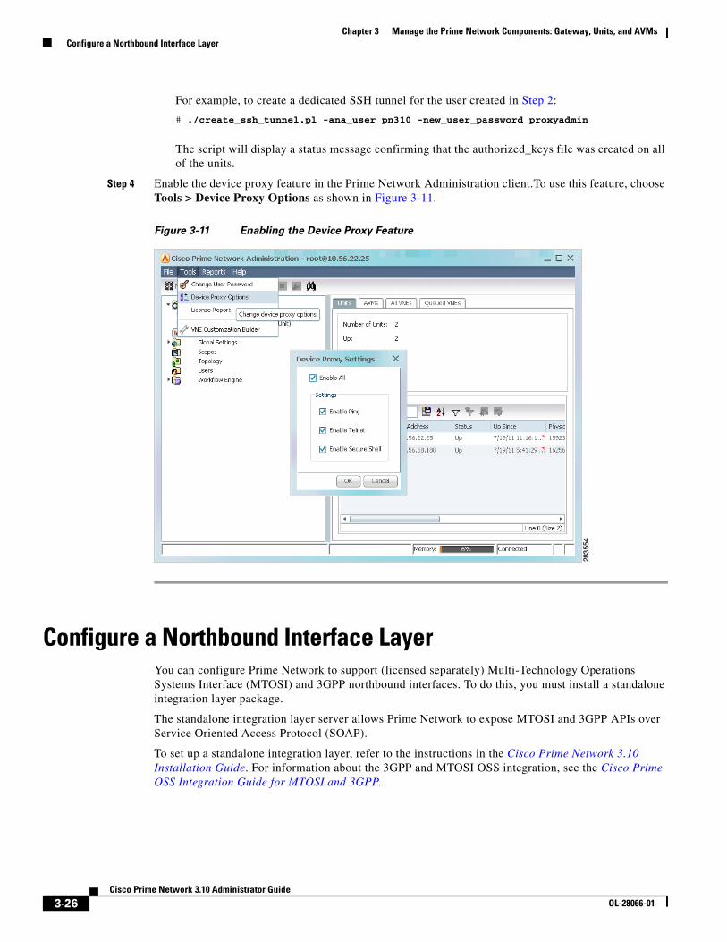
3-26Cisco Prime Network 3.10 Administrator Guide
OL-28066-01
Chapter 3 Manage the Prime Network Components: Gateway, Units, and AVMs Configure a Northbound Interface Layer
For example, to create a dedicated SSH tunnel for the user created in Step 2:
# ./create_ssh_tunnel.pl -ana_user pn310 -new_user_password proxyadmin
The script will display a status message confirming that the authorized_keys file was created on all of the units.
Step 4 Enable the device proxy feature in the Prime Network Administration client.To use this feature, choose Tools > Device Proxy Options as shown in Figure 3-11.
Figure 3-11 Enabling the Device Proxy Feature
Configure a Northbound Interface LayerYou can configure Prime Network to support (licensed separately) Multi-Technology Operations Systems Interface (MTOSI) and 3GPP northbound interfaces. To do this, you must install a standalone integration layer package.
The standalone integration layer server allows Prime Network to expose MTOSI and 3GPP APIs over Service Oriented Access Protocol (SOAP).
To set up a standalone integration layer, refer to the instructions in the Cisco Prime Network 3.10 Installation Guide. For information about the 3GPP and MTOSI OSS integration, see the Cisco Prime OSS Integration Guide for MTOSI and 3GPP.

3-27Cisco Prime Network 3.10 Administrator Guide
OL-28066-01
Chapter 3 Manage the Prime Network Components: Gateway, Units, and AVMs Run a Command on All Units
Run a Command on All UnitsThe script rall.csh runs a given command on all units (not on the gateway), as follows:
# $ANAHOME/rall.csh script
where script is the script name.
The following script example restarts all units:
# $ANAHOME/rall.csh ./Main/networkctl restart
Delete a Prime Network UnitFollow this procedure to delete a unit. You can delete units that have a status of Down, Unreachable, or Disconnected.
Before You Begin
Delete all the VNEs and unreserved AVMs before deleting a unit; see Move and Delete AVMs, page 3-33. The reserved AVMs cannot be deleted.
Use this procedure to remove a unit:
Step 1 In the Prime Network Administration window, select All Servers.
Step 2 Right-click the unit that you want to remove, then choose Delete. A warning message is displayed.
Step 3 Click Yes to proceed or No to cancel the operation. A confirmation message is displayed.
Step 4 Click OK. The unit is deleted and is no longer displayed in the navigation pane and content area.
Create and Configure AVMs and Load BalancingThese topics explain how to create, stop, start, and perform other management operations on AVMs. It also explains how the load balancing feature works, which signals you when an AVM is approaching its memory threshold.
• Add AVMs, page 3-28
• Manage AVM Memory and Thresholds (Load Balancing), page 3-31
• Change AVM Status (Start or Stop), page 3-33
• Move and Delete AVMs, page 3-33
For information on reserved (system) AVMs and how to get information on general AVM properties, see Get AVM Status and Property Information (Including Reserved AVMs), page 3-8.

3-28Cisco Prime Network 3.10 Administrator Guide
OL-28066-01
Chapter 3 Manage the Prime Network Components: Gateway, Units, and AVMs Create and Configure AVMs and Load Balancing
Add AVMsWhen an AVM is created, it is given number (AVM ID) that is unique to the unit and between 101-999. AVMs 0-100 are reserved by Prime Network (see Table 3-2 on page 3-9 for a list of reserved AVMs). Every AVM requires a dedicated TCP port, and the port is created using the following naming convention:
AVM-ID + 2000
For example, if you created AVM 711, it would use port 2711. The appropriate TCP port must be available or the AVM creation will fail, unless you stop the application that is using the port before you create the AVM. (A complete list of ports used by Prime Network is provided in the Cisco Prime Network 3.10 Installation Guide.)
Each AVM has its own log in NETWORKHOME/Main/logs.
If possible, always add AVMs using the auto-add feature. Prime Network will select a unit for the AVM based on memory usage in the system. When you add an AVM (either automatically or manually), the operating system adds an additional 35% to the AVM size. This additional memory is used by the operating system for backend tasks, leaving the desired amount of memory for use by VNEs. Table 3-9 shows how much default memory is assigned to AVMs when they are created.
Auto-Add AVM (Recommended)
Prime Network automated AVM management simplifies the process of creating AVMs and assigning them to units, and monitoring AVM memory load so that it does not adversely impact the system.
When you use the AVM auto-add feature, Prime Network automatically creates new AVMs using the global properties (memory size and threshold) you specify in the Global Settings area of Prime Network Administration. Prime Network will choose the most appropriate unit for you (or you can specify the one you want to use). This is done through the GUI client Auto-Add AVMs option, as shown in Figure 3-12.
Table 3-9 Memory Assigned to AVMs
MethodMemory Assigned to AVM (Default) Total Physical Memory Assigned to AVM
Auto-added AVMs 1500 MB 2025 MB
Manually added AVMs 256 M 345 MB

3-29Cisco Prime Network 3.10 Administrator Guide
OL-28066-01
Chapter 3 Manage the Prime Network Components: Gateway, Units, and AVMs Create and Configure AVMs and Load Balancing
Figure 3-12 AVM Auto-Add
To auto-add AVMS, right-click the desired unit and choose Auto Add AVMs. Prime Network will create eight AVMs to the unit and start the AVMs. Figure 3-13 shows an example of a unit with auto-added AVMs. Prime Network uses the first available 3-digit number (starting at 101) as the AVM ID, and the 3-digit number appended with the parent unit’s IP address as the AVM key.
Figure 3-13 Unit Listing Auto-Added AVMs
You can edit AVM properties by right-clicking the AVM, choosing Properties, and making your changes. The changes will require an AVM restart to take effect.

3-30Cisco Prime Network 3.10 Administrator Guide
OL-28066-01
Chapter 3 Manage the Prime Network Components: Gateway, Units, and AVMs Create and Configure AVMs and Load Balancing
Add AVMs Manually
To manually create an AVM:
Step 1 Expand the All Servers branch and select the unit or gateway that will host the AVM.
Step 2 Open the New AVM dialog box by right-clicking the required unit (or gateway), then choose New AVM. To view an existing AVM, right-click the AVM and select Properties.
Step 3 Enter the following information to create a new AVM. The unit does not have to be up to create the AVM.
Step 4 Click OK. The new AVM is added to the selected unit, is displayed in the content area.
Field Description
ID The name (a number) of the AVM as defined in Prime Network. It must be a unique number on the unit, between 101-999. AVMs 0-100 are reserved and cannot be used.
The AVM will use the TCP port (AVM_nnn + 2000). For example, if you create AVM 711, port number 2711 will be dedicated to that AVM. The appropriate TCP port must be available or the AVM creation will fail, unless you stop the application that is using the port before you create the AVM. (A complete list of ports used by Prime Network is provided in the Cisco Prime Network 3.10 Installation Guide.)
Key A string that uniquely identifies an AVM in the Prime Network system, across all units, thus enabling a transparent failover scenario in the system. The key is displayed as AVMID_nnn, where nnn is an designator assigned by Prime Network for tracking purposes.
Allocated Memory The maximum memory that can be used by the AVM, in megabytes. If you need deployment information and recommendations, such as AVM memory requirements, contact your Cisco account representative.
Note When you create an AVM manually rather than using auto-add, the default AVM size is not determined by the setting specified in Global Settings > Automatic AVM Management. That setting is only applied to auto-added AVMs.
Activate on Creation Loads the AVM into the bootstrap of the unit. This changes the administrative status of the AVM to Up and ensures that the AVM is loaded on subsequent restarts of the unit. By default this option is not checked, and the newly created AVM has an administrative status of Down.
Enable AVM Protection
By default this check box is checked, enabling the watchdog protocol on the AVM. For more information, see Manage Redundancy for Units and Processes, page 5-1.
Note Do not disable this option.

3-31Cisco Prime Network 3.10 Administrator Guide
OL-28066-01
Chapter 3 Manage the Prime Network Components: Gateway, Units, and AVMs Create and Configure AVMs and Load Balancing
Manage AVM Memory and Thresholds (Load Balancing) The AVM load balancing feature continuously monitors the memory used by AVMs that contain at least one VNE. Because VNE memory consumption can change with network configuration changes, it is critical to ensure that AVM memory overflows are quickly addressed. If an AVM is red or has a icon next to it, the AVM has exceeded its memory threshold. When you click the Reduce Load option from the GUI client, Prime Network automatically calculates which VNEs should be moved, and which AVM they should be moved to, in order to reduce the load. This is reported in a dialog box, and you can approve or reject the move.
The load balancing features rely on Prime Network to identify a safe target AVM. A safe target AVM has the following characteristics:
• All of its VNEs are modeled (the discovery process is not running).
• Its available memory is below the AVM Memory Warning Threshold (specified in Global Settings > Automatic AVM Management).
• It is not experiencing any memory consumption problems.
If a safe target AVM is not found, Prime Network waits 2 minutes and tries again.
Note You can also get AVM diagnostic information using the system health and diagnostics tool to check user-defined AVMs health, errors or exceptions, and GC prints. See Prevent System Overloads (Advanced Overload Prevention/Safe Mode), page 8-23.
Whenever a VNE is started, shut down, or removed, Prime Network checks AVM memory. If the total memory used reaches or exceeds the warning threshold, the Prime Network GUI signals the problem by coloring the AVM red, as shown in Figure 3-14.
Figure 3-14 AVM Memory Consumption Indicator in Units Windows
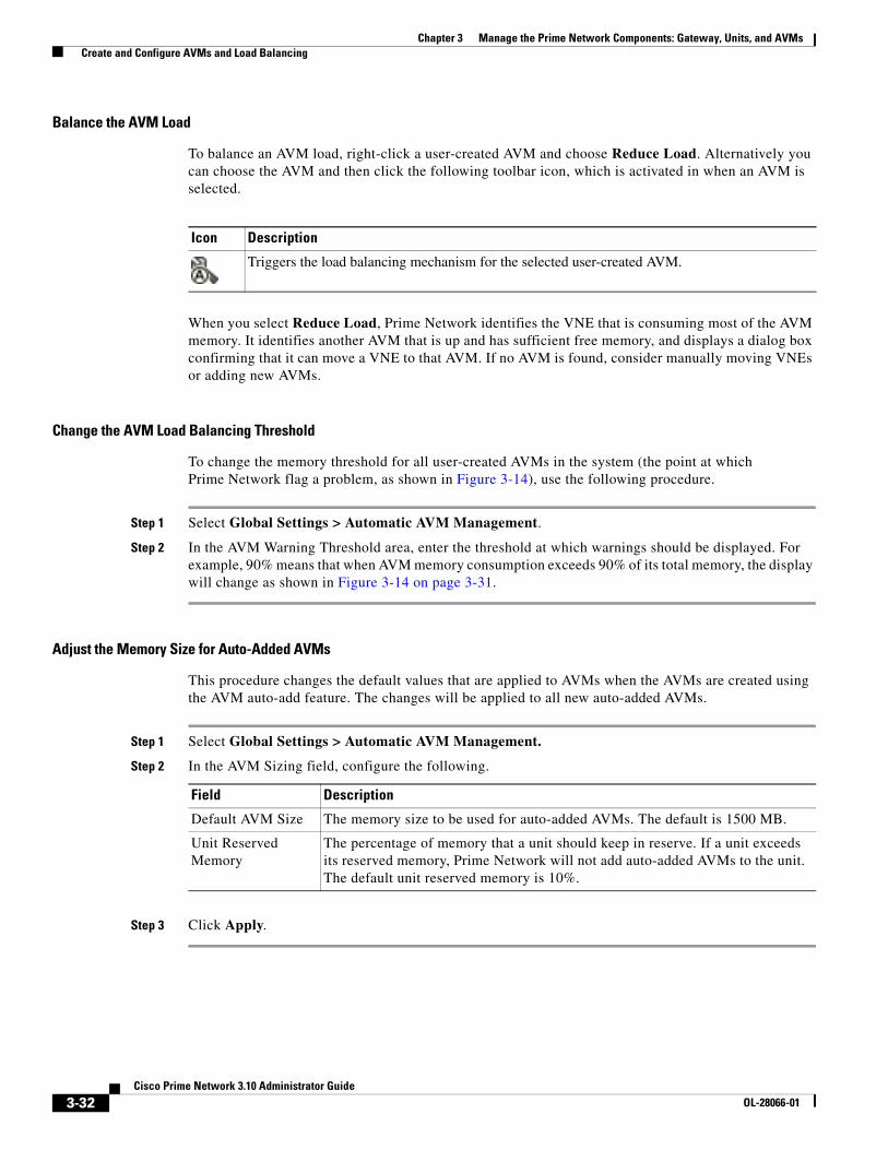
3-32Cisco Prime Network 3.10 Administrator Guide
OL-28066-01
Chapter 3 Manage the Prime Network Components: Gateway, Units, and AVMs Create and Configure AVMs and Load Balancing
Balance the AVM Load
To balance an AVM load, right-click a user-created AVM and choose Reduce Load. Alternatively you can choose the AVM and then click the following toolbar icon, which is activated in when an AVM is selected.
When you select Reduce Load, Prime Network identifies the VNE that is consuming most of the AVM memory. It identifies another AVM that is up and has sufficient free memory, and displays a dialog box confirming that it can move a VNE to that AVM. If no AVM is found, consider manually moving VNEs or adding new AVMs.
Change the AVM Load Balancing Threshold
To change the memory threshold for all user-created AVMs in the system (the point at which Prime Network flag a problem, as shown in Figure 3-14), use the following procedure.
Step 1 Select Global Settings > Automatic AVM Management.
Step 2 In the AVM Warning Threshold area, enter the threshold at which warnings should be displayed. For example, 90% means that when AVM memory consumption exceeds 90% of its total memory, the display will change as shown in Figure 3-14 on page 3-31.
Adjust the Memory Size for Auto-Added AVMs
This procedure changes the default values that are applied to AVMs when the AVMs are created using the AVM auto-add feature. The changes will be applied to all new auto-added AVMs.
Step 1 Select Global Settings > Automatic AVM Management.
Step 2 In the AVM Sizing field, configure the following.
Step 3 Click Apply.
Icon Description
Triggers the load balancing mechanism for the selected user-created AVM.
Field Description
Default AVM Size The memory size to be used for auto-added AVMs. The default is 1500 MB.
Unit Reserved Memory
The percentage of memory that a unit should keep in reserve. If a unit exceeds its reserved memory, Prime Network will not add auto-added AVMs to the unit. The default unit reserved memory is 10%.

3-33Cisco Prime Network 3.10 Administrator Guide
OL-28066-01
Chapter 3 Manage the Prime Network Components: Gateway, Units, and AVMs Create and Configure AVMs and Load Balancing
Change AVM Status (Start or Stop)You can use the Prime Network Administration GUI to start or stop an AVM. When you stop an AVM, all the VNEs in the AVM are stopped. VNEs that were in maintenance mode will move to Down, and the Maintenance indicator in the AVMs window will display false.
If an AVM is red or has a icon next to it, the AVM has exceeded its memory threshold. See Manage AVM Memory and Thresholds (Load Balancing), page 3-31.
Note Any change in status of the AVMs may take some time to be applied. For example, when running the Stop command, it may take several minutes before the status changes from Shutting Down to Down.
To start or stop an AVM:
Step 1 Expand the All Servers branch, then select the required AVM.
Step 2 Right-click the AVM, then choose Actions > Start or Actions > Stop.
The AVM is started or stopped, and the appropriate status is displayed in the content area.
Move and Delete AVMsYou can move user-created AVMs from one unit to another unit. AVMs 0-100 are reserved and cannot be moved.
Note If the unit hosting an AVM is down, disconnect the unit before moving the AVMs. See Stop Unit Communication with the Gateway (Disconnect), page 3-17.
After an AVM is moved, it is reloaded, maintaining the status it was in before the move. The only exception is if a VNE was in maintenance mode. After the move, these VNEs will be in the Down state and the Maintenance indicator (in the AVMs window) will change to false.
Alarm persistency information is saved when you move an AVM to another unit. For more information, see Change Settings That Control VNE Data Saved After Restarts, page 12-36.
When you delete a running AVM, the AVM is stopped and then removed. AVM registry information in the specified unit is deleted. Prime Network will not allow you to stop an AVM if any VNEs are running on the AVM. You cannot delete reserved AVMs (see Table 3-2 on page 3-9 for a list of reserved AVMs).

3-34Cisco Prime Network 3.10 Administrator Guide
OL-28066-01
Chapter 3 Manage the Prime Network Components: Gateway, Units, and AVMs Check the Overall System and Use the Diagnostics (Graphs Tool)
Move an AVM
To move an AVM:
Step 1 In Prime Network Administration, right-click the selected AVM, then choose Move AVM.
Step 2 Browse to and select the unit (branch) where you want to move the AVMs.
Step 3 Click OK. The AVM is moved and now appears beneath the selected unit.
Note Because the system is asynchronous, changes may not appear in the GUI immediately. It may be a few minutes until the GUI client receives a notification from the server and is updated.
For information about moving VNEs, see Move VNEs to Another AVM, page 4-37.
Delete an AVM
Before you delete and AVM, remove all VNEs from the AVM, or the operation will fail. See Delete VNEs, page 4-38.
To delete an AVM:
Step 1 Select the required AVM in the navigation tree. You may select multiple rows.
Step 2 Right-click to display the menu, then choose Delete. A warning message is displayed.
Step 3 Click Yes. A confirmation message is displayed.
Step 4 Click OK. The selected AVM is deleted from the selected unit.
Note Because the system is asynchronous, changes may not appear in the GUI immediately. It may be a few minutes until the GUI client receives a notification from the server and is updated.
Check the Overall System and Use the Diagnostics (Graphs Tool)Whenever a System event of note occurs, it is displayed in the Events GUI client. This includes a variety of events, such as an AVM not responding, events being dropped, a unit switching on due to a failover, and many others. You can also create regular reports that can generate system information you want. For more information, see the Cisco Prime Network 3.10 User Guide.
Prime Network also a web-based diagnostics tool that tracks how the gateway, units, and individual AVMs are operating—Java heap, dropped messages, CPU usage, and so forth. This data is provided in the form of graphs so you can quickly identify problems.
Figure 3-15 shows the default page that is displayed when you first log into the Prime Network Monitoring tool; it is called the MC Loads page.

3-35Cisco Prime Network 3.10 Administrator Guide
OL-28066-01
Chapter 3 Manage the Prime Network Components: Gateway, Units, and AVMs Check the Overall System and Use the Diagnostics (Graphs Tool)
Figure 3-15 MC Loads Page—All Servers (Default)
1 Current date and time on the selected server.
2 Toolbar that controls the sampling period represented in the graphs, and the graph types that are displayed.
3 Web page options:
• MC Loads—Load statistics for the gateway and unit servers. Clicking on an IP address hyperlink launches a drill-down page showing all AVMs.
• Transport—Transport switch counters page showing incoming and outgoing traffic rates, dropped messages, and flood counts.
• Status—Status information about the graphs service—whether the service is up for all units, and when the data was last polled.
4 Hyperlinks for the gateway and units. The gateway is always 127.0.0.1; units are represented by their IP address.
Drill down to a gateway or unit by clicking its hyperlink. This launches a display of information for each AVM on the gateway or unit.
5 Unit and gateway servers rows. Each row represents one unit server. Each color represents an AVM on the unit. The graphs that are organized by column, and the display is controlled by the Remove column drop-down list in the toolbar. (Servers and units run their own graphs processes; units copy the collection results to the gateway server.)
6 Gateway row. Each row represents one gateway server. Each color represents an AVM on the gateway. The graphs are organized by column, and the display is controlled by the Remove column drop-down list in the toolbar.

3-36Cisco Prime Network 3.10 Administrator Guide
OL-28066-01
Chapter 3 Manage the Prime Network Components: Gateway, Units, and AVMs Check the Overall System and Use the Diagnostics (Graphs Tool)
Types of Information You Can Get
The MC Loads page is generally the most useful source of information because it provides a wide variety of diagnostic information:
Transport Counters Page
The Transport Counters page shows the following information
Type of Data Description
Java Heap The sizes of the Java heaps in the AVM processes.
Process Size AVM memory process sizes.
CPU % AVM CPU usage.
GC Time AVM Java Garbage Collector (GC) activity.
Dropped Messages The number of messages dropped in the Prime Network transport messaging mechanism. This can happen when the system is under a heavy load.
Logged Lines The number of lines written to AVM logs.
CPU Total The system CPU metrics for Prime Network unit operation.
Type of Data Description
Traffic The number of traffic frames and traffic bytes sent and received.
Drops The number of dropped frames and dropped bytes, both outgoing and incoming.
Floods The number of flood frames and flood bytes generated and received.
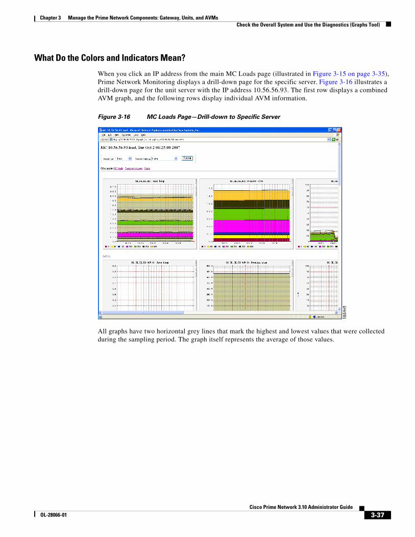
3-37Cisco Prime Network 3.10 Administrator Guide
OL-28066-01
Chapter 3 Manage the Prime Network Components: Gateway, Units, and AVMs Check the Overall System and Use the Diagnostics (Graphs Tool)
What Do the Colors and Indicators Mean?
When you click an IP address from the main MC Loads page (illustrated in Figure 3-15 on page 3-35), Prime Network Monitoring displays a drill-down page for the specific server. Figure 3-16 illustrates a drill-down page for the unit server with the IP address 10.56.56.93. The first row displays a combined AVM graph, and the following rows display individual AVM information.
Figure 3-16 MC Loads Page—Drill-down to Specific Server
All graphs have two horizontal grey lines that mark the highest and lowest values that were collected during the sampling period. The graph itself represents the average of those values.

3-38Cisco Prime Network 3.10 Administrator Guide
OL-28066-01
Chapter 3 Manage the Prime Network Components: Gateway, Units, and AVMs Check the Overall System and Use the Diagnostics (Graphs Tool)
Figure 3-17 Grey Line Indicators in the MC Loads Graphs
Figure 3-18 illustrates some other indicators you may see on MC Loads graphs:
• A color-coded list of AVMs on the server (gateway or unit). These appear in composite graphs, which represent behavior for AVMs on a server. The list is provided below the graph.
• On the Java heap graph, an out-of-memory indicator (a red vertical line) is displayed when an AVM runs out of memory. This is displayed in any graphs that provide Java heap information.
• On all graphs, a restart indicator (a green vertical line) shows when a specific AVM, or the entire server, was restarted.

3-39Cisco Prime Network 3.10 Administrator Guide
OL-28066-01
Chapter 3 Manage the Prime Network Components: Gateway, Units, and AVMs Check the Overall System and Use the Diagnostics (Graphs Tool)
Figure 3-18 Color Indicators in the MC Loads Graphs
Finally, any breaks in the data (blank vertical areas in the graph) mean that data could not be collected for that period.
Use the Tool (Examples)
The web-based tool uses the username admin; the password is configured by the network-conf script during installation. You can change the username and password as described in Change Password for Diagnostics (Graphs) Tool, page 11-12). When you log in for the first time, download and install the security certificate. The tool uses the HTTPS protocol and authentication method.
To access the Prime Network Monitoring tool:
Step 1 Enter https://gateway_ip:1311/graphs in your browser where gateway_ip is the gateway IP address.
A security alert is displayed regarding the site certificate.
Step 2 Click Yes, and enter the username and password.
By default, the tool displays load statistics collected during the past hour for the gateway and unit servers (the MC Loads graphs; see Figure 3-15 on page 3-35). You can select a sampling period by choosing from the Period drop-down list and clicking Submit.
The following are some examples of how you can use the MC Loads page:
• Check the Java heap on AVM 11 on the gateway server as in indicator of gateway memory usage.
• Drill down to specific user-defined AVMs (that are hosting VNEs) to examine their health, look for errors or exceptions, and watch GC prints.

3-40Cisco Prime Network 3.10 Administrator Guide
OL-28066-01
Chapter 3 Manage the Prime Network Components: Gateway, Units, and AVMs Check the Overall System and Use the Diagnostics (Graphs Tool)
• Check the Dropped Messages graph of each unit and gateway, paying special attention to AVM 25 (the Event Persistence AVM, which would indicate drops related to event handling).
• Ensure that the GC is not taking more than 20-30 seconds (except at system startup).
The following topics provide examples of some of these uses and how to interpret the graphs on the MC Loads page.
AVM Memory Consumption
For memory consumption, we recommend that 30% of the AVM memory remain free (in a steady state). The Java heap graph provides a visual way to check this rate. The following example shows that approximately 15% of the memory is available.
Stable memory consumption, or a constant sawteeth-shaped graph, reflects a healthy AVM. The sawtooth graph indicates the normal behavior of the Java GC, which releases unused objects on a regular basis. This behavior is expected but should not be followed by an overall growth in the memory consumption.
Few unique cases to consider when looking at Prime Network heap graphs:
• Very high and wide sawtooth—The AVM has extra memory available for allocation; GC runs in a low priority thread and is triggered as less memory is available. A suggested response is to add more VNEs to the AVM in a gradual manner, monitoring the AVM memory usage during the process.
• Very sharp sawtooth over a short period of time—The system is attempting to deallocate memory and is triggering GC very frequently. This may result from an AVM being too overloaded with VNEs, or specific VNEs being very large and busy. Depending on your use case, suggested responses are to allocate more memory to the AVM, reduce the number of VNEs in the AVM, or reduce the VNE polling cycles.
A gradual increase in the graph indicates that the AVM is using increasingly more memory. If there was no change to the AVM content, or to the network managed by the VNEs in the AVM, this may indicate a memory leak. In the following example, there is a memory leak in AVM 11.

3-41Cisco Prime Network 3.10 Administrator Guide
OL-28066-01
Chapter 3 Manage the Prime Network Components: Gateway, Units, and AVMs Check the Overall System and Use the Diagnostics (Graphs Tool)
High CPU Example
In this example, the system is configured with an embedded database and the Oracle process is causing high CPU usage.
Note In this example the Oracle process is experiencing a high CPU event. However, at system startup, it is also normal for AVMs to consume 100% of the CPU for a short period of time.

3-42Cisco Prime Network 3.10 Administrator Guide
OL-28066-01
Chapter 3 Manage the Prime Network Components: Gateway, Units, and AVMs Check the Overall System and Use the Diagnostics (Graphs Tool)
Fatal AVM Error (AVM Restart) Example
This example shows a fatal AVM error that caused an AVM restart. Common causes of this problem are out-of-memory errors and core dumps.
Change Sampling Periods and Refresh Settings
The following table shows the different sampling rates for the data that is collected, based on their age. Data is discarded after 28 days.
You can change the graph display by entering additional parameters in the browser URL field, in an HTTP GET format. Table 3-10 describes the parameters you can use, along with examples.
Age of Data How Data is Saved
Up to 3 hours old Data is saved every 15 seconds.
3-24 hours old Data is diluted to a sampling rate of 300 seconds.
24 hours to 7 days old Data is diluted to a sampling rate of 15 minutes.
7-28 days old Data is diluted to a sampling rate of 2 hours.
More than 28 days old Data is discarded.
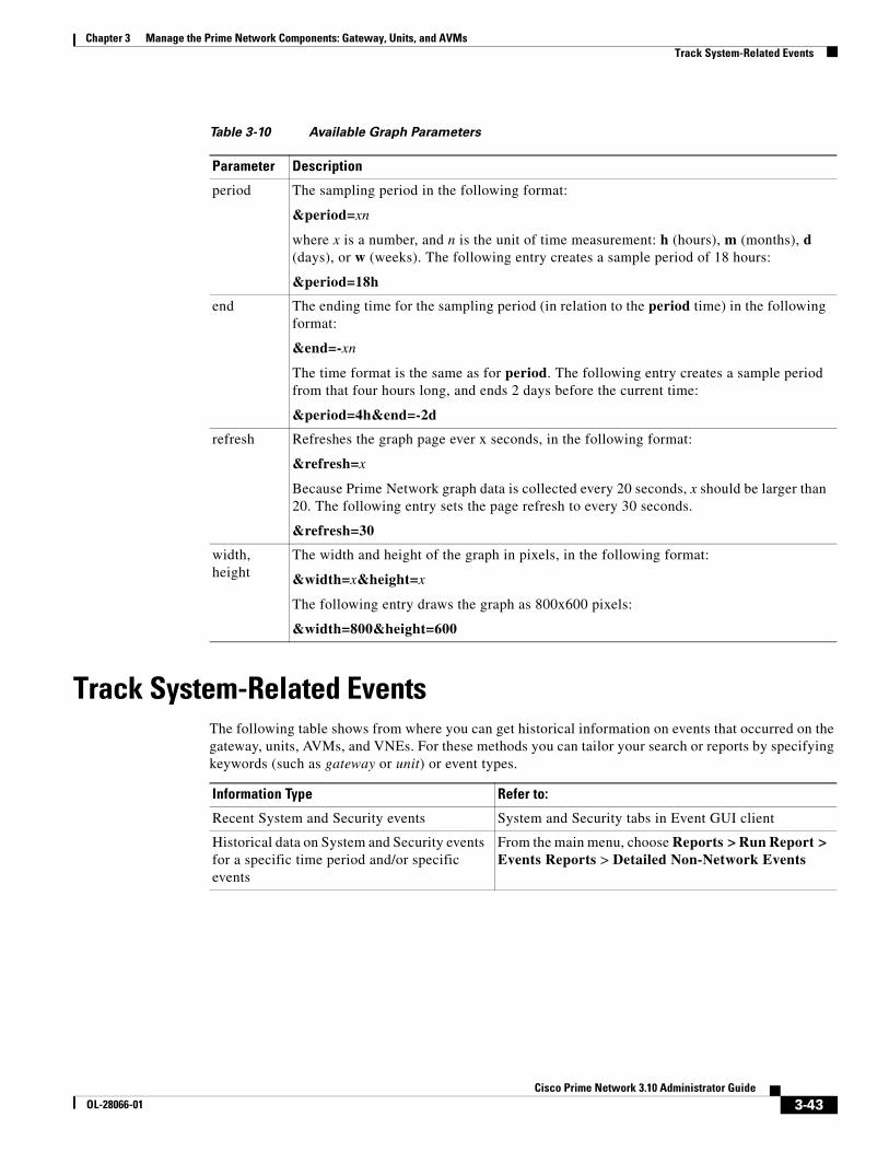
3-43Cisco Prime Network 3.10 Administrator Guide
OL-28066-01
Chapter 3 Manage the Prime Network Components: Gateway, Units, and AVMs Track System-Related Events
Track System-Related EventsThe following table shows from where you can get historical information on events that occurred on the gateway, units, AVMs, and VNEs. For these methods you can tailor your search or reports by specifying keywords (such as gateway or unit) or event types.
Table 3-10 Available Graph Parameters
Parameter Description
period The sampling period in the following format:
&period=xn
where x is a number, and n is the unit of time measurement: h (hours), m (months), d (days), or w (weeks). The following entry creates a sample period of 18 hours:
&period=18h
end The ending time for the sampling period (in relation to the period time) in the following format:
&end=-xn
The time format is the same as for period. The following entry creates a sample period from that four hours long, and ends 2 days before the current time:
&period=4h&end=-2d
refresh Refreshes the graph page ever x seconds, in the following format:
&refresh=x
Because Prime Network graph data is collected every 20 seconds, x should be larger than 20. The following entry sets the page refresh to every 30 seconds.
&refresh=30
width,height
The width and height of the graph in pixels, in the following format:
&width=x&height=x
The following entry draws the graph as 800x600 pixels:
&width=800&height=600
Information Type Refer to:
Recent System and Security events System and Security tabs in Event GUI client
Historical data on System and Security events for a specific time period and/or specific events
From the main menu, choose Reports > Run Report > Events Reports > Detailed Non-Network Events

3-44Cisco Prime Network 3.10 Administrator Guide
OL-28066-01
Chapter 3 Manage the Prime Network Components: Gateway, Units, and AVMs Track System-Related Events

C H A P T E R
4-1Cisco Prime Network 3.10 Administrator Guide
OL-28066-01
4Configure VNEs and Troubleshoot VNE Problems
VNEs are the building blocks of Prime Network model. These topics focus on VNEs—how devices are discovered by VNEs, how to check and troubleshoot VNE problems, and how to make changes to VNEs. Add Devices to Prime Network, page 4-10, explains the various methods you can use to create VNEs and thus add devices to the model, including how to decide which method is best for your configuration.
• What is the Difference Between a VNE and a Device?, page 4-1
• Check Device Discovery, VNE Status, and VNE States, page 4-2
• Stop, Start, and Move VNEs to Maintenance Mode, page 4-9
• Add Devices to Prime Network, page 4-10
• Add New Device Support by Installing Device Packages, page 4-26
• Change a VNE IP Address and Other VNE Properties, page 4-33
• Move VNEs to Another AVM, page 4-37
• Delete VNEs, page 4-38
• Track VNE-Related Events, page 4-62
See these topics for step-by-step procedures for troubleshooting modeling and connectivity problems:
• Troubleshoot Device Connectivity Issues (VNE Communication States), page 4-39
• Troubleshoot Device Modeling Issues (VNE Investigation States), page 4-52
What is the Difference Between a VNE and a Device?Actions you perform on VNEs are different from actions you perform on devices. It is important to understand the difference between VNEs and devices. VNEs are autonomous, miniature engines, and each VNE is in charge of a single device. The VNE maintains a real-time virtual model of the device (both physical and logical), and its connectivity references to its immediate neighbors. The VNE is an entity that only exists within Prime Network; the real device is a separate entity. For example:
• A VNE has properties such as a VNE scheme, a VNE driver, and a VNE location. The scheme and driver determine the information that is modeled and monitored by Prime Network, and the location identifies where the autonomous engine is running and how it is connected to the gateway. These items are listed on the VNE Properties dialog which you can launch by right-clicking a VNE and choosing Properties. These properties are managed using the Administration GUI client.
• A device has properties such as a device series and model number, an NE software version, a chassis with slots, and a routing entities table. Device information and actions are managed using the Vision and Events GUI clients (they are normally unaware of VNEs and other backend processes). You can

4-2Cisco Prime Network 3.10 Administrator Guide
OL-28066-01
Chapter 4 Configure VNEs and Troubleshoot VNE Problems Check Device Discovery, VNE Status, and VNE States
also see a subset of NE properties from the Administration GUI client by right-clicking an NE and choosing Inventory. (To see the complete physical and logical inventory and device events, you must use the Vision or Events GUI clients.)
Operators are shielded from much of the backend workings of the VNE because their concern is the real NE being managed. But the VNE process must be completely functional in order for Prime Network to properly model and monitor the device. This administrative condition of the VNE is expressed through the VNE status.
Check Device Discovery, VNE Status, and VNE StatesThe Prime Network GUI clients provide some common information so that you do not have to switch between clients. For example, just as you can get a subset of VNE information from the Vision GUI client, you can also get a subset of device information from the Administration GUI client. The following table shows what type of information is displayed in the Administration GUI client when you right-click a VNE and choose either Properties or Inventory.
These topics explain how Prime Network discovers devices and how to check on the status of modeling and connectivity.
• How VNEs are Modeled and Monitored, page 4-3
• Check VNE General Status (Up, Down, Disconnected, Unreachable), page 4-5
• Check VNE Communication State (Connectivity), page 4-6
• Check VNE Investigation States (Modeling), page 4-7
From VNE Menu Displays:
Properties VNE-related properties:
• Name, scheme, type, status, VNE driver version
• Protocol settings: SNMP, Telent/SSH, XML, HTTP, ICMP, TL1, and so forth
• Adaptive polling settings (for high CPU events)
• Events settings (if the VNE is listening to additional IP addresses)
VNE Properties Reference, page D-1
Inventory Device-related properties:
• Device vendor, product, device series, serial number, and so forth.
• Software system and version
• “Up since” data, contact, location
Cisco Prime Network 3.10 User Guide
Clicking VNE Status displays communication details:
• Protocol version and connectivity status
• Whether the device is using event-based (reduced) polling
• Whether the device is generating syslogs or traps
Clicking VNE Details opens the VNE Properties window (listed in the first row of this table).
Check VNE Communication State (Connectivity), page 4-6

4-3Cisco Prime Network 3.10 Administrator Guide
OL-28066-01
Chapter 4 Configure VNEs and Troubleshoot VNE Problems Check Device Discovery, VNE Status, and VNE States
How VNEs are Modeled and MonitoredWhen you add a device to Prime Network, Prime Network creates an autonomous VNE that models that single device. The VNE then uses the NE’s IP address and southbound management interfaces (such as SNMP or Telnet) to identify the NE by vendor, device family, device subfamily, device type and software version. When the NE type is determined, the VNE collects the basic inventory, both physical and logical, determines its status, and attempts to determine its place in the network topology. The VNE negotiates with peer VNEs (which represent peer NEs) to determine the connectivity and topology at different layers. This model of the network topology, device state, and device inventory is constantly being updated by the VNE, which tracks every change that occurs in the NE or in the network.
VNE Schemes
The information that the VNE collects is determined by the VNE scheme. You choose a scheme when you create a VNE. VNE schemes determine what data should be retrieved for each device, and which commands and protocols Prime Network should use to collect that data. When you create a VNE, Prime Network provides a drop-down of available schemes:
For example, devices poll with SNMP, but might also use CLI to poll additional information. Because the IpCore scheme assumes that the device is used as part of an MPLS VPN network containing P and PE devices, Prime Network therefore models these VNEs in a slightly different way. In most cases you can use the Product scheme with customer edge (CE) devices. You can designate a VNE as a core router by setting it to work with the IpCore scheme, or as an edge router by setting it to work with the Product scheme.
If you only want to model a certain set of technologies, create a custom scheme. The scheme is added to the gateway, and you can apply it to VNEs using the Administration client. See Create a Custom VNE Scheme, page 4-11.
For guidance on choosing a scheme, see Choosing a VNE Scheme (Check Technologies and Device Types), page A-2.
How VNEs Are Monitored and Updated
A VNE’s administrative condition is conveyed by its VNE status—for example, if you stop a VNE, its VNE status will be Down. VNE states, on the other hand, describe the degree to which the VNE has discovered and modeled a device, and the disposition of the communication between the VNE and the device it models. VNE state information is intentionally granular so that you can use it to troubleshoot problems.
Scheme Use this scheme:
Product For devices that are not part of the network core, such as the Cisco 800 Series or 2900 Series.
IpCore For devices that are part of the network core, such as the Cisco 3600 Series, 12000 GSR (Gigabit Switch Router) Series, or CRS (Carrier Routing System) Series.
EMS For devices where only system information and physical inventory should be polled (that is, the minimum amount of data). It is supported on all devices but does not support any technologies.
Default For cases where you are not sure which scheme to choose. Prime Network will use the Product scheme.

4-4Cisco Prime Network 3.10 Administrator Guide
OL-28066-01
Chapter 4 Configure VNEs and Troubleshoot VNE Problems Check Device Discovery, VNE Status, and VNE States
All VNEs have two states:
Both the communication and investigation states are displayed in Prime Network Vision when you open a device properties window, as shown in Figure 4-1.
Figure 4-1 VNE Communication and Investigation States (in Prime Network Vision)
VNE State DescriptionFor more information:
Communication state
Describes the status of communication between devices and VNEs, and VNEs and the gateway server. If a communication state changes, Prime Network generates a Service event.
Check VNE Communication State (Connectivity), page 4-6
Investigation state
Describes the degree to which the VNE has successfully discovered and modeled a network element. In other words, it gives you an idea of the quality and stability of the device inventory.
Because investigation states frequently change, Prime Network does not generate a Service event whenever a VNE’s investigation state changes (although you can configure it to do so).
Check VNE Investigation States (Modeling), page 4-7

4-5Cisco Prime Network 3.10 Administrator Guide
OL-28066-01
Chapter 4 Configure VNEs and Troubleshoot VNE Problems Check Device Discovery, VNE Status, and VNE States
Note If a VNE was stopped, you will see a message and a refresh button at the top of the properties window. When the VNE is restarted, refresh the window to repopulate the information. If you receive an error message, it means the VNE is still down. To start the VNE, see Stop, Start, and Move VNEs to Maintenance Mode, page 4-9.
If you want more information about the communication state, click Communication Details to get information on the status of:
• Protocols the device uses to communicate with the VNE.
• Traps and syslog forwarding from the device to the VNE.
This information is helpful for troubleshooting device reachability problems. For more information, see Check VNE Communication State (Connectivity), page 4-6.
Check VNE General Status (Up, Down, Disconnected, Unreachable)Like AVM status, VNE status indicates the administrative condition of the VNE: Starting Up, Up, Shutting Down, Down. If the gateway server cannot communicate with the VNE, the VNE status will be Unreachable. (Remember that this is the status of the VNE, not the status of the physical device.) This information is displayed in the Administration GUI client when you select an AVM (see Figure 4-2).
Figure 4-2 VNE Status in AVM Window
Starting and stopping VNEs is entirely user-directed, as explained in Stop, Start, and Move VNEs to Maintenance Mode, page 4-9. Table 4-1 lists the possible VNE status values that you may see in a table of VNEs.
Table 4-1 VNE Status
VNE Status Description
Starting Up A Start (command) option was issued.
Up The VNE process is reachable, was loaded, and has started. This is the status when a Start command is issued (or when you create a VNE and choose Start as its initial status), and no problems are encountered (such as an overloaded server).
Shutting Down A Stop (command) option was issued and, while the command is being run, some processes are still running, the status of the VNE is Shutting Down.

4-6Cisco Prime Network 3.10 Administrator Guide
OL-28066-01
Chapter 4 Configure VNEs and Troubleshoot VNE Problems Check Device Discovery, VNE Status, and VNE States
Check VNE Communication State (Connectivity)VNE communication states convey the status of connectivity between:
• The VNE and the device it models (management communication)
• The VNE and the gateway (agent communication)
When connectivity problems occur, it is normally in the management area—that is, between a VNE and a device. Devices and VNEs communicate using SNMP, Telnet, ICMP, traps, syslogs, and others—all of which determine whether a device is truly reachable. If a problem occurs, Prime Network runs tests tailored to each (enabled) protocol to determine the seriousness of the problem. Prime Network does not change the communication state to Device Unreachable unless all of the enabled device management protocols are unresponsive, and the device is not generating syslogs or traps.
Table 4-2 describes all of the possible VNE communication states. It also shows the GUI decorator for each state, where applicable. For information on troubleshooting communication state issues, see Steps to Troubleshoot VNE Communication State Issues, page 4-41.
The icon indicates a network element has been deleted (or moved). The state will show N/A for Cloud VNEs because Cloud VNEs do not represent a real network element (see Create Connections for Unmanaged Network Segments (Cloud VNEs and Links), page 12-42).
Down The VNE process is reachable, but was stopped. This is the status when a Stop command is issued. The VNE is both operationally and administratively down.
VNEs that were in maintenance mode will move to the Down state in the following circumstances:
• The VNE was moved.
• The AVM was restarted or moved.
• The unit was disconnected or was switched to a standby server.
• The gateway was restarted.
Unreachable The VNE cannot be reached by the gateway, so the VNE cannot be managed.
Note This is the VNE status, not the device status; the device may be fully reachable.
Disconnected The VNE is on a unit that was disconnected from the gateway (the unit has a Disconnected status).
Table 4-1 VNE Status (continued)
VNE Status Description
Table 4-2 VNE Communication States
State Name Description Badge
Agent Not Loaded
The VNE is not responding to the gateway because it was stopped, or it was just created. This communication state is the equivalent of the Defined Not Started investigation state.
None
VNE/Agent Unreachable
The VNE is not responding to the gateway. This can happen if the unit or AVM is overutilized, the connection between the gateway and unit or AVM was lost, or the VNE is not responding in a timely fashion. (A VNE in this state does not mean the device is down; it might still be processing network traffic.)

4-7Cisco Prime Network 3.10 Administrator Guide
OL-28066-01
Chapter 4 Configure VNEs and Troubleshoot VNE Problems Check Device Discovery, VNE Status, and VNE States
Check VNE Investigation States (Modeling)VNE investigation states describe how successfully a VNE has modeled the device it represents. These states describe all of the possibilities in the VNE life cycle, from when the VNE is added to Prime Network, through the device modelling, until the VNE is stopped. Table 4-3 describes all of the possible VNE investigation states. It also shows the GUI decorator for each state, where applicable.
Note At any time you can restart the VNE discovery process by restarting the VNE (see Stop, Start, and Move VNEs to Maintenance Mode, page 4-9). If you want to rediscover only a certain element within a device, go to the Prime Network Vision GUI client, open the device inventory, and right-click the element and choose Poll Now.
For troubleshooting information, see Troubleshoot Device Modeling Issues (VNE Investigation States), page 4-52.
The icon indicates a network element has been deleted (or moved). The state will show N/A for Cloud VNEs because Cloud VNEs do not represent a real network element (see Create Connections for Unmanaged Network Segments (Cloud VNEs and Links), page 12-42).
Connecting The VNE is starting and the initial connection has not yet been made to the device. This is a momentary state. Because the investigation state decorator (the hourglass) will already be displayed, a special GUI decorator is not required.
None
Device Partially Reachable
The element is not fully reachable because at least one protocol is not operational.
Note This is the default behavior. You can change the settings that determine when Cisco Prime Network moves a VNE to Device Unreachable. For more information, see VNE Management Communication Policies and How To Change Them, page 12-24.
Device Reachable
All element protocols are enabled and connected.
Note This is the default behavior. You can change the settings that determine when Cisco Prime Network moves a VNE to Device Unreachable. For more information, see VNE Management Communication Policies and How To Change Them, page 12-24.
None
Device Unreachable
The connection between the VNE and the device id down because all of the protocols are down (though the device might be sending traps or syslogs).
Note This is the default behavior. You can change the settings that determine when Cisco Prime Network moves a VNE to Device Unreachable. For more information, see VNE Management Communication Policies and How To Change Them, page 12-24.
Tracking Disabled
The reachability detection process is not enabled for any of the protocols used by the VNE (specifically, the trackreachability registry key is not set to true; see Change How Protocols are Tested for Reachability, page 12-29). The VNE will not perform reachability tests nor will Cisco Prime Network generate reachability-related events. In some cases this is desirable; for example, tracking for Cloud VNEs should be disabled because Cloud VNEs represent unmanaged network segments.
Because this is a user-defined mode (rather than an error or transitional mode), Cisco Prime Network does not display a decorator for this state. To troubleshoot a VNE that is in this state, check the VNE Status Details window; see Troubleshoot Device Connectivity Issues (VNE Communication States), page 4-39.
None
Table 4-2 VNE Communication States (continued)
State Name Description Badge

4-8Cisco Prime Network 3.10 Administrator Guide
OL-28066-01
Chapter 4 Configure VNEs and Troubleshoot VNE Problems Check Device Discovery, VNE Status, and VNE States
Table 4-3 VNE Investigation States
State Name Description Badge
Defined Not Started
A new VNE was created (and is starting); or an existing VNE was stopped. In this state, the VNE is managed and is validating support for the device type. (This investigation state is the equivalent of the Agent Not Loaded communication state.) A VNE remains in this state until it is started (or restarted).
None
Unsupported The device type is either not supported by Prime Network or is misconfigured (it is using the wrong scheme, or is using reduced polling but the device does not support it).
To extend Cisco Prime Network functionality so that it recognizes unsupported devices, use the VNE Customization Builder. See the Cisco Prime Network 3.10 Customization Guide.
Discovering The VNE is building the model of the device (the device type was found and is supported by Cisco Prime Network). A VNE remains in this state until all device commands are successfully executed at least once, or until there is a discovery timeout.
Operational The VNE has a stable model of the device. Modeling may not be fully complete, but there is enough information to monitor the device and make its data available to other applications, such as activation scripts. A VNE remains in this state unless it is stopped or moved to the maintenance state, or there are device errors.
None
Currently Unsynchronized
The VNE model is inconsistent with the device. This can be due to a variety of reasons; for a list of these reasons along with troubleshooting tips, see Troubleshoot Device Connectivity Issues (VNE Communication States), page 4-39.
Maintenance VNE polling was suspended because it was manually moved to this state (by right-clicking the VNE and choosing Actions > Maintenance). The VNE remains in this state until it is manually restarted. A VNE in the maintenance state has the following characteristics:
• It does not poll the device or process traps and syslogs.
• It maintains the status of any existing links.
• It responds to VNE reachability requests.
• It passively participates in correlation flow issues (but is not an initiator).
The VNE is moved to the Stopped state if: it is VNE is moved, the parent AVM is moved or restarted, the parent unit switches to a standby unit, or the gateway is restarted.
Partially Discovered
The VNE model is inconsistent with the device because a required device command failed, even after repeated retries. A common cause of this state is that the device contains an unsupported module. To extend Cisco Prime Network functionality so that it recognizes unsupported modules, use the VNE Customization Builder. See the Cisco Prime Network 3.10 Customization Guide.
Shutting Down The VNE has been stopped or deleted by the user, and the VNE is terminating its connection to the device.
Stopped The VNE process has terminated; it will immediately move to Defined Not Started. None
http://www.cisco.com/en/US/products/ps11879/products_installation_and_configuration_guides_list.html

4-9Cisco Prime Network 3.10 Administrator Guide
OL-28066-01
Chapter 4 Configure VNEs and Troubleshoot VNE Problems Stop, Start, and Move VNEs to Maintenance Mode
Stop, Start, and Move VNEs to Maintenance ModeYou can start or stop a VNE, or move a VNE to maintenance mode using the Administration GUI client. When you change the status of a VNE, some information is persisted. Persisted information is data that is stored for later use. (For information on the VNE persistency mechanism, see Persistency Overview, page 12-36.)
Restarting a VNE reinitiates the discovery process. If you want to rediscover only a certain element within a device, go to the Prime Network Vision GUI client, open the device inventory, and right-click the element and choose Poll Now.
To change a VNE’s status, select the VNE and choose one of the following from the right-click Actions menu.
• Start—Starts the VNE process and triggers its discovery process. The VNE will move through a status of Starting Up to Up. When the VNE is Up, its process is running and it is reachable.
• Stop—Stops the VNE process. The VNE will move through a status of Shutting Down to Down. In the GUI, the Maintenance indicator in the AVMs window will display false. (If you stop a VNE that was in maintenance mode, its Maintenance indicator will change to false. This is also true if the VNE is moved, if its parent AVM is moved or stopped, if the gateway is restarted, or if it is on a unit that is switched to a standby unit.)
• Maintenance—Stops some VNE functionality so that you can perform maintenance operations without affecting the overall functionality of the active network. This is useful during planned outages such as software upgrades, hardware modifications, or cold reboots. For more details about what a VNE in the maintenance state does or does not do, see Table 4-3 on page 4-8.
If you change the device software—for example, you install a newer version of Cisco Cat OS—you do not need to restart the VNE. The VNE will gather the new information at its next scheduled poll. However, if you change VNE software, you must restart the VNE for your changes to take effect; see Add New Device Support by Installing Device Packages, page 4-26.
The following table shows the badge used to indicate that a VNE is in maintenance mode.
To change the state of a VNE or move it to maintenance mode:
Step 1 Expand the All Servers branch, and select the required AVM in the navigation tree.
Step 2 Select the required VNE in the VNEs Properties table.
Step 3 Perform one of the following actions:
• To start the VNE, right-click Actions > Start, or click Start in the toolbar. A confirmation message is displayed. Click OK. An Up status is eventually displayed in the VNEs Properties table. You might see a Starting Up status if the gateway is overloaded or if the VNE is still being loaded. If the AVM hosting the VNE is in a Down status, the VNE status remains Starting Up until the VNE is brought up.
• To stop the VNE, right-click Actions > Stop, or click Stop in the toolbar. A confirmation message is displayed. Click OK. A Down status is eventually displayed in the VNEs Properties table. You might see a Shutting Down status while processes are shutting down.
Badge Description
Indicates that a VNE is in maintenance mode in Prime Network Vision (and when pressed in a toolbar, moves a VNE to maintenance mode). In Prime Network Administration, the AVMs window will show the VNE Maintenance indicator as true.

4-10Cisco Prime Network 3.10 Administrator Guide
OL-28066-01
Chapter 4 Configure VNEs and Troubleshoot VNE Problems Add Devices to Prime Network
• To place the VNE in maintenance mode, right-click Actions > Maintenance, or click Maintenance in the toolbar. A confirmation message is displayed. Click OK. A Maintenance status is displayed in the VNEs Properties table.
Add Devices to Prime NetworkThese topics provide the information you need to create VNEs so that Prime Network can model and manage the devices in your network.
• Steps and Required Information for Adding VNEs, page 4-10
• Create Custom VNE Schemes and VNE Defaults for SNMP and Telnet/SSH, page 4-11
• Methods for Adding Devices (Creating VNEs), page 4-12
• Clone an Existing Device, page 4-14
• Add a New Device Type, page 4-17
• Add Devices Using Network Discovery, page 4-19
• Add Devices Using a CSV File, page 4-22
Steps and Required Information for Adding VNEsAlways perform these steps before adding VNEs, regardless of which method you use. These prerequisites have a direct effect on how successfully Prime Network will model and monitor the device.
Table 4-4 Basic Steps for Adding VNEs
Step Task Description, or where to get more information
Step 1 Choose a VNE scheme, or create a new one (this controls the data that is retrieved, and which protocols are used)
Choosing a VNE Scheme (Check Technologies and Device Types), page A-2
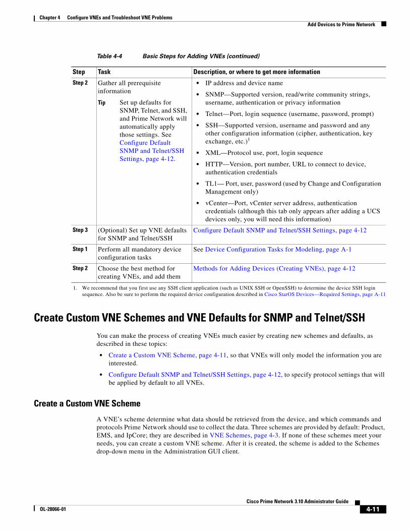
4-11Cisco Prime Network 3.10 Administrator Guide
OL-28066-01
Chapter 4 Configure VNEs and Troubleshoot VNE Problems Add Devices to Prime Network
Create Custom VNE Schemes and VNE Defaults for SNMP and Telnet/SSHYou can make the process of creating VNEs much easier by creating new schemes and defaults, as described in these topics:
• Create a Custom VNE Scheme, page 4-11, so that VNEs will only model the information you are interested.
• Configure Default SNMP and Telnet/SSH Settings, page 4-12, to specify protocol settings that will be applied by default to all VNEs.
Create a Custom VNE Scheme
A VNE’s scheme determine what data should be retrieved from the device, and which commands and protocols Prime Network should use to collect the data. Three schemes are provided by default: Product, EMS, and IpCore; they are described in VNE Schemes, page 4-3. If none of these schemes meet your needs, you can create a custom VNE scheme. After it is created, the scheme is added to the Schemes drop-down menu in the Administration GUI client.
Step 2 Gather all prerequisite information
Tip Set up defaults for SNMP, Telnet, and SSH, and Prime Network will automatically apply those settings. See Configure Default SNMP and Telnet/SSH Settings, page 4-12.
• IP address and device name
• SNMP—Supported version, read/write community strings, username, authentication or privacy information
• Telnet—Port, login sequence (username, password, prompt)
• SSH—Supported version, username and password and any other configuration information (cipher, authentication, key exchange, etc.)1
• XML—Protocol use, port, login sequence
• HTTP—Version, port number, URL to connect to device, authentication credentials
• TL1— Port, user, password (used by Change and Configuration Management only)
• vCenter—Port, vCenter server address, authentication credentials (although this tab only appears after adding a UCS devices only, you will need this information)
Step 3 (Optional) Set up VNE defaults for SNMP and Telnet/SSH
Configure Default SNMP and Telnet/SSH Settings, page 4-12
Step 1 Perform all mandatory device configuration tasks
See Device Configuration Tasks for Modeling, page A-1
Step 2 Choose the best method for creating VNEs, and add them
Methods for Adding Devices (Creating VNEs), page 4-12
1. We recommend that you first use any SSH client application (such as UNIX SSH or OpenSSH) to determine the device SSH login sequence. Also be sure to perform the required device configuration described in Cisco StarOS Devices—Required Settings, page A-11
Table 4-4 Basic Steps for Adding VNEs (continued)
Step Task Description, or where to get more information

4-12Cisco Prime Network 3.10 Administrator Guide
OL-28066-01
Chapter 4 Configure VNEs and Troubleshoot VNE Problems Add Devices to Prime Network
A best practice is to create a new scheme for one VNE and test it before applying the new scheme to other VNEs. This is suggested because Prime Network does not perform an validation on your chosen technologies.
You cannot delete schemes that are currently being used by any VNEs. If you edit a scheme that is being used by a VNE, the changes are only applied to the VNE if the VNE is restarted.
Step 1 Choose Global Settings > Scheme Management. All of the existing schemes are listed. You can edit all schemes except for Product, EMS, and IpCore.
Step 2 Right-click Scheme Management and choose New Customized Scheme. Prime Network displays a dialog box that lists all technologies.
Step 3 Enter a name and description, and then choose the technologies you want to model or not model by selecting them and clicking Enable or Disable. The category column can help you decide whether you should include a technology, based on the network type.
Step 4 Verify your changes, and click OK.
The new scheme is added to the list of supported schemes and is listed on the Schemes drop-down list in the VNE properties dialog.
Configure Default SNMP and Telnet/SSH Settings
When you create default settings for the SNMP and Telnet/SSH protocols, the settings are automatically applied to all new VNEs
Note Be sure the protocols are enabled in the VNE properties dialog box.
To configure default VNE settings, choose Global Settings > Default VNE Settings.
• Default Telnet SSH Setting are described in VNE Properties: Telnet/SSH, page D-6.
• Default SNMP Settings are described in VNE Properties: SNMP, page D-5.
To find out what version of SNMP or SSH a VNE is using, right-click the VNE and choose Inventory and click VNE Status.
Methods for Adding Devices (Creating VNEs)Prime Network provides a variety of ways to add VNEs. The recommended best practice is the VNE auto-add feature. The auto-add mechanism calculates the predicted memory consumption based on a VNE’s role and type. Using that information, Prime Network assigns VNEs to units and AVMs, and balances AVM memory as the VNEs are added. You can monitor the VNEs as Prime Network adds them to the system.
Tip Start your operations from the All Servers branch (that is, right-click All Servers and choose the operation). Prime Network will use the auto-add feature.

4-13Cisco Prime Network 3.10 Administrator Guide
OL-28066-01
Chapter 4 Configure VNEs and Troubleshoot VNE Problems Add Devices to Prime Network
Table 4-5 briefly describes the methods for creating VNEs and the scenarios for which they are suitable. In all of these cases, you can let Prime Network choose the best unit and AVM, or you can specify them yourself.
Note If Prime Network is installed with Cisco Prime Central, be sure to use a device’s SYSNAME as its VNE name. This allows the device to be recognized across the common inventory. Also, do not use None or All as the SYSNAME, because those names have internal meaning to Cisco Prime Central.
How VNE Auto-Add Works
When you use the VNE auto-add feature—that is, you create VNEs from the All Servers branch—Prime Network will choose the appropriate unit and AVM for the VNE. If you want the VNEs to be hosted by a specific unit, you can perform the operation from the unit (in the navigation tree), and Prime Network will only choose the appropriate AVM.
Prime Network locates the best AVM by identifying safe target AVMs. A safe target AVM has the following characteristics:
• All of its VNEs are modeled (the discovery process is not running).
• Its available memory is below the AVM Memory Warning Threshold (specified in Global Settings > Automatic AVM Management).
• It is not experiencing any memory consumption problems.
Auto-added VNEs are listed in the Queued VNEs tab (under All Servers) as the VNEs are assigned to AVMs. They are removed once they are assigned to an AVM and unit.
If Prime Network cannot locate an appropriate AVM, it waits 2 minutes and tries again. It will continue retrying until an AVM is found. Note that even when you use the auto-add feature, before the VNEs are created, you can choose a unit or AVM for a drop-down list in the VNE properties dialog.
Table 4-5 Methods for Adding VNEs to Prime Network
If this is your situation: Use this method: For instructions, see:
The devices you want to add are similar to devices are already managed by Prime Network
Clone an existing VNE and use auto-add
Clone an Existing Device, page 4-14
The devices you want to add are not similar to devices are already managed by Prime Network
Create a VNE “from scratch” and use auto-add
Add a New Device Type, page 4-17
You are testing a new VNE driver on an existing device
You are adding many devices and they already exist in your network, and none of the IP addresses are duplicated
Use Network Discovery (uses auto-add)
Add Devices Using Network Discovery, page 4-19
You are adding many devices and you want to adjust individual properties using a spreadsheet
Create a CSV file of properties and then use it to create VNEs (uses auto-add, but you can disable it)
Add Devices Using a CSV File, page 4-22

4-14Cisco Prime Network 3.10 Administrator Guide
OL-28066-01
Chapter 4 Configure VNEs and Troubleshoot VNE Problems Add Devices to Prime Network
Figure 4-3 illustrates how Prime Network identifies the best AVM and unit in the auto-add process.
Figure 4-3 VNE Auto-Add
Clone an Existing DeviceA clone VNE inherits all of the properties of an existing VNE (including the Device Package being used by the existing VNE). You only have to specify a different name and IP address. Prime Network will choose the best unit and AVM for the VNE, but you can override this with your own choice. Once you have created the clone VNEs, you can still edit their properties before creating them.
Before You Begin
Make sure you have performed any required tasks that are described in Steps and Required Information for Adding VNEs, page 4-10. This will ensure that the VNE is properly modeled and updated.
Step 1 Choose the appropriate launch point, depending on whether you want to use the auto-add feature:
Isa preferred
unitspecified?
Doessystem containa unit with safetarget AVMs?
VNE is moved from QueuedVNEs to specified AVM.
Yes
Yes
No
No
User addsVNE using
auto-assignment
Doesthe preferredunit containsafe targetAVMs–*?
System waits2 minutesand retries
System waits2 minutesand retries
2833
15
Yes
No
To create VNEs where: Start the clone operation from this point in the GUI client:
Prime Network chooses the unit and AVM
From All Servers in the navigation area, click All VNEs tab.
Prime Network chooses the AVM but you choose the unit
From desired unit in the navigation area, click Unit’s VNEs tab.
You choose the unit and AVM From desired unit in the navigation area, click the desired AVM
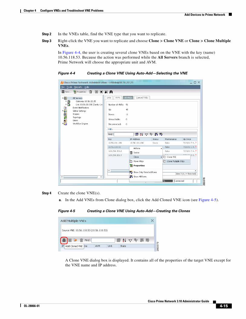
4-15Cisco Prime Network 3.10 Administrator Guide
OL-28066-01
Chapter 4 Configure VNEs and Troubleshoot VNE Problems Add Devices to Prime Network
Step 2 In the VNEs table, find the VNE type that you want to replicate.
Step 3 Right-click the VNE you want to replicate and choose Clone > Clone VNE or Clone > Clone Multiple VNEs.
In Figure 4-4, the user is creating several clone VNEs based on the VNE with the key (name) 10.56.118.53. Because the action was performed while the All Servers branch is selected, Prime Network will choose the appropriate unit and AVM.
Figure 4-4 Creating a Clone VNE Using Auto-Add—Selecting the VNE
Step 4 Create the clone VNE(s).
a. In the Add VNEs from Clone dialog box, click the Add Cloned VNE icon (see Figure 4-5).
Figure 4-5 Creating a Clone VNE Using Auto-Add—Creating the Clones
A Clone VNE dialog box is displayed. It contains all of the properties of the target VNE except for the VNE name and IP address.

4-16Cisco Prime Network 3.10 Administrator Guide
OL-28066-01
Chapter 4 Configure VNEs and Troubleshoot VNE Problems Add Devices to Prime Network
b. Enter the new VNE name and IP address. When finished, click OK.
Note If Prime Network is installed with Cisco Prime Central, be sure to use a device’s SYSNAME as its VNE name. This allows the device to be recognized across the common inventory. Also, do not use None or All as the SYSNAME, because those names have internal meaning to Cisco Prime Central.
c. Repeat this step to create additional clones of the VNE. As you create more clones, they are added to the dialog box.
Step 5 To edit the VNE properties before creating the VNEs (for example, to specify a unit or AVM, use a different scheme, and so forth), right-click the VNE and select Edit VNE (see Figure 4-6). If you want, you can specify the unit and AVM you want the VNE to use.
Figure 4-6 Creating a Clone VNE Using Auto-Add—Viewing and Editing the Clones
Step 6 Click Finish. To check the status of the VNEs:
a. For auto-added VNEs (the unit or AVM was selected by Prime Network), select All Servers branch and click the Queued VNEs tab. If it is empty, the VNEs have been assigned.
b. To find the VNE’s assignment, click the All VNEs tab and check the unit column.
c. Go to the unit and click the Unit’s VNEs tab to check the AVM.

4-17Cisco Prime Network 3.10 Administrator Guide
OL-28066-01
Chapter 4 Configure VNEs and Troubleshoot VNE Problems Add Devices to Prime Network
Figure 4-7 shows two new VNEs that were added to the gateway but are using AVM auto-assignment. Their assignment is pending.
Figure 4-7 Creating a Clone VNE Using Auto-Add—Checking the Assignment
Add a New Device TypeIf you are creating a VNE for a new device type, you should create a single VNE instance “from scratch” and test it to ensure its settings are correct. You can then clone it as described in Clone an Existing Device, page 4-14.
Before You Begin
Make sure you have performed any required tasks in Steps and Required Information for Adding VNEs, page 4-10. This will ensure that the VNE is properly modeled and updated.
Step 1 Choose the appropriate launch point, depending on how much control you want over the unit and AVM:
To create the VNE(s) where: Start from this point in the GUI client:
Prime Network chooses the unit and AVM All Servers > New VNE
Prime Network chooses the AVM but you choose the unit Unit > New VNE
You choose the unit and AVM Unit > AVM > New VNE

4-18Cisco Prime Network 3.10 Administrator Guide
OL-28066-01
Chapter 4 Configure VNEs and Troubleshoot VNE Problems Add Devices to Prime Network
Step 2 The New VNE dialog box is displayed, opened to the General tab. The following table lists the tabs in the VNE properties window and where you can get more information on the fields in those tabs. Most VNEs only require a VNE name and IP address.
VNE Tab Description Described in:
General Enter general information such as VNE name, IP address, and scheme. By default, Prime Network uses the newest DP installed on the gateway or unit. If you are creating a single VNE, you can specify a different DP from the drop-down list.
Note If Prime Network is installed with Cisco Prime Central, be sure to use a device’s SYSNAME as its VNE name. This allows the device to be recognized across the common inventory.
VNE Properties: General, page D-2
SNMP Specifies SNMP information and credentials to support polling and device reachability. The fields displayed in the dialog box depend on the protocol you select.
VNE Properties: SNMP, page D-5
Telnet/SSH Enables Telnet and SSH for device reachability and investigation, including the Telnet sequence and SSH prompts. The fields displayed in the dialog box depend on the protocol you select.
VNE Properties: Telnet/SSH, page D-6
XML Enables XML for device reachability and investigation. VNE Properties: XML, page D-12
HTTP Enables HTTP or HTTPS for device reachability and investigation.
VNE Properties: HTTP, page D-13
TL1 Enables the TL1 management protocol for running scripts on the device (used by Change and Configuration Management only).
VNE Properties: TL1, page D-14
ICMP Enables ICMP and the ICMP polling rate (in seconds) for device reachability testing.
VNE Properties: ICMP, page D-13
Polling Associates a VNE with a previously created polling group or allows you to configure different polling settings according to the type of VNE information you want (status, configuration, and so forth).
VNE Properties: Polling, page D-14
Adaptive Polling
Controls how the VNE should respond to high CPU events. VNE Properties: Adaptive Polling, page D-16
Events Specifies other IP addresses on which the VNE should listen for syslogs and traps.
VNE Properties: Events, page D-17
vCenter Enables connections to a Cisco UCS vCenter server using the HTTP or HTTPS communication protocol for vCenter reachability and investigation. (
Note This tab is displayed after the VNE is created.
VNE Properties: vCenter, page D-18

4-19Cisco Prime Network 3.10 Administrator Guide
OL-28066-01
Chapter 4 Configure VNEs and Troubleshoot VNE Problems Add Devices to Prime Network
Step 3 Click Finish. Check the status of the VNEs in the VNEs table. For auto-added VNEs:
a. Select All Servers branch and click the Queued VNEs tab. If it is empty, the VNEs have been assigned.
b. To find the VNE’s assignment, click the All VNEs tab and check the unit column.
c. Go to the unit and click the Unit’s VNEs tab to check the AVM.
Add Devices Using Network Discovery
Note Use the Network Discovery feature from a Mozilla Firefox, Google Chrome, or Apple Safari browser. Otherwise it may not be displayed properly. Supported browsers are listed in the Cisco Prime Network 3.10 Installation Guide.
The Network Discovery feature will automatically discover your network devices by traversing the network. Use this method if you are not very familiar with the types of devices in your network. The only required information is an IP address for a seed device, and the SNMPv 2 or SNMPv 3 credentials. This information is added to a discovery profile that specifies the IP and SNMP information, along with any additional protocols or filters you want Prime Network to use. You can use multiple discovery techniques in your filter in order to locate and discover the largest number of devices.
Once your profile is complete, run the discovery job. Prime Network will use its auto-add feature to assign VNEs to AVMs. When the job is finished, a result report provides a listing of devices that were successfully located, devices that were filtered out, and devices that reported credential errors. Prime Network will not create any VNEs until it receives confirmation to proceed. After the discovery job completes, you can instruct Prime Network to create VNEs for the devices that were successfully located. For the devices with credential errors, you can correct or create a new profile, or create the VNEs manually.
Note Network discovery is supported on the following device operating systems: Cisco IOS, Cisco IOS XR, Cisco IOS XE, Cisco Nexus OS, Cisco Cat OS, Juniper and operating system. The Network Discovery feature is not supported in networks that have duplicate IP addresses.
Before You Begin
Make sure of the following:
• You have performed any necessary tasks that are described in Steps and Required Information for Adding VNEs, page 4-10. This will ensure that the VNE is properly modeled and updated.
• The gateway running the discovery process must be able to reach the target devices using the management protocols (SNMP and Telnet/SSH).
Step 1 Choose Tools > Network Discovery.
Step 2 Click New to create a new discovery profile. The profile determines how Prime Network can locate, identify, and communicate with devices in order to discover them. To add profile information:
• Click the plus sign next to the technique you want to add.
• Check the enable check box for the technique.

4-20Cisco Prime Network 3.10 Administrator Guide
OL-28066-01
Chapter 4 Configure VNEs and Troubleshoot VNE Problems Add Devices to Prime Network
• Click Add Row and enter your data.
• Click Save to save the discovery techniques.
Provide a unique name, and configure the discovery profile.
Profile Information Description
Discovery Technique
Methods Prime Network should use to discover devices. You can specify multiple techniques in order to locate and discover the largest number of devices
Ping Sweep Instructs Prime Network to ping a range of IP addresses, and add any devices that respond to the ping. You must specify a seed device IP address and subnet mask to specify a range of IP addresses.
Note Ping Sweep is the most commonly-used method.
Protocol Data Techniques
Instructs Prime Networkm to use other protocols to discover devices, and when a device is found, how many hops further to discover. You must specify a seed device IP address and the allowed number of hops from the device.
Note If both BGP and OSPF are specified in the same discovery profile, the seed devices specified for each protocol will be combined. For example, if you specify 192.0.2.1 as a seed device for BGP and 192.0.2.2 as a seed device for OSPF, both 192.0.2.1 and 192.0.2.2 will be used for BGP and OSPF. To avoid this, you can create separate discovery profiles – one using BGP and one using OSPF for discovery.
Credential Settings
Pool of credentials Prime Network should use to communicate with and discover the devices. You can use SNMPv2, SNMPv3, Telnet, and SSH.
Note SNMPv2 or SNMPv3 credentials are required.
Management IP Selection Method
Method the system should use to identify which device IP address should be used as the management IP address:
Discovered IP This is default method. Use discovered IP as management IP address.
Loopback If the IP address is a loopback, Ethernet, Token Ring, or Serial interface, use its highest IP address as the management IP address.
System Name Perform a DNS lookup of the system name to verify the validity of the IP address, and:
• If it is verified, use that IP address as the management IP address.
• If it is not verified, use the original IP address used to discover the device as the management IP address.
DNS Reverse Lookup
Perform a reverse DNS lookup of the system name to verify the validity of the IP address, and:
• If it is verified, use that IP address as the management IP address.
• If it is not verified, use the original IP address used to discover the device as the management IP address.

4-21Cisco Prime Network 3.10 Administrator Guide
OL-28066-01
Chapter 4 Configure VNEs and Troubleshoot VNE Problems Add Devices to Prime Network
d. Click Save to save your profile. It is automatically added to the Discovery Profiles table.
Step 3 Start the network discovery by selecting the discovery profile and clicking Run.
Step 4 Choose Network Discovery > Discovery Results and choose your job. The table provides the following information; click the Refresh button at the top right of the window to update the information.
Filters (Optional) Criteria for including or excluding devices from the list of discovered devices.
System Location
Filter by physical/geographic location of the device as specified in the SYSTEM-MIB). If your network devices are configured with the system location, you can use this filter option.
Optional Filters
• IP—Filter by IP address.
• System Object ID—Filter by device type as specified in the SYSTEM-MIB.
• DNS Filter—Filter by domain name (after the system resolves the name of the device from the DNS server).
Profile Information Description
Column Description
Name Discovery job name (profile name plus system-assigned number)
Status Status of discovery job
Job is running or is completed with no credential errors
Job is running or completed and encountered credential errors. Consider running the job again or creating the VNE manually.
Job was aborted
Start Time,End Time
Start and end time of discovery job
Discovery Profile
Name of profile being used by job
Reachable Number of discovered devices that are reachable and manageable using the specified credentials (before creating the VNEs, you can change the VNE scheme and reduced polling setting; Step 5)
Filtered Number of devices that were filtered out (for a list of these devices, click the Filtered tab at the bottom of the Discovery Results window)
Credential Error
Number of devices that were identified but could not be managed because of credential problems (for a list of these devices, click the Credential Errors tab at the bottom of the Discovery Results window)

4-22Cisco Prime Network 3.10 Administrator Guide
OL-28066-01
Chapter 4 Configure VNEs and Troubleshoot VNE Problems Add Devices to Prime Network
Step 5 To create VNEs for the reachable devices, use this procedure. Prime Network will auto-add the VNEs—that is, it will choose the unit and AVM for each VNE.
a. Click the Reachable tab at the bottom of the Discovery Results window.
b. If you want to change the VNE scheme or reduced polling setting before creating the VNEs, click the Edit button and change the settings. For information on schemes and reduced polling, see Choosing a VNE Scheme (Check Technologies and Device Types), page A-2, and Reduced Polling, page 12-3.
c. Select the devices you want Prime Network to manage, and click Create VNEs. The Status column will change as the VNE goes through the creation process.
Add Devices Using a CSV FileUsing a CSV file to add VNEs is helpful when you have a large number of VNEs to create and you want to organize your information using a spreadsheet template. After you create the spreadsheet, copy it to the gateway server, and then provide it as input to the Add Multiple VNEs dialog box. Prime Network will auto-add the VNEs—that is, it will choose the unit and AVMs for the VNEs. The new VNEs will use the latest installed DP (the newest DP that is installed on the gateway or unit). If there are any errors, Prime Network will clearly display them. If any fields are left blank, Prime Network uses the defaults specified in Table 4-6.
Format of a CSV File
The CSV file supports all of the entry names listed in Table 4-6. A general guideline is that you should supply the following entries in your file, at a minimum:
elementName,ip,SNMPEnabled,SnmpVersionEnum,adminStatusEnum ,SchemeName,avm,unitIP,ICMPPollingRate,ICMPEnabled,PollingGroup,TrapSyslogSources,TelnetSequence,telnetEnabled
The following is the text of a sample CSV file. This CSV file is also provided on the gateway server at NETWORKHOME/Main/scripts/BulkVNEImportExample.csv.
elementName,ip,SNMPEnabled,SnmpVersionEnum,adminStatusEnum ,SchemeName,avm,unitIP,ICMPPollingRate,ICMPEnabled,PollingGroup,TrapSyslogSources,TelnetSequence,telnetEnabledm1,1.1.1.1,TRUE,1,0,ipcore ,,,50000000,TRUE,slow,,">,prompt,#,",TRUEm2,1.1.1.2,TRUE,2,1,product,,,856000,FALSE,default,,#,TRUEm3,1.1.1.3 ,TRUE,2,1,,,,,TRUE,,"129.5.6.2,55.23.6.5,9.5.2.1",">,text,#,",FALSEm4,1.1.1.4,TRUE,1,0,,,,,FALSE,,121.2.3.4,,TRUEm5,1.1.1.5,TRUE ,1,0, ipcore ,,,5600000,FALSE ,slow,121.2.3.4,">,admin,#,",FALSE
Status Description
Found Device has been located.
In Progress VNE creation process is starting.
Queued VNE was created but has not yet been assigned to an AVM (in the Administration GUI client, they will show a status of Queued).
Naming Conflict A VNE with that name or IP address already exists. (Correct it and try again.)
IP Conflict
Assigned VNE was created and assigned to an AVM. You can check the AVM assignment by located the VNE is the Administration GUI client.

4-23Cisco Prime Network 3.10 Administrator Guide
OL-28066-01
Chapter 4 Configure VNEs and Troubleshoot VNE Problems Add Devices to Prime Network
Table 4-6 Supported Values for CSV File (Creating VNEs)
CSV Entry Supported Values Default Setting and Notes
General Properties
elementName
Note If Prime Network is installed with Cisco Prime Central, be sure to use a device’s SYSNAME as its VNE name. This allows the device to be recognized across the common inventory. Also, do not use None or All as the SYSNAME, because those names have internal meaning to Cisco Prime Central.
string or IP address Mandatory field1
ip vne IP address Mandatory field
elementClassEnum 0=AutoDetect, 1=Generic SNMP, 2=Cloud, 3=ICMP
0 (AutoDetect)
SchemeName default (= product), product, ipcore, ems, existing custom schemes
product
adminStatusEnum 0=Disabled (do not start VNE), 1=Enabled (start VNE)
1 (start VNE)2
avm avm ID (null) (Use auto-add)
unitIP unit IP address (null) (Use auto-add)
SNMP Properties
SNMPEnabled TRUE=Enabled, FALSE=Disabled
TRUE
SnmpVersionEnum 0=SNMPv1, 1=SNMPv2, 2=SNMPv3
1 (SNMPv1)
SNMPReadCommunity string public
SNMPWriteCommunity string private
SnmpV3AuthenticationEnum 0=noauth, 1=auth_no_priv, 2=priv
0 (noauth)
SnmpV3AuthenticationUserProfile string (null)
SnmpV3AuthenticationPassword string (null)
SnmpV3AuthenticationProtocolEnum 0=md5, 1=sha (null)
SnmpV3EncryptionPassword string (null)
SnmpV3EncryptionTypeEnum 0=des, 1=aes128, 2=aes192, 3=aes256
(null)

4-24Cisco Prime Network 3.10 Administrator Guide
OL-28066-01
Chapter 4 Configure VNEs and Troubleshoot VNE Problems Add Devices to Prime Network
Telnet/SSH Properties
TelnetEnabled TRUE=Enabled, FALSE=Disabled
FALSE
TelnetProtocolEnum 0=Telnet, 1=SSHv1, 2=SSHv2
0 (Telnet)
TelnetPortNumber port-number 23 (Telnet), 22 (SSHv1/v2)
TelnetSequence “sequence” (null)
SshCipherEnum 0=DES, 1=3DES, 2=Blowfish 1 (3DES)
SshAuthenticationEnum 0=password 0 (password)
SshV1Username string (null)
SshV1Password string (null)
SshV2Username string (null)
SshV2Password string (null)
XML Properties
XMLPortNumber port-number 38751 (Telnet), 52 (SSL)
XmlProtocolEnum 0=Telnet, 1=SSL 0 (Telnet)
XMLEnabled TRUE=Enabled, FALSE=Disabled
FALSE
XMLSequence string (null)
HTTP Properties3
HTTPPortNumber port-number 80
HttpProtocolEnum 0=HTTP, 1=HTTPS 0 (HTTP)
HTTPEnabled TRUE=Enabled, FALSE=Disabled
FALSE
HTTPManagementPath string (null)
HTTPAuthenticationRequired TRUE=Required, FALSE=Not required
FALSE
HTTPUserName string (null)
HTTPPassword string (null)
TL1Enabled TRUE=Enabled, FALSE=Disabled
FALSE
TL1PortNumber port-number (null)
TL1Username string (null)
TL1Password string (null)
ClientAuthEnum 0=password, 1=public 0 (password)
ClientPrivateKey string (null)
ServerAuthEnum 0=none, 1=save-first-auth, 2=preconfigured
2 (preconfigured)
Table 4-6 Supported Values for CSV File (Creating VNEs) (continued)
CSV Entry Supported Values Default Setting and Notes

4-25Cisco Prime Network 3.10 Administrator Guide
OL-28066-01
Chapter 4 Configure VNEs and Troubleshoot VNE Problems Add Devices to Prime Network
Before You Begin
Make sure you have performed any necessary tasks that are described in Steps and Required Information for Adding VNEs, page 4-10. This will ensure that the VNE is properly modeled and updated.
Step 1 Select All Servers > Add Multiple VNEs > Using Default Values.
Step 2 In the Add Multiple VNEs dialog box:
a. Click the Import VNEs from File icon as shown in Figure 4-8.
ServerPublicKey string (null)
FingerPrint string (null)
ServerAuthDataTypeEnum 0=fingerprint, 1=public-key 0 (fingerprint)
KeyExchange string (null)
MAC 0=sha1, 1=md5, 2=sha1-96, 3=md5-96
(null)
Cipher 0-3DES, 1=AES-128, 2=AES-192, 3=AES-256
(null)
HostKeyAlgo 0-DSA, 1=RSA (null)
IsActionNotAllowed TRUE=Not allowed, FALSE=Allowed
(null)
ICMP Properties
ICMPEnabled TRUE=Enabled, FALSE=Disabled
FALSE
ICMPPollingRate number (milliseconds) (null)
Polling Properties
PollingGroup slow, default default
AdaptivePollingSettingEnum 0=Prime Network Settings, 1=Device Type Settings, 2=Local Settings
1 (Device Type Settings)
Events Properties
TrapSyslogSources “IP address[,IP address,...]” (null)
1. For existing VNEs, you cannot overwrite the VNE name or IP address using a CSV file. To change a VNE name or IP address you must delete the existing VNE and create a new one.
2. If you use auto-add, the VNE will automatically be started regardless of this setting.
3. These settings are not used by VNEs provided with the initial release of Prime Network 3.10. Future Device Packages will introduce new device support for devices that will use this feature.
Table 4-6 Supported Values for CSV File (Creating VNEs) (continued)
CSV Entry Supported Values Default Setting and Notes

4-26Cisco Prime Network 3.10 Administrator Guide
OL-28066-01
Chapter 4 Configure VNEs and Troubleshoot VNE Problems Add New Device Support by Installing Device Packages
Figure 4-8 Creating VNEs from a CSV File—Selecting the CSV File
b. Navigate to the file location, select the file, and click Open. The Add Multiple VNEs dialog box is populated with the data from the CSV file.
Red text indicates a conflict with an existing VNE. Fix the problem by proceeding to the next step.
Step 3 To edit any VNE properties before creating the VNEs (for example, to specify a unit or AVM, use a different scheme, and so forth), right-click the VNE and select Edit VNE (see Figure 4-6).
Note You can still add individual VNEs using the Clone VNE icon shown in Figure 4-5 on page 4-15.
Step 4 To check the status of the VNEs:
a. For auto-added VNEs (the unit or AVM was selected by Prime Network), select All Servers branch and click the Queued VNEs tab. If it is empty, the VNEs have been assigned.
b. To find the VNE’s assignment, click the All VNEs tab and check the unit column.
c. Go to the unit and click the Unit’s VNEs tab to check the AVM.
Add New Device Support by Installing Device PackagesThese topics explain how to extend Prime Network NE support using the Device Package mechanism, including how to use the ivne script to install and manage DPs:
• Find Out if New Device Support is Available, page 4-27
• Identify Which DPs Are Installed on the Gateway, page 4-28
• Identify Which Driver a VNE Is Using, page 4-29
• Change the Device Package a VNE Is Using, page 4-30
• Download and Install New Driver Files, page 4-30
• Uninstall a Device Package, page 4-32
Note When you upgrade a device’s operating system (such as installing a Cisco Catalyst OS update), you do not need to restart the VNE. When the VNE polls for configuration information, it will detect the changes and will restart itself. When the VNE reloads, it will update any required registry information, such as the VNE registry path.
Device Packages are downloadable packages that contain a group of VNE driver jar files. When you add a device to Prime Network, Prime Network identifies the NE by vendor, device family, device subfamily, device type and software version. This is done by matching the device with its appropriate VNE driver

4-27Cisco Prime Network 3.10 Administrator Guide
OL-28066-01
Chapter 4 Configure VNEs and Troubleshoot VNE Problems Add New Device Support by Installing Device Packages
jar file. The driver jar file contains information about software versions, physical and logical entities, syslogs, traps, and activation scripts, all of which enable Prime Network to properly model and monitor the device.
Between releases of Prime Network, updates to driver jar files are packaged together and delivered in Device Packages (DPs). As new DPs become available, the DP and its Readme file are placed on the Prime Network Software Download site on Cisco.com, and the new support is documented in the Addendum: Additional VNE Driver Support for Cisco Prime Network 3.10. Once you download a Device Package, you can install it using the ivne script. Once a DP is installed, if you right-click a VNE and choose Update VNE Device Package, the new DP is listed along will available DPs.
Understanding Version Numbers in VNE Driver Jar Files and DPs
VNE driver jar files are cumulative and contain all the enhancements that are provided in earlier versions. All jar files use the following versioning practice:
Vendor-JarType-VNEJarVersion.jar
JarType can be Modules, Commons, or device-specific. For example:
Similarly, DPs contain the latest version of all available jars. Even if a jar is not revised for a DP, it is still included in to ensure that all available enhancements are installed. After installing a DP using the ivne script, no changes are applied to a VNE until you restart it.
Prime Network 3.10 DPs use the following versioning practice:
PrimeNetwork-3.10-DPyymm
For example, PrimeNetwork-3.10-DP1212 is the December 2012 DP for Prime Network 3.10.
Find Out if New Device Support is AvailableWhen a new DP is released, the new support is documented in Addendum: Additional VNE Driver Support for Cisco Prime Network 3.10. The addendum is a companion guide to the Cisco Prime Network 3.10 Supported Cisco VNEs and other supported documents on Cisco.com, which lists the support provided with the base release.
There are DP-specific documents that describe the DP contents and how to install the DP. They are provided with the DP on the Prime Network Software Download site (thus they are available when the the first DP is released):
• A Readme file that describes the DP, including the new support, resolved and open bugs, and links to previous Readmes.
• Cisco Prime Network 3.10 VNE Device Package Installation Guide (available when the first DP is released)
Jar File Example Description
Cisco-Commons-v1.0.0.0.jar First release of jar file with support common to all Cisco devices.
Cisco-Modules-v1.0.0.0.jar First release of jar file with support common to all Cisco modules.
Cisco-ASR90xx-v2.0.0.0.jar Second release of jar file with support common to all ASR 9000 Series Aggregation Services Routers. Contains all of the support provided in version 1.0.0.0.
Cisco-3750ME-v1.0.0.0.jar First release of jar file with support common to all Cisco Catalyst 3750 Metro Series Switches.
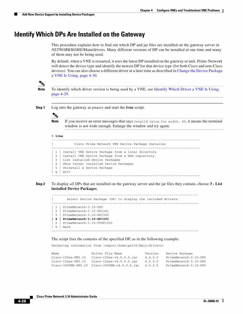
4-28Cisco Prime Network 3.10 Administrator Guide
OL-28066-01
Chapter 4 Configure VNEs and Troubleshoot VNE Problems Add New Device Support by Installing Device Packages
Identify Which DPs Are Installed on the GatewayThis procedure explains how to find out which DP and jar files are installed on the gateway server in NETWORKHOME/Main/drivers. Many different versions of DP can be installed at one time and many of them may not be being used.
By default, when a VNE is restarted, it uses the latest DP installed on the gateway or unit. Prime Network will detect the device type and identify the newest DP for that device type (for both Cisco and non-Cisco devices). You can also choose a different driver at a later time as described in Change the Device Package a VNE Is Using, page 4-30.
Note To identify which driver version is being used by a VNE, see Identify Which Driver a VNE Is Using, page 4-29.
Step 1 Log into the gateway as pnuser and start the ivne script.
Note If you receive an error messages that says Invalid value for width: 80, it means the terminal window is not wide enough. Enlarge the window and try again.
# ivne------------------------------------------------------------------------------| Cisco Prime Network VNE Device Package Installer ------------------------------------------------------------------------------| 1 | Install VNE Device Package from a local directory | 2 | Install VNE Device Package from a Web repository | 3 | List installed Device Packages | 4 | Show latest installed Device Packages | 5 | Uninstall a Device Package | q | Quit ------------------------------------------------------------------------------
Step 2 To display all DPs that are installed on the gateway server and the jar files they contain, choose 3 - List installed Device Packages.
-----------------------------------------------------------------------------| Select Device Package (DP) to display the included drivers. -----------------------------------------------------------------------------| 1 | PrimeNetwork-3.10-DP0 | 2 | PrimeNetwork-3.10-DP1301 | 3 | PrimeNetwork-3.10-DP1302 | 4 | PrimeNetwork-3.10-DP1303 | 5 | PrimeNetwork-3.10-TPDP1303 | 6 | Back -----------------------------------------------------------------------------
The script lists the contents of the specified DP, as in the following example:
Gathering information from /export/home/pn310/Main/drivers/
Name Driver File Name Version Device PackageCisco-100xx-PN3.10 Cisco-100xx-v4.0.0.0.jar 4.0.0.0 PrimeNetwork-3.10-DP0Cisco-12xxx-PN3.10 Cisco-12xxx-v4.0.0.0.jar 4.0.0.0 PrimeNetwork-3.10-DP0Cisco-3400ME-PN3.10 Cisco-3400ME-v4.0.0.0.jar 4.0.0.0 PrimeNetwork-3.10-DP0

4-29Cisco Prime Network 3.10 Administrator Guide
OL-28066-01
Chapter 4 Configure VNEs and Troubleshoot VNE Problems Add New Device Support by Installing Device Packages
Step 3 To display only the most recently-installed Cisco DP and the most recently-installed Third Party DP (with no jar details), choose 4 - Show latest installed Device Packages. (These are hypothetical DPs.)
-----------------------------------------------------------------------------| Latest installed device packages. -----------------------------------------------------------------------------| | PrimeNetwork-3.10-DP1212 | | PrimeNetwork-3.10-TPDP1212 | b | Back -----------------------------------------------------------------------------
No further information is displayed. Click Back to return to the main ivne menu.
Note Remember that this is a list of what is installed; it does not mean that any VNEs are necessarily using the jar files. To find out what is being used by VNEs, see Identify Which Driver a VNE Is Using, page 4-29.
Identify Which Driver a VNE Is UsingWhen a VNE is created, it checks the gateway for the most recent DP and uses the applicable driver from that DP. DPs are installed on the gateway server in NETWORKHOME/Main/drivers. You can specify a different DP when you create the VNE, or by updating the VNE (see Change the Device Package a VNE Is Using, page 4-30).
The VNEs table displays the device driver file and version that VNEs are using. Figure 4-9 illustrates the driver jar file information that is shown when you list all VNEs. This information is also provided on the VNE properties page.
Figure 4-9 VNE Driver Jar File Name (By Selecting AVM in Navigation Pane)
To find out if a newer device driver is available, check the Addendum: Additional VNE Driver Support for Cisco Prime Network 3.10. That document becomes available when the Prime Network DP is published. The “New Support” section lists all new functionality that is available via DP. If new support is available, download and install the DP as described in Download and Install New Driver Files, page 4-30.

4-30Cisco Prime Network 3.10 Administrator Guide
OL-28066-01
Chapter 4 Configure VNEs and Troubleshoot VNE Problems Add New Device Support by Installing Device Packages
Change the Device Package a VNE Is UsingThe update function allows you to choose from all DPs that are installed on the gateway or unit, and apply a DP’s corresponding jar file to a VNE. You can choose an earlier DP, effectively rolling back to an earlier driver installation. You must restart the VNE for the changes to take effect.
Tip Test a new DP on one VNE before applying it to the other device types.
Choosing latest means Prime Network will detect the device type and identify the newest DP for the device type (for both Cisco and non-Cisco devices).
Step 1 If needed, download a copy of the Addendum: Additional VNE Driver Support for Cisco Prime Network 3.10 which lists:
• The support added in a specific DP, by device series.
• The versions of VNE drivers that were with each DP.
Step 2 Right-click a single or group of VNEs and choose Update VNE Driver Package. Prime Network displays all installed DPs along with a latest choice. These are hypothetical examples:
latestPrimeNetwork-3.10-DP1302PrimeNetwork-3.10-DP1301PrimeNetwork-3.10-DP1212
In this example, latest corresponds to DP1303 (the March 2013 Device Package).
Step 3 Select a DP and click OK.
Step 4 Restart the VNEs to apply the changes by right-clicking the VNEs and selecting Actions > Stop. When the status changes to Down, right-click the VNEs and select Actions > Start.
Download and Install New Driver FilesUse this procedure to download and install new driver files to your gateway server. The new drivers are not applied until you restart the VNEs.
Step See:
1. Check the documentation for new support, and run a report to identify which VNEs should be updated.
Prepare to Install a New VNE Device Package, page 4-31
2. Download the Device Package tar file according to the instructions on the download site.
Download the Device Package, page 4-31
3. Download the DP installation instructions use ivne to install the DP.
Install the Device Package Using ivne, page 4-31
4. Apply the new drivers to the VNEs. Restart the VNEs to Apply the New Driver Files, page 4-32

4-31Cisco Prime Network 3.10 Administrator Guide
OL-28066-01
Chapter 4 Configure VNEs and Troubleshoot VNE Problems Add New Device Support by Installing Device Packages
Prepare to Install a New VNE Device Package
Step 1 Check the Addendum: Additional VNE Driver Support for Cisco Prime Network 3.10 to find out what support is available, and note the device types you want to update.
Step 2 If you are not sure what is installed on the gateway server, check it by performing the procedure in Identify Which DPs Are Installed on the Gateway, page 4-28.
Step 3 Identify the VNEs of that device type. You can do this is several ways; here are two examples:
• Select All Servers and click the All VNEs tab. Click the Element Type column to sort the table, and identify the device type you are looking for.
• For long lists, choose Reports > Run Report > Inventory Report > Hardware Summary (By Selected Property). When you select devices, enter the device type in the search field, and save and print your list.
Download the Device Package
For the current instructions on downloading the DP, use the documentation that is on the download site. This procedure explains how to get the documentation.
Step 1 Log into Cisco.com
Step 2 Go to the Prime Network Software Download site and navigate to the Prime Network VNE Drivers.
Step 3 From the download site, click the hyperlink for the Prime Network 3.10 VNE Device Package Installation Guide (available when the first DP is released).
Step 4 Follow the instructions in the guide.
Install the Device Package Using ivne
The ivne script installs DP on the gateway server. The changes are not applied to the VNEs until they are restarted. If any new drivers depend on the support provided in other driver, those jar files are also installed.
Step 1 Make sure you have the necessary information, such as the location of the jar file, by checking the procedure in the Cisco Prime Network 3.10 VNE Device Package Installation Guide. (You should have downloaded that file as instructed in Download the Device Package, page 4-31.).
Step 2 Log into the gateway as pnuser and enter the ivne command:
# ivne
---------------------------------------------------------------------------------| Cisco Prime Network VNE Device Package Installer ---------------------------------------------------------------------------------| 1 | Install VNE Device Package from a local directory | 2 | Install VNE Device Package from a Web repository | 3 | List installed Device Packages | 4 | Show latest installed Device Packages | 5 | Uninstall a Device Package | q | Quit ---------------------------------------------------------------------------------

4-32Cisco Prime Network 3.10 Administrator Guide
OL-28066-01
Chapter 4 Configure VNEs and Troubleshoot VNE Problems Add New Device Support by Installing Device Packages
Step 3 Choose 1 or 2:
• Choose 1 if the new DP is on a local folder on the gateway server.
• Choose 2 if the new DP is on a remote host, such as a web server that is providing central support to multiple gateway servers.
The script creates an installation log file in NETWORKHOME/Main/drivers/log/ivne-install-log-mmddyy-hhmmss.
Step 4 Provide the location of the DP files:
If you use the web repository method and receive an error message, do the following:
• Verify that you entered the correct IP address and hostname.
• Verify that you entered the complete path. For example, 120.56.576.58/drivers is a complete path, while 120.56.57.58 is not.
• Check if the web server is down.
Restart the VNEs to Apply the New Driver Files
Click the All VNE tab to view the VNEs table. You can restart individual or groups of VNEs by right-clicking the VNEs and selecting Actions > Stop. When the status changes to Down, right-click the VNEs and select Actions > Start.
Uninstall a Device PackageA DP uninstallation removes the DP from the gateway. Any VNEs using the DP will have to be updated to use a different DP.
Step 1 Verify that no VNEs are using the DP you plan to uninstall by following the procedure in Identify Which Driver a VNE Is Using, page 4-29.
Step 2 Log into the gateway as pnuser.
Step 3 Start the ivne script and choose the option to uninstall a DP:
# ivne---------------------------------------------------------------------------------| Cisco Prime Network VNE Device Package Installer ---------------------------------------------------------------------------------| 1 | Install VNE Device Package from a local directory | 2 | Install VNE Device Package from a Web repository | 3 | List installed Device Packages | 4 | Show latest installed Device Packages | 5 | Uninstall a Device Package
If you chose... Provide the location in this format:
1 (install from tar file) Enter the full pathname.
2 (install from web repository)
Enter the repository address in one of these formats:
IP-address/full-pathname-to-DP-repositoryhostname/full-pathname-to-DP-repository
Example: 120.56.57.58/drivers

4-33Cisco Prime Network 3.10 Administrator Guide
OL-28066-01
Chapter 4 Configure VNEs and Troubleshoot VNE Problems Change a VNE IP Address and Other VNE Properties
| q | Quit ---------------------------------------------------------------------------------
Step 4 The script displays a submenu that lists the installed DPs. The following are hypothetical DPs. Choose one to list the DP contents.
----------------------------------------------------------------------------------| Select Device Package (DP) to display the included drivers. ----------------------------------------------------------------------------------| 1 | PrimeNetwork-3.10-DP0 | 2 | PrimeNetwork-3.10-DP1212 | 3 | PrimeNetwork-3.10-DP1301 | 4 | PrimeNetwork-3.10-DP1302 | 5 | Back ----------------------------------------------------------------------------------
Step 5 Select the DP you want to uninstall from the list that is displayed. The script creates an uninstallation log file in NETWORKHOME/Main/drivers/log/ivne-uninstall-log-mmddyy-hhmmss and uninstalls the DP.
Change a VNE IP Address and Other VNE PropertiesYou can edit many of a VNE’s properties, such as the IP address, by making changes in the VNE’s Properties dialog box, and then stopping and restarting the VNE. The VNE type determines which properties you can edit. For example, you can only edit General settings for Cloud VNEs; for ICMP type VNEs, you cannot edit Polling settings. If you cannot change the desired property, you must create a new VNE.
To change a VNE’s properties, right-click the VNE and select Properties to open the Properties dialog box. When you finish making your change, stop and restart the VNE. See these topics for more information:
• VNE Properties Reference, page D-1, which describes all of the information provided in the various VNE properties dialog boxes.
for example, if a device is generating configuration change events but Prime Network is not recognizing them, edit the VNE properties (Events tab) and add the IP address you want the VNE to listen to. See VNE Properties: Events, page D-17.
• Change a VNE IP Address, page 4-34, for a procedure that guides you through changing a VNE’s IP address.
• Manage Duplicate IP Addresses, page 4-35, explains any configuration tasks you may have to perform in order to manage duplicate IP addresses.

4-34Cisco Prime Network 3.10 Administrator Guide
OL-28066-01
Chapter 4 Configure VNEs and Troubleshoot VNE Problems Change a VNE IP Address and Other VNE Properties
Some VNE characteristics are controlled by global settings that affect all or groups of VNEs. Some of these can be changed using the Administration GUI client, while others require changes to the registry. These topics describe how to change VNE behavior and properties, and where to get more information:
Change a VNE IP Address You can change a VNE’s IP address by editing its properties and restarting the VNE. Keep the following in mind:
• Existing (uncleared) tickets may not get cleared. Consider clearing the VNE’s tickets before changing the IP address.
• New events may not be correlated to tickets created prior to the IP address changes.
See Manage Duplicate IP Addresses, page 4-35 for information on how Prime Network manages networks in which VNEs have the same IP address.
Note If a device is generating configuration change events but Prime Network is not recognizing them, edit the VNE properties (Events tab) and add the IP address you want the VNE to listen to. See VNE Properties: Events, page D-17.
Table 4-7 Making Advanced Changes to VNEs
For information on how to: See:
Adjust VNE polling settings, such as:
• Reduced (event-based) polling settings
• Aaptive polling (for high CPU usage issues)
• Smooth polling so VNE registrations use a timer-based approach
• Smart polling to introduce a polling protection interval between repetitive queries
Change VNE Polling Settings, page 12-1
Change the criteria Prime Network uses to designate the Unreachable and Partially Reachable VNE investigation states
Change Settings That Determine Device Reachability, page 12-23
Change how device registration commands (that discover and model the devices) are executed
Change How VNE Commands Are Executed (Collectors Command and Priorities), page 12-31
Adjust the alarm, modeling, and topology data that is saved across VNE restarts
Change Settings That Control VNE Data Saved After Restarts, page 12-36
Create a Cloud VNEs to represent an unmanaged network segment (so alarms can still be correlated and information can be passed across the segment)
Create Connections for Unmanaged Network Segments (Cloud VNEs and Links), page 12-42
Adjust the rate at which VNEs initiate Telnet/SSH connections across the network (to prevent degraded performance on servers such as TACACS)
Change VNE Telnet/SSH Login Rates (Staggering VNEs), page 12-51

4-35Cisco Prime Network 3.10 Administrator Guide
OL-28066-01
Chapter 4 Configure VNEs and Troubleshoot VNE Problems Change a VNE IP Address and Other VNE Properties
Step 1 Stop the VNE by right-clicking it and selecting Actions > Stop.
Step 2 (Optional) In the Vision GUI client, clear any uncleared tickets for the device.
a. Double-click the device to open its inventory.
b. In the device’s ticket pane, right-click all of the tickets and choose Clear.
Step 3 In the Administration GUI client, right-click the VNE and select Properties.
Step 4 Change the IP address in the General tab.
Step 5 Restart the VNE.
Manage Duplicate IP Addresses
Note Adding VNEs using auto-assign or Network Discovery is not supported in deployments with duplicate IP addresses.
Prime Network can manage networks where two VNEs have the same IP address. If your network has only a single domain, you do not have to perform any extra configuration steps.
For networks with multiple domains, you may have to perform special steps to make sure that Prime Network correctly associate VNEs with their IP addresses. This ensures that Prime Network will properly model the device topology and correlate device alarms. The need to perform extra steps depends on:
• Whether static NAT is configured on the multi-domain network
• Whether the duplicate IP addresses are used only as management IPs (and not for any other purposes on devices)
If the IP addresses are used only as management IPs, and your network is configured with static NAT, you do not have to perform any extra steps when creating two VNEs with the same IP address. Prime Network will treat the two IP addresses as unique addresses.
Table 4-8 shows the scenarios in which Prime Network can support two VNEs with the same IP address, along with the required configurations you may have to perform for each scenario.

4-36Cisco Prime Network 3.10 Administrator Guide
OL-28066-01
Chapter 4 Configure VNEs and Troubleshoot VNE Problems Change a VNE IP Address and Other VNE Properties
Configure Domain IDs on VNEs
This procedure shows you how to retrieve and set a domain ID on a VNE. If a device spans multiple domains, you can configure the VNE with multiple domain IDs.
Step 1 Log into the gateway as pnuser and change to the Main directory.
# cd $ANAHOME/Main
Step 2 Locate an existing VNE from the same domain, and retrieve its domain ID. In this command, unit-ip is the hosting unit, avmxxx is the AVM ID, and vne-key is the vne name:
# ./runRegTool.sh -gs 127.0.0.1 get unit-ip avmxxx/agents/da/vne-key/topologyDomainsId
This example retrieves the domain ID from a VNE named c1-npe1-76 which resides on AVM 850 on the gateway server.
# ./runRegTool.sh -gs 127.0.0.1 get 127.0.0.1 "avm850/agents/da/c1-npe1-76/topologyDomainsId"101#
Step 3 Set the domain ID for the VNE.
# ./runRegTool.sh -gs 127.0.0.1 get unit-ip avmxxx/agents/da/vne-key/topologyDomainsId
This example sets a domain ID of 101 on the VNE c1-npe1-76:
# ./runRegTool.sh -gs 127.0.0.1 set 127.0.0.1 “avm850/agents/da/c1-npe1-76/topologyDomainsId” 101
success
Table 4-8 Supported Scenarios: for Two VNEs with the Same IP Address
Do both VNEs use the IP address ONLY as management IPs?
Yes No
If the network has static NAT, no special configurations are required when creating two VNEs
If the network has static NAT, do one of the following to the two VNEs:
• Configure the VNEs with different domain IDs, OR
• Place the VNEs on different units and configure each unit with a different domain ID
If the network does not have static NAT, place the two VNEs on different units
If the network does not have static NAT, do one of the following to the two VNEs:
• Place the VNEs on different units and configure the VNEs with different domain IDs, OR
• Place the VNEs on different units and configure each unit with a different domain ID

4-37Cisco Prime Network 3.10 Administrator Guide
OL-28066-01
Chapter 4 Configure VNEs and Troubleshoot VNE Problems Move VNEs to Another AVM
To set multiple domains on the VNE c1-npe1-76 (for example, the device bridges over multiple domains):
# ./runRegTool.sh -gs 127.0.0.1 set 127.0.0.1 “avm850/agents/da/c1-npe1-76/topologyDomainsId” “101,102”
success
Configure Domain IDs on Units
This procedure shows you how to retrieve and set a domain ID on a unit.
Step 1 Log into the gateway as pnuser and change to the Main directory.
# cd $ANAHOME/Main
Step 2 Verify whether a domain ID is already set on the unit. Specify the unit with unit-IP (for the gateway server, the unit-IP is 127.0.0.1).
# ./runRegTool.sh -gs 127.0.0.1 get unit-ip agentdefaults/da/topologyDomainsId
This example retrieves the domain ID from a unit with the IP address 192.0.2.0 (in this example, no domain ID is set on the unit):
# ./runRegTool.sh -gs 127.0.0.1 get 192.0.2.0 agentdefaults/agents/da/topologyDomainsIdnull#
Step 3 Set the domain ID for the unit.
# ./runRegTool.sh -gs 127.0.0.1 set 192.0.2.0 agentdefaults/agents/da/topologyDomainsId 101success
Move VNEs to Another AVMThe AVM load balancing feature monitors AVM memory usage, signals when a VNE should be moved from an AVM (so that memory usage is not exceeded), and suggests which AVM the VNE should be moved to. Because this feature is automated, you should rarely have to move VNEs on your own, apart from this feature. (See Manage AVM Memory and Thresholds (Load Balancing), page 3-31.)
However, if you do need to move VNEs to different AVMs, you can certainly do so. When you move VNEs between different AVMs, the VNEs retain their original status, except for VNEs that were in maintenance mode. Those VNEs will be moved out of Maintenance and into the Down status.
Note When you move a VNE to another AVM, the VNE alarm persistency information is saved. Persistency information is data that is stored for later use. For information on the VNE persistency mechanism, see Persistency Overview, page 12-36.

4-38Cisco Prime Network 3.10 Administrator Guide
OL-28066-01
Chapter 4 Configure VNEs and Troubleshoot VNE Problems Delete VNEs
To move one or more VNEs:
Step 1 Expand the All Servers branch, and select the required AVM in the navigation tree. The VNEs are displayed in the content area.
Step 2 Select one or more VNEs using the mouse or keyboard, then right-click one of the selected VNEs.
Step 3 Choose Move VNEs from the shortcut menu. The Move To dialog box is displayed.
Step 4 In the Move To dialog box, browse to and select the AVM where you want to move the VNEs.
Step 5 Click OK. The VNE is moved to its new location, and now appears beneath the selected AVM in the VNEs Properties table.
You can verify that the VNE has been moved by selecting the appropriate AVM in the navigation tree and viewing the moved VNE in the VNEs Properties table.
Delete VNEsWhen you delete a running VNE from a unit and AVM, the VNE is stopped and all VNE references are deleted from the system and registry. A VNE that has been removed no longer appears in any future system reports.
Note VNE information is deleted only if the VNE is Up when you perform the delete operation. If after deleting a VNE you are still seeing tickets and alarms related to the VNE, you should remove the VNE information manually, as described in the following procedure.
When you delete a VNE, you also delete all Layer 3 VPN site and virtual router business element data associated with the VNE. You can delete business elements separately by using Prime Network Vision. For more information about deleting business elements using Prime Network Vision, see the Cisco Prime Network 3.10 User Guide.
Since all VNE information is deleted, adding the VNE again requires you to reenter all VNE information.
Note A VNE that has static links configured cannot be deleted without first removing all static links configured for the VNE. Dynamic links are automatically removed.
To delete a VNE:
Step 1 Expand the All Servers branch, then select the required AVM.
Step 2 Right-click the required VNE in the VNEs Properties table, then choose Delete. A confirmation prompt is displayed.
Step 3 Click Yes to delete the VNE or No to retain the VNE. If you click Yes, a dialog box appears, asking if you want to delete all Layer 3 VPN business element data for the VNE from Prime Network.
4-39Cisco Prime Network 3.10 Administrator Guide
OL-28066-01
Chapter 4 Configure VNEs and Troubleshoot VNE Problems Troubleshoot Device Connectivity Issues (VNE Communication States)
Step 4 Do one of the following:
• Click Yes to remove all Layer 3 VPN site and virtual router business element data from Prime Network. This option removes all VPN business elements associated with the selected VNE from Prime Network. Prime Network updates the VPN topology views in Prime Network Vision accordingly by removing the deleted business elements.
• Click No to retain the Layer 3 VPN site and virtual router business element data in Prime Network. This option retains the VPN business element associated with the selected VNE in Prime Network. Prime Network updates the VPN topology views in Prime Network Vision; the orphaned business elements are identified by a white X on a red background ( ). To remove these orphaned business elements, delete them manually in Prime Network Vision.
• Click Cancel to exit the procedure without deleting the VNE and its Layer 3 VPN site and virtual router business element data.
Step 5 If the VNE was not running when you deleted it from Prime Network, manually delete any remaining VNE data. Otherwise Prime Network may generate tickets and alarms related to that VNE, and they will never clear.
Remove the following files, where avm-id is the AVM hosting the VNE, and vne-ip is the IP address of the VNE that was removed. (Note that you should remove all files and directories in the instrumentor-persistency directory.)
$ANAHOME/unit/avm-id/persistency/alarm/vne-ip.per$ANAHOME/unit/avm-id/persistency/event/vne-ip.per$ANAHOME/unit/avm-id/instrumentor-persistency/vne-ip/*
Troubleshoot Device Connectivity Issues (VNE Communication States)
These topics help you understand how Prime Network determines connectivity and how to troubleshoot common connectivity problems.
• What Determines the VNE Communication State (Device Reachability)?, page 4-39, describes agent and management communication, and how together their state determines the overall communication state of a VNE.
• Steps to Troubleshoot VNE Communication State Issues, page 4-41, describes what to do if a VNE is in an unexpected communication state. Troubleshooting for investigation states is provided in Troubleshoot Device Modeling Issues (VNE Investigation States), page 4-52.
What Determines the VNE Communication State (Device Reachability)?
Figure 4-10 illustrate the two aspects that determine a VNE’s communication state: agent communication, which describes reachability between the Prime Network gateway server and the VNEs, and management communication, which describes the reachability between a Prime Network VNE and the network device it is modeling. Both must function in order for Prime Network to properly model and manage a device.

4-40Cisco Prime Network 3.10 Administrator Guide
OL-28066-01
Chapter 4 Configure VNEs and Troubleshoot VNE Problems Troubleshoot Device Connectivity Issues (VNE Communication States)
Figure 4-10 VNE Communication States—Management and Agent
Management communication is the more challenging domain because devices commonly go down; VNEs do not. But there can be different degrees to which a device is down. Perhaps only the Telnet protocol is down but everything else is fine; or all protocols are down but the device is still “alive” (sending syslogs and traps); or all protocols down, and the device is not even generating traps or syslogs.
To provide the most accurate reachability status, Prime Network does the following:
• Tracks protocol health by performing reachability tests that are tailored to the different types of protocols.
• Allows you to choose the appropriate management communication policy that will determine how more or less strictly you want to track protocol health.
• Allows you to fine-tune both of the above to fit the needs of your network.
• Provides detailed information for troubleshooting purposes.
For details about how Prime Network does all of the above, see Change Settings That Determine Device Reachability, page 12-23.
The most common management problem is when Prime Network reports that a VNE communication state is Device Partially Reachable because at least one protocol is not operational. To help in these situations, the VNE Status Details window often provides valuable information to help you solve the problem. Table 4-10 provides information about the fields in the VNE Status Details window, and suggestions for troubleshooting steps based on the information you see.
When a VNE’s communication state changes, Prime Network generates a Service event. For newly-added VNEs, an event is generated only after all protocols have been tested. Reachability-related events are also correlated to each other and to any relevant tickets on the managed device. New events will also be correlated to the relevant ticket.
If a Service event indicates a possible problem, check the event details, which may have valuable information about the device problem. For example, a Device Unreachable event could signal a device protocol problem, or it could indicate that a VNE was shut down as part of normal maintenance.
Gateway Server
1980
99
VNE models of devices
Devices management communication
agent communication

4-41Cisco Prime Network 3.10 Administrator Guide
OL-28066-01
Chapter 4 Configure VNEs and Troubleshoot VNE Problems Troubleshoot Device Connectivity Issues (VNE Communication States)
Note If an AVM or unit crashes, Prime Network will not generate a Service event for the communication state change. This is because the event-generating entity (the AVM or unit) is down. However, the GUI will display a VNE/Agent Unreachable icon. Any tickets related to the problem (that were sent before the crash) will remain open until the VNE restarts and generates a clearing event. If no related tickets were sent before the crash, check Prime Network Events for other related information.
Steps to Troubleshoot VNE Communication State Issues
Use this procedure to troubleshoot an unexpected VNE communication state.
Step 1: Check the Communication State
Step 1 From the Prime Network Vision map view, double-click the icon in which you are interested. This opens the device properties window.
Note You can also launch the device properties window from Prime Network Administration by right-clicking the VNE and choosing Inventory.
Step Description See:
1 Verify the current VNE communication (and investigation) states in Prime Network Vision.
Step 1: Check the Communication State, page 4-41
2 Check the VNE Status Details window to find out if any protocols are failing and why; and check the management communication policy that is being used.You can optionally check the Service event to see if it can provide any new information.
Step 2: Check the VNE Status Details Window for Protocol and Connectivity Information, page 4-44
3 Test the protocol connectivity. Step 3: Troubleshoot the Connectivity Issue, page 4-50

4-42Cisco Prime Network 3.10 Administrator Guide
OL-28066-01
Chapter 4 Configure VNEs and Troubleshoot VNE Problems Troubleshoot Device Connectivity Issues (VNE Communication States)
Step 2 Check the current Communication State (as shown in Figure 4-11).
Figure 4-11 VNE Communication State (in Prime Network Vision)
The icon indicates a network element has been deleted (or moved).
Note the state and refer to Table 4-2, which explains why a VNE may be in that state and how to proceed.

4-43Cisco Prime Network 3.10 Administrator Guide
OL-28066-01
Chapter 4 Configure VNEs and Troubleshoot VNE Problems Troubleshoot Device Connectivity Issues (VNE Communication States)
Table 4-9 VNE Communication States and Troubleshooting Tips
State Name Description Badge
Agent Not Loaded
The VNE is not responding to the gateway because it was stopped, or it was just created. This communication state is the equivalent of the Defined Not Started investigation state. To troubleshoot a VNE in this state, check the VNE, AVM, and unit status using Prime Network Administration.
Although a Service event is generated whenever the communication state changes, when a VNE is started, an event is generated only after:
• All protocols have been tested and a new problem is found (one that was not previously reported).
• A problem that was found has been resolved.
Note If the VNE was stopped, you will see a message and a refresh button at the top of the properties window. If the VNE was restarted, refreshing the window will repopulate the information. However, if the VNE is still down, refreshing the window will result in an error message. To start the VNE, see Stop, Start, and Move VNEs to Maintenance Mode, page 4-9.
None
VNE/Agent Unreachable
The VNE is not responding to the gateway. This can happen if the unit or AVM is overutilized, the connection between the gateway and unit or AVM was lost, or the VNE is not responding in a timely fashion. (A VNE in this state does not mean the device is down; it might still be processing network traffic.) To troubleshoot a VNE in this state:
1. Check the VNE, AVM, and unit status using Prime Network Administration and check the amount of available memory.
2. Use the diagnostics tool to check memory usage, GC, and CPU usage; see Prevent System Overloads (Advanced Overload Prevention/Safe Mode), page 8-23.
3. Examine the AVM to see if a specific VNE is causing the problem. VNE or AVM reachability issues are often due to CPU-related resource problems.
Connecting The VNE is starting and the initial connection has not yet been made to the device. This is a momentary state. Because the investigation state decorator (the hourglass) will already be displayed, a special GUI decorator is not required.
None
Device Partially Reachable
The element is not fully reachable because at least one protocol is not operational. To troubleshoot this state, continue to Step 2: Check the VNE Status Details Window for Protocol and Connectivity Information, page 4-44.
Note This is the default behavior. You can change the settings that determine when Cisco Prime Network moves a VNE to Device Unreachable. For more information, see VNE Management Communication Policies and How To Change Them, page 12-24.
Device Reachable
All element protocols are enabled and connected.
Note This is the default behavior. You can change the settings that determine when Cisco Prime Network moves a VNE to Device Unreachable. For more information, see VNE Management Communication Policies and How To Change Them, page 12-24.
None

4-44Cisco Prime Network 3.10 Administrator Guide
OL-28066-01
Chapter 4 Configure VNEs and Troubleshoot VNE Problems Troubleshoot Device Connectivity Issues (VNE Communication States)
Step 2: Check the VNE Status Details Window for Protocol and Connectivity Information
Step 1 From the VNE properties window (see Figure 4-11 on page 4-42), click VNE Status at the bottom of the properties window to open the VNE Status Details window. Figure 4-12 shows an example of this window. In this case, the VNE is fully functional.
For an example of a VNE with communication problems, see Figure 4-13 on page 4-49.
Device Unreachable
The connection between the VNE and the device id down because all of the enabled protocols are down (though the device might be sending traps or syslogs). To troubleshoot this state, continue to Step 2: Check the VNE Status Details Window for Protocol and Connectivity Information, page 4-44.
Note This is the default behavior. You can change the settings that determine when Cisco Prime Network moves a VNE to Device Unreachable. For more information, see VNE Management Communication Policies and How To Change Them, page 12-24.
Tracking Disabled
The reachability detection process is not enabled for any of the protocols used by the VNE (specifically, the trackreachability registry key is not set to true; see Change How Protocols are Tested for Reachability, page 12-29). The VNE will not perform reachability tests nor will Cisco Prime Network generate reachability-related events. In some cases this is desirable; for example, tracking for Cloud VNEs should be disabled because Cloud VNEs represent unmanaged network segments.
Because this is a user-defined mode (rather than an error or transitional mode), Cisco Prime Network does not display a decorator for this state. To troubleshoot this state, continue to Step 2: Check the VNE Status Details Window for Protocol and Connectivity Information, page 4-44.
None
Table 4-9 VNE Communication States and Troubleshooting Tips (continued)
State Name Description Badge

4-45Cisco Prime Network 3.10 Administrator Guide
OL-28066-01
Chapter 4 Configure VNEs and Troubleshoot VNE Problems Troubleshoot Device Connectivity Issues (VNE Communication States)
Figure 4-12 VNE Status Details Window
Table 4-10 provides a description of the fields in the window.
Table 4-10 VNE Communication State Information (from VNE Status Details Window)
Field Description
Management State The current investigation state, which pertains to device modeling (not communication). For an explanation of the Investigation State, Description, and Reduced Polling fields, see Table 4-12 on page 4-59.
Since Timestamp of when the management state fields were last updated.

4-46Cisco Prime Network 3.10 Administrator Guide
OL-28066-01
Chapter 4 Configure VNEs and Troubleshoot VNE Problems Troubleshoot Device Connectivity Issues (VNE Communication States)
Communication State Policy
Policy being used by Prime Network to determine device reachability and when to change the communication state to Device Unreachable.
notstrict Change state to Device Unreachable when:
• All of the enabled protocols are down, and
• No traps or syslogs were sent by the device for the past 6 minutes.
Change state to Device Partially Reachable when:
• All of the enabled protocols are down.
• Traps or syslogs are being sent by device.
ensure-management
Change state to Device Unreachable when:
• All of the enabled protocols are down.
The status of traps/syslogs is not considered. This is the default policy.
strict Change state to Device Unreachable when:
• At least one of the enabled protocols are down.
The status of traps/syslogs is not considered. (Because the state goes directly to Device Unreachable, you will never see the Device Partially Reachable communication state when using this policy.)
Protocol Connectivity
State Functional state of the protocol (see the State Description for more details):
• Operational
• Protocol Partially Functional
• Down
• Unknown (protocol is disabled)
Table 4-10 VNE Communication State Information (from VNE Status Details Window) (continued)
Field Description

4-47Cisco Prime Network 3.10 Administrator Guide
OL-28066-01
Chapter 4 Configure VNEs and Troubleshoot VNE Problems Troubleshoot Device Connectivity Issues (VNE Communication States)
State Description
Details about the protocol state. Though problems can be due to a variety of issues, the following messages are grouped together by likely cause.
• Improper configuration of the VNE or the device. These can normally be solved by verifying that the VNE is using the proper credentials to connect to the device. If that does not solve the problem, proceed to Step 3: Troubleshoot the Connectivity Issue, page 4-50.
Protocol failed to loginProtocol failed to get first promptProtocol failed to login when sending leading CRProtocol failed to get expected promptProtocol failed to initiate loginProtocol login authorization refusedProtocol login authorization timeoutAuthentication failed
• Connectivity issues. Troubleshooting steps for this kind of problem are provided in Step 3: Troubleshoot the Connectivity Issue, page 4-50.
Protocol failed to handle connectionProtocol failed to connect to hostProblem trying to ping hostDestination host unreachable
• A specific command failed (note that the other commands may have successfully completed).
Protocol failed to send commandProtocol says: Command authorization failedCommand execution exception
State Since Timestamp of when the protocol information was last updated.
Using Protocol (Telnet/SSH Connectivity Only) Whether VNE is using Telnet or SSH. This provides an easy way for operators to check which protocol is being used.
Table 4-10 VNE Communication State Information (from VNE Status Details Window) (continued)
Field Description

4-48Cisco Prime Network 3.10 Administrator Guide
OL-28066-01
Chapter 4 Configure VNEs and Troubleshoot VNE Problems Troubleshoot Device Connectivity Issues (VNE Communication States)
Syslog/Trap Connectivity
Syslog/Trap received in last 6 minutes
Tells you whether the device is sending traps or syslogs (an indication of whether the device is still “alive”). The format is value (time), where:
• value—Indicates whether a syslog or trap was (true) or was not (false) received in the last 6 minutes. This field is updated whenever a syslog or trap is received.
• timestamp—Indicates when the last change occurred. This field is refreshed whenever you open the VNE Status Details window.
For example:
false (Mon Jul 19 23:03:33 PDT 2012) means the VNE has not received any syslogs or traps since the time and date listed.
true (Tue Jul 20 05:09:25 PDT 2012) means the VNE has been receiving syslogs or traps at least every 6 minutes since the time and date listed.
If this field is blank, either no syslogs or traps were sent since the VNE was started, or Prime Network is using a management policy that does not track syslogs and traps.
If syslogs or traps are not arriving, do the following:
1. Check the status of Event Collector (AVM 100). See Get AVM Status and Property Information (Including Reserved AVMs), page 3-8.
2. Check whether the device is configured to forward traps and syslogs to the unit or gateway that has the running Event Collector. See Control Event Monitoring, page 9-1.
Table 4-10 VNE Communication State Information (from VNE Status Details Window) (continued)
Field Description

4-49Cisco Prime Network 3.10 Administrator Guide
OL-28066-01
Chapter 4 Configure VNEs and Troubleshoot VNE Problems Troubleshoot Device Connectivity Issues (VNE Communication States)
Figure 4-13 shows a VNE Status Details window for a VNE that is only partially reachable.
Figure 4-13 Communication State Information in VNE Status Details Window
Figure 4-13 provides the following information:
• The VNE is using Telnet and the Telnet protocol failed to connect to the device because the prompt was incorrect. You should correct the Telnet sequence in the VNE properties; see Troubleshoot Device Modeling Issues (VNE Investigation States), page 4-52.
• The VNE is using the ensure-management communication policy which means the device is considered reachable when all enabled protocols are fully functional. So when the Telnet problem is fixed, the VNE should move to the reachable state.

4-50Cisco Prime Network 3.10 Administrator Guide
OL-28066-01
Chapter 4 Configure VNEs and Troubleshoot VNE Problems Troubleshoot Device Connectivity Issues (VNE Communication States)
Step 2 Optionally check the System event in Prime Network Events to see if it can provide more details.
Note Keep in mind that if an AVM or unit crashes, Prime Network will not generate a Service event for the communication state change, because event-generating entity (the AVM or unit) is itself down. However, the GUI will display the VNE/Agent Unreachable icon. Any tickets related to the problem (that were sent before the crash) will remain open until the VNE restarts and generates a clearing event. If no related tickets were sent before the crash, check Prime Network Events for other related information.
If you want more information, you can adjust the registry setting so that Prime Network Events generates an elaborated report about state changes. See Table 4-10 on page 4-45.
Step 3: Troubleshoot the Connectivity Issue
Before you begin these steps, get the following information in order to avoid common mistakes that are made when checking VNE connectivity.
• In Prime Network Administration, get the following information (see VNE Properties: Telnet/SSH, page D-6):
– The protocol and protocol version.
– The authentication credentials used by the VNE. (For example, if the VNE uses Telnet, you will need the Telnet sequence.)
• Verify that you are using a machine on the same subnet as that on which the VNE resides. (We recommend you run this procedure from the VNE’s gateway or unit.)
Follow this procedure to troubleshoot the connectivity problem. Some steps may not apply, depending on your configuration.
Step 1 Try to ping the device. If you cannot, it is likely a network connectivity issue and you will have to work with your system administrator.
Step 2 For Telnet, run the following test to see if the problem is that the device may not recognize \n as an end-of-line terminator (a common scenario). You can confirm this problem by opening a Telnet connection to the device and looking for output similar to the following:
[64] collector failed to get expected prompt Password: after sending command admin
Step 3 If you do not see this prompt, proceed to Step 4. If you do see this prompt, use the following procedure to change the end-of-line terminator.
a. Log into the gateway as pnuser and change to the Main directory.
# cd $ANAHOME/Main
b. This example changes the end-of-line terminator to \r for an individual VNE; you should check the device and find out what end-of-line terminator to use. In this example, avmxxx is the AVM ID, vne-key is the VNE name, and vne-ip is the VNE P address:
If the VNE is on the gateway server, the unit-IP should be 127.0.0.1.If the VNE is not on the gateway server, the unit-IP should be the unit’s IP address.
# ./runRegTool.sh -gs 127.0.0.1 set unit-IP "avmxxx/agents/da/vne-key/ips/vne-ip/protocols/telnet/line-terminator "\r"
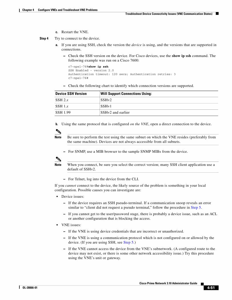
4-51Cisco Prime Network 3.10 Administrator Guide
OL-28066-01
Chapter 4 Configure VNEs and Troubleshoot VNE Problems Troubleshoot Device Connectivity Issues (VNE Communication States)
c. Restart the VNE.
Step 4 Try to connect to the device.
a. If you are using SSH, check the version the device is using, and the versions that are supported in connections.
– Check the SSH version on the device. For Cisco devices, use the show ip ssh command. The following example was run on a Cisco 7600:
c7-npe1-76#show ip sshSSH Enabled - version 2.0Authentication timeout: 120 secs; Authentication retries: 3c7-npe1-76#
– Check the following chart to identify which connection versions are supported.
b. Using the same protocol that is configured on the VNE, open a direct connection to the device.
Note Be sure to perform the test using the same subnet on which the VNE resides (preferably from the same machine). Devices are not always accessible from all subnets.
– For SNMP, use a MIB browser to the sample SNMP MIBs from the device.
Note When you connect, be sure you select the correct version; many SSH client application use a default of SSHv2.
– For Telnet, log into the device from the CLI.
If you cannot connect to the device, the likely source of the problem is something in your local configuration. Possible causes you can investigate are:
• Device issues:
– If the device requires an SSH pseudo-terminal. If a communication snoop reveals an error similar to “client did not request a pseudo terminal,” follow the procedure in Step 5.
– If you cannot get to the user/password stage, there is probably a device issue, such as an ACL or another configuration that is blocking the access.
• VNE issues:
– If the VNE is using device credentials that are incorrect or unauthorized.
– If the VNE is using a communication protocol which is not configured on or allowed by the device. (If you are using SSH, see Step 5.)
– If the VNE cannot access the device from the VNE’s subnetwork. (A configured route to the device may not exist, or there is some other network accessibility issue.) Try this procedure using the VNE’s unit or gateway.
Device SSH Version Will Support Connections Using:
SSH 2.x SSHv2
SSH 1.x SSHv1
SSH 1.99 SSHv2 and earlier

4-52Cisco Prime Network 3.10 Administrator Guide
OL-28066-01
Chapter 4 Configure VNEs and Troubleshoot VNE Problems Troubleshoot Device Modeling Issues (VNE Investigation States)
If you can connect to the device, the likely cause of the problem is that the VNE driver was not correctly implemented. Check the Cisco Bug Toolkit for possible open caveats, or open a bug as explained in Opening a Bug Report, page 4-61.
Step 5 Open an SSH Pseudo-terminal, if required by the device (for example, a snoop can revealed an error similar to “client did not request a pseudo terminal”). Edit the registry so that SSH on the VNE requests a pseudo-terminal:
a. Log into the gateway as pnuser and change to the Main directory.
# cd $ANAHOME/Main
b. Edit the VNE’s registry as follows, where avmxxx is the AVM ID, vne-key is the VNE name, and vne-ip is the VNE P address.
If the VNE is on the gateway server, the unit-IP should be 127.0.0.1.If the VNE is not on the gateway server, the unit-IP should be the unit’s IP address.
# ./runRegTool.sh -gs 127.0.0.1 set unit-IP “avmxxx/agents/da/vne-key/ips/vne-ip/protocols/telnet/connection/explicitly-ask-for-pty” true# ./runRegTool.sh -gs 127.0.0.1 add unit-IP “avmxxx/agents/da/vne-key/ips/vne-ip/protocols/telnet/connection/transport”# ./runRegTool.sh -gs 127.0.0.1 set unit-IP “avmxxx/agents/da/vne-key/ips/vne-ip/protocols/telnet/connection/transport/pty-support” enable# ./runRegTool.sh -gs 127.0.0.1 set unit-IP “avmxxx/agents/da/vne-key/ips/vne-ip/protocols/telnet/telnet-over-sshv1/leadingcrenabled” false# ./runRegTool.sh -gs 127.0.0.1 set unit-IP “avmxxx/agents/da/vne-key/ips/vne-ip/protocols/telnet/telnet-over-sshv2/leadingcrenabled” false
c. Restart the VNE.
If you need more information about protocols and the tests and settings Prime Network uses to determine reachability, see Protocol Reachability Tests, page 12-26.
Troubleshoot Device Modeling Issues (VNE Investigation States)
The Administration and Vision GUI clients provide a Poll Now tool for rediscovering a network element or an NE component. The launch point determines the entity that is rediscovered. If you right-click a device and choose Poll Now, the whole device is rediscovered. If you right-click a device component and choose Poll Now (from the inventory window), only the component is rediscovered. Vision GUI client users must have Operator privileges to use this feature.
Figure 4-14 shows the device inventory window with the Poll Now button at the top left. When launched from this window, the entire device is rediscovered. Although the Poll Now button is provided for use by all VNEs, it is specifically useful for VNEs using reduced polling because it provides a quick way to synchronize the VNE model without having to wait for the next polling cycle.

4-53Cisco Prime Network 3.10 Administrator Guide
OL-28066-01
Chapter 4 Configure VNEs and Troubleshoot VNE Problems Troubleshoot Device Modeling Issues (VNE Investigation States)
Figure 4-14 Poll Now Button in Prime Network Device Inventory
Use this procedure to troubleshoot an unexpected VNE investigation state.
Step Description See:
1 Verify the current VNE investigation (and communication) states in Prime Network Vision.
Step 1: Check the Investigation State, page 4-54
2 Check the investigation state description in the VNE Status Details window, especially if you are seeing the Currently Unsynchronized state. You can optionally check the Service event to see if it can provide any new information.
Step 2: Check the VNE Status Details for the Cause of the Modeling Problem, page 4-57

4-54Cisco Prime Network 3.10 Administrator Guide
OL-28066-01
Chapter 4 Configure VNEs and Troubleshoot VNE Problems Troubleshoot Device Modeling Issues (VNE Investigation States)
Note At any time you can restart the VNE discovery process by restarting the VNE (see Stop, Start, and Move VNEs to Maintenance Mode, page 4-9).
Step 1: Check the Investigation State
Step 1 From the Prime Network Vision map view, double-click the icon in which you are interested. This opens the device properties window.
Note You can launch the device properties window from Prime Network Administration by right-clicking the VNE and choosing Inventory.
Step 2 Check the current Investigation State (as shown in Figure 4-15). The various states are described in Table 4-3, which follows the figure.
3 If needed, perform these additional steps depending on the information you need:
• Verify that all required device configuration tasks have been performed.
• Verify that there are no communication state issues.
• Change Prime Network so that it generates an elaborated report about state changes.
• Get more information to provide to the Cisco Technical Assistance Center.
Step 3: Additional Troubleshooting Steps for Investigation State Problems, page 4-61
Step Description See:

4-55Cisco Prime Network 3.10 Administrator Guide
OL-28066-01
Chapter 4 Configure VNEs and Troubleshoot VNE Problems Troubleshoot Device Modeling Issues (VNE Investigation States)
Figure 4-15 VNE Investigation State (in Prime Network Vision)

4-56Cisco Prime Network 3.10 Administrator Guide
OL-28066-01
Chapter 4 Configure VNEs and Troubleshoot VNE Problems Troubleshoot Device Modeling Issues (VNE Investigation States)
Table 4-11 VNE Investigation States
State Name Description Badge
Defined Not Started
A new VNE was created (and is starting); or an existing VNE was stopped. In this state, the VNE is managed and is validating support for the device type. (This investigation state is the equivalent of the Agent Not Loaded communication state.) A VNE remains in this state until it is started (or restarted). In the VNE Status Details window, the description will say VNE is down.
None
Unsupported The device type is either not supported by Prime Network or is misconfigured (it is using the wrong scheme, or is using reduced polling but the device does not support it). See Table 4-12 on page 4-59 for troubleshooting steps.
Discovering The VNE is building the model of the device (the device type was found and is supported by Cisco Prime Network). A VNE remains in this state until all device commands are successfully executed at least once, or until there is a discovery timeout. In the VNE Status Details window, the description will say Initial investigation of the device.
To troubleshoot a VNE that does not move out of this state, perform the following steps:
1. Verify that all required device configuration tasks have been performed. If they were not, Prime Network cannot properly model the device. See Device Configuration Tasks for Modeling, page A-1.
2. Verify that there are no communication state issues. See Steps to Troubleshoot VNE Communication State Issues, page 4-41. Also see Troubleshoot Device Connectivity Issues (VNE Communication States), page 4-39.
3. Verify that the VNE is using the proper scheme. See Choosing a VNE Scheme (Check Technologies and Device Types), page A-2.
4. Verify that the device is using the proper polling method. See Find Out Whether a VNE is Using Reduced Polling, page 12-6.
The default discovery timeout is 30 minutes but you can adjust it. To change the timeout, see Registry Settings for VNE Discovery Timeout and Investigation State Reporting, page 12-53.
Operational The VNE has a stable model of the device. Modeling may not be fully complete, but there is enough information to monitor the device and make its data available to other applications, such as activation scripts. A VNE remains in this state unless it is stopped or moved to the maintenance state, or there are device errors. In the VNE Status Details window, the description will say Ongoing synchronization with the device.
None
Currently Unsynchronized
The VNE model is inconsistent with the device. This can be due to a variety of reasons; check the VNE Status Details window can provide more information (see Step 2: Check the VNE Status Details for the Cause of the Modeling Problem, page 4-57).

4-57Cisco Prime Network 3.10 Administrator Guide
OL-28066-01
Chapter 4 Configure VNEs and Troubleshoot VNE Problems Troubleshoot Device Modeling Issues (VNE Investigation States)
Step 2: Check the VNE Status Details for the Cause of the Modeling Problem
Step 1 From the VNE properties window (see Figure 4-15 on page 4-55), click VNE Status at the bottom of the properties window to open the VNE Status Details window and check the investigation state information, comparing it against the information in Table 4-12 on page 4-59.
Maintenance VNE polling was suspended because it was manually moved to this state. In the VNE Status Details window, the description will say Device synchronization was suspended by user or system. The VNE remains in this state until it is manually restarted. A VNE in the maintenance state has the following characteristics:
• Does not poll the device, but handles syslogs and traps.
• Maintains the status of any existing links.
• Does not fail on VNE reachability requests.
• Handles events for correlation flow issues. It does not initiate new service alarms, but does receive events from adjacent VNEs, such as in the case of a Link Down alarm.
The VNE is moved to the Stopped state if: it is VNE is moved, the parent AVM is moved or restarted, the parent unit switches to a standby unit, or the gateway is restarted.
Partially Discovered
The VNE model is inconsistent with the device because a required device command failed, even after repeated retries. A common cause of this state is that the device contains an unsupported module. See Table 4-12 on page 4-59 for troubleshooting steps.
Shutting Down The VNE has been stopped or deleted by the user, and the VNE is terminating its connection to the device. The VNE Status Details window, the description will say Device synchronization aborted.
Stopped The VNE process has terminated; it will immediately move to Defined Not Started. None
Table 4-11 VNE Investigation States (continued)
State Name Description Badge

4-58Cisco Prime Network 3.10 Administrator Guide
OL-28066-01
Chapter 4 Configure VNEs and Troubleshoot VNE Problems Troubleshoot Device Modeling Issues (VNE Investigation States)
Figure 4-16 Investigation State Information in VNE Status Details Window

4-59Cisco Prime Network 3.10 Administrator Guide
OL-28066-01
Chapter 4 Configure VNEs and Troubleshoot VNE Problems Troubleshoot Device Modeling Issues (VNE Investigation States)
Table 4-12 VNE Investigation State Information (from VNE Status Details Window)
Field Description
Investigation State VNE investigation state. Basic descriptions of all of the investigation states is provided in Table 4-3 on page 4-8.
Description: Unsupported
The device type is either not supported by Prime Network or is misconfigured (it is using the wrong scheme, or is using reduced polling but the device does not support it). T his is the probable message you will see:
• VNE cannot synchronize with the device—The device type is not supported by Cisco Prime Network (no VNE driver was found for the device). Possible causes:
– The VNE is using the wrong scheme. Verify the device type against the supported schemes in Choosing a VNE Scheme (Check Technologies and Device Types), page A-2.
– The VNE is using the reduced polling method, but the VNE does not support that method. To check whether the device type supports reduced polling, use the procedure described in Find Out Which Device Types Support Reduced Polling, page 12-5.
– Check whether the element is supported in a released device package. See Find Out if New Device Support is Available, page 4-27.
If the device type is not supported:
– You can add the VNE as Generic VNE or ICMP VNE. These VNE types are specified in the VNE General properties; see VNE Properties: General, page D-2.
– You can add the support using the Prime Network VNE Customization Builder. See the Cisco Prime Network 3.10 Customization Guide.

4-60Cisco Prime Network 3.10 Administrator Guide
OL-28066-01
Chapter 4 Configure VNEs and Troubleshoot VNE Problems Troubleshoot Device Modeling Issues (VNE Investigation States)
Description: Currently Unsynchronized
The VNE model is inconsistent with the device. This is often recoverable or may indicate a small inconsistency such as a minor inventory component not being properly modeled. These are some of the messages you may see for this state:
• User initiated device re-synchronization—A user clicked Poll Now in Cisco Prime Network Vision (or issued a BQL command that performs this operation).
• Resuming synchronization after maintenance—The VNE is moving out of a user-induced Maintenance state (a user restarted the VNE).
• Device CPU is high. Synchronization temporarily suspended—The adaptive polling mechanism moved the VNE to this state because the device exceeded its maximum CPU usage threshold. For troubleshooting tips see CPU Utilization Problems: Where to Begin, page 12-2.
• Resuming synchronization after device CPU normalized—The adaptive polling mechanism is moving the VNE back to its normal polling because device CPU usage has stabilized.
• System initiated device resynchronization due to missed device configuration changes—The VNE is using reduced polling and has identified a gap in the configuration log (specifically, the configuration archive buffer), or has failed to identify one or more changes. (VNEs using reduced polling are more sensitive to these changes due to their different polling frequency. For more information, see Reduced Polling, page 12-3.
• VNE cannot reach the device, Synchronization temporarily suspended—The device did not respond in a timely fashion. Follow the troubleshooting steps in Steps to Troubleshoot VNE Communication State Issues, page 4-41.
• Resuming synchronization after device reachability from VNE restored—The VNE is moving out of an unreachable state.
• Temporarily missing or failed VNE driver component—A required, recoverable device command failed. Prime Network retries the command at the next polling cycle, up to 3 retries. (If it fails, the VNE is moved to Partially Discovered.)
• Device synchronization was suspended by system—The system temporarily stopped the synchronization process because it suspects the device was reloaded (this prevents the VNE from collecting irrelevant information). The synchronization process will normally restart within 5 minutes.
The Currently Unsynchronized state can also be caused by a communication state issue. See Steps to Troubleshoot VNE Communication State Issues, page 4-41.
Description: Partially Discovered
Missing or failed VNE driver component—Prime Network could not recognize an element in the device. Consider the following troubleshooting options:
• Check whether the element is supported in a released device package. See Find Out if New Device Support is Available, page 4-27.
• To extend Cisco Prime Network functionality so that it recognizes unsupported parts of devices, use the VNE Customization Builder. See the Cisco Prime Network 3.10 Customization Guide.
Reduced Polling Reports whether VNE is using reduced polling mechanism to control polling (true=enabled). Reduced polling means polling is performed only when a poll-worthy event is received from device, thus reducing the overall polling (true if enabled, false if disabled). For information on the reduced polling mechanism, see Reduced Polling, page 12-3.
Since Timestamp of when the state information was last updated.
For information on the communication state details that are provided in this window, see Table 4-10 on page 4-45.
Table 4-12 VNE Investigation State Information (from VNE Status Details Window) (continued)
Field Description

4-61Cisco Prime Network 3.10 Administrator Guide
OL-28066-01
Chapter 4 Configure VNEs and Troubleshoot VNE Problems Troubleshoot Device Modeling Issues (VNE Investigation States)
Step 2 Optionally, check the System event in Prime Network Events to see if it can provide additional information.
Note Keep in mind that if an AVM or unit crashes, Prime Network will not generate a Service event for the communication state change, because event-generating entity (the AVM or unit) is itself down. However, the GUI will display the VNE/Agent Unreachable icon. Any tickets related to the problem (that were sent before the crash) will remain open until the VNE restarts and generates a clearing event. If no related tickets were sent before the crash, check Prime Network Events for other related information.
Step 3: Additional Troubleshooting Steps for Investigation State Problems
Step 1 Verify that all required device configuration tasks have been performed. If they were not, Prime Network cannot properly model the device. See Device Configuration Tasks for Modeling, page A-1.
Step 2 Verify that there are no communication state issues; specifically, check for a System event in Prime Network Vision. The problem may be due to the fact that the device did not respond in a timely manner.
Step 3 Optionally perform the following tasks:
• Adjust the registry setting so that Prime Network Events generates an elaborated report about state changes. See Table 4-12 on page 4-59.
• Open the device properties window in Prime Network Vision. Place your cursor in the inventory window, and press F2. Click Managed State Aspect and review the information. This information is especially useful when working with the Cisco Technical Assistance Center.
Opening a Bug ReportAfter performing the troubleshooting steps in the previous sections, if you still have a problem, you may consider opening a bug (or enhancement request).
Before You Open a Bug
1. Verify that the network element, event, etc. is supported by checking these documents:
– The lists of supported VNEs and events on Cisco.com
– Addendum: Additional VNE Driver Support for Cisco Prime Network 3.10 (this document is released when the first DP becomes available; see Add New Device Support by Installing Device Packages, page 4-26.
Note If the device is not supported, you can add the support using the Prime Network VNE Customization Builder. See Cisco Prime Network 3.10 Customization Guide. Also, this guide contains an extended procedure for finding out which traps and syslogs are not supported and how to troubleshoot them.
4-62Cisco Prime Network 3.10 Administrator Guide
OL-28066-01
Chapter 4 Configure VNEs and Troubleshoot VNE Problems Track VNE-Related Events
2. Make sure you have tried all of the troubleshooting steps provided in these topics:
– Troubleshoot Device Connectivity Issues (VNE Communication States), page 4-39
– Steps to Troubleshoot VNE Communication State Issues, page 4-41
– Troubleshoot Device Modeling Issues (VNE Investigation States), page 4-52
3. Provide all of the necessary details for the bug report (reproduce the problem if necessary).
Information You Must Provide
1. Describe the actual behavior versus the expected behavior. For example, “Module serial numbers are missing from Vision.”
2. Describe how to recreate the error scenario.
3. Provide the following device details:
– Device type.
– Device operating system (including service and patches applied on the NE).
– Device configuration information. If possible, attach a running config.
– For device physical modeling issues, details on the physical module.
– For device logical modeling issues, details on the service.
4. Collect the following Prime Network information:
– Pertinent AVM log files from NETWORKHOME/Main/logs.
– List of VNE drivers that are installed.
– Prime Network version. From the gateway, run networkctl status and note the version and build number that are displayed at the top of the status message.
– Patch level details. You can use this command:
checkPatchInstallation.pl -v -p
5. For physical model issues, provide screen captures (of the Prime Network GUI clients and the EMS) that show the discrepancies.
6. For NBI-related issues, provide the IMO or BQL citation.
Track VNE-Related EventsWhen you audit VNE behavior, you are checking the backend process that models and monitors a device in the network. The following table provides ways you can get historical information on VNE-related events. You can tailor your search or reports by specifying keywords (such as VNE).
Information Type Refer to:
Recent System and Security events System and Security tabs in Event GUI client
Historical data on System and Security events for a specific time period and/or specific events
From the main menu, choose Reports > Run Report > Events Reports > Detailed Non-Network Events

4-63Cisco Prime Network 3.10 Administrator Guide
OL-28066-01
Chapter 4 Configure VNEs and Troubleshoot VNE Problems Track VNE-Related Events

4-64Cisco Prime Network 3.10 Administrator Guide
OL-28066-01
Chapter 4 Configure VNEs and Troubleshoot VNE Problems Track VNE-Related Events

C H A P T E R
5-1Cisco Prime Network 3.10 Administrator Guide
OL-28066-01
5Manage Redundancy for Units and Processes
The unit server high availability and AVM protections architecture ensures continuous availability of Prime Network functionality by detecting and recovering from a wide range of hardware and software failures. The distributed design of the system enables the impact radius caused by a single fault to be confined. This prevents all types of faults from setting into motion the “domino” effect, which can lead to a crash of all the management services.
These topics describes how you can use Prime Network for unit redundancy and process protection:
• Overview of Unit and Process Protection, page 5-1
• What is the Impact of Unit or AVM Failures?, page 5-3
• Create a New Unit Protection Group, page 5-9
• Switch to a Standby Unit (Disable Active Unit), page 5-9
• Change Timeouts and Restarts for Unit and Process Protection, page 5-10
• Track Unit and Process Protection Events, page 5-11
For information on high availability for gateway servers, see Cisco Prime Network 3.10 Gateway High Availability Guide.
Overview of Unit and Process ProtectionThe following topics explain the process (AVM) protection and unit high availability features provided by Prime Network. Most of these settings are enabled by default. When you create an AVM, AVM process protection is automatically enabled. When units are created during installation, you specify whether they will be standby or active units. Units are automatically added to the protection group default-pg.
Process (AVM) Protection
The AVM protection mechanism monitors AVM processes to make sure any failed AVMs are restarted. Protection is normally enabled by default and is controlled by way of the AVM Protection check box in the AVM properties dialog box.
All AVM processes within a unit are completely independent so that a failure of a single process does not affect other processes on the same machine. The exact number of processes on each unit depends on the capacity and computational power of the unit.

5-2Cisco Prime Network 3.10 Administrator Guide
OL-28066-01
Chapter 5 Manage Redundancy for Units and Processes Overview of Unit and Process Protection
On the unit, a control process starts the watchdog protocol which continuously monitors all other processes on the unit. The watchdog protocol requires each AVM process to continuously handshake with the control process. A process that fails to handshake with the control process after a number of times is automatically cancelled and reloaded.
The unit control process monitors AVM restarts and will escalate the issue, according to the system settings. For example, if a process has crashed more than n times within a given period, Prime Network will no longer attempt to restart it because it is suspected of having a recurring software problem.
The reload process is local to the unit, and thus very rapid, with a minimal amount of downtime. In many cases the process can use its previous cache information (temporary persistency used to improve performance), once the stuck process id detected, reloading the process takes only a few seconds with no data loss. This is the case for user-created AVMs that are hosting VNEs. However, for reserved AVMs that perform special function in Prime Network, some data loss will occur. All watchdog activity is logged and an alarm is generated and sent when the watchdog reloads a process.
Note An alarm persistency mechanism enables the system to clear alarms that relate to events that occurred while a VNE, an AVM, a unit, or the whole system was down, thus preserving system integrity. For more information about alarm persistency, see Change Settings That Control VNE Data Saved After Restarts, page 12-36
Watchdog protocol parameters are configurable in the registry. See Change Timeouts and Restarts for Unit and Process Protection, page 5-10.
Unit N+m High Availability
Unit availability is established in the gateway, running a protection manager process, which continuously monitors all the units in the network. Once the protection manager detects a unit that is malfunctioning, it automatically signals one of the standby servers in its cluster to load the configuration of the faulty unit (from the system registry), taking over all of its managed network elements. This design provides many possibilities for trading off protection and resources. These possibilities range from segmenting the network into clusters without any extra machines, to having a warm-swappable empty unit for each unit in the setup.
When the Prime Network software is installed, you can specify whether a unit is an active or standby unit. Using the GUI, you can designate a group of active units and a standby unit to be the members of a protection group, giving the group the name of your choice. A protection group can have multiple standby units, and you can define more than a single protection group. By default, all units are added to the default-pg protection group.
Even with unit redundancy, a unit switchover can result in the unavoidable loss of information. The impact depends on how long the unit is down and the functions the unit performed. See Impact of Unit Timeouts and Switchovers, page 5-7, for more information.
Figure 5-1 shows a protection group (cluster) of units controlled by a gateway with one unit configured as the standby for the protection group.
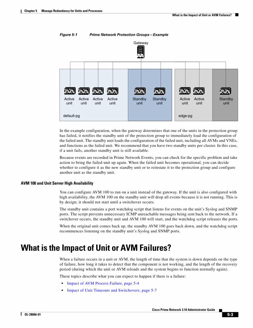
5-3Cisco Prime Network 3.10 Administrator Guide
OL-28066-01
Chapter 5 Manage Redundancy for Units and Processes What is the Impact of Unit or AVM Failures?
Figure 5-1 Prime Network Protection Groups—Example
In the example configuration, when the gateway determines that one of the units in the protection group has failed, it notifies the standby unit of the protection group to immediately load the configuration of the failed unit. The standby unit loads the configuration of the failed unit, including all AVMs and VNEs, and functions as the failed unit. We recommend that you have two standby units per cluster. In this case, if a unit fails, another standby unit is still available.
Because events are recorded in Prime Network Events, you can check for the specific problem and take action to bring the failed unit up again. When the failed unit becomes operational, you can decide whether to configure it as the new standby unit or to reinstate it to the protection group and configure another unit as the standby unit.
AVM 100 and Unit Server High Availability
You can configure AVM 100 to run on a unit instead of the gateway. If the unit is also configured with high availability, the AVM 100 on the standby unit will drop all events because it is not running. This is by design; it should not start until a switchover occurs.
The standby unit contains a port watchdog script that listens for events on the unit’s Syslog and SNMP ports. The script prevents unnecessary ICMP unreachable messages being sent back to the network. If a switchover occurs, the standby unit and AVM 100 will start, and the watchdog script releases the ports.
When the original unit comes back up, the standby AVM 100 goes back down, and the watchdog script recommences listening on the standby unit’s Syslog and SNMP ports.
What is the Impact of Unit or AVM Failures?When a failure occurs in a unit or AVM, the length of time that the system is down depends on the type of failure, how long it takes to detect that the component is not working, and the length of the recovery period (during which the unit or AVM reloads and the system begins to function normally again).
These topics describe what you can expect to happen if there is a failure:
• Impact of AVM Process Failure, page 5-4
• Impact of Unit Timeouts and Switchovers, page 5-7
Gateway
default-pg edge-pg
Activeunit
Activeunit
Activeunit
Activeunit
Standbyunit
Activeunit
Activeunit
Standbyunit
Standbyunit

5-4Cisco Prime Network 3.10 Administrator Guide
OL-28066-01
Chapter 5 Manage Redundancy for Units and Processes What is the Impact of Unit or AVM Failures?
Impact of AVM Process Failure
These topics explain the impact of two very different failure scenarios—when individual AVMs are stopping and restarting, and when there is a catastrophic failure.
• Impact of AVM Timeouts and Restarts, page 5-4
• Impact of Catastrophic AVM Process Failure, page 5-5
Impact of AVM Timeouts and Restarts
Each AVM is constantly monitored by the management AVM (AVM 99) using a watchdog protocol pulse message sent to the AVM at preconfigured intervals. When the AVM fails to respond to the pulse message after a preconfigured number of attempts, the management AVM restarts the process.
The management process also keeps a history of the number of times it has restarted the AVM. When it reaches the maximum number of preconfigured restart times, the management AVM stops restarting the AVM because this indicates a serious problem with the AVM. Each restart is logged as a System event (except when AVM 11 is restarted, because this AVM handles all persistency).
Failures on AVMs in the system are measured in a way similar to that used for catastrophic process failures (see Table 5-1), with the addition of the watchdog protocol overhead. This is measured by the pulse interval multiplied by the number of restart attempts.
Keep the following in mind when evaluating an AVM failure:
• The maximum number of preconfigured restart times is five, after which the management process does not try to reload the AVM.
• It takes approximately one minute for the system to detect that an AVM (including AVM 100) is not working.
• The recovery period during which an AVM (including AVM 100) reloads and the system starts to function normally again is approximately five minutes, depending on the number of VNEs per AVM and the complexity of each.
Figure 5-2 provides a typical example of how unit server high availability timer parameters work while monitoring AVMs.
Note If you are using gateway server high availability, there is no overlapping between the processes that AVM 99 monitors that are illustrated in Figure 5-2, and the process that the gateway high availability software monitors.

5-5Cisco Prime Network 3.10 Administrator Guide
OL-28066-01
Chapter 5 Manage Redundancy for Units and Processes What is the Impact of Unit or AVM Failures?
Figure 5-2 Unit Server High Availability Parameter Timers and AVM Monitoring Example
Measuring Fault-Processing Down Time for AVMs
When a failure occurs on an AVM, the time during which ticket processing is down is measured as the sum of the following factors:
• The time it takes to determine that the AVM has failed.
• The time it takes for the AVM to reload, depending on the number of VNEs.
• The time it takes to pass syslogs or traps to the VNEs (in the case of AVM 100), or to pass events to the gateway (in the case of AVM 101-999).
Note For the first 30 minutes after AVM 99 (the management AVM) has started, there is no monitoring of the system to find unit server high availability issues. This allows the system enough time to get up and running.
Impact of Catastrophic AVM Process Failure
Each AVM has a log file which is constantly monitored by a Perl process for log messages about catastrophic failures, such as AVM processes running out of memory. When such a failure occurs, the Perl process restarts the AVM almost immediately, so the mean time to repair (MTTR) is based on the AVM loading life cycle.
Table 5-1 describes the impact on different AVMs when experiencing such a failure.
Gateway A(Active)
Gateway B(Standby)
Unit B(Backup)
Unit A(Active)
AVM99
AVM11
AVM99
AVM11 AVM101
AVM0 AVM66
AVM100
VNE A
AVM99 to AVM100Pings every 60 secWaits for response 5 minAdjustments to wait-timerare not recommended
AVM99 to AVM11Pings every 60 secWaits for response 5 minAdjustments to wait-timerare not recommended
AVM11 to AVM99Pings every 60 secWaits for response 5 minWait-timer is adjustable (0-15)
AVM99 to AVM101Pings every 60 secWaits for response 5 minAdjustments to wait-timerare not recommended
Protection Group A/B
2367
88

5-6Cisco Prime Network 3.10 Administrator Guide
OL-28066-01
Chapter 5 Manage Redundancy for Units and Processes What is the Impact of Unit or AVM Failures?
Table 5-1 Catastrophic Process Failure Impact on AVMs
AVM Process Results of AVM FailureAverage Time To Repair Failed AVM Degree of Impact to System if AVM Fails
AVM 0 (High availability/switch)
Loss of messages to and from the machine.
1 minute to reach bootstrap. High. Messages are constantly being sent and received in the system.
AVM 11 (Gateway)
Loss of persistence information for faults (except for the I persistency information handled by AVM 25 and AVM 100). No user authentication will be performed on gateway connections, and GUI clients will lose gateway connectivity.
6-10 minutes to reach bootstrap.
High. AVM 11 handles Oracle communication and various gateway functions such as alarm processing.
AVM 25 (Event persistence)
Loss of persistence information and new tickets for actionable network events that are processed while AVM 25 is down. When it comes up, new events that correlate to “lost” events will be persisted but will not be associated with a ticket until the integrity process identifies the broken chains (due to lost events) and opens new tickets.
1 minute to reach bootstrap. High. Network events are constantly processed in a live, scaled system.
AVM 35 (Service discovery)
Network services displayed on maps (such as Ethernet service and MPLS-TP) are not updated to reflect network changes.
1 minute to reach bootstrap, plus several minutes to redisplay already discovered services, plus time required to detect changes that occurred when the AVM was down (30 minutes to 10 hours, depending on number, type, services, etc.).
Low: Network services display would be updated after a discovery resynch process is finished.
AVM 66 (Workflow engine)
Running workflows would abort and scheduled workflows would not run. Templates would not be deployed.
1 minute to reach bootstrap, but with large number of workflows in the system, this may increase.
Low, because AVM 66 should sustain a large number of executed workflows (per the system limitations). Templates would need to be redeployed and aborted workflows would need to be rerun. Check the Provisioning events in Prime Network Events to verify what ran prior to failure, and then issue an rollback (no automatic rollback is done).
AVM 76 (Job scheduler)
No jobs can be added, executed, or removed.
1 minute to reach bootstrap. Depends on job types.

5-7Cisco Prime Network 3.10 Administrator Guide
OL-28066-01
Chapter 5 Manage Redundancy for Units and Processes What is the Impact of Unit or AVM Failures?
Impact of Unit Timeouts and Switchovers
The Prime Network gateway constantly monitors units by sending a watchdog protocol pulse message to the unit management AVM at preconfigured intervals. If the unit management AVM fails to respond to the pulse message after a preconfigured number of retries, the gateway loads the standby unit to replace it.
AVM 77 (Change and Configuration Management)
Loss of device configuration changes. Configuration changes will not be backed up to the archive during down time.
10 minutes for DM server startup and bundle deployment, plus time to fetch all configurations for managed devices.
High (if using Change and Configuration Management); because configuration change notifications can happen all the time.
AVM 78 (VNE topology)
Topology links between VNEs on different units will not discovered.
1 minute to reach bootstrap. Low; there may be some missing topology links.
AVM 83 (TFTP server for Change and Configuration Management)
Change and configuration management TFTP operations will fail. (Operations using secure protocol or FTP will not be affected.)
5 minutes. High (if using Change and Configuration Management); Change and Configuration Management device properties would fail.
AVM 84 (Reports)
Loss of reports.When AVM 84 is down running reports will fail.
1 minute. Low; reports would need to be rerun.
AVM 99 (Management)
Loss of registry notifications on changes made to golden source registry.
1 minute to reach bootstrap. Low, because registry modifications are made only when the VNE is first loaded into the system. Modifications are rarely made while the system is up and running.
For the first 30 minutes after AVM 99 has started, there is no system monitoring for unit server high availability. This allows the system enough time to get up and running
AVM 100(Event Collector)
Loss of traps and syslogs from devices, including raw event persistency.
1 minute to reach bootstrap, plus time for all the VNEs to register again for traps and syslogs. Normally a matter of minutes.
High, because raw events from devices are constantly received in a live, scaled system. Only devices registered to the failed AVM 100 are affected. No events will be handled during downtime. See AVM 100 and Unit Server High Availability, page 5-3. (Raw event persistency is recovered before events are forwarded to the VNEs.)
AVM 101-999 (User-defined AVMs)
Loss of management to a section of devices managed by the AVM; alarm state inconsistencies (user will have to clear tickets).
1 minute to reach bootstrap, plus time to load the VNEs (depending on number, type, services, etc.).
High (but only for a period of one minute), because no raw events sent to the VNEs can be processed when the AVM is down.
Table 5-1 Catastrophic Process Failure Impact on AVMs (continued)
AVM Process Results of AVM FailureAverage Time To Repair Failed AVM Degree of Impact to System if AVM Fails

5-8Cisco Prime Network 3.10 Administrator Guide
OL-28066-01
Chapter 5 Manage Redundancy for Units and Processes What is the Impact of Unit or AVM Failures?
The impact of such a failure on the system is that the unresponsive unit does not manage the devices for a period of time. This unmanaged period of time is measured by the pulse interval multiplied by the number of retry times, plus the unit load time.
Note Unit load time depends on the configuration of the unit—the hardware, the number of VNEs, the types of VNEs, and the services running on the VNEs. All of these factors impact the load time required for the VNEs to complete their modeling, as described in Table 5-1.
(On the other hand, if the problematic unit has not completely failed and continues to operate after the switchover, you may see duplicate events in the database. In this case you should stop the original problematic unit using networkctl stop.)
Figure 5-3 illustrates how a unit handles events during the loading time for units, AVMs, and VNEs.
Figure 5-3 Stages in Event Handling Through System Restart
Measuring Ticket-Processing Down Time for Units
When a failure occurs on a unit, the time during which ticket processing is down is measured as the sum of the following factors:
• The time it takes to determine that the unit has failed (depending on the ping interval).
• The time it takes for the unit to reload, depending on the number of AVMs and VNEs in the unit.
• The time it takes to pass correlated events to the gateway (a minimum of five minutes to obtain device history, plus a variable time depending on the number of VNEs per AVM).

5-9Cisco Prime Network 3.10 Administrator Guide
OL-28066-01
Chapter 5 Manage Redundancy for Units and Processes Create a New Unit Protection Group
Create a New Unit Protection GroupNew units are added to Prime Network during installation as described in the Cisco Prime Network 3.10 Installation Guide. During installation, you can specify whether the unit is a standby unit, and which protection group the unit should belong to (the default is default-pg).
Before You Begin
Keep the following guidelines in mind when configuring protection groups:
• Design protection groups according to geography.
• Add an additional standby unit to heavily-loaded groups.
• Do not assign active and standby units to more than one group.
• Units in a group must have the same operating system. If any unit has a database connection, all other units must also have a connection.
To create or edit a protection group:
Step 1 Create the new protection group.
a. Choose Global Settings > Protection Groups.
b. Open the New Protection Group dialog box by right-clicking Protection Groups, then choose New Protection Group. For an existing group, right-click the group and choose Properties.
c. Enter a name and description, or edit the description.
d. Click OK. The content area displays details of the new protection group and all currently defined protection groups in the Protection Groups table.
Step 2 Add units to the new protection group.
a. Right-click the unit and select Properties.
b. In the Protection Group drop-down list, select the new protection group and click OK.
Switch to a Standby Unit (Disable Active Unit)Prime Network will automatically switch over to a standby unit occurs when the gateway discovers that one of the active units has failed. Such failures include hardware failures, operating system failures, power failures, and network failures, which disconnect a unit from the Prime Network fabric. If the protection group has more than one standby unit, Prime Network randomly selects the standby unit.
Note If the problematic unit has not completely failed and continues to operate after the switchover, you may see duplicate events in the database. In this case you should stop the original problematic unit using networkctl stop.
You can also perform a manual switchover to a standby unit (for example, if you have to shut down the unit for maintenance).
When a switchover occurs, Prime Network automatically transfers all data from the failed unit to a standby unit in the same protection group. The original unit is removed from the standby setup and is no longer displayed in Prime Network Administration.

5-10Cisco Prime Network 3.10 Administrator Guide
OL-28066-01
Chapter 5 Manage Redundancy for Units and Processes Change Timeouts and Restarts for Unit and Process Protection
Note When a unit switches to its standby, all VNEs on the unit that were in maintenance mode will be moved to the VNE Down state.
To manually switch to a standby unit:
Step 1 Expand the All Servers branch and select the required unit.
Step 2 Right-click the required unit, then choose Switch. A confirmation message is displayed.
Step 3 Click Yes. The standby unit becomes the active unit and is displayed in the All Servers branch. The original unit is removed from the setup and can be safely shut down. It is no longer displayed in the All Servers branch in the navigation tree.
Change Timeouts and Restarts for Unit and Process ProtectionThe AVM process and unit protection functions are controlled by settings in the registry. The registry entries and default values are provided in Table 5-2.
Caution Increasing these values allows AVM or unit failures to last longer, but it also increases the certainty that a failure has actually occurred. However, decreasing these values can result in a “false positive.” In other words, the shorter allowable AVM or unit failure period can result in unnecessary AVM restarts or unit switchovers when an AVM or unit is simply busy processing a large amount of data.
Table 5-2 Registry Settings for Unit Server High Availability and AVM Watchdog Protocol
Registry Entry Description Default Value
agent_defaults/delay Grace period (in milliseconds) during which events are not raised. This defines the amount of time during which the system does not perform high availability operations of any kind on the configured target (either the AVM or the unit). The grace period begins at system startup. The only exception is when the configured target responds for the first time with a ping; at that point the grace period is over.
1800000 (30 minutes)
agent_defaults/timeout AVMs recovery period (in milliseconds). This period includes device polling and inventory buildup. (End-to-end services, such as RCA and topology, can take longer before they become available.)
300000 (5 minutes)
haservice/timeout Units recovery period (in milliseconds). 300000 (5 minutes)
agent_defaults/maxTimeoutReloadTime Threshold for permitted AVM retries (in milliseconds). When exceeded, the AVM is suspended.
1800000 (180 minutes)
agent_defaults/maxTimeoutReloadTries Maximum number of AVM retries. When exceeded, the AVM is suspended.
5

5-11Cisco Prime Network 3.10 Administrator Guide
OL-28066-01
Chapter 5 Manage Redundancy for Units and Processes Track Unit and Process Protection Events
Track Unit and Process Protection EventsThe following table provides ways you can get historical information on unit high availability and AVM process protection events. You can tailor your search or reports by specifying keywords (switchover, high availability, watchdog protocol, and so forth).
Information Type Refer to:
Recent System and Security events System and Security tabs in Event GUI client
Historical data on System and Security events for a specific time period and/or specific events
From the main menu, choose Reports > Run Report > Events Reports > Detailed Non-Network Events

5-12Cisco Prime Network 3.10 Administrator Guide
OL-28066-01
Chapter 5 Manage Redundancy for Units and Processes Track Unit and Process Protection Events
C H A P T E R
6-1Cisco Prime Network 3.10 Administrator Guide
OL-28066-01
6Control Device Access Using Device Scopes
These topics describe how to create and manage device scopes. Device scopes determine the devices a user can access, and the actions the user can perform on the devices. The same device scope can be applied to multiple user accounts, but you can specify more or less strict privileges on a per-user basis.
Note Device scopes are disabled if Prime Network is installed with Cisco Prime Central.
• What Are Device Scopes?, page 6-1
• Create New Device Scopes, page 6-3
• View Links When Only One Endpoint is in Scope, page 6-4
• Move Devices In and Out of a Scope, page 6-5
• Change a User’s Device Scope Security Level, page 6-5
• Delete a Device Scope from Prime Network, page 6-6
• Track Device Scope Events, page 6-6
What Are Device Scopes?
Note Device scopes are disabled if Prime Network is installed with Cisco Prime Central.
In Prime Network, user roles and device scopes determine which tasks a user can perform. A user role is specified when you create the user’s account. The user role determines the GUI-based actions the user can perform.
The actions a user can perform on a device are controlled by device scopes. Device scopes are groups of devices that you assign to users. If a device is in a scope that is assigned to a user, then the user can access the device. Device scopes are listed in the Administration GUI client when you choose Scopes in the navigation tree.
This topic does not address authentication—that is, the process of verifying the identity of the user. For information on user authentication, see User Authentication, page 7-2.
When you create a new device scope, you specify a name for the scope and which devices to include in the scope (as many or as few as you want). This allows you to group devices in a way that fits your deployment—for example, by geography, by device type, by customer, and so forth. However, just

6-2Cisco Prime Network 3.10 Administrator Guide
OL-28066-01
Chapter 6 Control Device Access Using Device Scopes What Are Device Scopes?
because a user has access to a device does not mean they can perform all actions on the device. When you assign a device scope to a user, you also specify the security level for that scope. In this way, you control the devices a user can access, and what actions the user can perform on those devices.
Creating scopes and assigning them to users is controlled from the Administration GUI client. If you create an account for a user but do not assign any device scopes to the account, the user will be able to open Prime Network but will not see any devices.
Figure 6-1 shows an example of the Prime Network Administration Scopes window.
Figure 6-1 Scopes Window
Severity levels for device scopes can override GUI user access roles. For example:
1. John’s user access role (for GUI operations) is Operator.
2. John’s security level for the device scope CE-SJ is Configurator.
Prime Network will allow John to perform Configurator operations on any devices in the CE-SJ device scope.
The All Managed Elements Device Scope
The All Managed Elements device scope is a predefined scope that is automatically assigned to users with Administrator privileges. It contains all NEs that are managed by Prime Network and has a security level named Special. The Special security level only applies to this device scope, and only when the scope is assigned to Administrators.
New devices are automatically added to the All Managed Elements device scope when the VNEs are created.
Note You can edit the scope to have less privileges, or even delete it completely, but this is not recommended. It would result in Administrators only having access to GUI functions that do not affect devices.
You are permitted to assign the All Managed Elements device scope to non-Administrators, but you can only apply a security level of Configurator or less.

6-3Cisco Prime Network 3.10 Administrator Guide
OL-28066-01
Chapter 6 Control Device Access Using Device Scopes Create New Device Scopes
Table 6-1 lists the device-based actions a user can perform, based on the device scope security level.
Note Users with higher user roles can perform all the actions for which lower roles are authorized. For example, the Configurator is authorized to perform all the actions that the Viewer, Operator, and OperatorPlus can perform.
Create New Device Scopes
Note Device scopes are disabled if Prime Network is installed with Cisco Prime Central.
Before you create a scope, consider the following:
• Which devices a user (or group of users) should be allowed to access
• The security level (user access role) that should be applied to the devices in the scope. (Remember security levels can override user access roles. For example, if a user has an Operator access role and a Configurator scope security level, the user will be allowed to perform Configurator-level operations on the devices in the scope.)
When you create a device scope, you must give it a name and choose the devices to include in the scope. When you assign a scope to a user, you adjust the security level to be more or less strict.
Table 6-1 Comparison of Permitted Actions for Device Scope and GUI Client Based on Security Level/User Role
Security Level/ User Role
Device Based (Scope) Actions Permitted to Users with This Role GUI Client Actions Permitted to Users with This Role
Administrator All actions. All actions.
Configurator Activation services: Add and publish activation commands on managed NE (regardless of whether the NE is inside or outside the Configurator’s scope).
Maps: Create maps.
Advanced tools: Ping and Telnet an NE directly from the GUI client; enable and disable port alarms; create commands using Command Builder.
OperatorPlus Maps: Create business tags for NEs.
Network information: Display include path tool traffic, rates, drops, or any dynamic data.
Maps: Create new maps and add NEs; edit, delete, rename, and save maps; create and break aggregations; change map layout and set background image; create business links.
Operator Network information: Refresh port information from NE.
Maps: Create and delete business tags for NEs.
Viewer Network and business tag information: View alarm list and alarm properties, and find alarms; find and view attachments; view NE properties and inventory; calculate and view affected parties; open port utilization graphs.
Application: Log into the Vision GUI client; change their password (local authentication); view the device list and map; view link properties; use table filters and export data from tables.

6-4Cisco Prime Network 3.10 Administrator Guide
OL-28066-01
Chapter 6 Control Device Access Using Device Scopes View Links When Only One Endpoint is in Scope
Note By default, users can only view links if both endpoints are in this scope. If you want to change this setting so that only one link endpoint is required, see View Links When Only One Endpoint is in Scope, page 6-4.
To create a scope:
Step 1 Right-click Scopes and choose New Scope to open the New Scope dialog box.
Step 2 In the Scope field, enter a name for the scope.
Step 3 Add devices to the scope by selecting them from the Available Devices list and moving them to the Selected Devices list.
Step 4 Click OK. The scope is saved and is displayed in the content area.
View Links When Only One Endpoint is in Scope
Note Device scopes are disabled if Prime Network is installed with Cisco Prime Central.
By default, a user can view a link in Prime Network Vision only if both link endpoints are in the user’s device scope. If you want to make links viewable if only one endpoint is in a user’s scope, you must edit the registry as follows. Changes are applied to all device scopes in the system.
Note This procedure requires a gateway restart.
Step 1 Log into the gateway as pnuser and change to the NETWORKHOME/Main directory:
# cd $ANAHOME/Main
Step 2 To check the current setting, run the following command (which is one line):
# ./runRegTool.sh -gs 127.0.0.1 get 0.0.0.0 “site/mmvm/services/securitymanager/linkoid-by-any-side”
A return of false means it is set to the default; that is, both links must be in a user’s scope to be viewable.
Step 3 To change the setting so that only one link endpoint is required, run the following command (which is one line):
# ./runRegTool.sh -gs 127.0.0.1 set 0.0.0.0 “site/mmvm/services/securitymanager/linkoid-by-any-side” true
Step 4 When the gateway server returns a success message, restart it.

6-5Cisco Prime Network 3.10 Administrator Guide
OL-28066-01
Chapter 6 Control Device Access Using Device Scopes Move Devices In and Out of a Scope
Move Devices In and Out of a Scope
Note Device scopes are disabled if Prime Network is installed with Cisco Prime Central.
Caution Changes you make to an existing device scope are applied to all users with access to the scope.
To add or remove devices from a scope:
Step 1 Select Scopes to populate the list of existing scopes.
Step 2 Right-click a scope and choose Properties.
Step 3 Modify the scope device list by selecting them from the Available Devices list and moving them to the Selected Devices list.
Note You can select multiple devices by using the Ctrl key.
Step 4 Click OK. The scope is updated and is displayed in the content area.
Change a User’s Device Scope Security Level
Note These features are disabled if Prime Network is installed with Cisco Prime Central.
This procedure explains how to change the security level for a device scope. This is done from the user accounts dialog box. When you change the security level, it only affects this user. (Scopes do not have a default security level; the security level is set when the scope is added to a user account.)
Step 1 Select Users to populate the list of existing user accounts.
Step 2 Right-click a user account and choose Properties to open the user properties dialog box.
Step 3 Click the Authorization tab.
Step 4 In the Device Security area, highlight the scope you want to edit and click Edit. (You can choose several scopes at a time, if desired.)
To make this device scope change... Do the following:
Change the device membership Follow the procedure in this topic.
Change the name Create a new scope. You cannot change an existing scope’s name.
Change the security level Edit the security level in the user’s account. See Change a User’s Device Scope Security Level, page 6-5

6-6Cisco Prime Network 3.10 Administrator Guide
OL-28066-01
Chapter 6 Control Device Access Using Device Scopes Delete a Device Scope from Prime Network
Step 5 In the Edit Scope dialog, make sure the correct scope is highlighted, and click the new security level.
Step 6 Click OK and Apply.
Delete a Device Scope from Prime Network
Note Device scopes are disabled if Prime Network is installed with Cisco Prime Central.
Caution When you delete a scope using this procedure, the scope is removed from all user accounts it was assigned to.
To delete a scope:
Step 1 Select Scopes in the navigation pane.
Step 2 Right-click the scope you want to remove, then choose Delete.
Note You can select multiple scopes by using the Ctrl key.
The scope is deleted and is removed from the content area.
Track Device Scope EventsThe following table provides ways you can get historical information on device scope-related events. You can tailor your search or reports by specifying keywords (such as scope).
Information Type Refer to:
Recent System events System tab in Event GUI client
Historical data on System events for a specific time period and/or specific events
From the main menu, choose Reports > Run Report > Events Reports > Detailed Non-Network Events > System Events

C H A P T E R
7-1Cisco Prime Network 3.10 Administrator Guide
OL-28066-01
7Manage User Accounts
Note User authentication and authorization by Prime Network is disabled if Prime Network is installed with Cisco Prime Central.
User account settings determine the actions users can perform in Prime Network. Each user has an access role that determines the GUI-based tasks they can perform. Device-based tasks are determined by the device scopes that are applied to a user’s account, and the privileges they have for that scope. You can also control which maps users can access.
These topics explain how to create and manage user accounts. These topics also explain how to change global password rules and how to change the default access role required to log into the Events GUI client.
• User Authentication and Authorization Overview, page 7-2
• Check Existing User Accounts, page 7-4
• Configure Global User Settings, page 7-5
• Change GUI Client User Passwords, page 7-8
• Create a New User Account and View User Properties, page 7-9
• Change the User Access Role for the Events GUI Client, page 7-13
• Configure External User Authentication (LDAP), page 7-14
• Control User Access to Maps, page 7-22
• Unlock and Re-enable User Accounts, page 7-23
• Delete a Prime Network User Account, page 7-24
• Track User-Related Events, page 7-24
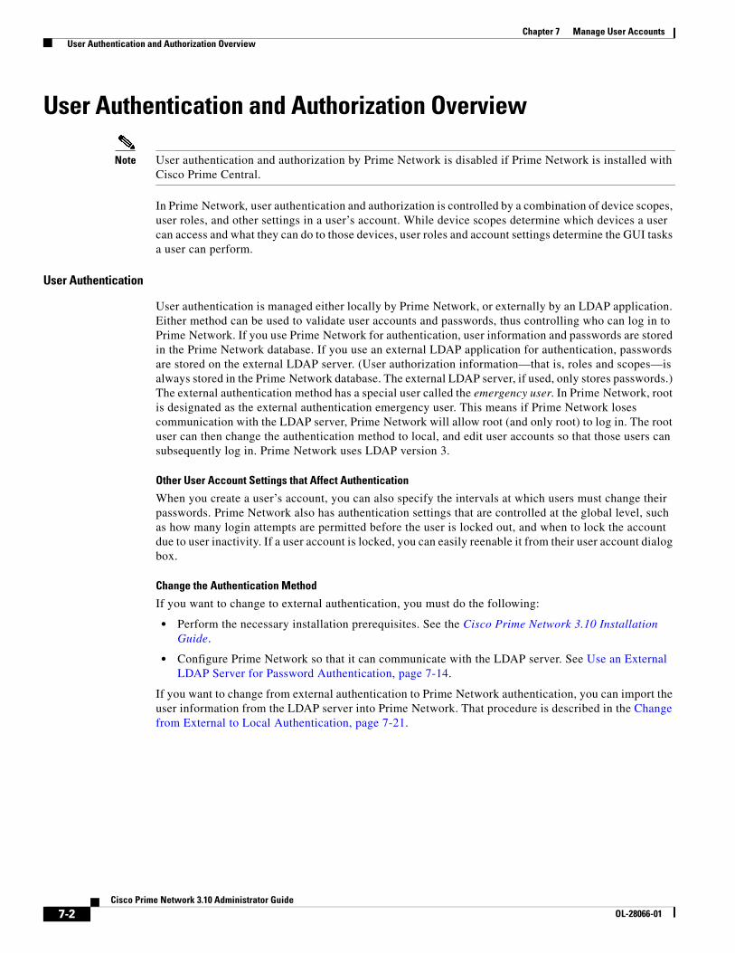
7-2Cisco Prime Network 3.10 Administrator Guide
OL-28066-01
Chapter 7 Manage User Accounts User Authentication and Authorization Overview
User Authentication and Authorization Overview
Note User authentication and authorization by Prime Network is disabled if Prime Network is installed with Cisco Prime Central.
In Prime Network, user authentication and authorization is controlled by a combination of device scopes, user roles, and other settings in a user’s account. While device scopes determine which devices a user can access and what they can do to those devices, user roles and account settings determine the GUI tasks a user can perform.
User Authentication
User authentication is managed either locally by Prime Network, or externally by an LDAP application. Either method can be used to validate user accounts and passwords, thus controlling who can log in to Prime Network. If you use Prime Network for authentication, user information and passwords are stored in the Prime Network database. If you use an external LDAP application for authentication, passwords are stored on the external LDAP server. (User authorization information—that is, roles and scopes—is always stored in the Prime Network database. The external LDAP server, if used, only stores passwords.) The external authentication method has a special user called the emergency user. In Prime Network, root is designated as the external authentication emergency user. This means if Prime Network loses communication with the LDAP server, Prime Network will allow root (and only root) to log in. The root user can then change the authentication method to local, and edit user accounts so that those users can subsequently log in. Prime Network uses LDAP version 3.
Other User Account Settings that Affect Authentication
When you create a user’s account, you can also specify the intervals at which users must change their passwords. Prime Network also has authentication settings that are controlled at the global level, such as how many login attempts are permitted before the user is locked out, and when to lock the account due to user inactivity. If a user account is locked, you can easily reenable it from their user account dialog box.
Change the Authentication Method
If you want to change to external authentication, you must do the following:
• Perform the necessary installation prerequisites. See the Cisco Prime Network 3.10 Installation Guide.
• Configure Prime Network so that it can communicate with the LDAP server. See Use an External LDAP Server for Password Authentication, page 7-14.
If you want to change from external authentication to Prime Network authentication, you can import the user information from the LDAP server into Prime Network. That procedure is described in the Change from External to Local Authentication, page 7-21.

7-3Cisco Prime Network 3.10 Administrator Guide
OL-28066-01
Chapter 7 Manage User Accounts User Authentication and Authorization Overview
User Authorization
User authorization is controlled by a combination of user roles, device scopes, and other user account settings.
User Roles
Prime Network provides five predefined security access roles that you can assign to a user when you create their account: Viewer, Operator, OperatorPlus, Configurator, and Administrator. These roles determine which actions a user is permitted to perform in the Prime Network GUI clients. Table 7-1 describes the five user roles.
Note Users with higher user roles can perform all the actions for which lower roles are authorized. For example, the Configurator is authorized to perform all the actions that the Viewer, Operator and OperatorPlus can perform.
When you create a user account, you assign one user access role to the account. This role determines the user’s default permissions, which in turn determine the GUI-based functions the user can perform (those that do not affect devices).
When a new user is defined as an Administrator, this user can perform all administrative actions, including opening all maps, working with all scopes, and managing the system using Prime Network Administration. These activities are performed with the highest privileges. Prime Network Administration supports multiple administrators.
Device Scopes
Device scopes control which devices a user can access, and the actions they can perform on those devices. When you create the user account, you assign one or more device scopes to the user’s account, along with a security level for that scope. Detailed information about device scopes and security levels is provided in Control Device Access Using Device Scopes, page 6-1. You can add device scopes to a user account Change User Accounts and Device Scope Access, page 7-12.
Other User Account Settings that Affect Authorization
When you create a user’s account, you can also specify whether the user is permitted to create public (shared) reports and manage jobs. These settings only apply if these features are enabled at the global level. In addition, you can specify that whenever any user runs a Command Builder script, Prime Network will request their credentials. These global settings are described in Configure Global
Table 7-1 User Access Roles
User Role Description
Viewer Views the network, links, events, and inventory. Has read-only access to the network and to nonprivileged system functions.
Operator Performs most day-to-day business operations such as working with existing maps, viewing network-related information, and managing business attachments.
OperatorPlus Creates new maps, and manages tickets and the alarm life cycle.
Configurator Performs tasks and tests related to configuration and activation of services, through Command Builder, Configuration Archive, NEIM, and activation commands.
Administrator Manages the Prime Network system and its security using the Prime Network Administration GUI.

7-4Cisco Prime Network 3.10 Administrator Guide
OL-28066-01
Chapter 7 Manage User Accounts Check Existing User Accounts
User Settings, page 7-5.
Check Existing User Accounts
Note This feature is disabled if Prime Network is installed with Cisco Prime Central.
To check existing user accounts, click Users in the navigation area. Figure 7-1 shows an example of the Prime Network Administration window with Users selected.
Note If Prime Network is installed with Cisco Prime Central, you can view user properties but you cannot add or change them.
Figure 7-1 Users Window
The following describes the columns that are displayed in the Users table.
Column Description
User Name The unique username defined for the current client station.
Full User Name (Optional) Full username.
Description A description of the user.
Default Permission The default permission of the user, such as Viewer or Administrator. For example, a user with the default permission Viewer can view maps and the Device List.
Note The default permission applies only at an application level; that is, it applies to all activities that are related to GUI functionality and not the activities related to devices. Device access is controlled through the device scopes mechanism.
Last Login The date and time that the user last logged in.
External Indicates whether an external authentication server is used for account and password verification.

7-5Cisco Prime Network 3.10 Administrator Guide
OL-28066-01
Chapter 7 Manage User Accounts Configure Global User Settings
Configure Global User Settings
Note This feature is disabled if Prime Network is installed with Cisco Prime Central.
Each user has an account which controls the actions they are authorized to perform and the devices they can access. The following tables list the global user account settings, their defaults, and how these global settings may interact with individual user account settings. All of these settings can be adjusted from the Administration GUI client.
The topics covered in this section are:
• User Password Settings, page 7-5
• User Permissions: Lockouts, Commands and Activations, and Job Scheduling, page 7-6
• Report Settings, page 7-8
User Password Settings
Note This feature is disabled if Prime Network is installed with Cisco Prime Central.
To change the global user password settings listed in Table 7-2, choose Global Settings > Security Settings > Password Settings. Changes are applied after you click Apply.
.
Emergency Indicates that a user is designated as an emergency user for the external authentication server, in case the external server goes down.
Jobs Authorized Indicates whether the user can schedule jobs when the per-user authorization for scheduling jobs is enabled. (See User Permissions: Lockouts, Commands and Activations, and Job Scheduling, page 7-6.
Column Description
Table 7-2 Global Password Settings
Item Description Default
Password Validity Period
Number of days after which users must reset their password. 30
Number of Attempts Before Lockout
Number of attempts before a user’s account is disabled. (Administrators can reenable accounts as described in Change User Accounts and Device Scope Access, page 7-12.)
5

7-6Cisco Prime Network 3.10 Administrator Guide
OL-28066-01
Chapter 7 Manage User Accounts Configure Global User Settings
User Permissions: Lockouts, Commands and Activations, and Job Scheduling
Note This feature is disabled if Prime Network is installed with Cisco Prime Central.
To change the global user account settings listed in Table 7-3, choose Global Settings > Security Settings > User Account Settings. Changes are applied to new users; for existing users in active sessions, the changes are applied the next time they log in.
Password Strength The last ___ passwords cannot be repeated (1 to 15) 5
Password must contain four different character types Enabled
No character can be repeated more than twice consecutively Enabled
Password cannot contain more than ___ consecutive characters from the previous passwords
4
Cannot contains replication or reversal of user name Enabled
Cannot contain the following words (comma-separated list) Cisco
Days to alert before password expires
Number of days before the password expires. User will receive a warning during the login that his password is about to expire in x days.
7
Table 7-2 Global Password Settings (continued)
Item Description Default
Table 7-3 Global User Account Settings
Item Description Default
Account Inactivity
Changes the threshold for when Prime Network should disable a user account due to inactivity. To disable the feature (so that accounts are never disabled), enter 0.
30 days

7-7Cisco Prime Network 3.10 Administrator Guide
OL-28066-01
Chapter 7 Manage User Accounts Configure Global User Settings
Execution of Commands and Activations
By default, a VNE’s Telnet credentials are used for device access when a user executes a command or activation. But if you enable this feature, users are required to enter their credentials for device access when they execute an activation or command script. Once the credentials are entered, they are used throughout the current GUI client session for all subsequent command or activation executions. The user can change the credentials using the Edit Credentials button, if necessary. Provisioning and Audit events will display an additional column that lists the device user name. If the original VNE credentials are used, they are not exposed; the device user name will display From VNE login.
For activations, users must have the same credentials for all devices involved in the activation because Prime Network propagates the credentials to all command scripts in the activation. (Scheduled commands will continue to use the VNE's credentials.)
This feature is not available for scheduled commands or activations or for SNMP commands (the user will not be prompted for credentials and the Edit Credentials button will be disabled). The VNE credentials will be used for device access.
Note You can also configure Prime Network to generate a warning message whenever a user executes a command script or an activation. Users must acknowledge the message before proceeding. See Add Warning Message to Activations and Command Scripts, page 10-6.
Disabled
Job Scheduling
Enables a per-user authorization mode for scheduling jobs.
When the mode is enabled, job scheduling privileges are controlled by the settings in individual user accounts (as described in Create a New User Account and View User Properties, page 7-9).
• If they are granted privileges, they can schedule jobs across the product.
• If they are not granted privileges, the job scheduling features in their GUI client be disabled (for example, from the Tools main menu, or when running reports or Command Builder scripts).
Disabled (all users can schedule jobs)
Table 7-3 Global User Account Settings (continued)
Item Description Default

7-8Cisco Prime Network 3.10 Administrator Guide
OL-28066-01
Chapter 7 Manage User Accounts Change GUI Client User Passwords
Report Settings
Note This feature is disabled if Prime Network is installed with Cisco Prime Central.
To change the global report setting listed in Table 7-4, choose Global Settings > Report Settings.
.
Change GUI Client User Passwords
Note This feature is disabled if Prime Network is installed with Cisco Prime Central.
When you change a user’s password using this procedure, the user must enter the new password when they log into any of the Prime Network GUI clients: Vision, Events, Administration, Workflow, and Activation Wizard Builder; and the BQL client. You can change the password for any user, including root, using the procedure in this topic.
Users must change their passwords according to the settings in their user account. At any time, users can change their password by choosing Tools > Change User Password from the any of the GUI clients.
The following procedures apply only if you are using Prime Network to validate users. If you are using an external LDAP application to manage passwords, you must change the passwords in the LDAP server.
Step 1 Select Users in the navigation pane.
Step 2 Right-click the users account, then choose Change Password.
Step 3 Enter the new password in the Password and Confirm Password fields.
Step 4 Click OK. A confirmation message is displayed.
Step 5 Click OK.
Table 7-4 Global Report Settings
Item Description Default
Security Settings
Allows all users to create shared (public) reports. When a report is public, all users can view the contents; reports are not filtered according to scopes or security privileges.
Disabled (no users can create public reports)
Purge reports after ___ days
Specifies how long to save a report. (For information on Prime Network data purging, see Reports, page 8-13.)
90 days
Store reports up to ___ MB
Specifies the maximum disk size, in MB, at which reports should be purged. (For information on Prime Network data purging, see Reports, page 8-13.)
Disabled

7-9Cisco Prime Network 3.10 Administrator Guide
OL-28066-01
Chapter 7 Manage User Accounts Create a New User Account and View User Properties
Create a New User Account and View User Properties
Note These features are disabled if Prime Network is installed with Cisco Prime Central. If a user tries to log into Prime Network, they will be redirected to the suite login page. The only exception is the Prime Network emergency user, who will still be allowed to log into standalone Prime Network. If you migrate from standalone to working with Cisco Prime Central, you must create the Cisco Prime Central users using the Cisco Prime Portal portal, even if the users already existed in standalone mode. (Cisco Prime Central will advise you that the user already existed in Prime Network and will retrieve the user properties and apply them to the new Cisco Prime Central user.)
The following procedure describes how to define a user account.
Before You Begin
Check the global security settings to see the current system defaults. You might also want to check the device scopes that are currently available.
Step 1 Right-click Users and choose New User to open the New User dialog box.
Step 2 Enter the general information about the user in the General Settings area. For existing users, click the General tab to display this information.
Field Description
User Name Enter the new user’s name to be used for logging in.
Full Name (Optional) Enter the full name of the user.
Description (Optional) Enter a free text description of the user.
External user only If checked, Prime Network will only let the user log in if the user’s password can be validated by an external LDAP server. The password fields are disabled. (If external authentication is being used, the box is checked by default. See Use an External LDAP Server for Password Authentication, page 7-14.)
Click Test Connection to confirm the connection between the gateway and the LDAP server.
Password Enter the new Prime Network password, which is then stored in the Prime Network database. Passwords must adhere to the global password rules set by the administrator (see User Password Settings, page 7-5).
This field is disabled if you are using LDAP (external user) for authentication.
Confirm Password Reenter the new Prime Network password.
7-10Cisco Prime Network 3.10 Administrator Guide
OL-28066-01
Chapter 7 Manage User Accounts Create a New User Account and View User Properties
Step 3 Click Next and configure the GUI client and device authorization settings for the user. For existing users, click the Authorization tab to display these settings.
User is authorized to schedule jobs
Gives the user authority to schedule jobs across the product if per-user job scheduling authorization mode is enabled. If the global authorization mode is disabled, this setting is ignored.
If the per-user authorization mode is enabled and:
• This checkbox is activated, the user is permitted to schedule jobs.
• This checkbox is not activated, the job scheduling features in the user’s GUI clients will be disabled.
By default, the global per-user authorization mode is disabled (all users can schedule jobs), and this setting is ignored. The per-user job scheduling authorization mode is controlled from Global Settings > Security Settings > User Account Settings.
Field Description
User Role Select the role that will control the actions the user can perform in the Prime Network, such as which functions they can use in the GUI clients. Click Read More for a description of the roles; you can also get more information from User Authentication, page 7-2. For information on the special All Managed Elements scope, see What Are Device Scopes?, page 6-1.
Device Security Select scopes and apply the security levels to them that will control the actions the user can perform on devices. You can apply different security levels for different scopes. If you do not apply a security level to a scope, it defaults to the Viewer level.
Note Users will not see any devices in the GUI client unless a device scope is assigned to their account.
Use the following buttons to manage scopes. Note that the edit and remove buttons only affect the scopes assigned to this user.
• Add—Add a scope to this user account from the list of available scopes.
• Edit—Edit the security level for a scope assigned to this user. (This edit function only changes the user’s scope security level; it does not change the scope device list. That must be done from the Scopes drawer.
• Remove—Deletes a scope from this user’s account.
• New Scope—Creates a new scope and adds it to the list of available scopes for all users. See What Are Device Scopes?, page 6-1. Changes that you apply to a scope will be applied to all users that have access to that scope.
Field Description

7-11Cisco Prime Network 3.10 Administrator Guide
OL-28066-01
Chapter 7 Manage User Accounts Create a New User Account and View User Properties
Step 4 Click Next and enter the account settings for the user. For existing users, click the Account tab to display these settings. (If you are creating a new account, you can also click Finish to accept the default account settings. The default settings are provided in the following.)
Step 5 Click Finish. and Prime Network creates the account. After the confirmation message is displayed, click Close to close the dialog box. The new account is displayed in the Users table.
Field Description Default
Enable Account Enables and disabled the user account. You can manually lock or unlock a user’s account at any time. A user whose account is locked cannot log into the system until you reenable their account.
The user account is automatically locked if:
• The number of logins defined is exceeded (see the Limit Connections field in the following).
• The user account is not active for a certain number of days, as configured in the Global Settings branch (see Unlock and Re-enable User Accounts, page 7-23); by default, this period is 30 days.
Enabled.
Force Password Change at Next Login
Check this check box to force the user to change their user password when they next log in. This field is disabled if the gateway server is using external LDAP authentication.
Enabled.
Limit Connections: Maximum number of Prime Network client sessions that a user can be running at any one time (to protect performance). This BQL sessions and workflow invocations. Leaving this field blank means the user can have unlimited connections.
Note The workflow mechanism requires 3 connections. If you set this value to lower than 3, users will not be able to access the workflow mechanism.
10 connections
Force Password Change After ___ Days
Forces the user to change their password after a specific number of days. Uncheck this check box to allow the user to retain their current password indefinitely.
This field is disabled if the gateway server is using external LDAP authentication.
Controlled by Global Settings; see User Password Settings, page 7-5.

7-12Cisco Prime Network 3.10 Administrator Guide
OL-28066-01
Chapter 7 Manage User Accounts Create a New User Account and View User Properties
Change User Accounts and Device Scope Access
Note These features are disabled if Prime Network is installed with Cisco Prime Central.
Administrators can view, edit, or disable an individual user’s account settings. To change global settings such as password rules and inactivity periods, see System Security, page 11-1.
Step 1 Select Users to populate the list of existing user accounts.
Step 2 Right-click a user account and choose Properties to open the user properties dialog box.
Step 3 Edit the following fields, as required (not all fields are editable).
Step 4 Click Apply to apply your changes, and click OK to close the Properties dialog box
Field Description
General Tab
User Name User ID of the user logged in to the system.
Full Name (Optional) Full name of the user.
Description (Optional) Free text description of the user.
External User only Select this option if the user is an external user.
User is authorized to schedule jobs
Select this option if the user can schedule jobs.
Authorization Tab
User Role The role that will control the actions the user can perform in the Prime Network, such as which functions they can use in the GUI clients. For information on how to make changes, see Configure Global User Settings, page 7-5.
Device Security Scopes and apply the security levels to them that will control the actions the user can perform on devices. For information on how to make changes, see Configure Global User Settings, page 7-5.
Account Tab
Enable Account Enables and disabled the user account.
Force Password Change at Next Login
Force the user to change their user password when they next log in. This field is disabled if the gateway server is using external LDAP authentication.
Limit Connections: The maximum number of Prime Network client sessions that the user can be running at any one time. This includes all client types.
Force Password Change After ___ Days
Forces the user to change their password after a specific number of days. Uncheck this check box to allow the user to retain their current password indefinitely.
This field is disabled if the gateway server is using external LDAP authentication.
User Last Login Displays date and time of the last login.
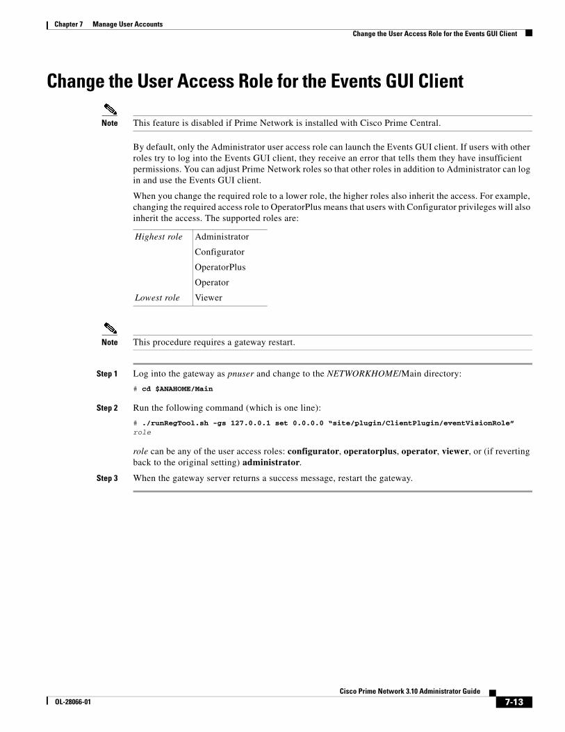
7-13Cisco Prime Network 3.10 Administrator Guide
OL-28066-01
Chapter 7 Manage User Accounts Change the User Access Role for the Events GUI Client
Change the User Access Role for the Events GUI Client
Note This feature is disabled if Prime Network is installed with Cisco Prime Central.
By default, only the Administrator user access role can launch the Events GUI client. If users with other roles try to log into the Events GUI client, they receive an error that tells them they have insufficient permissions. You can adjust Prime Network roles so that other roles in addition to Administrator can log in and use the Events GUI client.
When you change the required role to a lower role, the higher roles also inherit the access. For example, changing the required access role to OperatorPlus means that users with Configurator privileges will also inherit the access. The supported roles are:
Note This procedure requires a gateway restart.
Step 1 Log into the gateway as pnuser and change to the NETWORKHOME/Main directory:
# cd $ANAHOME/Main
Step 2 Run the following command (which is one line):
# ./runRegTool.sh -gs 127.0.0.1 set 0.0.0.0 “site/plugin/ClientPlugin/eventVisionRole” role
role can be any of the user access roles: configurator, operatorplus, operator, viewer, or (if reverting back to the original setting) administrator.
Step 3 When the gateway server returns a success message, restart the gateway.
Highest role Administrator
Configurator
OperatorPlus
Operator
Lowest role Viewer
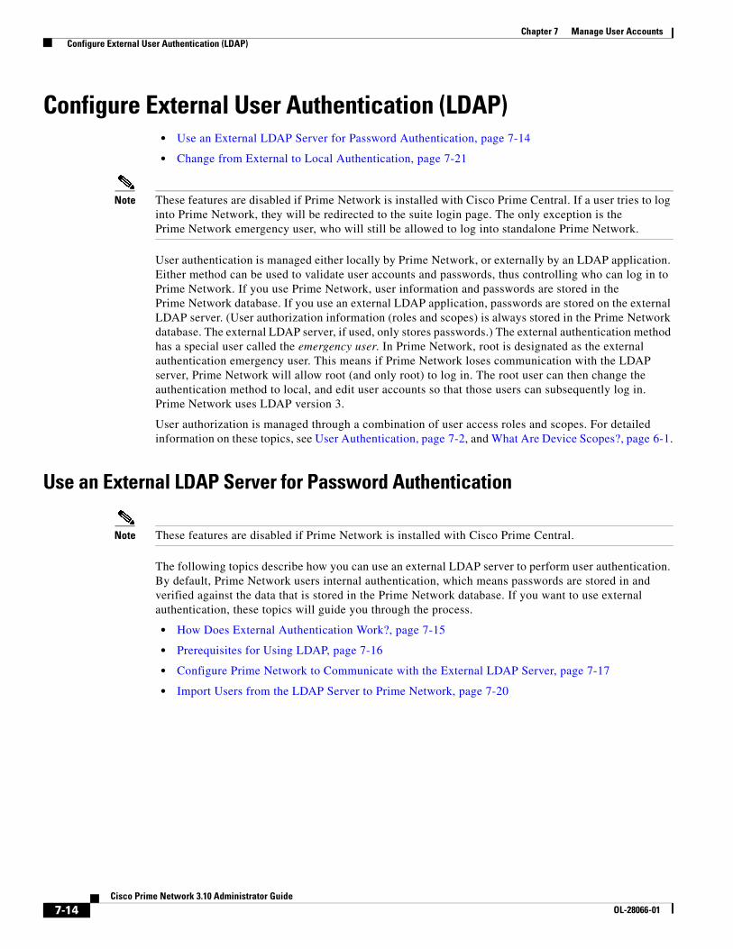
7-14Cisco Prime Network 3.10 Administrator Guide
OL-28066-01
Chapter 7 Manage User Accounts Configure External User Authentication (LDAP)
Configure External User Authentication (LDAP) • Use an External LDAP Server for Password Authentication, page 7-14
• Change from External to Local Authentication, page 7-21
Note These features are disabled if Prime Network is installed with Cisco Prime Central. If a user tries to log into Prime Network, they will be redirected to the suite login page. The only exception is the Prime Network emergency user, who will still be allowed to log into standalone Prime Network.
User authentication is managed either locally by Prime Network, or externally by an LDAP application. Either method can be used to validate user accounts and passwords, thus controlling who can log in to Prime Network. If you use Prime Network, user information and passwords are stored in the Prime Network database. If you use an external LDAP application, passwords are stored on the external LDAP server. (User authorization information (roles and scopes) is always stored in the Prime Network database. The external LDAP server, if used, only stores passwords.) The external authentication method has a special user called the emergency user. In Prime Network, root is designated as the external authentication emergency user. This means if Prime Network loses communication with the LDAP server, Prime Network will allow root (and only root) to log in. The root user can then change the authentication method to local, and edit user accounts so that those users can subsequently log in. Prime Network uses LDAP version 3.
User authorization is managed through a combination of user access roles and scopes. For detailed information on these topics, see User Authentication, page 7-2, and What Are Device Scopes?, page 6-1.
Use an External LDAP Server for Password Authentication
Note These features are disabled if Prime Network is installed with Cisco Prime Central.
The following topics describe how you can use an external LDAP server to perform user authentication. By default, Prime Network users internal authentication, which means passwords are stored in and verified against the data that is stored in the Prime Network database. If you want to use external authentication, these topics will guide you through the process.
• How Does External Authentication Work?, page 7-15
• Prerequisites for Using LDAP, page 7-16
• Configure Prime Network to Communicate with the External LDAP Server, page 7-17
• Import Users from the LDAP Server to Prime Network, page 7-20

7-15Cisco Prime Network 3.10 Administrator Guide
OL-28066-01
Chapter 7 Manage User Accounts Configure External User Authentication (LDAP)
How Does External Authentication Work?
Note These features are disabled if Prime Network is installed with Cisco Prime Central.
User authentication can be managed locally by Prime Network or externally by a Lightweight Directory Access Protocol (LDAP) application. If you use an external authentication, user information is checked against what is stored in the external LDAP server (instead of the Prime Network database). The external authentication server only stores login and password information; information pertaining to user roles and scopes is stored in the Prime Network database.
As illustrated in Figure 7-2, when a user logs in to the GUI client, the gateway server contacts the LDAP server to authenticate the user. If the user is successfully authenticated, the LDAP server sends a confirmation to the gateway server, and the gateway server allows the user to log in to Prime Network. From that point on, the user can perform functions and access network elements as specified by their roles and scopes (see Change a User’s Device Scope Security Level, page 6-5).
Figure 7-2 User Authentication Process with External LDAP Server
The root user is the emergency user. The LDAP emergency user is validated only by Prime Network. Consequently, if the LDAP server goes down, root can log back into Prime Network.
Note If Prime Network is installed with Cisco Prime Central, the emergency user will still be allowed to log into Prime Network.
LDAPAuthentication
ServerPrime Network
Gateway Server
Prime NetworkGUI Client
2842
40
User attempts to login to Prime Network
GUI client.
Prime Network gateway verifiesthat user account exists and is enabled,and connects to LDAP server. (If the user account does not exist or isdisabled, Prime Network denies the login.)
LDAP server validatesthe user and sendsconfirmation toPrime Networkgateway server.
Prime Networkgateway server allowsuser to log in to GUI client.
1 4
2
3

7-16Cisco Prime Network 3.10 Administrator Guide
OL-28066-01
Chapter 7 Manage User Accounts Configure External User Authentication (LDAP)
Prerequisites for Using LDAP
Note These features are disabled if Prime Network is installed with Cisco Prime Central.
You must meet the following prerequisites before you can configure Prime Network to use LDAP:
• The LDAP server must be reachable from the Prime Network server, including port 389 for nonencrypted communication, 636 for encrypted communication.
• The LDAP server must support LDAPv3 protocol.
• Windows Server 2003 Active Directory must be configured. Configure a Secure Connection with the Windows Server 2003 Active Directory, page 7-16
• For encrypted communication, a certificate must be installed on the Prime Network server. See Install the LDAP Certificate on the Prime Network Gateway Server, page 7-17.
Configure a Secure Connection with the Windows Server 2003 Active Directory
To manage users in the Active Directory from Java, the connection to the server must be secure. Follow these procedures to make the server connection secure.
If you are using Secure Socket Layer (SSL) for encryption between the Prime Network server and the LDAP server, the Windows server must be a domain controller installed with an Enterprise Certificate Authority. To guarantee a secure connection, you must request and install the appropriate certificate.
Note This procedure requires a gateway restart.
To obtain the certificate from the LDAP server and place it on the gateway:
Step 1 Use Router Discovery Protocol (RDP) to log into the remote LDAP server.
Step 2 Choose Start > Programs > Administrative Tools > Domain Controller Security Policy.
Step 3 In the left pane, choose Security Settings > Public Key Policies > Automatic Certificate Request Settings.
Step 4 Right-click the right pane and choose New > Automatic Certificate Request.
Step 5 Click Next.
Step 6 Choose Domain Controller and click Next.
Step 7 Click Finish.
Step 8 Restart the server.
Step 9 After the server restarts, enter the following command on the command line:
# netstat -na
The SSL port 636 should be active; for example:
TCP 0.0.0.0:636 0.0.0.0:0 LISTENING

7-17Cisco Prime Network 3.10 Administrator Guide
OL-28066-01
Chapter 7 Manage User Accounts Configure External User Authentication (LDAP)
Install the LDAP Certificate on the Prime Network Gateway Server
Prime Network requires a certificate to open a context with the LDAP server. To import the certificate into the system .truststore file, complete the following steps:
Step 1 Download the certificate from the relevant LDAP workstation:
a. From the client workstation, go to http://ldaphost/certsrv, where ldaphost is the fully qualified domain name or IP address of the LDAP server.
b. For blade LDAP, enter the service provider username and password.
c. Click Download a CA certificate, certificate chain, or CRL.
d. Choose Previous cmpdc in the CA certificate option.
e. Click Download CA certificate.
f. Save the certnew.cer file on the workstation. You can rename the file as CA.LDAP-IP-address.cer.
Step 2 Log into your workstation.
Step 3 Go to ~/Main/resourcebundle/com/sheer and copy the .cer file to that directory.
Step 4 Enter the following command on the command line:
# keytool -import -alias LDAPID -file CA.LDAP-IP-address.cer -keystore .truststore
Note Use the password in the security.properties file in this directory. Be sure to use a unique ID to set a unique alias.
Step 5 Enter the following command to check your LDAP certificates on the system .truststore file:
# keytool -list -keystore .truststore
Configure Prime Network to Communicate with the External LDAP Server
Note These features are disabled if Prime Network is installed with Cisco Prime Central.
Use this procedure to configure the Prime Network gateway server to communicate with the LDAP server, and to test the connection after it is configured. You can configure a primary and secondary LDAP server. This procedure uses LDAP terminology, such as distinguished name (DN), common name (CN), and domain component (DC). An LDAP distinguished name uniquely identifies a user in the LDAP database, similar to a full filename but in reverse order. CNs and DCs are attributes of the domain name.
Before You Begin
Make sure you have performed the required prerequisites that are described in the Cisco Prime Network 3.10 Installation Guide:
• The LDAP server is correctly configured.
• You know the port number needed for the SSL or simple encryption protocol. These are normally 636 for SSL and 389 for simple.

7-18Cisco Prime Network 3.10 Administrator Guide
OL-28066-01
Chapter 7 Manage User Accounts Configure External User Authentication (LDAP)
• If you select SSL for the Application-LDAP Protocol, the SSL certificate must be installed on the Prime Network gateway.
You must have Administrator privileges (user access role) to use this and all other functions in Prime Network Administration.
Note This procedure requires a gateway restart.
To configure the Prime Network gateway server to communicate with the LDAP server:
Step 1 Choose Global Settings > Security > Authentication Method. Figure 7-3 provides an example of the Authentication Method window.
Figure 7-3 Authentication Method Window
Step 2 Click LDAP Authentication to activate the LDAP Settings area.

7-19Cisco Prime Network 3.10 Administrator Guide
OL-28066-01
Chapter 7 Manage User Accounts Configure External User Authentication (LDAP)
Step 3 Complete the LDAP settings. The settings include specifying LDAP schema attributes, such as CN (common name) and DC (domain component).
Table 7-5 LDAP Authentication Method Settings
Field Description
LDAP URL LDAP server name and port number, in the following format:
ldap://host.company.com:port
where:
• host.company.com—Fully qualified domain name or IP address of the LDAP server, followed by the final two fields of the Distinguished Name Suffix (company.com, described below
• port—Network port of the LDAP server. The LDAP server port number is normally 389 for simple encryption and 636 for SSL encryption.
To specify a primary and secondary LDAP server, use the following format:
ldap://host1.company.com:port1 ldap://host2.company.com:port2
For example:
ldap://ldapsj.acme.com:636 ldap://ldapsfo.acme.com:636
Distinguished Name Prefix
First part of the LDAP DN, which is used to uniquely identify users. Enter the information exactly as shown:
CN
(The actual format is CN=Value, which specifies the common name for specific users. =Value will be automatically populated with Prime Network usernames.)
Distinguished Name Suffix
Second part of the LDAP distinguished name, which specifies the location in the directory:
,CN=Users,DC=LDAP_server,DC=company,DC=com
where:
• ,CN=Users—Common name for the type of user; enter Users. For example:
,DC=Users
• ,DC=LDAP_server—Domain component that specifies the fully qualified domain name or IP address of the Prime Network server. For example:
,DC=ldapsj
• ,DC=company—Beginning of the domain name. For example:
,DC=acme
• ,DC=com—End of the domain name; enter com. For example:
,DC=com
The form should:
• Begin with a comma.
• End without any ending symbols or punctuation.
For example:
,CN=Users,DC=ldapsj,DC=cisco,DC=com

7-20Cisco Prime Network 3.10 Administrator Guide
OL-28066-01
Chapter 7 Manage User Accounts Configure External User Authentication (LDAP)
Step 4 Click Test Connection to test the connection between the gateway server and the LDAP server.
Step 5 Click Apply.
Step 6 Restart the gateway for your changes to take effect. See Stop and Restart Prime Network Components, page 3-15.
You can now manage user passwords using the external LDAP server.
Import Users from the LDAP Server to Prime Network
Note These features are disabled if Prime Network is installed with Cisco Prime Central.
To import users from an LDAP server into Prime Network, you must first create and LDAP Data Interchange Format (LDIF) file using the ldifde command, and then import the file into Prime Network using the import_users_from_LDIF_file.pl command.
This command produces an LDIF file for a Windows LDAP server:
# ldifde -l description,displayName,userPrincipalName -f desired-filename -r objectClass=user
The following shows sample contents of an LDIF file named users.LDF:
dn: CN=xxx,CN=Users,DC=ldapsj,DC=comchangetype: adddisplayName: xxxuserPrincipalName: [email protected]
dn: CN=yyyy,CN=Users,DC=ldapsj,DC=comchangetype: adddisplayName: yyyyuserPrincipalName: [email protected]
dn: CN=zzz,CN=Users,DC=ldapsj,DC=comchangetype: adddescription: descriptiondisplayName: zzzuserPrincipalName: [email protected]
Application-LDAP Protocol
Encryption protocol used for communication between the Prime Network gateway server and the LDAP server.
Note The encryption protocol used must be configured on both the Prime Network gateway server and the LDAP server.
The supported protocols are:
• SIMPLE—Encrypt using LDAP. Uses port 389 by default.
• SSL—Encrypt using SSL. Uses port 636 by default. The SSL certificate must be installed on the Prime Network gateway (see the Cisco Prime Network 3.10 Installation Guide).
Table 7-5 LDAP Authentication Method Settings (continued)
Field Description

7-21Cisco Prime Network 3.10 Administrator Guide
OL-28066-01
Chapter 7 Manage User Accounts Configure External User Authentication (LDAP)
The import_users_from_LDIF_file.pl command has the following syntax:
import_users_from_LDIF_file.pl ldif-filename [roleName] username-attribute-name [user-desc-attribute-name] [full-name-attribute-name]
Where:
The following command imports the LDAP users listed in the users.LDF file into Prime Network. It creates three users with a Viewer role.
# cd $ANAHOME/Main/scripts# import_users_from_LDIF_file.pl users.LDF userPrincipalName description displayName
Note All imported users are created with non-Prime Network authentication permissions (LDAP authentication). If the username already exists in Prime Network, the new user is not created.
Change from External to Local Authentication
Note The Authentication Method feature is disabled if Prime Network is installed with Cisco Prime Central. However, the emergency user will still be allowed to log into Prime Network.
If Prime Network is using external authentication and cannot communicate with the LDAP server, the only user permitted to log back into Prime Network is root. This is because root is the emergency user, and is validated only by Prime Network. The root user can then log into Prime Network, change the authentication method to local, and edit user accounts so that those users can subsequently log in. For information on editing user accounts, see Change User Accounts and Device Scope Access, page 7-12.
You must have Administrator privileges (user access role) to use this and all other functions in Prime Network Administration.
Note This procedure requires a gateway restart.
Argument Description
ldif-filename LDIF file name. It should reside in NETWORKHOME/Main.
roleName Prime Network user role: Administrator, Configurator, Operator, OperatorPlus, and Viewer (default=Viewer)
username-attribute-name Attribute name as it appears in the LDIF file. The username can appear in the LDIF file as username only, or in the format username@domain. In both cases, after the import, the Prime Network user is the name only (without the @domain suffix).
Mandatory for each user.
user-desc-attribute-name Attribute name as it appears in the LDIF file. Optional for each user.
full-name-attribute-name Attribute name as it appears in the LDIF file. Optional for each user.

7-22Cisco Prime Network 3.10 Administrator Guide
OL-28066-01
Chapter 7 Manage User Accounts Control User Access to Maps
To change from external to local authentication, follow this procedure:
Step 1 Choose Global Settings > Security > Authentication Method.
Step 2 Click Prime Network Authentication to activate local authentication.
Step 3 Click Apply.
Step 4 Restart the gateway for your changes to take effect. See Stop and Restart Prime Network Components, page 3-15.
Step 5 Reconfigure user accounts accordingly (see Change User Accounts and Device Scope Access, page 7-12).
Control User Access to Maps
Note These features are disabled if Prime Network is installed with Cisco Prime Central.
You can use the Maps tab to control user access to existing maps. This feature is disabled by default. You must first enable it and then you can control map access.
When logging into Prime Network Vision, new users do not have permission to view any existing maps; they can only access maps they create going forward. However, administrators can assign existing maps to new users by enabling this feature and manually assigning the maps.
You must have Administrator privileges (user access role) to use this and all other functions in Prime Network Administration.
Note These procedures requires a gateway restart.
To enable this feature:
Step 1 Log into the gateway as pnuser and change to the NETWORKHOME/Main directory:
# cd $ANAHOME/Main
Step 2 Run the following command (which is one line):
# ./runRegTool.sh -gs 127.0.0.1 set 0.0.0.0 “site/mmvm/services/securitymanager/map-security-enabled” true
Step 3 When the gateway server returns a success message, restart the gateway.
To assign maps to a user (after enabling the feature):
Step 1 Select Users in the Prime Network window.
Step 2 Right-click the required user, then choose Properties. The User Properties dialog box is displayed.

7-23Cisco Prime Network 3.10 Administrator Guide
OL-28066-01
Chapter 7 Manage User Accounts Unlock and Re-enable User Accounts
Step 3 Click the Maps tab. The Maps tab is divided into two parts:
• The left side displays a list of all available maps in the database that have not been assigned to the user.
• The right side displays all maps that have been assigned to the user and that the user can open and manage in Prime Network Vision.
Step 4 Choose a map from the list of Available Maps, then click the required button to add the map to the list of Assigned Maps to the user.
Step 5 Choose and move maps between the two lists, as required, using the appropriate buttons.
Step 6 Click OK to confirm the user’s assigned maps.
Unlock and Re-enable User Accounts
Note This feature is disabled if Prime Network is installed with Cisco Prime Central.
User accounts can become locked or disabled for two reasons:
• A user entered the wrong password, exceeding the number of permitted retries. The retries setting is controlled from the Password Settings window.
• The user has not logged in, exceeding the account inactivity period.
The settings that control these actions are specified in the Global Settings; see User Permissions: Lockouts, Commands and Activations, and Job Scheduling, page 7-6.
To reenable a locked account:
Step 1 Select Users to populate the list of existing user accounts.
Step 2 Right-click a user account and choose Properties to open the user properties dialog box.
Step 3 In the Account tab, check the Enable Account check box.
Step 4 Save your changes.

7-24Cisco Prime Network 3.10 Administrator Guide
OL-28066-01
Chapter 7 Manage User Accounts Delete a Prime Network User Account
Delete a Prime Network User Account
Note This feature is disabled if Prime Network is installed with Cisco Prime Central.
If you want to disable a user account but not delete it, see Change User Accounts and Device Scope Access, page 7-12.
To delete a user account:
Step 1 Select Users in the navigation pane.
Step 2 Right-click the account you want to remove, then choose Delete.
The account is deleted and is removed from the content area.
Track User-Related EventsThe following table provides ways you can get historical information on user-related events. You can tailor your search or reports by specifying keywords (such as user).
Information Type Refer to:
Recent Security events Security tab in Event GUI client
Historical data on Security events for a specific time period and/or specific events
From the main menu, choose Reports > Run Report > Events Reports > Detailed Non-Network Events > Security Events

C H A P T E R
8-1Cisco Prime Network 3.10 Administrator Guide
OL-28066-01
8Manage the Database and System Data
These topics explain how to manage the data that is used by Prime Network, including how to change how often data is archived and purged, how Prime Network organizes data in the database (embedded or external), and how to keep the system stable.
• Overview of the Prime Network Database and Schemas, page 8-1
• Control How Data is Saved, Archived, and Purged, page 8-4
• Manage an Embedded Database, page 8-15
• Prevent System Overloads (Advanced Overload Prevention/Safe Mode), page 8-23
• Track Database and System Integrity Events, page 8-26
To change database passwords, see Change Password for Database Schemas, page 11-9.
For more information on the Event Archive and Fault Database and the flow of events through Prime Network, see Control Event Monitoring, page 9-1.
Overview of the Prime Network Database and SchemasPrime Network supports two types of database installations:
Both types of databases can be installed on the gateway server or on a separate server.
Database Schemas
A Prime Network application operating system account is created when Prime Network is installed. When Prime Network creates the database schemas, it uses this operating system account name as the default for naming the schemas.
Type of DB Description Is the DB backed up with Prime Network?
Embedded database
The Oracle database is fully integrated with Prime Network. You can use native tools to manage and monitor your database
Yes. An embedded database is backed up depending on the database profile selected during gateway installation. For more information, see Back Up and Restore Process, page 2-9.
External database
The database is managed separately from Prime Network using the tools provided by Oracle.
No. Only Prime Network registry and other data stored on the gateway is backed up. You must back up the database using the Oracle tools.

8-2Cisco Prime Network 3.10 Administrator Guide
OL-28066-01
Chapter 8 Manage the Database and System Data Overview of the Prime Network Database and Schemas
Table 8-1 lists the database schemas that are created by Prime Network. It also provides examples of what the schema names would be if pnuser (the operating system account for the Prime Network application) was defined as pn310 at installation time. You can also create the schemas manually, using different names, as described in the Cisco Prime Network 3.10 Installation Guide, but the purpose of each schema remains the same.
Table 8-1 Prime Network Database Schemas
Default Schema Names Description
Example Schema Name
pnuser Prime Network main schema that contains most Prime Network data. This schema also contains the Fault Database (the tables that are related to the fault application):
• Network fault and event tables—NETWORKEVENT, ALARM, and TICKET tables. Each of these tables contain an active partition and time-based archive partitions. Tickets can be manually or automatically archived. When data is archived, it is moved to an archive partition based on the object timestamp. Archive partitions which exceeds the history size (14 days by default) are deleted.
• Non-network fault and event tables—SYSTEMEVENT, AUDITEVENT, SECURITYEVENT, PROVISIONINGEVENT, NEWTRAPEVENT, NEWTRAPVALUE, MONITOR. Each of these tables contain only time-based archive partitions. Archive partitions which exceed the history size (14 days by default), are deleted.
To change the settings that control when events are purged from the Fault Database, see Events, Alarms, and Tickets, page 8-8. A special process also purges tickets when the number of tickets exceeds its threshold; see Manage an Embedded Database, page 8-15.
pn310
pnuser_ep Prime Network Event Archive (event persistence) schema that contains the following tables:
• HP_SYSLOG
• HP_TRAP
The pnuser_ep schema contains all raw events that are sent from devices to Prime Network. Specifically, these raw events are received by the Event Collector (on AVM 100) and persisted in the Event Archive. The data is arranged in time-based partitions. When a partition’s age exceeds its history size (14 days by default), the data is deleted. You can disable event archiving using the procedure in Disable Saving Raw Events to the Event Archive, page 8-12.
To change the settings that control when events are purged from the Event Archive, see Events, Alarms, and Tickets, page 8-8.
pn310_ep
pnuser_rep Prime Network reports schema that contains synonyms based on the pnuser schema tables; it is used by the reports mechanism. Reports are deleted according to the workflowEngine integrity test; see Reports, page 8-13.
pn310_rep
pnuser_ep_rep Prime Network reports schema that contains synonyms based on the pnuser_ep schema tables; it used by the reports mechanism. Reports are deleted according to the workflowEngine integrity test; see Reports, page 8-13.
pn310_ep_rep

8-3Cisco Prime Network 3.10 Administrator Guide
OL-28066-01
Chapter 8 Manage the Database and System Data Overview of the Prime Network Database and Schemas
Table 8-2 lists the main tables used by the pnuser schema. They are listed here to aid in troubleshooting purposes (for example, if you see any missing statistics messages in the AVM 11 log (NETWORK_HOME/logs/11.out), they could be referring to tables that are no longer used by Prime Network).
pnuser_dwe Prime Network Workflow Engine schema that contains all data (templates and workflows) related to the Workflow Engine. The Workflow Engine is described in Manage Workflows, Command Scripts, and Activations, page 10-1.
Workflows are deleted according to the workflowEngine integrity test; see Table 8-4 on page 8-7.
pn310_dwe
pnuser_xmp Prime Network Change and Configuration Management schema that contains all data related to the functions of Change and Configuration Management. This feature is optionally installed with Prime Network and is described in the Cisco Prime Network 3.10 Installation Guide. For more information on Change and Configuration Management, see the Cisco Prime Network 3.10 User Guide.
pn310_xmp
pnuser_admin User with database administrator permissions who can run maintenance tasks—such as gathering statistics—on the other Prime Network database schemas. If this user is created with the proper permissions (as described in the installation guide), Prime Network will run a cron job called every_24_hours.cmd that gathers statistics on other database tables. This provides an automatic method for generating database statistics, which is recommended for better performance. For more information, see the Cisco Prime Network 3.10 Installation Guide.
pn310_admin
Table 8-1 Prime Network Database Schemas (continued)
Default Schema Names Description
Example Schema Name
Table 8-2 Database Tables in the pnuser Schema
Primary Tables (Tables with More Traffic)
ALARM
AUDITEVENT
NETWORKEVENT
NEWAFFECTEDSNC
NEWTRAPEVENT
NEWTRAPVALUE
NOTIFICATION
PROVISIONINGEVENT
SECURITYEVENT
SEVERITYASPECT
SYSTEMEVENT
TICKET

8-4Cisco Prime Network 3.10 Administrator Guide
OL-28066-01
Chapter 8 Manage the Database and System Data Control How Data is Saved, Archived, and Purged
Control How Data is Saved, Archived, and PurgedThe Prime Network defaults for saving and deleting data ensure that current data remains available, while not impacting system performance. Table 8-3 lists the defaults for removing data from the system. You can adjust these settings according to the needs of your deployment. These mechanisms are described in the following topics:
• What is the Difference Between Clearing, Archiving, and Purging Fault Data?, page 8-5
• How the Data Purging Mechanism Works, page 8-6
• Events, Alarms, and Tickets, page 8-8
• Configuration Archives and Software Images, page 8-13
• Jobs, page 8-13
• Reports, page 8-13
• Diagnostic Data (Graphs Tool), page 8-15
• Workflows and Activations, page 8-14
Table 8-3 lists the default settings for deleting data from Prime Network.
Tables with Less Traffic
BOSRESULTS
BOSUSER
BUSINESSOBJECT
CLIENTREGISTRY
CONNECTIONTP
CUSTOMER
EFPCROSSCONNECT
ETHERNETFLOWDOMAIN
ETHERNETSERVICE
ETHFLOWPOINT
EVC
HIERARCHYNODE
LCA
MAP
MAPASPECT
MAPDATAASPECT
MARTINITUNNELPEER
NETWORKPSEUDOWIRE
NETWORKVLAN
NOTE
OIDARRAYS
PASSWORDHISTORYENTRY
PERMISSION
PSEUDOWIREEDGE
PWSWITCHINGENTITY
RECONCILIATIONASPECT
REPORT
REPORTDATA
SCOPE
SERVICE
SITE
SWITCHINGENTITY
VIRTUALROUTER
VLANPERSISTEDLINK
VPLSFORWARD
VPLSINSTANCE
VPN
Table 8-2 Database Tables in the pnuser Schema (continued)
Primary Tables (Tables with More Traffic)
Table 8-3 Default Settings for Purging Data
Data Purged After (Default):
Database—Fault Database1 14 days
Database—Event Archive 14 days
Jobs Never purged

8-5Cisco Prime Network 3.10 Administrator Guide
OL-28066-01
Chapter 8 Manage the Database and System Data Control How Data is Saved, Archived, and Purged
What is the Difference Between Clearing, Archiving, and Purging Fault Data?Table 8-3 lists the default settings for when data is purged (deleted) from Prime Network, either from the database, or from gateway file systems. Fault data—that is, the data saved in the Fault Database—has a more complex purging mechanism that also involves clearing and archiving.
Note In some cases a distinction is drawn between network events and non-network events. Network events are Service, Trap, and Syslog events. Non-network events are System, Security, and Provisioning events.
Clearing
A cleared ticket means the event, alarm, or ticket should no longer be considered a problem. Users can manually clear (force clear) an item from the Vision or Events GUI clients, or by using BQL. When an item is cleared, its severity icon changes to a green check mark, providing a visual indication that the problem has been addressed. (Acknowledging an event is different. Acknowledging indicates that someone is aware of the issue. Acknowledging does not change the severity icon; it just changes its Acknowledged value to True.)
To maintain system stability, tickets that are very large (have 150 associated events) are automatically cleared so that system performance is not degraded. This is done by default.
You can configure Prime Network to automatically clear tickets based on a certain severity or age. This feature is not enabled by default. To set this auto-clear mechanism, see Change Fault Settings: Clear, Archive, and Purge Fault Data, page 8-8.
Archiving
Archived data is data that is moved to an archive partition in the Fault Database. When fault information is first saved, it is saved in the active partition of a database event table. Database event tables also have archive partitions, which are further divided into time-based subpartitions. When an event or ticket is
Reports 90 days
Prime Network backups for systems with external database
5 backups
Prime Network backups for systems with embedded database2
16 backups
Executed activations 7 days
Executed workflows 7 days
Diagnostics (Graphs) tool 29 days
Configuration Archive files and change logs 30 days
Software Images n/a (manual deletions only)
1. Tickets are deleted 14 days after they are moved to an archive partition. Events in an archive partition are deleted 14 after they are received by the system. For more information, see What is the Difference Between Clearing, Archiving, and Purging Fault Data?, page 8-5.
2. See Manage an Embedded Database, page 8-15 for information on additional checks that are performed by Prime Network.
Table 8-3 Default Settings for Purging Data
Data Purged After (Default):

8-6Cisco Prime Network 3.10 Administrator Guide
OL-28066-01
Chapter 8 Manage the Database and System Data Control How Data is Saved, Archived, and Purged
archived, it is moved from the active partition to the archive partition. When it is moved to the archive partition, the event or ticket begins aging, based on its detection time. It is deleted after 14 days, by default.
Note Archiving network events, tickets, and alarms is not the same as saving data in the Event Archive. The Event Archive is the database area where raw events are saved; it is completely different from the archive and active partitions that contain fault data.
Only tickets, alarms, and network events (Service, Trap, and Syslog events) are archived. When a ticket is archived, all of the events and alarms associated with the ticket are also archived.
Automatic archiving is done to protect system performance. A ticket is automatically archived if it meets any of the following conditions:
• The ticket contains an alarm that has more than 150 events associated with it
• The ticket has been in a cleared, unchanged state for 1 hour
• The ticket exceeds the configured ticket threshold (16,000 by default)
You can also manually archive and event, alarm, or ticket from the GUI client or by using BQL.
Purging
When an event (or any other data) is purged from Prime Network, it is permanently removed from the database or other storage directories. This data can only be retrieved if it has been saved to an external location. Most data is purged after 14 days, but this depends on its type of data. For more information, see How the Data Purging Mechanism Works, page 8-6.
How the Data Purging Mechanism WorksPrime Network maintains system stability by running cron jobs to maintain the database and eliminate clutter in the system, especially fault management data. Some jobs are run every 12 hours, while others are run every hour.
Different cron jobs are run on different schedules. To check the current schedules, use this procedure.
Step 1 Using an SSH session, log into the Prime Network gateway as pnuser. (pnuser is the operating system account for the Prime Network application, created when Prime Network is installed; for example, pn310.)
Step 2 Use the following command to list the contents of the crontab file for user pnuser. The local/cron directories listed below are all located in NETWORKHOME.
# crontab -l# Cisco Prime Network crontab file# contains scheduled tasks for user prime-network* * * * * if [ -f local/cron/every_1_minute.cmd ]; then local/cron/every_1_minute.cmd > /dev/null 2>&1; fi* * * * * /var/adm/cisco/prime-network/scripts/keep_alive_port_watchdog.pl > /dev/null 2>&10 * * * * if [ -f local/cron/every_1_hour.cmd ]; then local/cron/every_1_hour.cmd > /dev/null 2>&1; fi0 4,16 * * * if [ -f local/cron/every_12_hours.cmd ]; then local/cron/every_12_hours.cmd > /dev/null 2>&1; fi0 23 * * * if [ -f local/cron/every_24_hours.cmd ]; then local/cron/every_24_hours.cmd > /dev/null 2>&1; fi
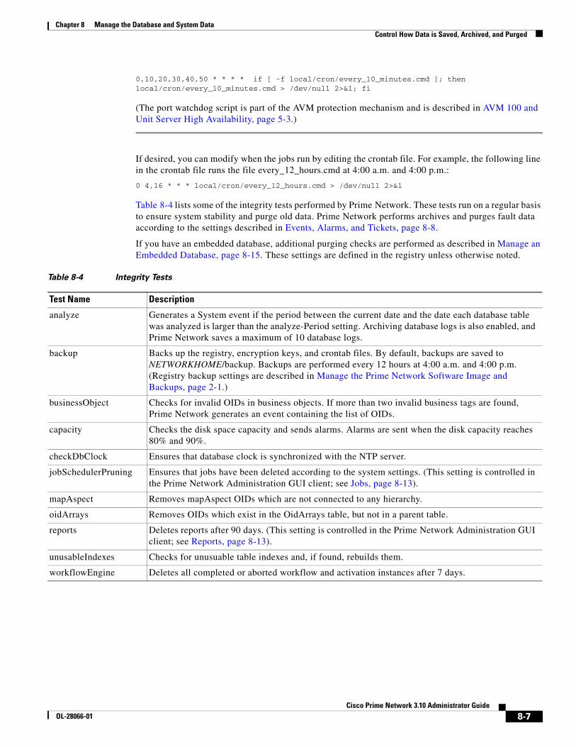
8-7Cisco Prime Network 3.10 Administrator Guide
OL-28066-01
Chapter 8 Manage the Database and System Data Control How Data is Saved, Archived, and Purged
0,10,20,30,40,50 * * * * if [ -f local/cron/every_10_minutes.cmd ]; then local/cron/every_10_minutes.cmd > /dev/null 2>&1; fi
(The port watchdog script is part of the AVM protection mechanism and is described in AVM 100 and Unit Server High Availability, page 5-3.)
If desired, you can modify when the jobs run by editing the crontab file. For example, the following line in the crontab file runs the file every_12_hours.cmd at 4:00 a.m. and 4:00 p.m.:
0 4,16 * * * local/cron/every_12_hours.cmd > /dev/null 2>&1
Table 8-4 lists some of the integrity tests performed by Prime Network. These tests run on a regular basis to ensure system stability and purge old data. Prime Network performs archives and purges fault data according to the settings described in Events, Alarms, and Tickets, page 8-8.
If you have an embedded database, additional purging checks are performed as described in Manage an Embedded Database, page 8-15. These settings are defined in the registry unless otherwise noted.
Table 8-4 Integrity Tests
Test Name Description
analyze Generates a System event if the period between the current date and the date each database table was analyzed is larger than the analyze-Period setting. Archiving database logs is also enabled, and Prime Network saves a maximum of 10 database logs.
backup Backs up the registry, encryption keys, and crontab files. By default, backups are saved to NETWORKHOME/backup. Backups are performed every 12 hours at 4:00 a.m. and 4:00 p.m. (Registry backup settings are described in Manage the Prime Network Software Image and Backups, page 2-1.)
businessObject Checks for invalid OIDs in business objects. If more than two invalid business tags are found, Prime Network generates an event containing the list of OIDs.
capacity Checks the disk space capacity and sends alarms. Alarms are sent when the disk capacity reaches 80% and 90%.
checkDbClock Ensures that database clock is synchronized with the NTP server.
jobSchedulerPruning Ensures that jobs have been deleted according to the system settings. (This setting is controlled in the Prime Network Administration GUI client; see Jobs, page 8-13).
mapAspect Removes mapAspect OIDs which are not connected to any hierarchy.
oidArrays Removes OIDs which exist in the OidArrays table, but not in a parent table.
reports Deletes reports after 90 days. (This setting is controlled in the Prime Network Administration GUI client; see Reports, page 8-13).
unusableIndexes Checks for unusuable table indexes and, if found, rebuilds them.
workflowEngine Deletes all completed or aborted workflow and activation instances after 7 days.

8-8Cisco Prime Network 3.10 Administrator Guide
OL-28066-01
Chapter 8 Manage the Database and System Data Control How Data is Saved, Archived, and Purged
Events, Alarms, and Tickets
Caution Consult with your Cisco account representative before changing these settings. Making the settings smaller could result in immediate and permanent removal of fault data. Making the settings larger could result in slow data retrieval performance; the system might require additional storage and some database tuning; and backups might require more time.
This table lists the fault data management settings that you can adjust, and where to get more information.
Change Fault Settings: Clear, Archive, and Purge Fault Data
The Event Management Settings window controls the following settings for the Fault Database and the Event Archive:
• When archived data is deleted (purged)
• When database partitions are split
Every hour Prime Network monitors the size of tables in the Fault Database, deleting old data and splitting the partitions. These settings are controlled using Global Settings > Event Management Settings.
All database tables contain an active partition and an archive partition. Archive partitions are further divided into time-based subpartitions. When data is archived, it is moved to an archive partition. The archive partitioning and data purging is controlled by the settings in this window.
In addition, the Inventory Event Viewer settings control when events are removed from the inventory event display Prime Network Vision. This display is launched when a user views a device’s inventory in Prime Network Vision, allowing users to see some of the events and tickets on devices within their scope. By default, network and provisioning events are removed from the display after 6 hours, and no more than 15,000 events are displayed. Users can adjust this setting from their Prime Network Vision GUI client (using Tools > Options in their client). Changes made from the client will override the settings controlled from Administration GUI client.
To change the setting that controls: See:
• When data is deleted from the Fault Database or Event Archive (default: 14 days)
• When to split the database partitions in the Fault Database and the Event Archive (default: 1 hour)
• Whether to auto-clear tickets, and at what thresholds (default: disabled)
• When to remove events from a Vision GUI client device inventory window (to protect data retrieval performance) (default: 6 hours)
Change Fault Settings: Clear, Archive, and Purge Fault Data, page 8-8
• Auto-archiving tickets based on the total number of tickets in the system (default: 16,000 tickets)
• Auto-archiving tickets based on the size of tickets (default: Has an alarm with 150 events)
How Tickets are Auto-Archived in the Database, page 8-10
• Whether raw events are saved to the Event Archive (default: enabled) Disable Saving Raw Events to the Event Archive, page 8-12

8-9Cisco Prime Network 3.10 Administrator Guide
OL-28066-01
Chapter 8 Manage the Database and System Data Control How Data is Saved, Archived, and Purged
Caution Consult with your Cisco account representative before changing these settings. Making the settings smaller could result in immediate and permanent removal of fault data. Making the settings larger could result in slow data retrieval performance; the system might require additional storage and some database tuning; and backups might require more time.
Step 1 Select Global Settings > Event Management Settings from Prime Network Administration.
Step 2 Make your desired changes to the following settings.
Step 3 Click Apply. The changes will take effect in the next partitioning process execution (which is done once an hour). You can restore the default settings at any time by clicking Restore.
Field Description
Fault Database Remove events from database after ____ days
Number of days after which archived data will be deleted from each archived database partition. The default is 14.
Database partition size (in hours)
Number of hours after which each database partition will be split. The default is 1 hour. (For database sizing guidelines and other capacity planning information, contact your Cisco account representative.)
Event Archive Remove events from database after ____ days
Number of days after which raw event data will be deleted from each database partition. The default is 14.
To disable saving any raw events to the Event Archive, see Disable Saving Raw Events to the Event Archive, page 8-12.
Database partition size (in hours)
Number of hours after which each database partition will be split. The default is 1 hour. (For database sizing guidelines and other capacity planning information, contact your Cisco account representative.)
Inventory Event Viewer
Maximum history size (in hours)
Number of hours after which network and provisioning events are removed from the inventory event viewer in Prime Network Vision. The default is 6 hours.
These settings are overridden if a user makes local changes to their Prime Network Vision GUI client (using Tools > Options in their client).
Auto-Clear Tickets
Automatically clear tickets
System clears the tickets that are older than a predefined time and severity. This is disabled by default.
Severity Select severity of the tickets (Critical, Major, Minor, Warning) that should be cleared. This is disabled by default.
Days since last modification
Clears the ticket if the ticket was not modified for the specified number of days. This is disabled by default.

8-10Cisco Prime Network 3.10 Administrator Guide
OL-28066-01
Chapter 8 Manage the Database and System Data Control How Data is Saved, Archived, and Purged
How Tickets are Auto-Archived in the Database
Caution Consult with your Cisco account representative before changing these settings. Making the settings smaller could result in immediate and permanent removal of fault data. Making the settings larger could result in slow data retrieval performance; the system might require additional storage and some database tuning; and backups might require more time.
As described in Table 8-1 on page 8-2, the tickets table contains an active partition and time-based archive partitions. When a ticket is archived, it is moved to an archive partition based on the object timestamp. These topics describe how tickets are auto-archived.
Auto-Archiving of Cleared Tickets
Prime Network automatically archives cleared tickets which have not changed in the last hour. This setting is controlled in the registry.
Caution Consult with your Cisco account representative before changing these settings. Making the settings smaller could result in immediate and permanent removal of fault data. Making the settings larger could result in slow data retrieval performance.
Step 1 Log into the gateway as pnuser and change to the Main directory.
# cd $ANAHOME/Main
Step 2 To change the autoArchivingTimeout setting to 90 minutes:
# ./runRegTool.sh -gs 127.0.0.1 set 0.0.0.0 “site/plugin/AlarmPlugin/autoArchivingTimeout” 5400000
Step 3 Restart AVM 11 using networkctl.
Auto-Archiving Based on Total Number of Tickets
Prime Network checks how many tickets are saved in the Fault Database to see if they should be archived, as follows:
• When the total number of tickets in the Fault Database exceeds 12,800, it generates a System event.
• When the total number of tickets in the Fault Database exceeds 16,000, it archives tickets in groups of 400.
Table 8-6 shows the registry parameters that control this type of Fault Database purging.
Table 8-5 Registry Settings for Automatic Archiving of Cleared Tickets
Registry Entry Description Default Value
autoArchivingTimeout Remove Cleared tickets that have not changed in this period of time (in milliseconds).
3600000(1 hour)

8-11Cisco Prime Network 3.10 Administrator Guide
OL-28066-01
Chapter 8 Manage the Database and System Data Control How Data is Saved, Archived, and Purged
Caution Consult with your Cisco account representative before changing these settings. Making the settings smaller could result in immediate and permanent removal of fault data. Making the settings larger could result in slow data retrieval performance; the system might require additional storage and some database tuning; and backups might require more time.
For information on the format of the runRegTool.sh script, see Changing Registry Settings Using runRegTool.sh, page C-2.
If you have installed an embedded database, see the additional database management topics in Manage an Embedded Database, page 8-15.
Auto-Archiving Based on the Size of Tickets
Every five minutes, Prime Network checks the Fault Database to see if it contains any large tickets that should be archived. If large tickets accumulate, they can negatively affect system performance. A ticket is considered large if it has more than 150 events associated with an alarm. To protect system performance, Prime Network does the following:
• If a large ticket is found, it generates a System event similar to the following:
The system contains the following XXX ticket(s) with more than 150 events per alarm. You can manually archive these tickets or the system will automatically archive them in: 15 minutes
If the user does not respond within 15 minutes, Prime Network archives the tickets.
• If more than 1500 large tickets are found, it will send this System event:
There are more than XXX excessively large tickets in the system (tickets with more than 150 events per alarm).
Table 8-7 shows the registry parameters that control this type of Fault Database purging.
Caution Consult with your Cisco account representative before changing these settings. Making the settings smaller could result in immediate and permanent removal of fault data. Making the settings larger could result in slow data retrieval performance; the system might require additional storage and some database tuning; and backups might require more time.
Table 8-6 Registry Settings for Purging the Fault Database Based on Number of Tickets
Registry Entry DescriptionDefault Value
ticketRedThresholdAmount When the number of open tickets surpasses this amount, archive the number of tickets specified by ticketArchivingBulk.
16000
ticketYellowThresholdPercentage When the number of open tickets surpasses this percentage of ticketRedThresholdAmount, generate a system message.
80
wakeUpMessageInterval Interval for checking the number of open tickets (in milliseconds).
60000 (1 minute)
ticketArchivingBulk Alarm is generated once it crosses upper threshold after this many polling cycles.
400

8-12Cisco Prime Network 3.10 Administrator Guide
OL-28066-01
Chapter 8 Manage the Database and System Data Control How Data is Saved, Archived, and Purged
For information on the format of the runRegTool.sh script, see Changing Registry Settings Using runRegTool.sh, page C-2.
If you have installed an embedded database, see the additional topics in Manage an Embedded Database, page 8-15.
Disable Saving Raw Events to the Event Archive
By default, Prime Network archives all event notifications it receives from devices and saves them in the Event Archive. Events are saved according to the settings that are configured in the Global Settings > Event Management Settings window in the Administration GUI client (see Events, Alarms, and Tickets, page 8-8).If you do not want to save any raw events to the Event Archive, you can disable it using the following procedure.
Note If you disable this feature, the data will not be available for event-related reports.
Step 1 Log into the gateway as pnuser and change to the Main directory by entering the following command:
# cd $ANAHOME/Main
Step 2 Issue the following command to disable saving raw events to the Event Archive:
# ./runRegTool.sh -gs 127.0.0.1 set 0.0.0.0 “site/trap/agents/trap/netEventPersistencyEnabled” false
To reenable saving raw events to the Event Archive, use this command:
# ./runRegTool.sh -gs 127.0.0.1 set 0.0.0.0 "site/trap/agents/trap/netEventPersistencyEnabled" true
Step 3 Restart the Event Collector AVM (AVM 100) from Prime Network Administration by right-clicking the AVM and choosing Actions > Stop and (when it is down) Actions > Start.
Table 8-7 Registry Settings for Purging Large Tickets From the Fault Database
Registry Entry DescriptionDefault Value
findLargeTicketsMessageInterval Interval for searching for large tickets (in minutes). 5
maxTicketSize When the number of events associated with an alarm surpasses this number, consider it a large ticket and generate a System event.
150
autoRemoveTimeInterval Interval at which to archive a large ticket (in minutes) after sending System event.
15
oversizedTicketAmountLimit When the number of large tickets surpasses this number, generate a System event.
1500
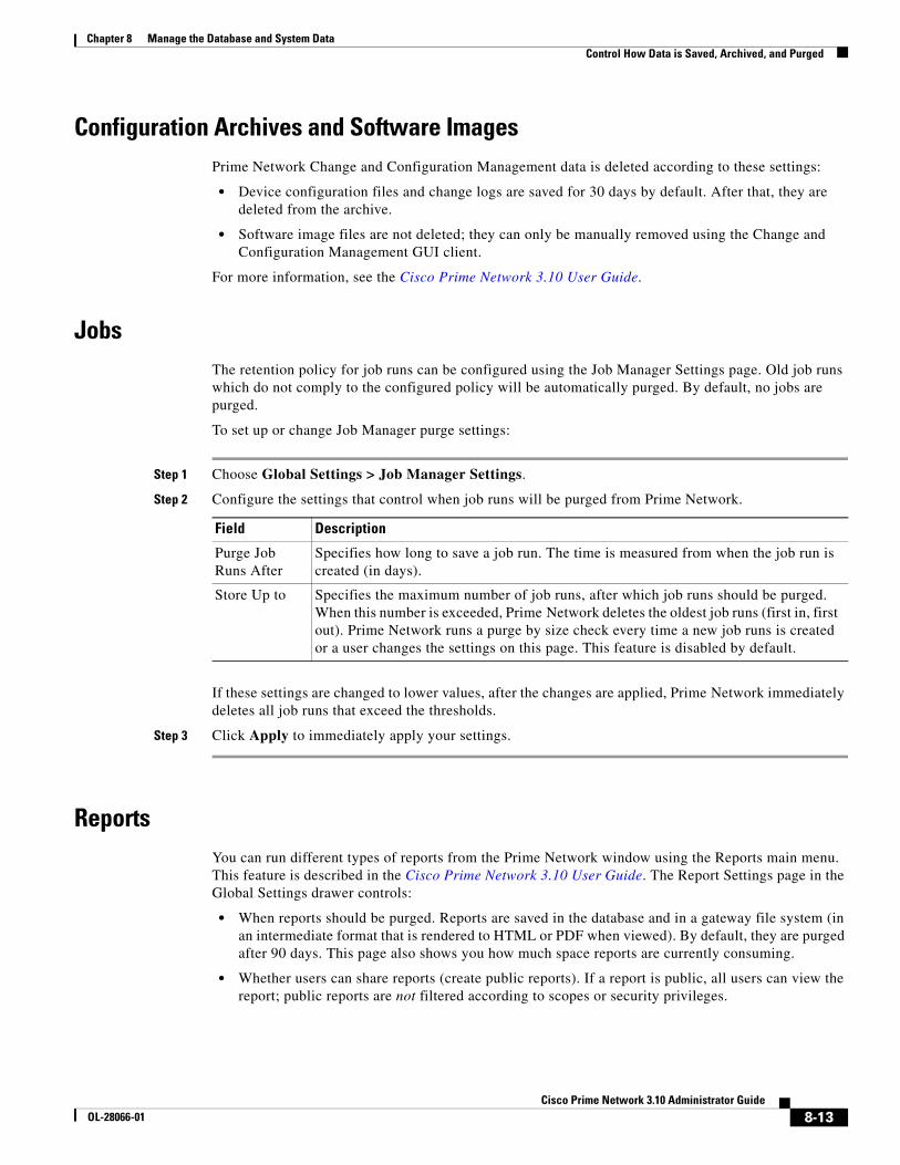
8-13Cisco Prime Network 3.10 Administrator Guide
OL-28066-01
Chapter 8 Manage the Database and System Data Control How Data is Saved, Archived, and Purged
Configuration Archives and Software ImagesPrime Network Change and Configuration Management data is deleted according to these settings:
• Device configuration files and change logs are saved for 30 days by default. After that, they are deleted from the archive.
• Software image files are not deleted; they can only be manually removed using the Change and Configuration Management GUI client.
For more information, see the Cisco Prime Network 3.10 User Guide.
JobsThe retention policy for job runs can be configured using the Job Manager Settings page. Old job runs which do not comply to the configured policy will be automatically purged. By default, no jobs are purged.
To set up or change Job Manager purge settings:
Step 1 Choose Global Settings > Job Manager Settings.
Step 2 Configure the settings that control when job runs will be purged from Prime Network.
If these settings are changed to lower values, after the changes are applied, Prime Network immediately deletes all job runs that exceed the thresholds.
Step 3 Click Apply to immediately apply your settings.
ReportsYou can run different types of reports from the Prime Network window using the Reports main menu. This feature is described in the Cisco Prime Network 3.10 User Guide. The Report Settings page in the Global Settings drawer controls:
• When reports should be purged. Reports are saved in the database and in a gateway file system (in an intermediate format that is rendered to HTML or PDF when viewed). By default, they are purged after 90 days. This page also shows you how much space reports are currently consuming.
• Whether users can share reports (create public reports). If a report is public, all users can view the report; public reports are not filtered according to scopes or security privileges.
Field Description
Purge Job Runs After
Specifies how long to save a job run. The time is measured from when the job run is created (in days).
Store Up to Specifies the maximum number of job runs, after which job runs should be purged. When this number is exceeded, Prime Network deletes the oldest job runs (first in, first out). Prime Network runs a purge by size check every time a new job runs is created or a user changes the settings on this page. This feature is disabled by default.

8-14Cisco Prime Network 3.10 Administrator Guide
OL-28066-01
Chapter 8 Manage the Database and System Data Control How Data is Saved, Archived, and Purged
The settings do not affect user permissions for report actions such as adding, deleting, canceling, and so forth. Users can still perform all actions on reports they create; they can view other reports only if the reports are public. Administrators are the only users who can perform all actions on all reports.
Note We recommend that you use these default settings in order to reduce system clutter. Allowing report data to accumulate could affect system performance.
To set up or change global report settings:
Step 1 Choose Global Settings > Report Settings.
Step 2 Configure the settings that control when reports will be purged from Prime Network, using dates, size, or both.
If these settings are changed to lower values, after the changes are applied, Prime Network immediately deletes all reports that exceed the thresholds.
Step 3 The Enable Shared Reports check box specifies whether users can create public reports. When a report is public, all users can view the contents; reports are not filtered according to scopes or security privileges. Changes to this setting are applied to all subsequent new reports.
• If not selected, no users will be able to create public reports. Users will only be able to view their own reports.
• If selected, users have the option to create public reports and share them with other users.
Step 4 Click Apply to immediately apply your settings.
After you click Apply, the report settings are applied to all existing and new reports. You can restore the Prime Network default settings at any time by clicking Restore and Apply.
Workflows and ActivationsAll templates, workflows, and activations are saved in the database under the pnuser_dwe schema. All executed workflow and activation instances are purged according to the MAX_WORKFLOW_AGE_ENTRY. By default, this entry is set to 7, which means activation instances are deleted after 7 days. Purging is done according to the integrity test listed in Table 8-4 on page 8-7.
Templates can only deleted from the Administration GUI client or by using a BQL command. How to do this from the GUI client is described in Manage Workflow and Activation Templates, page 10-4.
Field Description
Purge report after: ___ days
Specifies how long to save a report. The time is measured from when the report is created. If you do not check this box, Prime Network defaults to 90 days. The Prime Network integrity service runs a job every 12 hours to purge all reports that exceed this age.
Store reports up to: ___ MB
Specifies the maximum disk size, in MB, at which reports should be purged. When this space setting is exceeded, Prime Network deletes the oldest reports (first in, first out). Prime Network runs a purge by size check every time a new report is created or a user changes the settings on this page. This feature is disabled by default.

8-15Cisco Prime Network 3.10 Administrator Guide
OL-28066-01
Chapter 8 Manage the Database and System Data Manage an Embedded Database
Diagnostic Data (Graphs Tool)Data gathered by the Prime Network Monitoring tool is purged after 28 days as described in Prevent System Overloads (Advanced Overload Prevention/Safe Mode), page 8-23.
BackupsPrime Network performs backups on a regular basis for Prime Network data and embedded databases. For more information, see Back Up and Restore Process, page 2-9.
Number of backups saved for Prime Network are as follows:
• Backups of embedded database: 8 days
• Backups of Prime Network data:
– Installations with external databases: 16 backups
– Installations with embedded databases: 16 backups
Manage an Embedded DatabasePrime Network performs regular checks to ensure the health of the embedded database. Prime Network also provides native utilities for adding storage, collecting database logs and reports, and other maintenance tasks. These are all described in the following topics:
• Overview: How Prime Network Monitors an Embedded Database, page 8-15
• Embedded Database Events and Errors, page 8-16
• Stop, Start, and Change Embedded Database Settings (embdctl Utility), page 8-18
• Change the SMTP Server for Embedded Database Notifications, page 8-22
Overview: How Prime Network Monitors an Embedded DatabasePrime Network performs regular maintenance checks and backups for embedded databases. Backups are enabled as part of the installation process. If you did not enable backups, you can do so using the procedure in Back Up and Restore Process, page 2-9. That topic also provides information on backup schedules, how many backups are saved, and the backup location.
Table 8-8 lists the regular maintenance checks performed by Prime Network.

8-16Cisco Prime Network 3.10 Administrator Guide
OL-28066-01
Chapter 8 Manage the Database and System Data Manage an Embedded Database
Embedded Database Events and ErrorsPrime Network monitors the embedded database and generates System events when necessary.
Database Disk Usage Alerts
Prime Network will continue to generate events (one hour later, at the next cron job) if the same directory’s disk usage surpasses the next threshold, or a different directory’s disk usage surpasses any threshold. If the disk space is unchanged, no new System events are generated.
If the problem continues:
1. Ask your system administrator to add disk space to the relevant file systems.
2. If more disk space cannot be added, contact the Cisco Technical Assistance Center for information on how to reduce history size. This will not change the disk usage, but will eliminate the need to add disk space.
Database Tablespace Usage Alerts
Note You can change the thresholds by editing the TS_ALERTS.prm file. Prime Network will use the new threshold numbers when it performs the next hourly cron job.
Table 8-8 Cron Jobs for Maintaining the Embedded Database
Cron Job Task Description
Monitor disk usage on database server
Hourly job that checks database disk usage (on server host) for data files, redo logs, backup files, and so on. If any directory exceeds a threshold, an e-mail and System event is sent. Event severity depends on threshold:
• 50-70%—Warning event
• 70-80%—Minor event
• 80% and above—Major event
See Database Disk Usage Alerts, page 8-16, for additional information about this problem.
Check available space in tablespaces
Hourly job that checks whether tablespaces listed in NETWORKHOME/Main/scripts/embedded_db/cron/TS_ALERTS.prm. If threshold is exceeded, a new data file is added to tablespace, and an e-mail and System event is sent. Event severity depends on threshold:
• 80-90%—Minor event
• 90% and above—Major event
See Database Tablespace Usage Alerts, page 8-16, for additional information about this problem.
Check database backup log for errors
Daily job that checks backup logs for errors. Removes logs over 14 days old.
Clean database log and trace files
Hourly job that removes database log and trace files more than 31 days old.

8-17Cisco Prime Network 3.10 Administrator Guide
OL-28066-01
Chapter 8 Manage the Database and System Data Manage an Embedded Database
If a tablespace exceeds its capacity, Prime Network will add a new data file to the tablespace. Prime Network will generate an hourly system event until the problem is fixed. If the problem continues, do the following:
1. If you have the required disk space, add data files using the add_storage_for_tablespace.pl utility. See Add Datafiles to a Specific Tablespace (add_storage_for_tablespace.pl), page 8-21.
2. Contact the Cisco Technical Assistance Center.
Oracle Errors Monitored by Prime Network
Table 8-9 lists the Oracle errors that are monitored by Prime Network. If you receive any of the following errors, contact the Cisco Technical Assistance Center (TAC).
Table 8-9 Oracle Database Function Error Messages
Error Code and Message Possible Reason
ORA-00600internal error code, arguments: [string], [string], [string], [string], [string], [string], [string], [string]
This is the generic internal error number for Oracle program exceptions. This indicates that a process has encountered an exceptional condition.
ORA-00604error occurred at recursive SQL level string
An error occurred while processing a recursive SQL statement (a statement applying to internal dictionary tables).
ORA-00050operating system error occurred while obtaining an enqueue
Could not obtain the operating system resources necessary to cover an oracle enqueue. This is normally the result of an operating system user quota that is too low.
ORA-00052maximum number of enqueue resources (string) exceeded
Ran out of enqueue resources.
ORA-00053maximum number of enqueues exceeded
Ran out of enqueue state objects.
ORA-00055maximum number of DML locks exceeded
Ran out of DML lock state objects.
ORA-00059maximum number of DB_FILES exceeded
The value of the DB_FILES initialization parameter was exceeded.
ORA-00060deadlock detected while waiting for resource
Transactions deadlocked one another while waiting for resources.
ORA-00250archiver not started
An attempt was made to stop automatic archiving, but the archiver process was not running.
ORA-00255error archiving log string of thread string, sequence # string
An error occurred during archiving.
ORA-00257archiver error. Connect internal only, until freed.
The archiver process received an error while trying to archive a redo log. If the problem is not resolved soon, the database will stop executing transactions. The most likely cause of this message is the destination device is out of space to store the redo log file.
ORA-01033ORACLE initialization or shutdown in progress
An attempt was made to log on while Oracle is being started up or shutdown.
ORA-01035ORACLE only available to users with RESTRICTED SESSION privilege
Logins are disallowed because an instance started in restricted mode. Only users with RESTRICTED SESSION system privilege can log on.

8-18Cisco Prime Network 3.10 Administrator Guide
OL-28066-01
Chapter 8 Manage the Database and System Data Manage an Embedded Database
Stop, Start, and Change Embedded Database Settings (embdctl Utility)
Note If you are using gateway server high availability, freeze the cluster services before using emdbctl with the stop, start, restore, restore_db, or enable_backup options. These options will stop and restart the cluster services. If the cluster is running and detects that the services are down, it may attempt to restart them. When used with Oracle ADG, reconfigure the database replication after restoring the primary DB. For more information on replication process, see Cisco Prime Network 3.10 Gateway High Availability Guide.
Use the emdbctl command to perform embedded database backup and restore operations, collect logs and reports, and other administrative actions. The emdbctl command is located in NETWORKHOME/Main/scripts/embedded_db. It takes the following options:
emdbctl [ --start | --stop | --enable_backup | --backup | --restore | --restore_db| --collect | --change_backup_time | --set_smtp_server ]
ORA-01110data file string: (string)
Reports the file name. This error accompanies other errors that explain the problem associated with this file.
ORA-01116error in opening database file (string)
At attempt e to open a database file failed. Most likely the file is inaccessible. Accompanying errors will provide the file name.
ORA-01520number of data files to add (string) exceeds limit of string
CREATE TABLESPACE statement specifies more files than is permitted for this database.
ORA-01536space quota exceeded for tablespace 'string'
The space quota for the segment owner in the tablespace has been exhausted and the operation attempted the creation of a new segment extent in the tablespace.
ORA-01659unable to allocate MINEXTENTS beyond string in tablespace string
Failed to find sufficient contiguous space to allocate MINEXTENTS for the segment being created.
ORA-27041Unable to open file
An attempt to open a file failed. Check the accompanying error messages for the file name.
ORA-27100shared memory realm already exists
Tried to start duplicate instances, or tried to restart an instance that had not been properly shutdown.
ORA-27102out of memory
—
ORA-27103internal error
—
ORA-27146post/wait initialization failed
OS system call failed.
Table 8-9 Oracle Database Function Error Messages (continued)
Error Code and Message Possible Reason

8-19Cisco Prime Network 3.10 Administrator Guide
OL-28066-01
Chapter 8 Manage the Database and System Data Manage an Embedded Database
You must be logged in as pnuser to use this command.
The following illustrates how to use the start and stop options:
# emdbctl --stopStopping Prime NetworkStopping NCCM DM Server...- DM server is up, about to shut it down- Sent graceful shutdown command to the dm Server (pid 25499), waiting for 2 seconds- Checking if DM server is still up (1st)- The DM Server is downAVM unregistered successfullyStopping AVMs.....Done.Stopping the database and listener## emdbctl --start
- Starting the database and listener- Starting MVM..........................................................Done.- Starting Gateway ..............................................................Done.
Option Description See:
--stop Stops Prime Network on the gateway and units, and stops the embedded database services and listener.
This topic for examples.
--start Starts the embedded database services and listener, and starts Prime Network on the gateway and units (if the units are down).
--enable_backup Enables the automatic backup mechanism. Enable Embedded Database Backups, page 2-14
--backup Backs up the embedded database and Prime Network, including the registry.
Back Up and Restore Process, page 2-9
--restore Restores the embedded database and Prime Network, including the registry using valid backup files.
Back Up and Restore Process, page 2-9
--restore_db Restores the embedded database only.
--collect Collects embedded database logs and reports. It collects logs and trace files from the database server, runs a database diagnostic tool, zips the output together, and copies it to the gateway at NETWORKHOME/Main/logs/emdb/ana_collector.zip. It can be run alone or as part of the artifacts of the ANA Profiler Tool (available from the Cisco Developer Network).
n/a
--change_backup_time
Allows to change the database backup time. Change the Embedded Database Backup Schedule, page 2-15
--set_smtp_server Changes the SMTP server for e-mail notifications from the database.
This topic for an example.
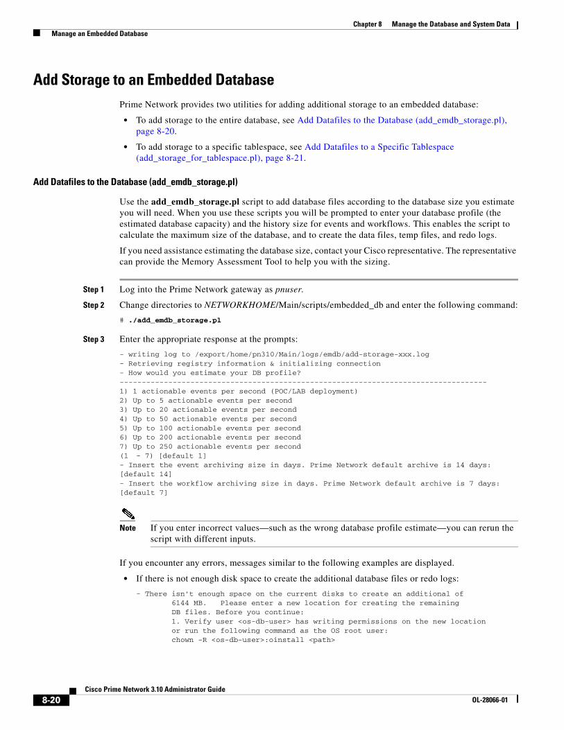
8-20Cisco Prime Network 3.10 Administrator Guide
OL-28066-01
Chapter 8 Manage the Database and System Data Manage an Embedded Database
Add Storage to an Embedded DatabasePrime Network provides two utilities for adding additional storage to an embedded database:
• To add storage to the entire database, see Add Datafiles to the Database (add_emdb_storage.pl), page 8-20.
• To add storage to a specific tablespace, see Add Datafiles to a Specific Tablespace (add_storage_for_tablespace.pl), page 8-21.
Add Datafiles to the Database (add_emdb_storage.pl)
Use the add_emdb_storage.pl script to add database files according to the database size you estimate you will need. When you use these scripts you will be prompted to enter your database profile (the estimated database capacity) and the history size for events and workflows. This enables the script to calculate the maximum size of the database, and to create the data files, temp files, and redo logs.
If you need assistance estimating the database size, contact your Cisco representative. The representative can provide the Memory Assessment Tool to help you with the sizing.
Step 1 Log into the Prime Network gateway as pnuser.
Step 2 Change directories to NETWORKHOME/Main/scripts/embedded_db and enter the following command:
# ./add_emdb_storage.pl
Step 3 Enter the appropriate response at the prompts:
- writing log to /export/home/pn310/Main/logs/emdb/add-storage-xxx.log- Retrieving registry information & initializing connection- How would you estimate your DB profile?-----------------------------------------------------------------------------------1) 1 actionable events per second (POC/LAB deployment)2) Up to 5 actionable events per second3) Up to 20 actionable events per second4) Up to 50 actionable events per second5) Up to 100 actionable events per second6) Up to 200 actionable events per second7) Up to 250 actionable events per second(1 - 7) [default 1]- Insert the event archiving size in days. Prime Network default archive is 14 days: [default 14]- Insert the workflow archiving size in days. Prime Network default archive is 7 days: [default 7]
Note If you enter incorrect values—such as the wrong database profile estimate—you can rerun the script with different inputs.
If you encounter any errors, messages similar to the following examples are displayed.
• If there is not enough disk space to create the additional database files or redo logs:
- There isn't enough space on the current disks to create an additional of 6144 MB. Please enter a new location for creating the remaining DB files. Before you continue: 1. Verify user <os-db-user> has writing permissions on the new location or run the following command as the OS root user: chown -R <os-db-user>:oinstall <path>

8-21Cisco Prime Network 3.10 Administrator Guide
OL-28066-01
Chapter 8 Manage the Database and System Data Manage an Embedded Database
2. Verify the new location is mounted as UFS with 'forcedirectio' option
New location:
Enter another location.
• If the files or redo logs cannot be created for any reason, you will see an error message and the following prompt:
- How would you like to continue?---------------------------------1) Retry 2) Skip (move to the next in list)3) Abort (1 - 3) [default 1]
For example, if the correct permissions were not set, you would see the following.
Failed to add datafile for pn310:-1119: ORA-01119: error in creating database file '/2del/pn310_DATA11.dbf'ORA-27040: file create error, unable to create fileLinux-x86_64 Error: 13: Permission denied
The menu choices provide you with an opportunity to fix the permissions and retry creating the file or log.
The log file is located in NETWORKHOME/Main/logs/emdb/add-storage-time-stamp.log.
Add Datafiles to a Specific Tablespace (add_storage_for_tablespace.pl)
Use the add_storage_for_tablespace.pl script to add database files to a specific tablespace. If a tablespace exceeds its capacity, Prime Network will add a new data file to the tablespace and generate an hourly system event until the problem is fixed.
The command is located in NETWORKHOME/Main/scripts/embedded_db. It takes the following arguments:
add_storage_for_tablespace.pl --tablespace tablespace_name --space additional_space_required (MB) --location location_for_new_files
The log file is located in NETWORKHOME/Main/logs/emdb/add-storage-to_tbs-timestamp.log.
Before You Begin
You will need the following information to use this script:
• The name of the tablespace that requires more datafiles.
• Additional space required for the above tablespace.
• The full directory name where the new datafiles will be created.
The following examples add 100 MB to the pn310 tablespace located in /export/home/oracle/oradata/anadb. This command performs the operation in one command line:
# ./add_storage_for_tablespace.pl --tablespace pn310 --space 100 --location /export/home/oracle/oradata/anadb/

8-22Cisco Prime Network 3.10 Administrator Guide
OL-28066-01
Chapter 8 Manage the Database and System Data Manage an Embedded Database
This procedure adds the tablespace using interactive mode:
Step 1 Log into the Prime Network gateway as pnuser.
Step 2 Change directories to NETWORKHOME/Main/scripts/embedded_db and enter the following command:
# ./add_storage_for_tablespace.pl
Step 3 Enter the appropriate response at the prompts:
This script will add an additional datafile for a certain tablespace in the DB----------------------------------------------------------------------------------
+Retrieving registry information & initializing connection+Choose one of the following Prime Network tablespaces to add datafiles to:
TABLESPACE_NAME FREE_SPACE_MB------------------------------ -------------UNDOTBS1 1992.25pn310_DWE 1018.375pn310_XMP 1009.625pn310_EP 928.6875pn310 271.8125pn310_ADMIN 98.375SYSAX 37.375SYSTEM 6.75USERS 3.6875
- Enter tablespace name: pn310
+Choose one of the following locations for the new datafile/s to be created at:/export/home/oracle/oradata/anadb/- Enter location: /export/home/oracle/oradata/anadb/
- Enter the required size in MB (For Example: 1000): 100
+About to add 100 MB to pn310 on /export/home/oracle/oradata/anadb/Successfully added 100 M on /export/home/oracle/oradata/anadb/ to pn310
Change the SMTP Server for Embedded Database NotificationsIf necessary, you can change the SMTP server for e-mail notifications from the embedded database using the embdctl command, as shown in this example.
# emdbctl --set_smtp_serverEnter your SMTP server IP/Hostname: 1.1.1.1Verifying connectivity to 1.1.1.1 Failed to connect to 1.1.1.1 on port 25. Please try againEnter your SMTP server IP/Hostname: outbound.cisco.comVerifying connectivity to outbound.cisco.comReading Prime Network registryUpdating the SMTP server parameter in the databaseDone

8-23Cisco Prime Network 3.10 Administrator Guide
OL-28066-01
Chapter 8 Manage the Database and System Data Prevent System Overloads (Advanced Overload Prevention/Safe Mode)
Prevent System Overloads (Advanced Overload Prevention/Safe Mode)
Prime Network uses a software mechanism called Automatic Overload Prevention (AOP) to detect and prevent system overload. The AOP service monitors the load produced by components in Prime Network. Similar components, such as those that control fault management, are grouped together into an AOP subsystem. When a subsystem’s processing load becomes heavy, the whole system moves into safe mode. Other subsystems respond by adjusting their processing in order to prevent system overload. When this happens, a System event is generated and can be viewed in Prime Network EventVision.
If the subsystem continues to be overloaded, the components will take other measures to lessen the system load (if those measures are configured). As soon as the problematic subsystem returns to a normal load, all other components revert to normal.
The AOP mechanism is currently used by the following subsystems, due to the very large amount of data they process:
• Reporting subsystem.
• Fault subsystem, which includes the Alarm Plugin, Global Event Filter Agent, Event Integrity Agent, and Ticket Agent.
Loads and Running Levels
The AOP service maintains the following information about each component in a subsystem.
When a problem occurs and a component’s load increases, the following can occur, depending on your system configuration:
• The reporting subsystem disabled reports (at AOP 6, by default).
• The Alarm Plugin stops auto-clearing events (at AOP 6, by default).
• The Global Event Filter drops some syslogs and traps (it does this at all AOP levels, and at AOP 6, it drops all syslogs and traps).
To specify which events the fault subsystem drops at different running levels, see Configuring the AOP Global Event Filter, page 8-24.
Load Indicator Definition
Current Load Current processing load. When a component’s Current Load changes, other components may respond by changing their Current Loads and/or Running Levels. Supported Current Loads are:
• NORMAL
• LOADx (safe mode), where x is 1-6
Running Level The state in which a component is running. Running Levels can change in response to Current Load and/or Running Level changes in other components. Supported Running Levels are:
• NORMAL, also called Running Level 0.
• AOPx or safe mode, where x is Running Levels 1-6.

8-24Cisco Prime Network 3.10 Administrator Guide
OL-28066-01
Chapter 8 Manage the Database and System Data Prevent System Overloads (Advanced Overload Prevention/Safe Mode)
Note Dropping syslogs and traps in this context means that syslogs and traps are not correlated and forwarded to the Fault Agent (AVM 25); syslogs and traps are still sent to the Event Archive (if enabled). Also note that only syslogs and traps are dropped; Service events and non-network events (Audit, Security, System, and Provisioning events) are never dropped by the AOP mechanism.
As soon as the load returns to normal on the problematic component, all components respond by returning to normal and the system moves out of safe mode.
Displaying Current AOP Loads and Running Levels
To display the status of all components that are using AOP:
Step 1 Open an SSH session to the Prime Network gateway server and log in as pnuser.
Step 2 Enter the following:
# telnet 0 2011Connected to 0.Sheer BOS AVM managementAVM11#/>cd aopAVM11#aop>getAOPStatus------------------------------------------------------------------------------------------Subsystem ComponentId Load Running Level Last Modification Time------------------------------------------------------------------------------------------FAULT ALARM_PLUGIN NORMAL AOP6 Thu Oct 21 13:20:20 PST 2011FAULT EVENT_GLOBAL_FILTER_AGENT NORMAL AOP1 Thu Oct 21 13:20:20 PST 2011FAULT EVENTINTEGRITY_AGENT NORMAL AOP1 Thu Oct 21 13:20:20 PST 2011FAULT TICKET_AGENT LOAD1 NORMAL Thu Oct 21 13:20:20 PST 2011REPORTS REPORTS_AGENT NORMAL AOP6 Thu Oct 21 13:20:17 PST 2011------------------------------------------------------------------------------------------total rows in report: 5
Configuring the AOP Global Event Filter
The Event Global Filter has two flavors:
• Filtering when the system is running in NORMAL mode (Running Level 0)
• Filtering when the system is in AOP mode (Running Levels AOP 1-6)
You can define filters for Running Levels 0-5—that is, for NORMAL mode, and for AOP 1-5. At Running Level 6, all traps and syslogs are dropped so no further filtering is useful.
The filter contains a list of rules that define what events should be excluded. Events are assigned a number (1-6), corresponding to the AOP running levels. When the AOP running level is x, all events with a number equal to or lesser than x are dropped. Note that this is done after events are sent to the Event Archive (if enabled).
Use the following procedure to create a new filter. In this procedure you will specify:
• Running level at which to drop the events that match the filter.
• The event information. When matched, the event will be dropped.

8-25Cisco Prime Network 3.10 Administrator Guide
OL-28066-01
Chapter 8 Manage the Database and System Data Prevent System Overloads (Advanced Overload Prevention/Safe Mode)
To create a new filter, use this procedure. For information on the properties described in the procedure, see the Cisco Prime Network Integration Developer Guide.
Step 1 Log into the Prime Network gateway server as pnuser.
Step 2 Add the new filter information to the registry using the following command.
ID is the AOP running level at which to drop events if they match the filter criteria, and propertyName is the event attribute to be checked by the filter:
# ./runRegTool.sh -gs 127.0.0.1 add 0.0.0.0 site/event-global-filter/runningLevelID/propertyName
propertyName can be any of the following:
This command adds a SeverityEnum property value to AOP 1:
# ./runRegTool.sh -gs 127.0.0.1 add 0.0.0.0 site/event-global-filter/runningLevel1/SeverityEnum
Step 3 Set a value for the event property. Events will be dropped when the property has that value.
# ./runRegTool.sh -gs 127.0.0.1 set 0.0.0.0 site/event-global-filter/runningLevelID/propertyName/propertyValue “”
This command sets the SeverityEnum value to 1 in the Global Event Filter:
# ./runRegTool.sh -gs 127.0.0.1 set 0.0.0.0 site/event-global-filter/runningLevel1/SeverityEnum/1 “”
Attribute Description and Supported Values
SeverityEnum An integer that represents the severity. Supported SeverityEnums are:
1—INFO2—CLEARED3—WARNING4—MINOR5—MAJOR6—CRITICAL
Name An integer that represents the alarm as defined in the alarm-types.xml registry file. For example, 1 represents “Link Down.”
State Short description of the event, such as “Port down due to card down.”
DetectionType An integer that represents the event protocol type. Supported DetectionTypes are:
0—Service Event1—Syslog Event2—V1 Trap3—V2 Trap4—V3 Trap

8-26Cisco Prime Network 3.10 Administrator Guide
OL-28066-01
Chapter 8 Manage the Database and System Data Track Database and System Integrity Events
To remove a filter, use this procedure.
Step 1 Log into the Prime Network gateway server as pnuser.
Step 2 Remove the filter from the registry using the following command.
ID is the AOP running level at which to drop events if they match the filter criteria, and propertyName is the event attribute to be checked by the filter:
# ./runRegTool.sh -gs 127.0.0.1 remove 0.0.0.0 site/event-global-filter/runningLevelID/propertyName “”
This command removes the filter created in the previous procedure:
# ./runRegTool.sh -gs 127.0.0.1 remove 0.0.0.0 site/event-global-filter/runningLevel1/SeverityEnum “”
Track Database and System Integrity EventsThe following predefined reports can provide you with important database statistics for a period of time that you specify. To run any of these reports, select Reports > Run Report > Events Reports and choose the report name.
Report Name Provides the following info for a specified period:
Fault DB vs. Event Archive Statistics
Lists the total number of these types of events for a specified time period: Syslogs, traps, tickets, correlated and uncorrelated events, network events, non-network events, and service events
Database Monitoring (includes events per second)—How many of the following occurred in the specified time period: Active tickets, active alarms, and active events; large tickets (and their event counts); notifications. You can also get the event rate per second for that period.
Detailed System Events Lists all System events for the gateway server, such as ticket archiving, tablespace, partitioning, dropping events, and AOP events

C H A P T E R
9-1Cisco Prime Network 3.10 Administrator Guide
OL-28066-01
9Control Event Monitoring
These topics explain how to set up and configure event monitoring in Prime Network. This includes configuring the Event Collector (which listens for incoming events), with examples for a variety of different system configurations, and how to set up trap and e-mail notifications.
• How Prime Network Handles Incoming Events, page 9-1
• Configure the Event Collector to Listen for Incoming Events, page 9-6
• Configure Trap and E-Mail Notifications (Event Notification Service), page 9-16
• Configure System TCAs, page 9-22
• Track Events, page 9-23
How Prime Network Handles Incoming EventsWhen a trap or syslog is sent from a device to Prime Network, it is received by the Event Collector, which runs on AVM 100. Figure 9-1 illustrates how Prime Network responds to incoming notifications from devices. The exact flow depends on how Prime Network is configured in your network.
Note Figure 9-1 illustrates the logical flow of events through Prime Network. The actual network communication is subject to the transport configuration between the gateway server and units.

9-2Cisco Prime Network 3.10 Administrator Guide
OL-28066-01
Chapter 9 Control Event Monitoring How Prime Network Handles Incoming Events
Figure 9-1 How Prime Network Responds to Incoming Notifications from Devices
Figure 9-1 also illustrates the two entities that store fault information, both of which reside in the Prime Network database:
• Event Archive—Contains all raw events (traps, and syslogs) received from devices. The Event Archive also stores information from unmanaged devices (if notification from unmanaged devices is enabled; see the Cisco Prime Network Integration Developer Guide). The database schema name is pnuser_ep. For example, if pnuser is pn310, the Event Archive database schema is named pn310_ep.
You can only view information in the Event Archive using the reports mechanism. Event archiving is enabled by default, but you can disable it using the procedure in Disable Saving Raw Events to the Event Archive, page 8-12.
• Fault Database—Contains all the actionable events (events that Prime Network knows how to parse and can therefore participate in correlation). The Fault Database also contains information such as tickets, alarms, and severity information. The Fault Database schema name is pnuser. For example, if pnuser is named pn310, the main schema is called pn310.
You can view information in the Fault Database using the Prime Network Events and Vision GUI clients.
The Event Archive and Fault Database data is archived and saved according to the settings in the Global Settings > Event Management Settings window in the Prime Network Administration GUI client. (See Events, Alarms, and Tickets, page 8-8.)
The following topics describe how the Event Collector, VNEs, and the Fault Agent (AVM 25) work together to process incoming notifications from devices. For more details about the event flow illustrated in Figure 9-1, see the Cisco Prime Network Integration Developer Guide.

9-3Cisco Prime Network 3.10 Administrator Guide
OL-28066-01
Chapter 9 Control Event Monitoring How Prime Network Handles Incoming Events
Event Collector (AVM 100)
The Event Collector is the first receiver for incoming event notifications from devices. It is an internal service that is part of AVM 100. During installation, Event Collectors are created on the gateway and all units, but a single Event Collector AVM is started only on the gateway. By default, all new VNEs will register with the Event Collector on the gateway server. This Event Collector has the internal address 0.0.0.0 (this address is not related to the device IP address).
Note If desired, you can configure a filter that will drop “pure noise” at the Event Collector level. In other words, this filter will drop all raw events before any processing or archiving is done; the events are not processed by VNEs or forwarded using the Event Notification Service. Complete instructions for configuring this type of filter is provided on the Cisco Developer Network at http://developer.cisco.com/web/prime-network/home. (This is different from the global event filter that drops events at the VNE level when the system moves into safe mode; see Configuring the AOP Global Event Filter, page 8-24.)
When an event, trap, or syslog is received by the Event Collector, the Event Collector does the following:
1. Performs initial parsing to obtain basic information about each event.
2. (If a global filter is implemented) Filters out (drops) any events that match the filter. By default, no filters are implemented. To configure a filter, see Configuring the AOP Global Event Filter, page 8-24.
3. Stores all events, traps, and syslogs in the Event Archive. Events are saved in the Event Archive only if the device has corresponding VNE which is registered to the Event Collector. If a syslogs is sent as an SNMP trap by way of the CISCO-SYSLOG-MIB, the Event Collector interprets it to be a syslog.(To save events from unmanaged devices, see the procedure in the Cisco Prime Network Integration Developer Guide.)
4. Forwards events from unmanaged devices to the Event Notification Service, if an ENS is configured. (See Configure Trap and E-Mail Notifications (Event Notification Service), page 9-16.)
5. Distributes each event to its corresponding VNE (if the VNE is registered with the Event Collector).
The Event Collector AVM requires a database connection when event archiving is enabled. If event archiving is disabled, a connection to the database is not required. To disable or reenable event archiving, see Disable Saving Raw Events to the Event Archive, page 8-12.
Event Collector and Unit Server High Availability
You can configure the Event Collector to run on a unit instead of the gateway. If the unit is also configured with unit server high availability, the Event Collector on the standby unit will drop all events because the Event Collector is disabled. This is by design; it should not start until a switchover occurs.
The standby unit contains a port watchdog script that listens for events on the unit’s Syslog and SNMP ports. The script prevents unnecessary ICMP unreachable messages being sent back to the network. If a switchover occurs, the standby unit and Event Collector AVM will start, and the watchdog script releases the ports.
When the original unit comes back up, the standby Event Collector AVM goes back down, and the watchdog script recommences listening on the standby unit’s Syslog and SNMP ports.

9-4Cisco Prime Network 3.10 Administrator Guide
OL-28066-01
Chapter 9 Control Event Monitoring How Prime Network Handles Incoming Events
Note If the Cisco Prime Performance Manager application is also installed (with Prime Central), the Prime Network Event Collector will receive threshold crossing alarm (TCA) events from Prime Performance Manager components and do the following:
• Save TCA events in the Event Archive.
• Forward TCA events to appropriate VNEs. The events are currently not parsed by the VNE. They will be identified as generic traps and will be dropped. If desired, you can forward them to an Event Notification Service (see Configure Trap and E-Mail Notifications (Event Notification Service), page 9-16).
No special configuration is required.
Prime Network also receives EPM-MIB traps from the network. By default Prime Network receives EPM-MIB traps from any source in the network. If desired, you can configure Prime Network to only process EPM-MIB traps arriving from a specific Prime Performance Manager server. The instructions for doing this are provided on the Cisco Developer Network at http://developer.cisco.com/web/prime-network/home.
VNEs
When a VNE receives an event from the Event Collector, the VNE does the following:
1. Determines whether an event is actionable or non-actionable.
Actionable events are events that the VNE can match with a predefined pattern. The VNE attempts to extract information from the raw event (the source, the problem, and the severity).
Non-actionable events are events that the VNE cannot match with a predefined pattern. These are also called generic events.
2. Associates the event to its NE (for example, associating a port down to a device’s physical interface).
3. Filters the information to determine if it is a physical interface for which alarms are disabled
4. If the event is actionable, correlates the event and, if possible, identifies a root cause.
For non-actionable events, the VNE takes no further action unless you have configured an Event Notification Service to forward the events to OSSs or e-mail recipients (see Configure Trap and E-Mail Notifications (Event Notification Service), page 9-16).
5. Sends the parsed event and correlation information to AVM 25 to be saved to the Fault Database. The Fault Database also contains information such as tickets, alarms, and severity information.
These actions are performed by a process within the VNE called the event manager, which is responsible for handling all network events, whether they are syslogs or traps, discovered during normal polling, or threshold-crossing alarms.
VNEs must be registered with an Event Collector’s internal address (this address is not related to the device IP address). When a VNE is first initialized, the following occurs:
• The VNE reads this Event Collector’s internal address from the registry. By default, all new VNEs will register with the Event Collector on the gateway server. This Event Collector has the internal address 0.0.0.0.
• The VNE registers its management IP address with this Event Collector.
If the Event Collector receives a trap or syslog, and the trap or syslog’s source IP address matches the VNE’s management IP address, the Event Collector will forward the syslogs or trap to that VNE.

9-5Cisco Prime Network 3.10 Administrator Guide
OL-28066-01
Chapter 9 Control Event Monitoring How Prime Network Handles Incoming Events
A VNE may have more than one IP address registered with the Event Collector, such as when a device is using other IP addresses as sources for syslogs or traps). These IP addresses can be discovered automatically from the device configuration but can also be manually configured using the VNE Event settings in Prime Network Administration (see VNE Properties: Events, page D-17).
AVM 25 (Fault Agent)
When a VNE forwards an event to AVM 25, the Fault Agent does the following:
1. Saves the information to the Fault Database (including events that are not ticketable or could not be correlated).
2. If the new event is connected to an existing ticketed event, the new event is assigned the same ticket ID and alarm ID as the existing event. Otherwise a new ticket is created based on the correlation information and event type.
Event types are configured as ticketable in the registry. Prime Network will create a ticket for ticketable events, even if they are non-correlated events.
A trap or syslogs generates a ticket if:
– It does not correspond to another event
– It is a ticketable event (as defined in the registry)
Note A ticketable event is an event that describes a problem that needs to be handled.
3. If an event is ticketable, it is displayed in the Vision GUI client. All events associated with a ticket are displayed in the Vision GUI client (even if the associated events are not defined as ticketable in the registry). In the Latest Events tab you can view both ticketable and non ticketable events.
AVM 25 requires a database connection to store information in the Fault Database so that it can be subsequently viewed in Prime Network Events. If a direct connection is not available, you can configure AVM 25 without connectivity to forward its events to another AVM 25 that does have a database connection. This is called using a proxy AVM 25. How to do so is described in Configuring Proxy AVM 25 for Units Not Connected to Database, page 9-15.
Keep these items in mind when starting and stopping AVM 25:
• Avoid stopping AVM 25 to make sure that Prime Network does not drop events.
• If you stop and restart AVM 25, you do not have to restart user-created AVMs.
• User-created AVMs will not start if AVM 25 is not running; they will be Unreachable.
Example of Full Event Flow
The following steps show the flow of events when Device A sends a Port Down notification to the Event Collector.
1. The Event Collector receives the notification and persists the Port Down event to the Event Archive. The Event Collector forwards the syslog to the corresponding VNE.
2. The VNE polls the device and issues a Link Down service event. The VNE correlates the Port Down event to the Link Down service event. The VNE sends all of this information to AVM 25.
3. AVM 25 saves all of this information to the Fault Database and opens a Link Down ticket with the Link Down event as the root cause. AVM 25 updates the severity aspect.

9-6Cisco Prime Network 3.10 Administrator Guide
OL-28066-01
Chapter 9 Control Event Monitoring Configure the Event Collector to Listen for Incoming Events
At this point, the Fault Database contains:
– A Link Down ticket with the Link Down event as its root cause.
– A Port Down event that has been correlated to the Link Down event.
Users will be able to view the ticket in the GUI client.
When it queries the Fault Database, the Ticket Agent will pick up the Port Down event because it is correlated to a Link Down event, but not associated with any ticket. The Ticket Agent updates the Link Down service event, associates the Port Down event with the Link Down ticket, and updates the ticket information and severity aspect. At this point the Port Down event will be in the ticket’s correlation information.
Configure the Event Collector to Listen for Incoming EventsAlthough Event Collector AVMs are created on the gateway and all units during installation, the gateway Event Collector AVM is the only one that is started. You can configure an Event Collector to run on a unit instead, or configure multiple Event Collectors. These topics describe the supported scenarios and best practices:
• Setting Up the Event Collector: Supported Scenarios, page 9-6
• Enabling a Single Event Collector on a Gateway or a Unit, page 9-11
• Configuring and Enabling Multiple Event Collectors, page 9-12
• Registering VNEs with a Non-Default Event Collector, page 9-15
For an overview of how incoming events are handled, see How Prime Network Handles Incoming Events, page 9-1
Setting Up the Event Collector: Supported Scenarios
Note Deploying multiple Event Collectors does not increase the overall rate at which Prime Network parses, correlates, and saves information in the Fault Database. If Prime Network can parse and correlate 100 events per second, and you deploy two Event Collectors this number will not increase to 200.
The following guidelines can help you decide which Event Collector configuration is best for you:
• If event archiving is disabled, the Event Collector AVM does not require database connectivity.
• The Event Collector on a unit in standby mode will not forward any events to the Event Archive; it will drop all events.
• AVM 25 always requires database connectivity. If a connection is not available, you can configure AVM 25 to use a proxy AVM 25. (See Configuring Proxy AVM 25 for Units Not Connected to Database, page 9-15.)

9-7Cisco Prime Network 3.10 Administrator Guide
OL-28066-01
Chapter 9 Control Event Monitoring Configure the Event Collector to Listen for Incoming Events
Example: Single Event Collector on Gateway Server
Figure 9-2 illustrates how events should be forwarded in a configuration where a single Event Collector is enabled on the gateway server.
Figure 9-2 Single Event Collector On Gateway Server
Scenario Appropriate for: For an example, see:
Single Event Collector on gateway
Systems with exceptional reliability:
• Systems with a gateway that is never expected to go down.
• Systems configured with gateway local redundancy.
• Systems configured with gateway geographic redundancy. (In this case the local and remote gateways have different IP addresses, so devices should be configured to forward events to both gateways.)
Figure 9-2 on page 9-7
Single Event Collector on unit
Systems where you want to localize Event Collector functionality to one unit (if the unit goes down, the system will operate but will lose the unit’s functionality).
Figure 9-3 on page 9-8
Single Event Collector on unit with unit high availability
Systems where you want to localize Event Collector functionality to one unit (if unit goes down, the system will operate with no loss of unit functionality).
Figure 9-4 on page 9-9
Multiple Event Collectors on units
Systems with either or both of the following characteristics:
• Systems with devices that have connectivity issues with the configured single Event Collector; or
• Systems with a relatively high events-per-second rate that are using SNMPv3, and find it desirable to spread network event decryption and initial parsing across several machines
Deploying multiple Event Collectors does not increase the overall rate at which Prime Network parses, correlates, and saves information in the Fault Database.
For information on increasing SNMPv3 decryption capabilities and other deployment information and recommendations, contact your Cisco representative.
Figure 9-5 on page 9-10
Gateway serverwith AVM 100
Unit A
1981
57
Event forwarding

9-8Cisco Prime Network 3.10 Administrator Guide
OL-28066-01
Chapter 9 Control Event Monitoring Configure the Event Collector to Listen for Incoming Events
For this scenario, because the Event Collector AVM is enabled on the gateway server by default, all you must do is:
1. Configure the network elements to forward events to the gateway server.
2. Make sure all other Event Collectors are disabled. The Event Collector AVM is enabled on the gateway server by default. If you have to manually enable it, see Enabling the Event Collector on the Gateway Server, page 9-11.
This scenario would also apply to a gateway configured with gateway local redundancy. If the backup gateway came online, it would use the same IP address as the original gateway, so it would continue to receive events sent from network elements.
You could also use this scenario where a gateway is configured with gateway geographic redundancy. However, if the backup (remote) gateway came online, it would have a different IP address from the local gateway. Therefore, you should configure network elements to also forward events to the remote gateway as part of Step 1.
Example: Single Event Collector on Unit Server (No Unit High Availability)
Figure 9-3 illustrates how events should be forwarded in a configuration where one Event Collector is enabled on a unit server.
Figure 9-3 Single Event Collector On Unit Server
For this scenario, you must do the following:
1. If it is enabled, disable the Event Collector AVM on the gateway server (it is enabled on the gateway server by default).
2. Configure the network elements to forward events to the unit server that will host the enabled Event Collector.
3. Start the Event Collector AVM on the unit server and make sure all other Event Collectors are disabled. See Enabling a New Event Collector on a Unit, page 9-12.
Gateway server
Unit Awith AVM 100
1981
58
Event forwarding

9-9Cisco Prime Network 3.10 Administrator Guide
OL-28066-01
Chapter 9 Control Event Monitoring Configure the Event Collector to Listen for Incoming Events
4. If the unit with the running Event Collector does not have connectivity to the database, disable event archiving on the unit as described in Disable Saving Raw Events to the Event Archive, page 8-12. (In addition, you should configure a proxy AVM 25 on this unit. See Configuring Proxy AVM 25 for Units Not Connected to Database, page 9-15.)
No other configuration changes are required. New VNEs will automatically register to this Event Collector.
If the unit with the enabled Event Collector fails and is not operational, you must do the following:
1. Repeat the previous steps on the new machine.
2. Move all AVMs to the new machine (see Move and Delete AVMs, page 3-33). When the moved VNEs start, they will automatically register to the new Event Collector.
Example: Single Event Collector on Unit Server with Unit High Availability
Figure 9-4 illustrates how events should be forwarded in a configuration where one Event Collector is enabled on a unit server, and the unit server is part of a protection group that contains Unit A (an active unit with an enabled Event Collector), Unit B (standby unit with disabled Event Collector), and Unit C (active unit). See AVM 100 and Unit Server High Availability, page 5-3, for details about how the Event Collector operates in a unit server high availability scenario.
In Figure 9-4, devices are managed by Unit A.
Figure 9-4 Event Collector On Unit Server with Unit High Availability
For this scenario, you must do the following:
1. If it is enabled, disable the Event Collector AVM on the gateway (it is enabled on the gateway by default).
2. Configure and start the Event Collector AVM on the active unit as explained in Enabling a New Event Collector on a Unit, page 9-12. (The Event Collector AVM on the standby unit should not be enabled.)
Gateway server
Unit A (active)with enabled AVM 100
Unit B (standby)with disabled AVM 100
Unit C (active)
1981
59Event forwarding

9-10Cisco Prime Network 3.10 Administrator Guide
OL-28066-01
Chapter 9 Control Event Monitoring Configure the Event Collector to Listen for Incoming Events
3. Configure the network elements to forward events to both the active and standby units.
4. If any of the units with a running Event Collector do not have connectivity to the database, disable event archiving on them, and configure a proxy AVM 25 on this unit. See Configuring Proxy AVM 25 for Units Not Connected to Database, page 9-15.)
5. If the active unit has a connection to the database, the standby units should also have a connection to the database.
If the unit with the enabled Event Collector fails, the Event Collector on the standby unit is automatically started and the VNEs are automatically reregistered with the Event Collector on the standby unit. See AVM 100 and Unit Server High Availability, page 5-3 for information on what happens if the failed unit comes back up.
Example: Multiple Event Collectors on Unit Servers (No Unit High Availability)
Prime Network supports multiple enabled Event Collectors. The Event Collectors can be on the gateway and units, or just the units.
Figure 9-5 illustrates how events should be forwarded in a configuration with two Event Collectors enabled on different unit servers. This configuration is appropriate to a network in which devices have connectivity issues with the configured single Event Collector.
Deploying multiple Event Collectors does not increase the overall rate at which Prime Network parses, correlates, and saves information in the Fault Database. If Prime Network can parse and correlate 100 events per second, and you deploy two Event Collectors this number will not increase to 200.
Note This scenario can also increase SNMPv3 decryption capabilities. For information on this and other deployment information and recommendations, contact your Cisco representative.
Figure 9-5 Event Collector On Two Unit Servers with No Unit High Availability
Gateway serverand Database
Unit A with AVM 100
Unit B with AVM 100
1981
60
Event forwarding Event forwarding

9-11Cisco Prime Network 3.10 Administrator Guide
OL-28066-01
Chapter 9 Control Event Monitoring Configure the Event Collector to Listen for Incoming Events
For this scenario, you must do the following:
1. If it is enabled, disable the Event Collector AVM on the gateway (it is enabled on the gateway by default).
2. Configure and start the Event Collectors as explained in Enabling a New Event Collector on a Unit, page 9-12.
3. Configure the network elements to forward events to one of the units with an enabled Event Collectors.
4. If any units do not have connectivity to the database, disable event archiving and configure a proxy AVM 25 on those units. See Configuring Proxy AVM 25 for Units Not Connected to Database, page 9-15.
5. For the group of VNEs you want to use the newly defined Event Collector, you must manually register the VNEs with the new Event Collector. See Registering VNEs with a Non-Default Event Collector, page 9-15.
Enabling a Single Event Collector on a Gateway or a UnitDuring installation, an Event Collector AVM is created on the gateway and all units, but it is started only on the gateway. By default, the enabled Event Collector has the internal address 0.0.0.0 (this address is not related to the device IP address). All new VNEs will register with the Event Collector on the gateway server.
Enabling the Event Collector on the Gateway Server
Although the Event Collector runs on the gateway by default, there may be instances where it has been stopped. If so and you need to restart it, use the following procedure.
Before You Begin
• Configure the network elements to forward traps and syslogs to the gateway server that will contain the enabled Event Collector.
• Make sure all other Event Collectors are disabled.
If no other Event Collector was enabled after the gateway Event Collector was stopped, do the following to restart the Event Collector:
Step 1 In the All Servers branch, open the gateway branch.
Step 2 Right-click the Event Collector AVM and choose Actions > Start.
If an Event Collector was enabled on another unit, do the following:
Note This procedure requires a gateway restart.
Step 1 Stop the Event Collector AVM on the unit.
Step 2 Stop the unit on which the Event Collector was enabled.
Step 3 Restart the gateway.

9-12Cisco Prime Network 3.10 Administrator Guide
OL-28066-01
Chapter 9 Control Event Monitoring Configure the Event Collector to Listen for Incoming Events
Step 4 Start the Event Collector AVM on the gateway.
Step 5 Start the unit.
The Event Collector will begin processing events when they are received. By default, any new VNEs will register with the Event Collector on the gateway server.
Enabling a New Event Collector on a Unit
Follow this procedure to start a single Event Collector on a unit.
Note If an Event Collector was previously enabled and is now disabled, the new Event Collector will automatically take the internal address 0.0.0.0. (This address is not related to the device IP address.)
Before You Begin
• Configure the network elements to forward traps and syslogs to the unit that will contain the enabled Event Collector.
• If you are using unit server high availability, you must also configure the network elements to forward traps and syslogs to the standby unit.
• Make sure all other Event Collectors are disabled.
Note This procedure requires a gateway restart.
To enable the Event Collector on a unit:
Step 1 If an Event Collector was enabled at any time since the last boot, stop and restart the gateway server:
# cd $ANAHOME/Main# networkctl restart
Step 2 In the Servers branch, open the unit branch.
Step 3 Right-click the Event Collector AVM and choose Actions > Start. The new Event Collector will automatically take the internal address 0.0.0.0.
By default, any new VNEs will register with the Event Collector on the unit.
Configuring and Enabling Multiple Event CollectorsConfiguring a network to have two Event Collectors enabled on different unit servers is appropriate to a network in which devices have connectivity issues with the configured single Event Collector. However, deploying multiple Event Collectors does not increase the overall rate at which Prime Network parses, correlates, and saves information in the Fault Database. If Prime Network can parse and correlate 100 events per second, and you deploy two Event Collectors this number will not increase to 200.
An illustration of this configuration is provided in Example: Multiple Event Collectors on Unit Servers (No Unit High Availability), page 9-10.

9-13Cisco Prime Network 3.10 Administrator Guide
OL-28066-01
Chapter 9 Control Event Monitoring Configure the Event Collector to Listen for Incoming Events
Note This scenario can also increase SNMPv3 decryption capabilities. For information on this and other deployment information and recommendations, contact your Cisco representative.
To configure multiple Event Collectors you must edit the registry using the runRegTool.sh script.
The runRegTool.sh script is in the directory NETWORKHOME/Main and uses the following format:
runRegTool.sh -gs 127.0.0.1 set unit-IP “avm100/agents/da/vne-key/trap/xidip” event-collector-address
The runRegTool.sh script accepts the following arguments:
How To Configure Multiple Event Collectors
Complete the following procedure for each additional Event Collector that needs to be configured. Because this is a completely new Event Collector, you do not have to stop or restart any AVMs.
Before You Begin
Configure the network elements to forward traps and syslogs to the appropriate Event Collector. If you are using unit server high availability, traps and syslogs should be forwarded to both the active and standby units.
To configure multiple Event Collectors:
Step 1 From the gateway, issue the following runRegTool.sh script to add an additional Event Collector to Prime Network:
# cd $ANAHOME/Main# ./runRegTool.sh -gs 127.0.0.1 set unit-IP “avm100/agents/trap/xidip” unit-IP
The update is automatically propagated from the gateway to the relevant units.
Step 2 Start the Event Collector AVM on the unit with Prime Network Administration by right-clicking the AVM and choosing Actions > Start.
Argument Description
unit-IP The IP address of the machine on which the AVM resides (if the AVM resides on the gateway, this should be 127.0.0.1). This IP address is defined during installation and configuration.
vne-avm The AVM on which the VNE is configured.
vne-key The key (name) of the VNE in Prime Network.
event-collector-address The internal IP address of the Event Collector (internally, this is called the XIDIP of the Event Collector). This address is used for communication between the VNEs and the Event Collector and is unrelated to the device IP address. event-collector-address can have the following values based on how many Event Collectors are running in the system.
0.0.0.0 The default event-collector-address. Used when only one Event Collector is running on a system.
unit-IP Used when configuring additional Event Collectors.

9-14Cisco Prime Network 3.10 Administrator Guide
OL-28066-01
Chapter 9 Control Event Monitoring Configure the Event Collector to Listen for Incoming Events
Step 3 If you want any existing VNEs to register with an Event Collector other than the default (at 0.0.0.0), perform the instructions in Registering VNEs with a Non-Default Event Collector, page 9-15.
When you add new VNEs, you must register the VNEs to the appropriate Event Collector as described in Registering VNEs with a Non-Default Event Collector, page 9-15.
Example Procedure for Configuring Two Event Collectors on Two Units
This example illustrates how to configure an Event Collector to run on one unit, and a second Event Collector to run on a second unit. The configuration is as follows:
• Gateway IP address: 192.168.10.1
• Unit 1 IP address: 192.168.10.2
– Contains AVM 100, which is an Event Collector with the address 192.168.10.2.
– Contains AVM 200, which is an AVM that contains user-created VNEs.
• Unit 2 IP address: 192.168.10.3
– Contains AVM 100, which is an Event Collector with the address 192.168.10.3.
– Contains AVM 300, which is an AVM that contains user-created VNEs.
In this example, two Event Collectors are configured, one on each unit. Each Event Collector handles the events (SNMP traps and syslogs) sent from the network elements that correspond to the VNEs it manages.
After installing the gateway and the two units, configure the Event Collectors and the VNEs:
Step 1 Log into the gateway as pnuser (where pnuser is the operating system account for the Prime Network application, created when Prime Network is installed; an example of pnuser is pn310), and change to the Main directory by entering the following command:
# cd $ANAHOME/Main
Step 2 Issue the following commands to configure the Event Collector addresses:
# ./runRegTool.sh -gs 127.0.0.1 set 192.168.10.2 “avm100/agents/trap/xidip” 192.168.10.2# ./runRegTool.sh -gs 127.0.0.1 set 192.168.10.3 “avm100/agents/trap/xidip” 192.168.10.3
Step 3 Issue the following commands to configure the VNEs to register to their Event Collector (vne-key is the VNE name):
a. For each VNE configured to receive traps and syslogs from the Event Collector (AVM 100) on Unit 1, use the following command (note the use of ip, not xidip):
# ./runRegTool.sh -gs 127.0.0.1 set 192.168.10.2 “avm200/agents/da/vne-key/trap/ip” 192.168.10.2
b. For each VNE configured to receive traps and syslogs from the Event Collector (AVM 100) on Unit 2, use the following command:
# ./runRegTool.sh -gs 127.0.0.1 set 192.168.10.3 “avm300/agents/da/vne-key/trap/ip” 192.168.10.3

9-15Cisco Prime Network 3.10 Administrator Guide
OL-28066-01
Chapter 9 Control Event Monitoring Configure the Event Collector to Listen for Incoming Events
c. Restart the reconfigured VNEs.
Step 4 Start each new Event Collector with Prime Network Administration by right-clicking the Event Collector AVM and choosing Actions > Start.
Registering VNEs with a Non-Default Event CollectorIf you do not want a VNE to be registered with the default Event Collector—that is, the Event Collector that uses the internal address 0.0.0.0—you must manually change the VNE registration. (This internal address is not related to the device IP address.)
Note Before performing the following procedure, verify that all VNEs are configured in the relevant units.
Complete the following procedure to register VNEs to an enabled Event Collector:
Step 1 Choose the Event Collector that is to receive the traps and syslogs for the VNE.
Step 2 Locate the AVM on which the VNE resides.
Step 3 Log into the gateway as pnuser, and change to the Main directory by entering the following command:
# cd $ANAHOME/Main
Step 4 Issue the following runRegTool.sh script (vne-key is the VNE name):
# ./runRegTool.sh -gs 127.0.0.1 set unit-IP “avmxxx/agents/da/vne-key/trap/xip” unit-IP
The update is automatically propagated to the relevant units. For details on the command syntax, see Example Procedure for Configuring Two Event Collectors on Two Units, page 9-14.
Step 5 Reload the VNE with Prime Network Administration by right-clicking the VNE and choosing Actions > Start.
Configuring Proxy AVM 25 for Units Not Connected to Database
If a unit server does not have a direct connection to the database, you can configure another unit to be its proxy and persist event information to the Fault Database. However, because there is no proxy support for the Event Collector (AVM 100), raw events will not be saved to the Event Archive. Therefore, you should disable raw event archiving as described in Disable Saving Raw Events to the Event Archive, page 8-12. If you do not disable event archiving, the log will contain errors because events are not being forwarded to VNEs nor are system events being generated.
To configure a proxy AVM 25, you must edit the registry (the avm25.xml file) for the unit that does not have database connectivity. The proxy unit will process the events as part of its normal event flow.
Step 1 Disable event archiving on the unit that does not have a database connection. See Disable Saving Raw Events to the Event Archive, page 8-12.
Step 2 On the unit that has no database connection, edit the registry to add the proxy instructions using the following runRegTool.sh scripts:
runRegTool.sh -gs 127.0.0.1 add unit-IP “avm25/services/management/proxy”
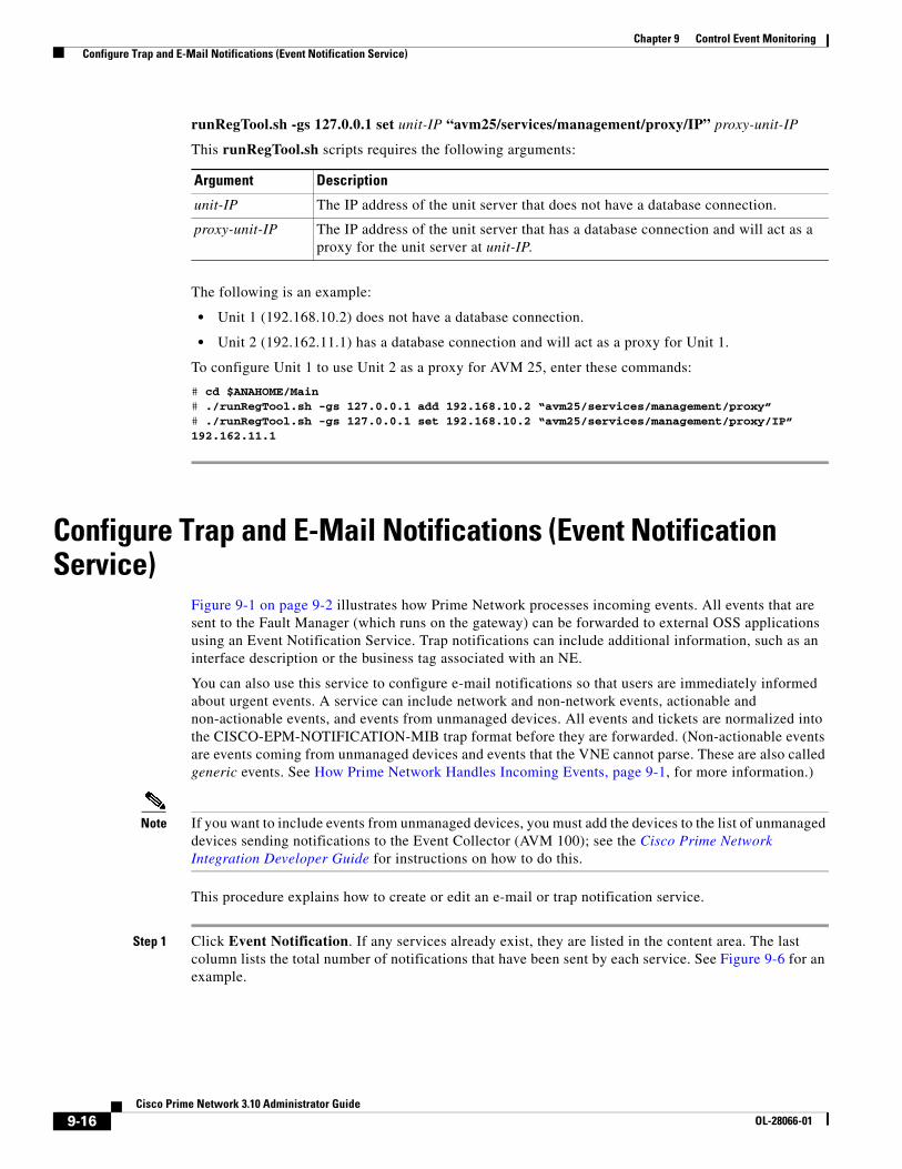
9-16Cisco Prime Network 3.10 Administrator Guide
OL-28066-01
Chapter 9 Control Event Monitoring Configure Trap and E-Mail Notifications (Event Notification Service)
runRegTool.sh -gs 127.0.0.1 set unit-IP “avm25/services/management/proxy/IP” proxy-unit-IP
This runRegTool.sh scripts requires the following arguments:
The following is an example:
• Unit 1 (192.168.10.2) does not have a database connection.
• Unit 2 (192.162.11.1) has a database connection and will act as a proxy for Unit 1.
To configure Unit 1 to use Unit 2 as a proxy for AVM 25, enter these commands:
# cd $ANAHOME/Main# ./runRegTool.sh -gs 127.0.0.1 add 192.168.10.2 “avm25/services/management/proxy”# ./runRegTool.sh -gs 127.0.0.1 set 192.168.10.2 “avm25/services/management/proxy/IP” 192.162.11.1
Configure Trap and E-Mail Notifications (Event Notification Service)
Figure 9-1 on page 9-2 illustrates how Prime Network processes incoming events. All events that are sent to the Fault Manager (which runs on the gateway) can be forwarded to external OSS applications using an Event Notification Service. Trap notifications can include additional information, such as an interface description or the business tag associated with an NE.
You can also use this service to configure e-mail notifications so that users are immediately informed about urgent events. A service can include network and non-network events, actionable and non-actionable events, and events from unmanaged devices. All events and tickets are normalized into the CISCO-EPM-NOTIFICATION-MIB trap format before they are forwarded. (Non-actionable events are events coming from unmanaged devices and events that the VNE cannot parse. These are also called generic events. See How Prime Network Handles Incoming Events, page 9-1, for more information.)
Note If you want to include events from unmanaged devices, you must add the devices to the list of unmanaged devices sending notifications to the Event Collector (AVM 100); see the Cisco Prime Network Integration Developer Guide for instructions on how to do this.
This procedure explains how to create or edit an e-mail or trap notification service.
Step 1 Click Event Notification. If any services already exist, they are listed in the content area. The last column lists the total number of notifications that have been sent by each service. See Figure 9-6 for an example.
Argument Description
unit-IP The IP address of the unit server that does not have a database connection.
proxy-unit-IP The IP address of the unit server that has a database connection and will act as a proxy for the unit server at unit-IP.

9-17Cisco Prime Network 3.10 Administrator Guide
OL-28066-01
Chapter 9 Control Event Monitoring Configure Trap and E-Mail Notifications (Event Notification Service)
Figure 9-6 Event Notification Service Window Listing Existing Services
From this window you can:
Step 2 Configure the service’s general characteristics and specify whether you want to forward the events as traps or by e-mail.
a. Enter the following basic information.
b. If you specified a trap notification service, provide the following trap information.
Create a new service Right-click Event Notification and choose New Event Notification Service
Edit an existing service Double-click the service.
Disable an existing service Right-click the service and choose Actions > Stop.
Delete a disabled service Right-click the service and choose Delete.
Field Description
Name User-defined name for the new notification service.
Description (Optional) service description.
Forward Events Forwarding method:
• As Traps—The most common method
• By E-mail—Useful when a recipient must get immediate notifications about to be informed about critical tickets and similar items. E-mails are generated every 5 seconds, and notifications within the same 5-second interval are aggregated into a single e-mail with a notification count in the subject.
Note To prevent e-mail flooding, forward only the relevant information.
Field Description
Destination IP IP address of the destination to which Prime Network will forward the received events. The gateway server must have connectivity to the destination IP address.
Port Port on the destination IP (16 2 by default).

9-18Cisco Prime Network 3.10 Administrator Guide
OL-28066-01
Chapter 9 Control Event Monitoring Configure Trap and E-Mail Notifications (Event Notification Service)
c. If you specified an e-mail notification service, provide the following e-mail information.
d. When you are done, click Next.
Step 3 Select the events and event information you want to include in (or exclude from) the trap or e-mail notification. For optimal performance, only include specific events in which you are interested (by clicking Select Types and specifying the events).
a. Specify the general categories of information you want to include in the trap or e-mail notification in the Notification Types area.
b. For Network and non-network events, specify the event types that you want to include in (or exclude from) the trap or e-mail notification.
Connection Type Transport protocol, either UDP (default) or TCP. If a TCP connection error occurs, Prime Network generates a System event.
Note Different event notification services can connect to the same destination port, but only if it uses UDP.
Community String SNMP community string used for sending the SNMP notifications (public by default).
SNMP Version SNMP version, either SNMPv1 (default) or SNMPv2.
Field Description
Field Description
Mail Server FQDN or the IP address of the e-mail server.
From Address Sender’s e-mail address.
To Address(es) Recipient’s e-mail address. Separate multiple e-mail addresses with commas or semi-colons.
Subject E-mail subject to be used for all e-mails for this service. If multiple notifications are included in an e-mail, the e-mail subject includes a notification count.
Field Adds the Following to the Notification:
Network Syslogs, Traps, and/or Service events
Non-Network System, Security, and/or Provisioning events
New Tickets Newly-created tickets
Ticket Updates Updates made to the properties in which you are interested (by clicking Select Properties and choosing the properties)
Field Description
Exclude event types from the forwarded events
Filters the events or tickets out of the trap or e-mail notification. When you choose an event, Prime Network will also exclude:
• Clearing events
• Any tickets with the specified event as its root causes

9-19Cisco Prime Network 3.10 Administrator Guide
OL-28066-01
Chapter 9 Control Event Monitoring Configure Trap and E-Mail Notifications (Event Notification Service)
Figure 9-7 Example: Event Type and Subtypes
Network Events (Network and Non-Network Events only) Select the events to include in the filter. You can select events at these levels:
• All events of the same type, such as all Syslogs, all Service events, and so forth.
• Specific events within the types, such as ACE-related syslogs, Service events related to BFDs, and so forth.
When you add events to the filter, Prime Network includes all clearing events
To specify event types for the filter:
1. Choose the category: Network and/or non-network events.
2. Choose the type, such as Syslogs, Traps, Service events, System events, and so forth.
3. To choose specific events within the types, click Select Types. This opens a dialog box that lists all of the supported event types. When you choose an event type, its subtypes are displayed in the Included Events list.
If you do not choose specific events, Prime Network will forward all events of that type. Figure 9-7 shows that when you select the link 3 down syslog (under Selected Items), Prime Network automatically includes all of its subtype events (which are listed under Included Events).
To include generic traps, select Generic trap.
Non-Network Events
Field Description

9-20Cisco Prime Network 3.10 Administrator Guide
OL-28066-01
Chapter 9 Control Event Monitoring Configure Trap and E-Mail Notifications (Event Notification Service)
c. Choose the event or ticket severities that you want to include in (or exclude from) the trap or e-mail notification and enter them in the Filter Events/Tickets by Severity area.
d. When you finish selecting the events, click Next.
Step 4 In the Source Selection dialog box, specify the source of the events to be included in (or excluded from) the service.
a. Select one of the following:
Note If you include an IP address for an unmanaged device, you must add the address to the list of unmanaged devices sending notifications to the Event Collector (AVM 100); see the Cisco Prime Network Integration Developer Guide for instructions on how to do this.
– Include all Sources—Use this to include all NEs (selected by default). You can adjust the list by specifying the devices that should be excluded (either by selecting them from the managed NEs list or entering their IP addresses). You must use this option for unmanaged NEs.
– Include all managed network elements—Use this to include all managed NEs in the service, including new NEs that are added to Prime Network. You can adjust the list by specifying the devices that should be excluded (by selecting them from the managed NEs list).
– Include specific IP address or managed network element—Use this to add a very specific list of NEs to the service. You can add them by selecting them from the managed NEs list or by entering their IP addresses.
b. When you finish specifying the sources, click Next.
Step 5 (Trap notifications only) Optionally, specify the additional data you want the notification to include by adding data to the Trap Display Options dialog box (shown in Figure 9-8). For example, you could include interface descriptions, business tags, ticket troubleshooting information, information included in the ticket, and so forth.
Field Description
Severity Include tickets/events in the notifications if they are of the chosen severity.
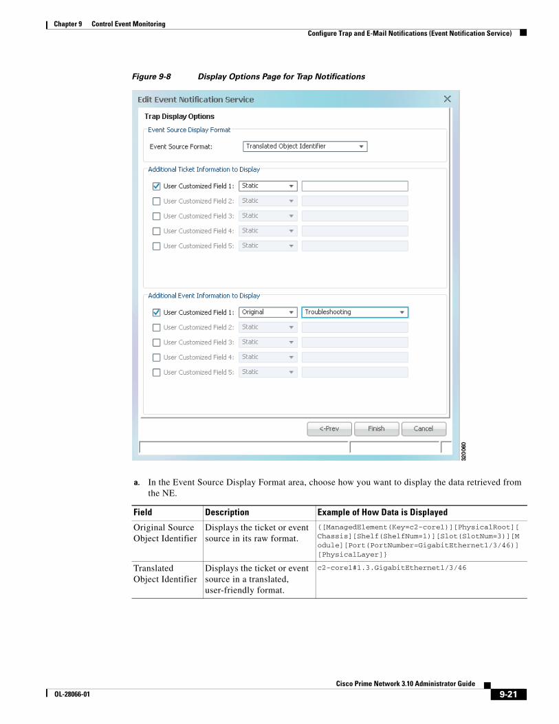
9-21Cisco Prime Network 3.10 Administrator Guide
OL-28066-01
Chapter 9 Control Event Monitoring Configure Trap and E-Mail Notifications (Event Notification Service)
Figure 9-8 Display Options Page for Trap Notifications
a. In the Event Source Display Format area, choose how you want to display the data retrieved from the NE.
Field Description Example of How Data is Displayed
Original Source Object Identifier
Displays the ticket or event source in its raw format.
{[ManagedElement(Key=c2-core1)][PhysicalRoot][Chassis][Shelf(ShelfNum=1)][Slot(SlotNum=3)][Module][Port(PortNumber=GigabitEthernet1/3/46)][PhysicalLayer]}
Translated Object Identifier
Displays the ticket or event source in a translated, user-friendly format.
c2-core1#1.3.GigabitEthernet1/3/46

9-22Cisco Prime Network 3.10 Administrator Guide
OL-28066-01
Chapter 9 Control Event Monitoring Configure System TCAs
b. In the Additional Ticket (or Event) Information to Display area, specify the data you want to add to the trap. Prime Network will populate the user customized fields in the trap with the data you specify. (For details on the exact fields that are used, see the Cisco Prime Network Integration Developer Guide.
For example, you could display the troubleshooting information for a ticket in the trap notification as shown in Figure 9-8:
– For an event or ticket, choose Static in one of the user customized fields, and enter a link or location of an Events Troubleshooting Report that you previously generated.
– (For Cisco ASR 5000 traps, and Cisco ASR 5000 traps tickets whose root cause is a trap) Choose Original > Troubleshooting and the troubleshooting information will be included in the notification.
Step 6 Click Finish to create the notification service. A status message is displayed and, if successful, the new service will appear in Prime Network Administration.
Configure System TCAsTo configure new threshold crossing alarms, use the Soft Properties feature. Soft Properties allows you to extend the supported properties for an NE, including monitoring selected properties and generating an alarm when these properties cross a user-defined threshold or violate a condition. Prime Network filters out irrelevant data, and sends only meaningful notifications.
For information on how to configure TCAs using Soft Properties, see Cisco Prime Network 3.10 Customization Guide.
Field Description
Static Adds a user-specified string to the trap. For example, you could enter Prime Network to distinguish the source of a trap.
Original Includes a raw format version of the ticket or event property you select from the drop-down list. See the example that follows this table.
Translated Includes a user-friendly version of the ticket or event property you select from the drop-down list. It is often the same as original.
NE Data Includes the source’s business tag and/or interface description (selected from a drop-down list). They are included if they meet the following criteria.
• Business tags can be included if the tag is defined on the root cause source—that is, the device (or device element) that was the source of the initial problem
• Interface descriptions can be included if the event or ticket source is an IP interface.

9-23Cisco Prime Network 3.10 Administrator Guide
OL-28066-01
Chapter 9 Control Event Monitoring Track Events
Track EventsPrime Network provides a variety of preconfigured reports that can provide you with a wide range of event information. To run any of these reports, select Reports > Run Report > Events Reports and choose the report name.
Report Name Provides the following info for a specified period:
Daily Average and Peak Highest rate of traps and syslogs received per second during a 24-hour period. Provides peaks for these periods: 1 second, 10 seconds, 1 minute, 1 hour, 1 day.
Most Common Daily Events Most common tickets, Service events, syslogs, and traps during a 24-hour period. Can be displayed as a pie chart.
Devices with Most Events By Severity
Devices with highest total events, with events grouped by severity.
Devices with Most Events by Type Devices with highest total events, with events grouped by type.
Devices with Most Syslogs Devices with highest total syslogs.
Devices with Most Traps Devices with highest total traps.
Syslog Count Total number of syslogs that occurred on specified devices.
Syslog Count by Device Total number of syslogs that occurred on specified devices, grouped by device.
Syslog Trend by Severity Total number of specified syslogs that occurred on specified devices, grouped by severity.
Event Reduction Statistics Correlation information for specified devices (number of tickets, and highest/lowest/average number of correlated events).
Mean Time to Repair Amount of time it took tickets to be cleared (manual and automatic).
Events Troubleshooting Info Troubleshooting information grouped by event.
Detailed Network Events
Detailed Non-Network Events
Detailed information about specific events that occurred on specific devices.

9-24Cisco Prime Network 3.10 Administrator Guide
OL-28066-01
Chapter 9 Control Event Monitoring Track Events
C H A P T E R
10-1Cisco Prime Network 3.10 Administrator Guide
OL-28066-01
10Manage Workflows, Command Scripts, and Activations
These topics describe administrative tasks for managing workflows, activations, and command scripts using the Administration:
• How Are Workflows, Activations, and Command Scripts Related?, page 10-1
• Get Information About Executed Workflows and Activations, page 10-2
• Add Credential Validation to Activations and Command Scripts, page 10-6
• Add Warning Message to Activations and Command Scripts, page 10-6
• Manage Workflow and Activation Templates, page 10-4
• Abort and Delete Executed Workflows and Activations, page 10-6
• Track Workflow, Activation, and Command-Related Events, page 10-7
How Are Workflows, Activations, and Command Scripts Related?
Note If Prime Network is installed with Cisco Prime Central, you can launch the Workflow GUI client by selecting Tools > Workflow in the Prime Network Vision GUI client.
Command scripts are used to make physical and logical configuration changes on a network element. The changes are made by executing a programmable sequence of SNMP or Telnet command lines. Command scripts are usually created using the Command Builder GUI client. If the command script is used in an activation, it is sometimes called an activation script.
A workflow is a series of command scripts that are grouped together in sequences and branches. Workflows are created using the Workflow Editor GUI client, saved as a templates, tested, and finally saved on the gateway. Once they are available on the gateway, users with OperatorPlus privileges can run the workflow using a BQL command, creating a workflow instance.
Activations are workflows that configure services on devices. Like workflows, activations are created using the Workflow Editor GUI client, saved as templates, tested, and used in wizards. (Activation wizards are created using the Activation Wizard builder.). Once an activation wizard is saved on the gateway, users that have sufficient privileges can run the actions by choosing them from the Activation main menu (in the Vision GUI client). This creates an activation instance.

10-2Cisco Prime Network 3.10 Administrator Guide
OL-28066-01
Chapter 10 Manage Workflows, Command Scripts, and Activations Get Information About Executed Workflows and Activations
When a user executes a workflow template—whether it be a workflow template run using BQL, or an activation template using the Activation menu—Prime Network creates a new workflow or activation instance with its own unique ID, and stores it in the database. Thus there can be many instantiations of a single workflow template or a single activation template. Each instance has its own output, which can be exported and analyzed.
All workflow and activation templates that have been uploaded to the gateway are visible in the Administration GUI client. Any time a user executes a workflow or activation, Prime Network generates a Provisioning event, and the workflow or activation instance status and properties are displayed in the Administration GUI client.
The Workflow Engine runs on AVM 66. To deploy, retrieve, or delete a workflow or activation template from the gateway, AVM 66 must be running.
Workflow and activation instances are saved for seven days and are then purged from Prime Network by the integrity service. Templates and workflows are saved in the database under the pnuser_dwe schema.
Get Information About Executed Workflows and Activations
Note If Prime Network is installed with Cisco Prime Central, you can launch the Workflow GUI client by selecting Tools > Workflow in the Prime Network Vision GUI client.
When you select Workflow Engine > Workflows, Prime Network lists all workflow and activation instances—that is, executed workflows and activations—from the past 7 days. From here you can view their properties and output. Figure 10-1 shows an example of the Prime Network Administration window with Workflows selected.
Figure 10-1 Workflows Window
The total number of workflow and activation instances in the Prime Network system is listed at the top left of the window. This counter that is updated whenever a workflow or activation is deleted or added to the system.
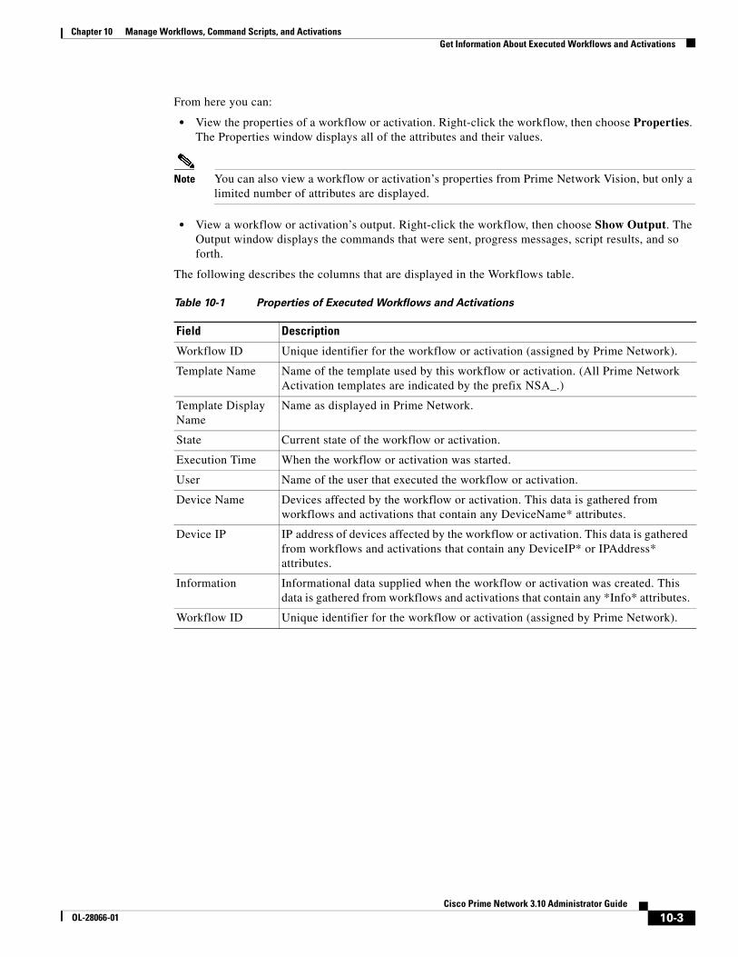
10-3Cisco Prime Network 3.10 Administrator Guide
OL-28066-01
Chapter 10 Manage Workflows, Command Scripts, and Activations Get Information About Executed Workflows and Activations
From here you can:
• View the properties of a workflow or activation. Right-click the workflow, then choose Properties. The Properties window displays all of the attributes and their values.
Note You can also view a workflow or activation’s properties from Prime Network Vision, but only a limited number of attributes are displayed.
• View a workflow or activation’s output. Right-click the workflow, then choose Show Output. The Output window displays the commands that were sent, progress messages, script results, and so forth.
The following describes the columns that are displayed in the Workflows table.
Table 10-1 Properties of Executed Workflows and Activations
Field Description
Workflow ID Unique identifier for the workflow or activation (assigned by Prime Network).
Template Name Name of the template used by this workflow or activation. (All Prime Network Activation templates are indicated by the prefix NSA_.)
Template Display Name
Name as displayed in Prime Network.
State Current state of the workflow or activation.
Execution Time When the workflow or activation was started.
User Name of the user that executed the workflow or activation.
Device Name Devices affected by the workflow or activation. This data is gathered from workflows and activations that contain any DeviceName* attributes.
Device IP IP address of devices affected by the workflow or activation. This data is gathered from workflows and activations that contain any DeviceIP* or IPAddress* attributes.
Information Informational data supplied when the workflow or activation was created. This data is gathered from workflows and activations that contain any *Info* attributes.
Workflow ID Unique identifier for the workflow or activation (assigned by Prime Network).

10-4Cisco Prime Network 3.10 Administrator Guide
OL-28066-01
Chapter 10 Manage Workflows, Command Scripts, and Activations Manage Workflow and Activation Templates
Manage Workflow and Activation Templates
Note If Prime Network is installed with Cisco Prime Central, you can launch the Workflow GUI client by selecting Tools > Workflow in the Prime Network Vision GUI client.
When you select Workflow Engine > Templates, Prime Network lists all activation and workflow templates that have been saved on the gateway, as shown in Figure 10-2. From here you can do the following:
• View template properties by right-clicking a template and choosing Properties.
• Delete a template by right-clicking a template and choosing Delete. Templates. Note that while workflow and activation instances are deleted on a regular basis, workflow and activation templates are not. They can only be deleted manually or by using BQL.
Figure 10-2 Workflow Templates Window
Find a Workflow or ActivationPrime Network can easily contain thousands of workflow and activation instances. To help you locate specific ones, the Workflow window contains a robust search tool. This procedure explains how to use the search tool.
Step 1 Choose Workflow Engine > Workflows to display the search tool.
Step 2 In the Execution Time area, enter the time period you want to search. By default the current day is selected. (This is a required field.)

10-5Cisco Prime Network 3.10 Administrator Guide
OL-28066-01
Chapter 10 Manage Workflows, Command Scripts, and Activations Manage Workflow and Activation Templates
Step 3 In the Match area, enter the criteria you want to the search to match.
Note If you want to search by date only, choose None from the Match drop-down list.
a. Select the Match operator (none, any all).
b. Create a rule by selecting an attribute, operator, and value. The operators and values that are displayed depend on the attribute you select. Values are case-insensitive; wild cards are not supported.
Step 4 Click Search to display the results. See Table 10-1 on page 10-3 for an explanation of the fields.
Note If performance is poor, consider adjusting the maximum number of instances returned in a search result (the default is 5,000 workflows). See Adjust the Performance of Workflow Searches, page 10-5.
If any fields are empty (such as an IP address), either the attribute was not included in the workflow or activation (and thus is not in the database), or the search criteria was not entered correctly.
Adjust the Performance of Workflow Searches
By default, the maximum number of search results displayed is 5,000. You can adjust this to a lower number to get faster results.
Note Do not adjust the value to more than 5,000. Doing so could can negatively impact the performance of the search tool.
Step 1 Log into the gateway server as pnuser and change to the Main directory:
# cd $ANAHOME/Main
Step 2 Enter the following command to adjust the total search results that are displayed by the GUI client:
runRegTool.sh -gs gw-IP set unit-IP "site/cvm/management/workflow/searchResultMaxRawSize" value
This example changes the maximum results 1,000 workflows:
# runRegTool.sh -gs 127.0.0.1 set 0.0.0.0 "site/cvm/management/workflow/searchResultMaxRawSize" 1000
The change is applied to all GUI clients that connect to the gateway. For open clients, close and reopen them to apply the change. For information on the format of the runRegTool command, see Changing Registry Settings Using runRegTool.sh, page C-2.

10-6Cisco Prime Network 3.10 Administrator Guide
OL-28066-01
Chapter 10 Manage Workflows, Command Scripts, and Activations Add Credential Validation to Activations and Command Scripts
Add Credential Validation to Activations and Command ScriptsBy default, users must have the following privileges to run workflows, activations, or command scripts:
• OperatorPlus privileges are required for workflows
• Configurator privileges are required for activations and command scripts
You can configure Prime Network so that it prompts users for their device credentials when they execute activations or command scripts. When this global setting is enabled, Provisioning and Audit events will include the device user name. Once the credentials are entered, they are used through the GUI client session and do not have to be re-entered. For activations, users must have the same credentials for all devices involved in the activation because Prime Network propagates the credentials to all command scripts in the activation. (Scheduled commands will continue to use the VNE's credentials.) This feature, controlled from Global Settings > Security Settings > User Account Settings, is disabled by default. To enable it, see User Permissions: Lockouts, Commands and Activations, and Job Scheduling, page 7-6.
Add Warning Message to Activations and Command ScriptsIf desired, you can configure Prime Network to display a warning message whenever a user executes a command script or an activation. Users must acknowledge the message before proceeding. Figure 10-3 provides an example.
Figure 10-3 User Message When Running Command Scripts or Activations
When you enable this mechanism, you can also change the message. This feature is disabled by default. To enable it, choose Global Settings > Commands and Activations, enable the feature, and enter the message text you want Prime Network to display.
Abort and Delete Executed Workflows and Activations
Note If Prime Network is installed with Cisco Prime Central, you can launch the Workflow GUI client by selecting Tools > Workflow in the Prime Network Vision GUI client.
You can abort or delete an executed workflow or activation from Workflows window (see Figure 10-1 on page 10-2) by right-clicking the workflow or activation, and choosing Abort or Delete.
A delete operation permanently removes the workflow or activation instance from the database.

10-7Cisco Prime Network 3.10 Administrator Guide
OL-28066-01
Chapter 10 Manage Workflows, Command Scripts, and Activations Track Workflow, Activation, and Command-Related Events
An abort operation initiates a rollback. A rollback has the following characteristics:
• Rolls back the workflow and activation tasks in reverse order of execution.
• Ignores workflow or activation tasks if the task’s RollbackEnabled attribute (in Command Builder) is set to false. (This is useful for a BQL task executing a script that does not have an appropriate rollback, or a BQL task executing a gateway command (because gateway commands do not support rollback).
• Performs the actions defined in the rollback section of the command or script (in Command Builder).
A workflow instance is automatically aborted if any of its tasks are aborted.
Track Workflow, Activation, and Command-Related EventsThe following predefined reports can provide you with important database statistics for a period of time that you specify. To run any of these reports, select Reports > Run Report > Events Reports > Detailed Non-Network Events and choose the report name.
Report Name Provides the following information:
Detailed Audit Events Which users invoked command scripts, workflows, and activations (each instance is a separate event)
Detailed Provisioning Events
All command scripts, workflows, and activations that users have executed (each instance is a separate event)

10-8Cisco Prime Network 3.10 Administrator Guide
OL-28066-01
Chapter 10 Manage Workflows, Command Scripts, and Activations Track Workflow, Activation, and Command-Related Events

C H A P T E R
11-1Cisco Prime Network 3.10 Administrator Guide
OL-28066-01
11System Security
These topics provide an overview of the communication and data security mechanism used by Prime Network:
• Communication Security Between Prime Network Components, page 11-1
• Communication Security with Devices: SSH and SNMPv3, page 11-5
• Registry Security, page 11-7
• System Passwords (Database, Graphs Tool, root, bos* Users), page 11-8
• Create a GUI Client Banner Message, page 11-12
Communication Security Between Prime Network ComponentsFigure 11-1 illustrates the different forms of secure communication that are implemented between the Prime Network gateway server, units, clients, and database.

11-2Cisco Prime Network 3.10 Administrator Guide
OL-28066-01
Chapter 11 System Security Communication Security Between Prime Network Components
Figure 11-1 Communication Security in Prime Network
A socket factory service that runs on the gateway server implements SSL sockets between:
• The gateway and all units
• The gateway and all clients
With SSL version 3.0, keys are created when you install Prime Network on the gateway server. All secured connections use the same private key and certificate for SSL authentication. After installation, these keys are distributed by the gateway to the clients and other units. SSL keys can be recreated (as described in the Cisco Prime Network Integration Developer Guide).
Whenever a socket cannot be opened, a System event is generated and is displayed in Prime Network Events.
Figure 11-2 provides a simplified illustration of the methods and protocols that Change and Configuration Management, and devices use to communicate with each other.
Caution FTP is not a secure mode of transfer. Use SCP/SFTP instead, for secure config and image transfers. You should also configure a special FTP user for file transfers. For information on how to do this, see the Change and Configuration Management information in the Cisco Prime Network 3.10 User Guide.
HTTP
2834
93
GUI Client
OracleDB
AVM(s)Internal
administrationscript(s)
Gateway Server
AVM(s)
Unit Server(s)
BQL Client
Point to PointCommunication
(SSL)
DatabaseCommunication
(JDBC)
TransportCommunication(SSL)SSH
(open portson unit server)

11-3Cisco Prime Network 3.10 Administrator Guide
OL-28066-01
Chapter 11 System Security Communication Security Between Prime Network Components
Figure 11-2 Communication Security in Change and Configuration Management
Gateway Server and Unit Communication Security
Communication between the gateway server and units is called transport communication. Transport connections are encrypted when the unit and gateway are on different machines, but are not encrypted when both are local to the same machine. Similarly, AVMs use transport communication, and communication between AVMs is encrypted when the AVMs are on different machines. There is no option to change this behavior in the GUI clients.
Prime Network uses the SSH protocol for administrative messages (such as scp) between the gateway and units. A random certificate (that is privately signed) is generated on the gateway at installation time. When Prime Network is installed on any unit (or the unit is restarted), the keys are copied from the gateway to the unit.
Gateway Server and Client (Including BQL) Communication Security
For gateway and client communication, Prime Network uses a proprietary protocol called PTP (Point to Point communication). This is encrypted using SSL. The SSL keys are downloaded to Prime Network clients using the JNLP (Webstart) protocol.
For BQL clients, the gateway server allows secured and unsecured connections from local clients (on port 9002), but only secured connections from clients on other machines. By default, port 9002 only allows unsecured connections. Information on how to change this behavior is described in the BQL documentation in the Cisco Prime Network Integration Developer Guide.
For a client to communicate with the Prime Network gateway using Perl, a certificate in .pem format is required. This can be generated from the .cer format using the two-stage process described in the Cisco Prime Network Integration Developer Guide.
Change and ConfigurationManagement Web Client
HTTP/HTTPS
Change and Configuration Management (AVM 77)
AVM 11
Gateway Server
AVMs
Unit Server(s)
SCP/SFTPFTP/TFTP
BQL
3450
98
Devices
SCP

11-4Cisco Prime Network 3.10 Administrator Guide
OL-28066-01
Chapter 11 System Security Communication Security Between Prime Network Components
If a client trusts all servers, the public key is automatically imported as part of the SSL handshake. However, for a client to validate a server's public key, the .truststore file must be manually copied from the server.
For more information on SSL sockets and BQL, such as the architecture and negotiation process, see the Cisco Prime Network Integration Developer Guide.
Database Connections
Prime Network is connected to the database using an Oracle encryption feature. All client-to-database connections are encrypted. Server-to-database connections are encrypted if are using an embedded database; otherwise, they are not.
If you have an external database and want to enable encryption on server-to-database connections, follow this procedure. You must run it for each database schema. The schemas are listed below.
Before You Begin
Make sure the values you set comply with the values set on the server side (the database server).
Step 1 Log into the gateway as pnuser and change to the Main directory.
# cd $ANAHOME/Main
Step 2 Run the following command to specify the conditions required to establish a connection:
runRegTool.sh -gs localhost set 0.0.0.0 site/persistency/nodes/db_schema/EncryptionClient value
The Encryption Client value can be one of the following settings:
Step 3 Run the following command to specify the encryption algorithm the connection should use:
runRegTool.sh -gs localhost set 0.0.0.0 site/persistency/nodes/db_schema/EncryptionTypesClient value
Table 11-1 Database Schema Entries for runRegTool.sh
db_schema Description Example
pnuser Fault Database pn310
ep Event Archive (event persistence and archiving) pn310_ep
dwe Workflow Engine pn310_dwe
xmp Change and Configuration Management pn310_xmp
admin Database maintenance pn310_admin
rep Reports data based on main schema pn310_rep
ep_rep Reports data based on Event Archive schema pn310_ep_rep
value Description
rejected Do not enable the security service, even if it is required by the other side.
accepted Enable the security service if it is required or requested by the other side.
requested Enable the security service if it is permitted by the other side.
required Security service must be enabled; otherwise the connection is prevented.

11-5Cisco Prime Network 3.10 Administrator Guide
OL-28066-01
Chapter 11 System Security Communication Security with Devices: SSH and SNMPv3
The EncryptionTypesClient value can be one or more of the following algorithms (comma-separated):
Step 4 Restart the gateway server.
For more information on the database schemas, see Overview of the Prime Network Database and Schemas, page 8-1.
Gateway and Unit Servers Behind Firewalls or NAT Devices
If any unit servers are located behind firewalls or NAT devices:
• The unit is displayed in Prime Network Administration GUI client with an IP address of 0.0.0.#. This is an artificial IP address used by the gateway server.
• You do not have to open special ports for the units. The units will always initiate communications.
• An Event Collector (AVM 100) must be running on at least one of the units behind the firewall. If you have several NAT sites with similar configuration, an Event Collector must be running on at least one unit at each site.
If a gateway server is behind a firewall, you must open ports on the firewall. The gateway will to need publicly addressable IP address.
Managed Devices Behind Firewalls or NAT Devices
If there is a firewall between a GUI client and a managed device, all attempted Telnet connections to the device will fail. The Prime Network Administration GUI client provides a device proxy feature that, when enabled, routes connections from the client through the gateway server and units, as required, to reach the device. Supported connections are Telnet, Ping, and SSH. When it is enabled, dedicated SSH connections are used between the gateway and the unit. For information on how to configure this feature, see Manage Configurations with Firewalls (Device Proxy), page 3-23.
Communication Security with Devices: SSH and SNMPv3In Prime Network, protocol collectors are the components responsible for actively polling devices and transporting information between devices and the Prime Network gateway. Protocols collectors are part of the instrumentation layer of Prime Network VNEs. A device has a collector for each protocol it supports, such as one collector for SSH and another collector for SNMP. Each collector contains the necessary logic for its specific protocol.
The security of device communication is maintained by specifying SSH and SNMPv3 authentication and encryption methods when you create the VNE. Table 11-2 summarizes the security methods that are supported by each protocol.
value Description
RC4_128,RC4_40,RC4_56,RC4_256 Arcfour
AES256,AES192,AES128 Advanced Encryption Standard (AES)
3DES168,3DES112 Data Encryption Standard (DES)

11-6Cisco Prime Network 3.10 Administrator Guide
OL-28066-01
Chapter 11 System Security Communication Security with Devices: SSH and SNMPv3
The settings in Table 11-2 can be controlled from Prime Network Administration, as described in VNE Properties: Telnet/SSH, page D-6. The exceptions are the SSHv2 key exchange algorithm, MAC algorithms, ciphers, and host key algorithms, which you can only change by editing the registry. By default, all of the SSHv2 algorithm settings in Table 11-2 are supported.
Note All changes to the registry should only be carried out with the support of Cisco. For details, contact your Cisco account representative. Manually editing the SSHv2 connection properties can cause the connection between the VNE (client) and device (server) to fail. Change these settings only if you are familiar with their functionality.
Table 11-2 Device Communication Security Features in SSHv1, SSHv2, and SNMPv3
Protocol Supported Security Feature for Device Communication
SSHv1 Encryption ciphers: DES, 3DES, Blowfish
SSHv2 Client Authentication: password, public keys
Server Authentication Method: none, save-first-auth, preconfigured
Server Authentication Key: fingerprint or public key (not used if none is chosen for server authentication method)
Key exchange: DH-group1-sha1, DH-group1-exchange-sha1
MAC algorithm: SHA1, MD5, SHA1-96, MD5-96
Ciphers: 3DES, AES-128, AES-192, AES-256, Blowfish, Arcfour
Host Key Algorithm: DSA, RSA
SNMPv3 Authentication settings: NoAuthPriv (authentication without encryption), AuthPriv (authentication and encryption)
Ciphers: DES, AES128, AES192, AES256
Encryption algorithms: MD5, SHA
Note The use of SNMP V3 with AES192 or AES256 might be subject to import restrictions on cryptography key strength in some countries. Therefore, if you want to use these combinations, please open a TAC case.
Table 11-3 Registry Settings for SSHv2 Communication Between Device and VNE
Registry Entry Description Default Value
mac-alg Allow MAC algorithms sha1,md5,sha1-96,md5-96,
keys-exchange-alg Allow Key exchange algorithms diffie-hellman-group1-sha1,diffie-hellman-group1-exchange-sha1,
host-key-alg Allowed host key algorithms dsa,rsa,
encryption-alg Permitted encryption (ciphers) algorithms
3des,aes-128,aes-192,aes-256,blowfish,arcfour

11-7Cisco Prime Network 3.10 Administrator Guide
OL-28066-01
Chapter 11 System Security Registry Security
The following procedure shows how to check and change your current settings.
Step 1 Log into the gateway as pnuser (where pnuser is the operating system account for the Prime Network application, created when Prime Network is installed; for example, pn310), and change to the Main directory by entering the following command:
# cd $ANAHOME/Main
Step 2 Issue the following command to check the current default SSHv2 security settings for VNE and device communication:
# ./runRegTool.sh -gs 127.0.0.1 get 127.0.0.1 "agentdefaults/da/ip_default/protocols/telnet/connection/algorithms"<key name="algorithms"> <entry name="mac-alg">sha1,md5,sha1-96,md5-96,</entry> <entry name="keys-exchange-alg">diffie-hellman-group1-sha1,diffie-hellman-group1-exchange-sha1,</entry> <entry name="host-key-alg">dsa,rsa,</entry> <entry name="encryption-alg">3des,aes-128,aes-192,aes-256,</entry></key>
For example, the following command overwrites the encryption (ciphers) algorithms so that 3DES is no longer allowed for any newly-created VNEs:
Note Each algorithm type should have at least one algorithm entry (supported algorithm).
# ./runRegTool.sh -gs 127.0.0.1 set 0.0.0.0 "site/agentdefaults/da/ip_default/protocols/telnet/connection/algorithms/encryption-alg" “aes-128,aes-192,aes-256,”
Step 3 Restart the AVM.
Registry SecurityThe Golden Source registry is the master registry responsible for maintaining, distributing, and updating registry configuration files to all Prime Network units and the Prime Network gateway. The master copy of the Golden Source files is centrally located on the gateway server at:
NETWORKHOME/Main/registry/ConfigurationFiles
Credentials data is encrypted. This includes the SNMP, Telnet, and SSH credentials for VNEs, and the database password. Sections that are encrypted are marked with an ENCRYPTED_ENTRY_AES prefix.

11-8Cisco Prime Network 3.10 Administrator Guide
OL-28066-01
Chapter 11 System Security System Passwords (Database, Graphs Tool, root, bos* Users)
System Passwords (Database, Graphs Tool, root, bos* Users)These topics explain how to change system-level passwords:
• Change Password for bosenable, bosconfig, and bosusermanager, and root, page 11-8
• Change Password for Database Schemas, page 11-9
• Change Password for Diagnostics (Graphs) Tool, page 11-12
For information on managing individual user passwords, see Manage User Accounts, page 7-1.
Change Password for bosenable, bosconfig, and bosusermanager, and rootThe passwords for bosenable, bosconfig, bosusermanager, and root are established during the Prime Network installation. Use the following to change the bos passwords.
To change the root password, you can use Change GUI Client User Passwords, page 7-8. If you have lost the root password, you can use this procedure to reset it.
Step 1 Using an SSH session, log in to the Prime Network gateway as pnuser and change to the Main directory:
# cd $ANAHOME/Main
Step 2 Encrypt the new password in Prime Network using the following command:
java -classpath ./jars/classes.jar com.sheer.metromission.authentication2.PasswordEncrypt password
The encrypted password is listed in the command output (after the comma). You will need this information in Step 3.
For example, the following command creates a new password for test.
# java -classpath ./jars/classes.jar com.sheer.metromission.authentication2.PasswordEncrypt test
The command returns the following output. The portion of the output that is in bold is what you will need in the subsequent step.
'test' -> 'PEv1:DC57A2A7', '7E84D3A8F60F30B7B62946D532E24608'
Step 3 Log in to the Oracle database and change the password for bosenable, bosconfig, bosusermanager, and root in the database.
a. Log in to the Oracle database as pnuser. In the following example, pnuser is pn310 and the pnuser password is admin.
sqplplus pn310/admin
b. Change the password using the following command, where xxx is the second string of output from Step 2, and user is bosenable, bosconfig, bosusermanager or root. In this example, the bosenable password is being changed:
update bosuser set ENCRYPTEDPASSWORD='xxx' where username='bosenable';
For example:
SQL> update bosuser set ENCRYPTEDPASSWORD='7E84D3A8F60F30B7B62946D532E24608' where username='bosenable'; 1 row updated.

11-9Cisco Prime Network 3.10 Administrator Guide
OL-28066-01
Chapter 11 System Security System Passwords (Database, Graphs Tool, root, bos* Users)
To update the root user password, you would use the following command:
update bosuser set ENCRYPTEDPASSWORD='xxx' where username='root';
c. Commit the change:
SQL> commit;Commit complete.
d. Repeat Step b and Step c for bosconfig and bosusermanager.
Change Password for Database SchemasBy default, an operating system account for the Prime Network application is created when Prime Network is installed. When the database is created, it uses this operating system account name as the basis for naming the schemas. The following are the database schemas that are created by Prime Network. As an example, in the following table the Prime Network operating system account (pnuser) is named pn310. (For more details about these schemas, see Overview of the Prime Network Database and Schemas, page 8-1.)
At installation time, the network-conf script assigns the same password to all of the schemas. After installation, you can assign different passwords to each schema. The following procedure describes how to change any or all of the passwords. Note that you have to change the password in two places: in the Oracle software and in the Prime Network software.
In the following procedure, pnuser-DB, pnuser-EP-DB, pnuser-DWE-DB, pnuser-admin-DB, and pnuser-XMP-DB are the user accounts for the four database schemas.
Step 1 Log into the Prime Network gateway server as pnuser.
Step 2 To change the pnuser-DB password (for the general data):
a. Enter the following sqlplus command to change the pnuser-DB password in the Oracle software:
# sqlplus /nolog \@$ANAHOME/Main/unix/setPassword.sql DBA-username DBA-password pnuser-DB pnuser-DB-new-password DB-IP DB-port SID
Schema Name Description Example
pnuser Prime Network general data pn310
pnuser_ep Prime Network Event Archive (event persistence and archiving data)
pn310_ep
pnuser_dwe Prime Network Workflow Engine data pn310_dwe
pnuser_xmp Prime Network Change and Configuration Management data
pn310_xmp
pnuser_admin Prime Network maintenance and administration data pn310_admin
pnuser_rep Prime Network reports data based on main schema pn310_rep
pnuser_ep_rep Prime Network reports data based on Event Archive schema
pn310_ep_rep

11-10Cisco Prime Network 3.10 Administrator Guide
OL-28066-01
Chapter 11 System Security System Passwords (Database, Graphs Tool, root, bos* Users)
For example:
# sqlplus /nolog \@$ANAHOME/Main/unix/setPassword.sql system systempassword pn310 pn310newDBpassword 127.0.0.1 1521 MCDB
b. Enter the following to change the pnuser-DB password in the Prime Network software (the gateway server must be up and running):
# cd $ANAHOME/Main# ./runRegTool.sh -gs 127.0.0.1 setEncrypted 0.0.0.0 “site/persistency/nodes/main/PASS” pnuser-DB-new-password
Step 3 To change the pnuser-EP-DB password (for the event persistence and archiving data):
a. Enter the following sqlplus command to change the pnuser-EP-DB password in the Oracle software:
# sqlplus /nolog \@$ANAHOME/Main/unix/setPassword.sql DBA-username DBA-password pnuser-EP-DB pnuser-EP-DB-new-password DB-IP DB-port SID
For example:
# sqlplus /nolog \@$ANAHOME/Main/unix/setPassword.sql system systempassword pn310_ep EPnewDBpassword 127.0.0.1 1521 MCDB
b. Enter the following to change the pnuser-EP-DB password in the Prime Network software (the gateway server must be up and running):
# cd $ANAHOME/Main# ./runRegTool.sh -gs 127.0.0.1 setEncrypted 0.0.0.0 “site/persistency/nodes/ep/PASS” pnuser-EP-DB-new-password
Step 4 To change the pnuser-DWE-DB password (for the Workflow Engine data):
a. Enter the following sqlplus command to change the pnuser-DWE-DB password in the Oracle software:
# sqlplus /nolog \@$ANAHOME/Main/unix/setPassword.sql DBA-username DBA-password pnuser-DWE-DB pnuser-DWE-DB-new-password DB-IP DB-port SID
For example:
# sqlplus /nolog \@$ANAHOME/Main/unix/setPassword.sql system systempassword pn310_dwe DWEnewDBpassword 127.0.0.1 1521 MCDB
b. Enter the following to change the pnuser-DWE-DB password in the Prime Network software (the gateway server must be up and running):
# cd $ANAHOME/Main# ./runRegTool.sh -gs 127.0.0.1 setEncrypted 127.0.0.1 avm66/services/workflow/engine/databasePassword pnuser-DWE-DB-new-password
Step 5 To change the pnuser-admin-DB password (for administration and maintenance data):
a. Enter the following sqlplus command to change the pnuser-admin-DB password in the Oracle software:
# sqlplus /nolog \@$ANAHOME/Main/unix/setPassword.sql DBA-username DBA-password pnuser-admin-DB pnuser-admin-DB-new-password DB-IP DB-port SID
For example:
# sqlplus /nolog \@$ANAHOME/Main/unix/setPassword.sql system systempassword pn310_admin adminnewDBpassword 127.0.0.1 1521 MCDB

11-11Cisco Prime Network 3.10 Administrator Guide
OL-28066-01
Chapter 11 System Security System Passwords (Database, Graphs Tool, root, bos* Users)
b. Enter the following to change the pnuser-admin-DB password in the Prime Network software (the gateway server must be up and running):
# cd $ANAHOME/Main# ./runRegTool.sh -gs 127.0.0.1 setEncrypted 0.0.0.0 “site/persistency/nodes/admin/PASS” pnuser-admin-DB-new-password
Step 6 To change the pnuser-XMP-DB password (for Change and Configuration Management):
Note The password should not contain ampersand (@) or forward slash (/) characters. If you enter either of these special characters, future installations will fail.
a. Enter the following sqlplus command to change the pnuser-XMP-DB password in the Oracle software:
# sqlplus /nolog \@$ANAHOME/Main/unix/setPassword.sql DBA-username DBA-password pnuser-XMP-DB pnuser-XMP-DB-new-password DB-IP DB-port SID
For example:
# sqlplus /nolog \@$ANAHOME/Main/unix/setPassword.sql system systempassword pn310_xmp pn310XMPnewDBpassword 127.0.0.1 1521 MCDB
b. Enter the following to change the pnuser-XMP-DB password in the Prime Network software:
# cd $XMP_HOME/bin# xmpchangepw.ksh pnuser-XMP-DB-old-password pnuser-XMP-DB-new-password
Step 7 Stop the gateway server and units:
# cd $ANAHOME/Main# networkctl stop
Step 8 Run the unlock command to ensure that the Prime Network Oracle accounts are not locked. A lock can happen if Prime Network accesses the database (which it does constantly) between the time when you run the sqlplus setpassword.sql command and the time when you run the runRegTool.sh or xmpchangepw.ksh scripts. In that period of time, the passwords are not in sync.
a. As the Oracle UNIX user, log in to sqlplus:
# sqlplus /nologSQL> connect /as sysdba
b. Run the unlock command. You need only run the unlock command on accounts that were changed—in other words, in the following command, account-name can be pnuser, pnuser-EP-DB, pnuser-DWE-DB, or pnuser-XMP-DB from the previous steps.
SQL> alter user account-name account unlock
Step 9 Start the gateway server and units:
# cd $ANAHOME/Main# networkctl start

11-12Cisco Prime Network 3.10 Administrator Guide
OL-28066-01
Chapter 11 System Security Create a GUI Client Banner Message
Change Password for Diagnostics (Graphs) ToolThe username and password for the Diagnostics Tool (described in Prevent System Overloads (Advanced Overload Prevention/Safe Mode), page 8-23) is established during the Prime Network installation.
To change the passwords:
Step 1 Using an SSH session, log in to the Prime Network gateway as pnuser and change to the Main directory:
# cd $ANAHOME
Step 2 Change the username and password for the Diagnostics tool using the following command, where operating-system is either linux or solaris, depending on your configuration:
# utils/operating-system/apache/bin/htpasswd ./Main/webroot/.passwd new-username
The utility will prompt you for a new password for new-username.
Create a GUI Client Banner MessagePrime Network Administration enables you to define a Message of the Day, or banner, that is displayed when a user logs into any client application. The user must accept the message before logging in. If the user does not accept the message, the user cannot log in. The message supports HTML format. Figure 11-3 provides an example.
Figure 11-3 Message of the Day Example
The message can be changed as required. However, only one message is applied at a time.
11-13Cisco Prime Network 3.10 Administrator Guide
OL-28066-01
Chapter 11 System Security Create a GUI Client Banner Message
To create a message of the day:
Step 1 Choose Global Settings > Message of the Day. The Title and Message fields appear in the content area.
Step 2 In the Title field, enter a title for the message.
Step 3 In the Message field, enter the text that is to appear when users log in.
Note Abort and Continue buttons are displayed in the message dialog box by default, so the message must be related to these actions. For example, “Do you accept the terms of use in the Product License Agreement? Click Continue to proceed or click Abort to cancel.”
Step 4 Click Save. A confirmation message is displayed.
Step 5 Click OK. The message is displayed when a user logs into any client application.
To delete a message of the day, edit the message so that the Title and Message field is empty, and click Save.

11-14Cisco Prime Network 3.10 Administrator Guide
OL-28066-01
Chapter 11 System Security Create a GUI Client Banner Message

C H A P T E R
12-1Cisco Prime Network 3.10 Administrator Guide
OL-28066-01
12Perform Advanced VNE Configurations
These topics provide advanced technical information about VNEs, including the configurable points:
• Change VNE Polling Settings, page 12-1
• Change Settings That Determine Device Reachability, page 12-23
• Change How VNE Commands Are Executed (Collectors Command and Priorities), page 12-31
• Change Settings That Control VNE Data Saved After Restarts, page 12-36
• Create Connections for Unmanaged Network Segments (Cloud VNEs and Links), page 12-42
• Track VNE-Related Events, page 12-54
Change VNE Polling SettingsPrime Network uses a variety of polling methods to monitor the network.Working together these mechanisms maintain the balance between ensuring model fidelity (more polling cycles) while protecting system performance (less polling cycles). Table 12-1 lists the polling methods used by Prime Network, their default behavior, and where you can find more information on each method.
Note Reduced polling is enabled on all devices by default. If the device type does not support reduced polling, it uses regular polling.
If you are experiencing high CPU usage, see CPU Utilization Problems: Where to Begin, page 12-2.

12-2Cisco Prime Network 3.10 Administrator Guide
OL-28066-01
Chapter 12 Perform Advanced VNE Configurations Change VNE Polling Settings
CPU Utilization Problems: Where to BeginIf you suspect ongoing CPU utilization problems, start with these troubleshooting steps:
1. Review the device log files to find any recurring polling spikes that extend for prolonged periods. If the CPU spikes are not occurring at a constant interval, it is likely a network events rather than a device problem.
2. Verify whether other applications (besides Prime Network) are managing the devices, and check those applications for problems before proceeding with Prime Network changes.
3. If you think the problem resides in Prime Network, analyze the CPU over a 24-hour period as follows:
– Log onto the device and check the usage for different timelines. (Refer to the operating system documentation that applies to the device type.)
– Check the audit log for any open sessions that correspond with the usage problems.
4. Read the following topics:
– Adaptive Polling, page 12-10
– Regular Polling (VNE Polling Groups), page 12-17
5. Consider disabling MAC-based topology. To disable this topology, use the following registry command, where devicetype is the registry location for the device type.
Table 12-1 Polling Mechanisms Used by Prime Network
Polling Mechanism Description Default Setting For information, see:
Reduced polling
Polls the device when a configuration change syslog is received, rather than according to any interval. Changes to the model are updated immediately.
Enabled for all VNEs (but not supported on all device types). Can be disabled per VNE from GUI.
Reduced Polling, page 12-3
Regular Polling (VNE polling groups)
Polls the device according to a group setting, in a repetitive fashion. You can create new polling groups using Prime Network Administration, and apply them to network elements. Changes are updated according to the polling cycles.
Enabled on devices that do not support reduced polling. Can be controlled from GUI.
Regular Polling (VNE Polling Groups), page 12-17
Adaptive polling
When CPU usage is high, introduces an interval between executions of device commands. Changes are updated according to the interval.
Enabled. Settings can be modified or disabled per VNE from GUI.
Adaptive Polling, page 12-10
Smooth polling
Takes commands in the same polling cycle and spreads their execution throughout the polling cycle using a random number within the polling interval, rather than using a timer- based approach.
Enabled. Can be enabled by editing the registry.
Smooth Polling, page 12-21
Smart polling For repetitive queries, introduces a polling protection interval that specifies the minimum amount of time that must pass before a query can be sent to a device a second time.
Disabled. Can be enabled by editing the registry.
Smart Polling (On-Demand Polling), page 12-22

12-3Cisco Prime Network 3.10 Administrator Guide
OL-28066-01
Chapter 12 Perform Advanced VNE Configurations Change VNE Polling Settings
# ./runRegTool.sh -gs 127.0.0.1 set 0.0.0.0 "site/device-type/ipcore/software versions/default version/amsi/topology/ethernet/MacTestEnable" false
For example, this command disables MAC-based topology for Cisco 7600 routers:
# ./runRegTool.sh -gs 127.0.0.1 set 0.0.0.0 "site/ciscorouter2/76xx/product/software versions/default version/amsi/topology/ethernet/MacTestEnable" false
Reduced Polling
Note For VNEs using reduced polling, add the event-generating IP address to the VNE (in the Events tab) so the VNE will listen to that address for syslogs and traps. See VNE Properties: Events, page D-17.
All VNEs either use reduced polling or regular polling. When a VNE is using reduced polling, Prime Network will poll the device whenever it receives a configuration change event. Changes to the model are updated immediately. Reduced polling is the default polling method for new VNEs. If a device type does not support reduced polling, Prime Network uses regular polling.
Because the syslog facility is sometimes unreliable, the reduced polling mechanism has a fail-safe mechanism that polls the device’s complete command history (from the archive log) to ensure that no device configuration changes were missed.
If you expect a device to receive multiple syslogs in a short period of time, you can enable a throttling mechanism which prevents the same command from being executed repeatedly. See Enable the Reduced Polling Throttling Mechanism, page 12-9.
If a VNE using reduced polling is moved to the Currently Unsynchronized state, it means it failed to identify one or more changes, or there is a gap in the configuration archive buffer. The device configuration archive buffer contains the configuration commands that were executed on the device. For Cisco IOS devices, it is possible for the buffer to overflow when a large number of commands are executed; thus some commands can be lost, a gap is identified, and the VNE is assumed to be out of synch with the device. VNEs using reduced polling are more sensitive to these changes due to their different polling frequency.
To quickly synchronize the VNE model without having to wait for the next polling cycle, click the Poll Now button in the VNE’s inventory. Figure 12-1 provides an example.

12-4Cisco Prime Network 3.10 Administrator Guide
OL-28066-01
Chapter 12 Perform Advanced VNE Configurations Change VNE Polling Settings
Figure 12-1 Poll Now Button in Prime Network Vision
The information refresh is similar to the VNE discovery process, the main difference being what triggers the process.
Like any discovery process the VNE refresh has the potential of raising the CPU usage on the device. However, several factors work together to keep CPU usage low: the queueing mechanism that controls command execution, the VNE logic that reuses command results, and adaptive polling’s throttle mechanism that introduces a delay between commands.
The amount of time needed for the VNE refresh depends on many factors, such as device and network latency, and gateway server activities. To help you understand when the refresh is in process and when it has completed:
• The VNE moves to Currently Unsynchronized investigation state and its icon changes to an hourglass (see Figure 12-1).
• You can configure Prime Network to generate a System event when a VNE enters or exits the Currently Unsynchronized state (or any other investigation state). See Table 12-15 on page 12-54.

12-5Cisco Prime Network 3.10 Administrator Guide
OL-28066-01
Chapter 12 Perform Advanced VNE Configurations Change VNE Polling Settings
Basic Procedures and Configurations: Reduced Polling
These topics provide procedures that will help you identify whether reduced polling is being used by a VNE, and how to change the setting:
• Find Out Which Device Types Support Reduced Polling, page 12-5
• Find Out Whether a VNE is Using Reduced Polling, page 12-6
• Turn Reduced Polling On or Off for a Single VNE, page 12-7
• Change the Default Polling Approach for All New VNEs, page 12-8
Find Out Which Device Types Support Reduced Polling
To find out whether or not a VNE supports reduced polling, check the listing in the VNE properties dialog as follows.
Step 1 Open the VNE properties window from the Prime Network Administration by right-clicking the VNE and choosing Properties.
Step 2 Click the Polling tab and go to the Polling Method area.
Step 3 Click Supported on selected devices only to list the device types that support reduced polling, as shown in Figure 12-2, and verify it against the VNE device type.

12-6Cisco Prime Network 3.10 Administrator Guide
OL-28066-01
Chapter 12 Perform Advanced VNE Configurations Change VNE Polling Settings
Figure 12-2 Listing the Devices That Support Reduced Polling
Find Out Whether a VNE is Using Reduced Polling
The VNE Status Details window displays a true/false setting for Reduced Polling that indicates whether the VNE is using reduced polling. If you were not sure that your device support reduced polling and you choose Use Reduced Polling if Possible as your polling method, this window is where you can find the result.
Step 1 Open the device inventory window from the Prime Network Administration by right-clicking the VNE and choosing Inventory.
Note Users with Operator privileges can open the Communications Details window from Prime Network Vision.
Step 2 Click VNE Status at the bottom of the window to open the VNE Status Details window, and check the reduced polling setting as shown in Figure 12-3.

12-7Cisco Prime Network 3.10 Administrator Guide
OL-28066-01
Chapter 12 Perform Advanced VNE Configurations Change VNE Polling Settings
Figure 12-3 Reduced Polling Setting in VNE Status Details Window
The value true means that the VNE is using reduced polling to monitor the device.
Turn Reduced Polling On or Off for a Single VNE
For reduced polling to work as designed, devices must be properly configured to generate device change events. See Device Configuration Tasks for Modeling, page A-1.
Note There may be a delay in updates for Cisco ASR 5000 Series devices This is because when a change is made to a Cisco ASR 50xx device, the device sends an SNMP config change trap, but it is not sent immediately.
The VNE polling properties contains a drop-down list so you can choose a polling approach for the VNE. Table 12-2 lists the choices.
Table 12-2 Default Polling Approaches
ApproachRegistry Enum1
1. The registry enum is supplied in case you want to change the default polling method across the system.
Description Use this when:
Always use reduced polling
0 Prime Network will define the settings based on the recommended offset of model fidelity vs. interference. If the device type does not support event-based polling, Prime Network generates a Device Unsupported event.
Use this if you want to be notified that the device type does not support reduced polling.
You want the VNE to use reduced polling, but if the device type does not support it, you want to receive a notification (event).
Used reduced polling if possible
1 Prime Network will define the settings based on the recommended offset of model fidelity vs. interference. If the device type does not support event-based polling, Prime Network uses regular polling.
Note This is the default method for all VNEs.
You want the VNE to use reduced polling, but if the device type does not support it, you want the VNE to use regular polling.
Use regular polling
2 Instructs Prime Network to proactively poll configuration data using a configuration interval (usually every 15 minutes). This means that even in extreme circumstances where events are lost, the VNE would be synchronized after a maximum of 15 minutes (not 24 hours).
You want the VNE to use regular polling regardless of whether the device type supports reduced polling.

12-8Cisco Prime Network 3.10 Administrator Guide
OL-28066-01
Chapter 12 Perform Advanced VNE Configurations Change VNE Polling Settings
To turn reduced polling on or off:
Step 1 Select a device (for example, using Prime Network Vision map view or properties view, or Prime Network PathTracer). Right-click the device and select Properties, then click the VNE button.
Step 2 Double-click the VNE to open the VNE Properties dialog box.
Step 3 If you are turning on reduced polling, click the Events tab to add the event-generating IP address to the VNE so the VNE will listen to that address for syslogs and traps.
a. Enter the new address in the Enter IP Address field.
b. Click Add, and the new IP address is listed under Event-Generating IP Addresses. When the VNE is saved, it will be begin listening for events at the new IP address.
Step 4 Click the Polling tab and configure reduced polling.
a. If you want to use reduced polling, verify whether the device type supports reduced polling by clicking Supported on selected devices only link.
b. As shown in Figure 12-4, select the polling method by choosing an item from the Polling approach for model updates dropdown list (the settings are described in Table 12-2 on page 12-7).
Figure 12-4 Reduce Polling Setting in VNE Properties Dialog Box
Step 5 Save your changes, and restart the VNE by right-clicking it and choosing Stop. When the Status changes to Down, right-click the VNE and choose Start.
Change the Default Polling Approach for All New VNEs
Reduced polling is enabled on all new VNEs by default. If a device does not support reduced polling, the polling method defaults to regular polling.
If you do not want reduced polling to be the default method, use this procedure to change the default across the Prime Network system. The change will take effort for all new VNEs.
Step 1 Log into the gateway as pnuser and change to the Main directory.
# cd $ANAHOME/Main
Step 2 Check the current setting:
# ./runRegTool.sh -gs 127.0.0.1 get 127.0.0.1 avm11/services/plugin/BosManagePlugin/defaultSettings/defaultPollingMode

12-9Cisco Prime Network 3.10 Administrator Guide
OL-28066-01
Chapter 12 Perform Advanced VNE Configurations Change VNE Polling Settings
Prime Network will respond with an integer that maps to one of the following. The approaches are described in Table 12-2 on page 12-7.
Step 3 Change the setting using the following command:
# ./runRegTool.sh -gs 127.0.0.1 set 127.0.0.1 site/avm11/services/plugin/BosManagePlugin/defaultSettings/defaultPollingMode polling-mode-enum
Step 4 Restart Prime Network using networkctl restart.
Advanced Configurations: Reduced Polling
The preferred method for changing reduced polling settings is to use the GUI client, as described in Basic Procedures and Configurations: Reduced Polling, page 12-5. But some changes require an edit to the registry. That information is provided in the following topics.
Note If you are going to make changes to a large group of VNEs, do it during a maintenance window so you can test the changes locally and then restart the entire system to apply your changes throughout the system.
• Enable the Reduced Polling Throttling Mechanism, page 12-9
• Adaptive Polling, page 12-10
Enable the Reduced Polling Throttling Mechanism
For cases where a VNE using reduced polling receives multiple configuration change syslogs from the same device in a short time span, a throttling mechanism can be used to prevent the same command from being executed repeatedly. The throttle mechanism collects all change notifications that are received within a predefined interval, and when the interval expires, the VNE polls the device for updated information at one time. The throttle feature is turned off by default (the interval is set to 0). If a change is not immediately reflected in Prime Network Vision because the throttle is enabled, you can manually update the GUI using the Poll Now button (see Figure 12-1).
The interval should allow enough time for the change to be applied, including being applied to other affected devices. In the following example we change the interval to five minutes. This may not be a suitable interval in the following scenarios:
• If multiple large configuration changes are bulked and run over a period of time, a larger interval might reduce CPU usage.
• If multiple small configurations are run throughout the day, a smaller interval would be appropriate because it would reflect the changes more quickly.
To check, enable, or disable the throttling mechanism for an individual VNE, use the following procedure.
Enum Approach
0 Always use reduced polling
1 Used reduced polling if possible (factory default)
2 Use regular polling

12-10Cisco Prime Network 3.10 Administrator Guide
OL-28066-01
Chapter 12 Perform Advanced VNE Configurations Change VNE Polling Settings
Step 1 Log into the gateway as pnuser and change to the Main directory.
# cd $ANAHOME/Main
Step 2 For a VNE where unit-IP is the unit IP address, avmxxx is the AVM ID, vne-key is the VNE name), use the following commands. If you are running this command on AVMs that are on the gateway server, unit-IP should be 127.0.0.1.
• To check whether throttling is enabled (and an interval is set):
# ./runRegTool.sh -gs 127.0.0.1 get -entry unit-IP "avmxxx/agents/da/vne-key/evne polling interval"
• To set the throttling interval to minutes:
# ./runRegTool.sh -gs 127.0.0.1 set unit-IP "avmxxx/agents/da/vne-key/evne polling interval" minutes
• To unset (disable) the throttling interval:
# ./runRegTool.sh -gs 127.0.0.1 unset unit-IP "avmxxx/agents/da/vne-key/evne polling interval"
For example, this command would set the throttling interval to 5 minutes for a VNE named c7-npe1-76 on AVM 600, and would make the change to the Golden Source registry:
# ./runRegTool.sh -gs 127.0.0.1 set 127.0.0.1 "avm600/agents/da/c7-npe1-76/evne polling interval" 5
Step 3 Restart the VNE.
Adaptive PollingAdaptive polling is a feature that preserves device integrity in extreme network scenarios or when encountering device caveats. When device CPU is exceedingly and consistently high, it introduces an interval between SNMP/CLI commands so that the device can quickly recover. In addition, some devices with exceptionally large configurations can generate very large Telnet responses—literally thousands of output lines. Because these are single, atomic commands, other techniques such as smooth polling cannot be applied.
If this occurs, the adaptive polling mechanism defines a limited terminal length, breaking the response into segments, inserts a delimiter (such as --More--), and does not resume until the VNE sends a space character. This technique is sometimes called flow control. During the pause, the network element can address other priorities. This ensures that the network element CPU utilization is not monopolized by Prime Network polling commands. Although the duration of these polling commands will be slightly longer, this is normally a desirable tradeoff.
The XML protocol also supports adaptive polling due to the fact that XML is a protocol that is handled over Telnet. Although adaptive polling is not formally supported over HTTP, because other (non-HTTP) protocols are involved in data collection, an overall improved result is also seen for HTTP.
Note In earlier releases, a postlogin command could be used to specify the terminal length and width. This should no longer be done because these commands have their own dedicated registry entries, as shown in Table 12-5.

12-11Cisco Prime Network 3.10 Administrator Guide
OL-28066-01
Chapter 12 Perform Advanced VNE Configurations Change VNE Polling Settings
Figure 12-5 illustrates the adaptive polling mechanism with its default settings. You can adjust these settings as described in Configuring Adaptive Polling Settings for a VNE, page 12-12.
Figure 12-5 How Adaptive Polling Works
Note In this figure, the term slow polling does not refer to the preconfigured polling group called slow, that is described in Table 12-6 on page 12-18.
The following steps provide more detail about the adaptive polling algorithm illustrated in Figure 12-5.
1. When a normal polling VNE exceeds the maximum CPU usage threshold value for five consecutive polls, it is moved to slow polling.
Slow polling introduces a delay is added between sending the commands to the NE. (In SNMP, the delay is between SNMP packets sent to the device; in Telnet or SSH, the delay is between CLI commands sent to the device.) In addition, Telnet responses are divided into smaller parts, separated by a delimiter to adjust throughput.
2. A slow polling VNE can do either of the following, depending on CPU usage polling results:
– If CPU usage is below the minimum threshold level for two consecutive polls, the VNE returns to normal polling.
– If CPU usage exceeds the maximum threshold for five additional consecutive polls (a total of ten polls), the VNE moves to CPU-only polling.
All polling is suspended except for CPU usage); however, syslogs and traps continue to be processed. The VNE is moved to the Currently Unsynchronized VNE investigation state.
3. When a CPU-only polling VNE has CPU usage that is below the minimum threshold level for two consecutive polls, it returns to normal polling.
The average CPU usage is calculated using a CPU polling interval. The interval controls how often to poll the VNE for its CPU usage (for example, every 30 seconds). The interval is described in Table 12-4 on page 12-15.
Figure 12-6 shows the an example of what you will see in Prime Network Events and Prime Network Vision when a VNE is experiencing high CPU usage. (The VNE Status Details window is launched from Prime Network Vision by clicking VNE Status from the device properties window.)
Normal polling Slow polling CPU-only polling*
2835
00
*Only CPU usage is polled. Events continue to be processed.
5 polls in which CPUusage is above the
maximum threshold level
2 polls in which CPUusage is below the
minimum threshold level
5 polls in which CPUusage is above the
maximum threshold level

12-12Cisco Prime Network 3.10 Administrator Guide
OL-28066-01
Chapter 12 Perform Advanced VNE Configurations Change VNE Polling Settings
Figure 12-6 GUI Client Display for a VNE Experiencing High CPU Usage
If a VNE keeps moving from normal to slow polling to CPU-only polling, consider adjusting the thresholds that control adaptive polling. See Changing Adaptive Polling Thresholds and Delimiters, page 12-16.
Note If a parent AVM is stopped during this process, the VNE retains its previous polling data. When the AVM is restarted, the VNE continues from the point at which its polling was interrupted. See Instrumentation Persistency, page 12-40.
Basic Configurations: Adaptive Polling
These topics provide procedures that explain how to configure adaptive polling using the GUI, and how to turn off adaptive polling:
• Configuring Adaptive Polling Settings for a VNE, page 12-12
• Turning Off Adaptive Polling for a VNE, page 12-14
Configuring Adaptive Polling Settings for a VNE
The following procedure is the preferred method for configuring adaptive polling settings for a VNE. You can specify your settings in the VNE Properties dialog box.
Step 1 Select the required gateway or unit and AVM in the navigation tree.
Step 2 Right-click the AVM, then choose New VNE. The New VNE dialog box is displayed, opened to the General tab. Complete the dialog as described in Add a New Device Type, page 4-17.
If you are updating an existing VNE, select the VNE and right-click Properties.

12-13Cisco Prime Network 3.10 Administrator Guide
OL-28066-01
Chapter 12 Perform Advanced VNE Configurations Change VNE Polling Settings
Step 3 Click the Adaptive Polling tab.
Step 4 Specify whether you want to configure the settings, or if you want Prime Network to configure them for you (based on the device type).Select the settings you want the adaptive polling mechanism to use.
Step 5 If you select Local Settings, enter the adaptive polling settings:
Settings Type Description
Prime Network Settings Use the global settings.
Device Type Settings Use the settings specified for this device type (as delivered with Prime Network). If the device does not support adaptive polling (no device type settings exist), the Prime Network Settings are used.
Local Settings Specify your own settings, overriding the defaults. The settings are applied to this VNE only.
Table 12-3 Adaptive Polling Local Settings
Thresholds Description Default
Upper Threshold
Upper CPU usage threshold. When CPU usage exceeds this value for a specified number of (tolerance) polls, the adaptive polling mechanism is triggered and the VNE moves to slow polling or CPU-only polling.
90%
Lower Threshold
Lower CPU usage threshold. When CPU usage drops below this value for a specified number of polls (2 by default), the VNE reverts from slow polling to normal polling and related alarms are cleared.
60%
Upper Tolerance
Number of high-CPU polls required to move the VNE to slow polling. When the Upper Threshold is crossed this number of consecutive CPU polls, the VNE moves from normal polling to slow polling. (To be more conservative, enter a lower number.)
For example, using the default settings, a Cisco IOS-XR VNE would move from normal polling to slow polling after 5 minutes — that is, 5 Upper Tolerance polls with a 60-second interval (see Table 12-4 on page 12-15).
5
Lower Tolerance
Number of low-CPU polls required to revert the VNE to normal polling. When CPU utilization falls below the Lower Threshold for this number of consecutive polls, the VNE reverts from slow polling or CPU-only polling to normal polling. (To be more conservative, enter a higher number.)
2

12-14Cisco Prime Network 3.10 Administrator Guide
OL-28066-01
Chapter 12 Perform Advanced VNE Configurations Change VNE Polling Settings
Step 6 If you are editing an existing VNE, click Apply and restart the VNE for your changes to take effect.
If you are creating a new VNE, click OK to create the new VNE, or continue with the VNE configuration.
Turning Off Adaptive Polling for a VNE
Step 1 Select the required gateway or unit and AVM in the navigation tree.
Step 2 Select the VNE and right-click Properties.
Step 3 In the Adaptive Polling tab, choose Local Settings and uncheck the Enable check box.
Step 4 Save and restart the VNE.
Maintenance Tolerance
Total number of high-CPU polls required to move the VNE to CPU-only polling. This number includes the Upper Tolerance polls.
For example, an Upper Tolerance of 5 and a Maintenance Tolerance of 10 means:
• The VNE would move from normal polling to slow polling after 5 high-CPU polls (Upper Tolerance).
• The VNE would move from slow polling to CPU-only polling after 5 more high-CPU polls, for a total of 10 (Maintenance Tolerance) high-CPU polls.
Using the default settings, this means that Cisco IOS-XR VNEs, which have a 60-second polling interval, would move from normal polling to CPU-only polling in 10 minutes:
• The VNE would move from normal polling to slow polling after 5 minutes.
• The VNE would move from slow polling to CPU-only polling after 5 more minutes.
See Table 12-4 on page 12-15 for the default interval settings.
10
SNMP Delay Delay (in milliseconds) between SNMP commands that are sent from the VNE to the device.
500
Telnet Delay Delay (in milliseconds) between Telnet commands that are sent from the VNE to the device.
500
Table 12-3 Adaptive Polling Local Settings (continued)
Thresholds Description Default

12-15Cisco Prime Network 3.10 Administrator Guide
OL-28066-01
Chapter 12 Perform Advanced VNE Configurations Change VNE Polling Settings
Advanced Configurations: Adaptive Polling
The following advanced procedures explain how to change polling intervals and other adaptive polling delimiters, such as the delays that are introduced between commands:
• Changing the CPU Usage Polling Interval, page 12-15
• Changing Adaptive Polling Thresholds and Delimiters, page 12-16
Note We recommend that you adjust adaptive polling settings using the GUI client, as described in Basic Configurations: Adaptive Polling, page 12-12.
Changing the CPU Usage Polling Interval
The command for retrieving CPU utilization data is sent to the device according to the interval setting in Table 12-4. Therefore, if Prime Network reports a high CPU utilization on a VNE, it means that for last 5 CPU polls, the average CPU utilization has been crossing the recommended threshold.
For example, the CPU usage information for some devices is gathered using the following command (other devices may use SNMP):
show processes cpu | include CPU utilization
Table 12-4 lists the parameters that control how often the data is polled. Complete directory paths to the registry entries are provided in the procedure that follows the table.
Example for Cisco IOS XR Devices
As shown in Table 12-4, Prime Network provides a cpu-util-counter-bucket variable to calculate average CPU usage for Cisco IOS XR devices. The following table provides examples of values you might see for the same interval setting, but with different cpu-util-counter-bucket settings.
Table 12-4 Registry Settings—CPU Polling
Registry Entry Description
Default Value
IOS XR IOS Cat OS NX-OS Star OS
interval How often (milliseconds) to poll the CPU usage when determining the average usage.
60000 (1 min)
30000 (30 secs)
30000 (30 secs)
30000 (30 secs)
30000 (30 secs)
cpu-util-counter-bucket
(Cisco IOS XR only) Parameter for CPU measurement (see examples below)
5 N/A N/A N/A current
cpu-util-counter-bucket Setting
If interval=1 minute,CPU usage is checked every:
Hypothetical CPU average usage
1 1 x interval = 1 minute 10%
5 5 x interval = 5 minutes 16%
15 15 x interval = 15 minutes 14%

12-16Cisco Prime Network 3.10 Administrator Guide
OL-28066-01
Chapter 12 Perform Advanced VNE Configurations Change VNE Polling Settings
With a cpu-util-bucket-counter setting of 5, the adaptive polling mechanism would recognize average CPU usage on the device to be 16%.
Use the following procedure to adjust how often CPU utilization is polled by a specific VNE.
Note Changes to the registry should only be carried out with the support of Cisco. For details, contact your Cisco account representative. For information on the format of the runRegTool.sh script, see Changing Registry Settings Using runRegTool.sh, page C-2.
Step 1 Log into the gateway as pnuser and change to the Main directory.
# cd $ANAHOME/Main
Step 2 To change the current CPU polling interval for an individual VNE, where avmxxx is the AVM ID, vne-key is the VNE name, and unit-IP is the IP address of the unit where the AVM resides (if you are running this command on AVMs on the gateway server, unit-IP should be 127.0.0.1):
• To change the default polling interval to 60000 milliseconds (60 seconds, the recommended interval for Cisco IOS XR devices):
# ./runRegTool.sh -gs 127.0.0.1 set unit-IP "avmxxx/agents/da/vne-key/dcs /registrations/com.sheer.metrocentral.coretech.common.dc.ManagedElement/cpu usage/instrumentation services/interval" 60000
• To change the default polling interval to 30000 milliseconds (30 seconds, the recommended interval for Cisco IOS and Cisco Cat OS devices):
# ./runRegTool.sh -gs 127.0.0.1 set unit-IP "avmxxx/agents/da/vne-key/dcs /registrations/com.sheer.metrocentral.coretech.common.dc.ManagedElement/cpu usage/instrumentation services/interval" 30000
Step 3 (Cisco IOS XR devices only) To change the number of times to poll a device to 15, where avmxxx is the AVM ID on the gateway server, vne-key is the VNE name:
# ./runRegTool.sh -gs 127.0.0.1 set 127.0.0.1 "avmxxx/agents/da/vne-key/dcs /registrations/com.sheer.metrocentral.coretech.common.dc.ManagedElement/cpu usage/instrumentation services/command/parsing params/cpu-util-counter-bucket" 15
Step 4 Restart the VNE for your changes to take effect.
Changing Adaptive Polling Thresholds and Delimiters
Table 12-5 describes the registry parameters (and default values) for adaptive polling for Cisco VNEs.
The following procedure explains how to check these settings on a VNE, and how to adjust a VNE so that adaptive polling problems are handled more conservatively.
Table 12-5 Registry Settings for Adaptive Polling Telnet
Registry Entry Description Default Value
telnet_delimiter_delay Delay (in milliseconds) the VNE must wait before sending a space character to the NE, in order to retrieve the next part of a long Telnet response that is delimited.
300
terminal_length Terminal length to use when VNE is moved to slow polling. 512
12-17Cisco Prime Network 3.10 Administrator Guide
OL-28066-01
Chapter 12 Perform Advanced VNE Configurations Change VNE Polling Settings
Note Changes to the registry should only be carried out with the support of Cisco. For details, contact your Cisco account representative.
Step 1 Log into the gateway as pnuser and change to the Main directory.
# cd $ANAHOME/Main
Step 2 To view the current adaptive polling settings for an individual VNE, where unit-IP is the unit IP address for the AVM, avmxxx is the AVM ID, vne-key is the VNE name, use the following command (if you are running this command on AVMs on the gateway server, unit-IP should be 127.0.0.1):
# ./runRegTool.sh -gs 127.0.0.1 get unit-IP “avmxxx/agents/da/vne-key/dcs/type/com.sheer.metrocentral.coretech.common.dc.ManagedElement/AdaptivePolling/registry-entry”
For example, to check the maintenance_tolerance setting for VNE c7-sw7 on AVM 600 on the gateway server:
# ./runRegTool.sh -gs 127.0.0.1 get 127.0.0.1 "avm600/agents/da/c7-sw7/dcs/type/com.sheer.metrocentral.coretech.common.dc.ManagedElement/AdaptivePolling/maintenance_tolerance"10
Step 3 To change the adaptive polling settings for VNE on the gateway server, so that its CPU utilization problems are tracked even more carefully than the default behavior:
• Instead of 5 polls, the VNE moves to slower polling after 3 consecutive polls above the Upper Threshold:
# ./runRegTool.sh -gs 127.0.0.1 set 127.0.0.1 "avm600/agents/da/c7-sw7/dcs/type/com.sheer.metrocentral.coretech.common.dc.ManagedElement/AdaptivePolling/upper_tolerance" 3
• Instead of 2 polls, the VNE moves back to normal polling after 5 consecutive polls below the Lower Threshold:
# ./runRegTool.sh -gs 127.0.0.1 set 127.0.0.1 "avm600/agents/da/c7-sw7/dcs/type/com.sheer.metrocentral.coretech.common.dc.ManagedElement/AdaptivePolling/lower_tolerance" 5
Step 4 Restart the VNE to apply your changes.
Regular Polling (VNE Polling Groups)Prime Network VNEs poll the network element in a repetitive fashion according to a predefined time interval, called a polling cycle. The Polling Groups window enables you to manage these cycles by specifying the intervals you want, creating a group with those intervals, and then assigning VNEs to use that polling group.
Prime Network comes with two predefined polling groups named default and slow. You can employ these or, alternatively, define a new polling group, apply configured polling intervals to the group, and assign the polling group to managed elements. The VNE will poll the network element according to the preset values. This ensures polling of devices for different information consistently and in accordance with technical and business requirements.

12-18Cisco Prime Network 3.10 Administrator Guide
OL-28066-01
Chapter 12 Perform Advanced VNE Configurations Change VNE Polling Settings
Note Any changes that are made in the Polling Groups window are automatically saved and immediately registered in Prime Network.
Alternatively, you can create a new polling group to fine-tune the frequency at which information is retrieved from the managed elements, thus controlling the amount of network traffic used by the various VNEs. For example, these are cases where a polling group with a longer polling interval would be useful:
• Define a core-device polling group with a long interval for configuration changes, because core devices seldom undergo configuration changes. Access devices, which are more likely to adjust to service provisioning changes, would have a shorter interval. This enables you to differentiate the same device type based on the device role.
• Define a group for legacy architectures and in-band management, that has an overall long interval (slow polling cycle).
Table 12-6 identifies the settings for the default and slow polling groups.
Configure a VNE To Use Regular Polling
By default, all VNEs using reduced polling. To change a VNE to use regular polling, use this procedure. If you want all new VNEs to use regular polling, you must edit the registry setting as described in Change the Default Polling Approach for All New VNEs, page 12-8.
Step 1 Select a device (for example, using Prime Network Vision map view or properties view, or Prime Network PathTracer). Right-click the device and select Properties, then click the VNE button.
Step 2 Double-click the VNE to open the VNE Properties dialog box.
Step 3 Choose an item from the Polling approach for model updates dropdown list. Figure 12-4 provides an example of the dropdown list.
Table 12-6 Polling Rates for default and slow Polling Groups
Attribute Description
Preconfigured Polling Groups
default slow
Status The polling rate for status-related information, such as device status (up or down), CPU usage, port status, admin status, operational status.
180 seconds(3 minutes)
360 seconds(6 minutes)
Configuration The polling rate for configuration-related information, such as IP address, device name and type; communication and investigation state; system name, description, location.
900 seconds(15 minutes)
1800 seconds(30 minutes)
System The polling rate for system-related information, such software version.
86400 seconds(24 hours)
172800 seconds(48 hours)
Layer 1 The polling rate of the topology process as an interval for the Layer 1 counter. This is an ongoing process.
90 seconds 90 seconds
Layer 2 The polling rate of the topology process as an interval for the Layer 2 counter. This process is available on demand.
30 seconds 30 seconds
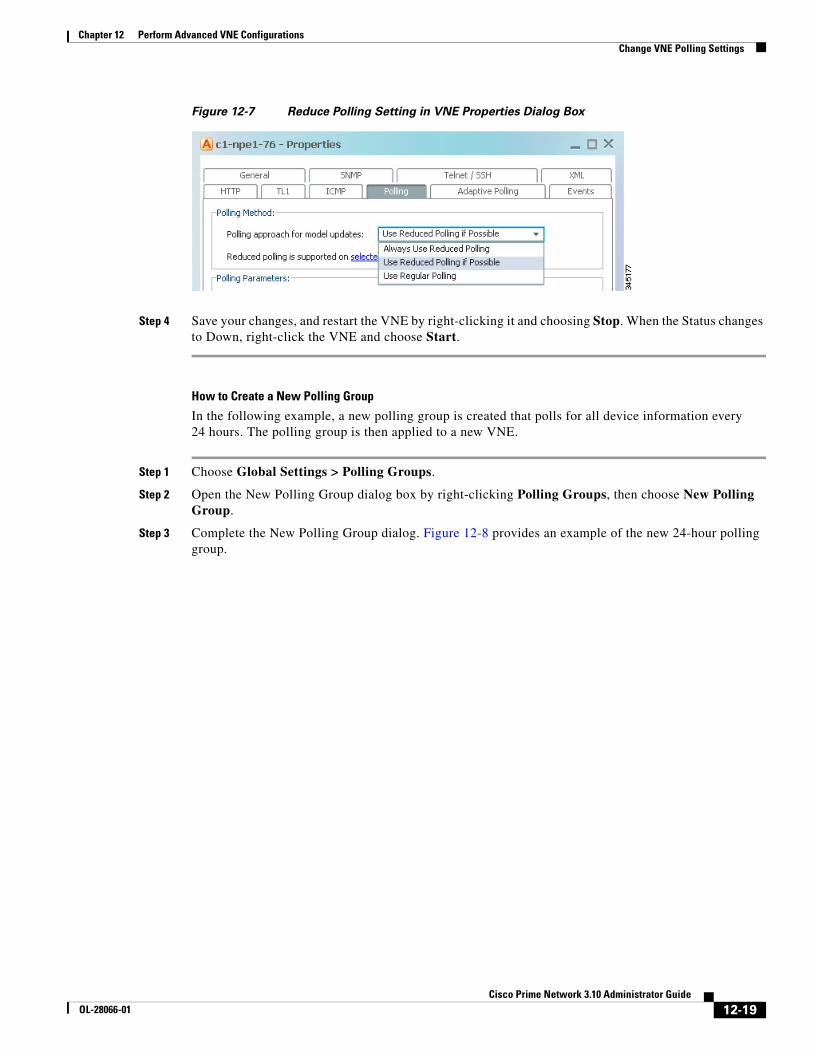
12-19Cisco Prime Network 3.10 Administrator Guide
OL-28066-01
Chapter 12 Perform Advanced VNE Configurations Change VNE Polling Settings
Figure 12-7 Reduce Polling Setting in VNE Properties Dialog Box
Step 4 Save your changes, and restart the VNE by right-clicking it and choosing Stop. When the Status changes to Down, right-click the VNE and choose Start.
How to Create a New Polling Group
In the following example, a new polling group is created that polls for all device information every 24 hours. The polling group is then applied to a new VNE.
Step 1 Choose Global Settings > Polling Groups.
Step 2 Open the New Polling Group dialog box by right-clicking Polling Groups, then choose New Polling Group.
Step 3 Complete the New Polling Group dialog. Figure 12-8 provides an example of the new 24-hour polling group.
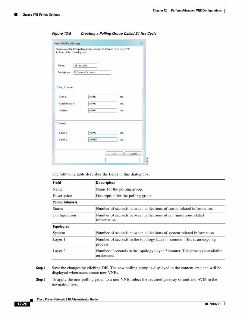
12-20Cisco Prime Network 3.10 Administrator Guide
OL-28066-01
Chapter 12 Perform Advanced VNE Configurations Change VNE Polling Settings
Figure 12-8 Creating a Polling Group Called 24 Hrs Cycle
The following table describes the fields in this dialog box.
Step 4 Save the changes by clicking OK. The new polling group is displayed in the content area and will be displayed when users create new VNEs.
Step 5 To apply the new polling group to a new VNE, select the required gateway or unit and AVM in the navigation tree.
Field Description
Name Name for the polling group.
Description Description for the polling group.
Polling Intervals
Status Number of seconds between collections of status-related information.
Configuration Number of seconds between collections of configuration-related information.
Topologies
System Number of seconds between collections of system-related information.
Layer 1 Number of seconds in the topology Layer 1 counter. This is an ongoing process.
Layer 2 Number of seconds in the topology Layer 2 counter. This process is available on demand.

12-21Cisco Prime Network 3.10 Administrator Guide
OL-28066-01
Chapter 12 Perform Advanced VNE Configurations Change VNE Polling Settings
Step 6 Right-click the AVM, then choose New VNE. The New VNE dialog box is displayed, opened to the General tab.
Step 7 Complete the dialog as described in Add a New Device Type, page 4-17.
Apply the 24 hrs cycle polling group to the VNE by clicking the Polling tab and selecting 24 hrs cycle from the Polling Parameters Group dropdown list, as shown in Figure 12-9.
Figure 12-9 Applying the 24 Hrs Cycle Polling Group to a VNE
Step 8 Click OK. The new VNE is created, and it will poll the device according to the settings in the 24 hrs cycle polling group.
Smooth PollingEach VNE uses device registrations (commands) to collect different kinds of data from the associated network element. Each registration specifies the commands required to obtain a specific given item of data, and can be configured with a specific polling interval or logically associated with one of the polling intervals on a per device/VNE basis.
The smooth polling mechanism that takes commands in the same polling cycle, and spreads their execution throughout the polling cycle. Rather than using a timer-based approach (where a large number of commands will be potentially scheduled for execution at the same time), the smooth polling method generates a random number (within the polling interval) for the next execution. This ensures that the commands get executed at least once within the required period, while also reducing the probability that two or more commands will run at the same time. This “smooths out” the load of the management protocols on the network and reduces their impact. Obviously, the longer the polling interval, the more effective smooth polling can be.
Note that smooth polling augments regular polling only after the completion of the first poll. Smooth polling is enabled in Prime Network by default.

12-22Cisco Prime Network 3.10 Administrator Guide
OL-28066-01
Chapter 12 Perform Advanced VNE Configurations Change VNE Polling Settings
How to Enable or Disable Smooth Polling
While it is rare that you will need to change the smooth polling setting, you can disable it if a VNE’s polling intervals are extremely small.
Note Changes to the registry should only be carried out with the support of Cisco. For details, contact your Cisco account representative.
Step 1 Log into the gateway as pnuser and change to the Main directory.
# cd $ANAHOME/Main
Step 2 Issue the appropriate command for a VNE where unit-IP is the unit IP address, avmxxx is the AVM ID, vne-key is the VNE name (if you are running this command on AVMs on the gateway server, unit-IP should be 127.0.0.1):
• To disable smooth polling:
Note Disabling smooth polling will likely result in higher CPU usage.
# ./runRegTool.sh -gs 127.0.0.1 set unit-IP "avmxxx/agents/da/vne-key/smoothpollingenabled" false
• To revert to the default setting (enabled):
# ./runRegTool.sh -gs 127.0.0.1 unset unit-IP "avmxxx/agents/da/vne-key/smoothpollingenabled"
Step 3 Restart the VNE.
Smart Polling (On-Demand Polling)When Prime Network receives an incoming notification about a model change, the event provides information about the change but not about other components that may be affected by the change. For this reason Prime Network polls for this information that can affect the VNE model.
Sometimes queries are repeatedly submitted to a device. Common cases for this are when a user opens a Prime Network Path Tracer, window, and when an expedited event is received by Prime Network. To prevent overpolling, the smart polling mechanism uses a polling protection interval that specifies the minimum amount of time that must pass before a query can be sent to a device a second time.
For example, if multiple GUI or BQL users are concurrently using Prime Network Path Tracer, if the paths being viewed have common network elements, the details are collected according to the smart polling interval, and the data is shared without performing duplicate polls.
This example shows how Prime Network uses smart polling when receiving multiple instances of an expedited event:
1. An incoming event notification is classified as an expedited event, so Query A is immediately sent.
2. A few milliseconds later, the same incoming event arrives on an adjacent interface, triggering Query A again.
If the interval was 10 seconds, and the second instance of Query A arrived 7 seconds after the first instance of Query A, the second query would be dropped.
12-23Cisco Prime Network 3.10 Administrator Guide
OL-28066-01
Chapter 12 Perform Advanced VNE Configurations Change Settings That Determine Device Reachability
For expedited queries, Prime Network will queue the query to run when the interval is complete. Using the previous example, suppose the first instance of the query arrived at 12:00:00. The second instance arrives at 12:00:07. Because the query is expedited, the second query is queued to run at 12:00:10 (10 seconds after the first query).
If you change the smart polling interval, keep the following in mind:
• If the interval is too short, Prime Network might report false alarms.
• If the interval is too long, Prime Network will not report current data.
Therefore, the interval value should be based on the amount of time required for the network to stabilize after a change.
Note This procedure requires a gateway restart.
Step 1 Log into the gateway as pnuser and change to the Main directory.
# cd $ANAHOME/Main
Step 2 Issue the following command to change the polling-protection-interval for all commands from the default of 0 to value milliseconds. (The text that precedes this procedure provides general guidelines for specifying value.)
# ./runRegTool.sh -gs 127.0.0.1 set 0.0.0.0 "site/instrumentordefaults/baseCommand/polling-protection-interval" value
Step 3 Restart the gateway server:
# networkctl restart
Change Settings That Determine Device Reachability Prime Network VNEs communicate with network devices using a variety of protocols, and traps and syslogs. To determine the reachability of specific protocols, Prime Network runs multiple connectivity tests to check the device reachability.
The status of all of these protocols determine whether a device is reachable. By default, Prime Network marks a device as unreachable only when all enabled protocols are down; that is, the protocols are not responding, and the device is not generating syslogs or traps. However, you can change this behavior to fit your network.
These topics describe how reachability is determined and how you can change this behavior to fit the needs of your network:
• VNE Management Communication Policies and How To Change Them, page 12-24
• Protocol Reachability Tests, page 12-26
• Change How Protocols are Tested for Reachability, page 12-29

12-24Cisco Prime Network 3.10 Administrator Guide
OL-28066-01
Chapter 12 Perform Advanced VNE Configurations Change Settings That Determine Device Reachability
VNE Management Communication Policies and How To Change ThemThe management communication policy determines when Prime Network changes a VNE communication state to Device Unreachable or Device Partially Reachable. The policies allow you to decide how more or less strictly you want to track protocol health. Figure 4-12 on page 4-45 illustrates how you can find out which management communication policy is being used by a VNE. Table 12-7 describes the supported policies.
Note All changes to the registry should only be carried out with the support of Cisco. For details, contact your Cisco account representative.
By default, Prime Network uses the ensure-management policy. You can check the policy that is being used with the following command:
# cd $ANAHOME/Main# ./runRegTool.sh -gs 127.0.0.1 get 127.0.0.1 "site/agentdefaults/da/dcs/type/com.sheer.metrocentral.coretech.common.dc.ManagedElement/Reachability/policy"ensure-management#
If you want to change to a different management communication policy, see the instructions in Change How Protocols are Tested for Reachability, page 12-29.
Table 12-7 Supported VNE Management Communication Policies
Management Policy Criteria for Determining Device Reachability
notstrict Device Unreachable state change when:
• All of the enabled protocols are down, and
• No traps or syslogs were sent by the device for the past 6 minutes.
Device Partially Reachable state change when:
• All of the enabled protocols are down.
• Traps or syslogs are being sent by device.
ensure-management (Default) Device Unreachable state change when:
• All of the enabled protocols are down.
The status of traps/syslogs is not considered. (Because the state goes directly to Device Unreachable, you will never see the Device Partially Reachable communication state when using this policy.)
strict Device Unreachable state change when:
• At least one of the enabled protocols are down.
The status of traps/syslogs is not considered. (Because the state goes directly to Device Unreachable, you will never see the Device Partially Reachable communication state when using this policy.)

12-25Cisco Prime Network 3.10 Administrator Guide
OL-28066-01
Chapter 12 Perform Advanced VNE Configurations Change Settings That Determine Device Reachability
Changing the Management Communication Policy and Policy
The following procedure explains how to configure Prime Network to use a different policy to determine device reachability.
Note All changes to the registry should only be carried out with the support of Cisco. For details, contact your Cisco account representative.
Use runRegTool.sh to make your registry changes, using the following format:
runRegTool.sh -gs 127.0.0.1 set 0.0.0.0 “site/agentdefaults/da/type/com.sheer.metrocentral.coretech.common.dc.ManagedElement/Reachability/policy” value
The following table describes the policy key.
Note The following procedure requires a gateway restart.
Step 1 Log into the gateway as pnuser and change to the Main directory.
# cd $ANAHOME/Main
Step 2 Change the policy using the following command. This example changes the policy from ensure-management (the default) to strict:
# ./runRegTool.sh -gs 127.0.0.1 set 0.0.0.0 "site/agentdefaults/da/dcs/type/com.sheer.metrocentral.coretech.common.dc.ManagedElement/Reachability/policy" strict
Step 3 Restart Prime Network:
# cd $ANAHOME/Main# networkctl restart
Table 12-8 Registry Setting for Reachability Policies
Registry Entry (Key) Description Default Value
policy Management communication policy Prime Network should use. Supported values are strict, ensure-management, or notstrict. For information on the policies, see VNE Management Communication Policies and How To Change Them, page 12-24.
ensure-management

12-26Cisco Prime Network 3.10 Administrator Guide
OL-28066-01
Chapter 12 Perform Advanced VNE Configurations Change Settings That Determine Device Reachability
Protocol Reachability TestsThese topics describes the tests Prime Network conducts to check the health of the SNMP, Telnet, XML, ICMP, and HTTP protocols. Settings for all of the protocols are listed in Table 12-9 on page 12-30. You can check Prime Network Vision to get details about the health of each protocol (see Figure 4-12 on page 4-45).
SNMP
SNMP connectivity is determined by the IP address of the device. The VNE polls the sysObjectId.0 (which is assumed to be available, simple, and immediate) and waits for a response (such as “.1.3.6.1.2.1.1.2.0”). The registry entries that control SNMP reachability testing are provided in Table 12-9 on page 12-30.
The following steps describe how Prime Network checks the health of the SNMP protocol.
How these values work together is illustrated in Figure 12-10.
Step Description
Step 1 The VNE detects a reachability problem.
Step 2 The VNE begins an SNMP reachability command cycle (the cycle is represented by reachabilityretry).
The number of commands that are sent in each command cycle is determined by the value of retries. In this illustration, retries=3 and timeout=5 seconds.
a. The VNE sends an SNMP reachability command (a character) to the device. This is the first retry; retry=1.
b. If the device does not respond within timeout x retry (5 seconds x 1), the SNMP command is repeated. The VNE sends another SNMP reachability command (this is retry 2).
c. If the device does not respond within timeout x retry (5 seconds x 2), the SNMP command is repeated (this is retry 3).
This continues until retries SNMP commands have been sent. This completes one reachability command cycle.
Step 3 The value of reachabilityretries is decremented by 1.
Step 4 The mechanism waits the period of time specified by reachabilityinterval.
Step 5 The mechanism repeats the reachability command cycle (Step 2) until reachabilityretries equals
Step 6 The SNMP protocol is marked Down.

12-27Cisco Prime Network 3.10 Administrator Guide
OL-28066-01
Chapter 12 Perform Advanced VNE Configurations Change Settings That Determine Device Reachability
Figure 12-10 SNMP Reachability Testing
By default, lazyreachability is disabled. This means the default reachability algorithm is proactive—the VNE sends an SNMP request to the device and expects a response. If a response is not received within a certain amount of time, the SNMP protocol is marked as Down. However, if the lazyreachability registry key is enabled, the VNE will not be proactive. Instead, the VNE will wait until a regular query is sent to the device, and if no result is received, the VNE marks the protocol as Down.
Telnet and XML
Telnet connectivity is determined by the IP address of the device. The VNE sends a space and carriage return and waits for the device to echo the prompt. The registry entries that control Telnet reachability testing are provided in Table 12-9 on page 12-30.
Note Prime Network uses these same tests for XML reachability testing. The only difference is that instead of sending a space and a carriage return, the VNE sends a request to sample the serial number of the device.
The following describes the two most common scenario for Telnet problems.
SendSNMP reachability command
Timeout is incremented according to retries.In this case, timeout = 5 seconds and retries = 3.
(reachabilityretry) (reachabilityretry)
retries = 3 retries = 3
Send SNMP reachability command
reachabilityinterval= 30 secs
5 secs 10 secs 15 secs
timeout timeout +timeout
timeout +timeout +timeout
5 secs 10 secs 15 secs
timeout timeout +timeout
timeout +timeout +timeout
reachabilityretries = 2
2792
87
MarkSNMPdown
Scenario Description
Scenario 1 A running command times out and the connection to the device is lost. The VNE will attempt to start a new connection with the device.
1. The VNE sends a message (a space and carriage return) to the device to initiate a login sequence.
2. Starting from when the login sequence was initiated, if there is no response within logintimeout, the protocol remains marked Down.
Scenario 2 The device is not responding in a timely manner to a bulk command. The VNE will begin monitoring the device as follows.
1. Starting from when the first bulk request was sent, if there is no response within receivetimeout, the VNE repeats the request.
2. If there is no response within workingtimeout, the protocol is marked Down.

12-28Cisco Prime Network 3.10 Administrator Guide
OL-28066-01
Chapter 12 Perform Advanced VNE Configurations Change Settings That Determine Device Reachability
Figure 12-11 illustrates Scenario 2, where a device is not returning timely responses to a bulk command.
Figure 12-11 Telnet Reachability Testing When Bulk Command Not Completed
Sometimes it is not necessary for the VNE to maintain an open Telnet connection to a device, even if the session is idle. This is illustrated in Figure 12-12:
a. The VNE sends Telnet reachability command (keepalive message) to the device. The keepalive message consists of a space and carriage return.
b. If the device does not respond within reachabilityinterval, the protocol is marked Down.
Figure 12-12 Reachability Testing to Retain Telnet Connection
Finally, if an open Telnet session is idle for an amount of time that exceeds idletime, Prime Network closes the connection. If the protocol connection is dropped, it is possible that reachability problems may go undetected by Prime Network until the Telnet connection is needed.
By default, lazyreachability is disabled. This means the default reachability algorithm is proactive—the VNE sends a Telnet request to the device (and a space and a newline character) and expects a response. If a response is not received within a certain amount of time, the Telnet protocol is marked as Down. If the lazyreachability registry key is enabled, the VNE will not be proactive. Instead, the VNE will wait until a regular query is sent to the device, and if no result is received, the VNE marks the protocol as Down.
Send bulkTelnet request
Send bulkTelnet request
Send bulkTelnet request
MarkTelnet down
workingtimeout
receivetimeout receivetimeout
2792
88
MarkTelnet down
Sendkeepalivemessage
Sendkeepalivemessage
Sendkeepalivemessage
Sendkeepalivemessage
reachabilityinterval reachabilityinterval reachabilityinterval
2792
89

12-29Cisco Prime Network 3.10 Administrator Guide
OL-28066-01
Chapter 12 Perform Advanced VNE Configurations Change Settings That Determine Device Reachability
ICMP
ICMP connectivity is determined by sending a ping to a device and waiting for a reply. The registry entries that control ICMP reachability testing are provided in Table 12-9 on page 12-30. Due to a system limitation, ICMP packets cannot be sent. ICMP connectivity is therefore determined by attempting to establish a TCP connection on port 7 (Echo).
1. The VNE sends a ping to the device, and the device does not respond within timeout.
2. The first step is repeated retries times.
3. If there is still not response, the ICMP protocol is marked Down, and the VNE starts this process again.
HTTP
HTTP connectivity is determined by trying to log into the device. If the device does not respond within timeout, the device is marked as Down.
Change How Protocols are Tested for ReachabilityTable 12-9 lists the registry settings that control how Prime Network tests the SNMP, Telnet, XML, ICMP, and HTTP protocols to ensure reachability. These tests are described in Protocol Reachability Tests, page 12-26.
Note Because many VNEs may be impacted, we recommend that you change these settings during a maintenance window. Avoid setting numbers too low (which can trigger false “unreachable” messages) or too high (which may cause real problems to go undetected).
Note All changes to the registry should only be carried out with the support of Cisco. For details, contact your Cisco account representative.

12-30Cisco Prime Network 3.10 Administrator Guide
OL-28066-01
Chapter 12 Perform Advanced VNE Configurations Change Settings That Determine Device Reachability
Table 12-9 Registry Settings for Device Protocol Reachability
Registry Entry DescriptionDefault Value
SNMP
trackreachability Enable reachability detection process for SNMP true
timeout Timeout between each request (in seconds) 5
retries Number of retries for each request 3
reachabilityinterval Interval for device reachability command (in seconds) 30
reachabilityretries Number of retries until a reachability problem is determined 1
lazyreachability Send reachability request when normal polling occurs rather than sending a dedicated command.
false
Telnet and XML
trackreachability Enable reachability detection process for Telnet or XML true
reachabilityinterval Interval for device reachability command (in seconds) 30
lazyreachability Send reachability request when normal polling occurs rather than sending a dedicated command.
false
logintimeout Timeout for login part (in seconds) 30
receivetimeout Timeout for receiving initial device response to a command, or for executing a “more” or other interactive user signal (for responses that have multiple pages or bulk) (in seconds)
20
workingtimeout Timeout for not receiving a device response to any commands (in seconds) 60
idletime Amount of time where no commands are sent to device, after which to disconnect the Telnet or XML session (in seconds)
300
ICMP
trackreachability Enable reachability detection process for ICMP ping true
retries Number of retries for each ICMP ping 1
timeout Timeout for not receiving a device response to the ICMP ping (in seconds) 5
HTTP
trackreachability Enable reachability detection process for HTTP true
lazyreachability Send reachability request when normal polling occurs rather than sending a dedicated command.
false
timeout Timeout for login (in seconds). 3
connectionReuse Use the same connection to send and receive multiple HTTP requests/responses instead of opening a new connection for each request/response pair. Also known as HTTP keepalive.
true
authenticationRequired Require device username and password when using HTTP. true
12-31Cisco Prime Network 3.10 Administrator Guide
OL-28066-01
Chapter 12 Perform Advanced VNE Configurations Change How VNE Commands Are Executed (Collectors Command and Priorities)
Change How VNE Commands Are Executed (Collectors Command and Priorities)
The following topics provide a high-level description of how VNE collectors execute the commands required to build a model of a device, and how to adjust the way Prime Network executes these commands:
• What Are Collectors and Command Priorities?, page 12-31
• Considerations for Using Fast Commands and Fast Collectors, page 12-32
• Expedited Commands and Activation Scripts and Fast Collectors, page 12-33
• Configuring a Command With the “Fast” Command Priority, page 12-34
• Creating a Fast Collector for a VNE, page 12-35
What Are Collectors and Command Priorities?Prime Network discovers and models a network element using commands that are called registrations. Registrations are forwarded to a VNE’s collectors, which are the VNE components that communicate with the physical network element. By default, each VNE is configured to have two collectors: an SNMP collector and a Telnet collector. These collectors can execute only one command at a time. Because many commands are sent to the network element during modeling, each collector maintains a queue of commands. When a collector is busy, any new incoming commands are placed at the end of the queue (FIFO, or first in, first out). When a collector finishes with one command, it executes the next command in the queue in a serial fashion.
In most cases, executing command in a serial fashion is adequate. However, it may not be efficient enough for network elements with large configurations, for the following reasons:
• When modeling begins, the collector receives many commands in a short amount of time. This results in a very long command queue.
• Some commands require extra time to execute (for example, when sampling a routing table for a Cisco CRS-1). The result is that commands at the end of the queue experience long delays before execution. This is particularly problematic for expedited commands and activation script commands (these cases are discussed in Expedited Commands and Activation Scripts and Fast Collectors, page 12-33).
Note Slow response could be the result of a high CPU utilization problem. See CPU Utilization Problems: Where to Begin, page 12-2.
Command Priorities and Command Queues: Normal and Fast
To prevent delays in command execution, Prime Network uses a command priority mechanism. Every command is given one of the following priorities:
• Fast—High priority
• Normal—Normal priority (the default)
To deal with the two priorities, each collector maintains two queues: a fast queue for the fast commands and a normal queue for the normal commands. When a collector is available it will execute commands in the fast queue first. It will not execute any commands in the normal queue until the fast queue is empty.

12-32Cisco Prime Network 3.10 Administrator Guide
OL-28066-01
Chapter 12 Perform Advanced VNE Configurations Change How VNE Commands Are Executed (Collectors Command and Priorities)
Fast Collectors
Even a fast priority command can suffer a delay if, when it is sent, the collector is already busy executing a very large normal priority command.
For this situation, you can configure an additional collector called a fast collector. The fast collector is a special collector that is dedicated to commands in the fast queue. When the fast queue is empty, the fast collector is dormant.
For example, if you configure a fast collector for the Telnet protocol, Prime Network will have:
• One Telnet fast collector that only executes commands in the Telnet fast queue. If the Telnet fast queue is empty, the Telnet fast collector is dormant.
• One Telnet (default) collector that executes commands in both the Telnet normal and fast queues. (Remember that the default collector always executes commands in the fast queue first. If the Telnet fast collector is occupied, the Telnet (default) collector will execute the next command in the fast queue.).
Collectors and Thread Sharing
To decrease the overall number of threads used at the VNE layer, each AVM maintains pools of threads that are shared by the VNEs. VNEs acquire and release the threads as needed, in an asynchronous fashion.
One thread pool is dedicated to activation scripts. This thread pool grows dynamically, up to the number of VNEs in the AVM. Each thread is destroyed after 60 seconds of inactivity. Even if you expect a large number of activation scripts to run in parallel, you should see no IO degradation. However, we recommend that you do not run more than 100 concurrent activation scripts on a unit.
Considerations for Using Fast Commands and Fast CollectorsThere are obvious benefits of marking commands with a fast priority, and configuring and additional fast collector. But these methods also have some cost and possible risks.
Risks of Using the Fast Command Priority
Only a small number of registration commands should have a fast command priority. If too many commands are marked as fast, the queue for the fast commands can become long, with the following results:
• The purpose of command priorities is defeated because even fast commands have to wait in a queue.
• The normal commands are delayed even further because they are not executed until the (long) fast queue is empty.

12-33Cisco Prime Network 3.10 Administrator Guide
OL-28066-01
Chapter 12 Perform Advanced VNE Configurations Change How VNE Commands Are Executed (Collectors Command and Priorities)
Risks of Using Fast Collectors
We recommend that you do not configure an additional fast collector for the following reasons:
• The additional collector can impact system scale performance. In Prime Network, because each collector works in a separate thread, every VNE configured with a fast collector will consume an additional thread. If a large number of VNEs are configured with fast collectors, system performance can be significantly degraded.
• The additional collector could significantly reduce overall management traffic throughput. Every VNE configured with a fast collector opens an additional management connection to a device. Opening multiple connections in parallel can cause a significant increase in NE CPU levels, which can greatly reduce the overall throughput of management traffic.
General Recommendation for Fast Commands and Fast Collectors
For commands that are high priority, mark the command with the fast command priority. Do not configure an additional fast collector unless the command takes an unusually long time to execute.
Expedited Commands and Activation Scripts and Fast CollectorsBy default, all expedited commands, activation scripts, and CPU monitoring commands have a fast command priority.
CPU monitoring commands have a fast command priority so that Prime Network can quickly identify and respond to high CPU issues that may affect the device and overall system.
Expedited commands have a fast command priority, but only for their first execution. Normally, expedited command execute with little delay. When it has successfully executed, the expedited command returns to a normal command priority. You should only consider using an additional fast collector if expedited commands are consistently delayed by other commands that require a long time to execute. To find out which commands are expedited, see the specific syslog, trap, and command descriptions in:
• Cisco Prime Network 3.10 Supported Syslogs
• Cisco Prime Network 3.10 Supported Traps
• Cisco Prime Network 3.10 User Guide
Activation scripts (which are converted into commands) have a fast command priority by default. However, activation scripts must adhere to a more strict timeout mechanism than expedited commands.
All commands—expedited commands or commands in activation scripts—have a timeout period which begins when command execution starts. But activation scripts have an additional timeout on the gateway. This gateway timeout begins when the commands are sent to the VNE. If a collector is occupied for an extended period, the gateway timeout may expire and the activation will fail.
If activation commands are timing out, consider the following approaches:
• For devices with marginal timeouts (that is, devices for which there is a very small difference between the script timeout and the time required for the longest command to execute), consider slightly increasing the activation script timeout. However, this is not appropriate for complex device configuration commands.
• For very complex devices with commands that require several minutes to execute, consider configuring an additional fast collector. Increasing the timeout is not appropriate because the increase would have to be sizable. This would result in Prime Network taking a long time to detect activation script failures, hence reducing the system throughput.

12-34Cisco Prime Network 3.10 Administrator Guide
OL-28066-01
Chapter 12 Perform Advanced VNE Configurations Change How VNE Commands Are Executed (Collectors Command and Priorities)
General Recommendation for Using Fast Collectors with Expedited Commands and Activation Scripts
The default behavior (described earlier) should be sufficient for both activation scripts and expedited commands. Consider an additional fast collector only if commands are experiencing unacceptable delays.
Note If you decide to configure additional fast collectors, limit it to the smallest possible number of VNEs—in other words, only for VNEs with the most critical need. Also be sure to monitor the system for any effects on device CPU and system scale performance.
Configuring a Command With the “Fast” Command PriorityBy default, all commands have a normal command priority and are executed by the collector in a FIFO basis. You can mark a command to have the fast (high) command priority, which means it will be placed in the collector’s fast queue rather than its normal queue. Use the following procedure to edit the command priority in the registry.
Note We recommend that you do not change any of these settings. Changes to the registry should only be carried out with the support of Cisco. For details, contact your Cisco account representative.
Before You Begin
• Read Risks of Using the Fast Command Priority, page 12-32.
• Read General Recommendation for Fast Commands and Fast Collectors, page 12-33.
Note This procedure requires a gateway restart.
To set a command priority to fast, use the following procedure.
Step 1 Log into the gateway as pnuser and change to the Main directory:
# cd $ANAHOME/Main
Step 2 Issue the following command to configure commands with the fast command priority. The variable registry-path is the path to the command to be configured. For example, for the CPU usage command in Cisco IOS devices, use the following:
# ./runRegTool.sh -gs 127.0.0.1 set 0.0.0.0 "site/registry-path/cpu usage snmp/instrumentationservices/command/priority” fast
Step 3 Restart the gateway server:
# networkctl restart

12-35Cisco Prime Network 3.10 Administrator Guide
OL-28066-01
Chapter 12 Perform Advanced VNE Configurations Change How VNE Commands Are Executed (Collectors Command and Priorities)
Creating a Fast Collector for a VNEBy default, every protocol has only one collector (that is, no fast collector). You can configure a fast Telnet or SNMP collector for a VNE by editing the registry.
Note Before you configure a fast collector, try using the fast command priority mechanism. See Configuring a Command With the “Fast” Command Priority, page 12-34.
Note We recommend that you do not change any of these settings. Changes to the registry should only be carried out with the support of Cisco. For details, contact your Cisco account representative.
Before You Begin
• Read Risks of Using Fast Collectors, page 12-33.
• Read General Recommendation for Using Fast Collectors with Expedited Commands and Activation Scripts, page 12-34.
To create a fast Telnet or SNMP collector for a specific VNE, use the following procedure.
Step 1 Log into the gateway as pnuser and change to the Main directory:
# cd $ANAHOME/Main
Step 2 Issue the following command to create a new fast collector for a specific VNE. In the following, avmxxx is the AVM ID, vne-key is the VNE name, and vne-ip is the VNE IP address.
If the VNE is on the gateway server, unit-IP should be 127.0.0.1.If the VNE is on a unit server, unit-IP should be the unit’s IP address.
• To create an SNMP fast collector for the VNE with the ID vne-key:
# ./runRegTool.sh -gs 127.0.0.1 set unit-IP "avmxxx/agents/da/vne-key/ips/vne-ip/protocols/snmp/maxfastcollector” 1
• To create a Telnet fast collector for the VNE with the ID vne-key:
# ./runRegTool.sh -gs 127.0.0.1 set unit-IP "avmxxx/agents/da/vne-key/ips/vne-ip/protocols/telnet/maxfastcollector” 1
Step 3 Restart the VNE.
Note Be sure to monitor the system for any effects on device CPU and system scale performance.

12-36Cisco Prime Network 3.10 Administrator Guide
OL-28066-01
Chapter 12 Perform Advanced VNE Configurations Change Settings That Control VNE Data Saved After Restarts
Change Settings That Control VNE Data Saved After RestartsPersistency is the ability to store information in the unit for later use. These topics describe the VNE persistency mechanism in Prime Network:
• Persistency Overview, page 12-36
• Alarm Persistency, page 12-37
• Instrumentation Persistency, page 12-40
• Topology Persistency, page 12-41
Note These topics describe some of the persistency registry settings. Changes to the registry should be performed only with the support of Cisco. For details, contact your Cisco account representative.
Persistency OverviewPersistency information is stored across unit, AVM, and VNE restarts. This accelerates the startup time after restarts because Prime Network does not have to re-poll the complete NE.
VNE data persists during runtime when a VNE polls data from a device, and the VNE updates the files in the file system for changes in the device’s response according to the persistency variables. When a VNE is started or restarted, the persistency information is read from these files once. Every normal polling or refresh that takes place after the first time will read the data from the device itself and not from the files.
VNE data persistency is lost in the following scenarios (but alarm persistency is saved):
• A user manually moves the VNE to another AVM, or moves the parent AVM to another unit.
• A unit server high availability event occurs, causing a unit to switch over to the standby unit.
• The device the VNE models is reconfigured (for example, a new sysOID or software version change).
The upgrade mechanism automatically clears all persistency files on Prime Network gateways and units. This option does not clear the alarm history that is stored in the Prime Network database.
Instrumentation Persistency
Instrumentation persistency is used mainly to:
• Shorten the starting time of VNEs for devices. When the information from the local file system is used, the device’s response time and network latency are eliminated; thus the VNE finishes modeling its first state very quickly.
• Provide information about the old state of the VNE, to initiate alarms if the status has changed while the VNE was unloaded. For example, a Port Down alarm is initiated only if the port status was up and changed to down. This ensures that an alarm is not issued on ports which should be down. By maintaining information about the old state of the port, the system understands whether or not the current state is valid.
• Help lower the CPU load on the device while starting when many polling commands are generated. Also, when persistence data is loaded from the unit, traffic bandwidth between the unit and device is much lower than when the system is loaded using “ordinary” device discovery and modeling.
For more information, see Instrumentation Persistency, page 12-40.

12-37Cisco Prime Network 3.10 Administrator Guide
OL-28066-01
Chapter 12 Perform Advanced VNE Configurations Change Settings That Control VNE Data Saved After Restarts
Topology Persistency
Topology persistency creates topology between devices on startup when the VNE is loaded, instead of performing the entire discovery process. Verification of the links is then performed. For more information, see Topology Persistency, page 12-41.
Alarm Persistency
Alarm persistency saves information about the VNE components that send alarms. When a VNE sends an alarm, the VNE can save this information (that it has sent an alarm of type X). This information can then be used by the VNE components after restarts to verify whether the VNE needs to send clearing alarms where changes have occurred in the device when the VNE was down. For more information, see Alarm Persistency, page 12-37.
Alarm PersistencyAlarm persistency enables the system to clear alarms that relate to events that occurred while the system was down. For example, a Link Down alarm is generated, and then the system goes down. While the system is down, a Link Up event occurs in the network, but because the system is down, it does not monitor the network. When the system goes up, the alarm is cleared because the system remembers that a Link Down alarm exists, and the system needs to clear it by sending a corresponding alarm.
Persisting events are held in the AlarmPersistencyManager. Each VNE contains an AlarmPersistencyManager object. Alarms are added to and removed from the AlarmPersistencyManager object in order to maintain the status of an event, whether it exists in the repository or not; that is, whether an up alarm or a clearing alarm has been generated. Two copies of alarm persistency information are maintained: one in the memory, and the other on disk.
At startup, the AlarmPersistencyManager retrieves the events persisted for the containing VNE. Because alarm persistency is based on a VNE’s IP address, if you change the IP
Event data in the files is updated at the following times:
• At shutdown.
• After a change, when an event is added or removed.
• After a specific interval of time has passed. This prevents data from being rewritten to the persistency file when a stream of events is added or removed during a short period of time, because the data is saved only after the specified period of time has elapsed.
Initialization
Alarm persistency is controlled by settings in the registry. Global alarm persistency information is stored in agentdefaults.xml. The major settings are listed in Table 12-10. The settings for these configurable items only apply when trying to retrieve data from the persistency files. Individual event persistency information is described in Configuring Alarm Persistency for a Specific Event, page 12-38.
Note All changes to the registry should only be carried out with the support of Cisco. For details, contact your Cisco account representative.
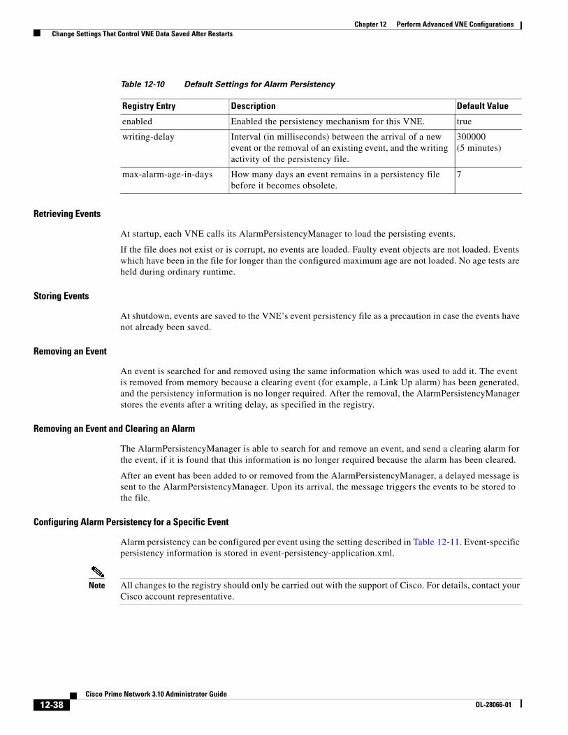
12-38Cisco Prime Network 3.10 Administrator Guide
OL-28066-01
Chapter 12 Perform Advanced VNE Configurations Change Settings That Control VNE Data Saved After Restarts
Retrieving Events
At startup, each VNE calls its AlarmPersistencyManager to load the persisting events.
If the file does not exist or is corrupt, no events are loaded. Faulty event objects are not loaded. Events which have been in the file for longer than the configured maximum age are not loaded. No age tests are held during ordinary runtime.
Storing Events
At shutdown, events are saved to the VNE’s event persistency file as a precaution in case the events have not already been saved.
Removing an Event
An event is searched for and removed using the same information which was used to add it. The event is removed from memory because a clearing event (for example, a Link Up alarm) has been generated, and the persistency information is no longer required. After the removal, the AlarmPersistencyManager stores the events after a writing delay, as specified in the registry.
Removing an Event and Clearing an Alarm
The AlarmPersistencyManager is able to search for and remove an event, and send a clearing alarm for the event, if it is found that this information is no longer required because the alarm has been cleared.
After an event has been added to or removed from the AlarmPersistencyManager, a delayed message is sent to the AlarmPersistencyManager. Upon its arrival, the message triggers the events to be stored to the file.
Configuring Alarm Persistency for a Specific Event
Alarm persistency can be configured per event using the setting described in Table 12-11. Event-specific persistency information is stored in event-persistency-application.xml.
Note All changes to the registry should only be carried out with the support of Cisco. For details, contact your Cisco account representative.
Table 12-10 Default Settings for Alarm Persistency
Registry Entry Description Default Value
enabled Enabled the persistency mechanism for this VNE. true
writing-delay Interval (in milliseconds) between the arrival of a new event or the removal of an existing event, and the writing activity of the persistency file.
300000 (5 minutes)
max-alarm-age-in-days How many days an event remains in a persistency file before it becomes obsolete.
7

12-39Cisco Prime Network 3.10 Administrator Guide
OL-28066-01
Chapter 12 Perform Advanced VNE Configurations Change Settings That Control VNE Data Saved After Restarts
In the following LDP Neighbor Loss alarm, the LDP Neighbor Down event marks the alarm as present in the system (persisted), and the LDP Neighbor up event is used to clear the alarm from persistency (unpersist):
<key name="LDP neighbor loss"> <entry name="default">event-persistency-application/templates/generic persistency event</entry> <key name="sub-types"> <key name="LDP neighbor down"> <entry name="alarm-persistency">persist</entry> </key> <key name="LDP neighbor up"> <entry name="alarm-persistency">unpersist</entry> </key> </key></key>
Alarm Persistency Default Configuration
The following alarms are configured to be persistent.
Table 12-11 Registry Setting for Alarm Persistency for a Specific Event
Registry Entry Description Default Value
alarm-persistency Enable persistency for a specific event. See Alarm Persistency Default Configuration, page 12-39
Table 12-12 Persisted Alarms
all ip interfaces down ds3path port down due to admin link down on unreachable
ascend link down trap ds3path port down due to card link overutilized
bfd connectivity down ds3path port down due to oper log archive disabled
bfd neighbour loss ds3path port down due to upper layer down
low priority member down
bgp link down due to admin ds3path port flapping lsp removed
bgp link down due to oper dual stack IP removed medium priority member down
bgp link down vrf due to admin duplicate ip on vpn found memory overutilized
bgp link down vrf due to oper dwdm controller down mlppp admin down
bgp neighbour loss due to admin dwdm g709 status down mlppp oper down
bgp neighbour loss due to oper efp admin down MPLS TE FRR state changed to active
bgp-neighbor-loss-vrf-due-to-admin efp down due to error disabled MPLS interface removed
bgp-neighbor-loss-vrf-due-to-oper efp oper down ospf neighbor down
bridgeilan ac clear envmon condition syslog pim interface down syslog
bridgeilan ac shutdown envmon fan syslog pim neighbor loss syslog
bridgeilan bridge-domain clear envmon powersupply syslog port down due to admin
bridgeilan bridge-domain shutdown envmon temperature syslog port down due to card out
bridgeilan pseudowire shutdown fabric hardware syslog port down due to card down

12-40Cisco Prime Network 3.10 Administrator Guide
OL-28066-01
Chapter 12 Perform Advanced VNE Configurations Change Settings That Control VNE Data Saved After Restarts
Instrumentation PersistencyThe instrumentation layer persists the information that was collected from the device to the file system. When the VNE restarts, it uses this information to emulate the device’s response, and thus the VNE can be modeled according to its last persistent state. The next polling instance is performed against the real device.
The registry entries that control instrumentation persistency are provided in Table 12-13.
Note All changes to the registry should only be carried out with the support of Cisco. For details, contact your Cisco account representative.
bridgeilan pseudowire clear flash card removed syslog port down due to oper
card down GRE tunnel down port down due to upper layer down
card down syslog high priority member down port flapping
card out ima admin down rx dormant
cpu overutilized ima oper down rx overutilized
device unsupported interface status down GRE tunnel sonetpath link down
discard packets interface status down connection sonetpath link down due to admin down
dropped packets interface status down non connection sonetpath link down due to card
ds0 bundle admin down keepalive not set sonetpath link down due to oper down
ds0 bundle oper down l2tp peer not established sonetpath link down on unreachable
ds1path link down l2tp sessions count exceeds max threshold
sonetpath port down due to admin
ds1path link down due to admin down lag admin down sonetpath port down due to card
ds1path link down due to card lag oper down sonetpath port down due to oper
ds1path link down due to oper down lag link admin down sonetpath port flapping
ds1path link down on unreachable lag link down on unreachable stop flapping non-cleared
ds1path port down due to admin lag link oper down sub card down
ds1path port down due to card layer 2 aggregation admin down sub card out
ds1path port down due to oper layer 2 aggregation oper down sub-interface admin down
ds1path port down due to upper layer downb
layer 2 tunnel down sub-interface oper down
ds1path port flapping LDP neighbor down tx dormant
ds3path link down link down tx overutilized
ds3path link down due to admin down link down due to admin down vsi admin down
ds3path link down due to card link down due to card vsi oper down
ds3path link down due to oper down keepalive not set
ds3path link down on unreachable link down due to oper down
Table 12-12 Persisted Alarms (continued)

12-41Cisco Prime Network 3.10 Administrator Guide
OL-28066-01
Chapter 12 Perform Advanced VNE Configurations Change Settings That Control VNE Data Saved After Restarts
Topology PersistencyPrime Network supports persistency for Layer 1 topological connections. Layer 1 topology supports one connection per Device Component (DC), so the physical topology reflects a single port connected by a single link.
The following topologies are persisted:
• Layer 1 counter-based topologies.
• Static topologies.
Table 12-13 Registry Settings for Instrumentation Persistency
Registry Entry Description Default Value
persistencydir Specifies the directory in which persistency information is saved on the local file system. This is a relative path. Allowed values are a string that represents the relative directory in the file system.
instrumentor-persistency
persistencylevel Controls the level of persistency to be used. The allowed values are Full (persisted) or Off (not persisted).
These values can be used for certain commands to make sure some are persisted and some are not.
Note If a compound command contains both Full and Off persistency levels, Prime Network will use the full level for all commands.
Full
persistencystorageenabled Controls whether the whole storage mechanism is enabled. true
persistencystorageinterval Interval (in milliseconds) for which the data to be persisted is accumulated and then written to the persistent storage in bulk. Files are only updated if they have changed.
The default value (20 minutes) is a compromise between small intervals (which cause more I/O operations in the local file system) and long intervals (which result in stored information not being up-to-date).
1200000 (20 minutes)
persistencytimeout Timeout period (in milliseconds) at which initial data is marked as obsolete; all subsequent commands will run directly on the device.
If the persistency mechanism is enabled when the instrumentation layer starts, it loads all the data from the files. This data can be used for the commands only the first time they are executed. Some commands can be used for the first time, long after other commands have finished multiple cycles; for example, commands which run only when the status on the device has changed.
The default value (1 minute) is a compromise between a small value (which can cause the instrumentation layer to ignore the persistent data) and a large value (which causes the data to be retrieved long after the VNE has finished loading).
Note We recommend that this value be at least 600000 (1 minute).
600000 (1 minute)

12-42Cisco Prime Network 3.10 Administrator Guide
OL-28066-01
Chapter 12 Perform Advanced VNE Configurations Create Connections for Unmanaged Network Segments (Cloud VNEs and Links)
Static topology, which identifies physical links configured by the user, is persisted once a user configures the static link between the two entities. This link is then stored in the registry, in the AVM key that contains the specific VNE registrations.
For other topologies, every time a link is created, the persistency mechanism writes the link to this file. When a link is disconnected, the file representing the link is removed.
Note Topology persistency assumes that the XID (the unique device component ID) is persistable. For example, the port XID should remain the same after the device reboots or after the VNE reboots. This is not dependent on whether the ifIndex is changed from time to time.
Topology persistency is controlled by the setting listed in Table 12-14.
Note All changes to the registry should only be carried out with the support of Cisco. For details, contact your Cisco account representative.
Create Connections for Unmanaged Network Segments (Cloud VNEs and Links)
Cloud VNEs represent unmanaged network segments that are connected to two or more managed segments. This prevents interruptions to alarm correlations and affected subscribers for the managed segments.
These topics describe how to add and remove links between two ports of two network elements in the network that are connected to some unmanaged network segment through a Cloud VNE. Dynamic links are used to connect these ports to a cloud.
Static links override any existing autodiscovered topology in the system. A static link is identical in all respects to a link that is autodiscovered.
• Unmanaged Segments and Cloud VNEs, page 12-43
• Creating and Deleting Static Links, page 12-50
Note If you create a cloud VNE with a static connection to a device, and you upgrade to a later version of Prime Network, the connection between the cloud VNE and the device may be lost. You should delete and recreate the link.
Table 12-14 Registry Setting for Topology Persistency
Registry Entry Description Default Value
persistency Enable physical topology persistency.
Note We recommend that this entry remain enabled.
true

12-43Cisco Prime Network 3.10 Administrator Guide
OL-28066-01
Chapter 12 Perform Advanced VNE Configurations Create Connections for Unmanaged Network Segments (Cloud VNEs and Links)
Unmanaged Segments and Cloud VNEsThree types of technology simulations are supported for Cloud VNEs: Frame Relay, ATM, and Ethernet. If you want to work with Cloud VNEs with Ethernet support, see Ethernet on Cloud VNEs, page 12-43.
Administrators can create Cloud VNEs that represent:
• A single device to which two or more managed segments of the network can be connected. In this case, the Cloud VNE builds a model with port type and technology that is identical to its adjacent VNEs and virtual forwarding components. Each physical port in a VNE can connect to only one Cloud VNE.
• Multiple unmanaged segments and multiple technologies, as long as each technology is in a different network segment.
• Multiple Cloud VNEs, each one representing a portion of an unmanaged network.
All VNEs can also be configured to connect dynamically to a Cloud VNE. When loading, the VNE gathers whatever data is relevant to the Cloud VNE, and sends the data to it. Upon receiving this information, the Cloud VNE builds the corresponding model to allow the topology to connect the two VNEs.
To create a Cloud VNE, you must do the following:
1. Create the VNE using Prime Network Administration. You only have to provide a name for the VNE. No additional protocols need to be configured for the Cloud VNE. See Ethernet on Cloud VNEs, page 12-43.
2. Connect the cloud VNE to a device, which will automatically populate the Cloud VNE with technology and topology information. See Connecting the Cloud VNE to a Device, page 12-45.
Note Unmanaged segments must be pure switches; no routing can be involved with the segment.
Ethernet on Cloud VNEs
When using an Ethernet LAN cloud to represent unmanaged network segments, be aware of the following:
• For Ethernet interfaces with duplicate IPs, see Configuring Duplicate IP Addresses on Ethernet Interfaces, page 12-44.
• Devices on both sides of the cloud must communicate so that a Cloud VNE can build the forwarding information properly; otherwise, their MAC addresses do not appear in each other’s ARP or bridging tables.
• The logic that builds the bridging table assumes that each port in the network has a unique MAC address. If multiple ports with the same MAC address do exist in the network, the Cloud VNE will not function properly.
• The logic that builds the bridging table assumes there all VLANs in the network have different IDs. If multiple VLANs with the same ID do exist on any of the VNEs connected to the cloud, the VLANs will be connected together on the cloud.
• A router with an interface that is an ingress point of a Martini tunnel (with no IP address configuration) cannot be connected to a cloud. A Layer 2 tunnel represents a point-to-point pseudowire in the network.

12-44Cisco Prime Network 3.10 Administrator Guide
OL-28066-01
Chapter 12 Perform Advanced VNE Configurations Create Connections for Unmanaged Network Segments (Cloud VNEs and Links)
• The size of the Ethernet Cloud VNE depends on the number of devices, their configurations and the number of VLANs that are connected to it.
• The Layer 2 devices in the unmanaged cloud segment cannot contain VLAN rewrite configurations that are not supported by the Cloud VNE.
• The Cloud VNE does not support the Q-in-Q technology. If VLAN stacking is configured on an unmanaged segment, or if ports with Q-in-Q configuration are connected to the cloud, the cloud might not be able to simulate the behavior of the unmanaged segment.
• The Cloud VNE does not have Spanning Tree Protocol (STP) awareness, so any link from a device to the unmanaged network is assumed to be in a nonblocking state. This might cause the forwarding information calculated by the Cloud VNE to be inaccurate.
• By default, Prime Network does not display VLANs that are present on the device and that cannot be deleted, such as restricted Fiber Distributed Data Interface (FDDI), Token Ring, and other nonEthernet VLANs.
Note Most of the Ethernet functionality—namely, MAC and VLAN support—is only available for dynamic links.
Configuring Duplicate IP Addresses on Ethernet Interfaces
Figure 12-13 provides an example of a configuration of duplicate IP addresses on Ethernet interfaces that are connected to the same Cloud VNE.
Figure 12-13 Duplicate IP Addresses on Ethernet Interfaces
In Figure 12-13, a PE router and two CEs are connected to an unmanaged Ethernet access network, represented by a Cloud VNE.
The PE router is connected to the Cloud VNE through Port1. Two interfaces configured on Port1 are connected to different VRFs (VRF A and VRF B). Both VRF interfaces are configured with the same IP address (10.0.0.1). Each interface is configured with a different VLAN encapsulation (VLAN-ID 3 and VLAN-ID 5), and is connected to a different VLAN in the unmanaged network (VLAN 3 and VLAN 5).
The two CEs are connected to different VLANs in the unmanaged network: CE A is connected to VLAN 3 through Port2, and CE B is connected to VLAN 5 through Port3. Both Port2 and Port3 are access ports (that is, untagged ports with no VLAN encapsulation) and are configured with identical IP addresses (10.0.0.2).
1862
07
CE Router A
Interface110.0.0.2
CE Router B
Interface110.0.0.2
CloudVNE
PE Router
Interface 1VRF A10.0.0.1
VLAN ID-3
Interface 2VRF B10.0.0.1
VLAN ID-5
1862
09
MAC1on Port1
MAC2on Port2
MAC3on Port3
VLAN 3
VLAN 5
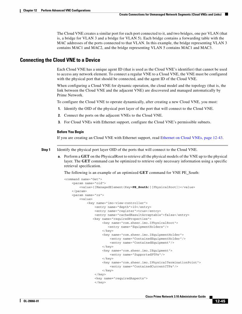
12-45Cisco Prime Network 3.10 Administrator Guide
OL-28066-01
Chapter 12 Perform Advanced VNE Configurations Create Connections for Unmanaged Network Segments (Cloud VNEs and Links)
The Cloud VNE creates a similar port for each port connected to it, and two bridges, one per VLAN (that is, a bridge for VLAN 3 and a bridge for VLAN 5). Each bridge contains a forwarding table with the MAC addresses of the ports connected to that VLAN. In this example, the bridge representing VLAN 3 contains MAC1 and MAC2, and the bridge representing VLAN 5 contains MAC1 and MAC3.
Connecting the Cloud VNE to a Device
Each Cloud VNE has a unique agent ID (that is used as the Cloud VNE’s identifier) that cannot be used to access any network element. To connect a regular VNE to a Cloud VNE, the VNE must be configured with the physical port that should be connected, and the agent ID of the Cloud VNE.
When configuring a Cloud VNE for dynamic operation, the cloud model and the topology (that is, the link between the Cloud VNE and the adjacent VNE) are discovered and managed automatically by Prime Network.
To configure the Cloud VNE to operate dynamically, after creating a new Cloud VNE, you must:
1. Identify the OID of the physical port layer of the port that will connect to the Cloud VNE.
2. Connect the ports on the adjacent VNEs to the Cloud VNE.
3. For Cloud VNEs with Ethernet support, configure the Cloud VNE’s permissible subnets.
Before You Begin
If you are creating an Cloud VNE with Ethernet support, read Ethernet on Cloud VNEs, page 12-43.
Step 1 Identify the physical port layer OID of the ports that will connect to the Cloud VNE.
a. Perform a GET on the PhysicalRoot to retrieve all the physical models of the VNE up to the physical layer. The GET command can be optimized to retrieve only necessary information using a specific retrieval specification.
The following is an example of an optimized GET command for VNE PE_South:
<command name="Get"> <param name="oid"> <value>{[ManagedElement(Key=PE_South)][PhysicalRoot]}</value> </param> <param name="rs"> <value> <key name="imo-view-controller"> <entry name="depth">10</entry> <entry name="register">true</entry> <entry name="cachedResultAcceptable">false</entry> <key name="requiredProperties"> <key name="com.sheer.imo.IPhysicalRoot"> <entry name="EquipmentHolders"/> </key> <key name="com.sheer.imo.IEquipmentHolder"> <entry name="ContainedEquipmentHolder"/> <entry name="ContainedEquipment"/> </key> <key name="com.sheer.imo.IEquipment"> <entry name="SupportedPTPs"/> </key> <key name="com.sheer.imo.IPhysicalTerminationPoint"> <entry name="ContainedCurrentCTPs"/> </key> </key> <key name="requiredAspects"> </key>

12-46Cisco Prime Network 3.10 Administrator Guide
OL-28066-01
Chapter 12 Perform Advanced VNE Configurations Create Connections for Unmanaged Network Segments (Cloud VNEs and Links)
</key> </value> </param></command>
b. Identify the physical layer (port) OID according to port name or location. You will need For example, from the result of the previous step’s GET command, this would be the physical layer OID of port FastEthernet1/0 in PE_South.
<?xml version="1.0" encoding="UTF-8"?><IPhysicalRoot> <ID type="Oid">{[ManagedElement(Key=PE_South)][PhysicalRoot]}</ID> <EquipmentHolders type="IMObjects_Array"> <IChassis> <ID type="Oid">{[ManagedElement(Key=PE_South)][PhysicalRoot][Chassis]}</ID> <ContainedEquipmentHolder type="IMObjects_Array">
....
<IEquipmentHolder> <ID type="Oid">{[ManagedElement(Key=PE_South)][PhysicalRoot][Chassis][Slot(SlotNum=1)]}</ID> <ContainedEquipment type="IModule"> <ID type="Oid">{[ManagedElement(Key=PE_South)][PhysicalRoot][Chassis][Slot(SlotNum=1)][Module]}</ID> <SupportedPTPs type="IMObjects_Array"> <IPortConnector> <ID type="Oid">{[ManagedElement(Key=PE_South)][PhysicalRoot][Chassis][Slot(SlotNum=1)][Module][Port(PortNumber=FastEthernet1/1)]}</ID> <ContainedCurrentCTPs type="IMObjects_Array"> <IPhysicalLayer> <ID type="Oid">{[ManagedElement(Key=PE_South)][PhysicalRoot][Chassis][Slot(SlotNum=1)][Module][Port(PortNumber=FastEthernet1/1)][PhysicalLayer]}</ID> </IPhysicalLayer> </ContainedCurrentCTPs> </IPortConnector> <IPortConnector> <ID type="Oid">{[ManagedElement(Key=PE_South)][PhysicalRoot][Chassis][Slot(SlotNum=1)][Module][Port(PortNumber=FastEthernet1/0)]}</ID> <ContainedCurrentCTPs type="IMObjects_Array"> <IPhysicalLayer> <ID type="Oid">{[ManagedElement(Key=PE_South)][PhysicalRoot][Chassis][Slot(SlotNum=1)][Module][Port(PortNumber=FastEthernet1/0)][PhysicalLayer]}</ID> </IPhysicalLayer> </ContainedCurrentCTPs> </IPortConnector> </SupportedPTPs> </ContainedEquipment> </IEquipmentHolder>
....
</ContainedEquipmentHolder> </IChassis> </EquipmentHolders></IPhysicalRoot>

12-47Cisco Prime Network 3.10 Administrator Guide
OL-28066-01
Chapter 12 Perform Advanced VNE Configurations Create Connections for Unmanaged Network Segments (Cloud VNEs and Links)
The OID is {[ManagedElement(Key=PE_South)][PhysicalRoot][Chassis][Slot(SlotNum=1)][Module][Port(PortNumber=FastEthernet1/0)][PhysicalLayer]}
c. Replace / (the slash) in the port name with \!slash\! when specifying the OID in the CLI command.
For example, the OID from the preceding step should be changed to:
{[ManagedElement(Key=PE_South)][PhysicalRoot][Chassis][Slot(SlotNum=1)][Module][Port(PortNumber=FastEthernet1\!slash\!0)][PhysicalLayer]}
Step 2 Connect the ports to the Cloud VNE. For each VNE that represents a device that is connected to the unmanaged network represented by the Cloud VNE, do the following:
a. Log into the gateway as pnuser.
b. Change to the Main directory:
# cd $ANAHOME/Main
c. Obtain the cloud agentId by running the following command, where cloudAvmId is the ID of the AVM in which the cloud was defined:
cat registry/avmcloudAvmId.xml
In the following example, a cloud was defined on AVM 358:
# cat registry/avm358.xml
<?xml version="1.0" encoding="UTF-8"?><key name="avm358"> <entry name="default">mcvm</entry> <entry name="avmkey">AVM 358</entry> <key name="agents"> <key name="da"> <key name="Cloud"> <entry name="default">sheer/cloud/product/software versions/default version</entry> <entry name="element type">SHEER_NETWORKS_CLOUD</entry> <entry name="deletePersistency">true</entry> <entry name="adaptivePollingType">1</entry> <key name="creationTime"> <entry name="time">1311516933201</entry> </key> <key name="pollingrates"> <entry name="default">pollinggroups/default</entry> </key> <key name="amsi"> <key name="topology"> <key name="dynamic"> <key name="permissible-subnet"> <entry name="subnet">0.0.0.0/0</entry> </key> </key> <key name="static"></key> </key> </key> <key name="maintenance"> <entry name="activated">false</entry> </key> <key name="ips"> <entry name="agentId">784</entry> <key name="Cloud">...

12-48Cisco Prime Network 3.10 Administrator Guide
OL-28066-01
Chapter 12 Perform Advanced VNE Configurations Create Connections for Unmanaged Network Segments (Cloud VNEs and Links)
d. From the gateway, run the following CLI commands:
# ./runRegTool.sh -gs 127.0.0.1 add unit-IP "avmxxx/agents/da/vne-key/dcs/instance/physical-layer-oid/cloud topology"# ./runRegTool.sh -gs 127.0.0.1 set unit-IP "avmxxx/agents/da/vne-key/dcs/instance/physical-layer-oid/cloud topology/id" cloud-agent-ID
The following lists the parameters you must define:
Example:
# ./runRegTool.sh -gs 127.0.0.1 add 192.168.100.1 "avm900/agents/da/PE_South/dcs/instance/{[ManagedElement(Key=PE_South)][PhysicalRoot][Chassis][Slot(SlotNum=1)][Module][Port(PortNumber=FastEthernet1\!slash\!0)][PhysicalLayer]}/cloud topology"# ./runRegTool.sh -gs 127.0.0.1 set 192.168.100.1 "avm900/agents/da/PE_South/dcs/instance/{[ManagedElement(Key=PE_South)][PhysicalRoot][Chassis][Slot(SlotNum=1)][Module][Port(PortNumber=FastEthernet1\!slash\!0)][PhysicalLayer]}/cloud topology/id" 784
The previous example connects a VNE named PE_South (which resides in avm900 on unit 192.168.100.1) with a Cloud VNE that has the agent ID 784. The connection with the Cloud VNE is made using the physical layer of PE_South that has the OID:
{[ManagedElement(Key=PE_South)][PhysicalRoot][Chassis][Slot(SlotNum=1)][Module][Port(PortNumber=FastEthernet1/0)][PhysicalLayer]} is connected to the Cloud VNE with the agent ID 784.
e. Restart the VNE.
Step 3 If the cloud represents an Ethernet access network, configure the permissible subnets on the Cloud VNE. This will permit IP interfaces to connect to other entities only if the interfaces are on the specified subnets. This minimizes the number of connections the Cloud VNE handles.
Note This configuration applies to the Cloud VNE, not to the adjacent VNEs. The most common use case is to configure permissible subnets to allow the connection through all subnets that are connected to the cloud (by configuring 0.0.0.0/0, or 0::0/0 for IPv6).
Parameter Meaning
unit-IP The IP address of the Solaris machine on which the parent AVM resides (for the VNE that will connect to the Cloud VNE). If the AVM is on the gateway server, unit-IP should be 127.0.0.1.
avmxxx The ID of the parent AVM (for the VNE that will connect to the Cloud VNE).
vne-key The name of the VNE which will connect to the Cloud VNE.
physical-layer-oid The OID of the VNE port which will connect to the Cloud VNE. This is the OID you identified in Step 1 of this procedure.
cloud-agent-ID The agent ID of the Cloud VNE. (This is the Cloud VNE you created in Add a New Device Type, page 4-17.)

12-49Cisco Prime Network 3.10 Administrator Guide
OL-28066-01
Chapter 12 Perform Advanced VNE Configurations Create Connections for Unmanaged Network Segments (Cloud VNEs and Links)
For each Cloud VNE, do the following:
a. Log into the gateway as pnuser.
b. Change to the Main directory:
# cd $ANAHOME/Main
c. From the gateway, run the following CLI commands:
# ./runRegTool.sh -gs 127.0.0.1 add unit-IP "avmxxx/agents/da/cloud-vne-key/amsi/topology/dynamic/permissible-subnet"# ./runRegTool.sh -gs 127.0.0.1 set unit-IP "avmxxx/agents/da/cloud-vne-key/amsi/topology/dynamic/permissible-subnet/subnet" permissible-subnet
The following lists the parameters you must define:
Note You can add multiple subnets by running the second CLI command multiple times. Each entry has a different name (e.g., subnet-2, subnet-3, and so on).
Example:
# ./runRegTool.sh -gs 127.0.0.1 add 192.168.100.1 “avm900/agents/da/EthernetCloud/amsi/topology/dynamic/permissible-subnet”# ./runRegTool.sh -gs 127.0.0.1 set 192.168.100.1 “avm900/agents/da/EthernetCloud/amsi/topology/dynamic/permissible-subnet/subnet” 0.0.0.0/0
The previous example configures the permissible subnet 0.0.0.0/0 (meaning all IPv4 subnet connections are allowed), on a Cloud VNE named EthernetCloud (which resides in avm900 on unit 192.168.100.1). To allow all IPv6 subnet connections, use subnet 0::0/0.
d. Restart the Cloud VNE.
Parameter Meaning
unit-IP The IP address of the Solaris machine on which the parent AVM resides (for the VNE that will connect to the Cloud VNE). If the AVM is on the gateway server, unit-IP should be 127.0.0.1.
avmxxx The ID of the parent AVM (for the VNE that will connect to the Cloud VNE).
cloud-vne-key The name of the Cloud VNE (not the adjacent VNE).
permissible-subnet The permissible subnet in the address/mask (such as 192.168.1.0/24).

12-50Cisco Prime Network 3.10 Administrator Guide
OL-28066-01
Chapter 12 Perform Advanced VNE Configurations Create Connections for Unmanaged Network Segments (Cloud VNEs and Links)
Creating and Deleting Static Links
Note If you create a cloud VNE with a static connection to a device, and you upgrade to a later version of Prime Network, the connection between the cloud VNE and the device may be lost. You should delete and recreate the link.
You can create a static link between devices by selecting the two end ports from the device physical inventory in Prime Network Administration. To create a static topological link, you need to supply the exact location of the two end ports (at both ends of the link). The physical hierarchy in which the port is located defines the location of a port, as follows:
Device [shelf] module [submodule] port
Links are bidrectional, and needs to be added only once.
Note By default, a user can view a link in Prime Network Vision only if both link endpoints are in the user’s device scope. If you want to make links viewable if only one endpoint is in a user’s scope, you must edit the registry as described in View Links When Only One Endpoint is in Scope, page 6-4.
The new link is validated after the two ports are selected, but before the link is added. Validation checks:
• The similarity of the connector port types (for example, RJ45 on both sides).
• Layer 2 technology type (for example, ATM OC-3 on both sides).
• The physical layer.
• The operation status of both ports.
• One of the ports is part of another link.
For links between LAGs (IEEE 802.3ad), Prime Network also validates the following:
• The underlying dynamically discovered physical connections do not contradict the new static link.
• Different number of ports configured under the two LAGs.
If validation reveals that one of the ends is part of a static link, you are asked to delete the previous link manually. If validation reveals that one of the ends is part of a dynamic link, the previous link is overridden.

12-51Cisco Prime Network 3.10 Administrator Guide
OL-28066-01
Chapter 12 Perform Advanced VNE Configurations Change VNE Telnet/SSH Login Rates (Staggering VNEs)
Figure 12-14 provides an example of the Topology window.
Figure 12-14 Topology Window
The Topology window displays all static links defined in the system, including the A side and Z side of the link.
To create a new static link:
Step 1 Right-click Topology and choose New Static Link.
Note Any changes made in the Topology window are saved automatically and are registered immediately in Prime Network.
The A Side and Z Side lists enable you to choose the devices and the ports for the static link. When you select a device from the list, the physical inventory of the device is displayed the dialog box.
Step 2 From the A Side and Z Side lists choose a device. The physical inventory of each device is displayed in the related area of the dialog box.
To delete a static link, right-click the link in the Topology window and choose Delete.
Change VNE Telnet/SSH Login Rates (Staggering VNEs)The VNE staggering mechanism controls the rate at which VNEs initiate Telnet/SSH connections across a network managed by Prime Network. This prevents degraded performance on TACACS servers, which can result when there are many concurrent connections.
The mechanism is implemented across the following Prime Network components:
• A gateway service that controls whether VNEs on the unit are permitted to initiate Telnet login sequences. It does this by controlling the number of concurrent connections, and distributing those connections based on how AVMs and VNEs are allocated. The service runs on AVM 99 on the gateway server and units. If there are multiple unit servers, it runs in a distributed fashion across all units. The service ensures that the requests are distributed (it does not specifically monitor the TACACS server).
• A VNE service that requests login permission from its unit server’s management service.

12-52Cisco Prime Network 3.10 Administrator Guide
OL-28066-01
Chapter 12 Perform Advanced VNE Configurations Change VNE Telnet/SSH Login Rates (Staggering VNEs)
• A Telnet protocol service that requests authorization before initiating a login sequence with a device (Telnet and SSH login requests).
When the gateway receives a Telnet authorization request, it queues the requests in a FIFO (first in, first out) manner. If the gateway denies the request, the VNE communication state is changed to Device Partially Managed and a System event is generated (discovery can be prolonged if the VNE is not granted permission). In addition, the VNE Status Details window is updated to say the gateway denied the service. The VNE will continue to request the login, and once a connection is permitted, the VNE communication state changes accordingly and a clearing System event is generated.
Enabling the VNE Staggering Mechanism
This service is disabled by default; in other words, all VNEs are allowed to initiate login sequences. To enable it, use the following procedure:
Step 1 Log into the gateway as pnuser and change to the Main directory.
# cd $ANAHOME/Main
Step 2 Configure the VNE service. You should perform this procedure on the gateway machine.
a. Start the service on all VNEs in a unit.
# ./runRegTool.sh -gs 127.0.0.1 set 0.0.0.0 site/mcvm/services/agentbootstrap/VLAA/enable true
b. Configure the protocol to request authorization before initiating a login:
# ./runRegTool.sh -gs 127.0.0.1 set 0.0.0.0 site/agentdefaults/da/ip_default/protocols/telnet/authorizedlogin true
c. Restart the AVMs on the unit.
Step 3 Configure the gateway service. You should perform this procedure on the gateway machine.
a. Configure the parameters that control the connections.
– Specify the number of permitted concurrent logins:
# ./runRegTool.sh -gs 127.0.0.1 set 0.0.0.0 avm99/services/vneLoginSupervisor/allowedConcurrentLoginsNum logins
We recommend an initial concurrent login setting of 1000:
# ./runRegTool.sh -gs 127.0.0.1 set 0.0.0.0 avm99/services/vneLoginSupervisor/allowedConcurrentLoginsNum 1000
– Specify the amount of time allotted for the VNE to successfully log in. If exceeded, the login is disallowed. (This allows the next VNE in the queue to proceed with its login.)
# ./runRegTool.sh -gs 127.0.0.1 set 0.0.0.0 avm99/services/vneLoginSupervisor/vneFinishedLoginTimeout milliseconds
We recommend an initial setting of 5000 milliseconds (5 seconds):
# ./runRegTool.sh -gs 127.0.0.1 set 0.0.0.0 avm99/services/vneLoginSupervisor/vneFinishedLoginTimeout 5000
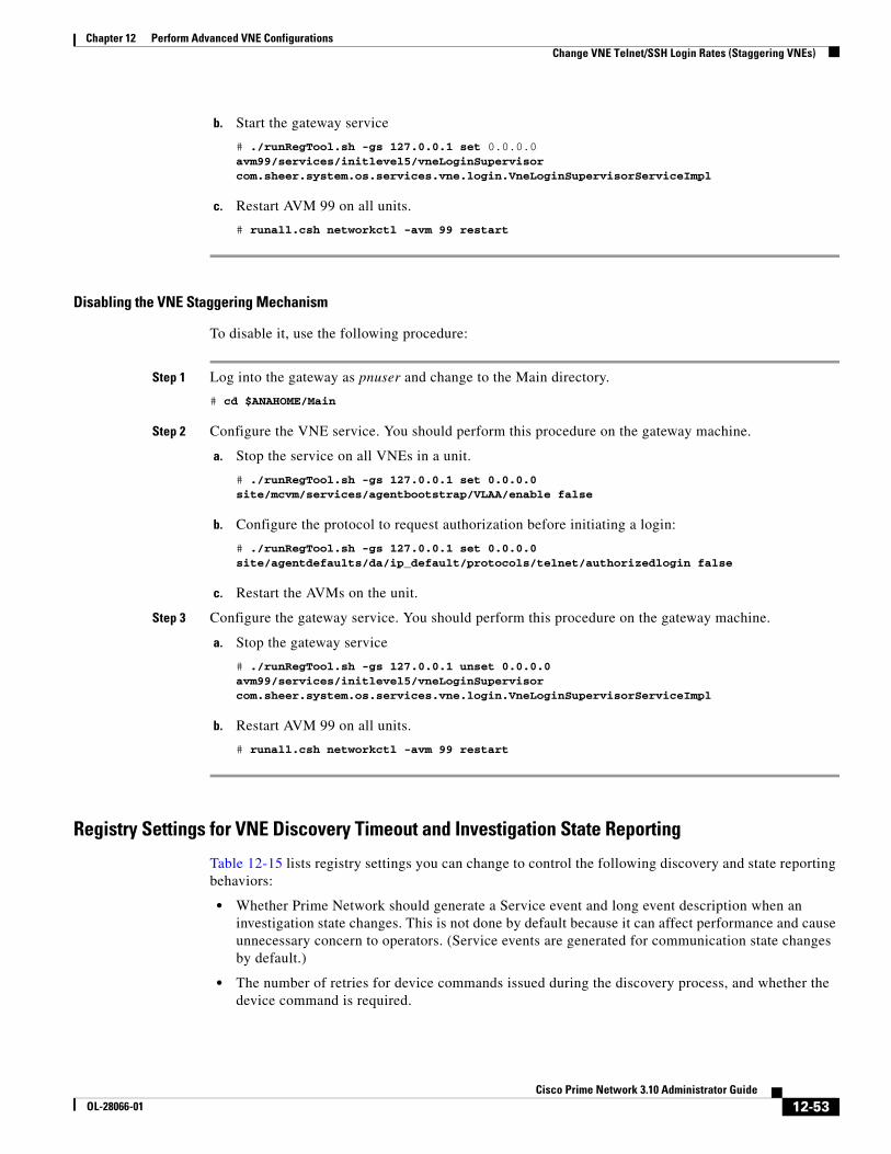
12-53Cisco Prime Network 3.10 Administrator Guide
OL-28066-01
Chapter 12 Perform Advanced VNE Configurations Change VNE Telnet/SSH Login Rates (Staggering VNEs)
b. Start the gateway service
# ./runRegTool.sh -gs 127.0.0.1 set 0.0.0.0 avm99/services/initlevel5/vneLoginSupervisor com.sheer.system.os.services.vne.login.VneLoginSupervisorServiceImpl
c. Restart AVM 99 on all units.
# runall.csh networkctl -avm 99 restart
Disabling the VNE Staggering Mechanism
To disable it, use the following procedure:
Step 1 Log into the gateway as pnuser and change to the Main directory.
# cd $ANAHOME/Main
Step 2 Configure the VNE service. You should perform this procedure on the gateway machine.
a. Stop the service on all VNEs in a unit.
# ./runRegTool.sh -gs 127.0.0.1 set 0.0.0.0 site/mcvm/services/agentbootstrap/VLAA/enable false
b. Configure the protocol to request authorization before initiating a login:
# ./runRegTool.sh -gs 127.0.0.1 set 0.0.0.0 site/agentdefaults/da/ip_default/protocols/telnet/authorizedlogin false
c. Restart the AVMs on the unit.
Step 3 Configure the gateway service. You should perform this procedure on the gateway machine.
a. Stop the gateway service
# ./runRegTool.sh -gs 127.0.0.1 unset 0.0.0.0 avm99/services/initlevel5/vneLoginSupervisor com.sheer.system.os.services.vne.login.VneLoginSupervisorServiceImpl
b. Restart AVM 99 on all units.
# runall.csh networkctl -avm 99 restart
Registry Settings for VNE Discovery Timeout and Investigation State Reporting
Table 12-15 lists registry settings you can change to control the following discovery and state reporting behaviors:
• Whether Prime Network should generate a Service event and long event description when an investigation state changes. This is not done by default because it can affect performance and cause unnecessary concern to operators. (Service events are generated for communication state changes by default.)
• The number of retries for device commands issued during the discovery process, and whether the device command is required.

12-54Cisco Prime Network 3.10 Administrator Guide
OL-28066-01
Chapter 12 Perform Advanced VNE Configurations Track VNE-Related Events
• Whether Prime Network should use the timeout mechanism or the convergence mechanism to determine when the discovery process is complete. (You can also adjust the length of the discovery timeout.)
Note All changes to the registry should only be carried out with the support of Cisco. For details, contact your Cisco account representative.
Track VNE-Related EventsWhen you audit VNE behavior, you are checking the backend process that models and monitors a device in the network. The following table provides ways you can get historical information on VNE-related events. You can tailor your search or reports by specifying keywords (such as VNE).
Table 12-15 Registry Settings for Discovery and Investigation States
Registry Entry Description Default Value
Investigation and Communication State Reporting
site/agentdefaults/da/investigation-progress/investigation-state-update-event
Generate a Service event (in Prime Network Events) when investigation state changes
false
site/agentdefaults/da/investigation-progress/investigation-state-result-summary-event
Include an elaborated report about the investigation state change in the Long Description field of the Service event
false
Device Commands Used for Discovery
site/interfacebasedscheme/default registration/error update tolerance
Allowable number of device command failures, after which an error is generated
3
site/interfacebasedscheme/default registration/required
Designate the device command as required for evaluating an investigation state (insert this after the device command key name)
false
VNE Discovery Period Controls
site/agentdefaults/da/investigation-progress/max-delay-before-managed-state-in-milliseconds
Timeout for VNE discovery process (in milliseconds) (ignored if convergence is being used)
1800000 (30 minutes)
site/agentdefaults/da/investigation-progress/convergence
Use the VNE convergence mechanism to control discovery
false
Information Type Refer to:
Recent System and Security events System and Security tabs in Event GUI client
Historical data on System and Security events for a specific time period and/or specific events
From the main menu, choose Reports > Run Report > Events Reports > Detailed Non-Network Events

12-55Cisco Prime Network 3.10 Administrator Guide
OL-28066-01
Chapter 12 Perform Advanced VNE Configurations Track VNE-Related Events

12-56Cisco Prime Network 3.10 Administrator Guide
OL-28066-01
Chapter 12 Perform Advanced VNE Configurations Track VNE-Related Events

12-57Cisco Prime Network 3.10 Administrator Guide
OL-28066-01
Chapter 12 Perform Advanced VNE Configurations Track VNE-Related Events

12-58Cisco Prime Network 3.10 Administrator Guide
OL-28066-01
Chapter 12 Perform Advanced VNE Configurations Track VNE-Related Events

A-1Cisco Prime Network 3.10 Administrator Guide
OL-28066-01
A P P E N D I X ADevice Configuration Tasks for Modeling
These topics describe the configuration tasks you must perform so that Prime Network can properly model and manage devices.
Note Prime Network automatically performs a series of validation checks for Cisco IOS XR devices. See Cisco IOS XR Devices—Required and Recommended Settings, page A-8.
• Choosing a VNE Scheme (Check Technologies and Device Types), page A-2
• Why Device Configuration Tasks Are Important, page A-7
• Cisco IOS, Cisco IOS XE, and CatOS Devices—Required Settings, page A-7
• Cisco IOS XR Devices—Required and Recommended Settings, page A-8
• Cisco StarOS Devices—Required Settings, page A-11
• Cisco Nexus OS Devices—Required Settings, page A-12
• Cisco Carrier Packet Transport Devices—Required Settings, page A-13
• Cisco Unified Computing System Devices—Required Settings, page A-14
• All Cisco Devices Added Using SSH—Required, Recommended, and Rollback Device Settings, page A-15
• SNMP Traps and Informs—Required Device Settings, page A-15
• Syslogs—Required Device Settings, page A-20
• IP Address Configuration for Traps, Syslogs, and VNEs, page A-22

A-2Cisco Prime Network 3.10 Administrator Guide
OL-28066-01
Appendix A Device Configuration Tasks for Modeling Choosing a VNE Scheme (Check Technologies and Device Types)
Choosing a VNE Scheme (Check Technologies and Device Types)
VNE schemes determine what data should be retrieved for each device, and which commands and protocols Prime Network should use to collect that data. Prime Network provides three schemes by default
While all Cisco devices support either the Product or IpCore scheme, most devices support both schemes but with different levels of support.Table A-1 lists the technologies supported on each scheme. Table A-2 on page A-5 shows whether a specific device type supports a scheme.
Note If none of these schemes meets your needs, you can create your own scheme and it will be added to the Administration GUI client so you can apply it to VNEs. See Create a Custom VNE Scheme, page 4-11.
Scheme Use this scheme for:
Product For devices that are not part of the network core, such as the Cisco 800 Series or 2900 Series.
IpCore For devices that are part of the network core, such as the Cisco 3600 Series, 12000 GSR (Gigabit Switch Router) Series, or CRS (Carrier Routing System) Series.
EMS For devices where only system information and physical inventory should be polled (that is, the minimum amount of data). It is supported on all devices but does not support any technologies.
Default For cases where you are not sure which scheme to choose. Prime Network will use the Product scheme.
Table A-1 Technology Support Based on Schemes
Technology
Scheme
Product IpCore
6PE and 6VPE-based IPv6 Connectivity
Yes Yes
6RD Yes Yes
ACL Yes Yes
APN Yes No
ATM Yes Yes
ATM PW No Yes
Backup Pseudowire No Yes
BFD Yes Yes
BGP Yes Yes
BNG No Yes
Carrier Supporting Carrier (CSC) No Yes
CDP Yes Yes
CEM Group Yes Yes

A-3Cisco Prime Network 3.10 Administrator Guide
OL-28066-01
Appendix A Device Configuration Tasks for Modeling Choosing a VNE Scheme (Check Technologies and Device Types)
CFM Yes Yes
CGN No Yes
Clocking Enhancements No Yes
DSx Yes Yes
EFP No Yes
EGPTC (Evolved GPRS Tunnel Protocol Control)
Yes No
Ethernet Yes Yes
Ethernet Channel Yes Yes
Ethernet IEEE 802.3 Dot1Q/VLAN Yes Yes
Ethernet LMI Yes Yes
Ethernet OAM Yes Yes
Frame Relay Yes Yes
GGSN Yes No
GRE Yes Yes
GTTP (GPRS Tunnel Protocol Prime) Yes No
HDLC Yes Yes
Hierarchical VPLS No Yes
HSRP Yes Yes
IMA Yes Yes
IP Multicast No Yes
IP Pool No Yes
IP Routing Yes Yes
IP and ARP Yes Yes
IPoDWDM No Yes
IPSec1 Yes No
IPSLA Probes (Y.1731) No Yes
IPSLA Responder Yes No
IPv6 Yes Yes
IRB/BVI Yes Yes
ISIS No Yes
ISIS IGPv6 No Yes
L3 VPN and VRF No Yes
LAG (IEEE 802.3ad) Yes Yes
LLDP Yes Yes
Table A-1 Technology Support Based on Schemes (continued)
Technology
Scheme
Product IpCore

A-4Cisco Prime Network 3.10 Administrator Guide
OL-28066-01
Appendix A Device Configuration Tasks for Modeling Choosing a VNE Scheme (Check Technologies and Device Types)
Local Switching Yes Yes
MLACP Yes Yes
MLPPP Yes Yes
MP-BGP No Yes
MPLS No Yes
MPLS Multicast No Yes
MPLS P2MP TE No Yes
MPLS TE-Tunnel (including FRR) No Yes
MPLS TP No Yes
MST-AG/REP-AG Yes Yes
OSPF Yes Yes
P-GW Yes No
POS Yes Yes
PPP Yes Yes
PTP 1588 Yes Yes
PWE3, L2 VPN (Martini) No Yes
PW VCCV No Yes
Q-in-Q (IEEE 802.1ad) Yes Yes
REP Yes Yes
S-GW Yes No
SAE (System Architecture Evolution) with S-GW and P-GW functionality
Yes No
SBC No Yes
SL-XLAT No Yes
SONET/SDH Yes Yes
STP/MSTP/PVST Yes Yes
SVI No Yes
SynCE Yes Yes
TDM Yes Yes
TDM PW No Yes
VC Switching Yes Yes
VLAN Bridging Yes Yes
VPLS No Yes
VRRP No Yes
VTP (VLAN Trunk and Tunneling) Yes Yes
Table A-1 Technology Support Based on Schemes (continued)
Technology
Scheme
Product IpCore
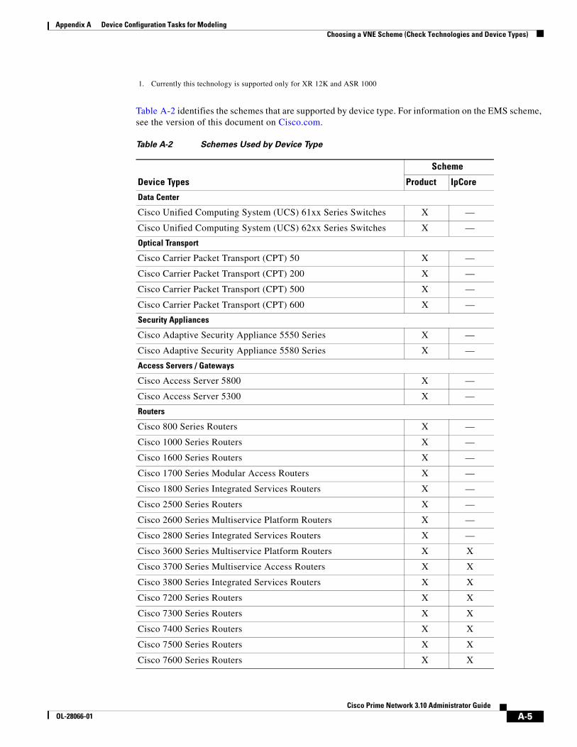
A-5Cisco Prime Network 3.10 Administrator Guide
OL-28066-01
Appendix A Device Configuration Tasks for Modeling Choosing a VNE Scheme (Check Technologies and Device Types)
Table A-2 identifies the schemes that are supported by device type. For information on the EMS scheme, see the version of this document on Cisco.com.
1. Currently this technology is supported only for XR 12K and ASR 1000
Table A-2 Schemes Used by Device Type
Device Types
Scheme
Product IpCore
Data Center
Cisco Unified Computing System (UCS) 61xx Series Switches X —
Cisco Unified Computing System (UCS) 62xx Series Switches X —
Optical Transport
Cisco Carrier Packet Transport (CPT) 50 X —
Cisco Carrier Packet Transport (CPT) 200 X —
Cisco Carrier Packet Transport (CPT) 500 X —
Cisco Carrier Packet Transport (CPT) 600 X —
Security Appliances
Cisco Adaptive Security Appliance 5550 Series X —
Cisco Adaptive Security Appliance 5580 Series X —
Access Servers / Gateways
Cisco Access Server 5800 X —
Cisco Access Server 5300 X —
Routers
Cisco 800 Series Routers X —
Cisco 1000 Series Routers X —
Cisco 1600 Series Routers X —
Cisco 1700 Series Modular Access Routers X —
Cisco 1800 Series Integrated Services Routers X —
Cisco 2500 Series Routers X —
Cisco 2600 Series Multiservice Platform Routers X —
Cisco 2800 Series Integrated Services Routers X —
Cisco 3600 Series Multiservice Platform Routers X X
Cisco 3700 Series Multiservice Access Routers X X
Cisco 3800 Series Integrated Services Routers X X
Cisco 7200 Series Routers X X
Cisco 7300 Series Routers X X
Cisco 7400 Series Routers X X
Cisco 7500 Series Routers X X
Cisco 7600 Series Routers X X

A-6Cisco Prime Network 3.10 Administrator Guide
OL-28066-01
Appendix A Device Configuration Tasks for Modeling Choosing a VNE Scheme (Check Technologies and Device Types)
Cisco 10000 Series Routers X X
Cisco 12000 Series Routers X X
Cisco XR 12000 Series Routers X1 X
Cisco CRS Carrier Routing System (CRS-1 and CRS-3) — X
Cisco ASR 9000 Series Aggregation Services Routers X X
Cisco ASR 1000 Series Aggregation Services Routers X X
Cisco MWR 2900 Series Mobile Wireless Routers X X
Cisco 1900 Series Integrated Services Routers X —
Cisco 2900 Series Integrated Services Routers X —
Cisco 3900 Series Integrated Services Routers X —
Cisco Universal Broadband Router 7200 Series X X
Cisco Universal Broadband Router 10000 Series X X
Cisco 4700 Series Routers X X
Cisco ASR 901 Aggregation Services Series Routers X X
Cisco ASR 903 Aggregation Services Series Routers X X
Cisco ASR 5000 Aggregation Services Series Routers X X
Switches
Cisco Catalyst 1900 Series Switches X —
Cisco Catalyst 2900 Series Switches X —
Cisco ME 3400 Series Ethernet Access Switches X —
Cisco Catalyst 3500 XL Series Switches X —
Cisco Catalyst 3550 Series Switches X —
Cisco Catalyst 3560 Series Switches X —
Cisco Catalyst 3750 Series Switches X —
Cisco Catalyst 3750 Metro Series Switches — X
Cisco Catalyst 4000 Series Switches X —
Cisco Catalyst 4500 Series Switches X —
Cisco Catalyst 4900 Series Switches X —
Cisco ME 4900 Series Ethernet Switch X —
Cisco Catalyst 5000 Series Switches X —
Cisco Catalyst 6500 Series (CatOS) Switches X X
Cisco Catalyst 6500 Series (IOS) Switches X X
Cisco ME 6500 Series Ethernet Switches (6524) X X
Cisco ME 3600X Series Ethernet Access Switches X X
Cisco ME 3800X Series Carrier Ethernet Switch Routers X X
Table A-2 Schemes Used by Device Type (continued)
Device Types
Scheme
Product IpCore

A-7Cisco Prime Network 3.10 Administrator Guide
OL-28066-01
Appendix A Device Configuration Tasks for Modeling Why Device Configuration Tasks Are Important
Why Device Configuration Tasks Are ImportantPrime Network VNEs communicate with network devices using a variety of protocols such as SNMP, Telnet, and ICMP. When a VNE is created, Prime Network connects to the device and runs a variety of registration commands to build a model of the device, based on the scheme that is chosen for the VNE. After modeling, ongoing notifications and protocol communication allows Prime Network to perform ongoing service and technology monitoring, fault processing, topological and model updates, and so forth. If the required device settings are not configured properly, Prime Network cannot retrieve the necessary information from the network element.
For example, if a new interface is added to a Cisco IOS device, but the logging enabled command is not set, Prime Network will not receive a device config change syslog from the device. As a result, Prime Network’s copy of the startup device configuration file is outdated. If the device goes down, when it is restarted, the configuration change is lost.
Note Do not change the device’s default packet size (which 1500 bytes). SNMP requests are sent in bulk by default. A small packet size could result in truncated responses.
Cisco IOS, Cisco IOS XE, and CatOS Devices—Required SettingsThe following settings are required for Cisco IOS, Cisco IOS XE, and Cat OS network elements:
snmp-server community public-cmty ROsnmp-server community private-cmty RW
This settings is required for Cisco IOS and Cisco OS XE devices (it is already set by default for CatOS devices):
snmp-server ifindex persist
Do not change the device’s default packet size (which 1500 bytes). SNMP requests are sent in bulk by default. A small packet size could result in truncated responses.
Cisco Nexus 7000 Series Switches X —
Cisco Nexus 5000 Series Switches X —
Cisco Nexus 1000 Series Switches X —
Cisco Nexus 3000 Series Switches X —
Cisco ACE 4700 Series Access Control Engine X —
Cisco Service Control Engine X —
Generic Devices
Generic devices X —
1. The product scheme is supported Cisco XR 12000 Gigabit Switch Routers.
Table A-2 Schemes Used by Device Type (continued)
Device Types
Scheme
Product IpCore

A-8Cisco Prime Network 3.10 Administrator Guide
OL-28066-01
Appendix A Device Configuration Tasks for Modeling Cisco IOS XR Devices—Required and Recommended Settings
Reduced Polling
For Cisco IOS devices using reduced polling, the following settings are required.
configure terminalarchivelog configlogging enable
If a device is generating configuration change events but Prime Network is not recognizing them, edit the VNE properties (Events tab) and add the IP address you want the VNE to listen to. See VNE Properties: Events, page D-17.
Cisco IOS XR Devices—Required and Recommended SettingsPrime Network validates the configuration of Cisco IOS XR devices before creating VNEs for those devices. The validations are contained in a registration named mis-con, which validates the following:
• The MGBL package is installed.
• The user belongs to root-system.
• XML is enabled on the device. See Enabling XML on a Device, page A-9.
If any of these validations fail, Prime Network generates a System event. To disable this validation for all Cisco IOS XR devices, use the following command from the gateway server:
# ./runRegTool.sh -gs 127.0.0.1 set 0.0.0.0 "site/cisco-router-iox-ipcore-scheme-evne/com.sheer.metrocentral.coretech.common.dc.ManagedElement/mis-con/enable" falsesuccess# ./runRegTool.sh -gs 127.0.0.1 set 0.0.0.0 "site/cisco-router-iox-ipcore-scheme/com.sheer.metrocentral.coretech.common.dc.ManagedElement/mis-con/enable" falsesuccess# ./runRegTool.sh -gs 127.0.0.1 set 0.0.0.0 "site/cisco-router-iox-product-scheme/com.sheer.metrocentral.coretech.common.dc.ManagedElement/mis-con/enable" falsesuccess# ./runRegTool.sh -gs 127.0.0.1 set 0.0.0.0 "site/cisco-router-iox-product-scheme-evne/com.sheer.metrocentral.coretech.common.dc.ManagedElement/mis-con/enable" falsesuccess
The following settings (not included in the validation check) are required for Cisco IOS XR network elements:
Note If applicable, be sure to commit snmp-server community before snmp-server host.
domain ipv4 host gateway_name gateway_IPtelnet ipv4 server max-servers no-limitsnmp-server community community_name SystemOwnersnmp-server community community_name ROsnmp-server entityindex persistsnmp-server ifindex persistvty-pool default 0 99xml agent tty

A-9Cisco Prime Network 3.10 Administrator Guide
OL-28066-01
Appendix A Device Configuration Tasks for Modeling Cisco IOS XR Devices—Required and Recommended Settings
To include the location of an event for an IOS XR device, execute the following command:
# logging events display-location
Enabling XML on a Device
There are three different methods for XML communication between devices and Prime Network. The device configuration required depends on the method you are using.
• TTY XML Agent—To enable a TTY XML agent on a device, use the following commands. (In this case you do not need to enter any information in the VNE’s XML tab in the Administration GUI client).
configure terminalxml agent ttycommit
• Dedicated XML agent—With a dedicated XML agent on the router, incoming XML sessions are handled over the dedicated TCP port 38751. In the Administration GUI client, enable XML on the VNE using the Telnet protocol. Enter the following commands on the device:
configurexml agentaaa authorization exec default localcommitexit
• SSL XML agent—With a dedicated SSL agent on the router, incoming XML sessions are handled over the dedicated TCP port 38752. In the Administration GUI client, enable XML on the VNE using the SSL protocol. Enter the following commands on the device:
configure xml agent sslaaa authorization exec default local commit exit
Reduced Polling
For Cisco IOS XR devices using reduced polling, the archive must be enabled (it is enabled by default).
If a device is generating configuration change events but Prime Network is not recognizing them, edit the VNE properties (Events tab) and add the IP address you want the VNE to listen to. See VNE Properties: Events, page D-17.
Other Guidelines for Cisco IOS XR Devices
Do not change the device’s default packet size (which 1500 MB). SNMP requests are sent in bulk by default. A small packet size could result in truncated responses.

A-10Cisco Prime Network 3.10 Administrator Guide
OL-28066-01
Appendix A Device Configuration Tasks for Modeling Cisco IOS XR Devices—Required and Recommended Settings
In addition to the required settings, you must follow these guidelines:
• Install the Cisco IOS XR Manageability Package (MGBL) on top of the Cisco IOS XR version. You can get information on this package from the release notes for your Cisco IOS XR version. (Prime Network automatically performs a validation check to ensure the MGBL package is installed.)
• Prime Network should use the device login user that is a member of group root-system and cisco-support. (Prime Network automatically performs a validation check to ensure this is properly configured.)
• To correctly model logical routers, the Prime Network user should use the admin user unique Telnet login user@admin (and also be a member of groups root-system and cisco-support).
• The devices must have one of the following SNMP community privileges: SDROwner, SystemOwner, or the default (which means no specific level was specified). You may configure this as needed, using the following guidelines.
snmp-server community [clear | encrypted] community-string [view view-name] [RO | RW] [SDROwner | SystemOwner] [access-list-name]
The snmp-server command takes the following arguments.
Argument Description
[clear | encrypted] community-string
Specifies the community-string command format and how it should be displayed in the show running command output.
• clear—community-string is clear text and should be encrypted when displayed by show running.
• encrypted—community-string is encrypted text and should be encrypted when displayed by show running.
[view view-name] Specifies the previously-defined view view-name, which defines the objects available to the community.
[SDROwner | SystemOwner] Controls what Prime Network users can see in Prime Network Vision.
• SDROwner—Limits access to the Service Domain Router (SDR) owner. In other words, the Prime Network user will be able to view SDR owner modules and ports and SDR child modules. But the Prime Network user will not be able to see the contents under SDR child modules and utility cards, such as fans, power supplies, and so forth.
Note For CRS devices running Cisco IOS XR 3.5.x and earlier, use LROwner instead of SDROwner.
• SystemOwner—Does not limit access; Prime Network users will be able to see the entire physical inventory (including utility cards) in the GUI clients. Use this for CRS devices.
[access-list-name] The list that contains IP addresses that are allowed to use community-string to access the SNMP agent.

A-11Cisco Prime Network 3.10 Administrator Guide
OL-28066-01
Appendix A Device Configuration Tasks for Modeling Cisco StarOS Devices—Required Settings
Cisco StarOS Devices—Required SettingsThe following SNMP community settings are required.
[local]asr5000# configure[local]asr5000(config)# snmp community name community-string read-only[local]asr5000(config)# end
To verify the SNMP settings:
[local]asr5000# show snmp communitiesCommunity Name Access Level-------------- ------------private read-writepublic read-only[local]asr5000#
Starting from StarOS 14.0, following MIBs have been disabled by default in the device.
• ENTITY-MIB
• F-MIB
• ENTITY-STATE-MIB
• CISCO-ENTITY-FRU-CONTROL-MIB
Physical inventory will not get modeled if these mibs are disabled. Enable the MIBs using the following:
configuresnmp mib ENTITY-MIBsnmp mib IF-MIBsnmp mib ENTITY-STATE-MIBsnmp mib CISCO-ENTITY-FRU-CONTROL-MIB
To verify if above MIBs are are enabled:
show snmp server
Reduced Polling
Setting the configuration-monitor is required for reduced polling.
[local]asr5000# configure[local]asr5000(config)# cli configuration-monitor[local]asr5000(config)# end
To verify that the configuration-monitor is enabled:
[local]asr5000# show cli configuration-monitorconfig monitor enabled? : yesmonitoring config changes? : yesmonitoring enabled/disabled : Wed May 23 01:41:37 2012 cli config monitor instance : 0cli config monitor status : running - idle# config change traps sent : 0seconds until next monitor : 713longest checksum time (sec) : 0time of last object change : (not set) last config object changed : (no changes)
If a device is generating configuration change events but Prime Network is not recognizing them, edit the VNE properties (Events tab) and add the IP address you want the VNE to listen to. See VNE Properties: Events, page D-17.

A-12Cisco Prime Network 3.10 Administrator Guide
OL-28066-01
Appendix A Device Configuration Tasks for Modeling Cisco Nexus OS Devices—Required Settings
Cisco Nexus OS Devices—Required SettingsGeneral Requirements
The complete hostname, such as hostname#, must be added when entering the credentials.
VDC Configuration
Each Virtual Context Device (VDC) in a Nexus device must be configured using the procedures below. so that Prime Network can process device events and monitor the devices using the reduced polling mechanism.
1. In the default VDC for the Nexus device, the vdc combined-hostname command must be configured.
2. To configure the VDC, enter the following commands. These commands create the VDC and enter configuration mode, display the interface membership for the VDC, allocate one interface to the VDC (ethernet 2/1 in this example), exit configuration mode, display VDC status information, and update the startup configuration file.
switch# config tswitch(config)# vdc vdcnameswitch(config-vdc)# show vdc membershipswitch(config-vdc)# allocate interface ethernet 2/1switch(config-vdc)# exitswitch(config)# show switch(config)# copy running-config startup-config
3. Associate the management IP address of all VDCs with the default VDC’s management-VRF (that is, the VRF which is associated with the management IP address of the Nexus switch).
a. Configure each VDC with a management IP address:
interface mgmt0ip address ip-address/mask
All events generated from the VDC will use the source IP ip-address.
b. Add each VDC’s management IP address to the Event-Generating IP field in the VNE properties (Events tab) so that the VNE will also listen to those addresses. See VNE Properties: Events, page D-17.
c. Enable logging:
switch(config) logging server gateway-IP 5 use-vrf management-VRF
4. Ensure the system administrator account on the device is set up.
5. Verify that the VDC configuration is complete and confirm that you can switch between VDCs by entering the switchto vdc command as follows (vdcname is the name of the VDC you created, and vdcname2 is the name of a different VDC).
switch# switchto vdc vdcname Do you want to enforce secure password standard (yes/no) [y]: no Enter the password for "admin": Confirm the password for "admin": ---- Basic System Configuration Dialog VDC: 4 ----Would you like to enter the basic configuration dialog (yes/no): noswitch-cisco3# switchbackswitch# switchto vdc vdcname2 switch-cisco3#
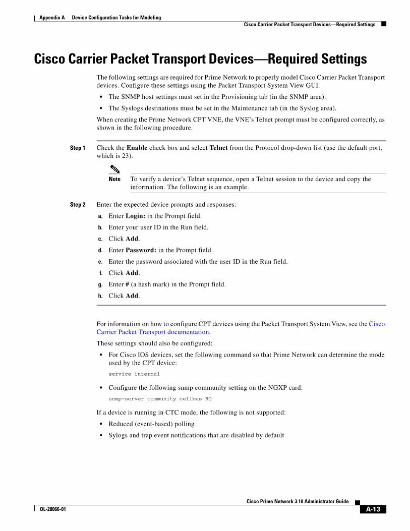
A-13Cisco Prime Network 3.10 Administrator Guide
OL-28066-01
Appendix A Device Configuration Tasks for Modeling Cisco Carrier Packet Transport Devices—Required Settings
Cisco Carrier Packet Transport Devices—Required SettingsThe following settings are required for Prime Network to properly model Cisco Carrier Packet Transport devices. Configure these settings using the Packet Transport System View GUI.
• The SNMP host settings must set in the Provisioning tab (in the SNMP area).
• The Syslogs destinations must be set in the Maintenance tab (in the Syslog area).
When creating the Prime Network CPT VNE, the VNE’s Telnet prompt must be configured correctly, as shown in the following procedure.
Step 1 Check the Enable check box and select Telnet from the Protocol drop-down list (use the default port, which is 23).
Note To verify a device’s Telnet sequence, open a Telnet session to the device and copy the information. The following is an example.
Step 2 Enter the expected device prompts and responses:
a. Enter Login: in the Prompt field.
b. Enter your user ID in the Run field.
c. Click Add.
d. Enter Password: in the Prompt field.
e. Enter the password associated with the user ID in the Run field.
f. Click Add.
g. Enter # (a hash mark) in the Prompt field.
h. Click Add.
For information on how to configure CPT devices using the Packet Transport System View, see the Cisco Carrier Packet Transport documentation.
These settings should also be configured:
• For Cisco IOS devices, set the following command so that Prime Network can determine the mode used by the CPT device:
service internal
• Configure the following snmp community setting on the NGXP card:
snmp-server community cellbus RO
If a device is running in CTC mode, the following is not supported:
• Reduced (event-based) polling
• Sylogs and trap event notifications that are disabled by default
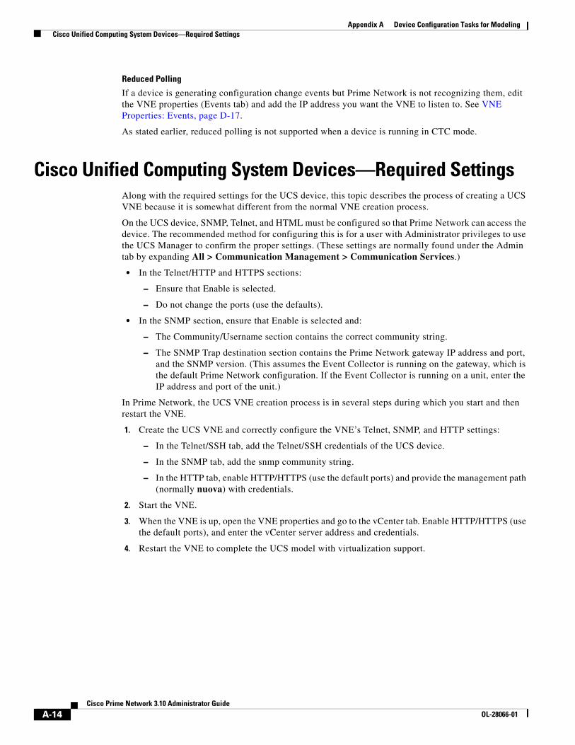
A-14Cisco Prime Network 3.10 Administrator Guide
OL-28066-01
Appendix A Device Configuration Tasks for Modeling Cisco Unified Computing System Devices—Required Settings
Reduced Polling
If a device is generating configuration change events but Prime Network is not recognizing them, edit the VNE properties (Events tab) and add the IP address you want the VNE to listen to. See VNE Properties: Events, page D-17.
As stated earlier, reduced polling is not supported when a device is running in CTC mode.
Cisco Unified Computing System Devices—Required SettingsAlong with the required settings for the UCS device, this topic describes the process of creating a UCS VNE because it is somewhat different from the normal VNE creation process.
On the UCS device, SNMP, Telnet, and HTML must be configured so that Prime Network can access the device. The recommended method for configuring this is for a user with Administrator privileges to use the UCS Manager to confirm the proper settings. (These settings are normally found under the Admin tab by expanding All > Communication Management > Communication Services.)
• In the Telnet/HTTP and HTTPS sections:
– Ensure that Enable is selected.
– Do not change the ports (use the defaults).
• In the SNMP section, ensure that Enable is selected and:
– The Community/Username section contains the correct community string.
– The SNMP Trap destination section contains the Prime Network gateway IP address and port, and the SNMP version. (This assumes the Event Collector is running on the gateway, which is the default Prime Network configuration. If the Event Collector is running on a unit, enter the IP address and port of the unit.)
In Prime Network, the UCS VNE creation process is in several steps during which you start and then restart the VNE.
1. Create the UCS VNE and correctly configure the VNE’s Telnet, SNMP, and HTTP settings:
– In the Telnet/SSH tab, add the Telnet/SSH credentials of the UCS device.
– In the SNMP tab, add the snmp community string.
– In the HTTP tab, enable HTTP/HTTPS (use the default ports) and provide the management path (normally nuova) with credentials.
2. Start the VNE.
3. When the VNE is up, open the VNE properties and go to the vCenter tab. Enable HTTP/HTTPS (use the default ports), and enter the vCenter server address and credentials.
4. Restart the VNE to complete the UCS model with virtualization support.
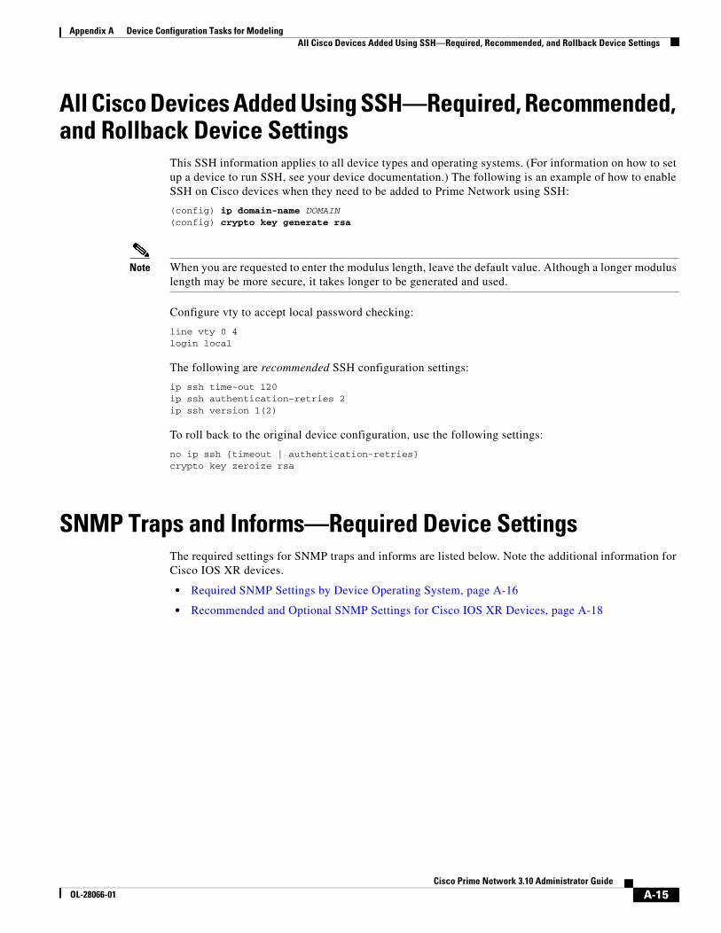
A-15Cisco Prime Network 3.10 Administrator Guide
OL-28066-01
Appendix A Device Configuration Tasks for Modeling All Cisco Devices Added Using SSH—Required, Recommended, and Rollback Device Settings
All Cisco Devices Added Using SSH—Required, Recommended, and Rollback Device Settings
This SSH information applies to all device types and operating systems. (For information on how to set up a device to run SSH, see your device documentation.) The following is an example of how to enable SSH on Cisco devices when they need to be added to Prime Network using SSH:
(config) ip domain-name DOMAIN (config) crypto key generate rsa
Note When you are requested to enter the modulus length, leave the default value. Although a longer modulus length may be more secure, it takes longer to be generated and used.
Configure vty to accept local password checking:
line vty 0 4login local
The following are recommended SSH configuration settings:
ip ssh time-out 120ip ssh authentication-retries 2ip ssh version 1(2)
To roll back to the original device configuration, use the following settings:
no ip ssh {timeout | authentication-retries}crypto key zeroize rsa
SNMP Traps and Informs—Required Device SettingsThe required settings for SNMP traps and informs are listed below. Note the additional information for Cisco IOS XR devices.
• Required SNMP Settings by Device Operating System, page A-16
• Recommended and Optional SNMP Settings for Cisco IOS XR Devices, page A-18

A-16Cisco Prime Network 3.10 Administrator Guide
OL-28066-01
Appendix A Device Configuration Tasks for Modeling SNMP Traps and Informs—Required Device Settings
Required SNMP Settings by Device Operating System
The following table lists the settings you must configure in order to properly receive SNMP traps and informs.
SNMP Type Required Setting
All snmp-server enable traps snmp authentication linkdown linkup coldstart warmstartsnmp-server enable traps chassissnmp-server enable traps modulesnmp-server enable traps bgpsnmp-server enable traps ospf state-changesnmp-server enable traps ospf errorssnmp-server enable traps ospf retransmitsnmp-server enable traps ospf lsasnmp-server enable traps ospf cisco-specific state-changesnmp-server enable traps ospf cisco-specific errorssnmp-server enable traps ospf cisco-specific retransmitsnmp-server enable traps ospf cisco-specific lsasnmp-server enable traps ipmulticastsnmp-server enable traps entitysnmp-server enable traps flash insertion removalsnmp-server enable traps envmon fan shutdown supply temperature statussnmp-server enable traps rtrsnmp-server enable traps mpls ldpsnmp-server enable traps ipsec tunnel startsnmp-server enable traps ipsec tunnel stopsnmp-server trap-source interface_name
Note interface_name is the active management IP address. This setting is required if the device has a management IP address.
Required for Nexus devices:
snmp-server enable trapssnmp-server host event_collector_IP use-vrf management-VRF
Required for StarOS devices (such as an ASR 5000; you can verify the settings using the show snmp transports command):
snmp target target-name target-IP security-name community-string version 2c traps snmp trap enable all target target-name
Required for ASR 1000:
snmp-server enable traps ipsec tunnel startsnmp-server enable traps ipsec tunnel stop
Note management-VRF is the VRF which is associated with the management IP address of the Nexus switch.
Optional for all devices:
Caution Be careful when applying the following settings. Depending on your configuration, they may result in a trap flood.
snmp-server enable traps configsnmp-server enable traps syslog

A-17Cisco Prime Network 3.10 Administrator Guide
OL-28066-01
Appendix A Device Configuration Tasks for Modeling SNMP Traps and Informs—Required Device Settings
SNMPv1 snmp-server host event_collector_IP version 1 community
SNMPv2 snmp-server host event_collector_IP {traps | informs} version 2c community
SNMPv3 With Authentication
Note MyUsr, MyGrp, MyPswd, and MyView must match the information you enter when you create the VNEs in Prime Network.
• For all devices:
snmp-server group MyGrp v3 priv write MyViewsnmp-server view MyView internet includedsnmp-server view MyView 1.2.840.10006.300 includedsnmp-server group MyGrp v3 auth [notify MyView]
• For Cisco IOS, Cisco IOS XE, and CatOS devices:
snmp-server user MyUsr MyGrp v3 auth {md5|sha} MyPswd
• For Cisco IOS XR devices:
snmp-server user MyUsr MyGrp v3 auth {md5|sha} {WORD,CLEAR,encrypted} MyPswd SystemOwner
• For all devices, after configuring SNMPv3 on the device, configure the following setting:
snmp-server host event_collector_IP traps version 3 auth MyUsr
SNMPv3 With Privacy and Authentication
Note MyUsr, MyGrp, MyAuthPswd, MyPrivPswd, and MyView must match the information you enter when you create the VNEs in Prime Network.
• For all devices:
snmp-server group MyGrp v3 priv write MyViewsnmp-server view MyView internet included snmp-server view MyView 1.2.840.10006.300 included snmp-server group MyGrp v3 priv [notify MyView]
• For Cisco IOS, Cisco IOS XE, and CatOS devices:
snmp-server user MyUsr MyGrp v3 auth {md5|sha} MyAuthPswd priv {des|aes 128|aes 192|aes 256} MyPrivPswd
• For Cisco IOS XR devices:
snmp-server user MyUsr MyGrp v3 auth {md5|sha} {WORD,CLEAR,encrypted} MyAuthPswd priv {des|aes 128|aes 192|aes 256} {WORD,CLEAR,encrypted} MyPrivPswd SystemOwner
• For all devices, after configuring SNMPv3 on the device, configure the following setting:
snmp-server host event_collector_IP traps version 3 priv MyUsr
SNMP Type Required Setting

A-18Cisco Prime Network 3.10 Administrator Guide
OL-28066-01
Appendix A Device Configuration Tasks for Modeling SNMP Traps and Informs—Required Device Settings
Recommended and Optional SNMP Settings for Cisco IOS XR Devices
In large-scale environments that contain more than 100 EFPs or PWs associated with the same interface/subinterface, an interface outage may generate a large number syslogs and traps. In such scenarios we recommended that you increase the default snmp server queue length buffer size using the following command. This applies to Cisco IOS XR 4.0 and later. The value of new-buffer-size should at least equal the number of EFP or PW objects. (This increase is also advisable if traps are being used as a transport mechanism for syslogs by way of the CISCO-SYSLOG-MIB.)
snmp-server queue-length new-buffer-size
If a Cisco IOS XR device has a configured virtual IP address and the VNE was added using that address, the device can receive the traps and syslogs through the virtual IP address. You do not need to configure the source for the SNMP traps and syslogs in the Prime Network Administration GUI client, as described in VNE Properties: Events, page D-17. The following are examples of commands for configuring a virtual IP address:
ipv4 virtual address 10.49.224.120 255.255.255.128ipv4 virtual address use-as-src-addr
SNMPv3 No Authentication
Note MyNoAuthUsr and MyNoAuthGrp must match the information you enter when you create the VNEs in Prime Network.
• For Cisco IOS, Cisco IOS XE, and CatOS devices:
snmp-server group MyNoAuthGrp v3 noauthsnmp-server user MyNoAuthUsr MyNoAuthGrp v3
• For Cisco IOS XR devices:
snmp-server user MyNoAuthUsr MyNoAuthGrp v3 SystemOwner
• For all devices, after configuring SNMPv3 on the device, configure the following setting:
snmp-server host event_collector_IP traps version 3 noauth MyNoAuthUsr
SNMP Informs SNMP Informs can be configured for all SNMPv3 modes. The following is an example for configuring SNMPv3 Informs for the mode SNMPv3 With Privacy and Authentication. The configuration is similar for the other modes (refer to the required settings for each mode for guidelines).
Note For Informs, MyUsr corresponds to Prime Network’s local user (not the device-configured user that is used for polling and receiving traps).
• For Cisco IOS, Cisco IOS XE, and CatOS devices:
snmp-server user MyUsr MyGrp remote event_collector_IP v3 auth {md5|sha} MyAuthPswd priv {des|aes 128|aes 192|aes 256} MyPrivPswd
• For Cisco IOS XR devices:
snmp-server user MyUsr MyGrp remote event_collector_IP v3 auth {md5|sha} {WORD,CLEAR,encrypted} MyAuthPswd priv {des|aes 128|aes 192|aes 256} {WORD,CLEAR,encrypted} MyPrivPswd SystemOwner
• For all devices, after configuring SNMPv3 on the device, configure the following setting:
snmp-server host event_collector_IP informs version 3 priv MyUser
SNMP Type Required Setting

A-19Cisco Prime Network 3.10 Administrator Guide
OL-28066-01
Appendix A Device Configuration Tasks for Modeling SNMP Traps and Informs—Required Device Settings
To enable all traps to be sent from a Cisco IOS XR device:
snmp-server traps <CR>
Alternatively, choose from the following list to enable forwarding of specific traps from Cisco IOS XR devices:
snmp-server trap link ietfsnmp-server traps rfsnmp-server traps bfdsnmp-server traps ethernet cfmsnmp-server traps ds1snmp-server traps ds3snmp-server traps ntpsnmp-server traps ethernet oam eventssnmp-server traps otnsnmp-server traps copy-completesnmp-server traps snmp linkupsnmp-server traps snmp linkdownsnmp-server traps snmp coldstartsnmp-server traps snmp warmstartsnmp-server traps snmp authenticationsnmp-server traps flash removalsnmp-server traps flash insertionsnmp-server traps sonetsnmp-server traps configsnmp-server traps entitysnmp-server traps syslogsnmp-server traps systemsnmp-server traps ospf lsa lsa-maxagesnmp-server traps ospf lsa lsa-originatesnmp-server traps ospf errors bad-packetsnmp-server traps ospf errors authentication-failuresnmp-server traps ospf errors config-errorsnmp-server traps ospf errors virt-bad-packetsnmp-server traps ospf errors virt-authentication-failuresnmp-server traps ospf errors virt-config-errorsnmp-server traps ospf retransmit packetssnmp-server traps ospf retransmit virt-packetssnmp-server traps ospf state-change if-state-changesnmp-server traps ospf state-change neighbor-state-changesnmp-server traps ospf state-change virtif-state-changesnmp-server traps ospf state-change virtneighbor-state-changesnmp-server traps bridgemibsnmp-server traps isis allsnmp-server traps bgpsnmp-server traps frame-relay pvc interval 30snmp-server traps atm pvc interval 30snmp-server traps imasnmp-server traps hsrpsnmp-server traps vrrp eventssnmp-server traps vpls allsnmp-server traps vpls statussnmp-server traps vpls full-clearsnmp-server traps vpls full-raisesnmp-server traps l2vpn allsnmp-server traps l2vpn vc-upsnmp-server traps l2vpn vc-downsnmp-server traps mpls traffic-eng upsnmp-server traps mpls traffic-eng downsnmp-server traps mpls traffic-eng reroutesnmp-server traps mpls traffic-eng reoptimizesnmp-server enable traps mpls frr allsnmp-server enable traps mpls frr protected

A-20Cisco Prime Network 3.10 Administrator Guide
OL-28066-01
Appendix A Device Configuration Tasks for Modeling Syslogs—Required Device Settings
snmp-server enable traps mpls frr unprotectedsnmp-server traps mpls ldp upsnmp-server traps mpls ldp downsnmp-server traps mpls ldp thresholdsnmp-server traps mpls traffic-eng p2mp upsnmp-server traps mpls traffic-eng p2mp downsnmp-server traps rsvp allsnmp-server traps rsvp new-flowsnmp-server traps rsvp lost-flowsnmp-server enable traps mpls l3vpn allsnmp-server enable traps mpls l3vpn vrf-upsnmp-server enable traps mpls l3vpn vrf-downsnmp-server enable traps mpls l3vpn max-threshold-clearedsnmp-server enable traps mpls l3vpn max-threshold-exceededsnmp-server enable traps mpls l3vpn mid-threshold-exceededsnmp-server enable traps mpls l3vpn max-threshold-reissue-notif-time 1snmp-server traps fabric planesnmp-server traps fabric bundle linksnmp-server traps fabric bundle statesnmp-server traps sensorsnmp-server traps fru-ctrl
Syslogs—Required Device SettingsThe following table lists the settings you must configure for syslogs.
Note If you are using reduced polling, be sure the follow the requirements in this section. These settings increase the depth of syslogs that will be logged, and ensures that all syslogs are handled. If the device is using Cisco IOS XR, verify the syntax of the settings against the Cisco IOS XR documentation in case there have been changes across OS releases.If a device is generating configuration change events but Prime Network is not recognizing them, edit the VNE properties (Events tab) and add the IP address you want the VNE to listen to. See VNE Properties: Events, page D-17.
Required Settings
All logging gateway_IP
Required if the device has a management IP address (interface_name is the active management IP address):
logging source-interface interface_name

A-21Cisco Prime Network 3.10 Administrator Guide
OL-28066-01
Appendix A Device Configuration Tasks for Modeling Syslogs—Required Device Settings
Cisco CatOS, Cisco IOS, and Cisco IOS XE
logging onlogging buffered 64000 informationallogging trap informationallogging event link-status default
Required for ASR 1000 IPSec Syslogs:
crypto logging session
Required for MPLS TP-related changes:
mpls tp[no] logging events[no] logging config-change
Cisco IOS XR logging onlogging events level informationallogging alarm level informationallogging buffered <307200-125000000>
Note The range indicates the minimum of 307200 and maximum of 125000000 log messages that can be stored on the device
logging trap informationallogging events link-status software-interfaces
If you will be using Path Tracer or event correlation to mimic flows that involve bridge tables, configure the following:
l2vpn resynchronize forwarding mac-address-table location node-id
Note If devices are running an older version of Cisco IOS XR, enable the following commands to make sure Prime Network is properly notified of link status changes:
logging events link-status logicallogging events link-status physical
Nexus OS If you are using reduced polling, specify the following for each VDC that is configured in the Nexus device.
logging server gateway-IP 5 use-vrf management-VRF
If you are not using reduced polling, specify one of the following (for each VDC):
logging server gateway-IP use-vrf management-VRFlogging server gateway-IP facility use-vrf management-VRF
Note management-VRF is the VRF which is associated with the management IP address of the Nexus device.
Required Settings

A-22Cisco Prime Network 3.10 Administrator Guide
OL-28066-01
Appendix A Device Configuration Tasks for Modeling IP Address Configuration for Traps, Syslogs, and VNEs
IP Address Configuration for Traps, Syslogs, and VNEsTraps and syslogs maybe dropped if any of the VNEs managed by Prime Network are configured in such a way that the following addresses are different:
• The traps and syslogs source IP address
• The VNE IP address (entered when the VNE was created and displayed in the VNE properties)
To avoid missing any traps or syslogs, do one of the following:
• Change the device configuration so that traps and syslogs are sent using the VNE’s IP address. In addition, make sure that the source IP address matches the startup-config.
• Configure the VNE to receive traps and syslogs using a different IP address by changing the VNE Properties: Events, page D-17. Do this if a device is generating configuration change events but Prime Network is not recognizing them.
Note If your deployment has virtual entities that generate events, such as applications running on virtual machines, add the entity’s IP address in the VNE Events tab. Refer VNE Properties: Events, page D-17 for more details.

B-1Cisco Prime Network 3.10 Administrator Guide
OL-28066-01
A P P E N D I X BPrime Network Log Files
The following topics describe the logs maintained by Prime Network, and the overall logging mechanism and configurable points:
• How Prime Network Saves Log Files, page B-1
• Change Log File Behavior, page B-2
• Log Files, page B-3
How Prime Network Saves Log FilesEach Prime Network module writes a log file to its own folder within the NETWORKHOME/Main/logs folder. Log sizes are limited to 4 MB by default. When a log file reaches its maximum size, Prime Network does the following:
• Zips the log file and appends a number to the backup file.
• Starts a new log file.
In the following example, the oldest file is process.log.2.gz, and process.log is the current log file.
11:42 PM 4,481,607 process.out07:22 AM 5,120,447 process.out.1.gz03:17 AM 5,120,105 process.out.2.gz
When process.log exceeds the maximum size, the following happens:
• The contents of process.out.2.gz are moved to process.log.3.gz.
• The contents of process.out.1.gz are moved to process.log.2.gz.
• The contents of process.out are moved to process.log.1.gz.
• A new log files is started (process.log).
Prime Network saves a maximum of 10 log files for each process. When the number of backups exceeds 10, the oldest file is deleted.
You can change the maximum log file size and the maximum number of backup log files by following the procedure in Change Log File Behavior, page B-2.
For a complete list of log files, see Log Files, page B-3.

B-2Cisco Prime Network 3.10 Administrator Guide
OL-28066-01
Appendix B Prime Network Log Files Change Log File Behavior
Log Files and Server Restarts
Whenever the Prime Network server is restarted, all log files are moved to NETWORKHOME/Main/logs/old.
Prime Network saves a maximum of 3 “older” sets of log files in these directories:
NETWORKHOME/Main/logs/oldNETWORKHOME/Main/logs/olderNETWORKHOME/Main/logs/oldest
For example, if a newly-installed Prime Network gateway server has been restarted once, the following happens:
• The contents in NETWORKHOME/Main/logs are moved to NETWORKHOME/Main/logs/old.
• The latest log files are stored in NETWORKHOME/Main/logs.
If the gateway server is restarted a second time, the following happens:
• The contents in NETWORKHOME/Main/logs/older are moved to NETWORKHOME/Main/logs/oldest.
• The contents in NETWORKHOME/Main/logs/old are moved to NETWORKHOME/Main/logs/older.
• The latest log files are stored in NETWORKHOME/Main/logs.
For a complete list of log files, see Log Files, page B-3.
Change Log File BehaviorLog file behavior is managed by the settings in NETWORKHOME/Main/scripts/log.pl. To change the number of log files that are saved, or to change the maximum log size, change the following settings in log.pl:
$LASTLOGINDEX = 10; # max file index to backup.$MAXSIZE = 1024*1024*4; # max file size - hitting that size will cause rollover
You must restart the gateway server for your changes to take effect.
For a complete list of log files, see Log Files, page B-3.

B-3Cisco Prime Network 3.10 Administrator Guide
OL-28066-01
Appendix B Prime Network Log Files Log Files
Log FilesTable B-1 lists the log files that are stored on the gateway server.You can view these files using any text editor. To view a log file for the VNE Customization Builder, you must first specify a log file name using the procedure documented in the Cisco Prime Network 3.10 Customization Guide.
Table B-1 Gateway Server Log Files
Gateway Server Log File Component
Log Files Located in NETWORKHOME/Main/logs
0.out Switch Virtual Machine (handles communication with unit servers)
11.out Gateway server
25.out Event persistence
35.out Gateway server (CE service discovery)
66.out Workflow Engine
76.out Jobs scheduler
77.out Change and Configuration Management
78.out VNE topology
83.out TFTP server (Change and Configuration Management)
84.out Report manager
99.out Management Virtual Machine (unit server management)
100.out Event Collector
nnn.out User-created AVM nnn management
nnn.log.restartx AVM restart information for AVM nnn (x can be 1-5)
dmctl.log
drivers/ivne-install-log-mmddyy-hhmmss Device Package installation log (web repository or local folder)
drivers_rollback_mmddyy-hhmmss.log Device Package rollback log
drivers_backup_mmddyy-hhmmss.log Device Package backup log
emdb Logs related to embedded Oracle database
haevents.log Unit server high availability events
license_server.log License server
mvm.log System restart log
mvmcsh.log System restart log (units) (for units, indicates if files were properly copied from gateway on unit restart)
nccmDeviceMgr.log
old (directory) Logs from last session
older (directory) Logs from 2 sessions earlier
oldest (directory) Logs from 3 sessions earlier

B-4Cisco Prime Network 3.10 Administrator Guide
OL-28066-01
Appendix B Prime Network Log Files Log Files
setup_xmp_nccm.log Change and Configuration management installation log
Log Files Located in /var/adm/cisco/prime-network/logs
install-log-xxxxxxxxxx1 Prime Network installation log
uninstall-log-xxxxxxxxxx1 Prime Network uninstallation log
verbose-xxxxxxxxxx1 Prime Network installation log (verbose format)
verbose-uninstall-xxxxxxxxxx1 Prime Network uninstallation log (verbose format)
Other Log Files
NETWORKHOME/XMP_Platform/logs/ConfigArchive.log
Configuration Management log file
NETWORKHOME/XMP_Platform/logs/JobManager.log
Job Manager log file (for Change and Configuration Management jobs)
NETWORKHOME/XMP_Platform/logs/NEIM.log
Network Element Image Management log file
NETWORKHOME/XMP_Platform/logs/NccmGUI.log
Change and Configuration Management GUI client log file
NETWORKHOME/XMP_Platform/logs/Startup.log
XMP server startup log file
$ORACLE_BASE/ana_logs Prime Network embedded database log
$FLEXNET_HOME/logs Prime Network license log (Flexnet and liccontrol)
NETWORKHOME/.replication Used for ADG gateway geographical redundancy to record local and remote timestamps used by GWSync.NETWORKHOME/.replication_remote
NETWORKHOME/.replication_log Used for ADG gateway geographical redundancy to log when local and remote timestamps are more than 10 minutes apart (and a System event is generated).
NETWORKHOME/oracle_monitoring.log Used for ADG gateway geographical redundancy to provide information on the Redo-apply log from the standby server.
NETWORKHOME/Main/network-conf-xxxxxxxxxx.log1
Output of network-conf portion of installation session
NETWORKHOME/Main/ha/logs Gateway server high availability
NETWORKHOME/Main/mvmcsh.log Used for debugging purposes
NETWORKHOME/Main/restarts.log Used for debugging purposes
/var/log/messages Used for RHCS local gateway redundancy
1. xxxxxxxxxx is a random unique identifier.
Table B-1 Gateway Server Log Files (continued)
Gateway Server Log File Component

B-5Cisco Prime Network 3.10 Administrator Guide
OL-28066-01
Appendix B Prime Network Log Files Log Files

B-6Cisco Prime Network 3.10 Administrator Guide
OL-28066-01
Appendix B Prime Network Log Files Log Files

C-1Cisco Prime Network 3.10 Administrator Guide
OL-28066-01
A P P E N D I X CManage the Prime Network Registry
The following topics provide an introduction to the Prime Network registry and common settings you may want to change:
• Overview of the Prime Network Registry, page C-1
• Changing Registry Settings Using runRegTool.sh, page C-2
Overview of the Prime Network Registry
The Prime Network registry is a collection of xml files (called hives) that comprise and control the Prime Network system configuration. The registry contains almost all definitions and configurations used by Prime Network. A copy of the registry is located on the gateway server and every unit in the following location:
NETWORKHOME/Main/registry/
Registry files are made up of key names and entry names. The following file fragment shows some key and entry names in the pollinggroups.xml registry file:
<key name="pollinggroups"> <key name="default"> <key name="buffering"> <entry name="interval">190000</entry> </key> <key name="configuration"> <entry name="interval">900000</entry> </key> </key></key>
In this example, the registry key path for the buffering interval would be:
pollinggroups/default/buffering/interval
where pollinggroups is the name of the hive, default is a subkey of the root key, buffering is a subkey of buffering, and so forth.
The registry files on the gateway server and units are replicas of the Golden Source registry. The Golden Source registry is the master registry that is responsible for maintaining, distributing, and updating registry configuration files to all units and the gateway server. The Golden Source registry is centrally located on the gateway server. Whenever a unit or gateway restarts, it accesses the Golden Source registry to retrieve any updates to the configuration. If a unit cannot connect to the gateway, it uses its local copy of the registry files.
The master copy of the Golden Source files is centrally located on the gateway server at:
NETWORKHOME/Main/registry/ConfigurationFiles

C-2Cisco Prime Network 3.10 Administrator Guide
OL-28066-01
Appendix C Manage the Prime Network Registry
The contents are:
The subfolders are created during the installation procedure. Each subfolder contains the relevant registry .xml files. These files can be edited as described in Changing Registry Settings Using runRegTool.sh, page C-2.
All Golden Source subdirectories contain a file called site.xml. This file contains registry settings that have been changed. When the system restarts, these settings are copied to (and override) all other Golden Source directories. For this reason, it is important to make change to site.xml so that in case of restart, your changes are not overwritten by the system defaults. Every key and entry in the Golden Source can be overridden by an entry in site.xml.
The Golden Source mechanism enables consistent management of the entire system. Each unit and gateway has its own set of registry configuration files and parameters. The registry files are replicated automatically during the installation of the unit and gateway.
Each time a unit and gateway process starts, it accesses the Golden Source and retrieves the updated configuration. All additions and changes to the Golden Source are automatically sent to the relevant units servers. Each unit keeps a local copy of its relevant registry files. When a unit cannot connect to the gateway, the unit’s local copy of the registry is used.
Changing Registry Settings Using runRegTool.sh
Note Changes to the registry should only be carried out with the support of Cisco. For details, contact your Cisco account representative.
You can change registry settings using the runRegTool.sh script, which is located in NETWORKHOME/Main, using the following command format:
runRegTool.sh -gs hostname-IP command unit-IP key [value]
Subdirectory Description
/0.0.0.0 Template directory, which is used by the system. This directory on the gateway server is the Golden Source registry.
/127.0.0.1 Gateway directory
/unit-IP-address Unit directory (one for each unit)

C-3Cisco Prime Network 3.10 Administrator Guide
OL-28066-01
Appendix C Manage the Prime Network Registry
The runRegTool.sh script takes the following options.
Note Registry changes should be made to the site.xml file, except for changes being made to AVM XML files. Therefore, your command syntax should always include site as the first part of the key name (this is not required for get or list commands):
Argument/Option Description
-gs Performs a registry command using the Golden Source.
hostname-IP IP address of the gateway server or unit server where the golden source is located. In most cases the golden source is on the gateway server; you can use the gateway IP address or the address 127.0.0.1.
command The runRegTool.sh script registry command:
• set—Sets a registry key named key to a new value of value
• setEncrypted—Sets and encrypts the registry key named key to value
• unset—Returns a registry key named key to its default value
• add—Adds a new registry key named key with a value of value
• remove—Deletes a registry key named key
• list—Lists all registry keys under a given key
• get—Retrieves the value of a registry key named key
unit-IP IP address of the destination to which the changes should be written, according to these guidelines:
• Gateway server changes (hostname-ip is the gateway server):
– Use unit-IP 127.0.0.1 for get commands.
– Use unit-IP 127.0.0.1 for all commands on AVMs (reserved AVMs or user-created AVMs).
– Use unit-IP 0.0.0.0 for all other command instances.
• Unit server changes (for example, an AVM on a unit), unit-IP should be the unit IP address.
key Registry entry name consisting of the XML file name, the key name(s), and entry.
• For all user-created AVMs, use this format, where avmxxx is the AVM on which the VNE resides, and vne-key is the VNE name used by Prime Network. The site/ prefix is not required for reserved AVMs.
avmxxx/agents/da/vne-key/...
• For all other registry keys, precede the key string with site/ so that changes are made to (or values are checked against) the local site.xml file:
site/key
value The new value for the registry entry.

C-4Cisco Prime Network 3.10 Administrator Guide
OL-28066-01
Appendix C Manage the Prime Network Registry
The following are some examples of how to use the runRegTool.sh script:
• This get command returns the current settings for all polling groups on the unit with the IP address unit-IP. It uses the site/ prefix in case any changes have already been configured:
# ./runRegTool.sh -gs hostname-IP get unit-IP site/pollinggroups
• This set command configures the LDP Neighbor Down event to not persist its alarm information. Note that site precedes the key so that change are made locally:
# ./runRegTool.sh -gs gateway-IP set unit-IP "site/event-persistency-application/events/LDP neighbor loss/sub-types/LDP neighbor down/alarm-persistency" unpersist
• This get command returns the current adaptive polling settings for a VNE with the ID CRS1-local, that runs on AVM 521. Because the change is made to a user-created VNE, the key is not preceded with site.
# ./runRegTool.sh -gs hostname-IP get unit-IP "avm521/agents/da/CRS1-local/dcs/type/com.sheer.metrocentral.coretech.common.dc.ManagedElement/adaptivePolling”

D-1Cisco Prime Network 3.10 Administrator Guide
OL-28066-01
A P P E N D I X DVNE Properties Reference
The following tables provide a list of all VNE properties. The tabs that are listed depend on the device type—for example, the vCenter tab is displayed only for Cisco Unified Computing System devices.
Step 1 Expand the All Servers branch, then select the required AVM in the navigation tree.
Step 2 Open the VNE Properties dialog box by right-clicking the required VNE in the VNE Properties table, then choose Properties.
VNE Tab Description Described in:
General Contains general information such as VNE name, IP address, and scheme. By default, Prime Network uses the newest DP installed on the gateway or unit. If you are creating a single VNE, you can specify a different DP from the drop-down list.
Note If Prime Network is installed with Cisco Prime Central, be sure to use a device’s SYSNAME as its VNE name. This allows the device to be recognized across the common inventory.
VNE Properties: General, page D-2
SNMP Specifies SNMP information and credentials to support polling and device reachability. The fields displayed in the dialog box depend on the protocol you select.
VNE Properties: SNMP, page D-5
Telnet/SSH Enables Telnet and SSH for device reachability and investigation, including the Telnet sequence and SSH prompts. The fields displayed in the dialog box depend on the protocol you select.
VNE Properties: Telnet/SSH, page D-6
XML Enables XML for device reachability and investigation. VNE Properties: XML, page D-12
HTTP Enables HTTP or HTTPS for device reachability and investigation.
VNE Properties: HTTP, page D-13
TL1 Enables the TL1 management protocol for running scripts on the device (used by Change and Configuration Management only).
VNE Properties: TL1, page D-14
ICMP Enables ICMP and the ICMP polling rate (in seconds) for device reachability testing.
VNE Properties: ICMP, page D-13

D-2Cisco Prime Network 3.10 Administrator Guide
OL-28066-01
Appendix D VNE Properties Reference VNE Properties: General
To edit VNE properties, see Change a VNE IP Address and Other VNE Properties, page 4-33.
VNE Properties: GeneralTo view a VNE’s General properties, right-click the VNE in the Servers drawer and select Properties. By default it opens to the General tab. Table D-1 describes the fields in the VNE General properties dialog box.
Polling Associates a VNE with a previously created polling group or allows you to configure different polling settings according to the type of VNE information you want (status, configuration, and so forth).
VNE Properties: Polling, page D-14
Adaptive Polling
Controls how the VNE responds to high CPU situations. VNE Properties: Adaptive Polling, page D-16
Events Specifies other IP addresses on which the VNE should listen for syslogs and traps.
VNE Properties: Events, page D-17
vCenter Enables connections to a Cisco UCS vCenter server using the HTTP or HTTPS communication protocol for vCenter reachability and investigation. (This tab appears after you add a UCS VNE.)
VNE Properties: vCenter, page D-18
VNE Tab Description Described in:
Table D-1 Fields in the VNE General Tab
Field Description
Identification Area
Name Name of the VNE, which will be used as a unique key in Prime Network. It is also used for commands that manipulate the VNE.
Note If Prime Network is installed with Cisco Prime Central, be sure to use a device’s SYSNAME as its VNE name. This allows the device to be recognized across the common inventory.
You cannot change a VNE name once you have created the VNE. To change the name you must delete and add a new VNE.
IP Address Device management IP address of the network element. You can change the IP address of an existing VNE by changing it in this field. You must stop and restart the VNE to apply your change.

D-3Cisco Prime Network 3.10 Administrator Guide
OL-28066-01
Appendix D VNE Properties Reference VNE Properties: General
Type Defines the protocol Prime Network will use to model the element, and the extent to which you want the element to be modeled. For information on how Prime Network responds when an NE is unreachable, see Change Settings That Determine Device Reachability, page 12-23. In the drop-down list, choose the VNE device type:
• Auto Detect—Use this type if SNMP is enabled on the element. Prime Network will use SNMP to gather all available inventory information.
• Generic SNMP—Use this type if SNMP is enabled on the element, and either Prime Network does not support the element, or Prime Network does support the element but you only want basic information to be modeled. Prime Network will use SNMP to gather the most basic inventory information that is normally provided by all network elements. See Notes on Generic SNMP VNEs, page D-4.
• Cloud—Use this type for an unmanaged network segment. Specific Cloud configuration is provided on a per-project basis. All other tabs will be disabled. See Create Connections for Unmanaged Network Segments (Cloud VNEs and Links), page 12-42.
• ICMP—Use this type if ICMP is enabled on the element, and either Prime Network does not support the element, or Prime Network does support the element but you only want basic information to be modeled. Prime Network will use ICMP to gather the most basic inventory information that is normally provided by all network elements, and will perform reachability testing only. ICMP VNEs can connect to other VNEs using static links. If you want to connect ICMP VNEs using physical links, you must configure the ICMP VNE’s MAC address, as described in Notes on ICMP VNEs, page D-13.
Scheme Defines the VNE modeling components investigated during the discovery process and then populated in the VNE model. This enables the administrator to define different behavior for some network elements; for example, some network elements poll only with SNMP, and other network elements poll with Telnet. Soft properties and activation scripts are also attached to a specific scheme. By default, the VNE inherits the VNE scheme from the default scheme. Where more than one scheme exists in the network, the VNE loads the selected scheme.
• Product— For devices that are not part of the network core, such as the Cisco 800 Series or 2900 Series.
• IpCore—For devices that are part of the network core, such as the Cisco 3600 Series, 12000 GSR (Gigabit Switch Router) Series, or CRS (Carrier Routing System) Series.
• EMS—For devices where only system information and physical inventory should be polled (that is, the minimum amount of data). It is supported on all devices but does not support any technologies.
• Default—For cases where you are not sure which scheme to choose. Prime Network will use the Product scheme.
For more information, see Choosing a VNE Scheme (Check Technologies and Device Types), page A-2.
Table D-1 Fields in the VNE General Tab (continued)
Field Description

D-4Cisco Prime Network 3.10 Administrator Guide
OL-28066-01
Appendix D VNE Properties Reference VNE Properties: General
Notes on Generic SNMP VNEs
The generic SNMP VNE is a VNE that is not related to any vendor, can represent any vendor (with certain limitations), and provides lightweight management support for network devices. A generic SNMP VNE does the following:
• Provides basic management capabilities for a device with the following technologies:
– IP (restricted to basic IP only; does not include modeling of IPsec, MPLS, or routing protocols)
– Ethernet switching
– 802.1q
• Supports these inventory items:
– Physical inventory (specific port types only)
– Routing table
– ARP table
– Default bridge
– IP interfaces
Initial State Area
State Sets the initial disposition of the VNE. Normally you should set it to Stop, especially if you want to verify the VNE configuration, or if you know the VNE is very complex and might need extra processing to complete the loading procedure.
Note If you use auto-add, the VNE will automatically be started.
• Stop—The VNE is not loaded. This is the default state.
• Start—The VNE is loaded and starts collecting data.
To move an existing VNE to the maintenance state, see Stop, Start, and Move VNEs to Maintenance Mode, page 4-9.
VNE Location
Unit IP address of the unit that hosts the AVM for the VNE.
AVM AVM ID associated with this VNE.
VNE Driver Details
Version (Existing VNEs only) Version of the VNE device driver being used.
Device Package Name
For existing VNEs, this is the Device Package that is installed on the gateway server. You can use this and the driver file name information to verify whether a newer driver is available, which might supply additional functionality. See Find Out if New Device Support is Available, page 4-27.
For new VNEs, this is a drop-down list that displays all available Device Packages. By default, the VNE uses the latest DP that is installed on the gateway or unit. After creating the VNE, you can update it to use new driver files as described in Change the Device Package a VNE Is Using, page 4-30.
Driver File Name
(Existing VNEs only) Name of the VNE device driver being used (this driver corresponds to the DP that is listed).
Table D-1 Fields in the VNE General Tab (continued)
Field Description

D-5Cisco Prime Network 3.10 Administrator Guide
OL-28066-01
Appendix D VNE Properties Reference VNE Properties: SNMP
• Supports these topologies:
– Physical Layer Connectivity
– MAC-based ethernet topologies
If a VNE is identified as unsupported (because its type was not recognized), Prime Network gives the VNE a status of Unsupported. You can either leave the VNE as Unsupported or load it as a Generic SNMP VNE.
Every VNE in agentdefaults/da has the entry “load generic agent for unsupported device type,” where you can set the value as true or false (the default). If the value is true, it sets 1.3.999.3 as the property. It looks for this property in agentdefaults/da/deviceTypes and finds sheer/genericda. It then skips the investigation of the device software versions and builds the VNE (generic SNMP) from the default version.
VNE Properties: SNMPTo view a VNE’s SNMP settings, right-click the VNE in the Servers drawer and select Properties, and click the SNMP tab. Table D-2 describes the fields in the VNE SNMP properties dialog box.
Table D-2 Fields in the VNE SNMP Tab
Field Description
SNMP Version Area
Enable SNMP If checked, enables the SNMP communication protocol so that the user can work with it. A VNE can have SNMP enabled or disabled at any time; however, when the Auto Detect check box is checked (in the General tab), it cannot be disabled.
SNMP V1/V2 Settings (activated using SNMP V1 or SNMP V2)
SNMP V1 and V2 fields are available only when SNMP is enabled.
Read SNMP read community status, public (default) or private, as defined by the user.
Write (Optional) SNMP write community status, public or private (default), as defined by the user.
SNMP V3 Settings (activated if using SNMP V3)
SNMP V3 fields are available only when SNMP V3 is chosen. Make sure you have performed the required SNMPv3 device configuration tasks listed in SNMP Traps and Informs—Required Device Settings, page A-15.
Authentication Type of authentication to be used:
• No—Authentication is not required (default).
• md5—Uses Message Digest 5 (MD5) for the authentication mechanism.
• sha—Uses Secure Hash Algorithm (SHA) for the authentication mechanism.
User Authentication username.
Password Authentication password. This field is enabled if you choose md5 or sha.

D-6Cisco Prime Network 3.10 Administrator Guide
OL-28066-01
Appendix D VNE Properties Reference VNE Properties: Telnet/SSH
VNE Properties: Telnet/SSHTo view a VNE’s Telnet/SSH settings, right-click the VNE in the Servers drawer and select Properties, and click the Telnet/SSH tab.
You can find out if a VNE is using Telnet or SSH (along with the specific version) by opening the device properties window and click VNE Status. The VNE Status Details window provides details about the protocols. (You can open the device properties window from both Prime Network Administration (right-click the VNE and choose Inventory) and Prime Network Vision (right-click the device and choose Inventory.)
Table D-3 describes the fields in the VNE Telnet/SSH properties dialog box.
For examples of how to enter Telnet or SSH prompt information, see Telnet and SSH Login Sequences: Notes and Examples, page D-9. For more information on SSHv2 host key algorithms, also see Notes on SSHv2 Public Key and Private Key File Formats, page D-11.
Encryption Type of encryption method to be used. These choices are disabled if you choose No authentication.
• No—Encryption is not required (default).
• des—Uses Data Encryption Standard (DES) for encryption.
• aes128—Uses 128-bit Advanced Encryption Standard (AES) for authentication.
• aes192—Uses 192-bit AES for authentication.
• aes256—Uses 256-bit AES for authentication.
Password Encryption password. This field is enabled if you choose des, aes128, aes192, or aes256 encryption.
Table D-2 Fields in the VNE SNMP Tab (continued)
Field Description
Table D-3 Fields in the VNE Telnet/SSH Tab
Field Description
Enable Enables the communication protocol so Prime Network will investigate the network element. Checking this check box activates the other fields in this tab.
Protocol Type of protocol to be used: Telnet (default), SSHv1, or SSHv2.
Note By default, when a VNE opens a Telnet session with a network element in order to model and monitor the element, the Telnet session remains open for 5 minutes, even if the VNE is idle (did not query the device during the session). After 5 minutes, the VNE closes the session and reopens it when it needs to query the device. If you would like to change this configuration, contact your Cisco account representative.
Port Port the protocol will use. This field is prepopulated depending on your protocol choice. If you are not using the default port, enter the appropriate port number.
• 23—Default port for Telnet.
• 22—Default port for SSHv1 or SSHv2.
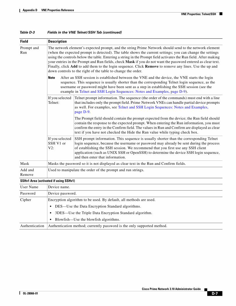
D-7Cisco Prime Network 3.10 Administrator Guide
OL-28066-01
Appendix D VNE Properties Reference VNE Properties: Telnet/SSH
Prompt and Run
The network element’s expected prompt, and the string Prime Network should send to the network element (when the expected prompt is detected). The table shows the current settings; you can change the settings using the controls below the table. Entering a string in the Prompt field activates the Run field. After making your entries in the Prompt and Run fields, check Mask if you do not want the password entered as clear text. Finally, click Add to add them to the login sequence. Click Remove to remove any lines. Use the up and down controls to the right of the table to change the order.
Note After an SSH session is established between the VNE and the device, the VNE starts the login sequence. This sequence is usually shorter than the corresponding Telnet login sequence, as the username or password might have been sent as a step in establishing the SSH session (see the example in Telnet and SSH Login Sequences: Notes and Examples, page D-9).
If you selected Telnet:
Telnet prompt information. The sequence (the order of the commands) must end with a line that includes only the prompt field. Prime Network VNEs can handle partial device prompts as well. For examples, see Telnet and SSH Login Sequences: Notes and Examples, page D-9.
The Prompt field should contain the prompt expected from the device; the Run field should contain the response to the expected prompt. When entering the Run information, you must confirm the entry in the Confirm field. The values in Run and Confirm are displayed as clear text if you have not checked the Hide the Run value while typing check box.
If you selected SSH V1 or V2:
SSH prompt information. This sequence is usually shorter than the corresponding Telnet login sequence, because the username or password may already be sent during the process of establishing the SSH session. We recommend that you first use any SSH client application (such as UNIX SSH or OpenSSH) to determine the device SSH login sequence, and then enter that information.
Mask Masks the password so it is not displayed as clear text in the Run and Confirm fields.
Add and Remove
Used to manipulate the order of the prompt and run strings.
SSHv1 Area (activated if using SSHv1)
User Name Device name.
Password Device password.
Cipher Encryption algorithm to be used. By default, all methods are used.
• DES—Use the Data Encryption Standard algorithms.
• 3DES—Use the Triple Data Encryption Standard algorithm.
• Blowfish—Use the blowfish algorithms.
Authentication Authentication method; currently password is the only supported method.
Table D-3 Fields in the VNE Telnet/SSH Tab (continued)
Field Description

D-8Cisco Prime Network 3.10 Administrator Guide
OL-28066-01
Appendix D VNE Properties Reference VNE Properties: Telnet/SSH
SSHv2 Area (activated if using SSHv2)
User Name SSHv2 username.
Client Authentication
Client-driven authentication method to be used.
password Use a password to authenticate the client. Enter the password in the Password field.
public-key Optionally, use public key authentication, which uses a key pair system in which the client application is configured with the secret private key, and the device is configured with the public (non-secret) key (of this pair). To create a pair of keys:
1. In the Private Key field, click . . . to import the private key from a file. You cannot manually enter they key, but you can edit a key that you import from file. If you change it to the wrong key, you will see an error message.
2. In the Public Key area, generate the public key in any of the following ways:
– Click . . . to import the public key from a file.
– Manually enter a public key.
– Click Generate to autogenerate a public key.
Server Authentication
Server authentication method to be used.
none No server authentication. (This method does not do any authentication and is not recommended, because it poses a security risk for “man-in-the-middle” attacks.)
save-first-auth
Uses the public key that was used for the first connection attempt with the server. This method assumes the first connection was legitimate. (A security risk exists if the connection was compromised.) After the first connection, the server authentication method is changed to preconfigured, and the public key data is inserted as the preconfigured data.
preconfigured Uses the server public key or fingerprint that was configured in the application event before the first connection was attempted. This is the default and is the recommended method. Selecting this method activates the Finger Print or Public Key field.
Select one of the following (and be sure to read the description, provided later in this table, of the Host Key Algorithm field):
• Finger Print—Uses a short checksum of the server public key (this serves the same purpose, but is much shorter).
• Public Key—Uses the public key in one of the permitted formats (see Notes on SSHv2 Public Key and Private Key File Formats, page D-11). Click . . . to import the public key from a file.
By default, the SSHv2 Key, MAC, ciphers, and host key algorithms1 are allowed (enabled):
• Key exchange: DH-group1-sha1, DH-group1-exchange-sha1
• MAC algorithm: SHA1, MD5, SHA1-96, MD5-96
• Ciphers: 3DES, AES-128, AES-192, AES-256, Blowfish, Arcfour
• Host Key Algorithm: DSA, RSA
For information on how to change these settings, see Communication Security with Devices: SSH and SNMPv3, page 11-5.
1. You can select multiple algorithms by pressing Ctrl while choosing a method. If more than one is selected, the application will try to use all of the algorithms until one is accepted by the server. There is no priority in the way the algorithms are tried.
Table D-3 Fields in the VNE Telnet/SSH Tab (continued)
Field Description

D-9Cisco Prime Network 3.10 Administrator Guide
OL-28066-01
Appendix D VNE Properties Reference VNE Properties: Telnet/SSH
Telnet and SSH Login Sequences: Notes and Examples
When you add a VNE, Prime Network uses the specified communication protocol to connect to the network element and gather modeling and status information. You must provide the information Prime Network will need: the characters and order of the network element’s expected prompts, and the string Prime Network should send to the network element in response (so that you can get to enable mode for Cisco IOS and Cisco IOS XE devices, and XML mode for Cisco IOS XR devices).
Before creating the login sequences, check for device-specific prerequisites and other details in Device Configuration Tasks for Modeling, page A-1.
Note VNEs can understand partial and complete device prompts.
After an SSH session is established between the VNE and the device, the VNE starts the SSH login sequence. This sequence is usually shorter than the corresponding Telnet login sequence.
This topic provides two examples (with complete procedures) that show how to enter Telnet sequences:
• Telnet Login Sequence for a Cisco IOS Device: Example, page D-9
• Telnet Sequence for a Cisco IOS XR Device: Example, page D-10
A Telnet sequence (the order of the commands) must end with a line that includes only the enable prompt (for Cisco IOS and Cisco IOS XE devices) or the router CLI prompt (for Cisco IOS XR devices). Not all device families will have the same Telnet sequence; this is especially true for Cisco IOS devices. For RAD ACE-2300 devices, because SNMP is used for device modeling, we recommend disabling Telnet to avoid unnecessary queries.
Telnet Login Sequence for a Cisco IOS Device: Example
This sample procedure describes how you could enter a Telnet sequence for a hypothetical Cisco IOS device or Cisco IOS XE device.
Step 1 Check the Enable check box to activate the Telnet prompt fields.
Step 2 Enter the expected device prompt and response:
Note To verify a device’s Telnet sequence, open a Telnet session to the device and copy the information. The following is an example.
a. Enter Password: in the Prompt field.
Note If you do not want the password displayed in clear text, check Mask.
b. Enter Rivers39* in the Run field.
c. Click Add.
Step 3 Enter the device prompt and the command required to place the device in enable mode:
a. Enter R3745> in the Prompt field.
b. Enter enable in the Run field.
c. Click Add.

D-10Cisco Prime Network 3.10 Administrator Guide
OL-28066-01
Appendix D VNE Properties Reference VNE Properties: Telnet/SSH
Step 4 Enter the enable mode password information:
a. Enter Password: in the Prompt field.
Note If you do not want the password displayed in clear text, check Mask.
b. Enter !Tribal41_ in the Run field.
c. Click Add.
Step 5 Enter the enable prompt information:
a. Enter R3745# in the Prompt field.
Note VNEs can also understand partial prompts. For example, if you enter the string # instead of R3745#, the VNE will still be able to recognize the expected prompt.
Leave the Run field blank.
b. Click Add.
Telnet Sequence for a Cisco IOS XR Device: Example
This sample procedure describes how you could enter a Telnet sequence for a hypothetical Cisco IOS XR device.
Step 1 Check the Enable check box to activate the Telnet prompt fields.
Step 2 Enter the expected device prompt and response:
Note To verify a device’s Telnet sequence, open a Telnet session to the device and copy the information. The following is an example.
a. Enter Username: in the Prompt field.
b. Enter crs1-oak in the Run field.
c. Click Add.
Step 3 Enter the device password information:
Note Enter Password: in the Prompt field.
Note If you do not want the password displayed in clear text, check Mask.
d. Enter sunFlower108! in the Run field.
e. Click Add.

D-11Cisco Prime Network 3.10 Administrator Guide
OL-28066-01
Appendix D VNE Properties Reference VNE Properties: Telnet/SSH
Step 4 Enter the device prompt:
a. Enter EC-A# in the Prompt field.
Note For devices with multiple processors (such as Cisco CRS), the prompt comprises the active CPU plus the device name (for example, RP/0/RSP0/CPU0:EC-A#). A CPU failover could change the prompt and report a different CPU. In these cases, you should insert a prompt that specifies only the device name (for example, EC-A#). (Also, as with Cisco IOS, VNEs can also understand partial prompts. For example, if you enter the string # instead of EC-A#, the VNE will still be able to recognize the expected prompt.)
Leave the Run field blank.
b. Click Add.
Notes on SSHv2 Public Key and Private Key File Formats
There are several file formats for public and private RSA and DSA keys. The same key can be written differently according to the format that is used.
This application officially supports the openSSH format. For more details, see http://www.openssh.com/manual.html.
Make sure that the keys you provide as input parameters are in this format. If they are not, you need to convert them to the open SSH format before applying them.
Use Case Example: When working with Cisco IOS, the public key is retrieved using the show crypto key mypubkey command. This format is not compatible with the OpenSSH format, and is not supported. There are several ways to convert the format.
The easiest solution is to use public key scan by the (free) openSSH application to retrieve the public key in the supported format. For more details, see http://www.openssh.com/manual.html.
Another option is to convert the files to the required format either manually or by using a script.
The following are examples of valid file formats.
RSA- private key -----BEGIN RSA PRIVATE KEY-----MIICWwIBAAKBgQDvdpW8ItfbSp/hTbWZJqCPmjRyh9S+EpTJ0Aq3fnGpFPTR+……..TiOfhiuX5+M1cTaE/if8sScj6jE9A0MpShBrnDU/0A==-----END RSA PRIVATE KEY-----
DSA private key-----BEGIN DSA PRIVATE KEY-----MIIBuwIBAAKBgQDNGO+l2XW+W+YtVnWSYbKXr6qkrH9nOl+………7wO4+FR9afoRjDusrQrL-----END DSA PRIVATE KEY-----
DSA public keyssh-dss AAAAB3………HfuNYu+ DdGY7njEYrN++iWs= aslehr@aslehr-wxp01
RSA - public keyssh-rsa AAAAB3…lot more…qc8Hc= aslehr@aslehr-wxp01

D-12Cisco Prime Network 3.10 Administrator Guide
OL-28066-01
Appendix D VNE Properties Reference VNE Properties: XML
VNE Properties: XMLTo view a VNE’s XML properties, right-click the VNE in the Servers drawer and select Properties and click the XML tab. XML is used by some devices such as those that use Cisco IOS XR. Table D-4 describes the fields in the VNE XML properties dialog box.
Table D-4 Fields in the VNE XML Tab
Field Description
Enable Enables the XML communication protocol so Prime Network will investigate the network element. Checking this check box activates the other fields in this tab.
Protocol Type of protocol to be used: Telnet (default) or SSL.
Note By default, when a VNE opens a Telnet session with a network element in order to model and monitor the element, the Telnet session remains open for 5 minutes, even if the VNE is idle (did not query the device during the session). After 5 minutes, the VNE closes the session and reopens it when it needs to query the device. If you would like to change this configuration, contact your Cisco account representative.
Port Port the protocol will use. This field is prepopulated depending on your protocol choice. If you are not using the default port, enter the appropriate port number.
• 38751—Default port for Telnet.
• 38752—Default port for SSL.
Prompt and Run
The network element’s expected Telnet or SSL prompt, and the string Prime Network should send to the network element (when the expected prompt is detected). The table shows the current settings; you can change the settings using the controls below the table. Entering a string in the Prompt field activates the Run field. After making your entries in the Prompt and Run fields, check Mask if you do not want the password entered as clear text. Finally, click Add to add them to the login sequence. Click Remove to remove any lines. Use the up and down controls to the right of the table to change the order.
Note After an SSH session is established between the VNE and the device, the VNE starts the login sequence. This sequence is usually shorter than the corresponding Telnet login sequence, as the username or password might have been sent as a step in establishing the SSH session (see the example in Telnet and SSH Login Sequences: Notes and Examples, page D-9).
The sequence (the order of the commands) must end with a line that includes only the prompt field. The Prompt field should contain the prompt expected from the device; the Run field should contain the response to the expected prompt. When entering the Run information, you must confirm the entry in the Confirm field. The values in Run and Confirm are displayed as clear text if you have not checked the Hide the Run value while typing check box.
Mask Masks the password so it is not displayed as clear text in the Run and Confirm fields.
Add and Remove
Used to manipulate the order of the prompt and run strings.

D-13Cisco Prime Network 3.10 Administrator Guide
OL-28066-01
Appendix D VNE Properties Reference VNE Properties: HTTP
VNE Properties: HTTPTo view a VNE’s HTTP and HTTPS settings, right-click the VNE in the Servers drawer and select Properties, and click the HTTP tab.
Table D-5 describes the fields in the VNE HTTP properties dialog box.
VNE Properties: ICMPTo view a VNE’s ICMP settings, right-click the VNE in the Servers drawer and select Properties, and click the ICMP tab. Table 4-6 describes the fields in the VNE ICMP properties dialog box.
Notes on ICMP VNEs
ICMP VNEs are used to test the reachability to a device. For ICMP VNEs, Prime Network does not poll the device to create a physical and logical inventory. But to connect the ICMP VNE to another VNE and visualize a link on the map, the ICMP VNE must have a port in its physical inventory. Therefore, when Prime Network creates an ICMP VNE, it creates a physical inventory model that contains only an Ethernet port.
You can use static links to connect ICMP VNEs to other VNEs.
Prime Network will autodiscover physical links between the ICMP VNE and other VNEs if the following conditions are met:
• The real MAC address of the port is configured for the ICMP VNE.
• The port on the ICMP VNE is a routed port and terminates the Layer 2 domain.
To specify a MAC address for an ICMP VNE, use the following procedure.
Table D-5 Fields in the VNE HTTP Tab
Field Description
Enable Enables the HTTP communication protocol so Prime Network can investigate the network element. Checking this check box activates the other fields in this tab.
Enable HTTPS Enables the secure HTTP communication protocol.
Port Port the protocol will use. By default, HTTP uses port 80, and HTTPS uses 443.
Management Path HTTP URL to use to connect the device.
Use Authentication Enables requiring credentials for HTTP to log in to the device.
Table 4-6 Fields in the VNE ICMP Tab
Field Description
Enable Instructs Prime Network to use the ICMP communication protocol to verify that the network element is reachable. You can enable or disable ICMP polling at any time by checking or unchecking the check box (except for ICMP type VNEs, which require this setting to be enabled).
Polling Rate Polling rate in seconds. If ICMP is enabled, this is a required field.

D-14Cisco Prime Network 3.10 Administrator Guide
OL-28066-01
Appendix D VNE Properties Reference VNE Properties: TL1
Step 1 Log into the gateway as pnuser and change to the Main directory by entering the following command. (pnuser is the operating system account for the Prime Network application, created when Prime Network is installed; for example, pn310.)
# cd $ANAHOME/Main
Step 2 Configure the MAC address for the VNE. For the gateway, unit-IP should be 0.0.0.0. For units, the unit-IP should be the unit’s IP address.
# ./runRegTool.sh -gs gateway-IP set unit-IP site/sheericmp/base/product/software versions/default version/spec/dcs/com.sheer.metrocentral.coretech.common.equipment.dc.Chassis/ethMacAddress mac-address
Step 3 Restart the VNE.
VNE Properties: TL1TL1 is used by the Prime Network Change and Configuration Management feature. To view a VNE’s TL1 settings, right-click the VNE in the Servers drawer and select Properties, and click the TL1 tab.
Table D-5 describes the fields in the VNE TL1 properties dialog box.
VNE Properties: PollingTo view a VNE’s Polling settings, right-click the VNE in the Servers drawer and select Properties, and click the Polling tab. This tab is disabled if you chose ICMP as the VNE type (in the General tab). In addition to controlling the intervals at which a network element is polled, this dialog box specifies the adaptive polling settings, which specify how a VNE should respond to high device CPU usage.
Note If you want to apply polling settings at a global level (rather than per VNE), create a polling group that can then be applied across VNEs. See Regular Polling (VNE Polling Groups), page 12-17.
Table D-7 Fields in the VNE TL1 Tab
Field Description
Enable Enables the TL1 management protocol for CPT devices. Checking this box activates the other fields in this tab.
Port Port the protocol will use.
User TL1 user name
Password Password for TL1 user.

D-15Cisco Prime Network 3.10 Administrator Guide
OL-28066-01
Appendix D VNE Properties Reference VNE Properties: Polling
Table D-8 describes the fields in the VNE Polling properties dialog box.
Table D-8 Fields in the VNE Polling Tab
Field Description
Polling Method
Polling approach for model updates
Specifies whether to use normal or reduced polling. The reduced polling mechanism polls a device only when a configuration change syslog is received (which results in less polling overall). You can verify whether a device supports reduced polling by clicking the Supported on selected devices only link.
By default, reduced polling is enabled. For more information see Reduced Polling, page 12-3.
Always use reduced polling
Prime Network will define the settings based on the recommended offset of model fidelity vs. interference. If the device type does not support event-based polling, Prime Network generates a Device Unsupported event.
Use this when you want to be notified if the device type does not support reduced polling.
Used reduced polling if possible
Prime Network will define the settings based on the recommended offset of model fidelity vs. interference. If the device type does not support event-based polling, Prime Network uses regular polling.
Note This is the default method for all VNEs.
Use this when you do not want to be notified if the device type does not support reduced polling.
Use regular polling
Instructs Prime Network to proactively poll configuration data using a configuration interval (usually every 15 minutes). This means that even in extreme circumstances where events are lost, the VNE would be synchronized after a maximum of 15 minutes (not 24 hours).
Use this when you want the device to use regular polling regardless of whether its device type supports reduced polling.
Polling Parameters
Group Use polling rates from one of the polling groups listed in the drop-down list. This allows you to apply polling rates more globally, to devices of similar type. By default, Prime Network uses Group (not Instance), and the polling group named default (which is provided out-of-the-box).
Note You can create new polling groups that will appear in the drop-down list by using the procedure in Regular Polling (VNE Polling Groups), page 12-17.
Instance Uses a user-specified polling rate created by changing the polling rates of any one of the built-in polling intervals displayed in the dialog box. When you select Instance, the Polling Intervals and Topology areas are activated. These settings are applied to only this VNE.
Note A polling rate that is not changed inherits its settings from the group specified in the drop-down list.
Polling Intervals Area (activated if using Instance)
Note We recommend that you use the default settings for these polling intervals. Setting the fields below the default values can result in an overload of the Prime Network unit or polled device.
Status Polling rate for status-related information, such as network element status (up or down), port status, administrative status, and so on. This is typically the most frequently polled information, reflecting the current operational and administrative state of the element and its components. The default setting is 180 seconds.
Configuration Polling rate for configuration-related information, such as VC tables, scrambling, and so on. These reflect more dynamic element configuration such as forwarding, routing, and switching tables. The default setting is 900 seconds.

D-16Cisco Prime Network 3.10 Administrator Guide
OL-28066-01
Appendix D VNE Properties Reference VNE Properties: Adaptive Polling
VNE Properties: Adaptive PollingTable D-9 describes the fields in the VNE Adaptive Polling tab.
System Polling rate for system-related information, such as network element name, network element location, and so on. These reflect element configurations that are less dynamic in nature. The default setting is 86400 seconds.
Topology Area (activated if using Instance)
Layer 1 Polling rate of the topology process as an interval for the Layer 1 counter. This is an ongoing process. The default setting is 90 seconds.
Layer 2 Polling rate of the topology process as an interval for the Layer 2 counter. This process is available on demand. The default setting is 30 seconds.
Table D-8 Fields in the VNE Polling Tab (continued)
Field Description
Table D-9 Fields in the VNE Adaptive Polling Tab
Field Description
Prime Network Settings
Uses the default settings for controlling VNE adaptive polling (see Adaptive Polling, page 12-10).
Device Type Settings
(Default) Uses the VNE adaptive polling settings specified for this device type (as delivered with Prime Network). If no setting exists for the device type, the Prime Network Settings are used.
Local Settings Overrides the default settings and uses the values specified in the Upper and Lower Threshold fields. Any values you specify here are used only for this VNE instance.
• To enter your own adaptive polling settings, click Local Settings and enter the thresholds. The changes are not applied until you check the Enable check box.
• To turn off adaptive polling for the VNE, click Local Settings and uncheck the Enable check box.
You must click Apply and restart the VNE for your changes to take effect.
Thresholds Upper Threshold
When CPU usage exceeds this value, the adaptive polling mechanism is triggered. The VNE switches to slow polling or maintenance mode.
Lower Threshold
When CPU usage drops below this value, the VNE moves to normal polling and related alarms are cleared.
Upper Tolerance
When upper threshold is crossed this number of consecutive CPU polls, move the VNE to slow polling. To be more conservative, enter a lower number.
(Using the settings in this table and in Table 12-4, this means the VNE would move to slow polling after 5 minutes.).
Lower Tolerance
When CPU utilization falls below the lower threshold for this number of consecutive polls, move the VNE to normal polling. To be more conservative, enter a higher number.
Maintenance Tolerance
When upper threshold is crossed this number of consecutive CPU polls, move the VNE to CPU-only polling. (This number will include the upper tolerance polls, which is 5 by default.)
SNMP Delay Delay (in milliseconds) between SNMP commands that are sent from the VNE to the device.
Telnet Delay Delay (in milliseconds) between Telnet commands that are sent from the VNE to the device.

D-17Cisco Prime Network 3.10 Administrator Guide
OL-28066-01
Appendix D VNE Properties Reference VNE Properties: Events
VNE Properties: Events
Note If a VNE is using reduced polling, add the event-generating IP address to the VNE’s Events tab so the VNE will listen to that address for syslogs and traps. For more information, see Turn Reduced Polling On or Off for a Single VNE, page 12-7.
The VNE Event settings configures the VNE to listen to additional IP addresses. If your deployment has virtual entities that generate events, such as applications running on virtual machines, add the entity’s IP address here. For example, if you are running Cisco Policy Manager (CPM) on a Cisco Unified Computing Server (UCS) and you want Prime Network to process the SNMP traps from the CPM application, you must configure the CPM application’s source IP address as an Event-Generating IP Address in this dialog box.
If a device components that have IP addresses that are different from the management IP address, enter them here, especially if the device driver cannot automatically detect these additional addresses.
Traps and syslogs maybe dropped if any of the VNEs managed by Prime Network are configured in such a way that the following addresses are different:
• The traps and syslogs source IP address
• The VNE IP address (entered when the VNE was created and displayed in the VNE properties)
To avoid missing any traps or syslogs, configure the VNE to receive traps and syslogs using both IP addresses. For Cisco IOS XR devices, if the device has a configured virtual IP address and the VNE was added using that address, the device can receive the traps and syslogs through the virtual IP address. You do not need to configure the source for the SNMP traps and syslogs.
Table 4-10 describes the fields in the VNE Events properties dialog box.
Enter the new address in the Enter IP Address field and click Add, and the new IP address is listed under Event-Generating IP Addresses. When the VNE is saved, it will be begin listening for events at the new IP address.
Table 4-10 Fields in the VNE Events Tab
Field Description
Enter IP Address Field in which to enter new IP address, where you want the VNE to listen for syslogs and traps.
Event-Generating IP Addresses
Existing IP addresses the VNE is already listening to, for syslogs and traps.
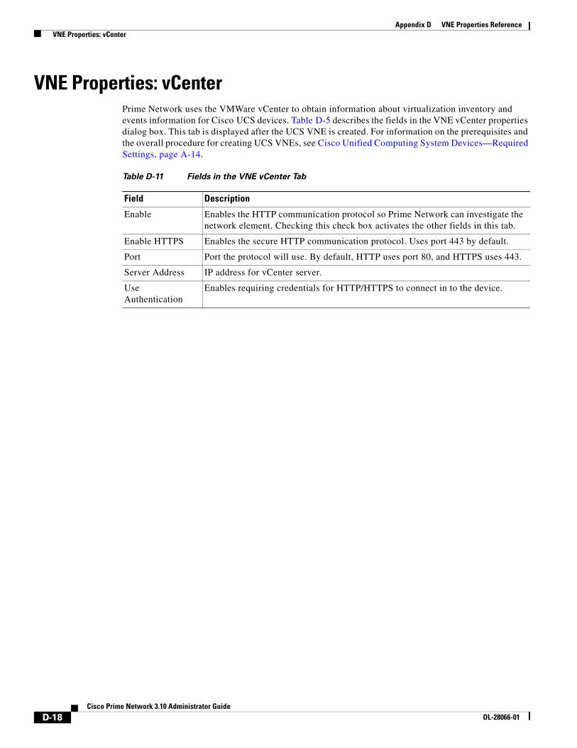
D-18Cisco Prime Network 3.10 Administrator Guide
OL-28066-01
Appendix D VNE Properties Reference VNE Properties: vCenter
VNE Properties: vCenterPrime Network uses the VMWare vCenter to obtain information about virtualization inventory and events information for Cisco UCS devices. Table D-5 describes the fields in the VNE vCenter properties dialog box. This tab is displayed after the UCS VNE is created. For information on the prerequisites and the overall procedure for creating UCS VNEs, see Cisco Unified Computing System Devices—Required Settings, page A-14.
Table D-11 Fields in the VNE vCenter Tab
Field Description
Enable Enables the HTTP communication protocol so Prime Network can investigate the network element. Checking this check box activates the other fields in this tab.
Enable HTTPS Enables the secure HTTP communication protocol. Uses port 443 by default.
Port Port the protocol will use. By default, HTTP uses port 80, and HTTPS uses 443.
Server Address IP address for vCenter server.
Use Authentication
Enables requiring credentials for HTTP/HTTPS to connect in to the device.

IN-1Cisco Prime Network 3.10 Administrator Guide
OL-28066-01
I N D E X
Numerics
6PE, 6VPE A-2
6RD A-2
A
Access List A-2
activations. See workflows and activations
Administration GUI client
installing 1-1
launching 1-1
login banner 11-12
overview 1-1
setup tasks 1-3
Administrator (user access role) 7-3
Advanced Overload Prevention
changing default behavior 8-24
configuring Global Event Filter 8-24
display current status 8-24
overview 8-23
Agent Not Loaded (VNE communication state) 4-6, 4-8, 4-43
Agent Unreachable (VNE communication state) 4-6, 4-43
alarms 8-5, 8-8
All Managed Elements (device scope) 6-2
ANAHOME 2-1, 3-4
analyze (integrity test) 8-7
AOP. See Advanced Overload Prevention
APN A-2
ARP A-3
ATM A-2
ATM PW A-2
auto-archiving (tickets). See tickets
Auto Detect (VNE type) D-3
autodiscovery (Network Discovery) 4-19
AVM 0 3-9, 3-28
impact of failure 5-6
log file B-3
AVM 100 3-10, 3-23
and changing gateway server IP 3-22
impact of failure 5-7
log file B-3
unit redundancy and 5-3
AVM 11 3-9
impact of failure 5-6
log file B-3
timeouts and restarts 5-4
AVM 19 3-9
AVM 25 3-9
database connectivity and 1-6, 9-5, 9-15
event flow and 9-4
impact of failure 5-6
log file B-3
overview 9-5
AVM 35 3-9
impact of failure 5-6
log file B-3
AVM 66 3-9
activations and 10-1
impact of failure 5-6
log file B-3
workflows and 10-1

Index
IN-2Cisco Prime Network 3.10 Administrator Guide
OL-28066-01
AVM 76 3-9
impact of failure 5-6
jobs and 3-9
log file B-3
AVM 77 3-10
Change and Configuration Management and 3-10
impact of failure 5-7
log file B-3
AVM 78 3-10
impact of failure 5-7
log file B-3
AVM 83 3-10
impact of failure 5-7
log file B-3
AVM 84 3-10
impact of failure 5-7
log file B-3
AVM 99 3-10, 3-28
impact of failure 5-7
log file B-3
timeouts and restarts 5-4
AVM process protection
changing default settings 5-10
check setting 3-12
events 5-11
failure (AVM) impact 5-5
overview 5-1
restarts 5-4, 5-10
timeouts 5-4, 5-10
watchdog protocol 5-1
AVMs 3-2
adding 3-9, 3-28, 3-30
communication problems 4-39
defaults for load balancing warnings 1-5
defaults for user-created AVMs 1-7
failures 4-41
installed on gateway 3-9
installed on units 3-9
log files B-3
moving 3-33
Prime Network architecture and 3-2
properties 3-8
redundancy. See AVM process protection
starting and stopping 3-33
user-defined. See AVMs, user-defined
AVMs, user-defined
default memory size 3-32
diagnostics 3-34
impact of failure 5-7
load balancing and 3-32
numbering 3-28
restarts and 3-18
See also AVMs
B
backup (integrity test) 8-7
backup and restore
backup schedule overview 1-5
embedded database. See database, embedded
Prime Network (gateway) data
changing backup schedule 2-15
default backup location 2-11
manual backup 2-13, 2-16
manual restore 2-13, 2-16
purging 1-4, 8-15
Backup Pseudowire A-2
banner, login 1-9
BFD A-2
BGP A-2
BNG A-2
bos users, passwords 11-8
BQL, communication with gateway 11-3
businessObject (integrity test) 8-7

Index
IN-3Cisco Prime Network 3.10 Administrator Guide
OL-28066-01
C
CDP A-2
CEM Group A-2
CFM A-3
CGN A-3
Change and Configuration Management
AVM 77 and 3-10
AVM 83 and 3-10
database schema 8-3
data purging defaults 1-4
log files B-3, B-4
checkDbClock (integrity test) 8-7
Cisco Carrier Packet Transport VNEs A-13
Cisco CatOS VNEs A-7, A-17, A-18, A-20
Cisco documentation, obtaining xv
Cisco IOS VNEs A-7, A-17, A-18, A-20
Cisco IOS XE VNEs A-7, A-17, A-18, A-20
Cisco IOS XR VNEs A-8, A-17, A-18, A-20
Cisco Nexus VNEs A-12, A-16
Cisco Unified Computing Systems VNEs A-14
clearing events and tickets, defined 8-5
clients
communication with gateway 11-3
gateway sessions, maximum 1-5
Clocking Enhancements A-3
Cloud (VNE type) D-3
command scripts
activations and 10-1
banner, adding 10-6
credential requirements 1-8, 7-6, 10-6
events 10-7
message, adding 10-6
overview 10-1
workflows and 10-1
communication security
database 11-4
devices 11-5
SNMPv3 11-6
SSHv1 and SSHv2 11-6
gateway to unit 11-3
registry 11-7
Configurator (user access role) 7-3
Connecting (VNE communication state) 4-7, 4-43
conventions, in this guide xiv
CPT. See Cisco Carrier Packet Transport devices
CSC (Carrier Supporting Carrier) A-2
Currently Unsynchronized (VNE investigation state) 4-8, 4-56, 4-60
D
database
archiving vs. purging 8-5
communication, encrypted 11-4
data purging 8-4, 8-6, 8-8
embedded. See database, embedded
Event Archive 8-2
external 1-5, 8-1
Fault Database 8-2, 8-3
integrity tests 8-7
passwords 11-9
reports 8-2
schemas 8-1
tables 8-2
tickets. See tickets
units with no connection 9-15
workflows and activations 8-3
database, embedded
backup schedule 1-5
backups saved 1-4
datafiles, adding 8-20
disk usage 8-16
emdbctl utility 8-18
Index
IN-4Cisco Prime Network 3.10 Administrator Guide
OL-28066-01
database, embedded (continued)
enable backups 8-18
events and errors 8-16
log file B-4
overview 8-1, 8-15
purging defaults 8-4
stop and start 8-18
tablespace, adding 8-20
tablespace usage 8-16
See also database
data purging
default settings 1-4
setup tasks 1-4
Default (VNE scheme) 4-3, A-2
Defined Not Started (VNE investigation state) 4-8, 4-56
device configuration files
database schema 8-3
purging 8-4, 8-13
See also Change and Configuration Management
device discovery
devices, adding. See VNEs, creating
overview 4-3
poll now 4-9
status. See VNE investigation states
VNE schemes 4-11, D-3
choosing a scheme A-2
customizing 4-11
overview 4-3
device modeling. See VNE investigation states
Device Packages, VNE. See VNE Device Packages
Device Partially Reachable (VNE communication state) 4-7
mechanism for determining 12-24
troubleshooting 4-39, 4-43
See also device reachability
device reachability 4-42
events 4-39
management communication policies and 4-39
mechanism for determining 4-39
troubleshooting 4-39
See also VNE communication states
Device Reachable (VNE communication state) 4-7, 4-43, 12-24
devices
adding. See VNEs, creating
device proxy (firewall) 3-23
firewalls and 3-23
security. See communication security
unmanaged, and Event Notification Service 9-16
vs. VNEs 4-1
device scopes
adding and deleting devices 6-5
adjusting 7-12
All Managed Elements 6-2
creating 1-9, 6-3
deleting 6-6
links and 6-4
overview 6-1
security levels 6-1, 7-10
user access roles and 6-1, 6-3, 7-3
device software image files
database schema 8-3
purging 8-4, 8-13
See also Change and Configuration Management
device support A-5
Device Unreachable (VNE communication state) 4-7, 4-44, 12-24
diagnostics (graphs) tool
data purging defaults 1-4, 8-4, 8-15
overview 3-36
passwords 3-39, 11-12
starting 3-39
Disconnected
AVM stats 3-11
VNE status 3-13, 4-5
Discovering (VNE investigation state) 4-8, 4-56

Index
IN-5Cisco Prime Network 3.10 Administrator Guide
OL-28066-01
document
contents xii
conventions xiv
organization xii
documentation, obtaining xv
Down
AVM status 3-11
VNE status 3-13, 4-5
DSx A-3
duplicate IP addresses (VNEs) 4-35
E
EFP A-3
EGPTC A-3
embedded database. See database, embedded
emdbctl utility 8-18
emergency user (external authentication) 7-2, 7-5, 7-14
EMS (VNE scheme) 4-3, A-2
encryption
between AVMs 11-3
between gateway and clients 11-3
between unit and gateway 11-3
database connections 11-4
ensure-management (VNE management communication) 12-25
Ethernet (technology) A-3
Ethernet Channel A-3
Ethernet LMI A-3
Ethernet OAM A-3
Event Archive
AVM 25 and 3-9
database schema 8-2
disable/enable saving raw events 8-12
overview 8-2
purging 8-4, 8-8
See also AVM 100
Event Collector
and traps and syslogs 4-48
AVM 100 and 3-10
configuring 9-6
database and 1-6, 8-2, 8-12
default location 1-6, 9-3
device event forwarding and 1-6
enabling on gateway or unit 9-11
filtering out raw events 9-3
firewalls and 3-23, 11-5
moving to a different unit 3-17
multiple, configuring 9-12
on gateway server(s) 9-7, 9-10
on unit server 9-8, 9-9
overview 9-1, 9-3, 9-5
unit redundancy (switchovers) and 9-3
VNEs and 9-4, 9-15
See also AVM 100
Event Notification Service 9-16
events
archiving vs. purging 8-5
clearing 8-5
Event Notification Service 9-16
filter, global event filter (AOP) 8-24
from embedded database 8-16
purging 8-8
raw, disabling/enabling saving (Event Archive) 8-12
system integrity 8-26
external database. See database
external user authentication. See user authentication
F
Fault Agent 3-9
Fault Database
archiving 8-4, 8-8
database schema 8-2
overview 8-2

Index
IN-6Cisco Prime Network 3.10 Administrator Guide
OL-28066-01
Fault Database (continued)
purging 8-4, 8-8
See also AVM 25
firewalls 3-23
device proxy, configuring 3-24
gateways and 11-5
managed devices behind 3-24
servers and units behind 3-23
units and 11-5
Frame Relay A-3
G
gateway
AVMs installed on 3-9
communication problems 4-39
communication with clients 11-3
communication with unit 11-3
Event Collector, enabling 9-11
firewalls and 3-23, 11-5
gateway AVM 3-9
in Prime Network architecture 3-2
log file B-3
maximum client sessions 1-5
overview 3-4
registry. See registry
time zone 3-4
See also AVM 11
Generic SNMP (VNE type) D-3
GGSN A-3
global event filter (AOP) 8-24
GMT 3-4
golden source (registry). See registry
GPRS A-3
graphs tool. See diagnostics (graphs) tool
GRE A-3
GTTP A-3
GUI clients
communication with gatewey 11-3
connection limits (individual users) 7-11
login banner 1-9
H
HDLC A-3
high availability, gateway 5-1, B-4
high availability, unit. See redundancy, units
HSRP A-3
HTTP properties, VNE D-13
HVPLS A-3
I
ICMP
VNE properties D-13
VNE type D-3
icons
VNE communication states 4-6
VNE investigation states 4-7
IMA A-3
installation
default directory 2-1
log files B-4
integrity service
events 8-26
tests 8-7
IOX. See Cisco IOS XR VNEs
IP (technology) A-3
IpCore (VNE scheme) 4-3, A-2
IP Multicast (technology) A-3
IPoDWDM A-3
IP Pool (technology) A-3
IP Routing (technology) A-3
IPSLA Probes (Y.1731) A-3
IPSLA Responder A-3
Index
IN-7Cisco Prime Network 3.10 Administrator Guide
OL-28066-01
IPv6 A-3
ISIS A-3
ISIS IGPv6 A-3
J
jobs
credential requirements 1-8, 7-6
job purging defaults 1-4, 8-4, 8-13
log file B-3
user account setting 7-5
See also AVM 76
L
L3 VPN and VRF A-3
LAG A-3
Layer 2 VPN A-4
Layer 3
VPN A-3
VRF A-3
LDAP. See user authentication
licenses
license files, installing 2-8
license server, controlling 2-9
log file B-3, B-4
Prime Central and 1-9
setup tasks 1-4
links
problems viewing 6-4
static, creating 12-43
LLDP A-3
Local Switching A-4
log files B-3
changing default behavior B-2
list of B-3
location B-2
mechanism overview B-1
login banner 1-9, 11-12
M
Maintenance (VNE investigation state) 4-8, 4-9, 4-57
mapAspect (integrity test) 8-7
maps (Vision GUI client), controlling access 7-22
Martini (technology) A-4
message of the day (banner) 1-9, 11-12
MLACP A-2
MLPPP A-4
MLPS P2MP TE A-4
Monitoring tool. See diagnostics (graphs) tool
MP-BGP A-4
MPLS A-4
MPLS Multicast A-4
MPLS TE-Tunnel A-4
MPLS TP A-4
MST-AG A-4
MSTP A-4
N
NAT devices
behind firewalls 11-5
connection to gateway/unit 11-5
network-conf 3-39
networkctl
starting Prime Network gradually 3-18
using 3-19
NETWORKHOME 2-1, 3-4
Nexus. See Cisco Nexus VNEs
notifications (Event Notification Service) 9-16
notstrict (VNE management communication) 12-25
Index
IN-8Cisco Prime Network 3.10 Administrator Guide
OL-28066-01
O
Operational (VNE investigation state) 4-8, 4-56
Operator (user access role) 7-3
OperatorPlus (user access role) 7-3
Oracle. See database
organization, of this guide xii
OSPF A-4
P
Partially Discovered (VNE investigation state) 4-8, 4-57, 4-60
passwords
bos users 11-8
database 11-9
diagnostics (graphs) tool 3-39, 11-12
root 11-8
user accounts 1-8, 7-5, 7-8
See also user authentication
P-GW A-4
pnuser 2-1, 3-4
POS A-4
PPP A-4
Prime Central 1-9
Prime Network
AVMs. See AVMs
database. See database
gateway. See gateway
GUI client. See Administration GUI client
Monitoring tool. See diagnostics (graphs) tool
registry. See registry
suite mode. See Prime Central
units. See units
VNEs. See VNEs
Product (VNE scheme) 4-3, A-2
supported devices A-5
supported technologies A-2
protection groups. See redundancy, units
protection manager. See redundancy, units
PTP 1588 A-4
PVST A-4
PWE3 A-4
PW VCCV A-4
Q
Q-in-Q A-4
R
redundancy, units
changing default settings 5-10
dropped events 5-3
Event Collector and 9-3, 9-9
events 5-11
log file B-3
overview 5-1
protection groups 5-2, 5-9
protection manager 5-2
restarts 5-10
setup tasks 1-4
switchovers 5-2, 5-7, 5-9
timeouts 5-7, 5-10
registry
location C-1
on gateway C-2
on units C-2
overview C-1
runRegTool command usage C-2
security 11-7
site.xml file C-2
related documentation i-xv
REP A-4
REP-AG A-4

Index
IN-9Cisco Prime Network 3.10 Administrator Guide
OL-28066-01
reports
AVM 84 and 3-10
controlling 1-9
credential requirements 7-8
database schema 8-2
integrity test 8-7
log file B-3
public and private 1-9
purging 1-4, 8-4, 8-13
setting up 1-9
restore. See backup and restore
root password 11-8
runRegTool command C-2
S
SAE (System Architecture Evolution) A-4
safe mode. See Advanced Overload Prevention
SBC A-4
SDH A-4
security, communication 11-1
security levels (device scopes) 6-1
service discovery log file B-3
service request, submitting xv
S-GW A-4
Shutting Down
AVM status 3-11
VNE investigation state 4-8, 4-57
VNE status 3-13, 4-5
site.xml C-2
SL-XLAT A-4
SNMP
traps A-15, A-20
VNE credentials, default 1-7, 4-12
VNE properties D-5
VNE settings, configuring defaults 4-12
SONET A-4
SSH
device configuration prerequisites A-15
prerequisites to adding VNEs A-15
VNE credentials, default 1-7, 4-12
VNE properties D-6
Starting Up
AVM status 3-11
VNE status 3-13, 4-5
status
AVMs 3-33
VNEs 3-13
Stopped (VNE investigation state) 4-8, 4-57
STP A-4
strict (VNE management communication) 12-25
suite mode. See Prime Central
SVI A-4
SynCE A-4
syslogs
dropped A-22
Event Collector and 4-48
VNE settings A-20
system stability
integrity tests 8-7
See also Advanced Overload Prevention
T
TDM A-4
TDM PW A-4
technology support
customizing collected device information 4-11
VNE schemes and A-2
Telnet
VNE credentials, default 1-7, 4-12
VNE properties D-6

Index
IN-10Cisco Prime Network 3.10 Administrator Guide
OL-28066-01
tickets
archiving vs. purging 8-5
auto-archiving 8-10
based on cleared timeout 8-10
based on number 8-10
based on ticket size 8-11
auto-clearing 8-8
clearing 8-5
purging 8-8
time zones, gateway 3-4
TL1 properties, VNEs D-14
topology AVM, VNEs (AVM 78) 3-10
Tracking Disabled (VNE communication state) 4-7, 4-44
traps
dropped A-22
Event Collector and 4-48
VNEs A-15, A-20
troubleshooting
device connectivity
See device reachability
See VNE communication states
device discovery. See VNE investigation states
U
units 3-2
AVM 99 and 3-10
AVMs installed on 3-9
communication problems 4-39
communication with gateway 11-3
connecting and disconnecting 3-17
deleting 3-27
Event Collector, enabling 9-12
failures 4-41
firewalls and 3-23, 11-5
log file B-3
overview 3-6
Prime Network architecture and 3-2
registry. See registry
restarting 3-19
without database connectivity 9-15
See also AVM 0
Unreachable
AVM status 3-11
VNE status 3-13, 4-5
Unsupported (VNE investigation state) 4-8, 4-56, 4-59
Up
AVM status 3-11
VNE status 3-13, 4-5
updating VNEs. See VNE Device Packages
user access roles 7-3
changing 7-13
checking 7-4
device scopes and 6-1, 6-3, 7-3
setting 7-10
user accounts 7-4
adjusting 7-12
authentication. See user authentication
authorization. See user authorization
connection limits 7-11
creating 1-9, 7-9
default settings 1-8
device scopes. See device scopes
enabling and disabling 1-8, 7-23
jobs privileges 7-6
lockout settings 7-6
maps (Vision GUI client), controlling access to 7-22
passwords. See passwords
Prime Central and 1-9
report privileges 7-8
workflows and activations privileges 7-6
user authentication
external 1-7, 7-2
checking 7-5
configuring 7-14
emergency user 7-5
importing Prime Network users 7-20
overview 7-14

Index
IN-11Cisco Prime Network 3.10 Administrator Guide
OL-28066-01
user authentication (continued)
local (Prime Network) 7-2
methods 7-2, 7-21
overview 7-2
passwords. See passwords, user accounts
Prime Central and 1-9
user authorization
access roles. See user access roles
device scopes. See device scopes
overview 7-2, 7-3
V
VC Switching A-4
Viewer (user access role) 7-3
Vision GUI client
controlling event display 8-8
Inventory Viewer settings 1-5
maps, controlling access 7-22
VLAN A-3
VLAN Bridging A-4
VNE communication states
events 4-39
icons 4-6
identifying 4-4, 4-6, 4-42
overview 4-3, 4-6
troubleshooting 4-39, 4-41
versus status 4-3
VNE Device Packages
check for new support 4-27
downloading and installing 4-30
identify DPs on gateway 4-28
uninstalling 4-32
See also VNEs, drivers
VNE investigation states
icons 4-7
identifying 4-4
overview 4-3, 4-7
repolling 4-9
troubleshooting 4-53
versus status 4-3
VNEs 3-2
Cisco Carrier Packet Transport (CPT) devices A-13
Cisco CatOS devices A-7, A-17, A-18, A-20
Cisco IOS devices A-7, A-17, A-18, A-20
Cisco IOS XE devices A-7, A-17, A-18, A-20
Cisco IOS XR devices A-8, A-17, A-18, A-20
Cisco Nexus devices A-12, A-16
Cisco Unified Computing System (UCS) devices A-14
default settings (protocol credentials) 1-7, 4-12
deleting 4-38
device discovery and. See device discovery
Device Packages (DPs). See Device Packages, VNEs
device reachability and 12-25
drivers
change driver used by VNE 4-30
identify driver used by VNE 4-29
See also Device Packages, VNEs
Event Collector and 9-4, 9-15
IP address D-2
changing 4-34
duplicate 4-35
maintenance mode 4-9
moving 4-9
prerequisites to creating A-1
Prime Central and 1-10
Prime Network architecture and 3-2
properties D-1
Adaptive Polling D-16
Events D-17
General D-2
HTTP D-13
ICMP D-13
Polling D-14
SNMP D-5
Telnet D-6

Index
IN-12Cisco Prime Network 3.10 Administrator Guide
OL-28066-01
VNEs (continued)
properties (continued)
TL1 D-14
XML D-12
SSH properties D-6
SSH settings, configuring default 4-12
states, communication. See VNE communication states
states, investigation. See VNE investigation states
status 4-3, 4-5
stopping and starting 4-9
syslog settings A-20, A-22
Telnet settings, configuring default 4-12
traps A-15, A-20, A-22
updating. See VNE Device Packages
vs. devices 4-1
VNEs, adding
auto-add mechanism 4-13
based on existing devices (cloning) 4-14
for new device type 4-17
methods 4-12
overview of steps 4-10
using a CSV file to import 4-22
using autodiscovery (Network Discovery) 4-19
VNE schemes. See device discovery
VNE topology log file B-3
VNE Unreachable (VNE communication state) 4-6, 4-43
VPLS A-4
VPN
Layer 2 A-4
Layer 3 A-3
VRF, Layer 3 A-3
VRRP A-4
VTP A-4
W
watchdog protocol. See AVM process protection
workflowEngine (integrity test) 8-7
workflows and activations
banner, adding 10-6
command scripts and 10-1
credential requirements 1-8, 7-6, 10-6
database schema 8-3
data purging 8-4, 8-14
events 10-7
executed 10-2, 10-4
aborting and deleting 10-6
output 10-3
properties 10-3
integrity test 8-7
log file B-3
message, adding 10-6
overview 10-1
purging defaults 1-4
templates 10-4
See also AVM 66
X
XML
enabling on device A-9
VNE properties (tab) D-12
XMP
database schema 8-3
log file B-4


![Cisco Prime Infrastructure 3...目次 iv Cisco Prime Infrastructure 3.0 リファレンス ガイド[Rogue AP Alarm Details] ページのドロップダウン メニュー 1-27 [Ad](https://static.fdocument.pub/doc/165x107/5f04a98c7e708231d40f150f/cisco-prime-infrastructure-3-c-iv-cisco-prime-infrastructure-30-ffff.jpg)