BUILDING HVAC (2) REQUIREMENTS - Welcome to … … · Training Module Organization Introduction...
105
The City of New York Mayor Michael R. Bloomberg NYC Buildings Robert D. LiMandri, Commissioner BUILDING HVAC (2) REQUIREMENTS COMPLEX SYSTEMS COMPLEX SYSTEMS CHAPTER 5 COMMERCIAL ENERGY EFFICIENCY 2011 N Y k Cit E C ti Cd 2011 New York City Energy Conservation Code Effective from December 28, 2010 2011 NYCECC June 2011 1 © 2011 City of New York. All rights reserved.
-
Upload
phamkhuong -
Category
Documents
-
view
216 -
download
3
Transcript of BUILDING HVAC (2) REQUIREMENTS - Welcome to … … · Training Module Organization Introduction...
The City of New York Mayor Michael R. Bloomberg NYC Buildings Robert D. LiMandri, Commissioner
BUILDING HVAC (2) REQUIREMENTS
COMPLEX SYSTEMSCOMPLEX SYSTEMS
CHAPTER 5
COMMERCIAL ENERGY EFFICIENCY2011 N Y k Cit E C ti C d2011 New York City Energy Conservation Code
Effective from December 28, 2010
2011 NYCECC
June 2011 1© 2011 City of New York. All rights reserved.
Acknowledgements
The New York City Department of Buildings wishes to acknowledge the generous grant from the United States Department of Energy under the American Recovery and Reinvestment Act, enacted by President Obama and Congress in 2009. This grant funded the g gcreation of these training modules; without this support, these materials would not have been possible.
We also wish to acknowledge the support of Mayor Bloomberg and the New York City Council who created PlaNYC 2030, with aand the New York City Council who created PlaNYC 2030, with a goal of reducing New York City’s carbon emissions by 30% by 2030, from 2005 levels.
2011 NYCECC
June 2011 2
Copyright MaterialsBuilding HVAC Requirements ‐ 2
© 2011 City of New York. All rights reserved.
Permission is granted for the noncommercial use and reproduction of this presentation, without alteration,
for educational purposes.p p
This training module was developed by:
2011 NYCECC
June 2011 3
Introduction
Welcome to the New York City Department of Buildings Energy Code Training Modules!
Technical issues and strategies related to Complex Systems in 2011 NYCECC
This HVAC‐2: Complex Systems Module addresses:
2011 NYCECC
NYC DOB Energy Code Submission Requirements & Progress Inspection requirements
This module addresses HVAC criteria related to all commercial building types, including Group RBuildings : R‐1 uses (any height); R‐2 and R‐3, when over 3 stories.
HVAC criteria related to low‐rise residential buildings are covered under the NYC DOB ResidentialT i i M d l Thi d l i ti ti f HVAC 1 M d t R i t & Si lTraining Module. This module is a continuation of HVAC‐1: Mandatory Requirements & SimpleHVAC Systems.
2011 NYCECC
June 2011 4
Training Module OrganizationIntroduction
Th HVAC 2 C l S M d l h b di id d i The HVAC‐2: Complex Systems Module has been divided into a number of smaller sub‐topics. These can be accessed either in‐sequence or out‐of‐sequence through links in the main “Menu” slide.
E h b i b i i h b i f i f h i b Each sub‐topic begins with a brief overview of the issues to be reviewed, and many end with a set of summary questions or exercises.
f h b d & f d l d Many of the sub‐topics are organized in a Q & A format. Code‐related questions are posed at the top of a slide, with answers provided below, or in the following sequence of slides.
2011 NYCECC
June 2011 5
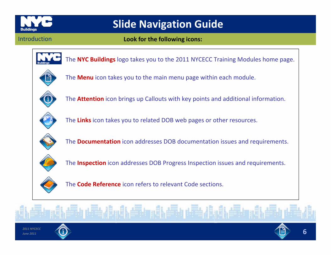
Slide Navigation GuideIntroduction Look for the following icons:
The NYC Buildings logo takes you to the 2011 NYCECC Training Modules home page.
TheMenu icon takes you to the main menu page within each module.The Menu icon takes you to the main menu page within each module.
The Attention icon brings up Callouts with key points and additional information.
The Links icon takes you to related DOB web pages or other resources.
The Documentation icon addresses DOB documentation issues and requirements.q
The Inspection icon addresses DOB Progress Inspection issues and requirements.
The Code Reference icon refers to relevant Code sections.
2011 NYCECC
June 2011 6
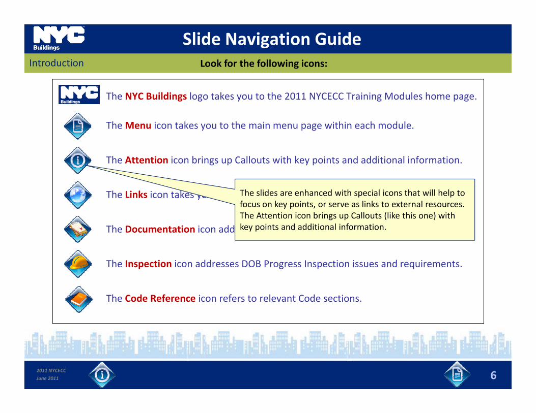
Slide Navigation GuideIntroduction Look for the following icons:
The NYC Buildings logo takes you to the 2011 NYCECC Training Modules home page.
TheMenu icon takes you to the main menu page within each module.The Menu icon takes you to the main menu page within each module.
The Attention icon brings up Callouts with key points and additional information.
The Links icon takes you to related DOB web pages or other resources.
The Documentation icon addresses DOB documentation issues and requirements.
The slides are enhanced with special icons that will help to focus on key points, or serve as links to external resources. The Attention icon brings up Callouts (like this one) with key points and additional information. q
The Inspection icon addresses DOB Progress Inspection issues and requirements.
The Code Reference icon refers to relevant Code sections.
2011 NYCECC
June 2011 6
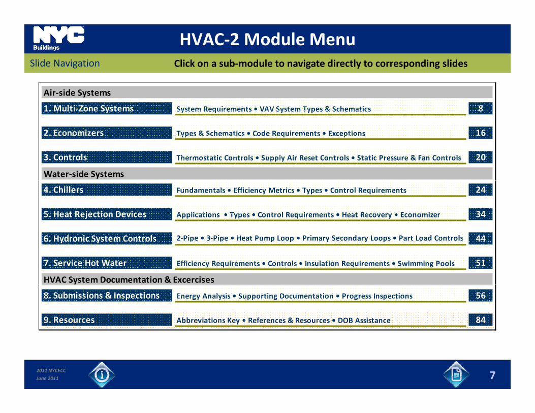
HVAC‐2 Module MenuClick on a sub‐module to navigate directly to corresponding slidesSlide Navigation
Air‐side Systems
1. Multi‐Zone Systems System Requirements • VAV System Types & Schematics 8
2. Economizers Types & Schematics • Code Requirements • Exceptions 16
3. Controls Thermostatic Controls • Supply Air Reset Controls • Static Pressure & Fan Controls 20
Water‐side Systems
4. Chillers Fundamentals • Efficiency Metrics • Types • Control Requirements 24
5. Heat Rejection Devices Applications • Types • Control Requirements • Heat Recovery • Economizer 34
6. Hydronic System Controls 2‐Pipe • 3‐Pipe • Heat Pump Loop • Primary Secondary Loops • Part Load Controls 44
7. Service Hot Water Efficiency Requirements • Controls • Insulation Requirements • Swimming Pools 51
HVAC System Documentation & Excercises
8. Submissions & Inspections Energy Analysis • Supporting Documentation • Progress Inspections 56
9. Resources Abbreviations Key • References & Resources • DOB Assistance 84
2011 NYCECC
June 2011 7
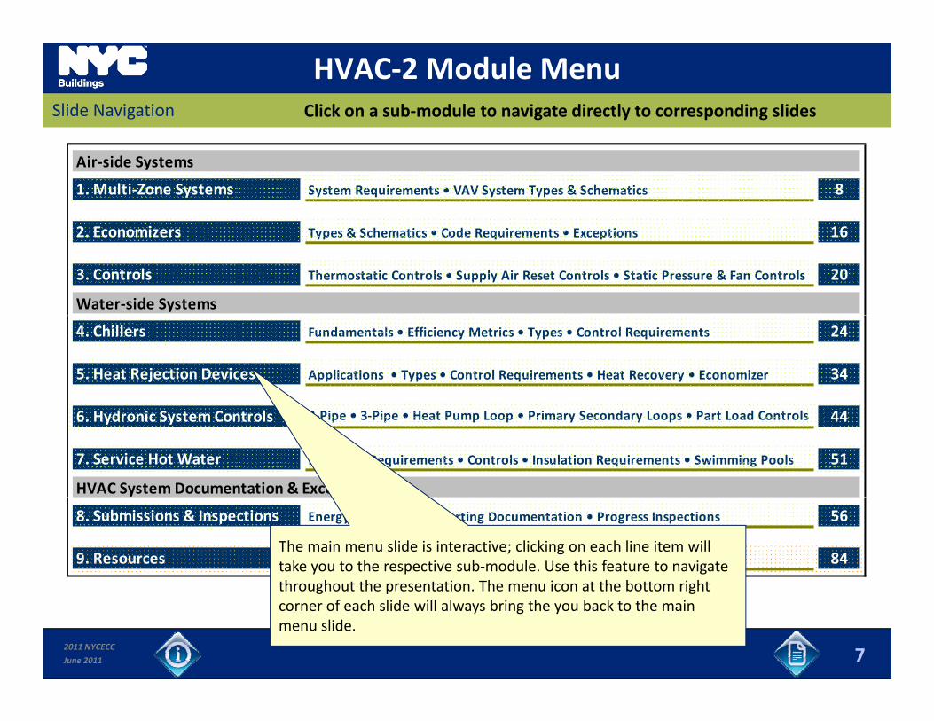
HVAC‐2 Module MenuClick on a sub‐module to navigate directly to corresponding slidesSlide Navigation
Air‐side Systems
1. Multi‐Zone Systems System Requirements • VAV System Types & Schematics 8
2. Economizers Types & Schematics • Code Requirements • Exceptions 16
3. Controls Thermostatic Controls • Supply Air Reset Controls • Static Pressure & Fan Controls 20
Water‐side Systems
4. Chillers Fundamentals • Efficiency Metrics • Types • Control Requirements 24
5. Heat Rejection Devices Applications • Types • Control Requirements • Heat Recovery • Economizer 34
6. Hydronic System Controls 2‐Pipe • 3‐Pipe • Heat Pump Loop • Primary Secondary Loops • Part Load Controls 44
7. Service Hot Water Efficiency Requirements • Controls • Insulation Requirements • Swimming Pools 51
HVAC System Documentation & Excercises
8. Submissions & Inspections Energy Analysis • Supporting Documentation • Progress Inspections 56
9. Resources Abbreviations Key • References & Resources • DOB Assistance 84The main menu slide is interactive; clicking on each line item will take you to the respective sub‐module. Use this feature to navigate throughout the presentation The menu icon at the bottom right
2011 NYCECC
June 2011 7
throughout the presentation. The menu icon at the bottom right corner of each slide will always bring the you back to the main menu slide.
1. Multiple Zone Air‐side SystemsSlides 8 to 15 Sub‐Module Overview
In this section you will learn about:
Code requirements for Complex air‐side HVAC systems;
Overview of Variable Air Volume (VAV) systems including general concepts, review of schematics for different configurations and key components; and y p ;
Understand differences and requirements for Single Duct VAV, Dual Duct VAV, Single Fan Dual Duct & Mixing VAV systems.
2011 NYCECC
June 2011 8
1. Multi‐Zone
Complex Air Side HVAC Systems? What are key Code requirements for HVAC systems serving multiple zones?
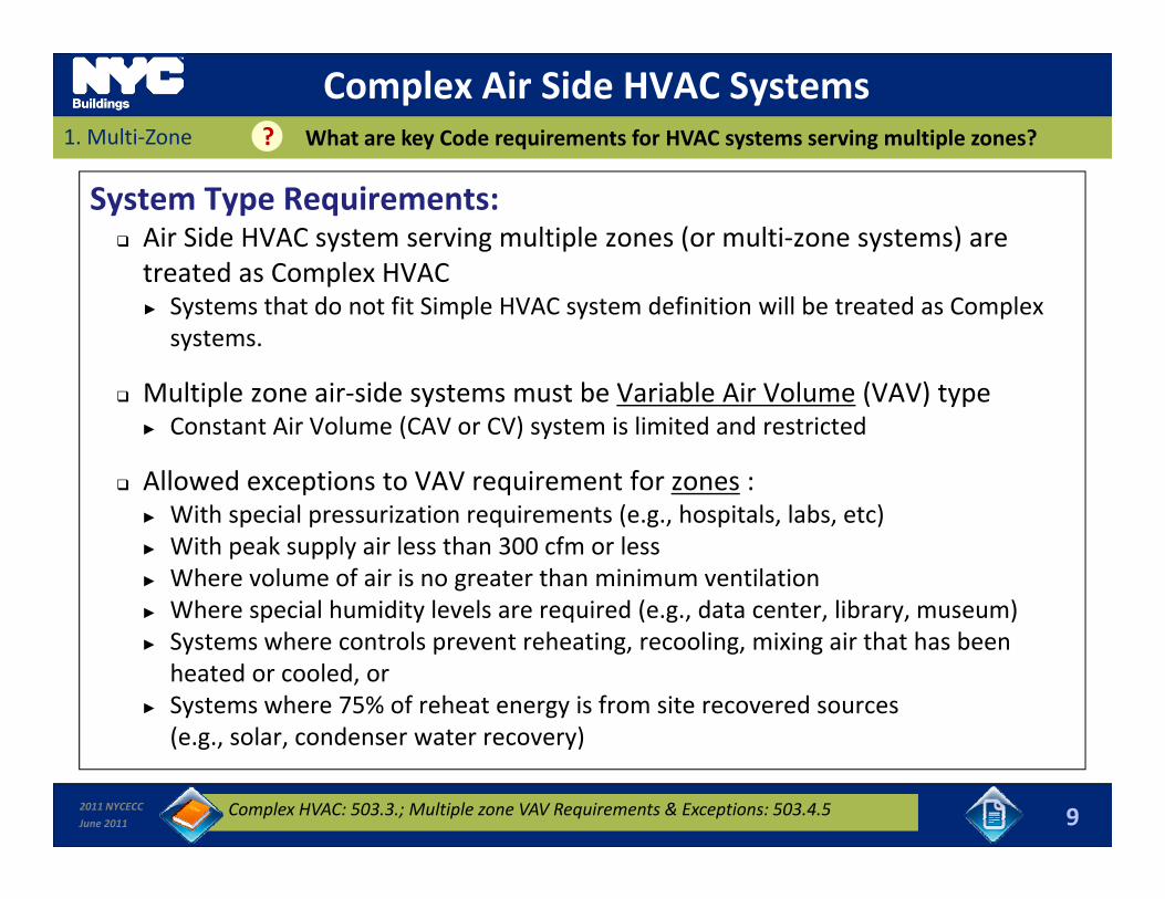
System Type Requirements: Air Side HVAC system serving multiple zones (or multi‐zone systems) are treated as Complex HVACtreated as Complex HVAC► Systems that do not fit Simple HVAC system definition will be treated as Complex
systems.
Multiple zone air side systems must be Variable Air Volume (VAV) type Multiple zone air‐side systems must be Variable Air Volume (VAV) type► Constant Air Volume (CAV or CV) system is limited and restricted
Allowed exceptions to VAV requirement for zones :Wi h i l i i i ( h i l l b )► With special pressurization requirements (e.g., hospitals, labs, etc)
► With peak supply air less than 300 cfm or less► Where volume of air is no greater than minimum ventilation► Where special humidity levels are required (e.g., data center, library, museum)p y q ( g , , y, )► Systems where controls prevent reheating, recooling, mixing air that has been
heated or cooled, or► Systems where 75% of reheat energy is from site recovered sources
(e g solar condenser water recovery)
2011 NYCECC
June 2011
(e.g., solar, condenser water recovery)
9Complex HVAC: 503.3.; Multiple zone VAV Requirements & Exceptions: 503.4.5
1. Multi Zone
Complex Air Side HVAC Systems? What are key Code requirements for HVAC systems serving multiple zones?
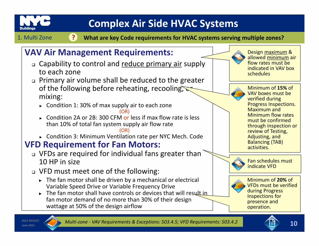
VAV Air Management Requirements: Capability to control and reduce primary air supply to each zone
Design maximum & allowed minimum air flow rates must be indicated in VAV box schedules
Primary air volume shall be reduced to the greater of the following before reheating, recooling, or mixing:► Condition 1: 30% of max supply air to each zone
Minimum of 15% of VAV boxes must be verified during Progress Inspections.
dpp y(OR)
► Condition 2A or 2B: 300 CFM or less if max flow rate is less than 10% of total fan system supply air flow rate
(OR)► Condition 3: Minimum Ventilation rate per NYC Mech. Code
Maximum and Minimum flow rates must be confirmed through inspection or review of Testing, Adjusting, and p
VFD Requirement for Fan Motors: VFDs are required for individual fans greater than 10 HP in size VFD t t f th f ll i
j g,Balancing (TAB) activities.
Fan schedules must indicate VFD
VFD must meet one of the following:► The fan motor shall be driven by a mechanical or electrical
Variable Speed Drive or Variable Frequency Drive► The fan motor shall have controls or devices that will result in
fan motor demand of no more than 30% of their design
Minimum of 20% of VFDs must be verified during Progress Inspections for presence and
2011 NYCECC
June 2011
fan motor demand of no more than 30% of their design wattage at 50% of the design airflow
10Multi‐zone ‐ VAV Requirements & Exceptions: 503.4.5; VFD Requirements: 503.4.2
presence and operation.
1. Multi Zone
Multi‐Zone Systems? How is minimum Primary Air Volume calculated for a VAV zone ?
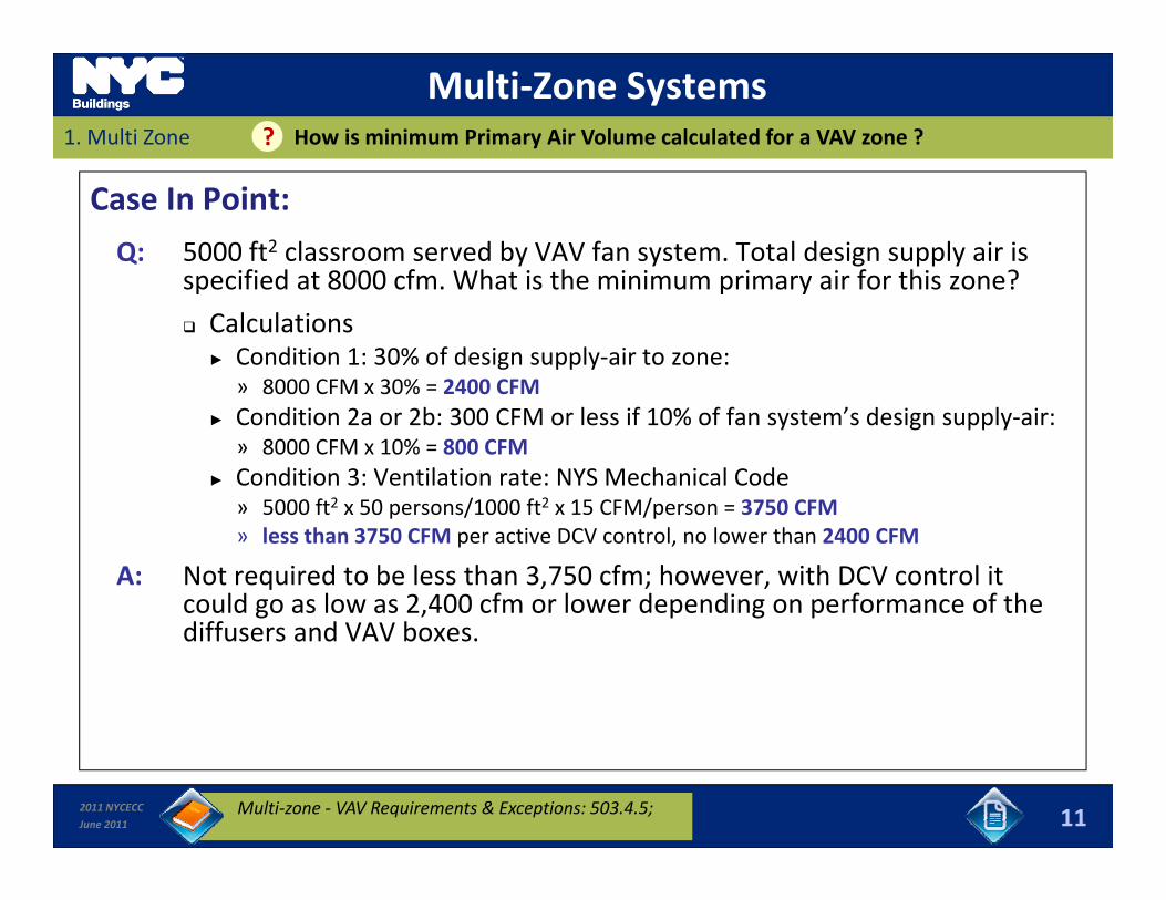
Case In Point:
Q: 5000 ft2 classroom served by VAV fan system. Total design supply air is specified at 8000 cfm What is the minimum primary air for this zone?specified at 8000 cfm. What is the minimum primary air for this zone?
Calculations► Condition 1: 30% of design supply‐air to zone:
» 8000 CFM x 30% = 2400 CFM8000 CFM x 30% 2400 CFM► Condition 2a or 2b: 300 CFM or less if 10% of fan system’s design supply‐air:
» 8000 CFM x 10% = 800 CFM► Condition 3: Ventilation rate: NYS Mechanical Code
» 5000 ft2 x 50 persons/1000 ft2 x 15 CFM/person = 3750 CFM» 5000 ft2 x 50 persons/1000 ft2 x 15 CFM/person = 3750 CFM» less than 3750 CFM per active DCV control, no lower than 2400 CFM
A: Not required to be less than 3,750 cfm; however, with DCV control it could go as low as 2,400 cfm or lower depending on performance of the diffusers and VAV boxes.
2011 NYCECC
June 2011 11Multi‐zone ‐ VAV Requirements & Exceptions: 503.4.5;
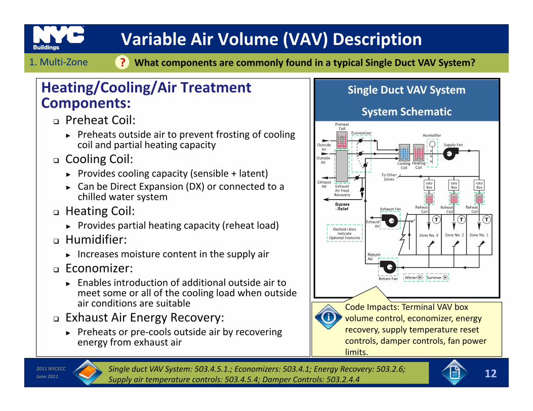
Variable Air Volume (VAV) Description1. Multi‐Zone What components are commonly found in a typical Single Duct VAV System??
Heating/Cooling/Air Treatment Components:
Preheat Coil:
Single Duct VAV System
System Schematic
► Preheats outside air to prevent frosting of cooling coil and partial heating capacity
Cooling Coil: ► Provides cooling capacity (sensible + latent)► Can be Direct Expansion (DX) or connected to a
chilled water system Heating Coil:
► Provides partial heating capacity (reheat load) Humidifier:
► Increases moisture content in the supply air Economizer:
► Enables introduction of additional outside air to► Enables introduction of additional outside air to meet some or all of the cooling load when outside air conditions are suitable
Exhaust Air Energy Recovery: ► Preheats or pre‐cools outside air by recovering
Code Impacts: Terminal VAV box volume control, economizer, energy recovery, supply temperature reset
2011 NYCECC
June 2011
► e eats o p e coo s outs de a by eco e genergy from exhaust air
12
controls, damper controls, fan power limits.
Single duct VAV System: 503.4.5.1.; Economizers: 503.4.1; Energy Recovery: 503.2.6; Supply air temperature controls: 503.4.5.4; Damper Controls: 503.2.4.4
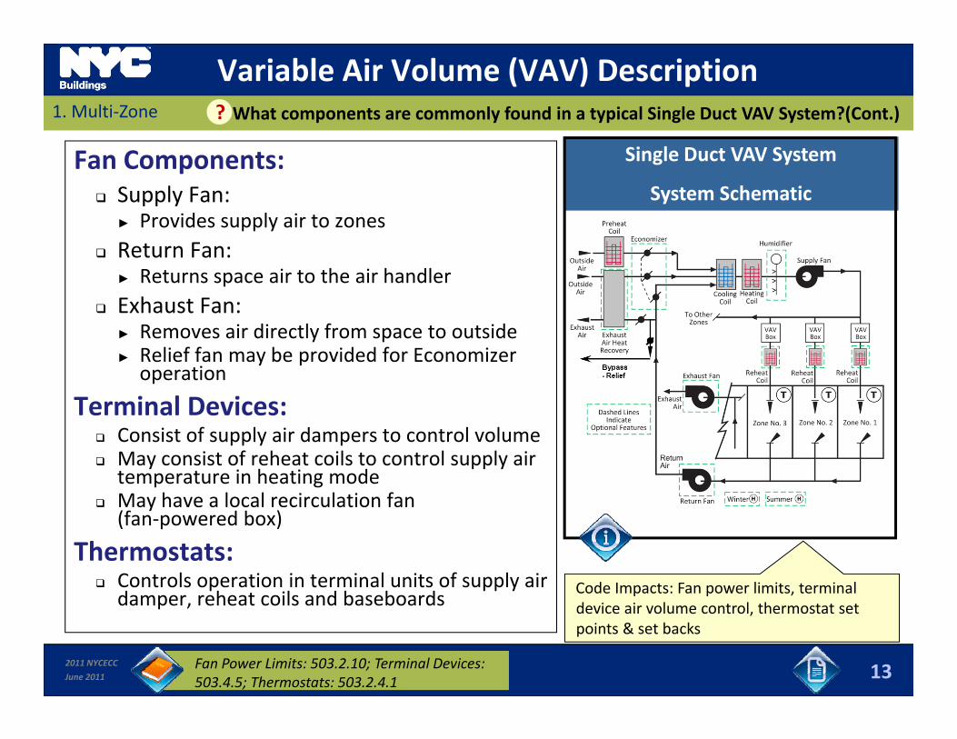
Variable Air Volume (VAV) Description1. Multi‐Zone What components are commonly found in a typical Single Duct VAV System?(Cont.)?
Fan Components: Supply Fan:
► Provides supply air to zones
Single Duct VAV System
System Schematicpp y
Return Fan: ► Returns space air to the air handler
Exhaust Fan:► Removes air directly from space to outside► Relief fan may be provided for Economizer operation
Terminal Devices: Consist of supply air dampers to control volume May consist of reheat coils to control supply air temperature in heating mode
May have a local recirculation fany(fan‐powered box)
Thermostats: Controls operation in terminal units of supply air damper reheat coils and baseboards Code Impacts: Fan power limits, terminal
d i i l l h
2011 NYCECC
June 2011
damper, reheat coils and baseboards
13
device air volume control, thermostat set points & set backs
Fan Power Limits: 503.2.10; Terminal Devices: 503.4.5; Thermostats: 503.2.4.1
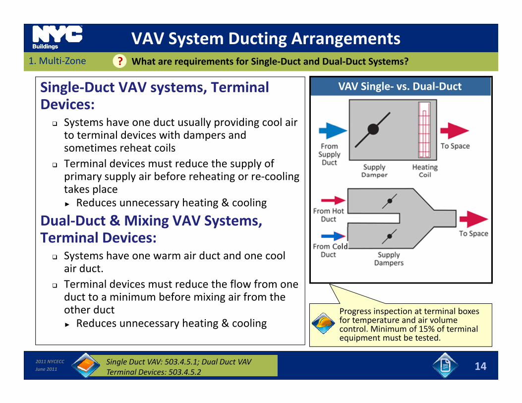
VAV System Ducting Arrangements1. Multi‐Zone What are requirements for Single‐Duct and Dual‐Duct Systems??
Single‐Duct VAV systems, Terminal Devices:
Systems have one duct usually providing cool air
VAV Single‐ vs. Dual‐Duct
Systems have one duct usually providing cool air to terminal devices with dampers and sometimes reheat coils
Terminal devices must reduce the supply of primary supply air before reheating or re coolingprimary supply air before reheating or re‐cooling takes place► Reduces unnecessary heating & cooling
Dual‐Duct & Mixing VAV Systems, g y ,Terminal Devices:
Systems have one warm air duct and one cool air duct.
Terminal devices must reduce the flow from one duct to a minimum before mixing air from the other duct► Reduces unnecessary heating & cooling
Progress inspection at terminal boxes for temperature and air volume control Minimum of 15% of terminal
2011 NYCECC
June 2011
y g g
14Single Duct VAV: 503.4.5.1; Dual Duct VAV Terminal Devices: 503.4.5.2
control. Minimum of 15% of terminal equipment must be tested.
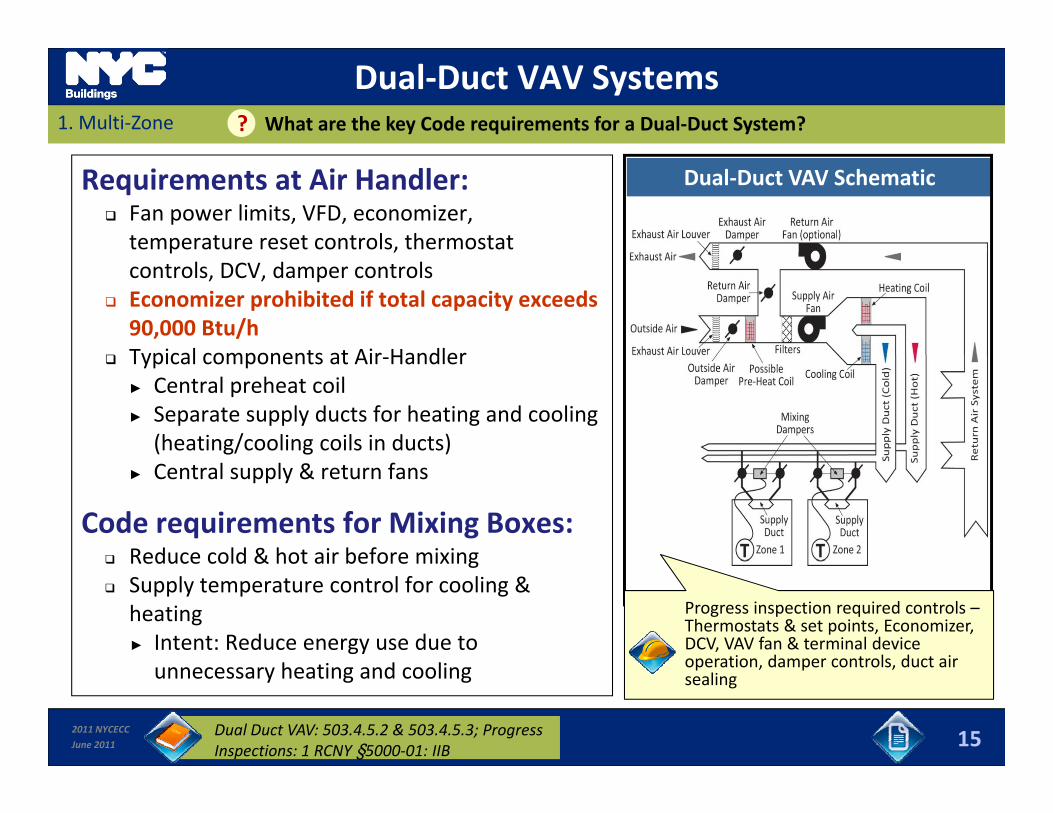
Dual‐Duct VAV Systems1. Multi‐Zone What are the key Code requirements for a Dual‐Duct System??
Requirements at Air Handler: Fan power limits, VFD, economizer, temperature reset controls, thermostat
Dual‐Duct VAV Schematic
pcontrols, DCV, damper controls
Economizer prohibited if total capacity exceeds 90,000 Btu/h
Typical components at Air Handler Typical components at Air‐Handler► Central preheat coil► Separate supply ducts for heating and cooling
(heating/cooling coils in ducts)► Central supply & return fans
Code requirements for Mixing Boxes: Reduce cold & hot air before mixing Reduce cold & hot air before mixing Supply temperature control for cooling &
heating► Intent: Reduce energy use due to
h i d li
Progress inspection required controls –Thermostats & set points, Economizer, DCV, VAV fan & terminal device operation damper controls duct air
2011 NYCECC
June 2011
unnecessary heating and cooling
15Dual Duct VAV: 503.4.5.2 & 503.4.5.3; Progress Inspections: 1 RCNY §5000‐01: IIB
operation, damper controls, duct air sealing

2. Air‐Side EconomizersSlides 16 to 19 Sub‐Module Overview
In this section you will learn about:
C d i t f f Ai Sid E i Code requirements for use of Air‐Side Economizers;
Types of Economizers and schematics; and
Allowable exceptions for Economizer requirements.
2011 NYCECC
June 2011 16
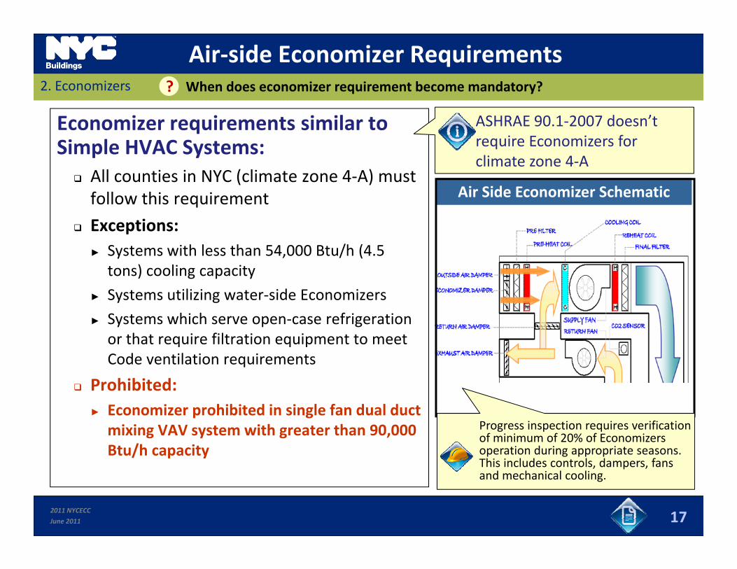
Air‐side Economizer Requirements2. Economizers When does economizer requirement become mandatory??
Economizer requirements similar to Simple HVAC Systems:
All counties in NYC (climate zone 4‐A) must
ASHRAE 90.1‐2007 doesn’t require Economizers for climate zone 4‐A
All counties in NYC (climate zone 4‐A) must follow this requirement
Exceptions:Systems with less than 54 000 Btu/h (4 5
Air Side Economizer Schematic
► Systems with less than 54,000 Btu/h (4.5 tons) cooling capacity
► Systems utilizing water‐side Economizers
► Systems which serve open‐case refrigeration► Systems which serve open case refrigeration or that require filtration equipment to meet Code ventilation requirements
Prohibited:► Economizer prohibited in single fan dual duct mixing VAV system with greater than 90,000 Btu/h capacity
Progress inspection requires verification of minimum of 20% of Economizers operation during appropriate seasons. This includes controls dampers fans
2011 NYCECC
June 2011 17
This includes controls, dampers, fans and mechanical cooling.

Psychrometric Properties of Air2. Economizers What properties of air are important for influencing economizer operation??
Temperature: Increasing temperature means higher (sensible) energy in the air, and also raises the amount of water the air is capable of containingamount of water the air is capable of containing
Humidity: Humidity is a measure of the moisture content of air
Increasing humidity means higher (latent) energy in the air which puts a higher load Increasing humidity means higher (latent) energy in the air, which puts a higher load on a cooling system for dehumidification purposes
Can be determined by the wet‐bulb temperature of the ambient air
Enthalpy:Enthalpy: Measures total energy (sensible + latent) in the air (units are Btu/Lb)
Warmer, more moist air will always contain more energy than colder, drier airdrier air
Cold, moist air can contain more energy than hot, dry air!
2011 NYCECC
June 2011 18
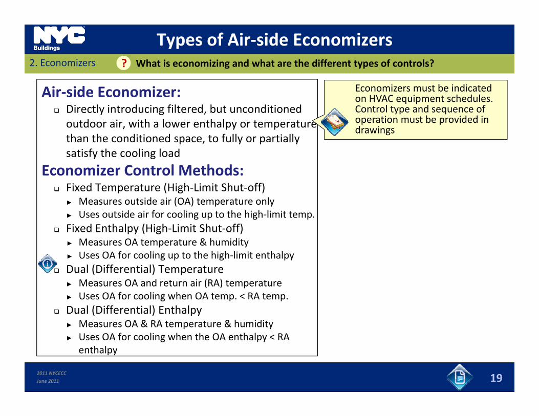
Types of Air‐side Economizers2. Economizers What is economizing and what are the different types of controls??
Air‐side Economizer: Directly introducing filtered, but unconditioned outdoor air, with a lower enthalpy or temperature
Economizers must be indicated on HVAC equipment schedules. Control type and sequence of operation must be provided in drawingspy p
than the conditioned space, to fully or partially satisfy the cooling load
Economizer Control Methods:
drawings
Fixed Temperature (High‐Limit Shut‐off)► Measures outside air (OA) temperature only► Uses outside air for cooling up to the high‐limit temp.
Fixed Enthalpy (High‐Limit Shut‐off)► Measures OA temperature & humidity► Uses OA for cooling up to the high‐limit enthalpy
Dual (Differential) Temperature► Measures OA and return air (RA) temperature( ) p► Uses OA for cooling when OA temp. < RA temp.
Dual (Differential) Enthalpy► Measures OA & RA temperature & humidity► Uses OA for cooling when the OA enthalpy < RA
2011 NYCECC
June 2011
► Uses OA for cooling when the OA enthalpy < RA enthalpy
19
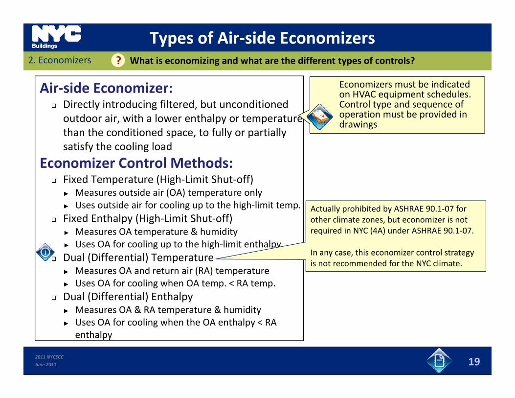
Types of Air‐side Economizers2. Economizers What is economizing and what are the different types of controls??
Air‐side Economizer: Directly introducing filtered, but unconditioned outdoor air, with a lower enthalpy or temperature
Economizers must be indicated on HVAC equipment schedules. Control type and sequence of operation must be provided in drawingspy p
than the conditioned space, to fully or partially satisfy the cooling load
Economizer Control Methods:
drawings
Fixed Temperature (High‐Limit Shut‐off)► Measures outside air (OA) temperature only► Uses outside air for cooling up to the high‐limit temp.
Fixed Enthalpy (High‐Limit Shut‐off)Actually prohibited by ASHRAE 90.1‐07 for other climate zones, but economizer is not
► Measures OA temperature & humidity► Uses OA for cooling up to the high‐limit enthalpy
Dual (Differential) Temperature► Measures OA and return air (RA) temperature
required in NYC (4A) under ASHRAE 90.1‐07.
In any case, this economizer control strategy is not recommended for the NYC climate.
( ) p► Uses OA for cooling when OA temp. < RA temp.
Dual (Differential) Enthalpy► Measures OA & RA temperature & humidity► Uses OA for cooling when the OA enthalpy < RA
2011 NYCECC
June 2011
► Uses OA for cooling when the OA enthalpy < RA enthalpy
19
3. Controls (Air‐Side, Complex Systems)Slides 20 to 23 Sub‐Module Overview
In this section you will learn about:
Th t ti t l i t Thermostatic control requirements;
Supply air reset controls requirements; and
Static pressure and fan control requirements.
2011 NYCECC
June 2011 20
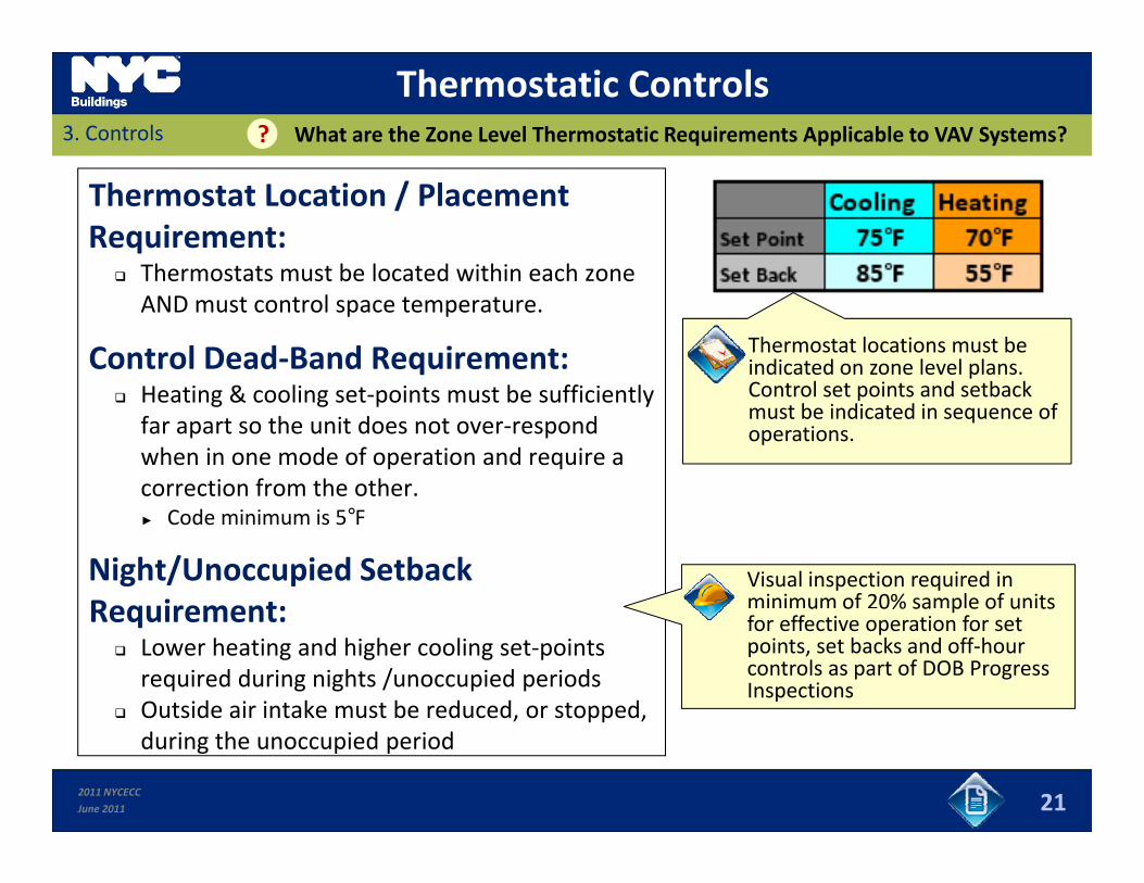
Thermostatic Controls3. Controls What are the Zone Level Thermostatic Requirements Applicable to VAV Systems??
Thermostat Location / Placement Requirement:
Thermostats must be located within each zone Thermostats must be located within each zone AND must control space temperature.
Control Dead‐Band Requirement:H i & li i b ffi i l
Thermostat locations must be indicated on zone level plans. Control set points and setback Heating & cooling set‐points must be sufficiently
far apart so the unit does not over‐respond when in one mode of operation and require a correction from the other.
Control set points and setback must be indicated in sequence of operations.
► Code minimum is 5°F
Night/Unoccupied Setback Requirement:
Visual inspection required in minimum of 20% sample of units Requirement:
Lower heating and higher cooling set‐points required during nights /unoccupied periods
Outside air intake must be reduced, or stopped,
u o 0% sa p e o u tsfor effective operation for set points, set backs and off‐hour controls as part of DOB Progress Inspections
2011 NYCECC
June 2011
, pp ,during the unoccupied period
21
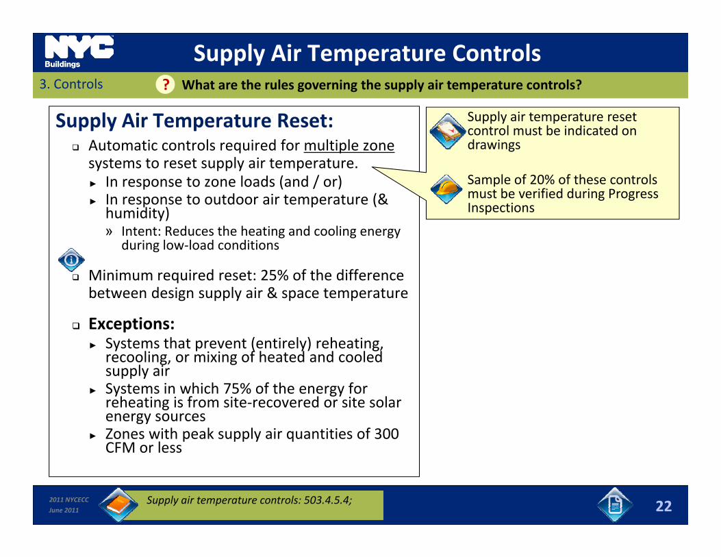
Supply Air Temperature Controls3. Controls What are the rules governing the supply air temperature controls??
Supply Air Temperature Reset: Automatic controls required for multiple zone systems to reset supply air temperature.
Supply air temperature reset control must be indicated on drawings
► In response to zone loads (and / or)► In response to outdoor air temperature (& humidity)» Intent: Reduces the heating and cooling energy
during low load conditions
Sample of 20% of these controls must be verified during Progress Inspections
during low‐load conditions
Minimum required reset: 25% of the difference between design supply air & space temperature
Exceptions:► Systems that prevent (entirely) reheating, recooling, or mixing of heated and cooled supply airS t i hi h 75% f th f► Systems in which 75% of the energy for reheating is from site‐recovered or site solar energy sources
► Zones with peak supply air quantities of 300 CFM or less
2011 NYCECC
June 2011 22Supply air temperature controls: 503.4.5.4;
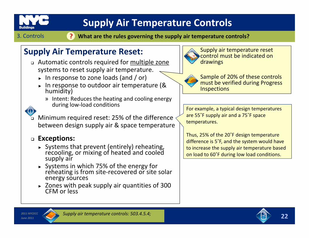
Supply Air Temperature Controls3. Controls What are the rules governing the supply air temperature controls??
Supply Air Temperature Reset: Automatic controls required for multiple zone systems to reset supply air temperature.
Supply air temperature reset control must be indicated on drawings
► In response to zone loads (and / or)► In response to outdoor air temperature (& humidity)» Intent: Reduces the heating and cooling energy
during low load conditions
Sample of 20% of these controls must be verified during Progress Inspections
during low‐load conditions
Minimum required reset: 25% of the difference between design supply air & space temperature
For example, a typical design temperatures are 55˚F supply air and a 75˚F space temperatures.
Thus 25% of the 20˚F design temperature Exceptions:
► Systems that prevent (entirely) reheating, recooling, or mixing of heated and cooled supply airS t i hi h 75% f th f
Thus, 25% of the 20 F design temperature difference is 5˚F, and the system would have to increase the supply air temperature based on load to 60˚F during low load conditions.
► Systems in which 75% of the energy for reheating is from site‐recovered or site solar energy sources
► Zones with peak supply air quantities of 300 CFM or less
2011 NYCECC
June 2011 22Supply air temperature controls: 503.4.5.4;

Static Pressure & Fan Controls3. Controls What are the Details of Static Pressure and Fan Controls??
Static Pressure (SP) Reset: SP based reset control required where there is DDC control at VAV boxes
DDC & SP Reset control must be indicated on drawings
Sample of 20% of SP Reset there is DDC control at VAV boxes► Intent: Reduces fan energy consumption
when loads are satisfied in most zones.
pcontrols must be verified during Progress Inspections
Fan Controls: Electrical or mechanical variable speed d i i d f f t tdrives are required for fan motors greater than 10 HP. ► Or fan control device results in 30% design power at 50% design flow when SP set‐pointpower at 50% design flow when SP set‐point is 33% of total design static pressure.
2011 NYCECC
June 2011 23Fan VFD & Static Pressure controls: 503.4.2
4. ChillersSlides 24 to 33 Sub‐Module Overview
In this section you will learn about:
What a Chiller is – as well as different Chiller technologies such as gVapor‐Compression Chillers and Absorption Chillers;
Condenser types; and Condenser types; and
Rating conditions / controls.
2011 NYCECC
June 2011 24
Chillers4. Chillers What is a Chiller??
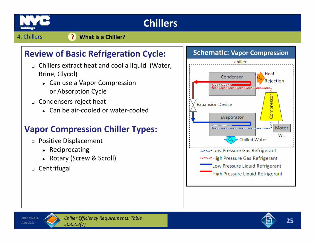
Review of Basic Refrigeration Cycle: Chillers extract heat and cool a liquid (Water, Brine, Glycol)
Schematic: Vapor Compression
Brine, Glycol)► Can use a Vapor Compression or Absorption Cycle
Condensers reject heat► Can be air‐cooled or water‐cooled
Vapor Compression Chiller Types: Positive Displacement
► Reciprocating ► Rotary (Screw & Scroll)Centrifugal Centrifugal
2011 NYCECC
June 2011 25Chiller Efficiency Requirements: Table 503.2.3(7)
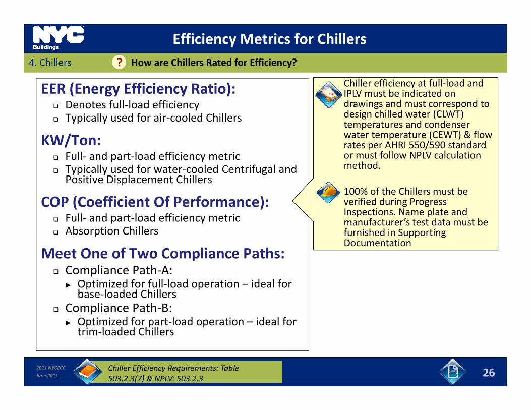
Efficiency Metrics for Chillers4. Chillers How are Chillers Rated for Efficiency??
EER (Energy Efficiency Ratio): Denotes full‐load efficiency Typically used for air‐cooled Chillers
Chiller efficiency at full‐load and IPLV must be indicated on drawings and must correspond to design chilled water (CLWT) temperatures and condenser
KW/Ton: Full‐ and part‐load efficiency metric Typically used for water‐cooled Centrifugal and Positive Displacement Chillers
temperatures and condenser water temperature (CEWT) & flow rates per AHRI 550/590 standard or must follow NPLV calculation method.
Positive Displacement Chillers
COP (Coefficient Of Performance): Full‐ and part‐load efficiency metric Absorption Chillers
100% of the Chillers must be verified during Progress Inspections. Name plate and manufacturer’s test data must be furnished in Supporting Absorption Chillers
Meet One of Two Compliance Paths: Compliance Path‐A:
Optimized for full load operation ideal for
furnished in Supporting Documentation
► Optimized for full‐load operation – ideal for base‐loaded Chillers
Compliance Path‐B:► Optimized for part‐load operation – ideal for
trim‐loaded Chillers
Version 2 262011 NYCECC
June 2011
trim loaded Chillers
26Chiller Efficiency Requirements: Table 503.2.3(7) & NPLV: 503.2.3
4. Chillers
Rating ConditionsHow are chillers rated for efficiency??
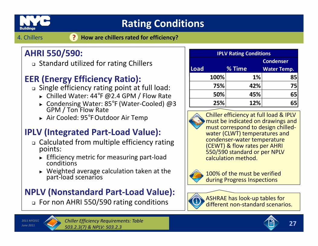
AHRI 550/590: Standard utilized for rating Chillers
EER (E Effi i R ti )EER (Energy Efficiency Ratio): Single efficiency rating point at full load:
► Chilled Water: 44°[email protected] GPM / Flow Rate► Condensing Water: 85°F (Water‐Cooled) @3
GPM / T Fl RGPM / Ton Flow Rate► Air Cooled: 95°F Outdoor Air Temp
IPLV (Integrated Part‐Load Value):
Chiller efficiency at full load & IPLV must be indicated on drawings and must correspond to design chilled‐water (CLWT) temperatures and condenser water temperature
Calculated from multiple efficiency rating points:► Efficiency metric for measuring part‐load
conditionsW i ht d l l ti t k t th
condenser‐water temperature (CEWT) & flow rates per AHRI 550/590 standard or per NPLV calculation method.
► Weighted average calculation taken at the part‐load scenarios
NPLV (Nonstandard Part‐Load Value):F AHRI 550/590 ti diti
100% of the must be verified during Progress Inspections
ASHRAE has look‐up tables for
2011 NYCECC
June 2011
For non AHRI 550/590 rating conditions
27Chiller Efficiency Requirements: Table 503.2.3(7) & NPLV: 503.2.3
pdifferent non‐standard scenarios.
Chiller Efficiency Requirements4. Chillers How are Chillers Rated for Efficiency??
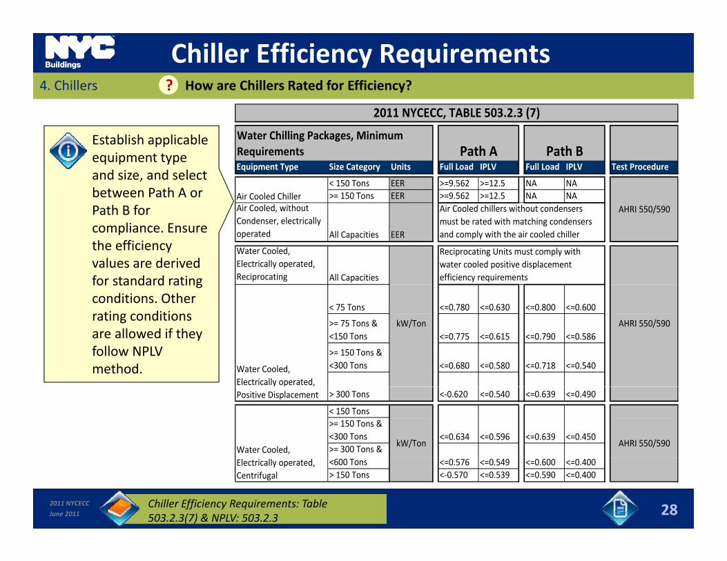
Equipment Type Size Category Units Full Load IPLV Full Load IPLV Test ProcedurePath A Path B
Water Chilling Packages, Minimum Requirements
2011 NYCECC, TABLE 503.2.3 (7)
Establish applicable equipment type and size and select
< 150 Tons EER >=9.562 >=12.5 NA NA>= 150 Tons EER >=9.562 >=12.5 NA NA
Air Cooled, without Condenser, electrically operated All Capacities EER
Air Cooled ChillerAir Cooled chillers without condensers must be rated with matching condensers and comply with the air cooled chiller
AHRI 550/590
and size, and select between Path A or Path B for compliance. Ensure the efficiency Water Cooled,
Electrically operated, Reciprocating All Capacities
< 75 Tons <=0.780 <=0.630 <=0.800 <=0.600
Reciprocating Units must comply with water cooled positive displacement efficiency requirements
the efficiency values are derived for standard rating conditions. Other rating conditions
>= 75 Tons &<150 Tons <=0.775 <=0.615 <=0.790 <=0.586
>= 150 Tons &<300 Tons <=0.680 <=0.580 <=0.718 <=0.540
AHRI 550/590
Water Cooled, Electrically operated,
kW/Tonrating conditions are allowed if they follow NPLV method.
> 300 Tons <‐0.620 <=0.540 <=0.639 <=0.490
< 150 Tons>= 150 Tons &<300 Tons>= 300 Tons &
<=0.634 <=0.596 <=0.639 <=0.450Water Cooled,
kW/Ton AHRI 550/590
Positive Displacement
2011 NYCECC
June 2011
<600 Tons <=0.576 <=0.549 <=0.600 <=0.400> 150 Tons <‐0.570 <=0.539 <=0.590 <=0.400
Electrically operated, Centrifugal
Chiller Efficiency Requirements: Table 503.2.3(7) & NPLV: 503.2.3 28

Efficiency Metrics4. Chillers ? Which Chiller Efficiency Metrics Apply for Non‐Standard Operating Conditions?
NPLV (Non‐standard Part‐Load Value): Single number part‐load efficiency metric analogous to IPLV
Non Standard Adjustment FactorFull Load and IPLV valuesfrom Table 503.2.3(7)
Adj t d V l T bl l / K Different rating conditions (non‐standard) than for IPLV
Applicable for non‐standard operating conditions within limits:
Adjusted Values = Table values / Kadj
Kadj = 6.174722 ‐ 0.303668(X) +0.00629466 (X)2 ‐ 0.000045780 (X)3
X = DT + LIFTconditions within limits:► Minimum leaving chilled water 38°F► Maximum condensing entering water temperature:
102°F► Condensing water flow rate: 1 to 6 gpm/ton
X = DTstd + LIFT
DTstd = { 24 + [Full load kW/ton from table 503.2.3(7)] x 6.83} / Flow
Flow = Condenser Water Flow (GPM) Cooling ► Condensing water flow rate: 1 to 6 gpm/ton
Calculation formula: Refer to Code
Code Exempt Chiller Applications:
Full Load Capacity (tons)
Lift = CEWT – CLWT (°F)
CEWT = Full Load Condenser Entering Water Temperature (°F)
Chillers operating outside these ranges Applications utilizing fluids or solutions with secondary coolants with freeze point less than 27°F (e.g., brine, water/glycol)
Temperature ( F)
CLWT = Full Load Leaving Chilled Water Temperature (°F)
Supporting Documents must
2011 NYCECC
June 2011
( g , , /g y )
29Chiller Efficiency Requirements: Table 503.2.3(7) & NPLV: 503.2.3
Supporting Documents must include all values needed for Kadj
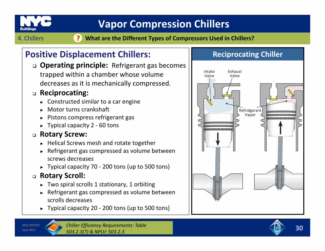
Vapor Compression Chillers4. Chillers What are the Different Types of Compressors Used in Chillers??
Positive Displacement Chillers: Operating principle: Refrigerant gas becomes trapped within a chamber whose volume
Reciprocating Chiller
decreases as it is mechanically compressed. Reciprocating:
► Constructed similar to a car engine► Motor turns crankshaft► Motor turns crankshaft► Pistons compress refrigerant gas► Typical capacity 2 ‐ 60 tons
Rotary Screw:H li l S h d t t t th► Helical Screws mesh and rotate together
► Refrigerant gas compressed as volume between screws decreases
► Typical capacity 70 ‐ 200 tons (up to 500 tons)R S ll Rotary Scroll:► Two spiral scrolls 1 stationary, 1 orbiting► Refrigerant gas compressed as volume between
scrolls decreases
2011 NYCECC
June 2011
► Typical capacity 20 ‐ 200 tons (up to 500 tons)
30Chiller Efficiency Requirements: Table 503.2.3(7) & NPLV: 503.2.3
Vapor Compression Chillers4. Chillers What are the different types of compressors used in Chillers??
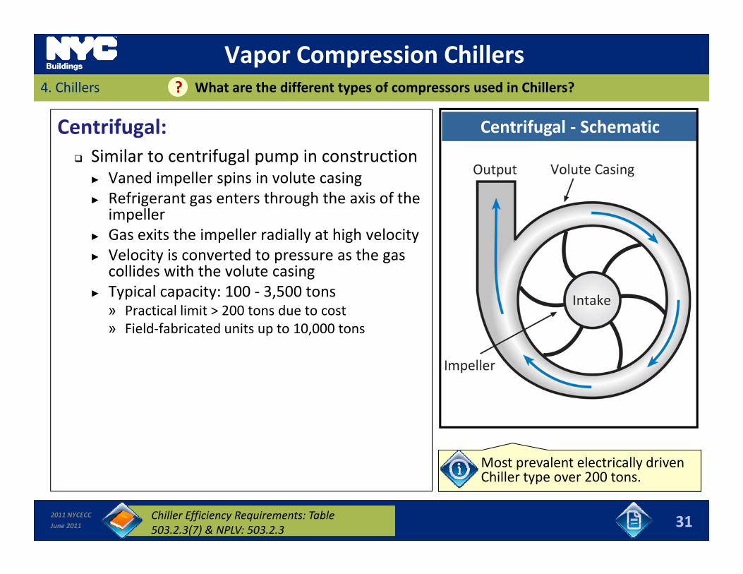
Centrifugal: Similar to centrifugal pump in construction
► Vaned impeller spins in volute casing
Centrifugal ‐ Schematic
► Vaned impeller spins in volute casing► Refrigerant gas enters through the axis of the
impeller► Gas exits the impeller radially at high velocity
V l it i t d t th► Velocity is converted to pressure as the gas collides with the volute casing
► Typical capacity: 100 ‐ 3,500 tons» Practical limit > 200 tons due to cost
ld f b d» Field‐fabricated units up to 10,000 tons
Most prevalent electrically driven
2011 NYCECC
June 2011 31
p yChiller type over 200 tons.
Chiller Efficiency Requirements: Table 503.2.3(7) & NPLV: 503.2.3
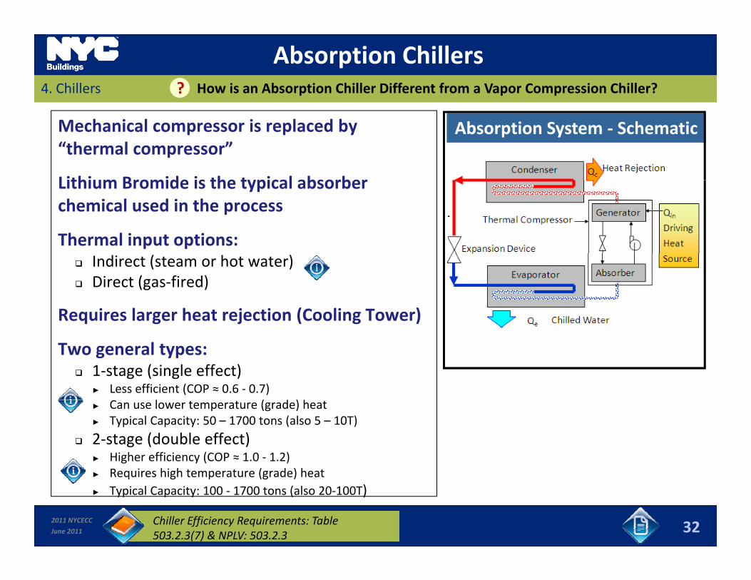
Absorption Chillers4. Chillers How is an Absorption Chiller Different from a Vapor Compression Chiller??
Mechanical compressor is replaced by “thermal compressor”
Lithium Bromide is the typical absorber
Absorption System ‐ Schematic
Lithium Bromide is the typical absorber chemical used in the process
Thermal input options: Indirect (steam or hot water) Direct (gas‐fired)
Requires larger heat rejection (Cooling Tower)
Two general types: 1‐stage (single effect)
► Less efficient (COP ≈ 0.6 ‐ 0.7)l ( d ) h► Can use lower temperature (grade) heat
► Typical Capacity: 50 – 1700 tons (also 5 – 10T)
2‐stage (double effect)► Higher efficiency (COP ≈ 1.0 ‐ 1.2)► Requires high temperature (grade) heat
2011 NYCECC
June 2011
► Requires high temperature (grade) heat► Typical Capacity: 100 ‐ 1700 tons (also 20‐100T)
32Chiller Efficiency Requirements: Table 503.2.3(7) & NPLV: 503.2.3
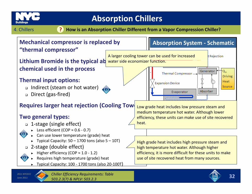
Absorption Chillers4. Chillers How is an Absorption Chiller Different from a Vapor Compression Chiller??
Mechanical compressor is replaced by “thermal compressor”
Lithium Bromide is the typical absorber
Absorption System ‐ Schematic
A larger cooling tower can be used for increased t id i f tiLithium Bromide is the typical absorber
chemical used in the process
Thermal input options:
water side economizer function.
Indirect (steam or hot water) Direct (gas‐fired)
Requires larger heat rejection (Cooling Tower)Low grade heat includes low pressure steam and
Two general types: 1‐stage (single effect)
► Less efficient (COP ≈ 0.6 ‐ 0.7)l ( d ) h
medium temperature hot water. Although lower efficiency, these units can make use of site recovered heat.
► Can use lower temperature (grade) heat► Typical Capacity: 50 – 1700 tons (also 5 – 10T)
2‐stage (double effect)► Higher efficiency (COP ≈ 1.0 ‐ 1.2)► Requires high temperature (grade) heat
High grade heat includes high pressure steam and high temperature hot water. Although higher efficiency, it is more difficult for these units to make use of site recovered heat from many sources
2011 NYCECC
June 2011
► Requires high temperature (grade) heat► Typical Capacity: 100 ‐ 1700 tons (also 20‐100T)
32Chiller Efficiency Requirements: Table 503.2.3(7) & NPLV: 503.2.3
use of site recovered heat from many sources.
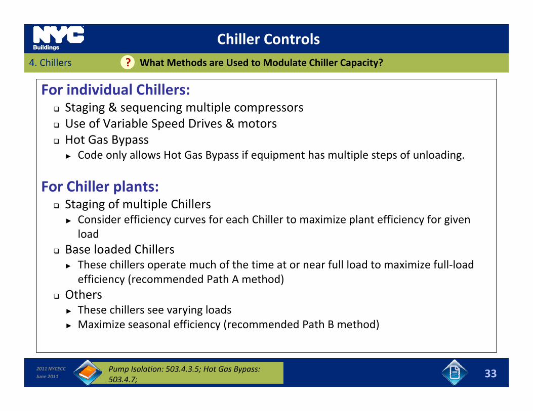
Chiller Controls4. Chillers What Methods are Used to Modulate Chiller Capacity??
For individual Chillers: Staging & sequencing multiple compressors Use of Variable Speed Drives & motorsp Hot Gas Bypass
► Code only allows Hot Gas Bypass if equipment has multiple steps of unloading.
For Chiller plants: Staging of multiple Chillers
► Consider efficiency curves for each Chiller to maximize plant efficiency for given l dload
Base loaded Chillers► These chillers operate much of the time at or near full load to maximize full‐load
efficiency (recommended Path A method)y ( ) Others
► These chillers see varying loads► Maximize seasonal efficiency (recommended Path B method)
2011 NYCECC
June 2011 33Pump Isolation: 503.4.3.5; Hot Gas Bypass: 503.4.7;
5. Heat Rejection EquipmentSlides 34 to 43 Learning Objectives
In this section you will learn about:
Applications That Need Heat Rejection Devices;
Types of Heat Rejection Devices;Dry Cooler► Dry Cooler
► Open Cooling Tower► Closed‐Circuit Evaporative Cooler
Control Requirements; and Control Requirements; and► Fan Speed► Applications in Heat Pump Loop
Condenser Heat Recovery & Water‐side Economizer.y
2011 NYCECC
June 2011 34
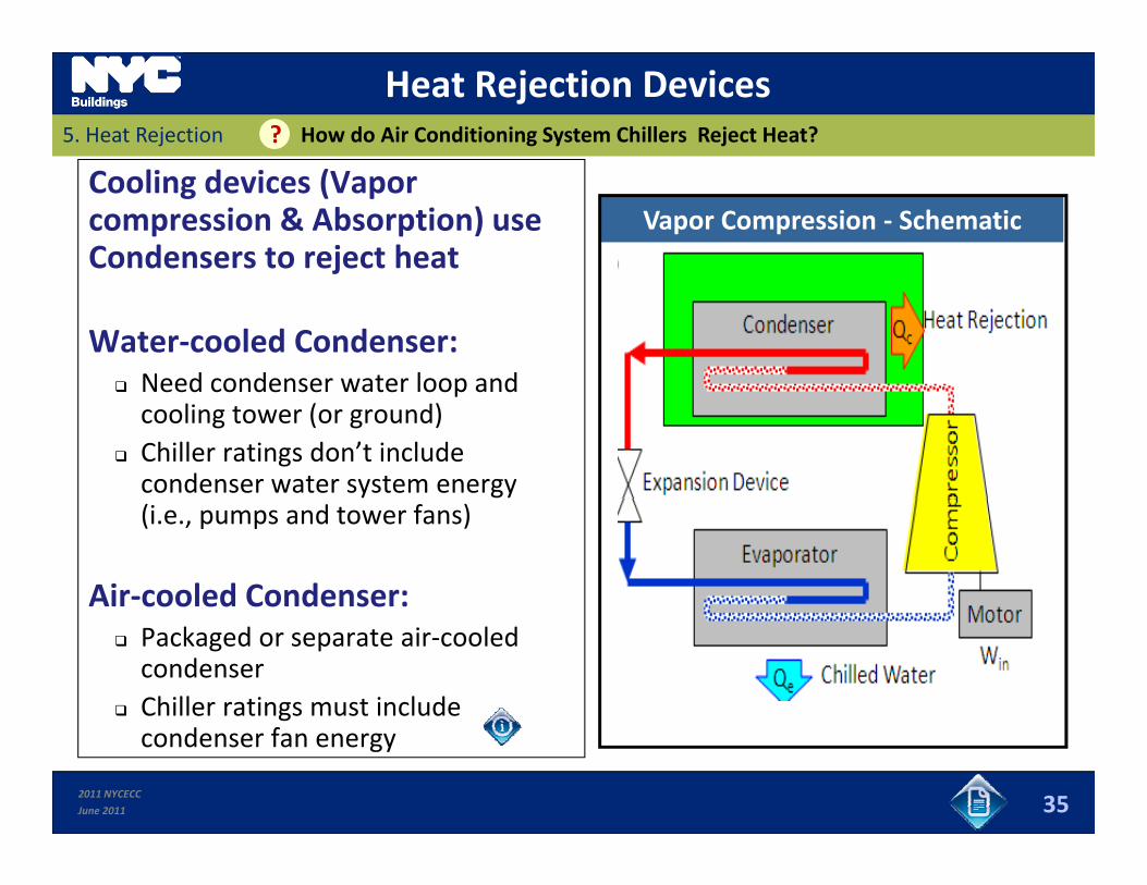
Heat Rejection DevicesHow do Air Conditioning System Chillers Reject Heat??5. Heat Rejection
Cooling devices (Vapor compression & Absorption) use Condensers to reject heat
Vapor Compression ‐ Schematic
Water‐cooled Condenser: Need condenser water loop and Need condenser water loop and cooling tower (or ground)
Chiller ratings don’t include condenser water system energy (i.e., pumps and tower fans)
Air‐cooled Condenser: Packaged or separate air‐cooled condenser
Chiller ratings must include
2011 NYCECC
June 2011
condenser fan energy
35
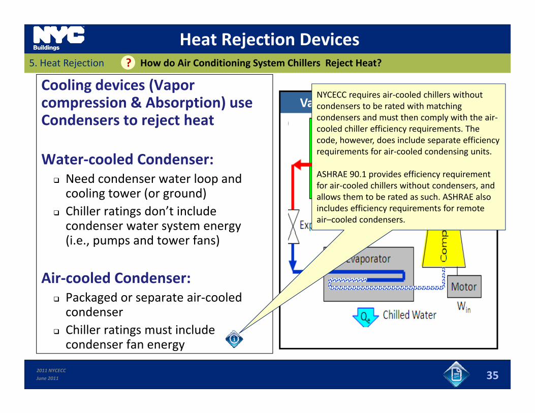
Heat Rejection DevicesHow do Air Conditioning System Chillers Reject Heat??5. Heat Rejection
Cooling devices (Vapor compression & Absorption) use Condensers to reject heat
Vapor Compression ‐ SchematicNYCECC requires air‐cooled chillers without condensers to be rated with matching condensers and must then comply with the air‐cooled chiller efficiency requirements The
Water‐cooled Condenser: Need condenser water loop and
cooled chiller efficiency requirements. The code, however, does include separate efficiency requirements for air‐cooled condensing units.
ASHRAE 90.1 provides efficiency requirement Need condenser water loop and cooling tower (or ground)
Chiller ratings don’t include condenser water system energy
for air‐cooled chillers without condensers, and allows them to be rated as such. ASHRAE also includes efficiency requirements for remote air–cooled condensers.
(i.e., pumps and tower fans)
Air‐cooled Condenser: Packaged or separate air‐cooled condenser
Chiller ratings must include
2011 NYCECC
June 2011
condenser fan energy
35
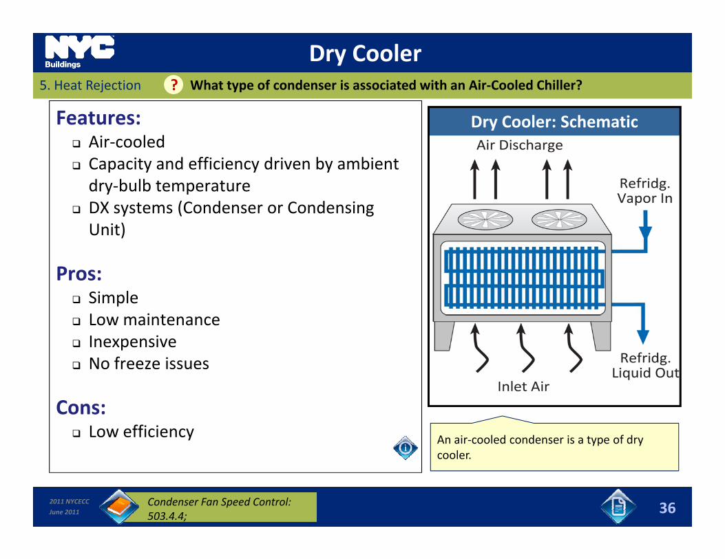
Dry Cooler5. Heat Rejection What type of condenser is associated with an Air‐Cooled Chiller??
Features: Air‐cooled Capacity and efficiency driven by ambient
Dry Cooler: Schematic
dry‐bulb temperature DX systems (Condenser or Condensing Unit)
Pros: SimpleL i t Low maintenance
Inexpensive No freeze issues
Cons: Low efficiency An air‐cooled condenser is a type of dry
cooler
2011 NYCECC
June 2011 36Condenser Fan Speed Control: 503.4.4;
cooler.
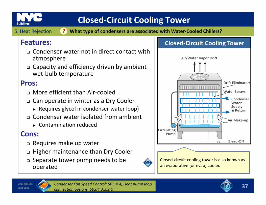
Closed‐Circuit Cooling Tower5. Heat Rejection What type of condensers are associated with Water‐Cooled Chillers??
Features: Condenser water not in direct contact with atmosphere
Closed‐Circuit Cooling Tower
Capacity and efficiency driven by ambient wet‐bulb temperature
Pros: More efficient than Air‐cooled Can operate in winter as a Dry Cooler
► Requires glycol in condenser water loop)C d t i l t d f bi t Condenser water isolated from ambient► Contamination reduced
Cons:R i k t Requires make up water
Higher maintenance than Dry Cooler Separate tower pump needs to be operated
Closed‐circuit cooling tower is also known as an evaporative (or evap) cooler.
2011 NYCECC
June 2011
operated
37Condenser Fan Speed Control: 503.4.4; Heat pump loop connection options: 503.4.3.3.2.1
p ( p)
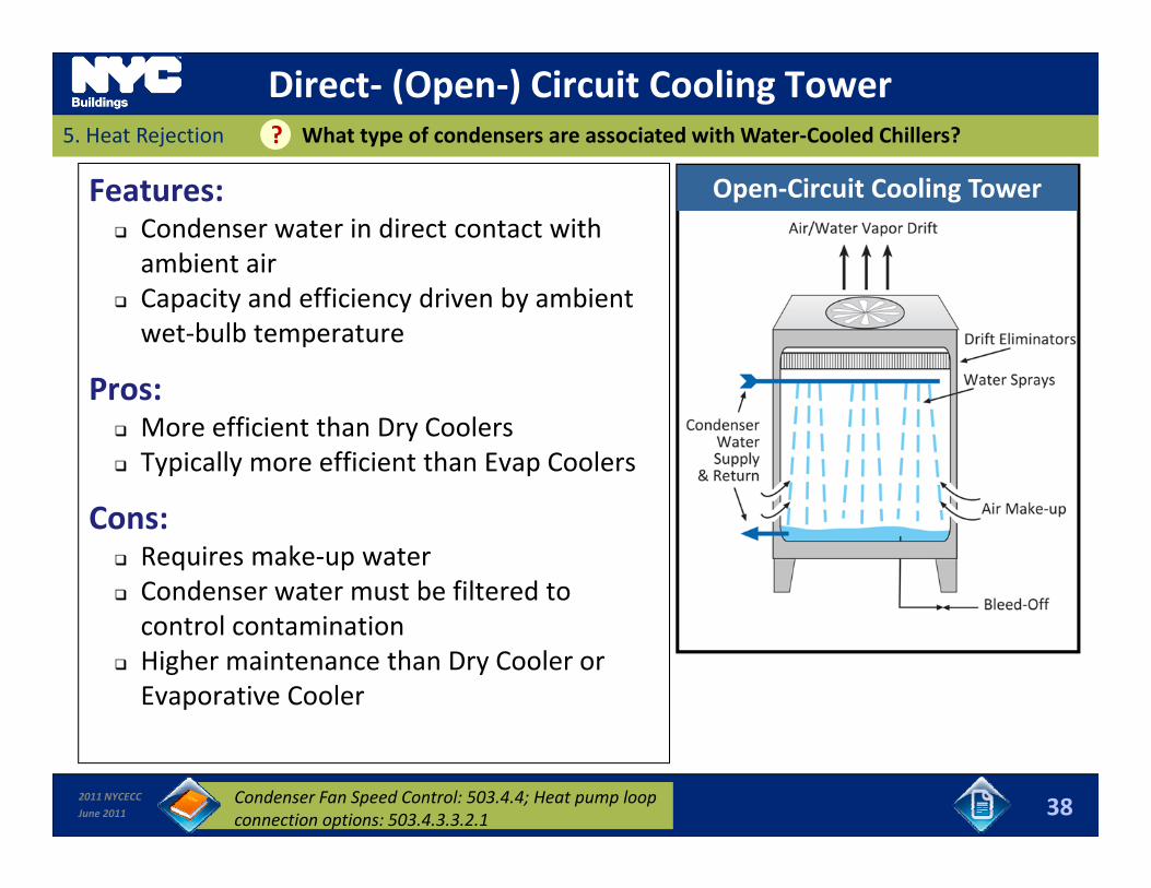
Direct‐ (Open‐) Circuit Cooling Tower5. Heat Rejection What type of condensers are associated with Water‐Cooled Chillers??
Features: Condenser water in direct contact with ambient air
Open‐Circuit Cooling Tower
Capacity and efficiency driven by ambient wet‐bulb temperature
Pros:Pros: More efficient than Dry Coolers Typically more efficient than Evap Coolers
Cons: Requires make‐up water Condenser water must be filtered to control contamination
Higher maintenance than Dry Cooler or Evaporative Cooler
2011 NYCECC
June 2011 38Condenser Fan Speed Control: 503.4.4; Heat pump loop connection options: 503.4.3.3.2.1
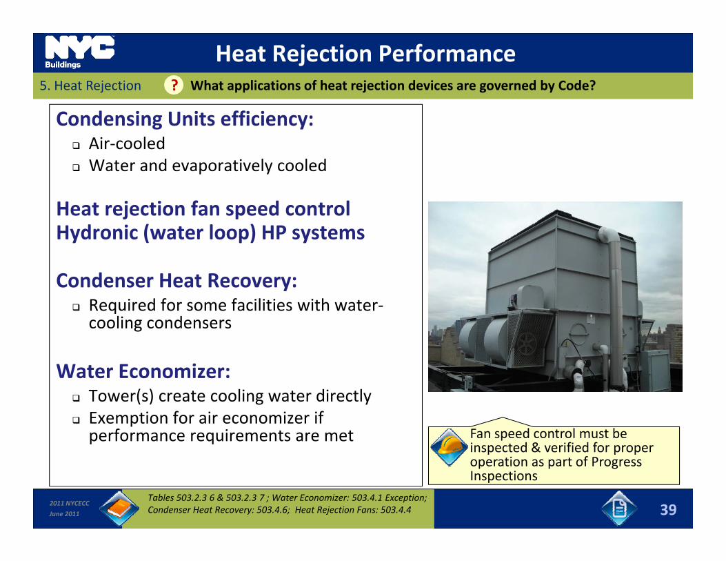
Heat Rejection Performance5. Heat Rejection What applications of heat rejection devices are governed by Code??
Condensing Units efficiency: Air‐cooled Water and evaporatively cooled
Heat rejection fan speed controlHydronic (water loop) HP systems
Condenser Heat Recovery: Required for some facilities with water‐
l dcooling condensers
Water Economizer: Tower(s) create cooling water directly Exemption for air economizer if performance requirements are met Fan speed control must be
inspected & verified for proper i f P
2011 NYCECC
June 2011 39Tables 503.2.3 6 & 503.2.3 7 ; Water Economizer: 503.4.1 Exception; Condenser Heat Recovery: 503.4.6; Heat Rejection Fans: 503.4.4
operation as part of Progress Inspections
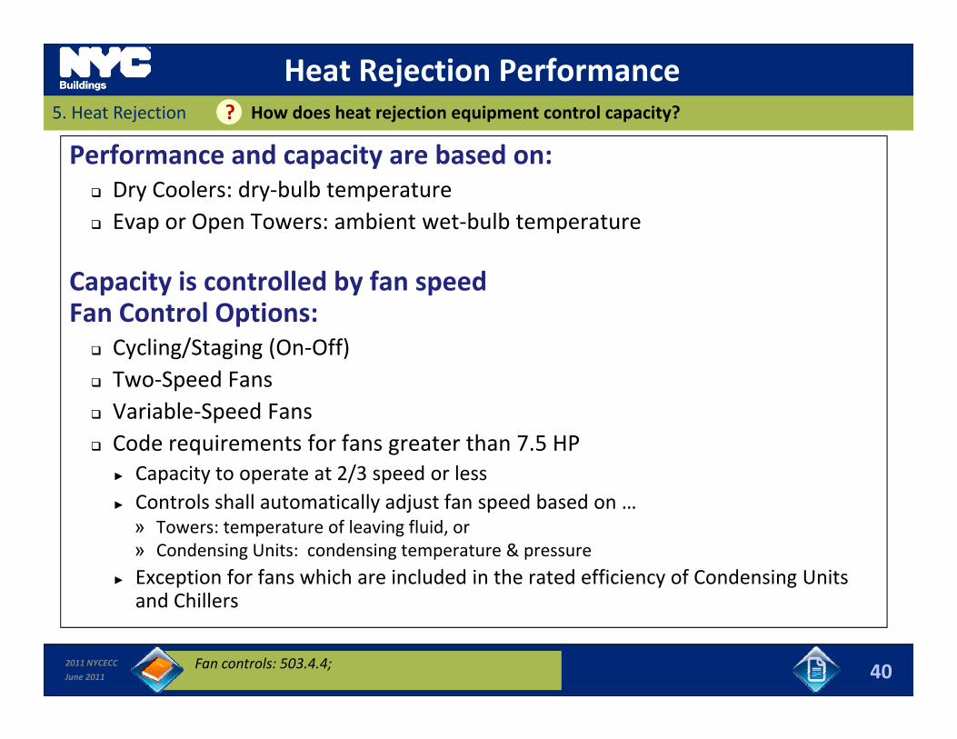
Heat Rejection Performance5. Heat Rejection How does heat rejection equipment control capacity??
Performance and capacity are based on: Dry Coolers: dry‐bulb temperature Evap or Open Towers: ambient wet‐bulb temperaturep p p
Capacity is controlled by fan speed Fan Control Options:p Cycling/Staging (On‐Off) Two‐Speed Fans Variable‐Speed Fans Variable Speed Fans Code requirements for fans greater than 7.5 HP
► Capacity to operate at 2/3 speed or less► Controls shall automatically adjust fan speed based on …y j p» Towers: temperature of leaving fluid, or» Condensing Units: condensing temperature & pressure
► Exception for fans which are included in the rated efficiency of Condensing Units and Chillers
2011 NYCECC
June 2011
and Chillers
40Fan controls: 503.4.4;
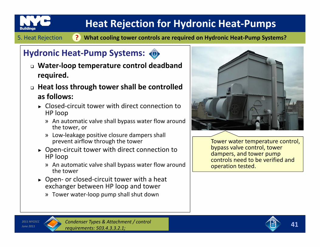
Heat Rejection for Hydronic Heat‐Pumps5. Heat Rejection What cooling tower controls are required on Hydronic Heat‐Pump Systems??
Hydronic Heat‐Pump Systems: Water‐loop temperature control deadbandrequired.required.
Heat loss through tower shall be controlled as follows:► Closed‐circuit tower with direct connection to► Closed circuit tower with direct connection to HP loop» An automatic valve shall bypass water flow around
the tower, or » Low‐leakage positive closure dampers shall
i fl h h h lprevent airflow through the tower► Open‐circuit tower with direct connection to HP loop» An automatic valve shall bypass water flow around
the tower
Tower water temperature control, bypass valve control, tower dampers, and tower pump controls need to be verified and operation tested.
the tower► Open‐ or closed‐circuit tower with a heat exchanger between HP loop and tower» Tower water‐loop pump shall shut down
2011 NYCECC
June 2011 41Condenser Types & Attachment / control requirements: 503.4.3.3.2.1;
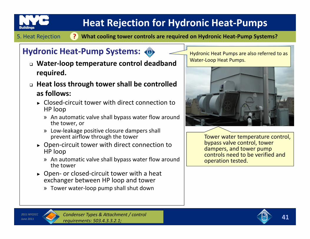
Heat Rejection for Hydronic Heat‐Pumps5. Heat Rejection What cooling tower controls are required on Hydronic Heat‐Pump Systems??
Hydronic Heat‐Pump Systems: Water‐loop temperature control deadbandrequired.
Hydronic Heat Pumps are also referred to as Water‐Loop Heat Pumps.
required.
Heat loss through tower shall be controlled as follows:► Closed‐circuit tower with direct connection to► Closed circuit tower with direct connection to HP loop» An automatic valve shall bypass water flow around
the tower, or » Low‐leakage positive closure dampers shall
i fl h h h lprevent airflow through the tower► Open‐circuit tower with direct connection to HP loop» An automatic valve shall bypass water flow around
the tower
Tower water temperature control, bypass valve control, tower dampers, and tower pump controls need to be verified and operation tested.
the tower► Open‐ or closed‐circuit tower with a heat exchanger between HP loop and tower» Tower water‐loop pump shall shut down
2011 NYCECC
June 2011 41Condenser Types & Attachment / control requirements: 503.4.3.3.2.1;
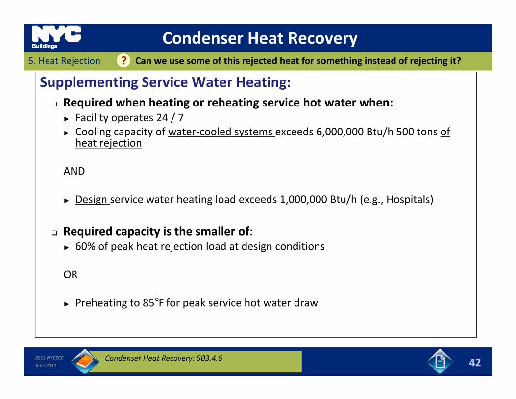
Condenser Heat Recovery5. Heat Rejection Can we use some of this rejected heat for something instead of rejecting it? ?
Supplementing Service Water Heating: Required when heating or reheating service hot water when:
► Facility operates 24 / 7► Cooling capacity of water‐cooled systems exceeds 6,000,000 Btu/h 500 tons of heat rejection
ANDAND
► Design service water heating load exceeds 1,000,000 Btu/h (e.g., Hospitals)
Required capacity is the smaller of: ► 60% of peak heat rejection load at design conditions
OROR
► Preheating to 85°F for peak service hot water draw
2011 NYCECC
June 2011 42Condenser Heat Recovery: 503.4.6
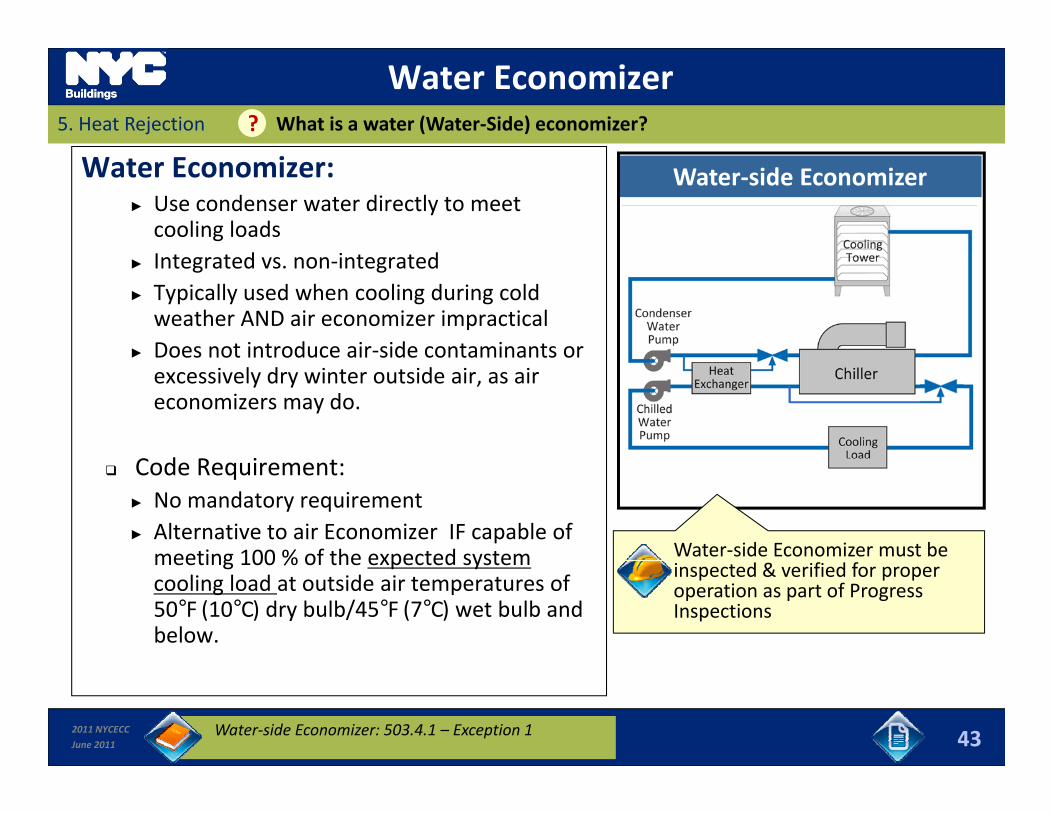
Water Economizer5. Heat Rejection What is a water (Water‐Side) economizer? ?
Water Economizer:► Use condenser water directly to meet cooling loads
d i d
Water‐side Economizer
► Integrated vs. non‐integrated ► Typically used when cooling during cold weather AND air economizer impractical
► Does not introduce air‐side contaminants or► Does not introduce air side contaminants or excessively dry winter outside air, as air economizers may do.
d i Code Requirement:► No mandatory requirement► Alternative to air Economizer IF capable of meeting 100 % of the expected system Water‐side Economizer must be meeting 100 % of the expected system cooling load at outside air temperatures of 50°F (10°C) dry bulb/45°F (7°C) wet bulb and below.
inspected & verified for proper operation as part of Progress Inspections
2011 NYCECC
June 2011 43Water‐side Economizer: 503.4.1 – Exception 1
6. Hydronic Systems & ControlsSlides 44 to 50 Learning Objectives
In this section you will learn about:
Schematics, pros, cons and requirements for Two‐pipe systems, Three‐pipe systems Hydronic Heat Pump loop Primary /Three pipe systems, Hydronic Heat Pump loop, Primary / Secondary Loops;
Part‐load control requirements including control valve types, Part load control requirements including control valve types, pump speed controls and temperature based reset controls; and
Pump control requirements.p q
2011 NYCECC
June 2011 44
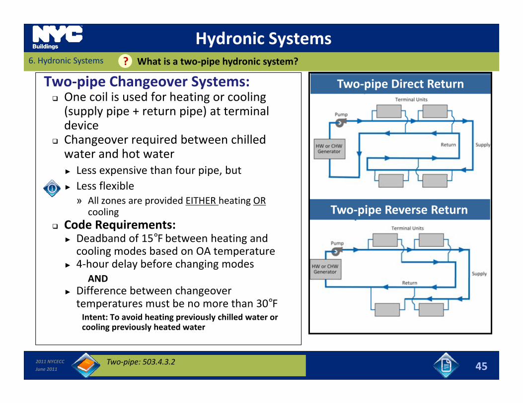
Hydronic Systems6. Hydronic Systems What is a two‐pipe hydronic system? ?
Two‐pipe Changeover Systems: One coil is used for heating or cooling (supply pipe + return pipe) at terminal device
Two‐pipe Direct Return
device Changeover required between chilled water and hot water ► Less expensive than four pipe, but ► Less flexible» All zones are provided EITHER heating OR
cooling Code Requirements:
Two‐pipe Reverse Return Code Requirements:
► Deadband of 15°F between heating and cooling modes based on OA temperature
► 4‐hour delay before changing modesANDAND
► Difference between changeover temperatures must be no more than 30°FIntent: To avoid heating previously chilled water or cooling previously heated water
2011 NYCECC
June 2011
cooling previously heated water
45Two‐pipe: 503.4.3.2
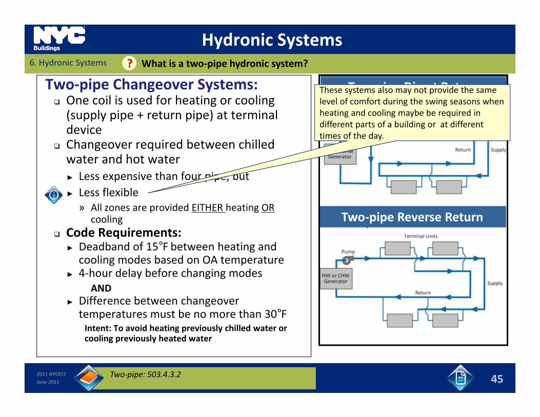
Hydronic Systems6. Hydronic Systems What is a two‐pipe hydronic system? ?
Two‐pipe Changeover Systems: One coil is used for heating or cooling (supply pipe + return pipe) at terminal device
Two‐pipe Direct ReturnThese systems also may not provide the same level of comfort during the swing seasons when heating and cooling maybe be required in different parts of a building or at different device
Changeover required between chilled water and hot water ► Less expensive than four pipe, but
times of the day.
► Less flexible» All zones are provided EITHER heating OR
cooling Code Requirements:
Two‐pipe Reverse Return Code Requirements:
► Deadband of 15°F between heating and cooling modes based on OA temperature
► 4‐hour delay before changing modesANDAND
► Difference between changeover temperatures must be no more than 30°FIntent: To avoid heating previously chilled water or cooling previously heated water
2011 NYCECC
June 2011
cooling previously heated water
45Two‐pipe: 503.4.3.2
Hydronic Systems6. Hydronic Systems What is a three‐pipe hydronic system? ?
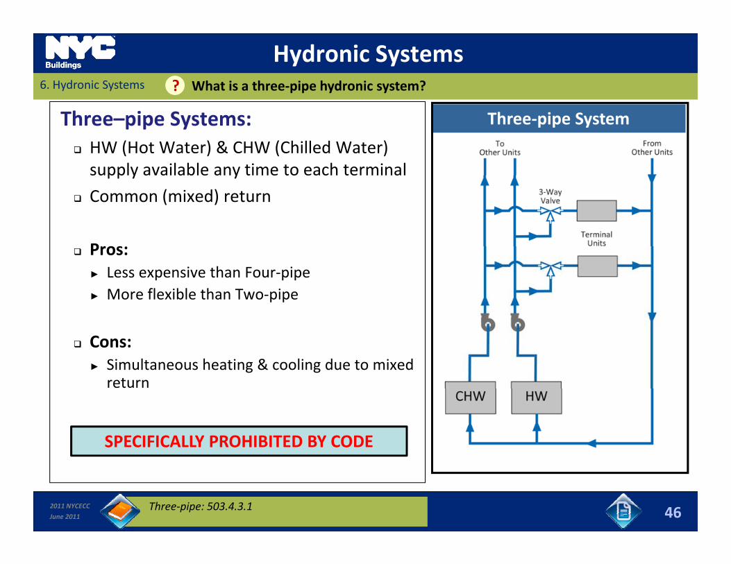
Three–pipe Systems: HW (Hot Water) & CHW (Chilled Water) supply available any time to each terminal
Three‐pipe System
supp y a a ab e a y e o eac e a
Common (mixed) return
Pros: Pros:► Less expensive than Four‐pipe► More flexible than Two‐pipe
Cons:► Simultaneous heating & cooling due to mixed return
SPECIFICALLY PROHIBITED BY CODE
2011 NYCECC
June 2011 46Three‐pipe: 503.4.3.1
Hydronic Systems6. Hydronic Systems What is a water‐source heat‐pump loop? ?
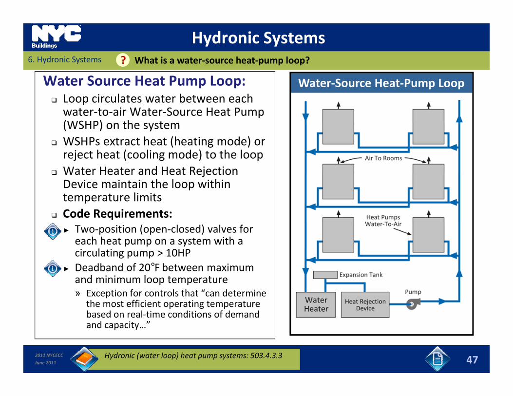
Water Source Heat Pump Loop: Loop circulates water between each water‐to‐air Water‐Source Heat Pump (WSHP) on the system
Water‐Source Heat‐Pump Loop
(WSHP) on the system WSHPs extract heat (heating mode) or reject heat (cooling mode) to the loop
Water Heater and Heat Rejection Water Heater and Heat Rejection Device maintain the loop within temperature limits
Code Requirements:► Two‐position (open‐closed) valves for each heat pump on a system with a circulating pump > 10HP
► Deadband of 20°F between maximum and minimum loop temperature» Exception for controls that “can determine
the most efficient operating temperature based on real‐time conditions of demand d it ”
2011 NYCECC
June 2011
and capacity…”
47Hydronic (water loop) heat pump systems: 503.4.3.3
Hydronic Systems6. Hydronic Systems What is a water‐source heat‐pump loop? ?
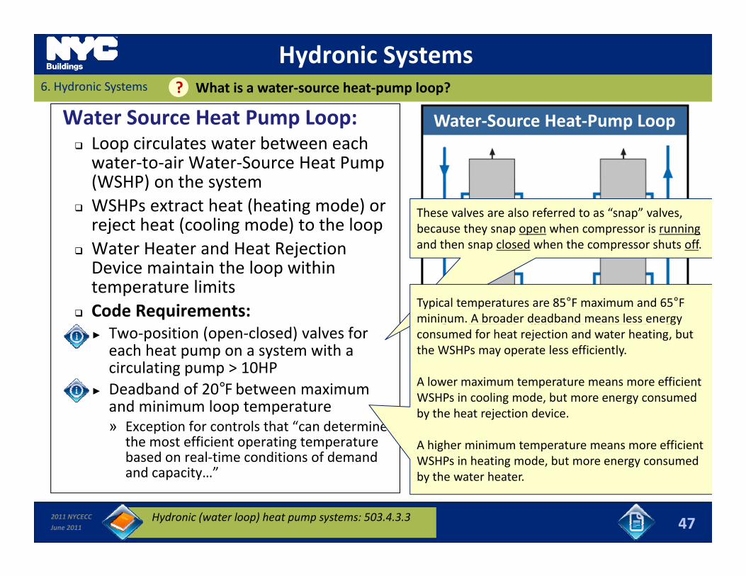
Water Source Heat Pump Loop: Loop circulates water between each water‐to‐air Water‐Source Heat Pump (WSHP) on the system
Water‐Source Heat‐Pump Loop
(WSHP) on the system WSHPs extract heat (heating mode) or reject heat (cooling mode) to the loop
Water Heater and Heat Rejection
These valves are also referred to as “snap” valves, because they snap open when compressor is runningand then snap closed when the compressor shuts off.
Water Heater and Heat Rejection Device maintain the loop within temperature limits
Code Requirements: Typical temperatures are 85°F maximum and 65°F mininum. A broader deadband means less energy
► Two‐position (open‐closed) valves for each heat pump on a system with a circulating pump > 10HP
► Deadband of 20°F between maximum
gyconsumed for heat rejection and water heating, but the WSHPs may operate less efficiently.
A lower maximum temperature means more efficient WSHPs in cooling mode but more energy consumed
and minimum loop temperature» Exception for controls that “can determine
the most efficient operating temperature based on real‐time conditions of demand d it ”
WSHPs in cooling mode, but more energy consumed by the heat rejection device.
A higher minimum temperature means more efficient WSHPs in heating mode, but more energy consumed
2011 NYCECC
June 2011
and capacity…”
47
by the water heater.
Hydronic (water loop) heat pump systems: 503.4.3.3

Hydronic SystemsWhat are heating and cooling plant requirements??6. Hydronic Systems
Chiller and Boiler Plants: Part‐Load Control for plants > 300,000 Btu/h design output capacity
Reset supply water temp by 25% of design► Reset supply water temp. by 25% of design temp. difference based on return water OR outside air temperature.
► Reduce pump flow by 50% automatically using:» Adjustable speed pumps
Isolation Valves, two‐position valves, temperature reset sequences, pump
» Adjustable speed pumpsOR» Multi‐staged pumps that reduce total pump
horsepower by at least 50%
Multiple boilers, and chillers in parallel temperature reset sequences, pump control strategy must be shown on drawings. A minimum sample of 20% must be inspected/tested.
► Automatic controls that reduce plant flow when a chiller/boiler turns off
Boiler Plant Specific Requirements:► Multiple‐packaged boiler plants must have► Multiple packaged boiler plants must have
controls that automatically sequence the boiler operation; and
► Single boiler plants > 500,000 Btu/h design input capacity must have a multi‐staged or
2011 NYCECC
June 2011
input capacity must have a multi staged or modulating burner
48Pump Isolation: 503.4.3.5; Part load controls: 503.4.3.4
Hydronic SystemsWhat are heating and cooling plant requirements??6. Hydronic Systems
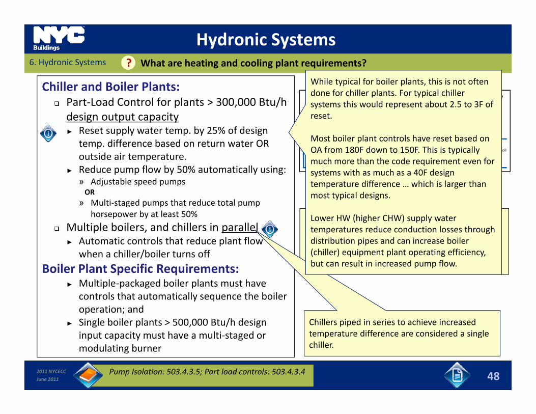
Chiller and Boiler Plants: Part‐Load Control for plants > 300,000 Btu/h design output capacity
Reset supply water temp by 25% of design
While typical for boiler plants, this is not often done for chiller plants. For typical chiller systems this would represent about 2.5 to 3F of reset.
► Reset supply water temp. by 25% of design temp. difference based on return water OR outside air temperature.
► Reduce pump flow by 50% automatically using:» Adjustable speed pumps
Most boiler plant controls have reset based on OA from 180F down to 150F. This is typically much more than the code requirement even for systems with as much as a 40F design
diff hi h i l h
Isolation Valves, two‐position valves, temperature reset sequences, pump
» Adjustable speed pumpsOR» Multi‐staged pumps that reduce total pump
horsepower by at least 50%
Multiple boilers, and chillers in parallel
temperature difference … which is larger than most typical designs.
Lower HW (higher CHW) supply water temperatures reduce conduction losses through temperature reset sequences, pump
control strategy must be shown on drawings. A minimum sample of 20% must be inspected/tested.
► Automatic controls that reduce plant flow when a chiller/boiler turns off
Boiler Plant Specific Requirements:► Multiple‐packaged boiler plants must have
p gdistribution pipes and can increase boiler (chiller) equipment plant operating efficiency, but can result in increased pump flow.
► Multiple packaged boiler plants must have controls that automatically sequence the boiler operation; and
► Single boiler plants > 500,000 Btu/h design input capacity must have a multi‐staged or
Chillers piped in series to achieve increased temperature difference are considered a single
2011 NYCECC
June 2011
input capacity must have a multi staged or modulating burner
48Pump Isolation: 503.4.3.5; Part load controls: 503.4.3.4
p gchiller.
Hydronic Systems6. Hydronic Systems How is flow controlled by pumps in a Hydronic Loop??
Pump Speed Controls: Constant Speed Pump Motor
► Provide constant flow at constant input powerMultiple pumps in parallel can be staged
Pump Laws/Formulas
Pump Speed Water FlowWater Pressure (Water Flow)2► Multiple pumps in parallel can be staged
on/off to achieve variable flow control 2‐Speed Pumps
► Provide constant flow at each speedP d h hi i bl fl
Water Pressure (Water Flow)2
Water Power (Water Flow)3
Flow x Pressure Pump Power Pump Efficiency► Pump speed changes to achieve variable flow control ‐ based on pressure ranges or flow measurements
Variable Speed Pumps
Pump Efficiency
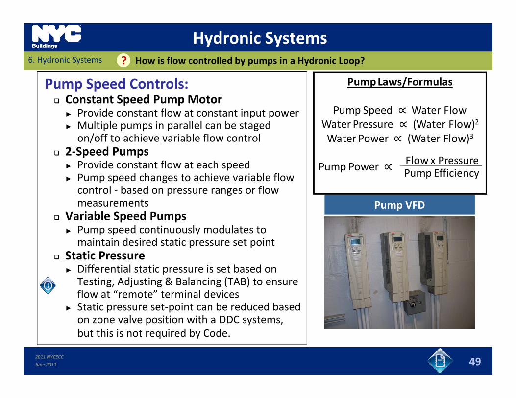
Pump VFD
► Pump speed continuously modulates to maintain desired static pressure set point
Static Pressure► Differential static pressure is set based on pTesting, Adjusting & Balancing (TAB) to ensure flow at “remote” terminal devices
► Static pressure set‐point can be reduced based on zone valve position with a DDC systems,
2011 NYCECC
June 2011
p y ,but this is not required by Code.
49
Hydronic Systems6. Hydronic Systems How is flow controlled by pumps in a Hydronic Loop??
Pump Speed Controls: Constant Speed Pump Motor
► Provide constant flow at constant input powerMultiple pumps in parallel can be staged
Pump Laws/Formulas
Pump Speed Water FlowWater Pressure (Water Flow)2► Multiple pumps in parallel can be staged
on/off to achieve variable flow control 2‐Speed Pumps
► Provide constant flow at each speedP d h hi i bl fl
Water Pressure (Water Flow)2
Water Power (Water Flow)3
Flow x Pressure Pump Power Pump Efficiency► Pump speed changes to achieve variable flow control ‐ based on pressure ranges or flow measurements
Variable Speed Pumps
Pump Efficiency
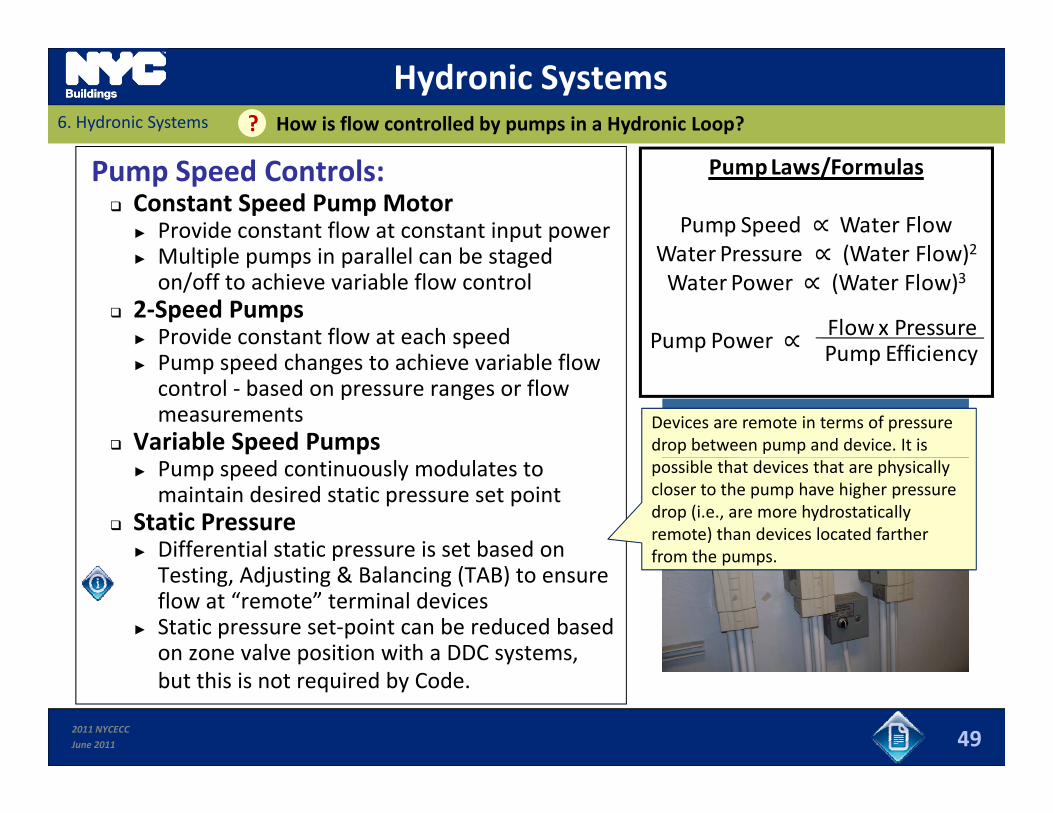
Pump VFDDevices are remote in terms of pressure drop between pump and device. It is
► Pump speed continuously modulates to maintain desired static pressure set point
Static Pressure► Differential static pressure is set based on
possible that devices that are physically closer to the pump have higher pressure drop (i.e., are more hydrostatically remote) than devices located farther from the pumps.p
Testing, Adjusting & Balancing (TAB) to ensure flow at “remote” terminal devices
► Static pressure set‐point can be reduced based on zone valve position with a DDC systems,
from the pumps.
2011 NYCECC
June 2011
p y ,but this is not required by Code.
49
Hydronic System Controls6. Hydronic Systems How is flow controlled at Terminal Units in a Hydronic Loop??
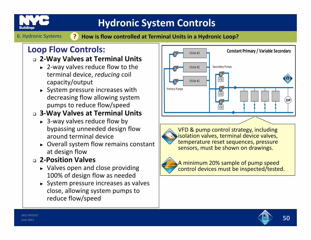
Loop Flow Controls: 2‐Way Valves at Terminal Units
► 2‐way valves reduce flow to the terminal device reducing coilterminal device, reducing coil capacity/output
► System pressure increases with decreasing flow allowing system pumps to reduce flow/speed
DP
VFD & pump control strategy, including isolation valves terminal device valves
pumps to reduce flow/speed 3‐Way Valves at Terminal Units
► 3‐way valves reduce flow by bypassing unneeded design flow
d t i l d i isolation valves, terminal device valves, temperature reset sequences, pressure sensors, must be shown on drawings.
A minimum 20% sample of pump speed
around terminal device► Overall system flow remains constant
at design flow 2‐Position Valves
l d l idip p p p
control devices must be inspected/tested.► Valves open and close providing 100% of design flow as needed
► System pressure increases as valves close, allowing system pumps to d fl / d
2011 NYCECC
June 2011
reduce flow/speed
50
Hydronic System Controls6. Hydronic Systems How is flow controlled at Terminal Units in a Hydronic Loop??
Loop Flow Controls: 2‐Way Valves at Terminal Units
► 2‐way valves reduce flow to the terminal device reducing coilterminal device, reducing coil capacity/output
► System pressure increases with decreasing flow allowing system pumps to reduce flow/speed
DP
VFD & pump control strategy, including isolation valves terminal device valves
pumps to reduce flow/speed 3‐Way Valves at Terminal Units
► 3‐way valves reduce flow by bypassing unneeded design flow
d t i l d i isolation valves, terminal device valves, temperature reset sequences, pressure sensors, must be shown on drawings.
A minimum 20% sample of pump speed
around terminal device► Overall system flow remains constant
at design flow 2‐Position Valves
l d l idi
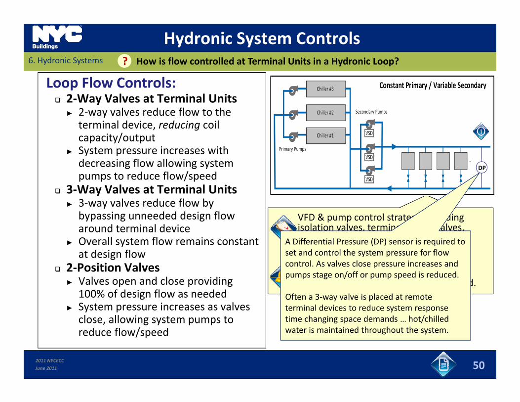
A Differential Pressure (DP) sensor is required to set and control the system pressure for flow control. As valves close pressure increases and pumps stage on/off or pump speed is reduced.p p p p
control devices must be inspected/tested.► Valves open and close providing 100% of design flow as needed
► System pressure increases as valves close, allowing system pumps to d fl / d
pumps stage on/off or pump speed is reduced.
Often a 3‐way valve is placed at remote terminal devices to reduce system response time changing space demands … hot/chilled
t i i t i d th h t th t
2011 NYCECC
June 2011
reduce flow/speed
50
water is maintained throughout the system.
7. Service Hot WaterSlides 51 to 55 Sub‐Module Overview
In this section you will learn about:
Performance Requirements;
Control Requirements; Control Requirements;► Temperature► Heat Traps► Hot Water System Controlsy
Pipe Insulation; and
Swimming Pools.
2011 NYCECC
June 2011 51
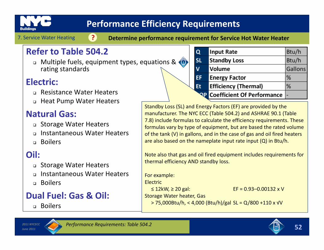
Performance Efficiency Requirements7. Service Water Heating Determine performance requirement for Service Hot Water Heater?
Refer to Table 504.2 Multiple fuels, equipment types, equations &
rating standards
Electric: Resistance Water Heaters Heat Pump Water Heaters
Standby Loss (SL) and Energy Factors (EF) are provided by the
Natural Gas: Storage Water Heaters Instantaneous Water Heaters
Boilers
manufacturer. The NYC ECC (Table 504.2) and ASHRAE 90.1 (Table 7.8) include formulas to calculate the efficiency requirements. These formulas vary by type of equipment, but are based the rated volume of the tank (V) in gallons, and in the case of gas and oil fired heaters are also based on the nameplate input rate input (Q) in Btu/h Boilers
Oil: Storage Water Heaters
I t t W t H t
are also based on the nameplate input rate input (Q) in Btu/h.
Note also that gas and oil fired equipment includes requirements for thermal efficiency AND standby loss.
Instantaneous Water Heaters Boilers
Dual Fuel: Gas & Oil:B il
For example:Electric
≤ 12kW, ≥ 20 gal: EF = 0.93–0.00132 x VStorage Water heater, Gas
> 75,000Btu/h, < 4,000 (Btu/h)/gal SL = Q/800 +110 x √V
2011 NYCECC
June 2011
Boilers
52Performance Requirements: Table 504.2
> 75,000Btu/h, < 4,000 (Btu/h)/gal SL Q/800 +110 x √V
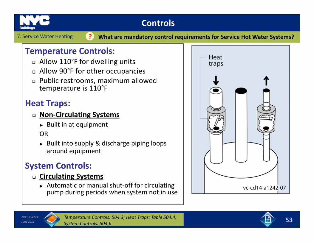
Controls7. Service Water Heating What are mandatory control requirements for Service Hot Water Systems??
Temperature Controls: Allow 110°F for dwelling units Allow 90°F for other occupancies Public restrooms, maximum allowed temperature is 110°F
Heat Traps:Heat Traps: Non‐Circulating Systems
► Built in at equipmentOR► Built into supply & discharge piping loops around equipment
System Controls:System Controls: Circulating Systems
► Automatic or manual shut‐off for circulating pump during periods when system not in use
2011 NYCECC
June 2011 53Temperature Controls: 504.3; Heat Traps: Table 504.4; System Controls: 504.6

Insulation Requirements7. Service Water Heating Which components need to be insulated in Service Hot Water Systems??
Pipe Insulation: Circulating systems:
► 1 in thickness► 1 in. thickness
Non‐circulating systems:► ½ in. thickness for first 8 feet if there are no integral heat traps with heater
(Insulation thickness based on conductivity 0.27 Btu‐in. /h‐ft2‐°F or less)y
Unfired Storage Tanks Insulation: R‐12.5 or higher
Swimming Pool Cover: All heated pools
► Vapor‐retardant cover installed at or on water surfacep
Pools heated to over 90°F► Cover shall be R‐12 or higher
Version 2 542011 NYCECC
June 2011 54Pipe Insulation: 504.5; Pool Covers: 504.7.3
Swimming Pools7. Service Water Heating What are requirements in commercial buildings for swimming pools??
Pool: Heater Performance
► Gas‐ or oil‐fired heaters: 78% Et
► Heat Pump heaters: 4.0 COP
► Continuously burning pilots prohibited
Heater and Pump Controls Heater and Pump Controls► Heater to have readily accessible on‐off control independent of thermostat setting
► Automatic time switches must be installed on heater and pumps» Exceptions:» Exceptions: Public health standards require 24‐hour pump operation
Pumps required to operate for solar or site‐recovered heat
2011 NYCECC
June 2011 55Swimming Pools: 504.7;
Slides 56 to 83 8. Submissions & InspectionsBuilding HVAC and Service Hot Water (SHW)
2011 NYCECC
June 2011 56
Photo: US DOE Building Energy Codes University
8. Submissions & InspectionsLearning Objectives
In this section you will learn about:
HVAC‐ and SHW‐related requirements for NYCECC Submissions, including:► Energy Analysis, and
► Supporting Documentation
Applicable Progress Inspections associated with HVAC and SHW Systems.
2011 NYCECC
June 2011 57
NYCECC and ApplicationsWhat are the application requirements related to the NYCECC??8. Submissions & Inspections
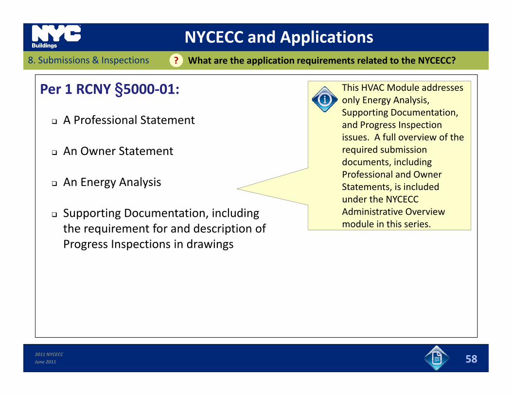
Per 1 RCNY §5000‐01:
A Professional Statement
This HVAC Module addresses only Energy Analysis, Supporting Documentation, d P I ti A Professional Statement
An Owner Statement
and Progress Inspection issues. A full overview of the required submission documents, including Professional and O ner
An Energy Analysis
Supporting Documentation, including
Professional and Owner Statements, is included under the NYCECC Administrative Overview module in this seriesthe requirement for and description of
Progress Inspections in drawings
module in this series.
2011 NYCECC
June 2011 58
Energy AnalysisWhat types of Energy Analysis are allowed??8. Submissions & Inspections
Per 1 RCNY §5000‐01:
Tabular Analysisy
COMcheck software
Energy Modeling
Alternative Formats
2011 NYCECC
June 2011 59
Energy AnalysisHow Should HVAC and SWH Systems be addressed in the Energy Analysis??8. Submissions & Inspections
Option 1: Tabular Analysis
The Tabular Analysis compares proposed values of each ECC‐regulated item fin the scope of work with the respective prescriptive values required by the
Code.► Applicable to New Buildings, Additions, or Alterations
► Demonstrates Prescriptive Compliance
► Can be used with either NYCECC or ASHRAE 90.1
2011 NYCECC
June 2011 60

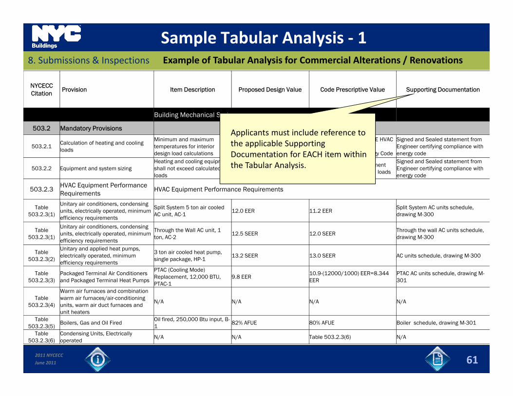
Sample Tabular Analysis ‐ 1Example of Tabular Analysis for Commercial Alterations / Renovations8. Submissions & Inspections
NYCECCCitation
Provision Item Description Proposed Design Value Code Prescriptive Value Supporting Documentation
Building Mechanical Systems
503.2 Mandatory Provisions
503.2.1Calculation of heating and cooling loads
Minimum and maximum temperatures for interior design load calculations
N/AASHRAE/ACCA 183 ASHRAE HVAC Systems and Equipment Handbook, chapter 3 Energy Code
Signed and Sealed statement from Engineer certifying compliance with energy code
503.2.2 Equipment and system sizingHeating and cooling equipment shall not exceed calculated
Heating and cooling equipment shall not exceed calculated loads
Signed and Sealed statement from Engineer certifying compliance with
loadsshall not exceed calculated loads
energy code
503.2.3HVAC Equipment Performance Requirements
HVAC Equipment Performance Requirements
Table 503.2.3(1)
Unitary air conditioners, condensing units, electrically operated, minimum efficiency requirements
Split System 5 ton air cooled AC unit, AC-1
12.0 EER 11.2 EERSplit System AC units schedule, drawing M-300
Table 503.2.3(1)
Unitary air conditioners, condensing units, electrically operated, minimum efficiency requirements
Through the Wall AC unit, 1 ton, AC-2
12.5 SEER 12.0 SEERThrough the wall AC units schedule, drawing M-300
Table 503.2.3(2)
Unitary and applied heat pumps, electrically operated, minimum efficiency requirements
3 ton air cooled heat pump, single package, HP-1
13.2 SEER 13.0 SEER AC units schedule, drawing M-300
Table Packaged Terminal Air Conditioners PTAC (Cooling Mode)
10 9 (12000/1000) EER=8 344 PTAC AC units schedule drawing MTable 503.2.3(3)
Packaged Terminal Air Conditioners and Packaged Terminal Heat Pumps
Replacement, 12,000 BTU, PTAC-1
9.8 EER10.9-(12000/1000) EER=8.344 EER
PTAC AC units schedule, drawing M-301
Table 503.2.3(4)
Warm air furnaces and combination warm air furnaces/air-conditioning units, warm air duct furnaces and unit heaters
N/A N/A N/A N/A
Table Boilers Gas and Oil Fired
Oil fired, 250,000 Btu input, B-82% AFUE 80% AFUE Boiler schedule drawing M 301
2011 NYCECC
June 2011
503.2.3(5)Boilers, Gas and Oil Fired
182% AFUE 80% AFUE Boiler schedule, drawing M-301
Table 503.2.3(6)
Condensing Units, Electrically operated
N/A N/A Table 503.2.3(6) N/A
61
Sample Tabular Analysis ‐ 1Example of Tabular Analysis for Commercial Alterations / Renovations8. Submissions & Inspections
NYCECCCitation
Provision Item Description Proposed Design Value Code Prescriptive Value Supporting Documentation
Building Mechanical Systems
503.2 Mandatory Provisions
503.2.1Calculation of heating and cooling loads
Minimum and maximum temperatures for interior design load calculations
N/AASHRAE/ACCA 183 ASHRAE HVAC Systems and Equipment Handbook, chapter 3 Energy Code
Signed and Sealed statement from Engineer certifying compliance with energy code
503.2.2 Equipment and system sizingHeating and cooling equipment shall not exceed calculated
Heating and cooling equipment shall not exceed calculated loads
Signed and Sealed statement from Engineer certifying compliance with
Applicants must include reference to the applicable Supporting Documentation for EACH item within the Tabular Analysis.
loadsshall not exceed calculated loads
energy code
503.2.3HVAC Equipment Performance Requirements
HVAC Equipment Performance Requirements
Table 503.2.3(1)
Unitary air conditioners, condensing units, electrically operated, minimum efficiency requirements
Split System 5 ton air cooled AC unit, AC-1
12.0 EER 11.2 EERSplit System AC units schedule, drawing M-300
Table 503.2.3(1)
Unitary air conditioners, condensing units, electrically operated, minimum efficiency requirements
Through the Wall AC unit, 1 ton, AC-2
12.5 SEER 12.0 SEERThrough the wall AC units schedule, drawing M-300
Table 503.2.3(2)
Unitary and applied heat pumps, electrically operated, minimum efficiency requirements
3 ton air cooled heat pump, single package, HP-1
13.2 SEER 13.0 SEER AC units schedule, drawing M-300
Table Packaged Terminal Air Conditioners PTAC (Cooling Mode)
10 9 (12000/1000) EER=8 344 PTAC AC units schedule drawing MTable 503.2.3(3)
Packaged Terminal Air Conditioners and Packaged Terminal Heat Pumps
Replacement, 12,000 BTU, PTAC-1
9.8 EER10.9-(12000/1000) EER=8.344 EER
PTAC AC units schedule, drawing M-301
Table 503.2.3(4)
Warm air furnaces and combination warm air furnaces/air-conditioning units, warm air duct furnaces and unit heaters
N/A N/A N/A N/A
Table Boilers Gas and Oil Fired
Oil fired, 250,000 Btu input, B-82% AFUE 80% AFUE Boiler schedule drawing M 301
2011 NYCECC
June 2011
503.2.3(5)Boilers, Gas and Oil Fired
182% AFUE 80% AFUE Boiler schedule, drawing M-301
Table 503.2.3(6)
Condensing Units, Electrically operated
N/A N/A Table 503.2.3(6) N/A
61
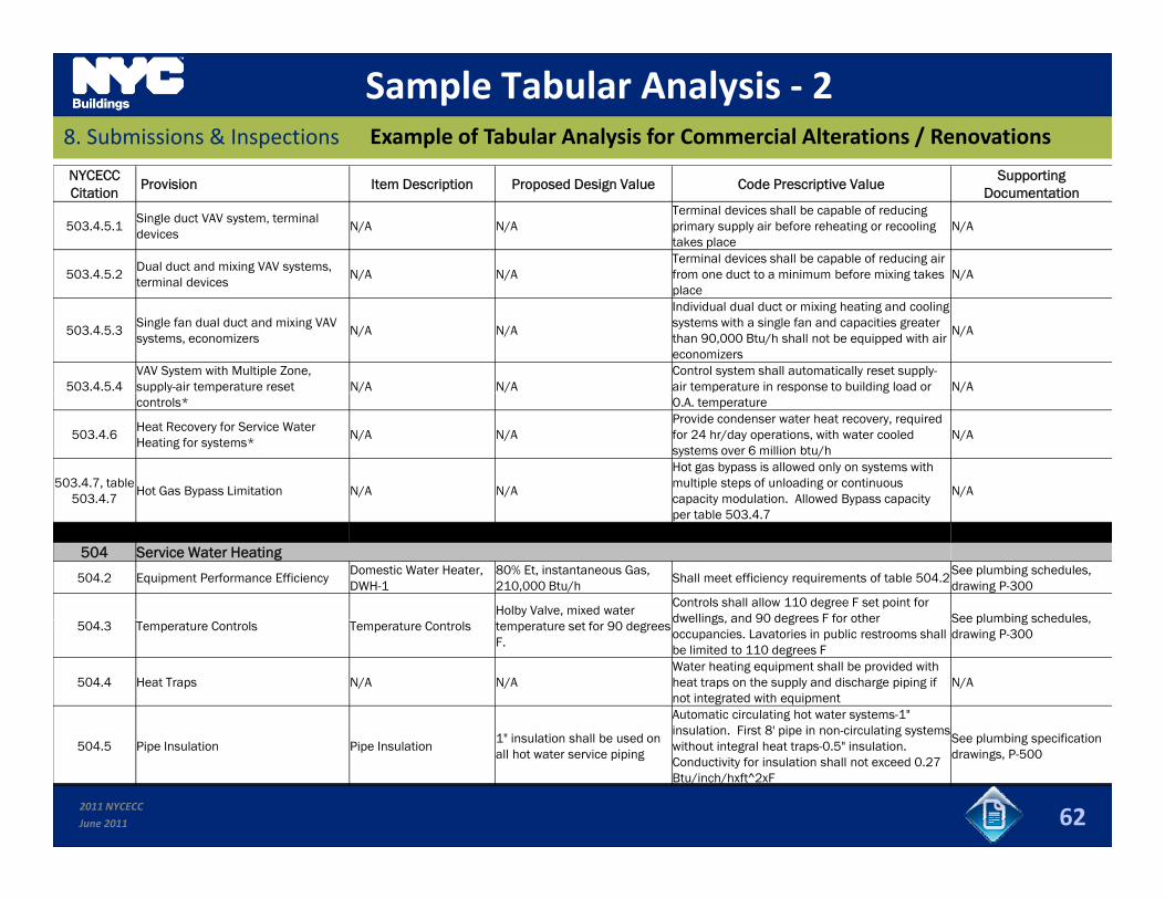
Sample Tabular Analysis ‐ 2Example of Tabular Analysis for Commercial Alterations / Renovations8. Submissions & Inspections
NYCECCCitation
Provision Item Description Proposed Design Value Code Prescriptive ValueSupporting
Documentation
503.4.5.1Single duct VAV system, terminal devices
N/A N/ATerminal devices shall be capable of reducing primary supply air before reheating or recooling takes place
N/A
503.4.5.2Dual duct and mixing VAV systems, t i l d i
N/A N/ATerminal devices shall be capable of reducing air from one duct to a minimum before mixing takes N/A
terminal devices/ / g
place/
503.4.5.3Single fan dual duct and mixing VAV systems, economizers
N/A N/A
Individual dual duct or mixing heating and cooling systems with a single fan and capacities greater than 90,000 Btu/h shall not be equipped with air economizers
N/A
503.4.5.4VAV System with Multiple Zone, supply-air temperature reset N/A N/A
Control system shall automatically reset supply-air temperature in response to building load or N/A
controls*g
O.A. temperature
503.4.6Heat Recovery for Service Water Heating for systems*
N/A N/AProvide condenser water heat recovery, required for 24 hr/day operations, with water cooled systems over 6 million btu/h
N/A
503.4.7, table 503.4.7
Hot Gas Bypass Limitation N/A N/A
Hot gas bypass is allowed only on systems with multiple steps of unloading or continuous capacity modulation. Allowed Bypass capacity
N/A
per table 503.4.7
504 Service Water Heating
504.2 Equipment Performance EfficiencyDomestic Water Heater, DWH-1
80% Et, instantaneous Gas, 210,000 Btu/h
Shall meet efficiency requirements of table 504.2See plumbing schedules, drawing P-300
Holby Valve, mixed water Controls shall allow 110 degree F set point for dwellings and 90 degrees F for other See plumbing schedules
504.3 Temperature Controls Temperature Controls temperature set for 90 degrees F.
dwellings, and 90 degrees F for other occupancies. Lavatories in public restrooms shall be limited to 110 degrees F
See plumbing schedules, drawing P-300
504.4 Heat Traps N/A N/AWater heating equipment shall be provided with heat traps on the supply and discharge piping if not integrated with equipment
N/A
Automatic circulating hot water systems-1" insulation. First 8' pipe in non-circulating systems
2011 NYCECC
June 2011 62
504.5 Pipe Insulation Pipe Insulation1" insulation shall be used on all hot water service piping
insulation. First 8 pipe in non circulating systems without integral heat traps-0.5" insulation. Conductivity for insulation shall not exceed 0.27 Btu/inch/hxft^2xF
See plumbing specification drawings, P-500
Energy AnalysisHow Should HVAC and SWH systems be Addressed in the Energy Analysis?8. Submissions & Inspections ?
Option 2: COMcheck submissions
COMcheck software, available for free from the US Department of Energy, can be used to prepare energy code compliance calculations. ► Lists all Mandatory and Prescriptive Compliance requirements related to HVAC and SHW
systems
O l N Y k St t NYCECC ASHRAE 90 1 COM h k f itt d ( t IECC)► Only New York State NYCECC or ASHRAE‐90.1 COMcheck forms are permitted (not IECC)
► Downloads: http://www.energycodes.gov/software.stm
2011 NYCECC
June 2011 63
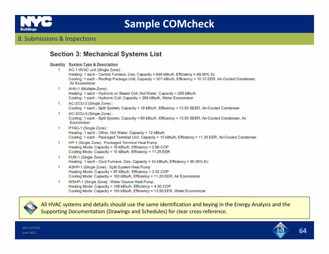
Sample COMcheck8. Submissions & Inspections
All HVAC systems and details should use the same identification and keying in the Energy Analysis and the
2011 NYCECC
June 2011
y y g gy ySupporting Documentation (Drawings and Schedules) for clear cross‐reference.
64
Energy AnalysisHow Should HVAC and SHW systems be Addressed in the Energy Analysis?8. Submissions & Inspections ?
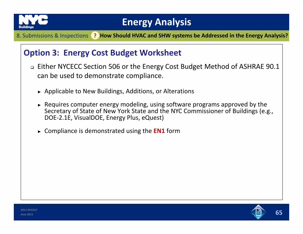
Option 3: Energy Cost Budget Worksheet
Either NYCECC Section 506 or the Energy Cost Budget Method of ASHRAE 90.1 can be used to demonstrate compliance.
► Applicable to New Buildings, Additions, or Alterations
R i d li i f d b h► Requires computer energy modeling, using software programs approved by the Secretary of State of New York State and the NYC Commissioner of Buildings (e.g., DOE‐2.1E, VisualDOE, Energy Plus, eQuest)
► Compliance is demonstrated using the EN1 form► Compliance is demonstrated using the EN1 form
2011 NYCECC
June 2011 65
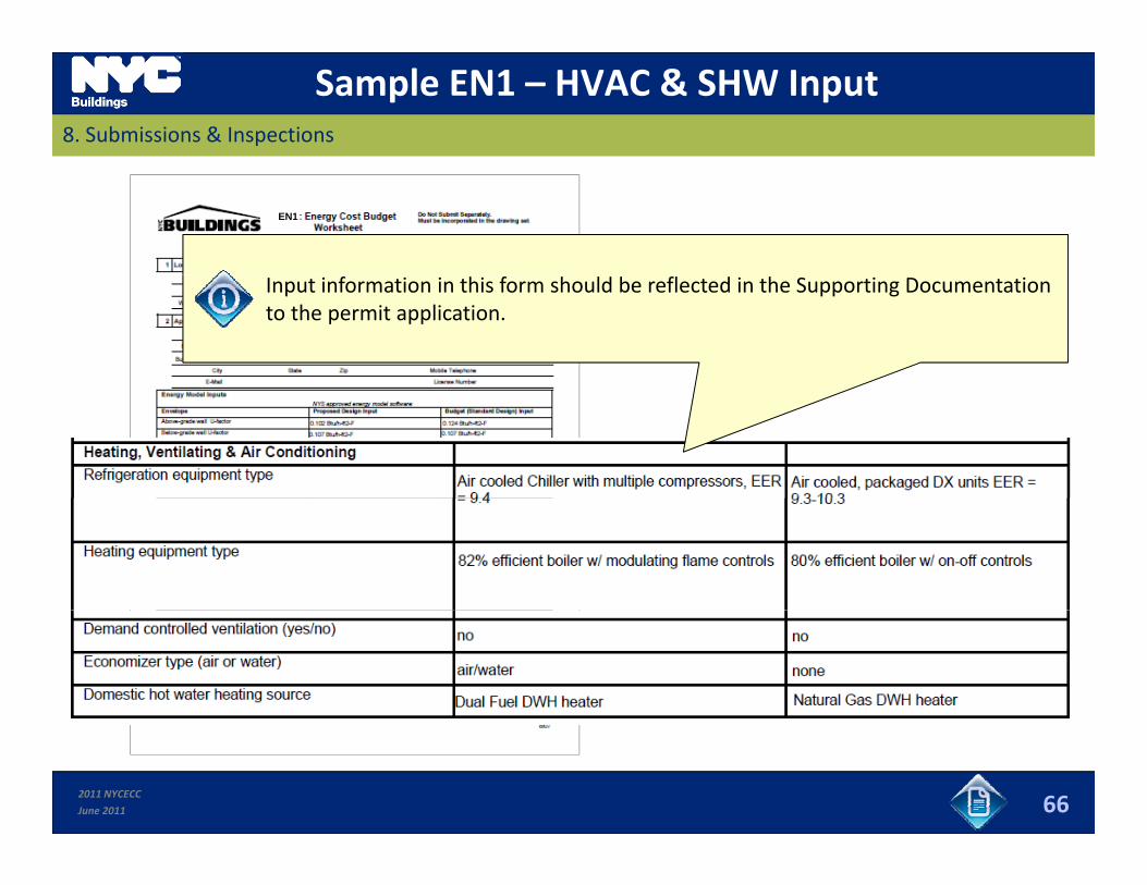
Sample EN1 – HVAC & SHW Input8. Submissions & Inspections
EN1
Input information in this form should be reflected in the Supporting Documentation to the permit application.
2011 NYCECC
June 2011 66
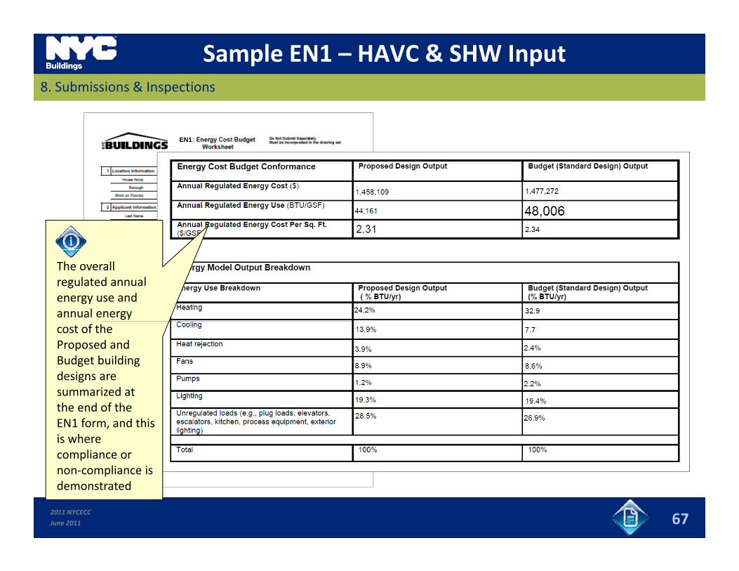
Sample EN1 – HAVC & SHW Input8. Submissions & Inspections
EN1
The overall regulated annual energy use and annual energy cost of the Proposed and Budget building designs are summarized atsummarized at the end of the EN1 form, and this is where compliance or
l
2011 NYCECC
June 2011 67
non‐compliance is demonstrated
Supporting DocumentationWhat Type of Supporting Documentation Should be Provided?8. Submissions & Inspections ?
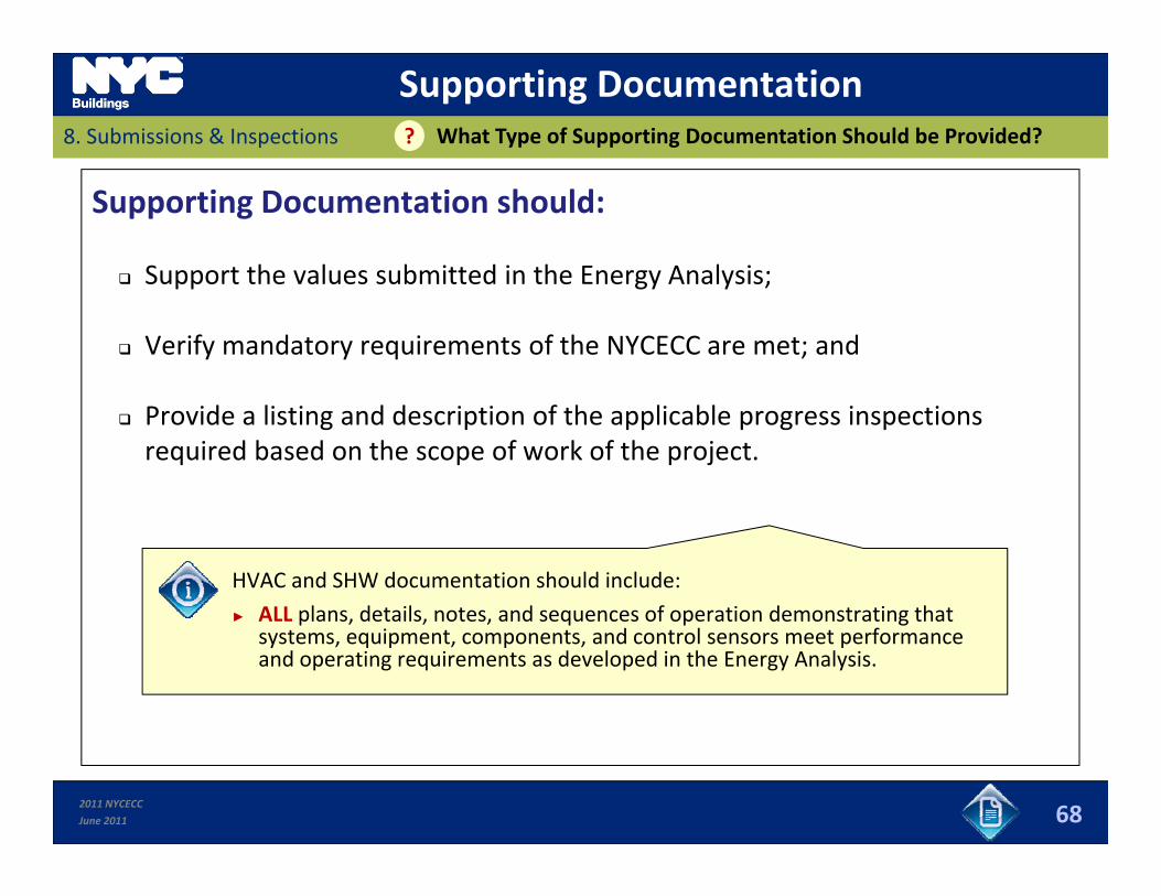
Supporting Documentation should:
Support the values submitted in the Energy Analysis; Support the values submitted in the Energy Analysis;
Verify mandatory requirements of the NYCECC are met; and
Provide a listing and description of the applicable progress inspections required based on the scope of work of the project.
HVAC and SHW documentation should include:
► ALL plans details notes and sequences of operation demonstrating that► ALL plans, details, notes, and sequences of operation demonstrating that systems, equipment, components, and control sensors meet performance and operating requirements as developed in the Energy Analysis.
2011 NYCECC
June 2011 68
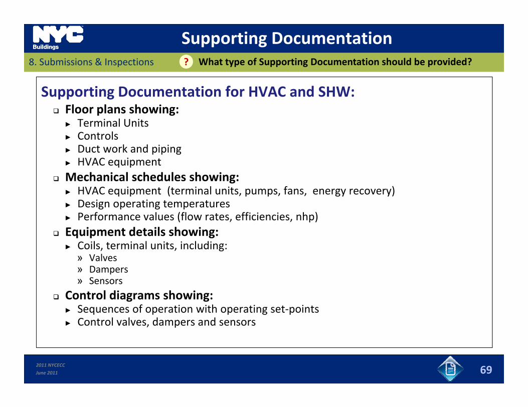
Supporting DocumentationWhat type of Supporting Documentation should be provided?8. Submissions & Inspections ?
Supporting Documentation for HVAC and SHW: Floor plans showing:
► Terminal Units► Terminal Units► Controls► Duct work and piping► HVAC equipment
Mechanical schedules showing: Mechanical schedules showing:► HVAC equipment (terminal units, pumps, fans, energy recovery)► Design operating temperatures► Performance values (flow rates, efficiencies, nhp)E i t d t il h i Equipment details showing:► Coils, terminal units, including: » Valves » Dampers» Sensors» Sensors
Control diagrams showing:► Sequences of operation with operating set‐points► Control valves, dampers and sensors
2011 NYCECC
June 2011 69
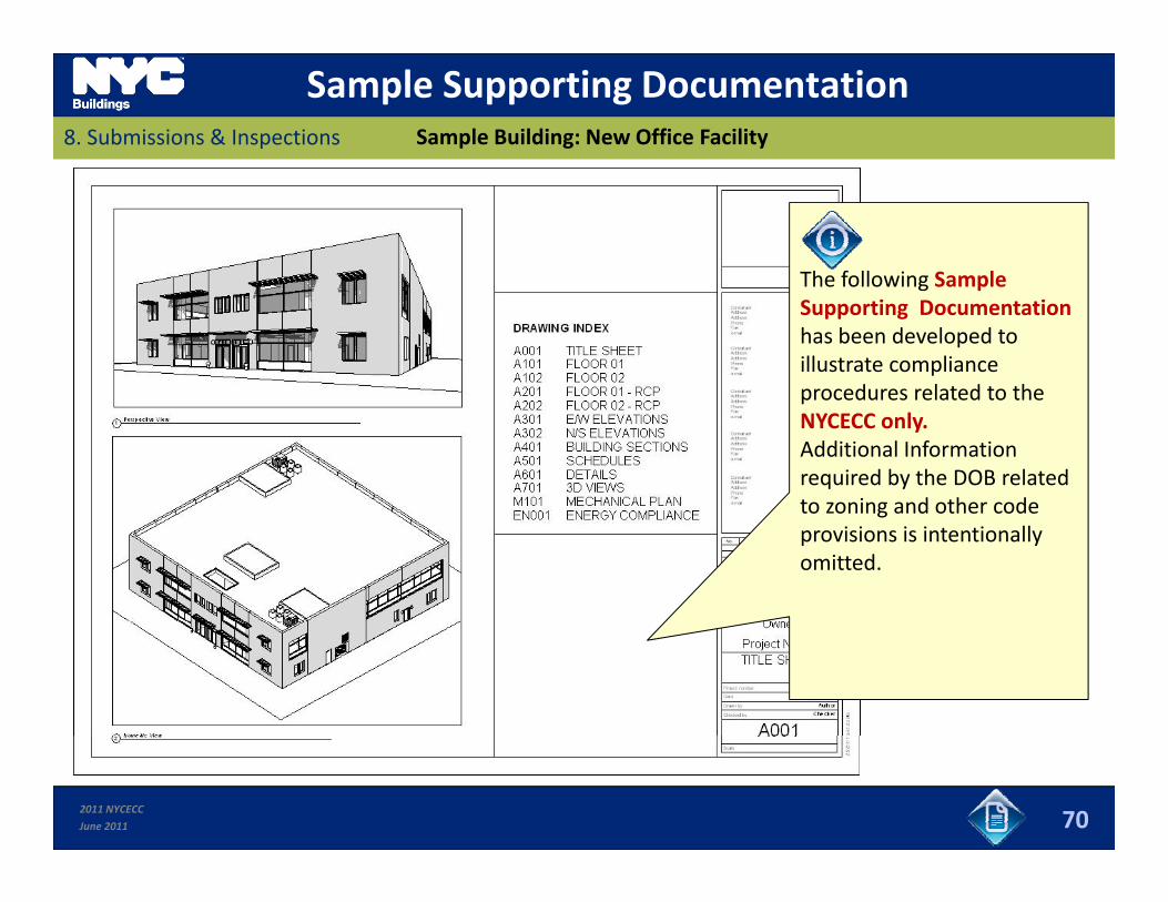
Sample Supporting Documentation8. Submissions & Inspections Sample Building: New Office Facility
The following SampleThe following Sample Supporting Documentation has been developed to illustrate compliance procedures related to theprocedures related to the NYCECC only. Additional Information required by the DOB related to zoning and other codeto zoning and other code provisions is intentionally omitted.
2011 NYCECC
June 2011 70
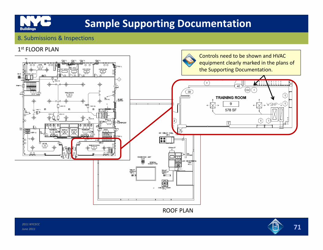
Sample Supporting Documentation8. Submissions & Inspections
1st FLOOR PLANControls need to be shown and HVAC equipment clearly marked in the plans of the Supporting Documentation.
2011 NYCECC
June 2011
ROOF PLAN
71
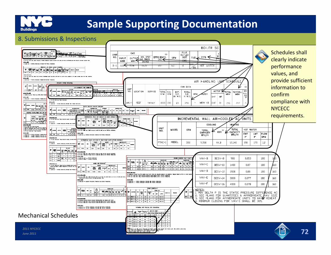
Sample Supporting Documentation8. Submissions & Inspections
Schedules shall clearly indicate performance values, and
id ffi i tprovide sufficient information to confirm compliance with NYCECC requirements.
2011 NYCECC
June 2011 72
Mechanical Schedules
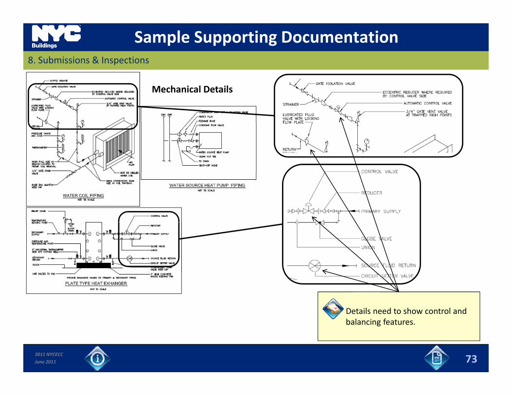
Sample Supporting Documentation8. Submissions & Inspections
Mechanical Details
Details need to show control and balancing features
2011 NYCECC
June 2011 73
balancing features.

Sample Supporting Documentation8. Submissions & Inspections
Mechanical Details
Details need to show control and balancing features
Features with different names may perform the same function with respect to code compliance. For example, a “circuit setter” and “plug valve with locking flow plate” serve
2011 NYCECC
June 2011 73
balancing features.valve with locking flow plate serve the purpose of both balancing valves.
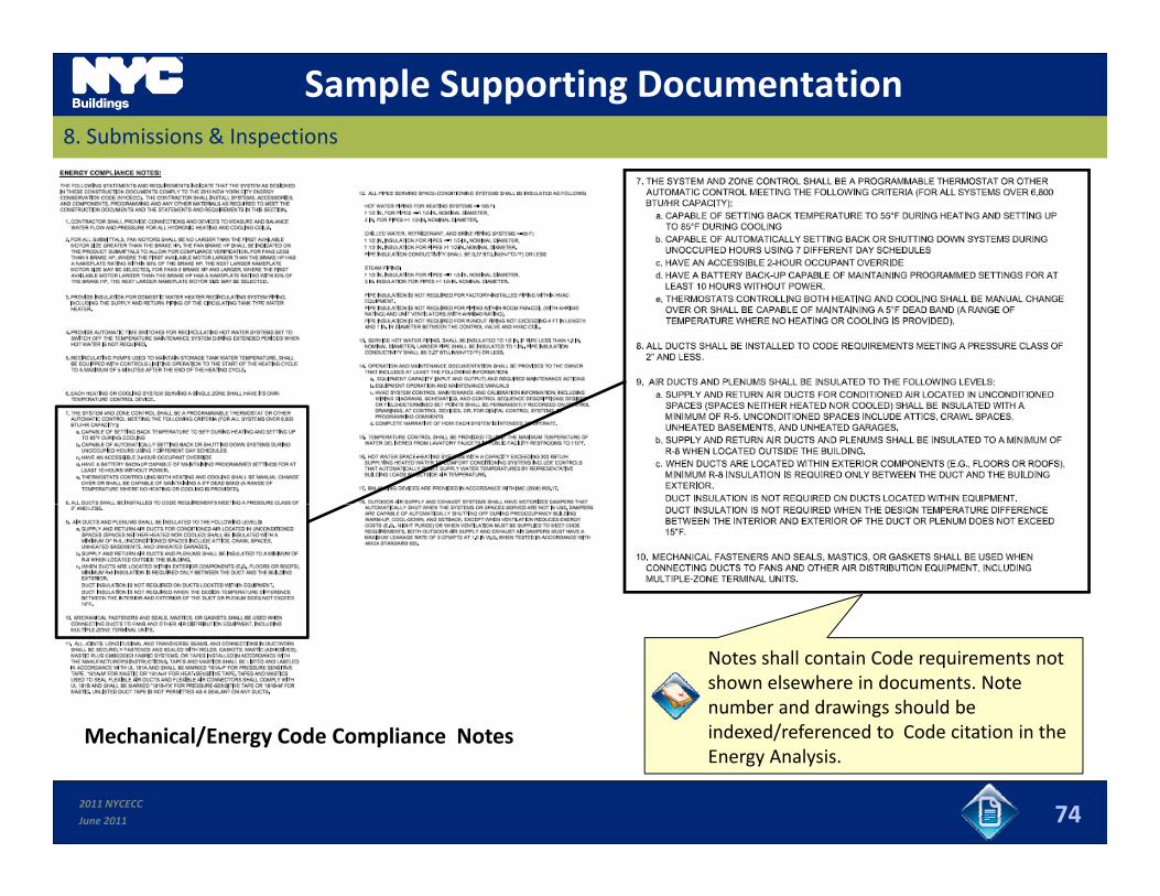
Sample Supporting Documentation8. Submissions & Inspections
Notes shall contain Code requirements not shown elsewhere in documents. Note number and drawings should be indexed/referenced to Code citation in theM h i l/E C d C li N t
2011 NYCECC
June 2011 74
indexed/referenced to Code citation in the Energy Analysis.
Mechanical/Energy Code Compliance Notes
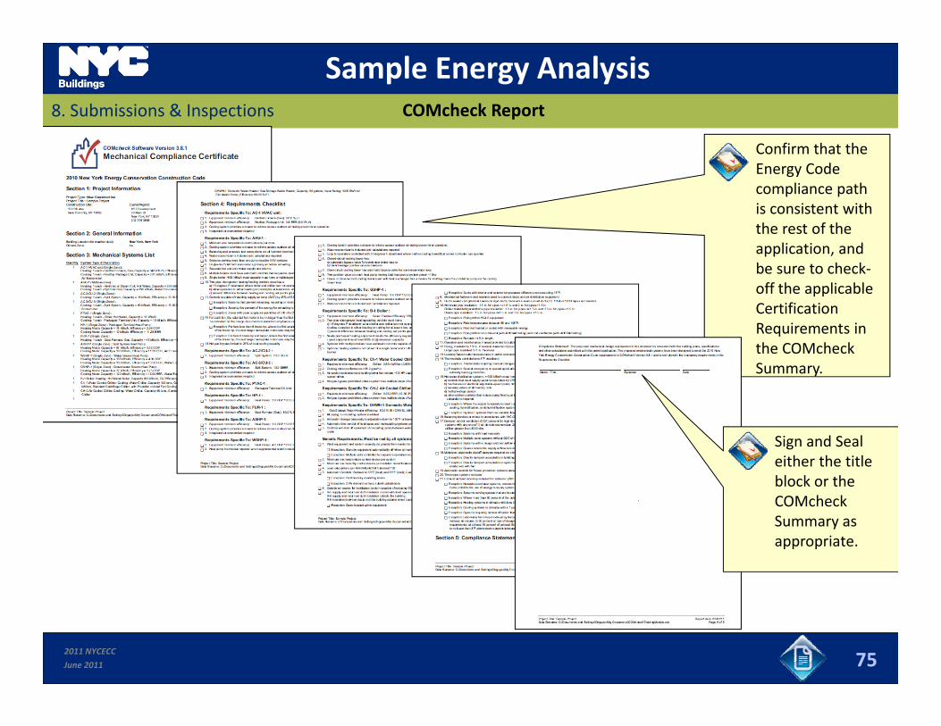
Sample Energy Analysis8. Submissions & Inspections COMcheck Report
Confirm that the Energy Code compliance path is consistent with th t f ththe rest of the application, and be sure to check‐off the applicable Certification Requirements in the COMcheck Summary.
Sign and Seal either the title block or the COMcheckCOMcheck Summary as appropriate.
2011 NYCECC
June 2011 75
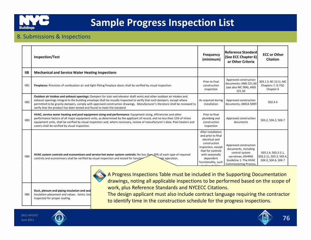
Sample Progress Inspection List8. Submissions & Inspections
Inspection/Test Frequency(minimum)
Reference Standard (See ECC Chapter 6) or Other Criteria
ECC or Other Citation
IIB Mechanical and Service Water Heating Inspections
IIB1 Fireplaces: Provision of combustion air and tight‐fitting fireplace doors shall be verified by visual inspection. Prior to final construction inspection
Approved construction documents; ANSI Z21.60 (see also MC 904), ANSI
Z21.50
303.1.5; BC 2111; MC Chapters 7, 9; FGC
Chapter 6
IIB2
Outdoor air intakes and exhaust openings: Dampers for stair and elevator shaft vents and other outdoor air intakes and exhaust openings integral to the building envelope shall be visually inspected to verify that such dampers, except where permitted to be gravity dampers, comply with approved construction drawings. Manufacturer’s literature shall be reviewed to
As required during installation
Approved construction documents; AMCA 500D
502.4.4permitted to be gravity dampers, comply with approved construction drawings. Manufacturer s literature shall be reviewed toverify that the product has been tested and found to meet the standard.
installation documents; AMCA 500
IIB3
HVAC, service water heating and pool equipment sizing and performance: Equipment sizing, efficiencies and other performance factors of all major equipment units, as determined by the applicant of record, and no less than 15% of minor equipment units, shall be verified by visual inspection and, where necessary, review of manufacturer’s data. Pool heaters andcovers shall be verified by visual inspection.
Prior to final plumbing and construction inspection
Approved construction documents
503.2, 504.2, 504.7
After installation and prior to final
IIB4HVAC system controls and economizers and service hot water system controls: No less than 20% of each type of required controls and economizers shall be verified by visual inspection and tested for functionality and proper operation.
and prior to final electrical and construction
inspection, except that for controls with seasonally dependent
functionality, such testing shall be
Approved construction documents, including
control system narratives; ASHRAE
Guideline 1: The HVAC Commissioning Process,
503.2.4, 503.2.5.1, 503.2.11, 503.3, 503.4, 504.3, 504.6, 504.7
testing shall be performed before sign‐off for issuance of a Final Certificate
of Occupancy
where applicable
IIB5Duct, plenum and piping insulation and sealing: Installed duct and piping insulation shall be visually inspected to verify proper insulation placement and values. Joints, longitudinal and transverse seams and connections in ductwork shall be visually
After installation and prior to closing h ft ili d
Approved construction documents; SMACNA Duct Construction
St d d M t l d503.2.7, 503.2.8, 504.5;
A Progress Inspections Table must be included in the Supporting Documentation drawings, noting all applicable inspections to be performed based on the scope of work, plus Reference Standards and NYCECC Citations.The design applicant must also include contract language requiring the contractor
2011 NYCECC
June 2011
p , g yinspected for proper sealing.
shafts, ceilings and walls
Standards, Metal and Flexible[; UL 181A or UL
181B]
76
The design applicant must also include contract language requiring the contractor to identify time in the construction schedule for the progress inspections.
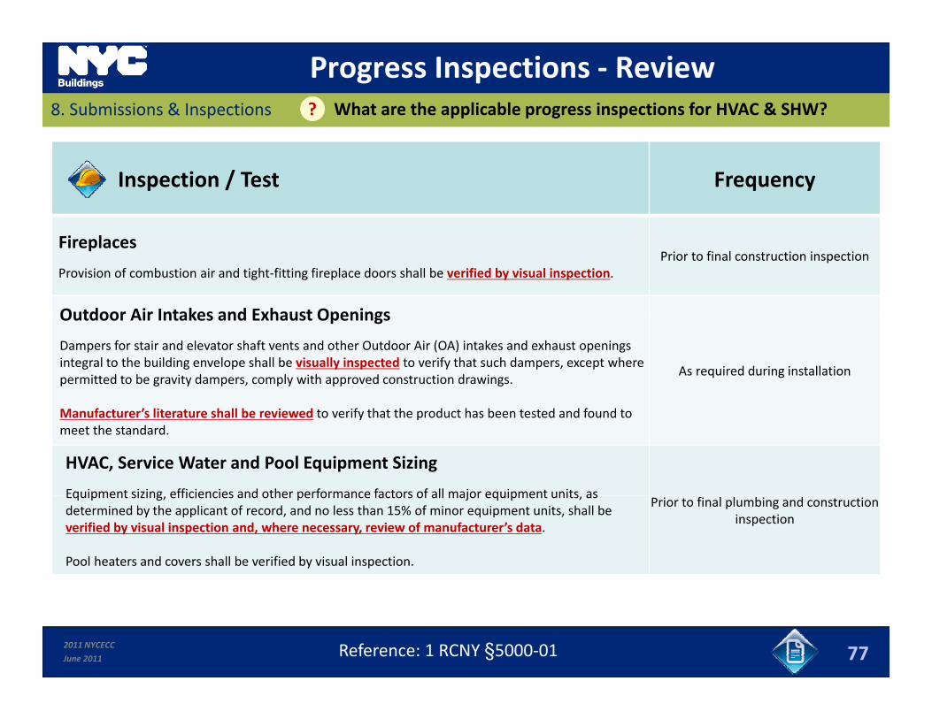
Progress Inspections ‐ ReviewWhat are the applicable progress inspections for HVAC & SHW?8. Submissions & Inspections ?
Inspection / Test Frequency
Fireplaces
Provision of combustion air and tight‐fitting fireplace doors shall be verified by visual inspection.Prior to final construction inspection
Outdoor Air Intakes and Exhaust OpeningsOutdoor Air Intakes and Exhaust Openings
Dampers for stair and elevator shaft vents and other Outdoor Air (OA) intakes and exhaust openings integral to the building envelope shall be visually inspected to verify that such dampers, except where permitted to be gravity dampers, comply with approved construction drawings.
As required during installation
Manufacturer’s literature shall be reviewed to verify that the product has been tested and found to meet the standard.
HVAC, Service Water and Pool Equipment Sizing
Equipment sizing efficiencies and other performance factors of all major equipment units asEquipment sizing, efficiencies and other performance factors of all major equipment units, as determined by the applicant of record, and no less than 15% of minor equipment units, shall be verified by visual inspection and, where necessary, review of manufacturer’s data.
Pool heaters and covers shall be verified by visual inspection.
Prior to final plumbing and construction inspection
2011 NYCECC
June 2011 77Reference: 1 RCNY §5000‐01
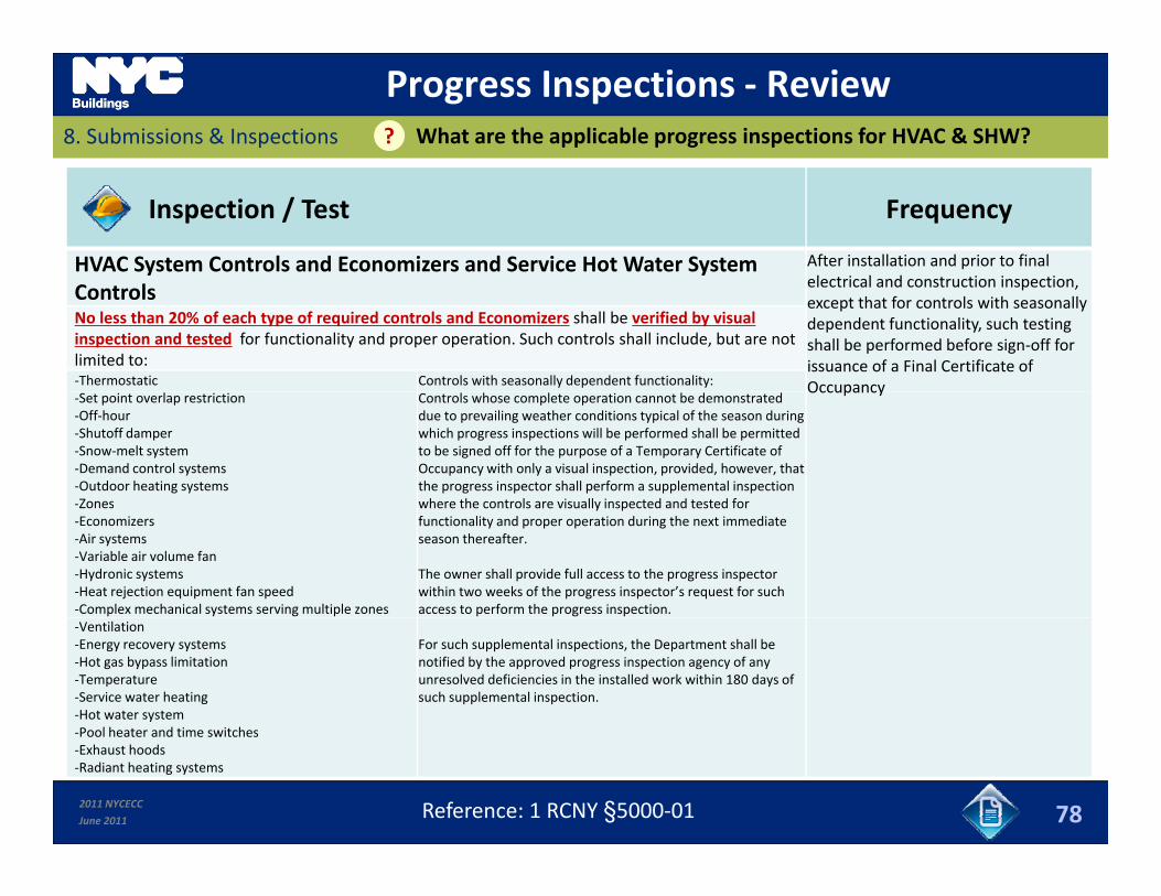
Progress Inspections ‐ ReviewWhat are the applicable progress inspections for HVAC & SHW?8. Submissions & Inspections ?
Inspection / Test Frequency
HVAC System Controls and Economizers and Service Hot Water System After installation and prior to final l t i l d t ti i tiControls electrical and construction inspection, except that for controls with seasonally dependent functionality, such testing shall be performed before sign‐off for issuance of a Final Certificate of Occupancy
No less than 20% of each type of required controls and Economizers shall be verified by visual inspection and tested for functionality and proper operation. Such controls shall include, but are not limited to:‐Thermostatic Controls with seasonally dependent functionality: Occupancy‐Set point overlap restriction‐Off‐hour‐Shutoff damper‐Snow‐melt system‐Demand control systems‐Outdoor heating systems‐Zones
Controls whose complete operation cannot be demonstrated due to prevailing weather conditions typical of the season during which progress inspections will be performed shall be permitted to be signed off for the purpose of a Temporary Certificate of Occupancy with only a visual inspection, provided, however, that the progress inspector shall perform a supplemental inspection where the controls are visually inspected and tested for‐Zones
‐Economizers‐Air systems‐Variable air volume fan‐Hydronic systems‐Heat rejection equipment fan speed‐Complex mechanical systems serving multiple zones
where the controls are visually inspected and tested for functionality and proper operation during the next immediate season thereafter.
The owner shall provide full access to the progress inspector within two weeks of the progress inspector’s request for such access to perform the progress inspection.
‐Ventilation‐Energy recovery systems‐Hot gas bypass limitation‐Temperature‐Service water heating‐Hot water systemPool heater and time switches
For such supplemental inspections, the Department shall be notified by the approved progress inspection agency of any unresolved deficiencies in the installed work within 180 days of such supplemental inspection.
2011 NYCECC
June 2011
‐Pool heater and time switches‐Exhaust hoods‐Radiant heating systems
78Reference: 1 RCNY §5000‐01
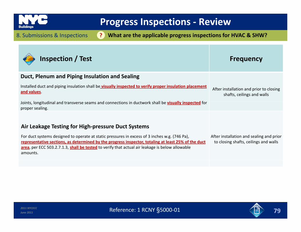
Progress Inspections ‐ ReviewWhat are the applicable progress inspections for HVAC & SHW?8. Submissions & Inspections ?
Inspection / Test Frequency
Duct, Plenum and Piping Insulation and Sealing
Installed duct and piping insulation shall be visually inspected to verify proper insulation placement and values.
J i l i di l d d i i d k h ll b i ll i t d f
After installation and prior to closing shafts, ceilings and walls
Joints, longitudinal and transverse seams and connections in ductwork shall be visually inspected for proper sealing.
Air Leakage Testing for High‐pressure Duct Systems
For duct systems designed to operate at static pressures in excess of 3 inches w.g. (746 Pa), representative sections, as determined by the progress inspector, totaling at least 25% of the duct area, per ECC 503.2.7.1.3, shall be tested to verify that actual air leakage is below allowable amounts.
After installation and sealing and prior to closing shafts, ceilings and walls
2011 NYCECC
June 2011 79Reference: 1 RCNY §5000‐01
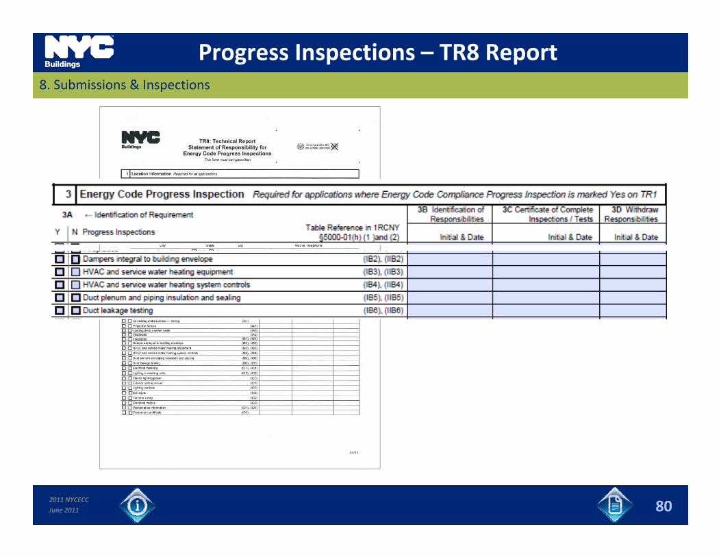
Progress Inspections – TR8 Report8. Submissions & Inspections
2011 NYCECC
June 2011 80
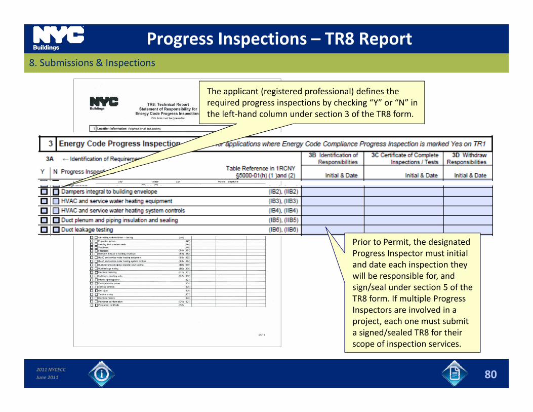
Progress Inspections – TR8 Report8. Submissions & Inspections
The applicant (registered professional) defines the required progress inspections by checking “Y” or “N” in the left‐hand column under section 3 of the TR8 form.
Prior to Permit, the designated Progress Inspector must initial and date each inspection they will be responsible for, and i / l d i f hsign/seal under section 5 of the TR8 form. If multiple Progress Inspectors are involved in a project, each one must submit a signed/sealed TR8 for their
2011 NYCECC
June 2011
g /scope of inspection services.
80
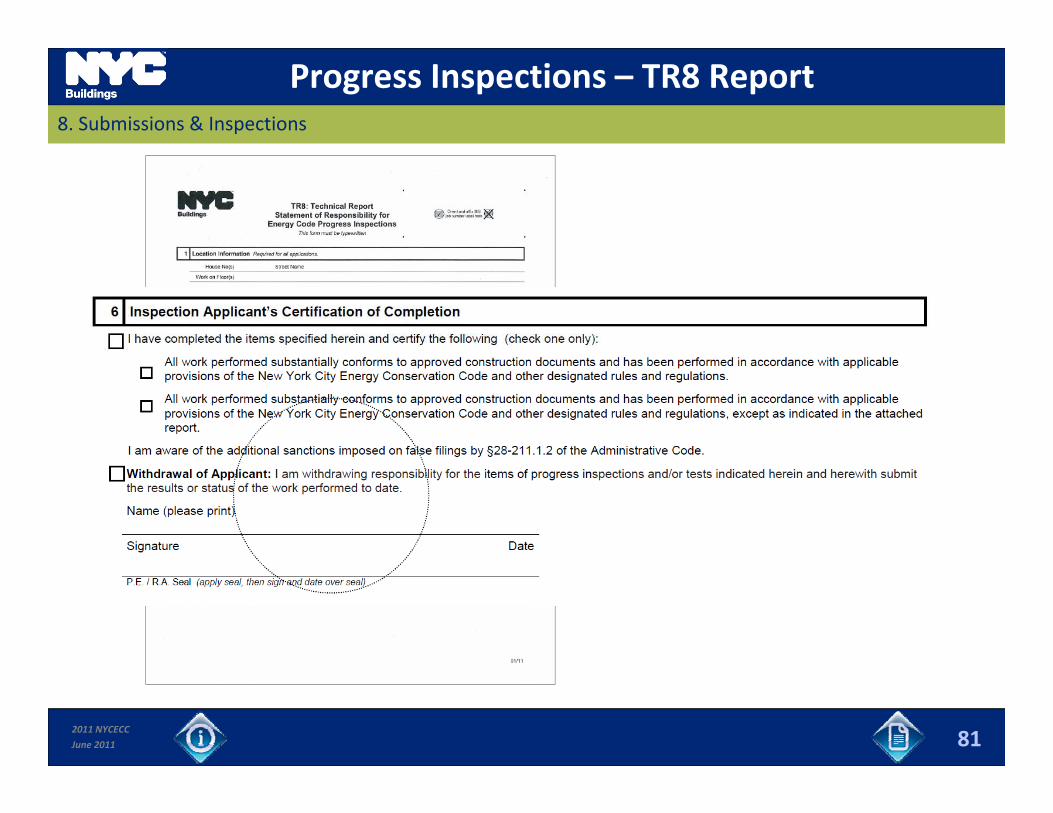
Progress Inspections – TR8 Report8. Submissions & Inspections
2011 NYCECC
June 2011 81
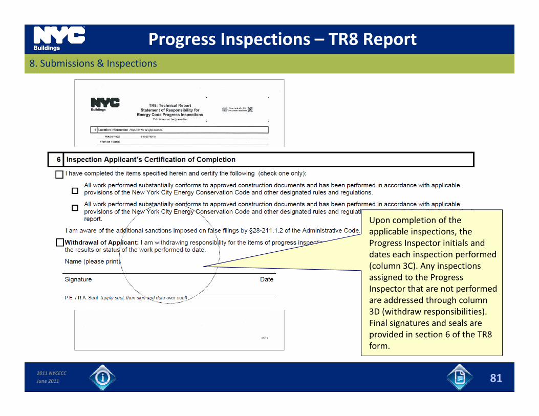
Progress Inspections – TR8 Report8. Submissions & Inspections
Upon completion of the applicable inspections, theapplicable inspections, the Progress Inspector initials and dates each inspection performed (column 3C). Any inspections assigned to the Progress I t th t t f dInspector that are not performed are addressed through column 3D (withdraw responsibilities). Final signatures and seals are provided in section 6 of the TR8
2011 NYCECC
June 2011
form.
81
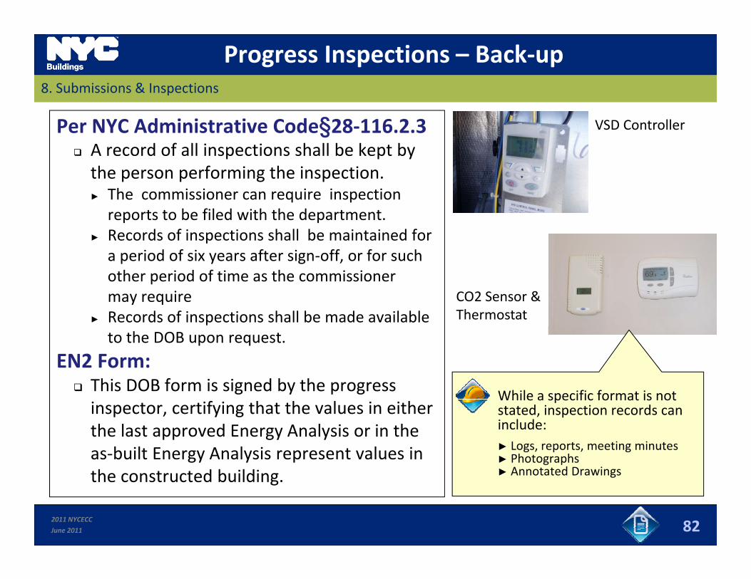
Progress Inspections – Back‐up8. Submissions & Inspections
Per NYC Administrative Code§28‐116.2.3 A record of all inspections shall be kept by the person performing the inspection.
VSD Controller
p p g p► The commissioner can require inspection reports to be filed with the department.
► Records of inspections shall be maintained for a period of six years after sign off or for sucha period of six years after sign‐off, or for such other period of time as the commissioner may require
► Records of inspections shall be made available CO2 Sensor &Thermostat
to the DOB upon request.
EN2 Form: This DOB form is signed by the progress
While a specific format is notinspector, certifying that the values in either the last approved Energy Analysis or in the as‐built Energy Analysis represent values in th t t d b ildi
While a specific format is not stated, inspection records can include:► Logs, reports, meeting minutes► Photographs► Annotated Drawings
2011 NYCECC
June 2011
the constructed building. ► Annotated Drawings
82

Progress Inspections – EN2 Form8. Submissions & Inspections
2011 NYCECC
June 2011 83
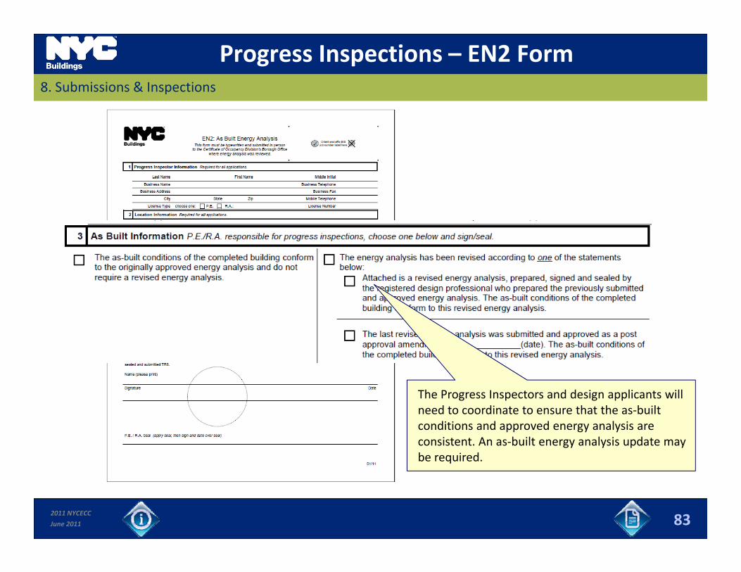
Progress Inspections – EN2 Form8. Submissions & Inspections
The Progress Inspectors and design applicants willThe Progress Inspectors and design applicants will need to coordinate to ensure that the as‐built conditions and approved energy analysis are consistent. An as‐built energy analysis update may be required.
2011 NYCECC
June 2011 83
Slides 84 to 88 9. ResourcesHVAC ‐ 2
2011 NYCECC
June 2011 84
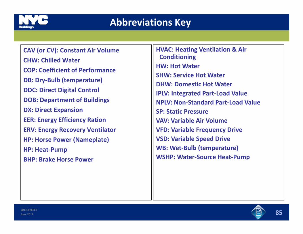
Abbreviations Key
CAV (or CV): Constant Air Volume
CHW: Chilled Water
COP: Coefficient of Performance
HVAC: Heating Ventilation & Air ConditioningHW: Hot Water
iDB: Dry‐Bulb (temperature)
DDC: Direct Digital Control
DOB: Department of Buildings
SHW: Service Hot WaterDHW: Domestic Hot WaterIPLV: Integrated Part‐Load ValueNPLV: Non Standard Part Load Valuep g
DX: Direct Expansion
EER: Energy Efficiency Ration
ERV: Energy Recovery Ventilator
NPLV: Non‐Standard Part‐Load ValueSP: Static PressureVAV: Variable Air VolumeVFD: Variable Frequency Drive: e gy eco e y e t ato
HP: Horse Power (Nameplate)
HP: Heat‐Pump
BHP: Brake Horse Power
: a ab e eque cy eVSD: Variable Speed DriveWB: Wet‐Bulb (temperature)WSHP: Water‐Source Heat‐PumpBHP: Brake Horse Power
2011 NYCECC
June 2011 85
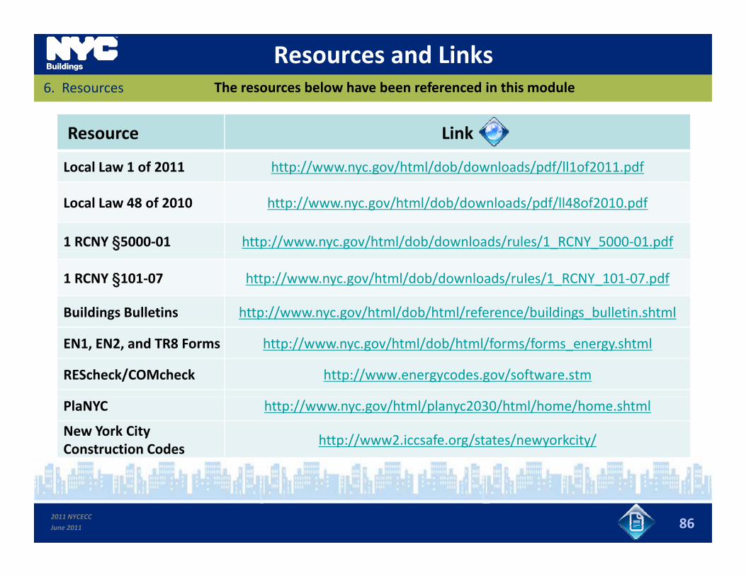
Resources and LinksThe resources below have been referenced in this module6. Resources
Resource Link
Local Law 1 of 2011 http://www.nyc.gov/html/dob/downloads/pdf/ll1of2011.pdf
Local Law 48 of 2010 http://www.nyc.gov/html/dob/downloads/pdf/ll48of2010.pdf
1 RCNY §5000‐01 http://www.nyc.gov/html/dob/downloads/rules/1_RCNY_5000‐01.pdf
1 RCNY §101‐07 http://www.nyc.gov/html/dob/downloads/rules/1_RCNY_101‐07.pdf
Buildings Bulletins http://www.nyc.gov/html/dob/html/reference/buildings_bulletin.shtml
EN1, EN2, and TR8 Forms http://www.nyc.gov/html/dob/html/forms/forms_energy.shtml
REScheck/COMcheck http://www.energycodes.gov/software.stm
PlaNYC http://www.nyc.gov/html/planyc2030/html/home/home.shtml
New York City Construction Codes
http://www2.iccsafe.org/states/newyorkcity/
2011 NYCECC
June 2011 86
DOB Assistance9. Resources
Questions on the NYCECC can be submitted to the DOB at:
2011 NYCECC
June 2011 87

12. Resources
Image / Photo Credits & Copyrights
Company or Individual Slide Numbers
Samantha Modell 84
www.energysavers.gov 53
2011 NYCECC
June 2011 88