ASME B16.5 API ICP
287
互动员: Charlie Chong/ Fion Zhang/ He Jungang / Li Xueliang Pipe Flanges and Flanged Fittings NPS 1/2 Through NPS 24 Metric/Inch Standard ASME B16.5 “管法兰” 和 “法兰管件” JCCCSH 2013年内部培训
-
Upload
charlie-chong -
Category
Engineering
-
view
531 -
download
62
description
API 570 ICP Self study note
Transcript of ASME B16.5 API ICP
互动员:Charlie Chong/ Fion Zhang/ He Jungang / Li Xueliang
Pipe Flanges andFlanged FittingsNPS 1/2 Through NPS 24Metric/Inch StandardASME B16.5 “管法兰” 和 “法兰管件”
JCCCSH2013年内部培训

Charlie Chong/ Fion Zhang/ He Jungang / Li Xueliang
2013年5月Charlie 上海Fion Zhang 上海Jack He 上海Xueliang Li 嘉兴
571-Intro

Charlie Chong/ Fion Zhang/ He Jungang / Li XueliangASTM 16.5 -Intro
美丽的南海 – 中国固有的蓝色疆土

Charlie Chong/ Fion Zhang/ He Jungang / Li XueliangASTM 16.5 -Intro
管法兰和法兰管件 - JCCCSH 2013年内部培训

Charlie Chong/ Fion Zhang/ He Jungang / Li Xueliang
Speaker: Fion Zhang2013/5/5
ASTM 16.5 -Intro
Charlie Chong/ Fion Zhang/ He Jungang / Li XueliangASTM 16.5
CONTENTS 目录Foreword 诸言
1 Scope 范围2 Pressure–Temperature Ratings压力温度等级3 Component Size元件尺码4 Marking 标志5 Materials 材料6 Dimensions 尺寸7 Tolerances 公差8 Pressure Testing 压力测试
Mandatory Appendices 强制性附录Non-Mandatory Appendices 非强制性附录
Charlie Chong/ Fion Zhang/ He Jungang / Li XueliangASTM 16.5 -foreword
Foreword 诸言讲述了这规范的来龙去脉.

Charlie Chong/ Fion Zhang/ He Jungang / Li XueliangASTM 16.5 -1
1 SCOPE范围
Charlie Chong/ Fion Zhang/ He Jungang / Li Xueliang
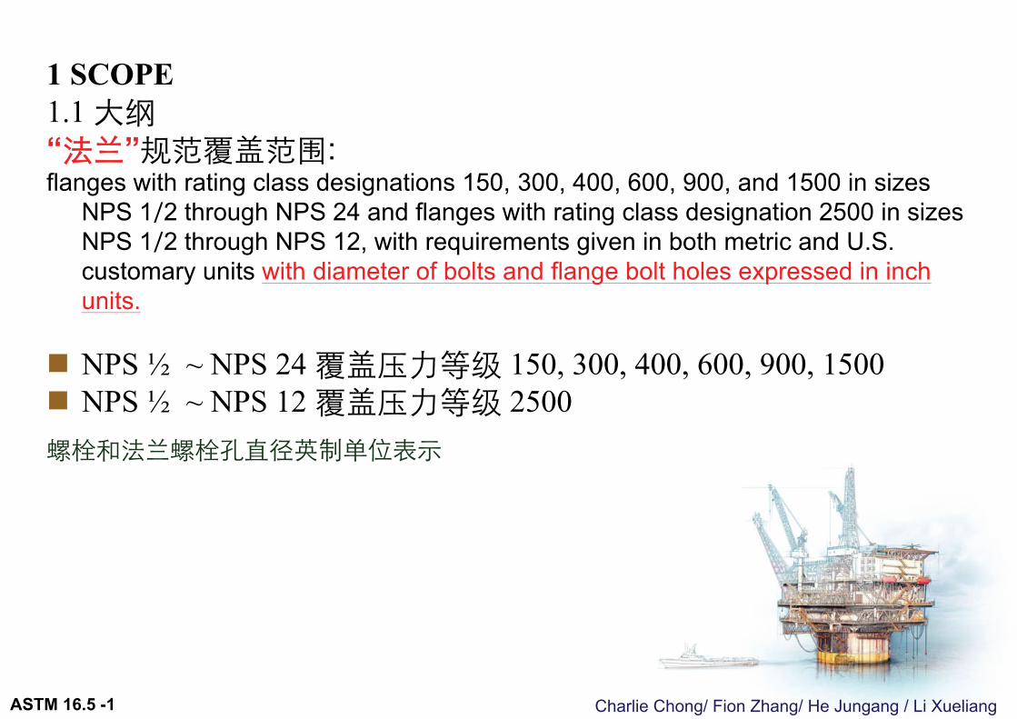
1 SCOPE1.1 大纲“法兰”规范覆盖范围:flanges with rating class designations 150, 300, 400, 600, 900, and 1500 in sizes
NPS 1⁄2 through NPS 24 and flanges with rating class designation 2500 in sizes NPS 1⁄2 through NPS 12, with requirements given in both metric and U.S. customary units with diameter of bolts and flange bolt holes expressed in inch units.
NPS ½ ~ NPS 24 覆盖压力等级 150, 300, 400, 600, 900, 1500 NPS ½ ~ NPS 12 覆盖压力等级 2500螺栓和法兰螺栓孔直径英制单位表示
ASTM 16.5 -1
Charlie Chong/ Fion Zhang/ He Jungang / Li Xueliang
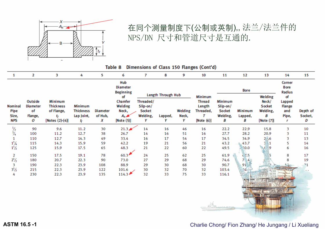
在同个测量制度下(公制或英制),, 法兰/法兰件的
NPS/DN 尺寸和管道尺寸是互通的.
ASTM 16.5 -1
Charlie Chong/ Fion Zhang/ He Jungang / Li Xueliang
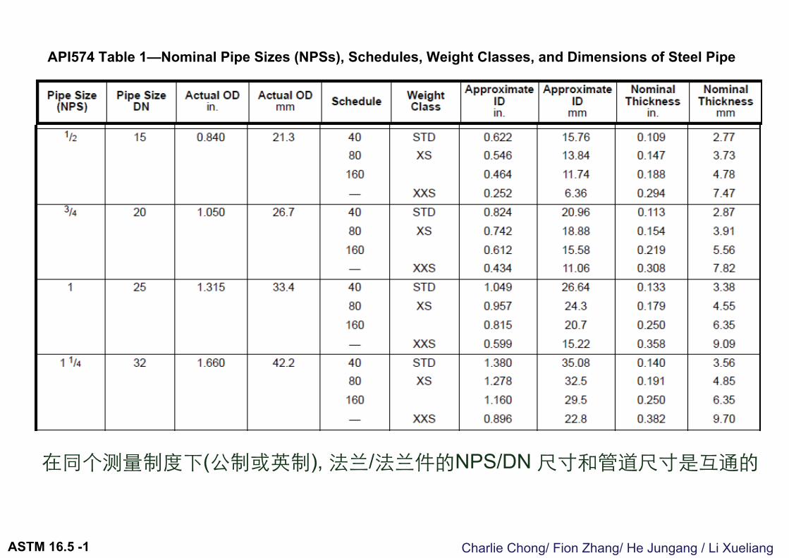
在同个测量制度下(公制或英制), 法兰/法兰件的NPS/DN 尺寸和管道尺寸是互通的
API574 Table 1—Nominal Pipe Sizes (NPSs), Schedules, Weight Classes, and Dimensions of Steel Pipe
ASTM 16.5 -1
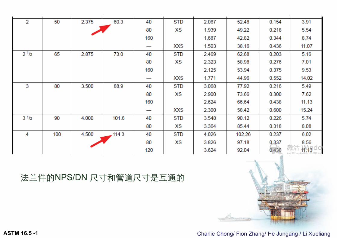
Charlie Chong/ Fion Zhang/ He Jungang / Li Xueliang
法兰件的NPS/DN 尺寸和管道尺寸是互通的
ASTM 16.5 -1
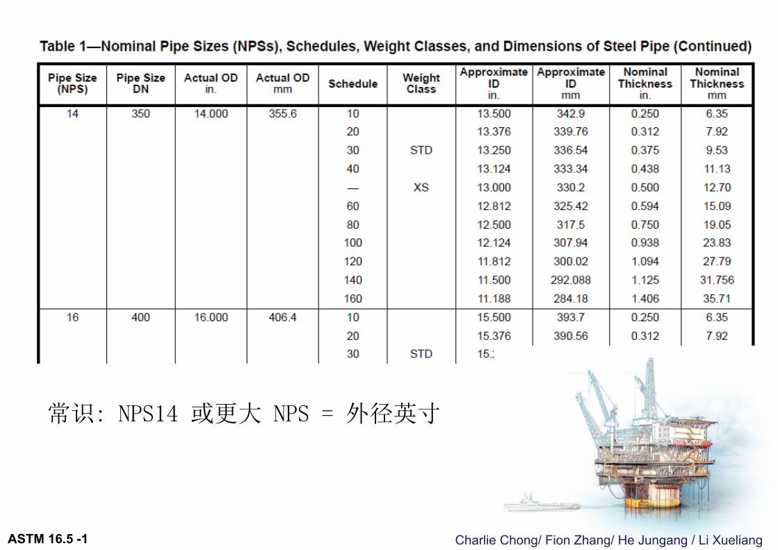
常识: NPS14 或更大 NPS = 外径英寸
Charlie Chong/ Fion Zhang/ He Jungang / Li XueliangASTM 16.5 -1
Charlie Chong/ Fion Zhang/ He Jungang / Li Xueliang
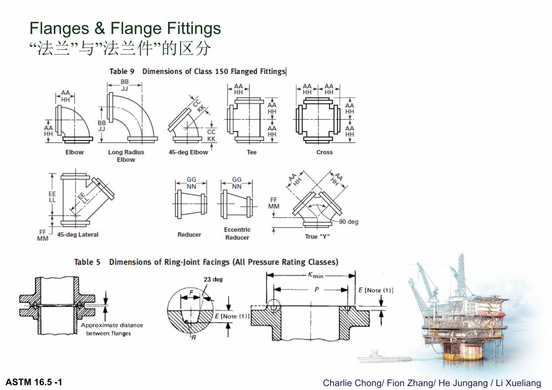
Flanges & Flange Fittings “法兰”与”法兰件”的区分
ASTM 16.5 -1
Charlie Chong/ Fion Zhang/ He Jungang / Li Xueliang
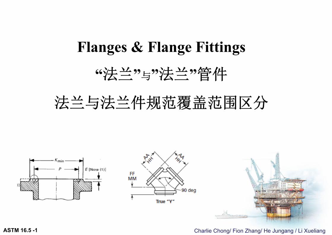
Flanges & Flange Fittings
“法兰”与”法兰”管件
法兰与法兰件规范覆盖范围区分
ASTM 16.5 -1
Charlie Chong/ Fion Zhang/ He Jungang / Li Xueliang
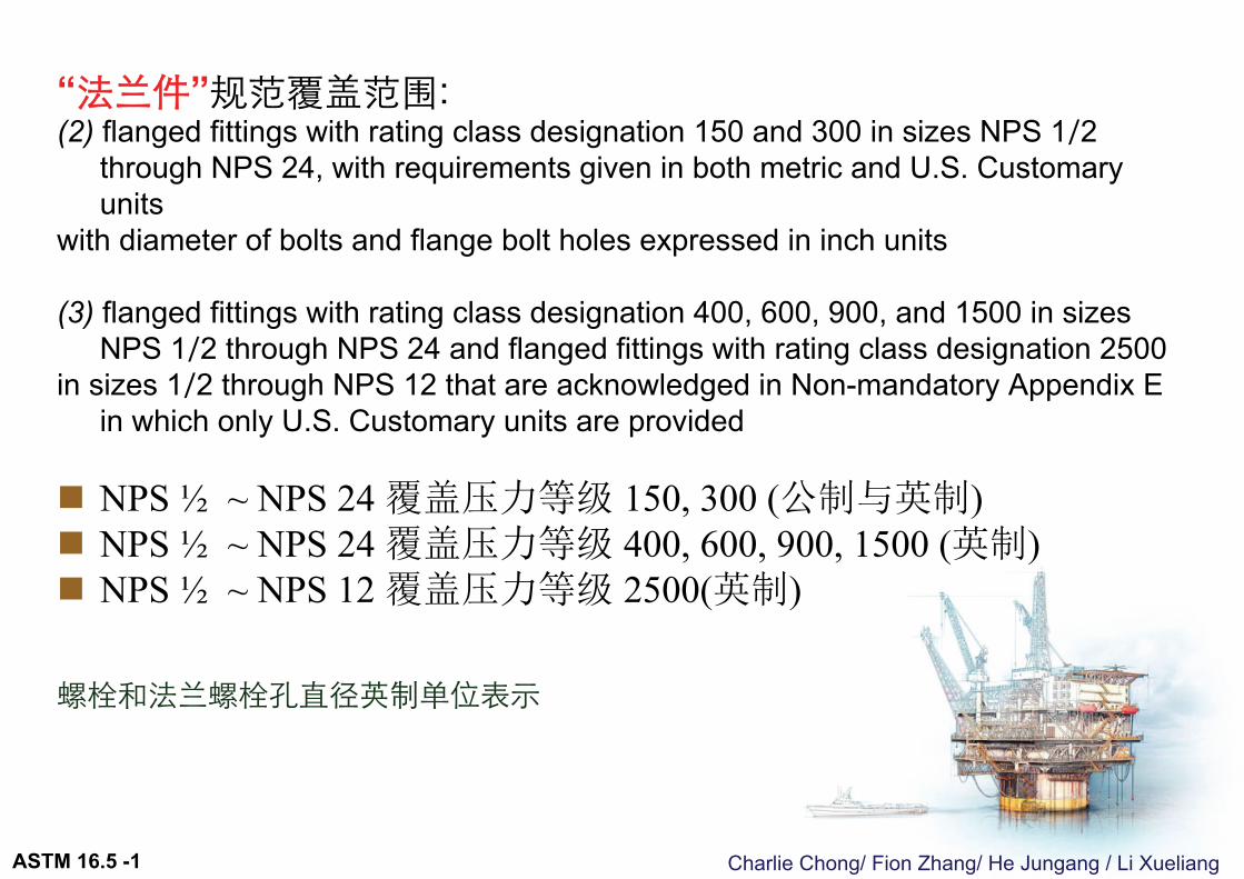
“法兰件”规范覆盖范围:(2) flanged fittings with rating class designation 150 and 300 in sizes NPS 1⁄2
through NPS 24, with requirements given in both metric and U.S. Customary units
with diameter of bolts and flange bolt holes expressed in inch units
(3) flanged fittings with rating class designation 400, 600, 900, and 1500 in sizes NPS 1⁄2 through NPS 24 and flanged fittings with rating class designation 2500
in sizes 1⁄2 through NPS 12 that are acknowledged in Non-mandatory Appendix E in which only U.S. Customary units are provided
NPS ½ ~ NPS 24 覆盖压力等级 150, 300 (公制与英制) NPS ½ ~ NPS 24 覆盖压力等级 400, 600, 900, 1500 (英制) NPS ½ ~ NPS 12 覆盖压力等级 2500(英制)
螺栓和法兰螺栓孔直径英制单位表示
ASTM 16.5 -1
Charlie Chong/ Fion Zhang/ He Jungang / Li Xueliang
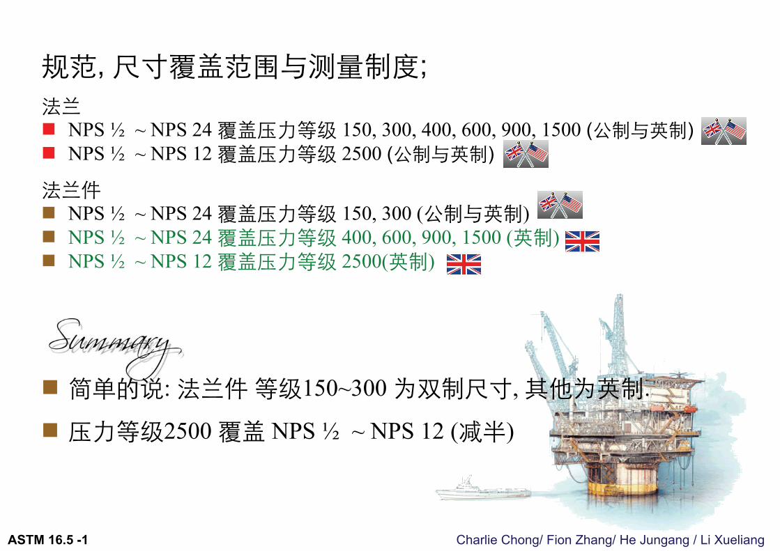
规范, 尺寸覆盖范围与测量制度;法兰 NPS ½ ~ NPS 24 覆盖压力等级 150, 300, 400, 600, 900, 1500 (公制与英制) NPS ½ ~ NPS 12 覆盖压力等级 2500 (公制与英制)
法兰件 NPS ½ ~ NPS 24 覆盖压力等级 150, 300 (公制与英制) NPS ½ ~ NPS 24 覆盖压力等级 400, 600, 900, 1500 (英制) NPS ½ ~ NPS 12 覆盖压力等级 2500(英制)
简单的说: 法兰件等级150~300 为双制尺寸, 其他为英制.
压力等级2500 覆盖 NPS ½ ~ NPS 12 (减半)
ASTM 16.5 -1
Charlie Chong/ Fion Zhang/ He Jungang / Li Xueliang
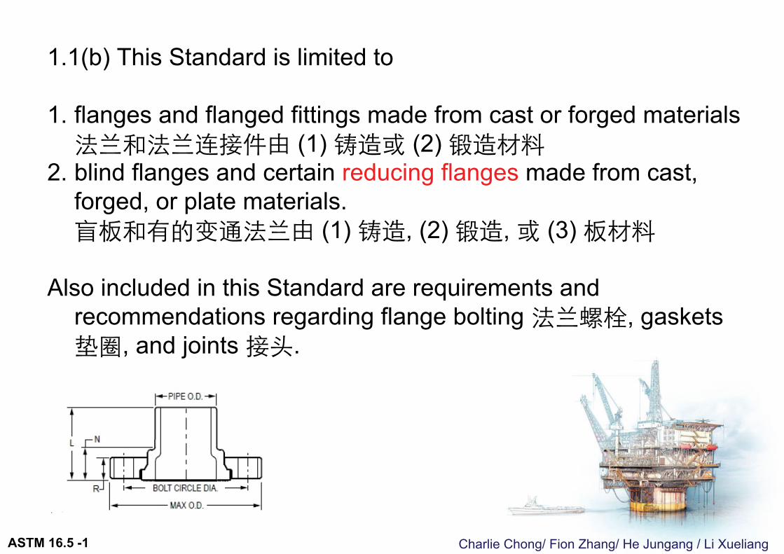
1.1(b) This Standard is limited to
1. flanges and flanged fittings made from cast or forged materials法兰和法兰连接件由 (1) 铸造或 (2) 锻造材料
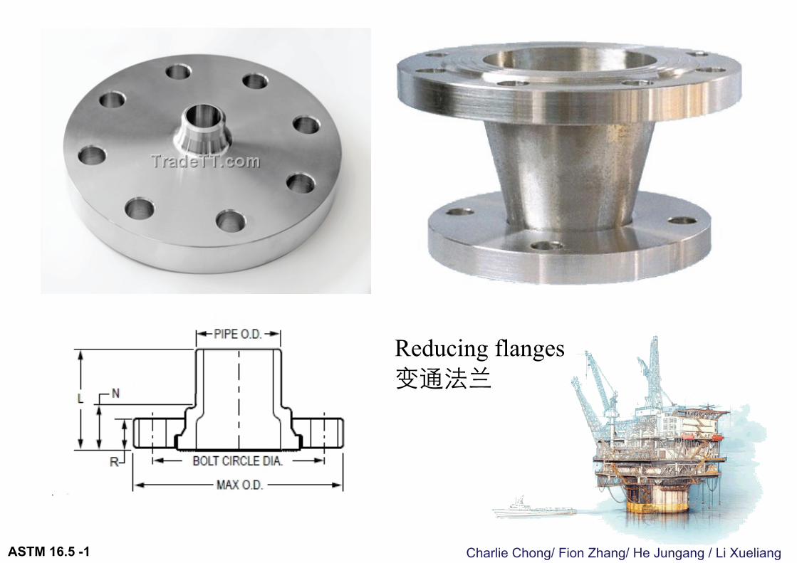
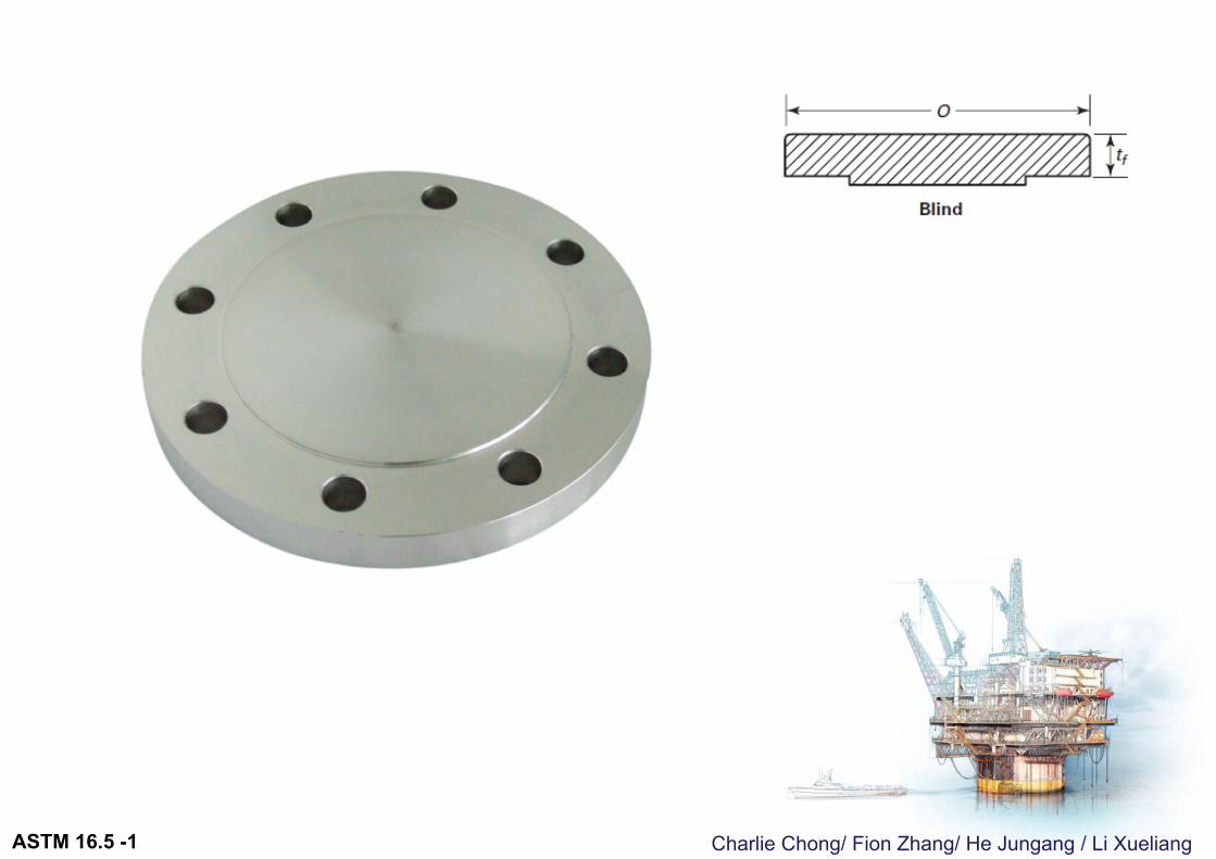
2. blind flanges and certain reducing flanges made from cast, forged, or plate materials.盲板和有的变通法兰由 (1) 铸造, (2) 锻造, 或 (3) 板材料
Also included in this Standard are requirements and recommendations regarding flange bolting 法兰螺栓, gaskets 垫圈, and joints 接头.
ASTM 16.5 -1
Charlie Chong/ Fion Zhang/ He Jungang / Li Xueliang
Reducing flanges变通法兰
ASTM 16.5 -1
Charlie Chong/ Fion Zhang/ He Jungang / Li Xueliang
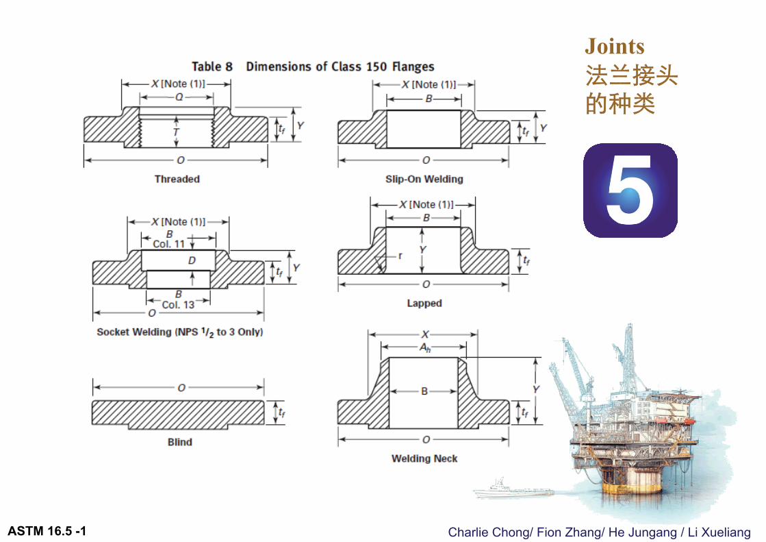
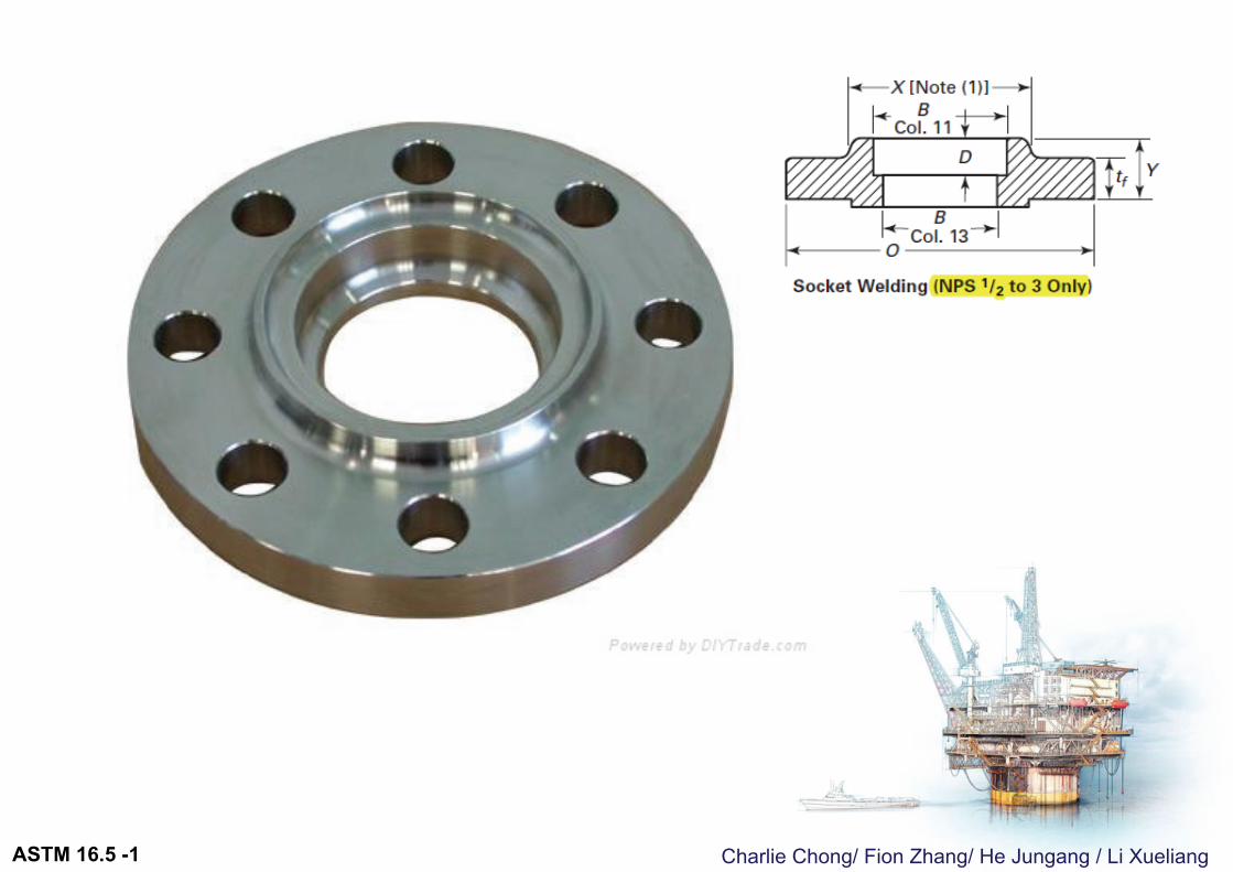
Joints 法兰接头的种类
ASTM 16.5 -1
Charlie Chong/ Fion Zhang/ He Jungang / Li Xueliang
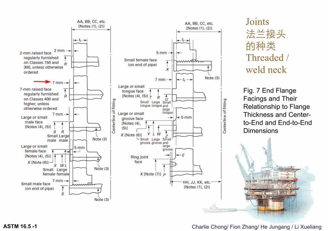
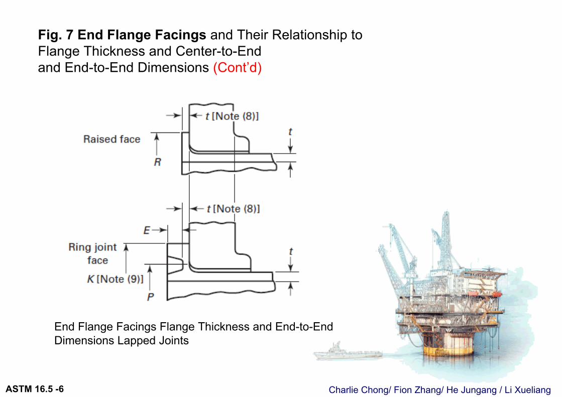
Fig. 7 End Flange Facings and Their Relationship to Flange Thickness and Center-to-End and End-to-End Dimensions
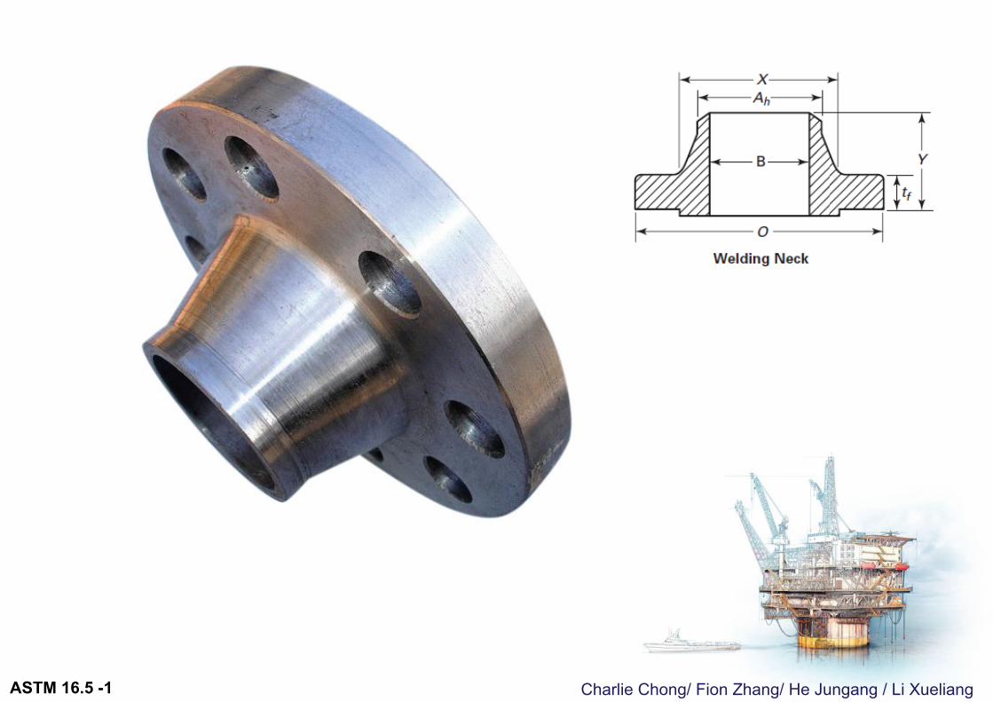
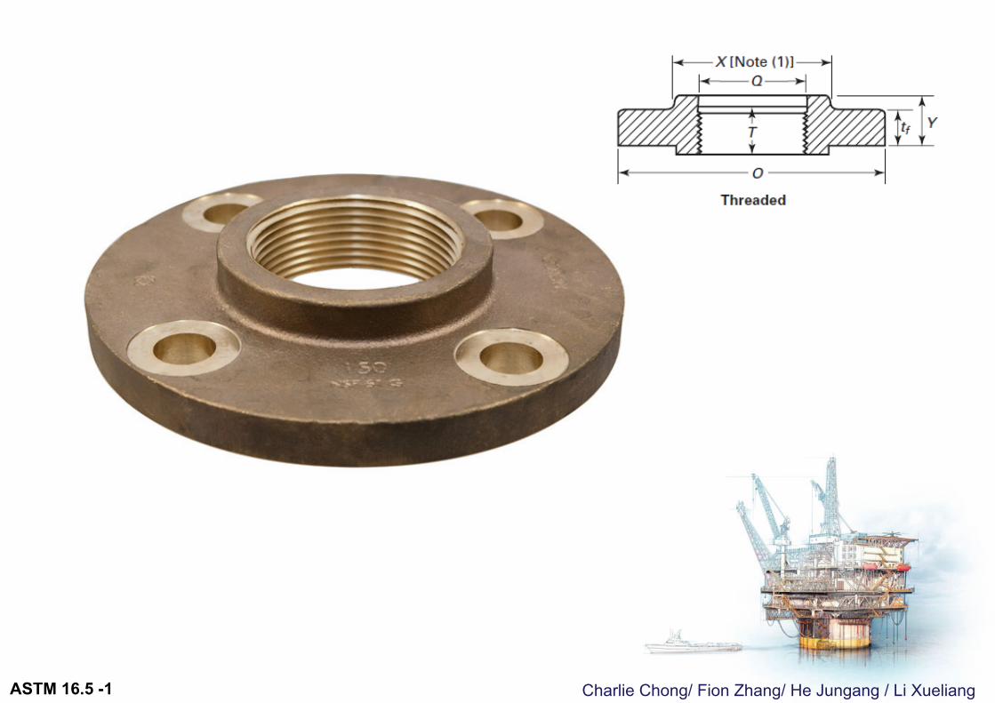
Joints 法兰接头的种类Threaded / weld neck
ASTM 16.5 -1
Charlie Chong/ Fion Zhang/ He Jungang / Li Xueliang
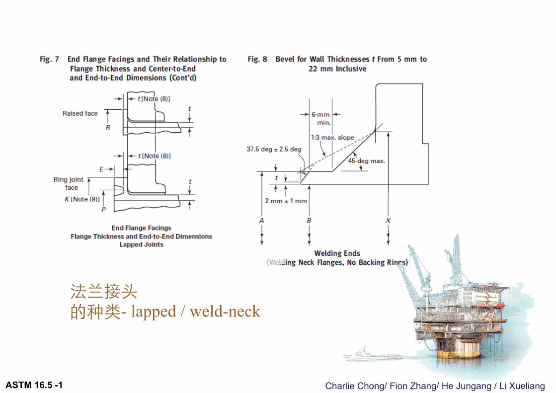
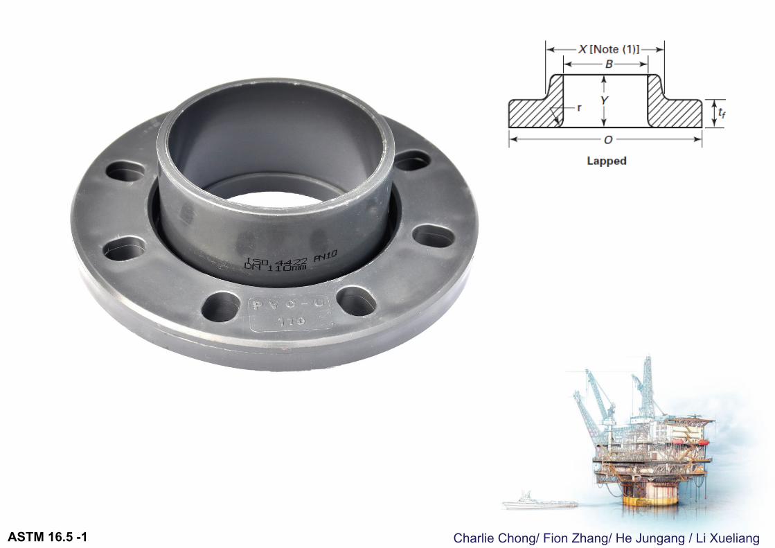
法兰接头的种类- lapped / weld-neck
ASTM 16.5 -1
Charlie Chong/ Fion Zhang/ He Jungang / Li XueliangASTM 16.5 -1
Charlie Chong/ Fion Zhang/ He Jungang / Li XueliangASTM 16.5 -1
Charlie Chong/ Fion Zhang/ He Jungang / Li XueliangASTM 16.5 -1
Charlie Chong/ Fion Zhang/ He Jungang / Li XueliangASTM 16.5 -1
Charlie Chong/ Fion Zhang/ He Jungang / Li XueliangASTM 16.5 -1
Charlie Chong/ Fion Zhang/ He Jungang / Li XueliangASTM 16.5 -1
Charlie Chong/ Fion Zhang/ He Jungang / Li Xueliang
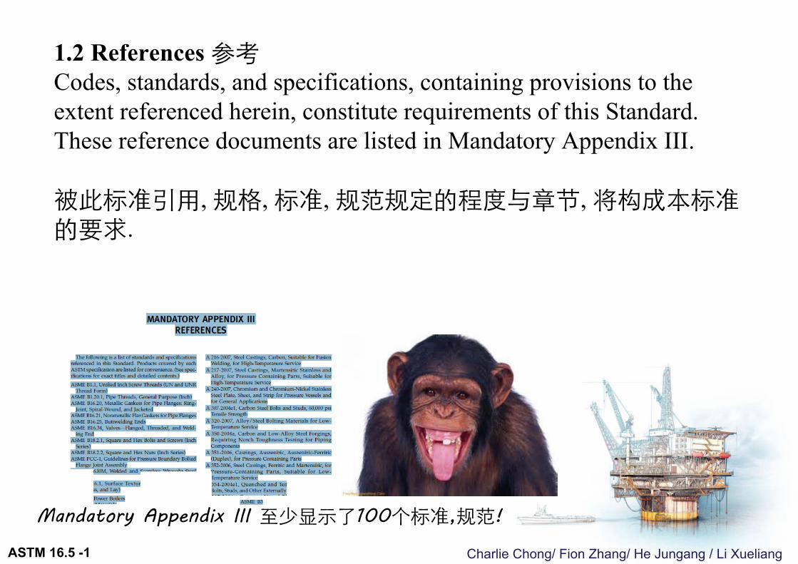
1.2 References 参考Codes, standards, and specifications, containing provisions to the extent referenced herein, constitute requirements of this Standard. These reference documents are listed in Mandatory Appendix III.
被此标准引用, 规格, 标准, 规范规定的程度与章节, 将构成本标准的要求.
Mandatory Appendix III 至少显示了100个标准,规范!
ASTM 16.5 -1
Charlie Chong/ Fion Zhang/ He Jungang / Li Xueliang
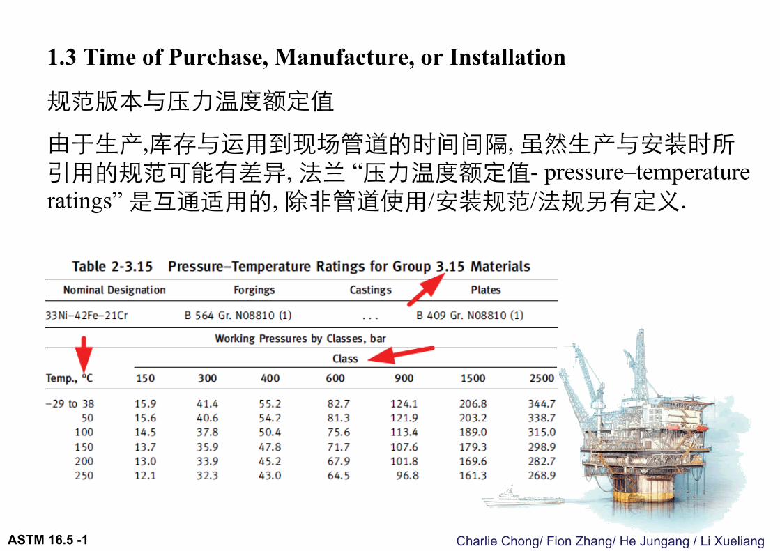
1.3 Time of Purchase, Manufacture, or Installation
规范版本与压力温度额定值
由于生产,库存与运用到现场管道的时间间隔, 虽然生产与安装时所引用的规范可能有差异, 法兰 “压力温度额定值- pressure–temperature ratings” 是互通适用的, 除非管道使用/安装规范/法规另有定义.
ASTM 16.5 -1

Charlie Chong/ Fion Zhang/ He Jungang / Li Xueliang
法兰 “压力温度额定值-“pressure–temperature ratings”
不受规范版本替代的影响
ASTM 16.5 -1
Charlie Chong/ Fion Zhang/ He Jungang / Li Xueliang
1.4 User Accountability 用户的责任This Standard cites duties and responsibilities that are to be assumed by the flange or flanged fitting user in the areas of, for example, application, installation, system hydrostatic testing, operation, and material selection.应用, 安装, 系统水压试验, 操作, 和材料的选择为用户责任.
1.5 Quality Systems 质量系统Requirements relating to the product manufacturer’s Quality System Program are described in Nonmandatory Appendix D.有关产品制造商的质量体系程序的要求- 非强制性附录D描述相关要求
ASTM 16.5 -1
Charlie Chong/ Fion Zhang/ He Jungang / Li Xueliang
1.6 Relevant Units 有关尺寸单位
This Standard states values in both metric and U.S. Customary units. As an exception, diameter of bolts and flange bolt holes are expressed in inch units only. These systems of units are to be regarded separately as standard. Within the text, the U.S. Customary units are shown in parentheses or in separate tables. The values stated in each system are not exact equivalents; therefore, it is required that each system of units be used independently of the other. Except for diameter of bolts and flange bolt holes, combining values from the two systems constitutes nonconformance with the Standard.
螺栓和法兰螺栓孔的直径 “只是” 以英制作为标准测量单位.
规范里的英制与公制, 被看作是不同的标准. 应当完全独立的运用. 同一个产品混合使用英制与公制导致不合格项.
ASTM 16.5 -1

Charlie Chong/ Fion Zhang/ He Jungang / Li Xueliang
规范里的英制与公制, 被看作是不同的独立标准, 不能混着运用在同一个产品上!除了螺栓孔与螺栓尺寸只是以英制为唯一测量规格
ASTM 16.5 -1
Charlie Chong/ Fion Zhang/ He Jungang / Li Xueliang
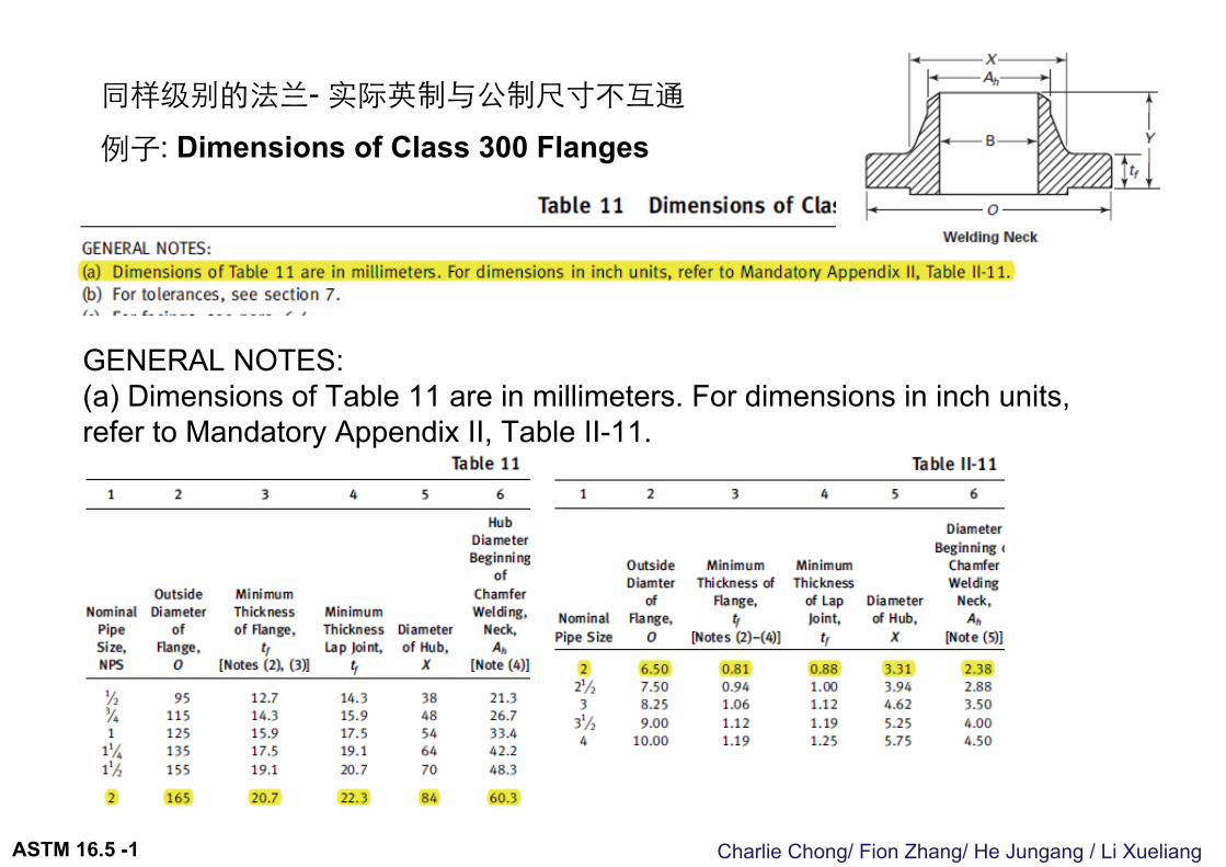
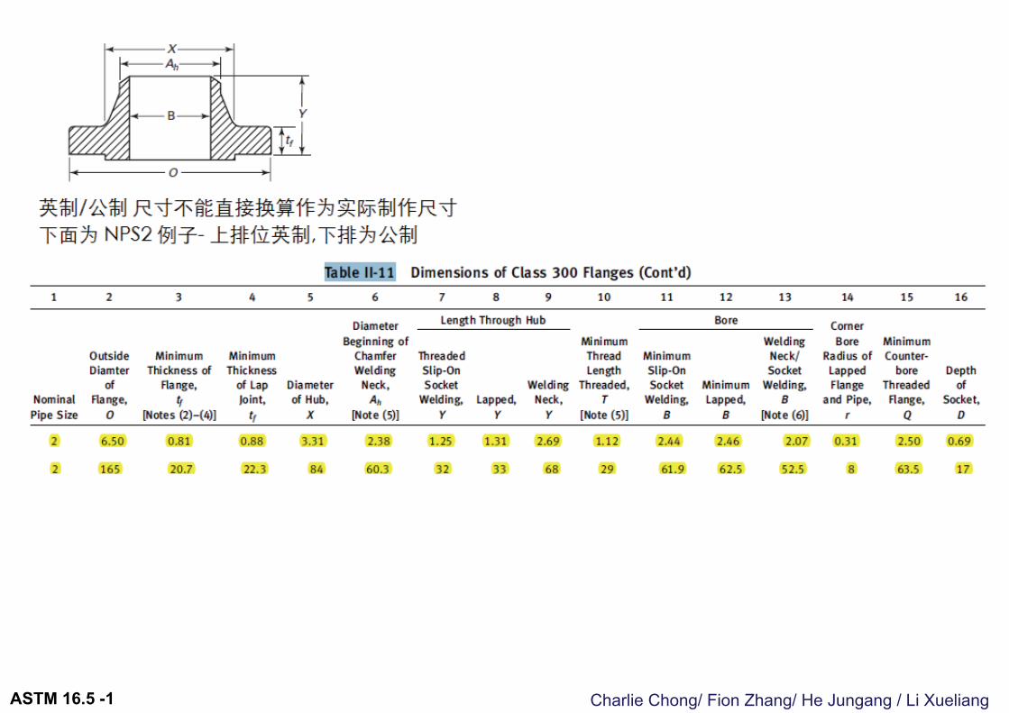
同样级别的法兰- 实际英制与公制尺寸不互通
例子: Dimensions of Class 300 Flanges
GENERAL NOTES:(a) Dimensions of Table 11 are in millimeters. For dimensions in inch units, refer to Mandatory Appendix II, Table II-11.
ASTM 16.5 -1
Charlie Chong/ Fion Zhang/ He Jungang / Li XueliangASTM 16.5 -1
Charlie Chong/ Fion Zhang/ He Jungang / Li Xueliang
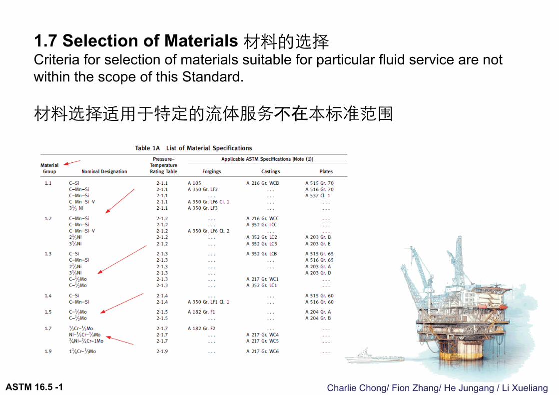
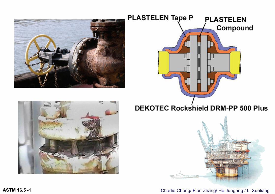
1.7 Selection of Materials 材料的选择Criteria for selection of materials suitable for particular fluid service are not within the scope of this Standard.
材料选择适用于特定的流体服务不在本标准范围
ASTM 16.5 -1
Charlie Chong/ Fion Zhang/ He Jungang / Li XueliangASTM 16.5 -1
Charlie Chong/ Fion Zhang/ He Jungang / Li Xueliang
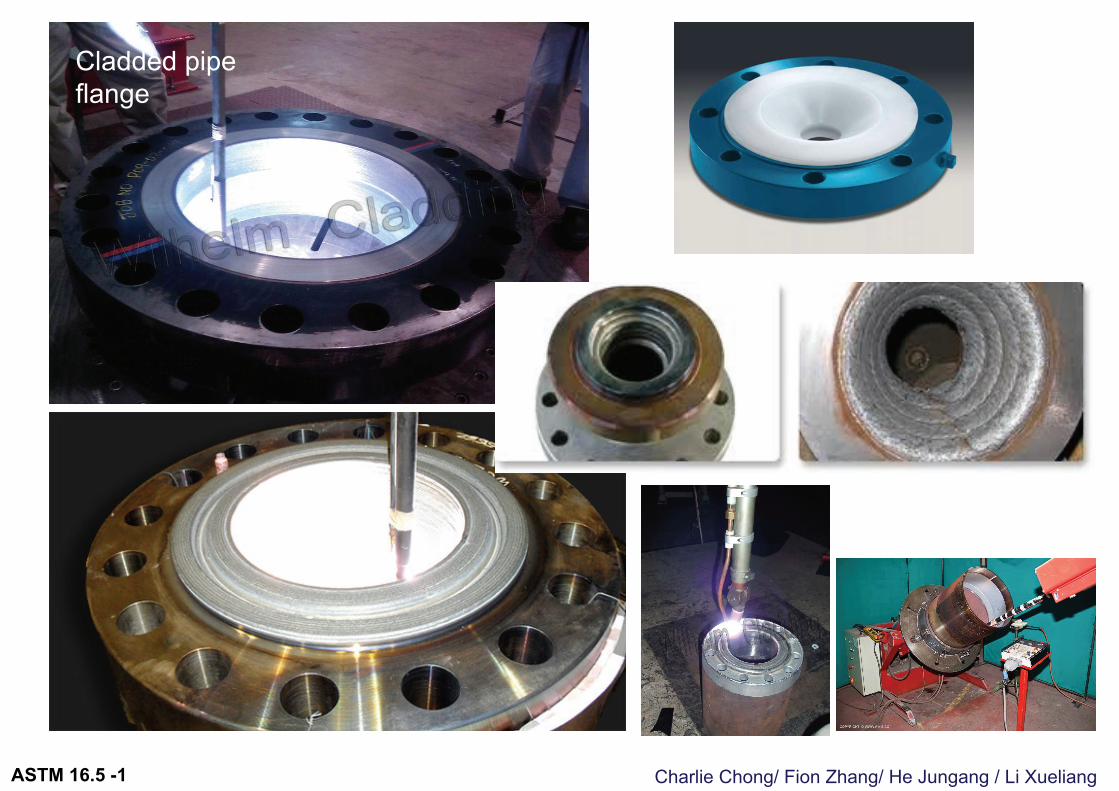
Cladded pipe flange
ASTM 16.5 -1
Charlie Chong/ Fion Zhang/ He Jungang / Li Xueliang
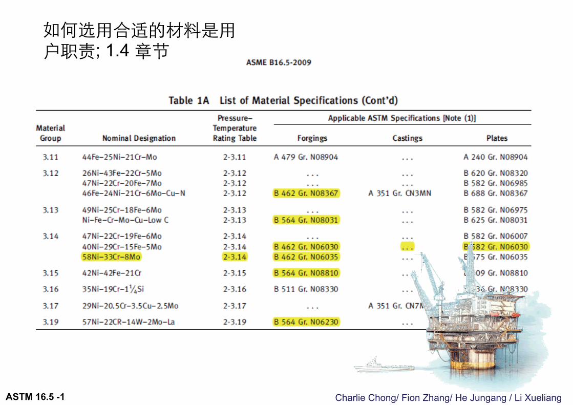
如何选用合适的材料是用户职责; 1.4 章节
ASTM 16.5 -1
Charlie Chong/ Fion Zhang/ He Jungang / Li Xueliang
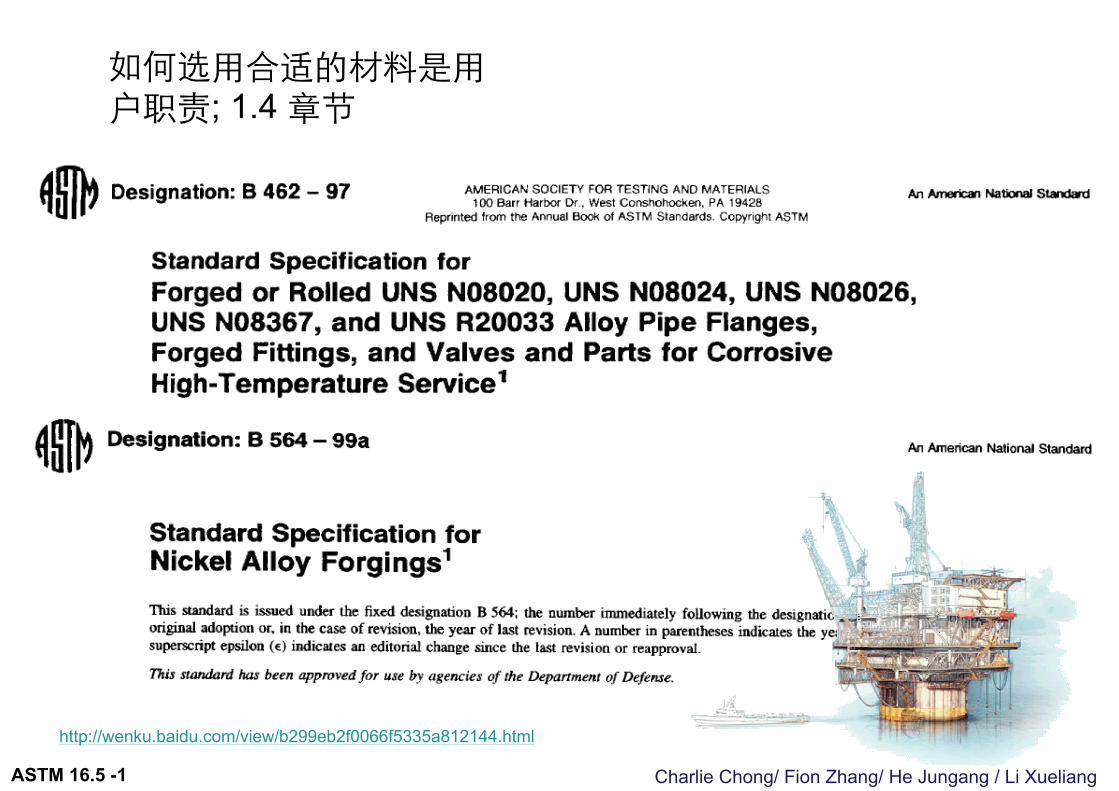
如何选用合适的材料是用户职责; 1.4 章节
http://wenku.baidu.com/view/b299eb2f0066f5335a812144.html
ASTM 16.5 -1
Charlie Chong/ Fion Zhang/ He Jungang / Li Xueliang
1.8 Convention 度量衡协定For the purpose of determining conformance with this Standard, the convention for fixing significant digits where limits, maximum and minimum values, are specified shall be rounded as defined in ASTM Practice E 29. This requires that an observed or calculated value shall be rounded off to the nearest unit in the last right-hand digit used for expressing the limit. Decimal values and tolerances do not imply a particular method of measurement.
尺寸精度许按照 ASTM Practice E29 用于量衡右边的数字最接近的规范限制小数点位数.
ASTM E29-2008 使用试验数据中重要数字以确定对规范的适应性
ASTM 16.5 -1
Charlie Chong/ Fion Zhang/ He Jungang / Li Xueliang
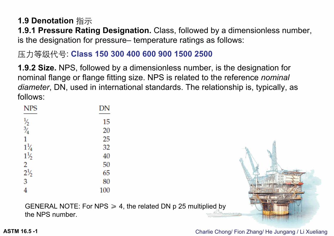
1.9 Denotation 指示1.9.1 Pressure Rating Designation. Class, followed by a dimensionless number, is the designation for pressure– temperature ratings as follows:压力等级代号: Class 150 300 400 600 900 1500 25001.9.2 Size. NPS, followed by a dimensionless number, is the designation for nominal flange or flange fitting size. NPS is related to the reference nominal diameter, DN, used in international standards. The relationship is, typically, as follows:
GENERAL NOTE: For NPS ≥ 4, the related DN p 25 multiplied by the NPS number.
ASTM 16.5 -1
Charlie Chong/ Fion Zhang/ He Jungang / Li XueliangASTM 16.5 -2
2 PRESSURE–TEMPERATURE RATINGS 压力温度额定值
Charlie Chong/ Fion Zhang/ He Jungang / Li Xueliang
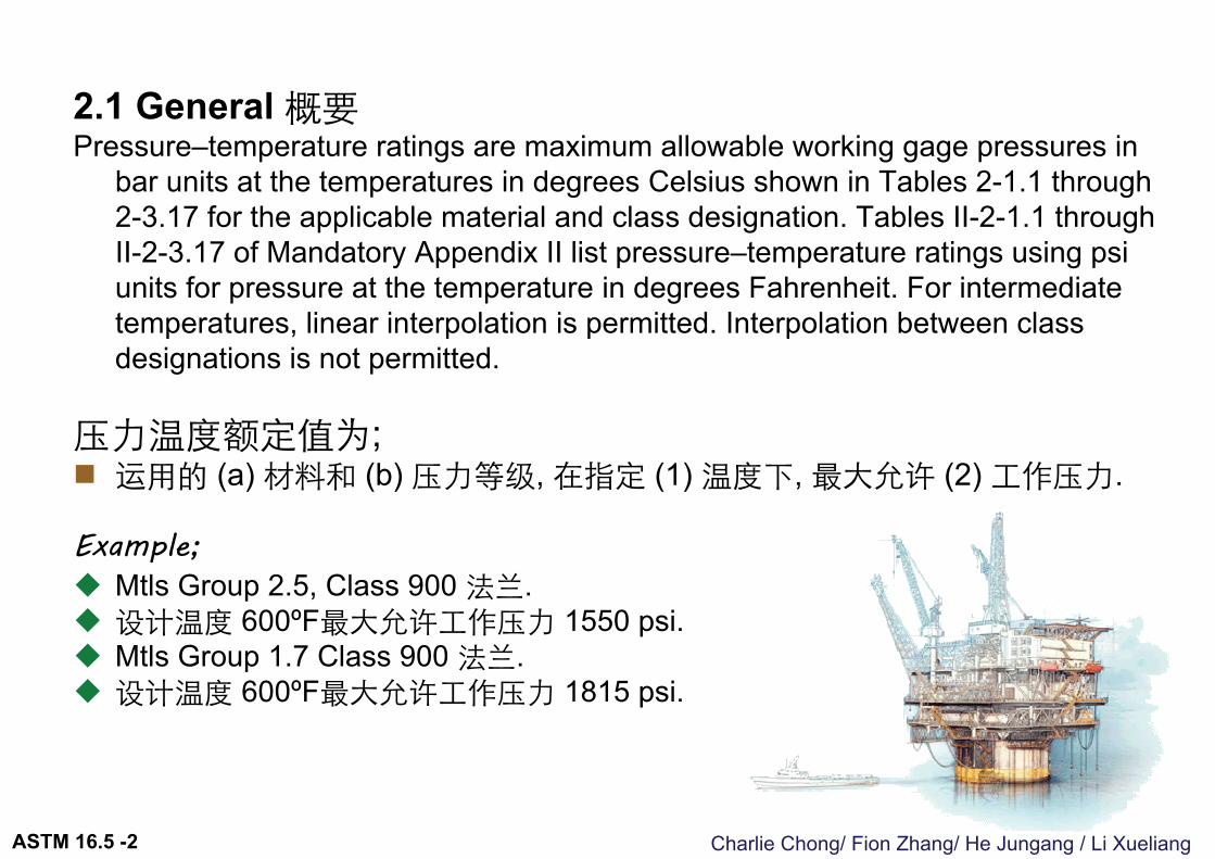
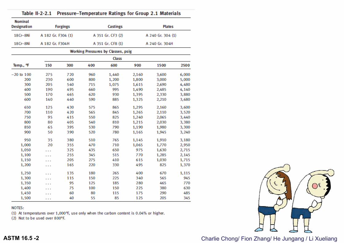
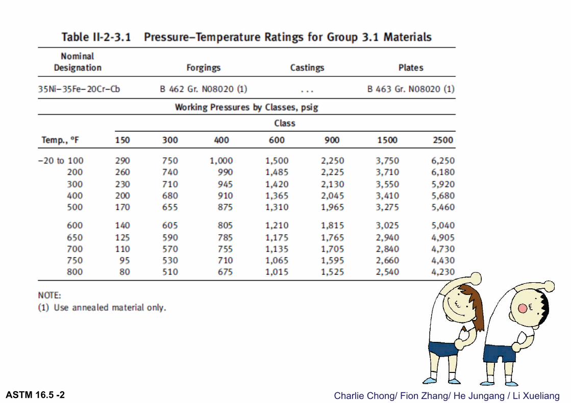
2.1 General 概要Pressure–temperature ratings are maximum allowable working gage pressures in
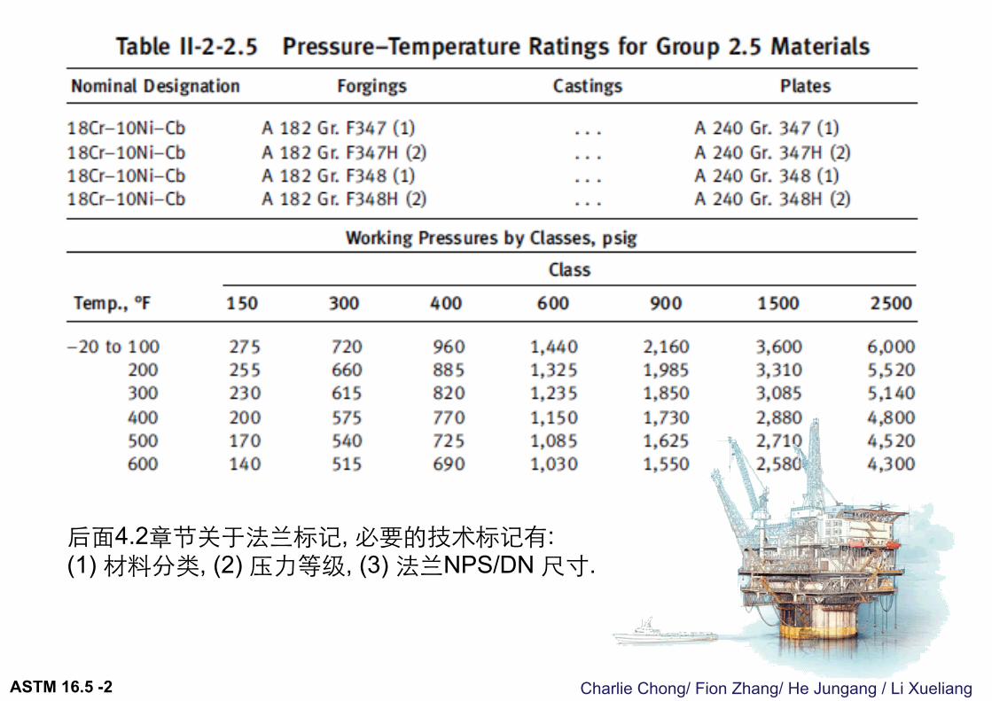
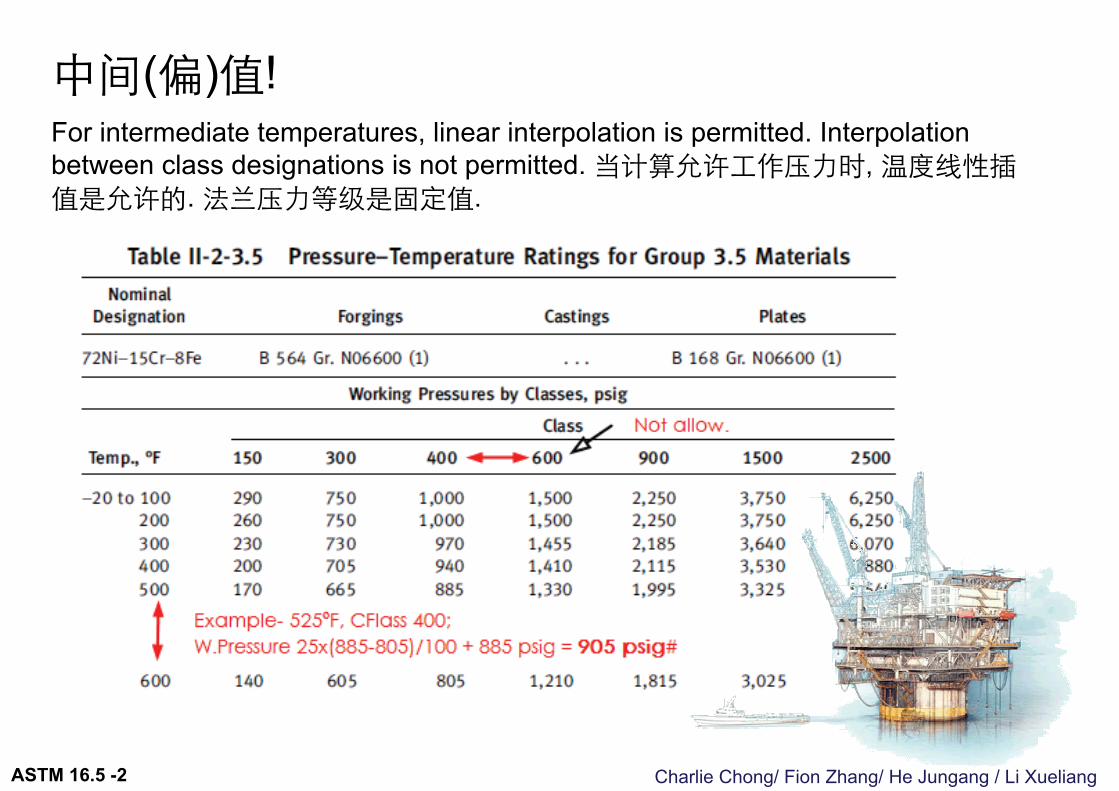
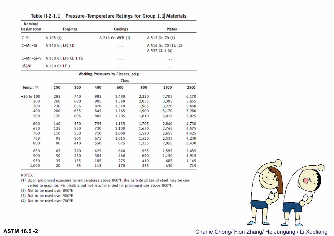
bar units at the temperatures in degrees Celsius shown in Tables 2-1.1 through 2-3.17 for the applicable material and class designation. Tables II-2-1.1 through II-2-3.17 of Mandatory Appendix II list pressure–temperature ratings using psi units for pressure at the temperature in degrees Fahrenheit. For intermediate temperatures, linear interpolation is permitted. Interpolation between class designations is not permitted.
压力温度额定值为; 运用的 (a) 材料和 (b) 压力等级, 在指定 (1) 温度下, 最大允许 (2) 工作压力.
Example; Mtls Group 2.5, Class 900 法兰. 设计温度 600ºF最大允许工作压力 1550 psi. Mtls Group 1.7 Class 900 法兰. 设计温度 600ºF最大允许工作压力 1815 psi.
ASTM 16.5 -2
Charlie Chong/ Fion Zhang/ He Jungang / Li Xueliang
后面4.2章节关于法兰标记, 必要的技术标记有: (1) 材料分类, (2) 压力等级, (3) 法兰NPS/DN 尺寸.
ASTM 16.5 -2
Charlie Chong/ Fion Zhang/ He Jungang / Li Xueliang
中间(偏)值!For intermediate temperatures, linear interpolation is permitted. Interpolation between class designations is not permitted. 当计算允许工作压力时, 温度线性插值是允许的. 法兰压力等级是固定值.
ASTM 16.5 -2
Charlie Chong/ Fion Zhang/ He Jungang / Li Xueliang
大家动一动-下面三页为互动题
法兰三个关键基本信息;
NPS
Mtls
Rating
认识压力温度额定值;
ASTM 16.5 -2
Charlie Chong/ Fion Zhang/ He Jungang / Li XueliangASTM 16.5 -2
Charlie Chong/ Fion Zhang/ He Jungang / Li XueliangASTM 16.5 -2
Charlie Chong/ Fion Zhang/ He Jungang / Li XueliangASTM 16.5 -2
Charlie Chong/ Fion Zhang/ He Jungang / Li Xueliang
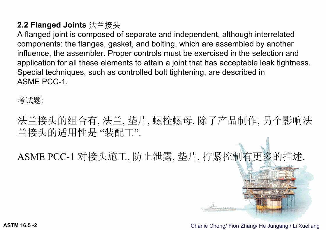
2.2 Flanged Joints 法兰接头A flanged joint is composed of separate and independent, although interrelated components: the flanges, gasket, and bolting, which are assembled by anotherinfluence, the assembler. Proper controls must be exercised in the selection and application for all these elements to attain a joint that has acceptable leak tightness.Special techniques, such as controlled bolt tightening, are described in ASME PCC-1.
考试题:
法兰接头的组合有, 法兰, 垫片, 螺栓螺母. 除了产品制作, 另个影响法兰接头的适用性是 “装配工”.
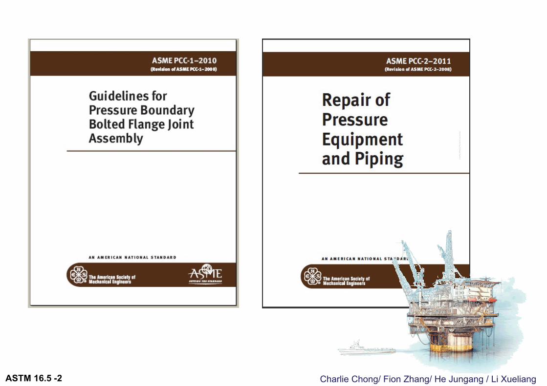
ASME PCC-1 对接头施工, 防止泄露, 垫片, 拧紧控制有更多的描述.
ASTM 16.5 -2
Charlie Chong/ Fion Zhang/ He Jungang / Li XueliangASTM 16.5 -2
Charlie Chong/ Fion Zhang/ He Jungang / Li Xueliang
2.3 Ratings of Flanged Joints 法兰接头的额定值2.3.1 Basis. Pressure–temperature ratings apply to flanged joints that conform to the limitations on bolting in para. 5.3 and on gaskets in para. 5.4, which are made up in accordance with good practice for alignment and assembly (see para. 2.2). Use of these ratings for flanged joints not conforming to these limitations is the responsibility of the user.
法兰接头的额定值:法兰接头的 “压力–温度额定值” 应当符合(1) 法兰本身, (2) 螺栓, (3) 垫片, 的综合要求与限制.
2.3.2 Mixed Flanged Joints.混合法兰接头If the two flanges in a flanged joint do not have the same pressure–temperature rating, the rating of the joint at any temperature is the lower of the two flange ratings at that temperature.
不同压力等级的混合法兰接头的额定值, 为较低的法兰额定值.
ASTM 16.5 -2
Charlie Chong/ Fion Zhang/ He Jungang / Li Xueliang
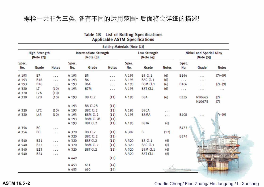
螺栓一共非为三类, 各有不同的运用范围- 后面将会详细的描述!
ASTM 16.5 -2
Charlie Chong/ Fion Zhang/ He Jungang / Li Xueliang
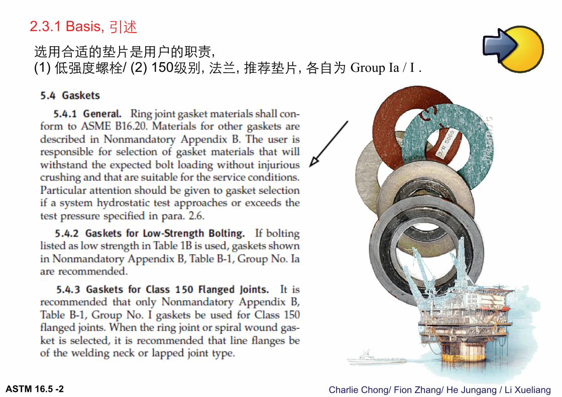
2.3.1 Basis, 引述选用合适的垫片是用户的职责, (1) 低强度螺栓/ (2) 150级别, 法兰, 推荐垫片, 各自为 Group Ia / I .
ASTM 16.5 -2
Charlie Chong/ Fion Zhang/ He Jungang / Li XueliangASTM 16.5 -2

Charlie Chong/ Fion Zhang/ He Jungang / Li Xueliang
2.4 Rating Temperature 温度额定The temperature shown for a corresponding pressure rating is the temperature of
the pressure-containing shell of the component. In general, this temperature is the same as that of the contained fluid. Use of a pressure rating corresponding to a temperature other than that of the contained fluid is the responsibility of the user, subject to the requirements of applicable codes and regulations. For any temperature below −29ºC (−20ºF), the rating shall be no greater than the rating shown for −29ºC (−20ºF) (see also paras. 2.5.3 and 5.1.2).
规范里的温度额定值为, 承压组件(壳)的温度, 一般这温度等同媒介流体温度. 其他核定温度方法是用户的职责.
规范压力-温度额定值,最小温度为−20ºF, 实际使用低于−20ºF, 最大工作允许压力不能大于表格设定的; −20ºF相应的工作压力.
低温材料运用在−7ºC或更高可能必须通过低温冲击试验, 然而这是用户的职责确保上述实验是否执行. (5.1.2)
ASTM 16.5 -2
Charlie Chong/ Fion Zhang/ He Jungang / Li Xueliang
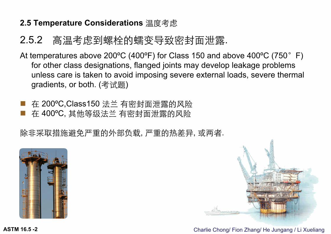
2.5 Temperature Considerations 温度考虑
2.5.2 高温考虑到螺栓的蠕变导致密封面泄露.At temperatures above 200ºC (400ºF) for Class 150 and above 400ºC (750°F)
for other class designations, flanged joints may develop leakage problems unless care is taken to avoid imposing severe external loads, severe thermal gradients, or both. (考试题)
在 200ºC,Class150 法兰有密封面泄露的风险 在 400ºC, 其他等级法兰有密封面泄露的风险
除非采取措施避免严重的外部负载, 严重的热差异, 或两者.
ASTM 16.5 -2
Charlie Chong/ Fion Zhang/ He Jungang / Li XueliangASTM 16.5 -2
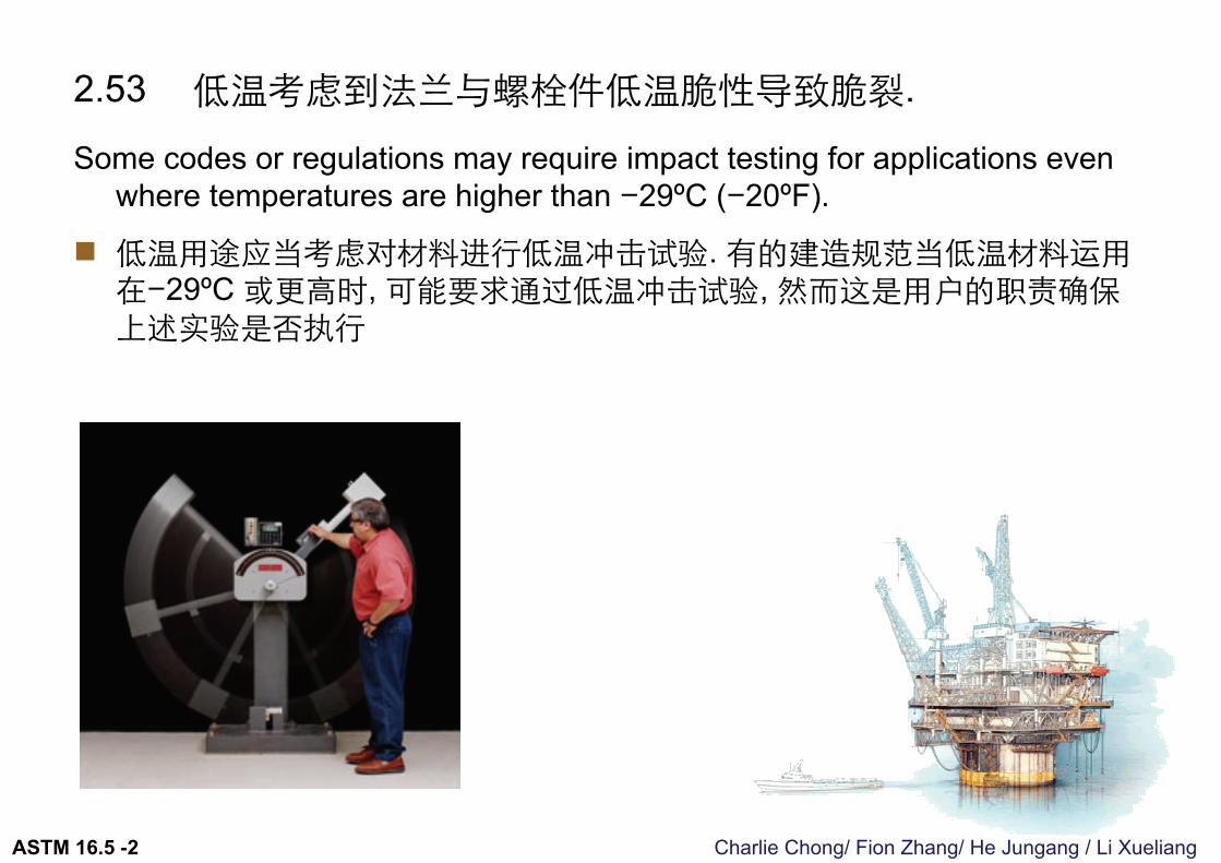
2.53 低温考虑到法兰与螺栓件低温脆性导致脆裂.
Some codes or regulations may require impact testing for applications even where temperatures are higher than −29ºC (−20ºF).
低温用途应当考虑对材料进行低温冲击试验. 有的建造规范当低温材料运用在−29ºC 或更高时, 可能要求通过低温冲击试验, 然而这是用户的职责确保上述实验是否执行

Charlie Chong/ Fion Zhang/ He Jungang / Li XueliangASTM 16.5 -2
Charlie Chong/ Fion Zhang/ He Jungang / Li Xueliang
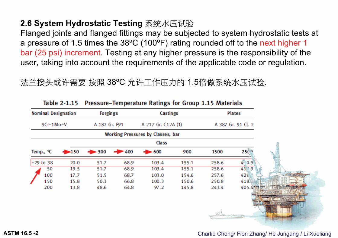
2.6 System Hydrostatic Testing 系统水压试验Flanged joints and flanged fittings may be subjected to system hydrostatic tests at a pressure of 1.5 times the 38ºC (100ºF) rating rounded off to the next higher 1 bar (25 psi) increment. Testing at any higher pressure is the responsibility of the user, taking into account the requirements of the applicable code or regulation.
法兰接头或许需要按照 38ºC 允许工作压力的 1.5倍做系统水压试验.
ASTM 16.5 -2
Charlie Chong/ Fion Zhang/ He Jungang / Li XueliangASTM 16.5 -2
Charlie Chong/ Fion Zhang/ He Jungang / Li Xueliang
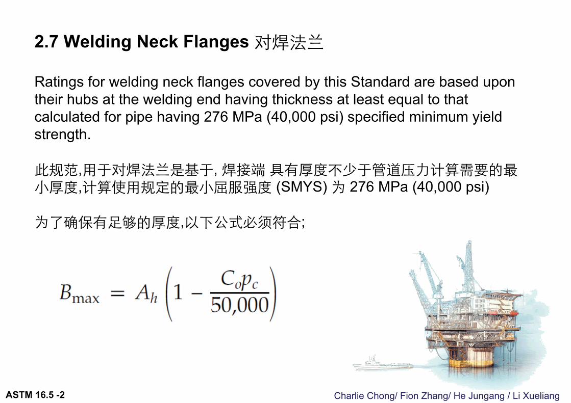
2.7 Welding Neck Flanges 对焊法兰
Ratings for welding neck flanges covered by this Standard are based upon their hubs at the welding end having thickness at least equal to that calculated for pipe having 276 MPa (40,000 psi) specified minimum yield strength.
此规范,用于对焊法兰是基于, 焊接端具有厚度不少于管道压力计算需要的最小厚度,计算使用规定的最小屈服强度 (SMYS) 为 276 MPa (40,000 psi)
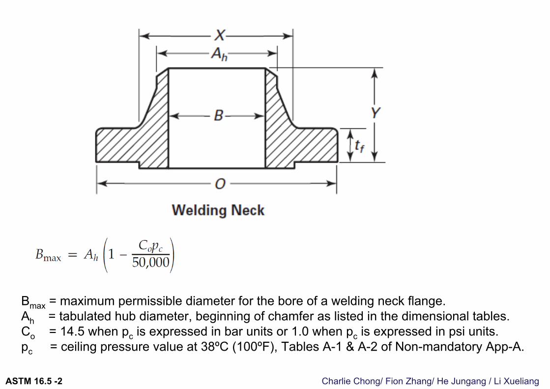
为了确保有足够的厚度,以下公式必须符合;
ASTM 16.5 -2
Charlie Chong/ Fion Zhang/ He Jungang / Li Xueliang
Bmax = maximum permissible diameter for the bore of a welding neck flange.Ah = tabulated hub diameter, beginning of chamfer as listed in the dimensional tables.Co = 14.5 when pc is expressed in bar units or 1.0 when pc is expressed in psi units.pc = ceiling pressure value at 38ºC (100ºF), Tables A-1 & A-2 of Non-mandatory App-A.
ASTM 16.5 -2
Charlie Chong/ Fion Zhang/ He Jungang / Li Xueliang
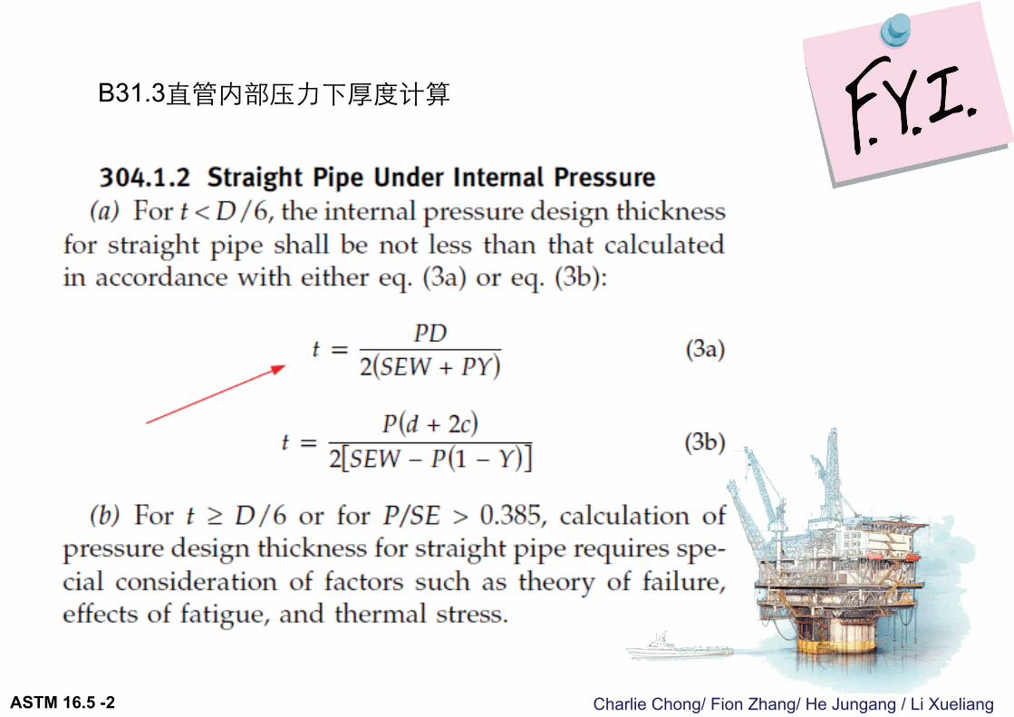
B31.3直管内部压力下厚度计算
ASTM 16.5 -2
Charlie Chong/ Fion Zhang/ He Jungang / Li Xueliang
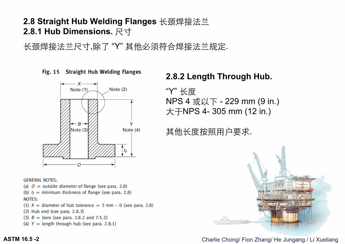
2.8 Straight Hub Welding Flanges 长颈焊接法兰2.8.1 Hub Dimensions. 尺寸
长颈焊接法兰尺寸,除了 “Y” 其他必须符合焊接法兰规定.
2.8.2 Length Through Hub. “Y” 长度NPS 4 或以下 - 229 mm (9 in.) 大于NPS 4- 305 mm (12 in.)
其他长度按照用户要求.
ASTM 16.5 -2
Charlie Chong/ Fion Zhang/ He Jungang / Li Xueliang
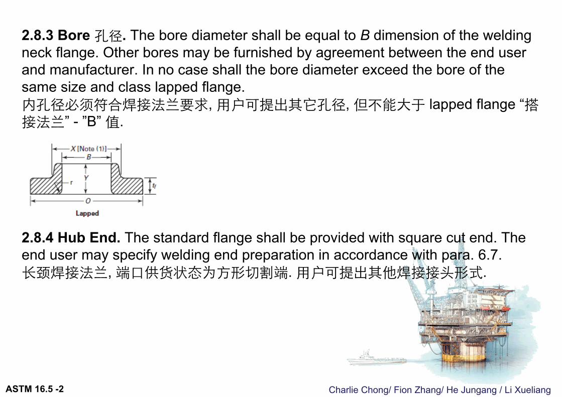
2.8.3 Bore 孔径. The bore diameter shall be equal to B dimension of the welding neck flange. Other bores may be furnished by agreement between the end user and manufacturer. In no case shall the bore diameter exceed the bore of the same size and class lapped flange.内孔径必须符合焊接法兰要求, 用户可提出其它孔径, 但不能大于 lapped flange “搭接法兰” - ”B” 值.
2.8.4 Hub End. The standard flange shall be provided with square cut end. The end user may specify welding end preparation in accordance with para. 6.7.长颈焊接法兰, 端口供货状态为方形切割端. 用户可提出其他焊接接头形式.
ASTM 16.5 -2
Charlie Chong/ Fion Zhang/ He Jungang / Li Xueliang
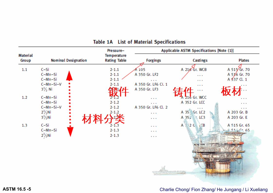
2.9 Multiple Material Grades 多材料等级Material for flanges and flanged fittings may meet the requirements of more than one specification or the requirements of more than one grade of a specification listed in Table 1A. In either case, the pressure–temperature ratings for any of these specifications or grades may be used provided the material is marked in accordance with para. 4.2.8.
当法兰材料符合超过 Table1A 材料等级时, 压力温度额定值为相应的法兰上标记的材料等级
ASTM 16.5 -2

Charlie Chong/ Fion Zhang/ He Jungang / Li XueliangASTM 16.5 -2
Charlie Chong/ Fion Zhang/ He Jungang / Li XueliangASTM 16.5 -3
3 COMPONENT SIZE元件尺寸
Charlie Chong/ Fion Zhang/ He Jungang / Li XueliangASTM 16.5 -3

Charlie Chong/ Fion Zhang/ He Jungang / Li XueliangASTM 16.5 -3
Charlie Chong/ Fion Zhang/ He Jungang / Li XueliangASTM 16.5 -3
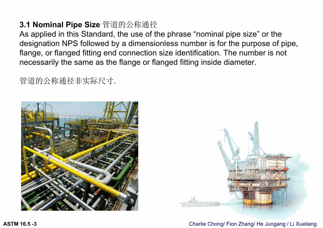
3.1 Nominal Pipe Size 管道的公称通径As applied in this Standard, the use of the phrase “nominal pipe size” or the designation NPS followed by a dimensionless number is for the purpose of pipe,flange, or flanged fitting end connection size identification. The number is not necessarily the same as the flange or flanged fitting inside diameter.
管道的公称通径非实际尺寸.
Charlie Chong/ Fion Zhang/ He Jungang / Li XueliangASTM 16.5 -3
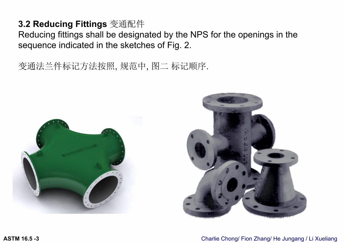
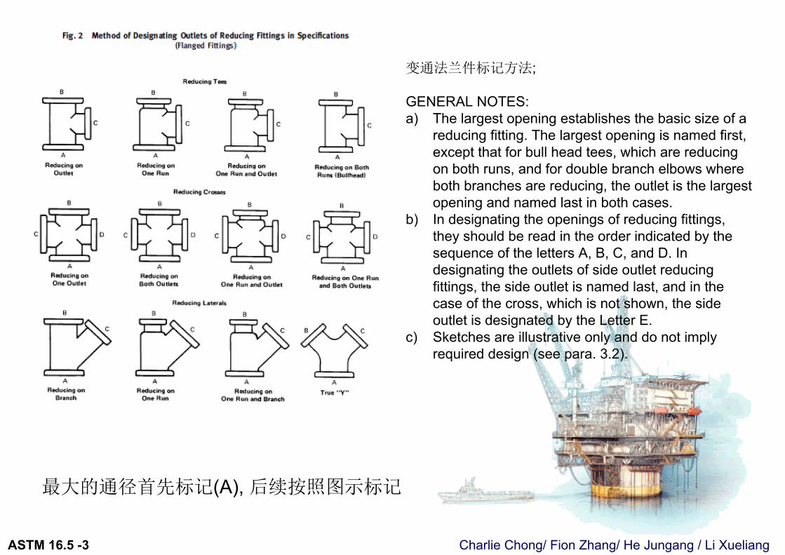
3.2 Reducing Fittings 变通配件Reducing fittings shall be designated by the NPS for the openings in the sequence indicated in the sketches of Fig. 2.
变通法兰件标记方法按照, 规范中, 图二 标记顺序.
Charlie Chong/ Fion Zhang/ He Jungang / Li XueliangASTM 16.5 -3
变通法兰件标记方法;
GENERAL NOTES:a) The largest opening establishes the basic size of a
reducing fitting. The largest opening is named first, except that for bull head tees, which are reducing on both runs, and for double branch elbows where both branches are reducing, the outlet is the largest opening and named last in both cases.
b) In designating the openings of reducing fittings, they should be read in the order indicated by the sequence of the letters A, B, C, and D. In designating the outlets of side outlet reducing fittings, the side outlet is named last, and in the case of the cross, which is not shown, the side outlet is designated by the Letter E.
c) Sketches are illustrative only and do not imply required design (see para. 3.2).
最大的通径首先标记(A), 后续按照图示标记
Charlie Chong/ Fion Zhang/ He Jungang / Li XueliangASTM 16.5 -3
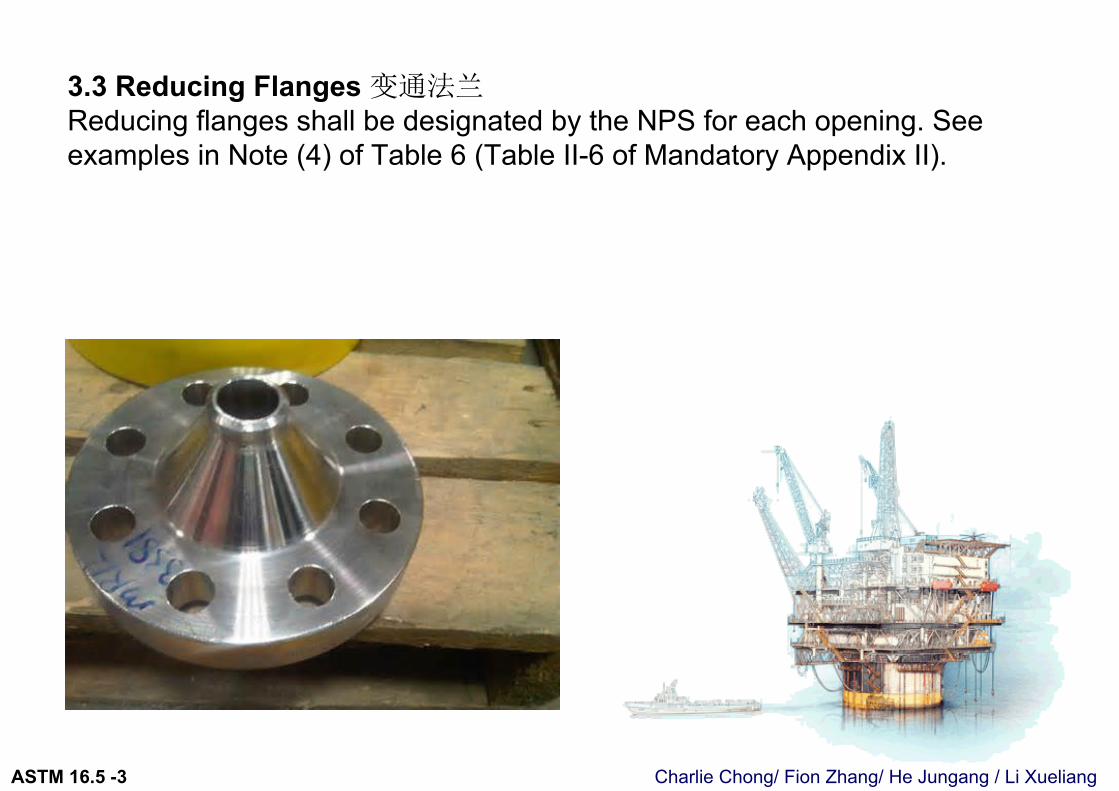
3.3 Reducing Flanges 变通法兰Reducing flanges shall be designated by the NPS for each opening. See examples in Note (4) of Table 6 (Table II-6 of Mandatory Appendix II).
Charlie Chong/ Fion Zhang/ He Jungang / Li XueliangASTM 16.5 -3
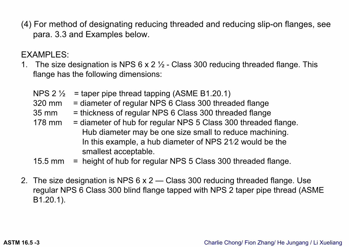
(4) For method of designating reducing threaded and reducing slip-on flanges, see para. 3.3 and Examples below.
EXAMPLES:1. The size designation is NPS 6 x 2 ½ - Class 300 reducing threaded flange. This
flange has the following dimensions:
NPS 2 ½ = taper pipe thread tapping (ASME B1.20.1) 320 mm = diameter of regular NPS 6 Class 300 threaded flange35 mm = thickness of regular NPS 6 Class 300 threaded flange 178 mm = diameter of hub for regular NPS 5 Class 300 threaded flange.
Hub diameter may be one size small to reduce machining. In this example, a hub diameter of NPS 21⁄2 would be thesmallest acceptable.
15.5 mm = height of hub for regular NPS 5 Class 300 threaded flange.
2. The size designation is NPS 6 x 2 — Class 300 reducing threaded flange. Use regular NPS 6 Class 300 blind flange tapped with NPS 2 taper pipe thread (ASME B1.20.1).
Charlie Chong/ Fion Zhang/ He Jungang / Li XueliangASTM 16.5 -3
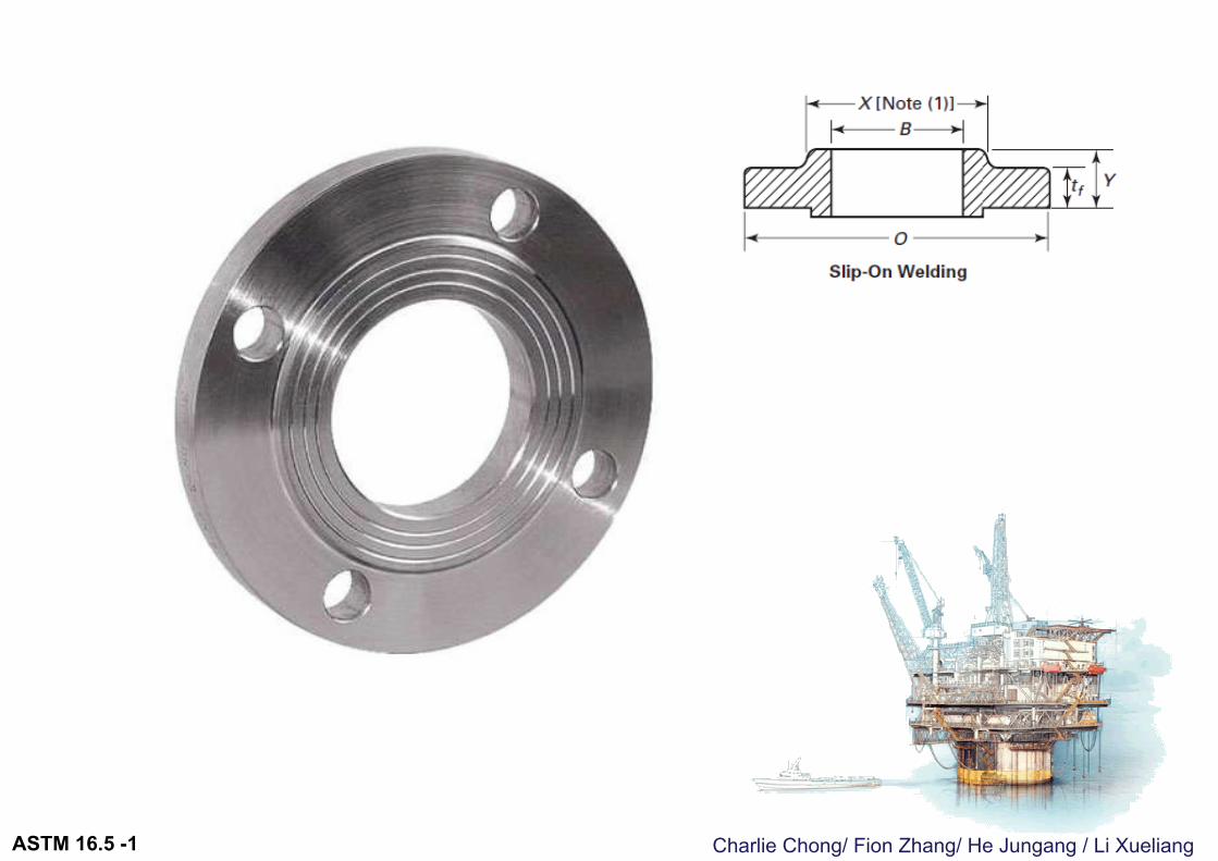
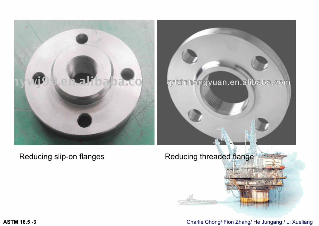
Reducing slip-on flanges Reducing threaded flange
Charlie Chong/ Fion Zhang/ He Jungang / Li XueliangASTM 16.5 -3
4 MARKING标记
Charlie Chong/ Fion Zhang/ He Jungang / Li XueliangASTM 16.5 -3
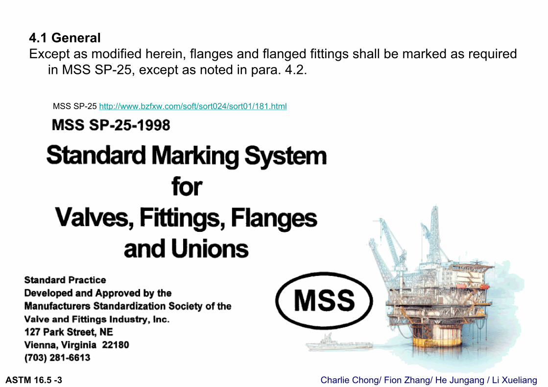
4.1 GeneralExcept as modified herein, flanges and flanged fittings shall be marked as required
in MSS SP-25, except as noted in para. 4.2.
MSS SP-25 http://www.bzfxw.com/soft/sort024/sort01/181.html
Charlie Chong/ Fion Zhang/ He Jungang / Li XueliangASTM 16.5 -3
4.2 Identification Markings 法兰,法兰件标示4.2.1 Name. The manufacturer’s name or trademark shall be applied.制造商的名称或商标必须体现
4.2.2 Material. Material shall be identified in the following way: 法兰上的材料标号
a) Cast flanges and flanged fittings shall be marked with the ASTM specification, grade identification symbol (letters and numbers), and the melt number or melt identification. ASTM规格和等级与炉号
b) Plate flanges, forged flanges, and flanged fittings shall be marked with the ASTM specification number and grade identification symbol. ASTM规格和等级
c) A manufacturer may supplement these mandatory material indications with his trade designation for the material grade, but confusion of symbols shall be avoided. 也可以加上商业牌号,但确保不造成混乱.
d) For flanges and flanged fittings manufactured from material that meets the requirements of more than one specification or grade of a specification listed in Table 1A, see para. 4.2.8. 符合材料多标准参考 4.2.8
Charlie Chong/ Fion Zhang/ He Jungang / Li XueliangASTM 16.5 -3
4.2.3 Rating Designation. The flange or flanged fitting shall be marked with the number that corresponds to its pressure rating class designation (i.e., 150, 300,
400, 600, 900, 1500, or 2500).
压力等级代号150, 300, 400, 600, 900, 1500, or 2500
4.2.4 Conformance. 符合性(达标)The designation B16 or B16.5 shall be applied to the flange or flanged fitting,
preferably located adjacent to the class designation, to indicate conformance to this Standard. The use of the prefix ASME is optional.
B16 或 B16.5表明符合本标准, ASME 字眼为可选性
Charlie Chong/ Fion Zhang/ He Jungang / Li XueliangASTM 16.5 -3
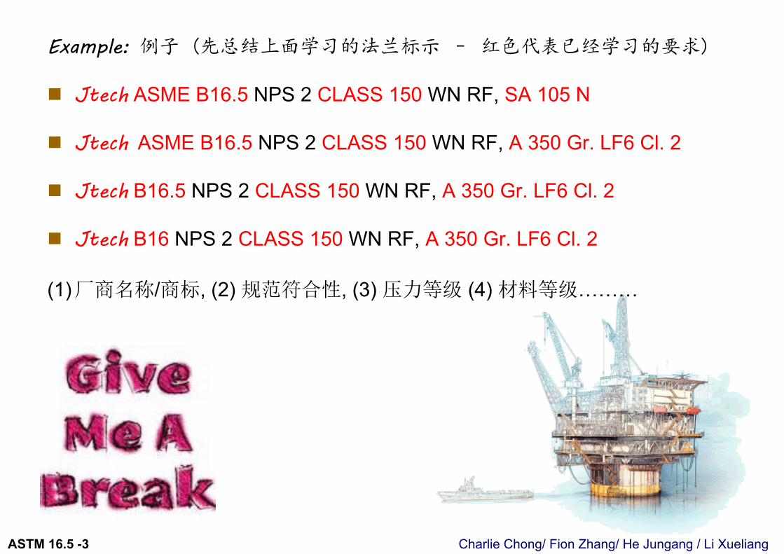
Example: 例子 (先总结上面学习的法兰标示 – 红色代表已经学习的要求)
Jtech ASME B16.5 NPS 2 CLASS 150 WN RF, SA 105 N
Jtech ASME B16.5 NPS 2 CLASS 150 WN RF, A 350 Gr. LF6 Cl. 2
Jtech B16.5 NPS 2 CLASS 150 WN RF, A 350 Gr. LF6 Cl. 2
Jtech B16 NPS 2 CLASS 150 WN RF, A 350 Gr. LF6 Cl. 2
(1)厂商名称/商标, (2) 规范符合性, (3) 压力等级 (4) 材料等级………
Charlie Chong/ Fion Zhang/ He Jungang / Li XueliangASTM 16.5 -3
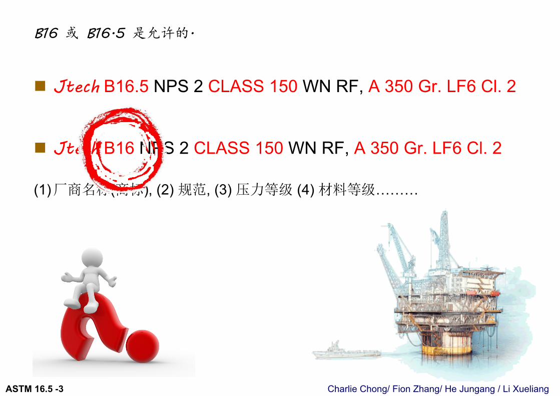
B16 或 B16.5 是允许的.
Jtech B16.5 NPS 2 CLASS 150 WN RF, A 350 Gr. LF6 Cl. 2
Jtech B16 NPS 2 CLASS 150 WN RF, A 350 Gr. LF6 Cl. 2
(1)厂商名称(商标), (2) 规范, (3) 压力等级 (4) 材料等级………
Charlie Chong/ Fion Zhang/ He Jungang / Li XueliangASTM 16.5 -3
ASME B16 系列
Charlie Chong/ Fion Zhang/ He Jungang / Li XueliangASTM 16.5 -3
4.2.5 Temperature. Temperature markings are not required on flanges or flanged fittings; however, if marked, the temperature shall be shown with its corresponding tabulated pressure rating for the material. (考试题)
温度标记不在法兰或法兰配件要求.如果标记, 温度应显示其相应的材料等级表, 允许工作压力.
Charlie Chong/ Fion Zhang/ He Jungang / Li XueliangASTM 16.5 -3
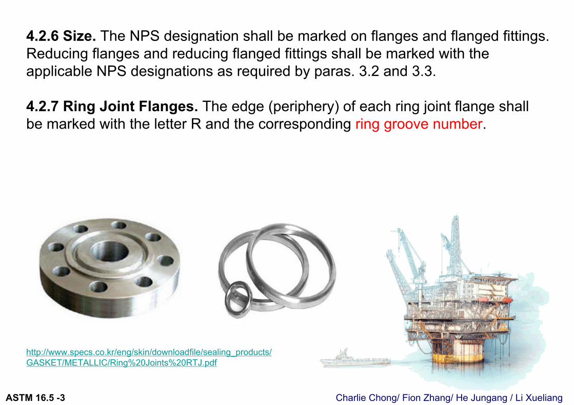
4.2.6 Size. The NPS designation shall be marked on flanges and flanged fittings. Reducing flanges and reducing flanged fittings shall be marked with the applicable NPS designations as required by paras. 3.2 and 3.3.
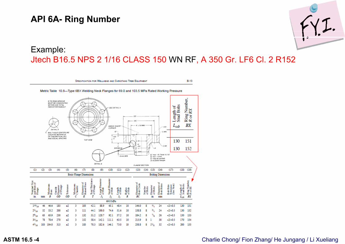
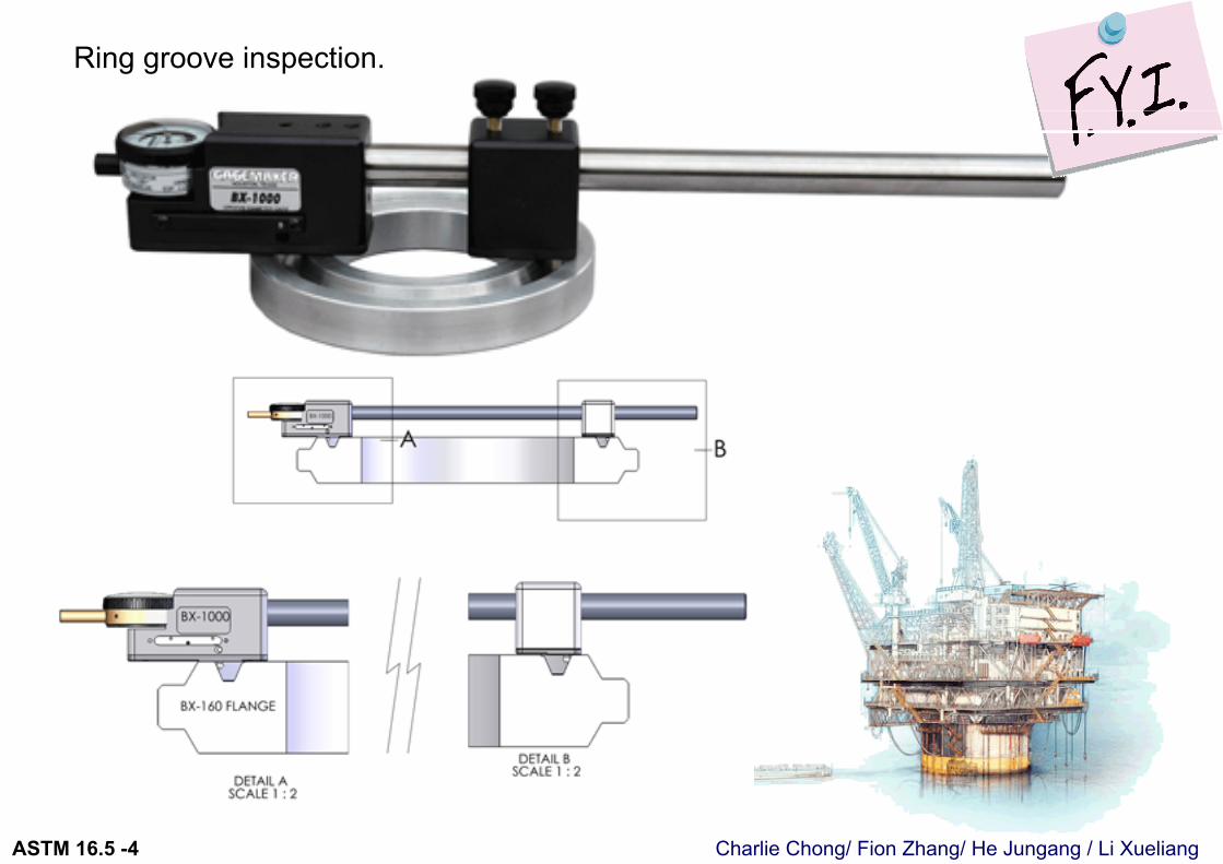
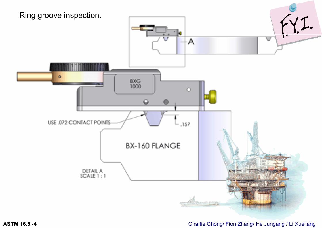
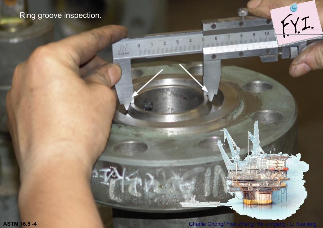
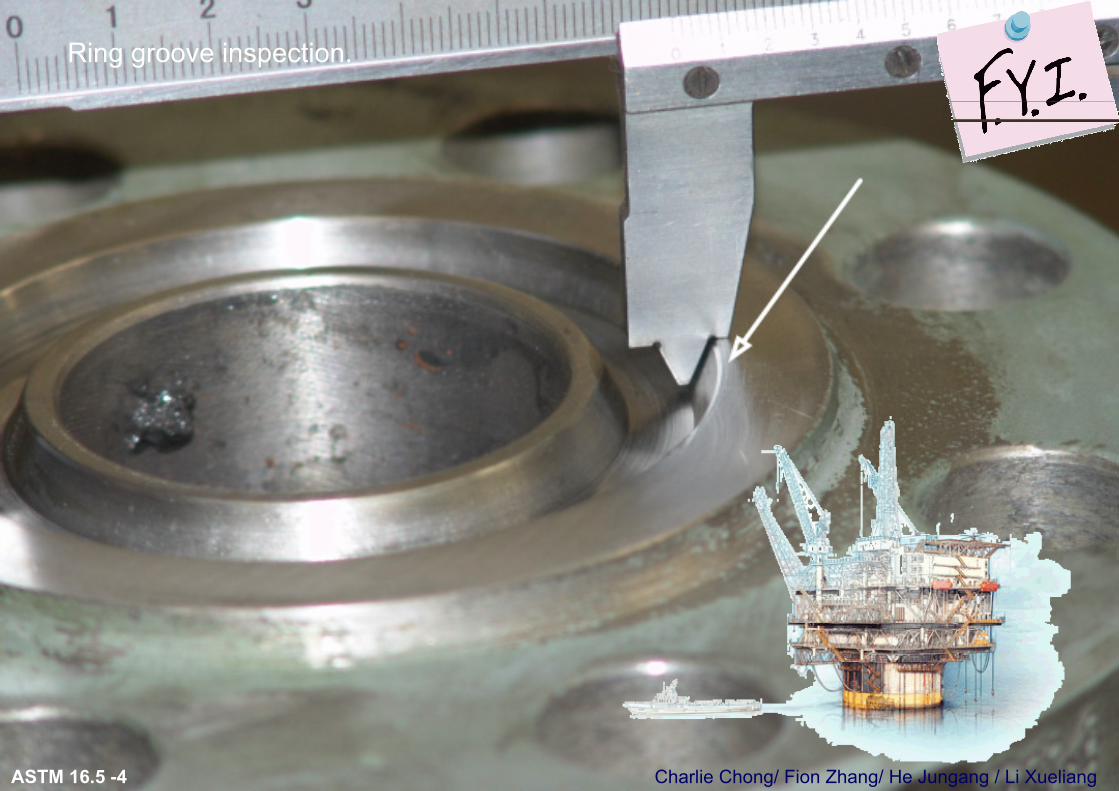
4.2.7 Ring Joint Flanges. The edge (periphery) of each ring joint flange shall be marked with the letter R and the corresponding ring groove number.
http://www.specs.co.kr/eng/skin/downloadfile/sealing_products/GASKET/METALLIC/Ring%20Joints%20RTJ.pdf
Charlie Chong/ Fion Zhang/ He Jungang / Li XueliangASTM 16.5 -4
Ring joint gaskets are fitted in ring groove type flanges and are manufactured in accordance with API-6A and ANSI B16.2
specifications.The dimensions are standardized and require specially grooved flanges. The octagonal cross section has a higher sealing efficiency than the oval and would be the preferred gasket. RTJ’s have “R” numbers assigned to them for pipe size and pressure class identification. Stock materials include soft iron, low carbon steel, 4-6 chrome (f5), 304, 304L, 316, 316L, 347, Monel, Inconel and Incoloy.
Charlie Chong/ Fion Zhang/ He Jungang / Li XueliangASTM 16.5 -4
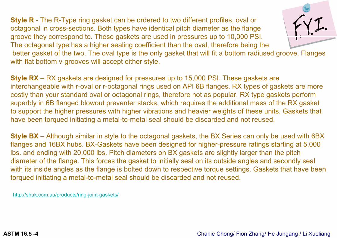
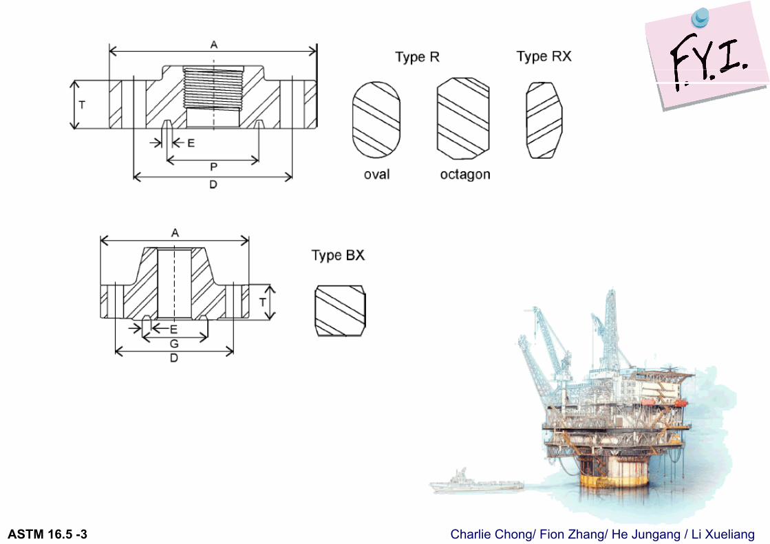
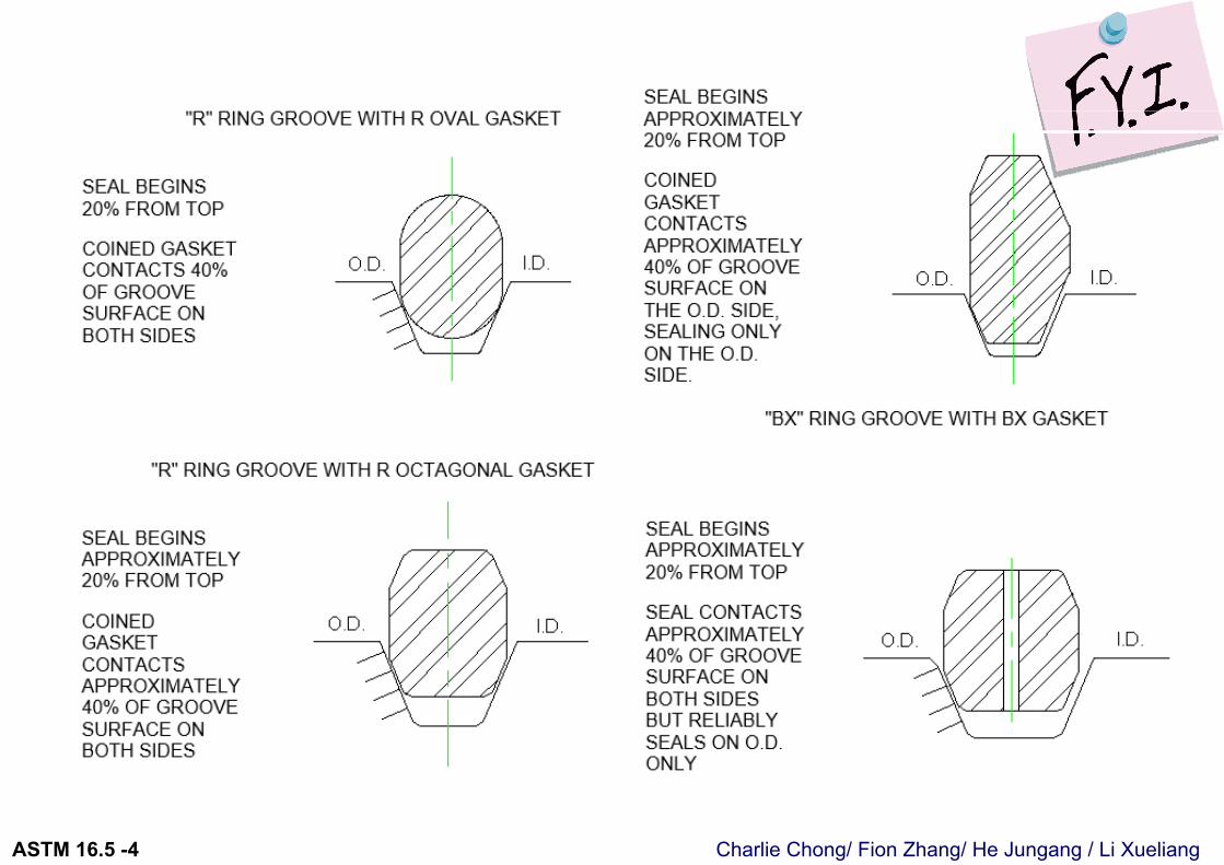
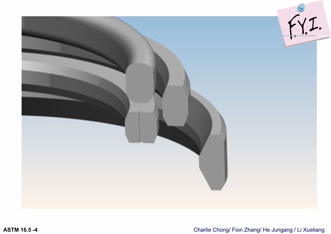
Style R - The R-Type ring gasket can be ordered to two different profiles, oval or octagonal in cross-sections. Both types have identical pitch diameter as the flangegroove they correspond to. These gaskets are used in pressures up to 10,000 PSI. The octagonal type has a higher sealing coefficient than the oval, therefore being thebetter gasket of the two. The oval type is the only gasket that will fit a bottom radiused groove. Flanges
with flat bottom v-grooves will accept either style.
Style RX – RX gaskets are designed for pressures up to 15,000 PSI. These gaskets are interchangeable with r-oval or r-octagonal rings used on API 6B flanges. RX types of gaskets are more costly than your standard oval or octagonal rings, therefore not as popular. RX type gaskets perform superbly in 6B flanged blowout preventer stacks, which requires the additional mass of the RX gasket to support the higher pressures with higher vibrations and heavier weights of these units. Gaskets that have been torqued initiating a metal-to-metal seal should be discarded and not reused.
Style BX – Although similar in style to the octagonal gaskets, the BX Series can only be used with 6BX flanges and 16BX hubs. BX-Gaskets have been designed for higher-pressure ratings starting at 5,000 lbs. and ending with 20,000 lbs. Pitch diameters on BX gaskets are slightly larger than the pitch diameter of the flange. This forces the gasket to initially seal on its outside angles and secondly seal with its inside angles as the flange is bolted down to respective torque settings. Gaskets that have been torqued initiating a metal-to-metal seal should be discarded and not reused.
http://shuk.com.au/products/ring-joint-gaskets/
Charlie Chong/ Fion Zhang/ He Jungang / Li XueliangASTM 16.5 -3
Charlie Chong/ Fion Zhang/ He Jungang / Li XueliangASTM 16.5 -4
Charlie Chong/ Fion Zhang/ He Jungang / Li XueliangASTM 16.5 -4
Charlie Chong/ Fion Zhang/ He Jungang / Li XueliangASTM 16.5 -4
API 6A- Ring Number
Example:Jtech B16.5 NPS 2 1/16 CLASS 150 WN RF, A 350 Gr. LF6 Cl. 2 R152
Charlie Chong/ Fion Zhang/ He Jungang / Li XueliangASTM 16.5 -4
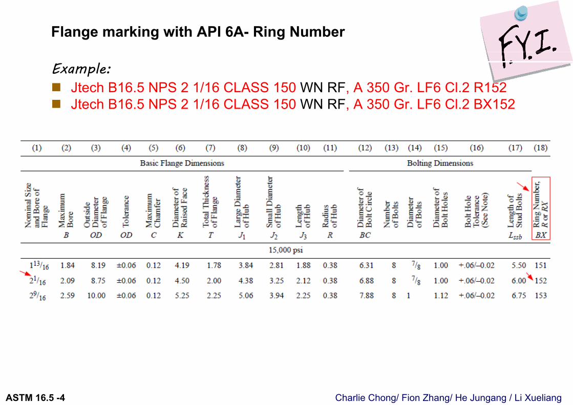
Flange marking with API 6A- Ring Number
Example: Jtech B16.5 NPS 2 1/16 CLASS 150 WN RF, A 350 Gr. LF6 Cl.2 R152 Jtech B16.5 NPS 2 1/16 CLASS 150 WN RF, A 350 Gr. LF6 Cl.2 BX152
Charlie Chong/ Fion Zhang/ He Jungang / Li XueliangASTM 16.5 -4
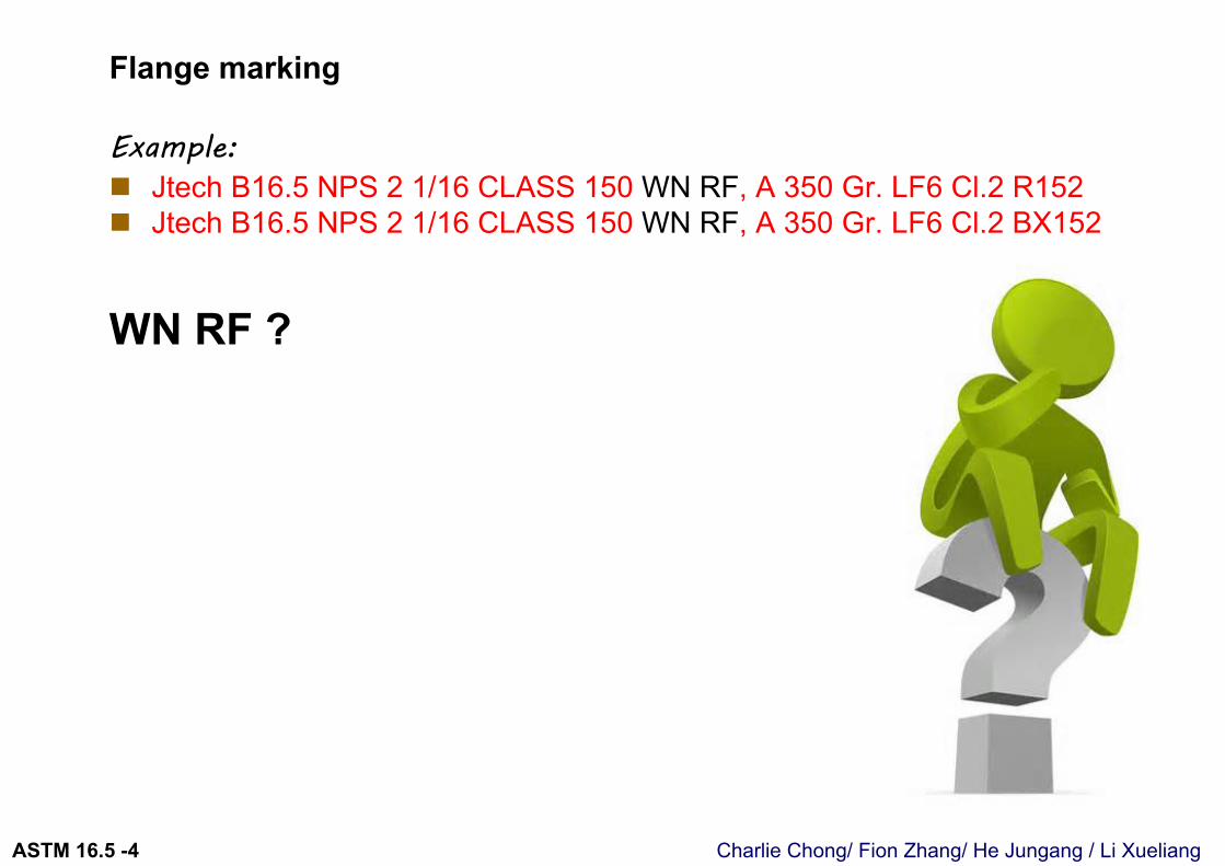
Flange marking
Example: Jtech B16.5 NPS 2 1/16 CLASS 150 WN RF, A 350 Gr. LF6 Cl.2 R152 Jtech B16.5 NPS 2 1/16 CLASS 150 WN RF, A 350 Gr. LF6 Cl.2 BX152
WN RF ?
Charlie Chong/ Fion Zhang/ He Jungang / Li XueliangASTM 16.5 -4
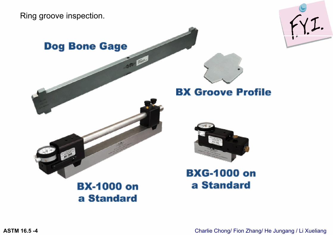
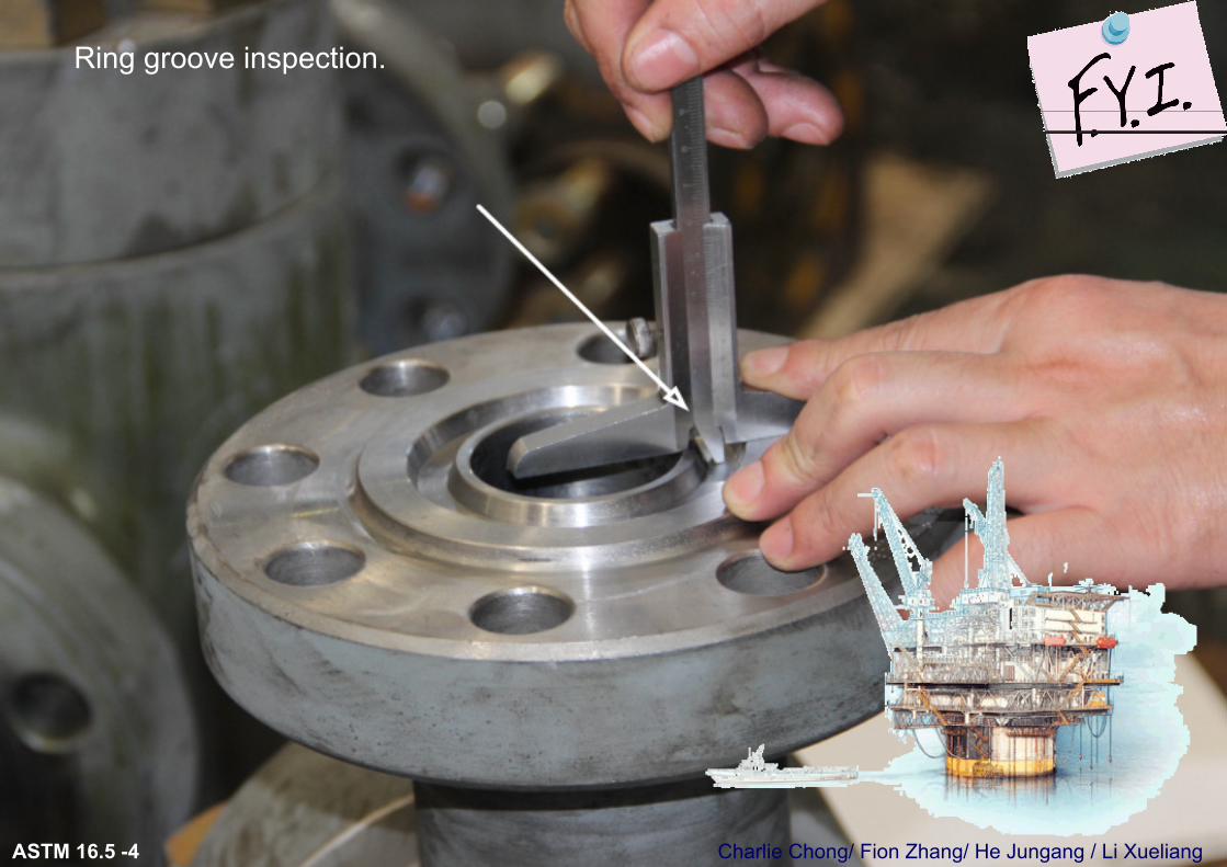
Ring groove inspection.
Charlie Chong/ Fion Zhang/ He Jungang / Li XueliangASTM 16.5 -4
Ring groove inspection.
Charlie Chong/ Fion Zhang/ He Jungang / Li XueliangASTM 16.5 -4
Ring groove inspection.
Charlie Chong/ Fion Zhang/ He Jungang / Li XueliangASTM 16.5 -4
Ring groove inspection.
Charlie Chong/ Fion Zhang/ He Jungang / Li XueliangASTM 16.5 -4
Ring groove inspection.
Charlie Chong/ Fion Zhang/ He Jungang / Li XueliangASTM 16.5 -4
Ring groove inspection.
Charlie Chong/ Fion Zhang/ He Jungang / Li XueliangASTM 16.5 -4
4.2.8 Multiple Material Marking. 多材料标记Material for components that meet the requirements for more than one
specification or grade of a specification listed in Table 1A may, at the manufacturer’s option, be marked with more than one of the applicable specification or grade symbols. These identification markings shall be placed so as to avoid confusion in identification. The multiple marking shall be in accordance with the guidelines set out in ASME Boiler and Pressure Vessel Code, Section II, Part D, Appendix 7.
如法兰/法兰件材料符合一个以上的材料规格, 依生产商的选择, 产品上可以多材料标记.
注意点是确保不会引起混乱. 应与ASME BPVC-II, Part D, Appendix 7 规范中规定的指引执行.
Charlie Chong/ Fion Zhang/ He Jungang / Li XueliangASTM 16.5 -5
5 MATERIALS 材料
Charlie Chong/ Fion Zhang/ He Jungang / Li XueliangASTM 16.5 -5
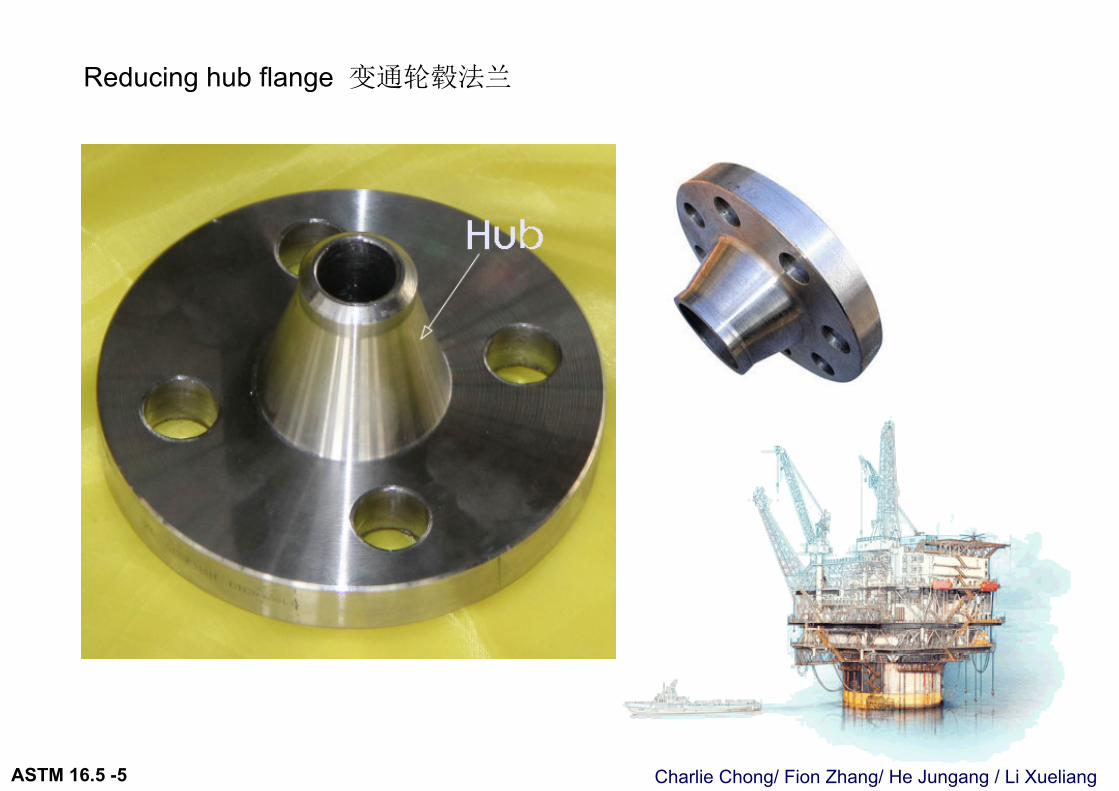
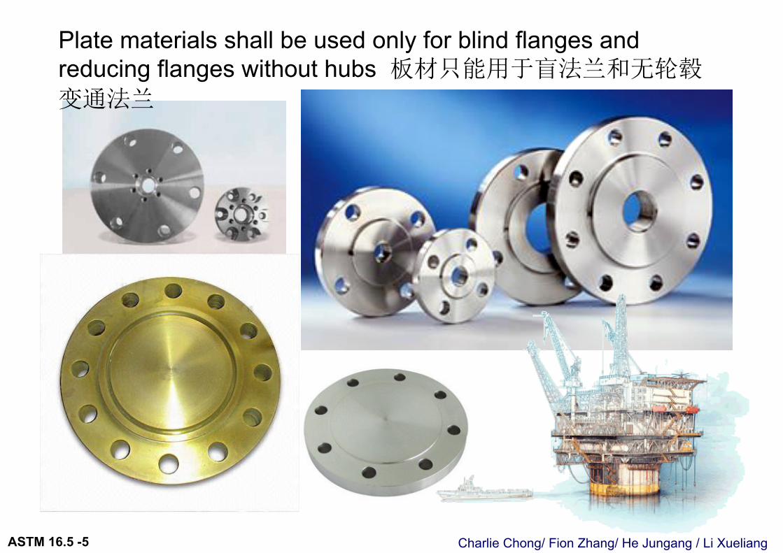
5.1 General 概述Materials required for flanges and flanged fittings are listed in Table 1A with the
restriction that plate materials shall be used only for blind flanges and reducing flanges without hubs. Recommended bolting materials are listed in Table 1B (see para. 5.3).
表1A列举法兰/法兰件材料(板材只能允许用到盲板或变通非轮毂法兰) 表1B列举螺栓材料
Corresponding materials listed in Section II of the ASME Boiler and Pressure Vessel Code may be used provided that the requirements of the ASME specification are identical to or more stringent than the ASTM specification for the Grade, Class, or type of material.
ASME 相应的等同或更高质量的材料是被允许使用的.
Charlie Chong/ Fion Zhang/ He Jungang / Li XueliangASTM 16.5 -5
Reducing hub flange 变通轮毂法兰
Charlie Chong/ Fion Zhang/ He Jungang / Li XueliangASTM 16.5 -5
Plate materials shall be used only for blind flanges and reducing flanges without hubs 板材只能用于盲法兰和无轮毂
变通法兰
Charlie Chong/ Fion Zhang/ He Jungang / Li XueliangASTM 16.5 -5
Socket flange?
Charlie Chong/ Fion Zhang/ He Jungang / Li XueliangASTM 16.5 -5
Charlie Chong/ Fion Zhang/ He Jungang / Li XueliangASTM 16.5 -5
5.1.1 Application. Criteria for the selection of materials are not within the scope of this Standard. The possibility of material deterioration in service should be considered by the user. Carbide phase conversion to graphite and excessive oxidation of ferritic materials, susceptibility to intergranular corrosion of austenitic materials, or grain boundary attack of nickel base alloys are among those items requiring attention. A discussion of precautionary considerations can be found in ASME B31.3, Appendix F; Section II, Part D, Appendix A; and Section III, Division 1, Appendix W of the ASME Boiler and Pressure Vessel Code.
“合适工艺上使用的材料选项不是此规范的范围” – 考试题这里描述了在实际的工作状况, 材料可能遇见的不同损坏机理, 如碳化, 奥氏体不锈钢间晶腐蚀, 铁素体材料过度氧化, 镍基材料晶间选择性侵袭,等等.
一些预防性因素的讨论能在以下规范做为参考:ASME B31.3, Appendix F; Section II, Part D, Appendix A; and Section III, Division 1, Appendix W of the ASME Boiler and Pressure Vessel Code.
Charlie Chong/ Fion Zhang/ He Jungang / Li XueliangASTM 16.5 -5
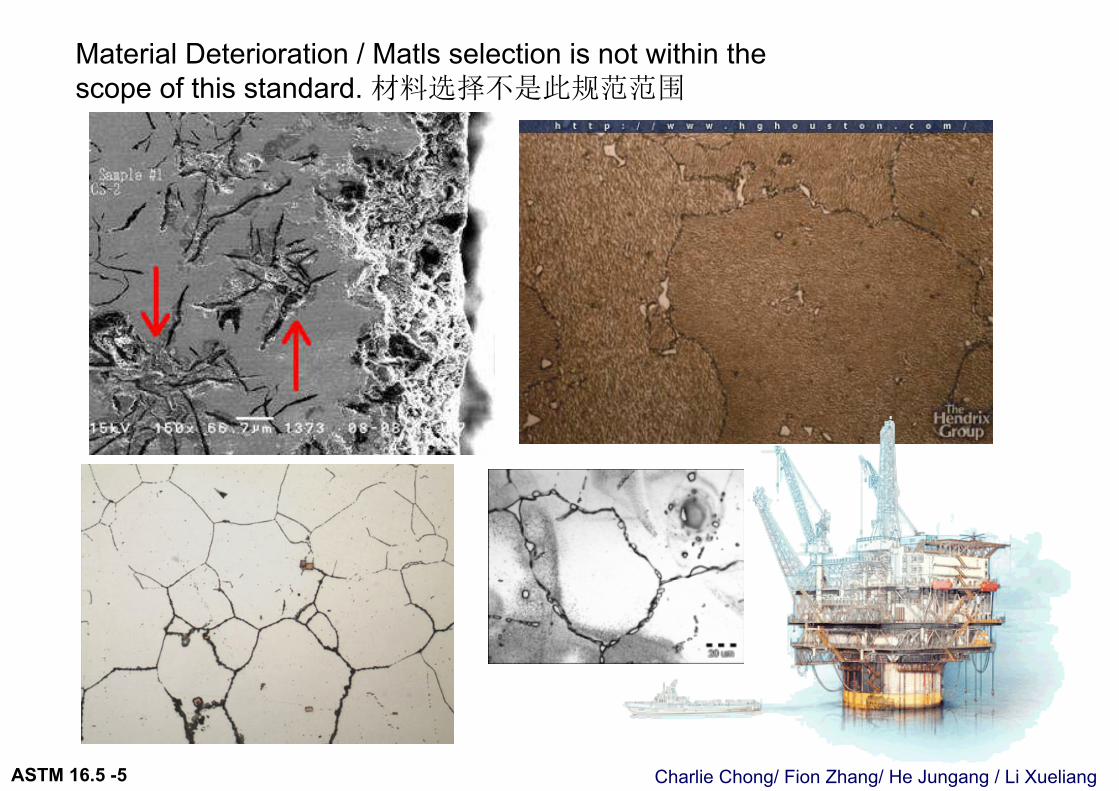
Material Deterioration / Matls selection is not within the scope of this standard. 材料选择不是此规范范围
Charlie Chong/ Fion Zhang/ He Jungang / Li XueliangASTM 16.5 -5
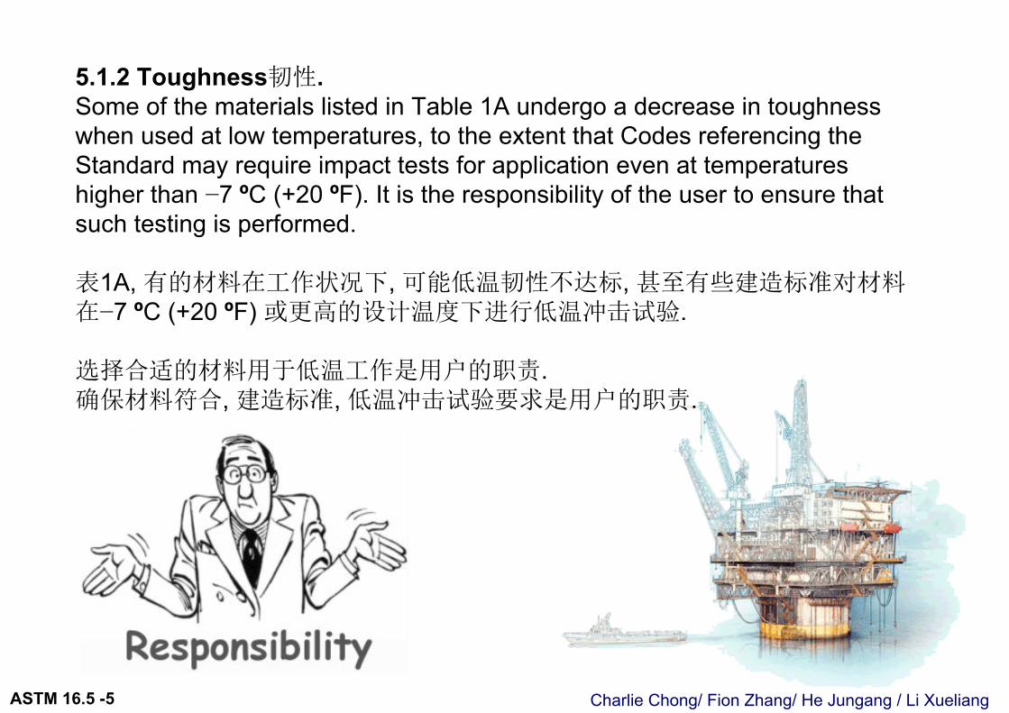
5.1.2 Toughness韧性. Some of the materials listed in Table 1A undergo a decrease in toughness when used at low temperatures, to the extent that Codes referencing the Standard may require impact tests for application even at temperatures higher than −7 ºC (+20 ºF). It is the responsibility of the user to ensure that such testing is performed.
表1A, 有的材料在工作状况下, 可能低温韧性不达标, 甚至有些建造标准对材料在−7 ºC (+20 ºF) 或更高的设计温度下进行低温冲击试验.
选择合适的材料用于低温工作是用户的职责.确保材料符合, 建造标准, 低温冲击试验要求是用户的职责.

Charlie Chong/ Fion Zhang/ He Jungang / Li XueliangASTM 16.5 -5
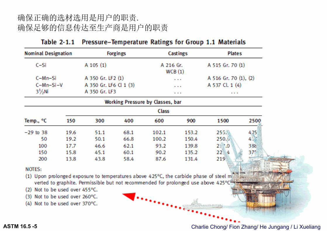
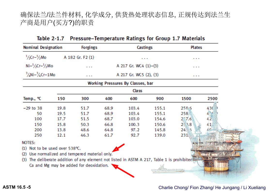
5.1.3 Responsibility 职责. When service conditions dictate the implementation of special material requirements [e.g., using a Group 2 material above 538ºC (1,000ºF)], it is the user’s responsibility to so specify to the manufacturer in order to ensure compliance with metallurgical requirements listed in the notes in Tables 2-1.1 through 2-3.17 (Tables II-2-1.1 through II-2-3.17 of Mandatory Appendix II).
对生产厂家, 声明(合同) 确保材料冶金符合 表2-1.1 ~ 2-3.17 要求是用户的责任
Charlie Chong/ Fion Zhang/ He Jungang / Li XueliangASTM 16.5 -5
确保正确的选材选用是用户的职责.确保足够的信息传达至生产商是用户的职责
Charlie Chong/ Fion Zhang/ He Jungang / Li XueliangASTM 16.5 -5
确保法兰/法兰件材料, 化学成分, 供货热处理状态信息, 正规传达到法兰生产商是用户(买方?)的职责
Charlie Chong/ Fion Zhang/ He Jungang / Li XueliangASTM 16.5 -5
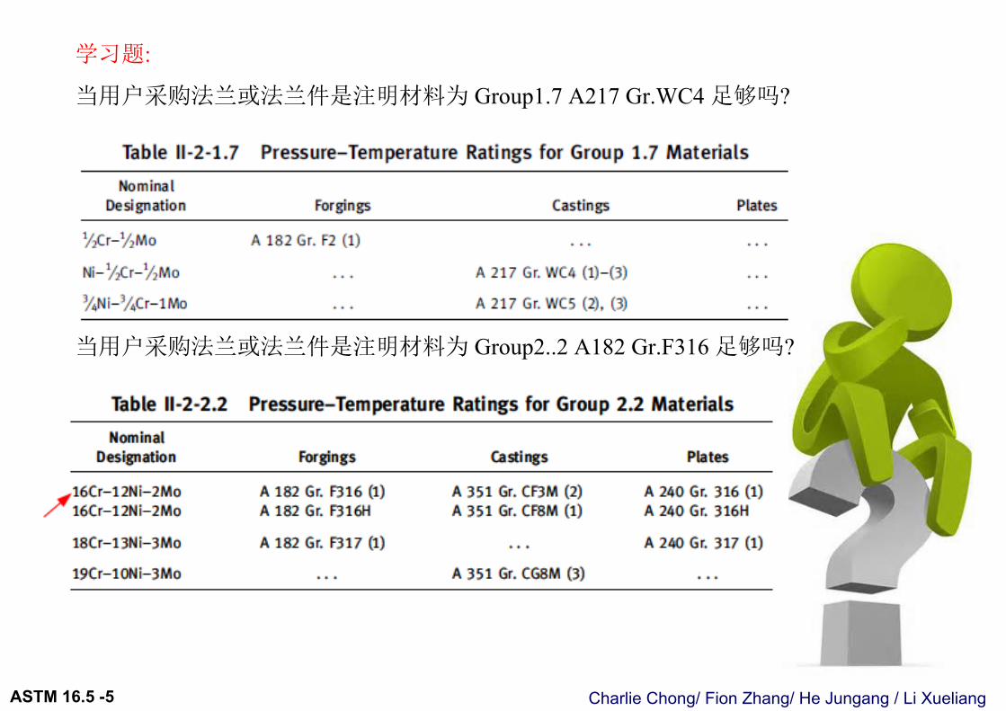
学习题:
当用户采购法兰或法兰件是注明材料为 Group1.7 A217 Gr.WC4 足够吗?
当用户采购法兰或法兰件是注明材料为 Group2..2 A182 Gr.F316 足够吗?
Charlie Chong/ Fion Zhang/ He Jungang / Li XueliangASTM 16.5 -5
Charlie Chong/ Fion Zhang/ He Jungang / Li XueliangASTM 16.5 -5
Charlie Chong/ Fion Zhang/ He Jungang / Li XueliangASTM 16.5 -5
Charlie Chong/ Fion Zhang/ He Jungang / Li XueliangASTM 16.5 -5

Charlie Chong/ Fion Zhang/ He Jungang / Li XueliangASTM 16.5 -5
对生产厂家, 声明(合同) 确保材料冶金符合 表2-1.1 ~ 2-3.17 要求是用户的责任
Charlie Chong/ Fion Zhang/ He Jungang / Li XueliangASTM 16.5 -5
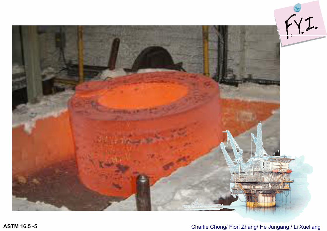
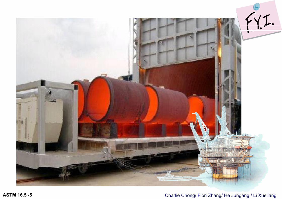
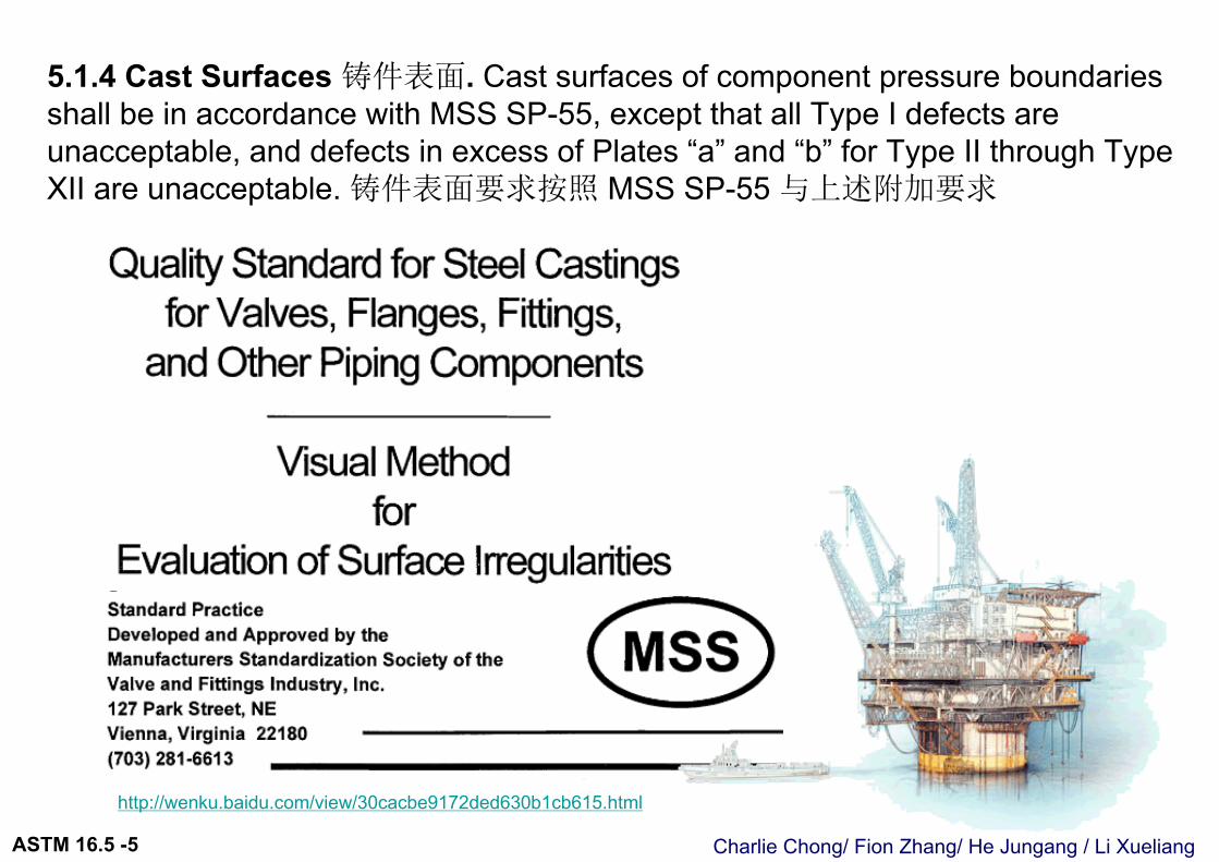
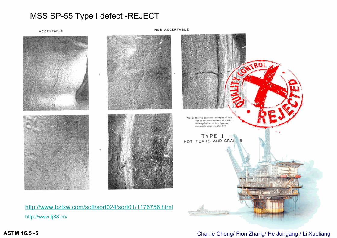
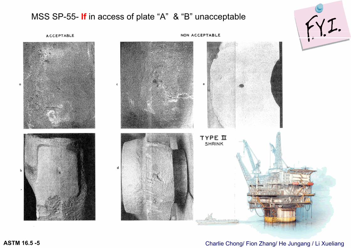
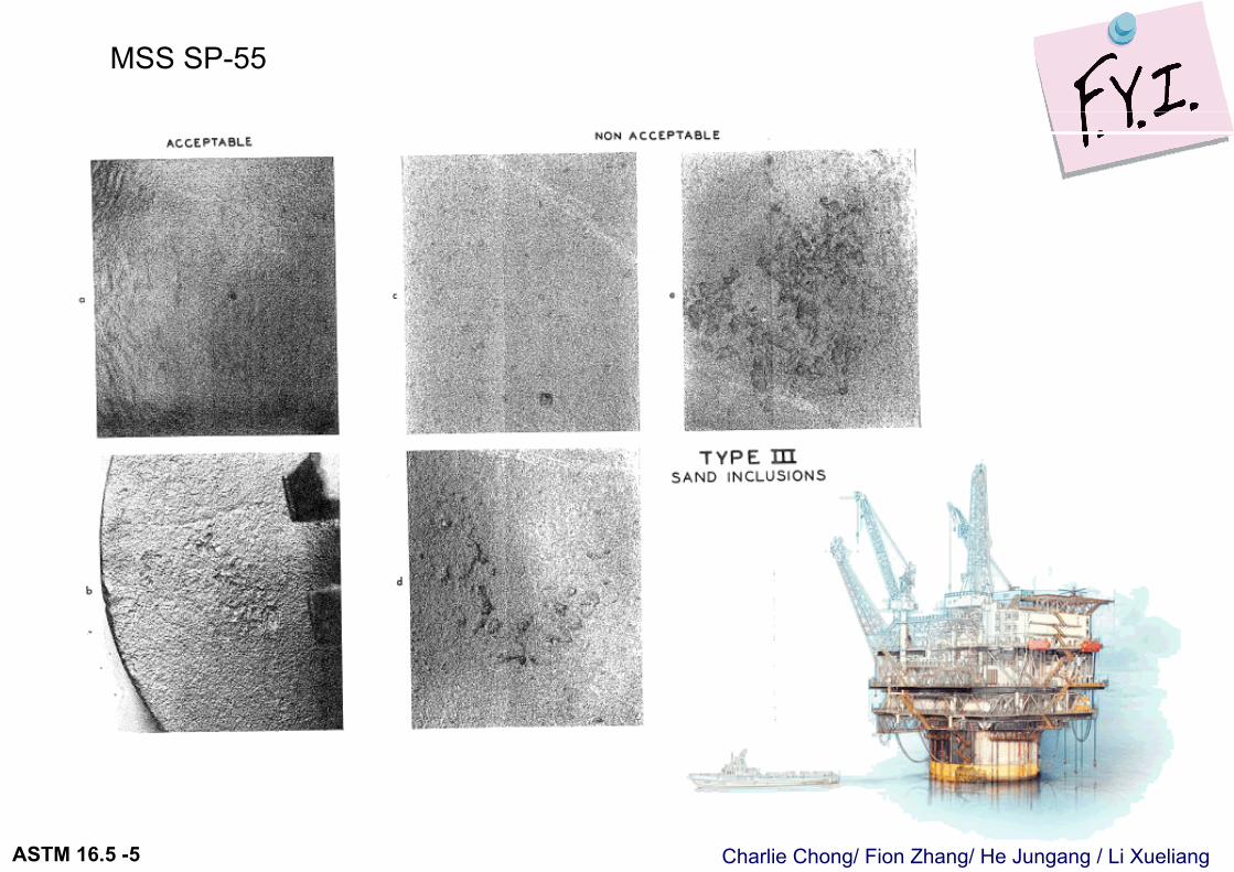
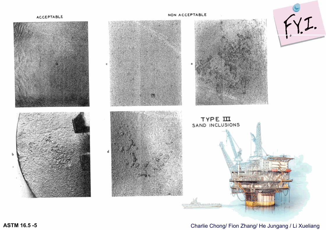
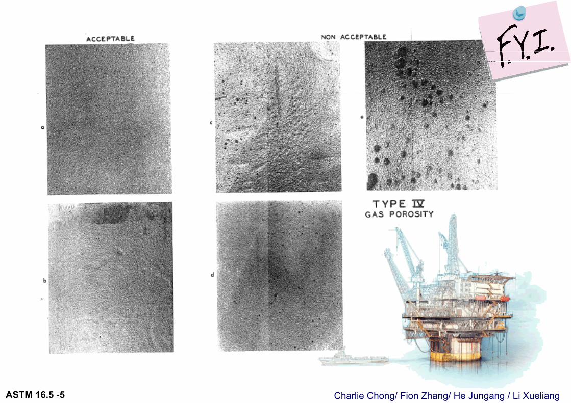
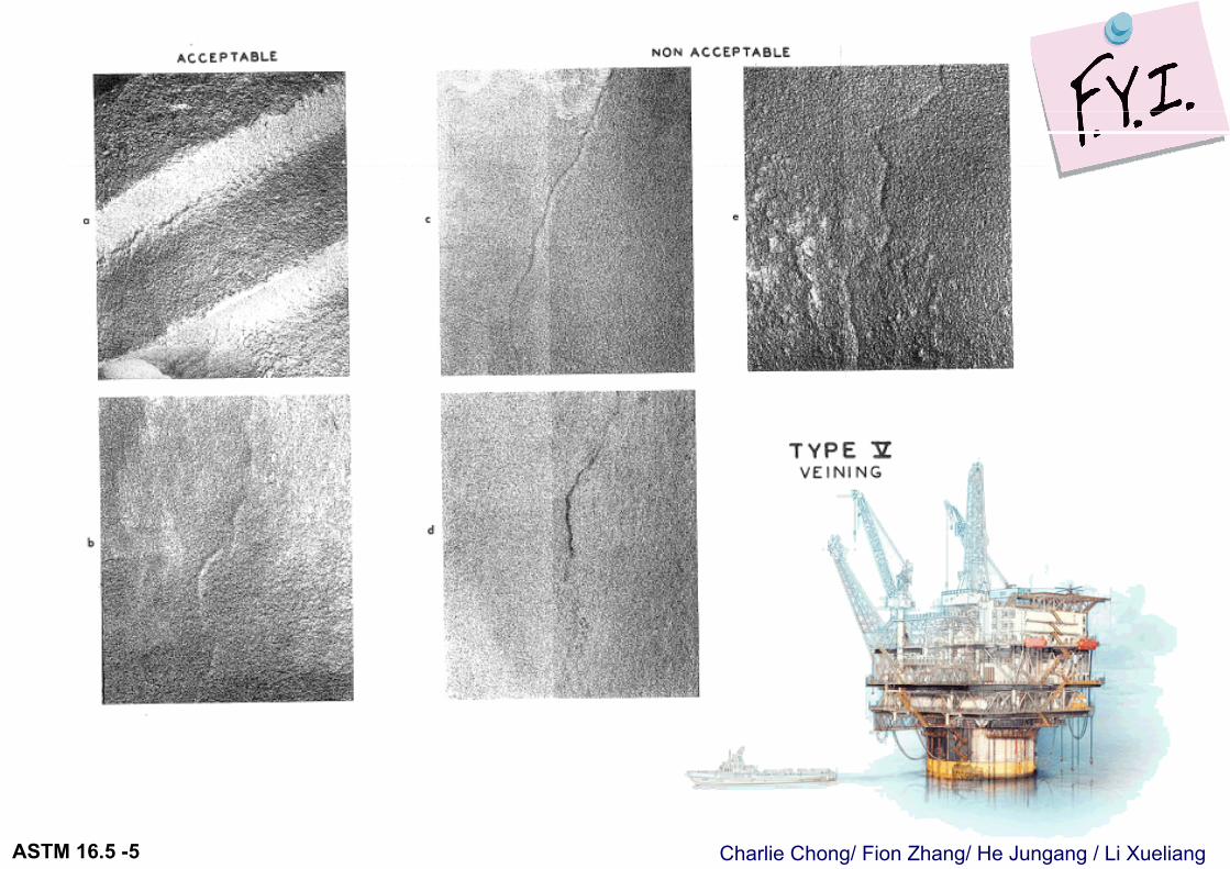
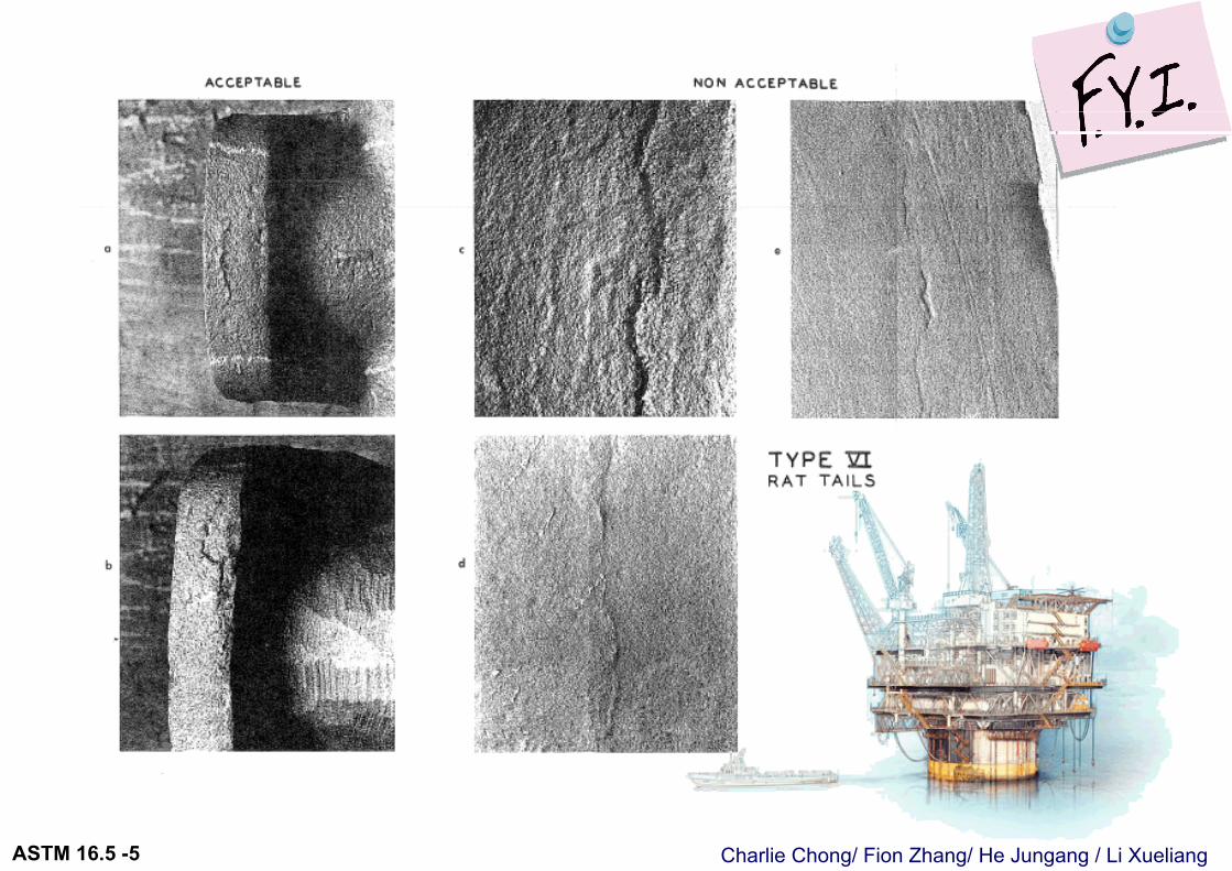
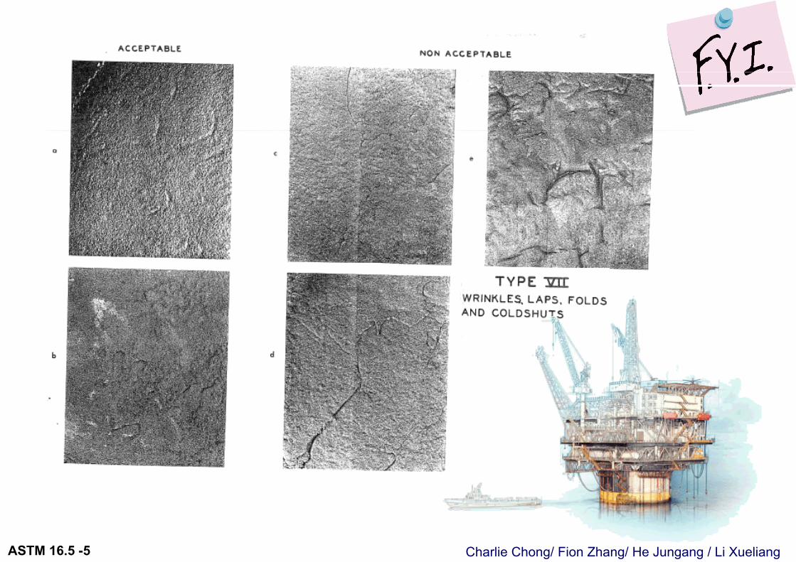
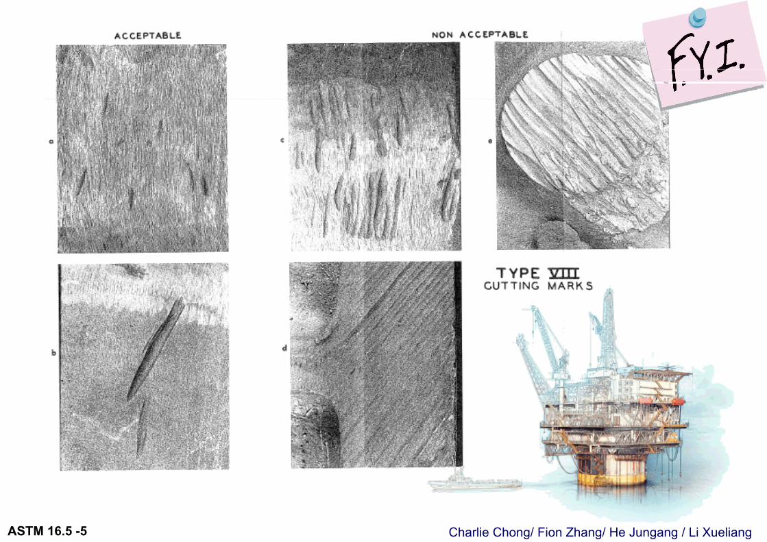
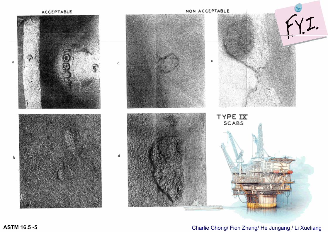
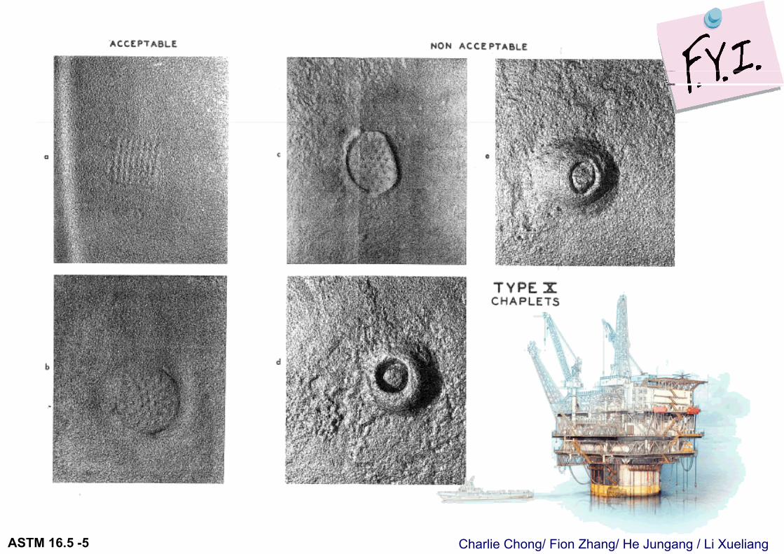
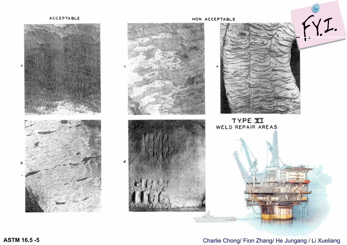
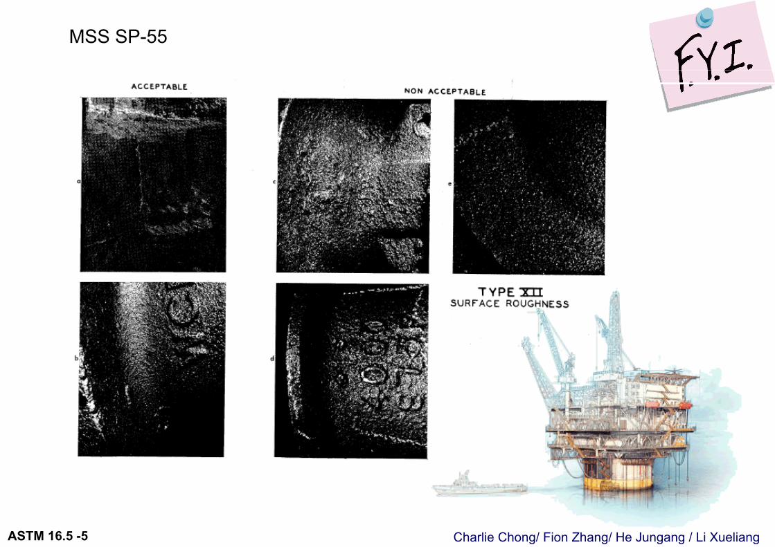
5.1.4 Cast Surfaces 铸件表面. Cast surfaces of component pressure boundaries shall be in accordance with MSS SP-55, except that all Type I defects are unacceptable, and defects in excess of Plates “a” and “b” for Type II through Type XII are unacceptable. 铸件表面要求按照 MSS SP-55 与上述附加要求
http://wenku.baidu.com/view/30cacbe9172ded630b1cb615.html
Charlie Chong/ Fion Zhang/ He Jungang / Li XueliangASTM 16.5 -5
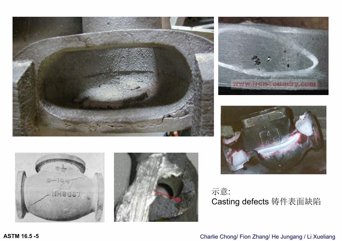
示意: Casting defects 铸件表面缺陷
Charlie Chong/ Fion Zhang/ He Jungang / Li XueliangASTM 16.5 -5
MSS SP-55 Type I defect -REJECT
http://www.bzfxw.com/soft/sort024/sort01/1176756.htmlhttp://www.tj88.cn/
Charlie Chong/ Fion Zhang/ He Jungang / Li XueliangASTM 16.5 -5
MSS SP-55- If in access of plate “A” & “B” unacceptable
Charlie Chong/ Fion Zhang/ He Jungang / Li XueliangASTM 16.5 -5
MSS SP-55
Charlie Chong/ Fion Zhang/ He Jungang / Li XueliangASTM 16.5 -5
Charlie Chong/ Fion Zhang/ He Jungang / Li XueliangASTM 16.5 -5
Charlie Chong/ Fion Zhang/ He Jungang / Li XueliangASTM 16.5 -5
Charlie Chong/ Fion Zhang/ He Jungang / Li XueliangASTM 16.5 -5
Charlie Chong/ Fion Zhang/ He Jungang / Li XueliangASTM 16.5 -5
Charlie Chong/ Fion Zhang/ He Jungang / Li XueliangASTM 16.5 -5
Charlie Chong/ Fion Zhang/ He Jungang / Li XueliangASTM 16.5 -5
Charlie Chong/ Fion Zhang/ He Jungang / Li XueliangASTM 16.5 -5
Charlie Chong/ Fion Zhang/ He Jungang / Li XueliangASTM 16.5 -5
Charlie Chong/ Fion Zhang/ He Jungang / Li XueliangASTM 16.5 -5
MSS SP-55
Charlie Chong/ Fion Zhang/ He Jungang / Li XueliangASTM 16.5 -5
5.2 Mechanical Properties力学性能Mechanical properties shall be obtained from test specimens that represent the final heat-treated condition of the material required by the material specification.
机械性能应与试样应当代表最终热处理条件下得到的材料性能
Charlie Chong/ Fion Zhang/ He Jungang / Li XueliangASTM 16.5 -5
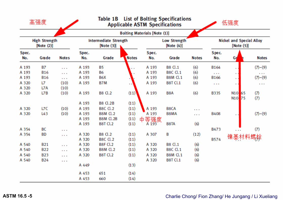
5.3 Bolting 螺栓5.3.1 General. Bolting listed in Table 1B is recommended for use in flanged joints covered by this Standard. Bolting of other material may be used if permitted by the applicable code or government regulation. Bolting materials are subject to the limitations given in paras. 5.3.2 through 5.3.5.螺栓应当按照Table 1B 选材.在设计规范或法定规则允许下,其他材料的螺栓可以使用. 约束性规章,请参考后5.3.2~5.3.5
Charlie Chong/ Fion Zhang/ He Jungang / Li XueliangASTM 16.5 -5
Charlie Chong/ Fion Zhang/ He Jungang / Li XueliangASTM 16.5 -5
Explanation on Table 1B
Table 1B GENERAL NOTES:一般说明
a) Bolting material shall not be used beyond temperature limits specified in the governing code. 螺栓应用, 不能超过设计规范规定的温度范围
b) ASME Boiler and Pressure Vessel Code, Section II materials may also be used, provided the requirements of the ASME specification are identical or more stringent than the corresponding ASTM specification for the Grade, Class, or Type listed. ASME BPVC 第二部分材料也可用, 条件是其规范要求等同或比 Table 1B, ASTM选材规格更加严格.
Charlie Chong/ Fion Zhang/ He Jungang / Li XueliangASTM 16.5 -5
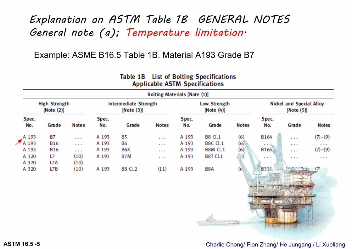
Explanation on ASTM Table 1B GENERAL NOTES General note (a); Temperature limitation.
Example: ASME B16.5 Table 1B. Material A193 Grade B7
Charlie Chong/ Fion Zhang/ He Jungang / Li XueliangASTM 16.5 -5
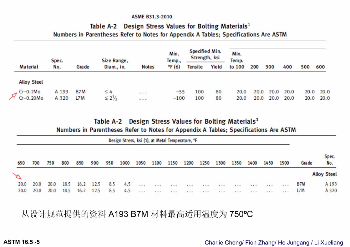
从设计规范提供的资料 A193 B7M 材料最高适用温度为 750ºC
Charlie Chong/ Fion Zhang/ He Jungang / Li XueliangASTM 16.5 -5
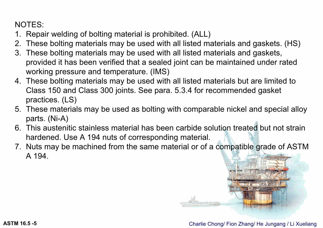
NOTES:1. Repair welding of bolting material is prohibited. (ALL)2. These bolting materials may be used with all listed materials and gaskets. (HS)3. These bolting materials may be used with all listed materials and gaskets,
provided it has been verified that a sealed joint can be maintained under rated working pressure and temperature. (IMS)
4. These bolting materials may be used with all listed materials but are limited to Class 150 and Class 300 joints. See para. 5.3.4 for recommended gasket practices. (LS)
5. These materials may be used as bolting with comparable nickel and special alloy parts. (Ni-A)
6. This austenitic stainless material has been carbide solution treated but not strain hardened. Use A 194 nuts of corresponding material.
7. Nuts may be machined from the same material or of a compatible grade of ASTM A 194.
Charlie Chong/ Fion Zhang/ He Jungang / Li XueliangASTM 16.5 -5
NOTES:6. This austenitic stainless material has been carbide solution treated but not strain
hardened. Use A 194 nuts of corresponding material.7. Nuts may be machined from the same material or of a compatible grade of ASTM
A 194.8. Maximum operating temperature is arbitrarily set at 260ºC (500ºF), unless the
material has been annealed, solution annealed, or hot finished, because hard temper adversely affects design stress in the creep rupture range.
9. Forging quality is not permitted unless the producer last heating or working these parts tests them as required for other permitted conditions in the same specification and certifies their final tensile, yield, and elongation properties to equal or exceed the requirements for one of the other permitted conditions.
10.This ferritic material is intended for low temperature service. Use A 194 Gr. 4 or Gr. 7 nuts.
11.This austenitic stainless material has been carbide solution treated and strain hardened. Use A 194 nuts of corresponding material.
Charlie Chong/ Fion Zhang/ He Jungang / Li XueliangASTM 16.5 -5
12.This carbon steel fastener shall not be used above 200°C (400°F) or below −29°C (−20°F) [see also Note (4)]. Bolts with drilled or undersized heads shall not be used.
13.Acceptable nuts for use with quenched and tempered bolts are A 194 Gr. 2 or Gr. 2H. Mechanical property requirements for studs shall be the same as those for bolts.
14.This special alloy is intended for high-temperature service with austenitic stainless steel.
Charlie Chong/ Fion Zhang/ He Jungang / Li XueliangASTM 16.5 -5
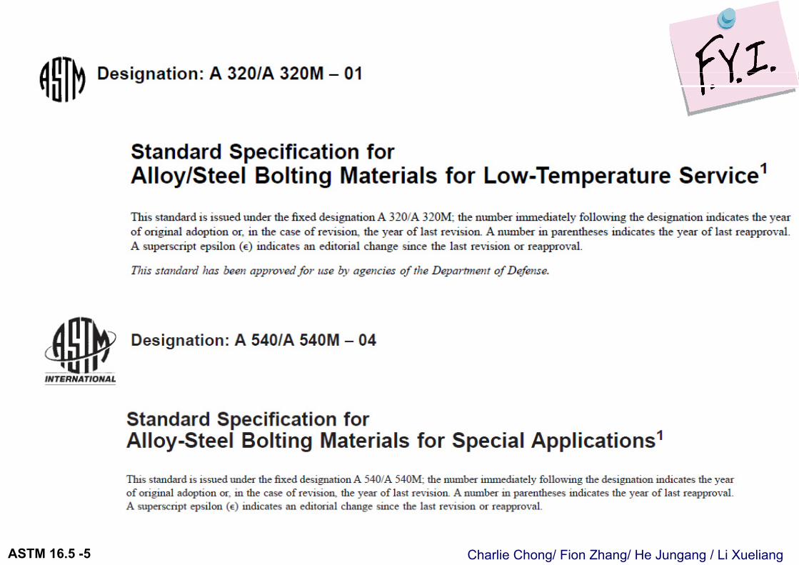
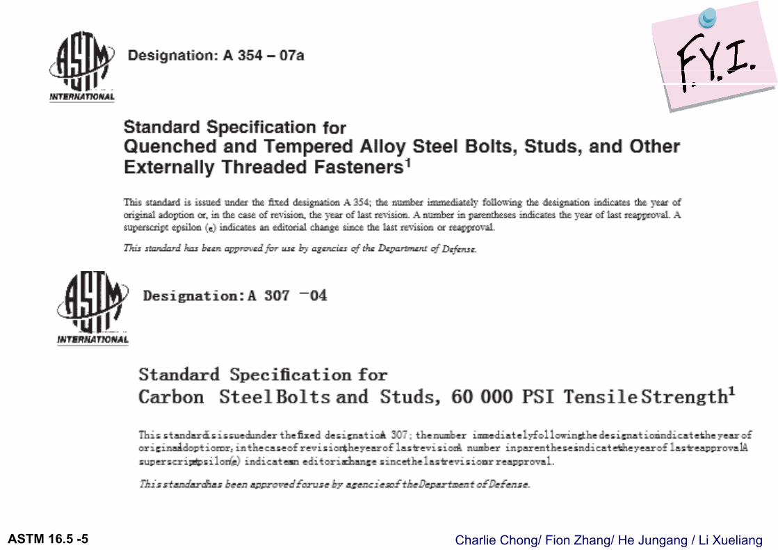
Bolting Material Specifications
Table 1B 提示的规范有;
a) ASTM A193 Alloy-Steel and SS Bolting Materials for High-Temp Serviceb) ASTM A320 Alloy/Steel Bolting Materials for Low-Temperature Servicec) ASTM A540 Alloy-Steel Bolting Materials for Special Applicationsd) ASTM A354 Q&T Alloy Steel Bolts Studs,& Other Externally Threaded Fastenerse) ASTM A307 Carbon Steel Bolts and Studs, 60000PSI Tensile Strength
没有:
ASTM A194 Carbon/Alloy Steel Nuts for Bolts for High Pressure or High Temp Service, or Both
Charlie Chong/ Fion Zhang/ He Jungang / Li XueliangASTM 16.5 -5
Charlie Chong/ Fion Zhang/ He Jungang / Li XueliangASTM 16.5 -5
Charlie Chong/ Fion Zhang/ He Jungang / Li XueliangASTM 16.5 -5
Charlie Chong/ Fion Zhang/ He Jungang / Li XueliangASTM 16.5 -5
Project Material Verification on Bolts & Nuts For information only
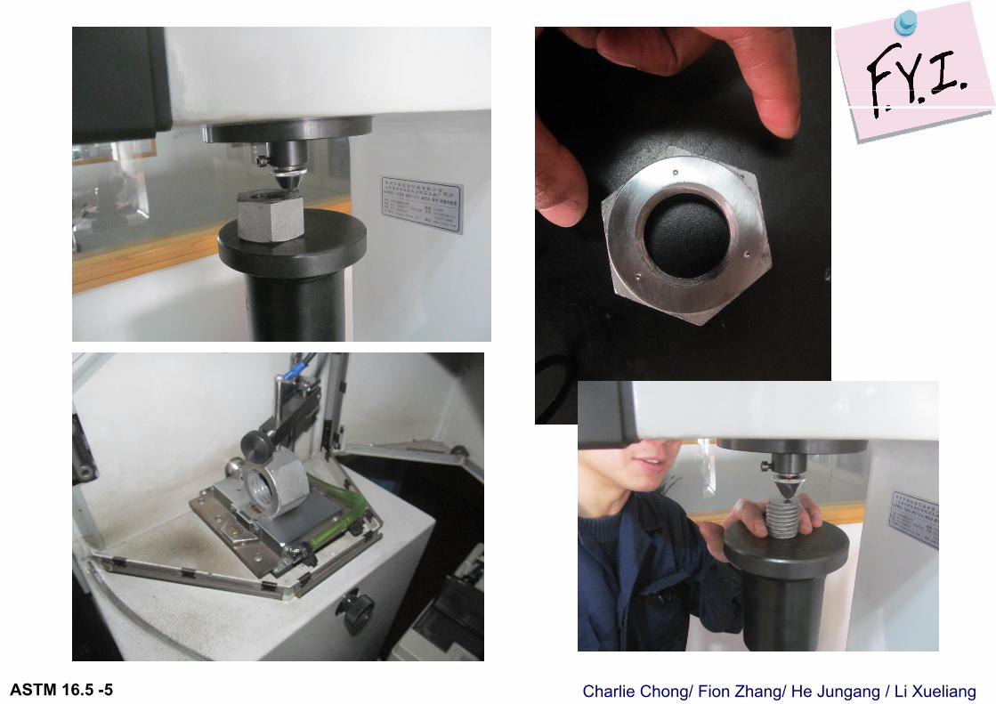
Charlie Chong/ Fion Zhang/ He Jungang / Li XueliangASTM 16.5 -5
Charlie Chong/ Fion Zhang/ He Jungang / Li XueliangASTM 16.5 -5
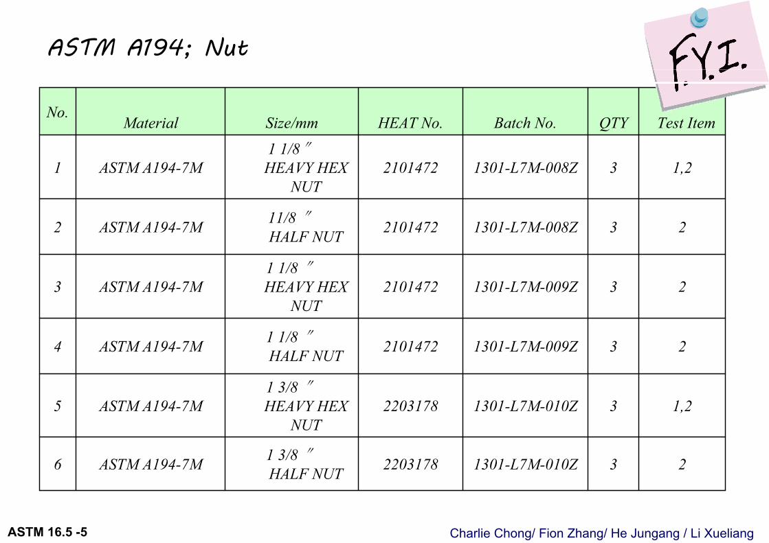
231301-L7M-010Z22031781 3/8 ″HALF NUTASTM A194-7M6
1,231301-L7M-010Z22031781 3/8 ″HEAVY HEX
NUTASTM A194-7M5
231301-L7M-009Z21014721 1/8 ″HALF NUTASTM A194-7M4
231301-L7M-009Z21014721 1/8 ″HEAVY HEX
NUTASTM A194-7M3
231301-L7M-008Z210147211/8 ″HALF NUTASTM A194-7M2
1,231301-L7M-008Z21014721 1/8″HEAVY HEX
NUTASTM A194-7M1
Test ItemQTYBatch No.HEAT No.Size/mmMaterial No.
ASTM A194; Nut
Charlie Chong/ Fion Zhang/ He Jungang / Li XueliangASTM 16.5 -5
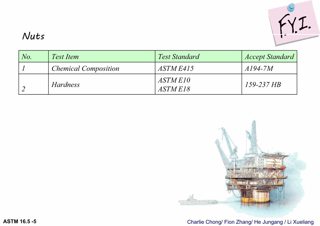
159-237 HBASTM E10 ASTM E18Hardness2
A194-7MASTM E415Chemical Composition 1Accept StandardTest StandardTest ItemNo.
Nuts
Charlie Chong/ Fion Zhang/ He Jungang / Li XueliangASTM 16.5 -5
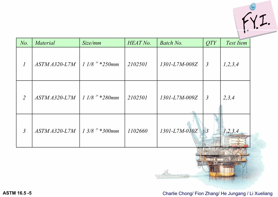
1,2,3,431301-L7M-010Z11026601 3/8″*300mmASTM A320-L7M3
2,3,431301-L7M-009Z21025011 1/8″*280mmASTM A320-L7M2
1,2,3,431301-L7M-008Z21025011 1/8″*250mmASTM A320-L7M1
Test ItemQTYBatch No.HEAT No.Size/mmMaterial No.
Charlie Chong/ Fion Zhang/ He Jungang / Li XueliangASTM 16.5 -5
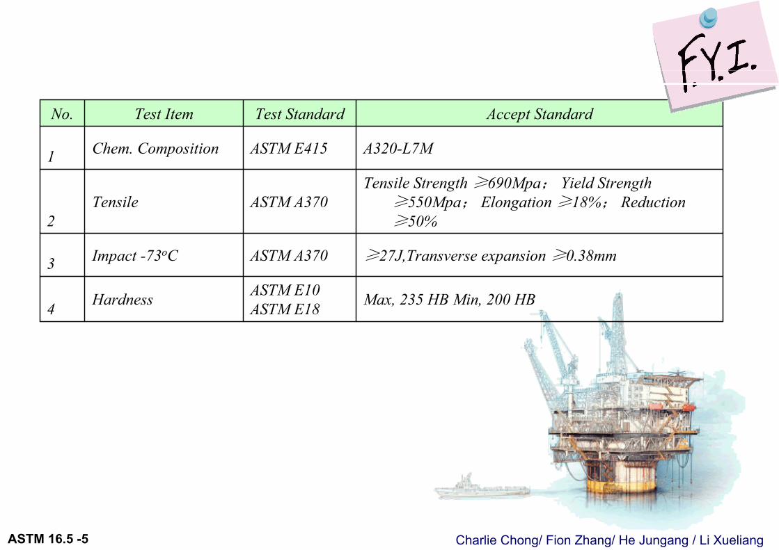
Max, 235 HB Min, 200 HBASTM E10ASTM E18Hardness4
≥27J,Transverse expansion ≥0.38mmASTM A370Impact -73oC3
Tensile Strength ≥690Mpa; Yield Strength ≥550Mpa; Elongation ≥18%; Reduction ≥50%
ASTM A370Tensile 2
A320-L7MASTM E415Chem. Composition 1
Accept StandardTest StandardTest ItemNo.
Charlie Chong/ Fion Zhang/ He Jungang / Li XueliangASTM 16.5 -5
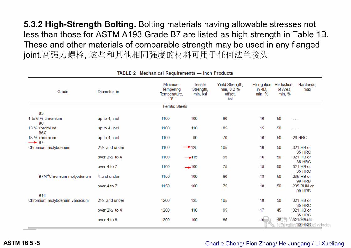
5.3.2 High-Strength Bolting. Bolting materials having allowable stresses not less than those for ASTM A193 Grade B7 are listed as high strength in Table 1B.These and other materials of comparable strength may be used in any flanged joint.高强力螺栓, 这些和其他相同强度的材料可用于任何法兰接头
Charlie Chong/ Fion Zhang/ He Jungang / Li XueliangASTM 16.5 -5
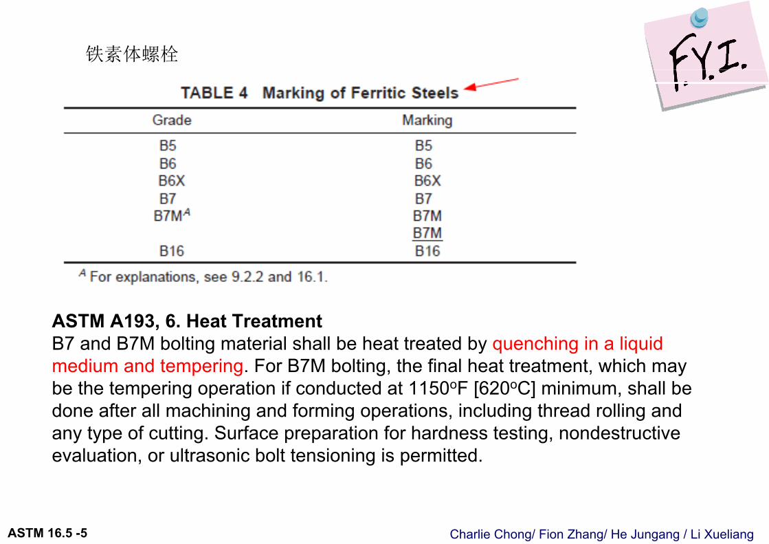
铁素体螺栓
ASTM A193, 6. Heat TreatmentB7 and B7M bolting material shall be heat treated by quenching in a liquid medium and tempering. For B7M bolting, the final heat treatment, which may be the tempering operation if conducted at 1150oF [620oC] minimum, shall be done after all machining and forming operations, including thread rolling and any type of cutting. Surface preparation for hardness testing, nondestructive evaluation, or ultrasonic bolt tensioning is permitted.
Charlie Chong/ Fion Zhang/ He Jungang / Li XueliangASTM 16.5 -5
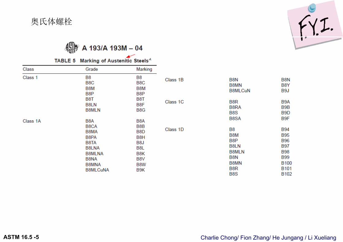
奥氏体螺栓
Charlie Chong/ Fion Zhang/ He Jungang / Li XueliangASTM 16.5 -5
5.3.3 Intermediate Strength Bolting. Bolting materials listed as intermediate strength in Table 1B, and other bolting of comparable strength, may be used inany flanged joint provided the user verifies their ability to seat the selected gasket and maintain a sealed joint under expected operating conditions.
中等强度螺栓能用在任何压力等级的法兰连接, 前提是必须确保能在预期的操作条件下; 合适的入座选定的垫片和保持接头密封.
Charlie Chong/ Fion Zhang/ He Jungang / Li XueliangASTM 16.5 -5
5.3.4 Low-Strength Bolting. 低强度螺栓 Bolting materials having no more than 206 MPa (30 ksi) specifiedminimum yield strength are listed as low strength in Table 1B. These materials and others of comparable strength are to be used only in Class 150 and 300 flanged joints and only with gaskets described in para. 5.4.2. Flanged assemblies using low-strength carbon steel bolts should not be used above 200oC (400oF) or below -29oC (-20oF).
低强度螺栓定义:螺栓材质 SMYS规定的最小屈服强度不大于206 MPa
只能用在压力等级150 / 300接头 本规范; 5.4.2章节描述的法兰垫片. 使用温度限制为 不能高于200oC (400oF) 或低于 -29oC (-20oF).
Charlie Chong/ Fion Zhang/ He Jungang / Li XueliangASTM 16.5 -5
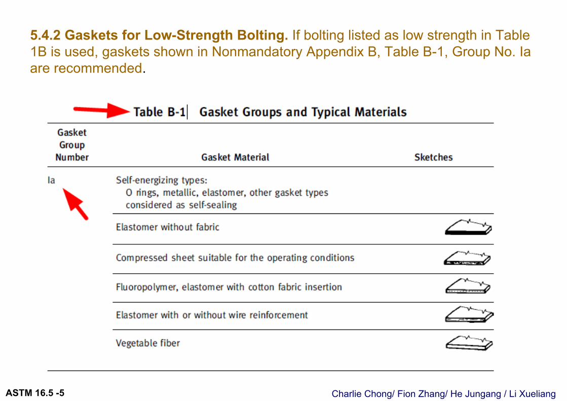
5.4.2 Gaskets for Low-Strength Bolting. If bolting listed as low strength in Table 1B is used, gaskets shown in Nonmandatory Appendix B, Table B-1, Group No. Iaare recommended.
Charlie Chong/ Fion Zhang/ He Jungang / Li XueliangASTM 16.5 -5
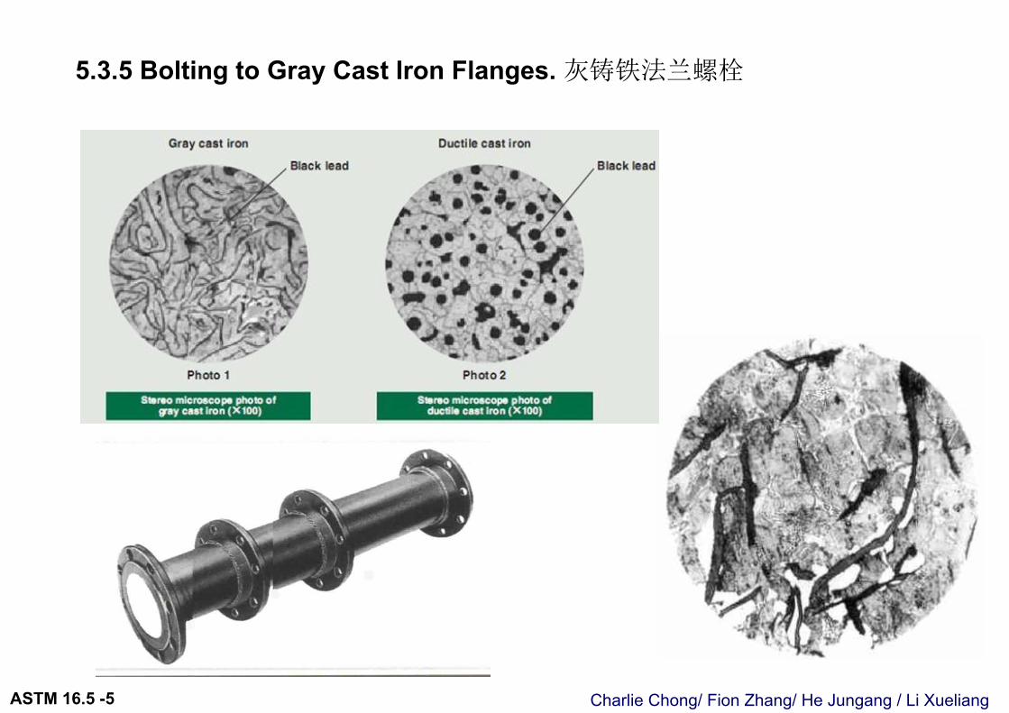
5.3.5 Bolting to Gray Cast Iron Flanges. 灰铸铁法兰螺栓
Charlie Chong/ Fion Zhang/ He Jungang / Li XueliangASTM 16.5 -5
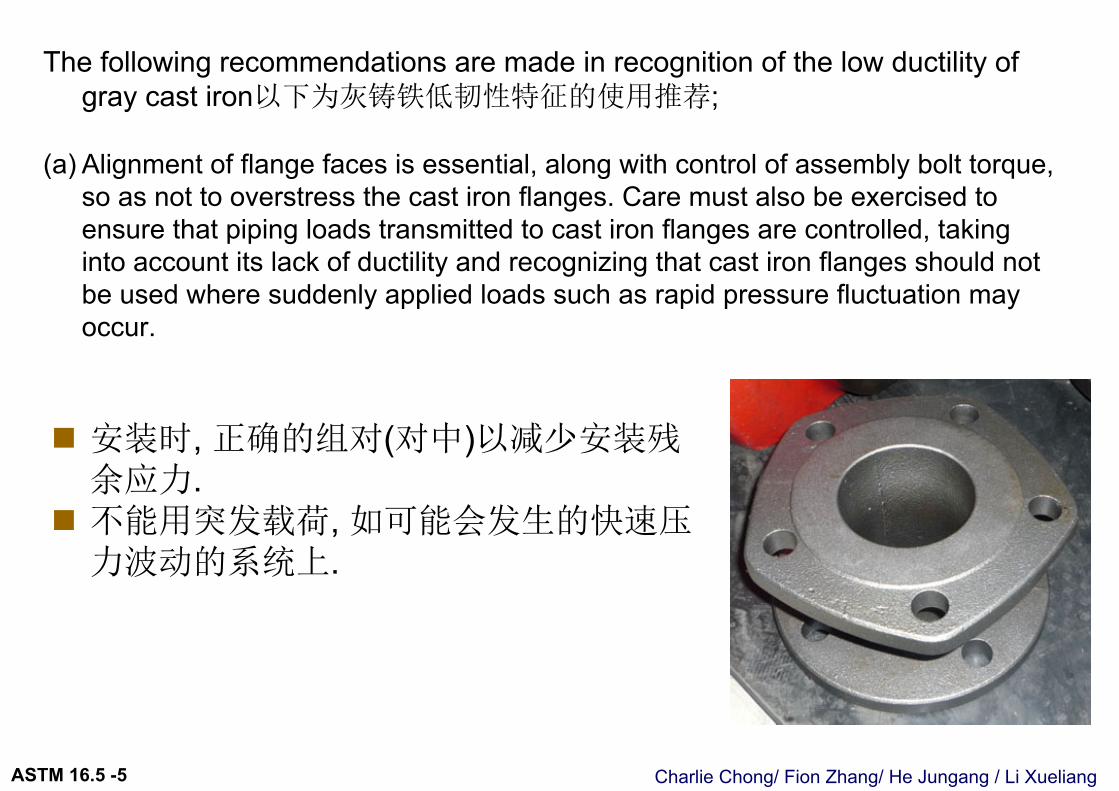
The following recommendations are made in recognition of the low ductility of gray cast iron以下为灰铸铁低韧性特征的使用推荐;
(a) Alignment of flange faces is essential, along with control of assembly bolt torque, so as not to overstress the cast iron flanges. Care must also be exercised to ensure that piping loads transmitted to cast iron flanges are controlled, taking into account its lack of ductility and recognizing that cast iron flanges should not be used where suddenly applied loads such as rapid pressure fluctuation may occur.
安装时, 正确的组对(对中)以减少安装残余应力.
不能用突发载荷, 如可能会发生的快速压力波动的系统上.
Charlie Chong/ Fion Zhang/ He Jungang / Li XueliangASTM 16.5 -5
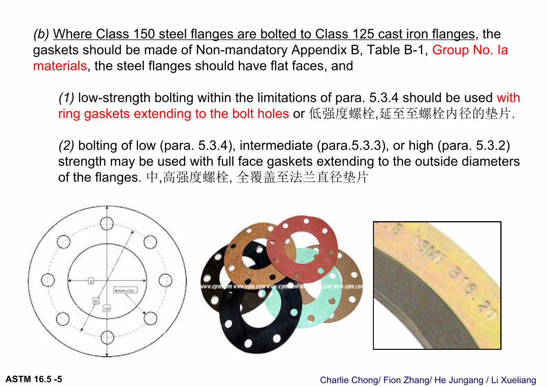
(b) Where Class 150 steel flanges are bolted to Class 125 cast iron flanges, the gaskets should be made of Non-mandatory Appendix B, Table B-1, Group No. Iamaterials, the steel flanges should have flat faces, and
(1) low-strength bolting within the limitations of para. 5.3.4 should be used with ring gaskets extending to the bolt holes or 低强度螺栓,延至至螺栓内径的垫片.
(2) bolting of low (para. 5.3.4), intermediate (para.5.3.3), or high (para. 5.3.2) strength may be used with full face gaskets extending to the outside diameters of the flanges. 中,高强度螺栓, 全覆盖至法兰直径垫片
Charlie Chong/ Fion Zhang/ He Jungang / Li XueliangASTM 16.5 -5
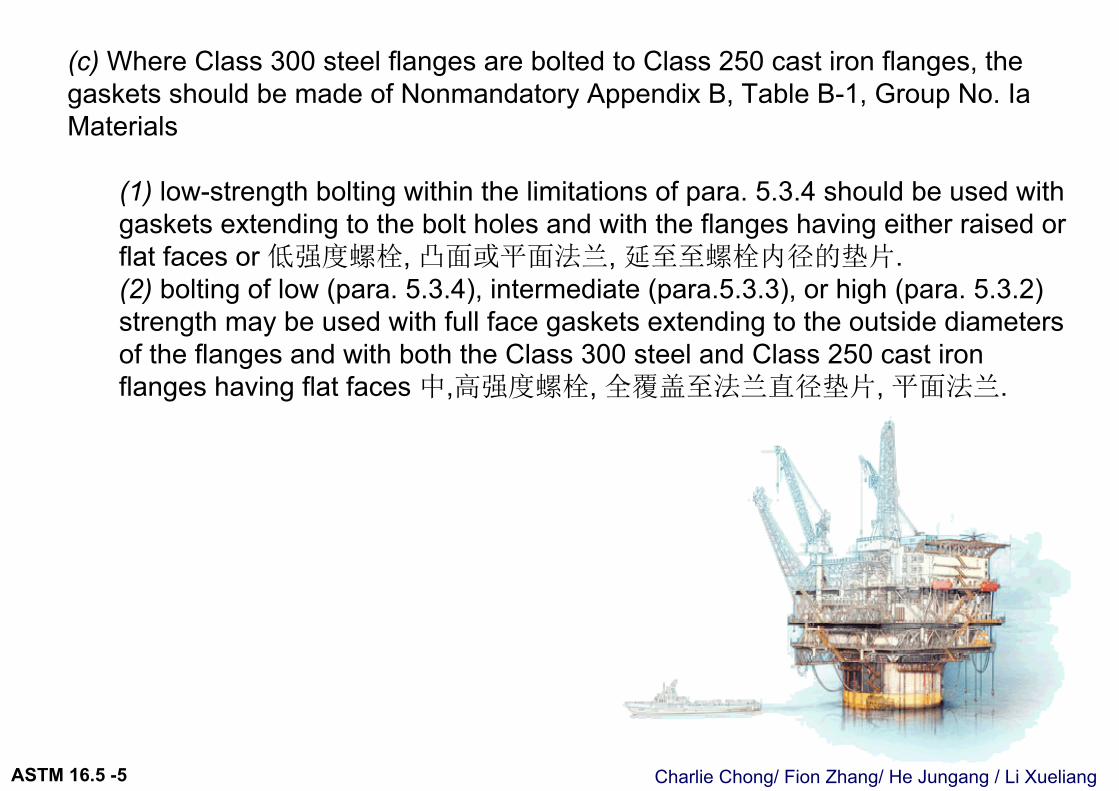
(c) Where Class 300 steel flanges are bolted to Class 250 cast iron flanges, the gaskets should be made of Nonmandatory Appendix B, Table B-1, Group No. IaMaterials
(1) low-strength bolting within the limitations of para. 5.3.4 should be used with gaskets extending to the bolt holes and with the flanges having either raised orflat faces or 低强度螺栓, 凸面或平面法兰, 延至至螺栓内径的垫片.(2) bolting of low (para. 5.3.4), intermediate (para.5.3.3), or high (para. 5.3.2) strength may be used with full face gaskets extending to the outside diameters of the flanges and with both the Class 300 steel and Class 250 cast iron flanges having flat faces 中,高强度螺栓, 全覆盖至法兰直径垫片, 平面法兰.
Charlie Chong/ Fion Zhang/ He Jungang / Li XueliangASTM 16.5 -5
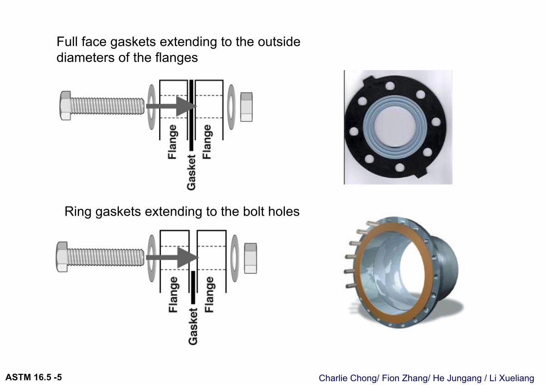
Ring gaskets extending to the bolt holes
Full face gaskets extending to the outside diameters of the flanges
Charlie Chong/ Fion Zhang/ He Jungang / Li XueliangASTM 16.5 -5
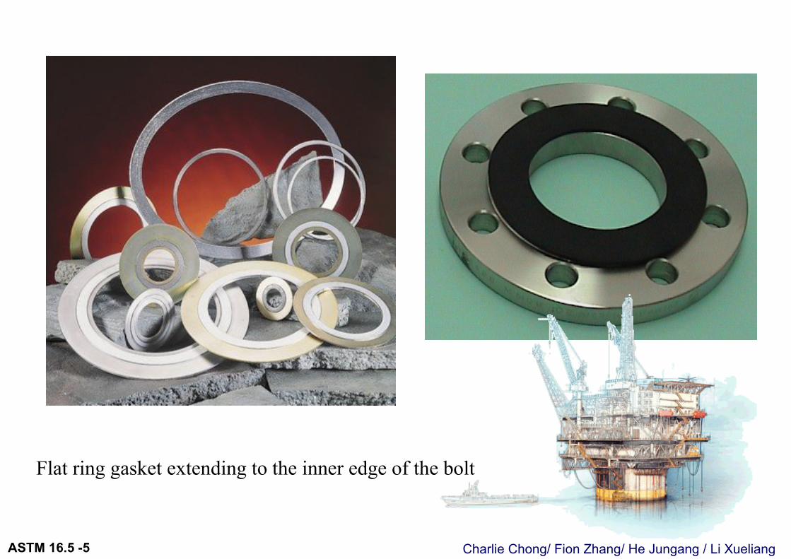
Flat ring gasket extending to the inner edge of the bolt
Charlie Chong/ Fion Zhang/ He Jungang / Li XueliangASTM 16.5 -5
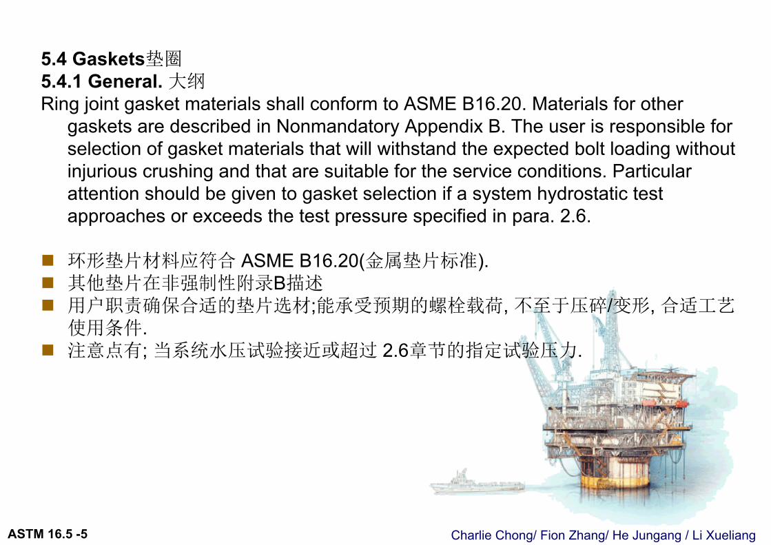
5.4 Gaskets垫圈5.4.1 General. 大纲Ring joint gasket materials shall conform to ASME B16.20. Materials for other
gaskets are described in Nonmandatory Appendix B. The user is responsible for selection of gasket materials that will withstand the expected bolt loading without injurious crushing and that are suitable for the service conditions. Particular attention should be given to gasket selection if a system hydrostatic test approaches or exceeds the test pressure specified in para. 2.6.
环形垫片材料应符合 ASME B16.20(金属垫片标准). 其他垫片在非强制性附录B描述 用户职责确保合适的垫片选材;能承受预期的螺栓载荷, 不至于压碎/变形, 合适工艺
使用条件. 注意点有; 当系统水压试验接近或超过 2.6章节的指定试验压力.
Charlie Chong/ Fion Zhang/ He Jungang / Li XueliangASTM 16.5 -5
Charlie Chong/ Fion Zhang/ He Jungang / Li XueliangASTM 16.5 -5
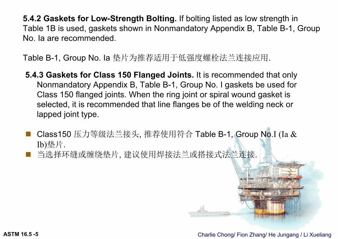
5.4.2 Gaskets for Low-Strength Bolting. If bolting listed as low strength in Table 1B is used, gaskets shown in Nonmandatory Appendix B, Table B-1, Group No. Ia are recommended.
Table B-1, Group No. Ia 垫片为推荐适用于低强度螺栓法兰连接应用.
5.4.3 Gaskets for Class 150 Flanged Joints. It is recommended that only Nonmandatory Appendix B, Table B-1, Group No. I gaskets be used for Class 150 flanged joints. When the ring joint or spiral wound gasket is selected, it is recommended that line flanges be of the welding neck or lapped joint type.
Class150 压力等级法兰接头, 推荐使用符合 Table B-1, Group No.I (Ia & Ib)垫片.
当选择环缝或缠绕垫片, 建议使用焊接法兰或搭接式法兰连接.

Charlie Chong/ Fion Zhang/ He Jungang / Li XueliangASTM 16.5 -5
Charlie Chong/ Fion Zhang/ He Jungang / Li XueliangASTM 16.5 -6
6 DIMENSIONS 尺寸
Charlie Chong/ Fion Zhang/ He Jungang / Li XueliangASTM 16.5 -5
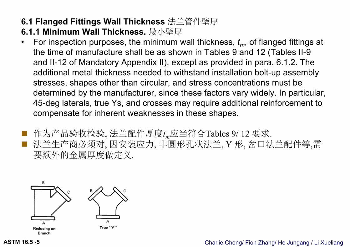
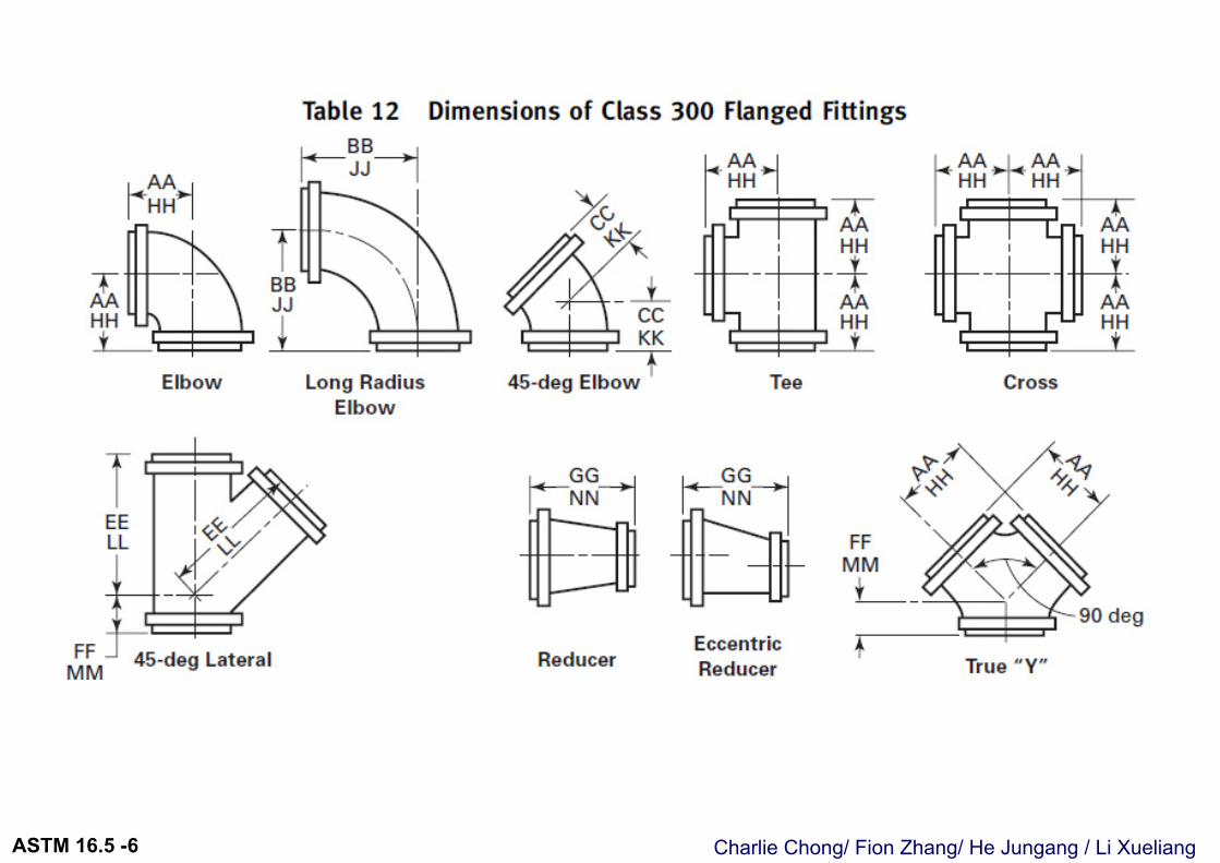
6.1 Flanged Fittings Wall Thickness 法兰管件壁厚6.1.1 Minimum Wall Thickness. 最小壁厚• For inspection purposes, the minimum wall thickness, tm, of flanged fittings at
the time of manufacture shall be as shown in Tables 9 and 12 (Tables II-9 and II-12 of Mandatory Appendix II), except as provided in para. 6.1.2. The additional metal thickness needed to withstand installation bolt-up assembly stresses, shapes other than circular, and stress concentrations must be determined by the manufacturer, since these factors vary widely. In particular, 45-deg laterals, true Ys, and crosses may require additional reinforcement to compensate for inherent weaknesses in these shapes.
作为产品验收检验, 法兰配件厚度tm应当符合Tables 9/ 12 要求. 法兰生产商必须对, 因安装应力, 非圆形孔状法兰, Y 形, 岔口法兰配件等,需
要额外的金属厚度做定义.
Charlie Chong/ Fion Zhang/ He Jungang / Li XueliangASTM 16.5 -6
Charlie Chong/ Fion Zhang/ He Jungang / Li XueliangASTM 16.5 -6
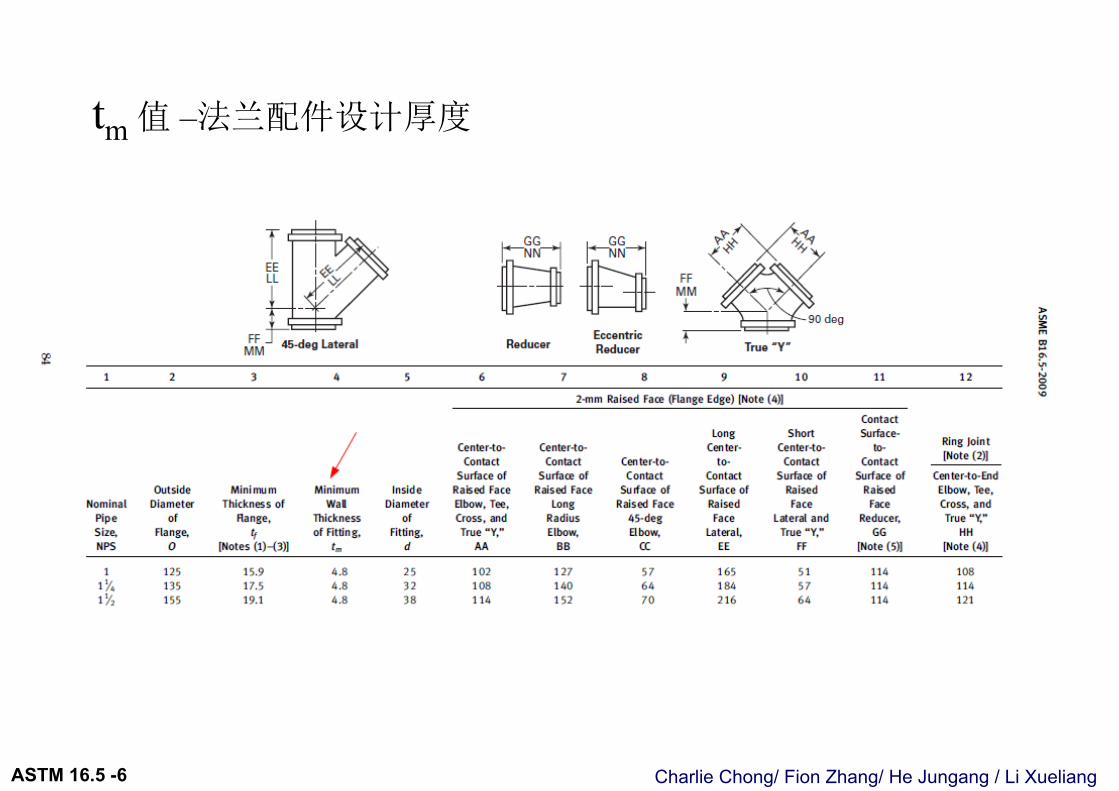
tm 值 –法兰配件设计厚度
Charlie Chong/ Fion Zhang/ He Jungang / Li XueliangASTM 16.5 -6
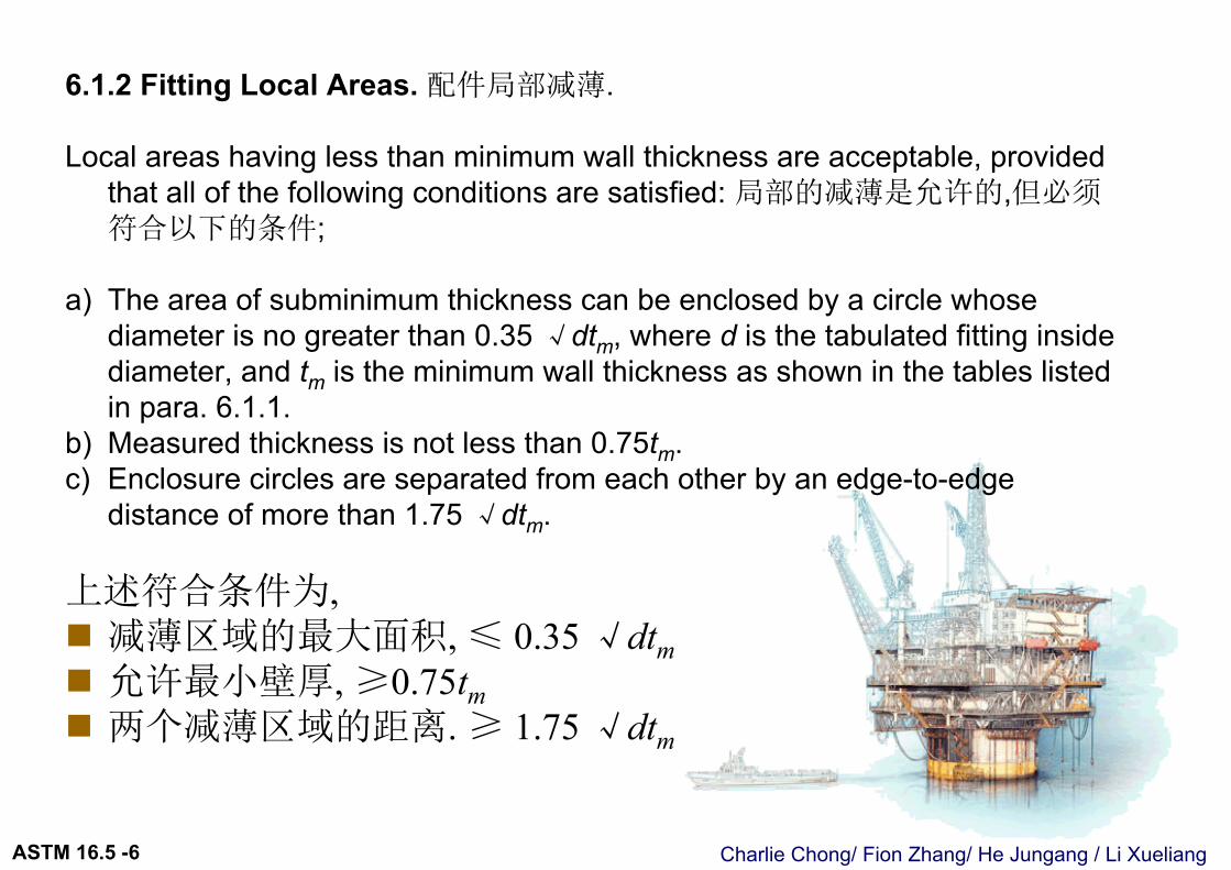
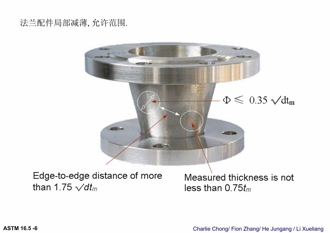
6.1.2 Fitting Local Areas. 配件局部减薄.
Local areas having less than minimum wall thickness are acceptable, provided that all of the following conditions are satisfied: 局部的减薄是允许的,但必须符合以下的条件;
a) The area of subminimum thickness can be enclosed by a circle whose diameter is no greater than 0.35 √dtm, where d is the tabulated fitting inside diameter, and tm is the minimum wall thickness as shown in the tables listed in para. 6.1.1.
b) Measured thickness is not less than 0.75tm.c) Enclosure circles are separated from each other by an edge-to-edge
distance of more than 1.75 √dtm.
上述符合条件为, 减薄区域的最大面积, ≤ 0.35 √dtm 允许最小壁厚, ≥0.75tm 两个减薄区域的距离. ≥ 1.75 √dtm
Charlie Chong/ Fion Zhang/ He Jungang / Li XueliangASTM 16.5 -6
法兰配件局部减薄, 允许范围.
Charlie Chong/ Fion Zhang/ He Jungang / Li XueliangASTM 16.5 -6
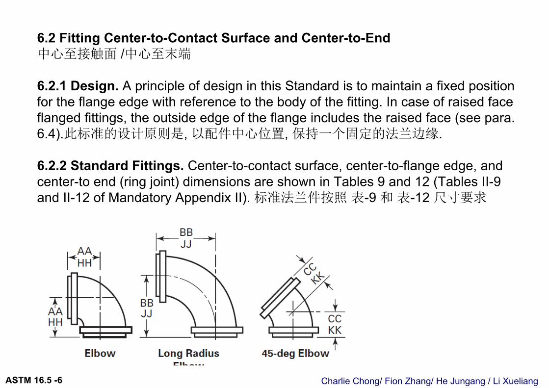
6.2 Fitting Center-to-Contact Surface and Center-to-End中心至接触面 /中心至末端
6.2.1 Design. A principle of design in this Standard is to maintain a fixed position for the flange edge with reference to the body of the fitting. In case of raised faceflanged fittings, the outside edge of the flange includes the raised face (see para. 6.4).此标准的设计原则是, 以配件中心位置, 保持一个固定的法兰边缘.
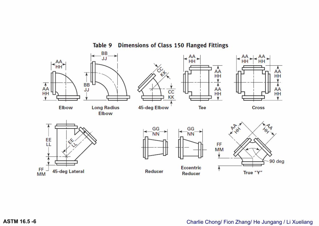
6.2.2 Standard Fittings. Center-to-contact surface, center-to-flange edge, and center-to end (ring joint) dimensions are shown in Tables 9 and 12 (Tables II-9and II-12 of Mandatory Appendix II). 标准法兰件按照 表-9 和 表-12 尺寸要求
Charlie Chong/ Fion Zhang/ He Jungang / Li XueliangASTM 16.5 -6
Charlie Chong/ Fion Zhang/ He Jungang / Li XueliangASTM 16.5 -6
Charlie Chong/ Fion Zhang/ He Jungang / Li XueliangASTM 16.5 -6
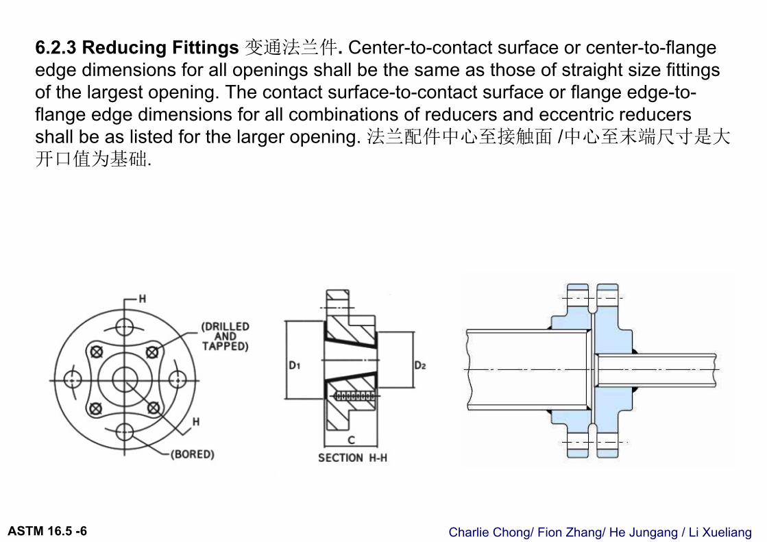
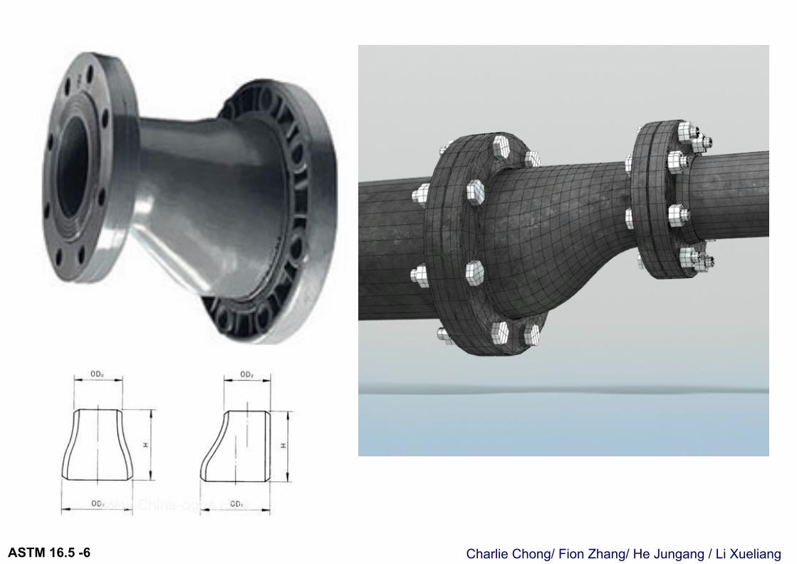
6.2.3 Reducing Fittings 变通法兰件. Center-to-contact surface or center-to-flange edge dimensions for all openings shall be the same as those of straight size fittings of the largest opening. The contact surface-to-contact surface or flange edge-to-flange edge dimensions for all combinations of reducers and eccentric reducers shall be as listed for the larger opening. 法兰配件中心至接触面 /中心至末端尺寸是大开口值为基础.
Charlie Chong/ Fion Zhang/ He Jungang / Li XueliangASTM 16.5 -6
Charlie Chong/ Fion Zhang/ He Jungang / Li XueliangASTM 16.5 -6
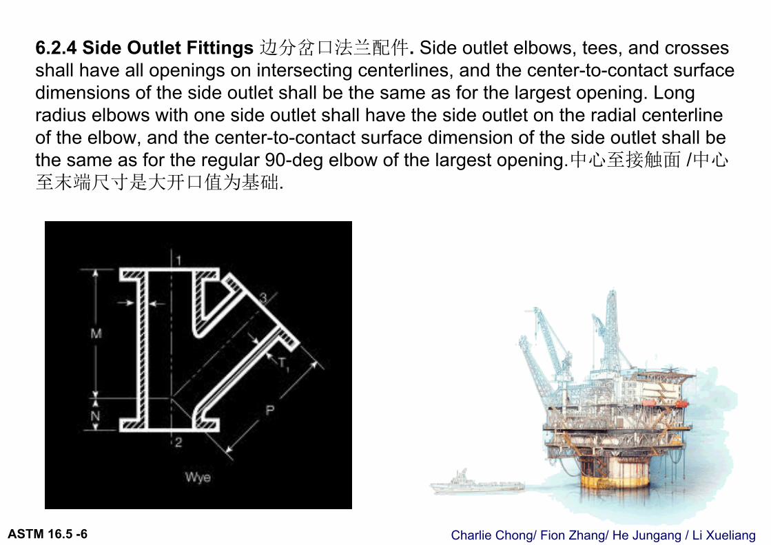
6.2.4 Side Outlet Fittings 边分岔口法兰配件. Side outlet elbows, tees, and crosses shall have all openings on intersecting centerlines, and the center-to-contact surface dimensions of the side outlet shall be the same as for the largest opening. Long radius elbows with one side outlet shall have the side outlet on the radial centerline of the elbow, and the center-to-contact surface dimension of the side outlet shall be the same as for the regular 90-deg elbow of the largest opening.中心至接触面 /中心至末端尺寸是大开口值为基础.
Charlie Chong/ Fion Zhang/ He Jungang / Li XueliangASTM 16.5 -6
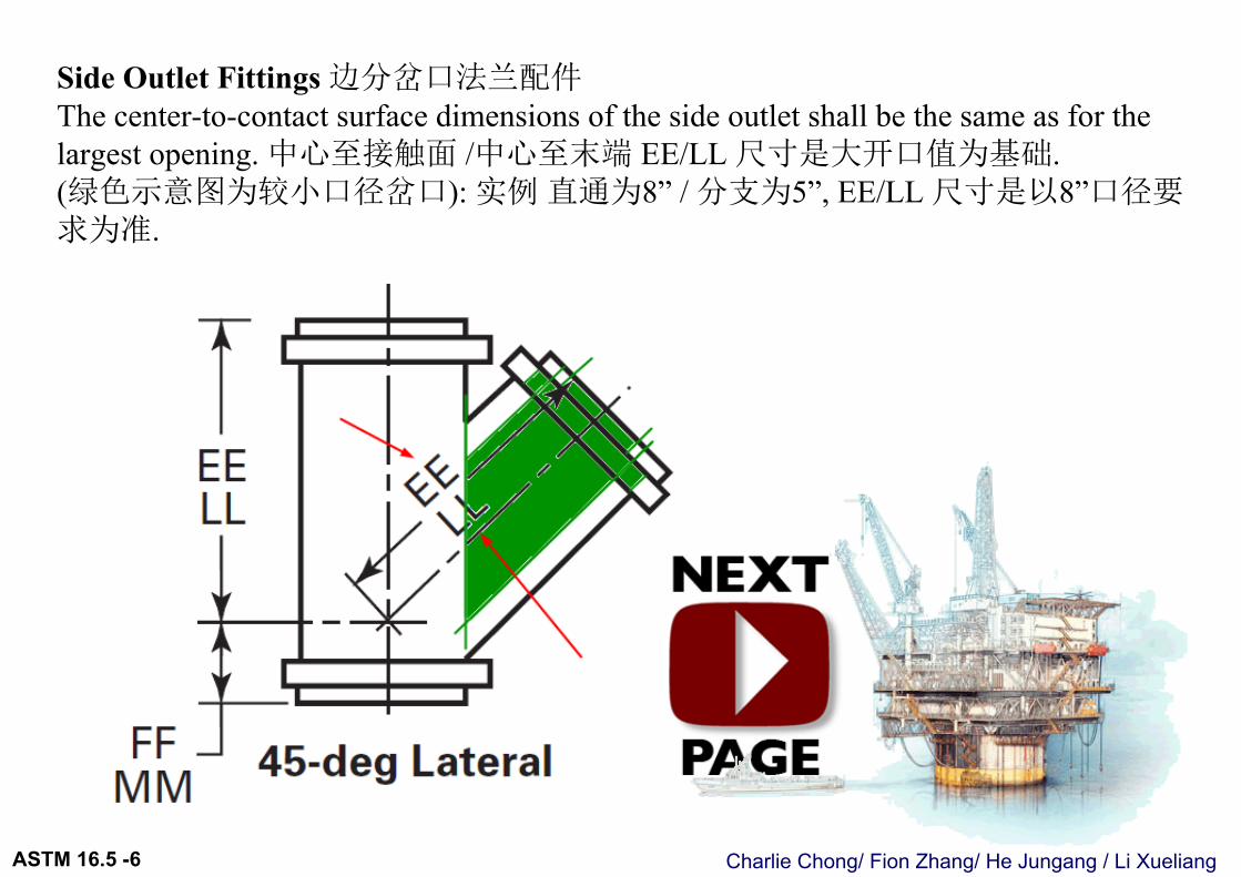
Side Outlet Fittings 边分岔口法兰配件The center-to-contact surface dimensions of the side outlet shall be the same as for the largest opening. 中心至接触面 /中心至末端 EE/LL 尺寸是大开口值为基础.(绿色示意图为较小口径岔口): 实例直通为8” / 分支为5”, EE/LL 尺寸是以8”口径要求为准.
Charlie Chong/ Fion Zhang/ He Jungang / Li XueliangASTM 16.5 -6
Charlie Chong/ Fion Zhang/ He Jungang / Li XueliangASTM 16.5 -6
6.2.5 Special Degree Elbows 特殊角度法兰配件. Special degree elbows ranging from 1 deg to 45 deg, inclusive, shall have the same center-to-contact surface dimensions as 45-deg elbows, and those over 45 deg and up to 90 deg, inclusive, shall have the same center-to-contact surface dimensions as 90-deg elbows. The angle designation of an elbow is its deflection from straight line flow and is also the angle between the flange faces. 从1o至45o 弯头法兰件, 法兰配件尺寸是以45o弯头法兰件值为基础.从>45o至90o 弯头法兰件法, 兰配件尺寸是以90o弯头法兰件值为基础.
Charlie Chong/ Fion Zhang/ He Jungang / Li XueliangASTM 16.5 -6
从1o至45o 弯头法兰件, 法兰配件尺寸是以45o弯头法兰件值为基础.从>45o至90o 弯头法兰件法, 兰配件尺寸是以90o弯头法兰件值为基础.
Charlie Chong/ Fion Zhang/ He Jungang / Li XueliangASTM 16.5 -6
从1o至45o 弯头法兰件, 法兰配件尺寸是以45o弯头法兰件值为基础
Charlie Chong/ Fion Zhang/ He Jungang / Li XueliangASTM 16.5 -6
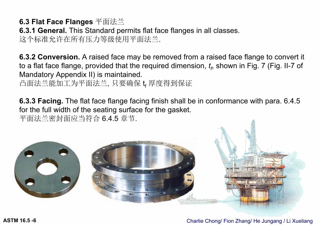
6.3 Flat Face Flanges 平面法兰6.3.1 General. This Standard permits flat face flanges in all classes.这个标准允许在所有压力等级使用平面法兰.
6.3.2 Conversion. A raised face may be removed from a raised face flange to convert it to a flat face flange, provided that the required dimension, tf, shown in Fig. 7 (Fig. II-7 of Mandatory Appendix II) is maintained.凸面法兰能加工为平面法兰, 只要确保 tf 厚度得到保证
6.3.3 Facing. The flat face flange facing finish shall be in conformance with para. 6.4.5 for the full width of the seating surface for the gasket.平面法兰密封面应当符合 6.4.5 章节.
Charlie Chong/ Fion Zhang/ He Jungang / Li XueliangASTM 16.5 -6
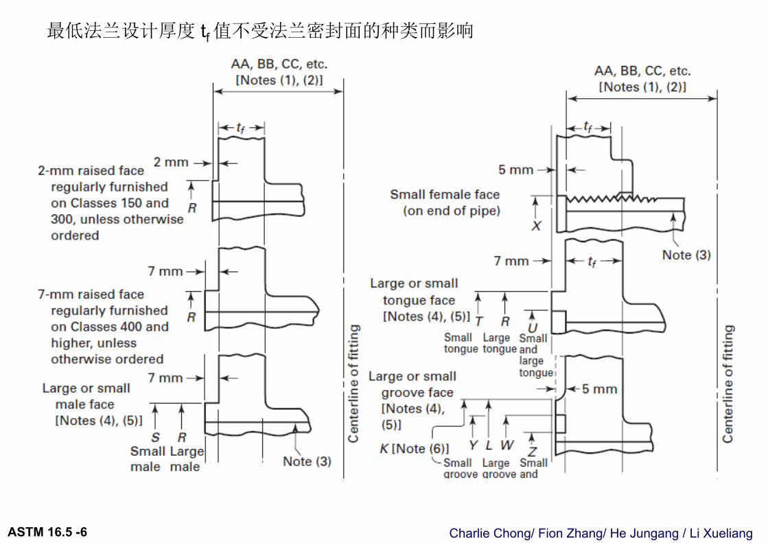
6.4 Flange Facings 法兰密封面6.4.1 General 大纲. Figure 7 (Fig. II-7 of Mandatory Appendix II) shows
dimensional relationships for various flange types and pipe lap facings to be used with lap joints. Table 4 (Table II-4 of Mandatory Appendix II) lists dimensions for facings other than ring joint. Table 5 (Table II-5 of Mandatory Appendix II) lists dimensions for ring joint facings. Classes 150 and 300 pipe flanges and companion flanges of fittings are regularly furnished with 2 mm (0.06 in.) raised face, which is in addition to the minimum flange thickness, tf. Classes 400, 600, 900, 1500, and 2500 pipe flanges and companion flanges of fittings are regularly furnished with 7 mm (0.25 in.) raised face, which is in addition to the minimum flange thickness, tf. (考试题)
Charlie Chong/ Fion Zhang/ He Jungang / Li XueliangASTM 16.5 -6
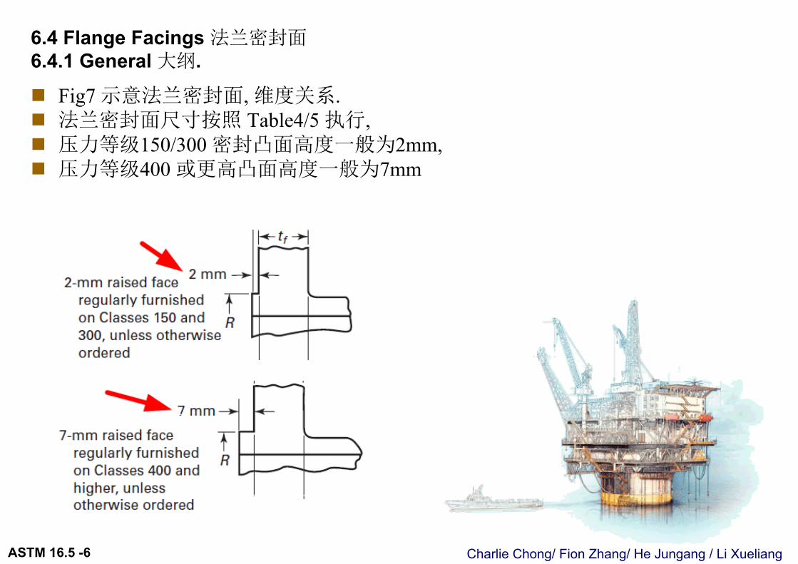
6.4 Flange Facings 法兰密封面6.4.1 General 大纲.
Fig7 示意法兰密封面, 维度关系. 法兰密封面尺寸按照 Table4/5 执行, 压力等级150/300 密封凸面高度一般为2mm, 压力等级400 或更高凸面高度一般为7mm
Charlie Chong/ Fion Zhang/ He Jungang / Li XueliangASTM 16.5 -6
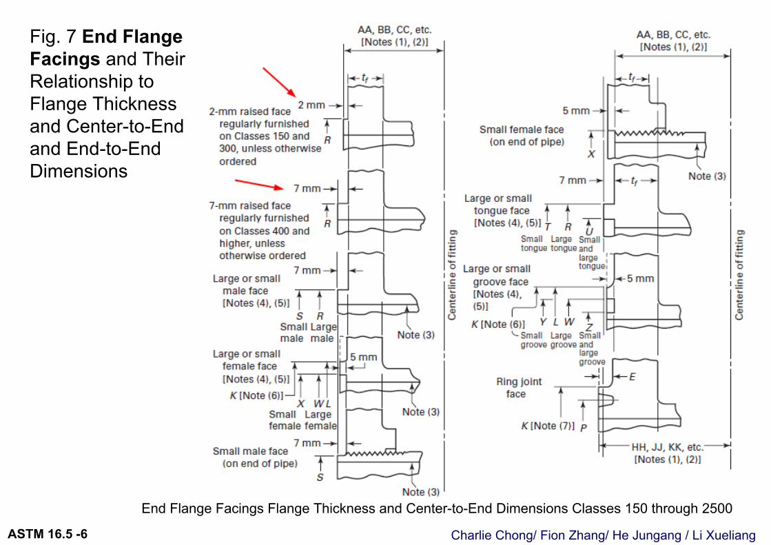
Fig. 7 End Flange Facings and Their Relationship to Flange Thickness and Center-to-End and End-to-End Dimensions
End Flange Facings Flange Thickness and Center-to-End Dimensions Classes 150 through 2500
Charlie Chong/ Fion Zhang/ He Jungang / Li XueliangASTM 16.5 -6
Fig. 7 End Flange Facings and Their Relationship toFlange Thickness and Center-to-Endand End-to-End Dimensions (Cont’d)
End Flange Facings Flange Thickness and End-to-End Dimensions Lapped Joints
Charlie Chong/ Fion Zhang/ He Jungang / Li XueliangASTM 16.5 -6
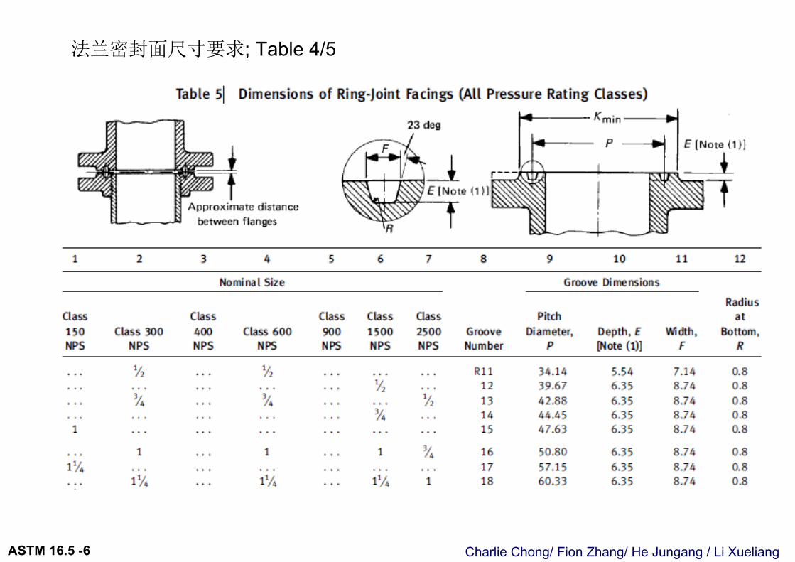
法兰密封面尺寸要求; Table 4/5
Charlie Chong/ Fion Zhang/ He Jungang / Li XueliangASTM 16.5 -6
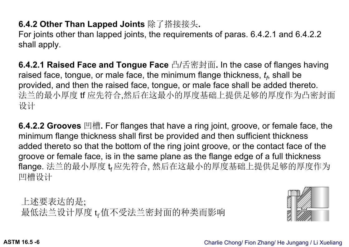
6.4.2 Other Than Lapped Joints 除了搭接接头. For joints other than lapped joints, the requirements of paras. 6.4.2.1 and 6.4.2.2 shall apply.
6.4.2.1 Raised Face and Tongue Face 凸/舌密封面. In the case of flanges having raised face, tongue, or male face, the minimum flange thickness, tf, shall be provided, and then the raised face, tongue, or male face shall be added thereto.法兰的最小厚度 tf 应先符合,然后在这最小的厚度基础上提供足够的厚度作为凸密封面
设计
6.4.2.2 Grooves 凹槽. For flanges that have a ring joint, groove, or female face, the minimum flange thickness shall first be provided and then sufficient thicknessadded thereto so that the bottom of the ring joint groove, or the contact face of the groove or female face, is in the same plane as the flange edge of a full thickness flange. 法兰的最小厚度 tf 应先符合, 然后在这最小的厚度基础上提供足够的厚度作为
凹槽设计
上述要表达的是; 最低法兰设计厚度 tf值不受法兰密封面的种类而影响
Charlie Chong/ Fion Zhang/ He Jungang / Li XueliangASTM 16.5 -6
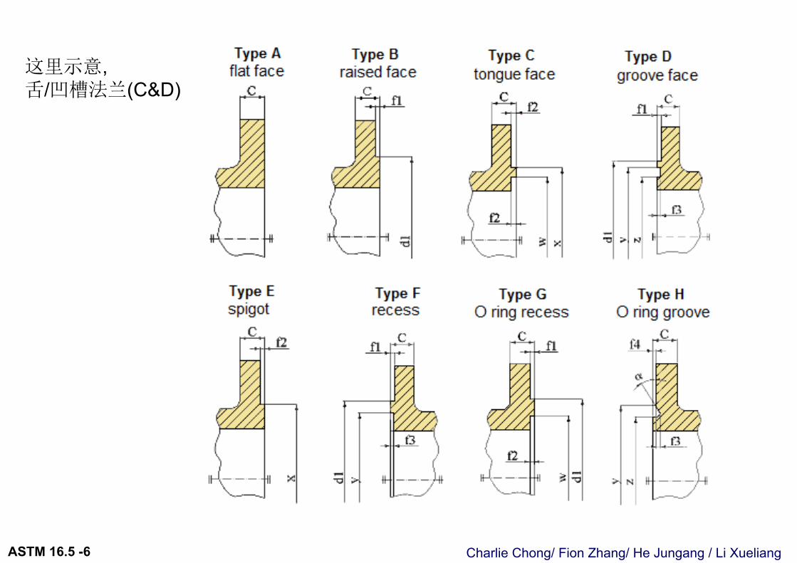
这里示意, 舌/凹槽法兰(C&D)
Charlie Chong/ Fion Zhang/ He Jungang / Li XueliangASTM 16.5 -6
最低法兰设计厚度 tf 值不受法兰密封面的种类而影响
Charlie Chong/ Fion Zhang/ He Jungang / Li XueliangASTM 16.5 -6
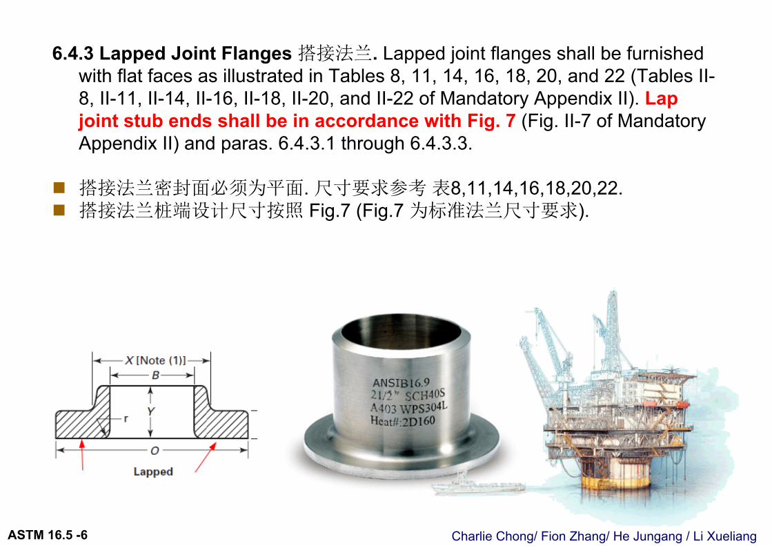
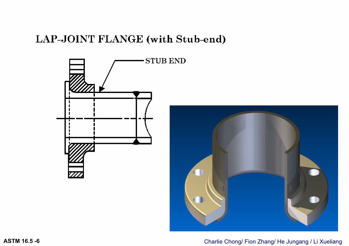
6.4.3 Lapped Joint Flanges 搭接法兰. Lapped joint flanges shall be furnished with flat faces as illustrated in Tables 8, 11, 14, 16, 18, 20, and 22 (Tables II-8, II-11, II-14, II-16, II-18, II-20, and II-22 of Mandatory Appendix II). Lap joint stub ends shall be in accordance with Fig. 7 (Fig. II-7 of Mandatory Appendix II) and paras. 6.4.3.1 through 6.4.3.3.
搭接法兰密封面必须为平面. 尺寸要求参考 表8,11,14,16,18,20,22. 搭接法兰桩端设计尺寸按照 Fig.7 (Fig.7 为标准法兰尺寸要求).
Charlie Chong/ Fion Zhang/ He Jungang / Li XueliangASTM 16.5 -6
Charlie Chong/ Fion Zhang/ He Jungang / Li XueliangASTM 16.5 -6
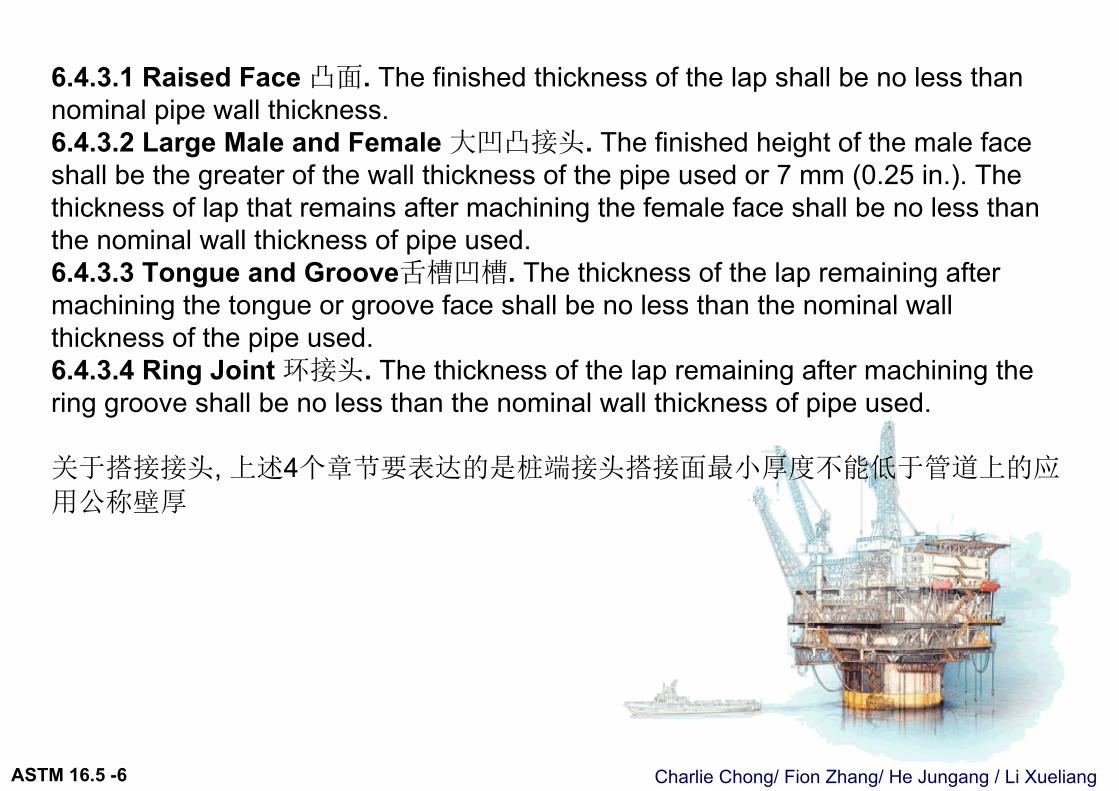
6.4.3.1 Raised Face 凸面. The finished thickness of the lap shall be no less than nominal pipe wall thickness.6.4.3.2 Large Male and Female 大凹凸接头. The finished height of the male face shall be the greater of the wall thickness of the pipe used or 7 mm (0.25 in.). The thickness of lap that remains after machining the female face shall be no less than the nominal wall thickness of pipe used.6.4.3.3 Tongue and Groove舌槽凹槽. The thickness of the lap remaining after machining the tongue or groove face shall be no less than the nominal wall thickness of the pipe used.6.4.3.4 Ring Joint 环接头. The thickness of the lap remaining after machining the ring groove shall be no less than the nominal wall thickness of pipe used.
关于搭接接头, 上述4个章节要表达的是桩端接头搭接面最小厚度不能低于管道上的应
用公称壁厚
Charlie Chong/ Fion Zhang/ He Jungang / Li XueliangASTM 16.5 -6
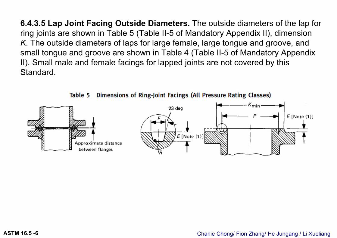
6.4.3.5 Lap Joint Facing Outside Diameters. The outside diameters of the lap for ring joints are shown in Table 5 (Table II-5 of Mandatory Appendix II), dimensionK. The outside diameters of laps for large female, large tongue and groove, and small tongue and groove are shown in Table 4 (Table II-5 of Mandatory Appendix II). Small male and female facings for lapped joints are not covered by this Standard.
Charlie Chong/ Fion Zhang/ He Jungang / Li XueliangASTM 16.5 -6
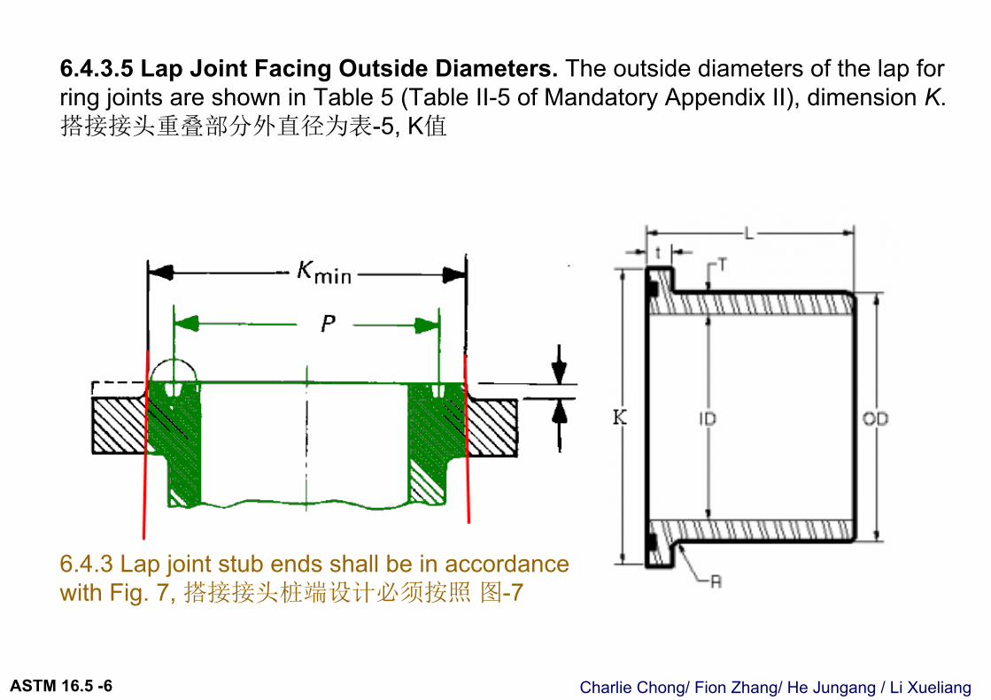
6.4.3.5 Lap Joint Facing Outside Diameters. The outside diameters of the lap for ring joints are shown in Table 5 (Table II-5 of Mandatory Appendix II), dimension K.搭接接头重叠部分外直径为表-5, K值
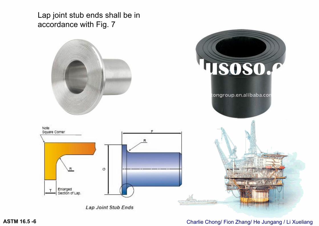
6.4.3 Lap joint stub ends shall be in accordance with Fig. 7, 搭接接头桩端设计必须按照 图-7
Charlie Chong/ Fion Zhang/ He Jungang / Li XueliangASTM 16.5 -6
Lap joint stub ends shall be in accordance with Fig. 7
Charlie Chong/ Fion Zhang/ He Jungang / Li XueliangASTM 16.5 -6
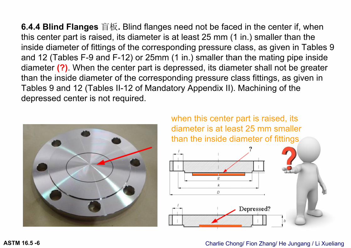
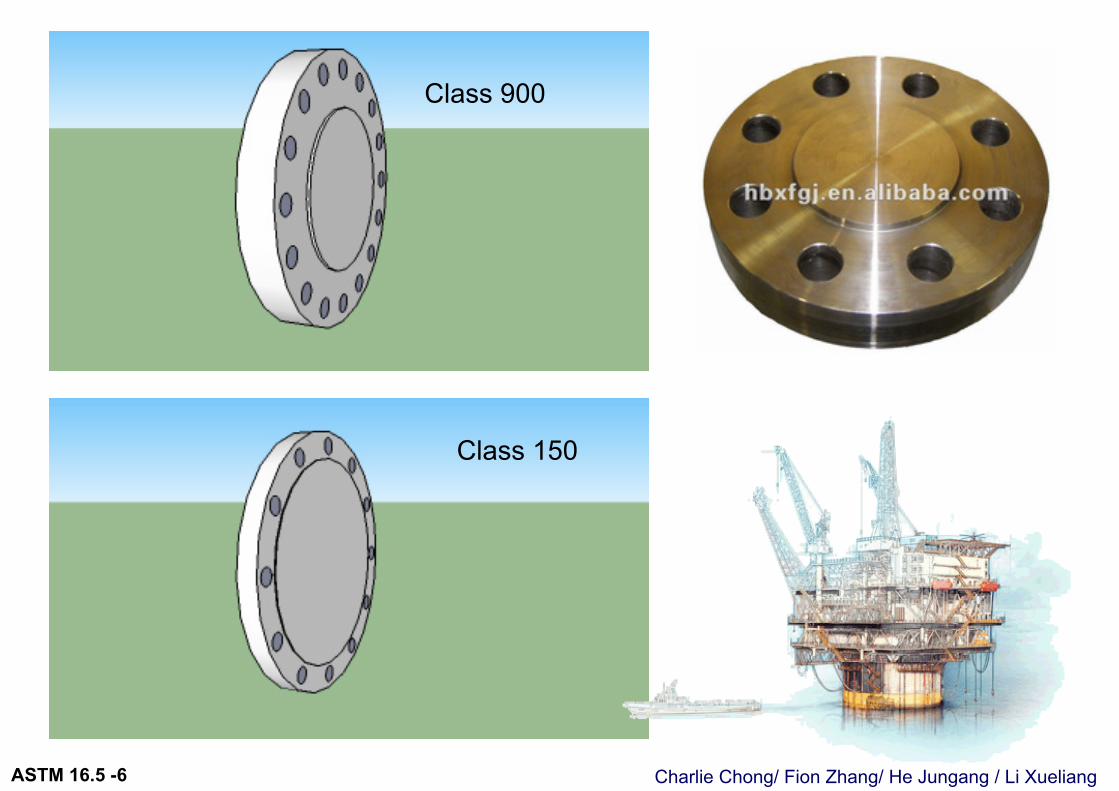
6.4.4 Blind Flanges 盲板. Blind flanges need not be faced in the center if, when this center part is raised, its diameter is at least 25 mm (1 in.) smaller than the inside diameter of fittings of the corresponding pressure class, as given in Tables 9 and 12 (Tables F-9 and F-12) or 25mm (1 in.) smaller than the mating pipe inside diameter (?). When the center part is depressed, its diameter shall not be greater than the inside diameter of the corresponding pressure class fittings, as given in Tables 9 and 12 (Tables II-12 of Mandatory Appendix II). Machining of the depressed center is not required.
when this center part is raised, its diameter is at least 25 mm smaller than the inside diameter of fittings
Charlie Chong/ Fion Zhang/ He Jungang / Li XueliangASTM 16.5 -6
Class 900
Class 150
Charlie Chong/ Fion Zhang/ He Jungang / Li XueliangASTM 16.5 -6
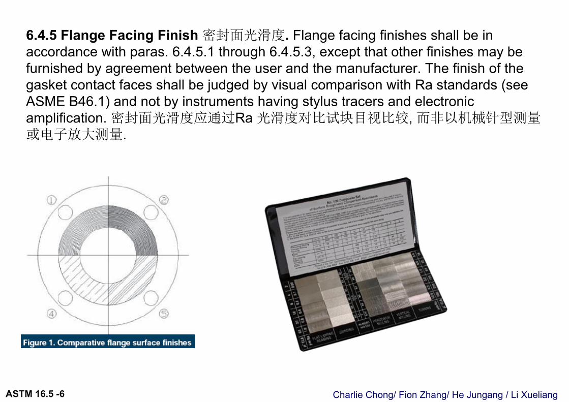
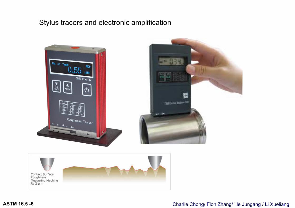
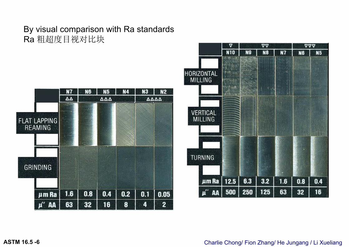
6.4.5 Flange Facing Finish 密封面光滑度. Flange facing finishes shall be in accordance with paras. 6.4.5.1 through 6.4.5.3, except that other finishes may be furnished by agreement between the user and the manufacturer. The finish of the gasket contact faces shall be judged by visual comparison with Ra standards (see ASME B46.1) and not by instruments having stylus tracers and electronic amplification. 密封面光滑度应通过Ra 光滑度对比试块目视比较, 而非以机械针型测量或电子放大测量.
Charlie Chong/ Fion Zhang/ He Jungang / Li XueliangASTM 16.5 -6
Stylus tracers and electronic amplification
Charlie Chong/ Fion Zhang/ He Jungang / Li XueliangASTM 16.5 -6
By visual comparison with Ra standards Ra 粗超度目视对比块
Charlie Chong/ Fion Zhang/ He Jungang / Li XueliangASTM 16.5 -6
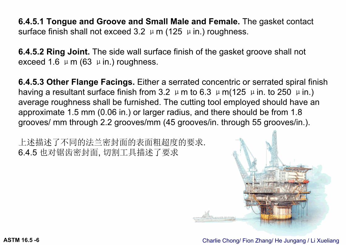
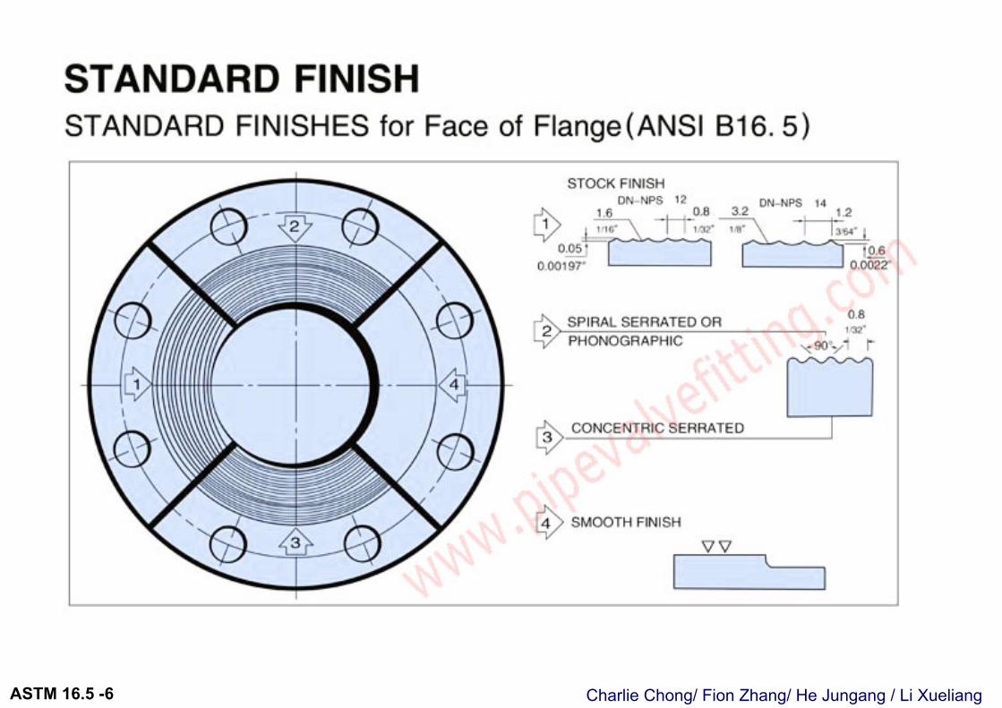
6.4.5.1 Tongue and Groove and Small Male and Female. The gasket contact surface finish shall not exceed 3.2 μm (125 μin.) roughness.
6.4.5.2 Ring Joint. The side wall surface finish of the gasket groove shall not exceed 1.6 μm (63 μin.) roughness.
6.4.5.3 Other Flange Facings. Either a serrated concentric or serrated spiral finish having a resultant surface finish from 3.2 μm to 6.3 μm(125 μin. to 250 μin.) average roughness shall be furnished. The cutting tool employed should have an approximate 1.5 mm (0.06 in.) or larger radius, and there should be from 1.8 grooves/ mm through 2.2 grooves/mm (45 grooves/in. through 55 grooves/in.).
上述描述了不同的法兰密封面的表面粗超度的要求.6.4.5 也对锯齿密封面, 切割工具描述了要求
Charlie Chong/ Fion Zhang/ He Jungang / Li XueliangASTM 16.5 -6
Charlie Chong/ Fion Zhang/ He Jungang / Li XueliangASTM 16.5 -6
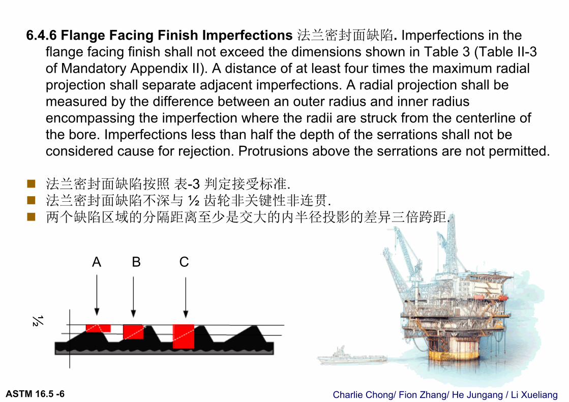
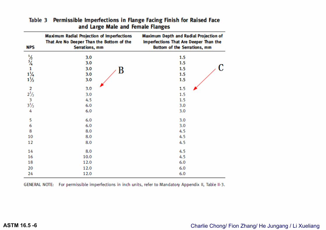
6.4.6 Flange Facing Finish Imperfections 法兰密封面缺陷. Imperfections in the flange facing finish shall not exceed the dimensions shown in Table 3 (Table II-3 of Mandatory Appendix II). A distance of at least four times the maximum radial projection shall separate adjacent imperfections. A radial projection shall be measured by the difference between an outer radius and inner radius encompassing the imperfection where the radii are struck from the centerline of the bore. Imperfections less than half the depth of the serrations shall not be considered cause for rejection. Protrusions above the serrations are not permitted.
法兰密封面缺陷按照 表-3 判定接受标准. 法兰密封面缺陷不深与 ½ 齿轮非关键性非连贯. 两个缺陷区域的分隔距离至少是交大的内半径投影的差异三倍跨距.
A B C
½
Charlie Chong/ Fion Zhang/ He Jungang / Li XueliangASTM 16.5 -6
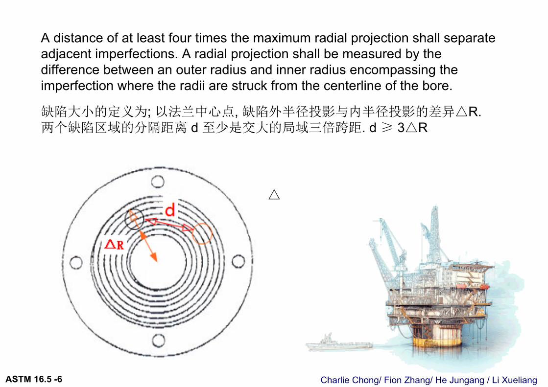
A distance of at least four times the maximum radial projection shall separate adjacent imperfections. A radial projection shall be measured by the difference between an outer radius and inner radius encompassing the imperfection where the radii are struck from the centerline of the bore.
缺陷大小的定义为; 以法兰中心点, 缺陷外半径投影与内半径投影的差异△R. 两个缺陷区域的分隔距离 d 至少是交大的局域三倍跨距. d ≥ 3△R
△
Charlie Chong/ Fion Zhang/ He Jungang / Li XueliangASTM 16.5 -6
Charlie Chong/ Fion Zhang/ He Jungang / Li XueliangASTM 16.5 -6
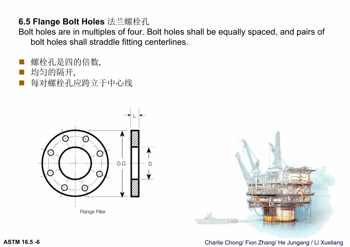
6.5 Flange Bolt Holes 法兰螺栓孔Bolt holes are in multiples of four. Bolt holes shall be equally spaced, and pairs of
bolt holes shall straddle fitting centerlines.
螺栓孔是四的倍数, 均匀的隔开, 每对螺栓孔应跨立于中心线
Charlie Chong/ Fion Zhang/ He Jungang / Li XueliangASTM 16.5 -6
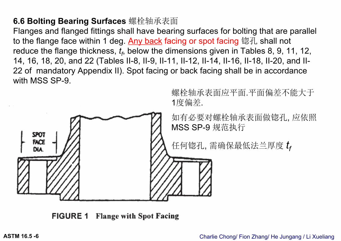
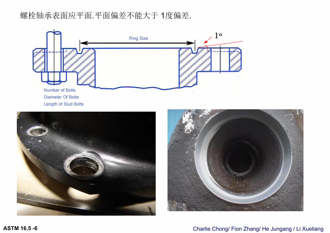
6.6 Bolting Bearing Surfaces 螺栓轴承表面Flanges and flanged fittings shall have bearing surfaces for bolting that are parallel to the flange face within 1 deg. Any back facing or spot facing 锪孔 shall not reduce the flange thickness, tf, below the dimensions given in Tables 8, 9, 11, 12, 14, 16, 18, 20, and 22 (Tables II-8, II-9, II-11, II-12, II-14, II-16, II-18, II-20, and II-22 of mandatory Appendix II). Spot facing or back facing shall be in accordance with MSS SP-9.
螺栓轴承表面应平面.平面偏差不能大于1度偏差.
如有必要对螺栓轴承表面做锪孔, 应依照MSS SP-9 规范执行
任何锪孔, 需确保最低法兰厚度 tf
Charlie Chong/ Fion Zhang/ He Jungang / Li XueliangASTM 16.5 -6
螺栓轴承表面应平面.平面偏差不能大于 1度偏差.
Charlie Chong/ Fion Zhang/ He Jungang / Li XueliangASTM 16.5 -6
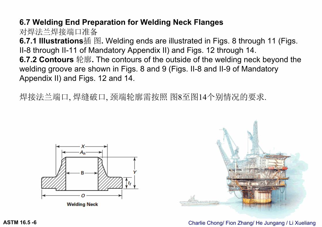
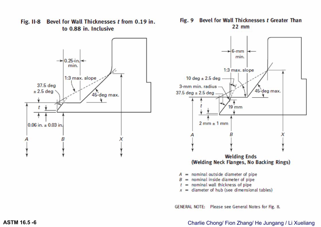
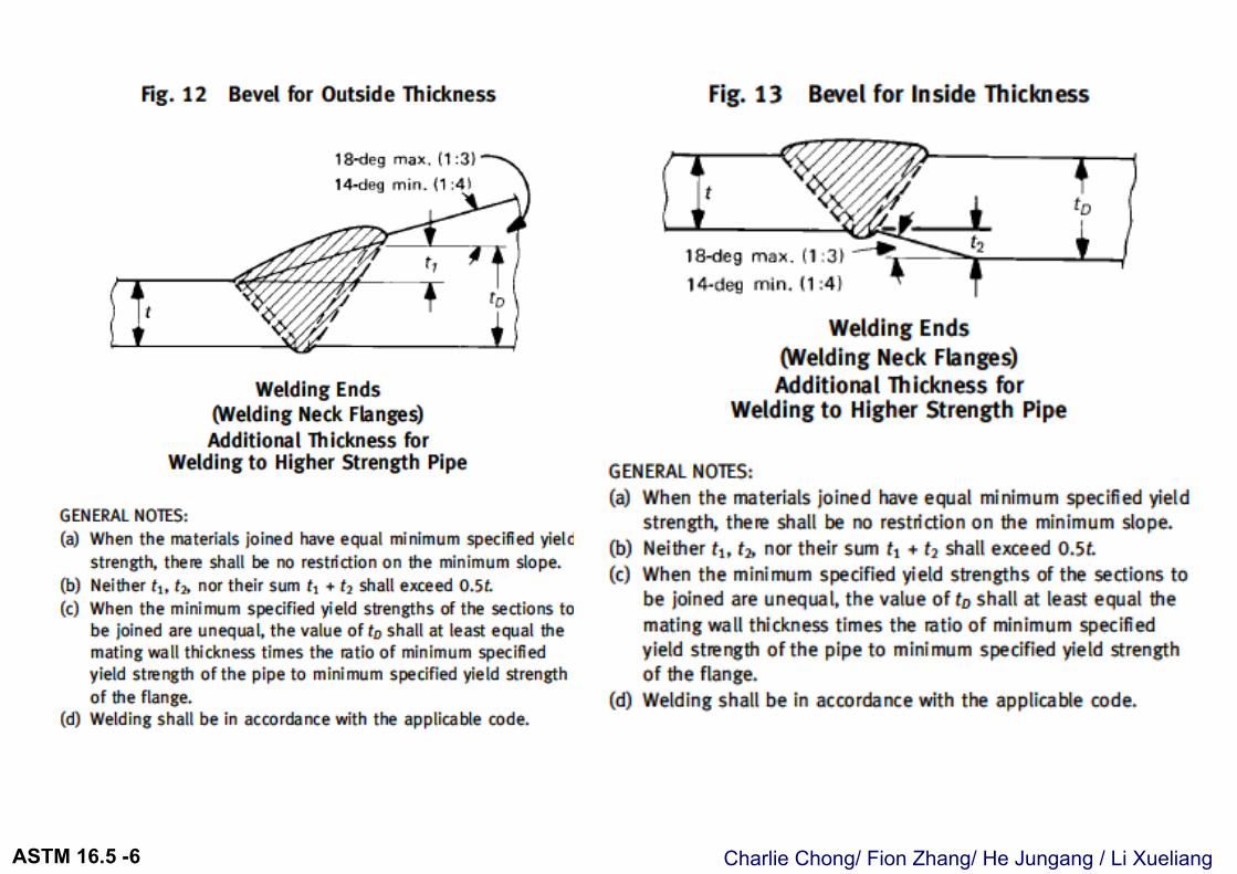
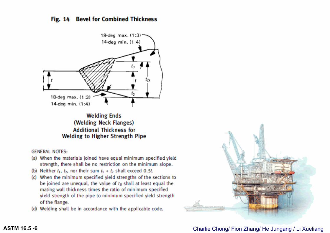
6.7 Welding End Preparation for Welding Neck Flanges对焊法兰焊接端口准备6.7.1 Illustrations插 图. Welding ends are illustrated in Figs. 8 through 11 (Figs. II-8 through II-11 of Mandatory Appendix II) and Figs. 12 through 14.6.7.2 Contours 轮廓. The contours of the outside of the welding neck beyond the welding groove are shown in Figs. 8 and 9 (Figs. II-8 and II-9 of Mandatory Appendix II) and Figs. 12 and 14.
焊接法兰端口, 焊缝破口, 颈端轮廓需按照 图8至图14个别情况的要求.
Charlie Chong/ Fion Zhang/ He Jungang / Li XueliangASTM 16.5 -6
Charlie Chong/ Fion Zhang/ He Jungang / Li XueliangASTM 16.5 -6
Charlie Chong/ Fion Zhang/ He Jungang / Li XueliangASTM 16.5 -6
Charlie Chong/ Fion Zhang/ He Jungang / Li XueliangASTM 16.5 -6
Charlie Chong/ Fion Zhang/ He Jungang / Li XueliangASTM 16.5 -6
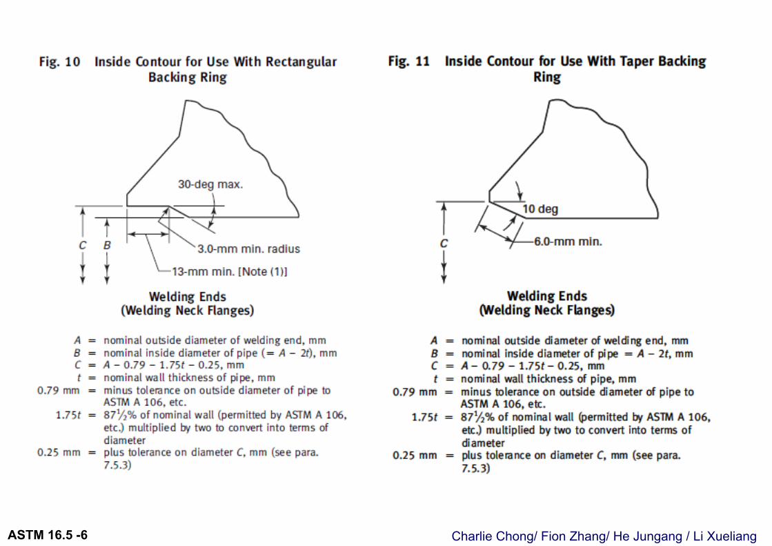
6.7.3 Bores 口径. Straight-through bores shown in Figs. 8 and 9 (Figs. II-8 and II-9 of Mandatory Appendix II) are standard unless specifically ordered to suit the special conditions illustrated in Figs. 10 and 11 (Figs. II-10 and II-11 of Mandatory Appendix II) and Figs. 13 and 14.
6.7.4 Other Welding Ends 其它焊接端口. Other welding end preparations furnished by an agreement of the purchaser and manufacturer do not invalidate compliance with this Standard.
上述的图示8至14描述了不同的口径对接要求. 其它用户, 制作商同意的焊接端口在不违反次标准下是允许的.
Charlie Chong/ Fion Zhang/ He Jungang / Li XueliangASTM 16.5 -6
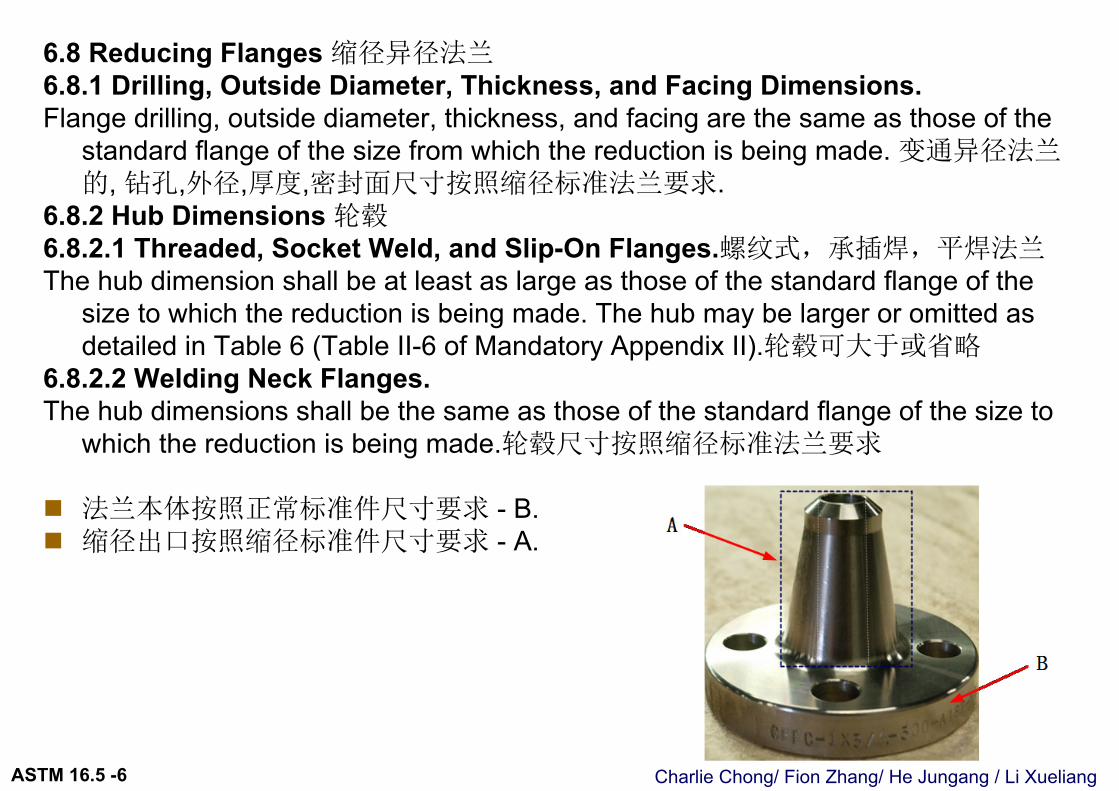
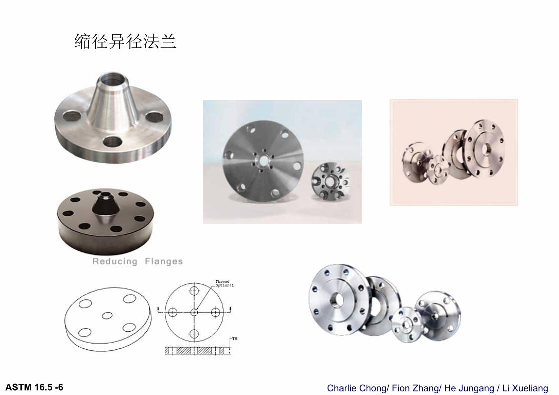
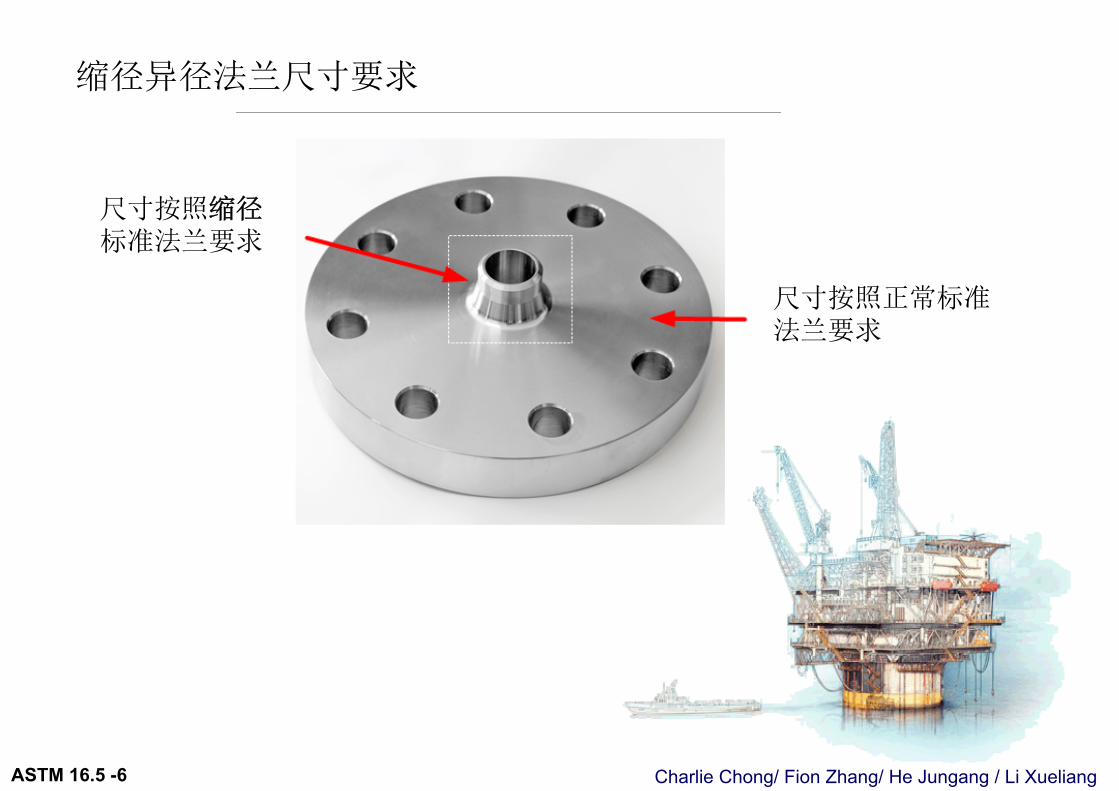
6.8 Reducing Flanges 缩径异径法兰6.8.1 Drilling, Outside Diameter, Thickness, and Facing Dimensions. Flange drilling, outside diameter, thickness, and facing are the same as those of the
standard flange of the size from which the reduction is being made. 变通异径法兰的, 钻孔,外径,厚度,密封面尺寸按照缩径标准法兰要求.
6.8.2 Hub Dimensions 轮毂6.8.2.1 Threaded, Socket Weld, and Slip-On Flanges.螺纹式,承插焊,平焊法兰The hub dimension shall be at least as large as those of the standard flange of the
size to which the reduction is being made. The hub may be larger or omitted as detailed in Table 6 (Table II-6 of Mandatory Appendix II).轮毂可大于或省略
6.8.2.2 Welding Neck Flanges. The hub dimensions shall be the same as those of the standard flange of the size to
which the reduction is being made.轮毂尺寸按照缩径标准法兰要求
法兰本体按照正常标准件尺寸要求 - B. 缩径出口按照缩径标准件尺寸要求 - A.
Charlie Chong/ Fion Zhang/ He Jungang / Li XueliangASTM 16.5 -6
缩径异径法兰
Charlie Chong/ Fion Zhang/ He Jungang / Li XueliangASTM 16.5 -6
尺寸按照缩径标准法兰要求
尺寸按照正常标准法兰要求
缩径异径法兰尺寸要求
Charlie Chong/ Fion Zhang/ He Jungang / Li XueliangASTM 16.5 -6
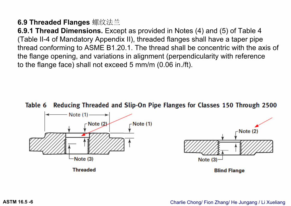
6.9 Threaded Flanges 螺纹法兰6.9.1 Thread Dimensions. Except as provided in Notes (4) and (5) of Table 4 (Table II-4 of Mandatory Appendix II), threaded flanges shall have a taper pipethread conforming to ASME B1.20.1. The thread shall be concentric with the axis of the flange opening, and variations in alignment (perpendicularity with referenceto the flange face) shall not exceed 5 mm/m (0.06 in./ft).
Charlie Chong/ Fion Zhang/ He Jungang / Li XueliangASTM 16.5 -6
Charlie Chong/ Fion Zhang/ He Jungang / Li XueliangASTM 16.5 -6
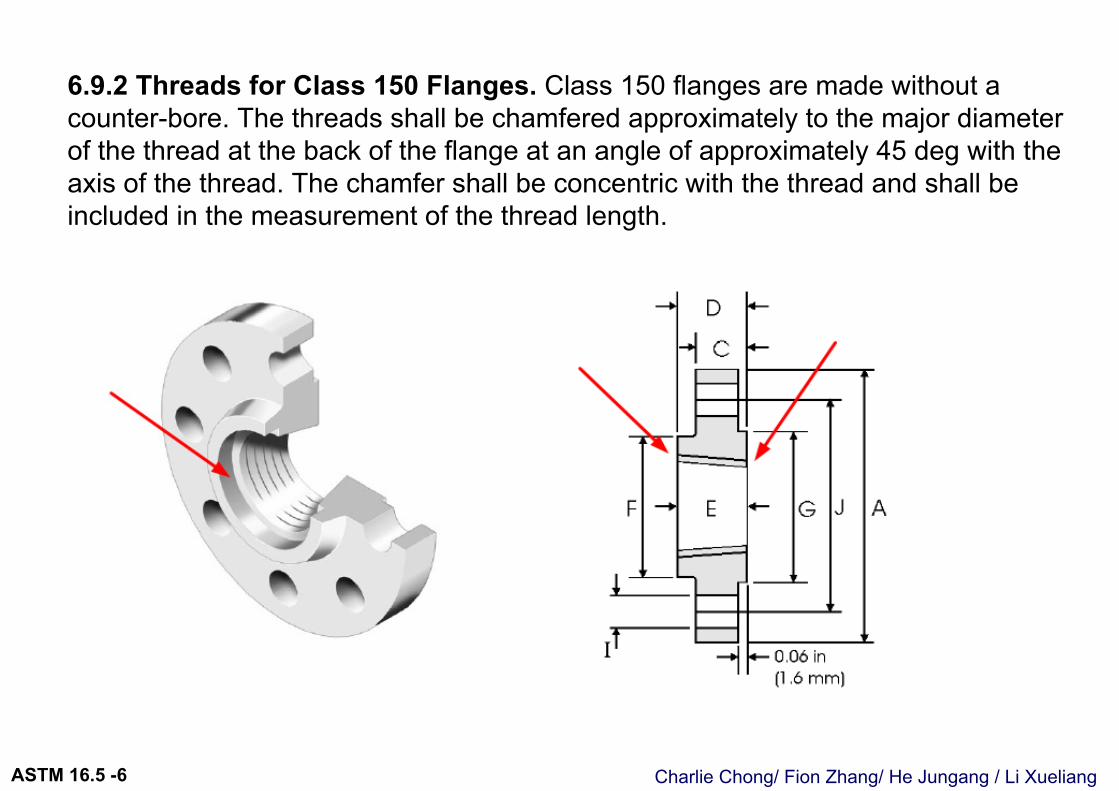
6.9.2 Threads for Class 150 Flanges. Class 150 flanges are made without a counter-bore. The threads shall be chamfered approximately to the major diameterof the thread at the back of the flange at an angle of approximately 45 deg with the axis of the thread. The chamfer shall be concentric with the thread and shall be included in the measurement of the thread length.
Charlie Chong/ Fion Zhang/ He Jungang / Li XueliangASTM 16.5 -6
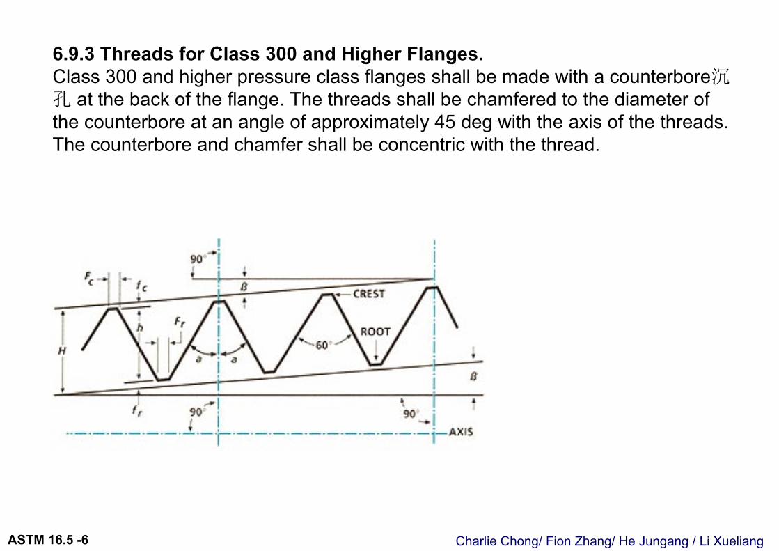
6.9.3 Threads for Class 300 and Higher Flanges.Class 300 and higher pressure class flanges shall be made with a counterbore沉孔 at the back of the flange. The threads shall be chamfered to the diameter of the counterbore at an angle of approximately 45 deg with the axis of the threads. The counterbore and chamfer shall be concentric with the thread.
Charlie Chong/ Fion Zhang/ He Jungang / Li XueliangASTM 16.5 -6
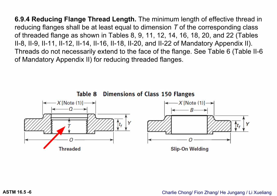
6.9.4 Reducing Flange Thread Length. The minimum length of effective thread in reducing flanges shall be at least equal to dimension T of the corresponding class of threaded flange as shown in Tables 8, 9, 11, 12, 14, 16, 18, 20, and 22 (Tables II-8, II-9, II-11, II-12, II-14, II-16, II-18, II-20, and II-22 of Mandatory Appendix II).Threads do not necessarily extend to the face of the flange. See Table 6 (Table II-6 of Mandatory Appendix II) for reducing threaded flanges.
Charlie Chong/ Fion Zhang/ He Jungang / Li XueliangASTM 16.5 -6
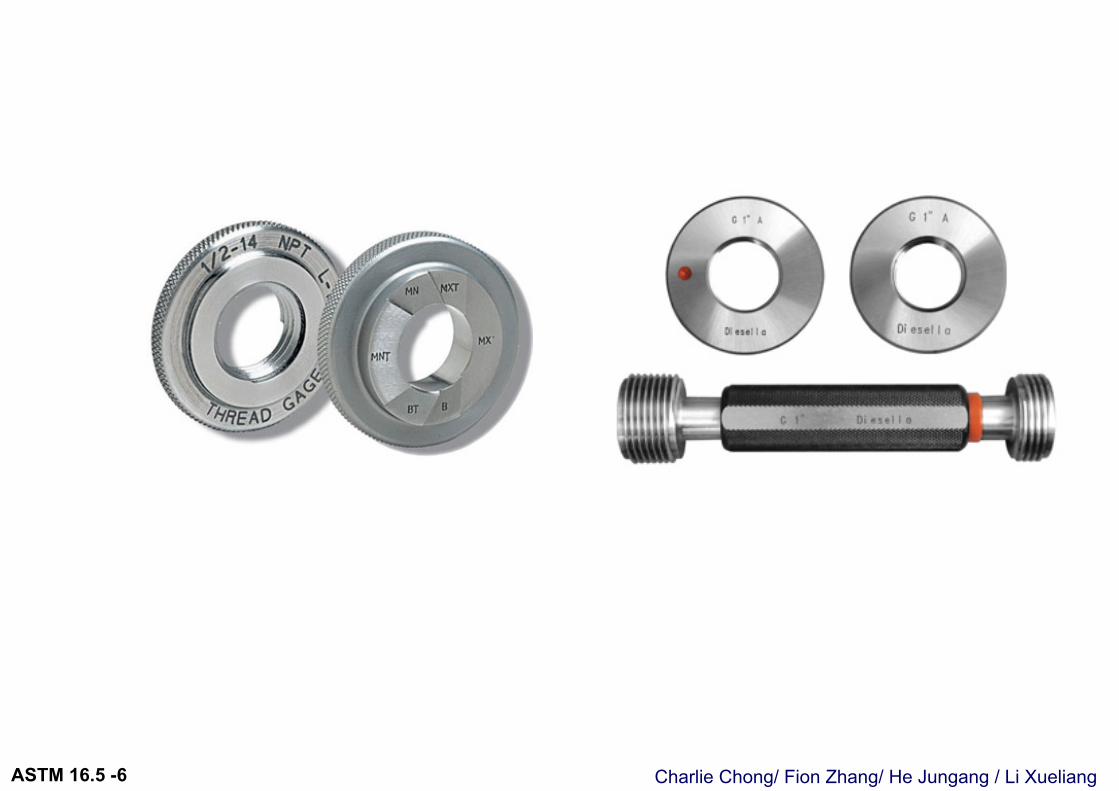
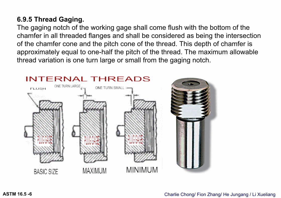
6.9.5 Thread Gaging. The gaging notch of the working gage shall come flush with the bottom of the chamfer in all threaded flanges and shall be considered as being the intersection of the chamfer cone and the pitch cone of the thread. This depth of chamfer is approximately equal to one-half the pitch of the thread. The maximum allowable thread variation is one turn large or small from the gaging notch.
Charlie Chong/ Fion Zhang/ He Jungang / Li XueliangASTM 16.5 -6
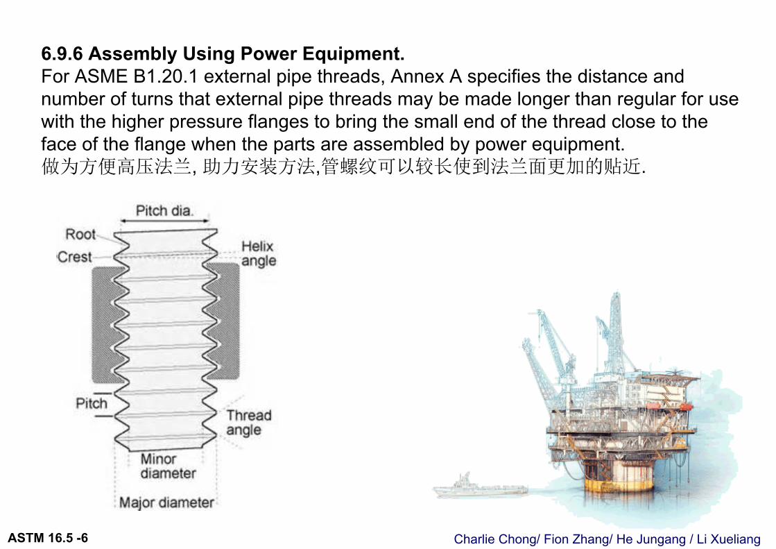
6.9.6 Assembly Using Power Equipment. For ASME B1.20.1 external pipe threads, Annex A specifies the distance and number of turns that external pipe threads may be made longer than regular for use with the higher pressure flanges to bring the small end of the thread close to the face of the flange when the parts are assembled by power equipment.做为方便高压法兰, 助力安装方法,管螺纹可以较长使到法兰面更加的贴近.
Charlie Chong/ Fion Zhang/ He Jungang / Li XueliangASTM 16.5 -6
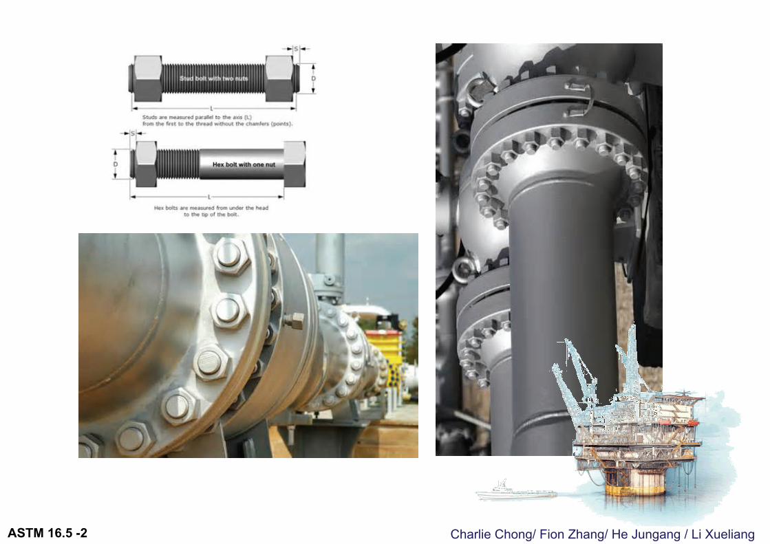
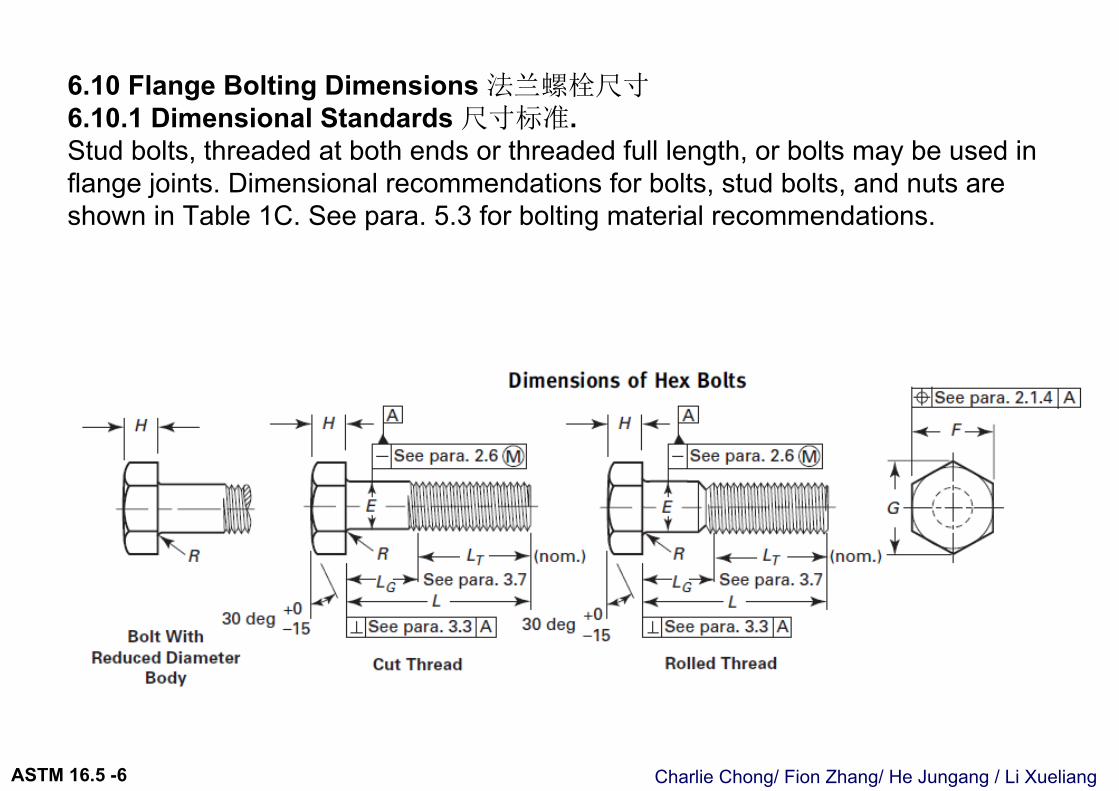
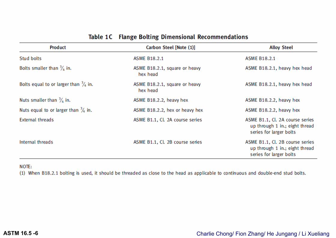
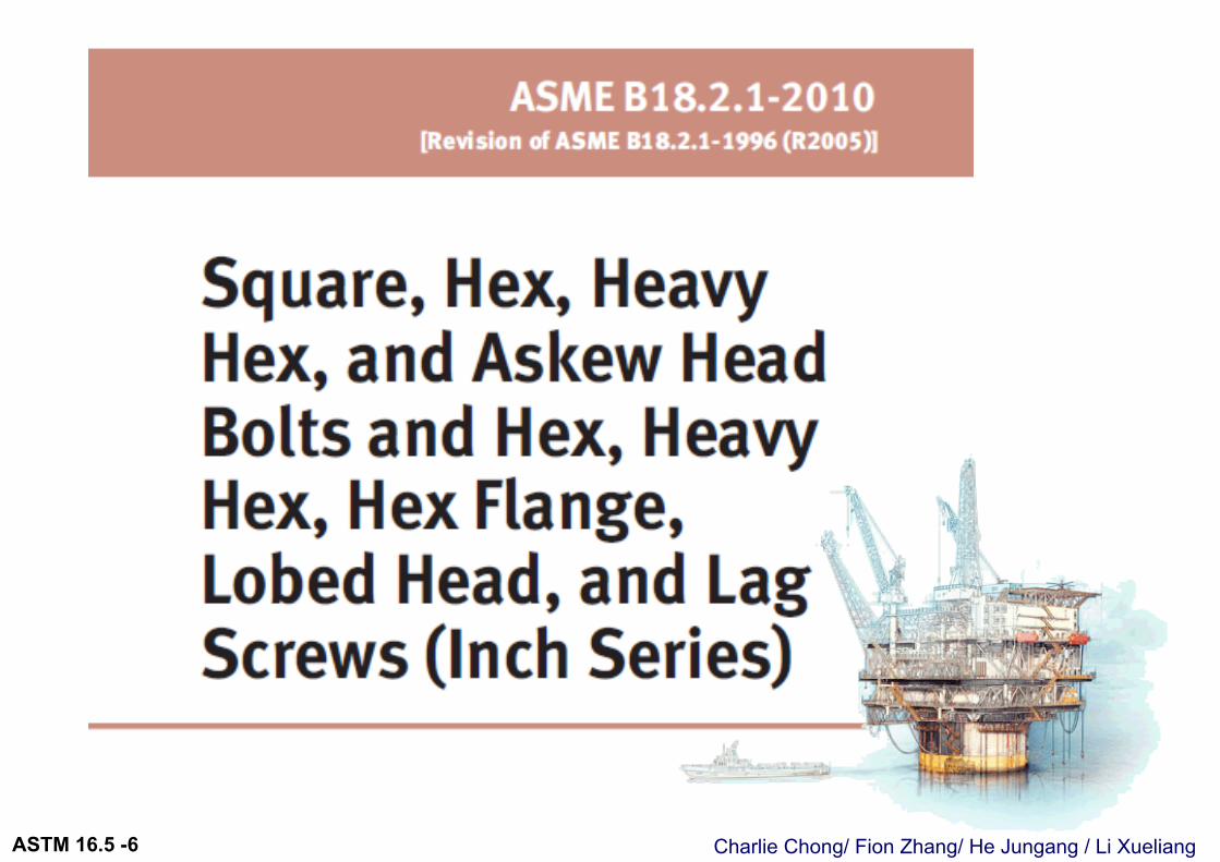
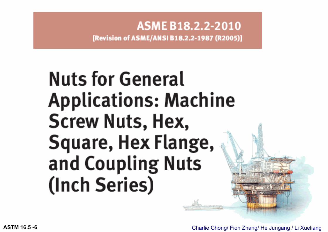
6.10 Flange Bolting Dimensions 法兰螺栓尺寸6.10.1 Dimensional Standards 尺寸标准. Stud bolts, threaded at both ends or threaded full length, or bolts may be used in flange joints. Dimensional recommendations for bolts, stud bolts, and nuts are shown in Table 1C. See para. 5.3 for bolting material recommendations.
Charlie Chong/ Fion Zhang/ He Jungang / Li XueliangASTM 16.5 -6
Charlie Chong/ Fion Zhang/ He Jungang / Li XueliangASTM 16.5 -6
Charlie Chong/ Fion Zhang/ He Jungang / Li XueliangASTM 16.5 -6
Charlie Chong/ Fion Zhang/ He Jungang / Li XueliangASTM 16.5 -6
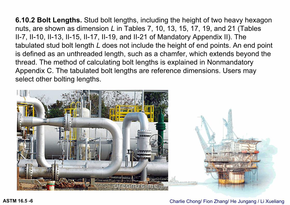
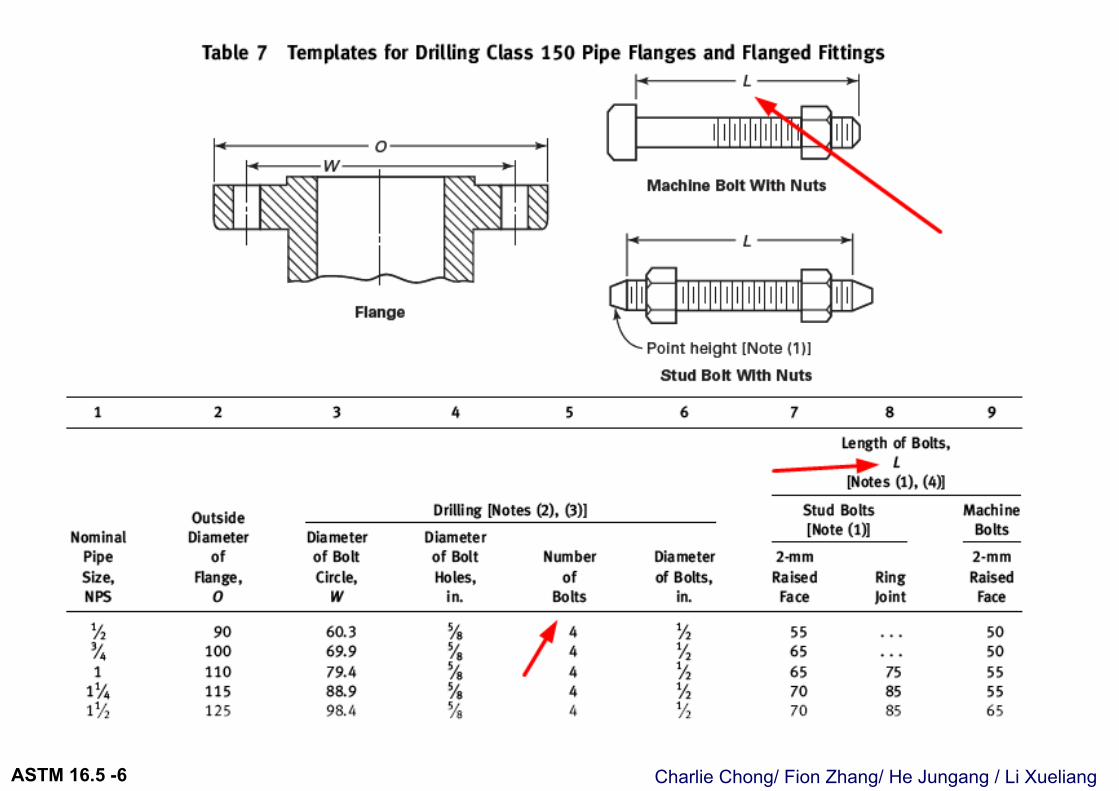
6.10.2 Bolt Lengths. Stud bolt lengths, including the height of two heavy hexagon nuts, are shown as dimension L in Tables 7, 10, 13, 15, 17, 19, and 21 (TablesII-7, II-10, II-13, II-15, II-17, II-19, and II-21 of Mandatory Appendix II). The tabulated stud bolt length L does not include the height of end points. An end point is defined as an unthreaded length, such as a chamfer, which extends beyond the thread. The method of calculating bolt lengths is explained in NonmandatoryAppendix C. The tabulated bolt lengths are reference dimensions. Users may select other bolting lengths.
Charlie Chong/ Fion Zhang/ He Jungang / Li XueliangASTM 16.5 -6
Charlie Chong/ Fion Zhang/ He Jungang / Li XueliangASTM 16.5 -6
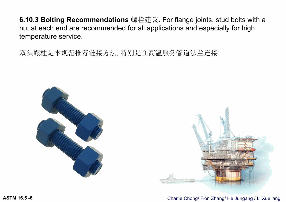
6.10.3 Bolting Recommendations 螺栓建议. For flange joints, stud bolts with a nut at each end are recommended for all applications and especially for high temperature service.
双头螺柱是本规范推荐链接方法, 特别是在高温服务管道法兰连接
Charlie Chong/ Fion Zhang/ He Jungang / Li XueliangASTM 16.5 -6
6.11 Gaskets for Line Flanges6.11.1 Ring Joint. Ring joint gasket dimensions shall conform to ASME B16.20.环垫片尺寸安装 ASME B16.20执行
6.11.2 Contact Width 接触面. For flanges having large or small tongue-and-groove faces, all gaskets, except solid flat metal gaskets, shall cover the bottom of the groove with minimum clearance. [See para. 7.3(a) for tolerance applicable to groove.] Solid flat metal gaskets shall have contact width not greater than for Nonmandatory Appendix B, Group III gaskets. 确保足够的接触面
6.11.3 Bearing Surface 支承表面. For flanges with small male-and-female face, care must be taken to ensure that adequate bearing surface is provided for the gaskets. In particular, care is necessary when the joint is made on the end of the pipe as shown in Fig. 7 (Fig. II-7 of Mandatory Appendix II).应当提供足够的支承表面给予垫片.

Charlie Chong/ Fion Zhang/ He Jungang / Li XueliangASTM 16.5 -6
环垫片尺寸安装 ASME B16.20执行
Charlie Chong/ Fion Zhang/ He Jungang / Li XueliangASTM 16.5 -6
6.12 Auxiliary Connections 辅助连接6.12.1 General. Auxiliary connections or openings for flanged fittings are not required unless specified by the purchaser. Welding to attach auxiliary connectionsto flanged fittings shall be made by a qualified welder using a qualified weld procedure in accordance with Section IX of the ASME Boiler and Pressure Vessel Code.规范没有对辅助连接要求, 一切辅助连接焊接应当按照 ASMEIX 执行.
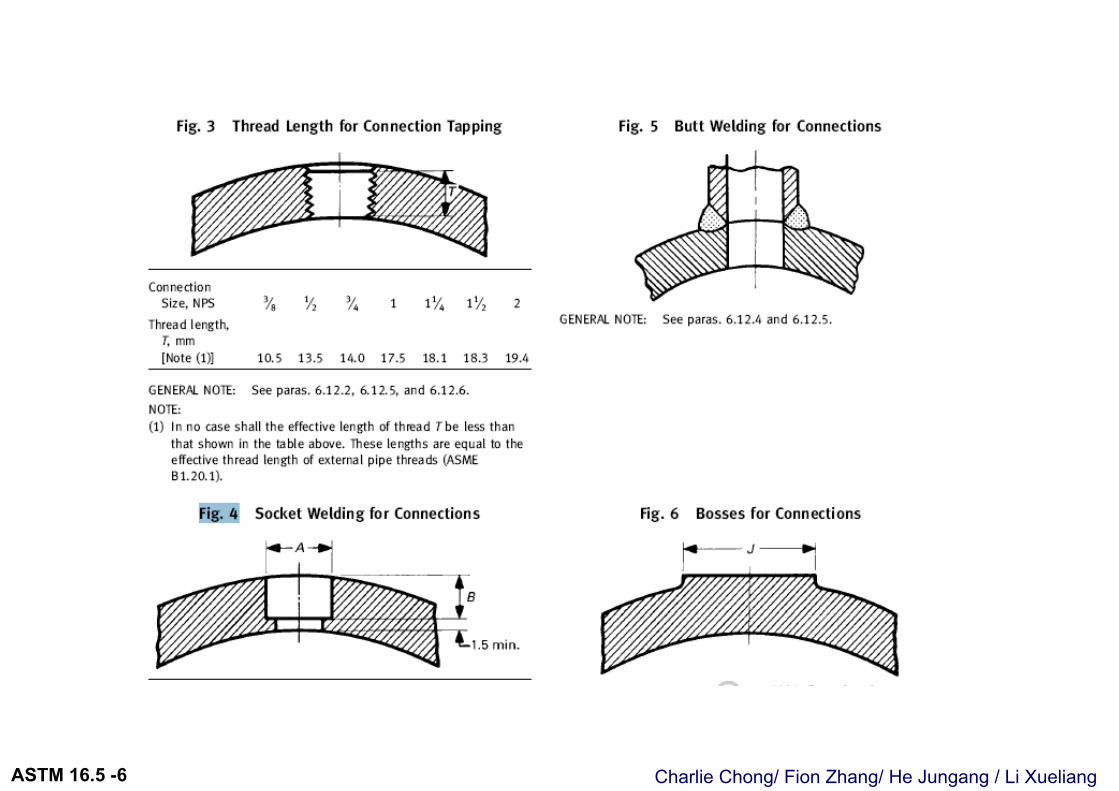
6.12.2 Pipe Thread Tapping. Holes may be tapped in the wall of a fitting if the metal is thick enough to allow the effective thread length specified in Fig. 3 (Fig. II-3 of Mandatory Appendix II). Where thread length is insufficient or the tapped hole needs reinforcement, a boss shall be added.螺栓攻丝, 应当确保足够的工件厚度, 如厚度不充足的情况, 可以应用加固块加强.
Charlie Chong/ Fion Zhang/ He Jungang / Li XueliangASTM 16.5 -6
6.12.3 Sockets. Sockets for socket welding connections may be provided in the wall of a fitting if the metal is thick enough to afford the depth of socket and retaining wall specified in Fig. 4 (Fig. II-4 of Mandatory Appendix II). Where the wall thickness is insufficient, or the size of the connection requires opening reinforcement, a boss shall be added [see Fig. 6 (Fig. II-6 of Mandatory Appendix II)].
6.12.4 Butt Welding. Connections may be attached by butt welding directly to the wall of the fitting [see Fig. 5 (Fig. II-5 of Mandatory Appendix II)]. Where the size of an opening requires reinforcement, a boss shall be added.
6.12.5 Bosses. Where bosses are required, the diameters shall be no less than those shown in Fig. 6 (Fig. II-6 of Mandatory Appendix II), and the height shall provide lengths as specified in Fig. 3 or 4 (Fig. II-3 or II-4 of Mandatory Appendix II).
图4/5 图示承插焊, 对焊接头方式.如厚度不充足的情况, 可以应用加固块加强. 看图示6
Charlie Chong/ Fion Zhang/ He Jungang / Li XueliangASTM 16.5 -6
Charlie Chong/ Fion Zhang/ He Jungang / Li XueliangASTM 16.5 -6
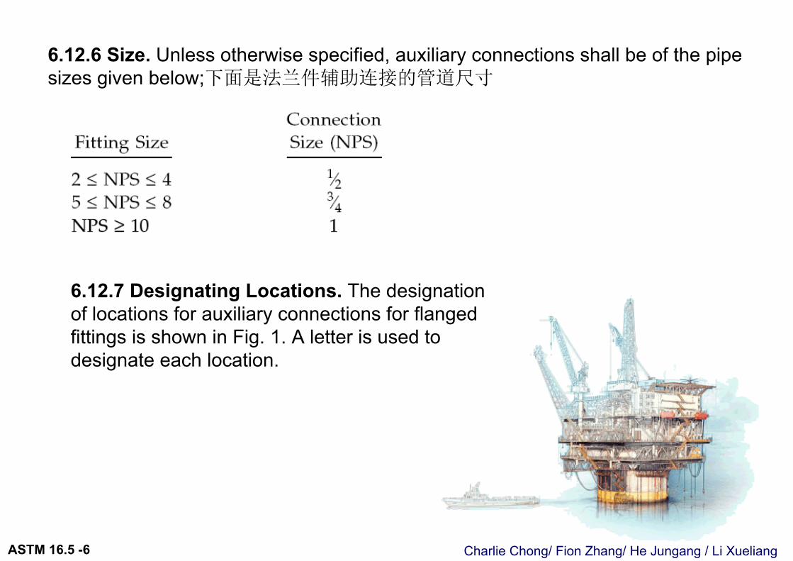
6.12.6 Size. Unless otherwise specified, auxiliary connections shall be of the pipe sizes given below;下面是法兰件辅助连接的管道尺寸
6.12.7 Designating Locations. The designation of locations for auxiliary connections for flanged fittings is shown in Fig. 1. A letter is used to designate each location.
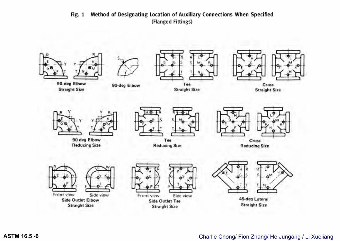
Charlie Chong/ Fion Zhang/ He Jungang / Li XueliangASTM 16.5 -6

Charlie Chong/ Fion Zhang/ He Jungang / Li XueliangASTM 16.5 -6
Charlie Chong/ Fion Zhang/ He Jungang/ Li XueliangASTM 16.5 -7
7 TOLERANCES 公差
Charlie Chong/ Fion Zhang/ He Jungang/ Li XueliangASTM 16.5 -7
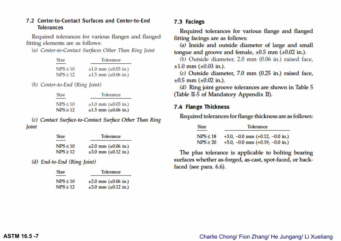
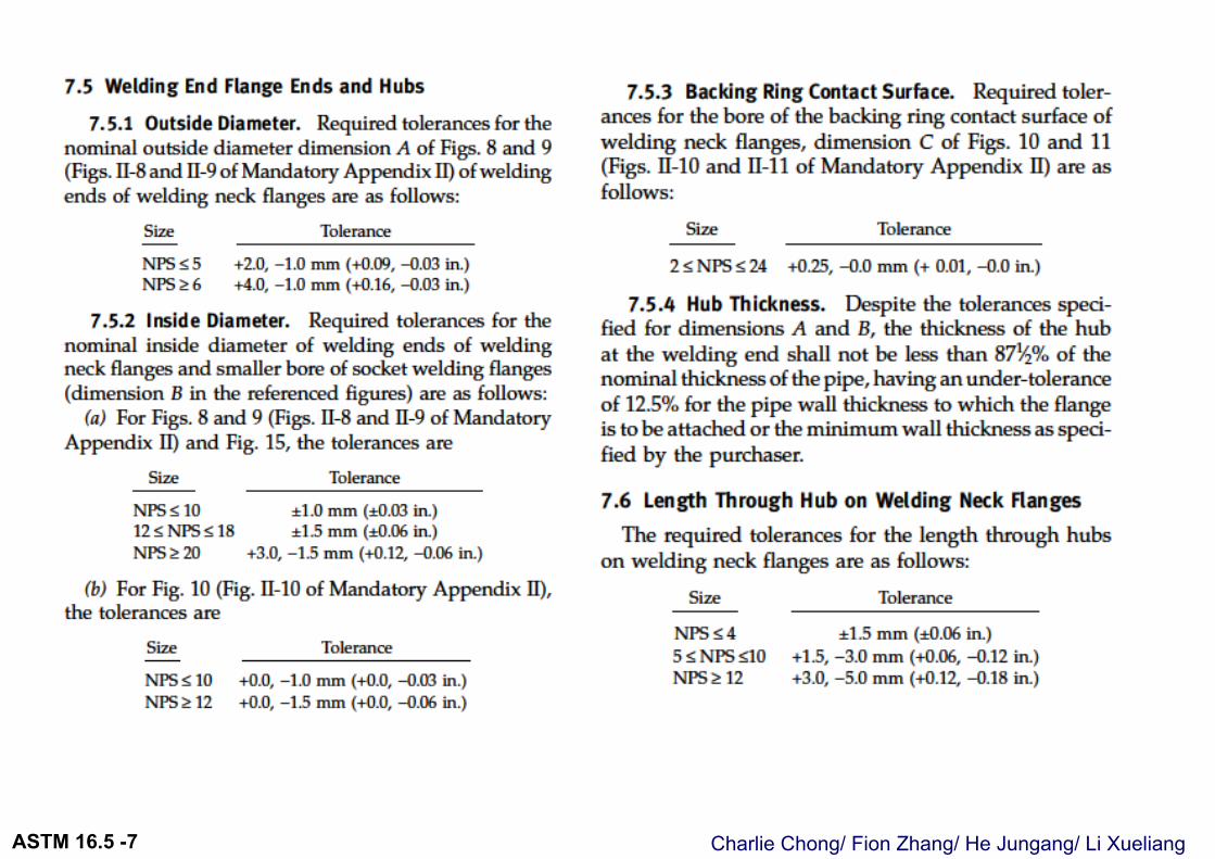
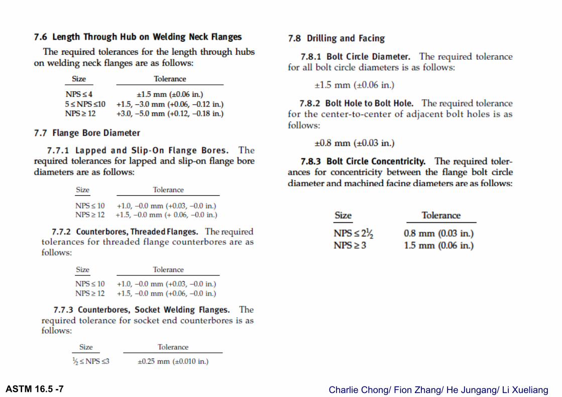
7.1 General 大纲For the purpose of determining conformance with this Standard, the convention for
fixing significant digits where limits, maximum or minimum values, are specified shall be rounded as defined in ASTM Practice E 29. This requires that an observed or calculated value shall be rounded to the nearest unit in the last right-hand digit used for expressing the limit. The listing of decimal tolerances does not imply a particular method of measurement.
公差精密度按照此规范要求, 后尾点数公差依照 ASTM Practice E29 方法处理. 尾数的公差要求不代表对度量衡工具有任何特殊要求.
Charlie Chong/ Fion Zhang/ He Jungang/ Li XueliangASTM 16.5 -7
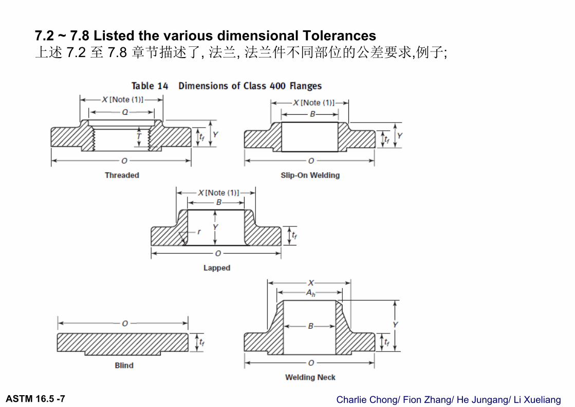
7.2 ~ 7.8 Listed the various dimensional Tolerances上述 7.2 至 7.8 章节描述了, 法兰, 法兰件不同部位的公差要求,例子;
Charlie Chong/ Fion Zhang/ He Jungang/ Li XueliangASTM 16.5 -7
Charlie Chong/ Fion Zhang/ He Jungang/ Li XueliangASTM 16.5 -7
Charlie Chong/ Fion Zhang/ He Jungang/ Li XueliangASTM 16.5 -7
Charlie Chong/ Fion Zhang/ He Jungang/ Li XueliangASTM 16.5 -7
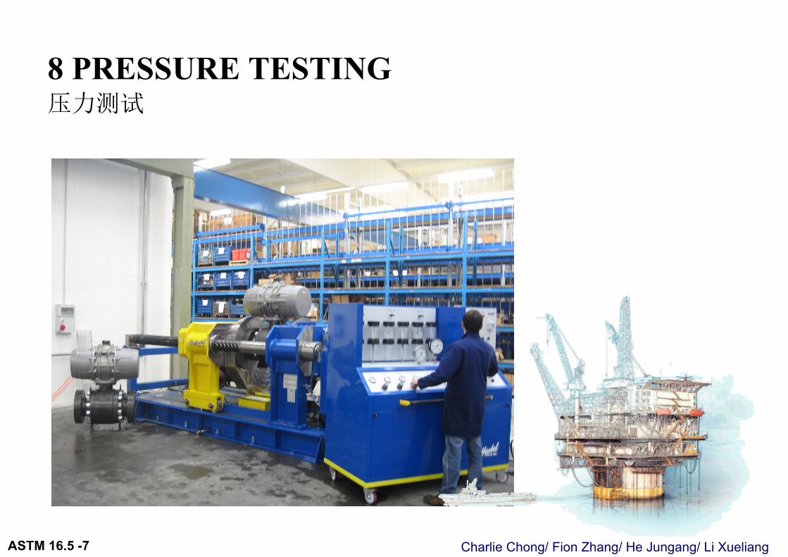
8 PRESSURE TESTING 压力测试
Charlie Chong/ Fion Zhang/ He Jungang/ Li XueliangASTM 16.5 -7
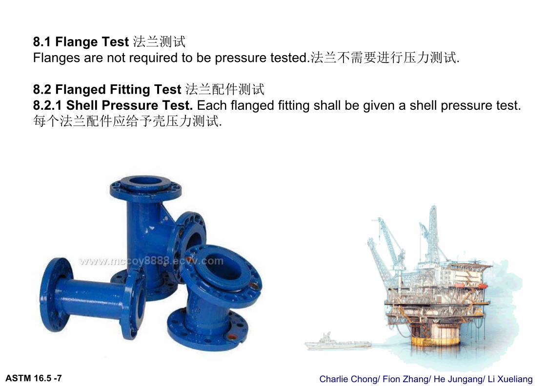
8.1 Flange Test 法兰测试Flanges are not required to be pressure tested.法兰不需要进行压力测试.
8.2 Flanged Fitting Test 法兰配件测试8.2.1 Shell Pressure Test. Each flanged fitting shall be given a shell pressure test.每个法兰配件应给予壳压力测试.
Charlie Chong/ Fion Zhang/ He Jungang/ Li XueliangASTM 16.5 -7
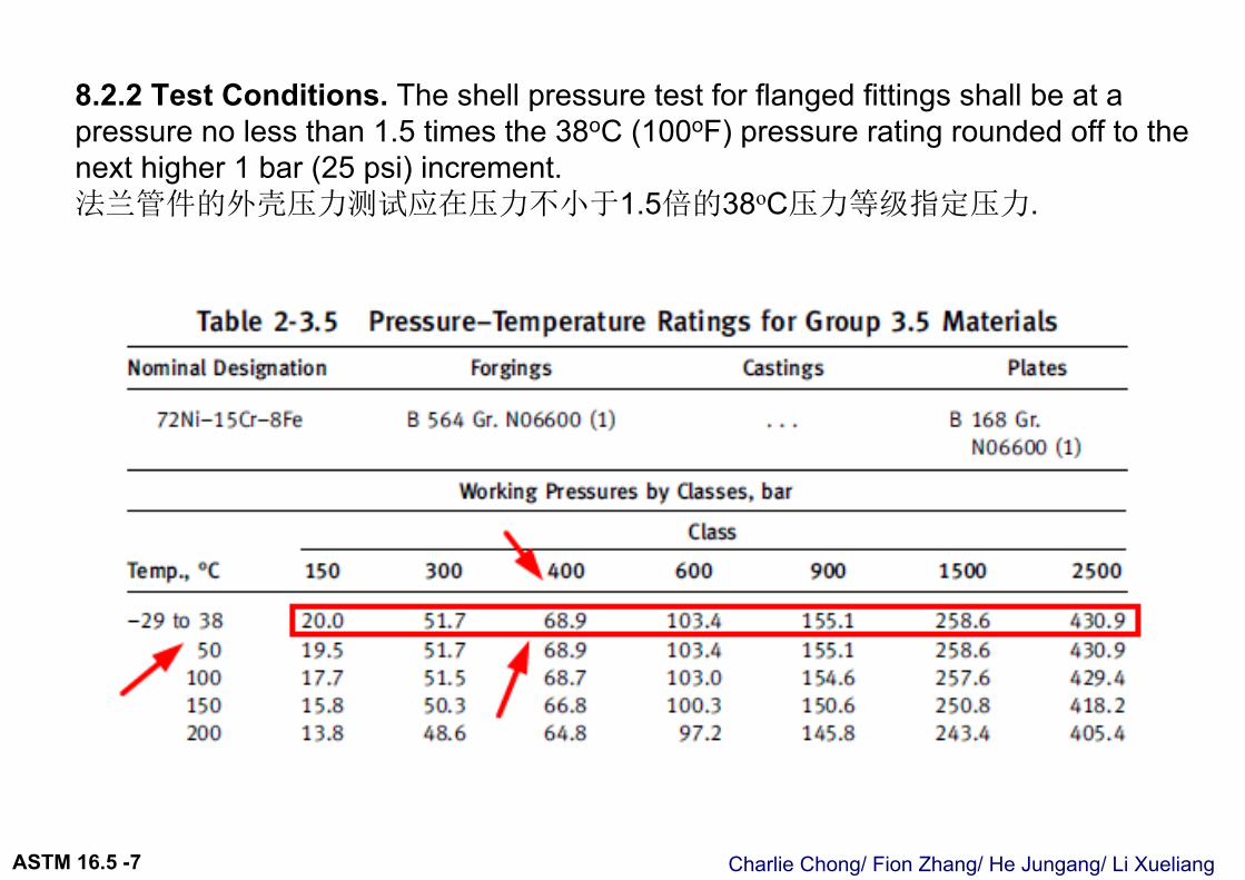
8.2.2 Test Conditions. The shell pressure test for flanged fittings shall be at a pressure no less than 1.5 times the 38oC (100oF) pressure rating rounded off to the next higher 1 bar (25 psi) increment.法兰管件的外壳压力测试应在压力不小于1.5倍的38oC压力等级指定压力.
Charlie Chong/ Fion Zhang/ He Jungang/ Li XueliangASTM 16.5 -7
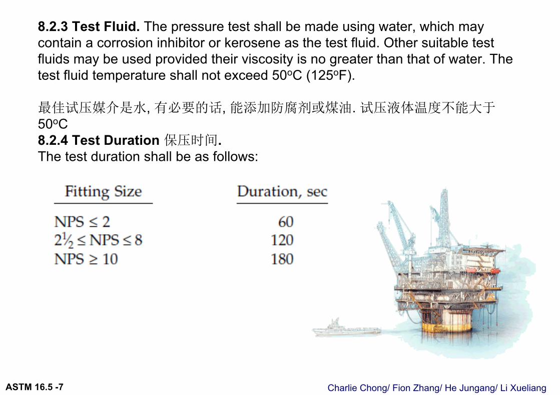
8.2.3 Test Fluid. The pressure test shall be made using water, which may contain a corrosion inhibitor or kerosene as the test fluid. Other suitable test fluids may be used provided their viscosity is no greater than that of water. The test fluid temperature shall not exceed 50oC (125oF).
最佳试压媒介是水, 有必要的话, 能添加防腐剂或煤油. 试压液体温度不能大于50oC8.2.4 Test Duration 保压时间. The test duration shall be as follows:
Charlie Chong/ Fion Zhang/ He Jungang/ Li XueliangASTM 16.5 -7
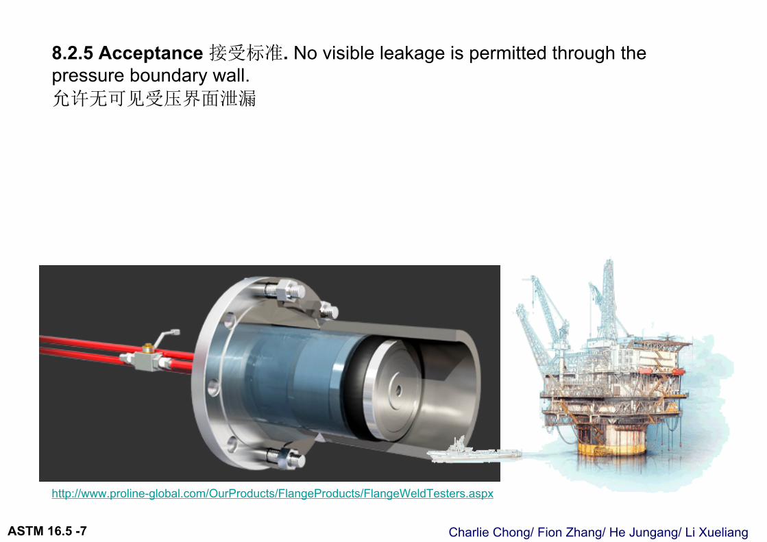
8.2.5 Acceptance 接受标准. No visible leakage is permitted through the pressure boundary wall.允许无可见受压界面泄漏
http://www.proline-global.com/OurProducts/FlangeProducts/FlangeWeldTesters.aspx

Charlie Chong/ Fion Zhang/ He Jungang/ Li XueliangASTM 16.5 -7

Charlie Chong/ Fion Zhang/ He Jungang / Li Xueliang

Charlie Chong/ Fion Zhang/ He Jungang/ Li XueliangASTM 16.5 –Q&A
Review on ASME B16.5

Charlie Chong/ Fion Zhang/ He Jungang/ Li XueliangASTM 16.5 –Q&A
Charlie Chong/ Fion Zhang/ He Jungang/ Li XueliangASTM 16.5 –Q&A
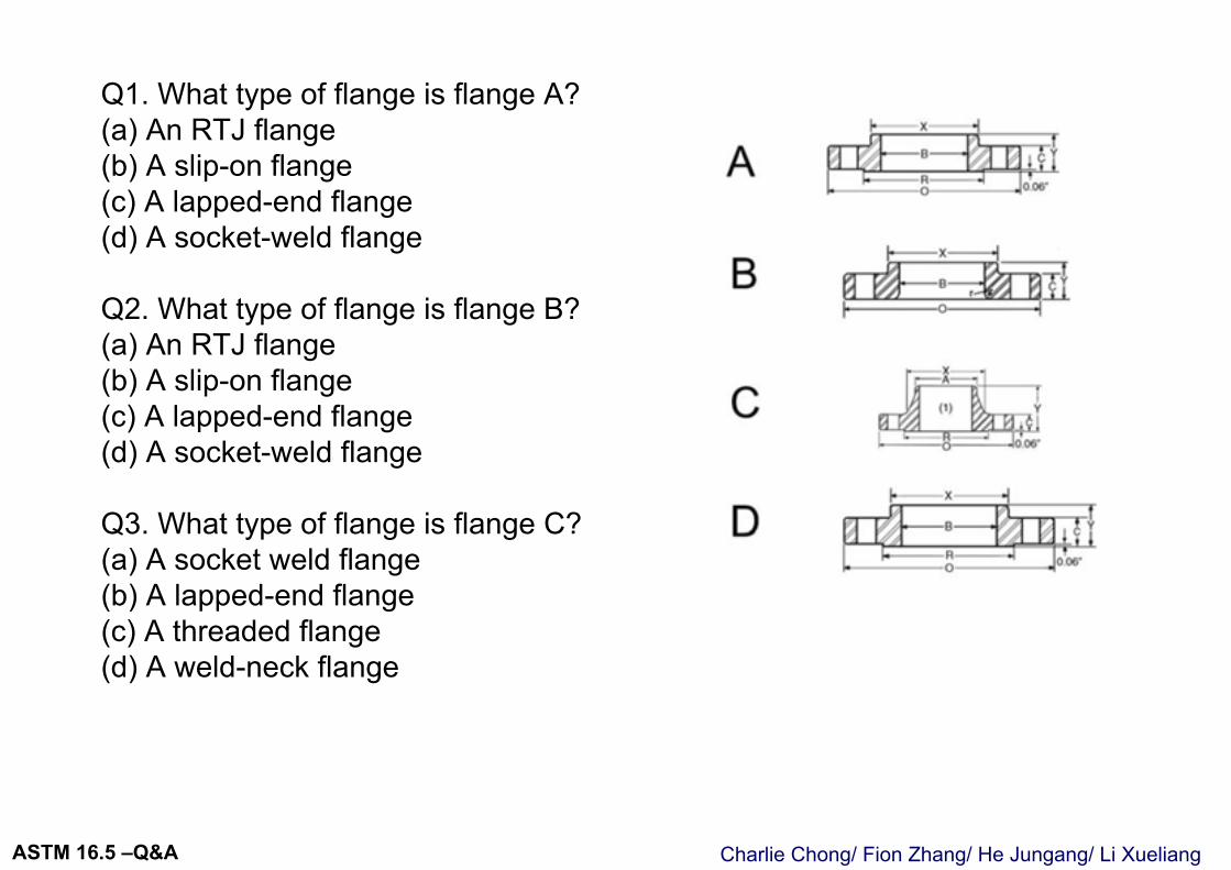
Q1. What type of flange is flange A?(a) An RTJ flange (b) A slip-on flange (c) A lapped-end flange (d) A socket-weld flange
Q2. What type of flange is flange B?(a) An RTJ flange (b) A slip-on flange (c) A lapped-end flange (d) A socket-weld flange
Q3. What type of flange is flange C?(a) A socket weld flange (b) A lapped-end flange (c) A threaded flange (d) A weld-neck flange
Charlie Chong/ Fion Zhang/ He Jungang/ Li XueliangASTM 16.5 –Q&A
Q4. What is the maximum size of flange covered byASME B16.5?(a) NPS 12 (b) NPS 20 (c) NPS 24 (d) NPS 36
Q5. What does a #150 flange class designation mean?(a) The maximum flange working pressure is 150 psi (b) The maximum flange test pressure is 150 psi (c) The maximum flange working pressure is 150 psi at 100 8F(d) None of the above
Q6. Which parameter in Fig. 13.1 for flange Drepresents the flange wall thickness?(a) c (b) (RB)/2 (c) (xB)/2 (d) (Rx)/2
Charlie Chong/ Fion Zhang/ He Jungang/ Li XueliangASTM 16.5 –Q&A
Q7. Which of these flanges made of the same material would you expect to have the highest safe working pressure at 200oF?
(a) #150 NPS 4 (b) #300 NPS 4 (c) #1500 NPS 4 (d) #2500 NPS 4
Q8. What is the format of the pressure units used in ASME B16.5?(a) psig (kPa) (b) kPa (psig) (c) psig and barg(d) psig only
9. Which of the following items must be marked on all flanges or flanged fittings?a. Temperatureb. Actual working pressurec. ASTM material specificationd. Hydrotest pressure

Charlie Chong/ Fion Zhang/ He Jungang/ Li XueliangASTM 16.5 –Q&A
Charlie Chong/ Fion Zhang/ He Jungang/ Li XueliangASTM 16.5 –Q&A
CLOSED BOOK QUESTIONS ( 1 ~ 15 )
Charlie Chong/ Fion Zhang/ He Jungang/ Li XueliangASTM 16.5 –Q&A
1. ASME B 16.5 does not cover:a. Class 150 flangesb. Class 300 flanged fittingsc. Butt welded pipe capsd. All of the above
2. The maximum hydrostatic test pressure permitted for a flange in a system hydrostatic test is:
a. Not requiredb. Conducted at 1.5 x class rating @1000Fc. Conducted at 25 psi above class ratingd. Required only for welded flanges
3. “High strength” bolting is described as equivalent to:a. ASTM A 193 B5b. ASTM A 193 B7c. ASTM 320 GR8d. Any high carbon steel bolt
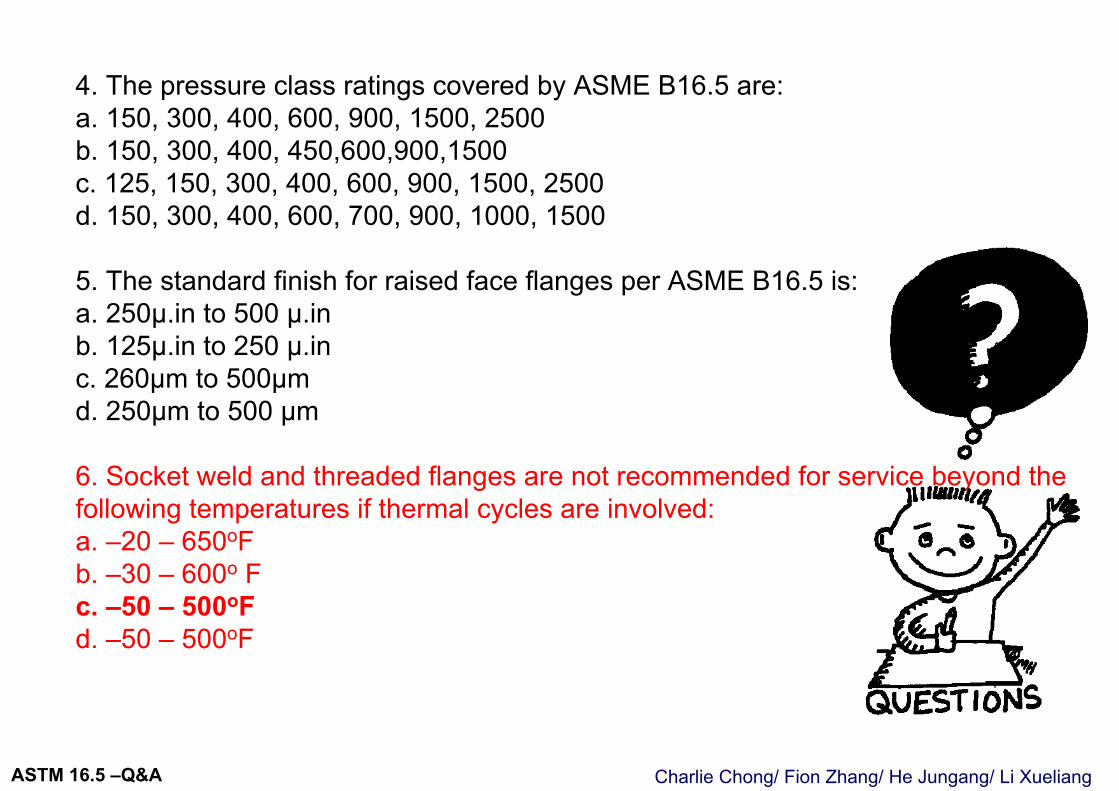
Charlie Chong/ Fion Zhang/ He Jungang/ Li XueliangASTM 16.5 –Q&A
4. The pressure class ratings covered by ASME B16.5 are:a. 150, 300, 400, 600, 900, 1500, 2500b. 150, 300, 400, 450,600,900,1500c. 125, 150, 300, 400, 600, 900, 1500, 2500d. 150, 300, 400, 600, 700, 900, 1000, 1500
5. The standard finish for raised face flanges per ASME B16.5 is:a. 250µ.in to 500 µ.inb. 125µ.in to 250 µ.inc. 260µm to 500µmd. 250µm to 500 µm
6. Socket weld and threaded flanges are not recommended for service beyond the following temperatures if thermal cycles are involved:a. –20 – 650oFb. –30 – 600o Fc. –50 – 500oFd. –50 – 500oF
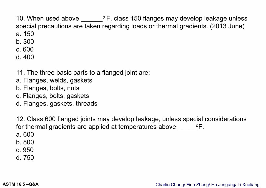
Charlie Chong/ Fion Zhang/ He Jungang/ Li XueliangASTM 16.5 –Q&A
10. When used above ______o F, class 150 flanges may develop leakage unless special precautions are taken regarding loads or thermal gradients. (2013 June)a. 150b. 300c. 600d. 400
11. The three basic parts to a flanged joint are:a. Flanges, welds, gasketsb. Flanges, bolts, nutsc. Flanges, bolts, gasketsd. Flanges, gaskets, threads
12. Class 600 flanged joints may develop leakage, unless special considerations for thermal gradients are applied at temperatures above _____oF.a. 600b. 800c. 950d. 750
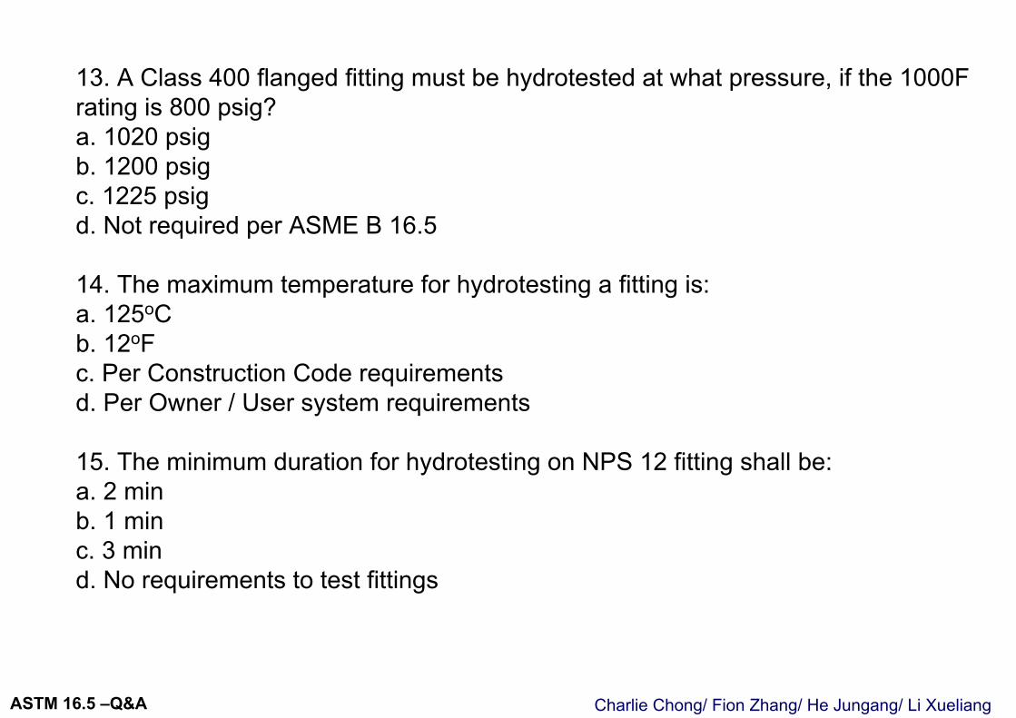
Charlie Chong/ Fion Zhang/ He Jungang/ Li XueliangASTM 16.5 –Q&A
13. A Class 400 flanged fitting must be hydrotested at what pressure, if the 1000F rating is 800 psig?a. 1020 psigb. 1200 psigc. 1225 psigd. Not required per ASME B 16.5
14. The maximum temperature for hydrotesting a fitting is:a. 125oCb. 12oFc. Per Construction Code requirementsd. Per Owner / User system requirements
15. The minimum duration for hydrotesting on NPS 12 fitting shall be:a. 2 minb. 1 minc. 3 mind. No requirements to test fittings
Charlie Chong/ Fion Zhang/ He Jungang/ Li XueliangASTM 16.5 –Q&A
OPEN BOOK QUESTIONS ( 16 ~ 32 )
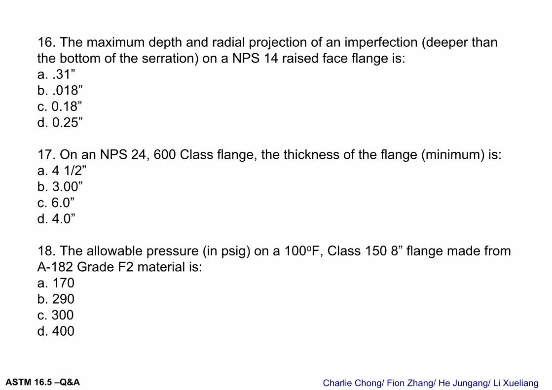
Charlie Chong/ Fion Zhang/ He Jungang/ Li XueliangASTM 16.5 –Q&A
16. The maximum depth and radial projection of an imperfection (deeper than the bottom of the serration) on a NPS 14 raised face flange is:a. .31”b. .018”c. 0.18”d. 0.25”
17. On an NPS 24, 600 Class flange, the thickness of the flange (minimum) is:a. 4 1/2”b. 3.00”c. 6.0”d. 4.0”
18. The allowable pressure (in psig) on a 100oF, Class 150 8” flange made from A-182 Grade F2 material is:a. 170b. 290c. 300d. 400
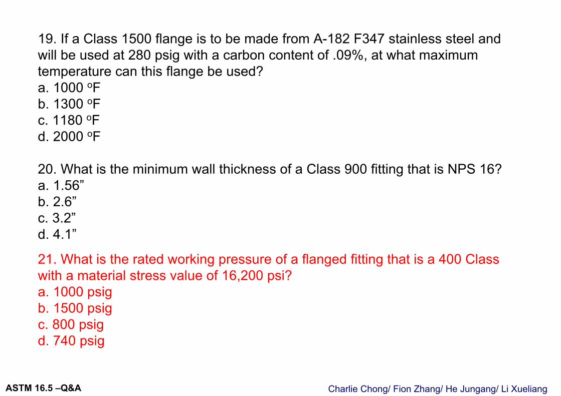
Charlie Chong/ Fion Zhang/ He Jungang/ Li XueliangASTM 16.5 –Q&A
19. If a Class 1500 flange is to be made from A-182 F347 stainless steel and will be used at 280 psig with a carbon content of .09%, at what maximum temperature can this flange be used?a. 1000 oFb. 1300 oFc. 1180 oFd. 2000 oF
20. What is the minimum wall thickness of a Class 900 fitting that is NPS 16?a. 1.56”b. 2.6”c. 3.2”d. 4.1”
21. What is the rated working pressure of a flanged fitting that is a 400 Class with a material stress value of 16,200 psi?a. 1000 psigb. 1500 psigc. 800 psigd. 740 psig
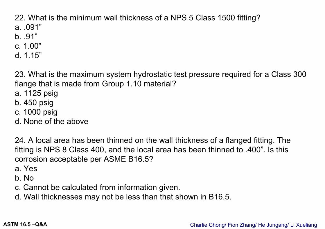
Charlie Chong/ Fion Zhang/ He Jungang/ Li XueliangASTM 16.5 –Q&A
22. What is the minimum wall thickness of a NPS 5 Class 1500 fitting?a. .091”b. .91”c. 1.00”d. 1.15”
23. What is the maximum system hydrostatic test pressure required for a Class 300 flange that is made from Group 1.10 material?a. 1125 psigb. 450 psigc. 1000 psigd. None of the above
24. A local area has been thinned on the wall thickness of a flanged fitting. The fitting is NPS 8 Class 400, and the local area has been thinned to .400”. Is this corrosion acceptable per ASME B16.5?a. Yesb. Noc. Cannot be calculated from information given.d. Wall thicknesses may not be less than that shown in B16.5.
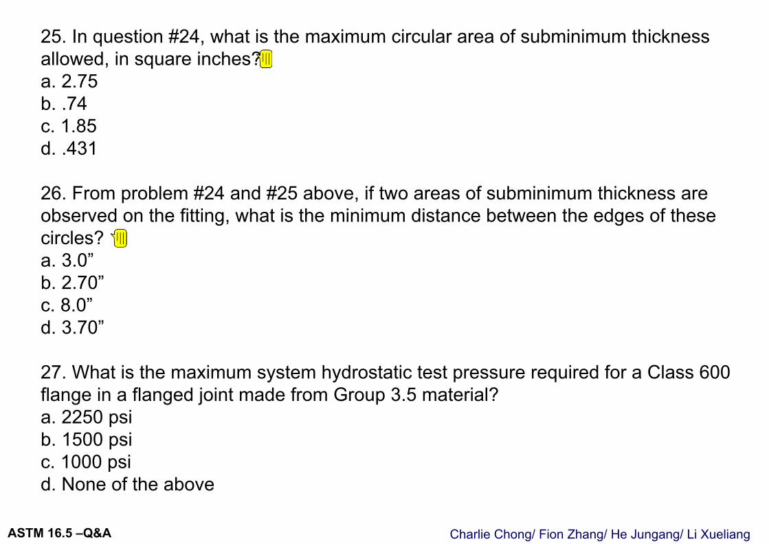
Charlie Chong/ Fion Zhang/ He Jungang/ Li XueliangASTM 16.5 –Q&A
25. In question #24, what is the maximum circular area of subminimum thickness allowed, in square inches?a. 2.75b. .74c. 1.85d. .431
26. From problem #24 and #25 above, if two areas of subminimum thickness are observed on the fitting, what is the minimum distance between the edges of these circles?a. 3.0”b. 2.70”c. 8.0”d. 3.70”
27. What is the maximum system hydrostatic test pressure required for a Class 600 flange in a flanged joint made from Group 3.5 material?a. 2250 psib. 1500 psic. 1000 psid. None of the above
Valentino
附注
NPS 8 Class 400 D=0.35(dtm) 1/2 D=0.35(8x0.56) 1/2 D=0.741 Area= PiD2/4 Area= 0.431in2 #
Valentino
附注
NPS 8 Class 400 d=1.75(dtm) 1/2 d=1.75(8x0.56) 1/2 d=3.70in
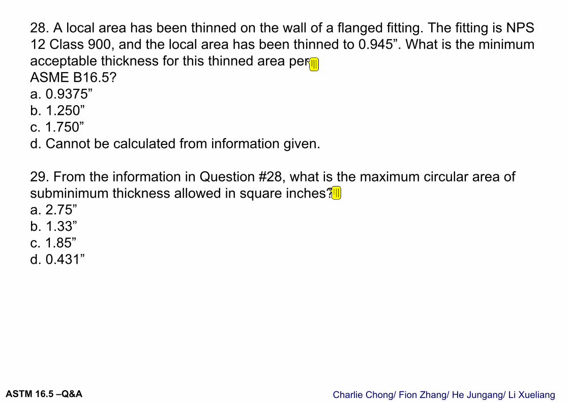
Charlie Chong/ Fion Zhang/ He Jungang/ Li XueliangASTM 16.5 –Q&A
28. A local area has been thinned on the wall of a flanged fitting. The fitting is NPS 12 Class 900, and the local area has been thinned to 0.945”. What is the minimum acceptable thickness for this thinned area perASME B16.5?a. 0.9375”b. 1.250”c. 1.750”d. Cannot be calculated from information given.
29. From the information in Question #28, what is the maximum circular area of subminimum thickness allowed in square inches?a. 2.75”b. 1.33”c. 1.85”d. 0.431”
Valentino
附注
0.75tm t= 0.75x 1.25
Valentino
附注
NPS 12 Class 900 D=0.35(dtm) 1/2 D=0.35(11.12x1.25) 1/2 D=1.305 Area= PiD2/4 Area= 1.33in2 #
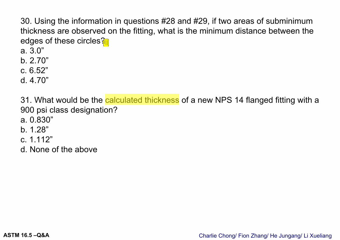
Charlie Chong/ Fion Zhang/ He Jungang/ Li XueliangASTM 16.5 –Q&A
30. Using the information in questions #28 and #29, if two areas of subminimum thickness are observed on the fitting, what is the minimum distance between the edges of these circles?a. 3.0”b. 2.70”c. 6.52”d. 4.70”
31. What would be the calculated thickness of a new NPS 14 flanged fitting with a 900 psi class designation?a. 0.830”b. 1.28”c. 1.112”d. None of the above
Valentino
附注
NPS 12 Class 900 d=1.75(dtm) 1/2 d=1.75(11.12x1.25) 1/2 d=6.52in
Valentino
高亮
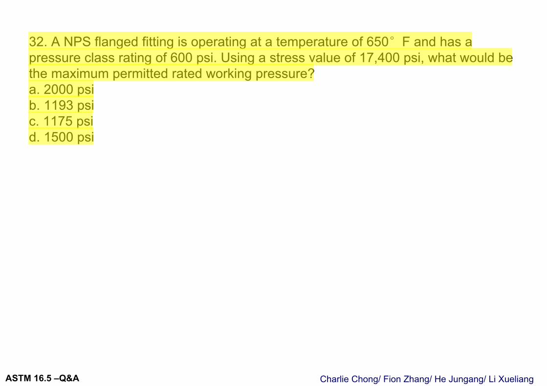
Charlie Chong/ Fion Zhang/ He Jungang/ Li XueliangASTM 16.5 –Q&A
32. A NPS flanged fitting is operating at a temperature of 650°F and has a pressure class rating of 600 psi. Using a stress value of 17,400 psi, what would be the maximum permitted rated working pressure?a. 2000 psib. 1193 psic. 1175 psid. 1500 psi
Valentino
高亮
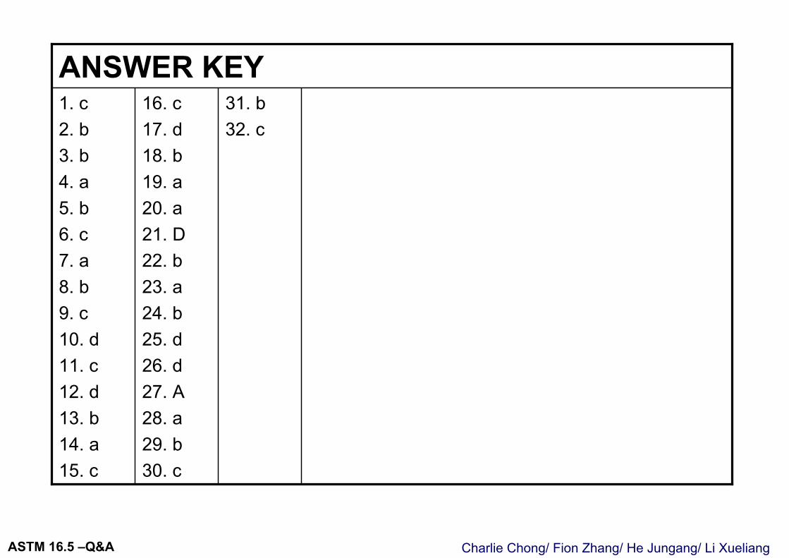
Charlie Chong/ Fion Zhang/ He Jungang/ Li XueliangASTM 16.5 –Q&A
16. c17. d18. b19. a20. a21. D22. b23. a24. b25. d26. d27. A28. a29. b30. c
1. c2. b3. b4. a5. b6. c7. a8. b9. c10. d11. c12. d13. b14. a15. c
31. b32. c
ANSWER KEY
Charlie Chong/ Fion Zhang/ He Jungang/ Li XueliangASTM 16.5 –Q&A
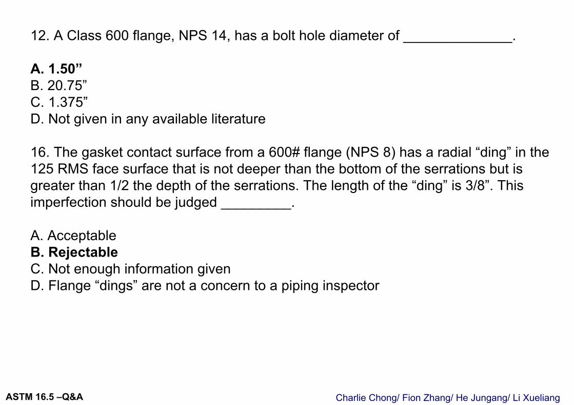
Charlie Chong/ Fion Zhang/ He Jungang/ Li XueliangASTM 16.5 –Q&A
12. A Class 600 flange, NPS 14, has a bolt hole diameter of ______________.
A. 1.50”B. 20.75”C. 1.375”D. Not given in any available literature
16. The gasket contact surface from a 600# flange (NPS 8) has a radial “ding” in the 125 RMS face surface that is not deeper than the bottom of the serrations but is greater than 1/2 the depth of the serrations. The length of the “ding” is 3/8”. This imperfection should be judged _________.
A. AcceptableB. RejectableC. Not enough information givenD. Flange “dings” are not a concern to a piping inspector
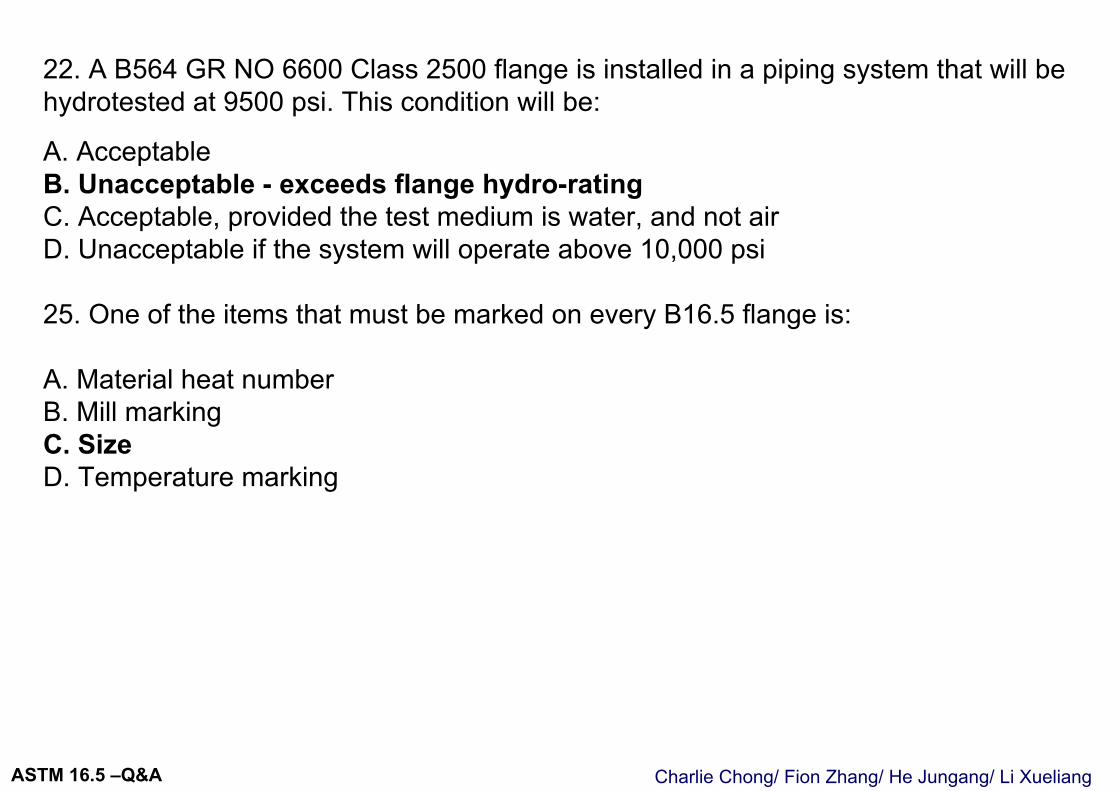
Charlie Chong/ Fion Zhang/ He Jungang/ Li XueliangASTM 16.5 –Q&A
22. A B564 GR NO 6600 Class 2500 flange is installed in a piping system that will be hydrotested at 9500 psi. This condition will be:
A. AcceptableB. Unacceptable - exceeds flange hydro-ratingC. Acceptable, provided the test medium is water, and not airD. Unacceptable if the system will operate above 10,000 psi
25. One of the items that must be marked on every B16.5 flange is:
A. Material heat numberB. Mill markingC. SizeD. Temperature marking
Charlie Chong/ Fion Zhang/ He Jungang/ Li XueliangASTM 16.5 –Q&A
134. Socket weld and threaded flanges are not recommended for service above ______oF or below _____ oF, per B16.5.
A. 500, -50B. 300, -20C. 200, -10D. 100, -5
150. Per ASME B16.5, bolt holes in flanges are all required to be placed in multiples of _______.
A. 2B. 3C. 6D. 4
Valentino
高亮

Charlie Chong/ Fion Zhang/ He Jungang/ Li XueliangASTM 16.5 –Q&A

Charlie Chong/ Fion Zhang/ He Jungang/ Li XueliangASTM 16.5 -7

Charlie Chong/ Fion Zhang/ He Jungang / Li Xueliang