
29 (n 1): 5 : Offline GATE Mock ‐6_Solutions ACE Engineering Academy...
16
ACE Engineering Academy Hyderabad|Delhi|Bhopal|Pune|Bhubaneswar| Lucknow|Patna|Bengaluru|Chennai|Vijayawada|Vizag |Tirupati | Kukatpally| Kolkata Offline GATE Mock -6 _ Solutions General Aptitude (GA) One Mark Solutions: 01. Ans: (A) 02. Ans: (C) 03. Ans: (D) Sol: Though most people disregarded or made fun of her book, some appreciated it. 04. Ans: (B) 05. Ans: (D) Sol: The sequence is a combination of two series; (I): 19, 38, 114, (----) and (II): 2, 3, 4 The pattern followed in (I) is 2, 3, ……. Missing number = 114 4 = 456 06. Ans: (B) Sol: 5 log 10 + 1 ) 5 x ( log ) 1 x 5 ( log 10 10 5 log 10 + 10 log ) 5 x ( log ) 1 x 5 ( log 10 10 10 )) 5 x ( 10 ( log ) 1 x 5 ( 5 ( log 10 10 5(5x+1) = 10(x+5) 25x+5 = 10x+50 15x = 45 x = 3 07. Ans: (A) Sol: LCM = 44 HCF l = 44H LCM + HCF = 1125 44 H + H = 1125 45H = 1125 L = 44 25 = 1100 a b = L H 25 b = 1100 25 b = 1100 08. Ans: (C) Sol: Both friends are coming to meet each other Distance travelled by them on first day = 20 + 10 = 30km Distance travelled by them on 2 nd day = 19+12 = 31km Distance travelled by them on third day = 18+14 = 32km So, he distances travelled by them for ms an A.P, with first term (A) = 30 and common difference (D) = 1 Let they meet after n days, then d ) 1 n ( 29 2 n S n
Transcript of 29 (n 1): 5 : Offline GATE Mock ‐6_Solutions ACE Engineering Academy...
ACE Engineering Academy Hyderabad|Delhi|Bhopal|Pune|Bhubaneswar| Lucknow|Patna|Bengaluru|Chennai|Vijayawada|Vizag |Tirupati | Kukatpally| Kolkata
Offline GATE Mock -6 _ Solutions
General Aptitude (GA)
One Mark Solutions:
01. Ans: (A)
02. Ans: (C)
03. Ans: (D)
Sol: Though most people disregarded or made fun
of her book, some appreciated it.
04. Ans: (B)
05. Ans: (D)
Sol: The sequence is a combination of two series;
(I): 19, 38, 114, (----) and (II): 2, 3, 4
The pattern followed in (I) is 2, 3, …….
Missing number = 114 4 = 456
06. Ans: (B)
Sol: 5log10 + 1)5x(log)1x5(log 1010
5log10 + 10log)5x(log)1x5(log 101010
))5x(10(log)1x5(5(log 1010
5(5x+1) = 10(x+5)
25x+5 = 10x+50
15x = 45
x = 3
07. Ans: (A)
Sol: LCM = 44 HCF l = 44H
LCM + HCF = 1125 44 H + H = 1125
45H = 1125
L = 44 25
= 1100
a b = L H
25 b = 1100 25
b = 1100
08. Ans: (C)
Sol: Both friends are coming to meet each other
Distance travelled by them on first day
= 20 + 10 = 30km
Distance travelled by them on 2nd day
= 19+12 = 31km
Distance travelled by them on third day
= 18+14 = 32km
So, he distances travelled by them for ms an
A.P, with first term (A) = 30 and common
difference (D) = 1
Let they meet after n days, then
d)1n(292
nSn
:2: EE‐GATE‐19
ACE Engineering Academy Hyderabad|Delhi|Bhopal|Pune|Bhubaneswar| Lucknow|Patna|Bengaluru|Chennai|Vijayawada|Vizag |Tirupati | Kukatpally| Kolkata
1)1n(3022
n385
)1n(602
n385
770 = n (59+n)
n2+ 59n– 770 =0
n2+ 70n–11n–770=0
n(n+70) –11(n+70)=0
(n-11) (n+70) =0
But n –70
Hence, they will meet after 11 days.
09. Ans: (D)
Sol: The total monthly budget of an average
household
= 4000+1200+2000+1500+1800
= Rs. 10500
Percentage of the monthly budget spent on
savings
= expensesTotal
amountsavings
%285.1410010500
1500
The approximate percentage of the
= 100 14.285 = 85.714 86%
monthly budget NOT spent on savings
10. Ans: (B)
Specific Section (EE)
One mark Solutions:
01. Ans: (A)
Sol: xydx
dy
xo = 0, yo = 1
x1 = xo + h = 0.1
x2 = xo + 2h = 0.2
ooo1 y,xfhyy
= 1 + (0.1) (1)
= 1.1
y2 = y1 + h f(x1 , y1)
= 1.1 + 0.1 [0.1 + 1.1]
= 1.1 + 0.12
= 1.22
02. Ans: (D)
Sol: To perform the given operation, both operands
must have same number of bits.
Hence by extending the sign bit, A = 111011
Now, A–B = 111011 – 100101
= 111011 + 2’s complement of
100101
= 111011 + 011011
(EAC – End Around Carry )
Hence A – B = 0 1 0 1 1 0
1 1 1 0 1 1 + 0 1 1 0 1 1 0 1 0 1 1 0 1
EAC is neglected in 2’s complement operation
:3: OfflineGATEMock‐6_Solutions
ACE Engineering Academy Hyderabad|Delhi|Bhopal|Pune|Bhubaneswar| Lucknow|Patna|Bengaluru|Chennai|Vijayawada|Vizag |Tirupati | Kukatpally| Kolkata
03. Ans: 2.121 (Range: 2 to 2.4)
Sol: f(x, y, z) = 2y + z
Directional derivate = a
a.pf
f f
f j ky z
= j .2 + 1.k
= kj2
Directional derivate = 2
kj.kj2
2
12
2
3
= 2.121
04. Ans: (A)
05. Ans: (B)
Sol: We have 0)0()(0
fxfLtx
f(x) is continuous at x = 0
h
fhfLtfh
)0()0()0(
0
00
1sin2
0
h
hh
Lth
f(x) is differentiable at x = 0
06. Ans: (B)
Sol: A ideal PMMC voltmeter will read average
voltage.
for 1-, half wave voltage controller, output
voltage, V0 = mVcos 1
2
= mV1 1
2
= mV
07. Ans: (B)
Sol: In figure ‘b’ all the three systems have the
identical damped frequency d
Peak time is same ,d
pt
08. Ans: (B)
Sol: The maximum reverse voltage across the
diode occurs when Vs is at its negative peak
and is equal to 24 + 12 = 36 V
The diode conducts only when Vs exceeds 12
V as shown below
The conduction angle is 2, where is given
by 24sin = 12
= sin–1(1/2) = 30o
Thus the conduction angle is 120o which
corresponds to one-third of a cycle
Hence the diode conducts for a duration of T/3
s during each cycle.
12V
24V
–2
Vs
iD iD
t
T
:4: EE‐GATE‐19
ACE Engineering Academy Hyderabad|Delhi|Bhopal|Pune|Bhubaneswar| Lucknow|Patna|Bengaluru|Chennai|Vijayawada|Vizag |Tirupati | Kukatpally| Kolkata
09. Ans: (C)
Sol: The load current referred to primary is 2A, and
the magnetizing current is 1A. These two have
a phase difference of 90 w.r.t each other.
Hence the primary current is )12( 22 =
2.24 A.
10. Ans: 50.24 (range 48 to 52)
Sol: Z = R+jL = 362 + j(100) 2
Z
Vi
6014.725
230
200j362
230
= 0.317–60
The current I = )60tsin(2317.0
Instantaneous voltage is maximum at 2
t
)6090sin(2317.0i
60cos2317.0i
= 0.224A
The energy stored = 21LI
2
212 (0.224) 50.2mJ
2
11. Ans: (B)
Sol: Let P be the input, Qn be present state and Qn+1
be next state.
R = nQP S = P Qn
Characteristic equation of SR flip-flop is
Qn+1 = S + nQR
= (P Qn) + nQP Qn
= (P Qn) + (P Qn) Qn
= (P Qn) (1 + Qn)
Qn+1 = P Qn
For P = 0, Qn+1 = Qn
For P = 1 Qn+1 = nQ
Hence the circuit functions as T flip-flop.
12. Ans: (B)
Sol: Inertia constant (H) =
salternatorofratingMVA
)MJ(rotorinstoredenergykinetic
4100
400H1 ; 6
150
900H2
21
21eq HH
HHH
=
64
64
= 2.4
13. Ans: (A)
Sol: Probability that there are exactly 2 defectives
in the first 5 selected articles = 12
5
C10
C7.C3
5
32
Probability that 6th article is defective =
5
1 Required probability =
12
1
5
1.
12
5
14. Ans: 11 (11 to 11)
Sol: The rms value of the square-wave voltage is
m
T
rms EdteT
E 0
21
And the average value is
m
T
av EdteT
E 2
0
.2
So that the form factor equals, by definition,
:5: OfflineGATEMock‐6_Solutions
ACE Engineering Academy Hyderabad|Delhi|Bhopal|Pune|Bhubaneswar| Lucknow|Patna|Bengaluru|Chennai|Vijayawada|Vizag |Tirupati | Kukatpally| Kolkata
1av
rms
E
Ek
The meter scale is calibrated in terms of the
rms value of a sine-wave voltage,
where Erms = k × Eav = 1.11Eav. For the square-
wave voltage, Erms = Eav, since k = 1.
Therefore the meter indication for the square-
wave voltage is high by a factor ksine wave/ksquare
wave = 1.11. The percentage error equals
1001
111.1
% = 11%.
15. Ans: 6
Sol: If the system has a non-zero solution then
determinant of coefficient matrix is zero.
0
132
213
321
(6 – ) ( 2 + 3 + 3) = 0
= 6
16. Ans: -10
Sol: 10100
k1
R
R
V
V
E
C
in
0
17. Ans: 0.02 (No range)
Sol: Hz/MW501
8025.1D
= 2 MW/Hz
= Hz/MWpu100
2
= 0.02 pu MW/Hz
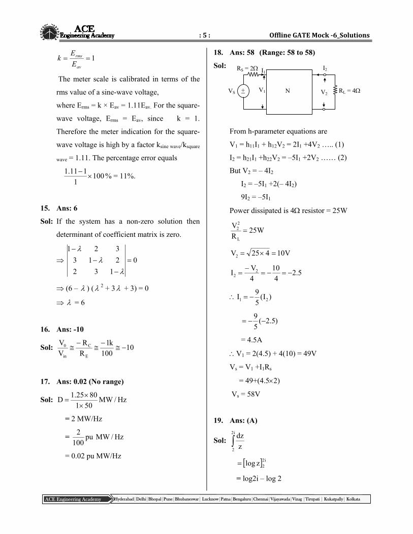
18. Ans: 58 (Range: 58 to 58)
Sol:
From h-parameter equations are
V1 = h11I1 + h12V2 = 2I1 +4V2 ….. (1)
I2 = h21I1 +h22V2 = –5I1 +2V2 …… (2)
But V2 = – 4I2
I2 = –5I1 +2(– 4I2)
9I2 = –5I1
Power dissipated is 4 resistor = 25W
W25R
V
L
22
V10425V2
5.24
10
4
VI 2
2
)I(5
9I 21
)5.2(5
9
= 4.5A
V1 = 2(4.5) + 4(10) = 49V
Vs = V1 +I1Rs
= 49+(4.52)
Vs = 58V
19. Ans: (A)
Sol: i2
2 z
dz
i22zlog
= log2i – log 2
V2
I2
VS + N RL = 4
RS = 2 I1
V1
:6: EE‐GATE‐19
ACE Engineering Academy Hyderabad|Delhi|Bhopal|Pune|Bhubaneswar| Lucknow|Patna|Bengaluru|Chennai|Vijayawada|Vizag |Tirupati | Kukatpally| Kolkata
= log 2 + log i – log 2
= log i
= 2
i
elog
2
i
20. Ans: (B)
Sol: Sending end voltage is given as
rrS BIAVV
Receiving end current under open condition is
zero
IR = 0
VS = AVR
VR = kV5008.0
400
A
VS
21 Ans: (A)
22. Ans: (D)
23. Ans: (C)
Sol: For ripple counter,
Maximum frequency of operation, f pdt.n
1
n number of flip-flops
tpd propagation delay of flip-flop
(12 × 106) 91012n
1
n 3101212
1
n 6.94
Always n is an integer n = 6
With n = 6, the modulus of counter = 2n
= 26
= 64
24. Ans: (d)
Sol: System is unstable, therefore error is
unbounded.
25. Ans: (B)
Sol: Deflection of electron beam on the screen in
y-direction, D = d d
a
Ll E
2dE m
Where L distance between the screen and
centre of the deflecting plates.
ld length of deflecting plates
Ed Potential between deflecting plates
d distance between deflecting plates.
Ea Pre-accelerating anode voltage
D d
a
E
E
D1 = d1
a1
E
E
D2 = d1
a1
2E1
E2
D2 = 4D1
D2 = 40 mm
Two marks Solutions:
26. Ans: 2
Sol: Since A is upper triangular matrix the eigen
values are same as the diagonal elements of A.
Eigen values are = 1, 1, 1
The eigen vectors for = 1 are given by
:7: OfflineGATEMock‐6_Solutions
ACE Engineering Academy Hyderabad|Delhi|Bhopal|Pune|Bhubaneswar| Lucknow|Patna|Bengaluru|Chennai|Vijayawada|Vizag |Tirupati | Kukatpally| Kolkata
[A – I] X = 0
0
0
0
z
y
x
000
000
010
Here rank of (A – I) = k = 1
Number of variables = n = 3
Number of linearly independent eigen vectors
= n – k = 2
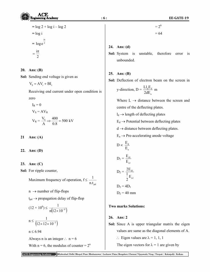
27. Ans: (D)
Sol: For the overall time constant of this circuit
input voltage source is short circuited
= Rth Ceq
= [10k||10k] 1 [1 + 99]
= [5k] 10–6 [102] = 0.5sec
28. Ans: (C)
Sol: )4s)(1s(
)3s)(2s(k)s(G
k 1
G(s) (s 2)(s 3)CLTF
1 G(s) (s 1)(s 4) (s 2)(s 3)
29. Ans: (B)
Sol: sec60
1
f
1TcycleonTurn
Rate of change of current
di
0.4dt
0.4 60 24A / sec
dt
diLVs
Source inductance L=24
240
dt
diVs
= 10 H
Circuit turn off time is given by
tc=R C ln2
21510-6 = 12Cln2
C = 3.6067F
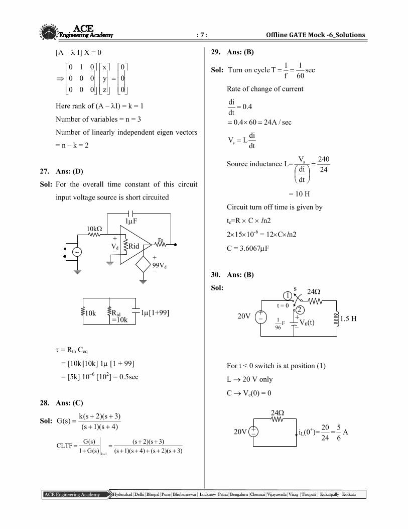
30. Ans: (B)
Sol:
For t < 0 switch is at position (1)
L 20 V only
C Vc(0) = 0
r0Rid
10k 1F
99Vd –
+
Vd –
+
Rid =10k
10k 1[1+99] 20V 1.5 H + –
24 s
t = 0
F96
1 + –
V0(t)
1
2
20V iL(0+)=24
20=
6
5A +
–
24
:8: EE‐GATE‐19
ACE Engineering Academy Hyderabad|Delhi|Bhopal|Pune|Bhubaneswar| Lucknow|Patna|Bengaluru|Chennai|Vijayawada|Vizag |Tirupati | Kukatpally| Kolkata
For t > 0 s is in position (2)
s
2
324
s
96)s(I
6
5
s
s5.1s2496)s(I
6
5 2
I(s) = )96s24s5.1(6
s52
s = )5.1(2
)96)(5.1(4)24(24 2
s = 3
57657624 = –8
s = –8
Roots are real & equal i(t) is critically
damped.
V0(t) = 22 )8s(
80
)8s(6
s5
s
96)s(I
s
96
V0(t) = (A + Bt)e–8t
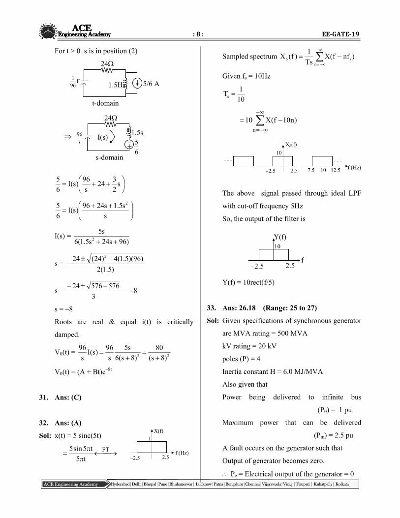
31. Ans: (C)
32. Ans: (A)
Sol: x(t) = 5 sinc(5t)
FT
t5
t5sin5
Sampled spectrum
ns )nff(X
Ts
1)f(X
Given fs = 10Hz
10
1Ts
n
)n10f(X10
The above signal passed through ideal LPF
with cut-off frequency 5Hz
So, the output of the filter is
Y(f) = 10rect(f/5)
33. Ans: 26.18 (Range: 25 to 27)
Sol: Given specifications of synchronous generator
are MVA rating = 500 MVA
kV rating = 20 kV
poles (P) = 4
Inertia constant H = 6.0 MJ/MVA
Also given that
Power being delivered to infinite bus
(P0) = 1 pu
Maximum power that can be delivered
(Pm) = 2.5 pu
A fault occurs on the generator such that
Output of generator becomes zero.
Pe = Electrical output of the generator = 0
–2.5 2.5
1 X(f)
f (Hz)
–2.5 2.5
10
X(f)
f (Hz) 7.5 12.5 10
f
Y(f)
–2.5 2.5
10
24
F96
1 1.5H 5/6 A
t-domain
24
s
96 I(s)
6
5
s-domain
1.5s – +
:9: OfflineGATEMock‐6_Solutions
ACE Engineering Academy Hyderabad|Delhi|Bhopal|Pune|Bhubaneswar| Lucknow|Patna|Bengaluru|Chennai|Vijayawada|Vizag |Tirupati | Kukatpally| Kolkata
Pe = 0
Pm = Mechanical input to the generator = 1 pu
Pa = Pm – Pe = 1 – 0 = 1pu
Pa = 1pu
Pa = Accelerating power
Angular acceleration is given by
M
P
dt
d a2
2
M = angular momentum
M = f
GH
MJ-sec/rad
In pu terms
M = f
H
MJ-sec/rad
H
f
dt
d2
2
[Pa = 1 pu]
6
5014.3
dt
d2
2
2
2
dt
d = 26.18 rad/sec2
34. Ans: 0.535 (Range: 0.5 to 0.6)
Sol: G(s)H(s) = K(s 4)
s(s 1)
For break in/away points dK
ds= 0
s(s+1) (s+4)(2s+1) = 0
s2 + s = 2s2 + 9s + 4
s = 8 64 16
2
s1 = 4 + 3.464, s2 = 4 3.464
s1 = 0.535, s2 = 7.464
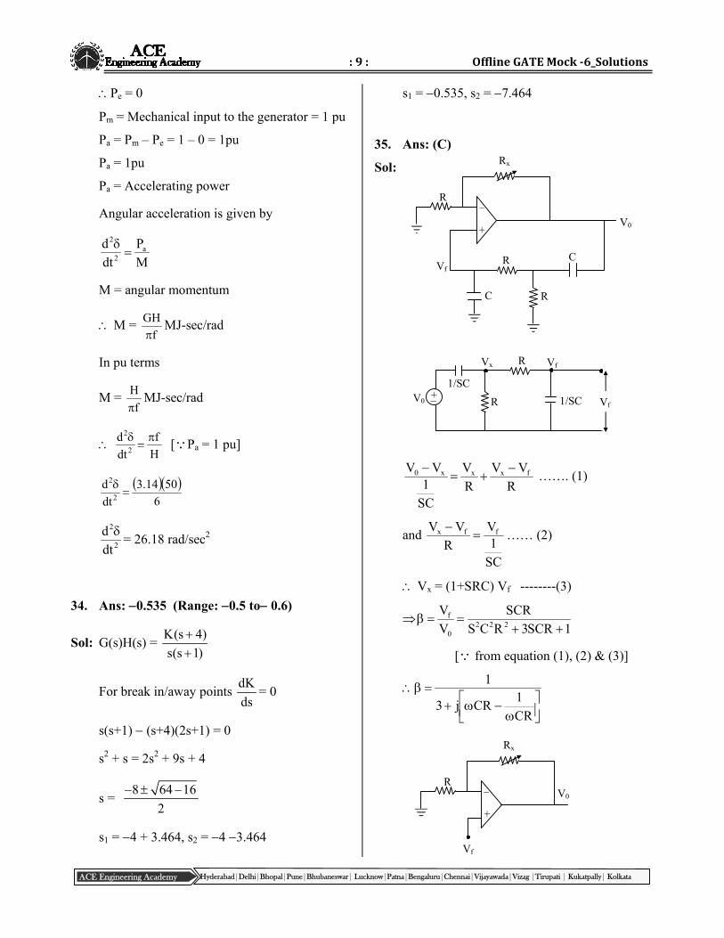
35. Ans: (C)
Sol:
R
VV
R
V
SC
1VV fxxx0
……. (1)
and
SC
1V
R
VV ffx
…… (2)
Vx = (1+SRC) Vf --------(3)
1SCR3RCS
SCR
V
V222
0
f
[ from equation (1), (2) & (3)]
CR
1CRj3
1
Rx
R
R C
+
–
C R
V0
Vf
Rx
R – V0
+
Vf
R
R
Vx
V0
Vf
Vf 1/SC
1/SC +–

:10: EE‐GATE‐19
ACE Engineering Academy Hyderabad|Delhi|Bhopal|Pune|Bhubaneswar| Lucknow|Patna|Bengaluru|Chennai|Vijayawada|Vizag |Tirupati | Kukatpally| Kolkata
R
R1
V
V x
f
0
Since for sustained oscillations A = 1
1
A
CR
1CRj3
R
R1 x
Equating img., parts
0CR
1CR
HzRC2
1f
& 3R
R1 x
Rx = 2R
36. Ans: (B)
Sol: From fig. by symmetry only the z-components
of the field exists along the z-axis.
dQ = s r dr d
R
zcos , 22 zrR
Hence
cosR4
dQdE
2o
Z
2222o
s
zr
z.
zr4
drdr
2/3229
6
zr1036
14
zrdrdr
10100
At z = 10 m
2
1r
2
0 2
32
6Z
)100r(
drd109E
2
1r2/32
6
100r
dr1018
2
1r2
6
100r100
r1018
= 54.63 kV/m
37. Ans: (B)
Sol: In case of motor
V = Eb +IaRa
Eb = V –IaRa
At 900 rpm
Eb= 60 –(300.35)
= 60 – 10.5 = 49.5
The back emf corresponding to speed of
300rpm is
Eb N
1
21b2b N
NEE
b2E300
49.5900
= 16.5V
V = b2E +IaRa
= 16.5 + (300.35) = 27
For a chopper V0 = DV
z
dE z
r Y
X
dQ = s rdr d
R
:11: OfflineGATEMock‐6_Solutions
ACE Engineering Academy Hyderabad|Delhi|Bhopal|Pune|Bhubaneswar| Lucknow|Patna|Bengaluru|Chennai|Vijayawada|Vizag |Tirupati | Kukatpally| Kolkata
1 k
1 k 1 k
1 k
VCC =5V
SW 2 SW 1 P
Q
R
27 = D60
D = 0.45
38. Ans: (B)
Sol: hc(n)=h1(n)*h2(n)=[(n+1)–(n)]*[(n) –(n–1)]
= (n+1)–2(n)+(n–1)
1,2,1
hc(n) 0, n<0
so,non causal
nc )n(h , stable
39. Ans: 2.28 (Range 2 to 2.5)
Sol: The phase voltage = 3
V LL V2303
398
Z1 = 20+ j37.7
7.37j20
230
Z
VI
1
11
= 5.39 –62.05
= 2.52 – j4.76
The equivalent star impedance
1.53j103
ZZ 2
eg2
1.53j10
230
Z
VI
eg2
12
= 0.79+j4.19
So total current I = I1 +I2
= 2.52–j4.76+0.79+j4.19
= 3.31 – j 0.57
= 3.36 –9.8
The power P = 3 power per phase
= 32303.36cos(9.8)
= 2284.6W
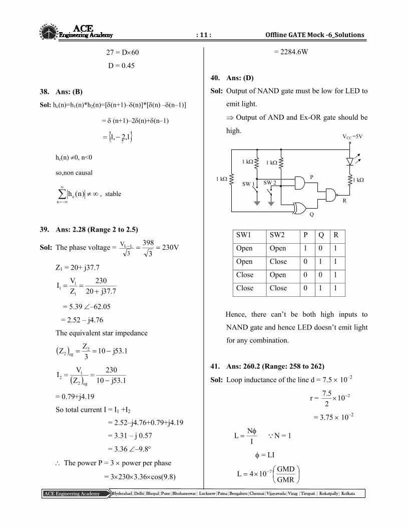
40. Ans: (D)
Sol: Output of NAND gate must be low for LED to
emit light.
Output of AND and Ex-OR gate should be
high.
SW1 SW2 P Q R
Open Open 1 0 1
Open Close 0 1 1
Close Open 0 0 1
Close Close 0 1 1
Hence, there can’t be both high inputs to
NAND gate and hence LED doesn’t emit light
for any combination.
41. Ans: 260.2 (Range: 258 to 262)
Sol: Loop inductance of the line d = 7.5 10–2
r = 2102
5.7
= 3.75 10–2
I
NL
N = 1
= LI
GMR
GMD104L 7
:12: EE‐GATE‐19
ACE Engineering Academy Hyderabad|Delhi|Bhopal|Pune|Bhubaneswar| Lucknow|Patna|Bengaluru|Chennai|Vijayawada|Vizag |Tirupati | Kukatpally| Kolkata
= 4 10–7 800 ln
21075.3
6.0
= 8.87 10–4
Voltage induced in sheath
=
= 2f
= 314 8.87 10–4
= 0.2602 V
= 260.2 Volt/km
42. Ans: (D)
Sol: total losses = 3[0.01+0.02] = 0.09 pu
The current carried by each transformer in
open delta is 3 pu and core losses in each
transformer remain unchanged
Now Cu losses = 12.002.0322
Core losses = 2(0.01) = 0.02
Total losses = 0.02+0.12 = 0.14
0.14 0.09
% increase 100 55.56%0.09
43. Ans: (C)
Sol:
2
0
dxxsinixcos
xsinixcosxf
dxxsinixcos
xsinixcos
xsinixcos
xsinixcos2
o
dxxsinxcos
x2sinixsinxcos2
022
22
2
0
dxx2sinix2cos
2
02
x2cosi
2
x2sin
= 112
i
= i
44. Ans: (C)
Sol: when converter circuit is working in an
inverter mode,
V0 = –E0 +I0R
= –230+(252)
= – 180
sm0 0
3 L3Vcos I V
2 2
33 2 400 3 100 2 10 25
cos 1802 2
cos = – 0.63
= 129.7
m0
s
VI cos cos( )
2 L
)7.129cos(7.129cos1021002
400225 3
0.055 = cos(129.7) – cos(129.7+)
cos(129.7+) = 0.069
= 4.27
45. Ans: (B)
Sol: Eb = V–IaRa = 500–60(0.5) = 470V
e = EbIa
e
2 800470 60
60
e = 336.61Nm
New load torque = 2.5336.61 = 841.52Nm
:13: OfflineGATEMock‐6_Solutions
ACE Engineering Academy Hyderabad|Delhi|Bhopal|Pune|Bhubaneswar| Lucknow|Patna|Bengaluru|Chennai|Vijayawada|Vizag |Tirupati | Kukatpally| Kolkata
Torque developed by the set
60
4002I5.0I2502
52.841 aa
2aI –500Ia+35250=0
2
352504500500I
2
a
2
15.330500
Ia = 415(or) 84.92 A
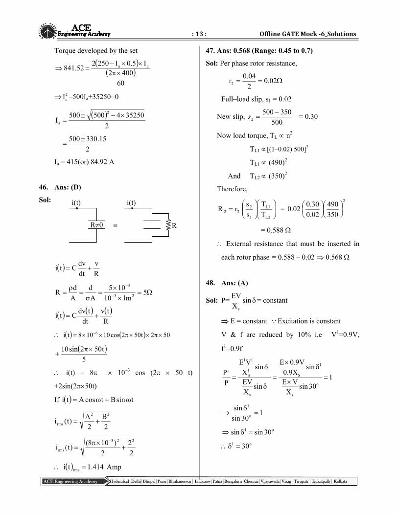
46. Ans: (D)
Sol:
R
v
dt
dvCti
5m110
105
A
d
A
dR
23
3
R
tv
dt
tdvCti
502t502cos10108ti 6
5
t502sin10
i(t) = 8 10–3 cos (2 50 t)
+2sin(250t)
If tsinBtcosAti
2
B
2
A)t(i
22
rms
2
2
2
)108()t(i
223
rms
414.1ti rms Amp
47. Ans: 0.568 (Range: 0.45 to 0.7)
Sol: Per phase rotor resistance,
02.02
04.0r2
Full–load slip, s1 = 0.02
New slip, 500
3505002
s = 0.30
Now load torque, TL n2
TL1 [(1–0.02) 500]2
TL1 (490)2
And TL2 (350)2
Therefore,
2L
1L
1
222 T
T
s
srR =
2
350
490
02.0
30.002.0
= 0.588
External resistance that must be inserted in
each rotor phase = 0.588 – 0.02 0.568
48. Ans: (A)
Sol: P= sinX
EV
s
= constant
E = constant Excitation is constant
V & f are reduced by 10% i,e V1=0.9V,
f1=0.9f
1
1 11 1
1S S
o
s s
E V E 0.9Vsin sin
X 0.9XP1
EV E VP sin sin 30X X
130sin
sino
1
o1 30sinsin
o1 30
R0
i(t) i(t)
R
:14: EE‐GATE‐19
ACE Engineering Academy Hyderabad|Delhi|Bhopal|Pune|Bhubaneswar| Lucknow|Patna|Bengaluru|Chennai|Vijayawada|Vizag |Tirupati | Kukatpally| Kolkata
–j2 j2 5
–j1
5
2 : 1
+ ~ –
–j2 j1
+ ~ –
2 : 1
10
2 : 1 –j2
+ ~ –
j2 3R
5
3X
–j2
~ –
2R
2X +
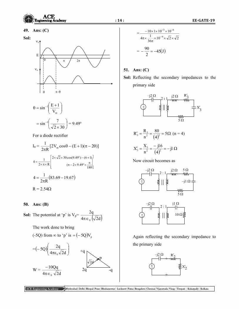
49. Ans: (C)
Sol:
m
1
V
1Esin
302
7sin 1 = 9.49
For a diode rectifier
I0 = )]2)(1E(cosV2[R2
1m
2 2 30cos(9.49 ) (6 1)1
42 R ( 2 9.49
180
67.1969.83R2
14
R = 2.54
50. Ans: (B)
Sol: The potential at ‘p’ is Vp= d24
q2
0
The work done to bring
(-5Q) from to ‘p’ is pVQ5
=
d24
q2Q5
0
W = d24
Qq10
0
=2210
36
14
1010110
9
63
= J452
90
51. Ans: (C)
Sol: Reflecting the secondary impedances to the
primary side
54
80
n
RR 22
33 (n = 4)
1j
4
16j
n
XX 22
33
Now circuit becomes as
Again reflecting the secondary impedance to
the primary side
2q
+q
p
-q
d2
–
2
s
o
E

:15: OfflineGATEMock‐6_Solutions
ACE Engineering Academy Hyderabad|Delhi|Bhopal|Pune|Bhubaneswar| Lucknow|Patna|Bengaluru|Chennai|Vijayawada|Vizag |Tirupati | Kukatpally| Kolkata
4j2/1
1j
n
1jX 222 (n=1/2)
402/1
10
n
10R 222
Total impedance seen by source
404j2jXR2jZ 22in
402j
52. Ans: 93.07 (92.5 to 94)
Sol: 15 KVA =iW2115
115
= 0.95
Wi = Wcu = 0.394Kw at ¾ load.
Copper loss at full
load = 2
40.394 0.7 kW
3
all –day
= 100)394.024()7.012()02012(
)02012(
= 93.07 %
53. Ans: (A)
Sol: The equivalent circuit shown below
Current IL = 136.86
=(0.8 + j0.6) pu
For the generator
gE = Vt + jIL dX
= 0.9 + (0.8 + j0.6) (j0.15)
= 0.81 + j0.12 pu
For motor
dLtm XjIVE
= 0.9 – (0.8 + j0.6) (j0.45)
= 1.17 – 0.36 pu
Sub transient current in the fault in the
generator
25.0j
12.0j81.0
X
EI
d
gg
= 0.48 – j3.24 pu
Sub transient current in the fault in the motor
35.0j
36.0j17.1
X
EI
d
mm
= –1.03 – j3.34 pu
54. Ans: (D)
Sol: G(s) = 2
5(1 0.1s)
s ss(1 0.5s) 1
50 0.65
Corner frequencies = 2, 10, 50 rad/s
The slope change at = 10 rad/sec is 40
dB/dec to 20 dB/dec
j0.10
j0.15
M
j0.35
F
2 10 50
60 dB/dec
20 dB/dec
40 dB/dec
20 dB/dec
|G(s)H(s)| dB
rad/s

:16: EE‐GATE‐19
ACE Engineering Academy Hyderabad|Delhi|Bhopal|Pune|Bhubaneswar| Lucknow|Patna|Bengaluru|Chennai|Vijayawada|Vizag |Tirupati | Kukatpally| Kolkata
55. Ans: (A)
Sol: tcosetcose2
1
2
)t(x)t(x)t(x t2t2
e
t2t2e eetcos
2
1)t(x
xe(t) = cosh(2t) cost