


Languages
Pages
Legal


82 Move-Tec Rodless style | Drive + Guide
Twin tube actuator - EP/EPX
Features: � Enables high moments
� Version available with large fixing plate
Options: � Corrosion-protected units
� Bellows
� Second not driven carriage
Large fixing plate 9The EPX version is equipped with
two carriages that are connected via a large fixing plate
9Enables high moments
Carriages available with optional slide bushing
9Lower input torque at shaft
9Wear minimised on carriage
Screw with choice of slide bearing or ball bearing
9Ideal for use in environments with fine dust/abraded particles due to slide bearings
The robust twin tube unit –compensates for high bending moments during hand and motor-driven adjustments
83Move-Tec
Mo
ve-T
ecPl
ace-
Tec
Co
ntr
ol-
Tec
Intr
od
uct
ion
Sele
ctio
n a
idA
pp
end
ixM
od
ule
sM
oto
rs/
Co
ntr
ols
Twin tube actuator - EP/EPX
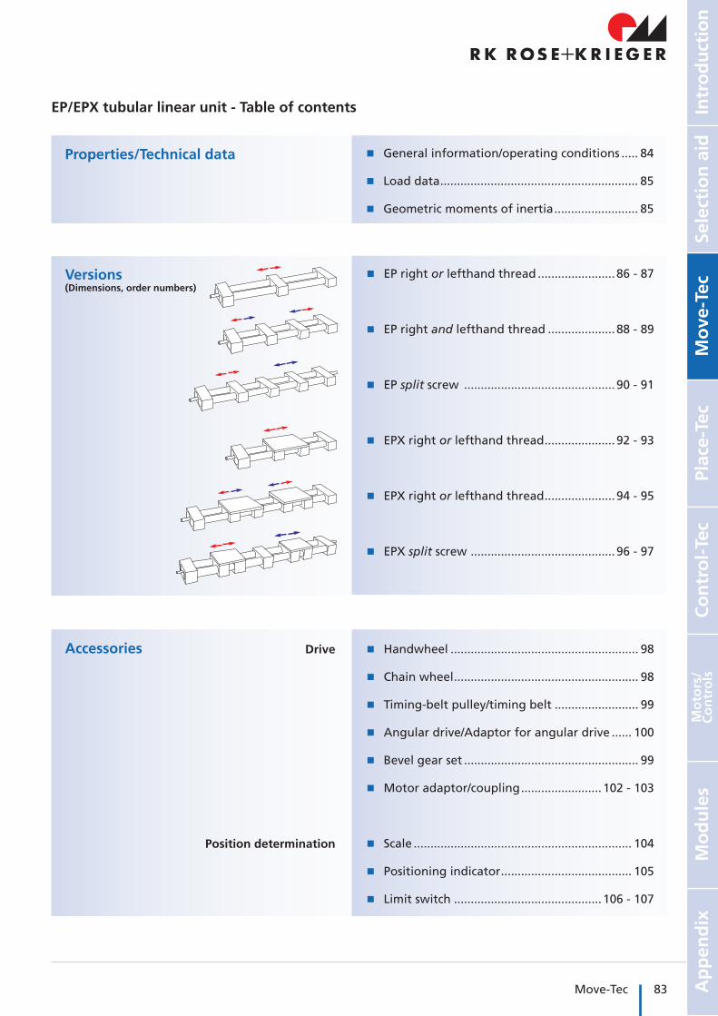
EP/EPX tubular linear unit - Table of contents
Properties/Technical data
Versions(Dimensions, order numbers)
Accessories
� General information/operating conditions ..... 84
� Load data ........................................................... 85
� Geometric moments of inertia ......................... 85
� EP right or lefthand thread ....................... 86 - 87
� EP right and lefthand thread .................... 88 - 89
� EP split screw ............................................. 90 - 91
� EPX right or lefthand thread ..................... 92 - 93
� EPX right or lefthand thread ..................... 94 - 95
� EPX split screw ........................................... 96 - 97
� Handwheel ........................................................ 98
� Chain wheel ....................................................... 98
� Timing-belt pulley/timing belt ......................... 99
� Angular drive/Adaptor for angular drive ...... 100
� Bevel gear set .................................................... 99
� Motor adaptor/coupling ........................ 102 - 103
� Scale ................................................................. 104
� Positioning indicator ....................................... 105
� Limit switch ............................................ 106 - 107
Drive
Position determination

84 Move-Tec Rodless style | Drive + Guide
General information/operating conditions
Design Twin tube actuator with ACME screw
Guide Slide guide, optional carriage with slide guide available
Installation position Any position
Lead accuracy ± 0.2 mm/300 mm stroke
Self-locking Yes
Ambient temperature 0°C to +60°C
Required screw speed* n [rpm] = speed [m/min] x 1000 screw lead [mm]
Max. screw speed with slide bearing 80 rpm with ball bearing 250 rpm
No-load torque
Type with ball bearing with slide bearing
EP 18 0.30 *
EP 30 0.60 0.75
EP 40 0.70 0.85
EP 50 1.10 1.25
EP 60 1.40 *
EP 80 1.00 *
Type with ball bearing with slide bearing
EPX 18 0.40 *
EPX 30 0.70 0.75
EPX 40 0.80 0.85
EPX 50 1.20 1.25
EPX 60 1.50 *
EPX 80 1.40 *
EP/EPX – Technical data
[mm]
[Nm] [Nm]
Screw lead
Type Screw lead [mm] Speed with slide bearing [mm/s] Speed with ball bearing [mm/s]
EP / EPX 18 2 2,7 8,3
EP / EPX 30 3 4 12,5
EP / EPX 40 4 5,3 16,7
EP / EPX 50 4 5,3 16,7
EP / EPX 60 5 6,7 20,8
EP / EPX 80 6 8 25
* Type 18, 60 and 80 spindle only available with ball bearing

85Move-Tec
Mo
ve-T
ecPl
ace-
Tec
Co
ntr
ol-
Tec
Intr
od
uct
ion
Sele
ctio
n a
idA
pp
end
ixM
od
ule
sM
oto
rs/
Co
ntr
ols
Load data*
F Force [N]
M Moment [Nm]
I Geometric moment of inertia [cm4]
* with reference to carriage (deflection of guide element f = 0.5 mm, static, end elements supported)
Geometric moment of inertia
Type Iy Iz
EP(X) 18 1.03 21.39
EP(X) 30 3.47 46.57
EP(X) 40 14.84 198.06
EP(X) 50 30.81 319.84
EP(X) 60 65.88 795.90
EP(X) 80 237.41 3168.98
Type Fx Fy FzMx My Mz
Total length [mm] 500 500 1000 1500 500 1000 1500
EP 18 400 200 100 – 100 70 – 20 30 35
EP 30 800 1000 800 500 550 300 100 60 60 75
EP 40 1000 3500 2600 1300 2000 580 120 120 130 150
EP 50 1700 3800 2300 2050 3000 670 170 160 200 260
EP 60 2500 6600 5400 4900 6000 2600 330 300 340 480
EP 80 4500 11000 9000 7500 8000 4800 700 400 530 620
EPX 18 400 270 170 – 130 100 – 40 45 70
EPX 30 800 1400 1200 700 650 450 200 80 110 140
EPX 40 1000 6000 3100 1800 2200 680 220 160 190 240
EPX 50 1700 7700 5000 2500 3300 830 310 240 345 510
EPX 60 2500 11000 9000 7800 7000 2900 580 520 610 910
EPX 80 4500 14000 11700 10100 9100 3700 750 650 780 1100
y
z
[cm4]
EP/EPX - Technical data

86 Move-Tec Rodless style | Drive + Guide
Version � Right or lefthand thread
Bearing:0 = spindle with slide bearing*1 = spindle with ball bearing2 = spindle with slide bearing* and carriage with slide bushing3 = spindle with ball bearing and carriage with slide bushing
Version:1 = righthand thread2 = lefthand thread
_ _ _ _ Total length = basic length + travel [mm]
Order information:
EP - Versions
Type 18-60(image similar)
Type 80
Code No. Type SpindleBasic
lengthB C D1 D2 D3 F G1** G2 H J L1 L2 M1 M2 M3 M4
72_181_ 18 10 x 2 104 85 29 6
–16 H7 1 – M5/5 deep 14.5 28 17
–– 68 40 18
72_183_ 6 17
72_301_ 30 14 x 3 150 130 54 8
–30 H8 2 M6/12
deep M6/9 deep 27 50 26
– 40 x 30
114 70 4272_303_ 8 26
72_401_ 40 20 x 4 180 180 63 12
–40 H8 3 M8/20
deep M8/8 deep 31.5 60 38
–46 160 90 62
72_403_ 12 38
72_501_ 50 20 x 4 216 206 73 12
–40 H8 2 M8/30
deep M8/8 deep 36.5 72 38
–46 184 100 62
72_503_ 12 38
72_601_ 60 24 x 5 240 240 88 14
–50 H8 2 M8/20
deep M10/10 deep 44 80 38
–55 216 130 74
72_603_ 14 38
72_801_ 80 32 x 6 360 302 143 20
–70 H7 4.5 M8/20
deep M10/20 deep 71.5 120 31.5
–64 – 180 –
72_803_ 20 31.5
* Type 18, 60 and 80 spindle only available with ball bearing** G1 thread only available on spindle with ball bearing
� Corrosion-protected units available on request
� Second free-running carriage available on request
� Bellows version available as optional extra

87Move-Tec
Mo
ve-T
ecPl
ace-
Tec
Co
ntr
ol-
Tec
Intr
od
uct
ion
Sele
ctio
n a
idA
pp
end
ixM
od
ule
sM
oto
rs/
Co
ntr
ols
Total length = basic length + travel
Total length - R
Total length
Only for EP18
M 5 M 6 M 7 M 8 O P 1 P 2 Q R W 1 W 2 W 3 W 4Max.travel
Mass [kg]
Basic length per 100 mm travel
– – – – 18 2 x 2 x 12–
28 28 5.5 A/F 8/6.5 deep – –
380 0.775 0.447
2 x 2 x 12 360 0.779 0.447
35 92 – – 30 2 x 2 x 20–
52 50 6.5 A/F 10/26.5 deep – –
1350 2.065 0.330
2 x 2 x 20 1290 2.075 0.330
38 132 – – 40 4 x 4 x 32–
60 60 8.5 A/F 13/32 deep 6.5 11/7
deep
2760 4.925 0.900
4 x 4 x 32 2700 4.960 0.900
50 150 – – 50 4 x 4 x 32–
72 72 8.5 A/F 13/37.5 deep 8.5
A/F 13/8.5 deep
2750 7.438 1.100
4 x 4 x 32 2700 7.473 1.100
60 185 – – 60 5 x 5 x 32–
86 80 10.5 A/F 17/44.5 deep 8.5
A/F 13/8.5 deep
2690 13.420 1.630
5 x 5 x 32 2650 13.466 1.630
– – 80 180 80 6 x 6 x 22–
138.5 – – – – –2600 35.920 3.470
6 x 6 x 22 2600 36.010 3.470
[mm]
EP - Versions

88 Move-Tec Rodless style | Drive + Guide
Version � Right and lefthand threadOrder information:
EP - Versions
Type 18-60(image similar)
Type 80
Lefthand thread (shaft end L1)
Righthand thread
Code No. Type SpindleBasic
lengthB C D 1 D 2 D 3 F G 1** G 2 H J L 1 L 2 M 1 M 2 M 3 M 4
72318_ _ 18 10 x 2 132 85 29 6 6 16H7 1 –M5/5 deep 14.5 28 17 17 – 68 40 18
72330_ _ 30 14 x 3 200 130 54 8 8 30H8 2 M6/12 deep
M6/9 deep 27 50 26 26 40 x
30 114 70 42
72340_ _ 40 20 x 4 240 180 63 12 12 40H8 3 M8/20 deep
M8/8 deep 31.5 60 38 38 46 160 90 62
72350_ _ 50 20 x 4 288 206 73 12 12 40H8 2 M8/30 deep
M8/8 deep 36.5 72 38 38 46 184 100 62
72360_ _ 60 24 x 5 320 240 88 14 14 50H8 2 M8/20 deep
M10/20 deep 44 80 38 38 55 216 130 74
72380_ _ 80 32 x 6 480 302 143 20 20 70H7 4.5 M8/20 deep
M10/20 deep 71.5 120 31.5 31.5 64 – 180 180
Bearing:0 = spindle with slide bearing*1 = spindle with ball bearing2 = spindle with slide bearing* and carriage with slide bushing3 = spindle with ball bearing and carriage with slide bushing
Version:1 = 1 drive shaft at lefthand thread end2 = 1 drive shaft at righthand thread end3 = 2 drive shafts
_ _ _ _ Total length = basic length + total travel [mm]
* Type 18, 60 and 80 spindle only available with ball bearing** G1 thread only available on spindle with ball bearing
� Please specify total travel when placing an order
� Corrosion protected units available on request
� Second free running carriage available on request
� Bellows version available as optional extra

89Move-Tec
Mo
ve-T
ecPl
ace-
Tec
Co
ntr
ol-
Tec
Intr
od
uct
ion
Sele
ctio
n a
idA
pp
end
ixM
od
ule
sM
oto
rs/
Co
ntr
ols
Total length = basic length + travel
Total length - R
Total length
Only for EP18
M 5 M 6 M 7 M 8 O P 1 P 2 Q R W 1 W 2 W 3 W 4Max. travel
Mass [kg]
Basic length per 100 mm travel
– – – – 18 2 x 2 x 12 2 x 2 x 12 28 28 5.5 A/F 8/6.5 deep – – 350 1.014 0.447
35 92 – – 30 2 x 2 x 20 2 x 2 x 20 52 50 6.5 A/F 1026.5 deep – – 1270 2.440 0.330
38 132 – – 40 4 x 4 x 32 4 x 4 x 32 60 60 8.5 A/F 1332 deep 6.5 11/
7 deep 2720 5.585 0.900
50 150 – – 50 4 x 4 x 32 4 x 4 x 32 72 72 8.5 A/F 1337.5 deep 8.5 A/F 13
8.5 deep 2670 8.633 1.100
60 185 – – 60 5 x 5 x 32 5 x 5 x 32 86 80 10.5 A/F 1744.5 deep 8.5 A/F 13
8.5 deep 2640 18.182 1.630
– – 80 180 80 6 x 6 x 22 6 x 6 x 22 138.5 120 – – – – 2450 48.480 3.470
[mm]
EP - Versions

90 Move-Tec Rodless style | Drive + Guide
Version � Split screw
EP - Versions
Type 18-60(image similar)
Type 80
Righthand thread
Righthand thread
Code No. Type SpindleBasic
lengthB C D 1 D 2 D 3 F G 1** G 2 H J L 1 L 2 M 1 M 2 M 3 M 4
724183 _ 18 10 x 2 160 85 29 6 6 16H7 1 – M5/5 deep 14.5 28 17 17 – 68 40 18
724303 _ 30 14 x 3 250 130 54 8 8 30H8 2 M6/12 deep
M6/9 deep 27 50 26 26 40 x 30 114 70 42
724403 _ 40 20 x 4 300 180 63 12 12 40H8 3 M8/20 deep
M8/8 deep 31.5 60 38 38 46 160 90 62
724503 _ 50 20 x 4 360 206 73 12 12 40H8 2 M8/30 deep
M8/8 deep 36.5 72 38 38 46 184 100 62
724603 _ 60 24 x 5 400 240 88 14 14 50H8 2 M8/20 deep
M10/10 deep 44 80 38 38 55 216 130 74
724803 _ 80 32 x 6 600 302 143 20 20 70H7 4.5 M8/20 deep
M10/20 deep 71.5 120 31.5 31.5 64 – 180 180
Bearing:1 = spindle with ball bearing and carriage without slide bushing3 = spindle with ball bearing and carriage with slide bushing
_ _ _ _ Total length = basic length + total travel [mm]
Order information:
� Please specify total travel when placing an order
� Corrosion-protected units available on request
� Second free-running carriage available on request
� Bellows version available as optional

91Move-Tec
Mo
ve-T
ecPl
ace-
Tec
Co
ntr
ol-
Tec
Intr
od
uct
ion
Sele
ctio
n a
idA
pp
end
ixM
od
ule
sM
oto
rs/
Co
ntr
ols
Total length = basic length + travel
Total length - R
Total length
Only for EP18
M 5 M 6 M 7 M 8 O P 1 P 2 Q R W 1 W 2 W 3 W 4Max.
travel/endMass [kg]
Basic length per 100 mm travel
– – – – 18 2 x 2 x 12 2 x 2 x 12 28 28 5.5 A/F 8/6.5 deep – – 400 1.240 0.447
35 92 – – 30 2 x 2 x 20 2 x 2 x 20 52 50 6.5 A/F 10/26.5 deep – – 1340 2.645 0.330
38 132 – – 40 4 x 4 x 32 4 x 4 x 32 60 60 8.5 A/F 13/32 deep 6.5 11/7 deep 2000 8.020 0.900
50 150 – – 50 4 x 4 x 32 4 x 4 x 32 72 72 8.5 A/F 13/37.5 deep 8.5 A/F 13/8.5
deep 2000 12.760 1.100
60 185 – – 60 5 x 5 x 32 5 x 5 x 32 86 80 10.5 A/F 17/44.5 deep 8.5 A/F 13/8.5
deep 2000 22.532 1.630
– – 80 180 80 6 x 6 x 20 6 x 6 x 20 138.5 120 – – – – 1700 60.110 3.470
[mm]
EP - Versions

92 Move-Tec Rodless style | Drive + Guide
Version � Right or lefthand thread
EPX - Versions
Code No. Type SpindleBasic
lengthB C D 1 D 2 D 3 F G 1** G 2 G 3 H 1 H 2 J L 1 L 2 M 1 M 2 M 3 M 4
72 _ 181 _ 1810 x 2 156 85 37 6
–16H7 1 – M6 M5/5 deep 14.5 8 80 17
–– 68 40 18
72 _ 183 _ 18 6 17
72 _ 301 _ 3014 x 3 230 130 64 8
–30H8 2 M6/12
deep M6 M6/9 deep 27 10 130 26–
40 x 30 114 70 4272 _ 303 _ 30 8 26
72 _ 401 _ 4020 x 4 300 180 75 12
–40H8 3 M8/20
deep M8 M8/8 deep 31.5 12 180 38–
46 160 90 6272 _ 403 _ 40 12 38
72 _ 501 _ 5020 x 4 350 206 88 12
–40H8 2 M8/30
deep M8 M8/8 deep 36.5 15 206 38–
46 184 100 6272 _ 503 _ 50 12 38
72 _ 601 _ 6024 x 5 400 240 103 14
–50H8 2 M8/20
deep M10 M10/10 deep 44 15 240 38
–55 216 130 74
72 _ 603 _ 60 14 38
72 _ 801 _ 8032 x 6 550 302 162 20
–70H7 4.5 M8/20
deep M10 M10/20 deep 71.5 19 310 31.5
–64 – 180 180
72 _ 803 _ 80 20 31.5
Type 18-60(image similar)
Type 80
Bearing:0 = spindle with slide bearing*1 = spindle with ball bearing2 = spindle with slide bearing* and carriage with slide bushing 3 = spindle with ball bearing and carriage with slide bushing
Version:5 = righthand thread6 = lefthand thread
_ _ _ _ Total length = basic length + travel [mm]
* Type 18, 60 and 80 spindle only available with ball bearing** G1 thread only available on spindle with ball bearing
Order information:
� Corrosion-protected units available on request
� Second free-running carriage available on request
� Bellows version available as optional

93Move-Tec
Mo
ve-T
ecPl
ace-
Tec
Co
ntr
ol-
Tec
Intr
od
uct
ion
Sele
ctio
n a
idA
pp
end
ixM
od
ule
sM
oto
rs/
Co
ntr
ols
Total length = basic length + travel
Total length - R
Total length
Only for EPX18
M 5 M 6 M 7 M 8 M 9 M 10 O P 1 P 2 Q R W 1 W 2 W 3 W 4Max. travel
Mass [kg]
Basic length per 100 mm travel
– – 56 28 – – 18 2 x 2 x 12–
28 28 5.5 A/F 8/6.5 deep – –
320 1.261 0.447
2 x 2 x 12 310 1.265 0.447
35 92 80 114 – – 30 2 x 2 x 20–
52 50 6.5A/F
10/26.5 deep
– –1240 3.519 0.330
2 x 2 x 20 1210 3.529 0.330
38 132 120 160 – – 40 4 x 4 x 32–
60 60 8.5 A/F 13/32 deep 6.5 11/7
deep
2660 8.105 0.900
4 x 4 x 32 2620 8.140 0.900
50 150 134 184 – – 50 4 x 4 x 32–
72 72 8.5A/F
13/37.5 deep
8.5A/F
13/8.5 deep
2610 12.525 1.100
4 x 4 x 32 2570 12.560 1.100
60 185 160 216 – – 60 5 x 5 x 32–
86 80 10.5A/F
17/44.5 deep
8.5A/F
13/8.5 deep
2560 21.426 1.630
5 x 5 x 32 2520 21.472 1.630
– – 250 270 80 180 80 6 x 6 x 20– 138.5 120 – – – – 2340 54.760 3.470
6 x 6 x 20 2340 54.860 3.470
[mm]
EPX - Versions

94 Move-Tec Rodless style | Drive + Guide
Version � Right and lefthand thread
EPX - Versions
Type 18-60(image similar)
Type 80
Lefthand thread (shaft end L1)
Righthand thread
Code No. Type SpindleBasic
lengthB C D 1 D 2 D 3 F G 1** G 2 G 3 H 1 H 2 J L 1 L 2 M 1 M 2 M 3 M 4
72718_ _ 18 10 x 2 236 85 37 6 6 16H7 1 – M6 M5/5 deep 14.5 8 80 17 17 – 68 40 18
72730_ _ 30 14 x 3 360 130 64 8 8 30H8 2 M6/12 deep M6 M6/9
deep 27 10 130 26 26 40 x 30 114 70 42
72740_ _ 40 20 x 4 480 180 75 12 12 40H8 3 M8/20 deep M8 M8/8
deep 31.5 12 180 38 38 46 160 90 62
72750_ _ 50 20 x 4 556 206 88 12 12 40H8 2 M8/30 deep M8 M8/8
deep 36.5 15 206 38 38 46 184 100 62
72760_ _ 60 24 x 5 640 240 103 14 14 50H8 2 M8/20 deep M10 M10/10
deep 44 15 240 38 38 55 216 130 74
72780_ _ 80 32 x 6 860 302 162 20 20 70H7 4.5 M8/20 deep M10 M10/20
deep 71.5 19 310 31.5 31.5 64 – 180 180
Bearing:0 = spindle with slide bearing*1 = spindle with ball bearing2 = spindle with slide bearing* and carriage with slide bushing 3 = spindle with ball bearing and carriage with slide bushing
Version:1 = 1 drive shaft at lefthand thread end2 = 1 drive shaft at righthand thread end3 = 2 drive shafts
_ _ _ _ Total length = basic length + total travel [mm]
* Type 18, 60 and 80 spindle only available with ball bearing** G1 thread only available on spindle with ball bearing
Order information:
� Please specify total travel when placing an order
� Corrosion-protected units available on request
� Second free-running carriage available on request
� Bellows version available as optional

95Move-Tec
Mo
ve-T
ecPl
ace-
Tec
Co
ntr
ol-
Tec
Intr
od
uct
ion
Sele
ctio
n a
idA
pp
end
ixM
od
ule
sM
oto
rs/
Co
ntr
ols
Total length = basic length + travel
Total length - R
Total length
Only for EPX18
M 5 M 6 M 7 M 8 M 9 M 10 O P 1 P 2 Q R W 1 W 2 W 3 W 4Max. travel
Mass [kg]
Basic lengthper 100 mm
travel
– – 56 28 – – 18 2 x 2 x 12 2 x 2 x 12 28 28 5.5 A/F 8/6.5 deep – – 230 1.983 0.447
35 92 80 114 – – 30 2 x 2 x 20 2 x 2 x 20 52 50 6.5 A/F 10/26.5 deep – – 1080 5.588 0.330
38 132 120 160 – – 40 4 x 4 x 32 4 x 4 x 32 60 60 6.5 A/F 13/32 deep 6.5 11/7
deep 2440 13.030 0.900
50 150 134 184 – – 50 4 x 4 x 32 4 x 4 x 32 72 72 8.5 A/F 13/37.5 deep 8.5 A/F 13/8.5
deep 2360 20.166 1.100
60 185 160 216 – – 60 5 x 5 x 32 5 x 5 x 32 86 80 10.5 A/F 17/44.5 deep 8.5 A/F 13/8.5
deep 2280 34.244 1.630
– – 250 270 80 180 80 6 x 6 x 20 6 x 6 x 20 138.5 120 – – – – 2070 86.070 3.470
[mm]
EPX - Versions

96 Move-Tec Rodless style | Drive + Guide
Version � Split screw
EPX - Versions
Type 18-60(image similar)
Type 80
Righthand thread
Righthand thread
Code No. Type SpindleBasic
lengthB C D 1 D 2 D 3 F G 1** G 2 G 3 H 1 H 2 J L 1 L 2 M 1 M 2 M 3 M 4
728183_ 18 10 x 2 264 85 37 6 6 16H7 1 – M6 M5/5 deep 14.5 8 80 17 17 – 68 40 18
728303_ 30 14 x 3 410 130 64 8 8 30H8 2 M6/12 deep M6 M6/9
deep 27 10 130 26 26 40 x 30 114 70 42
728403_ 40 20 x 4 540 180 75 12 12 40H8 3 M8/20 deep M8 M8/8
deep 31.5 12 180 38 38 46 160 90 62
728503_ 50 20 x 4 628 206 88 12 12 40H8 2 M8/30 deep M8 M8/8
deep 36.5 15 206 38 38 46 184 100 62
728603_ 60 24 x 5 720 240 103 14 14 50H8 2 M8/20 deep M10 M10/10
deep 44 15 240 38 38 55 216 130 74
728803_ 80 32 x 6 980 302 162 20 20 70H7 4.5 M8/20 deep M10 M10/20
deep 71.5 19 310 31.5 31.5 64 – 180 180
Bearing:1 = spindle with ball bearing and carriage without slide bushing3 = spindle with ball bearing and carriage with slide bushing
_ _ _ _ Total length = basic length + total travel [mm]
Order information:
� Please specify total travel when placing an order
� Corrosion-protected units available on request
� Second free-running carriage available on request
� Bellows version available as optional

97Move-Tec
Mo
ve-T
ecPl
ace-
Tec
Co
ntr
ol-
Tec
Intr
od
uct
ion
Sele
ctio
n a
idA
pp
end
ixM
od
ule
sM
oto
rs/
Co
ntr
ols
Total length = basic length + travel
Total length - R
Total length
Only for EPX18
M 5 M 6 M 7 M 8 M 9 M 10 O P 1 P 2 Q R W 1 W 2 W 3 W 4Max.
travel/end
Mass [kg]
Basic length per 100 mm travel
– – 56 28 – – 18 2 x 2 x 12 2 x 2 x 12 28 28 5.5A/F
8/6.5 deep
– – 360 2.208 0.447
35 92 80 114 – – 30 2 x 2 x 20 2 x 2 x 20 52 50 6.5A/F
10/26.5 deep
– – 1260 6.247 0.330
38 132 120 160 – – 40 4 x 4 x 32 4 x 4 x 32 60 60 8.5A/F
13/32 deep
6.5 11/7 deep 2000 14.620 0.900
50 150 134 184 – – 50 4 x 4 x 32 4 x 4 x 32 72 72 8.5A/F
13/37.5 deep
8.5 A/F 13/8.5 deep 2000 22.608 1.100
60 185 160 216 – – 60 5 x 5 x 32 5 x 5 x 32 86 80 10.5A/F
17/44.5 deep
8.5 A/F 13/8.5 deep 2000 38.548 1.630
– – 250 270 80 180 80 6 x 6 x 20 6 x 6 x 20 138.5 120 – – – – 1510 97.700 3.470
[mm]
EPX - Versions

98 Move-Tec Rodless style | Drive + Guide
EP/EPX – Drive
Diam. 60-100 Diam. 140-200
Handwheel
[mm]
Material: Die-cast aluminium black powder-coating
Code No. TypeDiam.
AB C D E G P I
90901 18 60 6 18 13 16 22 2 x 2 28
90913 30 100 8 28 14 17 30 2 x 2 52
90915 40-50 100 12 28 14 17 30 4 x 4 52
90905 40-50 140 12 36 16.5 19.5 36 4 x 4 66
90906 60 140 14 36 16.5 19.5 36 5 x 5 66
90918 60 160 14 36 18 20 39 5 x 5 80
90929 80 200 20 42 20.5 24 45 6 x 6 80
Chain wheel
[mm]
� Other sizes on request Material: Steel 500 N/mm2, min.
Code No. Type A B C D E GNo. of teeth
Size
91703 30 8 M6 18 41.1 4.5 2 x 2 10 1/2 x 3/16"
91704 40 12 M6 20 53 4.5 4 x 4 13 1/2 x 3/16"
91705 50 12 M6 20 61 4.5 4 x 4 15 1/2 x 3/16"
91706 60 14 M6 25 85 4.5 5 x 5 21 1/2 x 3/16"
91708 80 20 M6 25 85 4.5 6 x 6 21 1/2 x 3/16"

99Move-Tec
Mo
ve-T
ecPl
ace-
Tec
Co
ntr
ol-
Tec
Intr
od
uct
ion
Sele
ctio
n a
idA
pp
end
ixM
od
ule
sM
oto
rs/
Co
ntr
ols
HTD timing-belt pulley
Timing-belt (endless)
[mm]
[mm]
� Suitable for maintenance-free continuous operation
� Excellent accuracy and zero backlash during change of direction
� Can be clamped on feather key
Material: Steel
Code No. Type A B C D E G Pull force Pitch
92103 30 8 23 20 19.09 14.5 2 x 2 220 N 5
92105 40/50 12 32 26 28.65 20.5 4 x 4 330 N 5
92106 60 14 32 26 28.65 20.5 5 x 5 330 N 5
92108 80 on request
� HTD timing-belt with steel insert � For pull force, see timing-belt pulley.
� Other lengths available on request.
Code No. Type A B C D Timing-belt length
92204 _ _ _ _ 30 3.81 1.75 5 9 305 550 750 1000
92205 _ _ _ _ 40/50/60 3.81 1.75 5 15 305 565 800 900
Timing-belt length [mm]
[mm]
Bevel gear set � Straight toothed
� Pressure angle 20°
Code No. Type A B C D E GNo. of teeth
Module
91603 Set 30 8 15 24 24 18 26.11 16 1.5
91623Single com-ponent 30
8 15 24 24 18 26.11 16 1.5
91604 Set 40 12 19 31 32 26 35 16 2
91664Single com-ponent 40
12 19 31 32 26 35 16 2
91605 Set 50 12 22 37 40 32 44 16 2.5
91625Single com-ponent 50
12 22 37 40 32 44 16 2.5
91606 Set 60 14 22 37 40 32 44 16 2.5
91666Single com-ponent 60
14 22 37 40 32 44 16 2.5
� Shaft angle 90°
� Crowned tooth flanks
EP/EPX - Drive

100 Move-Tec Rodless style | Drive + Guide
Angular drive
Adaptor for EP(X) angular drive
Code No. Type iMod-ule
No. of teeth
Diameter
B C E X
91523 30 1:1 1.5 16 8 96 42 75 43
91504 40 1:1 2 16 12 128 54 100 55
91555 50 1:1 2.5 16 12 148 65 115 68
91506 60 1:1 2.5 16 14 170 80 130 80
� If angular drives are fitted, the linear units are delivered exclu-sively with ball bearings
Scope of delivery: Housing, bevel gear set and transmission unit
Material: Angular drive housing made of die cast aluminiumSteel parts galvanisedPower transmission of bevel gears
[mm]
� Connection adaptor for mount-ing angular drives on EP units
� Spindle with special shaft re-quired
� If angular drives are fitted, the linear units are delivered exclu-sively with ball bearings
Material: AlMgSi, black anodised
Code No. Type A B C D E F G H I O
91533 30 30 40 50 50 22 30 30 5 55 6.6
91514 40 46 46 60 60 32 40 40 6 83 9
91525 50 46 46 60 60 32 40 50 6 93 9
91516 60 55 55 70 70 42 50 60 8 93 9
[mm]
EP/EPX – Drive

101Move-Tec
Mo
ve-T
ecPl
ace-
Tec
Co
ntr
ol-
Tec
Intr
od
uct
ion
Sele
ctio
n a
idA
pp
end
ixM
od
ule
sM
oto
rs/
Co
ntr
ols
TypeServomotor Three-phase motor
RK-AC 118 RK-AC 240RK-AC 240
with gear unitRK-AC 210/470
RK-AC 210/470 with gear unit
90/120 W 180/250 W
EP(X) 30949200 – – – – 949623 –
911430 0811
– – – –911940 0812
–
EP(X) 40949201 949221 949296 – – 949614 94914
911430 1112
911430 1214
911940 1220
– –911430 1212
911430 1214
EP(X) 50949202 949222 949297 – – 949614 949414
911430 1112
911430 1214
911940 1220
– –911430 1212
911430 1214
EP(X) 60949203 949223 949298 949239 949313 – 949616
911430 1114
911940 1414
911940 1420
911940 1419
912855 1425
–911940 1414
EP(X) 80949901 949903 949904 949905 949906 – 949909
911940 1120
9111940 1420
911940 2020
911940 1920
912855 2025
–911940 1420
Selection table - motor adaptor/coupling
Code No. Motor adaptor: 949903
Code No. Coupling with specification of shaft
diameter1st end = 14 mm
2nd end = 20 mm: 9111940 1420
Note: For further details on motor versions, please refer to the chapter “Motors and controls”
For dimensions and order data for motor adaptor and coupling, please refer to next page
EP/EPX - Drive

102 Move-Tec Rodless style | Drive + Guide
Code No. Type A B C D E F G
949200 30 64 53.5 53.5 60 53 70 M5
949247 30 66 53.5 53.5 73 70 90 M6
949275 30 71 53.5 53.5 60 53 70 M5
949623 30 64 53.5 53.5 50 65 80 M5
949201 40 74 60 60 60 53 70 M5
949276 40 83 60 60 60 53 70 M5
949221 40 83 60 60 80 70.7 90 M6
949296 40 100 60 60 80 70.7 90 M6
949248 40 83 60 60 73 70 90 M6
949614 40 83 60 60 50 46 80 M5
94914 40 83 60 60 80 100 Ø 120 Ø 6.6
949202 50 74 60 60 60 53 70 M5
949277 50 83 60 60 60 53 70 M5
949222 50 83 60 60 80 70.7 90 M6
949297 50 100 60 60 80 70.7 90 M6
949249 50 83 60 60 73 70 90 M6
949614 50 83 60 60 50 46 80 M5
949414 50 83 60 60 80 100 Ø 120 Ø 6.6
949203 60 74 80 80 60 53 70 M5
949278 60 86 80 80 60 53 70 M5
949223 60 86 80 80 80 70.7 90 M6
949298 60 102 80 80 80 70.7 90 M6
949239 60 96 80 80 95 81.3 115 M8
949313 60 112.5 80 80 110 91.9 115 M8
949250 60 81 80 80 73 70 90 M6
949616 60 86 80 80 80 100 Ø 120 Ø 6.6
949901 80 74 80 80 60 53 70 M5
949902 80 81 80 80 60 53 70 M5
949903 80 79 80 80 80 70.7 90 M6
949904 80 96 80 80 80 70.7 90 M6
949905 80 86 80 80 80 81.3 115 M8
949906 80 112.5 80 80 110 91.9 115 M8
949907 80 79 80 80 73 70 90 M6
949909 80 81 80 80 80 100 Ø 120 Ø 6.6
Motor adaptor � Simple assembly
� Exact fit due to centering shoul-ders
Material: Aluminium, black
[mm]
EP/EPX – Drive

103Move-Tec
Mo
ve-T
ecPl
ace-
Tec
Co
ntr
ol-
Tec
Intr
od
uct
ion
Sele
ctio
n a
idA
pp
end
ixM
od
ule
sM
oto
rs/
Co
ntr
ols
Coupling � Small size
� Shaft connection without back-lash
� Maintenance-free
� Easy plug-in assembly
Material: Hub – aluminiumSpider ring – polyurethane
To ensure the smooth running of the coupling, a clearance of D + 3 mm is required.
Code No. A B C D E PTorque [Nm]
with feather key
without feather key
9109200612 6 12 10 22 30 2 x 2/4 x 4 5 3
9109200895 8 9.5 10 20 30 2 x 2/– 5 3
9114300811 8 11 11 30 35 2 x 2/4 x 4 12 6
9114300816 8 16 11 30 35 2 x 2/5 x 5 12 6
9114309512 9.5 12 11 30 35 –/4 x 4 12 6
9114309514 9.5 14 11 30 35 –/5 x 5 12 6
9114301112 11 12 11 30 35 4 x 4/4 x 4 12 6
9114301114 11 14 11 30 35 4 x 4/5 x 5 12 6
9114301212 12 12 11 30 35 4 x 4/4 x 4 12 6
9114301214 12 14 11 30 35 4 x 4/5 x 5 12 6
9114301216 12 16 11 30 35 4 x 4/5 x 5 12 6
9119400812 08 12 25 40 65 2 x 2/4 x 4 17 10
9119401220 12 20 25 40 65 4 x 4/6 x 6 17 10
9119401414 14 14 25 40 65 5 x 5/5 x 5 17 10
9119401416 14 16 25 40 65 5 x 5/6 x 6 17 10
9119401419 14 19 25 40 65 5 x 5/6 x 6 17 10
9119401420 14 20 25 40 65 5 x 5/6 x 6 17 10
9119401620 16 20 25 40 65 6 x 6/6 x 6 17 10
9119401920 19 20 25 40 65 6 x 6/6 x 6 17 10
9119402020 20 20 25 40 65 6 x 6/6 x 6 17 10
9128551425 14 25 30 55 78 5 x 5/8 x 7 60 35
9128552025 20 25 30 55 78 6 x 6/8 x 7 60 35
[mm]
EP/EPX - Drive

104 Move-Tec Rodless style | Drive + Guide
EP/EPX – Position determination
Scale � Self-adhesive
� 4 mm high figures
Material: Steel band, plastic-coated
[mm]
Image shows scale to be read from left to right. Standard mounting at 0° (180° mounting of the left guiding tube, to be read from right to left)
* In the case of Type 18, a scale can be engraved in the guiding tube if required Please specify the position on the tube if relevant. Type 80 available on request
Scale
Code No. Type Can be read from Length B Version
92040 30* left to right 0-1000 8 fitted
92041
40-60*
right to left 0-1000 10 fitted
92042 left to right 0-1000 10 fitted
92045 left to right 0-2000 10 fitted
92046 right to left 0-2000 10 fitted

105Move-Tec
Mo
ve-T
ecPl
ace-
Tec
Co
ntr
ol-
Tec
Intr
od
uct
ion
Sele
ctio
n a
idA
pp
end
ixM
od
ule
sM
oto
rs/
Co
ntr
ols
Positioning indicator � Permitted ambient temperature +80°C
� Figure height 6 mm
� Indication accuracy ± 0.1 mm
� If positioning indicators are fitted, the linear units are delivered exclusively with ball bearings
Material: Housing polyamide 6Orange RAL 2004,Steel parts, corrosion-protected
Scope of delivery: Positioning indicator, clamping ring, shaft extension and fastenings
Note: “rising” and “falling” ver-sions refer to the clockwise rota-tion of the drive shaft.
Installation position: horizontal
Installation position: vertical
[mm]
* Version with double lead e.g. for installation on righthand/lefthand thread screws
TypeInstallation
positionCode No. Version Code No. Version* A B C D E F
18Horizontal
91061 2 mm rising 91012 4 mm rising 48 29 17 6 60 67
18 910712 mm falling
9101374 mm falling
48 29 17 6 60 67
18Vertical
91081 2 mm rising 910138 4 mm rising 48 29 17 6 60 67
18 910912 mm falling
9101394 mm falling
48 29 17 6 60 67
30Horizontal
91043 3 mm rising 91010 6 mm rising 48 25 26 8 59 67
30 91053 3 mm falling
91029 6 mm falling
48 25 26 8 59 67
30Vertical
91063 3 mm rising 91020 6 mm rising 48 25 26 8 59 67
30 910733 mm falling
910196 mm falling
48 25 26 8 59 67
40Horizontal
91004 4 mm rising 91030 8 mm rising 48 25 38 12 59 67
40 910144 mm falling
910398 mm falling
48 25 38 12 59 67
40Vertical
91024 4 mm rising 91040 8 mm rising 48 25 38 12 59 67
40 910344 mm falling
910418 mm falling
48 25 38 12 59 67
50Horizontal
91045 4 mm rising 91046 8 mm rising 48 25 38 12 59 75
50 910554 mm falling
910478 mm falling
48 25 38 12 59 75
50Vertical
91065 4 mm rising 91048 8 mm rising 48 25 38 12 59 75
50 910754 mm falling
910498 mm falling
48 25 38 12 59 75
60Horizontal
910120 5 mm rising 910124 10 mm rising 48 25 38 14 60 81
60 9101215 mm falling
91012510 mm falling
48 25 38 14 60 81
60Vertical
910122 5 mm rising 910126 10 mm rising 48 25 38 14 60 81
60 9101235 mm falling
91012710 mm falling
48 25 38 14 60 81
80Horizontal
91110 6 mm rising 910140 12 mm rising 64 29 31 20 60 94
80 911116 mm falling
91014112 mm falling
64 29 31 20 60 94
80Vertical
91112 6 mm rising 910142 12 mm rising 64 29 31 20 60 94
80 911136 mm falling
91014312 mm falling
64 29 31 20 60 94
EP/EXP - Position determination

106 Move-Tec Rodless style | Drive + Guide
Holder for mechanical limit switch
Mechanical limit switch
� Limit switch can be moved and fixed axially
Type 18-60 80
Max. voltage 250 V AC 230 V AC
Max. switching current 6 A 4 A
Max. starting current 16 A –
Operating frequency Max. 6000/h Max. 5000/h
Mechanical lifetime 10 million switching cycles 20 million switching cycles
Axis lever adjustment locking at 10° increments
Protection class IP 65 IP 67
Ambient temperature -30°C to +80°C
Code No. Type Basic length Version
92961_ _ _ _ 18-60 245 with switch
92962_ _ _ _ 18-60 245 without switch
92933_ _ _ _ 80 380 with switch
92934_ _ _ _ 80 380 without switch
Total length of linear unit
Type 18-60
Type 80
Square bar 10 mm
BLOCAN profile S-30 x 30
Movable clamping element
Code No. TypeSwitching function
A B C D
91905 18-60 NC/NO 26.5 45 45.5 21
91908 80 NC/NO 30 58.5 46 20
91907 Clamping element 18-60 for limit switch
91904 Clamping element 80 for limit switch
EP/EPX – Position determination
[mm]

107Move-Tec
Mo
ve-T
ecPl
ace-
Tec
Co
ntr
ol-
Tec
Intr
od
uct
ion
Sele
ctio
n a
idA
pp
end
ixM
od
ule
sM
oto
rs/
Co
ntr
ols
Holder for inductive limit switch
� Limit switch can be moved and fixed axially
Type 18-60 80
Voltage 10-30 V DC
Max. switching current 200 mA
Max. starting current 2 A for approx. 2 ms –
Operating frequency 700 Hz acc. to DIN EN 500101000 Hz acc. to DIN EN 50010
Mechanical lifetime independent of operating cycles
Operating distance 4 mm for steel 2 mm for steel
Protection class IP 67
Ambient temperature -25°C to +80°C
Code No. Type Basic length Version
92963_ _ _ _ 18-60 125 with NC contact
92964_ _ _ _ 18-60 125 with NO contact
92965_ _ _ _ 18-60 125 without switch
92930_ _ _ _ 80 336 with NC contact
92931_ _ _ _ 80 336 with NO contact
92932_ _ _ _ 80 336 without switch
Total length of linear unit
Inductive limit switch
Code No. TypeSwitching function
L MWrench
size
92805 18-60Normally
closed contact 37 12 x 1 18
92815 18-60Normally open
contact 37 12 x 1 18
92816 80Normally
closed contact 32 8 x 1 13
92817 80Normally open
contact32 8 x 1 13
92802 Clamping element 18-60 for limit switch
92804 Clamping element 80 for limit switch
Type 18-60
Type 80
Square bar 10 mm
BLOCAN profile S-30 x 30
Movable clamping element
[mm]
EP/EXP - Position determination
Top Related