


Languages
Pages
Legal

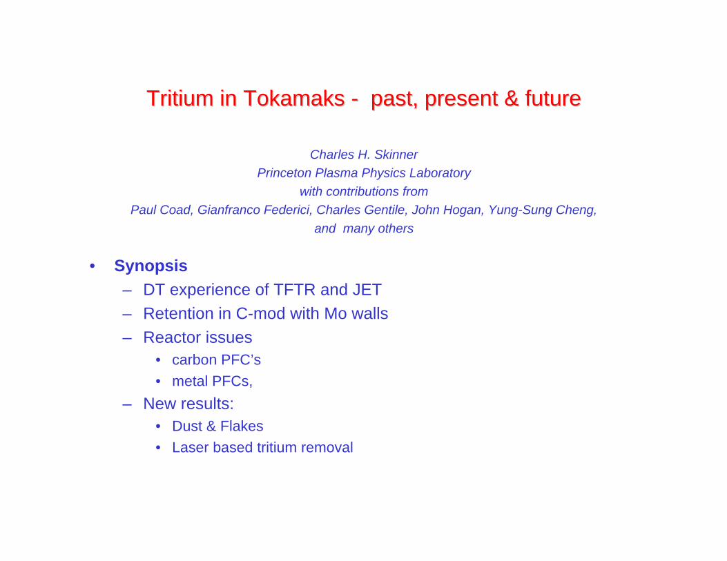
Tritium in Tritium in TokamaksTokamaks - past, present & future - past, present & future
Charles H. Skinner
Princeton Plasma Physics Laboratory
with contributions from
Paul Coad, Gianfranco Federici, Charles Gentile, John Hogan, Yung-Sung Cheng,
and many others
• Synopsis– DT experience of TFTR and JET– Retention in C-mod with Mo walls– Reactor issues
• carbon PFC’s
• metal PFCs,
– New results:• Dust & Flakes
• Laser based tritium removal

Tritium experience of TFTR & JETTritium experience of TFTR & JET
• TFTR• 10 MW fusion power• Limiter machine• typical SOL parameters• Ne ~ 0.1e19 - 1e19 m-3• Te ~ 200 eV - 600 eV
• JET• 16 MW fusion power• Divertor machine• typical divertor parameters• Ne ~ 10 e 19 m-3• Te ~ < 30 eV

TFTR fuel cycle:TFTR fuel cycle:
TFTR FUEL CYCLEN2 GLOVE BOX Ar GLOVE BOX
TORUS
GIAD2
NBINJECTORS
NBCRYO-
PANELS
TORUS CLEANUPSYSTEM
FUME HOOD
TVPS
DVS
MISC.IMPURITYSOURCES
DISPOSABLEMOLECULARSIEVE BED
(DMSB)
STACK
TRITIUMPRODUCT
CONTAINER(LP-50)
D2 SUPPLY
U-BEDS
TGIA
GASHOLDING
TANKS
BUBBLER
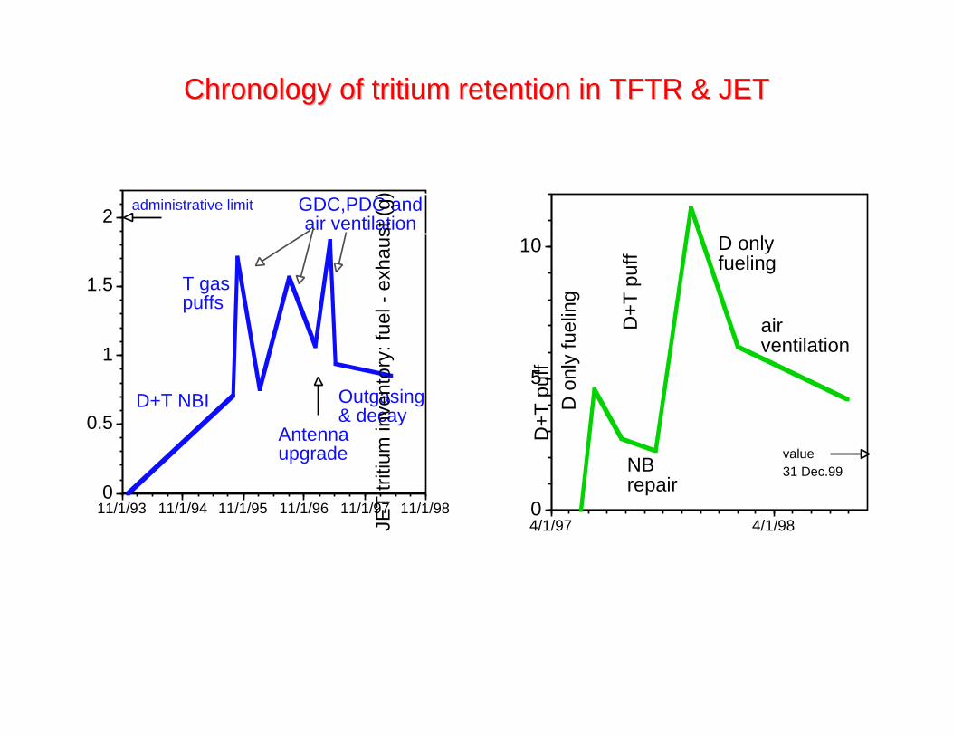
Chronology of tritium retention in TFTR & JETChronology of tritium retention in TFTR & JET
0
0.5
1
1.5
2
11/1/93 11/1/94 11/1/95 11/1/96 11/1/97 11/1/98 TF
TR
triti
um in
vent
ory:
fuel
- e
xhau
st (
g)
T gaspuffs
D+T NBI
GDC,PDC andair ventilation
Outgasing& decay
Antennaupgrade
administrative limit
0
5
10
4/1/97 4/1/98JET
triti
um in
vent
ory:
fuel
- e
xhau
st (
g)
NBrepair
D+
T p
uff
D+
T p
uff D only
fueling
airventilation
value31 Dec.99
D o
nly
fuel
ing
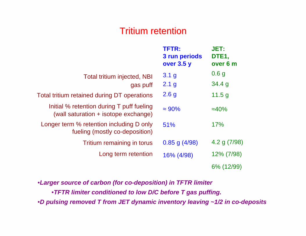
Tritium retentionTritium retention
JET:DTE1,over 6 m
0.6 g
34.4 g
11.5 g
≈40%
17%
4.2 g (7/98)
12% (7/98)
6% (12/99)
Total tritium injected, NBIgas puff
Total tritium retained during DT operations
Initial % retention during T puff fueling(wall saturation + isotope exchange)
Longer term % retention including D onlyfueling (mostly co-deposition)
Tritium remaining in torus
Long term retention
•Larger source of carbon (for co-deposition) in TFTR limiter
•TFTR limiter conditioned to low D/C before T gas puffing.
•D pulsing removed T from JET dynamic inventory leaving ~1/2 in co-deposits
TFTR:3 run periodsover 3.5 y
3.1 g2.1 g
2.6 g
≈ 90%
51%
0.85 g (4/98)
16% (4/98)

Location of Tritium in TFTRLocation of Tritium in TFTR
4.2 2.3
0.51
0.19
0.65
2.15
0.81
0.61 0.45 0.70 0.65
0.80
0.72
(0.16)(1.6)
(1.1)
(0.71)
Bay K
99E0014-04
1.0 CFC
graphite
Co-deposition, flaking,on bumper limiter at Bay K.
Tritium released (Ci) by 1 hour, 500Cbake of Bay K (L) tiles.
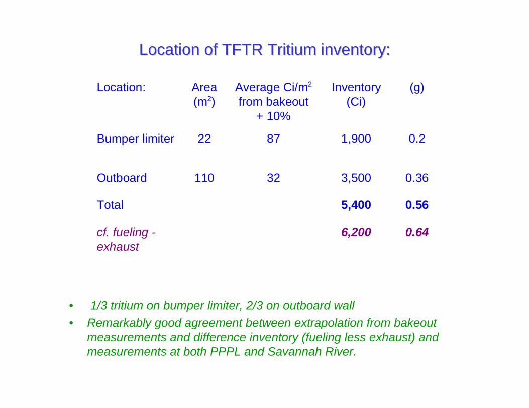
Location of TFTR Tritium inventory:Location of TFTR Tritium inventory:
Location: Area(m2)
Average Ci/m2
from bakeout+ 10%
Inventory(Ci)
(g)
Bumper limiter 22 87 1,900 0.2
Outboard 110 32 3,500 0.36
Total 5,400 0.56
cf. fueling -exhaust
6,200 0.64
• 1/3 tritium on bumper limiter, 2/3 on outboard wall
• Remarkably good agreement between extrapolation from bakeoutmeasurements and difference inventory (fueling less exhaust) andmeasurements at both PPPL and Savannah River.

Tritium retention in JET higher than expected Tritium retention in JET higher than expected
3.4 g tritium insub divertor ?
• Flakes seen on louvres in divertor.
•Tiles contain less tritium than expected.
• Tiles 3 & 4 showed unexpectedly high bulk tritium concentrations
• Remaining tritium believed to be in flakes in sub-divertor
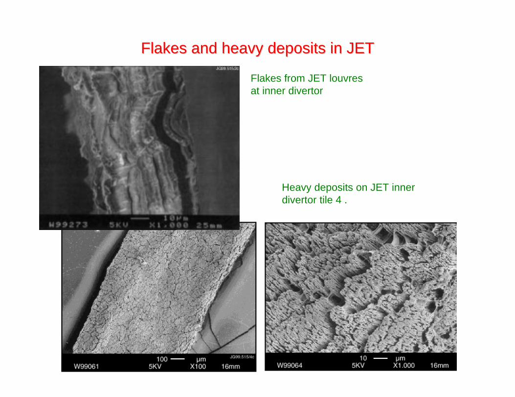
Flakes and heavy deposits in JETFlakes and heavy deposits in JET
Flakes from JET louvresat inner divertor
Heavy deposits on JET innerdivertor tile 4 .
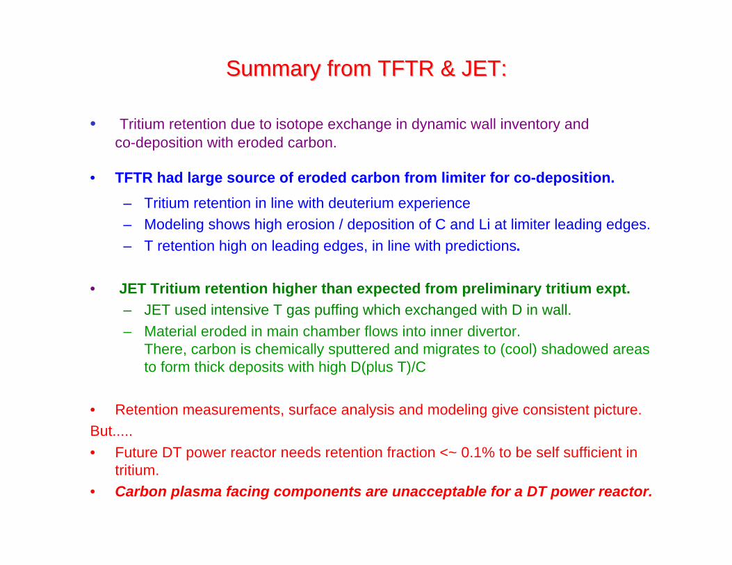
Summary from TFTR & JET:Summary from TFTR & JET:
• Tritium retention due to isotope exchange in dynamic wall inventory andco-deposition with eroded carbon.
• TFTR had large source of eroded carbon from limiter for co-deposition.
– Tritium retention in line with deuterium experience– Modeling shows high erosion / deposition of C and Li at limiter leading edges.
– T retention high on leading edges, in line with predictions.
• JET Tritium retention higher than expected from preliminary tritium expt.– JET used intensive T gas puffing which exchanged with D in wall.
– Material eroded in main chamber flows into inner divertor.There, carbon is chemically sputtered and migrates to (cool) shadowed areasto form thick deposits with high D(plus T)/C
• Retention measurements, surface analysis and modeling give consistent picture.But.....
• Future DT power reactor needs retention fraction <~ 0.1% to be self sufficient intritium.
• Carbon plasma facing components are unacceptable for a DT power reactor.
Retention in metal walledRetention in metal walled tokamaks tokamaks
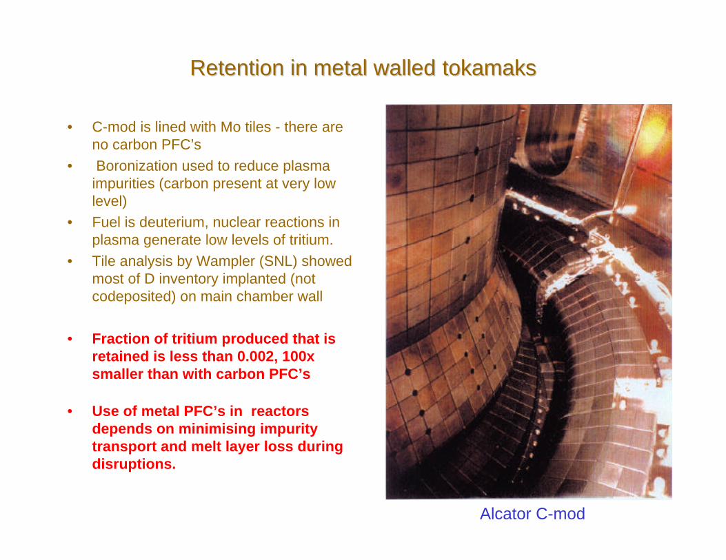
• C-mod is lined with Mo tiles - there areno carbon PFC’s
• Boronization used to reduce plasmaimpurities (carbon present at very lowlevel)
• Fuel is deuterium, nuclear reactions inplasma generate low levels of tritium.
• Tile analysis by Wampler (SNL) showedmost of D inventory implanted (notcodeposited) on main chamber wall
• Fraction of tritium produced that isretained is less than 0.002, 100xsmaller than with carbon PFC’s
• Use of metal PFC’s in reactorsdepends on minimising impuritytransport and melt layer loss duringdisruptions.
Alcator C-mod
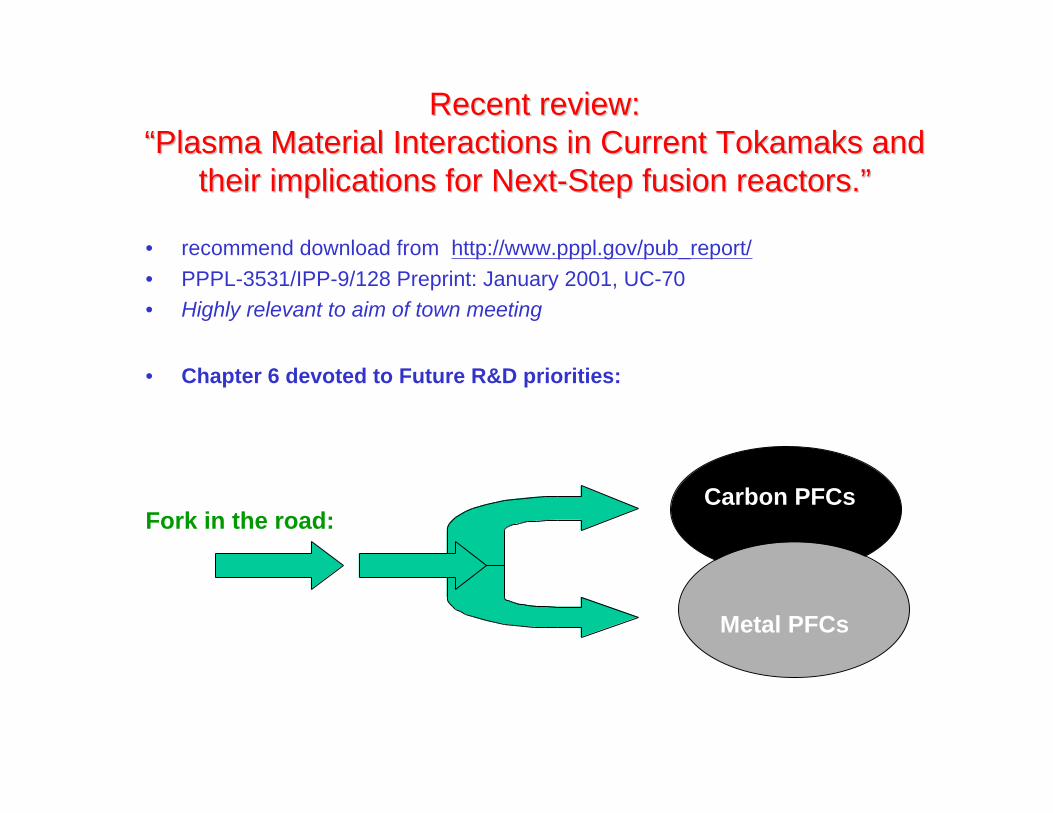
Recent review:Recent review:“Plasma Material Interactions in Current Tokamaks and“Plasma Material Interactions in Current Tokamaks and
their implications for Next-Step fusion reactors.”their implications for Next-Step fusion reactors.”
• recommend download from http://www.pppl.gov/pub_report/
• PPPL-3531/IPP-9/128 Preprint: January 2001, UC-70• Highly relevant to aim of town meeting
• Chapter 6 devoted to Future R&D priorities:
Fork in the road:Carbon PFCs
Metal PFCs

R&D issues for carbon PFCsR&D issues for carbon PFCs
Some key points:
• Frequent replacements of PFCs needed due to ~10nm/s erosion
• Flux dependence of chemical erosion yield and sticking coefficients of
radicals still an open question.
• SOL flows need to be better diagnosed and understood
• Behavior of mixed materials uncertain
• Disruption and ELM loads a major challenge issues include vapor
shielding, brittle destruction....
• Tritium retention unsustainable in power reactors
R&D issues for metal PFC’sR&D issues for metal PFC’s
• Encouraging results from C-mod (Mo wall), and ASDEX (W-coated
divertor plates and central column).
• W ‘brush’ materials tested up to 20 MW/m2.
but....
• Control of transport and MHD in alpha heated plasmas critical (core
high–Z impurity levels detrimental to plasma performance even at ~10-5).
• Disruption and ELM loads a major challenge
– issues include melt layer loss, vapor shielding
– Disruptions need to be very rare
– High confinement without ELMs needed.
• Data on neutron effects on tungsten sparse due to activation.
• Public acceptance of handling/ disposal of activated tungsten

Common R&D issuesCommon R&D issues
• Minimization, control and accountancy of tritium inventory a criticalissue.
• Tritium needed in burning plasma is small fraction of total.– Fast regeneration of in-vessel cryopumps would help reduce
inventory.– Efficient fueling reduced needed total tritium inventory and aids
tritium self sufficiency.• Ar and Ne injection planned to control divertor detachment but..
– will become activated, making current tritium detectors unusable forexhaust stream - new detection technology needed.
• Advanced plasma scenarios with high edge temperatures will result insevere erosion.
• Wall conditioning e.g. boronization, over 1000 s pulses, an issue• Behavior of mixed materials uncertain• In-vessel dust diagnosis to demonstrate compliance with regulatory
limits a major challenge• Tritium removal/decontamination in areas that require hands-on
maintenance also challenging.
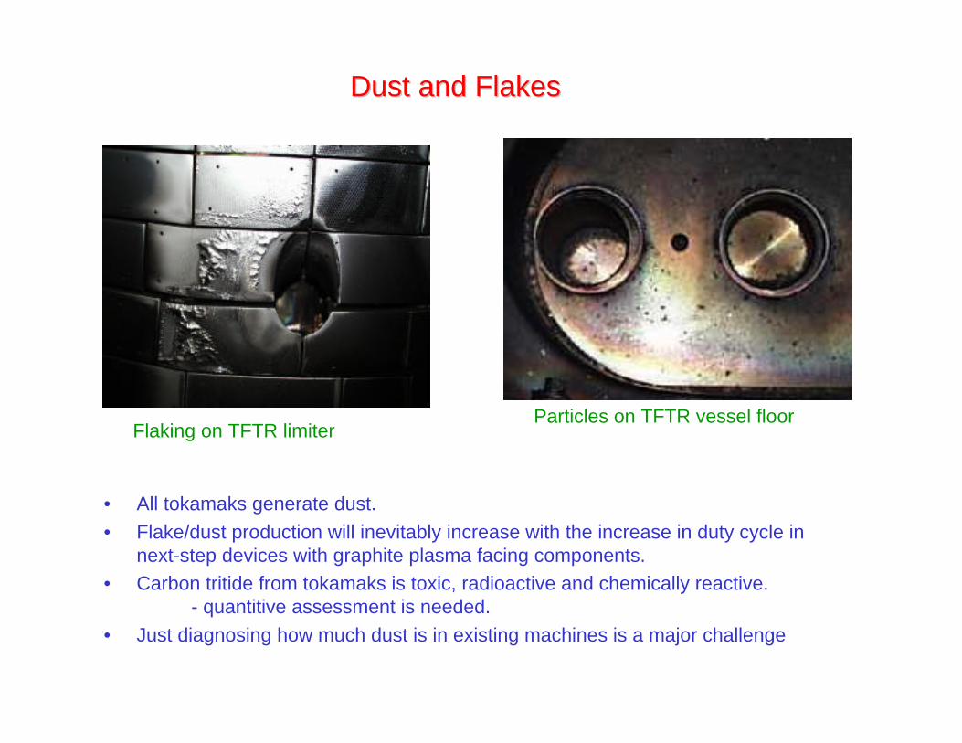
Flaking on TFTR limiter
Dust and FlakesDust and Flakes
• All tokamaks generate dust.
• Flake/dust production will inevitably increase with the increase in duty cycle innext-step devices with graphite plasma facing components.
• Carbon tritide from tokamaks is toxic, radioactive and chemically reactive.- quantitive assessment is needed.
• Just diagnosing how much dust is in existing machines is a major challenge
Particles on TFTR vessel floor

TFTR dust analysisTFTR dust analysis(collaboration with Y.S. Cheng,(collaboration with Y.S. Cheng, Lovlace Lovlace Respiratory Research Institute) Respiratory Research Institute)
• Dust is respirable and can staysuspended in air for a long time
• Count Mean Diameter (CMD)=1.25 µm
• Geometric Standard Deviation (GSD)=1.74 µm
• Currently NO standards for occupationalexposure to tritiated graphite dust.
• In vitro dissolution rate in simulated lungfluid: > 90% of tritium remained inparticles after 110 d (HTO eliminated from body in 10 d)
• ICRP modeling suggests occupationallimit (DAC) is 4.4x lower than HTO- new techniques for real-time monitoringtechnology needed.
• In vivo biological studies recommended
Microscopic image of TFTR dust
Carbon Tritide Particles
Project Area Diameter, µm1 10
∆N
/NT
∆log d
0.2
0.4
0.6
0.8
0.0
1.0
Particle size distribution
Project area diameter µm,
1.0
0.01.0 10.0
∆ N
/NT
/∆
log
d
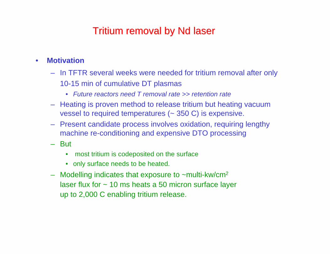
Tritium removal byTritium removal by Nd Nd laser laser
• Motivation
– In TFTR several weeks were needed for tritium removal after only10-15 min of cumulative DT plasmas
• Future reactors need T removal rate >> retention rate
– Heating is proven method to release tritium but heating vacuumvessel to required temperatures (~ 350 C) is expensive.
– Present candidate process involves oxidation, requiring lengthymachine re-conditioning and expensive DTO processing
– But• most tritium is codeposited on the surface
• only surface needs to be heated.
– Modelling indicates that exposure to ~multi-kw/cm2
laser flux for ~ 10 ms heats a 50 micron surface layerup to 2,000 C enabling tritium release.
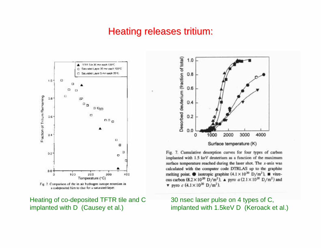
Heating releases tritium:Heating releases tritium:
Heating of co-deposited TFTR tile and Cimplanted with D (Causey et al.)
30 nsec laser pulse on 4 types of C,implanted with 1.5keV D (Keroack et al.)
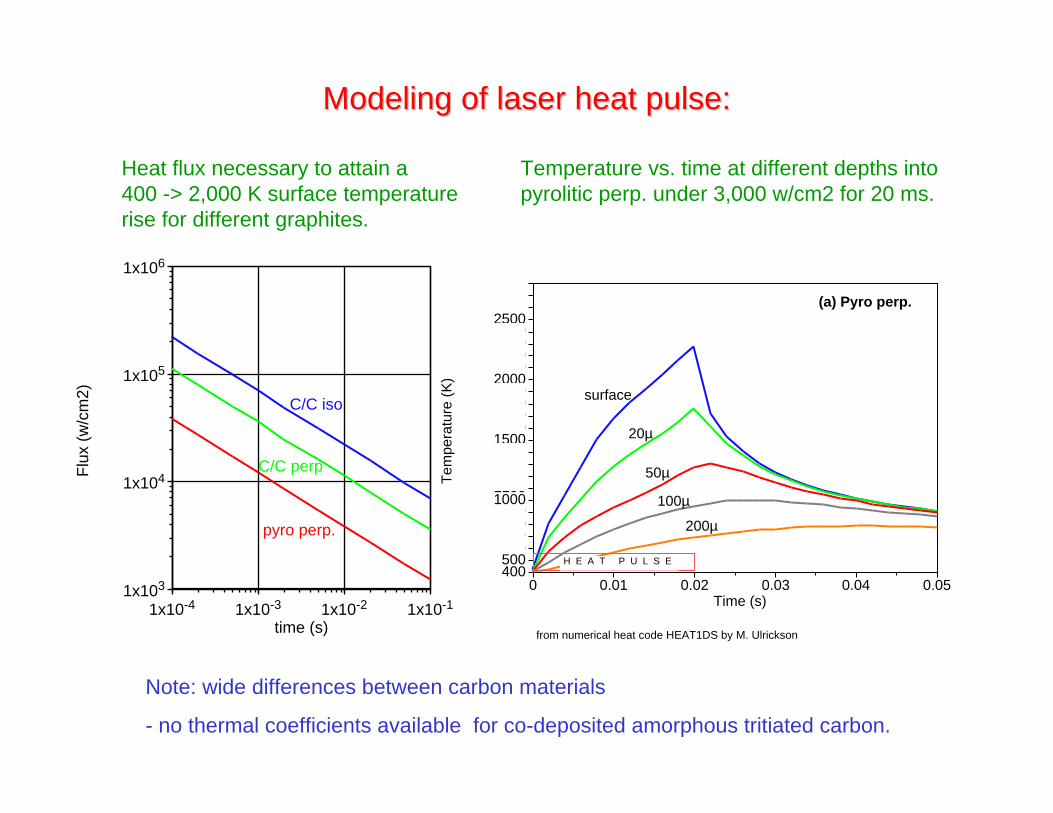
Modeling of laser heat pulse:Modeling of laser heat pulse:
1x10³
1x10⁴
1x10⁵
1x10⁶
1x10⁻⁴ 1x10⁻³ 1x10⁻² 1x10⁻¹
Flu
x (w
/cm
2)
time (s)
pyro perp.
C/C perp
C/C iso
Heat flux necessary to attain a400 -> 2,000 K surface temperaturerise for different graphites.
400500600700800900
1000110012001300140015001600170018001900200021002200230024002500260027002800
0 0.01 0.02 0.03 0.04 0.05
Tem
pera
ture
(K
)
Time (s)
(a) Pyro perp.
surface
20µ
50µ
100µ
200µ
from numerical heat code HEAT1DS by M. Ulrickson
H E A T P U L S E
Temperature vs. time at different depths intopyrolitic perp. under 3,000 w/cm2 for 20 ms.
Note: wide differences between carbon materials
- no thermal coefficients available for co-deposited amorphous tritiated carbon.
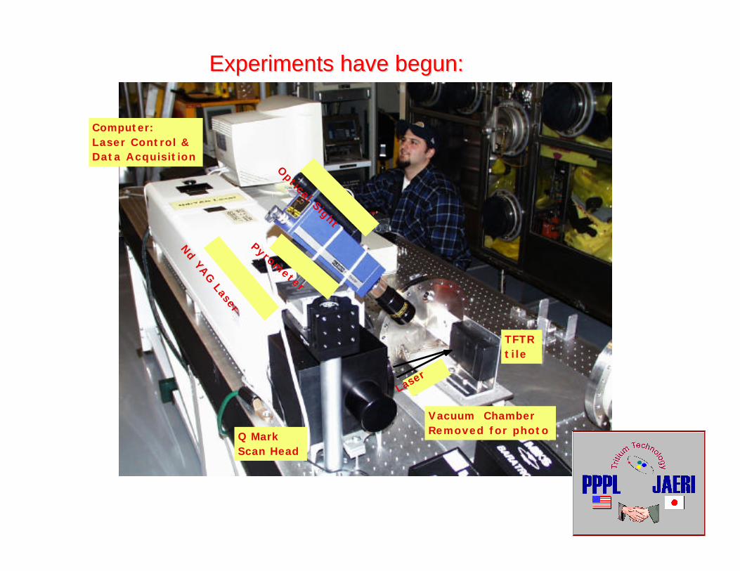
Experiments have begun:Experiments have begun:
Nd YA
G Laser
Pyrometer
Optical Sight
Computer: Laser Control & Data Acquisition
Q Mark Scan Head
TFTRtile
Vacuum ChamberRemoved for photo
Lase
r

1st results: TFTR DT tile before and after1st results: TFTR DT tile before and after Nd Nd laser exposure laser exposure
Cube cut from CFCtile KC17 2E beforelaser exposuresize: 7/8” a side
In chamber after exposure to Nd laser2000 mm/s @ 40 W and200 mm/s @ 6 W
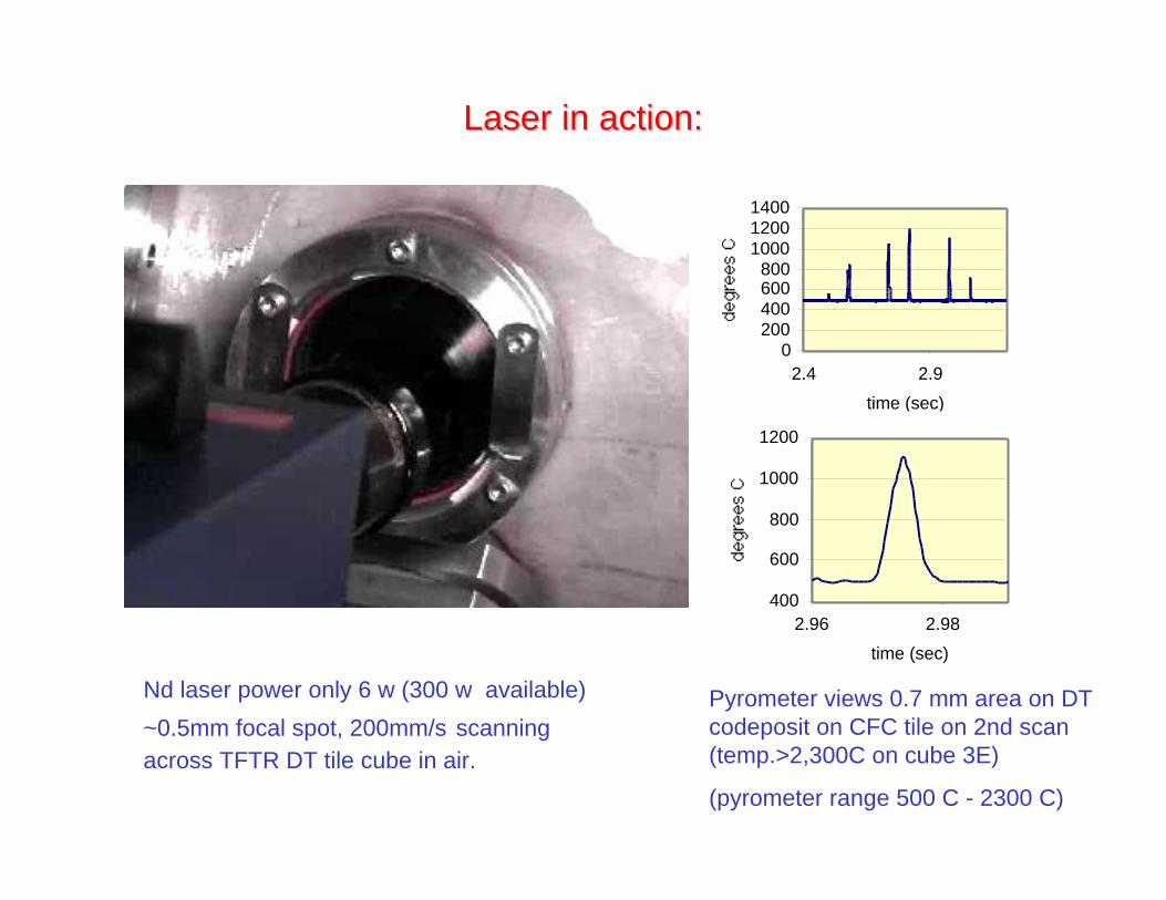
Laser in action:Laser in action:
Pyrometer views 0.7 mm area on DTcodeposit on CFC tile on 2nd scan(temp.>2,300C on cube 3E)
(pyrometer range 500 C - 2300 C)
Nd laser power only 6 w (300 w available)
~0.5mm focal spot, 200mm/s scanningacross TFTR DT tile cube in air.
0200400600800
100012001400
2.4 2.9
time (sec)
400
600
800
1000
1200
2.96 2.98
time (sec)

Preliminary data on tritium released in first expt.Preliminary data on tritium released in first expt.
• Surface tritium (measured with open wall ion chamber)decreased
– from 51 µCi/cm2 before
– to 14 µCi/cm2 after Nd laser exposure
• 2.6 mCi released by Nd laser
• 10.7 mCi released on exposure on baking at 500 C for 1hour in air.
• Non plasma facing surface on cube 3E heated to> 2300 C by Nd laser showed complete removal ofsurface tritium.
– Powerful decontamination technique.
• Need to optimize scan rate, laser power, laser focal spotsize, investigate desorption processes, surface effects....

The Future ? - Voyager IIThe Future ? - Voyager II
• 3e7 J required to heat top 100microns of 50 m2 divertor.- corresponds to output of1kW laser for only 8 hours !
• Nd laser can be coupled viafiberoptic
• Potential for oxygen freetritium release in operatingtokamak
– avoid deconditioning plasmafacing surfaces
– avoid HTO generation(HTO is 10,000x morehazardous than T2 and veryexpensive to reprocess)
Further reading:Further reading:
• “Studies of tritiated co-deposited layers in TFTR”
J. Nucl. Mater. 266(1999) 941. PSI-14 J. Nucl. Mater in press
• “Tritium Retention and Cleanup in JET” Fus. Eng. & Des. 47 (1999) 233
• “Long Term Retention of Deuterium and Tritium in Alcator C-mod”Proceedings of 18th Symposium on Fusion Energy, (1999) p.267.
• “Tritium experience in large tokamaks: Application to ITER”Nuclear Fusion 39, 271, (1999)
• “Plasma-material Interactions in Current Tokamaks and their Implications for Next-
step Fusion Reactors.”
PPPL-3531/IPP-9/128 Preprint: January 2001, UC-70
download from http://www.pppl.gov/pub_report/
Top Related