


Languages
Pages
Legal


Doc Ref: Gen325.6 Control: 49F61154‐5A8A‐4509‐B773‐E7FDCBD498DA
Tetra Nova Industrial Systems, LLC.
Innovation is in our DNA
Tetra-Nova
Digital Measurement Solution
Quick Start - User Guide
Genesis Series Measurement System

Tetra Nova Industrial Systems, LLC. www.Tetra-Nova.com
Doc Ref: Gen325.6 Control: 49F61154‐5A8A‐4509‐B773‐E7FDCBD498DA page 2 of 16
Contents Introduction .................................................................................................................................................. 3
System Overview .......................................................................................................................................... 3
Specifications ................................................................................................................................................ 4
How to read our scale part number .......................................................................................................... 5
How to read our Bluetooth Module part number .................................................................................... 7
Quick Setup ................................................................................................................................................... 8
Overview ................................................................................................................................................... 8
Linear Scale Mounting .................................................................................................................................. 9
Scale Alignment....................................................................................................................................... 10
Bluetooth Module and Cable Installation ................................................................................................... 12
Tablet Initial Setup ...................................................................................................................................... 13
Downloading the TouchDRO App ............................................................................................................... 13
Overview ................................................................................................................................................. 13
Downloading the App ............................................................................................................................. 13
Setup Your Bluetooth Connection .......................................................................................................... 14
Running the TouchDRO app .................................................................................................................... 14
Warranty ..................................................................................................................................................... 16
Tetra Nova Industrial Systems, LLC. www.Tetra-Nova.com
Doc Ref: Gen325.6 Control: 49F61154‐5A8A‐4509‐B773‐E7FDCBD498DA page 3 of 16
Introduction We’ve worked very hard toward developing great features and functionality into our linear measurement systems and hope you enjoy years of productive use. Toward that goal, we recommend following the guidelines set forth in this document when installing and using your Tetra-Nova measurement system. We note that our measurement systems can be installed on hundreds of different machines and linear systems. Thus, this Quick Start - User Guide document describes the general principals of a typical system setup, providing you the steps you’ll need to follow in order to achieve a perfect installation.
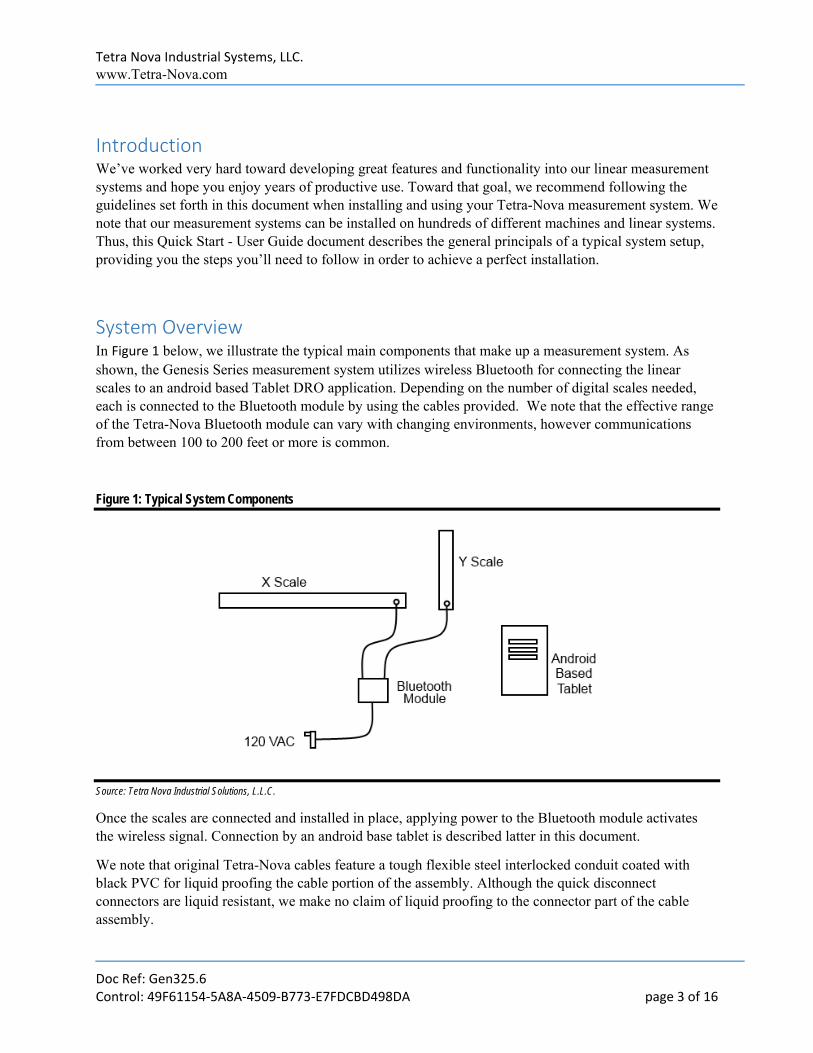
System Overview In Figure 1 below, we illustrate the typical main components that make up a measurement system. As shown, the Genesis Series measurement system utilizes wireless Bluetooth for connecting the linear scales to an android based Tablet DRO application. Depending on the number of digital scales needed, each is connected to the Bluetooth module by using the cables provided. We note that the effective range of the Tetra-Nova Bluetooth module can vary with changing environments, however communications from between 100 to 200 feet or more is common.
Figure 1: Typical System Components
Source: Tetra Nova Industrial Solutions, L.L.C.
Once the scales are connected and installed in place, applying power to the Bluetooth module activates the wireless signal. Connection by an android base tablet is described latter in this document.
We note that original Tetra-Nova cables feature a tough flexible steel interlocked conduit coated with black PVC for liquid proofing the cable portion of the assembly. Although the quick disconnect connectors are liquid resistant, we make no claim of liquid proofing to the connector part of the cable assembly.
Tetra Nova Industrial Systems, LLC. www.Tetra-Nova.com
Doc Ref: Gen325.6 Control: 49F61154‐5A8A‐4509‐B773‐E7FDCBD498DA page 4 of 16
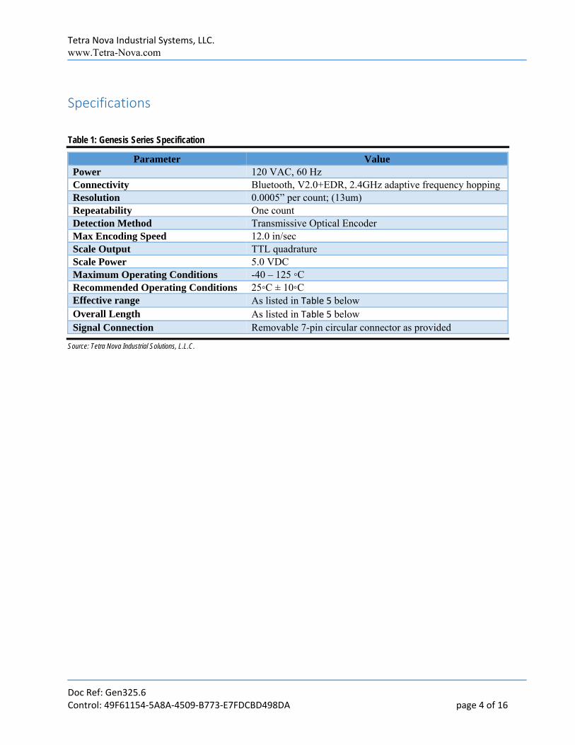
Specifications
Table 1: Genesis Series Specification
Parameter Value Power 120 VAC, 60 Hz Connectivity Bluetooth, V2.0+EDR, 2.4GHz adaptive frequency hopping Resolution 0.0005” per count; (13um) Repeatability One count Detection Method Transmissive Optical Encoder Max Encoding Speed 12.0 in/sec Scale Output TTL quadrature Scale Power 5.0 VDC Maximum Operating Conditions -40 – 125 ◦C Recommended Operating Conditions 25◦C ± 10◦C Effective range As listed in Table 5 below Overall Length As listed in Table 5 below Signal Connection Removable 7-pin circular connector as provided
Source: Tetra Nova Industrial Solutions, L.L.C.
Tetra Nova Industrial Systems, LLC. www.Tetra-Nova.com
Doc Ref: Gen325.6 Control: 49F61154‐5A8A‐4509‐B773‐E7FDCBD498DA page 5 of 16
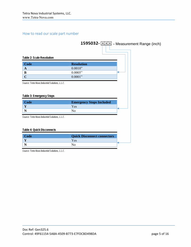
How to read our scale part number
- Measurement Range (inch)
Table 2: Scale Resolution
Code Resolution A 0.0010” B 0.0005” C 0.0001”
Source: Tetra Nova Industrial Solutions, L.L.C.
Table 3: Emergency Stops
Code Emergency Stops Included Y Yes N No
Source: Tetra Nova Industrial Solutions, L.L.C.
Table 4: Quick Disconnects
Code Quick Disconnect connectors Y Yes N No
Source: Tetra Nova Industrial Solutions, L.L.C.
Tetra Nova Industrial Systems, LLC. www.Tetra-Nova.com
Doc Ref: Gen325.6 Control: 49F61154‐5A8A‐4509‐B773‐E7FDCBD498DA page 6 of 16
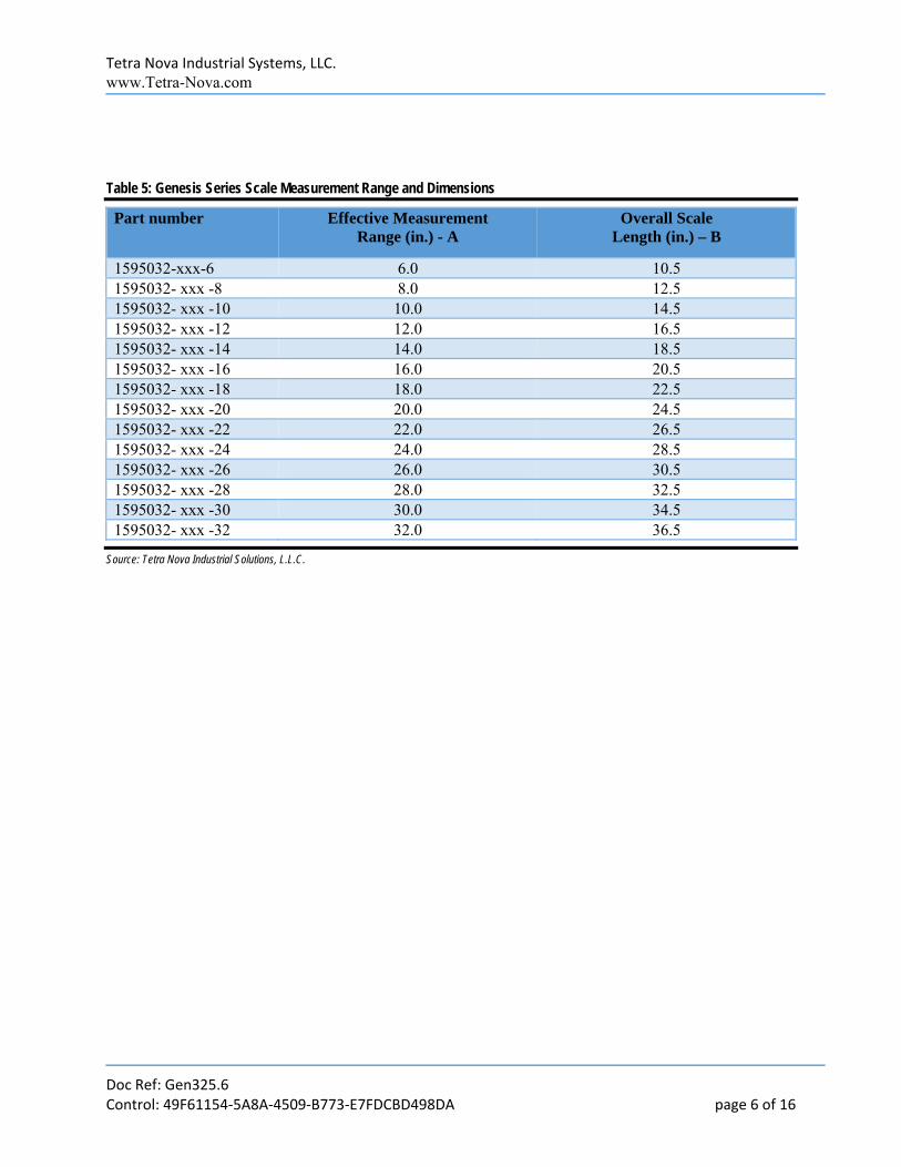
Table 5: Genesis Series Scale Measurement Range and Dimensions
Part number Effective Measurement Range (in.) - A
Overall Scale Length (in.) – B
1595032-xxx-6 6.0 10.5 1595032- xxx -8 8.0 12.5 1595032- xxx -10 10.0 14.5 1595032- xxx -12 12.0 16.5 1595032- xxx -14 14.0 18.5 1595032- xxx -16 16.0 20.5 1595032- xxx -18 18.0 22.5 1595032- xxx -20 20.0 24.5 1595032- xxx -22 22.0 26.5 1595032- xxx -24 24.0 28.5 1595032- xxx -26 26.0 30.5 1595032- xxx -28 28.0 32.5 1595032- xxx -30 30.0 34.5 1595032- xxx -32 32.0 36.5
Source: Tetra Nova Industrial Solutions, L.L.C.
Tetra Nova Industrial Systems, LLC. www.Tetra-Nova.com
Doc Ref: Gen325.6 Control: 49F61154‐5A8A‐4509‐B773‐E7FDCBD498DA page 7 of 16
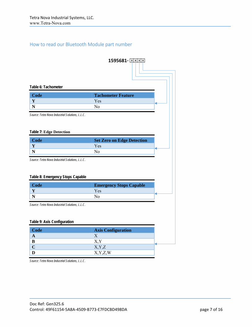
How to read our Bluetooth Module part number
Table 6: Tachometer
Code Tachometer Feature Y Yes N No
Source: Tetra Nova Industrial Solutions, L.L.C.
Table 7: Edge Detection
Code Set Zero on Edge Detection Y Yes N No
Source: Tetra Nova Industrial Solutions, L.L.C.
Table 8: Emergency Stops Capable
Code Emergency Stops Capable Y Yes N No
Source: Tetra Nova Industrial Solutions, L.L.C.
Table 9: Axis Configuration
Code Axis Configuration A X B X,Y C X,Y,Z D X,Y,Z,W
Source: Tetra Nova Industrial Solutions, L.L.C.
Tetra Nova Industrial Systems, LLC. www.Tetra-Nova.com
Doc Ref: Gen325.6 Control: 49F61154‐5A8A‐4509‐B773‐E7FDCBD498DA page 8 of 16
Quick Setup Tetra‐Nova Genesis Series linear scales all have similar setup requirements and this section highlights
the basic principles of installation. Please read and understand the directions prior to attempting an
installation to help prevent permanent damage to your scales that falls outside of our standard
warrantee.
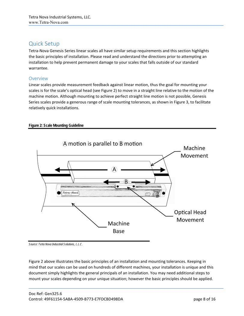
Overview Linear scales provide measurement feedback against linear motion, thus the goal for mounting your
scales is for the scale’s optical head (see Figure 2) to move in a straight line relative to the motion of the
machine motion. Although mounting to achieve perfect straight line motion is not possible, Genesis
Series scales provide a generous range of scale mounting tolerances, as shown in Figure 3, to facilitate
relatively quick installations.
Figure 2: Scale Mounting Guideline
Source: Tetra Nova Industrial Solutions, L.L.C.
Figure 2 above illustrates the basic principles of an installation and mounting tolerances. Keeping in
mind that our scales can be used on hundreds of different machines, your installation is unique and this
document simply highlights the general principals of an installation. You may need additional steps to
mount your scales depending on your unique situation; however the basic principles should be applied.

Tetra Nova Industrial Systems, LLC. www.Tetra-Nova.com
Doc Ref: Gen325.6 Control: 49F61154‐5A8A‐4509‐B773‐E7FDCBD498DA page 9 of 16
Typical installations employ 90◦ angle brackets or standoffs to permanently mount the scale to the
machine base or to secure the optical head to the machine movement.
Figure 2 also shows the scale mounted with the optical head on top. Although the Genesis scales have a
black seal to protect against dust contamination to the optical sensor, in high dust, dirt, or metal flake
environments, it is recommended to install the scale with the optical head facing down. A protective
shield can also be installed just above the scale to prevent falling debris from entering the scales
interior.
Linear Scale Mounting As shown in Figure 2, your scale mounting should be configured so that the scale is as close as possible
to horizontal with the machine movement over the entire length of the scale. Once the scale is mounted,
connecting the optical head to the machine movement is the next step. Do not mount the optical head
beyond a 0.1” vertical or horizontal gaps as shown in Figure 3 or damage may occur to your scale.
Figure 3: Optical Head Diagram with movement freedom
Source: Tetra Nova Industrial Solutions, L.L.C.
In addition, using your hand, move the optical head from end to end on the scale and note the stopping
points near the ends (about 0.6” from the red end caps). At no point should your machine movement
Tetra Nova Industrial Systems, LLC. www.Tetra-Nova.com
Doc Ref: Gen325.6 Control: 49F61154‐5A8A‐4509‐B773‐E7FDCBD498DA page 10 of 16
cause the end of optical head to extend to or past the stopping points on each end of the scale or
permanent damage may occur. You may consider marking the stopping points for reference or mount
the scales so that machine movement does not extend to the stops. Spreading the black seal to expose
the leading edge of the red end cap will also provide an indication of the stopping point for the front
edge of the optical head.
For the Genesis Series, there is approximately 0.1” of freedom in vertical movement and 0.1” of
freedom in horizontal movement for the optical head. The goal is to mount the optical head and then
align the optical head to the machine movement so that the head is as close to the center of this
movement freedom as possible (See Figure 3).
In other words, the optical head has about 0.1” of freedom to move horizontally across the scale. When
mounted, the optical head should be fixed to a position that is about the center of that movement, or
about 0.05” across. Similarly, the optical head has about 0.1” of freedom to move vertically up and
down from the scale. When mounted, the optical head should be fixed to a position that is about the
center of that movement, or about 0.05” up.
See the next steps describe a technique for optical head alignment.
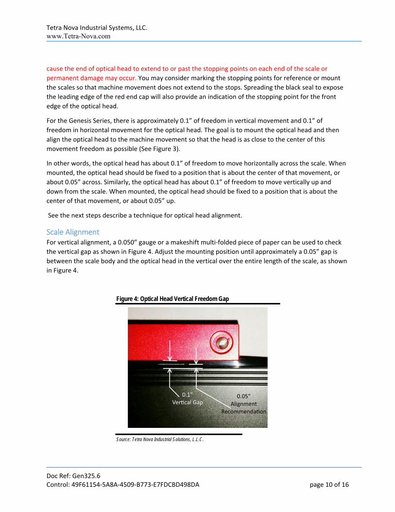
Scale Alignment For vertical alignment, a 0.050” gauge or a makeshift multi‐folded piece of paper can be used to check
the vertical gap as shown in Figure 4. Adjust the mounting position until approximately a 0.05” gap is
between the scale body and the optical head in the vertical over the entire length of the scale, as shown
in Figure 4.
Figure 4: Optical Head Vertical Freedom Gap
Source: Tetra Nova Industrial Solutions, L.L.C.
Tetra Nova Industrial Systems, LLC. www.Tetra-Nova.com
Doc Ref: Gen325.6 Control: 49F61154‐5A8A‐4509‐B773‐E7FDCBD498DA page 11 of 16
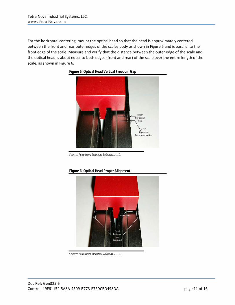
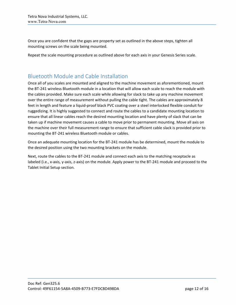
For the horizontal centering, mount the optical head so that the head is approximately centered
between the front and rear outer edges of the scales body as shown in Figure 5 and is parallel to the
front edge of the scale. Measure and verify that the distance between the outer edge of the scale and
the optical head is about equal to both edges (front and rear) of the scale over the entire length of the
scale, as shown in Figure 6.
Figure 5: Optical Head Vertical Freedom Gap
Source: Tetra Nova Industrial Solutions, L.L.C.
Figure 6: Optical Head Proper Alignment
Source: Tetra Nova Industrial Solutions, L.L.C.
Tetra Nova Industrial Systems, LLC. www.Tetra-Nova.com
Doc Ref: Gen325.6 Control: 49F61154‐5A8A‐4509‐B773‐E7FDCBD498DA page 12 of 16
Once you are confident that the gaps are property set as outlined in the above steps, tighten all
mounting screws on the scale being mounted.
Repeat the scale mounting procedure as outlined above for each axis in your Genesis Series scale.
Bluetooth Module and Cable Installation Once all of you scales are mounted and aligned to the machine movement as aforementioned, mount
the BT‐241 wireless Bluetooth module in a location that will allow each scale to reach the module with
the cables provided. Make sure each scale while allowing for slack to take up any machine movement
over the entire range of measurement without pulling the cable tight. The cables are approximately 8
feet in length and feature a liquid‐proof black PVC coating over a steel interlocked flexible conduit for
ruggedizing. It is highly suggested to connect and route the cables to a candidate mounting location to
ensure that all linear cables reach the desired mounting location and have plenty of slack that can be
taken up if machine movement causes a cable to move prior to permanent mounting. Move all axis on
the machine over their full measurement range to ensure that sufficient cable slack is provided prior to
mounting the BT‐241 wireless Bluetooth module or cables.
Once an adequate mounting location for the BT‐241 module has be determined, mount the module to
the desired position using the two mounting brackets on the module.
Next, route the cables to the BT‐241 module and connect each axis to the matching receptacle as
labeled (i.e., x‐axis, y‐axis, z‐axis) on the module. Apply power to the BT‐241 module and proceed to the
Tablet Initial Setup section.
Tetra Nova Industrial Systems, LLC. www.Tetra-Nova.com
Doc Ref: Gen325.6 Control: 49F61154‐5A8A‐4509‐B773‐E7FDCBD498DA page 13 of 16
Tablet Initial Setup Your Genesis series DRO package may or may not have included an Android based tablet, however
practically speaking, just about any Android based tablet with Bluetooth should work, including many
cell phones. That said, if your package included a new Tablet, open the package and go through the
normal Tablet setup as initiated when you power the device up for the first time. It is suggested that you
enter your google account information or create a google account prior to setting up the tablet as this
information is required to access the Touch DRO application from Google Play.
Downloading the TouchDRO App
Overview Tetra‐Nova Genesis Series Scales are compatible with the popular open source DRO application
“TouchDRO” created and managed by Yuriy Krushelnytskiy. With permission from Yuri, Tetra‐Nova has
developed the BT‐241 module to interface Tetra‐Nova scales directly with the TouchDRO application.
We find the open source application very attractive as community updates, improvements, and a
suggestion have the ability to constantly improve the application far beyond most commercial versions
and allows users to directly influence future features. Relative to a traditional dedicated hardware
keypad/display, we believe the tablet platform coupled with fast open source innovation cycles is far
more capable and feature rich that even the most comprehensive legacy system. Thus, Tetra‐Nova
believe that our Genesis Series tablet based open source DRO configurations represent the next
generation of digital measurement systems. We think you’ll agree.
Downloading the App Using the Android device to be paired with the Genesis Series DRO system, tap the applications icon to
display the installed applications on your Android device. Navigate to the Google Play icon and tap to
run Google Play.
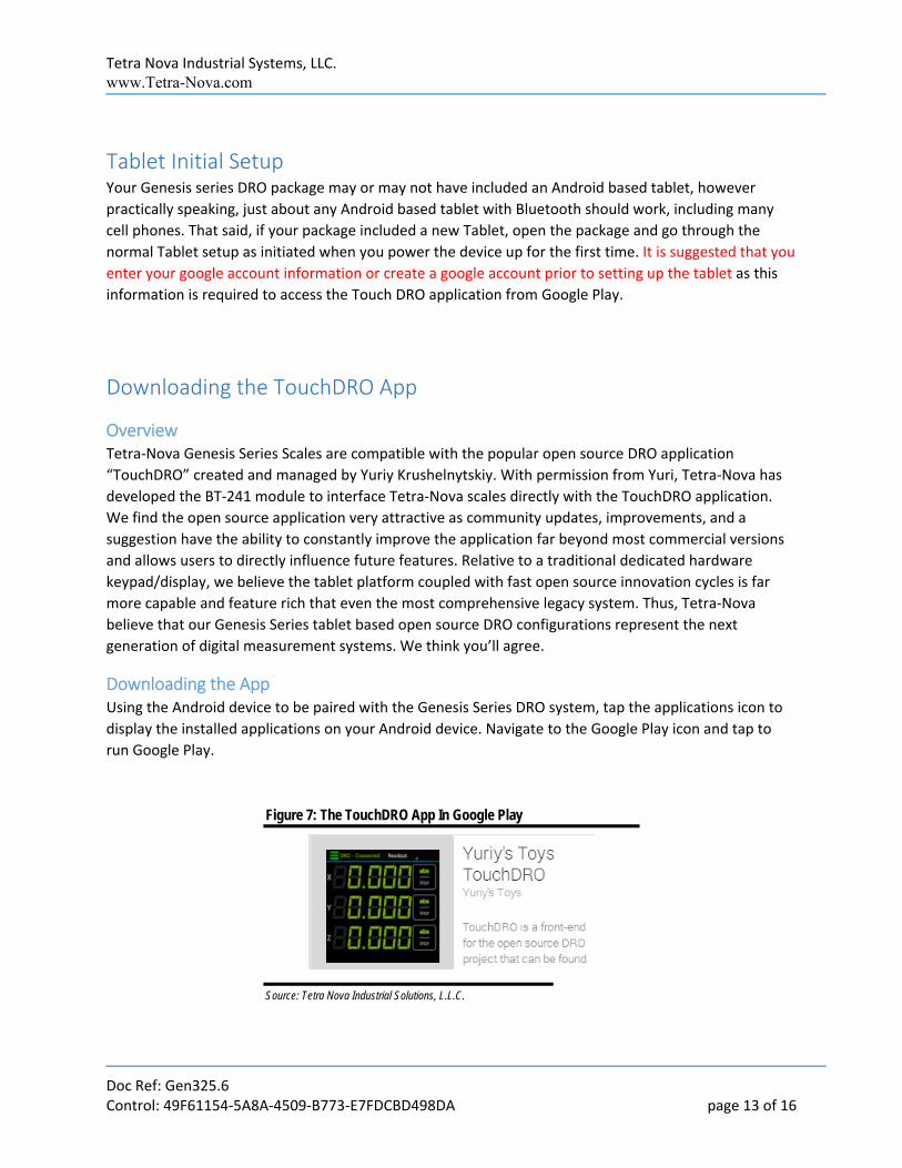
Figure 7: The TouchDRO App In Google Play
Source: Tetra Nova Industrial Solutions, L.L.C.

Tetra Nova Industrial Systems, LLC. www.Tetra-Nova.com
Doc Ref: Gen325.6 Control: 49F61154‐5A8A‐4509‐B773‐E7FDCBD498DA page 14 of 16
Using the search bar on the Google Play application, enter “TouchDRO” and initiate a search (e.g., tap
the magnifying glass, hit enter, hit return, etc.). Google play should return search results with the
application shown it Figure 7 displayed. You’ll need to configure the Bluetooth connection prior to
running the app, but for now tap on the TouchDRO icon and then install the application.
Setup Your Bluetooth Connection
First, plug in your BT‐241 Wireless Bluetooth Module to activate its signal.
Once the application has been downloaded, you’ll need to set up the Tablet Bluetooth connection to the
Genesis BT‐241 module prior to connecting the Touch DRO application to your scales.
Figure 8: Typical Tablet Settings Icon
Settings
Settings
Source: Tetra Nova Industrial Solutions, L.L.C.
Find the Settings icon on you tablet (e.g., see Figure 8) and under the wireless & Networks category,
locate the Bluetooth line and make sure that Bluetooth is set to “ON” (if available). Next tap the
Bluetooth line to expose the tablets Bluetooth settings panel.
Next verify that your BT‐241 is plugged into power prior to scanning. Locate “Scan” or “Search for
Devices” to sweep your location for active Bluetooth devices. Once your location has been swept for
Bluetooth devices, one of the “Available Devices” listed should be “HC‐06” which indicated that
scanning has found your BT‐241 device. Tap on the “HC‐06” line to connect to the BT‐241 module. You
should then be prompted to enter the devices’ Pin key. Tap the input line and enter 1234 to pair the
BT‐241 to your tablet.
Exit the settings application by hitting the home button or back.
You have successfully paired the BT‐241 module to the tablet.
Running the TouchDRO app Find the TouchDRO app icon shown in Figure 7 and tap the icon to launch the program.
Tetra Nova Industrial Systems, LLC. www.Tetra-Nova.com
Doc Ref: Gen325.6 Control: 49F61154‐5A8A‐4509‐B773‐E7FDCBD498DA page 15 of 16
Next using the triple dot in the top right of the tablet window or using the left tablet button (depending
on your tablet) access the TouchDRO program settings window. You can choose many different items to
customize the look and feel of the application; however the one mandatory setting that must be set is
the Axis CPI setting for EACH axis (i.e., X, Y, Z, and W as appropriate).
For each axis, set the “Axis CPI” setting to 2000
Additionally, you may enable Invert Readout to configure which direction of machine movement
represents + or – displacement on your readout.
Although, the application is not a Tetra‐Nova product, we believe that that application is intuitive and
has an active user group that will be happy to assist with any questions regarding use of the application.
Tetra‐Nova does not support the TouchDRO application, we only support interface and scale related
issues.
Your system is now ready for years of service.

Tetra Nova Industrial Systems, LLC. www.Tetra-Nova.com
Doc Ref: Gen325.6 Control: 49F61154‐5A8A‐4509‐B773‐E7FDCBD498DA page 16 of 16
Warranty
WARRANTY
This product has been carefully tested and
inspected before leaving the manufacturer. If
used and cared for properly, this tool will give
the finest results obtainable. We warrant it to
be free of defects in materials and
workmanship for a period of twelve months
from the date of purchase.
Tetra Nova Industrial Systems, LLC.
Tetra‐Nova.com
Top Related