


Languages
Pages
Legal

RECENT DEVELOPMENT OF STRUCTURAL HEALTH MONITORING TECHNOLOGIES FOR AIRCRAFT
COMPOSITE STRUCTURES IN JAPAN
N. Takeda and S. Minakuchi
Dept. Advanced Energy, Graduate School of Frontier Sciences The University of Tokyo
Mail Box 302, 5-1-5 Kashiwanoha, Kashiwa-shi, Chiba 277-8561, Japan [email protected], [email protected]
SUMMARY A review is presented on small-diameter optical fiber sensors for damage monitoring and structural health monitoring (SHM) of composite structures. Then, recent results in the current ACS-SIDE (Structural Integrity Diagnosis and Evaluation of Advanced Composite Structures) project in Japan are presented on optical fiber based SHM for some feasible applications in aerospace applications.
Keywords: Fiber optic sensor, structural health monitoring, composite structures, aerospace structures
INTRODUCTION SHM technologies have been studied extensively in order to assess the safety and the durability of the structures [1]. In addition, for weight saving of airplanes, CFRP laminates are extensively being used for the primary structures. However, the maintenance cost of the structures may increase because of the complicated fracture process of the CFRP laminates. A new technological innovation to reduce the maintenance cost is a health monitoring or management system. At present, optical fiber sensors are most promising among all [2, 3]. This is because optical fibers have enough flexibility, strength and heat-resistance to be embedded easily into composite laminates.
A most potential candidate for the sensing device is an optical fiber Bragg grating (FBG) sensor [4]. FBG sensors are very sensitive to non-uniform strain distribution along the entire length of the grating, which deforms the reflection spectrum from the FBG sensors. Taking advantage of the sensitivity, microscopic damages that cause non-uniform strain distribution in CFRP laminates can be detected.
When the optical fiber sensors are embedded into composite materials, however, there is a possibility of degradation in mechanical properties of host materials. Hence, the authors and Hitachi Cable, Ltd. have recently developed small-diameter optical fiber and its fiber Bragg grating (FBG) sensor that are suitable for embedment inside a lamina of composite laminates without strength reduction [5].
In the following, a brief summary is presented for some previous studies on the small-diameter FBG sensors for damage monitoring and SHM of composite structures.
FBGCoreCladding
d
IIIR
IT
0.53 µm10 mm
Refr
activ
e In
dex
Cladding
0o Ply
90o Ply
Coating
50µm
Conventional Fiber Small-Diameter Fiber
FBGCoreCladding
d
IIIR
IT
0.53 µm10 mm
Refr
activ
e In
dex
FBGCoreCladding
d
IIIR
IT
0.53 µm10 mm
Refr
activ
e In
dex
Cladding
0o Ply
90o Ply
Coating
50µm
Conventional Fiber Small-Diameter Fiber
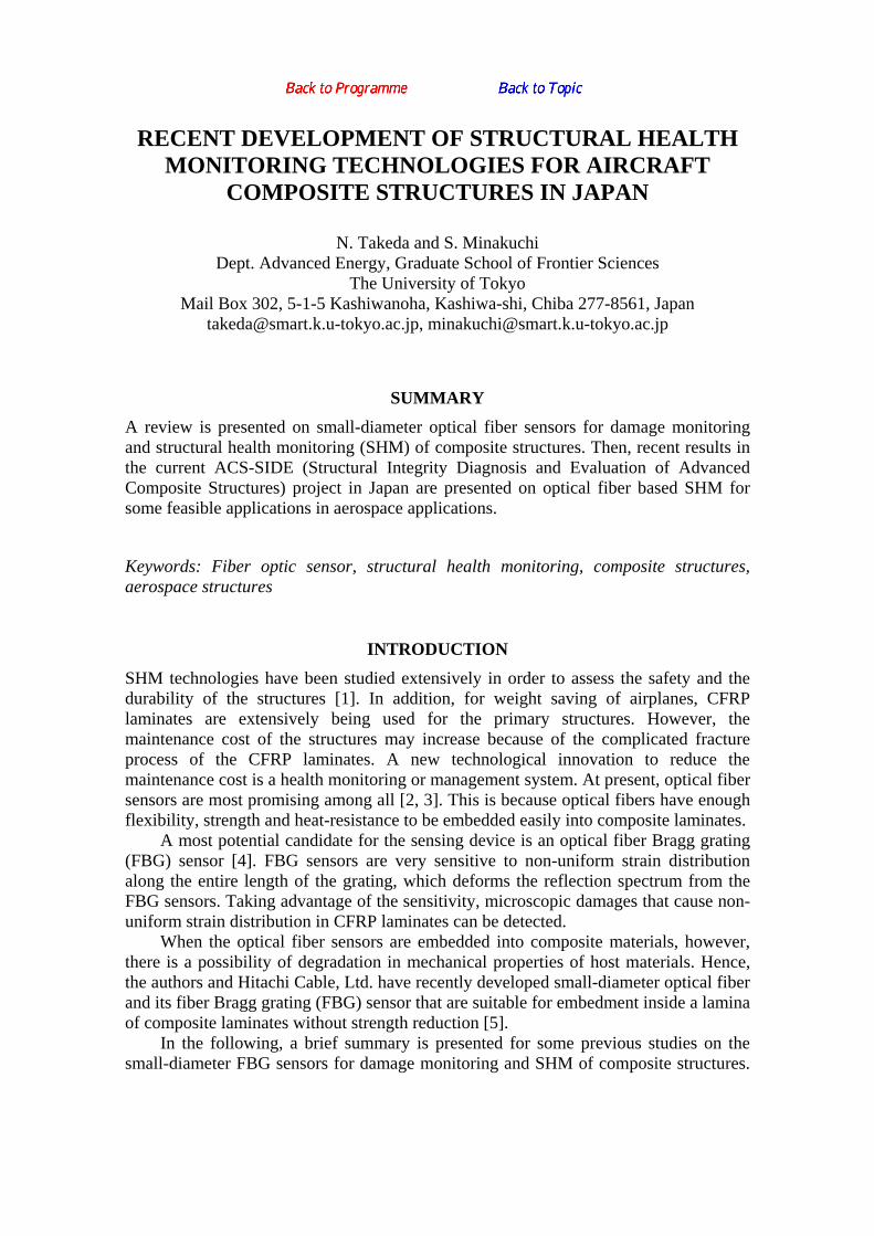
Fig. 2. Conventional and small-diameter
optical fibers embedded in a CFRP lamina and small-diameter FBG sensors with fiber
connection to conventional optical fibers.
Then, some recent results in the current projects are presented on optical fiber based SHM for aerospace composite structures.
DAMAGE DETECTION BY SMALL-DIAMETER FBG SENSORS
Development of Small-Diameter Optical Fibers and FBG Sensors The small diameter optical fibers (both single-mode and multi-mode) were developed and FBG sensors were fabricated with these optical fibers (Fig. 1). The optical fiber is with 40 µm in cladding diameter and 52 µm in polyimide coating diameter, which is easily embedded within one CFRP ply of typically 125 µm in thickness. Such optical fibers have both mechanical and optical properties similar to those of conventional optical fibers with 125 µm in cladding diameter and do not cause any reduction in strength of composites when embedded parallel to reinforcing fibers in laminates [5]. When a small-diameter optical fiber is embedded inside a lamina, resin-rich regions cannot be found around the fiber, as shown in Fig. 2. The polyimide coating relieves the stress concentration around the glass cladding with a proper combination of the stiffness and the thickness. The coating is also highly compatible with epoxy or other high-temperature polymer matrix of CFRP composites under high-temperature exposure during fabrication and also in high-temperature use.
Then, FBG sensors were also successfully developed with these single-mode small-diameter optical fibers, where periodic gratings with approximately 0.53 µm in space were inscribed in the gage section (typically 10 mm in length). When a broadband light is introduced from one end of the fiber, a narrow-band spectrum with a sharp wavelength peak corresponding to the grating spacing is obtained if uniform strain within the gage section can be assumed. FBG sensors are usually used to measure strain and/or temperature through the shift of the wavelength peak [4].
Damage Detection by FBG Sensors FBG sensors are very sensitive to non-uniform strain distribution along the entire length of the grating, which deforms the reflection spectrum from the FBG sensors (Fig. 3).
Polyimide Coating
Cladding
Core
6.5µm40µm52µm
Polyimide Coating
Cladding
Core
6.5µm40µm52µm
Fig. 1. Small-diameter optical fiber
Small-Diameter Optical Fiber
FBG Sensor
GFRP TabA
A
Cross section at A-A 50µm
Cladding
Polyimide Coating
90o Ply
-45o Ply
0o PlySmall-Diameter Optical Fiber
FBG Sensor
GFRP TabA
A
Cross section at A-A 50µm
Cladding
Polyimide Coating
90o Ply
-45o Ply
0o Ply
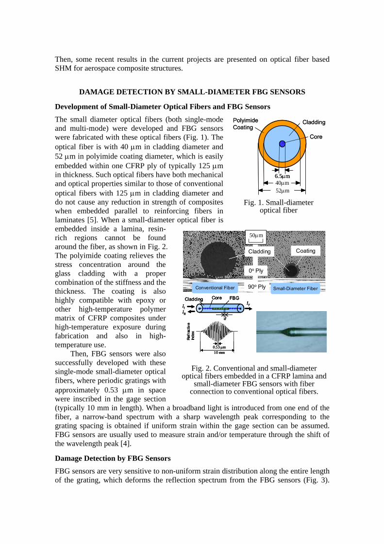
Fig. 4. A small-diameter FBG sensor embedded in the –45o ply for detection of transverse cracks in the adjacent 90o ply of
quasi-isotropic [45/0/-45/90]s laminate.
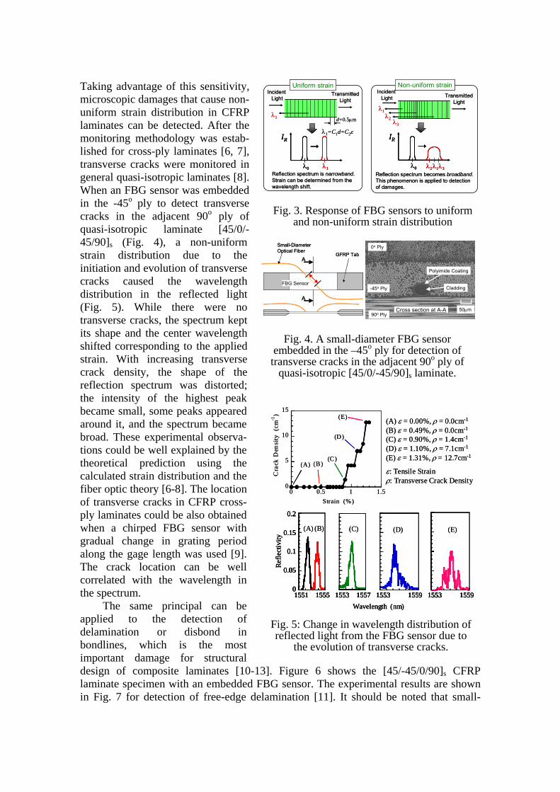
Taking advantage of this sensitivity, microscopic damages that cause non-uniform strain distribution in CFRP laminates can be detected. After the monitoring methodology was estab-lished for cross-ply laminates [6, 7], transverse cracks were monitored in general quasi-isotropic laminates [8]. When an FBG sensor was embedded in the -45o ply to detect transverse cracks in the adjacent 90o ply of quasi-isotropic laminate [45/0/-45/90]s (Fig. 4), a non-uniform strain distribution due to the initiation and evolution of transverse cracks caused the wavelength distribution in the reflected light (Fig. 5). While there were no transverse cracks, the spectrum kept its shape and the center wavelength shifted corresponding to the applied strain. With increasing transverse crack density, the shape of the reflection spectrum was distorted; the intensity of the highest peak became small, some peaks appeared around it, and the spectrum became broad. These experimental observa-tions could be well explained by the theoretical prediction using the calculated strain distribution and the fiber optic theory [6-8]. The location of transverse cracks in CFRP cross-ply laminates could be also obtained when a chirped FBG sensor with gradual change in grating period along the gage length was used [9]. The crack location can be well correlated with the wavelength in the spectrum.
The same principal can be applied to the detection of delamination or disbond in bondlines, which is the most important damage for structural design of composite laminates [10-13]. Figure 6 shows the [45/-45/0/90]s CFRP laminate specimen with an embedded FBG sensor. The experimental results are shown in Fig. 7 for detection of free-edge delamination [11]. It should be noted that small-
λ0 λ1
IR
Incident Light
TransmittedLight
λ1 d=0.5µm
Reflection spectrum is narrowband.Strain can be determined from the wavelength shift.
Incident Light Transmitted
Lightλ1
λ2λ3
λ0 λ1
IR
λ2 λ3Reflection spectrum becomes broadband.This phenomenon is applied to detection of damages.
Uniform strain Non-uniform strain
λ1=C1d=C2ε
λ0 λ1
IR
λ0 λ1
IR
Incident Light
TransmittedLight
λ1 d=0.5µm
Reflection spectrum is narrowband.Strain can be determined from the wavelength shift.
Incident Light Transmitted
Lightλ1
λ2λ3
λ0 λ1
IR
λ2 λ3λ0 λ1
IR
λ2 λ3Reflection spectrum becomes broadband.This phenomenon is applied to detection of damages.
Uniform strain Non-uniform strain
λ1=C1d=C2ε
Fig. 3. Response of FBG sensors to uniform
and non-uniform strain distribution
1551 1555 1553 1557 1553 1559 1553 1559
0.2
0.15
0.1
0.05
0
Refle
ctiv
ity
Wavelength (nm)
(A) ε = 0.00%, ρ = 0.0cm-1
(B) ε = 0.49%, ρ = 0.0cm-1
(C) ε = 0.90%, ρ = 1.4cm-1
(D) ε = 1.10%, ρ = 7.1cm-1
(E) ε = 1.31%, ρ = 12.7cm-1
ε: Tensile Strainρ: Transverse Crack Density
(A) (B) (C) (D) (E)
0
5
10
15
0 0.5 1 1.5
Cra
ck D
ensi
ty (
cm-1
)
Strain (%)
(A) (B)(C)
(D)
(E)
1551 1555 1553 1557 1553 1559 1553 1559
0.2
0.15
0.1
0.05
0
Refle
ctiv
ity
Wavelength (nm)1551 1555 1553 1557 1553 1559 1553 1559
0.2
0.15
0.1
0.05
01551 1555 1553 1557 1553 1559 1553 1559
0.2
0.15
0.1
0.05
0
Refle
ctiv
ity
Wavelength (nm)
(A) ε = 0.00%, ρ = 0.0cm-1
(B) ε = 0.49%, ρ = 0.0cm-1
(C) ε = 0.90%, ρ = 1.4cm-1
(D) ε = 1.10%, ρ = 7.1cm-1
(E) ε = 1.31%, ρ = 12.7cm-1
ε: Tensile Strainρ: Transverse Crack Density
(A) (B) (C) (D) (E)
0
5
10
15
0 0.5 1 1.5
Cra
ck D
ensi
ty (
cm-1
)
Strain (%)
(A) (B)(C)
(D)
(E)
Fig. 5: Change in wavelength distribution of reflected light from the FBG sensor due to
the evolution of transverse cracks.
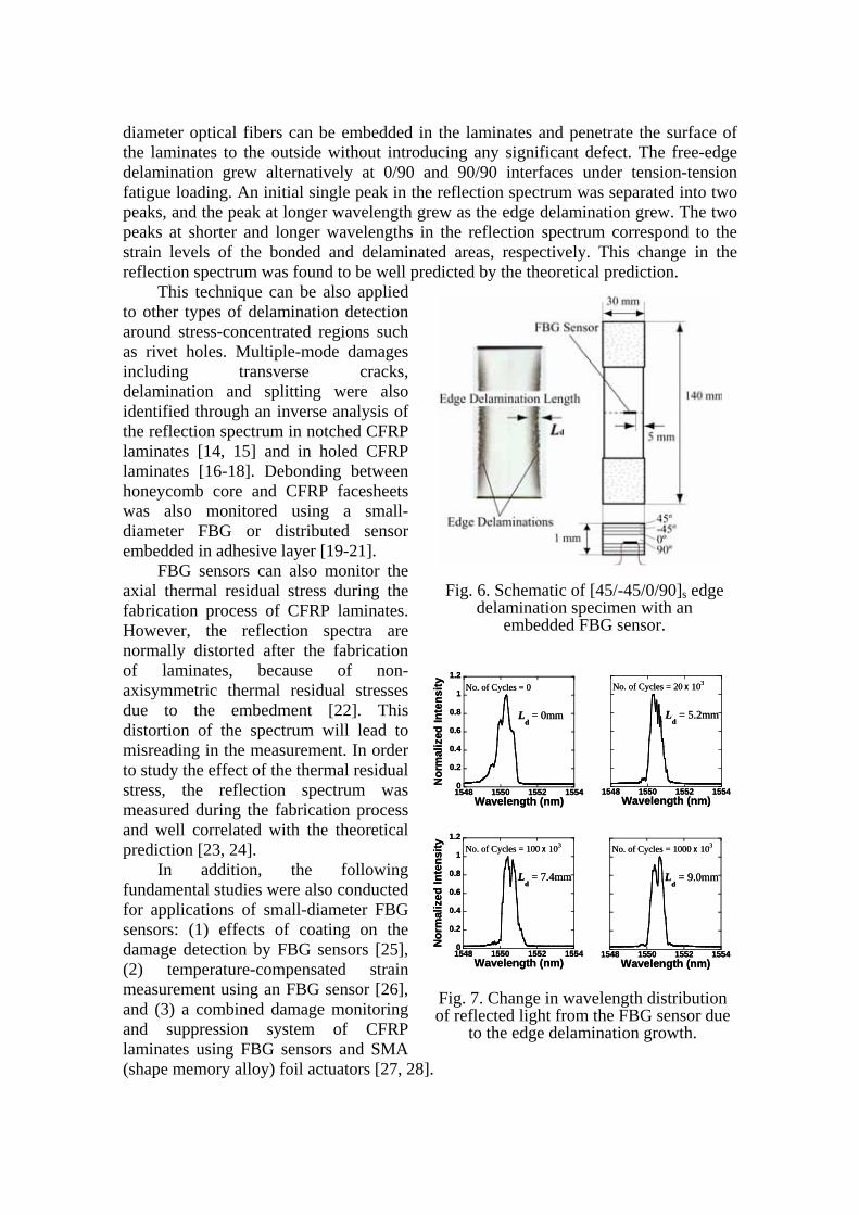
diameter optical fibers can be embedded in the laminates and penetrate the surface of the laminates to the outside without introducing any significant defect. The free-edge delamination grew alternatively at 0/90 and 90/90 interfaces under tension-tension fatigue loading. An initial single peak in the reflection spectrum was separated into two peaks, and the peak at longer wavelength grew as the edge delamination grew. The two peaks at shorter and longer wavelengths in the reflection spectrum correspond to the strain levels of the bonded and delaminated areas, respectively. This change in the reflection spectrum was found to be well predicted by the theoretical prediction.
This technique can be also applied to other types of delamination detection around stress-concentrated regions such as rivet holes. Multiple-mode damages including transverse cracks, delamination and splitting were also identified through an inverse analysis of the reflection spectrum in notched CFRP laminates [14, 15] and in holed CFRP laminates [16-18]. Debonding between honeycomb core and CFRP facesheets was also monitored using a small-diameter FBG or distributed sensor embedded in adhesive layer [19-21].
FBG sensors can also monitor the axial thermal residual stress during the fabrication process of CFRP laminates. However, the reflection spectra are normally distorted after the fabrication of laminates, because of non-axisymmetric thermal residual stresses due to the embedment [22]. This distortion of the spectrum will lead to misreading in the measurement. In order to study the effect of the thermal residual stress, the reflection spectrum was measured during the fabrication process and well correlated with the theoretical prediction [23, 24].
In addition, the following fundamental studies were also conducted for applications of small-diameter FBG sensors: (1) effects of coating on the damage detection by FBG sensors [25], (2) temperature-compensated strain measurement using an FBG sensor [26], and (3) a combined damage monitoring and suppression system of CFRP laminates using FBG sensors and SMA (shape memory alloy) foil actuators [27, 28].
Fig. 6. Schematic of [45/-45/0/90]s edge
delamination specimen with an embedded FBG sensor.
0
0.2
0.4
0.6
0.8
1
1.2
1548 1550 1552 1554
Nor
mal
ized
Inte
nsity
Wavelength (nm)
Ld = 0mm
No. of Cycles = 0
1548 1550 1552 1554Wavelength (nm)
Ld = 5.2mm
No. of Cycles = 20 x 103
0
0.2
0.4
0.6
0.8
1
1.2
1548 1550 1552 1554
Nor
mal
ized
Inte
nsity
Wavelength (nm)
Ld = 7.4mm
No. of Cycles = 100 x 103
1548 1550 1552 1554Wavelength (nm)
Ld = 9.0mm
No. of Cycles = 1000 x 103
0
0.2
0.4
0.6
0.8
1
1.2
1548 1550 1552 1554
Nor
mal
ized
Inte
nsity
Wavelength (nm)
Ld = 0mm
No. of Cycles = 0
1548 1550 1552 1554Wavelength (nm)
Ld = 5.2mm
No. of Cycles = 20 x 103
0
0.2
0.4
0.6
0.8
1
1.2
1548 1550 1552 1554
Nor
mal
ized
Inte
nsity
Wavelength (nm)
Ld = 7.4mm
No. of Cycles = 100 x 103
1548 1550 1552 1554Wavelength (nm)
Ld = 9.0mm
No. of Cycles = 1000 x 103
Fig. 7. Change in wavelength distribution of reflected light from the FBG sensor due
to the edge delamination growth.
Damage Detection in Stiffened Composite Fuselage Structure In the “R&D for Smart Material/Structure System (SMSS)” project (October 1998 to March 2003) as one of the Academic Institutions Centered Program supported by NEDO (New Energy and Industrial Technology Development Organization) Japan, two demonstrators were manufactured. One was aimed at Damage Detection and Suppression, and the other was at Noise and Vibration Reduction. These were cylindrical fuselages made of composite structures, whose length was 3 m and diameter was 1.5 m [29, 30].
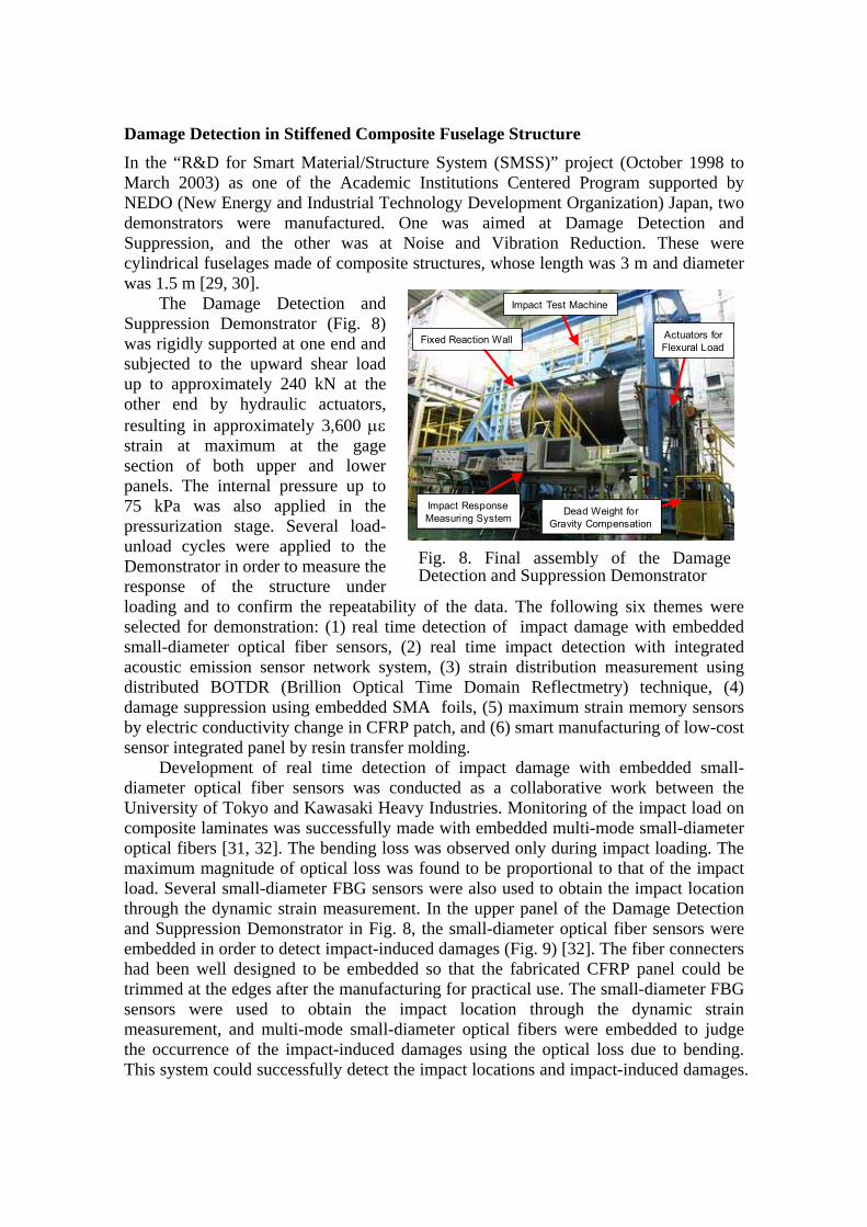
The Damage Detection and Suppression Demonstrator (Fig. 8) was rigidly supported at one end and subjected to the upward shear load up to approximately 240 kN at the other end by hydraulic actuators, resulting in approximately 3,600 µε strain at maximum at the gage section of both upper and lower panels. The internal pressure up to 75 kPa was also applied in the pressurization stage. Several load-unload cycles were applied to the Demonstrator in order to measure the response of the structure under loading and to confirm the repeatability of the data. The following six themes were selected for demonstration: (1) real time detection of impact damage with embedded small-diameter optical fiber sensors, (2) real time impact detection with integrated acoustic emission sensor network system, (3) strain distribution measurement using distributed BOTDR (Brillion Optical Time Domain Reflectmetry) technique, (4) damage suppression using embedded SMA foils, (5) maximum strain memory sensors by electric conductivity change in CFRP patch, and (6) smart manufacturing of low-cost sensor integrated panel by resin transfer molding.
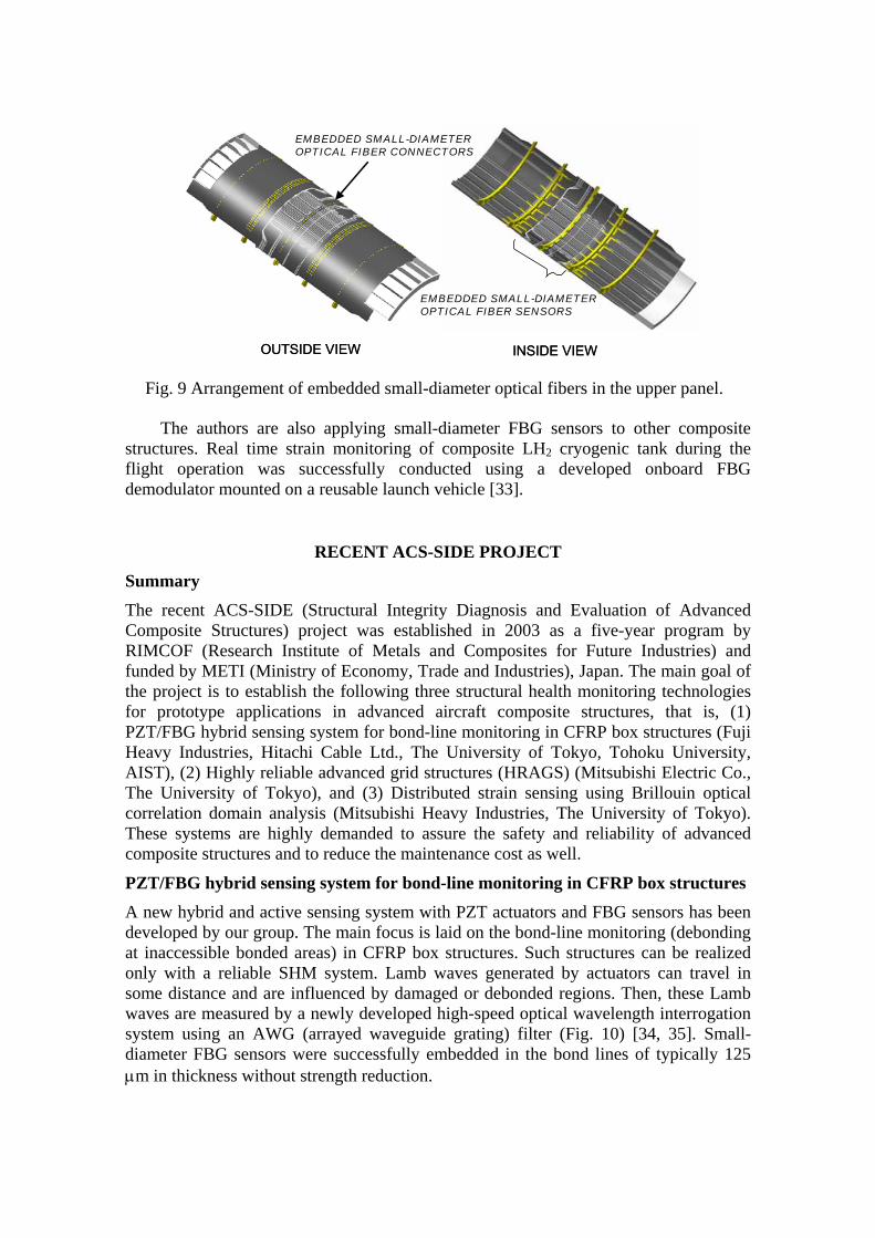
Development of real time detection of impact damage with embedded small-diameter optical fiber sensors was conducted as a collaborative work between the University of Tokyo and Kawasaki Heavy Industries. Monitoring of the impact load on composite laminates was successfully made with embedded multi-mode small-diameter optical fibers [31, 32]. The bending loss was observed only during impact loading. The maximum magnitude of optical loss was found to be proportional to that of the impact load. Several small-diameter FBG sensors were also used to obtain the impact location through the dynamic strain measurement. In the upper panel of the Damage Detection and Suppression Demonstrator in Fig. 8, the small-diameter optical fiber sensors were embedded in order to detect impact-induced damages (Fig. 9) [32]. The fiber connecters had been well designed to be embedded so that the fabricated CFRP panel could be trimmed at the edges after the manufacturing for practical use. The small-diameter FBG sensors were used to obtain the impact location through the dynamic strain measurement, and multi-mode small-diameter optical fibers were embedded to judge the occurrence of the impact-induced damages using the optical loss due to bending. This system could successfully detect the impact locations and impact-induced damages.
Impact ResponseMeasuring System
Dead Weight forGravity Compensation
Fixed Reaction Wall
Impact Test Machine
Actuators forFlexural Load
Impact ResponseMeasuring System
Dead Weight forGravity Compensation
Fixed Reaction Wall
Impact Test Machine
Actuators forFlexural Load
Fig. 8. Final assembly of the Damage Detection and Suppression Demonstrator
The authors are also applying small-diameter FBG sensors to other composite structures. Real time strain monitoring of composite LH2 cryogenic tank during the flight operation was successfully conducted using a developed onboard FBG demodulator mounted on a reusable launch vehicle [33].
RECENT ACS-SIDE PROJECT
Summary The recent ACS-SIDE (Structural Integrity Diagnosis and Evaluation of Advanced Composite Structures) project was established in 2003 as a five-year program by RIMCOF (Research Institute of Metals and Composites for Future Industries) and funded by METI (Ministry of Economy, Trade and Industries), Japan. The main goal of the project is to establish the following three structural health monitoring technologies for prototype applications in advanced aircraft composite structures, that is, (1) PZT/FBG hybrid sensing system for bond-line monitoring in CFRP box structures (Fuji Heavy Industries, Hitachi Cable Ltd., The University of Tokyo, Tohoku University, AIST), (2) Highly reliable advanced grid structures (HRAGS) (Mitsubishi Electric Co., The University of Tokyo), and (3) Distributed strain sensing using Brillouin optical correlation domain analysis (Mitsubishi Heavy Industries, The University of Tokyo). These systems are highly demanded to assure the safety and reliability of advanced composite structures and to reduce the maintenance cost as well.
PZT/FBG hybrid sensing system for bond-line monitoring in CFRP box structures A new hybrid and active sensing system with PZT actuators and FBG sensors has been developed by our group. The main focus is laid on the bond-line monitoring (debonding at inaccessible bonded areas) in CFRP box structures. Such structures can be realized only with a reliable SHM system. Lamb waves generated by actuators can travel in some distance and are influenced by damaged or debonded regions. Then, these Lamb waves are measured by a newly developed high-speed optical wavelength interrogation system using an AWG (arrayed waveguide grating) filter (Fig. 10) [34, 35]. Small-diameter FBG sensors were successfully embedded in the bond lines of typically 125 µm in thickness without strength reduction.
OUTSIDE VIEW INSIDE VIEW
EMBEDDED SMALL-DIAMETEROPTICAL FIBER SENSORS
EMBEDDED SMALL-DIAMETEROPTICAL FIBER CONNECTORS
OUTSIDE VIEW INSIDE VIEW
EMBEDDED SMALL-DIAMETEROPTICAL FIBER SENSORS
EMBEDDED SMALL-DIAMETEROPTICAL FIBER CONNECTORS
Fig. 9 Arrangement of embedded small-diameter optical fibers in the upper panel.
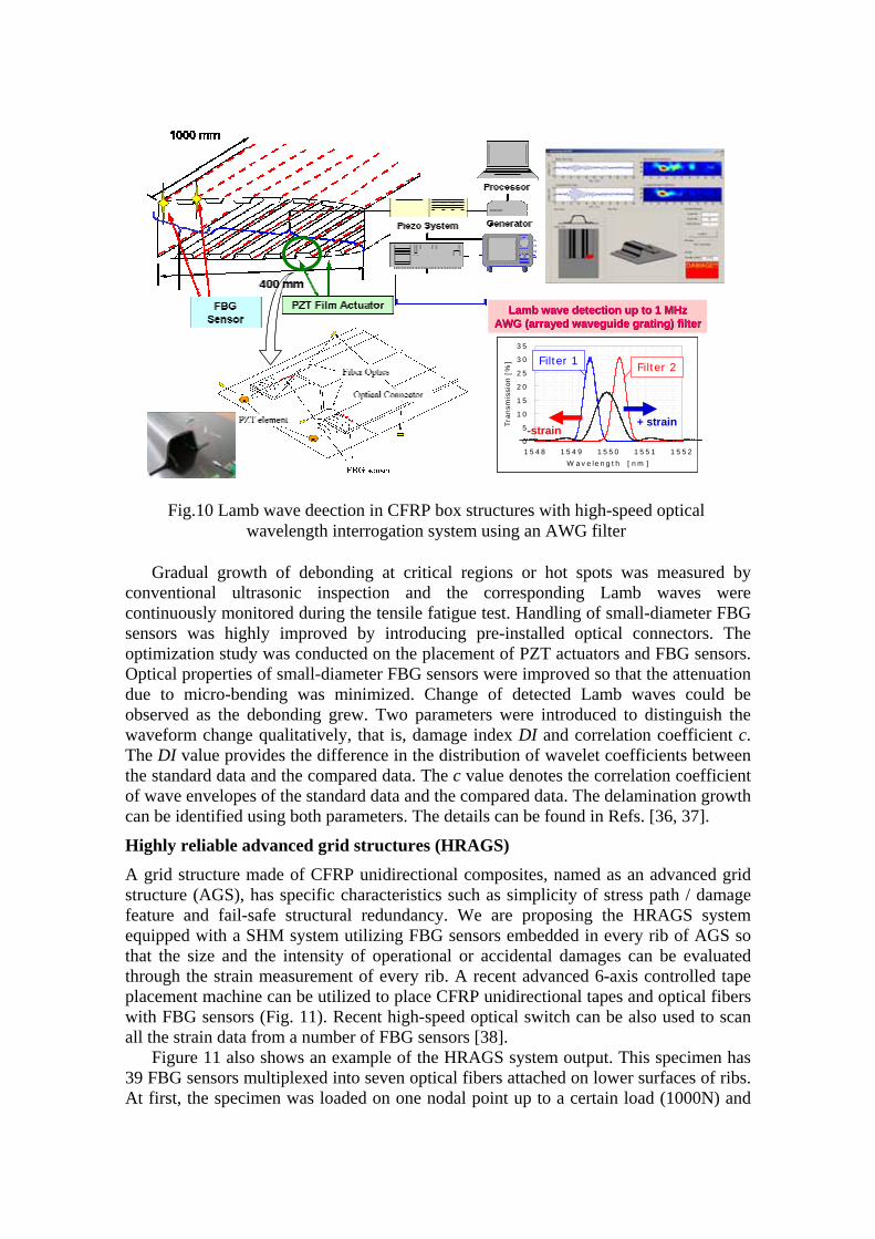
Gradual growth of debonding at critical regions or hot spots was measured by conventional ultrasonic inspection and the corresponding Lamb waves were continuously monitored during the tensile fatigue test. Handling of small-diameter FBG sensors was highly improved by introducing pre-installed optical connectors. The optimization study was conducted on the placement of PZT actuators and FBG sensors. Optical properties of small-diameter FBG sensors were improved so that the attenuation due to micro-bending was minimized. Change of detected Lamb waves could be observed as the debonding grew. Two parameters were introduced to distinguish the waveform change qualitatively, that is, damage index DI and correlation coefficient c. The DI value provides the difference in the distribution of wavelet coefficients between the standard data and the compared data. The c value denotes the correlation coefficient of wave envelopes of the standard data and the compared data. The delamination growth can be identified using both parameters. The details can be found in Refs. [36, 37].
Highly reliable advanced grid structures (HRAGS) A grid structure made of CFRP unidirectional composites, named as an advanced grid structure (AGS), has specific characteristics such as simplicity of stress path / damage feature and fail-safe structural redundancy. We are proposing the HRAGS system equipped with a SHM system utilizing FBG sensors embedded in every rib of AGS so that the size and the intensity of operational or accidental damages can be evaluated through the strain measurement of every rib. A recent advanced 6-axis controlled tape placement machine can be utilized to place CFRP unidirectional tapes and optical fibers with FBG sensors (Fig. 11). Recent high-speed optical switch can be also used to scan all the strain data from a number of FBG sensors [38].
Figure 11 also shows an example of the HRAGS system output. This specimen has 39 FBG sensors multiplexed into seven optical fibers attached on lower surfaces of ribs. At first, the specimen was loaded on one nodal point up to a certain load (1000N) and
0
5
10
15
20
25
30
35
1548 1549 1550 1551 1552
W ave leng th [nm ]
Tra
nsm
issi
on [
%] Filter 1 Filter 2
+ strain-strain
Lamb wave detection up to 1 MHzLamb wave detection up to 1 MHzAWG (arrayed waveguide grating) filterAWG (arrayed waveguide grating) filter
0
5
10
15
20
25
30
35
1548 1549 1550 1551 1552
W ave leng th [nm ]
Tra
nsm
issi
on [
%]
0
5
10
15
20
25
30
35
1548 1549 1550 1551 1552
W ave leng th [nm ]
Tra
nsm
issi
on [
%] Filter 1 Filter 2
+ strain-strain
Lamb wave detection up to 1 MHzLamb wave detection up to 1 MHzAWG (arrayed waveguide grating) filterAWG (arrayed waveguide grating) filter
Fig.10 Lamb wave deection in CFRP box structures with high-speed optical
wavelength interrogation system using an AWG filter
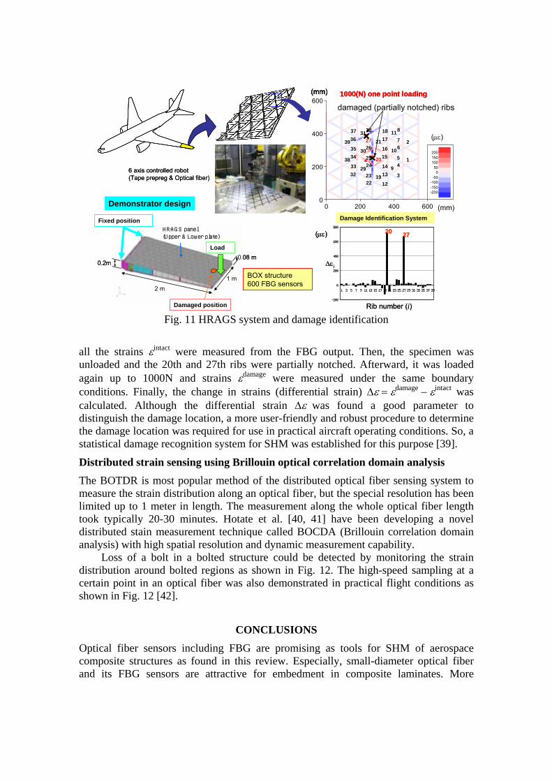
all the strains εintact were measured from the FBG output. Then, the specimen was unloaded and the 20th and 27th ribs were partially notched. Afterward, it was loaded again up to 1000N and strains εdamage were measured under the same boundary conditions. Finally, the change in strains (differential strain) ∆ε = εdamage − εintact was calculated. Although the differential strain ∆ε was found a good parameter to distinguish the damage location, a more user-friendly and robust procedure to determine the damage location was required for use in practical aircraft operating conditions. So, a statistical damage recognition system for SHM was established for this purpose [39].
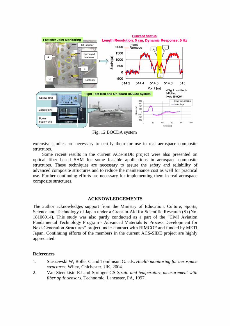
Distributed strain sensing using Brillouin optical correlation domain analysis The BOTDR is most popular method of the distributed optical fiber sensing system to measure the strain distribution along an optical fiber, but the special resolution has been limited up to 1 meter in length. The measurement along the whole optical fiber length took typically 20-30 minutes. Hotate et al. [40, 41] have been developing a novel distributed stain measurement technique called BOCDA (Brillouin correlation domain analysis) with high spatial resolution and dynamic measurement capability.
Loss of a bolt in a bolted structure could be detected by monitoring the strain distribution around bolted regions as shown in Fig. 12. The high-speed sampling at a certain point in an optical fiber was also demonstrated in practical flight conditions as shown in Fig. 12 [42].
CONCLUSIONS
Optical fiber sensors including FBG are promising as tools for SHM of aerospace composite structures as found in this review. Especially, small-diameter optical fiber and its FBG sensors are attractive for embedment in composite laminates. More
Damage Identification System
0 200 400 6000
200
400
600
-200-150-100-50
050
100150200
1332
34
22
241
2
9
10
11
19
20
21
12
14
16
3
5
7
23
15
36
4
2617
6
828 18
33
35
37
25
27
29
30
31
38
39
damaged (partially notched) ribs
(µε)
(mm)
(mm) 1000(N) one point loading
-200
0
200
400
600
800
1 3 5 7 9 11 13 15 17 19 21 23 25 27 29 31 33 35 37 39
(µε)
Rib number (i)
∆εi
20 27
6 axis controlled robot(Tape prepreg & Optical fiber)
Demonstrator design
1 m2 m
Load
Damaged position
Fixed position
0.08 m0.2m
HRAGS panel(Upper & Lower plate)
BOX structure600 FBG sensors
Damage Identification System
0 200 400 6000
200
400
600
-200-150-100-50
050
100150200
1332
34
22
241
2
9
10
11
19
20
21
12
14
16
3
5
7
23
15
36
4
2617
6
828 18
33
35
37
25
27
29
30
31
38
39
damaged (partially notched) ribs
(µε)
(mm)
(mm) 1000(N) one point loading
0 200 400 6000
200
400
600
-200-150-100-50
050
100150200
1332
34
22
241
2
9
10
11
19
20
21
12
14
16
3
5
7
23
15
36
4
2617
6
828 18
33
35
37
25
27
29
30
31
38
39
damaged (partially notched) ribs
(µε)
(mm)
(mm) 1000(N) one point loading
-200
0
200
400
600
800
1 3 5 7 9 11 13 15 17 19 21 23 25 27 29 31 33 35 37 39
(µε)
Rib number (i)
∆εi
20 27
6 axis controlled robot(Tape prepreg & Optical fiber)
Demonstrator design
1 m2 m
Load
Damaged position
Fixed position
0.08 m0.2m
HRAGS panel(Upper & Lower plate)
BOX structure600 FBG sensors
Fig. 11 HRAGS system and damage identification
extensive studies are necessary to certify them for use in real aerospace composite structures.
Some recent results in the current ACS-SIDE project were also presented on optical fiber based SHM for some feasible applications in aerospace composite structures. These techniques are necessary to assure the safety and reliability of advanced composite structures and to reduce the maintenance cost as well for practical use. Further continuing efforts are necessary for implementing them in real aerospace composite structures.
ACKNOWLEDGEMENTS The author acknowledges support from the Ministry of Education, Culture, Sports, Science and Technology of Japan under a Grant-in-Aid for Scientific Research (S) (No. 18106014). This study was also partly conducted as a part of the “Civil Aviation Fundamental Technology Program - Advanced Materials & Process Development for Next-Generation Structures” project under contract with RIMCOF and funded by METI, Japan. Continuing efforts of the members in the current ACS-SIDE project are highly appreciated.
References 1. Staszewski W, Boller C and Tomlinson G. eds. Health monitoring for aerospace
structures, Wiley, Chichester, UK, 2004. 2. Van Steenkiste RJ and Springer GS Strain and temperature measurement with
fiber optic sensors, Technomic, Lancaster, PA, 1997.
Current StatusLength Resolution: 5 cm, Dynamic Response: 5 Hz
Fastener
A
C
B
OF sensor
Removedfastener
430mm
460m
m
Power supply unit
Control unit
Optical Unit
-500
0
500
1000
1500
2000
514.2 514.4 514.6 514.8 515Point [m]
Stra
in [µε]
IntactRemove A C
B
Fastener Joint Monitoring
-300-200-100
0100200300400
0 20 40 60 80 100
Time [sec]
Stra
in [µε]
Strain from BOCDA
Strain Gage
<Flight condition>Pull upAlt: 15,000ft
Flight Test Bed and On-board BOCDA system
Current StatusLength Resolution: 5 cm, Dynamic Response: 5 Hz
Fastener
A
C
B
OF sensor
Removedfastener
430mm
460m
m
Power supply unit
Control unit
Optical Unit
430mm
460m
m
Power supply unit
Control unit
Optical Unit
-500
0
500
1000
1500
2000
514.2 514.4 514.6 514.8 515Point [m]
Stra
in [µε]
IntactRemove A C
B
Fastener Joint Monitoring
-300-200-100
0100200300400
0 20 40 60 80 100
Time [sec]
Stra
in [µε]
Strain from BOCDA
Strain Gage
<Flight condition>Pull upAlt: 15,000ft
Flight Test Bed and On-board BOCDA system
Fig. 12 BOCDA system
3. Mrad N, Optical fiber sensor technology: Introduction and evaluation and application. in Encyclopedia of Smart Materials, Vol. 2, John Wiley & Sons, Inc., New York, pp 715-737, 2002.
4. Kersey AD, Davis MA, Patrick HJ, LeBlanc M, Koo KP, Askins CG, Putnam MA, and Friebele EJ. Fiber grating sensors, Journal of Lightwave Technol., Vol. 15, No. 8, pp 1442-1463, 1997.
5. Satori K, Fukuchi K, Kurosawa Y, Hongo A, and Takeda N. Polyimide-coated small-diameter optical fiber sensors for embedding in composite laminate structures, Proc. SPIE, Vol. 4328, pp 285-294, 2001.
6. Okabe Y, Yashiro S, Kosaka T, and Takeda N. Detection of transverse cracks in CFRP composites using embedded fiber Bragg grating sensors. Smart Mater. Struct., Vol. 9, No. 6, pp 832-838, 2000.
7. Okabe Y., Mizutani,T, Yashiro S, and Takeda N. Detection of microscopic damages in composite laminates with embedded small-diameter fiber Bragg grating sensors. Comp. Sci. Technol., Vol. 62, No. 7-8, pp 951-958, 2002.
8. Mizutani T, Okabe Y, and Takeda, N. Quantitative evaluation of transverse cracks in carbon fiber reinforced plastic quasi-isotropic laminates with embedded small-diameter fiber Bragg grating sensors. Smart Mater. Struct., 2003, 12(6), 898-903.
9. Okabe Y, Tsuji R, and Takeda N. Application of chirped fiber Bragg grating sensors for identification of crack locations in composites. Compos. Part A - Appl. S., , Vol. 35, No. 1, pp 59-65, 2004.
10. Takeda S, Okabe Y, and Takeda N. Delamination detection in CFRP laminates with embedded small-diameter fiber Bragg grating sensors. Compos. Part A - Appl. S., Vol. 33, No. 7, pp 971-980, 2002.
11. Takeda, S., Okabe, Y., Yamamoto, T. and Takeda, N. Detection of edge delamination in CFRP laminates under cyclic loading using small-diameter FBG sensors. Comp. Sci. Technol., 2003, 63(13), 1885-1894.
12. Takeda S, Minakuchi S, Okabe Y, and Takeda N. Delamination monitoring of laminated composites subjected to low-velocity impact using small-diameter FBG sensors. Compos. Part A - Appl. S., Vol. 36, No. 7, pp 903-908, 2005.
13. Takeda S, Yamamoto T, Okabe Y, and Takeda N. Debond monitoring of composite repair patches using embedded small-diameter FBG sensors, Smart Mater. Struct., Vol. 16, pp 763-770, 2007.
14. Yashiro S, Takeda N., Okabe T, and Sekine H. A new approach to predicting multiple damage states in composite laminates with embedded FBG sensors. Comp. Sci. Technol., Vol. 65, No. 3-4, pp 659-667, 2005.
15. Takeda N, Yashiro S, and Okabe T. Estimation of the damage patterns in notched laminates with embedded FBG sensors. Comp. Sci. Technol., Vol. 66, No. 5, pp 684-693, 2006.
16. Yashiro S, Okabe T, and Takeda N. Damage identification in a holed CFRP laminate using a chirped fiber Bragg grating sensor. Compos. Sci. Technol., Vol. 67, pp 286-295, 2007.
17. Yashiro S, Okabe T, Toyama N, and Takeda N. Monitoring damage in holed CFRP laminates using embedded chirped FBG sensors. Int. J. Solids Struct, Vol. 44, pp 603-613, 2007.
18. Yashiro S, Murai K, Okabe T, and Takeda N. Numerical study for identifying damage in open-hole composites with embedded FBG sensors and its application to experiment results. Adv Compos. Mater., Vol. 16, pp 1370-1378, 2007.
19. Minakuchi S, Okabe Y, and Takeda N. Real-time detection of debonding between honeycomb core and facesheet using a small-diameter FBG sensor embedded in adhesive layer. J. Sandwich Struct. Mater., Vol. 9, No. 1, pp 9-33, 2007.
20. Minakuchi S, Okabe Y, and Takeda N. ‘Segment-wise model’ for theoretical simulation of barely visible indentation damage in composite sandwich beams: Part I - Formulation. Compos. Part A - Appl. S., Vol. 39, No. 1, pp 133-144, 2008.
21. Minakuchi S, Okabe Y, and Takeda N. ‘Segment-wise model’ for theoretical simulation of barely visible indentation damage in composite sandwich beams: Part II – Experimental verification and discussion. Compos. Part A - Appl. S., Vol. 38, No. 12, pp 2443-2450, 2007.
22. Guemes JA and Menendez JM. Response of Bragg grating fiber-optic sensors when embedded in composite laminates. Comp. Sci. Technol., Vol. 62, No. 7-8, pp 959-966, 2002.
23. Okabe Y, Yashiro S, Tsuji R, Mizutani T, and Takeda N. Effects of thermal residual stress on the reflection spectrum from fiber Bragg grating sensors embedded in CFRP laminates. Compos. Part A - Appl. S., Vol. 33, No. 7, pp 991-999, 2002.
24. Okabe Y, Tsuji R, and Takeda N. Measurement of non-axisymmetric thermal residual strain in CFRP laminates using FBG sensors. Trans. Japan Soc. Comp. Mater., Vol. 30, No. 5, pp 199-206, 2004 (in Japanese).
25. Okabe Y, Tanaka N, and Takeda N. Effect of fiber coating on crack detection in carbon fiber reinforced plastic composites using fiber Bragg grating sensors. Smart Mater. Struct., Vol. 11, No. 6, pp 892-898, 2002.
26. Tanaka N, Okabe Y, and Takeda N. Temperature-compensated strain measurement using fiber Bragg grating sensors embedded in composite laminates. Smart Mater. Struct., Vo. 12, No. 6, pp 940-946, 2003.
27. Taketa I, Amano M, Okabe Y, and Takeda N. Damage detection and suppression system of CFRP laminates with FBG sensor and SMA actuator. Trans. Mater. Res. Soc. Japan, Vol. 28, No. 3, pp 675-678, 2003.
28. Amano M, Okabe Y, and Takeda N. Evaluation of crack suppression effect of TiNi SMA foil embedded in CFRP cross-ply laminates with embedded small-diameter FBG sensor, JSME Inter. J., Series A, Vol. 48, No. 4, pp 443-450, 2005.
29. Tajima N, Sakurai T, Sasajima M, Takeda N, and Kishi T. Overview of the demonstrator program in Japanese smart material and structure system project. Adv. Comp. Mater., Vol. 13, No. 3, pp 3-5, 2004.
30. Takeda N, Tajima N, Sakurai T, and Kishi T. Recent advances in composite fuselage demonstration program for damage and health monitoring in Japan. Struct. Cont. Health Monitoring, Vol. 12, No. 3-4, pp 245-255, 2005.
31. Tsutsui H, Kawamata A, Sanda T, and Takeda N. Detection of impact damage of stiffened composite panels using embedded small-diameter optical fibers. Smart Mater. Struct., Vol. 13, No. 6, pp 1284-1290, 2004.
32. Tsutsui H, Kawamata A., Kimoto J, Isoe A, Hirose Y, Sanda T, and Takeda N. Impact damage detection system using small-diameter optical fiber sensors embedded in CFRP laminate structures. Adv. Comp. Mater., Vol. 13, No. 3, pp 43-55, 2004.
33. Mizutani T, Takeda N, and Takaya H. On-board strain measurement of a cryogenic composite tank mounted on a reusable rocket using FBG sensors. Struct. Health Monitoring, Vol. 5, No. 3, pp 205-214, 2006.
34. Ogisu, T, Shimanuki M, Kiyoshima S, Okabe Y, and Takeda N. Feasibility studies on active damage detection for CFRP aircraft bonding structures. Adv. Compos. Mater., Vol. 15, No. 2, pp 153-173, 2006.
35. Takeda N, Okabe Y, Kuwahara J, Kojima S, and Ogisu T. Development of smart composite structures with small-diameter fiber Bragg grating sensors for damage detection: quantitative evaluation of delamination length in CFRP laminates using Lamb wave sensing. Comp. Sci. Technol., Vol. 65, No. 15-16, pp 2575-2587, 2005.
36. Ogisu T, Shimanuki M, Yoneda H, Okabe, Y, Kuwahara J, Takeda N, and Sakurai T. Damage growth monitoring for a bonding layer of the aircraft bonding structure. Proc. SPIE, Vol. 6171, 2006, 61710C.
37. Okabe Y, Kuwahara J, Takeda N, Ogisu T., Kojima, S. and Komatsuzaki, S. Evaluation of debonding progress in composite bonded structures by ultrasonic wave sensing with fiber Bragg grating sensors. Proc. SPIE, Vol. 6179, 2006, 61790G.
38. Takeya H, Ozaki T, Takeda N, and Tajima N. Damage detection of advanced grid structure using multi-point FBG sensors. Proc. SPIE, Vol. 6171, SPIE, 2006, 61710D.
39. Amano M, Okabe Y, Takeda N, and Ozaki T. Structural health monitoring of an advanced grid structure with embedded fiber Bragg grating sensors. Struct. Health Monitoring, Vol. 6, No. 4, pp 309-324, 2007.
40. Hotate K and Kashiwagi M. High spatial resolution reflectometry for optical subscriber networks by synthesis of optical coherence function with measurement range enhancement. IEICE Trans. on Electronics., E86-C(2), pp 213-217, 2003.
41. Hotate K. Fiber sensor technology today. Jpn. J. Appl. Phys., Vol. 45, No. 8B, pp 6616-6625, 2006.
42. Yari T, Ishioka M, Nagai K, and Sakurai T. An application test using Brillouin optical correlation base analysis method for aircraft structural health monitoring. Proc. SPIE, Vol. 6167, 2006, 61670D.
Top Related