


Languages
Pages
Legal


PAUL SCHERRER INSTITUT
LABORATORY FOR ASTROPHYSICSvPASTR
OI
PROTONIRRADIATIONFACILITYPROTON IRRADIATION FACILITY
4Two major changes in 2000
4Radiation effects in electronics
4Simulation of proton space environment
4Source of mono-energetic proton beams
4Calibration of particle detectors
4Operates since 1992
4User friendly and commonly available
MAIN FEATURES REMINDER
Energy range:50-300 MeV (9-60 MeV LI) - PKC26-71 MeV - NEB
Maximum beam flux:105-108 p/sec/cm2 - PKC2109 p/sec/cm2 - NEB
Beam profiles:Gaussian σ ≅ 6 cm or flat - PKC2Flat φ ≅ 6.0 cm - NEB
Irradiation takes place in air
Sample mounting frame attachedon XY table (can be rotated)
Sample test board as inSEU-Brookhaven and HIF-Brussel
Automated Data Acquisition System
PAUL SCHERRER INSTITUT
LABORATORY FOR ASTROPHYSICSvPASTR
OI
PROTONIRRADIATIONFACILITYOPERATION in 2000 - SUMMARY
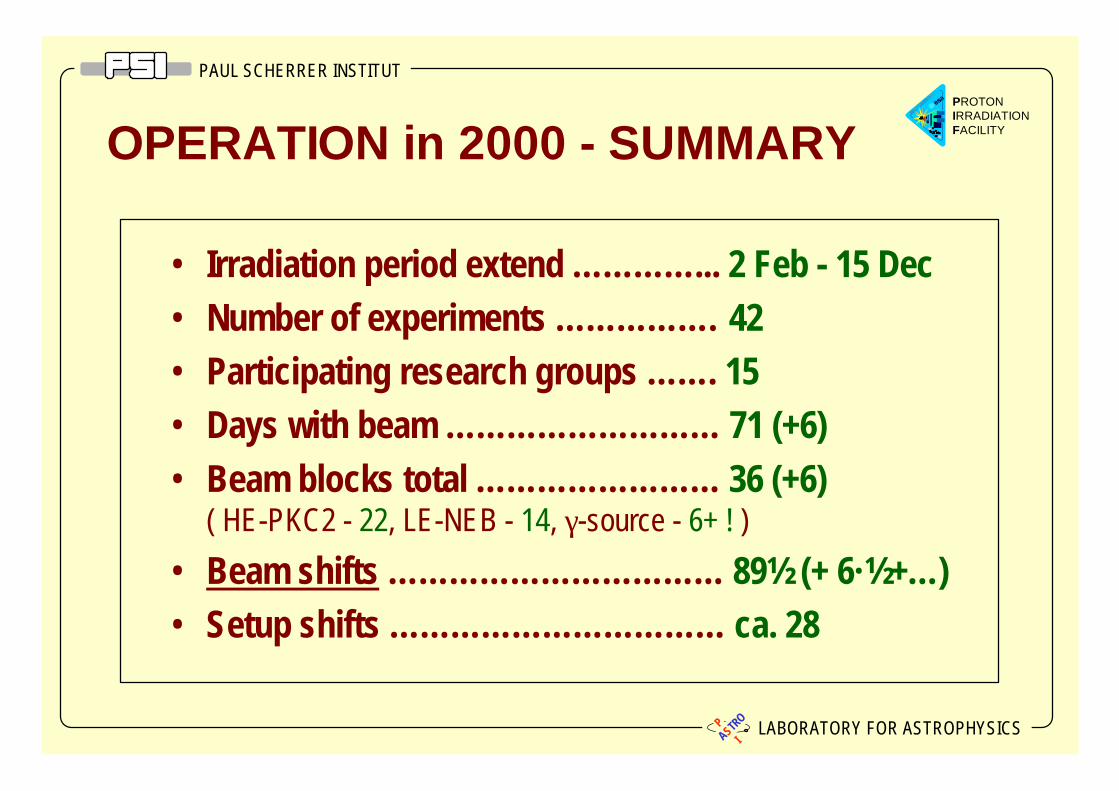
• Irradiation period extend … … … … ... 2 Feb - 15 Dec• Number of experiments … … … … … . 42• Participating research groups … … . 15• Days with beam … … … … … … … … … 71 (+6)• Beam blocks total … … … … … … … … 36 (+6)
( HE-PKC2 - 22, LE-NEB - 14, γ-source - 6+ ! )
• Beam shifts … … … … … … … … … … … 89½ (+ 6·½ +… )• Setup shifts … … … … … … … … … … … ca. 28

PAUL SCHERRER INSTITUT
LABORATORY FOR ASTROPHYSICSvPASTR
OI
PROTONIRRADIATIONFACILITYPSI Selected Experimental Facilities
PIF Station PKC2High Energies
PIF Station NEBLow Energies
Old PIF NA2
Old PIF OPTIS
PKC2 Hall with PIF
PIF
PIREX
PIF Barrack
PAUL SCHERRER INSTITUT
LABORATORY FOR ASTROPHYSICSvPASTR
OI
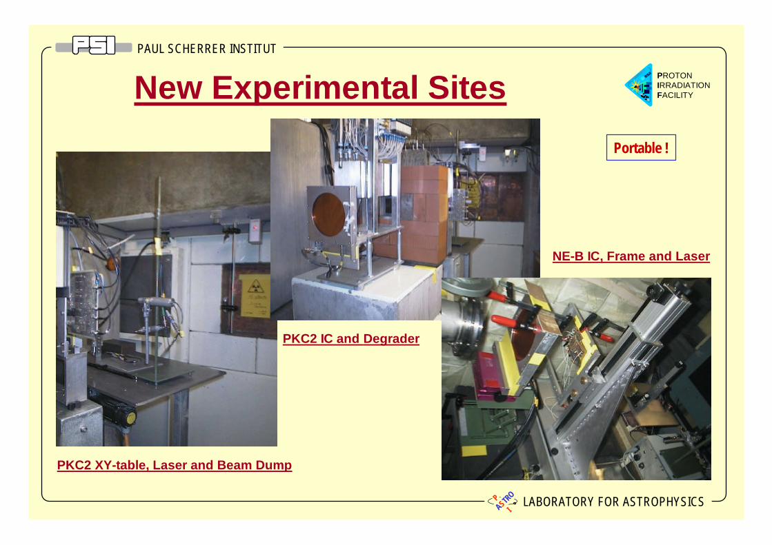
PROTONIRRADIATIONFACILITYNew Experimental Sites
PKC2 XY-table, Laser and Beam Dump
NE-B IC, Frame and Laser
Portable !
PKC2 IC and Degrader

PAUL SCHERRER INSTITUT
LABORATORY FOR ASTROPHYSICSvPASTR
OI
PROTONIRRADIATIONFACILITY
♦ ESA / ESTEC, EU
♦ PSI, Villigen
♦ ETH, Zürich
♦ University of Bern
♦ ABB Semiconductors, Lenzburg
♦ Contraves Space, Zürich
♦ CERN, Genf
PIF USERS in 2000
♦ HIREX, France
♦ TRAD, France
♦ ALCATEL, France and Norway
♦ ASTRIUM, France and Germany
♦ SAAB Ericson Space, Sweden
♦ GSFC / Uni Berkeley, USA
♦ Marconi Applied Technologies, UK

PAUL SCHERRER INSTITUT
LABORATORY FOR ASTROPHYSICSvPASTR
OI
PROTONIRRADIATIONFACILITYESA EXPERIMENTS at PIF in 2000
WORK ORDER 15
• Proton irradiation of THOMSON photodiodes and MIPAD photodiodes
• Proton irradiation of SAW filters
• Proton irradiation of non-linear crystals
• Proton irradiation of various laser diodes
WORK ORDER 16
• Proton irradiation of ACTEL FPGA - RT54SX16
• Proton irradiation of various Optocouplers types
• Proton irradiation of SIEMENS LabTop
• Proton irradiation of various SRAM types

PAUL SCHERRER INSTITUT
LABORATORY FOR ASTROPHYSICSvPASTR
OI
PROTONIRRADIATIONFACILITYPIF EXPERIMENTS BY OTHER USERS
• IREM radiation monitor calibration for INTEGRAL
• SREM calibration for PROBA and ROSETTA
• Radiation damage of various CCDs
• Activation measurement of Ta, Ti, Cu, W, and Al
• Radiation effects in power MOSFETs
• Radiation damage in novel solar cell technologies
• Dose effects in power supplies for CMS muon chamber and calorimeter
• Proton test of video-chain electronics (compressor and emitter)
• SEU characterisation of various electronic devices
• Proton test of Space Robotronic Controller
• Proton irradiation of AD Converter
• Gamma/electron tests of SREMs

PAUL SCHERRER INSTITUT
LABORATORY FOR ASTROPHYSICSvPASTR
OI
PROTONIRRADIATIONFACILITYProton Irradiation of THOMSON and
MIPAD photodiodes ( ESA ESTEC )
DUTs -12 THOMSON photodiodes with various epitaxial layers,
6 THOMSON photodiode arrays 2 MIPAS photodiodes 1 MIPAS laser diodeSetup -
Several samples irradiated simultaneously if possible.Devices unbiased, grounded, facing beam.
Exposures -Two campaigns performed.Energy: 6 and 30 MeVFluency: from 107 to 1012 p/cm2
Fluxes: from 106 up to 5·108 p/cm2
Analysis -Performed by ESA-ESTEC
Irradiation setup in PIF OPTIS facility
PAUL SCHERRER INSTITUT
LABORATORY FOR ASTROPHYSICSvPASTR
OI
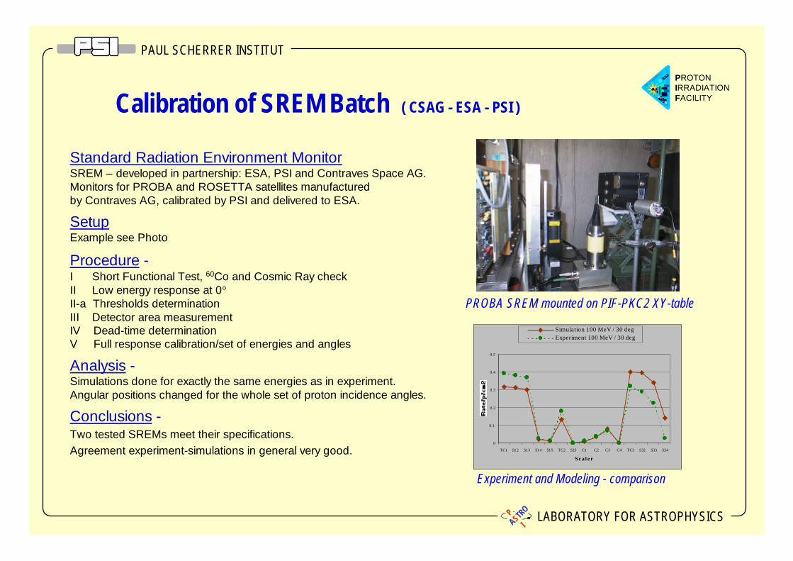
PROTONIRRADIATIONFACILITYCalibration of SREM Batch ( CSAG - ESA - PSI )
Standard Radiation Environment MonitorSREM – developed in partnership: ESA, PSI and Contraves Space AG.Monitors for PROBA and ROSETTA satellites manufacturedby Contraves AG, calibrated by PSI and delivered to ESA.
SetupExample see Photo
Procedure -I Short Functional Test, 60Co and Cosmic Ray checkII Low energy response at 0°II-a Thresholds determinationIII Detector area measurementIV Dead-time determinationV Full response calibration/set of energies and angles
Analysis -Simulations done for exactly the same energies as in experiment.Angular positions changed for the whole set of proton incidence angles.
Conclusions -Two tested SREMs meet their specifications.Agreement experiment-simulations in general very good.
PROBA SREM mounted on PIF-PKC2 XY-table
Experiment and Modeling - comparison
0
0.1
0.2
0.3
0.4
0.5
TC1 S12 S13 S14 S15 TC2 S25 C1 C2 C3 C4 TC3 S32 S33 S34
S c a l e r
Simulation 100 MeV / 30 degExperiment 100 MeV / 30 deg

PAUL SCHERRER INSTITUT
LABORATORY FOR ASTROPHYSICSvPASTR
OI
PROTONIRRADIATIONFACILITY
HESSI - High Energy Solar Spectroscopic Imager Launch - 28 March 2001Activation - mostly metals surrounding Ge-spectrometerRadiation - predominantly protons in SAA
Gamma spectrum from Sn-Fe-Ta (1g) exposed to SAA proton spectrum. F=5.8•1010 p/cm2 - 100 days in orbit;
Background Studies for HESSI Project -SAA Induced Radioactivity ( PSI - GSFC - UCB )
Irradiated elements - Al, Ti, Cu, W and graded-Z shield plates: Sn-Fe-Ta (20x10x2 mm3)
Exposures - Single energies: 50, 100, 200 MeV, SAA spectrum: 30-300 MeV in 8 bins
Analysis - Sn-Fe-Ta : 40 gamma ray lines found from 18 radioisotopes with T1/2 from 8 min to 2 days. Total activity after SAA exposure test A=147 Bq/g
Activity changes during the flight - activation gain during SAA passing
0 250 500 750 1000 1250 1500
1
10
100
Cou
nts
/ cha
nnel
/g
Energy / keV
Sn-Fe-Ta activation in SAA
0 10 20 30 40 50 60 700
50
100
150
200
W A
ctiv
ity /
Bq/
kg
Time in orbit / hours

PAUL SCHERRER INSTITUT
LABORATORY FOR ASTROPHYSICSvPASTR
OI
PROTONIRRADIATIONFACILITY
Solar Cells manufactured by ETHZ
Proton Radiation Hardness Characterizationof Solar Cells - ( ETHZ-PSI )
Irradiated elements -Solar cells in blocks of 12,
Al shielding to determine energy
Setup and Exposures -Energy: 0, 5, 10, 15 MeV (all at once using degraders)
Fluency: 1011, 1012, 1013 p/cm2
4 cells exposed to single energy and fluency
Analysis -Done by ETH Zurich;
Results -Preliminary data promising (TBP),
New measurements are planned
PAUL SCHERRER INSTITUT
LABORATORY FOR ASTROPHYSICSvPASTR
OI
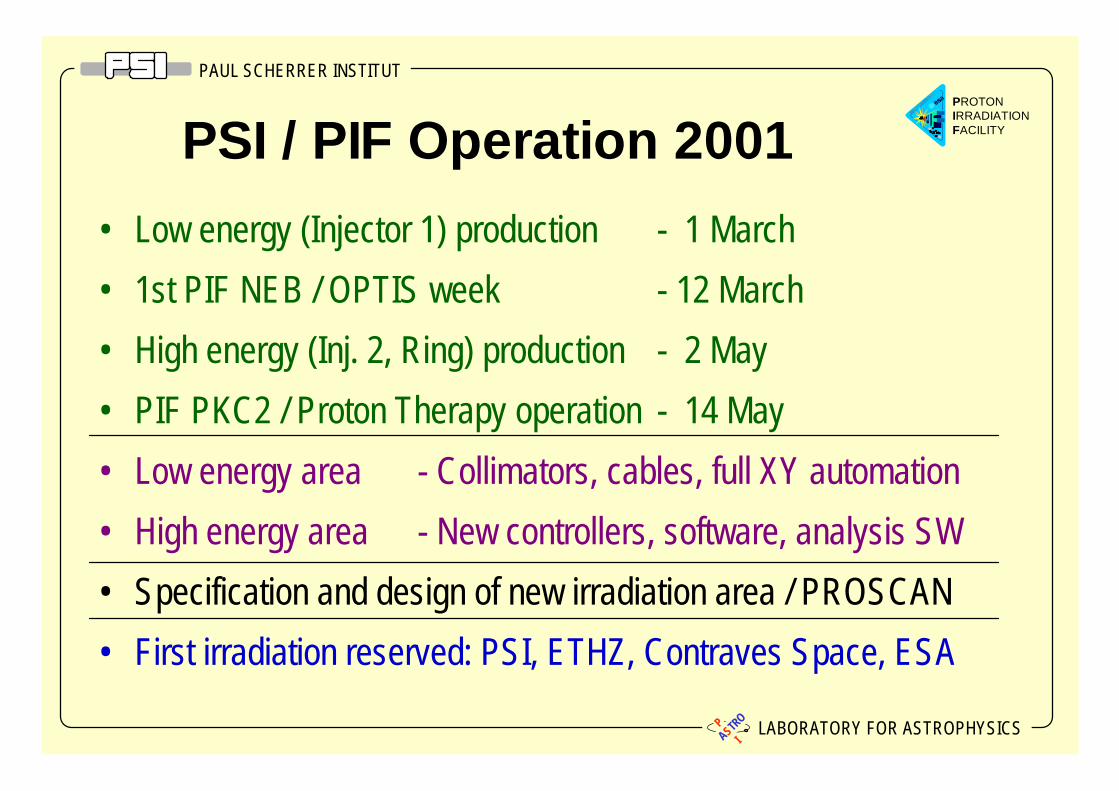
PROTONIRRADIATIONFACILITYPSI / PIF Operation 2001
• Low energy (Injector 1) production - 1 March
• 1st PIF NEB / OPTIS week - 12 March
• High energy (Inj. 2, Ring) production - 2 May
• PIF PKC2 / Proton Therapy operation - 14 May
• Low energy area - Collimators, cables, full XY automation
• High energy area - New controllers, software, analysis SW
• Specification and design of new irradiation area / PROSCAN
• First irradiation reserved: PSI, ETHZ, Contraves Space, ESA

PAUL SCHERRER INSTITUT
LABORATORY FOR ASTROPHYSICSvPASTR
OI
PROTONIRRADIATIONFACILITYNew Biomedical Cyclotron Project -
PROSCAN
New PIF Area
NA - HALL
Cyclotron
Biomedical FacilitiesOPTISGANTRY 2GANTRY 1 (existing)

PAUL SCHERRER INSTITUT
LABORATORY FOR ASTROPHYSICSvPASTR
OI
PROTONIRRADIATIONFACILITY
Start of project
Modifications of shielding
Civil works at the existing hall
Adaption of PIREX
Installation/commissioning cyclotron
Installation/commissioning beamlines
Start up Gantry I
Construction medical pavilion
Installation/commissioning OPTIS
Installation/commissioning PIF
End of project
Contract for cyclotron
200520042003200220012000
Utility building
Beamline for Gantry II
Master Schedule
PAUL SCHERRER INSTITUT
LABORATORY FOR ASTROPHYSICSvPASTR
OI
PROTONIRRADIATIONFACILITY
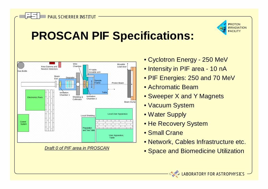
PROSCAN PIF Specifications:
• Cyclotron Energy - 250 MeV• Intensity in PIF area - 10 nA• PIF Energies: 250 and 70 MeV• Achromatic Beam• Sweeper X and Y Magnets• Vacuum System• Water Supply• He Recovery System• Small Crane• Network, Cables Infrastructure etc.• Space and Biomedicine UtilizationDraft 0 of PIF area in PROSCAN
D e g r a d e rS h i e l d i n g &C o l l i m a t o r
W i r eC h a m b e rX Y - t a b l em o v a b l e a r m
I o n i s a t i o nC h a m b e r 2Sample F r a m eT a b l eB e a mE x i t
L o c a l S h i e l d i n gControl S y s t e mPreparation
E l e c t r o n i c s R a c k
A r e a G a m m a a n dN e u t r o n D e t e c t o r sG a s B o t t l e
I o n i s a t i o nC h a m b e r 1
Degrader
Shielding &Collimator
WireChamber
XY-tablemovable arm
IonisationChamber 2
Sample Frame
Table
Movable Lead-door
Beam Dump
BeamExit
Local User ApparatusLocal Shielding
Proton Beam
Control System
User Apparatus, Table
Preparation and Test Table
Electronics Rack
Area Gamma andNeutron Detectors
Gas Bottle
IonisationChamber 1
Top Related