


Languages
Pages
Legal

STEEL BUILDINGS IN EUROPE
Multi-Storey Steel Buildings
Part 1: Architect’s Guide

Multi-Storey Steel Buildings
Part 1: Architect’s Guide

1 - ii
Part 1: Architect’s Guide
FOREWORD
This publication is the first part of the design guide, Multi-Storey Steel Buildings.
The 10 parts in the Multi-Storey Steel Buildings guide are:
Part 1: Architect’s guide
Part 2: Concept design
Part 3: Actions
Part 4: Detailed design
Part 5: Joint design
Part 6: Fire Engineering
Part 7: Model construction specification
Part 8: Description of member resistance calculator
Part 9: Description of simple connection resistance calculator
Part 10: Guidance to developers of software for the design of composite beams
Multi-Storey Steel Buildings is one of two design guides. The second design guide is Single-Storey Steel Buildings.
The two design guides have been produced in the framework of the European project “Facilitating the market development for sections in industrial halls and low rise buildings (SECHALO) RFS2-CT-2008-0030”.
The design guides have been prepared under the direction of Arcelor Mittal, Peiner Träger and Corus. The technical content has been prepared by CTICM and SCI, collaborating as the Steel Alliance.
1 - i

Part 1: Architect’s Guide
1 - ii
Part 1: Architect’s Guide
Contents Page No
FOREWORD i
SUMMARY v
1 INTRODUCTION 1
2 FUNCTIONAL QUALITIES 3 2.1 Architectural creativity and flexibility 3 2.2 Prefabrication – Industrialised building systems 5 2.3 An evolving art 6 2.4 Extending and refurbishment 6
3 STEEL – MATERIAL AND PRODUCTS 9 3.1 Steel the material 9 3.2 Steel products 9
4 BASIS OF GOOD DESIGN: THE STRUCTURE 13 4.1 The load-bearing system 13 4.2 Bracings 19 4.3 Floors 22 4.4 Connections 26 4.5 Summary 29
5 BASIS OF GOOD DESIGN: THE ENVELOPE 30 5.1 Façades 30 5.2 Roofing systems 36
6 OTHER FACTORS FOR GOOD DESIGN 41 6.1 Behaviour during an earthquake 41 6.2 Behaviour during a fire 42 6.3 Acoustic performance 48 6.4 Thermal performance 52 6.5 Durability of steel structures 53 6.6 Service integration 57
7 STEEL CONSTRUCTION AND SUSTAINABILITY 59 7.1 Life cycle 60 7.2 Advantages of steel products for construction 60 7.3 Steel-intensive solutions for buildings 61
8 CONCLUSION 64
REFERENCES 65
1 - iii

Part 1: Architect’s Guide
1 - iv
Part 1: Architect’s Guide
SUMMARY
For centuries, steel has demonstrated all its advantages as a construction material for use in famous buildings in the world, but steel is not only a material that delivers technical prowess. It has so many qualities that simply make it the preferred material of architects, especially for multi-storey buildings. This publication has been drafted by architects for architects. It provides information on the material and on the industrial components. It gives the bases of good practice in order to achieve maximum benefit in using steel, in terms of structural behaviour of steel frames, the building envelope, acoustic and thermal performances and sustainable construction.
1 - v

Part 1: Architect’s Guide
1 - vi
Part 1: Architect’s Guide
1 INTRODUCTION
What do Claude Perrault’s Louvre colonnades (1670), Mies van der Rohe’s Lake Shore Drive apartment towers (1951), Soufflot’s Church of St. Genevieve in Paris (1759), Piano and Roger’s Georges Pompidou Centre (1977) and Jean Nouvel’s Hôtel Industriel in Pantin (1990) all have in common? Each one bears testimony to the great epic of metal in construction.
Of course, the transformation from iron used as structural reinforcement and decoration to the light and airy steel frame which we know today was a very long process. It encompassed no less than 300 years of historical progress, innovation, imagination and creativity: on the part of architects, who introduced new shape grammars with cast iron, iron and then steel; on the part of engineers, whose technical expertise and imagination played a major role in the building of new structures which were once thought of as impossible, even utopian; and on the part of manufacturers, who have worked tirelessly on the development of new materials and products.
Three hundred years of passion for metal: a passion which has been expressed in different ways. Cast iron, once used in buildings, was expensive, heavy and brittle, and provided a very special kind of structural reinforcement dictated by the style of that period: enormous proportions, with iron staples used to hold together blocks of stone to ensure the building’s stability.
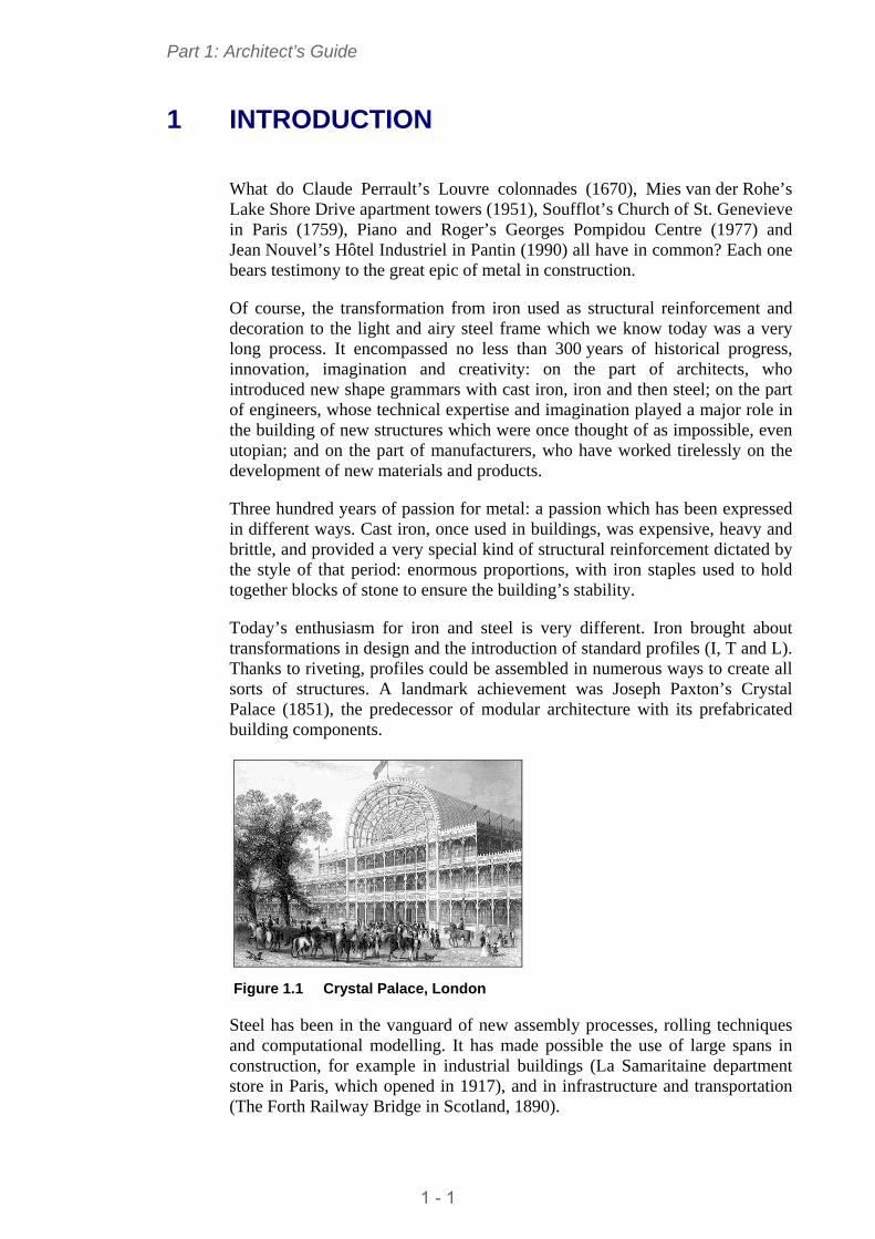
Today’s enthusiasm for iron and steel is very different. Iron brought about transformations in design and the introduction of standard profiles (I, T and L). Thanks to riveting, profiles could be assembled in numerous ways to create all sorts of structures. A landmark achievement was Joseph Paxton’s Crystal Palace (1851), the predecessor of modular architecture with its prefabricated building components.
Figure 1.1 Crystal Palace, London
Steel has been in the vanguard of new assembly processes, rolling techniques and computational modelling. It has made possible the use of large spans in construction, for example in industrial buildings (La Samaritaine department store in Paris, which opened in 1917), and in infrastructure and transportation (The Forth Railway Bridge in Scotland, 1890).
1 - 1
Part 1: Architect’s Guide
Steel is not just a material aimed at technical prowess! It has many qualities that make it the preferred material for architects. It is economical and provides great mechanical functionality; it permits the design of structures which are graceful, light and airy; it streamlines construction site processes; and offers rapid execution. A major advantage, however, is the infinite freedom for creation which it affords the architect. The combinations of different products lend themselves to rich and varied types of construction. When combined with glass, steel makes fabulous use of light and space.
This document, which is aimed at architects, provides an overview of the advantages of steel in construction for multi-storey buildings as well as best practice for this type of structure. Whatever the architect’s project, residential buildings, offices, schools, cultural buildings, retail or industrial buildings, the designer should read this document. It addresses:
The material, its qualities and market products
The structure (how to design)
The envelope (different types of façade and roofs, how to integrate solar panels etc.)
Sustainable steel construction.
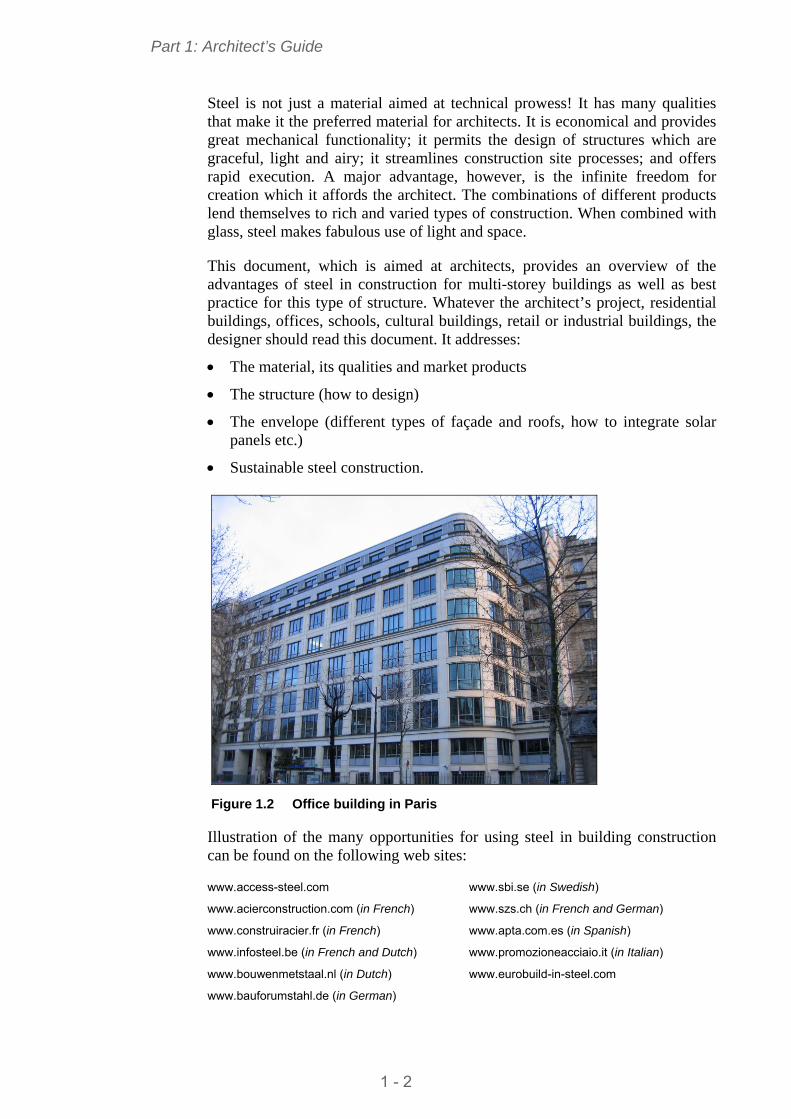
Figure 1.2 Office building in Paris
Illustration of the many opportunities for using steel in building construction can be found on the following web sites:
www.access-steel.com
www.acierconstruction.com (in French)
www.construiracier.fr (in French)
www.infosteel.be (in French and Dutch)
www.bouwenmetstaal.nl (in Dutch)
www.bauforumstahl.de (in German)
www.sbi.se (in Swedish)
www.szs.ch (in French and German)
www.apta.com.es (in Spanish)
www.promozioneacciaio.it (in Italian)
www.eurobuild-in-steel.com
1 - 2
Part 1: Architect’s Guide
2 FUNCTIONAL QUALITIES
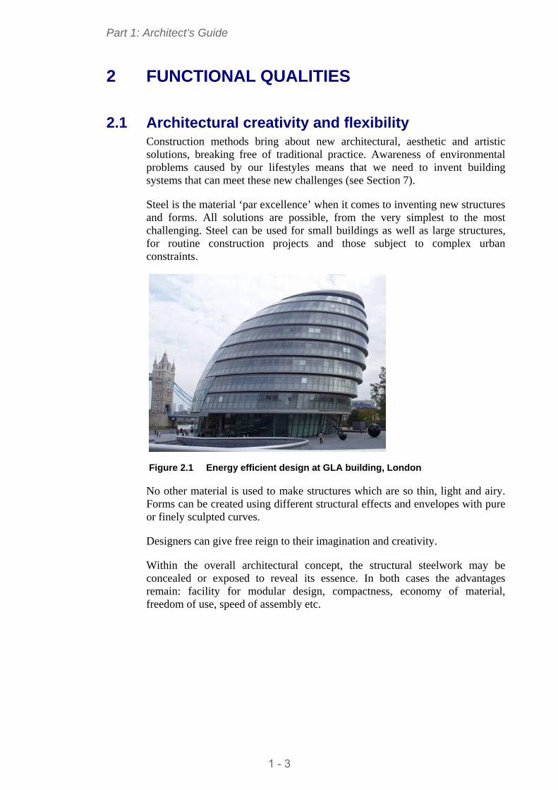
2.1 Architectural creativity and flexibility Construction methods bring about new architectural, aesthetic and artistic solutions, breaking free of traditional practice. Awareness of environmental problems caused by our lifestyles means that we need to invent building systems that can meet these new challenges (see Section 7).
Steel is the material ‘par excellence’ when it comes to inventing new structures and forms. All solutions are possible, from the very simplest to the most challenging. Steel can be used for small buildings as well as large structures, for routine construction projects and those subject to complex urban constraints.
Figure 2.1 Energy efficient design at GLA building, London
No other material is used to make structures which are so thin, light and airy. Forms can be created using different structural effects and envelopes with pure or finely sculpted curves.
Designers can give free reign to their imagination and creativity.
Within the overall architectural concept, the structural steelwork may be concealed or exposed to reveal its essence. In both cases the advantages remain: facility for modular design, compactness, economy of material, freedom of use, speed of assembly etc.
1 - 3
Part 1: Architect’s Guide
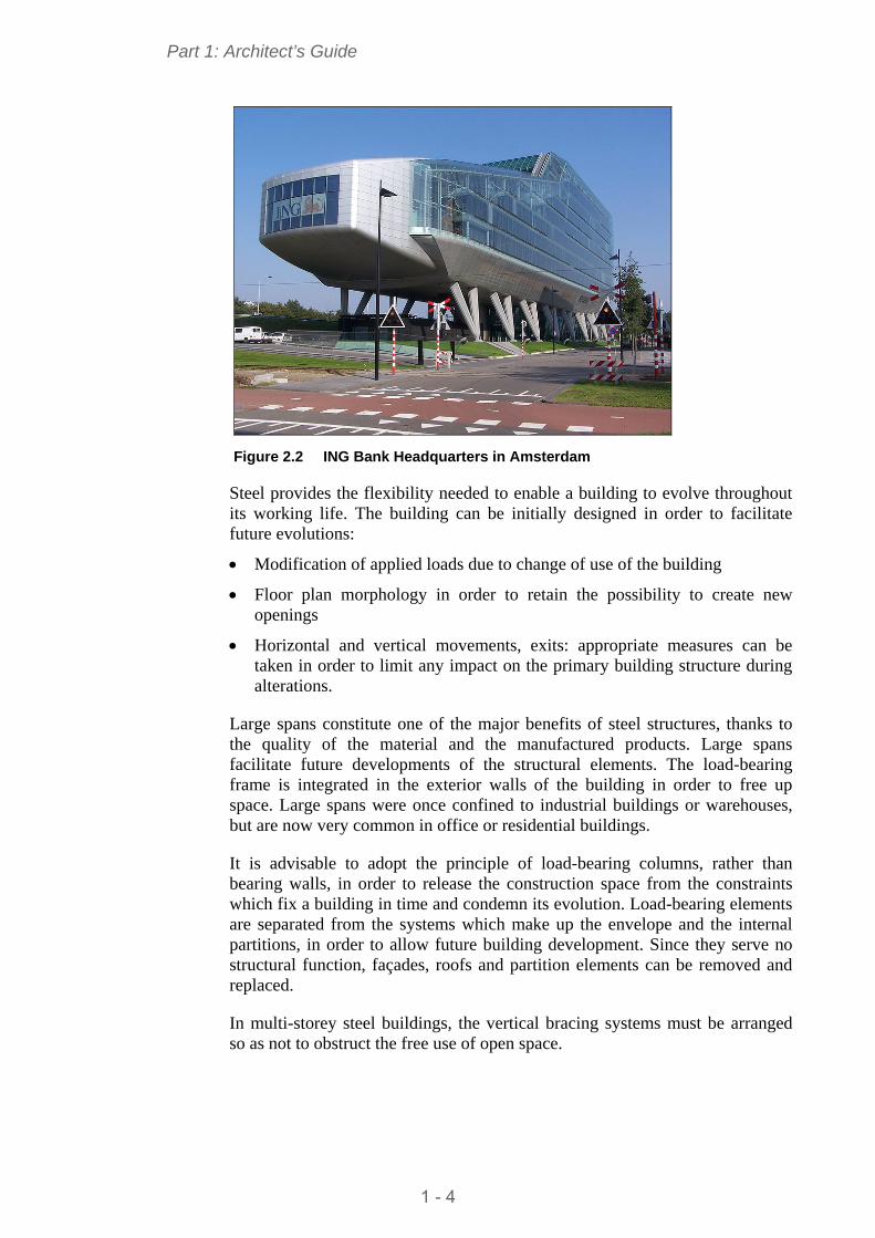
Figure 2.2 ING Bank Headquarters in Amsterdam
Steel provides the flexibility needed to enable a building to evolve throughout its working life. The building can be initially designed in order to facilitate future evolutions:
Modification of applied loads due to change of use of the building
Floor plan morphology in order to retain the possibility to create new openings
Horizontal and vertical movements, exits: appropriate measures can be taken in order to limit any impact on the primary building structure during alterations.
Large spans constitute one of the major benefits of steel structures, thanks to the quality of the material and the manufactured products. Large spans facilitate future developments of the structural elements. The load-bearing frame is integrated in the exterior walls of the building in order to free up space. Large spans were once confined to industrial buildings or warehouses, but are now very common in office or residential buildings.
It is advisable to adopt the principle of load-bearing columns, rather than bearing walls, in order to release the construction space from the constraints which fix a building in time and condemn its evolution. Load-bearing elements are separated from the systems which make up the envelope and the internal partitions, in order to allow future building development. Since they serve no structural function, façades, roofs and partition elements can be removed and replaced.
In multi-storey steel buildings, the vertical bracing systems must be arranged so as not to obstruct the free use of open space.
1 - 4
Part 1: Architect’s Guide
In order to design in steel, it is essential to understand the different aspects in the construction process:
Floors
Façades
Partitions
Roofing.
Each aspect involves various products assembled in a specific order (see relevant Sections).
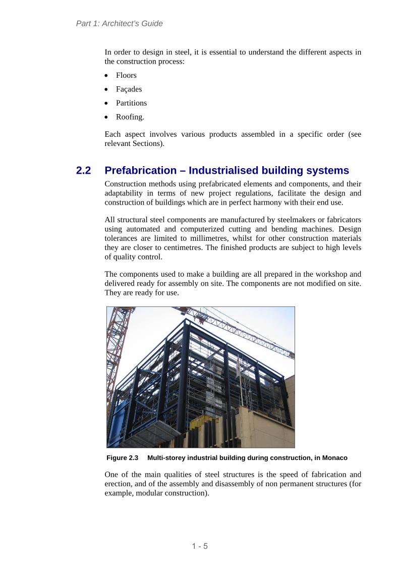
2.2 Prefabrication – Industrialised building systems Construction methods using prefabricated elements and components, and their adaptability in terms of new project regulations, facilitate the design and construction of buildings which are in perfect harmony with their end use.
All structural steel components are manufactured by steelmakers or fabricators using automated and computerized cutting and bending machines. Design tolerances are limited to millimetres, whilst for other construction materials they are closer to centimetres. The finished products are subject to high levels of quality control.
The components used to make a building are all prepared in the workshop and delivered ready for assembly on site. The components are not modified on site. They are ready for use.
Figure 2.3 Multi-storey industrial building during construction, in Monaco
One of the main qualities of steel structures is the speed of fabrication and erection, and of the assembly and disassembly of non permanent structures (for example, modular construction).
1 - 5
Part 1: Architect’s Guide
Intelligent use of steel products and components produced by manufacturers who are constantly innovating and developing, contributes to the transformation of our urban landscapes.
2.3 An evolving art Today’s perception of steel has evolved. Its qualities and advantages have been revealed, tried and tested. Moreover, the very wide range of accompanying products means the steel frame can respond to rapidly changing lifestyles and use.
Many buildings constructed after the Second World War no longer fulfil today’s needs, although they can be restructured and extended if the patrimonial value of the existing building is worth prolonging.
Steel buildings are designed with walls made of light composite products. This construction solution combines all of steel’s qualities.
2.4 Extending and refurbishment 2.4.1 Extending upwards
The concept of extending buildings upwards is very interesting. The designer can benefit from the foundation of existing buildings and their vertical connections.
Load-bearing steel frames are lightweight and adaptable for many situations. They provide an effective solution for the extension of old buildings, whatever the original material, and help find the right balance between the weight of the new structure and the admissible loads.
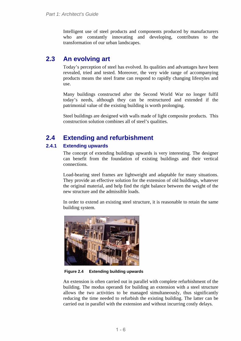
In order to extend an existing steel structure, it is reasonable to retain the same building system.
Figure 2.4 Extending building upwards
An extension is often carried out in parallel with complete refurbishment of the building. The modus operandi for building an extension with a steel structure allows the two activities to be managed simultaneously, thus significantly reducing the time needed to refurbish the existing building. The latter can be carried out in parallel with the extension and without incurring costly delays.
1 - 6
Part 1: Architect’s Guide
Depending on the load-bearing structure of the extension, and in the case of a reinforced concrete building whose width is not altered, the steel frame may, for the most part, be installed on the external concrete walls or columns, or even fixed to the external walls of the façades on each floor, in order to distribute the load. Both solutions avoid having to create a new structure across different levels or new foundations that are costly and difficult to build.
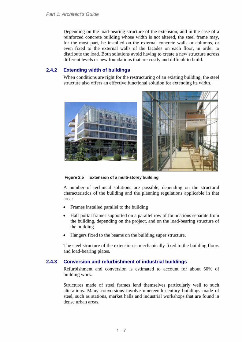
2.4.2 Extending width of buildings
When conditions are right for the restructuring of an existing building, the steel structure also offers an effective functional solution for extending its width.
Figure 2.5 Extension of a multi-storey building
A number of technical solutions are possible, depending on the structural characteristics of the building and the planning regulations applicable in that area:
Frames installed parallel to the building
Half portal frames supported on a parallel row of foundations separate from the building, depending on the project, and on the load-bearing structure of the building
Hangers fixed to the beams on the building super structure.
The steel structure of the extension is mechanically fixed to the building floors and load-bearing plates.
2.4.3 Conversion and refurbishment of industrial buildings
Refurbishment and conversion is estimated to account for about 50% of building work.
Structures made of steel frames lend themselves particularly well to such alterations. Many conversions involve nineteenth century buildings made of steel, such as stations, market halls and industrial workshops that are found in dense urban areas.
1 - 7
Part 1: Architect’s Guide
It is easy to remove components, to replace and modify spans, to change beam or column dimensions. The ability to suspend building floors from roof structures offers additional flexibility for new projects associated with existing buildings.
It is also worth noting that the lightness of steel structures is a distinct advantage when adding new floors by means of connections to existing structures (once their potential has been verified). If new foundations are required for the installation of new structures, these can be designed easily and in such a way that they do not interfere with existing foundations.
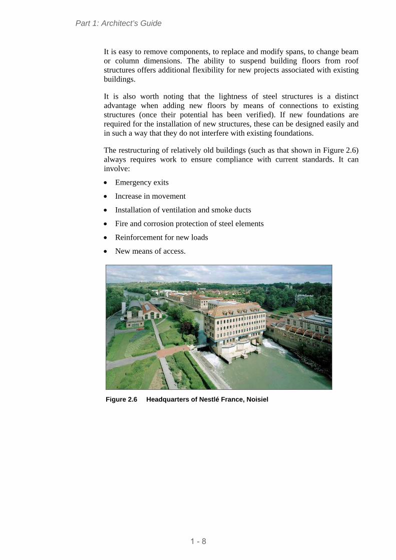
The restructuring of relatively old buildings (such as that shown in Figure 2.6) always requires work to ensure compliance with current standards. It can involve:
Emergency exits
Increase in movement
Installation of ventilation and smoke ducts
Fire and corrosion protection of steel elements
Reinforcement for new loads
New means of access.
Figure 2.6 Headquarters of Nestlé France, Noisiel
1 - 8
Part 1: Architect’s Guide
3 STEEL – MATERIAL AND PRODUCTS
3.1 Steel the material Steel offers exceptional qualities in terms of mechanical resistance. Of the most commonly used materials in construction, it demonstrates the greatest resistance for the lightest section, both in tension and compression. This opens the door for architects to a wide choice of technical and aesthetic solutions.
There are many types of steel. These are classified, according to their composition. There are three main categories of steel:
Non-alloy steel grades
Stainless steel grades
Other alloy steel grades.
Non-alloy steel grades are commonly used in the construction sector. The main steel grades are S235, S275 and S355 for structural members. However the higher strength steel S460 grade is used more and more in construction.
Steel products must demonstrate specific characteristics according to their grade and form and as defined by National or European standards.
Full information can be found on steel producers’ web sites:
www.arcelormittal.com/sections
www.corusconstruction.com
www.peiner-traeger.de
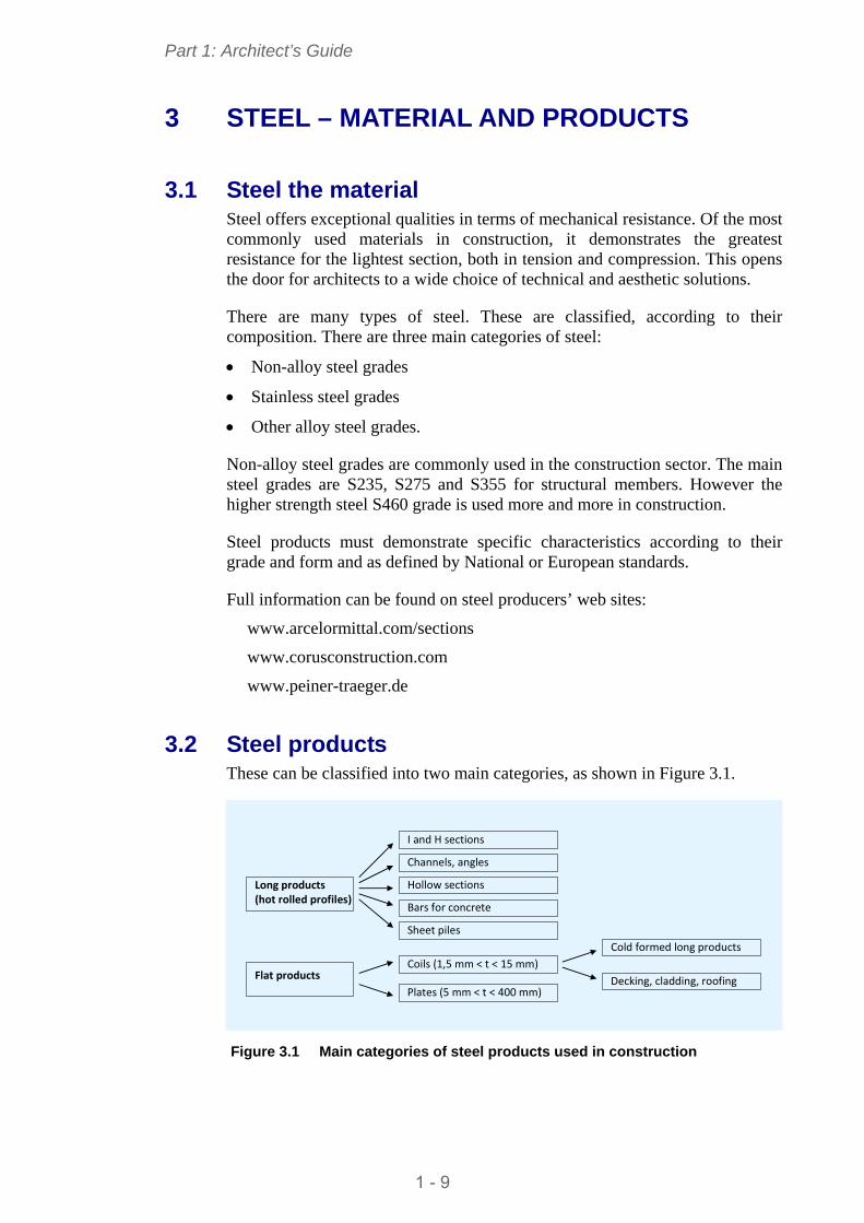
3.2 Steel products These can be classified into two main categories, as shown in Figure 3.1.
I and H sections
Channels, angles
Bars for concrete
Sheet piles
Long products (hot rolled profiles)
Coils (1,5 mm < t < 15 mm)
Plates (5 mm < t < 400 mm)
Flat products
Hollow sections
Cold formed long products
Decking, cladding, roofing
Figure 3.1 Main categories of steel products used in construction
1 - 9
Part 1: Architect’s Guide
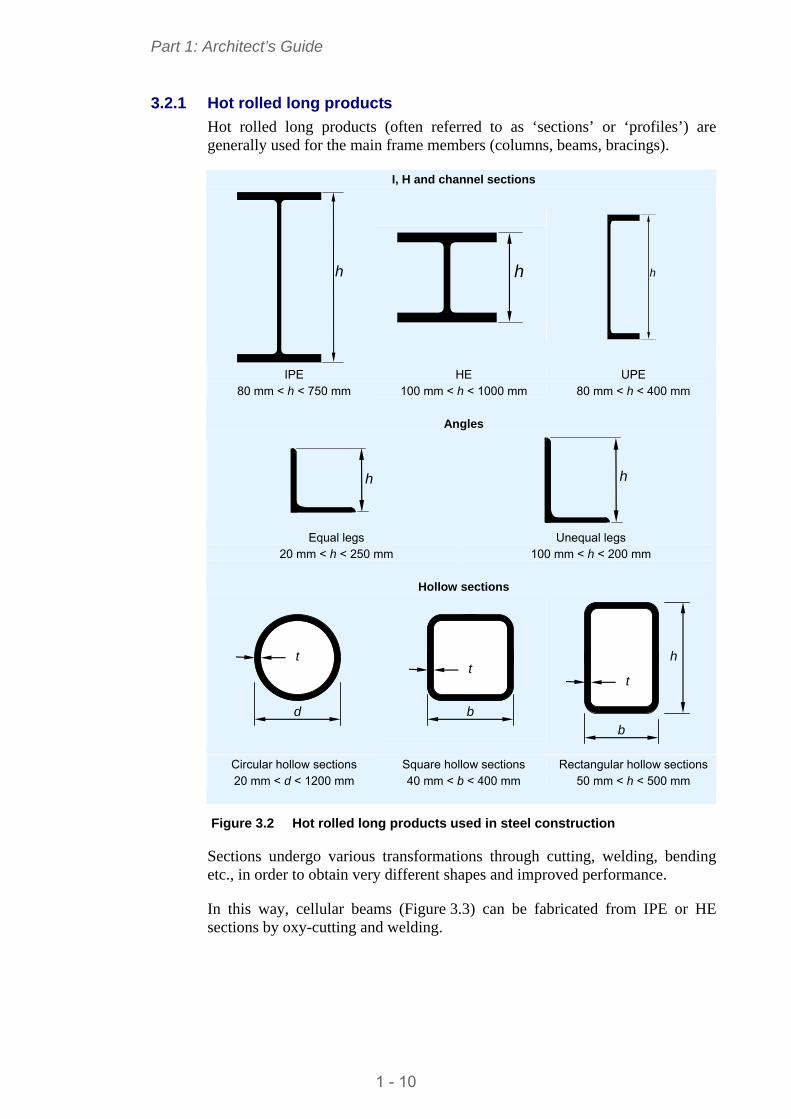
3.2.1 Hot rolled long products
Hot rolled long products (often referred to as ‘sections’ or ‘profiles’) are generally used for the main frame members (columns, beams, bracings).
I, H and channel sections
h
h
h
IPE 80 mm < h < 750 mm
HE 100 mm < h < 1000 mm
UPE 80 mm < h < 400 mm
Angles
h
h
Equal legs
20 mm < h < 250 mm
Unequal legs 100 mm < h < 200 mm
Hollow sections
d
t
b
t
b
t
h
Circular hollow sections 20 mm < d < 1200 mm
Square hollow sections 40 mm < b < 400 mm
Rectangular hollow sections 50 mm < h < 500 mm
Figure 3.2 Hot rolled long products used in steel construction
Sections undergo various transformations through cutting, welding, bending etc., in order to obtain very different shapes and improved performance.
In this way, cellular beams (Figure 3.3) can be fabricated from IPE or HE sections by oxy-cutting and welding.
1 - 10
Part 1: Architect’s Guide
Figure 3.3 Cellular beams fabricated from hot rolled sections
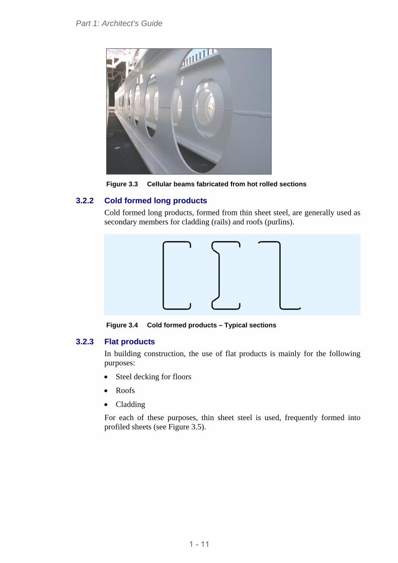
3.2.2 Cold formed long products
Cold formed long products, formed from thin sheet steel, are generally used as secondary members for cladding (rails) and roofs (purlins).
Figure 3.4 Cold formed products – Typical sections
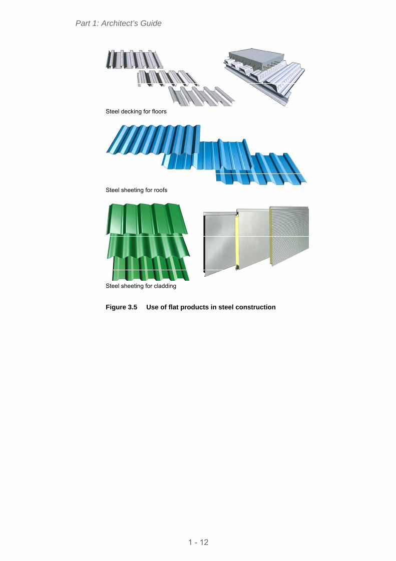
3.2.3 Flat products
In building construction, the use of flat products is mainly for the following purposes:
Steel decking for floors
Roofs
Cladding
For each of these purposes, thin sheet steel is used, frequently formed into profiled sheets (see Figure 3.5).
1 - 11
Part 1: Architect’s Guide
Steel decking for floors
Steel sheeting for roofs
Steel sheeting for cladding
Figure 3.5 Use of flat products in steel construction
1 - 12
Part 1: Architect’s Guide
4 BASIS OF GOOD DESIGN: THE STRUCTURE
4.1 The load-bearing system In multi-storey structures, load-bearing and load distribution functions are ensured by installing a main frame consisting of beams and columns.
4.1.1 Load-bearing framework
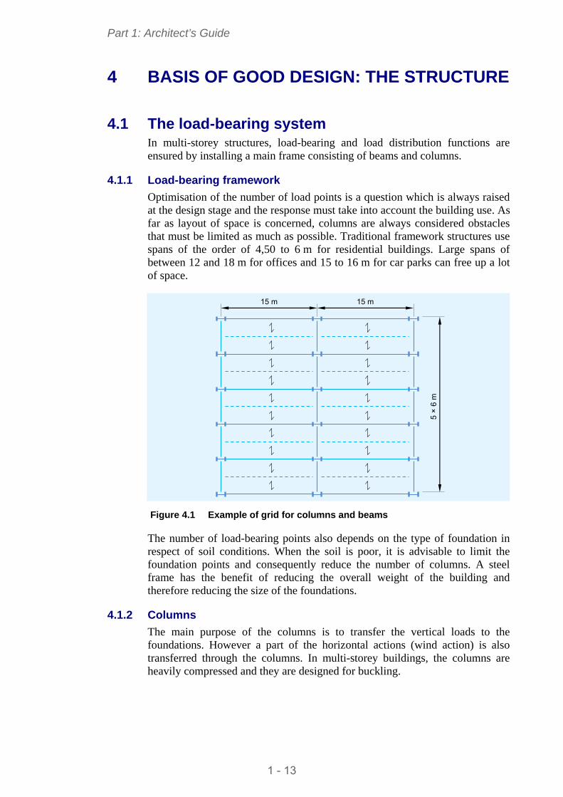
Optimisation of the number of load points is a question which is always raised at the design stage and the response must take into account the building use. As far as layout of space is concerned, columns are always considered obstacles that must be limited as much as possible. Traditional framework structures use spans of the order of 4,50 to 6 m for residential buildings. Large spans of between 12 and 18 m for offices and 15 to 16 m for car parks can free up a lot of space.
15 m 15 m
5 ×
6 m
Figure 4.1 Example of grid for columns and beams
The number of load-bearing points also depends on the type of foundation in respect of soil conditions. When the soil is poor, it is advisable to limit the foundation points and consequently reduce the number of columns. A steel frame has the benefit of reducing the overall weight of the building and therefore reducing the size of the foundations.
4.1.2 Columns
The main purpose of the columns is to transfer the vertical loads to the foundations. However a part of the horizontal actions (wind action) is also transferred through the columns. In multi-storey buildings, the columns are heavily compressed and they are designed for buckling.
1 - 13
Part 1: Architect’s Guide
The criteria which help to determine the choice of column are usually the following:
Architectural preference
Grid layout and size
Cost of steel products (I or H sections are less expensive than hollow sections)
Installation costs (complexity of installation)
Ease and simplicity with which secondary components (for façades, walls, ceilings) can be connected
Work and products needed to respond to essential requirements (fire, corrosion, etc.).
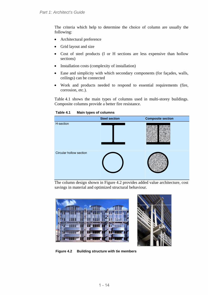
Table 4.1 shows the main types of columns used in multi-storey buildings. Composite columns provide a better fire resistance.
Table 4.1 Main types of columns
Steel section Composite section
H-section
Circular hollow section
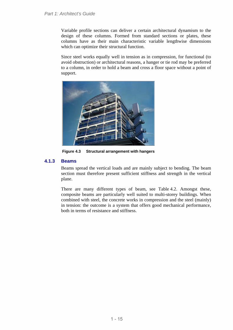
The column design shown in Figure 4.2 provides added value architecture, cost savings in material and optimized structural behaviour.
Figure 4.2 Building structure with tie members
1 - 14
Part 1: Architect’s Guide
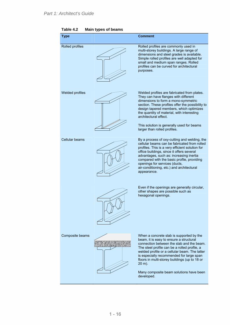
Variable profile sections can deliver a certain architectural dynamism to the design of these columns. Formed from standard sections or plates, these columns have as their main characteristic variable lengthwise dimensions which can optimize their structural function.
Since steel works equally well in tension as in compression, for functional (to avoid obstruction) or architectural reasons, a hanger or tie rod may be preferred to a column, in order to hold a beam and cross a floor space without a point of support.
Figure 4.3 Structural arrangement with hangers
4.1.3 Beams
Beams spread the vertical loads and are mainly subject to bending. The beam section must therefore present sufficient stiffness and strength in the vertical plane.
There are many different types of beam, see Table 4.2. Amongst these, composite beams are particularly well suited to multi-storey buildings. When combined with steel, the concrete works in compression and the steel (mainly) in tension: the outcome is a system that offers good mechanical performance, both in terms of resistance and stiffness.
1 - 15
Part 1: Architect’s Guide
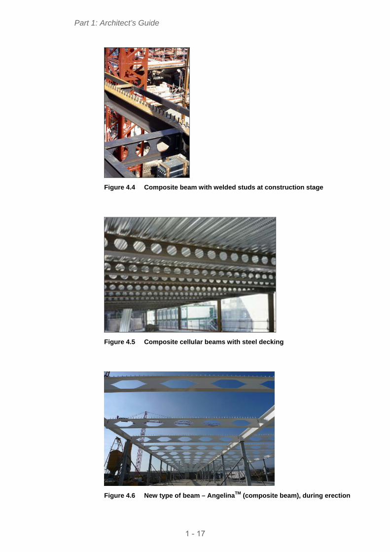
Table 4.2 Main types of beams
Type Comment
Rolled profiles Rolled profiles are commonly used in multi-storey buildings. A large range of dimensions and steel grades is available. Simple rolled profiles are well adapted for small and medium span ranges. Rolled profiles can be curved for architectural purposes.
Welded profiles Welded profiles are fabricated from plates. They can have flanges with different dimensions to form a mono-symmetric section. These profiles offer the possibility to design tapered members, which optimizes the quantity of material, with interesting architectural effect.
This solution is generally used for beams larger than rolled profiles.
Cellular beams By a process of oxy-cutting and welding, the cellular beams can be fabricated from rolled profiles. This is a very efficient solution for office buildings, since it offers several advantages, such as: increasing inertia compared with the basic profile, providing openings for services (ducts, air-conditioning, etc.) and architectural appearance.
Even if the openings are generally circular, other shapes are possible such as hexagonal openings.
Composite beams
When a concrete slab is supported by the beam, it is easy to ensure a structural connection between the slab and the beam. The steel profile can be a rolled profile, a welded profile or a cellular beam. The latter is especially recommended for large span floors in multi-storey buildings (up to 18 or 20 m).
Many composite beam solutions have been developed.
1 - 16
Part 1: Architect’s Guide
Figure 4.4 Composite beam with welded studs at construction stage
Figure 4.5 Composite cellular beams with steel decking
Figure 4.6 New type of beam – AngelinaTM (composite beam), during erection
1 - 17
Part 1: Architect’s Guide
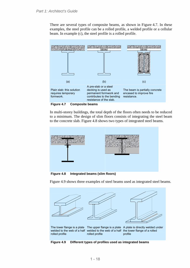
There are several types of composite beams, as shown in Figure 4.7. In these examples, the steel profile can be a rolled profile, a welded profile or a cellular beam. In example (c), the steel profile is a rolled profile.
(a)
(b)
(c)
Plain slab: this solution requires temporary formwork.
A pre-slab or a steel decking is used as permanent formwork and contributes to the bending resistance of the slab.
The beam is partially concrete encased to improve fire resistance.
Figure 4.7 Composite beams
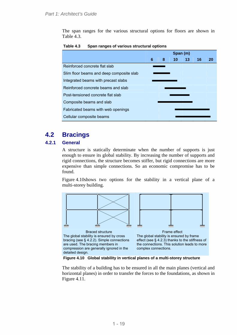
In multi-storey buildings, the total depth of the floors often needs to be reduced to a minimum. The design of slim floors consists of integrating the steel beam to the concrete slab. Figure 4.8 shows two types of integrated steel beams.
Figure 4.8 Integrated beams (slim floors)
Figure 4.9 shows three examples of steel beams used as integrated steel beams.
The lower flange is a plate welded to the web of a half rolled profile
The upper flange is a plate welded to the web of a half rolled profile
A plate is directly welded under the lower flange of a rolled profile
Figure 4.9 Different types of profiles used as integrated beams
1 - 18
Part 1: Architect’s Guide
The span ranges for the various structural options for floors are shown in Table 4.3.
Table 4.3 Span ranges of various structural options
Span (m)
8 6 10 13 16 20
Reinforced concrete flat slab
Slim floor beams and deep composite slab
Integrated beams with precast slabs
Reinforced concrete beams and slab
Post-tensioned concrete flat slab
Composite beams and slab
Fabricated beams with web openings
Cellular composite beams
4.2 Bracings 4.2.1 General
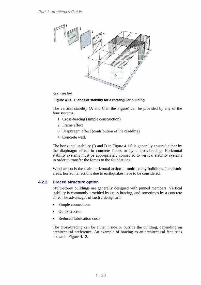
A structure is statically determinate when the number of supports is just enough to ensure its global stability. By increasing the number of supports and rigid connections, the structure becomes stiffer, but rigid connections are more expensive than simple connections. So an economic compromise has to be found.
Figure 4.10shows two options for the stability in a vertical plane of a multi-storey building.
Braced structure
The global stability is ensured by cross bracing (see § 4.2.2). Simple connections are used. The bracing members in compression are generally ignored in the detailed design.
Frame effect The global stability is ensured by frame effect (see § 4.2.3) thanks to the stiffness of the connections. This solution leads to more complex connections.
Figure 4.10 Global stability in vertical planes of a multi-storey structure
The stability of a building has to be ensured in all the main planes (vertical and horizontal planes) in order to transfer the forces to the foundations, as shown in Figure 4.11.
1 - 19
Part 1: Architect’s Guide
1 2
3 4
Key: - see text Figure 4.11 Planes of stability for a rectangular building
The vertical stability (A and C in the Figure) can be provided by any of the four systems:
1 Cross-bracing (simple construction)
2 Frame effect
3 Diaphragm effect (contribution of the cladding)
4 Concrete wall.
The horizontal stability (B and D in Figure 4.11) is generally ensured either by the diaphragm effect in concrete floors or by a cross-bracing. Horizontal stability systems must be appropriately connected to vertical stability systems in order to transfer the forces to the foundations.
Wind action is the main horizontal action in multi-storey buildings. In seismic areas, horizontal actions due to earthquakes have to be considered.
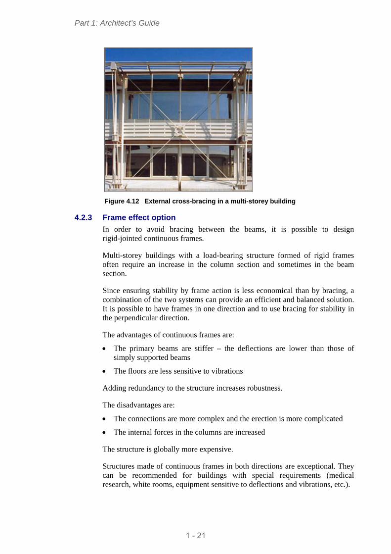
4.2.2 Braced structure option
Multi-storey buildings are generally designed with pinned members. Vertical stability is commonly provided by cross-bracing, and sometimes by a concrete core. The advantages of such a design are:
Simple connections
Quick erection
Reduced fabrication costs.
The cross-bracing can be either inside or outside the building, depending on architectural preference. An example of bracing as an architectural feature is shown in Figure 4.12.
1 - 20
Part 1: Architect’s Guide
Figure 4.12 External cross-bracing in a multi-storey building
4.2.3 Frame effect option
In order to avoid bracing between the beams, it is possible to design rigid-jointed continuous frames.
Multi-storey buildings with a load-bearing structure formed of rigid frames often require an increase in the column section and sometimes in the beam section.
Since ensuring stability by frame action is less economical than by bracing, a combination of the two systems can provide an efficient and balanced solution. It is possible to have frames in one direction and to use bracing for stability in the perpendicular direction.
The advantages of continuous frames are:
The primary beams are stiffer – the deflections are lower than those of simply supported beams
The floors are less sensitive to vibrations
Adding redundancy to the structure increases robustness.
The disadvantages are:
The connections are more complex and the erection is more complicated
The internal forces in the columns are increased
The structure is globally more expensive.
Structures made of continuous frames in both directions are exceptional. They can be recommended for buildings with special requirements (medical research, white rooms, equipment sensitive to deflections and vibrations, etc.).
1 - 21
Part 1: Architect’s Guide
4.3 Floors 4.3.1 General
The structural function of floors is to transfer loads to the main members of the structure. Floors also contribute to the global stability of the structure because they generally act as a diaphragm to provide stability in the horizontal plane of each storey.
The design of a floor conforms to specifications that include:
Applied loads
Thermal performance
Acoustic performance
Fire resistance
Service integration
Requirements to connect a false ceiling.
The structural part of the floor can be one of the following:
Composite slab using steel decking
Concrete slab with steel decking used as permanent formwork
Dry floors
Plain slab, concrete slab including a precast slab
Prefabricated slab.
4.3.2 Concrete slab with steel decking
The use of steel decking has many advantages:
Efficient permanent formwork (the formwork does not have to be removed after concreting)
Installation of a steel decking is easier than that of a precast slab
Propping during construction is often not necessary.
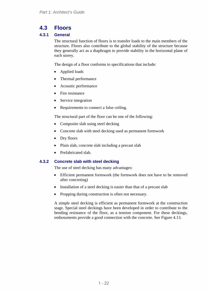
A simple steel decking is efficient as permanent formwork at the construction stage. Special steel deckings have been developed in order to contribute to the bending resistance of the floor, as a tension component. For these deckings, embossments provide a good connection with the concrete. See Figure 4.13.
1 - 22
Part 1: Architect’s Guide
Permanent formwork (Non composite slab)
Composite slabs
(Steel deckings with embossments) Figure 4.13 Concrete slab with steel decking
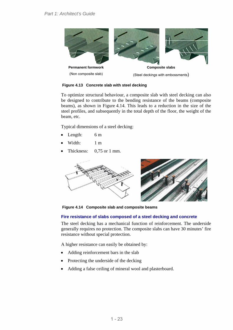
To optimize structural behaviour, a composite slab with steel decking can also be designed to contribute to the bending resistance of the beams (composite beams), as shown in Figure 4.14. This leads to a reduction in the size of the steel profiles, and subsequently in the total depth of the floor, the weight of the beam, etc.
Typical dimensions of a steel decking:
Length: 6 m
Width: 1 m
Thickness: 0,75 or 1 mm.
Figure 4.14 Composite slab and composite beams
Fire resistance of slabs composed of a steel decking and concrete
The steel decking has a mechanical function of reinforcement. The underside generally requires no protection. The composite slabs can have 30 minutes’ fire resistance without special protection.
A higher resistance can easily be obtained by:
Adding reinforcement bars in the slab
Protecting the underside of the decking
Adding a false ceiling of mineral wool and plasterboard.
1 - 23
Part 1: Architect’s Guide
4.3.3 Precast slab with in-situ topping
Plain slabs are generally composed of a precast slab and cast-in-situ concrete. At the concreting stage, temporary supports may be needed to transfer the weight of the precast slab, the concrete and operatives working on the site.
The slab can contribute to the bending resistance and stiffness of the beams if an appropriate connection (welded studs for instance) is provided between the slab and the beam – see composite beams in Table 4.3.
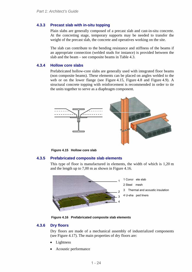
4.3.4 Hollow core slabs
Prefabricated hollow-core slabs are generally used with integrated floor beams (non composite beams). These elements can be placed on angles welded to the web or on the lower flange (see Figure 4.15, Figure 4.8 and Figure 4.9). A structural concrete topping with reinforcement is recommended in order to tie the units together to serve as a diaphragm component.
Figure 4.15 Hollow core slab
4.3.5 Prefabricated composite slab elements
This type of floor is manufactured in elements, the width of which is 1,20 m and the length up to 7,00 m as shown in Figure 4.16.
1
2
3
4
1 Concr ete slab
2 Steel mesh
3 Thermal and acoustic insulation
4 U-sha ped liners
Figure 4.16 Prefabricated composite slab elements
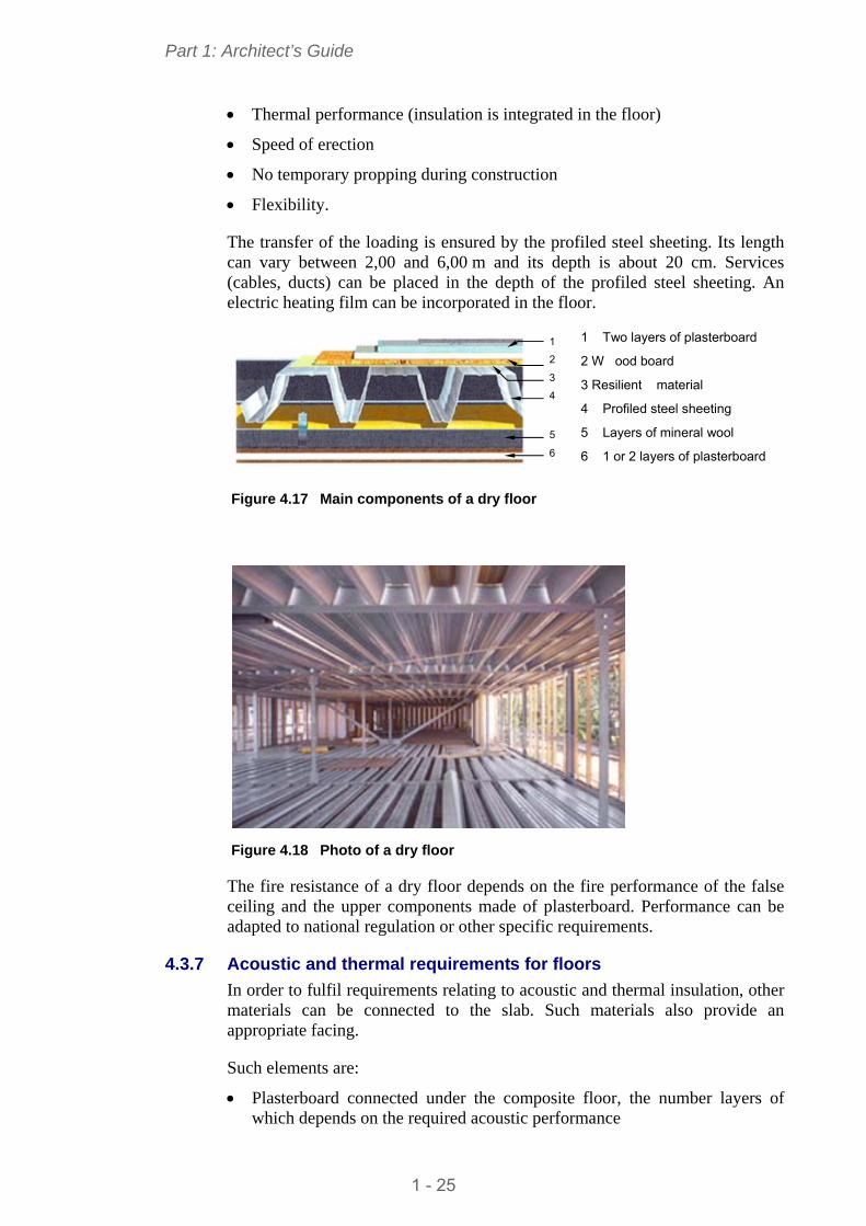
4.3.6 Dry floors
Dry floors are made of a mechanical assembly of industrialized components (see Figure 4.17). The main properties of dry floors are:
Lightness
Acoustic performance
1 - 24
Part 1: Architect’s Guide
Thermal performance (insulation is integrated in the floor)
Speed of erection
No temporary propping during construction
Flexibility.
The transfer of the loading is ensured by the profiled steel sheeting. Its length can vary between 2,00 and 6,00 m and its depth is about 20 cm. Services (cables, ducts) can be placed in the depth of the profiled steel sheeting. An electric heating film can be incorporated in the floor.
1 Two layers of plasterboard
1
2
3
4
5
6
2 W ood board
3 Resilient material
4 Profiled steel sheeting
5 Layers of mineral wool
6 1 or 2 layers of plasterboard
Figure 4.17 Main components of a dry floor
Figure 4.18 Photo of a dry floor
The fire resistance of a dry floor depends on the fire performance of the false ceiling and the upper components made of plasterboard. Performance can be adapted to national regulation or other specific requirements.
4.3.7 Acoustic and thermal requirements for floors
In order to fulfil requirements relating to acoustic and thermal insulation, other materials can be connected to the slab. Such materials also provide an appropriate facing.
Such elements are:
Plasterboard connected under the composite floor, the number layers of which depends on the required acoustic performance
1 - 25
Part 1: Architect’s Guide
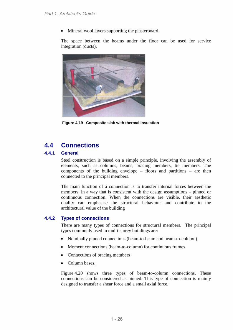
Mineral wool layers supporting the plasterboard.
The space between the beams under the floor can be used for service integration (ducts).
Figure 4.19 Composite slab with thermal insulation
4.4 Connections 4.4.1 General
Steel construction is based on a simple principle, involving the assembly of elements, such as columns, beams, bracing members, tie members. The components of the building envelope – floors and partitions – are then connected to the principal members.
The main function of a connection is to transfer internal forces between the members, in a way that is consistent with the design assumptions – pinned or continuous connection. When the connections are visible, their aesthetic quality can emphasise the structural behaviour and contribute to the architectural value of the building
4.4.2 Types of connections
There are many types of connections for structural members. The principal types commonly used in multi-storey buildings are:
Nominally pinned connections (beam-to-beam and beam-to-column)
Moment connections (beam-to-column) for continuous frames
Connections of bracing members
Column bases.
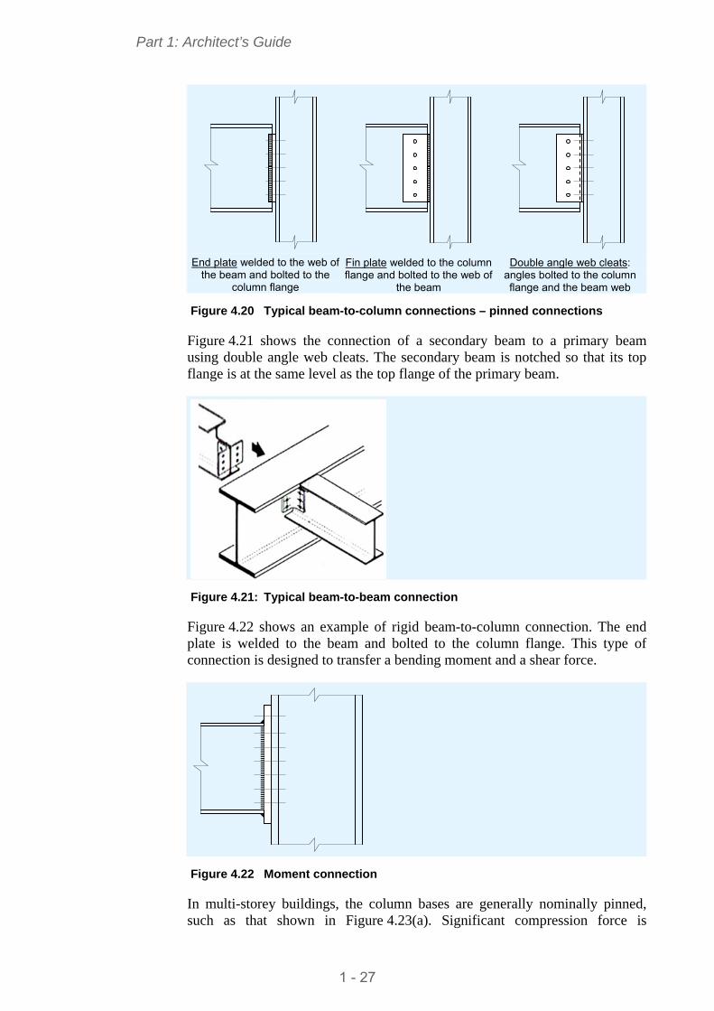
Figure 4.20 shows three types of beam-to-column connections. These connections can be considered as pinned. This type of connection is mainly designed to transfer a shear force and a small axial force.
1 - 26
Part 1: Architect’s Guide
End plate welded to the web of
the beam and bolted to the column flange
Fin plate welded to the column flange and bolted to the web of
the beam
Double angle web cleats:
angles bolted to the column flange and the beam web
Figure 4.20 Typical beam-to-column connections – pinned connections
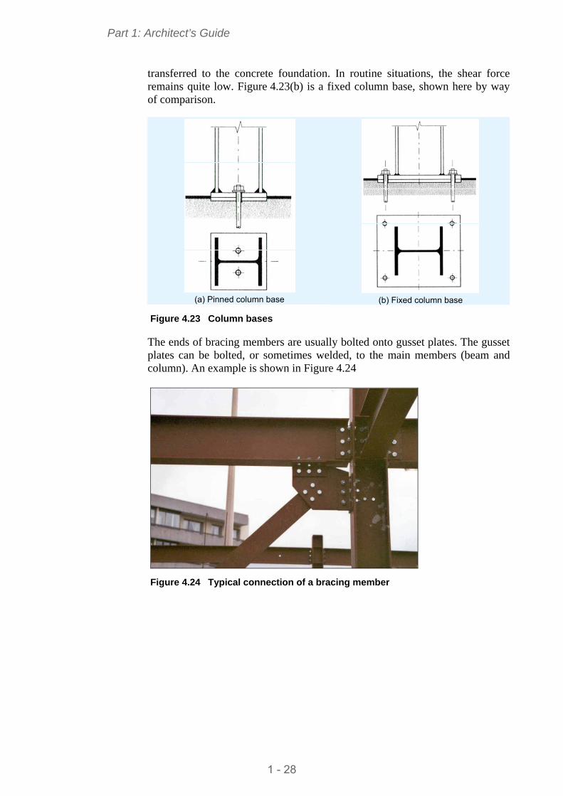
Figure 4.21 shows the connection of a secondary beam to a primary beam using double angle web cleats. The secondary beam is notched so that its top flange is at the same level as the top flange of the primary beam.
Figure 4.21: Typical beam-to-beam connection
Figure 4.22 shows an example of rigid beam-to-column connection. The end plate is welded to the beam and bolted to the column flange. This type of connection is designed to transfer a bending moment and a shear force.
Figure 4.22 Moment connection
In multi-storey buildings, the column bases are generally nominally pinned, such as that shown in Figure 4.23(a). Significant compression force is
1 - 27
Part 1: Architect’s Guide
transferred to the concrete foundation. In routine situations, the shear force remains quite low. Figure 4.23(b) is a fixed column base, shown here by way of comparison.
(a) Pinned column base
(b) Fixed column base
Figure 4.23 Column bases
The ends of bracing members are usually bolted onto gusset plates. The gusset plates can be bolted, or sometimes welded, to the main members (beam and column). An example is shown in Figure 4.24
Figure 4.24 Typical connection of a bracing member
1 - 28
Part 1: Architect’s Guide
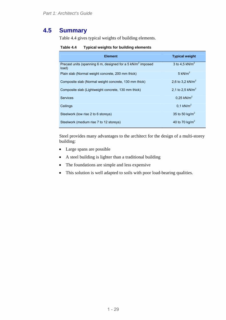
4.5 Summary Table 4.4 gives typical weights of building elements.
Table 4.4 Typical weights for building elements
Element Typical weight
Precast units (spanning 6 m, designed for a 5 kN/m2 imposed load)
3 to 4,5 kN/m2
5 kN/m2 Plain slab (Normal weight concrete, 200 mm thick)
2,6 to 3,2 kN/m2 Composite slab (Normal weight concrete, 130 mm thick)
2,1 to 2,5 kN/m2 Composite slab (Lightweight concrete, 130 mm thick)
0,25 kN/m2 Services
0,1 kN/m2 Ceilings
35 to 50 kg/m2 Steelwork (low rise 2 to 6 storeys)
40 to 70 kg/m2 Steelwork (medium rise 7 to 12 storeys)
Steel provides many advantages to the architect for the design of a multi-storey building:
Large spans are possible
A steel building is lighter than a traditional building
The foundations are simple and less expensive
This solution is well adapted to soils with poor load-bearing qualities.
1 - 29
Part 1: Architect’s Guide
5 BASIS OF GOOD DESIGN: THE ENVELOPE
5.1 Façades 5.1.1 General remarks
When steel is the material of choice for construction, façades are made up of a series of fabricated products which fulfil the following functions: load-bearing capacity, air tightness, water tightness, protection against intrusion, thermal and acoustic insulation, fire protection and, of course, aesthetic appearance.
Application of these products for façade systems guarantees a high level of precision and performance and therefore demands a certain degree of design rigour, particularly in the connection and cladding details of the various components.
With its component elements, the steel in a façade can be used for secondary frames (light steel elements or double skin façade with steel sheeting or trays), support for external facing, cladding and, lastly, for decoration and solar protection.
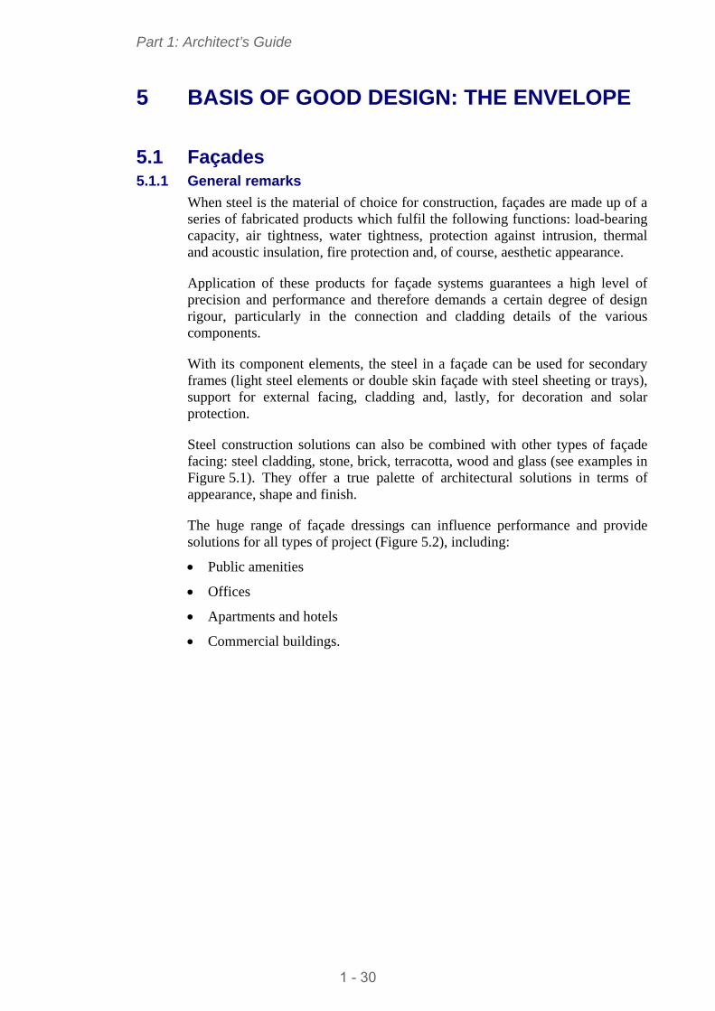
Steel construction solutions can also be combined with other types of façade facing: steel cladding, stone, brick, terracotta, wood and glass (see examples in Figure 5.1). They offer a true palette of architectural solutions in terms of appearance, shape and finish.
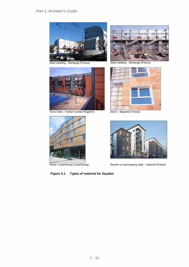
The huge range of façade dressings can influence performance and provide solutions for all types of project (Figure 5.2), including:
Public amenities
Offices
Apartments and hotels
Commercial buildings.
1 - 30
Part 1: Architect’s Guide
Steel cladding – Montargis (France)
Steel cladding – Montargis (France)
Terra Cotta – Fulham (United Kingdom)
Stone – Bagnolet (France)
Wood– Luxembourg (Luxembourg)
Render on load-bearing walls – Helsinki (Finland)
Figure 5.1 Types of material for façades
1 - 31
Part 1: Architect’s Guide
Millenaris – Budapest (Hungary)
European Parliament (France)
House buildings - Evreux (France)
University – Torino (Italy)
Figure 5.2 Façades for various types of project
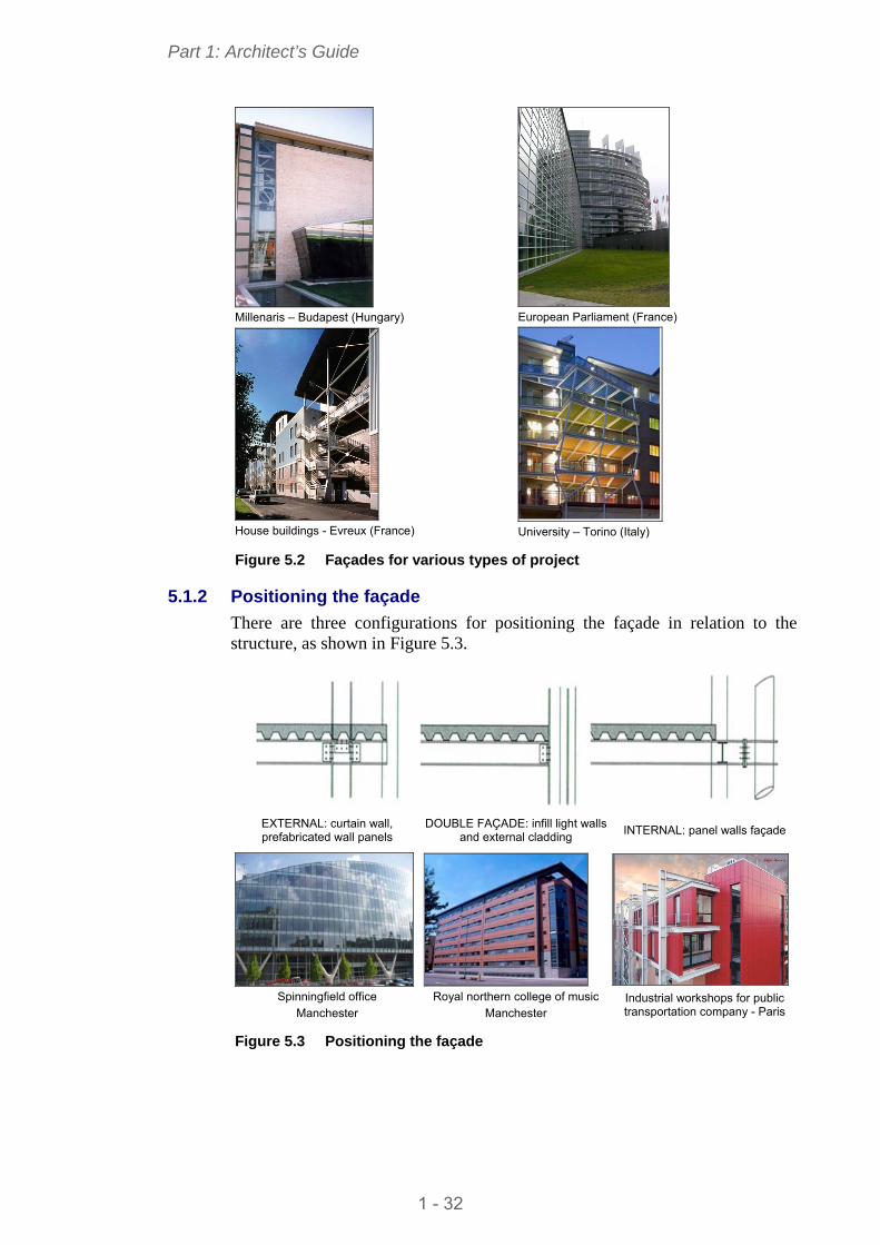
5.1.2 Positioning the façade
There are three configurations for positioning the façade in relation to the structure, as shown in Figure 5.3.
EXTERNAL: curtain wall, prefabricated wall panels
DOUBLE FAÇADE: infill light walls and external cladding INTERNAL: panel walls façade
Spinningfield office
Manchester Royal northern college of music
Manchester Industrial workshops for public transportation company - Paris
Figure 5.3 Positioning the façade
1 - 32
Part 1: Architect’s Guide
The features of these three options are:
A completely external façade: the structure is visible inside
- The façade is a series of panels installed between floors
- If the column is hidden, the most cost efficient section should be used
- If the column is visible, the aesthetic appearance will need to be considered.
- In this case, fire protection requirements vary according to the building use and there are numerous solutions to satisfy these (see 6.2.4).
A double façade thickness:
- Generally speaking, and since the column is not visible, the most economic solution will be determined by the choice of section.
- If sizing leads to a discontinuity in the façade facing, the columns can be divided into two in order to reduce obstruction.
- Internal and external facings which have been adapted will ensure structural fire protection.
Internal façade: the structure is visible outside the building
- The façade beam connection must be examined carefully, especially in terms of thermal, structural and fire protection needs. Special arrangements can be put in place.
5.1.3 The construction principle
In most construction elements for lightweight façades, the edge of the floor is used to determine the limit. The vertical plane it defines is for fixing elements, for reducing thermal bridging and for fire protection between floor levels.
On the outside, are the support elements for the external facing (secondary frames, plates), which are installed vertically or sometimes horizontally. A primary layer of thermal insulation is then applied. The external facing is placed on this frame using a fixing device (transverse frame, bracing, pre-frame, etc.). The external facing can be fabricated panels with insulation (Figure 5.4).
On the inside, a double-skinned partition, comprising between one and three layers of plasterboard fixed to a light steel frame, is commonly used. Additional insulation is applied between the frame posts (Figure 5.5).
1 - 33
Part 1: Architect’s Guide
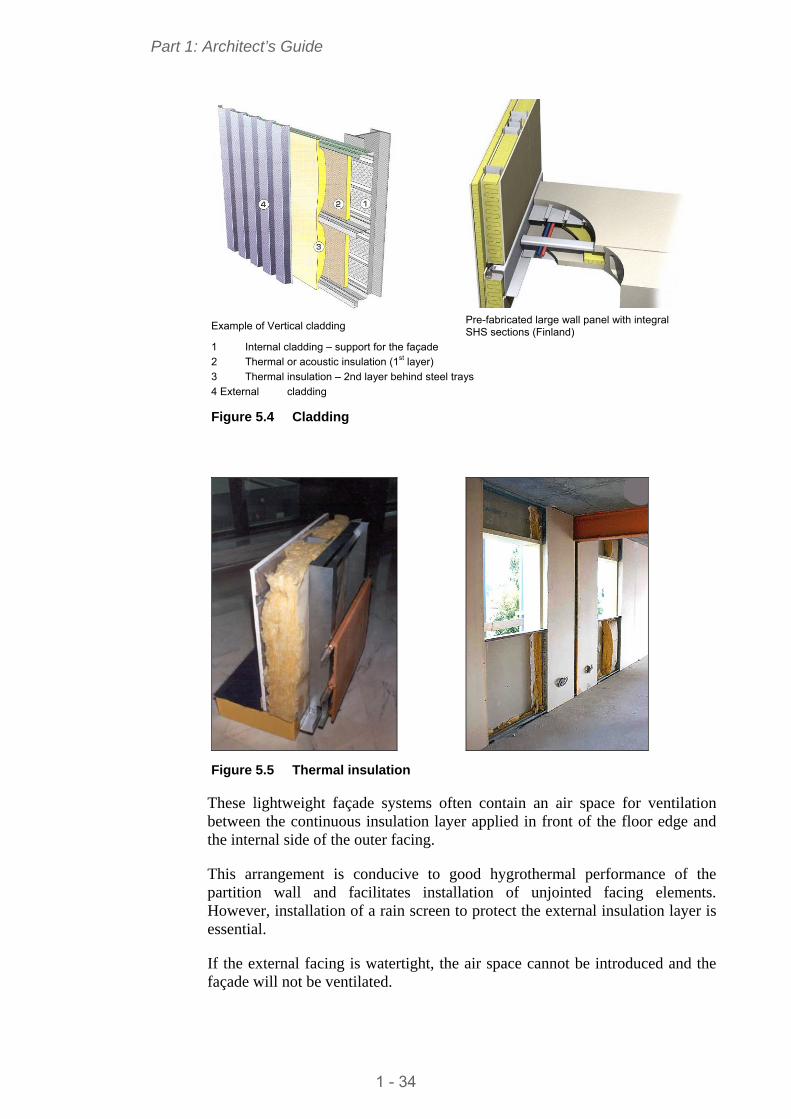
Pre-fabricated large wall panel with integral SHS sections (Finland) Example of Vertical cladding
1 Internal cladding – support for the façade 2 Thermal or acoustic insulation (1st layer) 3 Thermal insulation – 2nd layer behind steel trays 4 External cladding
Figure 5.4 Cladding
Figure 5.5 Thermal insulation
These lightweight façade systems often contain an air space for ventilation between the continuous insulation layer applied in front of the floor edge and the internal side of the outer facing.
This arrangement is conducive to good hygrothermal performance of the partition wall and facilitates installation of unjointed facing elements. However, installation of a rain screen to protect the external insulation layer is essential.
If the external facing is watertight, the air space cannot be introduced and the façade will not be ventilated.
1 - 34
Part 1: Architect’s Guide
Fram
e AX
IS
Inte
rnal
sid
e of
ext
erna
l ski
n
SLAB
6
24
1
3
57
Fram
e AX
IS
Inte
rnal
sid
e of
ext
erna
l ski
n
4
2
SLAB
81
3
6
Detail for bottom of infill walls Detail for top of infill walls
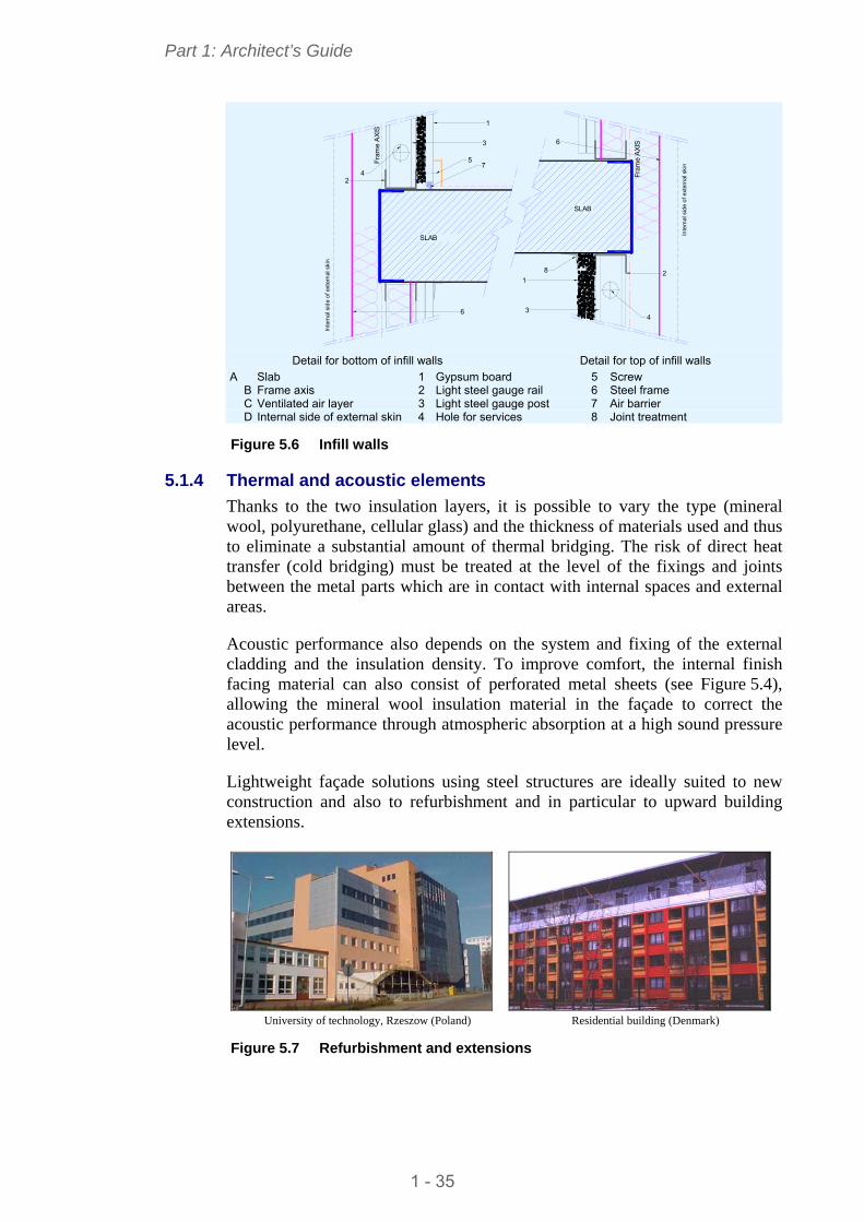
A Slab 1 Gypsum board 5 Screw B Frame axis 2 Light steel gauge rail 6 Steel frame C Ventilated air layer 3 Light steel gauge post 7 Air barrier D Internal side of external skin 4 Hole for services 8 Joint treatment Figure 5.6 Infill walls
5.1.4 Thermal and acoustic elements
Thanks to the two insulation layers, it is possible to vary the type (mineral wool, polyurethane, cellular glass) and the thickness of materials used and thus to eliminate a substantial amount of thermal bridging. The risk of direct heat transfer (cold bridging) must be treated at the level of the fixings and joints between the metal parts which are in contact with internal spaces and external areas.
Acoustic performance also depends on the system and fixing of the external cladding and the insulation density. To improve comfort, the internal finish facing material can also consist of perforated metal sheets (see Figure 5.4), allowing the mineral wool insulation material in the façade to correct the acoustic performance through atmospheric absorption at a high sound pressure level.
Lightweight façade solutions using steel structures are ideally suited to new construction and also to refurbishment and in particular to upward building extensions.
University of technology, Rzeszow (Poland) Residential building (Denmark)
Figure 5.7 Refurbishment and extensions
1 - 35
Part 1: Architect’s Guide
Table 5.1 Comparative weights of façades and partitions
Type of façade Weight (kg/m2)
Heavy façade: - Bearing wall of 18 cm - 8 cm outside insulation - Terracotta or stone facing 20 to 50 cm
80-100 (wall not included)
Light façade: - Secondary frame of façade (cold-formed profiles) - A layer of mineral wool - Partition of dubbing of 0,07 cm - Outside finish facing - steel tray
30-50
Concrete wall of 20 cm 500
2 H-shaped columns of 0,20 m 1 I-shaped beam of 0,27 m Light partitions of 0,20 m
30-50 depending on the use
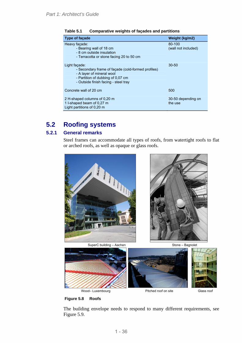
5.2 Roofing systems 5.2.1 General remarks
Steel frames can accommodate all types of roofs, from watertight roofs to flat or arched roofs, as well as opaque or glass roofs.
SuperC building – Aachen Stone – Bagnolet
Wood– Luxembourg Pitched roof on site Glass roof
Figure 5.8 Roofs
The building envelope needs to respond to many different requirements, see Figure 5.9.
1 - 36
Part 1: Architect’s Guide
WIND
SNOW, Maintenance
WIND
Watertightness Pressure and depression External and internal hygrometry Durability Accessibility and maintenance
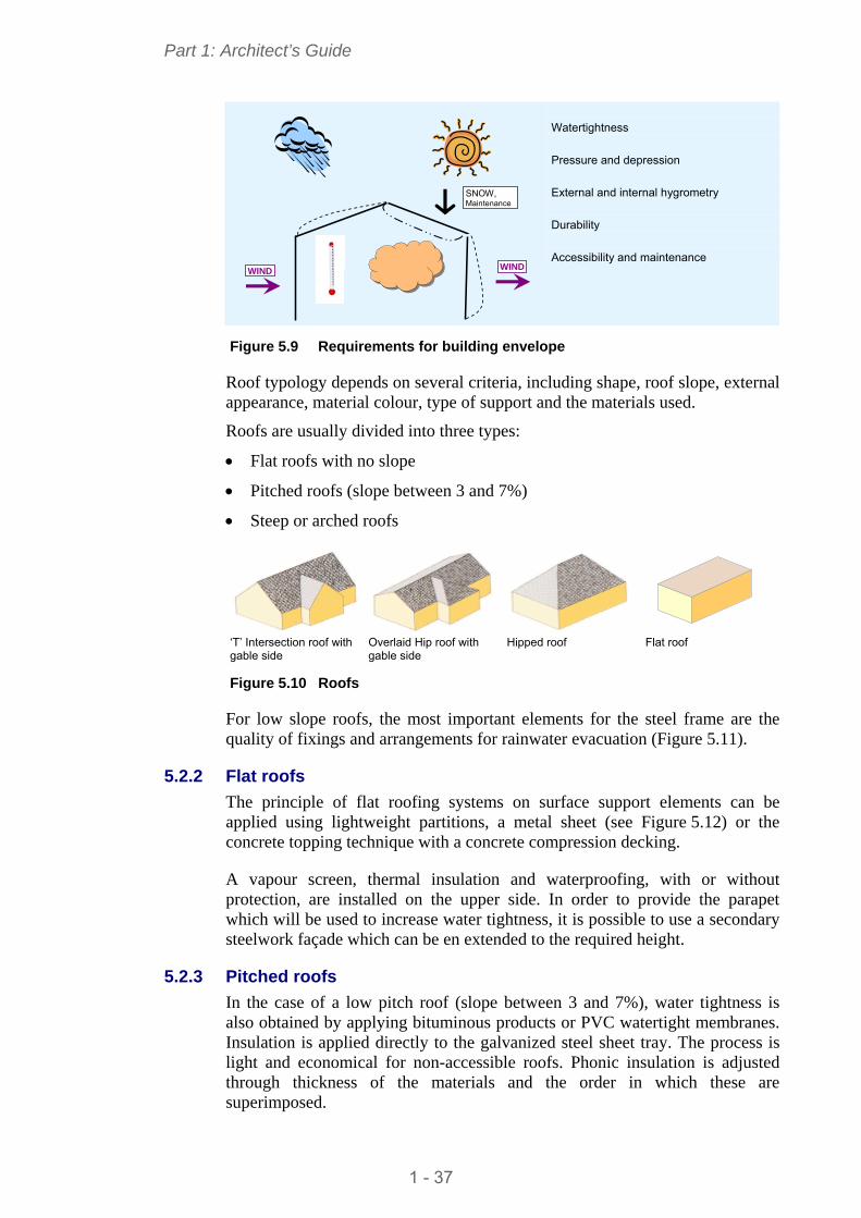
Figure 5.9 Requirements for building envelope
Roof typology depends on several criteria, including shape, roof slope, external appearance, material colour, type of support and the materials used.
Roofs are usually divided into three types:
Flat roofs with no slope
Pitched roofs (slope between 3 and 7%)
Steep or arched roofs
‘T’ Intersection roof with gable side
Overlaid Hip roof with gable side
Hipped roof Flat roof
Figure 5.10 Roofs
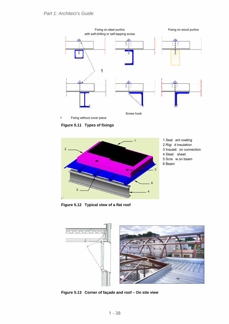
For low slope roofs, the most important elements for the steel frame are the quality of fixings and arrangements for rainwater evacuation (Figure 5.11).
5.2.2 Flat roofs
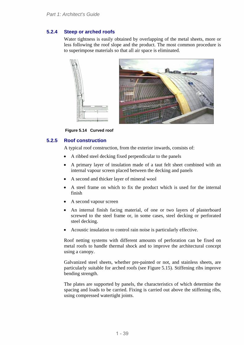
The principle of flat roofing systems on surface support elements can be applied using lightweight partitions, a metal sheet (see Figure 5.12) or the concrete topping technique with a concrete compression decking.
A vapour screen, thermal insulation and waterproofing, with or without protection, are installed on the upper side. In order to provide the parapet which will be used to increase water tightness, it is possible to use a secondary steelwork façade which can be en extended to the required height.
5.2.3 Pitched roofs
In the case of a low pitch roof (slope between 3 and 7%), water tightness is also obtained by applying bituminous products or PVC watertight membranes. Insulation is applied directly to the galvanized steel sheet tray. The process is light and economical for non-accessible roofs. Phonic insulation is adjusted through thickness of the materials and the order in which these are superimposed.
1 - 37
Part 1: Architect’s Guide
Fixing on steel purlins with self-drilling or self-tapping screw
Fixing on wood purlins
1
Screw hook
1 Fixing without cover piece Figure 5.11 Types of fixings
1 Seal ant coating
4
1
3
2
5
6
2 Rigi d insulation 3 Insulati on connection 4 Steel sheet 5 Scre w on beam 6 Beam
Figure 5.12 Typical view of a flat roof
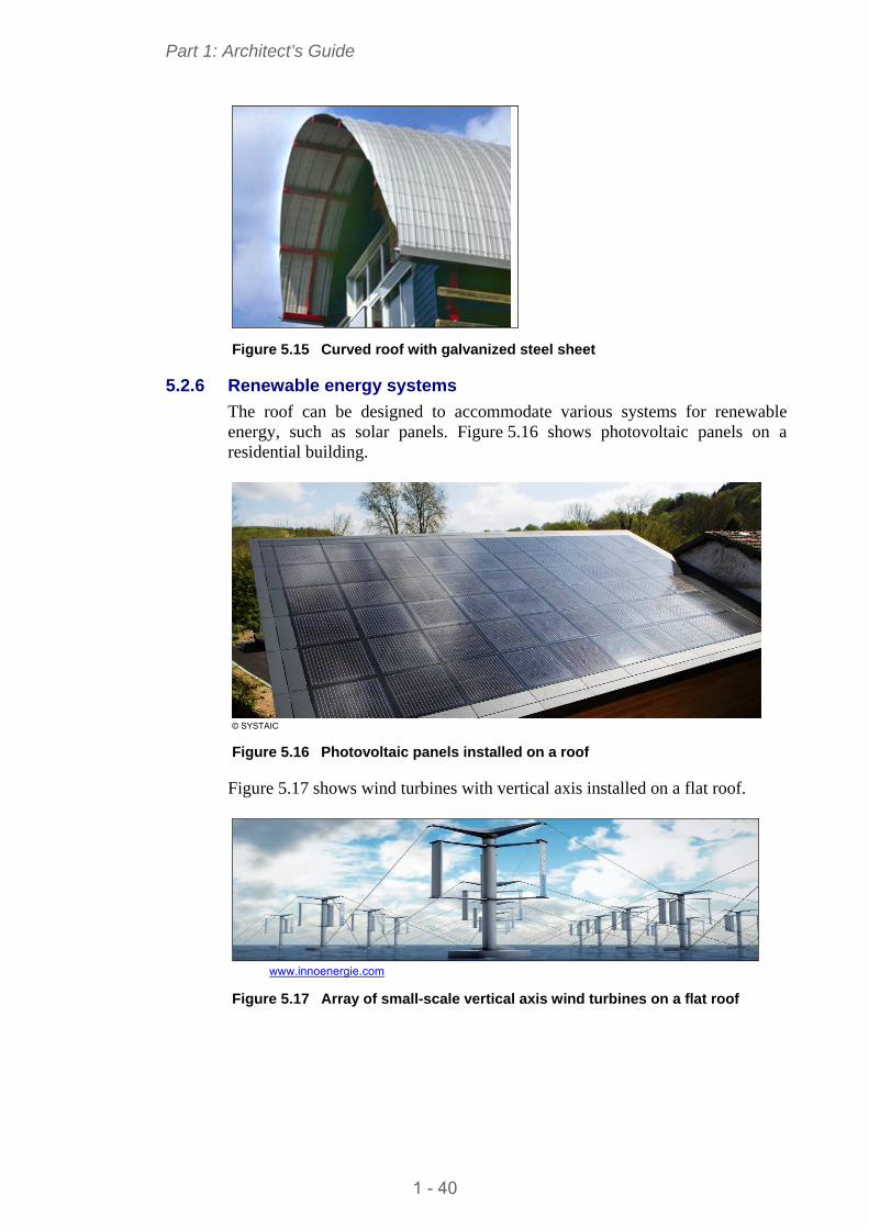
Figure 5.13 Corner of façade and roof – On site view
1 - 38
Part 1: Architect’s Guide
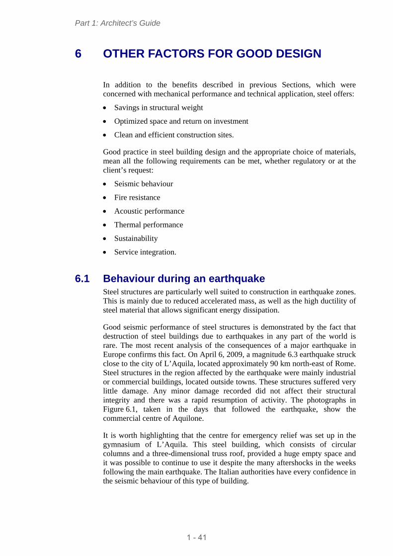
5.2.4 Steep or arched roofs
Water tightness is easily obtained by overlapping of the metal sheets, more or less following the roof slope and the product. The most common procedure is to superimpose materials so that all air space is eliminated.
Figure 5.14 Curved roof
5.2.5 Roof construction
A typical roof construction, from the exterior inwards, consists of:
A ribbed steel decking fixed perpendicular to the panels
A primary layer of insulation made of a taut felt sheet combined with an internal vapour screen placed between the decking and panels
A second and thicker layer of mineral wool
A steel frame on which to fix the product which is used for the internal finish
A second vapour screen
An internal finish facing material, of one or two layers of plasterboard screwed to the steel frame or, in some cases, steel decking or perforated steel decking.
Acoustic insulation to control rain noise is particularly effective.
Roof netting systems with different amounts of perforation can be fixed on metal roofs to handle thermal shock and to improve the architectural concept using a canopy.
Galvanized steel sheets, whether pre-painted or not, and stainless sheets, are particularly suitable for arched roofs (see Figure 5.15). Stiffening ribs improve bending strength.
The plates are supported by panels, the characteristics of which determine the spacing and loads to be carried. Fixing is carried out above the stiffening ribs, using compressed watertight joints.
1 - 39
Part 1: Architect’s Guide
Figure 5.15 Curved roof with galvanized steel sheet
5.2.6 Renewable energy systems
The roof can be designed to accommodate various systems for renewable energy, such as solar panels. Figure 5.16 shows photovoltaic panels on a residential building.
© SYSTAIC
Figure 5.16 Photovoltaic panels installed on a roof
Figure 5.17 shows wind turbines with vertical axis installed on a flat roof.
www.innoenergie.com
Figure 5.17 Array of small-scale vertical axis wind turbines on a flat roof
1 - 40
Part 1: Architect’s Guide
6 OTHER FACTORS FOR GOOD DESIGN
In addition to the benefits described in previous Sections, which were concerned with mechanical performance and technical application, steel offers:
Savings in structural weight
Optimized space and return on investment
Clean and efficient construction sites.
Good practice in steel building design and the appropriate choice of materials, mean all the following requirements can be met, whether regulatory or at the client’s request:
Seismic behaviour
Fire resistance
Acoustic performance
Thermal performance
Sustainability
Service integration.
6.1 Behaviour during an earthquake Steel structures are particularly well suited to construction in earthquake zones. This is mainly due to reduced accelerated mass, as well as the high ductility of steel material that allows significant energy dissipation.
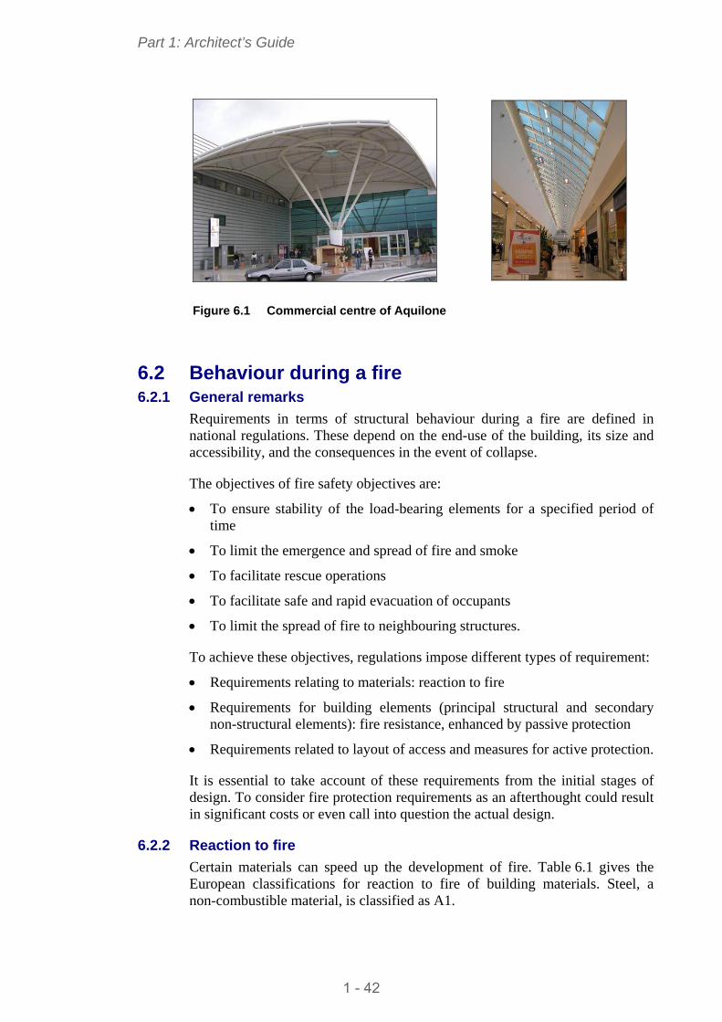
Good seismic performance of steel structures is demonstrated by the fact that destruction of steel buildings due to earthquakes in any part of the world is rare. The most recent analysis of the consequences of a major earthquake in Europe confirms this fact. On April 6, 2009, a magnitude 6.3 earthquake struck close to the city of L’Aquila, located approximately 90 km north-east of Rome. Steel structures in the region affected by the earthquake were mainly industrial or commercial buildings, located outside towns. These structures suffered very little damage. Any minor damage recorded did not affect their structural integrity and there was a rapid resumption of activity. The photographs in Figure 6.1, taken in the days that followed the earthquake, show the commercial centre of Aquilone.
It is worth highlighting that the centre for emergency relief was set up in the gymnasium of L’Aquila. This steel building, which consists of circular columns and a three-dimensional truss roof, provided a huge empty space and it was possible to continue to use it despite the many aftershocks in the weeks following the main earthquake. The Italian authorities have every confidence in the seismic behaviour of this type of building.
1 - 41
Part 1: Architect’s Guide
Figure 6.1 Commercial centre of Aquilone
6.2 Behaviour during a fire 6.2.1 General remarks
Requirements in terms of structural behaviour during a fire are defined in national regulations. These depend on the end-use of the building, its size and accessibility, and the consequences in the event of collapse.
The objectives of fire safety objectives are:
To ensure stability of the load-bearing elements for a specified period of time
To limit the emergence and spread of fire and smoke
To facilitate rescue operations
To facilitate safe and rapid evacuation of occupants
To limit the spread of fire to neighbouring structures.
To achieve these objectives, regulations impose different types of requirement:
Requirements relating to materials: reaction to fire
Requirements for building elements (principal structural and secondary non-structural elements): fire resistance, enhanced by passive protection
Requirements related to layout of access and measures for active protection.
It is essential to take account of these requirements from the initial stages of design. To consider fire protection requirements as an afterthought could result in significant costs or even call into question the actual design.
6.2.2 Reaction to fire
Certain materials can speed up the development of fire. Table 6.1 gives the European classifications for reaction to fire of building materials. Steel, a non-combustible material, is classified as A1.
1 - 42
Part 1: Architect’s Guide
Table 6.1 European classification for building materials
Class Comment
A1 non-combustible products No contribution, even in highly developed fire. Must automatically satisfy other less stringent classes
A2 non-combustible and not very combustible products
Class B + little contribution to fire load and to development of fire in event of very developed fire
B combustible products Item C with even stricter criteria C combustible products Item D with stricter criteria D combustible products Product resisting attack of small flame for longer period.
Capable of undergoing thermal attack from isolated object on fire with delayed and limited heat release
E combustible products Products capable of resisting attack by small flame without substantial spread
F unclassified products No fire reaction performance defined
The system provides additional classifications, as given in Table 6.2.
Table 6.2 Additional classes
Production of inflamed smoke Production of droplets or debris
S1 low smoke production d0 absence of inflamed droplets S2 medium smoke production d1 no inflamed droplets exceeding 10 seconds S3 no limit required d2 inflamed droplets (persistence > 10 seconds)
6.2.3 Fire resistance
Resistance to fire is the ability of a building element to continue to perform its intended function in fire.
The fire resistance classification of a building element is defined by:
Standardized criteria (see Table 6.3)
Degree of fire resistance (duration, expressed in minutes, before reaching criteria)
It measures the fire performance of the classified element.
Requirements for fire resistance of building elements are expressed in terms of a classification criterion and a time for which the criterion must be satisfied.
Table 6.3 Classification for building elements
Criteria Definitions
Mechanical resistance: ability to resist thermal attack from fire without loss of structural stability
R
Air tightness in a fire: ability to prevent spread of flames and hot gases E Thermal insulation: ability to prevent increase in temperature of side not exposed to fire I Thermal radiation: ability not to emit thermal radiation greater than 15 kW/m² W
The classification of a construction element may be:
R, RE, E, REI or EI, followed by the time in minutes -15, 30, 60, 90, 120 minutes, etc.
Additional criteria and criteria specific to certain facilities are also given - see Table 6.4.
1 - 43
Part 1: Architect’s Guide
Table 6.4 Additional and specific criteria
Criteria Additional criteria
Air tightness to cold smoke: Prevents propagation of smoke in fire, even if relatively cold
S
Automatic shut down: Door, valve or shutter closes automatically C
Resistance to impact: Vertical partition to resist lateral mechanical shock M
Criteria Specific criteria
Outlet ducts for smoke (30 min): Outlet duct removes hot gases during the first 30 minutes
B0
Barriers (30 min): Confine hot gases and smoke during initial 30 minutes D Smoke vents (30 min): Remove hot gases and smoke during initial 30 minutes F
Tests or calculations are needed to demonstrate or justify the fire performance of a building element or product. Tests are defined by standards which define the methods and experiments to be undertaken for a specific type of behaviour.
Calculations can be based on conventional approaches (constant increase in temperature over time), or on the new approach to fire safety engineering introduced by the Eurocodes, through advances in knowledge about the behaviour and development of fire.
6.2.4 Passive fire protection methods
As with other materials, the strength and stiffness of steel decrease at elevated temperatures.
Conventional fire resistance of an unprotected steel section rarely exceeds 30 minutes when subjected to normal levels of loading.
Passive fire protection is therefore used to slow down the heating of steel structures in order to give the required fire resistance.
A number of systems are available: these are listed below. They provide the steel structure with the appropriate levels of protection, regardless of building end-use. They are sometimes combined.
Screen protection
Screen protection isolates the structure from an advancing fire by the interposition of elements that form a continuous wall. In a vertical position they serve as wall panels; when horizontal, they are suspended ceilings. All products used must have been tested for fire resistance.
The screen should be chosen for its fire resistance properties and can be used for acoustic and thermal insulation, as well as for aesthetic reasons.
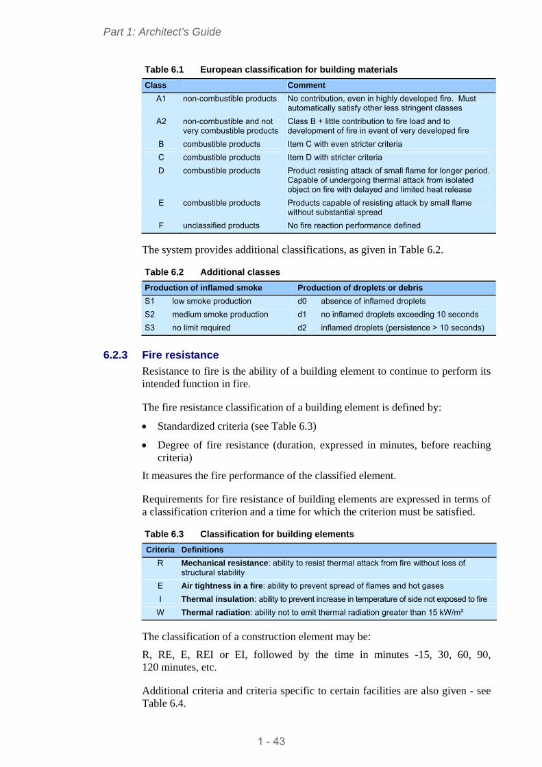
Spray applied fire protection This is the most common form of protection. There are two basic sorts of product, thick film and thin film.
1 - 44
Part 1: Architect’s Guide
Figure 6.2 Fire protection
With thick film coatings, the spray product or coating is fibrous or paste-like. It is generally composed of mineral fibres, vermiculite, slag or gypsum, together with a binder. It is sprayed on with special equipment under wet conditions. Several layers may be necessary, which increases the drying time.
Fire protection can last up to 4 hours.
Thin film coatings, called intumescent coatings, have a special property - they swell heat. When cold, the film thickness is between 0.5 and 4 mm. When heated to a temperature between 100° C and 200° C, the film swells and turns into foam, reaching thicknesses of 30 to 40 mm; this protects the steel element.
These paints are applied with a spray or brush and careful application of the products ensures that protection is uniform.
Conserving the aesthetic appearance of the steel is the main advantage in this type of protection, which can last up to 120 minutes.
Board protection
Board protection is achieved by forming a casing around the steel element. This is done with mechanical fasteners (screws, staples) or adhesive. The boards are made of gypsum, vermiculite, mineral fibre or calcium silicate compounds.
The principle consists in.
The passage of hot gases into the joints is a risk and requires special attention during application. This solution must be very carefully applied.
Performance may reach R120.
1 - 45
Part 1: Architect’s Guide
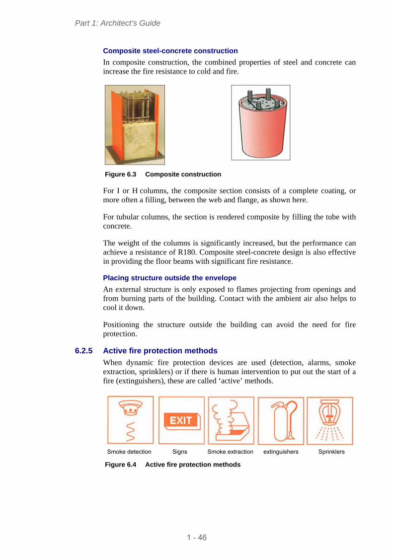
Composite steel-concrete construction
In composite construction, the combined properties of steel and concrete can increase the fire resistance to cold and fire.
Figure 6.3 Composite construction
For I or H columns, the composite section consists of a complete coating, or more often a filling, between the web and flange, as shown here.
For tubular columns, the section is rendered composite by filling the tube with concrete.
The weight of the columns is significantly increased, but the performance can achieve a resistance of R180. Composite steel-concrete design is also effective in providing the floor beams with significant fire resistance.
Placing structure outside the envelope An external structure is only exposed to flames projecting from openings and from burning parts of the building. Contact with the ambient air also helps to cool it down.
Positioning the structure outside the building can avoid the need for fire protection.
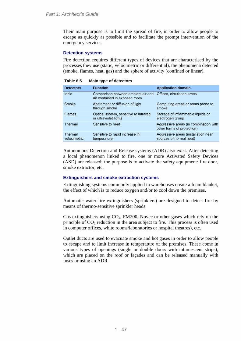
6.2.5 Active fire protection methods
When dynamic fire protection devices are used (detection, alarms, smoke extraction, sprinklers) or if there is human intervention to put out the start of a fire (extinguishers), these are called ‘active’ methods.
Smoke detection Signs Smoke extraction extinguishers Sprinklers Figure 6.4 Active fire protection methods
1 - 46
Part 1: Architect’s Guide
Their main purpose is to limit the spread of fire, in order to allow people to escape as quickly as possible and to facilitate the prompt intervention of the emergency services.
Detection systems
Fire detection requires different types of devices that are characterised by the processes they use (static, velocimetric or differential), the phenomena detected (smoke, flames, heat, gas) and the sphere of activity (confined or linear).
Table 6.5 Main type of detectors
Detectors Function Application domain
Ionic Comparison between ambient air and air contained in exposed room
Offices, circulation areas
Smoke Abatement or diffusion of light through smoke
Computing areas or areas prone to smoke
Flames Optical system, sensitive to infrared or ultraviolet light)
Storage of inflammable liquids or electrogen group
Thermal Sensitive to heat Aggressive areas (in combination with other forms of protection)
Thermal velocimetric
Sensitive to rapid increase in temperature
Aggressive areas (installation near sources of normal heat)
Autonomous Detection and Release systems (ADR) also exist. After detecting a local phenomenon linked to fire, one or more Activated Safety Devices (ASD) are released; the purpose is to activate the safety equipment: fire door, smoke extractor, etc.
Extinguishers and smoke extraction systems
Extinguishing systems commonly applied in warehouses create a foam blanket, the effect of which is to reduce oxygen and/or to cool down the premises.
Automatic water fire extinguishers (sprinklers) are designed to detect fire by means of thermo-sensitive sprinkler heads.
Gas extinguishers using CO2, FM200, Novec or other gases which rely on the principle of CO2 reduction in the area subject to fire. This process is often used in computer offices, white rooms/laboratories or hospital theatres), etc.
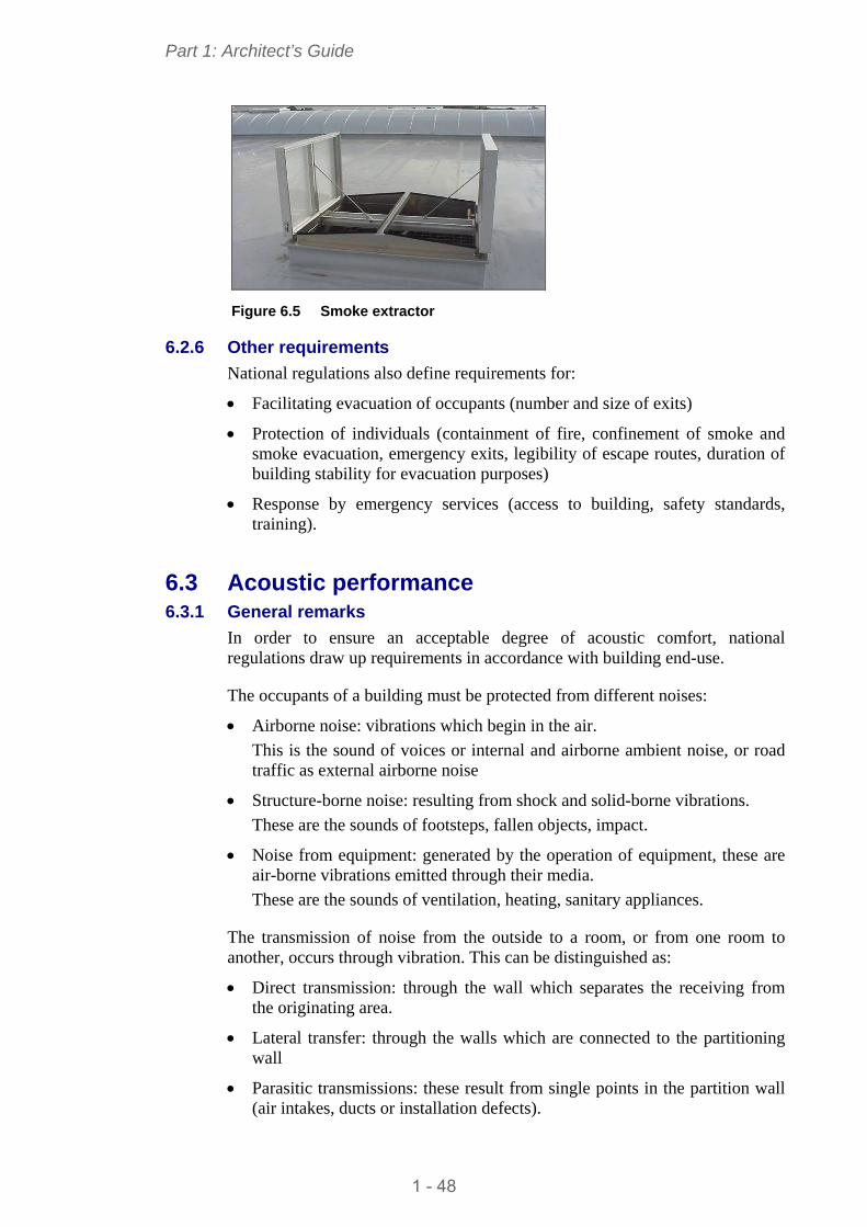
Outlet ducts are used to evacuate smoke and hot gases in order to allow people to escape and to limit increase in temperature of the premises. These come in various types of openings (single or double doors with intumescent strips), which are placed on the roof or façades and can be released manually with fuses or using an ADR.
1 - 47
Part 1: Architect’s Guide
Figure 6.5 Smoke extractor
6.2.6 Other requirements
National regulations also define requirements for:
Facilitating evacuation of occupants (number and size of exits)
Protection of individuals (containment of fire, confinement of smoke and smoke evacuation, emergency exits, legibility of escape routes, duration of building stability for evacuation purposes)
Response by emergency services (access to building, safety standards, training).
6.3 Acoustic performance 6.3.1 General remarks
In order to ensure an acceptable degree of acoustic comfort, national regulations draw up requirements in accordance with building end-use.
The occupants of a building must be protected from different noises:
Airborne noise: vibrations which begin in the air.
This is the sound of voices or internal and airborne ambient noise, or road traffic as external airborne noise
Structure-borne noise: resulting from shock and solid-borne vibrations.
These are the sounds of footsteps, fallen objects, impact.
Noise from equipment: generated by the operation of equipment, these are air-borne vibrations emitted through their media.
These are the sounds of ventilation, heating, sanitary appliances.
The transmission of noise from the outside to a room, or from one room to another, occurs through vibration. This can be distinguished as:
Direct transmission: through the wall which separates the receiving from the originating area.
Lateral transfer: through the walls which are connected to the partitioning wall
Parasitic transmissions: these result from single points in the partition wall (air intakes, ducts or installation defects).
1 - 48

Part 1: Architect’s Guide
Acoustic insulation provided by a partition lies in its ability to resist the transmission of sound from one side to the other. The sound reduction index is used to measure the performance of the wall. This is expressed in dB.
Regulations set minimum values for this index as a function of the building end-use, of the type of facilities being separated and for the airborne sound, impact sound and equipment noise.
It should be noted that the insulation provided by a real wall is always less than the index measured in the laboratory, because of lateral transfer and parasitic resonance.
The acoustic behaviour of a wall is illustrated by applying the mass-spring-mass law:
The acoustic reduction index increases with the surface density of the wall
For a double skin wall (two sandwich panels), this index depends on:
- Mass per unit area of each partition
- Thickness of the air space between partitions
- Thickness of acoustic absorption
- Critical frequency of each partition
The index of a double skin wall is much greater than a single wall with the same surface density. (The sound emitted from a room and spreading to another room horizontally and vertically passes through first layer of products which causes an initial reduction. It is then ‘trapped’ in the central void of the wall, where it bounces against the second partition and is absorbed by the insulation layer before returning residually through the second partition wall).
The acoustic performance of a steel building depends on the composition of the various partitions: external and internal, vertical and horizontal. Construction solutions are available which can achieve the very highest levels of performance.
6.3.2 Partitioning
Partitioning usually consists of thin, cold formed steel elements on which plasterboard sheets of varying thicknesses are screwed onto both sides. This creates a central air cavity in which one or more layers of insulating mineral wool are inserted.
It can incorporate the main structural building elements.
The composition of a partition wall can be adapted to the required level of performance by varying the following parameters:
Thickness of the air cavity: the more this increases, the higher the acoustic performance; the size of the main structural elements governs the choice of thickness
Composition of each facing (number and type of plates finished in plaster)
1 - 49
Part 1: Architect’s Guide
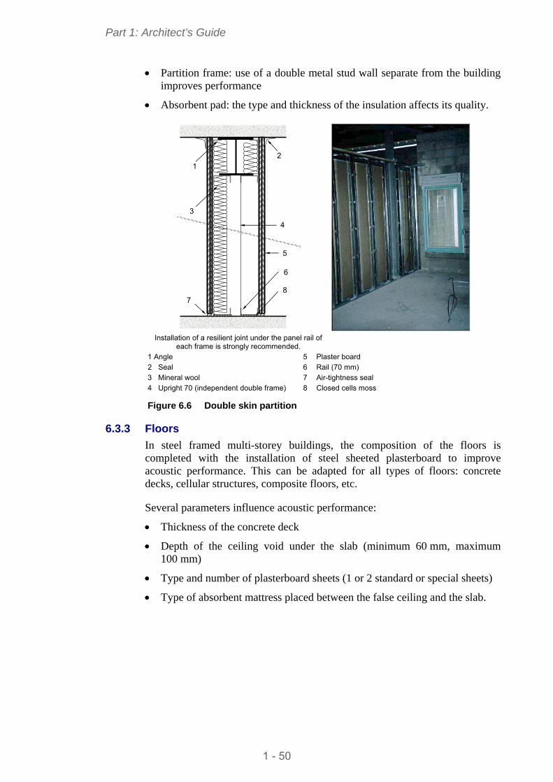
Partition frame: use of a double metal stud wall separate from the building improves performance
Absorbent pad: the type and thickness of the insulation affects its quality.
21
3
4
5
7
6
8
Installation of a resilient joint under the panel rail of
each frame is strongly recommended.
1 Angle 5 Plaster board 2 Seal 6 Rail (70 mm) 3 Mineral wool 7 Air-tightness seal 4 Upright 70 (independent double frame) 8 Closed cells moss
Figure 6.6 Double skin partition
6.3.3 Floors
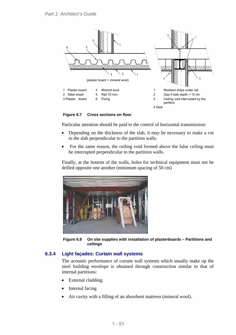
In steel framed multi-storey buildings, the composition of the floors is completed with the installation of steel sheeted plasterboard to improve acoustic performance. This can be adapted for all types of floors: concrete decks, cellular structures, composite floors, etc.
Several parameters influence acoustic performance:
Thickness of the concrete deck
Depth of the ceiling void under the slab (minimum 60 mm, maximum 100 mm)
Type and number of plasterboard sheets (1 or 2 standard or special sheets)
Type of absorbent mattress placed between the false ceiling and the slab.
1 - 50
Part 1: Architect’s Guide
1
3
5
6
4 1
2
(plaster board + mineral wool)
1 2
3 4
1 Plaster board 4 Mineral wool 2 Steel sheet 5 Rail 70 mm 3 Plaster board 6 Fixing
1 Resilient strips under rail 2 Gap if slab depth < 15 cm 3 Ceiling void interrupted by the
partition 4 Seal
Figure 6.7 Cross sections on floor
Particular attention should be paid to the control of horizontal transmission:
Depending on the thickness of the slab, it may be necessary to make a cut in the slab perpendicular to the partition walls.
For the same reason, the ceiling void formed above the false ceiling must be interrupted perpendicular to the partition walls.
Finally, at the bottom of the walls, holes for technical equipment must not be drilled opposite one another (minimum spacing of 50 cm)
Figure 6.8 On site supplies with installation of plasterboards – Partitions and
ceilings
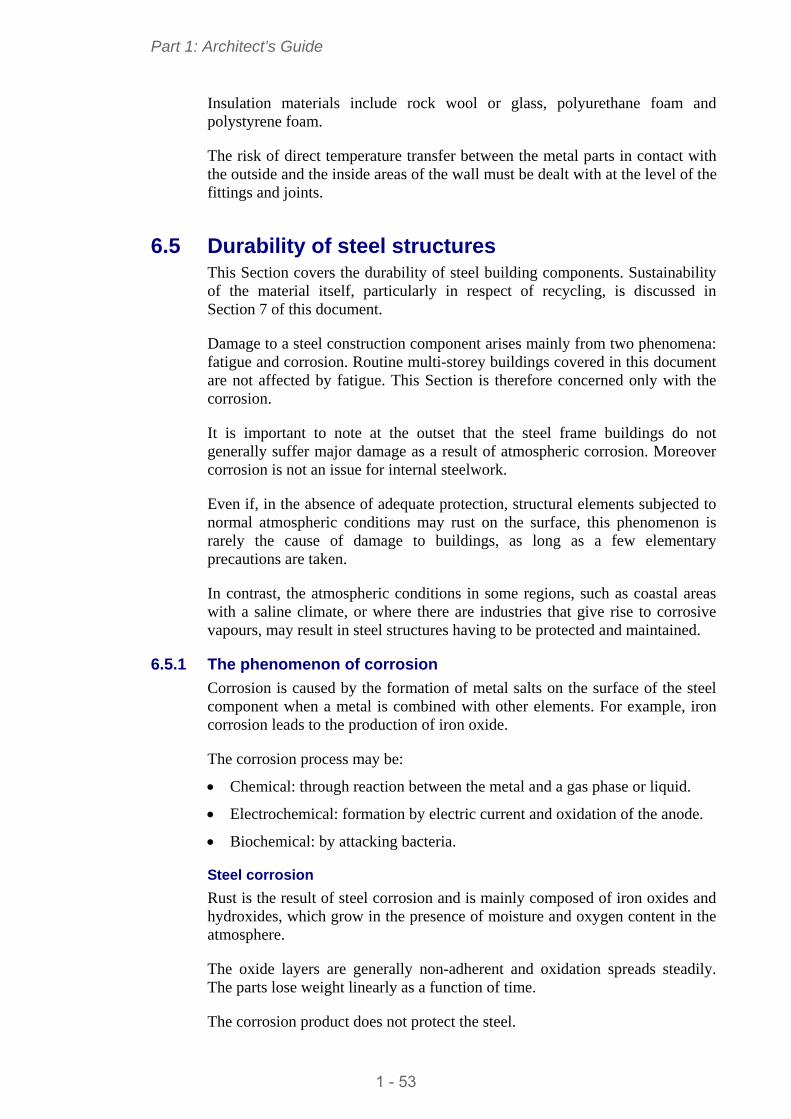
6.3.4 Light façades: Curtain wall systems
The acoustic performance of curtain wall systems which usually make up the steel building envelope is obtained through construction similar to that of internal partitions:
External cladding
Internal facing
Air cavity with a filling of an absorbent mattress (mineral wool).
1 - 51
Part 1: Architect’s Guide
The careful application of all these façade components is a pre-requisite to ensuring a satisfactory efficiency.
NO
YES
At the intersection with the wall, these facings must be separated by the partition wall. Likewise, vertically, the internal facings of the lining continue as far as the decking, by stopping the suspended ceiling
Figure 6.9 Horizontal cross section at the junction between façade and
partition
6.3.5 Steel roofing systems
There are special techniques for treatment of metal roofing (film or spraying) in order to reduce the noise of impact caused by rain.
6.4 Thermal performance In order to guarantee an acceptable level of thermal comfort for the occupants of buildings with controlled energy consumption, national regulations determine the material requirements for thermal performance. These depend on the building end-use and location.
The requirements can be defined in terms of:
Restrictions on energy consumption needed for thermal comfort
Restrictions on indoor temperature during the summer
Minimum thermal characteristics of envelope and equipment (restricting heat loss – effect of thermal bridging).
Section 6.3 dealt with different ways of conforming with regulatory requirements for the acoustic performance of steel buildings. The provisions do for the various partitions typically use mineral wool as a mattress in the composite walls and its presence in the walls that surround the rooms also protects them from heat loss.
Between two floors, for example, calorific loss is reduced because layers of mineral wool are used in the composition of the floors (above and below).
Separating the two layers of insulation means that the type and thickness of the materials can be varied, thereby eliminating a large amount of thermal bridging.
1 - 52
Part 1: Architect’s Guide
Insulation materials include rock wool or glass, polyurethane foam and polystyrene foam.
The risk of direct temperature transfer between the metal parts in contact with the outside and the inside areas of the wall must be dealt with at the level of the fittings and joints.
6.5 Durability of steel structures This Section covers the durability of steel building components. Sustainability of the material itself, particularly in respect of recycling, is discussed in Section 7 of this document.
Damage to a steel construction component arises mainly from two phenomena: fatigue and corrosion. Routine multi-storey buildings covered in this document are not affected by fatigue. This Section is therefore concerned only with the corrosion.
It is important to note at the outset that the steel frame buildings do not generally suffer major damage as a result of atmospheric corrosion. Moreover corrosion is not an issue for internal steelwork.
Even if, in the absence of adequate protection, structural elements subjected to normal atmospheric conditions may rust on the surface, this phenomenon is rarely the cause of damage to buildings, as long as a few elementary precautions are taken.
In contrast, the atmospheric conditions in some regions, such as coastal areas with a saline climate, or where there are industries that give rise to corrosive vapours, may result in steel structures having to be protected and maintained.
6.5.1 The phenomenon of corrosion
Corrosion is caused by the formation of metal salts on the surface of the steel component when a metal is combined with other elements. For example, iron corrosion leads to the production of iron oxide.
The corrosion process may be:
Chemical: through reaction between the metal and a gas phase or liquid.
Electrochemical: formation by electric current and oxidation of the anode.
Biochemical: by attacking bacteria.
Steel corrosion
Rust is the result of steel corrosion and is mainly composed of iron oxides and hydroxides, which grow in the presence of moisture and oxygen content in the atmosphere.
The oxide layers are generally non-adherent and oxidation spreads steadily. The parts lose weight linearly as a function of time.
The corrosion product does not protect the steel.
1 - 53
Part 1: Architect’s Guide
Atmosphere and climate are parameters that have a significant influence on the aggressiveness of corrosion.
Atmosphere
The general atmospheric conditions at the building location affect the rate of corrosion: there are four general conditions:
Rural: alternation of wet and dry atmosphere – absence of pollutants
Urban: alternation of wet and dry conditions – present of sulphur dioxide (SO2)
Marine: high relative humidity – presence of chlorides which accelerate corrosion.
Industrial: presence of chemical agents – aggressive corrosion linked to degree and rate of pollutants
Climate
Heat and humidity are factors which accelerate the phenomenon of corrosion. In tropical climates, aggressive corrosion in rural environments is comparable with that in large industrial areas in temperate climates.
Some elementary precautions
In steel construction design, every means of limiting the effects of corrosion should be adopted:
Avoid creating areas of moisture and water retention for elements which are exposed to weather
Avoid contact between materials which have different electro-chemical potentials (e.g. aluminium and unprotected steel).
Protection of steel construction elements
It is advisable to adapt the degree of protection to the conditions in which the steel construction elements are installed.
There are two main forms of protection:
Painting
Galvanizing.
6.5.2 Paint protection
Table 6.6 summarizes common coating systems for corrosion protection.
It is worth noting that steel structures located inside a building where the atmospheric conditions are neither wet nor aggressive, and are permanently protected from the weather, would not suffer corrosion to the extent that it affects their resistance, even if they were not protected. However, what cannot be excluded is the unattractive appearance of rust: this can be prevented by applying a light paint coating.
Surfaces which remain unprotected must be visible in order to detect any unexpected degree of corrosion.
1 - 54
Part 1: Architect’s Guide
Table 6.6 Protection and thickness of coating
Conditions of use Traditional anti-rust coating Coated steel products
Elements incorporated in floors and façades, protected in absence of humidity
1 or 2 primer layers of anti-rust paint, 40 to 50 microns thick
Lacquered and painted products: 15-20 microns thick
Elements inside buildings without constant humidity
1 primer of anti-rust paint, 1 paint finish, 60 to 80 microns thick
Lacquered and painted products. 1 paint finish. 60 microns thick
Elements inside unheated buildings or where humidity is high
2 primers of anti-rust paint. 1 intermediate layer of paint, 1 finish of paint, 80 to120 microns thick
Lacquered and painted products: 1 to 2 finishes of paint 80 to100 microns thick or Galvanized or pre-lacquered products
Elements in contact with aggressive external atmosphere, humid climate, urban or industrial regions
2 primer layers of anti-rust paint, 1 intermediary layer of anti-rust paint, 1 finish of anti-rust paint, 120 to 200 microns thick
Lacquered and painted products + 2 finishes of paint 100-120 microns thick Or: Galvanized or pre-lacquered products
Elements in contact with marine environment
2 primers of anti-rust paint or galvanizing/metalizing with 1 layer of zinc 1 intermediary layer of anti-rust paint, 1 paint finish, more than 150 microns thick
Lacquered or painted products+ 2 layers of paint with high content of zinc or Galvanizing or metalizing + paint with high content of zinc Or: Pre-lacquered products
The steel elements are usually delivered to site with a surface coating consisting of an anti-rust primer. Once the elements are installed, it is necessary to touch up any coating which has deteriorated during assembly.
Although elements embedded in concrete are generally not painted, those parts which are not fully covered by concrete are often prone to corrosion and must be carefully protected (including column ends).
For those parts of the elements concerned, the welds are performed and checked before applying surface protection. The welding procedure must be adapted for pre-painted products.
Estimated life of paint protection: 8 to 10 years to first maintenance
1 - 55
Part 1: Architect’s Guide
6.5.3 Protection by galvanizing
The principle of galvanizing is the formation of protective layer of zinc and zinc-steel alloy on the surface of the steel parts in order to protect against corrosion.
The galvanized layer which is gradually oxidized to form corrosion products that are generally adhesive.
However, this form of protection is time limited and loses its effectiveness when all of the zinc coating has corroded.
Speed of corrosion and life of protection
Atmospheric conditions and climate have a direct impact on the rate of corrosion. Polluted industrial conditions near the sea are obviously more aggressive than the rural hinterland.
Depending on atmospheric conditions, the corrosion rate varies between 0,1 microns/year and 8 microns/year.
EN ISO 14713[1] provides guidance on the average annual zinc corrosion rate. This allows lifetimes to be estimated according to the coating thickness.
Estimated life of protection by galvanizing: approximately 25 years
Aesthetic appearance and painting
All galvanized steel can be painted to alter the surface appearance. Painting greatly enhances the life of the galvanized steel. Maintenance painting of galvanized steel is very easy: a brush is used to apply new layer of paint to the damaged area. The paint can also be applied as an additional form of corrosion protection in environments where acidic solutions may attack the surface coating.
Galvanizing processes
Zinc can be applied either by immersion or spraying (metalizing solution) or by electrolysis. Immersion is generally used for new parts, for dimensions compatible with the size of the baths. Spraying is used instead for renovation work or for larger building elements. Electrolysis is suitable for small parts and batch processing (e.g. bolts).
Some observations
Welding: Before welding galvanized parts, it is recommended that the coating is removed in the area of the weld seam. After sealing, the affected area will be protected by a zinc-rich paint.
Exposure to fire: A galvanized steel part that is exposed to fire behaves like uncoated steel and there is no improvement in fire resistance.
1 - 56
Part 1: Architect’s Guide
6.6 Service integration 6.6.1 General remarks
A multi-story building, regardless of end use, is the combination of multiple elements or sub-elements that contribute to its performance: not only the structure and envelope, but also the technical installations and services which sustain the life of the building.
The control of interactions between the services and the building structure should allow:
Ease of access to services for maintenance purposes
Facility to replace elements where their life span is shorter than the structure
Prevention of nuisances arising from vibration of structures due to operation of equipment.
The main services to be installed are:
Heating and air conditioning,
Ventilation,
High and low current power supplies.
Services to the whole building are supplied using horizontal and vertical systems.
6.6.2 Horizontal systems
The steel structure and envelope offer very efficient methods of service integration using horizontal systems, as illustrated in Table 6.7. It is worth highlighting the use of cellular beams in this context (see sections 3 and 4 in this document for a description of these products). Since services can pass directly through these beams, the floor-to-floor height can be reduced. In some cases, this allows another floor to be added without altering the overall height of the building.
The standard configuration of cellular beams (regularly spaced cells of the same size) can generally be adapted to create larger openings, especially near the mid-span, in order to allow the passage of large rectangular ducts (Figure 6.10).
6.6.3 Vertical systems
Steel construction and standard envelope systems also offer flexible integration of vertical systems, due to open spaces in the wall thickness.
Achieving floor openings, and changing their location during the life of the building, is facilitated by the use of composite dry floors.
It is best to prevent the passage of services through hollow sections (between flange plates) because of potential problems with beam/column connections and in event of application of fire protection coating.
The integration of vertical pipes in tubular columns is not recommended because of lack of access for maintenance.
1 - 57
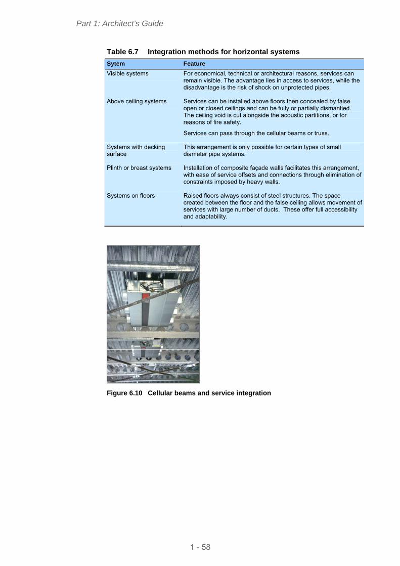
Part 1: Architect’s Guide
Table 6.7 Integration methods for horizontal systems
Sytem Feature
Visible systems For economical, technical or architectural reasons, services can remain visible. The advantage lies in access to services, while the disadvantage is the risk of shock on unprotected pipes.
Above ceiling systems Services can be installed above floors then concealed by false open or closed ceilings and can be fully or partially dismantled. The ceiling void is cut alongside the acoustic partitions, or for reasons of fire safety.
Services can pass through the cellular beams or truss.
Systems with decking surface
This arrangement is only possible for certain types of small diameter pipe systems.
Plinth or breast systems Installation of composite façade walls facilitates this arrangement, with ease of service offsets and connections through elimination of constraints imposed by heavy walls.
Systems on floors Raised floors always consist of steel structures. The space created between the floor and the false ceiling allows movement of services with large number of ducts. These offer full accessibility and adaptability.
Figure 6.10 Cellular beams and service integration
1 - 58
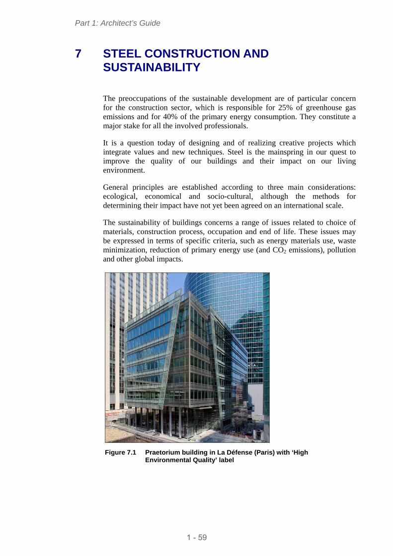
Part 1: Architect’s Guide
7 STEEL CONSTRUCTION AND SUSTAINABILITY
The preoccupations of the sustainable development are of particular concern for the construction sector, which is responsible for 25% of greenhouse gas emissions and for 40% of the primary energy consumption. They constitute a major stake for all the involved professionals.
It is a question today of designing and of realizing creative projects which integrate values and new techniques. Steel is the mainspring in our quest to improve the quality of our buildings and their impact on our living environment.
General principles are established according to three main considerations: ecological, economical and socio-cultural, although the methods for determining their impact have not yet been agreed on an international scale.
The sustainability of buildings concerns a range of issues related to choice of materials, construction process, occupation and end of life. These issues may be expressed in terms of specific criteria, such as energy materials use, waste minimization, reduction of primary energy use (and CO2 emissions), pollution and other global impacts.
Figure 7.1 Praetorium building in La Défense (Paris) with ‘High
Environmental Quality’ label
1 - 59
Part 1: Architect’s Guide
7.1 Life cycle Steel is an excellent solution for conserving raw materials, thanks to its recyclability. It can be infinitely recycled without losing its properties.
Today, the production of steel in Europe consists of 50% recycled metal, reducing the need for ore; for certain products intended for construction, this rate can reach up to 98%. This re-use of the material is in particular made possible by its magnetic properties facilitating the sorting.
For 25 years, the control of energy and the reduction of CO2 emissions during production have led to vast improvements in developing new steel materials and taking into account life cycle of materials and products. The European steel industry has substantially contributed to the energy efficiency and the reduction in CO2 emissions.
Between 1970 and 2005, the European steel industry reduced CO2 emissions by 60%; between 1990 and 2005, this reduction was 21% (source Eurofer). In the same period, crude steel production increased by 11.5% (source Worldsteel for EU15).
Other solutions are already underway to improve these results.
Steel is a neutral material which emits no polluting substance or element that is harmful to the environment or health, even under the influence of corrosion.
Galvanizing and painting (carried out in the factory) are corrosion protection systems that guarantee the durability of steel up to 25 years.
Maintenance of steel is limited to regular follow-up and periodic painting.
7.2 Advantages of steel products for construction An Environmental Product Declaration (EPD) is now a widely developed approach for construction products. Based on ISO 21930[2] the overall goal of an EPD is to provide relevant, verified and comparable information to meet various customer and market needs.
Using life cycle assessments, the steel industry has already provided several EPD for generic products as well as branded systems. The energy and lighting consumption during service life exceeds the embodied energy in the structure.
Thanks to the efficient use of materials, steel construction minimizes waste in manufacture and on-site, because all steel off-cuts and drills are sent for re-cycling into new steel components. Typically, the average steel wastage and re-use is about 2%, in comparison with the European average of 10% for all the products used on-site.
The excellent weight-resistance ratio of the material offers incomparable constructive and architectural possibilities. This performance opens the way to the reducing the weight in buildings, using thin walled structures in the façade. These features offer a large amount of space with light and vast possibilities for architectural integration.
1 - 60
Part 1: Architect’s Guide
The association of steel with other materials offers many efficient solutions for thermal and acoustic insulation.
For the envelope, the metallic construction is generally designed with an external thermal insulation; walls are built from industrialized systems, metallic or not (glass, wood, concrete, terra-cotta, plaster, etc.), which offer high levels of thermal performance. The heating and ventilation systems can then be chosen for optimal energy behaviour.
The range of qualities opens the architectural choices and allows the optimized selection of the processes, the materials and the methods of construction, especially by considering the global life of the building to be realized up to its demolition.
7.3 Steel-intensive solutions for buildings For buildings there are several environmental initiatives across Europe. These approaches can be quantitative or qualitative, using variable criteria. However, some subjects are common, but with different treatments, for which steel solutions bring firm answers.
The harmonious integration of the building with its surrounding environment
The choice of a steel frame for a building project allows the designer a large freedom of shape and the flexibility to adapt work to the constraints of the site.
Used for façades or roofing, steel products offer the architect a range of textures, geometries and colours to respond to the most sensitive and the varied of contemporary sites, whether a historical city centre or in the countryside.
Lightness of the structures and the flexibility of spaces
A frame made with columns and beams is typical in steel buildings. Without load-bearing walls, the construction is lighter; the impacts on the foundations and the ground are lesser.
It is also easier to remodel internal spaces according to the changes of use.
A structure with connected components is an efficient solution for vertical extensions as well as in the renovation of an existing building.
Less on-site problems
Steel products and associated elements are industrially made, of high precision. They are delivered with accurate dimensions for on-site assembly. Due to the higher level of pre-fabrication, implicit in steel-intensive constructions systems, speed of construction is increased.
The construction site is transformed, with reduced deliveries, precise and appropriate assembly, less storage and no waste.
Maintenance
Steel solutions provide durability and facilitate cleaning and replacement of components.
1 - 61
Part 1: Architect’s Guide
Services (fluids, ducts, etc) are generally placed in the ceiling void. The maintenance and the possible reconfiguration of the services are then facilitated, especially in the presence of cellular beams. This flexibility allows the different levels to be completely refitted.
At the end of life, the demolition consists of a clean dismantling, for a complete recovery of materials.
Re-use of steel profiles
In Western Europe, a study has shown that about 11% of profiles in the construction sector are directly reused after demolition, without remoulding (ECSC Report ‘LCA for steel construction’. Document RT913. July 2002. Steel Construction Institute).
Creating a safe and comfortable internal space
All combinations of wall components can be accommodated.
Steel solutions in combination with additional products contribute to the excellent sound insulation through the ‘mass-spring-mass’ principle.
For thermal comfort, steel allows the design of ‘evolved’ façades, adapted to the various climatic conditions:
Double-skin façades, implementation of a layer of ventilated air,
Fixed or mobile solar control mechanisms
Integration of alternative technologies on steel buildings
Alternative Energy Technologies (AET) are integrated into building design for a wide range of reasons but typically the primary motivators are green aspirations and planning restraints such as ‘Grenelle’, which will require a certain percentage of a building’s energy consumption to be provided by additional benefits from using AET, including renewable energy.
AET provide environmental benefits over the use of standard energy supply. Moreover, they have a very low impact on steel buildings. The main concerns for AETs implantation are:
Plant Room: The location of the plant room and spatial restrictions can impact on the viability of specific technologies
Shading: the shape of the new building may restrict the location of solar PV panels.
Roof Orientation: The orientation and the shape of the roof can be a limitation on energy output, for either solar hot water collectors or photovoltaic panels.
Reliability: If an unproven technology is used then it may not be reliable and so the desired carbon savings cannot be made.
1 - 62
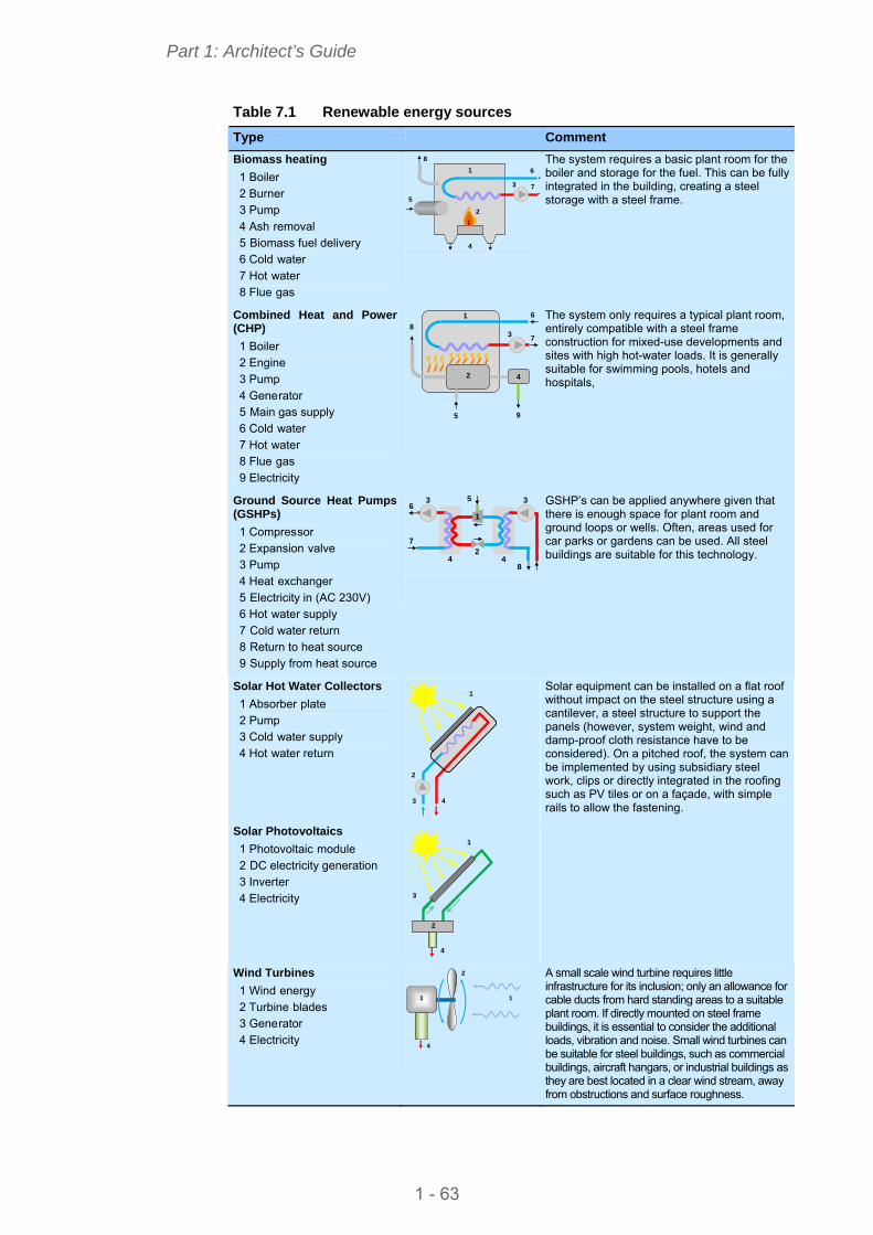
Part 1: Architect’s Guide
Table 7.1 Renewable energy sources
Type Comment
Biomass heating
1 Boiler 2 Burner 3 Pump 4 Ash removal 5 Biomass fuel delivery 6 Cold water 7 Hot water 8 Flue gas
5
2
4
6
7
1
8
3
The system requires a basic plant room for the boiler and storage for the fuel. This can be fully integrated in the building, creating a steel storage with a steel frame.
Combined Heat and Power (CHP) 1 Boiler 2 Engine 3 Pump 4 Generator 5 Main gas supply 6 Cold water 7 Hot water 8 Flue gas 9 Electricity
9
2
5
4
6
7
1
8 3
The system only requires a typical plant room, entirely compatible with a steel frame construction for mixed-use developments and sites with high hot-water loads. It is generally suitable for swimming pools, hotels and hospitals,
Ground Source Heat Pumps (GSHPs) 1 Compressor 2 Expansion valve 3 Pump 4 Heat exchanger 5 Electricity in (AC 230V) 6 Hot water supply 7 Cold water return 8 Return to heat source 9 Supply from heat source
5
8
7
6 3 3
4 4
1
2
GSHP’s can be applied anywhere given that there is enough space for plant room and ground loops or wells. Often, areas used for car parks or gardens can be used. All steel buildings are suitable for this technology.
Solar Hot Water Collectors 1 Absorber plate 2 Pump 3 Cold water supply 4 Hot water return
3
1
4
2
Solar Photovoltaics
Solar equipment can be installed on a flat roof without impact on the steel structure using a cantilever, a steel structure to support the panels (however, system weight, wind and damp-proof cloth resistance have to be considered). On a pitched roof, the system can be implemented by using subsidiary steel work, clips or directly integrated in the roofing such as PV tiles or on a façade, with simple rails to allow the fastening.
1 Photovoltaic module
3
1
4
2 DC electricity generation 3 Inverter 4 Electricity
2
Wind Turbines
3 1
2
4
1 Wind energy 2 Turbine blades 3 Generator 4 Electricity
A small scale wind turbine requires little infrastructure for its inclusion; only an allowance for cable ducts from hard standing areas to a suitable plant room. If directly mounted on steel frame buildings, it is essential to consider the additional loads, vibration and noise. Small wind turbines can be suitable for steel buildings, such as commercial buildings, aircraft hangars, or industrial buildings as they are best located in a clear wind stream, away from obstructions and surface roughness.
1 - 63
Part 1: Architect’s Guide
8 CONCLUSION
Thanks to its outstanding mechanical performance, to the freedom of technical prowess it affords, to its flexibility of use in different types of buildings, to its plastic and aesthetic potential and the creativity it inspires, steel has a natural place in the pantheon of materials for architectural design.
When an architect chooses steel, he knows this is a choice of no small consequence. First this choice implies rigorous design, awareness of the functionality of each of the elements that make up the design, and analysis of all stages in the building process – from drawing board to routine management of the completed project. Second, the choice is an expression of affirmation, of putting ones mark on a design, a way of conceiving and perceiving, a willingness to contribute to the urban landscape, to integrate with light and air into the urban fabric. Steel is a form of expression which gives meaning to architectural design.
Choosing steel to design a multi-storey building is to choose a material which offers low cost, strength, durability, design flexibility, adaptability and recyclability. It also means choosing reliable industrial products which come in a huge range of shapes and colours; it means rapid site installation and less energy consumption. It means choosing to commit to the principles of sustainability. Infinitely recyclable, steel is the material that reflects the imperatives of sustainable development. In conclusion, choosing steel means choosing a greater freedom of construction, of architecture. It means injecting style into the buildings and the cities of tomorrow.
1 - 64

Part 1: Architect’s Guide
1 - 65
REFERENCES
1 EN ISO 14713 Zinc coatings. Guidelines and recommendations for the protection against corrosion of iron and steel in structures.
2 ISO 21930:2007 Sustainability in building construction. Environmental declaration of building products
STEEL BUILDINGS IN EUROPE
Multi-Storey Steel Buildings
Part 2: Concept Design
.

Multi-Storey Steel Buildings
Part 2: Concept Design

2 - ii
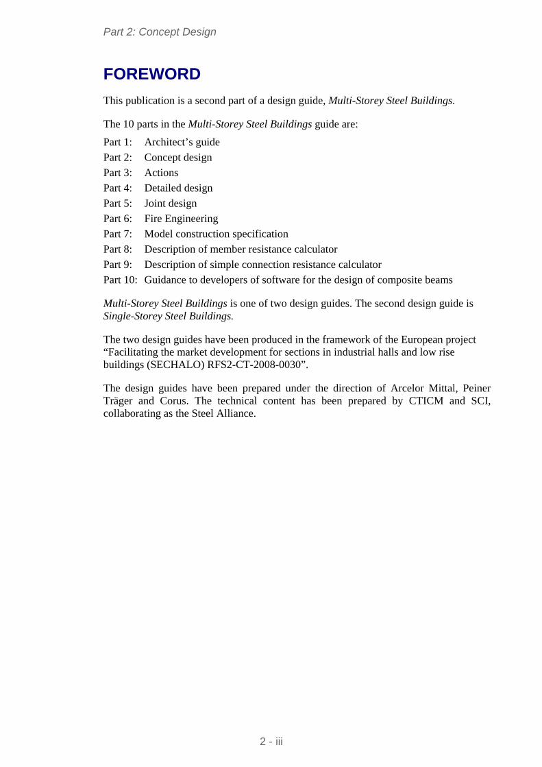
Part 2: Concept Design
FOREWORD
This publication is a second part of a design guide, Multi-Storey Steel Buildings.
The 10 parts in the Multi-Storey Steel Buildings guide are:
Part 1: Architect’s guide
Part 2: Concept design
Part 3: Actions
Part 4: Detailed design
Part 5: Joint design
Part 6: Fire Engineering
Part 7: Model construction specification
Part 8: Description of member resistance calculator
Part 9: Description of simple connection resistance calculator
Part 10: Guidance to developers of software for the design of composite beams
Multi-Storey Steel Buildings is one of two design guides. The second design guide is Single-Storey Steel Buildings.
The two design guides have been produced in the framework of the European project “Facilitating the market development for sections in industrial halls and low rise buildings (SECHALO) RFS2-CT-2008-0030”.
The design guides have been prepared under the direction of Arcelor Mittal, Peiner Träger and Corus. The technical content has been prepared by CTICM and SCI, collaborating as the Steel Alliance.
2 - iii

Part 2: Concept Design
2 - iv
Part 2: Concept Design
Contents
Page No
FOREWORD iii
SUMMARY vi
1 INTRODUCTION: STRUCTURAL DESIGN IN OVERALL BUILDING DESIGN 1 1.1 Hierarchy of design decisions 2 1.2 Client requirements 3 1.3 Economics 5 1.4 Construction programme 6 1.5 Sustainability 7
2 BENEFITS OF STEEL CONSTRUCTION 11 2.1 Speed of construction 11 2.2 Construction process 12 2.3 Long spans and service integration 13 2.4 Lightweight structures and resource efficiency 14 2.5 Benefits of adaptability 15
3 CASE STUDIES ON MULTI-STOREY STEEL BUILDINGS 16 3.1 Office Building, Bishops Square, London 16 3.2 Le Seguana, Paris 18 3.3 Luxembourg Chamber of Commerce 19 3.4 Kings Place, Kings Cross, London 20 3.5 Kone Headquarters, Helsinki 21 3.6 AM Steel Centre, Liege 22
4 ANATOMY OF BUILDING DESIGN 24 4.1 Floor grids 24 4.2 Dimensional coordination 25 4.3 Structural options for stability 27 4.4 Columns 30 4.5 Structural options for floor systems 31 4.6 Factors influencing structural arrangements 35 4.7 Structure – service integration 37
5 FLOOR SYSTEMS 40 5.1 Composite construction 40 5.2 Composite beams and composite slabs with steel decking 40 5.3 Long-span composite beams with web openings 45 5.4 Cellular composite beams with composite slab and steel decking 47 5.5 Composite beams with precast concrete units 50 5.6 Non-composite beams with precast units 53 5.7 Integrated beams with precast concrete units 55 5.8 Asymmetric beams and deep decking 59 5.9 Beam connections 60
6 OTHER DESIGN ISSUES 63 6.1 Accidental Actions 63 6.2 Floor dynamics 65 6.3 Corrosion protection 67 6.4 Temperature effects 67 6.5 Fire safety 67 6.6 Acoustic performance 68 6.7 Energy efficiency 70 6.8 Cladding 70
REFERENCES 75
2 - v
Part 2: Concept Design
2 - vi
SUMMARY
This publication presents information necessary to assist in the choice and use of steel structures at the concept design stage of modern multi-storey buildings. The primary sector of interest is commercial buildings, but the same information may also be used in other sectors. The information is presented in terms of the design strategy, anatomy of building design and structural systems that are relevant to the multi-storey buildings. This publication on the concept design of multi-storey frames complements other parts of the guide.
The use of long span composite construction is considered to be a very important step towards the greater use of steel in multi-storey buildings, and these forms of construction are emphasised in this publication. Cellular beams and perforated steel sections are promoted, as integrated solutions providing long spans without increasing overall floor depth. Long spans provide column-free adaptable space with fewer foundations. Integrated beams are also beneficial where the beam depth is minimised, such as in renovation applications. Other forms of floor construction, such as precast concrete units, are also covered.
Tables are provided for preliminary design of the various structural systems, with typical layouts, sizes and guidance on the key design issues.
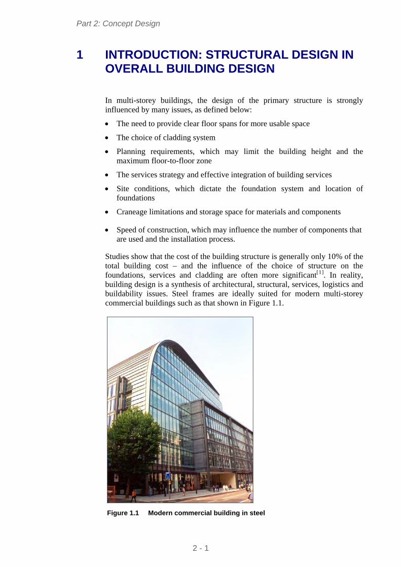
Part 2: Concept Design
1 INTRODUCTION: STRUCTURAL DESIGN IN OVERALL BUILDING DESIGN
In multi-storey buildings, the design of the primary structure is strongly influenced by many issues, as defined below:
The need to provide clear floor spans for more usable space
The choice of cladding system
Planning requirements, which may limit the building height and the maximum floor-to-floor zone
The services strategy and effective integration of building services
Site conditions, which dictate the foundation system and location of foundations
Craneage limitations and storage space for materials and components
Speed of construction, which may influence the number of components that are used and the installation process.
Studies show that the cost of the building structure is generally only 10% of the total building cost – and the influence of the choice of structure on the foundations, services and cladding are often more significant[1]. In reality, building design is a synthesis of architectural, structural, services, logistics and buildability issues. Steel frames are ideally suited for modern multi-storey commercial buildings such as that shown in Figure 1.1.
Figure 1.1 Modern commercial building in steel
2 - 1
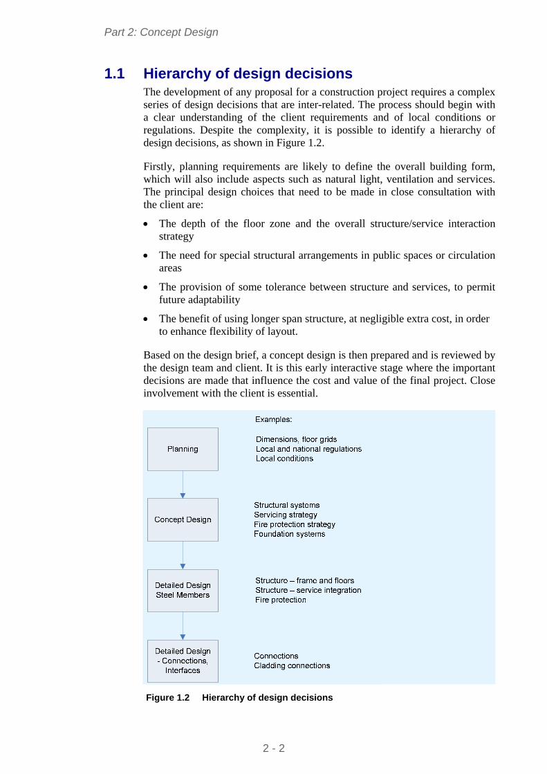
Part 2: Concept Design
1.1 Hierarchy of design decisions The development of any proposal for a construction project requires a complex series of design decisions that are inter-related. The process should begin with a clear understanding of the client requirements and of local conditions or regulations. Despite the complexity, it is possible to identify a hierarchy of design decisions, as shown in Figure 1.2.
Firstly, planning requirements are likely to define the overall building form, which will also include aspects such as natural light, ventilation and services. The principal design choices that need to be made in close consultation with the client are:
The depth of the floor zone and the overall structure/service interaction strategy
The need for special structural arrangements in public spaces or circulation areas
The provision of some tolerance between structure and services, to permit future adaptability
The benefit of using longer span structure, at negligible extra cost, in order to enhance flexibility of layout.
Based on the design brief, a concept design is then prepared and is reviewed by the design team and client. It is this early interactive stage where the important decisions are made that influence the cost and value of the final project. Close involvement with the client is essential.
Figure 1.2 Hierarchy of design decisions
2 - 2
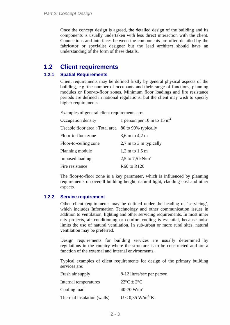
Part 2: Concept Design
Once the concept design is agreed, the detailed design of the building and its components is usually undertaken with less direct interaction with the client. Connections and interfaces between the components are often detailed by the fabricator or specialist designer but the lead architect should have an understanding of the form of these details.
1.2 Client requirements 1.2.1 Spatial Requirements
Client requirements may be defined firstly by general physical aspects of the building, e.g. the number of occupants and their range of functions, planning modules or floor-to-floor zones. Minimum floor loadings and fire resistance periods are defined in national regulations, but the client may wish to specify higher requirements.
Examples of general client requirements are:
Occupation density 1 person per 10 m to 15 m2
Useable floor area : Total area 80 to 90% typically
Floor-to-floor zone 3,6 m to 4,2 m
Floor-to-ceiling zone 2,7 m to 3 m typically
Planning module 1,2 m to 1,5 m
Imposed loading 2,5 to 7,5 kN/m2
Fire resistance R60 to R120
The floor-to-floor zone is a key parameter, which is influenced by planning requirements on overall building height, natural light, cladding cost and other aspects.
1.2.2 Service requirement
Other client requirements may be defined under the heading of ‘servicing’, which includes Information Technology and other communication issues in addition to ventilation, lighting and other servicing requirements. In most inner city projects, air conditioning or comfort cooling is essential, because noise limits the use of natural ventilation. In sub-urban or more rural sites, natural ventilation may be preferred.
Design requirements for building services are usually determined by regulations in the country where the structure is to be constructed and are a function of the external and internal environments.
Typical examples of client requirements for design of the primary building services are:
Fresh air supply 8-12 litres/sec per person
Internal temperatures 22C 2C
Cooling load 40-70 W/m2
Thermal insulation (walls) U < 0,35 W/m2K
2 - 3
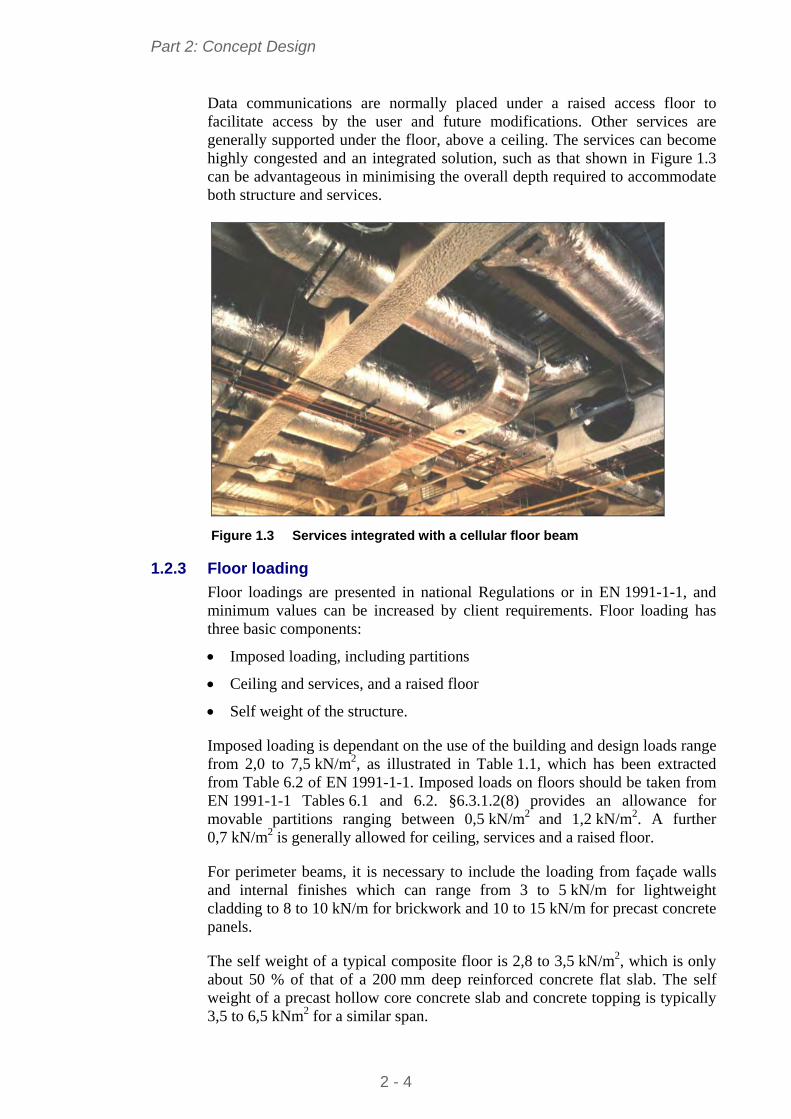
Part 2: Concept Design
Data communications are normally placed under a raised access floor to facilitate access by the user and future modifications. Other services are generally supported under the floor, above a ceiling. The services can become highly congested and an integrated solution, such as that shown in Figure 1.3 can be advantageous in minimising the overall depth required to accommodate both structure and services.
Figure 1.3 Services integrated with a cellular floor beam
1.2.3 Floor loading
Floor loadings are presented in national Regulations or in EN 1991-1-1, and minimum values can be increased by client requirements. Floor loading has three basic components:
Imposed loading, including partitions
Ceiling and services, and a raised floor
Self weight of the structure.
Imposed loading is dependant on the use of the building and design loads range from 2,0 to 7,5 kN/m2, as illustrated in Table 1.1, which has been extracted from Table 6.2 of EN 1991-1-1. Imposed loads on floors should be taken from EN 1991-1-1 Tables 6.1 and 6.2. §6.3.1.2(8) provides an allowance for movable partitions ranging between 0,5 kN/m2 and 1,2 kN/m2. A further 0,7 kN/m2 is generally allowed for ceiling, services and a raised floor.
For perimeter beams, it is necessary to include the loading from façade walls and internal finishes which can range from 3 to 5 kN/m for lightweight cladding to 8 to 10 kN/m for brickwork and 10 to 15 kN/m for precast concrete panels.
The self weight of a typical composite floor is 2,8 to 3,5 kN/m2, which is only about 50 % of that of a 200 mm deep reinforced concrete flat slab. The self weight of a precast hollow core concrete slab and concrete topping is typically 3,5 to 6,5 kNm2 for a similar span.
2 - 4
Part 2: Concept Design
Other typical weights are illustrated in Table 1.2.
Table 1.1 Typical imposed loads for offices (kN/m2)
En 1991-1-1 Category
Application Imposed Loading
Partitions Ceiling,
Services, etc.
B Offices - general 2,0 – 3,0 0,5 – 1,2 0,7
C1 Areas with tables 2,0 – 3,0 0,5 – 1,2 0,7
C2 Areas with fixed seats 3,0 – 4,0 0,5 – 1,2 0,7
C3 Areas open to crowds 3,0 – 5,0
C5 Areas open to large crowds
5,0 – 7,5
Table 1.2 Typical weights for building elements
Element Typical weight
Precast units (Spanning 6 m, designed for a 5 kN/m2 imposed load) 3,5 to 4,5 kN/m2
Composite slab (Normal weight concrete, 140 mm thick) 2,8 to 3,5 kN/m2
Composite slab (Light weight concrete, 130 mm thick) 2,1 to 2,5 kN/m2
Services (lighting) 0,25 kN/m2
Ceilings 0,1 kN/m2
Steelwork (low rise 2 to 6 storeys) 35 to 50 kg/m2
Steelwork (medium rise 7 to 12 storeys) 40 to 70 kg/m2
1.2.4 External Loading
Roofs are subject to imposed loads, to be taken from EN1991-1-1, typically 0,4 or 0,6 kN/m2.
Roofs are also subject to snow loads, which should be determined from EN 1991-1-3.
Wind loads should be calculated from EN 1991-1-4.
The determination of these loads is covered by other documents in this series[2].
1.3 Economics 1.3.1 Cost of construction
A breakdown of construction costs for a typical office building[1] is approximately as below:
Foundations 5-15%
Super structure and floors 10-15%
Cladding and roofing 15-25%
Services (mechanical and electrical) 15-25%
Services (sanitation and other services) 5-10%
Finishes, partitioning and fitments 10-20%
2 - 5
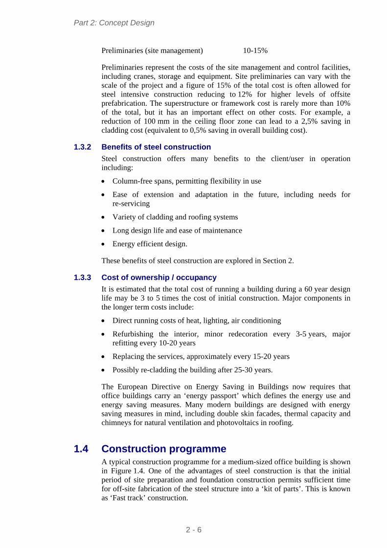
Part 2: Concept Design
Preliminaries (site management) 10-15%
Preliminaries represent the costs of the site management and control facilities, including cranes, storage and equipment. Site preliminaries can vary with the scale of the project and a figure of 15% of the total cost is often allowed for steel intensive construction reducing to 12% for higher levels of offsite prefabrication. The superstructure or framework cost is rarely more than 10% of the total, but it has an important effect on other costs. For example, a reduction of 100 mm in the ceiling floor zone can lead to a 2,5% saving in cladding cost (equivalent to 0,5% saving in overall building cost).
1.3.2 Benefits of steel construction
Steel construction offers many benefits to the client/user in operation including:
Column-free spans, permitting flexibility in use
Ease of extension and adaptation in the future, including needs for re-servicing
Variety of cladding and roofing systems
Long design life and ease of maintenance
Energy efficient design.
These benefits of steel construction are explored in Section 2.
1.3.3 Cost of ownership / occupancy
It is estimated that the total cost of running a building during a 60 year design life may be 3 to 5 times the cost of initial construction. Major components in the longer term costs include:
Direct running costs of heat, lighting, air conditioning
Refurbishing the interior, minor redecoration every 3-5 years, major refitting every 10-20 years
Replacing the services, approximately every 15-20 years
Possibly re-cladding the building after 25-30 years.
The European Directive on Energy Saving in Buildings now requires that office buildings carry an ‘energy passport’ which defines the energy use and energy saving measures. Many modern buildings are designed with energy saving measures in mind, including double skin facades, thermal capacity and chimneys for natural ventilation and photovoltaics in roofing.
1.4 Construction programme A typical construction programme for a medium-sized office building is shown in Figure 1.4. One of the advantages of steel construction is that the initial period of site preparation and foundation construction permits sufficient time for off-site fabrication of the steel structure into a ‘kit of parts’. This is known as ‘Fast track’ construction.
2 - 6
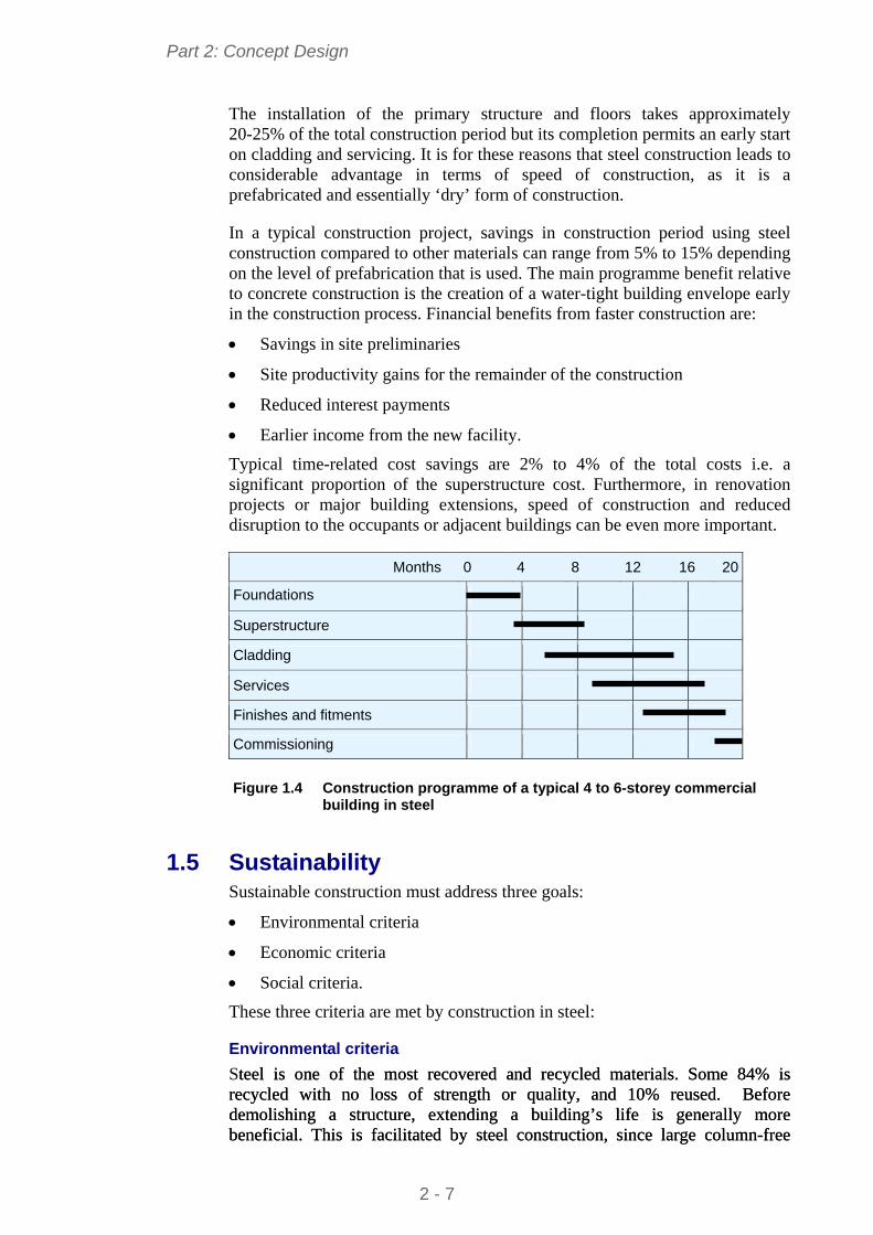
Part 2: Concept Design
The installation of the primary structure and floors takes approximately 20-25% of the total construction period but its completion permits an early start on cladding and servicing. It is for these reasons that steel construction leads to considerable advantage in terms of speed of construction, as it is a prefabricated and essentially ‘dry’ form of construction.
In a typical construction project, savings in construction period using steel construction compared to other materials can range from 5% to 15% depending on the level of prefabrication that is used. The main programme benefit relative to concrete construction is the creation of a water-tight building envelope early in the construction process. Financial benefits from faster construction are:
Savings in site preliminaries
Site productivity gains for the remainder of the construction
Reduced interest payments
Earlier income from the new facility.
Typical time-related cost savings are 2% to 4% of the total costs i.e. a significant proportion of the superstructure cost. Furthermore, in renovation projects or major building extensions, speed of construction and reduced disruption to the occupants or adjacent buildings can be even more important.
Months 0 4 8 12 16 20
Foundations
Superstructure
Cladding
Services
Finishes and fitments
Commissioning
Figure 1.4 Construction programme of a typical 4 to 6-storey commercial
building in steel
1.5 Sustainability Sustainable construction must address three goals:
Environmental criteria
Economic criteria
Social criteria.
These three criteria are met by construction in steel:
Environmental criteria
Steel is one of the most recovered and recycled materials. Some 84% is recycled with no loss of strength or quality, and 10% reused. Before demolishing a structure, extending a building’s life is generally more beneficial. This is facilitated by steel construction, since large column-free
teel is one of the most recovered and recycled materials. Some 84% is recycled with no loss of strength or quality, and 10% reused. Before demolishing a structure, extending a building’s life is generally more beneficial. This is facilitated by steel construction, since large column-free
2 - 7

Part 2: Concept Design
spaces give flexibility for change in use. Advances in the manufacturing of raw materials means that less water and energy is used in production, and allows for significant reductions in noise, particle and CO2 emissions.
Economic criteria
Steel construction brings together the various elements of a structure in an integrated design. The materials are manufactured, fabricated and constructed using efficient production processes. The use of material is highly optimised and waste virtually eliminated. The structures themselves are used for all aspects of modern life, including logistics, retail, commercial, and manufacturing, providing the infrastructure on which society depends. Steel construction provides low investment costs, optimum operational costs and outstanding flexibility of building use, with high quality, functionality, aesthetics and fast construction times.
Social criteria
The high proportion of offsite fabrication in steel buildings means that working conditions are safer, controlled and protected from the weather. A fixed location for employees helps to develop communities, family life and the skills. Steel releases no harmful substances into the environment, and steel buildings provide a robust, safe solution.
Multi-storey buildings
The design of multi-storey buildings is increasingly dependent on aspects of sustainability, defined by criteria such as:
Efficient use of materials and responsible sourcing of materials
Elimination of waste in manufacturing and in construction processes
Energy efficiency in building operation, including improved air-tightness
Measures to reduce water consumption
Improvement in indoor comfort
Overall management and planning criteria, such as public transport connections, aesthetics or preservation of ecological value.
Steel framed buildings can be designed to satisfy all these criteria. Some of the recognised sustainability benefits of steel are:
Steel structures are robust, with a long life. Properly detailed and maintained, steel structures can be used indefinitely
Approximately 10% of steel sections are re-used[3]
95% of structural steel sections are recycled
Steel products can potentially be dismantled and reused, particularly modular components or steel frames
Steel structures are lightweight for use on poor ground or over tunnels
Steel is manufactured efficiently in factory controlled processes
All waste is recycled in manufacture and no steel waste is produced on site
2 - 8
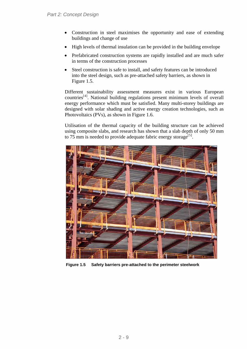
Part 2: Concept Design
Construction in steel maximises the opportunity and ease of extending buildings and change of use
High levels of thermal insulation can be provided in the building envelope
Prefabricated construction systems are rapidly installed and are much safer in terms of the construction processes
Steel construction is safe to install, and safety features can be introduced into the steel design, such as pre-attached safety barriers, as shown in Figure 1.5.
Different sustainability assessment measures exist in various European countries[4]. National building regulations present minimum levels of overall energy performance which must be satisfied. Many multi-storey buildings are designed with solar shading and active energy creation technologies, such as Photovoltaics (PVs), as shown in Figure 1.6.
Utilisation of the thermal capacity of the building structure can be achieved using composite slabs, and research has shown that a slab depth of only 50 mm to 75 mm is needed to provide adequate fabric energy storage[5].
Figure 1.5 Safety barriers pre-attached to the perimeter steelwork
2 - 9
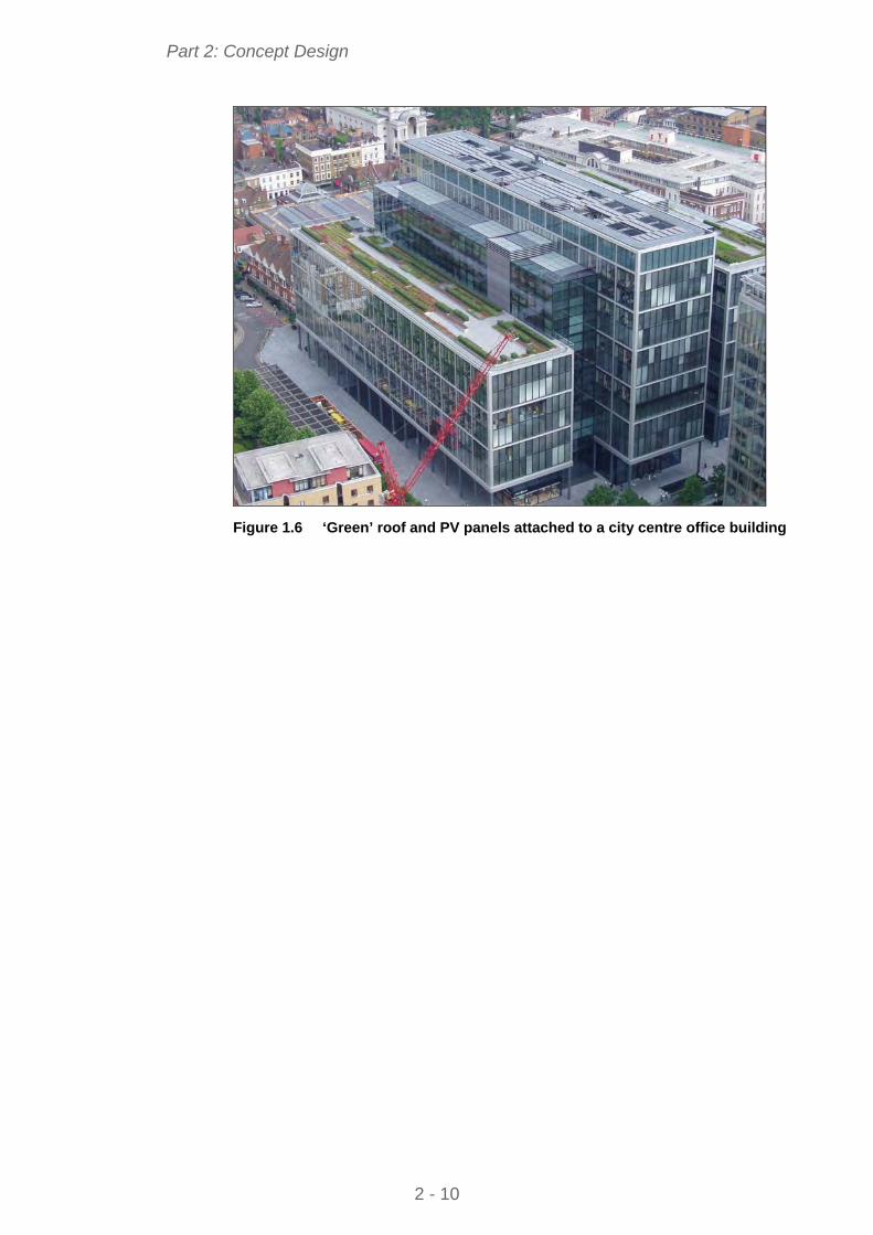
Part 2: Concept Design
Figure 1.6 ‘Green’ roof and PV panels attached to a city centre office building
2 - 10
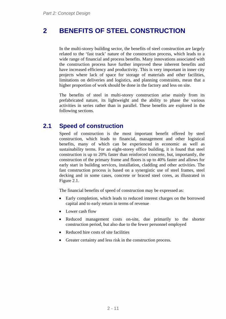
Part 2: Concept Design
2 BENEFITS OF STEEL CONSTRUCTION
In the multi-storey building sector, the benefits of steel construction are largely related to the ‘fast track’ nature of the construction process, which leads to a wide range of financial and process benefits. Many innovations associated with the construction process have further improved these inherent benefits and have increased efficiency and productivity. This is very important in inner city projects where lack of space for storage of materials and other facilities, limitations on deliveries and logistics, and planning constraints, mean that a higher proportion of work should be done in the factory and less on site.
The benefits of steel in multi-storey construction arise mainly from its prefabricated nature, its lightweight and the ability to phase the various activities in series rather than in parallel. These benefits are explored in the following sections.
2.1 Speed of construction Speed of construction is the most important benefit offered by steel construction, which leads to financial, management and other logistical benefits, many of which can be experienced in economic as well as sustainability terms. For an eight-storey office building, it is found that steel construction is up to 20% faster than reinforced concrete, but, importantly, the construction of the primary frame and floors is up to 40% faster and allows for early start in building services, installation, cladding and other activities. The fast construction process is based on a synergistic use of steel frames, steel decking and in some cases, concrete or braced steel cores, as illustrated in Figure 2.1.
The financial benefits of speed of construction may be expressed as:
Early completion, which leads to reduced interest charges on the borrowed capital and to early return in terms of revenue
Lower cash flow
Reduced management costs on-site, due primarily to the shorter construction period, but also due to the fewer personnel employed
Reduced hire costs of site facilities
Greater certainty and less risk in the construction process.
2 - 11
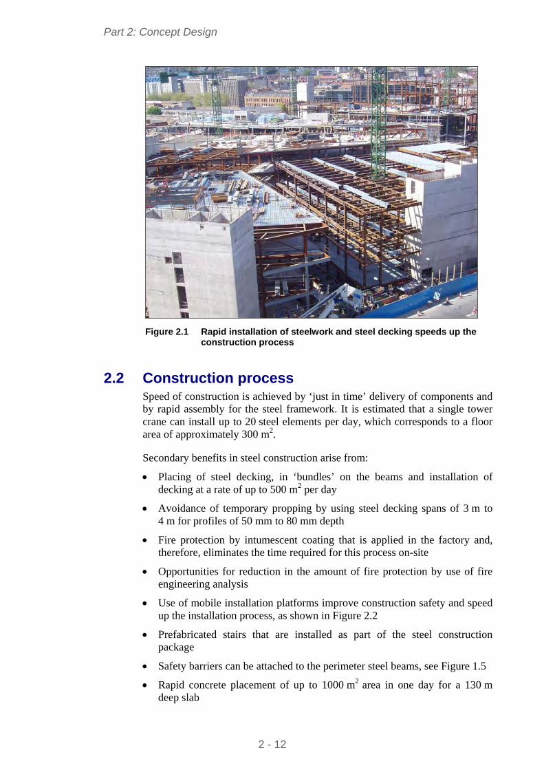
Part 2: Concept Design
Figure 2.1 Rapid installation of steelwork and steel decking speeds up the
construction process
2.2 Construction process Speed of construction is achieved by ‘just in time’ delivery of components and by rapid assembly for the steel framework. It is estimated that a single tower crane can install up to 20 steel elements per day, which corresponds to a floor area of approximately 300 m2.
Secondary benefits in steel construction arise from:
Placing of steel decking, in ‘bundles’ on the beams and installation of decking at a rate of up to 500 m2 per day
Avoidance of temporary propping by using steel decking spans of 3 m to 4 m for profiles of 50 mm to 80 mm depth
Fire protection by intumescent coating that is applied in the factory and, therefore, eliminates the time required for this process on-site
Opportunities for reduction in the amount of fire protection by use of fire engineering analysis
Use of mobile installation platforms improve construction safety and speed up the installation process, as shown in Figure 2.2
Prefabricated stairs that are installed as part of the steel construction package
Safety barriers can be attached to the perimeter steel beams, see Figure 1.5
Rapid concrete placement of up to 1000 m2 area in one day for a 130 m deep slab
2 - 12
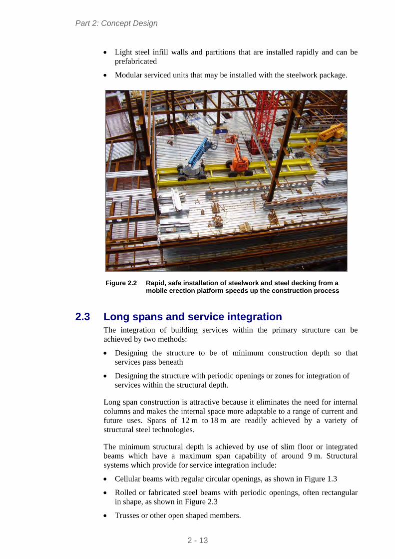
Part 2: Concept Design
Light steel infill walls and partitions that are installed rapidly and can be prefabricated
Modular serviced units that may be installed with the steelwork package.
Figure 2.2 Rapid, safe installation of steelwork and steel decking from a mobile erection platform speeds up the construction process
2.3 Long spans and service integration The integration of building services within the primary structure can be achieved by two methods:
Designing the structure to be of minimum construction depth so that services pass beneath
Designing the structure with periodic openings or zones for integration of services within the structural depth.
Long span construction is attractive because it eliminates the need for internal columns and makes the internal space more adaptable to a range of current and future uses. Spans of 12 m to 18 m are readily achieved by a variety of structural steel technologies.
The minimum structural depth is achieved by use of slim floor or integrated beams which have a maximum span capability of around 9 m. Structural systems which provide for service integration include:
Cellular beams with regular circular openings, as shown in Figure 1.3
Rolled or fabricated steel beams with periodic openings, often rectangular in shape, as shown in Figure 2.3
Trusses or other open shaped members.
2 - 13
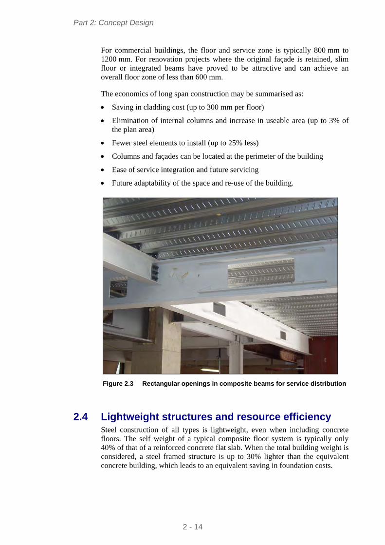
Part 2: Concept Design
For commercial buildings, the floor and service zone is typically 800 mm to 1200 mm. For renovation projects where the original façade is retained, slim floor or integrated beams have proved to be attractive and can achieve an overall floor zone of less than 600 mm.
The economics of long span construction may be summarised as:
Saving in cladding cost (up to 300 mm per floor)
Elimination of internal columns and increase in useable area (up to 3% of the plan area)
Fewer steel elements to install (up to 25% less)
Columns and façades can be located at the perimeter of the building
Ease of service integration and future servicing
Future adaptability of the space and re-use of the building.
Figure 2.3 Rectangular openings in composite beams for service distribution
2.4 Lightweight structures and resource efficiency Steel construction of all types is lightweight, even when including concrete floors. The self weight of a typical composite floor system is typically only 40% of that of a reinforced concrete flat slab. When the total building weight is considered, a steel framed structure is up to 30% lighter than the equivalent concrete building, which leads to an equivalent saving in foundation costs.
2 - 14
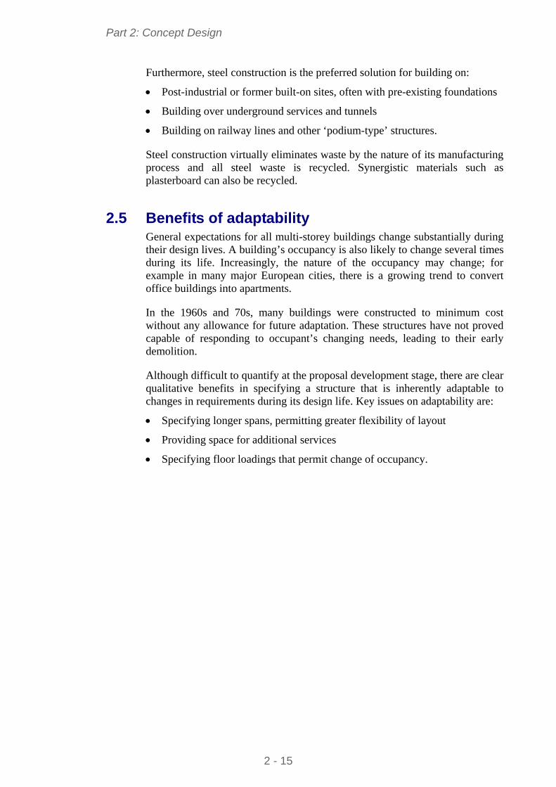
Part 2: Concept Design
Furthermore, steel construction is the preferred solution for building on:
Post-industrial or former built-on sites, often with pre-existing foundations
Building over underground services and tunnels
Building on railway lines and other ‘podium-type’ structures.
Steel construction virtually eliminates waste by the nature of its manufacturing process and all steel waste is recycled. Synergistic materials such as plasterboard can also be recycled.
2.5 Benefits of adaptability General expectations for all multi-storey buildings change substantially during their design lives. A building’s occupancy is also likely to change several times during its life. Increasingly, the nature of the occupancy may change; for example in many major European cities, there is a growing trend to convert office buildings into apartments.
In the 1960s and 70s, many buildings were constructed to minimum cost without any allowance for future adaptation. These structures have not proved capable of responding to occupant’s changing needs, leading to their early demolition.
Although difficult to quantify at the proposal development stage, there are clear qualitative benefits in specifying a structure that is inherently adaptable to changes in requirements during its design life. Key issues on adaptability are:
Specifying longer spans, permitting greater flexibility of layout
Providing space for additional services
Specifying floor loadings that permit change of occupancy.
2 - 15
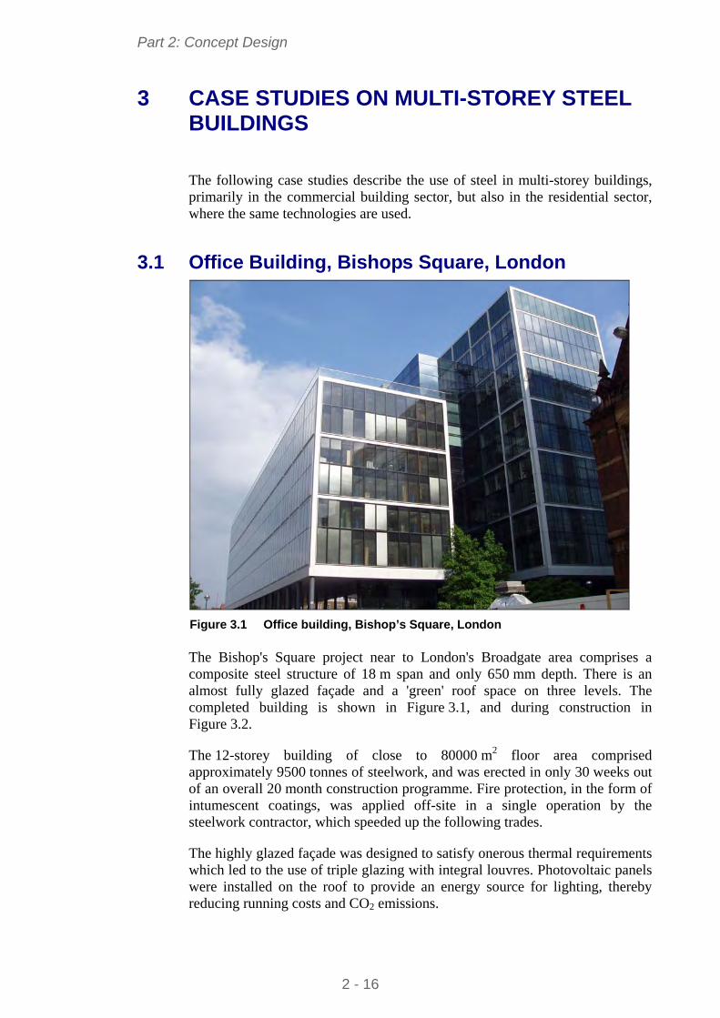
Part 2: Concept Design
3 CASE STUDIES ON MULTI-STOREY STEEL BUILDINGS
The following case studies describe the use of steel in multi-storey buildings, primarily in the commercial building sector, but also in the residential sector, where the same technologies are used.
3.1 Office Building, Bishops Square, London
Figure 3.1 Office building, Bishop’s Square, London
The Bishop's Square project near to London's Broadgate area comprises a composite steel structure of 18 m span and only 650 mm depth. There is an almost fully glazed façade and a 'green' roof space on three levels. The completed building is shown in Figure 3.1, and during construction in Figure 3.2.
The 12-storey building of close to 80000 m2 floor area comprised approximately 9500 tonnes of steelwork, and was erected in only 30 weeks out of an overall 20 month construction programme. Fire protection, in the form of intumescent coatings, was applied off-site in a single operation by the steelwork contractor, which speeded up the following trades.
The highly glazed façade was designed to satisfy onerous thermal requirements which led to the use of triple glazing with integral louvres. Photovoltaic panels were installed on the roof to provide an energy source for lighting, thereby reducing running costs and CO2 emissions.
2 - 16
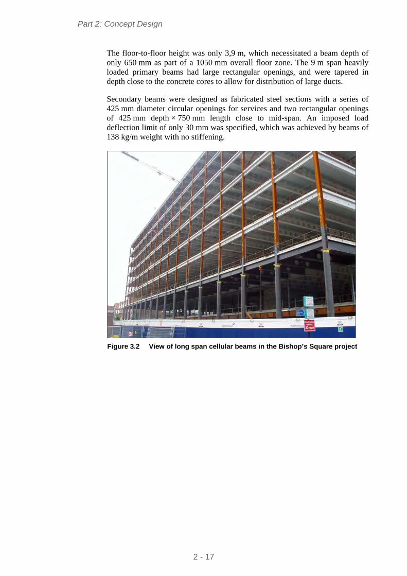
Part 2: Concept Design
The floor-to-floor height was only 3,9 m, which necessitated a beam depth of only 650 mm as part of a 1050 mm overall floor zone. The 9 m span heavily loaded primary beams had large rectangular openings, and were tapered in depth close to the concrete cores to allow for distribution of large ducts.
Secondary beams were designed as fabricated steel sections with a series of 425 mm diameter circular openings for services and two rectangular openings of 425 mm depth × 750 mm length close to mid-span. An imposed load deflection limit of only 30 mm was specified, which was achieved by beams of 138 kg/m weight with no stiffening.
Figure 3.2 View of long span cellular beams in the Bishop’s Square project
2 - 17
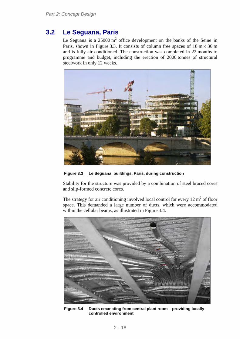
Part 2: Concept Design
3.2 Le Seguana, Paris Le Seguana is a 25000 m2 office development on the banks of the Seine in Paris, shown in Figure 3.3. It consists of column free spaces of 18 m 36 m and is fully air conditioned. The construction was completed in 22 months to programme and budget, including the erection of 2000 tonnes of structural steelwork in only 12 weeks.
Figure 3.3 Le Seguana buildings, Paris, during construction
Stability for the structure was provided by a combination of steel braced cores and slip-formed concrete cores.
The strategy for air conditioning involved local control for every 12 m2 of floor space. This demanded a large number of ducts, which were accommodated within the cellular beams, as illustrated in Figure 3.4.
Figure 3.4 Ducts emanating from central plant room – providing locally
controlled environment
2 - 18
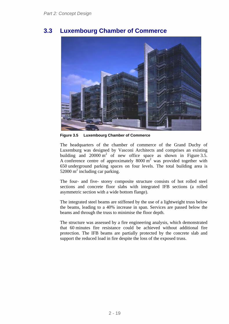
Part 2: Concept Design
3.3 Luxembourg Chamber of Commerce
Figure 3.5 Luxembourg Chamber of Commerce
The headquarters of the chamber of commerce of the Grand Duchy of Luxemburg was designed by Vasconi Architects and comprises an existing building and 20000 m2 of new office space as shown in Figure 3.5. A conference centre of approximately 8000 m2 was provided together with 650 underground parking spaces on four levels. The total building area is 52000 m2 including car parking.
The four- and five- storey composite structure consists of hot rolled steel sections and concrete floor slabs with integrated IFB sections (a rolled asymmetric section with a wide bottom flange).
The integrated steel beams are stiffened by the use of a lightweight truss below the beams, leading to a 40% increase in span. Services are passed below the beams and through the truss to minimise the floor depth.
The structure was assessed by a fire engineering analysis, which demonstrated that 60 minutes fire resistance could be achieved without additional fire protection. The IFB beams are partially protected by the concrete slab and support the reduced load in fire despite the loss of the exposed truss.
2 - 19
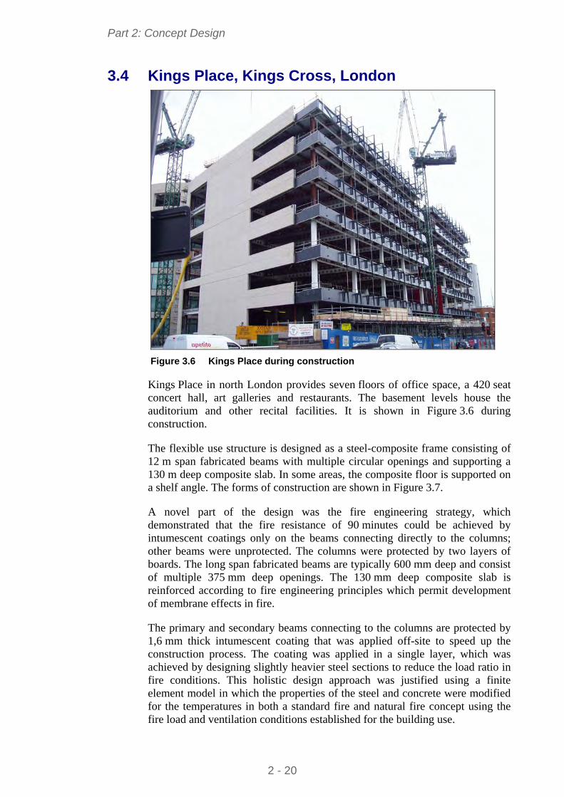
Part 2: Concept Design
3.4 Kings Place, Kings Cross, London
Figure 3.6 Kings Place during construction
Kings Place in north London provides seven floors of office space, a 420 seat concert hall, art galleries and restaurants. The basement levels house the auditorium and other recital facilities. It is shown in Figure 3.6 during construction.
The flexible use structure is designed as a steel-composite frame consisting of 12 m span fabricated beams with multiple circular openings and supporting a 130 m deep composite slab. In some areas, the composite floor is supported on a shelf angle. The forms of construction are shown in Figure 3.7.
A novel part of the design was the fire engineering strategy, which demonstrated that the fire resistance of 90 minutes could be achieved by intumescent coatings only on the beams connecting directly to the columns; other beams were unprotected. The columns were protected by two layers of boards. The long span fabricated beams are typically 600 mm deep and consist of multiple 375 mm deep openings. The 130 mm deep composite slab is reinforced according to fire engineering principles which permit development of membrane effects in fire.
The primary and secondary beams connecting to the columns are protected by 1,6 mm thick intumescent coating that was applied off-site to speed up the construction process. The coating was applied in a single layer, which was achieved by designing slightly heavier steel sections to reduce the load ratio in fire conditions. This holistic design approach was justified using a finite element model in which the properties of the steel and concrete were modified for the temperatures in both a standard fire and natural fire concept using the fire load and ventilation conditions established for the building use.
2 - 20
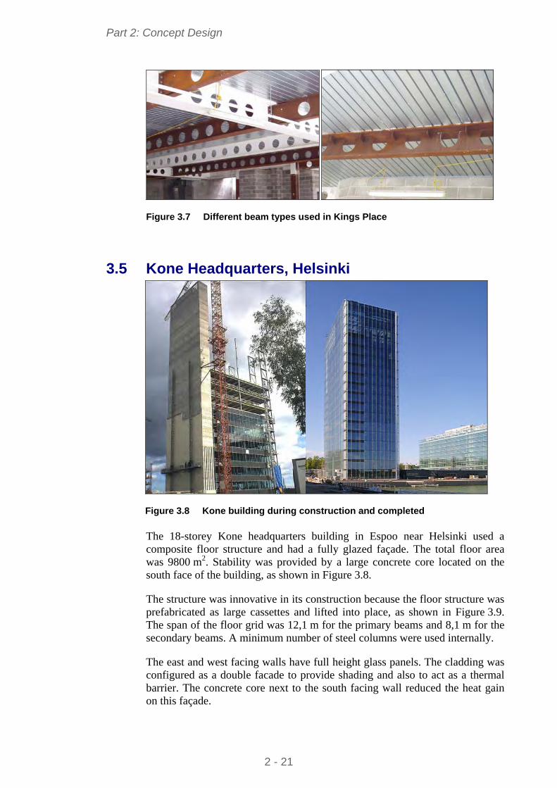
Part 2: Concept Design
Figure 3.7 Different beam types used in Kings Place
3.5 Kone Headquarters, Helsinki
Figure 3.8 Kone building during construction and completed
The 18-storey Kone headquarters building in Espoo near Helsinki used a composite floor structure and had a fully glazed façade. The total floor area was 9800 m2. Stability was provided by a large concrete core located on the south face of the building, as shown in Figure 3.8.
The structure was innovative in its construction because the floor structure was prefabricated as large cassettes and lifted into place, as shown in Figure 3.9. The span of the floor grid was 12,1 m for the primary beams and 8,1 m for the secondary beams. A minimum number of steel columns were used internally.
The east and west facing walls have full height glass panels. The cladding was configured as a double facade to provide shading and also to act as a thermal barrier. The concrete core next to the south facing wall reduced the heat gain on this façade.
2 - 21
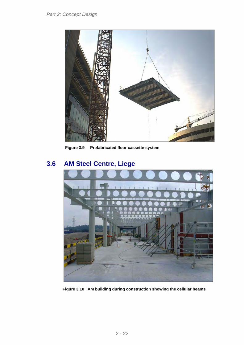
Part 2: Concept Design
Figure 3.9 Prefabricated floor cassette system
3.6 AM Steel Centre, Liege
Figure 3.10 AM building during construction showing the cellular beams
2 - 22
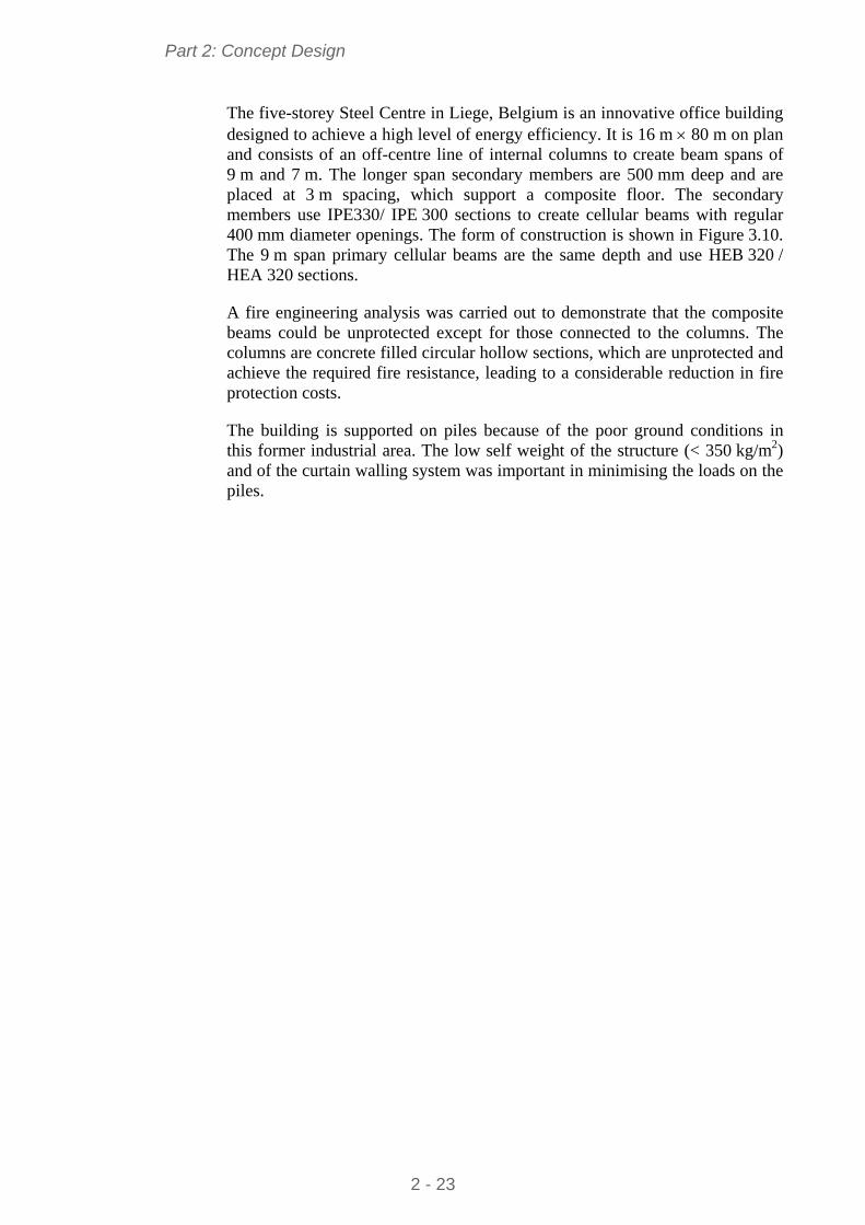
Part 2: Concept Design
The five-storey Steel Centre in Liege, Belgium is an innovative office building designed to achieve a high level of energy efficiency. It is 16 m 80 m on plan and consists of an off-centre line of internal columns to create beam spans of 9 m and 7 m. The longer span secondary members are 500 mm deep and are placed at 3 m spacing, which support a composite floor. The secondary members use IPE330/ IPE 300 sections to create cellular beams with regular 400 mm diameter openings. The form of construction is shown in Figure 3.10. The 9 m span primary cellular beams are the same depth and use HEB 320 / HEA 320 sections.
A fire engineering analysis was carried out to demonstrate that the composite beams could be unprotected except for those connected to the columns. The columns are concrete filled circular hollow sections, which are unprotected and achieve the required fire resistance, leading to a considerable reduction in fire protection costs.
The building is supported on piles because of the poor ground conditions in this former industrial area. The low self weight of the structure (< 350 kg/m2) and of the curtain walling system was important in minimising the loads on the piles.
2 - 23
Part 2: Concept Design
4 ANATOMY OF BUILDING DESIGN
The building design is dependent on various parameters:
Floor grid
Building height
Circulation and access space
Services requirements and service integration.
These aspects are addressed as follows:
4.1 Floor grids Floor grids define the spacing of the columns in orthogonal directions, which are influenced by:
The planning grid (normally based on units of 300 mm but more typically multiples of 0,6, 1,2 or 1,5 m)
The column spacing along the façade, depending on the façade material (typically 5,4 m to 7,5 m)
The use of the internal space (i.e. for offices or open plan space)
The requirements for building service distribution (from the building core).
Along the façade line, column spacings are normally defined by the need to provide support to the cladding system (for example, a maximum column spacing of 6 m is normally required for brickwork). This influences the column spacing internally, unless additional columns are used along the façade line.
The span of the beams across the building normally conforms to one of the following column grid arrangement:
Single internal line of columns, placed offset to the line of a central corridor. This is shown in Figure 4.1
Pairs of column lines on either side of a corridor
Column-free internal spans with columns located along the façade line.
For naturally ventilated offices, a building width of 12 m to 15 m is typically used, which can be achieved by two spans of 6 m to 7,5 m. A single span can also be provided with deep (400 mm or more) precast concrete hollow core units spanning the full width of the building. Natural lighting also plays a role in choice of the width of floor plate.
However, in modern buildings, a long span solution provides a considerable enhancement in flexibility of layout. For air-conditioned offices, a clear span of 15 m to 18 m is often used. An example of the column grid for a long span option in a building with a large atrium is shown in Figure 4.2.
2 - 24
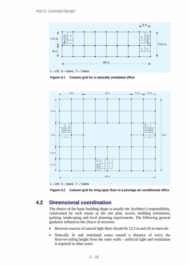
Part 2: Concept Design
7.5 m
6 m
6 m
48 m
13.5 m
T
L L
T
LS S
L – Lift; S – Stairs; T – Toilets Figure 4.1 Column grid for a naturally ventilated office
7.5 m7.5 m
7.5 m
7.5 m
15 m
15 m
30 m15 m
60 m
45 m
L
T
L
L
L
L
T
S S
L
S
L – Lift; S – Stairs; T – Toilets Figure 4.2 Column grid for long span floor in a prestige air conditioned office
4.2 Dimensional coordination The choice of the basic building shape is usually the Architect’s responsibility, constrained by such issues as the site plan, access, building orientation, parking, landscaping and local planning requirements. The following general guidance influences the choice of structure.
Between sources of natural light there should be 13,5 m and 20 m intervals
Naturally lit and ventilated zones extend a distance of twice the floor-to-ceiling height from the outer walls – artificial light and ventilation is required in other zones
2 - 25
Part 2: Concept Design
Atria improve the efficient use of the building, and reduce the running costs.
4.2.1 Influence of building height
The building height has a strong influence on the:
Structural system that is adopted
Foundation system
Fire resistance requirements and means of escape
Access (by lifts) and circulation space
Choice of cladding system
Speed of construction and site productivity.
For taller buildings, strategically placed concrete or braced steel cores are usually adopted. Ultra tall buildings are influenced strongly by the stabilising system, but are outside the scope of this guidance.
Sizes of lifts and their speed of movement also become important considerations for tall buildings.
Depending on the Regulations for fire safety in the particular country, the use of sprinklers may be required for buildings of more than eight storeys (or approximately 30 m high).
4.2.2 Horizontal coordination
Horizontal coordination is dominated by the need on plan for defined zones for vertical access, safe evacuation in fire, and vertical service distribution. Positioning of service and access cores is influenced by:
Horizontal distribution systems for mechanical services
Fire resistance requirements, which may control evacuation routes and compartment sizes
The need to distribute the stabilizing systems (bracing and cores) effectively throughout the building plan.
Figure 4.1 and Figure 4.2 show typical arrangements that satisfy these criteria.
An atrium may be incorporated to increase lighting to the occupied space and to provide high value circulation areas at ground and intermediate levels. The design requirements for atria are:
Support to the long span roof of the atrium
Access routes for general circulation
Fire safety measures by smoke extraction and safe evacuation routes
Light levels and servicing to internal offices.
2 - 26
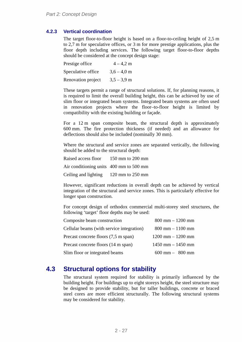
Part 2: Concept Design
4.2.3 Vertical coordination
The target floor-to-floor height is based on a floor-to-ceiling height of 2,5 m to 2,7 m for speculative offices, or 3 m for more prestige applications, plus the floor depth including services. The following target floor-to-floor depths should be considered at the concept design stage:
Prestige office 4 – 4,2 m
Speculative office 3,6 – 4,0 m
Renovation project 3,5 – 3,9 m
These targets permit a range of structural solutions. If, for planning reasons, it is required to limit the overall building height, this can be achieved by use of slim floor or integrated beam systems. Integrated beam systems are often used in renovation projects where the floor–to-floor height is limited by compatibility with the existing building or façade.
For a 12 m span composite beam, the structural depth is approximately 600 mm. The fire protection thickness (if needed) and an allowance for deflections should also be included (nominally 30 mm).
Where the structural and service zones are separated vertically, the following should be added to the structural depth:
Raised access floor 150 mm to 200 mm
Air conditioning units 400 mm to 500 mm
Ceiling and lighting 120 mm to 250 mm
However, significant reductions in overall depth can be achieved by vertical integration of the structural and service zones. This is particularly effective for longer span construction.
For concept design of orthodox commercial multi-storey steel structures, the following ‘target’ floor depths may be used:
Composite beam construction 800 mm – 1200 mm
Cellular beams (with service integration) 800 mm – 1100 mm
Precast concrete floors (7,5 m span) 1200 mm – 1200 mm
Precast concrete floors (14 m span) 1450 mm – 1450 mm
Slim floor or integrated beams 600 mm – 800 mm
4.3 Structural options for stability The structural system required for stability is primarily influenced by the building height. For buildings up to eight storeys height, the steel structure may be designed to provide stability, but for taller buildings, concrete or braced steel cores are more efficient structurally. The following structural systems may be considered for stability.
2 - 27
Part 2: Concept Design
4.3.1 Rigid frames
For buildings up to four storeys high, rigid frames may be used in which the multiple beam to column connections provide bending resistance and stiffness to resist horizontal loads. This is generally only possible where the beams are relatively deep (400 mm to 500 mm) and where the column size is increased to resist the applied moments. Full depth end plate connections generally provide the necessary rigidity.
4.3.2 Braced frames
For buildings up to 12 storeys high, braced steel frames are commonly used in which cross, K or V bracing is used in the walls, generally within a cavity in the façade, or around stairs or other serviced zones. Cross bracing is designed in tension only (the other member being redundant). Cross bracing is often simple flat steel plate, but angle sections and channel sections may also be used.
When bracing is designed to work in compression, hollow sections are often used, although angle sections and channel sections may also be used.
A steel braced frame has the two key advantages:
Responsibility for temporary stability lies with one organisation
As soon as the steel bracing is connected (bolted), the structure is stable.
4.3.3 Concrete or steel cores
Concrete cores are the most practical system for buildings of up to 40 storeys high, but the concrete core is generally constructed in advance of the steel framework. In this form of construction, the beams often span directly between the columns on the perimeter of the building and the concrete core. Special structural design considerations are required for:
The beam connections to the concrete core
The design of the heavier primary beams at the corner of core
Fire safety and robustness of the long span construction.
Special attention must be paid to the connections between the steel beams and the concrete cores allowing for adjustment, anticipating that the core may be out of position. The connection itself may not be completed until in situ concrete has cured, or until elements have been welded, so attention to temporary stability is important.
A typical layout of beams around a concrete core is shown in Figure 4.3, showing the use of heavier beams at the corner of the core. A double beam may be required to minimise the structural depth at the corner of the cores.
2 - 28
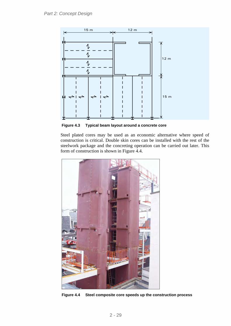
Part 2: Concept Design
12 m15 m
12 m
15 m
Figure 4.3 Typical beam layout around a concrete core
Steel plated cores may be used as an economic alternative where speed of construction is critical. Double skin cores can be installed with the rest of the steelwork package and the concreting operation can be carried out later. This form of construction is shown in Figure 4.4.
Figure 4.4 Steel composite core speeds up the construction process
2 - 29
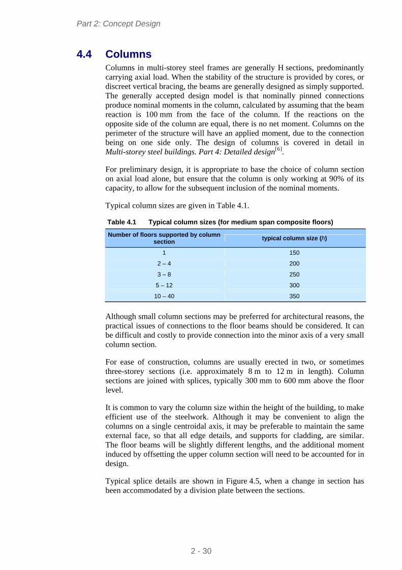
Part 2: Concept Design
4.4 Columns Columns in multi-storey steel frames are generally H sections, predominantly carrying axial load. When the stability of the structure is provided by cores, or discreet vertical bracing, the beams are generally designed as simply supported. The generally accepted design model is that nominally pinned connections produce nominal moments in the column, calculated by assuming that the beam reaction is 100 mm from the face of the column. If the reactions on the opposite side of the column are equal, there is no net moment. Columns on the perimeter of the structure will have an applied moment, due to the connection being on one side only. The design of columns is covered in detail in Multi-storey steel buildings. Part 4: Detailed design[6].
For preliminary design, it is appropriate to base the choice of column section on axial load alone, but ensure that the column is only working at 90% of its capacity, to allow for the subsequent inclusion of the nominal moments.
Typical column sizes are given in Table 4.1.
Table 4.1 Typical column sizes (for medium span composite floors)
Number of floors supported by column section
typical column size (h)
1 150
2 – 4 200
3 – 8 250
5 – 12 300
10 – 40 350
Although small column sections may be preferred for architectural reasons, the practical issues of connections to the floor beams should be considered. It can be difficult and costly to provide connection into the minor axis of a very small column section.
For ease of construction, columns are usually erected in two, or sometimes three-storey sections (i.e. approximately 8 m to 12 m in length). Column sections are joined with splices, typically 300 mm to 600 mm above the floor level.
It is common to vary the column size within the height of the building, to make efficient use of the steelwork. Although it may be convenient to align the columns on a single centroidal axis, it may be preferable to maintain the same external face, so that all edge details, and supports for cladding, are similar. The floor beams will be slightly different lengths, and the additional moment induced by offsetting the upper column section will need to be accounted for in design.
Typical splice details are shown in Figure 4.5, when a change in section has been accommodated by a division plate between the sections.
2 - 30
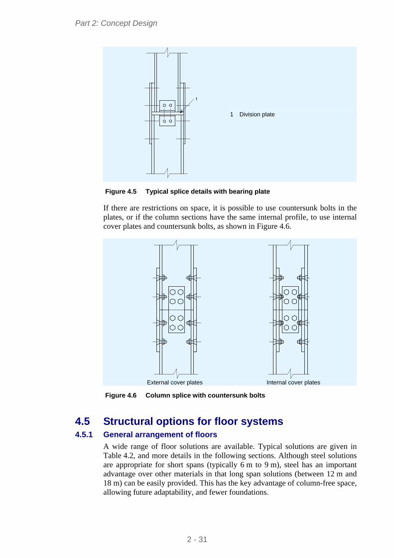
Part 2: Concept Design
1
1 Division plate
Figure 4.5 Typical splice details with bearing plate
If there are restrictions on space, it is possible to use countersunk bolts in the plates, or if the column sections have the same internal profile, to use internal cover plates and countersunk bolts, as shown in Figure 4.6.
External cover plates Internal cover plates
Figure 4.6 Column splice with countersunk bolts
4.5 Structural options for floor systems 4.5.1 General arrangement of floors
A wide range of floor solutions are available. Typical solutions are given in Table 4.2, and more details in the following sections. Although steel solutions are appropriate for short spans (typically 6 m to 9 m), steel has an important advantage over other materials in that long span solutions (between 12 m and 18 m) can be easily provided. This has the key advantage of column-free space, allowing future adaptability, and fewer foundations.
2 - 31
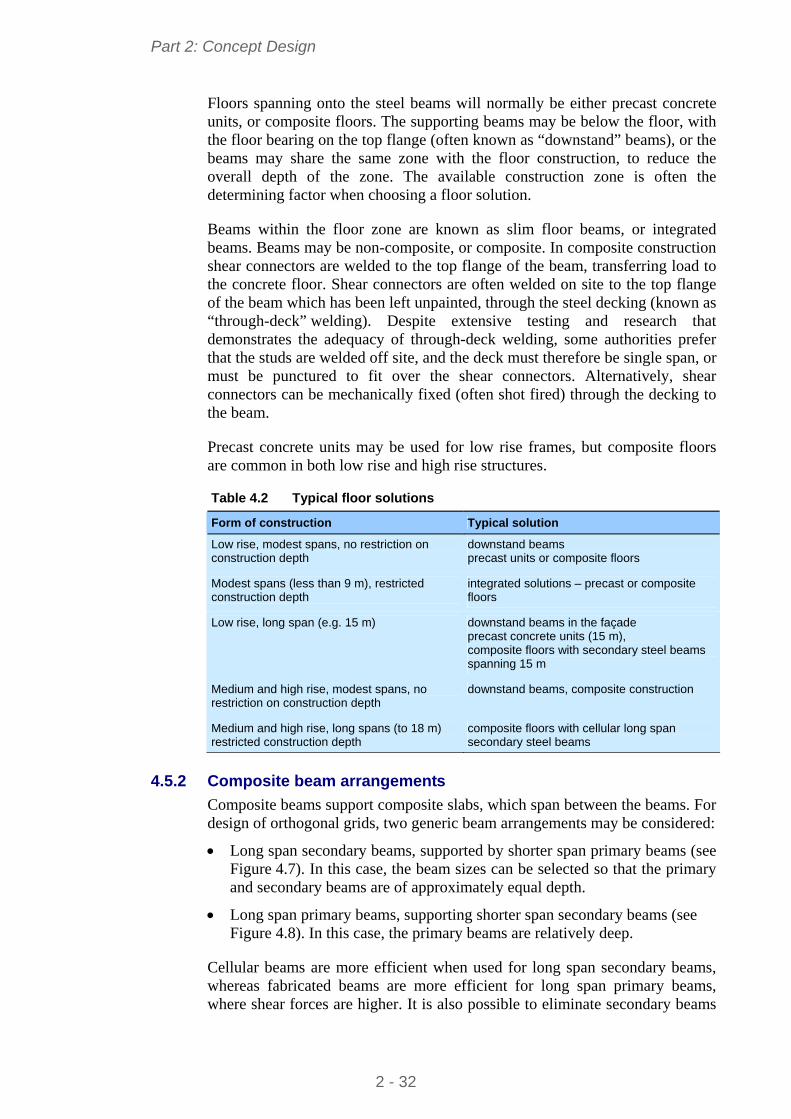
Part 2: Concept Design
Floors spanning onto the steel beams will normally be either precast concrete units, or composite floors. The supporting beams may be below the floor, with the floor bearing on the top flange (often known as “downstand” beams), or the beams may share the same zone with the floor construction, to reduce the overall depth of the zone. The available construction zone is often the determining factor when choosing a floor solution.
Beams within the floor zone are known as slim floor beams, or integrated beams. Beams may be non-composite, or composite. In composite construction shear connectors are welded to the top flange of the beam, transferring load to the concrete floor. Shear connectors are often welded on site to the top flange of the beam which has been left unpainted, through the steel decking (known as “through-deck” welding). Despite extensive testing and research that demonstrates the adequacy of through-deck welding, some authorities prefer that the studs are welded off site, and the deck must therefore be single span, or must be punctured to fit over the shear connectors. Alternatively, shear connectors can be mechanically fixed (often shot fired) through the decking to the beam.
Precast concrete units may be used for low rise frames, but composite floors are common in both low rise and high rise structures.
Table 4.2 Typical floor solutions
Form of construction Typical solution
Low rise, modest spans, no restriction on construction depth
downstand beams precast units or composite floors
Modest spans (less than 9 m), restricted construction depth
integrated solutions – precast or composite floors
Low rise, long span (e.g. 15 m) downstand beams in the façade precast concrete units (15 m), composite floors with secondary steel beams spanning 15 m
Medium and high rise, modest spans, no restriction on construction depth
downstand beams, composite construction
Medium and high rise, long spans (to 18 m) restricted construction depth
composite floors with cellular long span secondary steel beams
4.5.2 Composite beam arrangements
Composite beams support composite slabs, which span between the beams. For design of orthogonal grids, two generic beam arrangements may be considered:
Long span secondary beams, supported by shorter span primary beams (see Figure 4.7). In this case, the beam sizes can be selected so that the primary and secondary beams are of approximately equal depth.
Long span primary beams, supporting shorter span secondary beams (see Figure 4.8). In this case, the primary beams are relatively deep.
Cellular beams are more efficient when used for long span secondary beams, whereas fabricated beams are more efficient for long span primary beams, where shear forces are higher. It is also possible to eliminate secondary beams
2 - 32
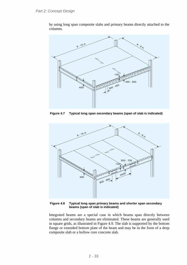
Part 2: Concept Design
by using long span composite slabs and primary beams directly attached to the columns.
130
450
450 - 600
300 - 450
9 - 15 m 6 - 9 m
Figure 4.7 Typical long span secondary beams (span of slab is indicated)
130
3002400
500 - 700
600 - 900
9 - 15 m 6 - 9 m
Figure 4.8 Typical long span primary beams and shorter span secondary
beams (span of slab is indicated)
Integrated beams are a special case in which beams span directly between columns and secondary beams are eliminated. These beams are generally used in square grids, as illustrated in Figure 4.9. The slab is supported by the bottom flange or extended bottom plate of the beam and may be in the form of a deep composite slab or a hollow core concrete slab.
2 - 33
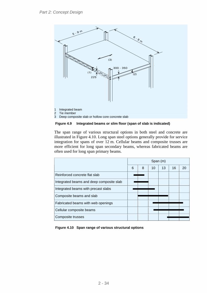
Part 2: Concept Design
225
300 - 350
5 - 9 m
6 - 9 m
(1)(2)
(3)
1 Integrated beam 2 Tie member 3 Deep composite slab or hollow core concrete slab Figure 4.9 Integrated beams or slim floor (span of slab is indicated)
The span range of various structural options in both steel and concrete are illustrated in Figure 4.10. Long span steel options generally provide for service integration for spans of over 12 m. Cellular beams and composite trusses are more efficient for long span secondary beams, whereas fabricated beams are often used for long span primary beams.
Span (m)
6 8 13 10 16 20
Reinforced concrete flat slab
Integrated beams and deep composite slab
Integrated beams with precast slabs
Composite beams and slab
Fabricated beams with web openings
Cellular composite beams
Composite trusses
Figure 4.10 Span range of various structural options
2 - 34
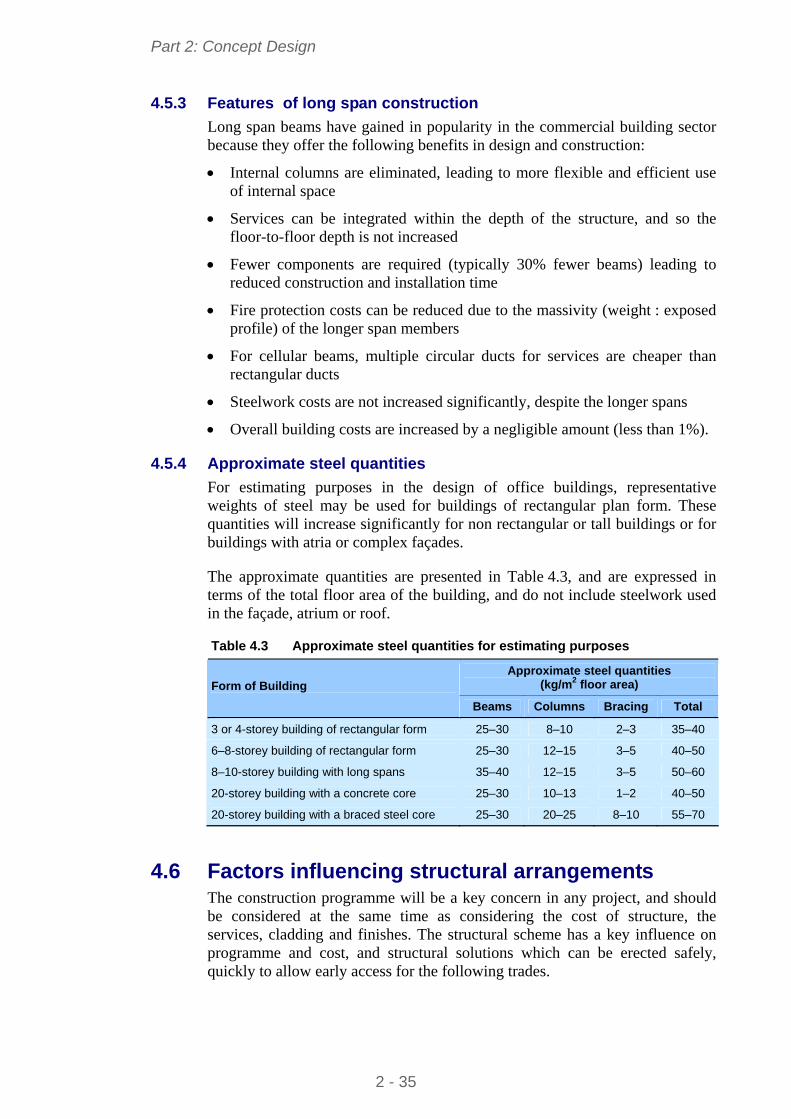
Part 2: Concept Design
4.5.3 Features of long span construction
Long span beams have gained in popularity in the commercial building sector because they offer the following benefits in design and construction:
Internal columns are eliminated, leading to more flexible and efficient use of internal space
Services can be integrated within the depth of the structure, and so the floor-to-floor depth is not increased
Fewer components are required (typically 30% fewer beams) leading to reduced construction and installation time
Fire protection costs can be reduced due to the massivity (weight : exposed profile) of the longer span members
For cellular beams, multiple circular ducts for services are cheaper than rectangular ducts
Steelwork costs are not increased significantly, despite the longer spans
Overall building costs are increased by a negligible amount (less than 1%).
4.5.4 Approximate steel quantities
For estimating purposes in the design of office buildings, representative weights of steel may be used for buildings of rectangular plan form. These quantities will increase significantly for non rectangular or tall buildings or for buildings with atria or complex façades.
The approximate quantities are presented in Table 4.3, and are expressed in terms of the total floor area of the building, and do not include steelwork used in the façade, atrium or roof.
Table 4.3 Approximate steel quantities for estimating purposes
Approximate steel quantities (kg/m2 floor area) Form of Building
Beams Columns Bracing Total
3 or 4-storey building of rectangular form 25–30 8–10 2–3 35–40
6–8-storey building of rectangular form 25–30 12–15 3–5 40–50
8–10-storey building with long spans 35–40 12–15 3–5 50–60
20-storey building with a concrete core 25–30 10–13 1–2 40–50
20-storey building with a braced steel core 25–30 20–25 8–10 55–70
4.6 Factors influencing structural arrangements The construction programme will be a key concern in any project, and should be considered at the same time as considering the cost of structure, the services, cladding and finishes. The structural scheme has a key influence on programme and cost, and structural solutions which can be erected safely, quickly to allow early access for the following trades.
2 - 35
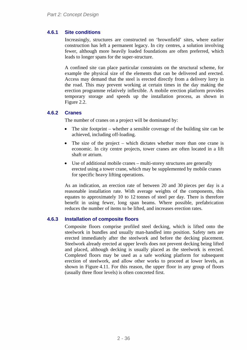
Part 2: Concept Design
4.6.1 Site conditions
Increasingly, structures are constructed on ‘brownfield’ sites, where earlier construction has left a permanent legacy. In city centres, a solution involving fewer, although more heavily loaded foundations are often preferred, which leads to longer spans for the super-structure.
A confined site can place particular constraints on the structural scheme, for example the physical size of the elements that can be delivered and erected. Access may demand that the steel is erected directly from a delivery lorry in the road. This may prevent working at certain times in the day making the erection programme relatively inflexible. A mobile erection platform provides temporary storage and speeds up the installation process, as shown in Figure 2.2.
4.6.2 Cranes
The number of cranes on a project will be dominated by:
The site footprint – whether a sensible coverage of the building site can be achieved, including off-loading.
The size of the project – which dictates whether more than one crane is economic. In city centre projects, tower cranes are often located in a lift shaft or atrium.
Use of additional mobile cranes – multi-storey structures are generally erected using a tower crane, which may be supplemented by mobile cranes for specific heavy lifting operations.
As an indication, an erection rate of between 20 and 30 pieces per day is a reasonable installation rate. With average weights of the components, this equates to approximately 10 to 12 tonnes of steel per day. There is therefore benefit in using fewer, long span beams. Where possible, prefabrication reduces the number of items to be lifted, and increases erection rates.
4.6.3 Installation of composite floors
Composite floors comprise profiled steel decking, which is lifted onto the steelwork in bundles and usually man-handled into position. Safety nets are erected immediately after the steelwork and before the decking placement. Steelwork already erected at upper levels does not prevent decking being lifted and placed, although decking is usually placed as the steelwork is erected. Completed floors may be used as a safe working platform for subsequent erection of steelwork, and allow other works to proceed at lower levels, as shown in Figure 4.11. For this reason, the upper floor in any group of floors (usually three floor levels) is often concreted first.
2 - 36
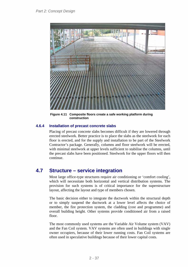
Part 2: Concept Design
Figure 4.11 Composite floors create a safe working platform during
construction
4.6.4 Installation of precast concrete slabs
Placing of precast concrete slabs becomes difficult if they are lowered through erected steelwork. Better practice is to place the slabs as the steelwork for each floor is erected, and for the supply and installation to be part of the Steelwork Contractor’s package. Generally, columns and floor steelwork will be erected, with minimal steelwork at upper levels sufficient to stabilise the columns, until the precast slabs have been positioned. Steelwork for the upper floors will then continue.
4.7 Structure – service integration Most large office-type structures require air conditioning or ‘comfort cooling’, which will necessitate both horizontal and vertical distribution systems. The provision for such systems is of critical importance for the superstructure layout, affecting the layout and type of members chosen.
The basic decision either to integrate the ductwork within the structural depth or to simply suspend the ductwork at a lower level affects the choice of member, the fire protection system, the cladding (cost and programme) and overall building height. Other systems provide conditioned air from a raised floor.
The most commonly used systems are the Variable Air Volume system (VAV) and the Fan Coil system. VAV systems are often used in buildings with single owner occupiers, because of their lower running costs. Fan Coil systems are often used in speculative buildings because of their lower capital costs.
2 - 37
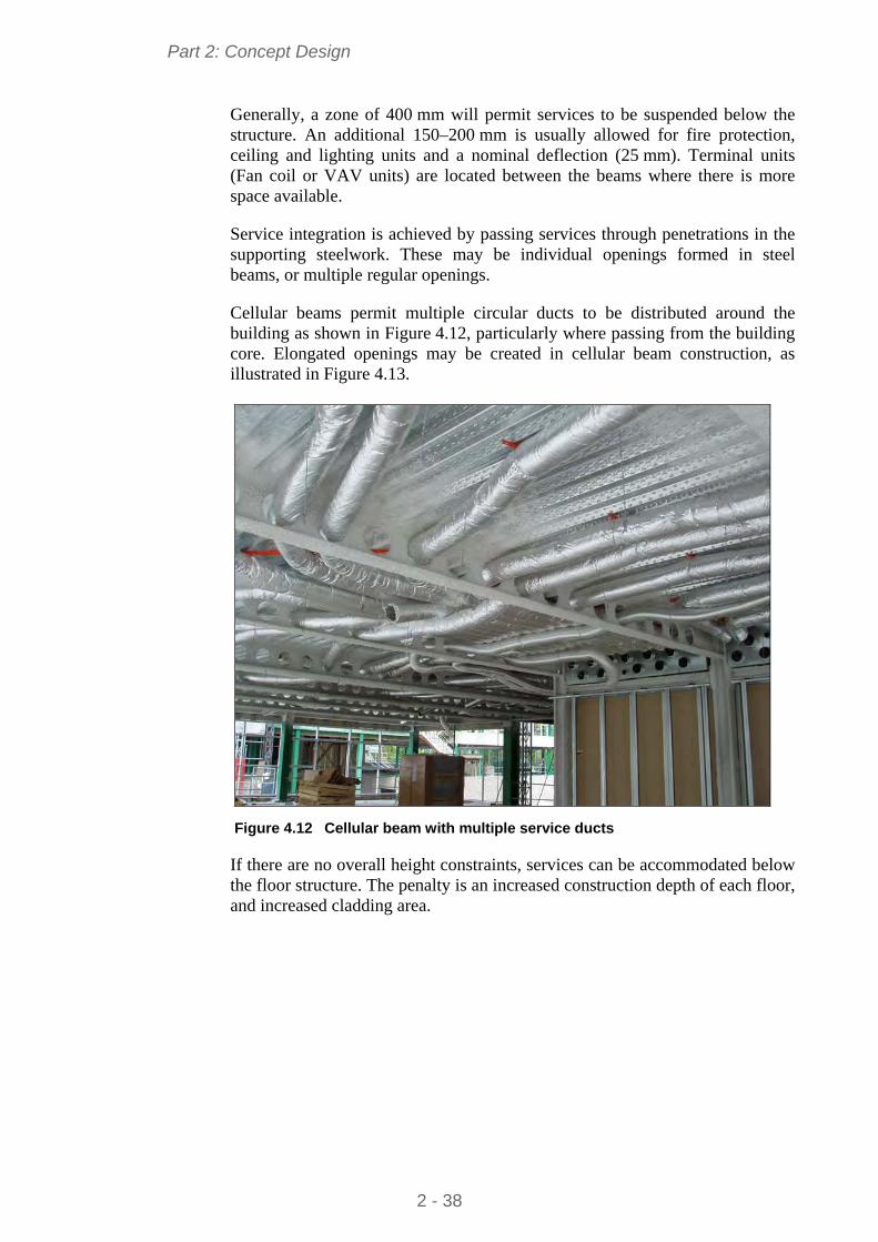
Part 2: Concept Design
Generally, a zone of 400 mm will permit services to be suspended below the structure. An additional 150–200 mm is usually allowed for fire protection, ceiling and lighting units and a nominal deflection (25 mm). Terminal units (Fan coil or VAV units) are located between the beams where there is more space available.
Service integration is achieved by passing services through penetrations in the supporting steelwork. These may be individual openings formed in steel beams, or multiple regular openings.
Cellular beams permit multiple circular ducts to be distributed around the building as shown in Figure 4.12, particularly where passing from the building core. Elongated openings may be created in cellular beam construction, as illustrated in Figure 4.13.
Figure 4.12 Cellular beam with multiple service ducts
If there are no overall height constraints, services can be accommodated below the floor structure. The penalty is an increased construction depth of each floor, and increased cladding area.
2 - 38
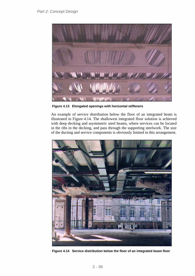
Part 2: Concept Design
Figure 4.13 Elongated openings with horizontal stiffeners
An example of service distribution below the floor of an integrated beam is illustrated in Figure 4.14. The shallowest integrated floor solution is achieved with deep decking and asymmetric steel beams, where services can be located in the ribs in the decking, and pass through the supporting steelwork. The size of the ducting and service components is obviously limited in this arrangement.
Figure 4.14 Service distribution below the floor of an integrated beam floor
2 - 39
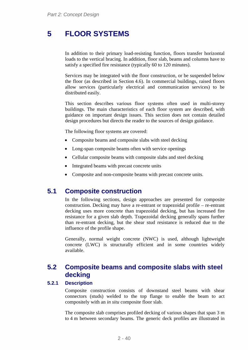
Part 2: Concept Design
5 FLOOR SYSTEMS
In addition to their primary load-resisting function, floors transfer horizontal loads to the vertical bracing. In addition, floor slab, beams and columns have to satisfy a specified fire resistance (typically 60 to 120 minutes).
Services may be integrated with the floor construction, or be suspended below the floor (as described in Section 4.6). In commercial buildings, raised floors allow services (particularly electrical and communication services) to be distributed easily.
This section describes various floor systems often used in multi-storey buildings. The main characteristics of each floor system are described, with guidance on important design issues. This section does not contain detailed design procedures but directs the reader to the sources of design guidance.
The following floor systems are covered:
Composite beams and composite slabs with steel decking
Long-span composite beams often with service openings
Cellular composite beams with composite slabs and steel decking
Integrated beams with precast concrete units
Composite and non-composite beams with precast concrete units.
5.1 Composite construction In the following sections, design approaches are presented for composite construction. Decking may have a re-entrant or trapezoidal profile – re-entrant decking uses more concrete than trapezoidal decking, but has increased fire resistance for a given slab depth. Trapezoidal decking generally spans further than re-entrant decking, but the shear stud resistance is reduced due to the influence of the profile shape.
Generally, normal weight concrete (NWC) is used, although lightweight concrete (LWC) is structurally efficient and in some countries widely available.
5.2 Composite beams and composite slabs with steel decking
5.2.1 Description
Composite construction consists of downstand steel beams with shear connectors (studs) welded to the top flange to enable the beam to act compositely with an in situ composite floor slab.
The composite slab comprises profiled decking of various shapes that span 3 m to 4 m between secondary beams. The generic deck profiles are illustrated in
2 - 40
Part 2: Concept Design
Figure 5.1 together with their typical slab depths. A ‘target’ slab depth of 130 mm is often used for 50 or 60 mm deep deck profiles, increasing to 150 mm for 80 mm deep deck profiles. Steel thicknesses of 0,8 mm to 1,2 mm are used depending on the deck spans.
The decking is normally designed to support the wet weight of the concrete and construction loading as a continuous member over two or three spans, but the composite slab is normally designed as simply supported between beams. Sufficient composite action occurs that it is generally the construction condition that controls the maximum spans that can be designed. Unpropped decking is preferred for reasons of speed of construction.
The secondary beams in the floor grid are supported by primary beams. These beams are usually designed as composite, but edge beams can be designed as non-composite, although shear connectors may be used for structural integrity and wind loads. A typical example of a composite beam used as an edge beam is shown in Figure 5.2.
110 - 130
130 - 150
140 - 170
Figure 5.1 Decking profiles used in composite construction
The shear connectors are normally site-welded through the decking to provide a secure fixing to the beam, and to enable the decking to provide restraint to the beam during the construction stage.
Mesh reinforcement, normally of 140 mm to 200 mm2/m cross-sectional area, is placed in the slab to enhance the fire resistance of the slab, to help distribute localised loads, to act as transverse reinforcement around the shear connectors and to reduce cracking in the slab over the beams.
2 - 41
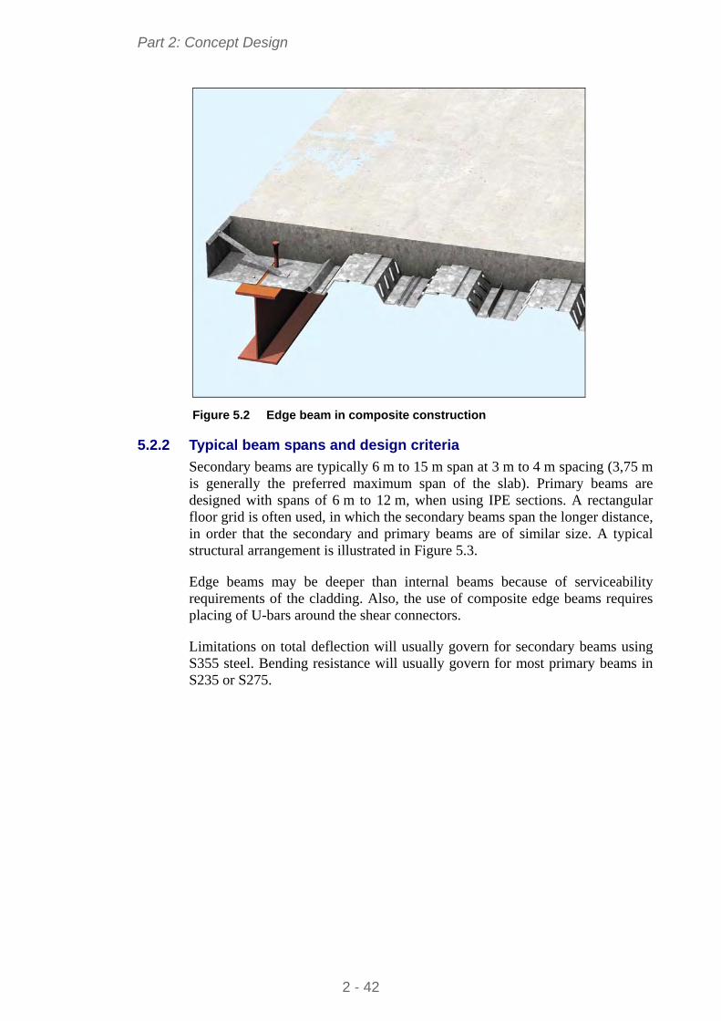
Part 2: Concept Design
Figure 5.2 Edge beam in composite construction
5.2.2 Typical beam spans and design criteria
Secondary beams are typically 6 m to 15 m span at 3 m to 4 m spacing (3,75 m is generally the preferred maximum span of the slab). Primary beams are designed with spans of 6 m to 12 m, when using IPE sections. A rectangular floor grid is often used, in which the secondary beams span the longer distance, in order that the secondary and primary beams are of similar size. A typical structural arrangement is illustrated in Figure 5.3.
Edge beams may be deeper than internal beams because of serviceability requirements of the cladding. Also, the use of composite edge beams requires placing of U-bars around the shear connectors.
Limitations on total deflection will usually govern for secondary beams using S355 steel. Bending resistance will usually govern for most primary beams in S235 or S275.
2 - 42
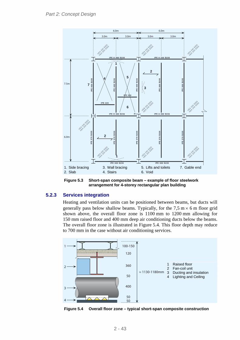
Part 2: Concept Design
6.0m 6.0m
3.0m 3.0m 3.0m 3.0m
7.5m
6.0m
1
1
4
7
5
6
3
2
2
IPE A 360 S235
IPE 220
IPE 220
IPE A 330 S235
IPE O 360 S235 P1 IPE A 360 S235
IPE 300 S235 IPE 300 S235
IPE
27
0 S
23
5
IPE
27
0 S
23
5
IPE
27
0 S
23
5
IPE
27
0 S
23
5
IPE
27
0 S
23
5
IPE
45
0 S
23
5
IPE
40
0 S
23
5
IPE
40
0 S
23
5
IPE
30
0 S
23
5
IPE
30
0 S
23
5
HEA 220 S
355
HEA 220 S
355
HEA 240 S
355
HEA 220 S
355
HEA 240 S
355
HEA 220 S
355
HEA 240 S
355
HEA 220 S
355
HEB 220 S
355
HEA 240 S
355
HEA 220 S
355
HEA 240 S
355
HEA 220 S
355
HEA 220 S
355
HEA 240 S
355
HEA 220 S
355
HEA 240 S
355
HEA 220 S
355
1. Side bracing 2. Slab
3. Wall bracing 4. Stairs
5. Lifts and toilets 6. Void
7. Gable end
Figure 5.3 Short-span composite beam – example of floor steelwork
arrangement for 4-storey rectangular plan building
5.2.3 Services integration
Heating and ventilation units can be positioned between beams, but ducts will generally pass below shallow beams. Typically, for the 7,5 m 6 m floor grid shown above, the overall floor zone is 1100 mm to 1200 mm allowing for 150 mm raised floor and 400 mm deep air conditioning ducts below the beams. The overall floor zone is illustrated in Figure 5.4. This floor depth may reduce to 700 mm in the case without air conditioning services.
100-150
120
360
50
5050
400
≈ 1130-1180mm
1
2
3
4
1 Raised floor 2 Fan-coil unit 3 Ducting and insulation 4 Lighting and Ceiling
Figure 5.4 Overall floor zone – typical short-span composite construction
2 - 43
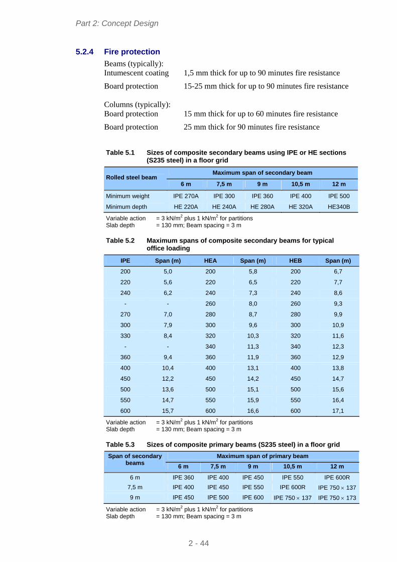
Part 2: Concept Design
5.2.4 Fire protection
Beams (typically): Intumescent coating 1,5 mm thick for up to 90 minutes fire resistance
Board protection 15-25 mm thick for up to 90 minutes fire resistance Columns (typically): Board protection 15 mm thick for up to 60 minutes fire resistance
Board protection 25 mm thick for 90 minutes fire resistance
Table 5.1 Sizes of composite secondary beams using IPE or HE sections (S235 steel) in a floor grid
Maximum span of secondary beam Rolled steel beam
6 m 7,5 m 10,5 m 9 m 12 m
Minimum weight IPE 270A IPE 300 IPE 360 IPE 400 IPE 500
Minimum depth HE 220A HE 240A HE 280A HE 320A HE340B
Variable action = 3 kN/m2 plus 1 kN/m2 for partitions Slab depth = 130 mm; Beam spacing = 3 m
Table 5.2 Maximum spans of composite secondary beams for typical office loading
IPE Span (m) HEA Span (m) HEB Span (m)
200 5,0 200 5,8 200 6,7
220 5,6 220 6,5 220 7,7
240 6,2 240 7,3 240 8,6
- - 260 8,0 260 9,3
270 7,0 280 8,7 280 9,9
300 7,9 300 9,6 300 10,9
330 8,4 320 10,3 320 11,6
- - 340 11,3 340 12,3
360 9,4 360 11,9 360 12,9
400 10,4 400 13,1 400 13,8
450 12,2 450 14,2 450 14,7
500 13,6 500 15,1 500 15,6
550 14,7 550 15,9 550 16,4
600 15,7 600 16,6 600 17,1
Variable action = 3 kN/m2 plus 1 kN/m2 for partitions Slab depth = 130 mm; Beam spacing = 3 m
Table 5.3 Sizes of composite primary beams (S235 steel) in a floor grid
Maximum span of primary beam Span of secondary beams
6 m 7,5 m 10,5 m 9 m 12 m
6 m IPE 360 IPE 400 IPE 450 IPE 550 IPE 600R
7,5 m IPE 400 IPE 450 IPE 550 IPE 600R IPE 750 137
9 m IPE 450 IPE 500 IPE 600 IPE 750 137 IPE 750 173
Variable action = 3 kN/m2 plus 1 kN/m2 for partitions Slab depth = 130 mm; Beam spacing = 3 m
2 - 44
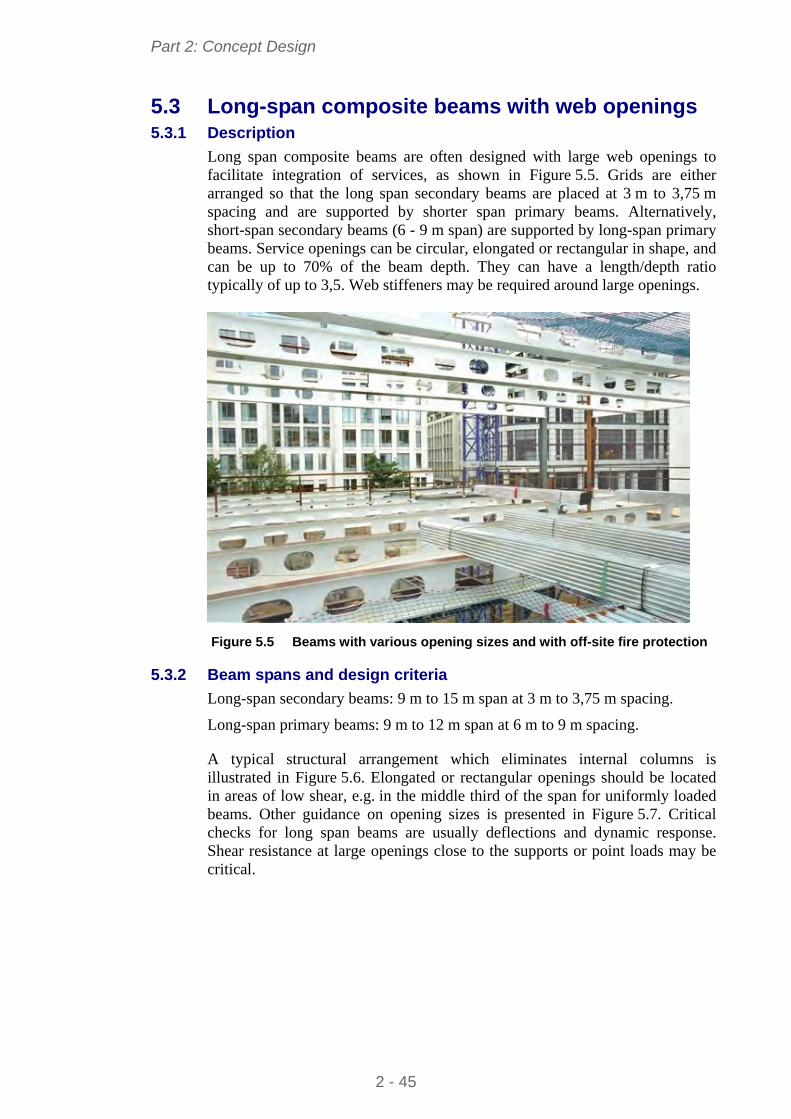
Part 2: Concept Design
5.3 Long-span composite beams with web openings 5.3.1 Description
Long span composite beams are often designed with large web openings to facilitate integration of services, as shown in Figure 5.5. Grids are either arranged so that the long span secondary beams are placed at 3 m to 3,75 m spacing and are supported by shorter span primary beams. Alternatively, short-span secondary beams (6 - 9 m span) are supported by long-span primary beams. Service openings can be circular, elongated or rectangular in shape, and can be up to 70% of the beam depth. They can have a length/depth ratio typically of up to 3,5. Web stiffeners may be required around large openings.
Figure 5.5 Beams with various opening sizes and with off-site fire protection
5.3.2 Beam spans and design criteria
Long-span secondary beams: 9 m to 15 m span at 3 m to 3,75 m spacing.
Long-span primary beams: 9 m to 12 m span at 6 m to 9 m spacing.
A typical structural arrangement which eliminates internal columns is illustrated in Figure 5.6. Elongated or rectangular openings should be located in areas of low shear, e.g. in the middle third of the span for uniformly loaded beams. Other guidance on opening sizes is presented in Figure 5.7. Critical checks for long span beams are usually deflections and dynamic response. Shear resistance at large openings close to the supports or point loads may be critical.
2 - 45
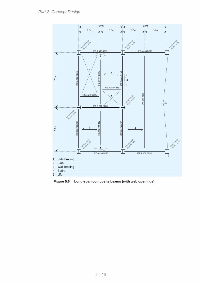
Part 2: Concept Design
6.0m
7.5m
6.0m
3.0m 3.0m
6.0m
3.0m 3.0m
1
1
3
42
5
2 2
IPE A 330 S235
IPE O 360 S235
IPE A 240 S235
IPE A 240 S235
IPE A 360 S235 IPE A 450 S235
IPE A 450 S235
IPE
A 5
00 S
235
IPE
O 4
00 S
235
IPE
O 4
00 S
235
IPE
O 2
70 S
235
IPE
O 2
70 S
235
IPE
O 2
70 S
235
IPE
550
S23
5
HE 220 A
S35
5
HE 220 A
S35
5
HE 240 A
S35
5
HE 220 A
S35
5
HE 240 A
S35
5
HE 220 A
S35
5
HE 220 A
S35
5
HE 220 A
S35
5
HE 280 A
S35
5
HE 220 A
S35
5
HE 280 A
S35
5
HE 240 A
S35
5
HE 280 A
S35
5
HE 220 A
S35
5
HE 280 A
S35
5
HE 240 A
S35
5
1. Side bracing 2. Slab 3. Wall bracing 4. Stairs 5. Lift Figure 5.6 Long-span composite beams (with web openings)
2 - 46
Part 2: Concept Design
h
h
l
l ll
0
0 00 0
0.25h
h h
0
0
0.7h
hh
h h
0.5 0 0.4 0
0.8
2.5
Figure 5.7 Limits of sizes and spacing of circular and rectangular web
openings
5.3.3 Services integration
Service ducts may pass through openings in the web of the beams. Ducts for air conditioning are approximately 400 mm deep, but vary between manufacturers. Larger service units, which are typically 450 mm deep, but up to 750 mm for variable air volume (VAV) units can be situated between beams. The overall depth of the floor zone will be typically:
1000 mm for 13,5 m span beam (with 300 mm deep web openings)
1200 mm for 15 m span beams (with 400 mm deep web openings)
5.3.4 Fire protection
Fire protection may be in the form of board protection or intumescent coating (intumescent coatings can be applied off-site as a single coating up to 1,8 mm thick in order to achieve 90 minutes fire resistance), as illustrated in Figure 5.5.
5.4 Cellular composite beams with composite slab and steel decking
5.4.1 Description
Cellular beams are beams with circular openings with regular spacing along their length, as illustrated in Figure 5.8. The beams are made by cutting and re-welding hot rolled steel sections. Openings, or ‘cells’, are normally circular, which are ideally suited to circular ducts, but can be elongated, rectangular or hexagonal. Cells may have to be filled in to create a solid web at positions of high shear, such as at supports or either side of point loads along the beam.
2 - 47
Part 2: Concept Design
The size and spacing of the openings can be restricted by the fabrication method. However, the full range of section sizes is available from which to chose the sizes of the top and bottom chords. For composite design, the top chord is generally chosen as a lighter section than the bottom chord
Cellular beams can be arranged as long-span secondary beams, supporting the floor slab directly, or in some cases, as long-span primary beams supporting other cellular beams or I section secondary beams.
Figure 5.8 Long-span secondary cellular beams with regular circular
openings
5.4.2 Beam spans and design criteria
Secondary beams should be spaced at 3 m to 3,75 m to avoid temporary propping of the decking during construction. Opening sizes are typically 60 to 80% of the beam depth. Stiffeners may be required for elongated openings. Large (elongated or rectangular) openings should be located in areas of low shear, e.g. in the middle third of span for uniformly loaded beams.
A structural arrangement for corner of a floor around an atrium is illustrated in Figure 5.9. In this case, the floor grid is 15 m 7,5 m, in which the cellular beams are 15 m span and 670 mm deep. Internal beams are eliminated except around the service cores.
Shear or buckling of the web posts may occur between openings, particularly near high point loads or adjacent to elongated openings. In this case, the spacing of the openings should be increased or heavier sections used. Typical chord sizes for 12 m to 18 m span cellular secondary beams at 3 m spacing are presented in Table 5.4.
2 - 48
Part 2: Concept Design
Table 5.4 Sizes of composite cellular beams as secondary beams (IPE/HE sections in S355 steel)
Maximum span of cellular beam (m) Cellular beam parameters
12 m 13,5 m 16,5 m 15 m 18 m
Opening diameter (mm) 300 350 400 450 500
Beam depth (mm) 460 525 570 630 675
Top chord IPE 360 IPE 400 IPE 400 IPE 450 IPE 500
Bottom chord HE 260A HE 300A HE 340B HE 360B HE 400M
Variable action = 3 kN/m2 plus 1 kN/m2 for partitions Slab depth = 130 mm; Beam spacing = 3 m
15.0m
3.75m
7.5m
7.5m
3.0m
3.0m
4.5m
3.0m
1.5m
3.75m 3.75m 3.75m 3.75m 3.75m 3.75m 3.75m
15.0m
IPE 450 S355
HEB 320 S355
IPE O 400 S235
IPE A 360 S355
IPE O 400 S235
IPE A 360 S355
HEB 320 S355
HEB 300 S355
HEB 300 S355
IPE O 300 S235
IPE O 300 S235
IPE O 300 S235
HEB 450 S355 HEB 450 S355
IPE
O 3
60
S2
35
IPE
O 3
60
S2
35
IPE
A 4
50
/ I
PE
A 5
50
S3
55
IPE
A 4
50
/ I
PE
A 5
50
S3
55
IPE
A 4
50
/ I
PE
A 5
50
S3
55
IPE
A 4
50
/ I
PE
A 5
50
S3
55
IPE
A 4
50
/ I
PE
A 5
50
S3
55
IPE
A 4
50
/ I
PE
A 5
50
S3
55
IPE
A 4
50
/ I
PE
A 5
50
S3
55
IPE
A 4
50
/ I
PE
A 5
50
S3
55
IPE
O 3
60
S2
35 IP
E 2
20
S2
35
IPE
22
0S
23
5
IPE
22
0S
23
5
IPE
22
0S
23
5
IPE
O 3
60
S2
35
IPE
A 3
60
S2
35
IPE
A 3
60
S2
35
HE
B 3
00
S3
55
HE
B 3
00
S3
55
IPE 450 S355 IPE 450 S355 IPE 450 S355
76.1 x 3.2
CHS S275
76.1 x 3.2
CHS S275
76.1
x 3
.2
CHS S27
5
76.1
x 3
.2
CHS S27
5
2
1
3
5
4
46 6
1. Wall bracing 2. Slab 3. Toilets 4. Void 5. Stairs 6. Lifts Figure 5.9 Cellular beams (long-span secondary beams) – example of
steelwork arrangement at the corner of a 8-storey building with an atrium
2 - 49
Part 2: Concept Design
5.4.3 Services integration
Regular openings in the web allow ducts to pass through the beams as shown in Figure 5.10. Larger services equipment is located between the beams. Opening sizes should allow for any insulation around the services. Fabrication should be arranged to ensure web openings align through the beams along the building.
The overall floor zone can be as low as 1000 mm for 15 m span beams with regular 400 mm openings, which is much shallower than the case where ducts pass below the beams.
150
140
600
100
50
≈1050
1
2
3
1 Raised floor 2 Ducting and insulation
400 diameter 3 Lighting and Ceiling
Figure 5.10 Cellular beam – Typical cross-section showing services
integration
5.4.4 Fire protection
Intumescent coatings are the preferred fire protection system for cellular beams, and are often applied off-site. Reference 7 gives advice on fire protection of beams with web openings.
5.5 Composite beams with precast concrete units 5.5.1 Description
This system consists of steel beams with shear connectors that are often pre-welded to the top flange as part of the fabrication process. The beams support precast concrete units with a structural concrete infill over the beam between the ends of the units, and often with an additional topping covering the units. The precast concrete (P.C.) units are either hollow core, normally 150 - 260 mm deep, or solid planks of 75 mm to 100 mm depth.
At the supports, deeper P.C. units are either chamfered on their upper face or notched so that the in situ concrete fully encases the shear connectors. Narrow openings are created within the hollow core units during the manufacturing process to allow transverse reinforcement to be placed across the beams and embedded in the precast units for approximately 600 mm on either side, as shown in Figure 5.11.
2 - 50
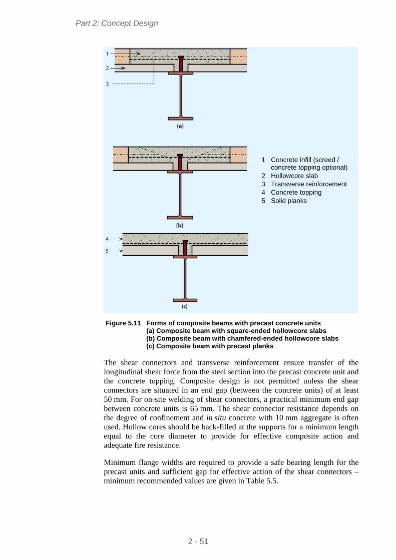
Part 2: Concept Design
(a)
1
2
3
(b)
(c)
4
5
1 Concrete infill (screed / concrete topping optional)
2 Hollowcore slab 3 Transverse reinforcement 4 Concrete topping 5 Solid planks
Figure 5.11 Forms of composite beams with precast concrete units
(a) Composite beam with square-ended hollowcore slabs (b) Composite beam with chamfered-ended hollowcore slabs (c) Composite beam with precast planks
The shear connectors and transverse reinforcement ensure transfer of the longitudinal shear force from the steel section into the precast concrete unit and the concrete topping. Composite design is not permitted unless the shear connectors are situated in an end gap (between the concrete units) of at least 50 mm. For on-site welding of shear connectors, a practical minimum end gap between concrete units is 65 mm. The shear connector resistance depends on the degree of confinement and in situ concrete with 10 mm aggregate is often used. Hollow cores should be back-filled at the supports for a minimum length equal to the core diameter to provide for effective composite action and adequate fire resistance.
Minimum flange widths are required to provide a safe bearing length for the precast units and sufficient gap for effective action of the shear connectors – minimum recommended values are given in Table 5.5.
2 - 51
Part 2: Concept Design
Table 5.5 Minimum widths for bearing of PC units
Minimum beam width
Internal beam 180 mm 75 mm or 100 mm deep solid precast unit
Edge beam 210 mm
Internal beam 180 mm Hollow core precast unit
Edge beam 210 mm
Non-composite edge beam 120 mm
Edge beams are often designed as non-composite, with nominal shear connection provided to meet robustness and stability requirements. These shear connectors are usually site-welded through openings cast in the precast units. Composite edge beams require careful detailing of U-bar reinforcement into slots in the precast concrete units, and a greater minimum flange width.
Temporary bracing providing lateral restraint is often required to reduce the effective length for lateral torsional buckling of the beam during the construction stage, when only one side is loaded. Full torsional restraint in the temporary condition may be difficult to achieve, unless deep restraint members with rigid connections are used, or by developing ‘U-frame action’ involving the beams, the restraint members and rigid connections.
5.5.2 Beam span and design criteria
Long span secondary beams should provide sufficient minimum width to support the P.C. units as given in Table 5.5, so an IPE 400 mm is the minimum practical beam depth. Beams that are placed parallel to the span of the precast units cannot usually be designed compositely.
Edge beams are generally designed as non-composite, but are tied into the floor to meet robustness requirements.
Transverse reinforcement must be provided in all composite design cases, as shown in Figure 5.11 and Figure 5.12.
The critical check is often torsional resistance and twist, or combined torsion and lateral torsional buckling resistance in the construction condition (with loads on one side only).
2 - 52
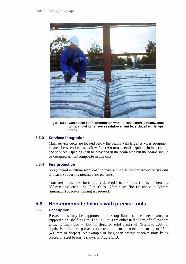
Part 2: Concept Design
Figure 5.12 Composite floor construction with precast concrete hollow core
units, showing transverse reinforcement bars placed within open cores
5.5.3 Services integration
Main service ducts are located below the beams with larger services equipment located between beams. Allow for 1200 mm overall depth including ceiling and services. Openings can be provided in the beam web but the beams should be designed as non-composite in this case.
5.5.4 Fire protection
Spray, board or intumescent coating may be used as the fire protection systems to beams supporting precast concrete units.
Transverse bars must be carefully detailed into the precast units – extending 600 mm into each unit. For 90 to 120 minutes fire resistance, a 50 mm (minimum) concrete topping is required.
5.6 Non-composite beams with precast units 5.6.1 Description
Precast units may be supported on the top flange of the steel beams, or supported on ‘shelf’ angles. The P.C. units are either in the form of hollow core units, normally 150 – 400 mm deep, or solid planks of 75 mm to 100 mm depth. Hollow core precast concrete units can be used to span up to 15 m (400 mm or deeper). An example of long span precast concrete units being placed on steel beams is shown in Figure 5.13.
2 - 53
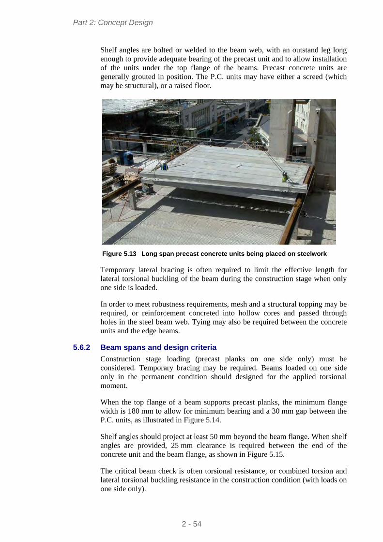
Part 2: Concept Design
Shelf angles are bolted or welded to the beam web, with an outstand leg long enough to provide adequate bearing of the precast unit and to allow installation of the units under the top flange of the beams. Precast concrete units are generally grouted in position. The P.C. units may have either a screed (which may be structural), or a raised floor.
Figure 5.13 Long span precast concrete units being placed on steelwork
Temporary lateral bracing is often required to limit the effective length for lateral torsional buckling of the beam during the construction stage when only one side is loaded.
In order to meet robustness requirements, mesh and a structural topping may be required, or reinforcement concreted into hollow cores and passed through holes in the steel beam web. Tying may also be required between the concrete units and the edge beams.
5.6.2 Beam spans and design criteria
Construction stage loading (precast planks on one side only) must be considered. Temporary bracing may be required. Beams loaded on one side only in the permanent condition should designed for the applied torsional moment.
When the top flange of a beam supports precast planks, the minimum flange width is 180 mm to allow for minimum bearing and a 30 mm gap between the P.C. units, as illustrated in Figure 5.14.
Shelf angles should project at least 50 mm beyond the beam flange. When shelf angles are provided, 25 mm clearance is required between the end of the concrete unit and the beam flange, as shown in Figure 5.15.
The critical beam check is often torsional resistance, or combined torsion and lateral torsional buckling resistance in the construction condition (with loads on one side only).
2 - 54
Part 2: Concept Design
5.6.3 Services integration
Main service ducts are located below the beams with larger services equipment located between beams.
180 min.
30
75 min.
50
50 min.
75 min.
(a) Units sitting on downstand beam (b) Units sitting on shelf angle beam Figure 5.14 Floor construction with precast concrete units in non-composite
construction
25 min.
Figure 5.15 Bearing and clearance requirements for precast units on shelf
angle beams
5.6.4 Fire protection
Fire protection may be spray, board or an intumescent coating to the beam. Shelf angle beams can achieve 30 minutes fire resistance by up-turning the angles, (the vertical leg is above the projecting leg, as shown in Figure 5.15) so that they remain relatively cool in fire.
5.7 Integrated beams with precast concrete units 5.7.1 Description
Precast concrete units may be used as part of a slim floor or integrated beam system, in which the beams are contained within the floor depth, as illustrated in Figure 5.16. Two forms of steel beams are commonly used:
A steel plate (typically 15 mm thick) may welded to the underside of an H section. This plate extends beyond the bottom flange by at least 100 mm either side, in order to support the precast concrete units.
A 20 mm flange plate (typical) may be welded to half of an I section cut along the web.
2 - 55
Part 2: Concept Design
A structural concrete topping with reinforcement is recommended in order to tie the P.C. units together. The topping thickness should cover the P.C. units by at least 50 mm. If used without a topping, reinforcement should be provided through the web of the beam to tie the floor on each side of the beam together in order to meet robustness requirements.
1 Hollowcore concrete slab
2 IFB/SFB – beam 3 Column section
Figure 5.16 Integrated floor beam (slim floor beam) and precast concrete units
A composite integrated beam can be achieved by welding shear connectors (normally 19 mm diameter 70 mm long) to the top flange of the steel section. Reinforcement is then placed across the flange into slots prepared in the precast units, or on top of shallow precast units. If the beams are designed compositely, the topping should cover the shear connectors by at least 15 mm, and the precast units by at least 60 mm.
A typical structural arrangement in which the integrated beams span 6 m and the P.C. units span 7,5 m is illustrated in Figure 5.17. In this case, the P.C. units are 200 mm deep and a 60 mm concrete topping is used. The edge beams are IPE, designed as non-composite and are placed below the P.C. units. Nominal shear connectors are provided to meet robustness requirements. In this case, the slab can be cast level with the top of the beam, as shown in Figure 5.18.
5.7.2 Beam spans and design criteria
Ideally, the span of the precast concrete units and the beam span should be optimised to produce a floor thickness compatible with the beam depth. Beams loaded on one side only are relatively heavy because of their torsional loading. Also, torsional effects during construction will need to be checked. A central spine beam with precast units spanning to downstand edge beams (beams located under the P.C. units, but concealed in the wall) will generally be more economic than the P.C. units spanning along the building, onto a series of transverse spanning beams.
Composite edge beams require careful detailing of U-bars around the shear connectors and into the precast units or structural topping – therefore non-composite edge beams are preferred.
2 - 56
Part 2: Concept Design
Critical checks are usually the torsional resistance, combined torsion and lateral torsional buckling resistance in the construction condition (when loaded on one side only), or lateral torsional buckling in the construction condition (with loads on both sides). Deflection may be critical for all types of integrated beams.
Typical beam sizes of slim floor beams and integrated beams for spans of 5 m to 8 m are presented in Table 5.6 and Table 5.7 respectively.
6.0m
3.0m 3.0m
6.0m
6.0m
7.5m
HEA 220 S
355
HEA 220 S
355
HEA 240 S
355
HEA 220 S
355
HEA 240 S
355
HEA 220 S
355
HEB 220 S
355
HEA 240 S
355
HEA 240 S
355
HEA 220 S
355
HEB 220 S
355
HEA 240 S
355
HEA 240 S
355
HEA 220 S
355
HEA 220 S
355
HEA 220 S
355
HEA 240 S
355
HEA 220 S
355
IPE 400 S235
IPE
A 4
50 S
235
IPE
400
S23
5
IPE
400
S23
5
IPE
240
S23
5IP
E 2
40 S
235
IPE
240
S23
5
IPE
O 3
00 S
235
IPE 400 S235
IPE A 400 S235
6HEB 260/460 x 15
IPE A 400 S235
6HEB 260/460 x 15
IPE 220 S235
IPE 220 S235
1
2
1
345
1. Side bracing 2. Precast concrete units + 60 mm NWC topping 3. Wall bracing 4. Stairs 5. Lifts and toilets 6. Slimflor beam Figure 5.17 Slim floor steelwork arrangement for a four-storey rectangular
building (central spine slim floor beam and downstand edge beams)
2 - 57
Part 2: Concept Design
5.7.3 Services integration
The flat floor soffit allows unrestricted access for services below the floor, as shown in Figure 5.18.
1
3
2
60
200
5
4
1 NWC topping 2 A142 mesh
3 T12 1200 long tie bars @ 600 ctrs through holes in web
4 HEB 260
5 460 15 plate
Figure 5.18 Slim floor construction – typical cross-section using precast units
5.7.4 Fire protection
The concrete encasement around the beam is normally sufficient to provide up to 60 minutes fire resistance without additional protection.
For 90 minutes fire resistance, an intumescent coating or board protection to the flange plate is required. Correct detailing of transverse reinforcement is required, particularly for hollow core units, where filling of the cores adjacent to the beam is necessary.
Table 5.6 Span of slim floor beams comprising HE sections and welded bottom plate
Typical beam size for slim floor beam span Span of slab (m)
5 m 6 m 7 m 8 m
5 HE 200A HE 240A HE 280A HE 300A
6 HE 240A HE 280A HE 300A HE 280A
7 HE 280A HE 300A HE 280B HE 300B
8 HE 280A HE 280B HE 300B HE 320B
Slab depth equal to the beam depth, plus 50 mm The welded plate should be 150 mm wider than the HE section
Table 5.7 Span of integrated beams cut from IPE sections with a welded bottom flange plate
Typical beam size for integrated beam span Span of slab (m)
5 m 6 m 7 m 8 m
5 IPE 400 IPE 500 IPE 550 IPE 600
6 IPE 500 IPE 550 IPE 600 HE 500A
7 IPE 550 IPE 600 HE 500A HE 600A
8 IPE 600 HE 500A HE 600A HE 600B
All section sizes are cut to be half the IPE section sizes given A 20 mm thick welded bottom flange plate is used in all cases
2 - 58
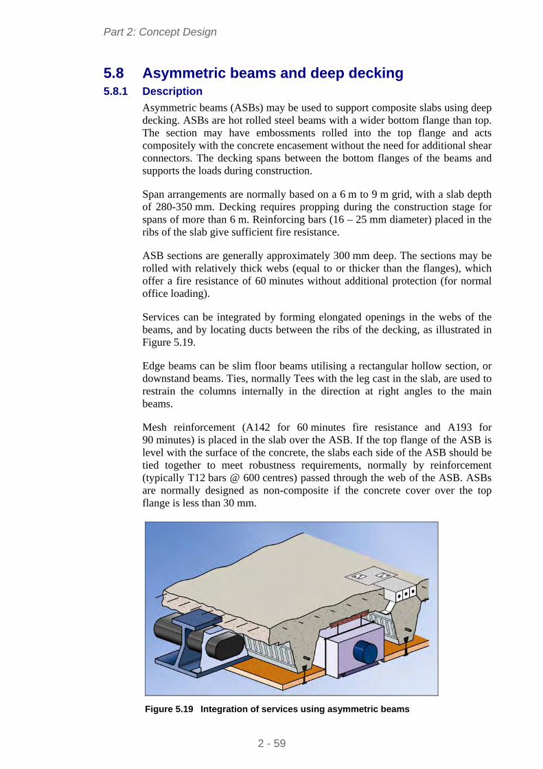
Part 2: Concept Design
5.8 Asymmetric beams and deep decking 5.8.1 Description
Asymmetric beams (ASBs) may be used to support composite slabs using deep decking. ASBs are hot rolled steel beams with a wider bottom flange than top. The section may have embossments rolled into the top flange and acts compositely with the concrete encasement without the need for additional shear connectors. The decking spans between the bottom flanges of the beams and supports the loads during construction.
Span arrangements are normally based on a 6 m to 9 m grid, with a slab depth of 280-350 mm. Decking requires propping during the construction stage for spans of more than 6 m. Reinforcing bars (16 – 25 mm diameter) placed in the ribs of the slab give sufficient fire resistance.
ASB sections are generally approximately 300 mm deep. The sections may be rolled with relatively thick webs (equal to or thicker than the flanges), which offer a fire resistance of 60 minutes without additional protection (for normal office loading).
Services can be integrated by forming elongated openings in the webs of the beams, and by locating ducts between the ribs of the decking, as illustrated in Figure 5.19.
Edge beams can be slim floor beams utilising a rectangular hollow section, or downstand beams. Ties, normally Tees with the leg cast in the slab, are used to restrain the columns internally in the direction at right angles to the main beams.
Mesh reinforcement (A142 for 60 minutes fire resistance and A193 for 90 minutes) is placed in the slab over the ASB. If the top flange of the ASB is level with the surface of the concrete, the slabs each side of the ASB should be tied together to meet robustness requirements, normally by reinforcement (typically T12 bars @ 600 centres) passed through the web of the ASB. ASBs are normally designed as non-composite if the concrete cover over the top flange is less than 30 mm.
Figure 5.19 Integration of services using asymmetric beams
2 - 59
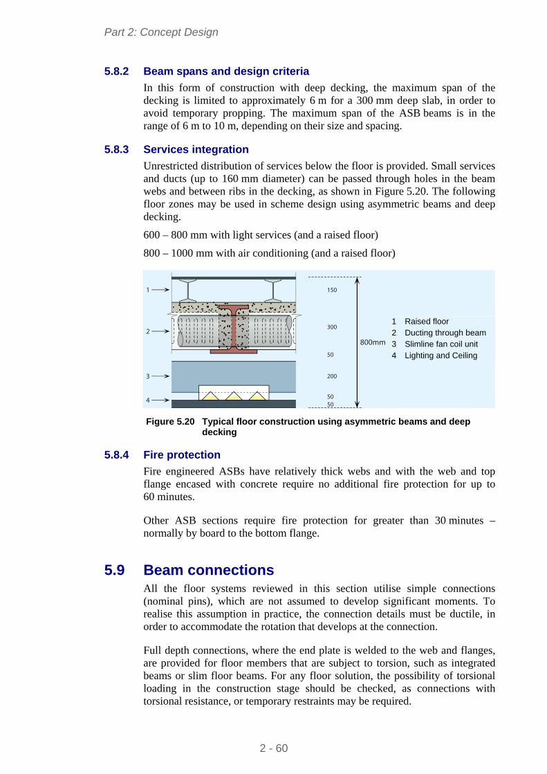
Part 2: Concept Design
5.8.2 Beam spans and design criteria
In this form of construction with deep decking, the maximum span of the decking is limited to approximately 6 m for a 300 mm deep slab, in order to avoid temporary propping. The maximum span of the ASB beams is in the range of 6 m to 10 m, depending on their size and spacing.
5.8.3 Services integration
Unrestricted distribution of services below the floor is provided. Small services and ducts (up to 160 mm diameter) can be passed through holes in the beam webs and between ribs in the decking, as shown in Figure 5.20. The following floor zones may be used in scheme design using asymmetric beams and deep decking.
600 – 800 mm with light services (and a raised floor)
800 – 1000 mm with air conditioning (and a raised floor)
150
300
50
800mm
200
5050
1
2
3
4
1 Raised floor 2 Ducting through beam 3 Slimline fan coil unit 4 Lighting and Ceiling
Figure 5.20 Typical floor construction using asymmetric beams and deep
decking
5.8.4 Fire protection
Fire engineered ASBs have relatively thick webs and with the web and top flange encased with concrete require no additional fire protection for up to 60 minutes.
Other ASB sections require fire protection for greater than 30 minutes – normally by board to the bottom flange.
5.9 Beam connections All the floor systems reviewed in this section utilise simple connections (nominal pins), which are not assumed to develop significant moments. To realise this assumption in practice, the connection details must be ductile, in order to accommodate the rotation that develops at the connection.
Full depth connections, where the end plate is welded to the web and flanges, are provided for floor members that are subject to torsion, such as integrated beams or slim floor beams. For any floor solution, the possibility of torsional loading in the construction stage should be checked, as connections with torsional resistance, or temporary restraints may be required.
2 - 60
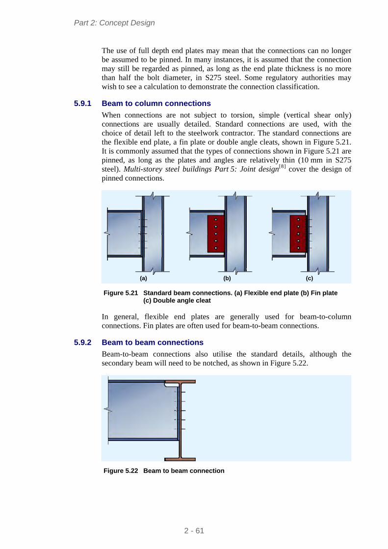
Part 2: Concept Design
The use of full depth end plates may mean that the connections can no longer be assumed to be pinned. In many instances, it is assumed that the connection may still be regarded as pinned, as long as the end plate thickness is no more than half the bolt diameter, in S275 steel. Some regulatory authorities may wish to see a calculation to demonstrate the connection classification.
5.9.1 Beam to column connections
When connections are not subject to torsion, simple (vertical shear only) connections are usually detailed. Standard connections are used, with the choice of detail left to the steelwork contractor. The standard connections are the flexible end plate, a fin plate or double angle cleats, shown in Figure 5.21. It is commonly assumed that the types of connections shown in Figure 5.21 are pinned, as long as the plates and angles are relatively thin (10 mm in S275 steel). Multi-storey steel buildings Part 5: Joint design[8] cover the design of pinned connections.
(a) (b) (c) Figure 5.21 Standard beam connections. (a) Flexible end plate (b) Fin plate
(c) Double angle cleat
In general, flexible end plates are generally used for beam-to-column connections. Fin plates are often used for beam-to-beam connections.
5.9.2 Beam to beam connections
Beam-to-beam connections also utilise the standard details, although the secondary beam will need to be notched, as shown in Figure 5.22.
Figure 5.22 Beam to beam connection
2 - 61
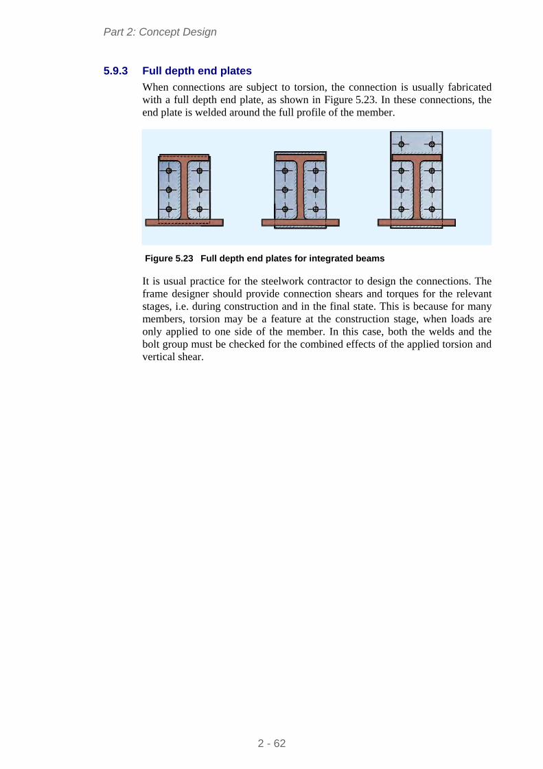
Part 2: Concept Design
5.9.3 Full depth end plates
When connections are subject to torsion, the connection is usually fabricated with a full depth end plate, as shown in Figure 5.23. In these connections, the end plate is welded around the full profile of the member.
Figure 5.23 Full depth end plates for integrated beams
It is usual practice for the steelwork contractor to design the connections. The frame designer should provide connection shears and torques for the relevant stages, i.e. during construction and in the final state. This is because for many members, torsion may be a feature at the construction stage, when loads are only applied to one side of the member. In this case, both the welds and the bolt group must be checked for the combined effects of the applied torsion and vertical shear.
2 - 62
Part 2: Concept Design
6 OTHER DESIGN ISSUES
The following design issues will affect the overall building concept, including the structural design aspects.
6.1 Accidental Actions EN 1990 requires that structures be designed for accidental design situations. The situations that need to be considered are set out in EN 1991-1-7, and these relate to both identified accidental actions and unidentified accidental actions. The strategy to be adopted in either case depends on three “consequence classes” that are set out in EN 1990; for buildings, one of those classes has been subdivided and the categories of building in each class are set out in EN 1991-1-7, Table A.1.
For identified accidental actions, design strategies include protecting the structure against the action but more generally, and for unidentified actions, the structure should be designed to have an appropriate level of “robustness”, defined as:
“The ability of a structure to withstand events like fire, explosions, impact or the consequences of human error, without being damaged to an extent disproportionate to the original cause.”
For unidentified actions, the strategy for achieving robustness is set out in EN 1991-1-7 § 3.3, which says that:
“… the potential failure of the structure arising from an unspecified cause shall be mitigated … by adopting one or more of the following approaches:
a) designing key elements on which the stability of the structure depends, to sustain the effects of a model of accidental action Ad;
b) designing the structure so that in the event of a localised failure (e.g. failure of a single member) the stability of the whole structure or of a significant part of it would not be endangered;
c) applying prescriptive design/detailing rules that provide acceptable robustness for the structure (e.g. three dimensional tying for additional integrity, or a minimum level of ductility of structural members subject to impact).”
6.1.1 Consequence classes
EN 1990 defines three consequences classes:
CC1 Low consequences of failure
CC2 Medium consequences of failure
CC3 High consequences of failure
2 - 63
Part 2: Concept Design
Class CC2 is subdivided by EN 1991-1-7 into CC2a (Lower risk group) and CC2b (Upper risk group). Medium rise buildings mostly fall with group CC2b. Examples of categories given by Table A.1 of EN 1991-1-7 include the following:
Table 6.1 Examples of building categorisation (taken from Table A.1 of EN 1991-1-7)
Consequence Class
Example of categorization of building type and occupancy
2B Upper Risk Group
Hotels, flats, apartments and other residential buildings greater than 4 storeys but not exceeding 15 storeys. Educational buildings greater than single storey but not exceeding 15 storeys. Retailing premises greater than 3 storeys but not exceeding 15 storeys. Offices greater than 4 storeys but not exceeding 15 storeys. All buildings to which the public are admitted and which contain floor areas exceeding 2000 m2 but not exceeding 5000 m2 at each storey.
The recommended strategy for Consequence Class 2b involves either the design for localised failure (see Section 6.1.2) or the design of columns as key elements (see Section 6.1.6).
6.1.2 Design for the consequences of localised failure in multi-storey buildings
In multi-storey buildings, the requirement for robustness generally leads to a design strategy where the columns are tied into the rest of the structure. This should mean that any one length of column cannot easily be removed. However, should a length be removed by an accidental action, the floor systems should be able to develop catenary action, to limit the extent of the failure.
It should be noted that the requirements are not intended to ensure that the structure is still serviceable following some extreme event, but that damage is limited, and that progressive collapse is prevented.
6.1.3 Horizontal tying
EN 1991-1-7, A.5 provides guidance on the horizontal tying of framed structures. It gives expressions for the design tensile resistance required for internal and perimeter ties. The calculated tying force is generally equal to the vertical shear.
Tying forces do not necessarily need to be carried by the steelwork frame. A composite concrete floor, for example, can be used to tie columns together, but must be designed to perform this function. Additional reinforcement may be required, and the columns (particularly edge columns) may need careful detailing to ensure the tying force is transferred between column and slab.
If the tying forces are to be carried by the structural steelwork alone, it should be noted that the check for tying resistance is entirely separate to that for resistance to vertical forces. The shear force and tying forces are never applied
2 - 64
Part 2: Concept Design
at the same time. Furthermore, the usual requirement that members and connections remain serviceable under design loading is ignored when calculating resistance to tying, as ‘substantial permanent deformation of members and their connections is acceptable’. Guidance on the design of connections to resist tying forces is given in Multi-storey steel buildings. Part 5: Joint design[8].
6.1.4 Tying of precast concrete floor units
EN 1991-1-7, §A.5.1 (2) requires that when concrete or other heavy floor units are used (as floors), they should be tied in the direction of their span. The intention is to prevent floor units or floor slabs simply falling through the steel frame, if the steelwork is moved or removed due to some major trauma. Slabs must be tied to each other over supports, and tied to edge beams. Tying forces may be determined from §9.10.2 of BS EN 1992-1-1.
6.1.5 Vertical tying
EN 1991-1-7, A.6 provides guidance on the vertical tying of framed structures. The clause recommends that column splices should be capable of carrying an axial tension equal to the largest design vertical permanent and variable load reaction applied to the column from any one storey. In practice, this is not an onerous obligation, and most splices designed for adequate stiffness and robustness during erection are likely to be sufficient to carry the axial tying force. Guidance on the design of splices to resist tying forces is given in other publications in this series Multi-storey steel buildings. Part 5: Joint design [8].
6.1.6 Key elements
EN 1991-1-7, A.8 provides guidance on the design of “Key elements”. It recommends that a key element should be capable of sustaining an accidental design action of Ad applied in horizontal and vertical directions (in one direction at a time) to the member and any attached components. The recommended value of Ad for building structures is 34 kN/m2. Any other structural component that provides “lateral restraint vital to the stability” of a key element should also be designed as a key element.
6.1.7 Risk assessment
Buildings which fall into consequence class 3 have to be assessed using risk assessment techniques. Annex B of EN 1991-1-7 provides information on risk assessment and B.9 provides guidance specific to buildings.
6.2 Floor dynamics Floor response is assessed first by calculating the fundamental frequency of the floor, and checking this against a limit. Limits are given in National regulations or technical guidance, and may vary between countries. Generally, if the fundamental frequency of the floor structure is greater than 4 Hz, the floor is usually considered to be satisfactory. The natural frequency of the floor is then at least twice the natural frequency due to rapid walking. Whilst this is generally acceptable for busy workplaces, it is not appropriate for quieter areas of buildings where vibrations are more perceptible.
2 - 65
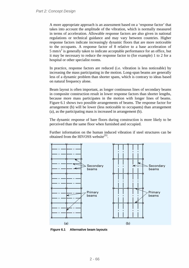
Part 2: Concept Design
A more appropriate approach is an assessment based on a ‘response factor’ that takes into account the amplitude of the vibration, which is normally measured in terms of acceleration. Allowable response factors are also given in national regulations or technical guidance and may vary between countries. Higher response factors indicate increasingly dynamic floors that are more noticeable to the occupants. A response factor of 8 relative to a base acceleration of 5 mm/s2 is generally taken to indicate acceptable performance for an office, but it may be necessary to reduce the response factor to (for example) 1 to 2 for a hospital or other specialist rooms.
In practice, response factors are reduced (i.e. vibration is less noticeable) by increasing the mass participating in the motion. Long-span beams are generally less of a dynamic problem than shorter spans, which is contrary to ideas based on natural frequency alone.
Beam layout is often important, as longer continuous lines of secondary beams in composite construction result in lower response factors than shorter lengths, because more mass participates in the motion with longer lines of beams. Figure 6.1 shows two possible arrangements of beams. The response factor for arrangement (b) will be lower (less noticeable to occupants) than arrangement (a), as the participating mass is increased in arrangement (b).
The dynamic response of bare floors during construction is more likely to be perceived than the same floor when furnished and occupied.
Further information on the human induced vibration if steel structures can be obtained from the HIVOSS website[9].
Primary beams
Secondarybeams
Secondarybeams
Primary beams
(a) (b) Figure 6.1 Alternative beam layouts
2 - 66
Part 2: Concept Design
6.3 Corrosion protection The corrosion of steel is an electrochemical process that requires the simultaneous presence of water and oxygen. In the absence of either, corrosion does not occur. Hence, for unprotected steel in dry environments (e.g. internal steelwork), corrosion will be minimal. The principal factors that determine the rate of corrosion of steel in air are the proportion of total time during which the surface is wet, due to rainfall, condensation etc, and the type and amount of atmospheric pollution (e.g. sulphates, chlorides, etc.).
External steelwork will need corrosion protection. The local environment is important, and can be broadly classified according to EN ISO 12944-2, which describes categories from C1 (heated interiors) through to C5 (aggressive marine or industrial environment). Many corrosion protection systems are available, including metallic coatings (such as galvanising) and paint systems, and should be chosen based on the environment classification.
Occasionally, local regulations demand that even interior steelwork or encased members must have corrosion protection, but in general, hidden steelwork inside dry, heated buildings requires no protection at all.
6.4 Temperature effects In theory, steel frames expand and contract with changes in temperature. Often, the temperature change of the steelwork itself is much lower than any change in the external temperature, because it is protected.
It is recommended that expansion joints are avoided if possible, since these are expensive and can be difficult to detail correctly to maintain a weather-tight external envelope. In preference to providing expansion joints, the frame may be analysed including the design effects of a temperature change. The temperature actions may be determined from EN 1991-1-5, and combinations of actions verified in accordance with EN 1990. In most cases, the members will be found to be adequate.
Common practice for multi-storey buildings in Northern Europe, in the absence of calculations, is that expansion joints do not need to be provided unless the length of the building exceeds 100 m for simple (braced) frames, and 50m in continuous construction. In warmer climates, common practice is to limit the length to around 80 m. These recommendations apply to the steel frame – expansion joints should be provided in stiff external cladding such as brickwork. When expansion joints in multi-storey buildings are provided, they are commonly arranged to coincide with significant changes of shape on plan, or at significant changes in floor level, or to separate parts of the structure on different foundations.
6.5 Fire safety Building designers should consider the implications of fire resistance when choosing the structural configuration and should address issues such as:
Means of escape.
2 - 67
Part 2: Concept Design
Size of compartment
Access and facilities for the Fire Service
Limiting the spread of fire
Smoke control and evacuation
Adoption of sprinklers.
Generally, the above issues are addressed by the scheme architect.
In addition to the above, structural performance in the event of a fire must meet prescribed standards, expressed as a period of fire resistance of the structural components. As an alternative, a ‘fire engineering’ approach may be followed which accounts for the fire safety of the whole building, considering the structure use, the hazards, the risks and how these are addressed.
In general, the structural engineer and architect should consider:
Schemes which have fewer beams to fire protect
The opportunity to use unprotected steelwork
The influence of service integration on the fire protection system, and appropriate solutions such as intumescent coatings on cellular beams
The influence that site applied protection may have on the construction programme, particularly if the protection is a spray
Requirements for the final appearance of exposed steelwork when choosing a fire protection system.
Guidance on the fire engineering of multi-storey steel structures is given in Multi-storey steel buildings. Part 6: Fire engineering[10].
6.6 Acoustic performance Limits on residual noise, after accounting for attenuation by the building façade, are usually specified in National regulations for open plan offices and conference rooms. Criteria are also usually given for the acceptable noise from building services in the same categories.
Maximum and minimum ambient noise level targets are generally defined for spaces within buildings. These are appropriate for comfort in both commercial premises and residential accommodation.
To meet acoustic performance standards, the construction details may require special attention. In Figure 6.2 precast concrete units have an isolated screed (a screed separated from the precast unit by a proprietary resilient layer, or by a waterproof membrane and dense mineral wool). In addition, the ceiling is not in direct contact with the steel beam, and is at least 8 kg/m2. Particular attention must also be paid to the junction where walls meet floors and ceilings (known as “flanking” details). An example of a typical flanking detail is shown in Figure 6.3, where there is dense mineral wool around the steel beam, sealant
2 - 68
Part 2: Concept Design
where the wall finish meets the ceiling, and sealant where the floor treatment meets the wall finish.
Figure 6.2 Typical floor treatment to provide improved acoustic performance
1
2
5
3
4
6
1 Dense mineral wool 2 Acoustic sealant 3 Mineral wool packing 4 Precast concrete unit 5 Floor treatment 6 Sealant Figure 6.3 Typical flanking detail for an internal separating wall
Separating walls between occupancies are likely to be of double skin construction to reduce noise transmission, facilitating the use of bracing within the wall construction.
2 - 69
Part 2: Concept Design
6.7 Energy efficiency Thermal insulation provided in the building envelope is traditionally the architect’s responsibility. However, the structural engineer must be involved in the development of appropriate details and layout. Supporting systems for cladding may be more complicated in order to meet thermal performance requirements, involving eccentric connection to the supporting steelwork. Steel members that penetrate the insulation, such as balcony supports, need special consideration and detailing to avoid ‘thermal bridging’. Thermal bridges not only lead to heat loss, but may also lead to condensation on the inside of the building.
6.8 Cladding Cladding systems that may be used in multi-storey building depend on the building height and the degree of fenestration. Fully glazed facades are widely used, although provision for solar shading generally has to be made. An example of a fully glazed cladding is shown in Figure 6.4. The following cladding systems are generally:
Brickwork Ground supported up to 3 storeys. Supported by stainless steel angles attached to edge beams for taller buildings
Glazing systems Generally triple glazing or double layer facades supported on aluminium posts or glass fins
Curtain walling Aluminium or other lightweight façade that is attached to the perimeter steelwork
Insulated render or tiles Cladding system supported on light steel infill walls, mainly used in public sector buildings and residential buildings.
2 - 70
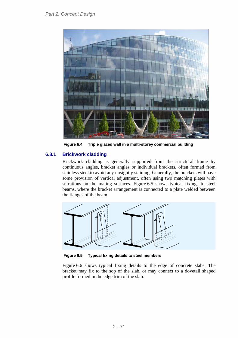
Part 2: Concept Design
Figure 6.4 Triple glazed wall in a multi-storey commercial building
6.8.1 Brickwork cladding
Brickwork cladding is generally supported from the structural frame by continuous angles, bracket angles or individual brackets, often formed from stainless steel to avoid any unsightly staining. Generally, the brackets will have some provision of vertical adjustment, often using two matching plates with serrations on the mating surfaces. Figure 6.5 shows typical fixings to steel beams, where the bracket arrangement is connected to a plate welded between the flanges of the beam.
Figure 6.5 Typical fixing details to steel members
Figure 6.6 shows typical fixing details to the edge of concrete slabs. The bracket may fix to the sop of the slab, or may connect to a dovetail shaped profile formed in the edge trim of the slab.
2 - 71
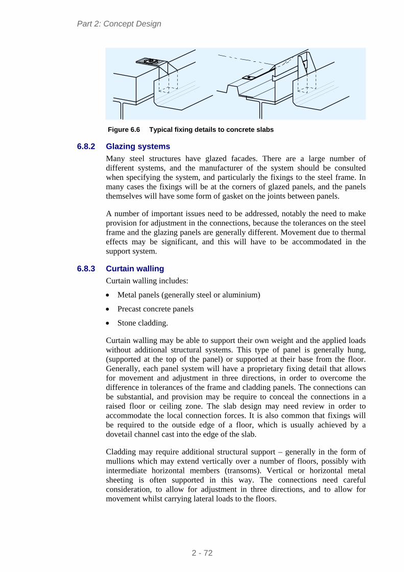
Part 2: Concept Design
Figure 6.6 Typical fixing details to concrete slabs
6.8.2 Glazing systems
Many steel structures have glazed facades. There are a large number of different systems, and the manufacturer of the system should be consulted when specifying the system, and particularly the fixings to the steel frame. In many cases the fixings will be at the corners of glazed panels, and the panels themselves will have some form of gasket on the joints between panels.
A number of important issues need to be addressed, notably the need to make provision for adjustment in the connections, because the tolerances on the steel frame and the glazing panels are generally different. Movement due to thermal effects may be significant, and this will have to be accommodated in the support system.
6.8.3 Curtain walling
Curtain walling includes:
Metal panels (generally steel or aluminium)
Precast concrete panels
Stone cladding.
Curtain walling may be able to support their own weight and the applied loads without additional structural systems. This type of panel is generally hung, (supported at the top of the panel) or supported at their base from the floor. Generally, each panel system will have a proprietary fixing detail that allows for movement and adjustment in three directions, in order to overcome the difference in tolerances of the frame and cladding panels. The connections can be substantial, and provision may be require to conceal the connections in a raised floor or ceiling zone. The slab design may need review in order to accommodate the local connection forces. It is also common that fixings will be required to the outside edge of a floor, which is usually achieved by a dovetail channel cast into the edge of the slab.
Cladding may require additional structural support – generally in the form of mullions which may extend vertically over a number of floors, possibly with intermediate horizontal members (transoms). Vertical or horizontal metal sheeting is often supported in this way. The connections need careful consideration, to allow for adjustment in three directions, and to allow for movement whilst carrying lateral loads to the floors.
2 - 72
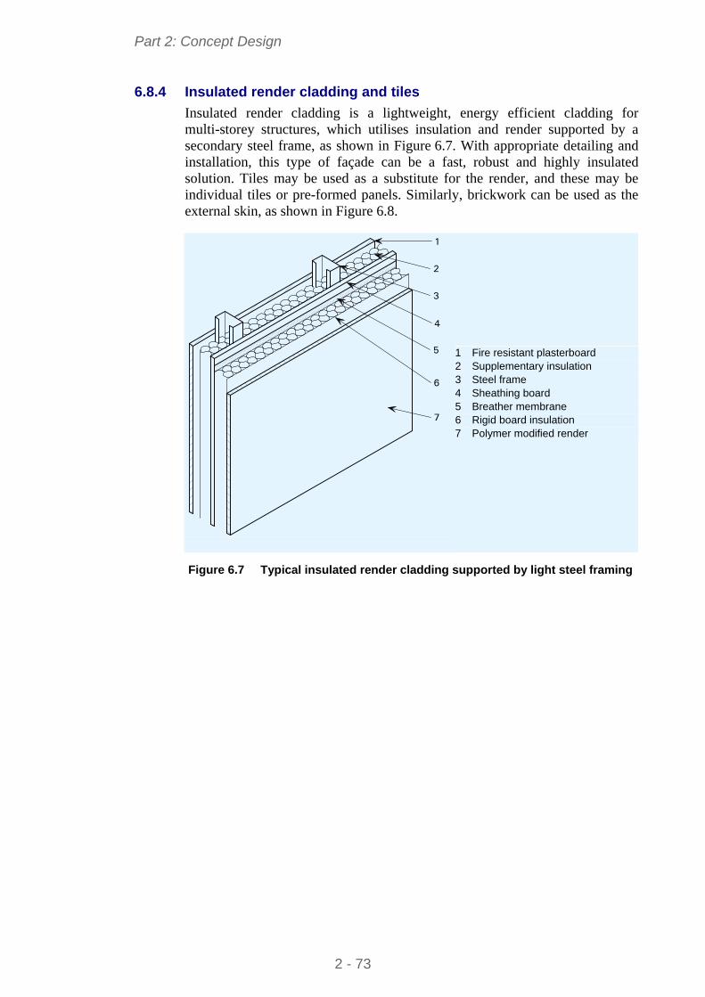
Part 2: Concept Design
6.8.4 Insulated render cladding and tiles
Insulated render cladding is a lightweight, energy efficient cladding for multi-storey structures, which utilises insulation and render supported by a secondary steel frame, as shown in Figure 6.7. With appropriate detailing and installation, this type of façade can be a fast, robust and highly insulated solution. Tiles may be used as a substitute for the render, and these may be individual tiles or pre-formed panels. Similarly, brickwork can be used as the external skin, as shown in Figure 6.8.
7
6
5
2
3
1
4
1 Fire resistant plasterboard 2 Supplementary insulation 3 Steel frame 4 Sheathing board 5 Breather membrane 6 Rigid board insulation 7 Polymer modified render
Figure 6.7 Typical insulated render cladding supported by light steel framing
2 - 73
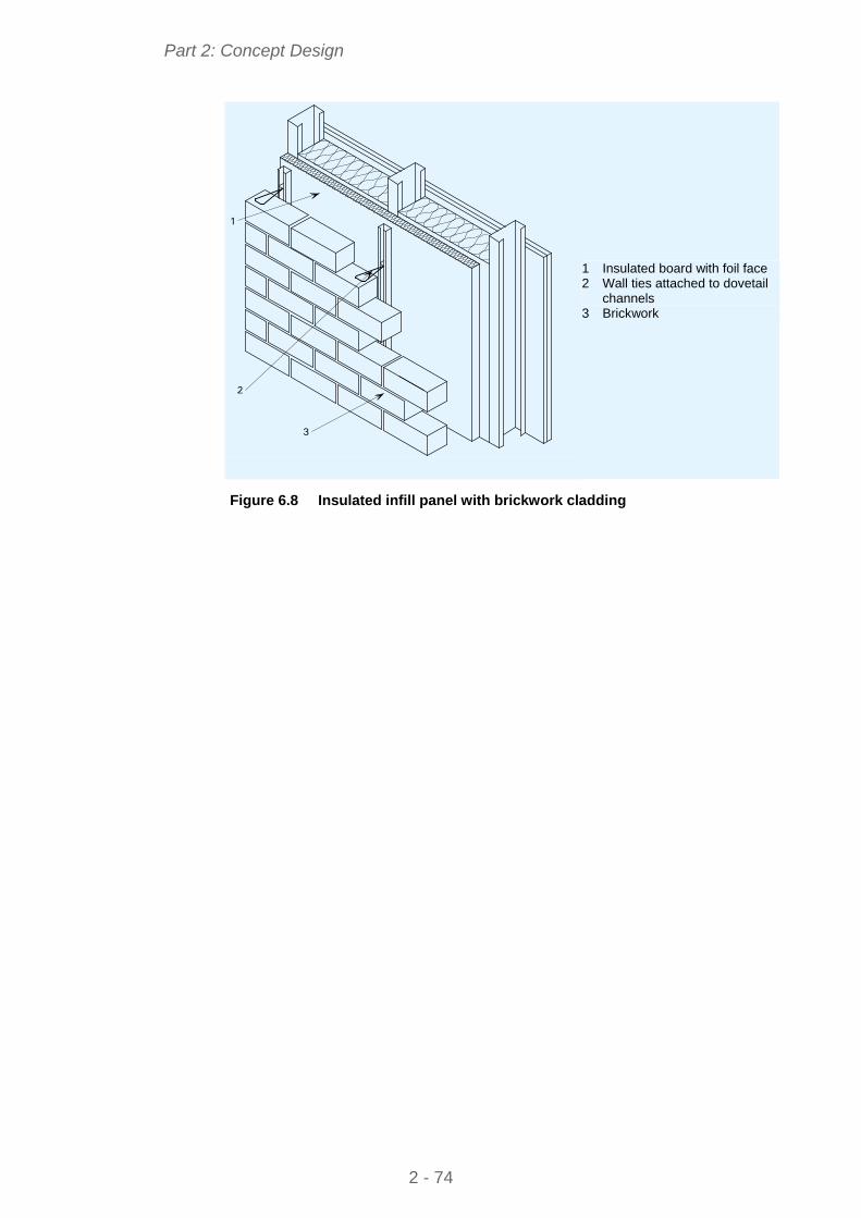
Part 2: Concept Design
3
1
2
1 Insulated board with foil face 2 Wall ties attached to dovetail
channels
3 Brickwork
Figure 6.8 Insulated infill panel with brickwork cladding
2 - 74
Part 2: Concept Design
2 - 75
REFERENCES
1 HICKS, S. J., LAWSON, R. M., RACKHAM, J. W. and FORDHAM, P. Comparative structure cost of modern commercial buildings (second edition) The Steel Construction Institute, 2004
2 Steel Buildings in Europe Multi-storey steel buildings. Part 3: Actions
3 SANSOM, M & MEIJER, J Life-cycle assessment (LCA) for steel construction European commission, 2002
4 Several assessment methods are used. For example:
BREEAM in the UK
HQE in France
DNGB in Germany
BREEAM-NL, Greencalc+ and BPR Gebouw in the Netherlands
Valideo in Belgium
Casa Clima in Trento Alto Adige, Italy (each region has its own approach)
LEED, used in various countries
5 GORGOLEWSKI, M. The role of steel in environmentally responsible buildings The Steel Construction Institute, 1999
6 Steel Buildings in Europe Multi-storey steel building. Part 4: Detailed design
7 SIMMS, W.I. RT 983: Interim guidance on the use of intumescent coatings for the fire protection of beams The Steel Construction Institute, 2004
8 Steel Buildings in Europe Multi-storey steel buildings. Part 5: Joint design
9 http://www.stb.rwth-aachen.de/projekte/2007/HIVOSS/download.php
10 Steel Buildings in Europe Multi-storey steel buildings. Part 6: Fire engineering
STEEL BUILDINGS IN EUROPE
Multi-Storey Steel Buildings
Part 3: Actions

Multi-Storey Steel Buildings
Part 3: Actions

3 - ii
Part 3: Actions
3 - iii
FOREWORD
This publication is part three of a design guide, Multi-Storey Steel Buildings.
The 10 parts in the Multi-Storey Steel Buildings guide are:
Part 1: Architect’s guide
Part 2: Concept design
Part 3: Actions
Part 4: Detailed design
Part 5: Joint design
Part 6: Fire Engineering
Part 7: Model construction specification
Part 8: Design software – section capacity
Part 9: Design software – simple connections
Part 10: Software specification for composite beams.
Multi-Storey Steel Buildings is one of two design guides. The second design guide is Single-Storey Steel Buildings.
The two design guides have been produced in the framework of the European project “Facilitating the market development for sections in industrial halls and low rise buildings (SECHALO) RFS2-CT-2008-0030”.
The design guides have been prepared under the direction of Arcelor Mittal, Peiner Träger and Corus. The technical content has been prepared by CTICM and SCI, collaborating as the Steel Alliance.

Part 3: Actions
3 - iv
Part 3: Actions
3 - v
Contents Page No
FOREWORD iii
SUMMARY vi
1 INTRODUCTION 1
2 SAFETY PHILOSOPHY ACCORDING TO EN 1990 2 2.1 General format of the verifications 2 2.2 Ultimate limit states and serviceability limit states 2 2.3 Characteristic values and design values of actions 3
3 COMBINATIONS OF ACTIONS 4 3.1 General 4 3.2 ULS combinations 4 3.3 SLS combinations 6
4 PERMANENT ACTIONS 8
5 CONSTRUCTION LOADS 9
6 IMPOSED LOADS 10 6.1 General 10 6.2 Reduction due to the loaded area 10 6.3 Reduction due to the number of storeys 11 6.4 Horizontal loads on parapets 11
7 SNOW LOADS 12
8 WIND ACTION 13 8.1 General 13 8.2 Structural factor cscd 13
9 EFFECT OF TEMPERATURE 18
REFERENCES 19
APPENDIX A Worked Example – Wind action on a multi-storey building 21
Part 3: Actions
3 - vi
SUMMARY
This document provides guidelines for the determination of the loads on a common multi-storey building, according to EN 1990 and EN 1991. After a short description of the general format for limit state design, this guide provides information on the determination of the permanent actions, the variable actions and the combinations of actions. This guide also includes a worked example on the wind action on a multi-storey building.
Part 3: Actions
3 - 1
1 INTRODUCTION
This guide provides essential information on the determination of the design actions on a multi-storey building. It describes the basis of design with reference to the limit state concept in conjunction with the partial factor method, according to the following parts of the Eurocodes:
EN 1990: Basis of structural design[1]
EN 1991: Actions on structures
- Part 1-1: General actions – Densities, self-weight, imposed loads for buildings[2]
- Part 1-3: General actions – Snow loads[3]
- Part 1-4: General actions – Wind actions[4]
- Part 1-5: General actions – Thermal actions[5]
- Part 1-6: General actions – Actions during execution.[6]
Part 3: Actions
3 - 2
2 SAFETY PHILOSOPHY ACCORDING TO EN 1990
2.1 General format of the verifications A distinction is made between ultimate limit states (ULS) and serviceability limit states (SLS).
The ultimate limit states are related to the following design situations:
Persistent design situations (conditions of normal use)
Transient design situations (temporary conditions applicable to the structure, e.g. during execution, repair, etc.)
Accidental design situations (exceptional conditions applicable to the structure)
Seismic design situations (conditions applicable to the structure when subjected to seismic events). These events are dealt with in EN 1998[7], and are outside the scope of this guide.
The serviceability limit states concern the functioning of the structure under normal use, the comfort of people and the appearance of the construction.
The verifications shall be carried out for all relevant design situations and load cases.
2.2 Ultimate limit states and serviceability limit states 2.2.1 Ultimate limit states (ULS)
The states classified as ultimate limit states are those that concern the safety of people and /or the safety of the structure. The structure shall be verified at ULS when there is:
Loss of equilibrium of the structure or any part of it (EQU)
Failure by excessive deformation, rupture, loss of stability of the structure or any part of it (STR)
Failure or excessive deformation of the ground (GEO)
Failure caused by fatigue or other time-dependent effects (FAT).
2.2.2 Serviceability limit states (SLS)
The structure shall be verified at SLS when there is:
Deformations that affect the appearance, the comfort of users or the functioning of the structure
Vibrations that cause discomfort to people or that limit the functional effectiveness of the structure
Damage that is likely to adversely affect the appearance, the durability or the functioning of the structure.
Part 3: Actions
3 - 3
2.3 Characteristic values and design values of actions
2.3.1 General
Actions shall be classified by their variation in time as follows:
Permanent actions (G), e.g. self-weight of structures, fixed equipment, etc.
Variable actions (Q), e.g. imposed loads, wind actions, snow loads, etc.
Accidental actions (A), e.g. explosions, impact from vehicles, etc.
Certain actions may be considered as either accidental and/or variable actions, e.g. seismic actions, snow loads, wind actions with some design situations.
2.3.2 Characteristic values of actions
The characteristic value (Fk) of an action is its principal representative value. As it can be defined on statistical bases, it is chosen so as to correspond to a prescribed probability of not exceeding on the unfavourable side, during a “reference period” taking into account the design working life of the structure.
These characteristic values are specified in the various Parts of EN 1991.
2.3.3 Design values of actions
The design value Fd of an action F can be expressed in general terms as:
Fd = f Fk
where:
Fk is the characteristic value of the action
f is a partial factor for the action
is either 1,00, 0, 1 or 2
2.3.4 Partial factors
Partial factors are used to verify the structures at ULS and SLS. They should be obtained from EN 1990 Annex A1, or from EN 1991 or from the relevant National Annex.
2.3.5 factors
In the combinations of actions, factors apply to variable actions in order to take into account the reduced probability of simultaneous occurrence of their characteristic values.
The recommended values for factors for buildings should be obtained from EN 1990 Annex A1 Table A1.1, or from EN 1991 or from the relevant National Annex.
Part 3: Actions
3 - 4
3 COMBINATIONS OF ACTIONS
3.1 General The individual actions should be combined so as not to exceed the limit state for the relevant design situations.
Actions that cannot occur simultaneously, e.g. due to physical reasons, should not be considered together in a same combination.
Depending on its uses and the form and the location of a building, the combinations of actions may be based on not more than two variable actions – See Note 1 in EN 1990 § A1.2.1(1). The National Annex may provide additional information.
3.2 ULS combinations 3.2.1 Static equilibrium
To verify a limit state of static equilibrium of the structure (EQU), it shall be ensured that:
Ed,dst ≤ Ed,stb
where:
Ed,dst is the design value of the effect of destabilising actions
Ed,stb is the design value of the effect of stabilising actions
3.2.2 Rupture or excessive deformation of an element
To verify a limit state of rupture or excessive deformation of a section, member or connection (STR and/or GEO), it shall be ensured that:
Ed ≤ Rd
where:
Ed is the design value of the effect of actions
Rd is the design value of the corresponding resistance
Each combination of actions should include a leading variable action or an accidental action.
3.2.3 Combinations of actions for persistent or transient design situations
According to EN 1990 § 6.4.3.2(3), the combinations of actions can be derived either from expression (6.10) or from expressions (6.10a and 6.10b – whichever is more onerous). The choice between these two sets of expressions may be imposed by the National Annex.
In general, expression (6.10) is conservative in comparison to the pair of expressions (6.10a and 6.10b), but it leads to a reduced number of combinations to consider.
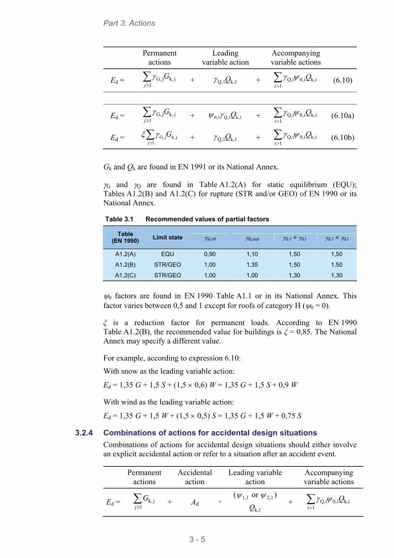
Part 3: Actions
3 - 5
Permanent
actions
Leading variable action
Accompanying variable actions
Ed = 1
jk,jG,j
G + k,1Q,1Q + 1
ik,i0,iQ,i
Q (6.10)
Ed = 1
jk,jG,j
G + k,1Q,10,1 Q + 1
ik,i0,iQ,i
Q (6.10a)
Ed = 1
jk,jG,j
G + k,1Q,1Q + 1
ik,i0,iQ,i
Q (6.10b)
Gk and Qk are found in EN 1991 or its National Annex.
G and Q are found in Table A1.2(A) for static equilibrium (EQU); Tables A1.2(B) and A1.2(C) for rupture (STR and/or GEO) of EN 1990 or its National Annex.
Table 3.1 Recommended values of partial factors
Table (EN 1990)
Limit state Gj,inf Gj,sup Q,1 = Q,I Q,1 = Q,I
A1.2(A) EQU 0,90 1,10 1,50 1,50
A1.2(B) STR/GEO 1,00 1,35 1,50 1,50
A1.2(C) STR/GEO 1,00 1,00 1,30 1,30
0 factors are found in EN 1990 Table A1.1 or in its National Annex. This factor varies between 0,5 and 1 except for roofs of category H (0 = 0).
ξ is a reduction factor for permanent loads. According to EN 1990 Table A1.2(B), the recommended value for buildings is ξ = 0,85. The National Annex may specify a different value.
For example, according to expression 6.10:
With snow as the leading variable action:
Ed = 1,35 G + 1,5 S + (1,5 0,6) W = 1,35 G + 1,5 S + 0,9 W
With wind as the leading variable action:
Ed = 1,35 G + 1,5 W + (1,5 0,5) S = 1,35 G + 1,5 W + 0,75 S
3.2.4 Combinations of actions for accidental design situations
Combinations of actions for accidental design situations should either involve an explicit accidental action or refer to a situation after an accident event.
Permanent
actions
Accidental action
Leading variable
action
Accompanying variable actions
Ed = 1
jk,j
G + Ad +( 1,1 or 2,1 )
k,1Q +
1ik,i0,iQ,
i
Q
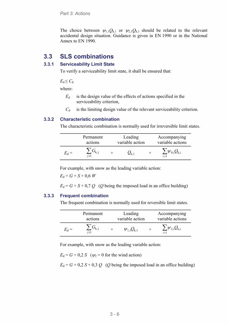
Part 3: Actions
3 - 6
The choice between 1,1Qk,1 or 2,1Qk,1 should be related to the relevant accidental design situation. Guidance is given in EN 1990 or in the National Annex to EN 1990.
3.3 SLS combinations 3.3.1 Serviceability Limit State
To verify a serviceability limit state, it shall be ensured that:
Ed ≤ Cd
where:
Ed is the design value of the effects of actions specified in the serviceability criterion,
Cd is the limiting design value of the relevant serviceability criterion.
3.3.2 Characteristic combination
The characteristic combination is normally used for irreversible limit states.
Permanent
actions
Leading variable action
Accompanying variable actions
Ed = 1
jk,j
G + k,1Q + 1
ik,i0,i
Q
For example, with snow as the leading variable action:
Ed = G + S + 0,6 W
Ed = G + S + 0,7 Q (Q being the imposed load in an office building)
3.3.3 Frequent combination
The frequent combination is normally used for reversible limit states.
Permanent
actions
Leading variable action
Accompanying variable actions
Ed = 1
jk,j
G + k,11,1Q + 1
ik,i2,i
Q
For example, with snow as the leading variable action:
Ed = G + 0,2 S (2 = 0 for the wind action)
Ed = G + 0,2 S + 0,3 Q (Q being the imposed load in an office building)
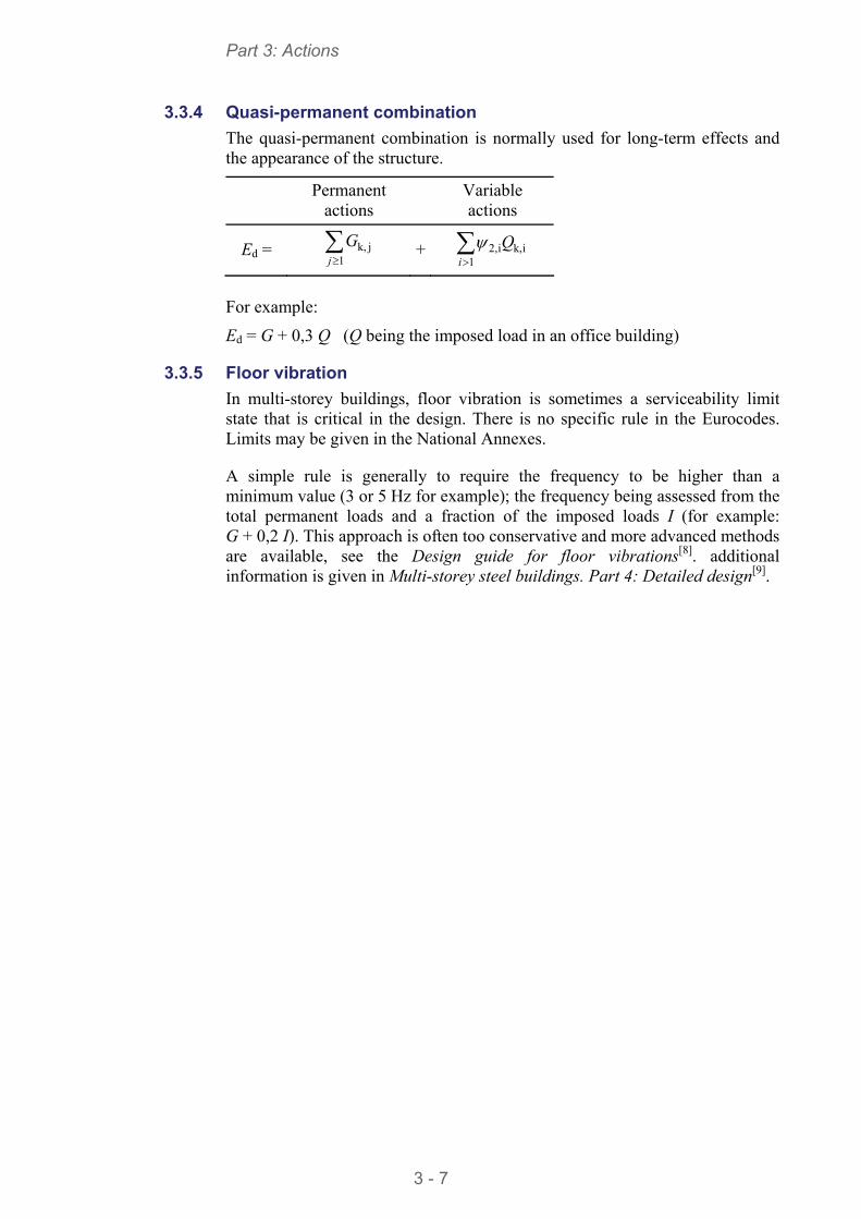
Part 3: Actions
3 - 7
3.3.4 Quasi-permanent combination
The quasi-permanent combination is normally used for long-term effects and the appearance of the structure.
Permanent
actions
Variable actions
Ed = 1
jk,j
G + 1
ik,i2,i
Q
For example:
Ed = G + 0,3 Q (Q being the imposed load in an office building)
3.3.5 Floor vibration
In multi-storey buildings, floor vibration is sometimes a serviceability limit state that is critical in the design. There is no specific rule in the Eurocodes. Limits may be given in the National Annexes.
A simple rule is generally to require the frequency to be higher than a minimum value (3 or 5 Hz for example); the frequency being assessed from the total permanent loads and a fraction of the imposed loads I (for example: G + 0,2 I). This approach is often too conservative and more advanced methods are available, see the Design guide for floor vibrations[8]. additional information is given in Multi-storey steel buildings. Part 4: Detailed design[9].
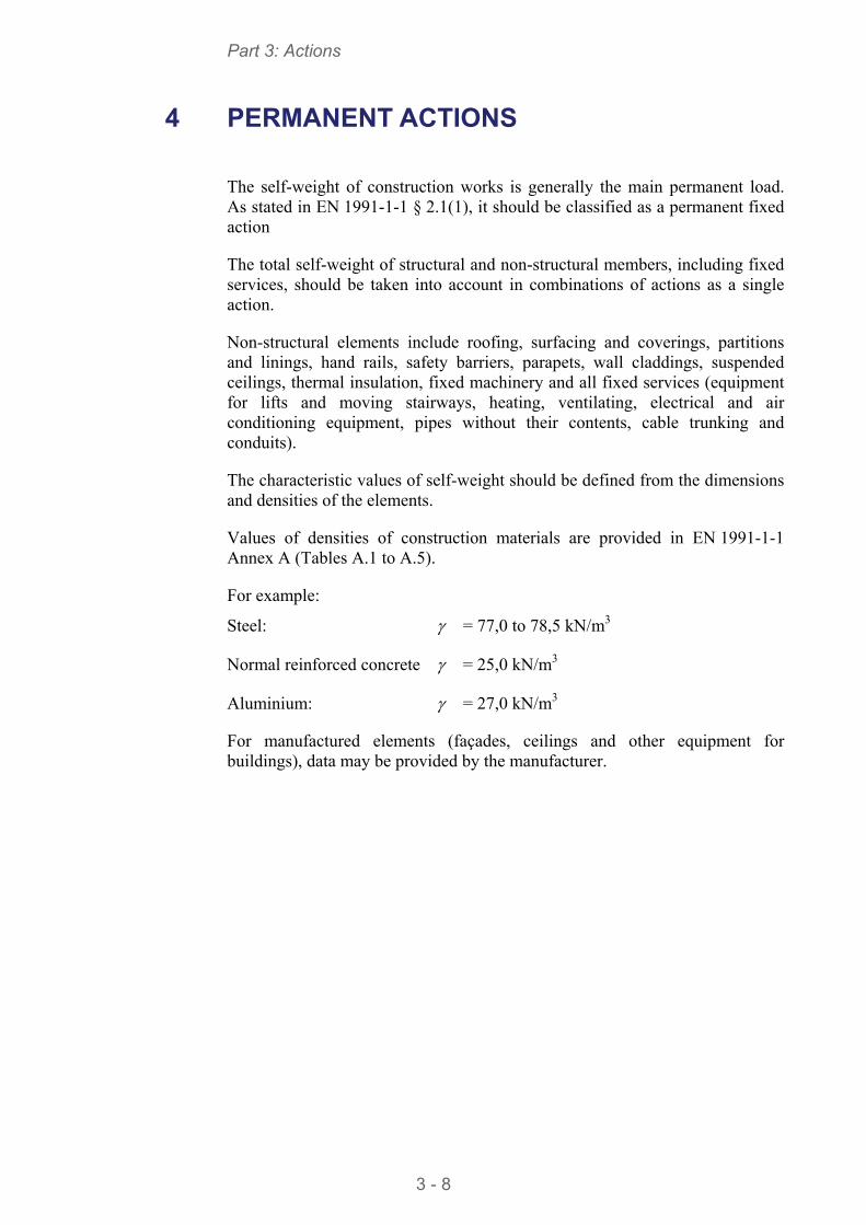
Part 3: Actions
3 - 8
4 PERMANENT ACTIONS
The self-weight of construction works is generally the main permanent load. As stated in EN 1991-1-1 § 2.1(1), it should be classified as a permanent fixed action
The total self-weight of structural and non-structural members, including fixed services, should be taken into account in combinations of actions as a single action.
Non-structural elements include roofing, surfacing and coverings, partitions and linings, hand rails, safety barriers, parapets, wall claddings, suspended ceilings, thermal insulation, fixed machinery and all fixed services (equipment for lifts and moving stairways, heating, ventilating, electrical and air conditioning equipment, pipes without their contents, cable trunking and conduits).
The characteristic values of self-weight should be defined from the dimensions and densities of the elements.
Values of densities of construction materials are provided in EN 1991-1-1 Annex A (Tables A.1 to A.5).
For example:
Steel: = 77,0 to 78,5 kN/m3
Normal reinforced concrete = 25,0 kN/m3
Aluminium: = 27,0 kN/m3
For manufactured elements (façades, ceilings and other equipment for buildings), data may be provided by the manufacturer.
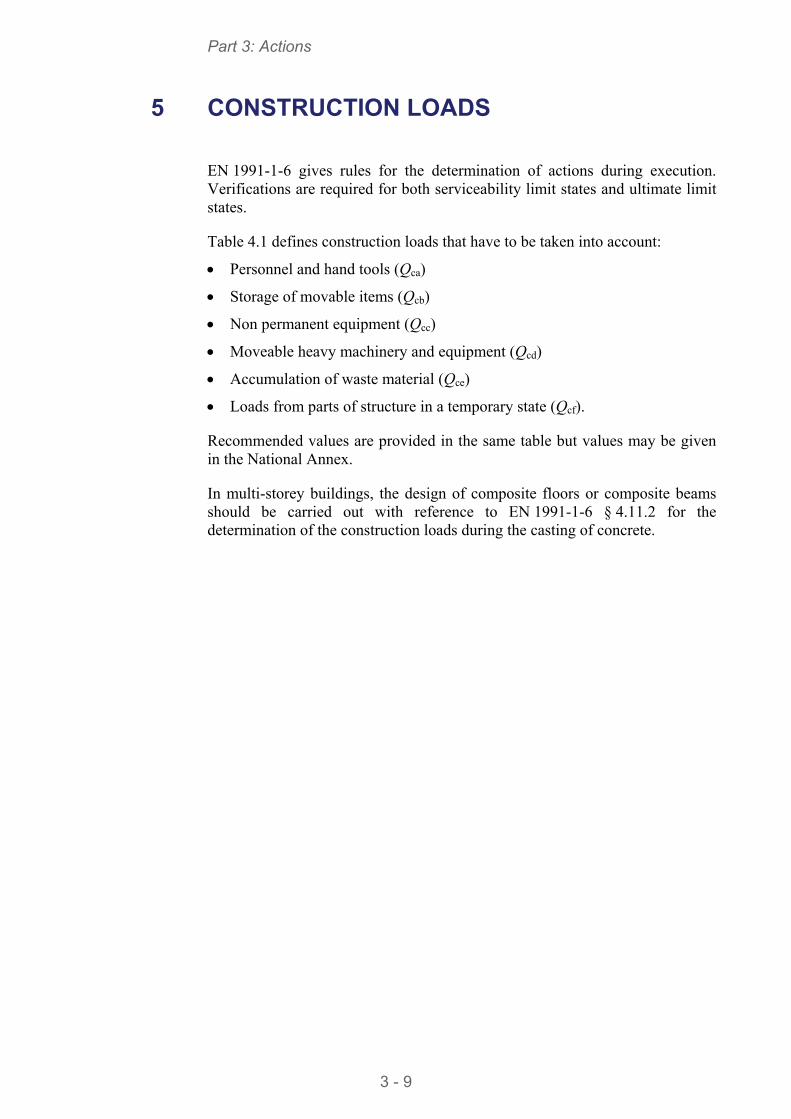
Part 3: Actions
3 - 9
5 CONSTRUCTION LOADS
EN 1991-1-6 gives rules for the determination of actions during execution. Verifications are required for both serviceability limit states and ultimate limit states.
Table 4.1 defines construction loads that have to be taken into account:
Personnel and hand tools (Qca)
Storage of movable items (Qcb)
Non permanent equipment (Qcc)
Moveable heavy machinery and equipment (Qcd)
Accumulation of waste material (Qce)
Loads from parts of structure in a temporary state (Qcf).
Recommended values are provided in the same table but values may be given in the National Annex.
In multi-storey buildings, the design of composite floors or composite beams should be carried out with reference to EN 1991-1-6 § 4.11.2 for the determination of the construction loads during the casting of concrete.
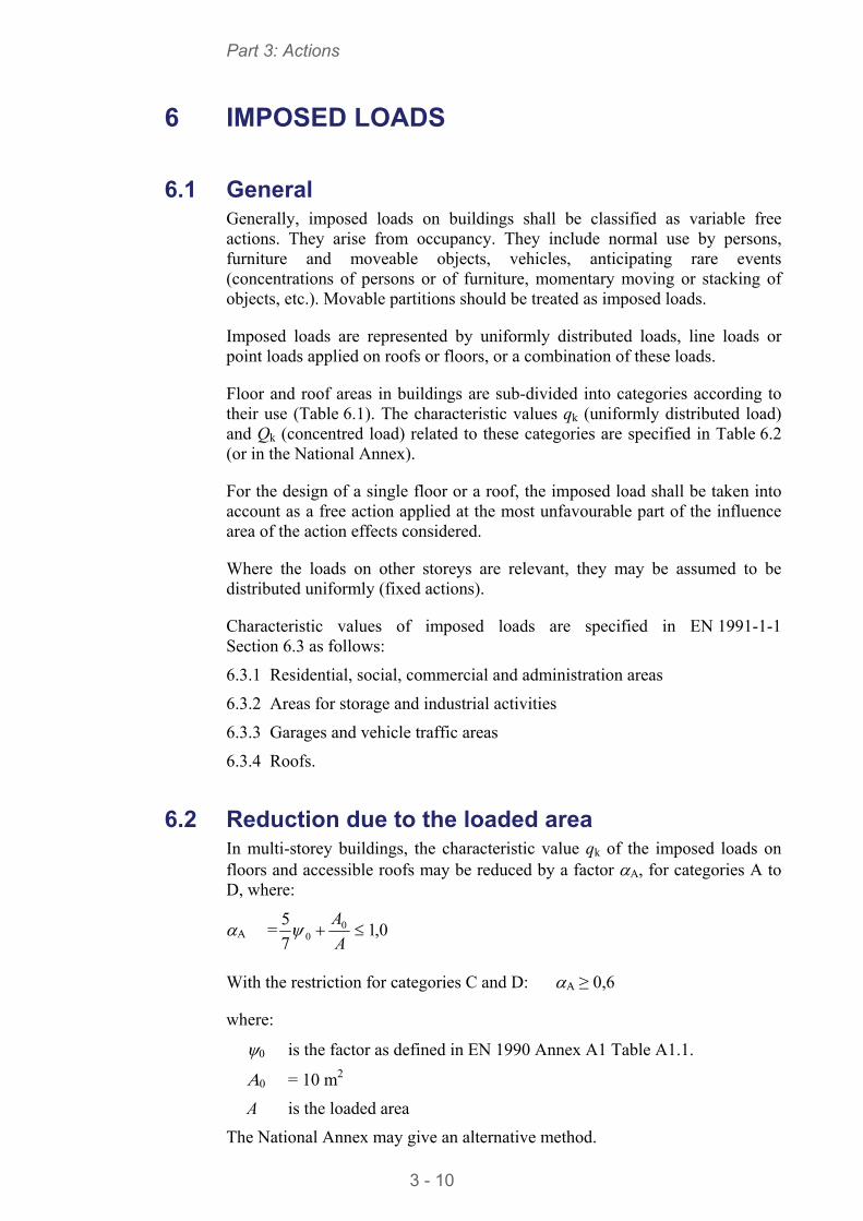
Part 3: Actions
3 - 10
6 IMPOSED LOADS
6.1 General Generally, imposed loads on buildings shall be classified as variable free actions. They arise from occupancy. They include normal use by persons, furniture and moveable objects, vehicles, anticipating rare events (concentrations of persons or of furniture, momentary moving or stacking of objects, etc.). Movable partitions should be treated as imposed loads.
Imposed loads are represented by uniformly distributed loads, line loads or point loads applied on roofs or floors, or a combination of these loads.
Floor and roof areas in buildings are sub-divided into categories according to their use (Table 6.1). The characteristic values qk (uniformly distributed load) and Qk (concentred load) related to these categories are specified in Table 6.2 (or in the National Annex).
For the design of a single floor or a roof, the imposed load shall be taken into account as a free action applied at the most unfavourable part of the influence area of the action effects considered.
Where the loads on other storeys are relevant, they may be assumed to be distributed uniformly (fixed actions).
Characteristic values of imposed loads are specified in EN 1991-1-1 Section 6.3 as follows:
6.3.1 Residential, social, commercial and administration areas
6.3.2 Areas for storage and industrial activities
6.3.3 Garages and vehicle traffic areas
6.3.4 Roofs.
6.2 Reduction due to the loaded area In multi-storey buildings, the characteristic value qk of the imposed loads on floors and accessible roofs may be reduced by a factor A, for categories A to D, where:
A = 0,17
5 00
A
A
With the restriction for categories C and D: A ≥ 0,6
where:
0 is the factor as defined in EN 1990 Annex A1 Table A1.1.
0 = 10 m2
A is the loaded area
The National Annex may give an alternative method.
Part 3: Actions
3 - 11
6.3 Reduction due to the number of storeys For the design of columns and walls, loaded from several storeys, the total imposed loads on the floor of each storey should be assumed to be distributed uniformly.
For columns and walls, the total imposed loads may be reduced by a factor n, for categories A to D, where:
n = 0
)2(2 n
n
where:
0 is is the factor as defined in EN 1990 Annex A1 Table A1.1.
n is the number of storeys (> 2) above the loaded structural elements in the same category.
The National Annex may give an alternative method.
6.4 Horizontal loads on parapets The characteristic values of the line loads qk acting at the height of the partition walls or parapets but not higher than 1,20 m should be taken from EN 1991-1-1 Table 6.12, which provides recommended values. Other values may be given in the National Annex.
For areas susceptible to significant overcrowding associated with public events (stages, assembly halls, conference rooms), the load should be taken according to category C5 from EN 1991-1-1 Table 6.1.
For office buildings (category B), the recommended value from EN 1991-1-1 Table 6.12 is:
qk = 0,2 to 1,0 kN/m
The National Annex may define other values.

Part 3: Actions
3 - 12
7 SNOW LOADS
There is no issue in the calculation of snow loads specifically related to multi-storey buildings. Full information including a worked example is provided in Single-storey steel buildings. Part 3: Actions[10].
Part 3: Actions
3 - 13
8 WIND ACTION
8.1 General The determination of the wind action according to EN 1991-1-4[4] is described in Single-storey steel buildings. Part 3:– Actions [10] for a single storey building. For a multi-storey building, the calculation is nearly the same, except for two aspects:
The calculation of the structural factor cscd
For slender buildings, the external pressure coefficients must be calculated for different strips along the height of the building.
According to EN 1991-1-4 § 6.2(1), the structural factor may be taken equal to 1 when the height of the building is lower than 15 m, which is commonly the case for single storey buildings. For multi-storey buildings, which are commonly higher than 15 m, the structural factor has to be determined. Section 8.2 provides the main steps of this calculation according to EN 1991-1-4 § 6.3.1(1).
A detailed example including the full calculation of the wind action on a multi-storey building is given in Appendix A.
8.2 Structural factor cscd The structural factor cscd should be calculated for the main wind directions, using the equation given EN 1991-1-4 § 6.3.1(1), provided that:
The building shape is a rectangular, parallel sided as stated in EN 1991-1-4 § 6.3.1(2) and Figure 6.1
The along-wind vibration in the fundamental mode is significant and the mode shape has a constant sign.
This calculation requires the determination of several intermediate parameters.
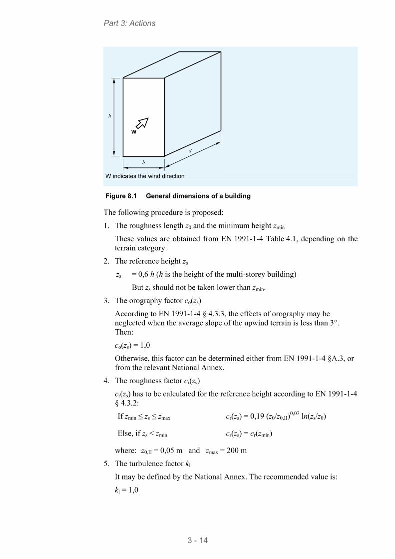
Part 3: Actions
3 - 14
b
d
h
W
W indicates the wind direction
Figure 8.1 General dimensions of a building
The following procedure is proposed:
1. The roughness length z0 and the minimum height zmin
These values are obtained from EN 1991-1-4 Table 4.1, depending on the terrain category.
2. The reference height zs
zs = 0,6 h (h is the height of the multi-storey building)
But zs should not be taken lower than zmin.
3. The orography factor co(zs)
According to EN 1991-1-4 § 4.3.3, the effects of orography may be neglected when the average slope of the upwind terrain is less than 3°. Then:
co(zs) = 1,0
Otherwise, this factor can be determined either from EN 1991-1-4 §A.3, or from the relevant National Annex.
4. The roughness factor cr(zs)
cr(zs) has to be calculated for the reference height according to EN 1991-1-4 § 4.3.2:
If zmin ≤ zs ≤ zmax cr(zs) = 0,19 (z0/z0,II)0,07 ln(zs/z0)
Else, if zs < zmin cr(zs) = cr(zmin)
where: z0,II = 0,05 m and zmax = 200 m
5. The turbulence factor kl
It may be defined by the National Annex. The recommended value is:
kl = 1,0
Part 3: Actions
3 - 15
6. The turbulence intensity Iv(zs)
If zmin ≤ zs ≤ zmax Iv(zs) = kl / [c0(zs) ln(zs/z0) ]
Else, if zs < zmin Iv(zs) = Iv(zmin)
where: zmax = 200 m
7. The turbulent length scale L(zs)
If zmin ≥ zs L(zs) = Lt (zs/zt)
Else, if zs < zmin L(zs) = L(zmin)
where: = 0,67 + 0,05 ln(z0) [z0 in meters]
Lt = 300 m
zt = 200 m
Note: Some of the following parameters are determined using EN 1991-1-4 Annex B as recommended method. They can also be defined by the National Annex.
8. The background factor B2
0,63
s
2
)(0,9 1
1
z
hbB
L
9. The mean wind velocity vm(zs)
The mean wind velocity at the reference height zs is calculated from:
vm(zs) = c0(zs) cr(zs) vb
Where vb is the basic wind velocity as defined in EN 1991-1-4 § 4.2(2).
10. The fundamental frequency n1,x
The procedure requires the determination of the fundamental frequency of the building in the wind direction. The following formula can be used for common buildings in order to get a rough estimation of the fundamental frequency in Hertz:
n1,x = h
d
1,0
With d and h in meters.
Complementary information can be found in the ECCS recommendations for calculating the effect of wind on constructions[11].
11. The non-dimensional power spectral density function SL(zs, n1,x)
SL(zs,n1,x) = 3
5
x1,sL
x1,sL
,2,101
,8,6
nzf
nzf
Part 3: Actions
3 - 16
where: fL(zs,n1,x) = sm
sx,1
z
zLn
12. The logarithmic decrement of structural damping s
s = 0,05 for a steel building (EN 1991-1-4 Table F.2).
13. The logarithmic decrement of aerodynamic damping δa
The logarithmic decrement of aerodynamic damping for the fundamental mode is calculated according to EN 1991-1-4 § F.5(4):
a = ex1,
smf
2
)(
mn
zvbc
where:
cf is the force coefficient in the wind direction
cf = cf,0 r (EN-1991-1-4 § 7.6(1)
For common buildings, the reduction factors r and can be taken equal to 1,0.
cf,0 is obtained from EN 1991-1-4 Figure 7.23.
is the air density as defined in EN 1991-1-4 § 4.5(1). The recommended value is: = 1,25 kg/m3
me is the equivalent mass per unit length according to EN 1991-1-4 § F.4. For a multi-storey building, when the mass is approximately the same for all the storeys, it can be taken equal to the mass per unit length m. me is therefore the total mass of the building divided by its height.
14. The logarithmic decrement of damping due to special devices d
d = 0 when no special device is used.
15. The logarithmic decrement
= s + a + d
16. The aerodynamic admittance functions Rh and Rb
They are calculated using the equation given in EN 1991-1-4 § B.2(6) in function of parameters defined above: b, h, L(zs), fL(zs, n1,x).
17. The resonance response factor R2
bh,1sL
22 ,
2 RRnzSR x
18. The peak factor kp
The peak factor can be calculated as (EN 1991-1-4 § B.2(3)):
Part 3: Actions
3 - 17
0,3 ;
)(l2
6,0)(l2Max p
TnTnk
where:
v =
Hz ,080 ; Max
22
2
,1 RB
Rn x
T is the averaging time for the mean wind velocity: T = 600 s
19. Finally, the structural factor cscd can be calculated:
)( 7 1
)( 2 1
sv
22svp
ds zI
RBzIkcc
Part 3: Actions
3 - 18
9 EFFECT OF TEMPERATURE
Buildings not exposed to daily or seasonal climatic changes may not need to be assessed under thermal actions. For large buildings, it is generally good practice to design the building with expansion joints so that the temperature changes do not induce internal forces in the structure. Information about the design of expansion joints is given in Section 6.4 of Multi-storey steel buildings. Part 2: Concept design[12].
When the effects of temperature have to be taken into account, EN 1993-1-5[5] provides rules to determine them.
Part 3: Actions
3 - 19
REFERENCES
1 EN 1990:2002: Eurocode Basis of structural design
2 EN 1991-1-1:2002: Eurocode 1 Actions on structures. General actions. Densities, self-weight, imposed loads for buildings
3 EN 1991-1-3:2003: Eurocode 1 Actions on structures. General actions. Snow loads
4 EN 1991-1-4:2005: Eurocode 1 Actions on structures. General actions. Wind actions
5 EN 1991-1-5:2003: Eurocode 1 Actions on structures. General actions. Thermal actions
6 EN 1991-1-6:2005: Eurocode 1 Actions on structures. General actions. Actions during execution.
7 EN 1998-1:2004: Eurocode 8 Design of structures for earthquake resistance. General rules, seismic actions and rules for buildings
8 HECHLER, O., FELDMANN, M., HEINEMEYER, C. and GALANTI, F. Design guide for floor vibrations Eurosteel 2008.
9 Steel Buildings in Europe Multi-storey steel buildings. Part 4: Detailed design
10 Steel Buildings in Europe Single-storey steel buildings. Part 3: Actions
11 Recommendations for calculating the effect of wind on constructions Publication No. 52. 1987. ECCS-CECM-EKS (Available on the web site: www.steel-construct.com)
12 Recommendations for calculating the effect of wind on constructions Publication No. 52. 1987. ECCS-CECM-EKS (Available on the web site: www.steel-construct.com)

Part 3: Actions
3 - 20
Part 3: Actions
3 - 21
APPENDIX A Worked Example: Wind action on a multi-storey building
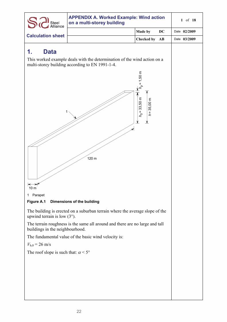
22
APPENDIX A. Worked Example: Wind action on a multi-storey building
1 of 18
Made by DC Date 02/2009
Calculation sheet Checked by AB Date 03/2009
1. Data
This worked example deals with the determination of the wind action on a multi-storey building according to EN 1991-1-4.
10 m
120 m
hh h
p=
1,5
0 m
0=
33
,50
m
= 3
5,0
0 m
1
1 Parapet
Figure A.1 Dimensions of the building
The building is erected on a suburban terrain where the average slope of the upwind terrain is low (3°).
The terrain roughness is the same all around and there are no large and tall buildings in the neighbourhood.
The fundamental value of the basic wind velocity is:
Vb,0 = 26 m/s
The roof slope is such that: < 5°
Title Appendix A Worked Example: Wind action on a multi-storey building 2 of 18
3 - 23
2. Peak velocity pressure
2.1. General
For a multi-storey building, the peak velocity pressure generally depends on the wind direction because the height of the building is higher than the width of the upwind face. Therefore we have to distinguish between:
Wind on the long side
Wind on the gable
The calculation of the peak velocity pressure is performed according to the detailed procedure described in Section 7.2.1 of Single-storey steel buildings. Part 3: Actions[10]
.
2.2. Wind on the long side
1 Fundamental value of the basic wind velocity
vb,0 = 26 m/s
2 Basic wind velocity
vb = cdir cseason vb,0
EN 1991-1-4 § 4.2(2)
For cdir and cseason, the recommended values are:
cdir = 1,0
cseason = 1,0
Then: vb = vb,0 = 26 m/s
3 Basic velocity pressure
2bb 2
1vq
where:
= 1,25 kg/m3
EN 1991-1-4 § 4.5(1)
Then: qb = 0,5 × 1,25 × 262 = 422,5 N/m2
4 Terrain factor
kr = 0,19 (z0 / z0,II)0,07
The terrain category is III. Then:
z0 = 0,3 m (and zmin = 5 m)
z0,II = 0,05 m
Then: kr = 0,19 × (0,3 / 0,05)0,07 = 0,215
EN 1991-1-4 § 4.3.2(1)
5 Roughness factor
cr(z) = kr ln(z/z0) for: zmin ≤ z ≤ zmax
cr(z) = cr(zmin) for: z ≤ zmin
EN 1991-1-4 § 4.3.2
Title Appendix A Worked Example: Wind action on a multi-storey building 3 of 18
3 - 24
where:
zmax = 200 m
z is the reference height
The total height of the building is: h = 35 m
The width of the wall is: b = 120 m
h ≤ b therefore qp(z) = qp(ze) with: ze = h = 35 m
Therefore cr(z) = 0,215 × ln(35/0,3) = 1,023
EN 1991-1-4 Figure 7.4
6 Orography factor
Since the slope of the terrain is lower than 3°, the recommended value is used:
co(z) = 1,0
EN 1991-1-4 § 4.3.3
7 Turbulence factor
The recommended value is used:
kl = 1,0
EN 1991-1-4 § 4.4(1)
8 Peak velocity pressure
qp(z) = [1 + 7 Iv(z)] × 0,5 vm2(z)
EN 1991-1-4 § 4.5(1)
where:
= 1,25 kg/m3 (recommended value)
vm(z) is the mean wind velocity at height z above the terrain
vm(z) = cr(z) co(z) vb
= 1,023 × 1,0 × 26
= 26,6 m/s
Iv(z) is the turbulence intensity
Iv(z) = kl / [c0(z) ln(z/z0) ] for: zmin ≤ z ≤ zmax
Iv(z) = Iv(zmin) for: z ≤ zmin
Then: Iv(z) = 1,0 / [1,0 × ln(35/0,3)] = 0,21
qp(z) = [1 + 7 × 0,21] × 0,5 × 1,25 × 26,62 × 10-3
= 1,09 kN/m2
2.3. Wind on the gable
Several parameters are identical to the case of wind on the long side, as follows:
1 Fundamental value of the basic wind velocity
vb,0 = 26 m/s
2 Basic wind velocity
vb = 26 m/s
EN 1991-1-4 § 4.2(2)
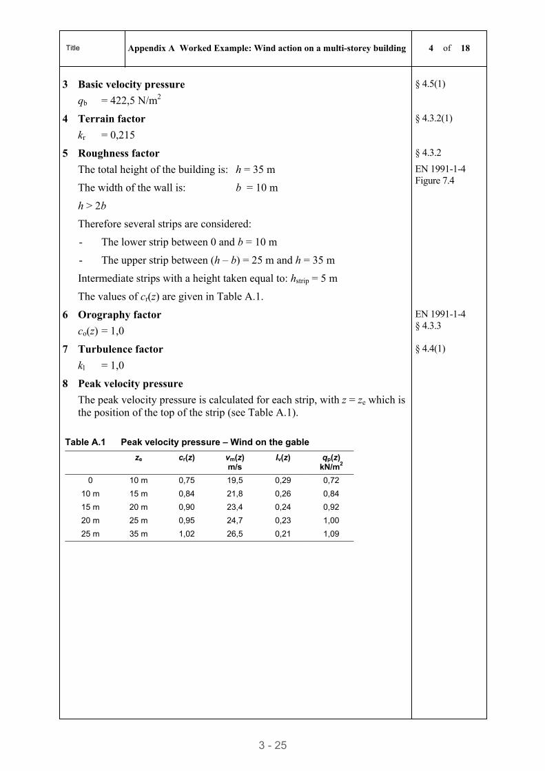
Title Appendix A Worked Example: Wind action on a multi-storey building 4 of 18
3 - 25
3 Basic velocity pressure
qb = 422,5 N/m2
§ 4.5(1)
4 Terrain factor
kr = 0,215
§ 4.3.2(1)
5 Roughness factor § 4.3.2
The total height of the building is: h = 35 m
The width of the wall is: b = 10 m
h > 2b
Therefore several strips are considered:
- The lower strip between 0 and b = 10 m
- The upper strip between (h – b) = 25 m and h = 35 m
Intermediate strips with a height taken equal to: hstrip = 5 m
The values of cr(z) are given in Table A.1.
EN 1991-1-4 Figure 7.4
6 Orography factor
co(z) = 1,0
EN 1991-1-4 § 4.3.3
7 Turbulence factor
kl = 1,0
§ 4.4(1)
8 Peak velocity pressure
The peak velocity pressure is calculated for each strip, with z = ze which is the position of the top of the strip (see Table A.1).
Table A.1 Peak velocity pressure – Wind on the gable
ze cr(z) vm(z) m/s
Iv(z) qp(z) kN/m2
0 10 m 0,75 19,5 0,29 0,72
10 m 15 m 0,84 21,8 0,26 0,84
15 m 20 m 0,90 23,4 0,24 0,92
20 m 25 m 0,95 24,7 0,23 1,00
25 m 35 m 1,02 26,5 0,21 1,09
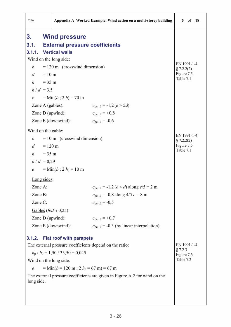
Title Appendix A Worked Example: Wind action on a multi-storey building 5 of 18
3 - 26
3. Wind pressure 3.1. External pressure coefficients 3.1.1. Vertical walls
Wind on the long side:
b = 120 m (crosswind dimension)
d = 10 m
h = 35 m
h / d = 3,5
e = Min(b ; 2 h) = 70 m
EN 1991-1-4 § 7.2.2(2) Figure 7.5 Table 7.1
Zone A (gables): cpe,10 = -1,2 (e > 5d)
Zone D (upwind): cpe,10 = +0,8
Zone E (downwind): cpe,10 = -0,6
Wind on the gable:
b = 10 m (crosswind dimension)
d = 120 m
h = 35 m
h / d = 0,29
e = Min(b ; 2 h) = 10 m
EN 1991-1-4 § 7.2.2(2) Figure 7.5 Table 7.1
Long sides:
Zone A: cpe,10 = -1,2 (e < d) along e/5 = 2 m
Zone B: cpe,10 = -0,8 along 4/5 e = 8 m
Zone C: cpe,10 = -0,5
Gables (h/d 0,25):
Zone D (upwind): cpe,10 = +0,7
Zone E (downwind): cpe,10 = -0,3 (by linear interpolation)
3.1.2. Flat roof with parapets
The external pressure coefficients depend on the ratio:
hp / h0 = 1,50 / 33,50 = 0,045
Wind on the long side:
e = Min(b = 120 m ; 2 h0 = 67 m) = 67 m
The external pressure coefficients are given in Figure A.2 for wind on the long side.
EN 1991-1-4 § 7.2.3 Figure 7.6 Table 7.2
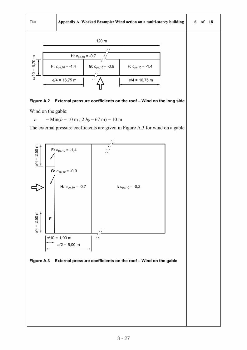
Title Appendix A Worked Example: Wind action on a multi-storey building 6 of 18
3 - 27
e/4 = 16,75 m e/10
= 6
,70
m
F: cpe,10 = -1,4
e/4 = 16,75 m
120 m
H: cpe,10 = -0,7
G: cpe,10 = -0,9 F: cpe,10 = -1,4
Figure A.2 External pressure coefficients on the roof – Wind on the long side
Wind on the gable:
e = Min(b = 10 m ; 2 h0 = 67 m) = 10 m
The external pressure coefficients are given in Figure A.3 for wind on a gable.
e/4
= 2
,50
m
H: cpe,10 = -0,7
F: cpe,10 = -1,4
I: cpe,10 = -0,2
F
G: cpe,10 = -0,9
e/10 = 1,00 m
e/2 = 5,00 m
e/4
= 2
,50
m
Figure A.3 External pressure coefficients on the roof – Wind on the gable
Title Appendix A Worked Example: Wind action on a multi-storey building 7 of 18
3 - 28
3.2. Structural factor
3.2.1. General
The structural factor cscd is calculated from the following equation, for wind on the long side and for wind on the gable:
)( 7 1
. )( 2 1
sv
22svp
ds zI
RBzIkcc
The calculation is performed according to the procedure given in Section 8.2 of this guide.
EN 1991-1-4 § 6.3.1
3.2.2. Wind on the long side
Dimensions: b = 120 m and h = 35 m
1 The terrain category is III.
Then: z0 = 0,30 m and zmin = 5 m
EN 1991-1-4 Table 4.1
2 Reference height:
zs = 0,6 h = 0,6 × 35 = 21 m (> zmin = 5 m)
EN 1991-1-4 Figure 6.1
3 Orography factor
Since the slope of the upwind terrain is less than 3°, c0(zs) = 1,0
EN 1991-1-4 § 4.3.3
4 Roughness factor
Since zmin ≤ zs ≤ zmax (= 200 m)
cr(zs) = 0,19 (z0/z0,II)0,07 ln(zs/z0)
= 0,19 × (0,3 / 0,05)0,07 × ln(21/0,3)
= 0,915
EN 1991-1-4 § 4.3.2
5 Turbulence factor (recommended value):
kl = 1,0
EN 1991-1-4 § 4.4(1)
6 Turbulence intensity
Since zmin ≤ zs ≤ zmax (= 200 m)
Iv(zs) = kl / [c0(zs) ln(zs/z0) ]
= 1,0 / [1,0 × ln(21 / 0,3)]
= 0,235
EN 1991-1-4 § 4.4(1)
7 Turbulent length scale
Since zs > zmin: L(zs) = Lt (zs/zt)
Lt = 300 m
zt = 200 m
= 0,67 + 0,05 ln(z0) = 0,67 + 0,05 ln(0,30) = 0,61
Then: L(zs) = 300 × (21/200)0,61 = 75,9 m
EN 1991-1-4 § B.1(1)
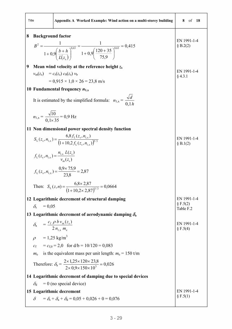
Title Appendix A Worked Example: Wind action on a multi-storey building 8 of 18
3 - 29
8 Background factor
415,0
9,75
351200,9 1
1
0,9 1
1
0,630,63
s
2
zL
hbB
EN 1991-1-4 § B.2(2)
9 Mean wind velocity at the reference height zs
vm(zs) = cr(zs) c0(zs) vb
= 0,915 × 1,0 × 26 = 23,8 m/s
EN 1991-1-4 § 4.3.1
10 Fundamental frequency n1,x
It is estimated by the simplified formula: n1,x = h
d
0,1
n1,x = 350,1
10
= 0,9 Hz
11 Non dimensional power spectral density function
3/5x,1sL
x,1sLx,1sL
),(10,21
),(8,6),(
nzf
nzfnzS
)(
)( ),(
sm
sx,1x,1sL zv
zLnnzf
87,28,23
9,759,0),( x1,sL
nzf
Then:
0664,02,8710,21
87,28,6),(
3/5L
nzS
EN 1991-1-4 § B.1(2)
12 Logarithmic decrement of structural damping
s = 0,05
EN 1991-1-4 § F.5(2) Table F.2
13 Logarithmic decrement of aerodynamic damping a
a = ex1,
smf
2
)(
mn
zvbc
= 1,25 kg/m3
cf = cf,0 = 2,0 for d/b = 10/120 = 0,083
me is the equivalent mass per unit length: me = 150 t/m
Therefore: a = 026,0101509,02
8,2312025,123
EN 1991-1-4 § F.5(4)
14 Logarithmic decrement of damping due to special devices
d = 0 (no special device)
15 Logarithmic decrement
=s + a + d = 0,05 + 0,026 + 0 = 0,076
EN 1991-1-4 § F.5(1)
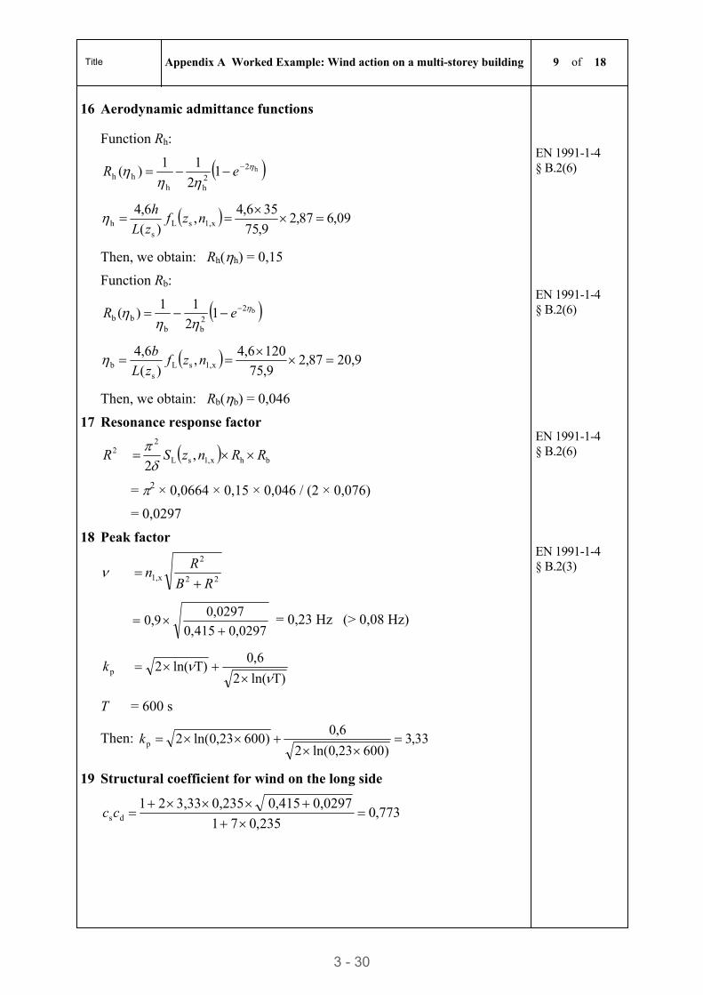
Title Appendix A Worked Example: Wind action on a multi-storey building 9 of 18
3 - 30
16 Aerodynamic admittance functions
Function Rh:
h22hh
hh 12
11)(
eR
09,687,29,75
356,4,
)(
6,4x1,sL
sh
nzf
zL
h
Then, we obtain: Rh(h) = 0,15
EN 1991-1-4 § B.2(6)
Function Rb:
b22bb
bb 12
11)(
eR
9,2087,29,75
1206,4,
)(
6,4x1,sL
sb
nzf
zL
b
Then, we obtain: Rb(b) = 0,046
EN 1991-1-4 § B.2(6)
17 Resonance response factor
2R bhx,1sL
2
,2
RRnzS
= 2 × 0,0664 × 0,15 × 0,046 / (2 × 0,076)
= 0,0297
EN 1991-1-4 § B.2(6)
18 Peak factor
22
2
x1, RB
Rn
0297,0415,0
0297,09,0
= 0,23 Hz (> 0,08 Hz)
T)ln(2
6,0T)ln(2 p
k
T = 600 s
Then: 33,3)600,230ln(2
6,0)600,230ln(2 p
k
EN 1991-1-4 § B.2(3)
19 Structural coefficient for wind on the long side
773,0235,07 1
0,0297 0,415 0,2353,332 1 ds
cc
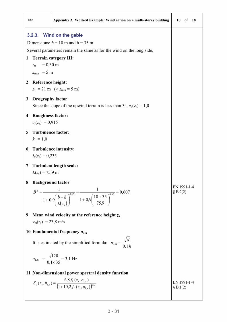
Title Appendix A Worked Example: Wind action on a multi-storey building 10 of 18
3 - 31
3.2.3. Wind on the gable
Dimensions: b = 10 m and h = 35 m
Several parameters remain the same as for the wind on the long side.
1 Terrain category III:
z0 = 0,30 m
zmin = 5 m
2 Reference height:
zs = 21 m (> zmin = 5 m)
3 Orography factor
Since the slope of the upwind terrain is less than 3°, co(zs) = 1,0
4 Roughness factor:
cr(zs) = 0,915
5 Turbulence factor:
kl = 1,0
6 Turbulence intensity:
Iv(zs) = 0,235
7 Turbulent length scale:
L(zs) = 75,9 m
8 Background factor
607,0
9,75
35100,9 1
1
0,9 1
1
0,630,63
s
2
zL
hbB
EN 1991-1-4 § B.2(2)
9 Mean wind velocity at the reference height zs
vm(zs) = 23,8 m/s
10 Fundamental frequency n1,x
It is estimated by the simplified formula: n1,x = h
d
0,1
n1,x = 350,1
120
= 3,1 Hz
11 Non-dimensional power spectral density function
3/5x,1sL
x,1sLx,1sL
),(10,21
),(8,6),(
nzf
nzfnzS
EN 1991-1-4 § B.1(2)
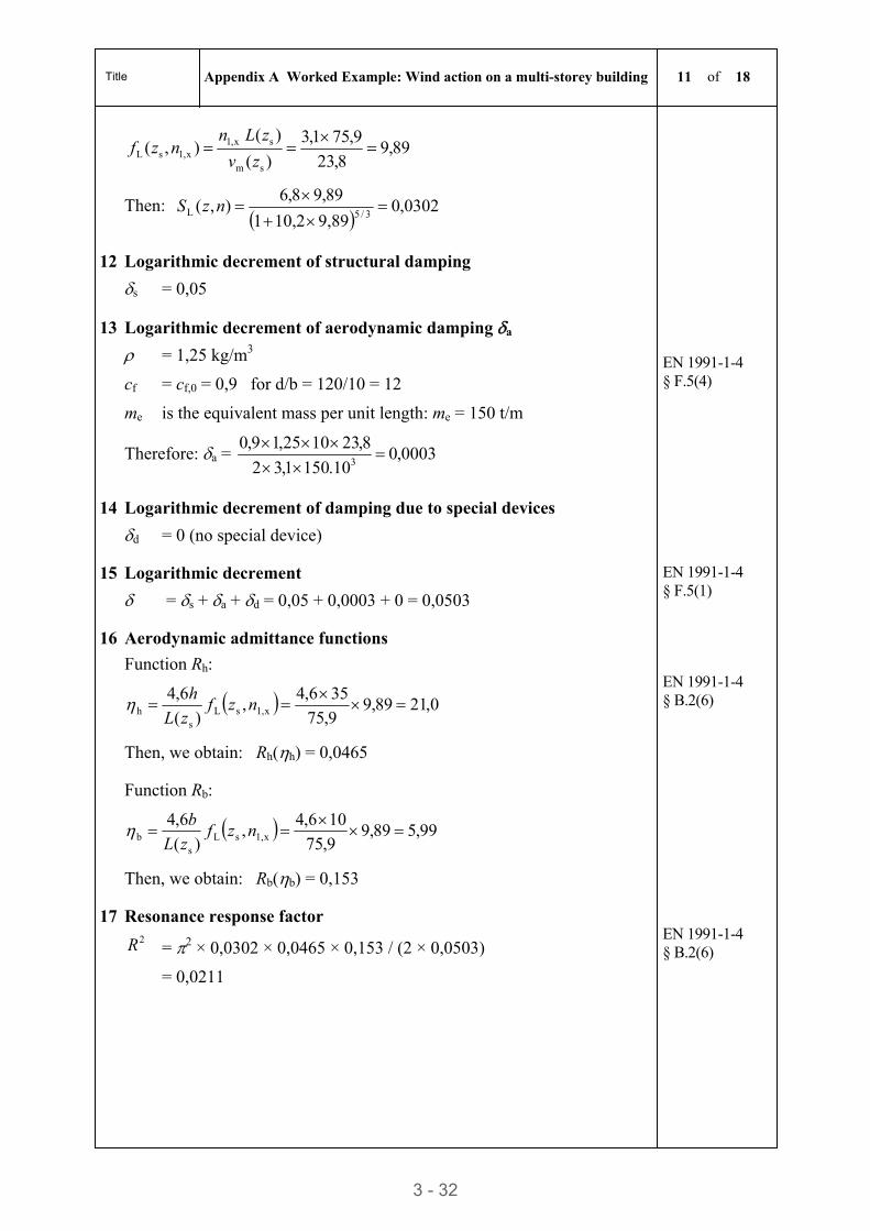
Title Appendix A Worked Example: Wind action on a multi-storey building 11 of 18
3 - 32
89,98,23
9,751,3
)(
)( ),(
sm
sx,1x,1sL
zv
zLnnzf
Then:
0302,09,8910,21
89,98,6),(
3/5L
nzS
12 Logarithmic decrement of structural damping
s = 0,05
13 Logarithmic decrement of aerodynamic damping a
= 1,25 kg/m3
cf = cf,0 = 0,9 for d/b = 120/10 = 12
me is the equivalent mass per unit length: me = 150 t/m
Therefore: a = 0003,010.1501,32
8,231025,19,03
EN 1991-1-4 § F.5(4)
14 Logarithmic decrement of damping due to special devices
d = 0 (no special device)
15 Logarithmic decrement
=s + a + d = 0,05 + 0,0003 + 0 = 0,0503
EN 1991-1-4 § F.5(1)
16 Aerodynamic admittance functions
Function Rh:
0,2189,99,75
356,4,
)(
6,4x1,sL
sh
nzf
zL
h
Then, we obtain: Rh(h) = 0,0465
EN 1991-1-4 § B.2(6)
Function Rb:
99,589,99,75
106,4,
)(
6,4x1,sL
sb
nzf
zL
b
Then, we obtain: Rb(b) = 0,153
17 Resonance response factor 2R = 2 × 0,0302 × 0,0465 × 0,153 / (2 × 0,0503)
= 0,0211
EN 1991-1-4 § B.2(6)
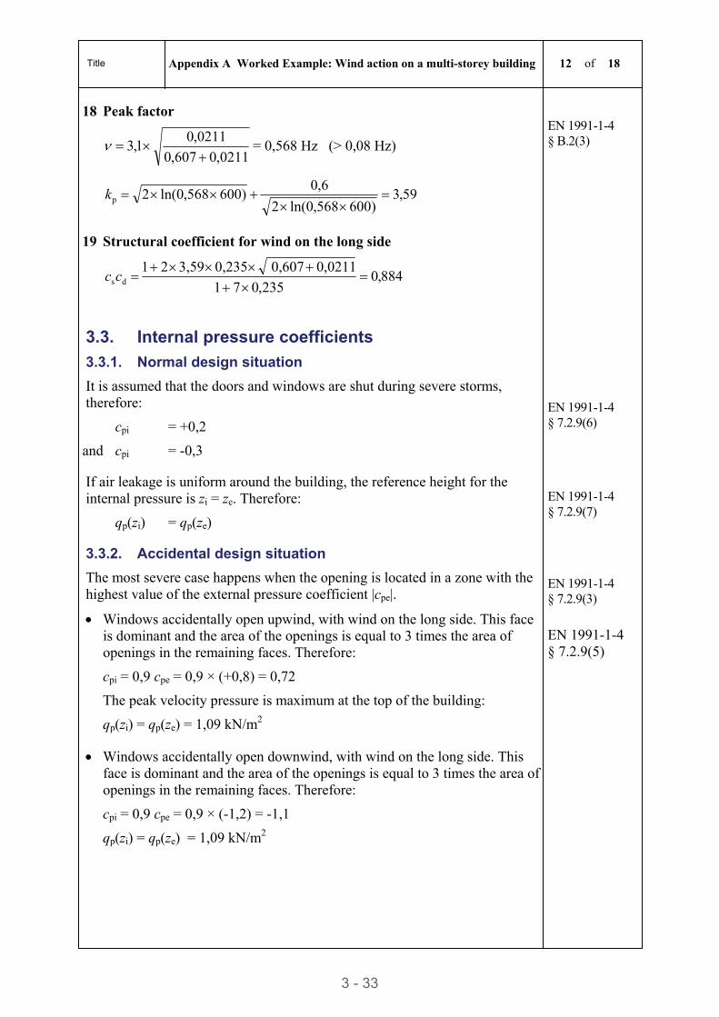
Title Appendix A Worked Example: Wind action on a multi-storey building 12 of 18
3 - 33
18 Peak factor
0211,0607,0
0211,01,3
= 0,568 Hz (> 0,08 Hz)
59,3)600,5680ln(2
6,0)600,5680ln(2 p
k
EN 1991-1-4 § B.2(3)
19 Structural coefficient for wind on the long side
884,0235,07 1
0,0211 0,607 0,2353,592 1 ds
cc
3.3. Internal pressure coefficients
3.3.1. Normal design situation
It is assumed that the doors and windows are shut during severe storms, therefore:
cpi = +0,2
and cpi = -0,3
EN 1991-1-4 § 7.2.9(6)
If air leakage is uniform around the building, the reference height for the internal pressure is zi = ze. Therefore:
qp(zi) = qp(ze)
EN 1991-1-4 § 7.2.9(7)
3.3.2. Accidental design situation
The most severe case happens when the opening is located in a zone with the highest value of the external pressure coefficient |cpe|.
EN 1991-1-4 § 7.2.9(3)
Windows accidentally open upwind, with wind on the long side. This face is dominant and the area of the openings is equal to 3 times the area of openings in the remaining faces. Therefore:
cpi = 0,9 cpe = 0,9 × (+0,8) = 0,72
The peak velocity pressure is maximum at the top of the building:
qp(zi) = qp(ze) = 1,09 kN/m2
EN 1991-1-4 § 7.2.9(5)
Windows accidentally open downwind, with wind on the long side. This face is dominant and the area of the openings is equal to 3 times the area of openings in the remaining faces. Therefore:
cpi = 0,9 cpe = 0,9 × (-1,2) = -1,1
qp(zi) = qp(ze) = 1,09 kN/m2
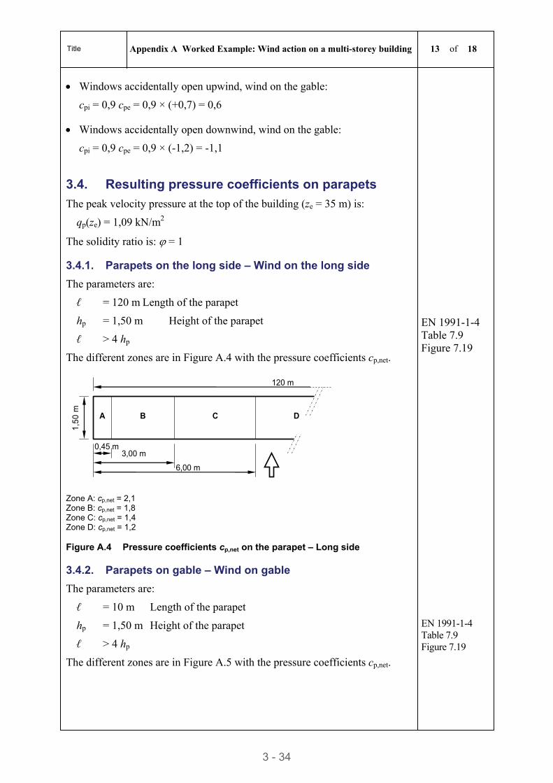
Title Appendix A Worked Example: Wind action on a multi-storey building 13 of 18
3 - 34
Windows accidentally open upwind, wind on the gable:
cpi = 0,9 cpe = 0,9 × (+0,7) = 0,6
Windows accidentally open downwind, wind on the gable:
cpi = 0,9 cpe = 0,9 × (-1,2) = -1,1
3.4. Resulting pressure coefficients on parapets
The peak velocity pressure at the top of the building (ze = 35 m) is:
qp(ze) = 1,09 kN/m2
The solidity ratio is: = 1
3.4.1. Parapets on the long side – Wind on the long side
The parameters are:
ℓ = 120 m Length of the parapet
hp = 1,50 m Height of the parapet
ℓ > 4 hp
The different zones are in Figure A.4 with the pressure coefficients cp,net.
EN 1991-1-4 Table 7.9 Figure 7.19
0,45 m
1,50
m
3,00 m
120 m
6,00 m
A B C D
Zone A: cp,net = 2,1 Zone B: cp,net = 1,8 Zone C: cp,net = 1,4 Zone D: cp,net = 1,2 Figure A.4 Pressure coefficients cp,net on the parapet – Long side
3.4.2. Parapets on gable – Wind on gable
The parameters are:
ℓ = 10 m Length of the parapet
hp = 1,50 m Height of the parapet
ℓ > 4 hp
The different zones are in Figure A.5 with the pressure coefficients cp,net.
EN 1991-1-4 Table 7.9 Figure 7.19
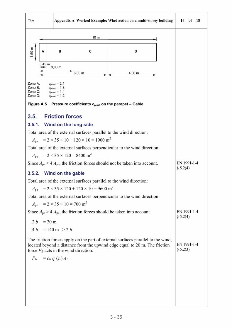
Title Appendix A Worked Example: Wind action on a multi-storey building 14 of 18
3 - 35
0,45 m
1,50
m
3,00 m
10 m
6,00 m
A B C D
4,00 m
Zone A: cp,net = 2,1 Zone B: cp,net = 1,8 Zone C: cp,net = 1,4 Zone D: cp,net = 1,2 Figure A.5 Pressure coefficients cp,net on the parapet – Gable
3.5. Friction forces
3.5.1. Wind on the long side
Total area of the external surfaces parallel to the wind direction:
Apa = 2 × 35 × 10 + 120 × 10 = 1900 m2
Total area of the external surfaces perpendicular to the wind direction:
Ape = 2 × 35 × 120 = 8400 m2
Since Apa < 4 Ape, the friction forces should not be taken into account. EN 1991-1-4 § 5.2(4)
3.5.2. Wind on the gable
Total area of the external surfaces parallel to the wind direction:
Apa = 2 × 35 × 120 + 120 × 10 = 9600 m2
Total area of the external surfaces perpendicular to the wind direction:
Ape = 2 × 35 × 10 = 700 m2
Since Apa > 4 Ape, the friction forces should be taken into account. EN 1991-1-4 § 5.2(4)
2 b = 20 m
4 h = 140 m > 2 b
The friction forces apply on the part of external surfaces parallel to the wind, located beyond a distance from the upwind edge equal to 20 m. The friction force Ffr acts in the wind direction:
Ffr = cfr qp(ze) Afr
EN 1991-1-4 § 5.2(3)
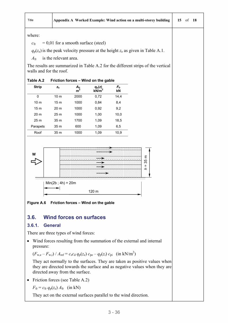
Title Appendix A Worked Example: Wind action on a multi-storey building 15 of 18
3 - 36
where:
cfr = 0,01 for a smooth surface (steel)
qp(ze) is the peak velocity pressure at the height ze as given in Table A.1.
Afr is the relevant area.
The results are summarized in Table A.2 for the different strips of the vertical walls and for the roof.
Table A.2 Friction forces – Wind on the gable
Strip ze Afr m2
qp(z) kN/m2
Ffr kN
0 10 m 2000 0,72 14,4
10 m 15 m 1000 0,84 8,4
15 m 20 m 1000 0,92 9,2
20 m 25 m 1000 1,00 10,0
25 m 35 m 1700 1,09 18,5
Parapets 35 m 600 1,09 6,5
Roof 35 m 1000 1,09 10,9
120 m
h =
35
m
Min(2b ; 4h) = 20m
W
Figure A.6 Friction forces – Wind on the gable
3.6. Wind forces on surfaces
3.6.1. General
There are three types of wind forces:
Wind forces resulting from the summation of the external and internal pressure:
(Fw,e – Fw,i) / Aref = cscd qp(ze) cpe – qp(zi) cpi (in kN/m2)
They act normally to the surfaces. They are taken as positive values when they are directed towards the surface and as negative values when they are directed away from the surface.
Friction forces (see Table A.2)
Ffr = cfr qp(ze) Afr (in kN)
They act on the external surfaces parallel to the wind direction.
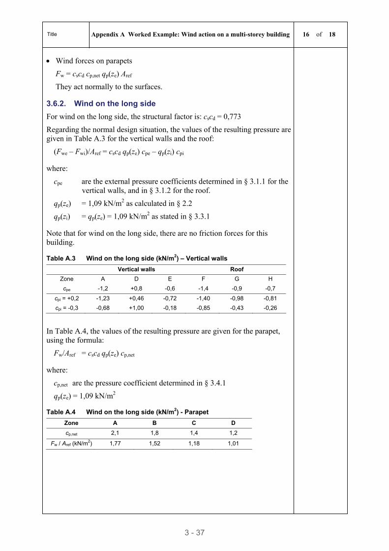
Title Appendix A Worked Example: Wind action on a multi-storey building 16 of 18
3 - 37
Wind forces on parapets
Fw = cscd cp,net qp(ze) Aref
They act normally to the surfaces.
3.6.2. Wind on the long side
For wind on the long side, the structural factor is: cscd = 0,773
Regarding the normal design situation, the values of the resulting pressure are given in Table A.3 for the vertical walls and the roof:
(Fwe – Fwi)/Aref = cscd qp(ze) cpe – qp(zi) cpi
where:
cpe are the external pressure coefficients determined in § 3.1.1 for the vertical walls, and in § 3.1.2 for the roof.
qp(ze) = 1,09 kN/m2 as calculated in § 2.2
qp(zi) = qp(ze) = 1,09 kN/m2 as stated in § 3.3.1
Note that for wind on the long side, there are no friction forces for this building.
Table A.3 Wind on the long side (kN/m2) – Vertical walls
Vertical walls Roof
Zone A D E F G H
cpe -1,2 +0,8 -0,6 -1,4 -0,9 -0,7
cpi = +0,2 -1,23 +0,46 -0,72 -1,40 -0,98 -0,81
cpi = -0,3 -0,68 +1,00 -0,18 -0,85 -0,43 -0,26
In Table A.4, the values of the resulting pressure are given for the parapet, using the formula:
Fw/Aref = cscd qp(ze) cp,net
where:
cp,net are the pressure coefficient determined in § 3.4.1
qp(ze) = 1,09 kN/m2
Table A.4 Wind on the long side (kN/m2) - Parapet
Zone A B C D
cp,net 2,1 1,8 1,4 1,2
Fw / Aref (kN/m2) 1,77 1,52 1,18 1,01
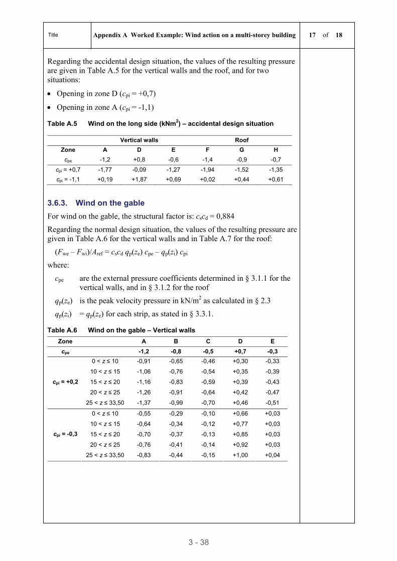
Title Appendix A Worked Example: Wind action on a multi-storey building 17 of 18
3 - 38
Regarding the accidental design situation, the values of the resulting pressure are given in Table A.5 for the vertical walls and the roof, and for two situations:
Opening in zone D (cpi = +0,7)
Opening in zone A (cpi = -1,1)
Table A.5 Wind on the long side (kNm2) – accidental design situation
Vertical walls Roof
Zone A D E F G H
cpe -1,2 +0,8 -0,6 -1,4 -0,9 -0,7
cpi = +0,7 -1,77 -0,09 -1,27 -1,94 -1,52 -1,35
cpi = -1,1 +0,19 +1,87 +0,69 +0,02 +0,44 +0,61
3.6.3. Wind on the gable
For wind on the gable, the structural factor is: cscd = 0,884
Regarding the normal design situation, the values of the resulting pressure are given in Table A.6 for the vertical walls and in Table A.7 for the roof:
(Fwe – Fwi)/Aref = cscd qp(ze) cpe – qp(zi) cpi
where:
cpe are the external pressure coefficients determined in § 3.1.1 for the vertical walls, and in § 3.1.2 for the roof
qp(ze) is the peak velocity pressure in kN/m2 as calculated in § 2.3
qp(zi) = qp(ze) for each strip, as stated in § 3.3.1.
Table A.6 Wind on the gable – Vertical walls
Zone A B C D E
cpe -1,2 -0,8 -0,5 +0,7 -0,3
0 < z ≤ 10 -0,91 -0,65 -0,46 +0,30 -0,33
10 < z ≤ 15 -1,06 -0,76 -0,54 +0,35 -0,39
15 < z ≤ 20 -1,16 -0,83 -0,59 +0,39 -0,43
20 < z ≤ 25 -1,26 -0,91 -0,64 +0,42 -0,47
cpi = +0,2
25 < z ≤ 33,50 -1,37 -0,99 -0,70 +0,46 -0,51
0 < z ≤ 10 -0,55 -0,29 -0,10 +0,66 +0,03
10 < z ≤ 15 -0,64 -0,34 -0,12 +0,77 +0,03
15 < z ≤ 20 -0,70 -0,37 -0,13 +0,85 +0,03
20 < z ≤ 25 -0,76 -0,41 -0,14 +0,92 +0,03
cpi = -0,3
25 < z ≤ 33,50 -0,83 -0,44 -0,15 +1,00 +0,04
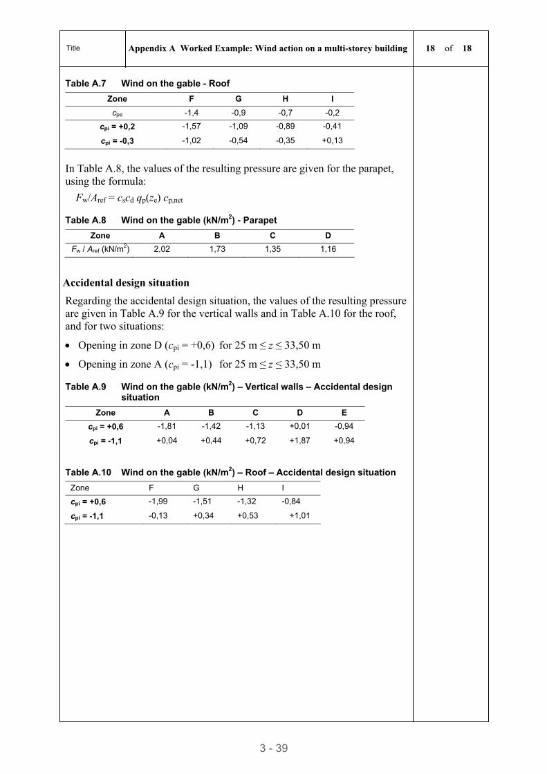
Title Appendix A Worked Example: Wind action on a multi-storey building 18 of 18
3 - 39
Table A.7 Wind on the gable - Roof
Zone F G H I
cpe -1,4 -0,9 -0,7 -0,2
cpi = +0,2 -1,57 -1,09 -0,89 -0,41
cpi = -0,3 -1,02 -0,54 -0,35 +0,13
In Table A.8, the values of the resulting pressure are given for the parapet, using the formula:
Fw/Aref = cscd qp(ze) cp,net
Table A.8 Wind on the gable (kN/m2) - Parapet
Zone A B C D
Fw / Aref (kN/m2) 2,02 1,73 1,35 1,16
Accidental design situation
Regarding the accidental design situation, the values of the resulting pressure are given in Table A.9 for the vertical walls and in Table A.10 for the roof, and for two situations:
Opening in zone D (cpi = +0,6) for 25 m ≤ z ≤ 33,50 m
Opening in zone A (cpi = -1,1) for 25 m ≤ z ≤ 33,50 m
Table A.9 Wind on the gable (kN/m2) – Vertical walls – Accidental design situation
Zone A B C D E
cpi = +0,6 -1,81 -1,42 -1,13 +0,01 -0,94
cpi = -1,1 +0,04 +0,44 +0,72 +1,87 +0,94
Table A.10 Wind on the gable (kN/m2) – Roof – Accidental design situation
Zone F G H I
cpi = +0,6 -1,99 -1,51 -1,32 -0,84
cpi = -1,1 -0,13 +0,34 +0,53 +1,01
STEEL BUILDINGS IN EUROPE
Multi-Storey Steel Buildings
Part 4: Detailed Design

Multi-Storey Steel Buildings
Part 4: Detailed Design

Part 4: Detailed Design
4 – ii

Part 4: Detailed Design
4 – iii
FOREWORD
This publication is part four of the design guide, Multi-Storey Steel Buildings.
The 10 parts in the Multi-Storey Steel Buildings guide are:
Part 1: Architect’s guide
Part 2: Concept design
Part 3: Actions
Part 4: Detailed design
Part 5: Joint design
Part 6: Fire Engineering
Part 7: Model construction specification
Part 8: Design software – section capacity
Part 9: Design software – simple connections
Part 10: Software specification for composite beams.
Multi-Storey Steel Buildings is one of two design guides. The second design guide is Single-Storey Steel Buildings.
The two design guides have been produced in the framework of the European project “Facilitating the market development for sections in industrial halls and low rise buildings (SECHALO) RFS2-CT-2008-0030”.
The design guides have been prepared under the direction of Arcelor Mittal, Peiner Träger and Corus. The technical content has been prepared by CTICM and SCI, collaborating as the Steel Alliance.
Part 4: Detailed Design
4 – iv
Contents Page No
FOREWORD III
SUMMARY VI
1 INTRODUCTION 1 1.1 General 1 1.2 Scope of this document 1
2 BASIC CONCEPTS 2 2.1 Introduction 2 2.2 Simple construction 2 2.3 Sway and non-sway frames 3 2.4 Second order effects 4 2.5 General design procedure 7 2.6 Design of steel bracing systems to achieve cr 10 for all combinations
of actions 8 2.7 The effects of imperfections 10 2.8 Design summary 14
3 PRACTICAL GLOBAL ANALYSIS FOR ‘SIMPLE CONSTRUCTION’ 15 3.1 Introduction 15 3.2 Actions and their combinations 15 3.3 Analysis for gravity loads 16 3.4 Allowance for second order effects 18 3.5 Design Summary 19
4 SERVICEABILITY LIMIT STATE 20 4.1 General 20 4.2 Load combinations 20 4.3 Horizontal deflection limits 20 4.4 Vertical deflection limits 21 4.5 Precambering 23 4.6 Dynamic response 23 4.7 Design summary 24
5 ULTIMATE LIMIT STATE 25 5.1 Introduction 25 5.2 Floor systems 25 5.3 Columns 37 5.4 Vertical bracing 42 5.5 Horizontal bracing 44 5.6 Design summary 46
6 ROBUSTNESS 47 6.1 Accidental design situations 47 6.2 Consequence classes 48 6.3 Design for the consequences of localised failure in multi-storey buildings 49 6.4 Key elements 53 6.5 Risk assessment 54 6.6 Design summary 54
REFERENCES 55
APPENDIX A WORKED EXAMPLES 56 A.1 Worked Example – Simply supported, laterally unrestrained beam 57
Part 4: Detailed Design
4 – v
A.2 Worked Example – Simply supported beam with intermediate lateral restraints 64
A.3 Worked Example – Simply supported, secondary composite beam 71 A.4 Worked Example – Simply supported, primary composite beam 81 A.5 Worked Example – Pinned column using non-slender H sections 94 A.6 Worked Example – Bolted connection of an angle brace in tension to a
gusset 98
Part 4: Detailed Design
4 – vi
SUMMARY
This document is the fourth part of a publication covering all aspects of medium rise multi-storey building design. The guide focuses on the detailed design of buildings that use steel bracing or concrete cores to resist horizontal actions and provide horizontal stability.
The objective of this document is to introduce the basic concepts of multi-storey form of construction, commonly referred to as ‘simple construction’ and to provide guidance on practical aspects of building design.
It provides detailed guidance on how to design for stability, and goes on to give advice on the global analysis of multi-storey buildings.
It also covers the serviceability and ultimate limit state requirements of EN 1993 and EN 1994 and provides guidance on design for robustness to meet the requirements of EN 1991-1-7.
It includes six worked examples, covering common elements in the design of multi-storey buildings.
Part 4: Detailed Design
4 – 1
1 INTRODUCTION
1.1 General In this publication, medium rise steel frames are defined as frames where neither resistance to horizontal loads, nor achieving sufficient sway stability has significant impact on either the plan arrangement of the floors or the overall structural form. This limit is normally regarded as twelve storeys.
Low rise buildings (of two or three storeys) are only subject to modest horizontal forces and may readily be conceived with robust bracing systems such that second order effects are minimised, to the extent that sway stability effects need not be considered explicitly in design. The bracing may be provided either by triangulated bracing or by reinforced concrete core(s); the floors act as diaphragms to tie all columns into the bracing or cores.
1.2 Scope of this document This document guides the designer through all the steps involved in the detailed design of braced multi-storey frames to EN 1993[1] and EN 1994[2].
It focuses on the application of ‘simple construction’ as the way of achieving the most economic form of construction. Coincidently, and very conveniently, these approaches also are the simplest to use in the design office, thereby minimising design office costs.
The guide addresses:
The basic concept of simple construction
Guidance on the global analysis of frames for simple construction
Design checks at the Serviceability Limit State (SLS)
Design checks for the Ultimate Limit State (ULS): floor systems, columns, vertical and horizontal bracing
Checks to ensure the structure has sufficient robustness to resist both specified and unspecified accidental loads.
Part 4: Detailed Design
4 – 2
2 BASIC CONCEPTS
2.1 Introduction EN 1993-1-1[1] provides a very flexible, comprehensive framework for the global analysis and design of a wide range of steel frames.
This section introduces the basic concepts that underpin the design approaches for economic low and medium-rise multi-storey frames.
2.2 Simple construction As discussed in Multi-storey steel buildings. Part 2: Concept design[3], the greatest economy for low and medium rise braced multi-storey frames will be achieved by the use of ‘simple construction’. The analysis assumes nominally pinned connections between beams and columns; resistance to horizontal forces is provided by bracing systems or concrete cores. Consequently, the beams are designed as simply supported and the columns are designed only for any moments arising from nominal eccentricities of connections of the beams to the columns (in conjunction with the axial forces). As a further consequence, it is not necessary to consider pattern loading to derive design forces in the columns.
This design approach is accommodated by the EN 1993[1] ‘simple’ joint model, in which the joint may be assumed not to transmit bending moments. This approach may be used if the joint is classified as ‘nominally pinned’ according to EN 1993-1-8, § 5.2.2. This classification may be based on previous satisfactory performance in similar cases. The joint configurations discussed in Section 3.3 assume a pinned connection and that the beam reactions are applied eccentrically to the columns. The widespread and successful use of these types of connection in many parts of Europe provide the evidence of satisfactory performance required by EN 1993-1-8, § 5.2.2.
For braced frames designed in accordance with EN 1993-1-1[1], the global analysis model may therefore assume pinned connections between the columns and the beams, provided that the columns are designed for any bending moments due to eccentric reactions from the beams (see Section 3.3).
Part 4: Detailed Design
4 – 3
(a) fin plate (b) flexible end plate (c) web cleats
Figure 2.1 Typical ‘simple’ beam to column connections
For such simple frames, it is almost always economic to use:
HE sections for columns
IPE sections for beams
Flats, angles or hollow sections for diagonal bracing members.
Figure 2.1 shows typical beam to column connections.
2.3 Sway and non-sway frames 2.3.1 Definitions
A braced frame has sufficient structural components to transmit horizontal forces directly to the foundations. These components provide stability to the frame. They may be one or more concrete cores, which will usually contain the vertical services, lifts and stairs. Alternatively, they may be complete systems of triangulated steel members in vertical planes (acting in conjunction with floor diaphragms or horizontal bracing).
In a braced frame, the beams are designed as simply supported. The columns carry axial loads and (generally) minimal moments. The beam to column connections are designed as nominally pinned, and hence not attracting any moment; sufficient rotation capacity must be provided.
An unbraced frame is any frame which does not have either a concrete core or a complete system of vertical triangulation. At least some beam to column connections must be moment resisting in order to transmit horizontal forces to the foundations and to provide frame stability.
It should be noted that horizontal structure and associated behaviour needs to be considered separately in two, usually orthogonal, directions. Thus a frame may be:
Braced in both directions
Braced in one direction and unbraced in the other
Unbraced in both directions
Part 4: Detailed Design
4 – 4
A ‘sway-sensitive frame’ is a frame where horizontal flexibility is such that there needs to be some allowance for the effects of deformed geometry.
A ‘sway-insensitive frame’ is a frame with sufficient horizontal stiffness that second order effects may be ignored.
It should be noted that horizontal stiffness needs to be considered separately in two, usually orthogonal, directions. Thus, a frame may be:
A sway-sensitive frame in both directions
A sway-sensitive frame in one direction and a sway-insensitive frame in the other
A sway-insensitive frame in both directions.
2.3.2 Distinction between sway/non-sway and unbraced/braced concepts
Both sway-sensitivity and braced/unbraced concepts relate to horizontal structure. However, they are essentially different.
Sway-sensitivity definitions entirely relate to horizontal stiffness and behaviour.
Braced/unbraced are descriptions of structural arrangement.
It follows that, in each of the two orthogonal planes, a frame may be:
Braced and sway-insensitive
Braced and sway-sensitive
Unbraced and sway-sensitive
Unbraced but sway-insensitive (unusual, but possible).
2.4 Second order effects 2.4.1 Basic principles
The sensitivity of any frame to second order effects may be illustrated simply by considering one ‘bay’ of a multi-storey building in simple construction (i.e. with pinned connections between beams and columns); the bay is restrained laterally by a spring representing the bracing system. First and second order displacements are illustrated in Figure 2.2.
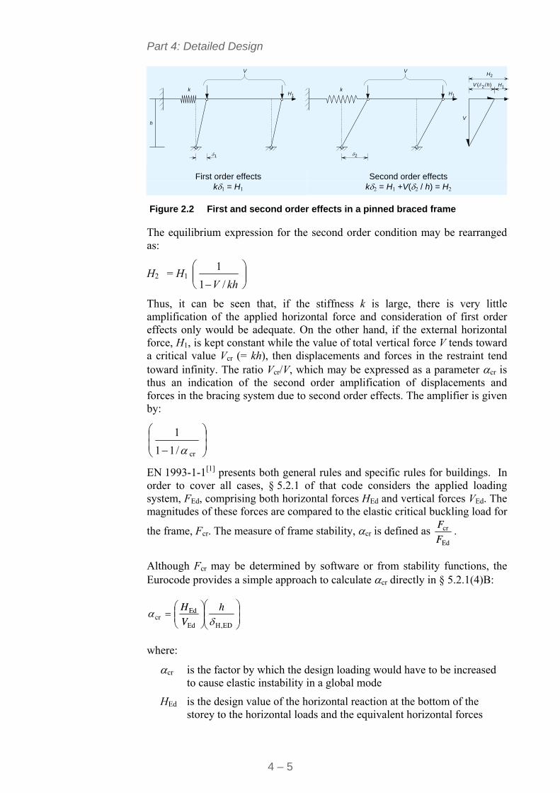
Part 4: Detailed Design
4 – 5
V V
V
Vkk
h
1
1 1H H
H
2
2
2( /h) H1
First order effects k1 = H1
Second order effects k2 = H1 +V(2 / h) = H2
Figure 2.2 First and second order effects in a pinned braced frame
The equilibrium expression for the second order condition may be rearranged as:
H2 = H1
khV /1
1
Thus, it can be seen that, if the stiffness k is large, there is very little amplification of the applied horizontal force and consideration of first order effects only would be adequate. On the other hand, if the external horizontal force, H1, is kept constant while the value of total vertical force V tends toward a critical value Vcr (= kh), then displacements and forces in the restraint tend toward infinity. The ratio Vcr/V, which may be expressed as a parameter cr is thus an indication of the second order amplification of displacements and forces in the bracing system due to second order effects. The amplifier is given by:
cr/11
1
EN 1993-1-1[1] presents both general rules and specific rules for buildings. In order to cover all cases, § 5.2.1 of that code considers the applied loading system, FEd, comprising both horizontal forces HEd and vertical forces VEd. The magnitudes of these forces are compared to the elastic critical buckling load for
the frame, Fcr. The measure of frame stability, cr is defined as Ed
cr
FF
.
Although Fcr may be determined by software or from stability functions, the Eurocode provides a simple approach to calculate cr directly in § 5.2.1(4)B:
EDH,Ed
Edcr
hVH
where:
cr is the factor by which the design loading would have to be increased to cause elastic instability in a global mode
HEd is the design value of the horizontal reaction at the bottom of the storey to the horizontal loads and the equivalent horizontal forces
Part 4: Detailed Design
4 – 6
VEd is the total design vertical load on the structure on the bottom of the storey
H,Ed is the horizontal displacement at the top of the storey, relative to the bottom of the storey, under the horizontal loads (both externally applied and equivalent horizontal forces)
h is the storey height.
2.4.2 Allowance for second order effects
As discussed in Section 2.3.1, horizontal flexibility influences overall structural stability and the significance of second order effects on overall design.
As described in Section 2.4.1, EN 1993-1-1 § 5.2.1 introduces the concept of cr as the basic measure of horizontal flexibility and its influence on structural stability.
Depending on the value of c, three alternative design situations are possible.
cr > 10
Where horizontal stability is provided by a concrete core, or by robust bracing, calculations will generally demonstrate that cr > 10 for all combinations of actions. EN 1993-1-1, § 5.2.1(3) permits the use of first order analysis for such frames.
When cr > 10, second order effects are considered small enough to be ignored.
It may be convenient for certain low rise frames to ensure that cr > 10, by providing bracing of sufficient strength and stiffness. This is discussed in Section 2.6. For medium rise structures, this simple approach will usually lead to heavy triangulated bracing with large and expensive connections.
3,0 < cr < 10
For buildings between three and ten storeys, bracing designed for strength will generally lead to 3,0 < cr < 10. (If cr should fall below 3,0 it is usually practical to increase bracing sizes to satisfy this lower limit).
For cr > 3,0 EN 1993-1-1, § 5.2.2(6)B permits the use of first order analysis provided that all storeys a similar:
distribution of vertical loads and
distribution of horizontal loads and
distribution of frame stiffness with respect to the applied storey shear forces.
To allow for second order effects, all relevant action effects are amplified by the factor
cr
11
1
Part 4: Detailed Design
4 – 7
Relevant action effects are:
Externally applied horizontal loads, e.g. wind, HEd
Equivalent horizontal forces (EHF) used to allow for frame imperfections, VEd
Other possible sway effects. (These are rare in low rise multi-storey frames but could occur, for example where the building is on a sloping site with differing levels of foundations. In such circumstances, axial shortening of the different lengths of columns will cause overall sway.)
cr < 3.0
For cr < 3.0, EN 1993-1-1, § 5.2.2 requires such structures to be analysed by second order analysis. This approach is not recommended for low or medium rise buildings. Second order analysis may lead to marginal economies in the mass of bracing systems but this advantage is more than offset by the increased design costs and the difficulty of optimising such structures. Such flexible structures are anyway likely to fail horizontal serviceability criteria.
2.5 General design procedure Unless the simple approach described in Section 2.6 for low rise buildings is adopted, the general design process is as follows:
1. Determine the ULS vertical actions.
2. Calculate the equivalent horizontal forces (EHF) to allow for imperfections (see Section 2.7.1 of this guide).
3. Determine the ULS horizontal loads.
4. Determine the total horizontal loads (from 2 and 3 above).
5. Choose bracing configuration and choose bracing members, based on the total horizontal loads.
(Note that the wind forces and EHF are usually distributed to individual braced bays by simple load allocation techniques, thus avoiding the need for a three-dimensional analysis).
6. Carry out first order analysis of the braced frames to determine both the forces in the bracing system and the sway stiffness of the frames.
(This two dimensional analysis of each vertical bracing system is usually carried out by computer to provide ready access to displacements).
7. For each floor of each braced bay, determine the ‘local’ cr from:
cr = EdH,Ed
Ed
h
VH
8. Determine the governing cr as the lowest value obtained from the analysis above.
9. If cr > 10, second order effects are small enough to be ignored. If 3,0 < cr < 10, calculate the amplification factor and increase all relevant action effects (the bracing may need to be re-designed).
Part 4: Detailed Design
4 – 8
If cr < 3,0 the recommended approach is to increase the stiffness of the structure.
2.6 Design of steel bracing systems to achieve cr 10 for all combinations of actions
2.6.1 Introduction
Vertical bracing is designed to resist wind load plus equivalent horizontal forces given by EN 1993-1-1, § 5.3. First order frame analysis can be used for braced frames, provided that the vertical bracing provides sufficient stiffness. For first order analysis to be applicable, EN 1993-1-1, § 5.2.1 requires that cr 10 for the whole frame and therefore for each storey of a multi-storey building.
Simple guidance is given below for the selection of bracing members so that sufficient stiffness is provided for such analysis to be valid. This allows the designer to avoid either the complexities of second order analysis, or of allowing for second order effects by amplification of first order effects. The method also permits the design of the frame to be undertaken without any recourse to computer analysis (such analysis is normally necessary in order to determine horizontal displacements and hence, cr).
The parametric study that led to these design recommendations is presented in Access Steel document SN028a-EN-EU[4].
The bracing arrangements considered by this study are presented in Figure 2.3.
2.6.2 Scope
The design procedure presented below was derived for buildings with the following limitations:
Height not exceeding 30 m
Angle of bracing members between 15° and 50° to the horizontal
The bracing arrangements are as shown in Figure 2.3
Note that the procedure does not depend on the steel grade.
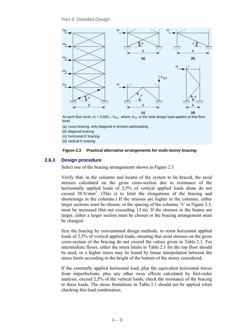
Part 4: Detailed Design
4 – 9
1
4
3
5
2
H H
H
F
H
H
H
H
H
H
b b
b bb
Ed
(a) (b)
(c) (d)
At each floor level, Hi = 0,025 VEd,i where VEd,i is the total design load applied at that floor level
(a) cross bracing, only diagonal in tension participating (b) diagonal bracing (c) horizontal K bracing (d) vertical K bracing
Figure 2.3 Practical alternative arrangements for multi-storey bracing:
2.6.3 Design procedure
Select one of the bracing arrangements shown in Figure 2.3.
Verify that, in the columns and beams of the system to be braced, the axial stresses calculated on the gross cross-section due to resistance of the horizontally applied loads of 2,5% of vertical applied loads alone do not exceed 30 N/mm2. (This is to limit the elongations of the bracing and shortenings in the columns.) If the stresses are higher in the columns, either larger sections must be chosen, or the spacing of the columns ‘b’ in Figure 2.3, must be increased (but not exceeding 12 m). If the stresses in the beams are larger, either a larger section must be chosen or the bracing arrangement must be changed.
Size the bracing by conventional design methods, to resist horizontal applied loads of 2,5% of vertical applied loads, ensuring that axial stresses on the gross cross-section of the bracing do not exceed the values given in Table 2.1. For intermediate floors, either the stress limits in Table 2.1 for the top floor should be used, or a higher stress may be found by linear interpolation between the stress limits according to the height of the bottom of the storey considered.
If the externally applied horizontal load, plus the equivalent horizontal forces from imperfections, plus any other sway effects calculated by first-order analysis, exceed 2,5% of the vertical loads, check the resistance of the bracing to these loads. The stress limitations in Table 2.1 should not be applied when checking this load combination.
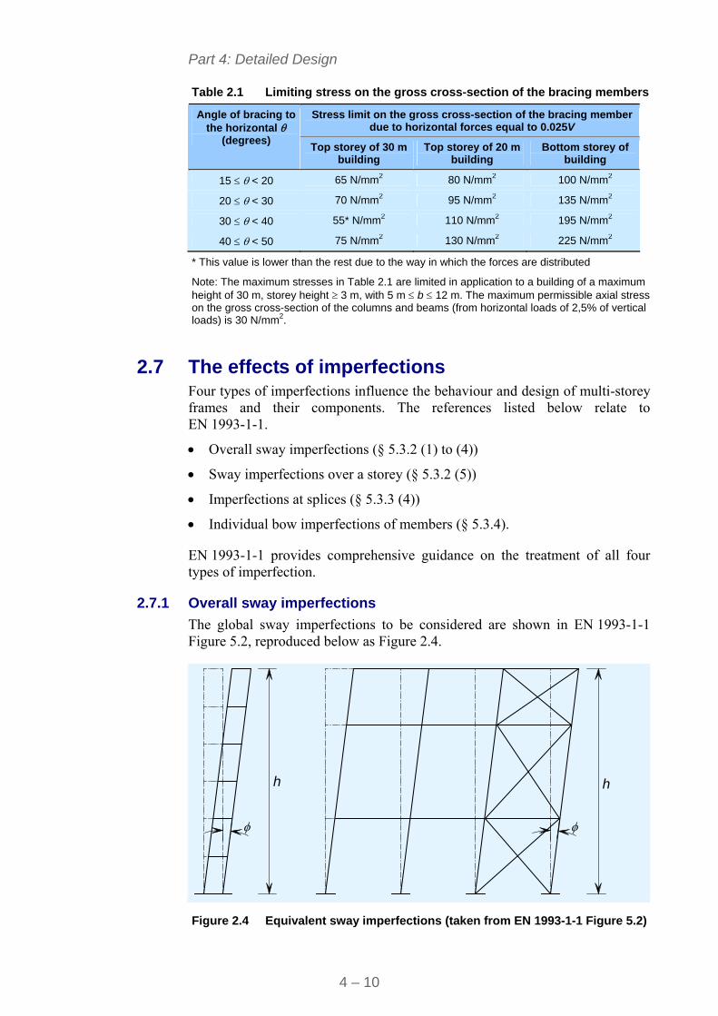
Part 4: Detailed Design
4 – 10
Table 2.1 Limiting stress on the gross cross-section of the bracing members
Stress limit on the gross cross-section of the bracing member due to horizontal forces equal to 0.025V
Angle of bracing to the horizontal
(degrees) Top storey of 30 m
building Top storey of 20 m
building Bottom storey of
building
15 < 20 65 N/mm2 80 N/mm2 100 N/mm2
20 < 30 70 N/mm2 95 N/mm2 135 N/mm2
30 < 40 55* N/mm2 110 N/mm2 195 N/mm2
40 < 50 75 N/mm2 130 N/mm2 225 N/mm2
* This value is lower than the rest due to the way in which the forces are distributed
Note: The maximum stresses in Table 2.1 are limited in application to a building of a maximum height of 30 m, storey height 3 m, with 5 m b 12 m. The maximum permissible axial stress on the gross cross-section of the columns and beams (from horizontal loads of 2,5% of vertical loads) is 30 N/mm2.
2.7 The effects of imperfections Four types of imperfections influence the behaviour and design of multi-storey frames and their components. The references listed below relate to EN 1993-1-1.
Overall sway imperfections (§ 5.3.2 (1) to (4))
Sway imperfections over a storey (§ 5.3.2 (5))
Imperfections at splices (§ 5.3.3 (4))
Individual bow imperfections of members (§ 5.3.4).
EN 1993-1-1 provides comprehensive guidance on the treatment of all four types of imperfection.
2.7.1 Overall sway imperfections
The global sway imperfections to be considered are shown in EN 1993-1-1 Figure 5.2, reproduced below as Figure 2.4.
h h
Figure 2.4 Equivalent sway imperfections (taken from EN 1993-1-1 Figure 5.2)
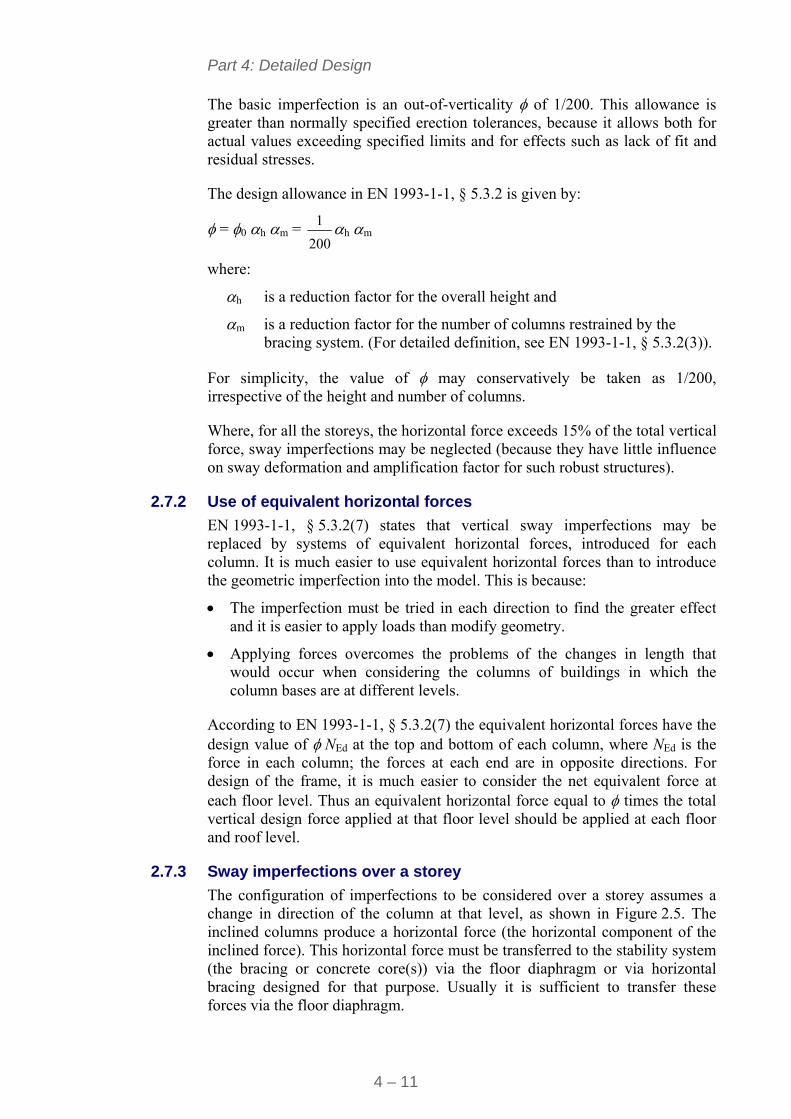
Part 4: Detailed Design
4 – 11
The basic imperfection is an out-of-verticality of 1/200. This allowance is greater than normally specified erection tolerances, because it allows both for actual values exceeding specified limits and for effects such as lack of fit and residual stresses.
The design allowance in EN 1993-1-1, § 5.3.2 is given by:
= 0 h m = 200
1 h m
where:
h is a reduction factor for the overall height and
m is a reduction factor for the number of columns restrained by the bracing system. (For detailed definition, see EN 1993-1-1, § 5.3.2(3)).
For simplicity, the value of may conservatively be taken as 1/200, irrespective of the height and number of columns.
Where, for all the storeys, the horizontal force exceeds 15% of the total vertical force, sway imperfections may be neglected (because they have little influence on sway deformation and amplification factor for such robust structures).
2.7.2 Use of equivalent horizontal forces
EN 1993-1-1, § 5.3.2(7) states that vertical sway imperfections may be replaced by systems of equivalent horizontal forces, introduced for each column. It is much easier to use equivalent horizontal forces than to introduce the geometric imperfection into the model. This is because:
The imperfection must be tried in each direction to find the greater effect and it is easier to apply loads than modify geometry.
Applying forces overcomes the problems of the changes in length that would occur when considering the columns of buildings in which the column bases are at different levels.
According to EN 1993-1-1, § 5.3.2(7) the equivalent horizontal forces have the design value of NEd at the top and bottom of each column, where NEd is the force in each column; the forces at each end are in opposite directions. For design of the frame, it is much easier to consider the net equivalent force at each floor level. Thus an equivalent horizontal force equal to times the total vertical design force applied at that floor level should be applied at each floor and roof level.
2.7.3 Sway imperfections over a storey
The configuration of imperfections to be considered over a storey assumes a change in direction of the column at that level, as shown in Figure 2.5. The inclined columns produce a horizontal force (the horizontal component of the inclined force). This horizontal force must be transferred to the stability system (the bracing or concrete core(s)) via the floor diaphragm or via horizontal bracing designed for that purpose. Usually it is sufficient to transfer these forces via the floor diaphragm.
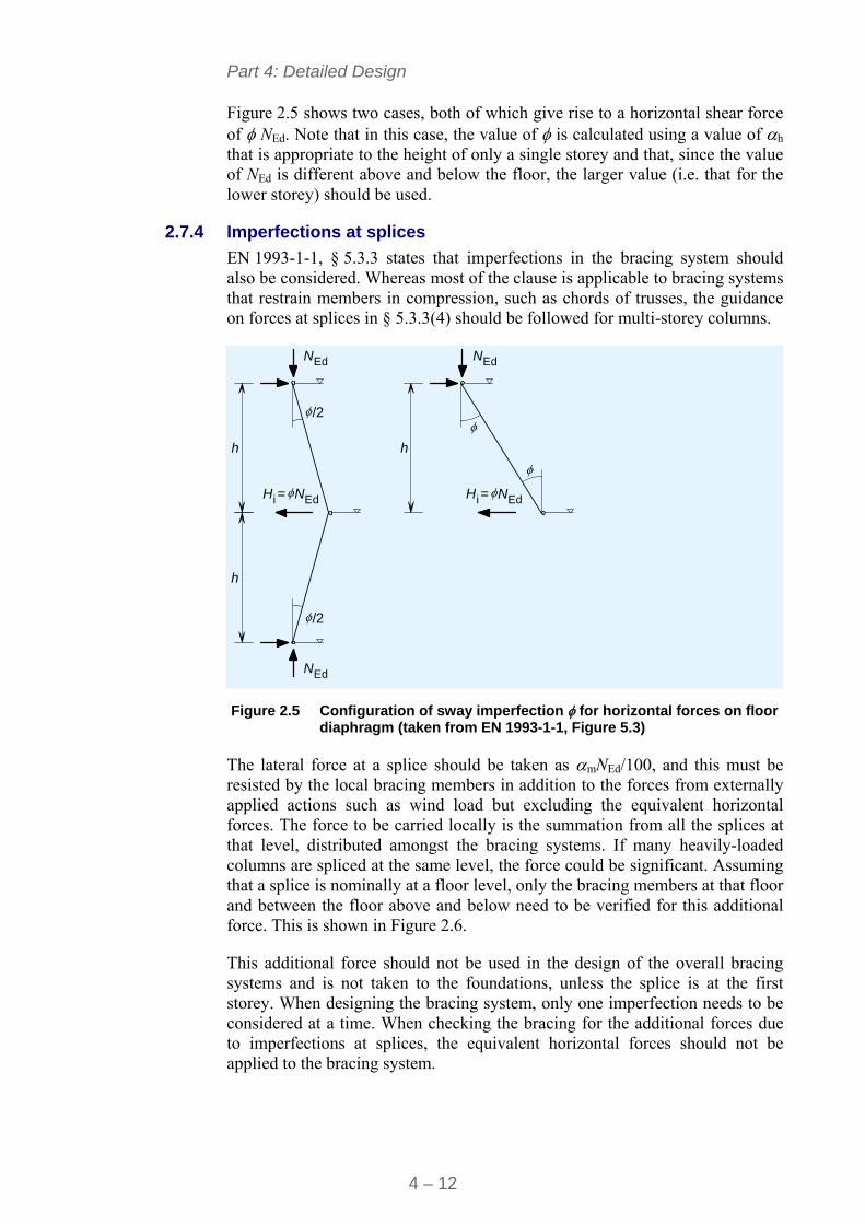
Part 4: Detailed Design
4 – 12
Figure 2.5 shows two cases, both of which give rise to a horizontal shear force of NEd. Note that in this case, the value of is calculated using a value of h that is appropriate to the height of only a single storey and that, since the value of NEd is different above and below the floor, the larger value (i.e. that for the lower storey) should be used.
2.7.4 Imperfections at splices
EN 1993-1-1, § 5.3.3 states that imperfections in the bracing system should also be considered. Whereas most of the clause is applicable to bracing systems that restrain members in compression, such as chords of trusses, the guidance on forces at splices in § 5.3.3(4) should be followed for multi-storey columns.
h
h h
N
N N
N N
Ed
Ed Ed
Ed Ed
= =H Hi i
/2
/2
Figure 2.5 Configuration of sway imperfection for horizontal forces on floor diaphragm (taken from EN 1993-1-1, Figure 5.3)
The lateral force at a splice should be taken as mNEd/100, and this must be resisted by the local bracing members in addition to the forces from externally applied actions such as wind load but excluding the equivalent horizontal forces. The force to be carried locally is the summation from all the splices at that level, distributed amongst the bracing systems. If many heavily-loaded columns are spliced at the same level, the force could be significant. Assuming that a splice is nominally at a floor level, only the bracing members at that floor and between the floor above and below need to be verified for this additional force. This is shown in Figure 2.6.
This additional force should not be used in the design of the overall bracing systems and is not taken to the foundations, unless the splice is at the first storey. When designing the bracing system, only one imperfection needs to be considered at a time. When checking the bracing for the additional forces due to imperfections at splices, the equivalent horizontal forces should not be applied to the bracing system.
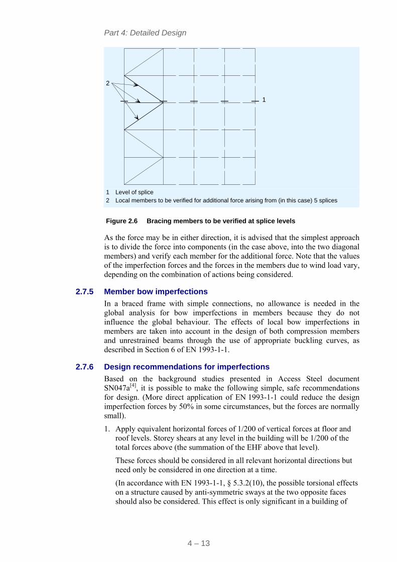
Part 4: Detailed Design
4 – 13
1
2
1 Level of splice 2 Local members to be verified for additional force arising from (in this case) 5 splices
Figure 2.6 Bracing members to be verified at splice levels
As the force may be in either direction, it is advised that the simplest approach is to divide the force into components (in the case above, into the two diagonal members) and verify each member for the additional force. Note that the values of the imperfection forces and the forces in the members due to wind load vary, depending on the combination of actions being considered.
2.7.5 Member bow imperfections
In a braced frame with simple connections, no allowance is needed in the global analysis for bow imperfections in members because they do not influence the global behaviour. The effects of local bow imperfections in members are taken into account in the design of both compression members and unrestrained beams through the use of appropriate buckling curves, as described in Section 6 of EN 1993-1-1.
2.7.6 Design recommendations for imperfections
Based on the background studies presented in Access Steel document SN047a[4], it is possible to make the following simple, safe recommendations for design. (More direct application of EN 1993-1-1 could reduce the design imperfection forces by 50% in some circumstances, but the forces are normally small).
1. Apply equivalent horizontal forces of 1/200 of vertical forces at floor and roof levels. Storey shears at any level in the building will be 1/200 of the total forces above (the summation of the EHF above that level).
These forces should be considered in all relevant horizontal directions but need only be considered in one direction at a time.
(In accordance with EN 1993-1-1, § 5.3.2(10), the possible torsional effects on a structure caused by anti-symmetric sways at the two opposite faces should also be considered. This effect is only significant in a building of
Part 4: Detailed Design
4 – 14
very low torsional stiffness on plan, a situation which is unlikely to occur in practice).
2. Verify that all columns are tied into all attached beams by connections with a minimum resistance of 1,0% of the column axial force, i.e. that the tying resistance of the beam to column connection is at least 0,01× NEd,column.
3. Verify that all the equivalent horizontal forces in each column can be transferred into the relevant bracing system. Diaphragm action in the floor slab may be mobilised to satisfy this condition.
In accordance with EN 1993-1-1, § 5.3.3(1), a reduction factor
m =
m1
15,0
may be applied, where m is the number of columns to be restrained.
2.8 Design summary ‘Simple’ design and construction provides the most economical approach
for low and medium rise frames.
System(s) of triangulated bracing or concrete core(s) provide resistance to horizontal forces and overall frame stability.
‘Simple’ connections have been proven by experience to provide sufficient strength, shear and rotation capacity to satisfy the assumptions of this method.
Beams are designed to span between grid lines.
Columns are designed for axial loading only, with no account of pattern loading and only nominal moments. The value of the nominal moments will be based on the equilibrium model adopted for the connections, as described in Section 3.3.
Concrete cores may generally be assumed to provide sufficient stiffness for all potential second order effects to be ignored.
For low-rise (2 or 3 storey) braced frames, designing the bracing for horizontal actions of 2,5% of vertical actions in accordance with section 2.6 will provide sufficient horizontal stiffness that all potential second order effects may be ignored.
Frames of intermediate stiffness, where 3 < cr < 10, may be analysed by first order analysis, providing all relevant actions are amplified by the factor
cr
11
1
Frames with cr < 3,0 should be avoided.
The effects of sway imperfections and imperfections at splices may simply be addressed by applying equivalent horizontal forces of 1/200 of vertical forces, in accordance with Section 2.7.6 of this publication.
Part 4: Detailed Design
4 – 15
3 PRACTICAL GLOBAL ANALYSIS FOR ‘SIMPLE CONSTRUCTION’
3.1 Introduction This Section provides guidance on the global analysis of a low or medium rise building, taking appropriate account of the specific aspects of frame behaviour addressed in Section 2. The Section addresses both persistent and transient design situations. Design for accidental situations is addressed in Section 6.
3.2 Actions and their combinations Buildings have to be designed for the combinations of actions set out in EN 1990[5], § 6.4.3.2; this aspect is discussed in more detail in Multi-storey steel buildings. Part 3: Actions[6]
For the ultimate limit state, the basic combination of actions is given in expression (6.10) as:
1i
i,ki,0i,Q
1j
1,k1,Qpj,kj,G QQPG 6.10
This combination includes the permanent actions Gk,j, the pre-stressing action P (not normally applicable in multi-storey steel building frames), the leading variable action Qk,1 and the various accompanying variable actions Qk,i. Partial factors, , are applied to the characteristic value of each action and additionally a factor 0 is applied to each accompanying action.
Alternatively, for the STR and GEO Limit States (see EN 1990-1-1 § 6.4.1), EN 1990[5] permits the use of the least favourable of the combinations of actions given in expressions (6.10a) and (6.10b) for the ultimate limit state.
1
,k,0,Q1
1,k1,01,Qp,k,Gi
iiij
jj QQPG 6.10a
1
,k,0,Q1
1,k1,Qp,k,Gi
iiij
jj QQPG 6.10b
The first of these two expressions effectively treats all variable actions as accompanying the permanent action (and thus applies 0 to all variable actions) while the second considers the leading variable action as the primary action and allows a modest reduction in the design value of the permanent action.
Although EN 1990 permits the use of equations (6.10a) and (6.10b) as an alternative to (6.10), the National Annex may give guidance regarding the combination that should be used.
Recommended values of the partial factors and factors on accompanying actions are given in EN 1990 but these are confirmed or varied by the Nationally Determined Parameters (NDP) in the National Annex.
Part 4: Detailed Design
4 – 16
If the recommended values of NDP are adopted, it will be found that the option of using expressions (6.10a)/(6.10b) is generally less onerous than using (6.10).
It will also be found that, apart from storage areas, (6.10b) is the more onerous of (6.10a) and (6.10b), unless the permanent action is much (4,5 times) greater than the variable action. This is most unlikely in a multi-storey framed building.
Three types of combination of actions at the serviceability limit state are considered – characteristic, frequent and quasi-permanent. Expressions for these are given in 6.14b, 6.15b and 6.16b, as follows:
1
,k,01
1,k,kGi
iij
j QQP 6.14b
1
,k,21
1,k1,1,ki
iij
j QQPG 6.15b
1
,k,21
,ki
iij
j QPG 6.16b
It is implicit in these expressions that partial factors are equal to unity. The factors for accompanying actions (0, 1 and 2) are given in EN 1990[5], but the National Annex may give additional information as to what values should be used. These values are specific for the type of load being considered, i.e. 1 for snow is different from 1 for wind.
For braced multi-storey building frames, the serviceability limit states to be considered will normally be those for the vertical and horizontal deflections of the frame and the dynamic performance of the floors. Crack widths may also need to be controlled for durability reasons in some situations (such as in car parks) and occasionally for appearance reasons. Guidance is given in EN 1992-1-1[7] and in Multi-storey steel buildings. Part 3: Actions[6].
3.3 Analysis for gravity loads With the assumption of pinned behaviour for beam/column connections, all floor systems adopted for multi-storey buildings are statically determinate. Simple load allocation may be adopted to determine the governing moments, shears and axial forces in all elements: floors slabs, secondary beams, primary beams, columns and connections.
EN 1991-1-1, § 6.2.1(4) defines the reduction factor, A, that may be applied to gravity loads on floors, beams and roofs according to the area supported by the appropriate member.
§ 6.2.2(2) defines an equivalent factor, n, for gravity loads on walls and columns, depending on the number of storeys loading the appropriate element.
Not all imposed gravity loads qualify for the reduction. For example, it would not be appropriate where:
Loads have been specifically determined from knowledge of the proposed use
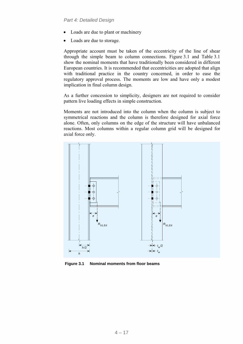
Part 4: Detailed Design
4 – 17
Loads are due to plant or machinery
Loads are due to storage.
Appropriate account must be taken of the eccentricity of the line of shear through the simple beam to column connections. Figure 3.1 and Table 3.1 show the nominal moments that have traditionally been considered in different European countries. It is recommended that eccentricities are adopted that align with traditional practice in the country concerned, in order to ease the regulatory approval process. The moments are low and have only a modest implication in final column design.
As a further concession to simplicity, designers are not required to consider pattern live loading effects in simple construction.
Moments are not introduced into the column when the column is subject to symmetrical reactions and the column is therefore designed for axial force alone. Often, only columns on the edge of the structure will have unbalanced reactions. Most columns within a regular column grid will be designed for axial force only.
h
h /2
R Rb1,Ed b1,Ed
e e
tw/2
tw Figure 3.1 Nominal moments from floor beams
Part 4: Detailed Design
4 – 18
Table 3.1 Nominal Values of eccentricity 'e' typically used for ‘simple construction’ in different European Countries
Country Major axis eccentricity Minor Axis eccentricity
Belgium h/2 0
Netherlands h/2 0
Germany h/2 0
France h/2 0
Spain h/2 0
Italy h/2 0
The nominal moments may be shared equally between the upper and lower columns, provided the ratio of their stiffness (I/L) does not exceed 1,5[4]. Outside this limit, the moments should be distributed in proportion to column stiffness.
1
2M
M uL
lowerlower
upperupper
L
u
LI
LI
M
M
But Mupper = Mlower when 0,67 < lowerlower
upperupper
/
/
LI
LI< 1,5
1 Column 2 Floor beam
Figure 3.2 Distribution of nominal moments from floor beams
3.4 Allowance for second order effects There are two options for low and medium rise frames and the allowance of second order effects.
3.4.1 Ensure cr > 10
For small scale construction of up to three storeys, it may be appropriate to ensure cr is greater than 10 by applying the simplified approaches of Section 2.6 of this document.
Part 4: Detailed Design
4 – 19
3.4.2 Design for 3 < cr < 10
More generally, it is appropriate to design the horizontal bracing structure for strength. It is then necessary to take appropriate account of second order effects in accordance with § 2.4.2(2) of EN 1993-1-1. The steps described in Section 2.5 should be followed.
3.5 Design Summary References are to EN 1990-1-1[5].
Use the least favourable of Equations 6.10a and 6.10b (where allowed by the National Annex) for the combination of actions for the ultimate limit state.
Use Equations 6.14b, 6.15b, 6.16b for combinations of actions for the serviceability limit state, noting any recommendations in the National Annex.
Use § 6.2.1(2) and (4) to determine the permissible reductions in variable actions applied to large areas.
Carry out the analysis in accordance with Section 3.3 of this publication for gravity loads and 3.4 to assess the significance of second order effects and allow for them if necessary.
Part 4: Detailed Design
4 – 20
4 SERVICEABILITY LIMIT STATE
4.1 General EN 1990[5], § 3.4 and 6.5 and EN 1993-1-1[1], § 7 require structures to satisfy the Serviceability Limit State. Criteria relevant to multi-storey buildings are:
Horizontal deflections
Vertical deflections on floor systems
Dynamic response.
The general philosophy of the Eurocodes is not to offer prescribed general limits for horizontal and vertical deflections, but to recommend that limits should be specified for each project and agreed with the client. They acknowledge that National Annexes may specify relevant limits for general applications in specific countries.
Sections 4.3 and 4.4 provide the definition of horizontal and vertical deflections and suggest some limits, based on Access Steel document SN034a[4].
4.2 Load combinations As discussed in Multi-storey steel buildings. Part 3: Actions[6], different combinations of actions are used for serviceability and ultimate limit states. It is noteworthy that some countries only apply limits to response to variable actions (i.e. deflections due to permanent actions are not limited).
4.3 Horizontal deflection limits The definitions of horizontal deflections in Annex A1 to EN 1990[5] are shown in Figure 4.10. Table 4.1 summarises typical horizontal deflection limits used in Europe.
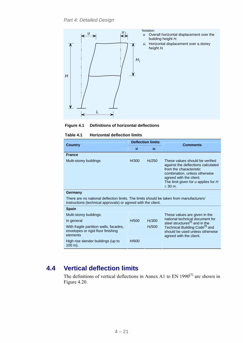
Part 4: Detailed Design
4 – 21
L
H
H
u u i
i
Notation: u Overall horizontal displacement over the
building height H. ui Horizontal displacement over a storey
height Hi
Figure 4.1 Definitions of horizontal deflections
Table 4.1 Horizontal deflection limits
Deflection limits Country
u ui Comments
France
Multi-storey buildings H/300 Hi/250 These values should be verified against the deflections calculated from the characteristic combination, unless otherwise agreed with the client. The limit given for u applies for H 30 m.
Germany
There are no national deflection limits. The limits should be taken from manufacturers’ instructions (technical approvals) or agreed with the client.
Spain
Multi-storey buildings:
In general H/500 Hi/300
With fragile partition walls, facades, envelopes or rigid floor finishing elements
Hi/500
High rise slender buildings (up to 100 m).
H/600
These values are given in the national technical document for steel structures[8] and in the Technical Building Code[9] and should be used unless otherwise agreed with the client.
4.4 Vertical deflection limits The definitions of vertical deflections in Annex A1 to EN 1990[5] are shown in Figure 4.20.
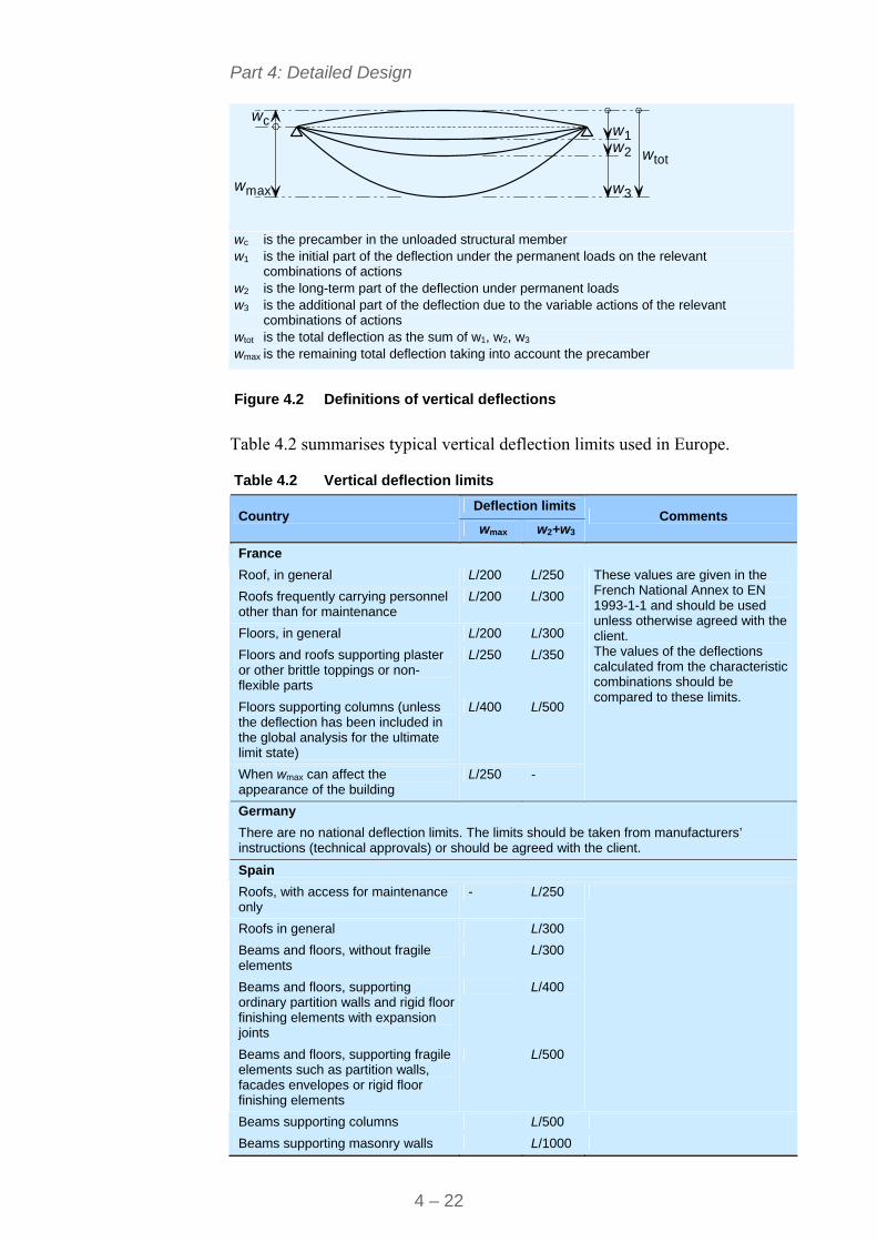
Part 4: Detailed Design
4 – 22
c
max
www
ww
wtot
12
3
wc is the precamber in the unloaded structural member w1 is the initial part of the deflection under the permanent loads on the relevant
combinations of actions w2 is the long-term part of the deflection under permanent loads w3 is the additional part of the deflection due to the variable actions of the relevant
combinations of actions wtot is the total deflection as the sum of w1, w2, w3 wmax is the remaining total deflection taking into account the precamber
Figure 4.2 Definitions of vertical deflections
Table 4.2 summarises typical vertical deflection limits used in Europe.
Table 4.2 Vertical deflection limits
Deflection limits Country
wmax w2+w3 Comments
France
Roof, in general L/200 L/250
Roofs frequently carrying personnel other than for maintenance
L/200 L/300
Floors, in general L/200 L/300
Floors and roofs supporting plaster or other brittle toppings or non-flexible parts
L/250 L/350
Floors supporting columns (unless the deflection has been included in the global analysis for the ultimate limit state)
L/400 L/500
When wmax can affect the appearance of the building
L/250 -
These values are given in the French National Annex to EN 1993-1-1 and should be used unless otherwise agreed with the client. The values of the deflections calculated from the characteristic combinations should be compared to these limits.
Germany
There are no national deflection limits. The limits should be taken from manufacturers’ instructions (technical approvals) or should be agreed with the client.
Spain
Roofs, with access for maintenance only
- L/250
Roofs in general L/300
Beams and floors, without fragile elements
L/300
Beams and floors, supporting ordinary partition walls and rigid floor finishing elements with expansion joints
L/400
Beams and floors, supporting fragile elements such as partition walls, facades envelopes or rigid floor finishing elements
L/500
Beams supporting columns L/500
Beams supporting masonry walls L/1000
Part 4: Detailed Design
4 – 23
4.5 Precambering Deflections under permanent loads may be a significant part of the overall deflection of floor beams. This is particularly true for composite floor systems that are constructed without propping (as is recommended for fast, simple construction).
In such cases, designers should specify pre-cambering to ensure that the primary and secondary floor systems are flat and level once the structure has been completed. Annex A1 of EN 1990[5] makes specific provision for recognising the benefits of precambering.
4.6 Dynamic response Annex A.1.4.4 of EN 1990 states the following requirements for the dynamic response of all structures.
Vibrations (1) To achieve satisfactory vibration behaviour of buildings and their structural members under serviceability conditions, the following aspects, amongst others, should be considered:
a) the comfort of the user;
b) the functioning of the structure or its structural members (e.g. cracks in partitions, damage to cladding, sensitivity of building contents to vibrations).
Other aspects should be considered for each project and agreed with the client.
(2) For the serviceability limit state of a structure or a structural member not to be exceeded when subjected to vibrations, the natural frequency of vibrations of the structure or structural member should be kept above appropriate values which depend upon the function of the building and the source of the vibration, and agreed with the client and/or the relevant authority.
(3) If the natural frequency of vibrations of the structure is lower than the appropriate value, a more refined analysis of the dynamic response of the structure, including the consideration of damping, should be performed.
Note: for further guidance, see EN 1990-1-1, EN 1990-1-4 and ISO 10137
(4) Possible sources of vibration that should be considered include walking, synchronised movements of people, machinery, ground borne vibrations from traffic, and wind actions. These, and other source, should be specified for each project and agreed with the client.
In practice, for low and medium rise buildings for commercial or residential use, the key issue is the dynamic response of the floor system to human excitation, primarily either from walking or from a single heavy ‘foot-fall’.
Part 4: Detailed Design
4 – 24
The dynamic response of floor systems to human excitation is complex, for three reasons:
The nature of the excitation is uncertain in magnitude, duration and frequency of occurrence.
The structural response is substantially influenced by the magnitude of the damping in the structure and the damping effect of non-structural components of the building and its fittings, furnishings and furniture.
Human perception of vibration and the definition of appropriate acceptance criteria are both very imprecise, varying between individuals and for a single individual over time.
It must be emphasised that a floor that has a ‘lively’ response to human excitation is most unlikely to have inadequate or impaired strength. Traditional timber floors have always exhibited such behaviour yet have performed satisfactorily. However, both the increasing use of longer span steel floor systems and the move to lighter construction increase the probability that performance may cause discomfort to some users. Designers therefore need to pay attention to this aspect of serviceability.
Historically, designers have used the natural frequency of the floor as the sole measure of acceptable performance. A sufficiently high natural frequency means that a floor is effectively ‘tuned’ out of the frequency range of the first harmonic component of walking. However, resonance might still occur with higher harmonics. As a guideline, a fundamental frequency above 4 Hz is usually appropriate, but no requirements are given in EN 1994[2] and the designer should seek guidance in the national regulations.
Much more effective, though more complex, methods of assessing dynamic serviceability have emerged recently:
Vibration design of floors RF32-CT-2007-00033: This is freely available from RWTH Aachen. It provides a single mode analysis on the floor.
Design of floors for vibration: A new Approach[10] presents a more comprehensive, multi-mode approach to the same methods of assessment.
Design software is becoming available that takes full account of the method presented in Reference 10.
4.7 Design summary Verify the horizontal deflections defined in Section 4.3 against the criteria
defined in the relevant National Annex
Verify the relevant vertical deflection, defined in Section 4.4 against the criteria defined in the relevant National Annex
Consider pre-cambering for beams greater than 10 m in length
Verify the dynamic response of the floor against one of the references given in Section 4.6.
Part 4: Detailed Design
4 – 25
5 ULTIMATE LIMIT STATE
5.1 Introduction Design for the Ultimate Limit State, i.e. verification of the strength of all the structural components of the building to resist the actions identified by the global analysis, remains the core of the detailed design process.
Fortunately, many design aids are now available to assist designers; these have relieved them of much of the detailed effort that was previously required. The following sections provide comprehensive guidance on how to take full account of these aids, while still providing reference back to their basis in the Eurocodes.
5.2 Floor systems 5.2.1 Floor slab
Either a composite slab or a precast floor will have been chosen during conceptual design. Both may be designed from first principles but this is rarely, if ever, done in practice.
A composite slab may be designed to EN 1993-1-3[1] for the construction condition, EN 1994-1-1[2] for the completed structure and EN 1994-1-2 for the fire condition.
A precast reinforced concrete floor may be designed to EN 1992-1-1[7].
All these standards make provision for design assisted by testing, in accordance with Annex D of EN 1990[5].
For such specialist construction products with wide application in practice, the design assisted by testing route has been adopted by the manufacturers because it offers greater design resistance than that determined by calculation. Manufacturers supplying into a national market will usually offer appropriate design tables which take full account of Nationally Determined Parameters defined in relevant National Annexes.
Designers should use these design tables wherever they are available.
5.2.2 Downstand non-composite beams
Downstand non-composite floor beams are used to support precast floor systems, and, possibly, composite floor slabs that are not attached to their supporting beams by shear connectors. Downstand roof beams generally carry the purlins that support roof systems
Depending on the details of construction, these beams may be:
Fully restrained for both construction and in-service conditions.
Restrained at points of load application for both construction and in-service conditions.
Part 4: Detailed Design
4 – 26
Unrestrained for the construction condition and either:
- Fully restrained for the in-service condition (floor beams supporting precast planks)
- Restrained at points of load application for the in-service condition
- Unrestrained for both construction and in-service conditions.
Depending on the slenderness of the beams, there may be a substantial difference of resistance between restrained and unrestrained conditions. It follows that, where the restraint condition improves when the structure is fully constructed, separate verifications should be carried out for both construction and in-service stages.
The detailed design process is presented in Figure 5.1 to Figure 5.4. It is possible to cover all the cases listed above by appropriate consideration of the restraint conditions and hence the design buckling resistance described in Figure 5.4.
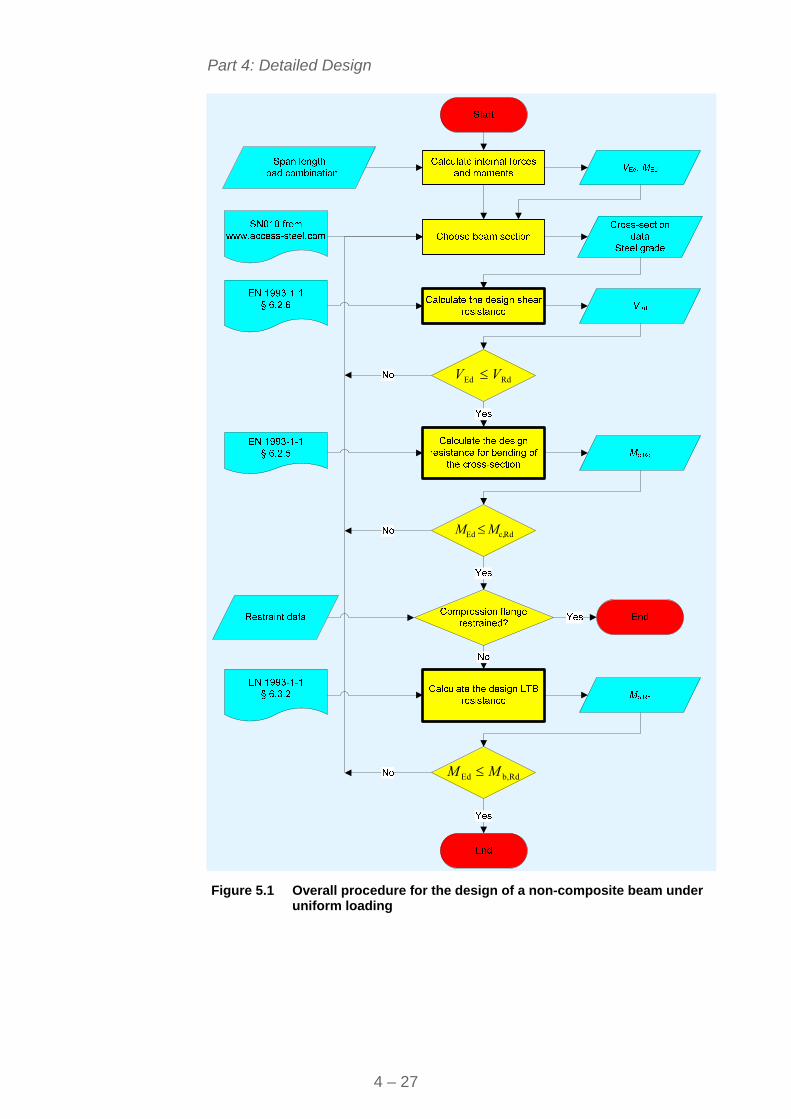
Part 4: Detailed Design
4 – 27
Rdc,Ed MM
Rdb,Ed MM
RdEd VV
Figure 5.1 Overall procedure for the design of a non-composite beam under
uniform loading
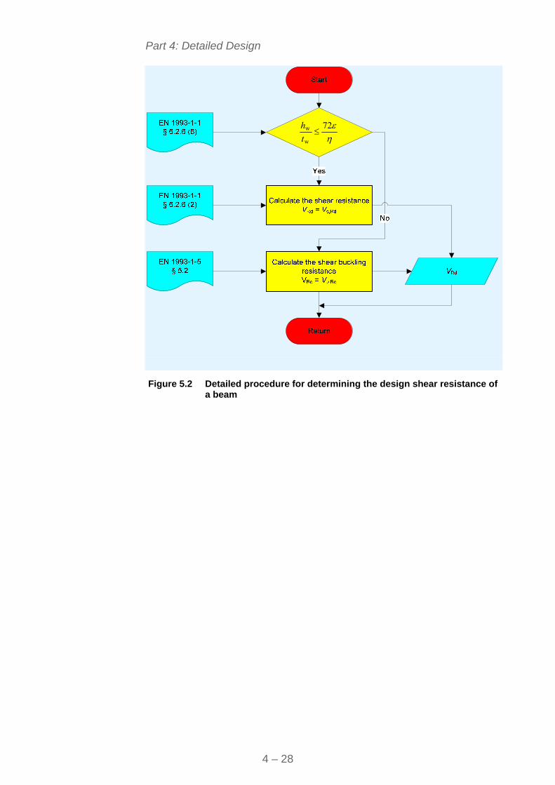
Part 4: Detailed Design
4 – 28
72
w
w t
h
Figure 5.2 Detailed procedure for determining the design shear resistance of
a beam
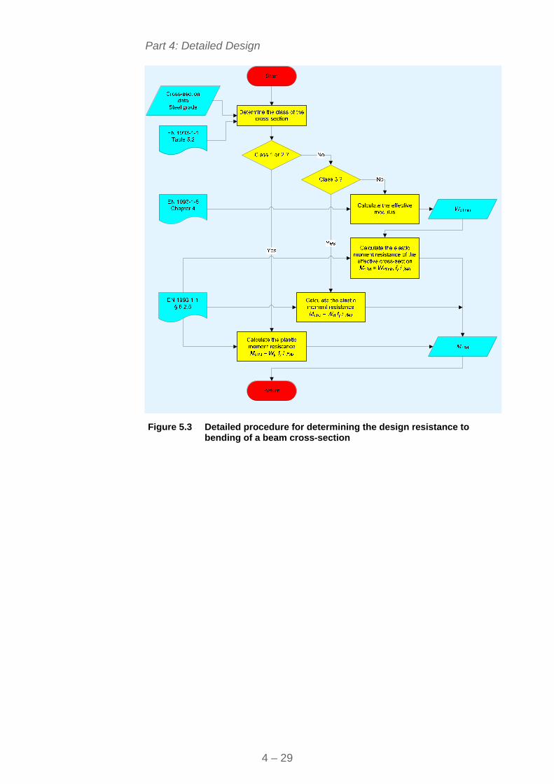
Part 4: Detailed Design
4 – 29
Figure 5.3 Detailed procedure for determining the design resistance to
bending of a beam cross-section
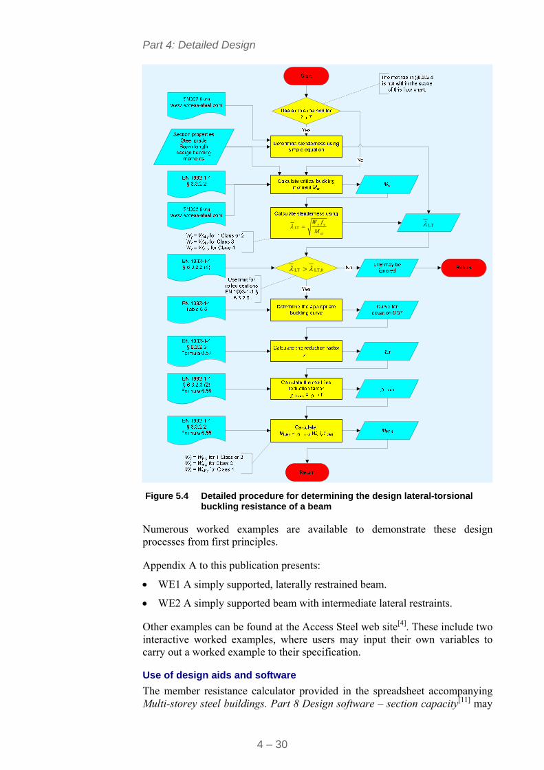
Part 4: Detailed Design
4 – 30
cr
yyLT
M
fW
LT,0LT
LT
Figure 5.4 Detailed procedure for determining the design lateral-torsional
buckling resistance of a beam
Numerous worked examples are available to demonstrate these design processes from first principles.
Appendix A to this publication presents:
WE1 A simply supported, laterally restrained beam.
WE2 A simply supported beam with intermediate lateral restraints.
Other examples can be found at the Access Steel web site[4]. These include two interactive worked examples, where users may input their own variables to carry out a worked example to their specification.
Use of design aids and software
The member resistance calculator provided in the spreadsheet accompanying Multi-storey steel buildings. Part 8 Design software – section capacity[11] may
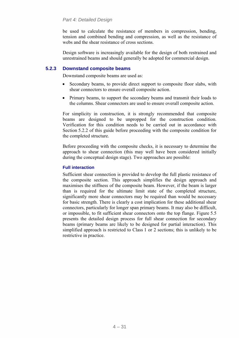
Part 4: Detailed Design
4 – 31
be used to calculate the resistance of members in compression, bending, tension and combined bending and compression, as well as the resistance of webs and the shear resistance of cross sections.
Design software is increasingly available for the design of both restrained and unrestrained beams and should generally be adopted for commercial design.
5.2.3 Downstand composite beams
Downstand composite beams are used as:
Secondary beams, to provide direct support to composite floor slabs, with shear connectors to ensure overall composite action.
Primary beams, to support the secondary beams and transmit their loads to the columns. Shear connectors are used to ensure overall composite action.
For simplicity in construction, it is strongly recommended that composite beams are designed to be unpropped for the construction condition. Verification for this condition needs to be carried out in accordance with Section 5.2.2 of this guide before proceeding with the composite condition for the completed structure.
Before proceeding with the composite checks, it is necessary to determine the approach to shear connection (this may well have been considered initially during the conceptual design stage). Two approaches are possible:
Full interaction
Sufficient shear connection is provided to develop the full plastic resistance of the composite section. This approach simplifies the design approach and maximises the stiffness of the composite beam. However, if the beam is larger than is required for the ultimate limit state of the completed structure, significantly more shear connectors may be required than would be necessary for basic strength. There is clearly a cost implication for these additional shear connectors, particularly for longer span primary beams. It may also be difficult, or impossible, to fit sufficient shear connectors onto the top flange. Figure 5.5 presents the detailed design process for full shear connection for secondary beams (primary beams are likely to be designed for partial interaction). This simplified approach is restricted to Class 1 or 2 sections; this is unlikely to be restrictive in practice.
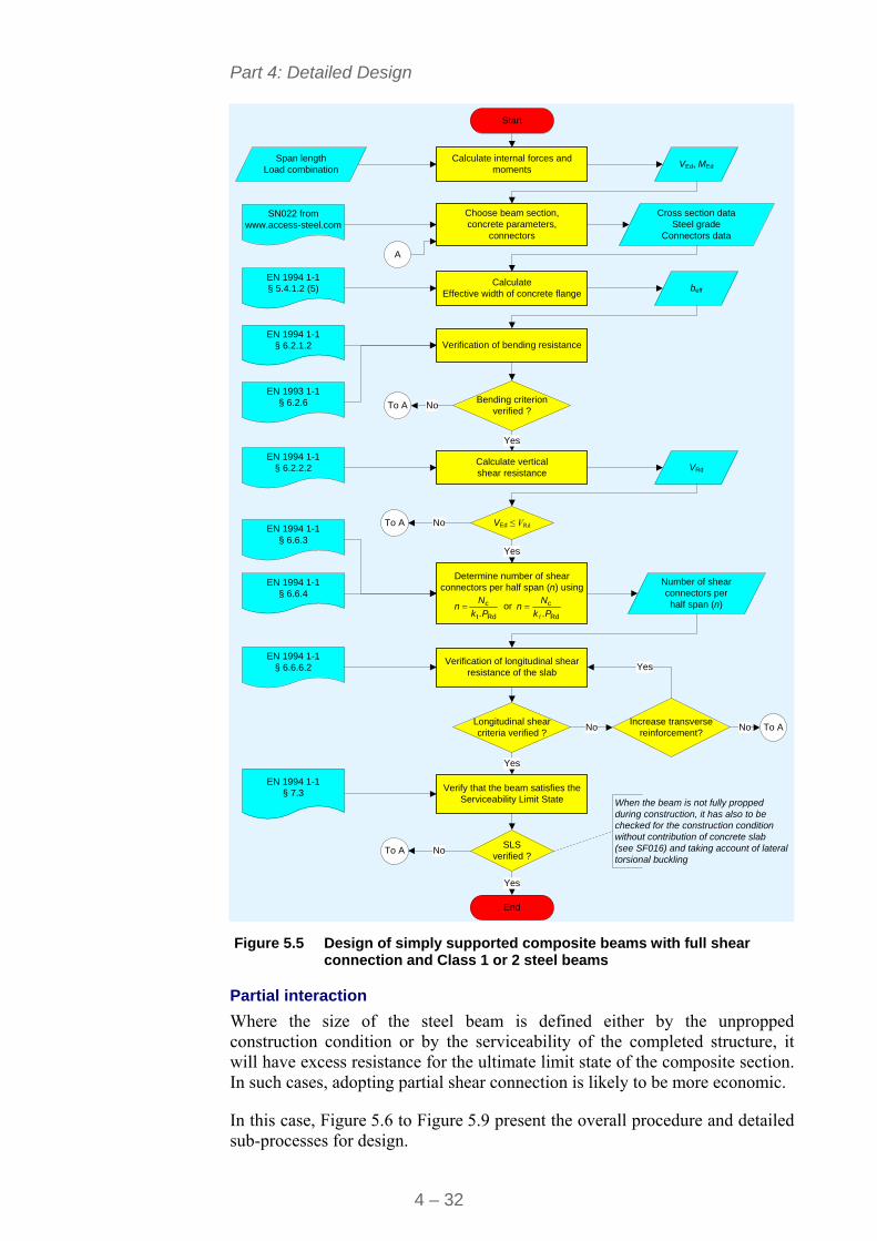
Part 4: Detailed Design
4 – 32
End
Bending criterion verified ?
Calculate internal forces and moments
Span lengthLoad combination
Start
VEd, MEd
Choose beam section,concrete parameters,
connectors
Calculate Effective width of concrete flange
EN 1994 1-1§ 5.4.1.2 (5)
EN 1994 1-1 § 6.6.3
Number of shear connectors per half span (n)
Cross section dataSteel grade
Connectors data
beff
VRd
Yes
VEd ≤ VRd
No
No
Longitudinal shear criteria verified ?
Yes
Yes
No
When the beam is not fully propped during construction, it has also to be checked for the construction condition without contribution of concrete slab (see SF016) and taking account of lateral torsional buckling
EN 1994 1-1§ 6.6.6.2
Verification of bending resistance
Calculate verticalshear resistance
Verification of longitudinal shear resistance of the slab
SN022 from www.access-steel.com
EN 1994 1-1 § 6.2.1.2
EN 1994 1-1§ 6.2.2.2
Determine number of shear connectors per half span (n) using
Rdt
c
.Pk
Nn or
Rd
c
.Pk
Nn
SLSverified ?
Verify that the beam satisfies the Serviceability Limit State
Yes
No
EN 1994 1-1§ 7.3
EN 1993 1-1 § 6.2.6
Increase transverse reinforcement?
Yes
No
To A
To A
To A
A
To A
EN 1994 1-1 § 6.6.4
Figure 5.5 Design of simply supported composite beams with full shear
connection and Class 1 or 2 steel beams
Partial interaction
Where the size of the steel beam is defined either by the unpropped construction condition or by the serviceability of the completed structure, it will have excess resistance for the ultimate limit state of the composite section. In such cases, adopting partial shear connection is likely to be more economic.
In this case, Figure 5.6 to Figure 5.9 present the overall procedure and detailed sub-processes for design.
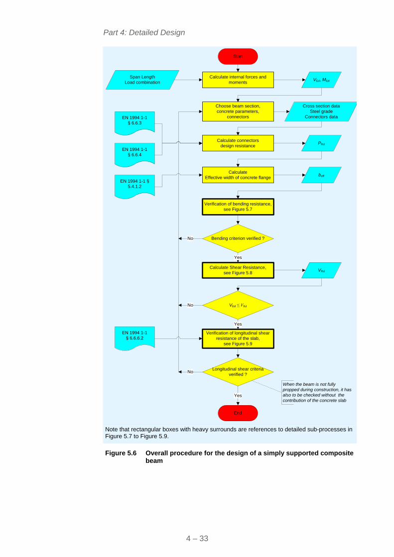
Part 4: Detailed Design
4 – 33
End
Bending criterion verified ?
Calculate internal forces and moments
Verification of bending resistance, see Figure 5.7
Span LengthLoad combination
Start
VEd, MEd
Choose beam section,concrete parameters,
connectors
Calculate Effective width of concrete flange
EN 1994 1-1 § 5.4.1.2
Calculate connectors design resistance
EN 1994 1-1 § 6.6.4
PRd
Cross section dataSteel grade
Connectors data
beff
VRd
Yes
VEd ≤ VRd
No
No
Verification of longitudinal shear resistance of the slab,
see Figure 5.9
Longitudinal shear criteria verified ?
Yes
Yes
No
Calculate Shear Resistance,see Figure 5.8
When the beam is not fully propped during construction, it has also to be checked without the contribution of the concrete slab
EN 1994 1-1§ 6.6.6.2
EN 1994 1-1 § 6.6.3
Note that rectangular boxes with heavy surrounds are references to detailed sub-processes in Figure 5.7 to Figure 5.9.
Figure 5.6 Overall procedure for the design of a simply supported composite
beam
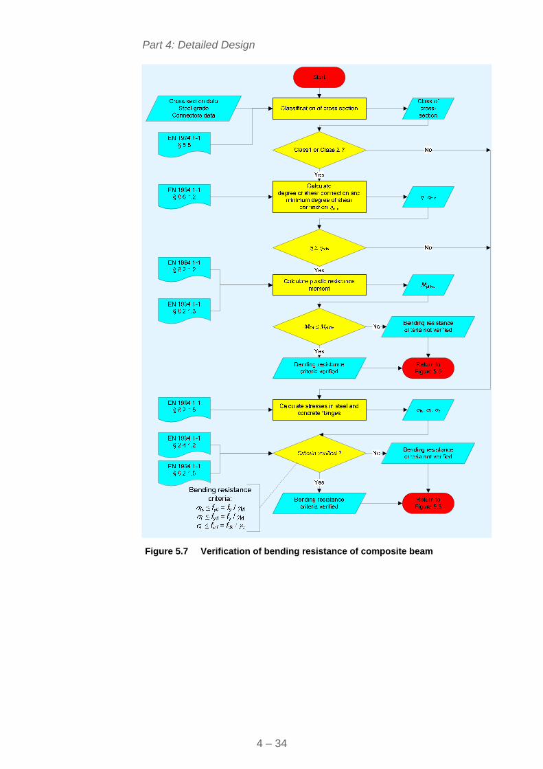
Part 4: Detailed Design
4 – 34
Figure 5.7 Verification of bending resistance of composite beam
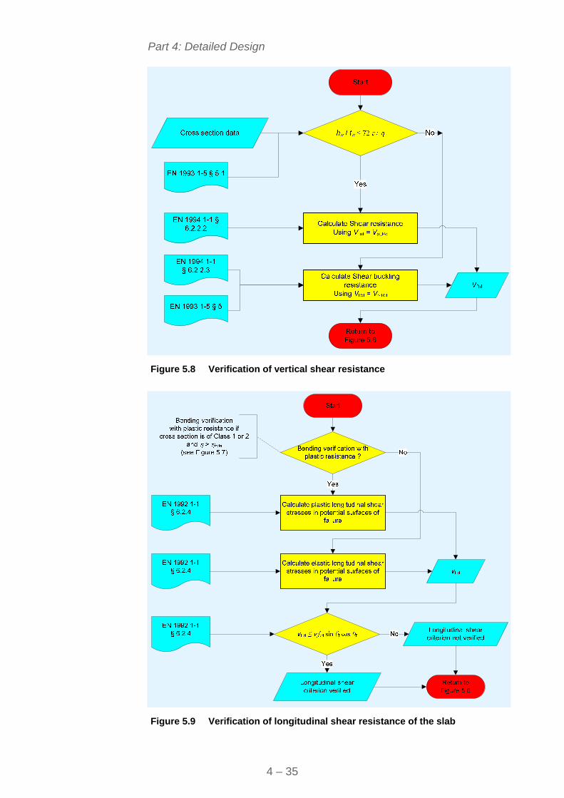
Part 4: Detailed Design
4 – 35
Figure 5.8 Verification of vertical shear resistance
Figure 5.9 Verification of longitudinal shear resistance of the slab
Part 4: Detailed Design
4 – 36
Worked examples are provided in Appendix A to demonstrate the detailed design of a secondary and primary composite beam.
Shear connection resistance
In the foregoing verifications of the resistance of composite beams, it should be noted that shear connection resistance is a function of:
The proportions of the deck through which the stud is welded.
The position of the stud(s) with the troughs of the deck
The number of studs within a single trough.
Deck manufacturers’ literature should be consulted to determine appropriate design values.
Appendix A to this publication presents:
WE3 Simply supported secondary composite beam (with partial shear connection)
WE4 Simply supported primary composite beam
Use of design aids and design software
With the number of variables to be considered in composite beams, it is not practical to provide any form of tabular design aid. However, a software specification for a composite beam program has been prepared as a separate part of this publication.
Composite beam software is already available in some major European Markets.
In addition, there are two interactive worked examples on the Access Steel web site[4] that address simply supported secondary and primary beams. Users may input their own variables to carry out a worked example to their specification.
5.2.4 Integrated floor beams
Integrated floor beams, which are principally encased within the depth of the floor slabs, are manufactured by several suppliers. They are all supported by manufacturers’ design data and some are supported by specialist software.
Manufacturers’ design data or software should be used in practice.
5.2.5 Cellular beams
Cellular beams are a specialist form of downstand beam where large openings in the beam webs enable services to share the same depth as the structure within the floor zone.
There are several manufacturers of such products, who have all developed specialist design approaches for ‘cold’ design and some have extended their approaches to encompass the fire limit state. All such software complies with the Eurocodes.
Part 4: Detailed Design
4 – 37
Such beams are therefore always designed to a performance specification for a specific project, using specialist software. Design from first principles to the Eurocodes is not practicable.
5.3 Columns As discussed in Section 3, one of the advantages of simple construction is that internal columns in regular grids may generally be designed for axial load only.
External columns will be subject to both axial loads and moments from connection eccentricity.
A simple design method for columns in simple construction with nominal moments from connection eccentricity is described in Section 5.3.2.
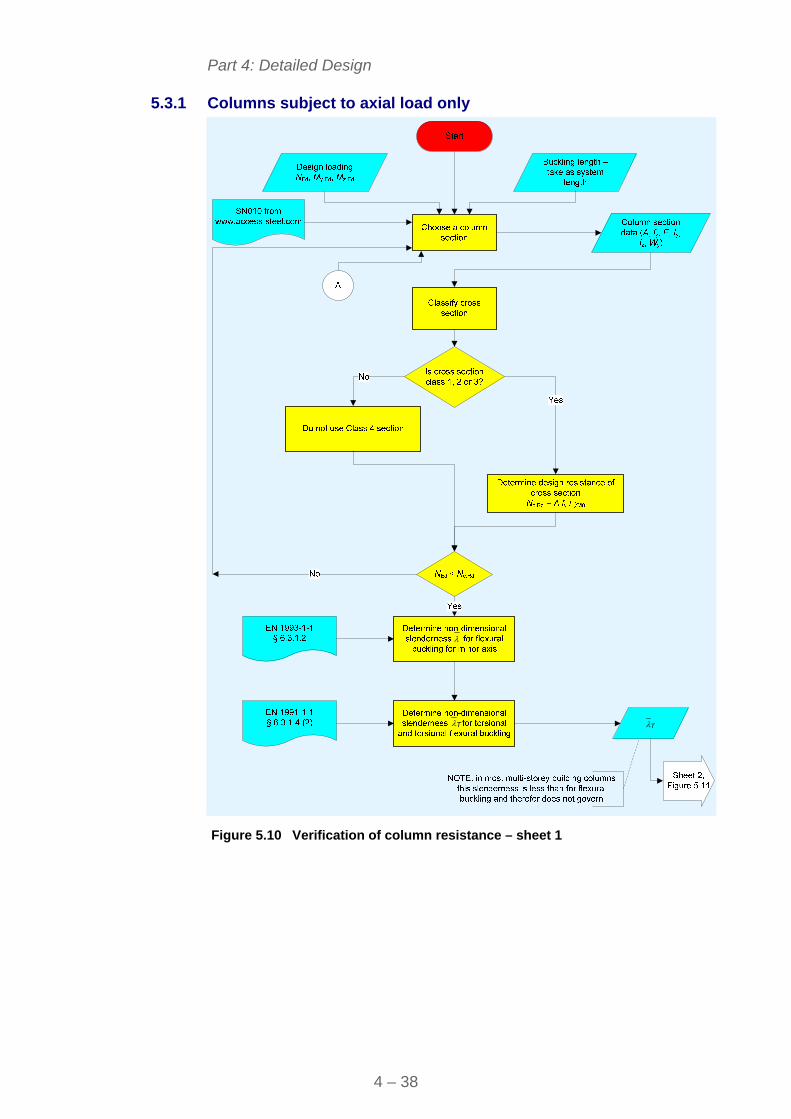
Part 4: Detailed Design
4 – 38
5.3.1 Columns subject to axial load only
T
T
Figure 5.10 Verification of column resistance – sheet 1
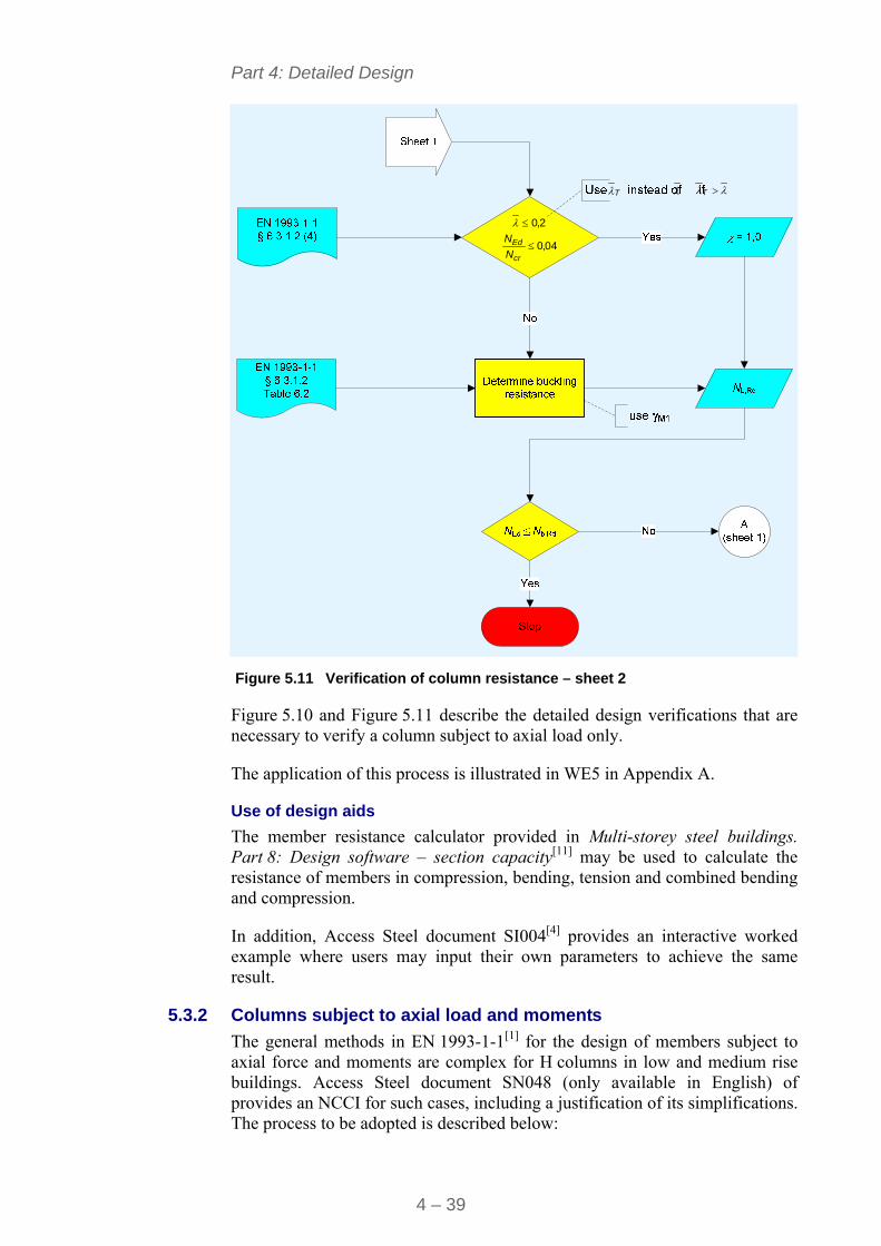
Part 4: Detailed Design
4 – 39
2,0
04,0cr
Ed
N
N
T T
Figure 5.11 Verification of column resistance – sheet 2
Figure 5.10 and Figure 5.11 describe the detailed design verifications that are necessary to verify a column subject to axial load only.
The application of this process is illustrated in WE5 in Appendix A.
Use of design aids
The member resistance calculator provided in Multi-storey steel buildings. Part 8: Design software – section capacity[11] may be used to calculate the resistance of members in compression, bending, tension and combined bending and compression.
In addition, Access Steel document SI004[4] provides an interactive worked example where users may input their own parameters to achieve the same result.
5.3.2 Columns subject to axial load and moments
The general methods in EN 1993-1-1[1] for the design of members subject to axial force and moments are complex for H columns in low and medium rise buildings. Access Steel document SN048 (only available in English) of provides an NCCI for such cases, including a justification of its simplifications. The process to be adopted is described below:
Part 4: Detailed Design
4 – 40
Scope
It may only be adopted where:
The column is a hot rolled I or H section.
The cross-section is Class 1, 2 or 3 under compression.
The bending moment diagrams about each axis are linear.
The column is restrained laterally in both the y and z directions at each floor level but is unrestrained between the floors.
The buckling length is the same in both directions.
Design criterion: Overall buckling
The column must satisfy the single interactive equation:
0,15,1Rdz,cb,
Edz,
Rdb,
Edy,
Rdmin,b,
Ed M
M
M
M
N
N 5.1
where:
Nb,min,Rd is the lesser of Nb,y,Rd and Nb,z,Rd
Nb,y,Rd and Nb,z,Rd are the flexural buckling resistances about the y and the z axes
Mb,Rd is the lateral-torsional buckling resistance
Mcb,z,Rd = min
pl.zy
Wf
for Class 1 and 2 sections
and = min
zel,y
Wf
for Class 3 sections
min = M1
It should be noted that this equation leads to a conservative answer when Annex B of EN 1993-1-1 is used but no study has been done regarding its use with Annex A of the same standard.
If this equation is not satisfied, then the more accurate expressions given in equations 6.61 and 6.62 of EN 1993-1-1 can still be used.
Design criterion: Local verification
For the lowest storey column, if the base is nominally pinned (as is usually the case), the axial force ratio must also satisfy:
Rdy,b,
Ed
N
N< 0,83 5.2
where:
Nb,y,Rd is resistance to buckling about the major axis
Figure 5.12 presents a flowchart to describe this simple procedure.
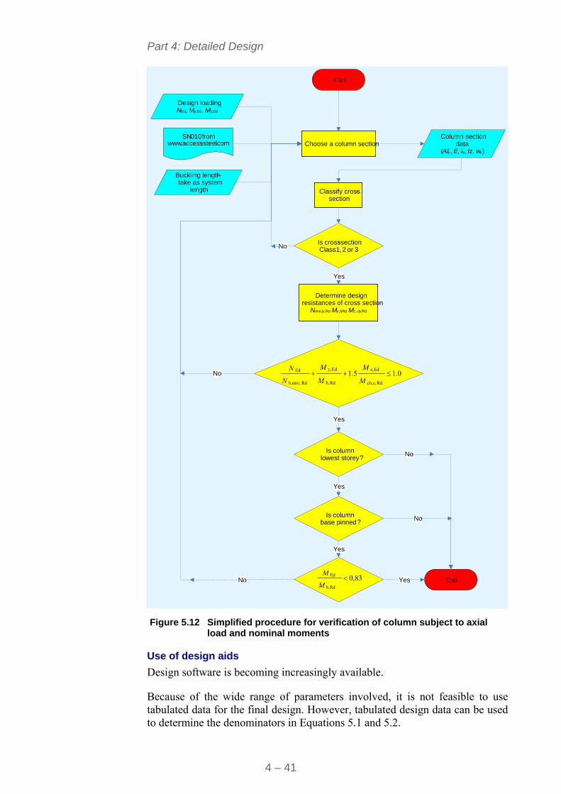
Part 4: Detailed Design
4 – 41
Figure 5.12 Simplified procedure for verification of column subject to axial
load and nominal moments
Use of design aids
Design software is becoming increasingly available.
Because of the wide range of parameters involved, it is not feasible to use tabulated data for the final design. However, tabulated design data can be used to determine the denominators in Equations 5.1 and 5.2.
No
Choose a column section
Design loading N Ed, M y , Ed, M z , Ed
Start
Yes
Buckling length –take as system
length
Yes
End
Column section data
(Af y , E , I y, Iz, wy)
SN 010 from www .access-steel.com
Classify cross-section
Is cross-sectionClass 1, 2 or 3
Determine design resistances of cross section
Nmin,b,Rd My,bRd Mz,cb,Rd
Is column lowest storey?
Is column base pinned?
Yes
Yes
Yes
No
No 0 . 15.1Rdcb,z,
Edz,
Rdb,
Edy,
Rd b,min,
Ed M
M
M
M
N
N
No
No
83,0Rdb,
Ed M
M
Part 4: Detailed Design
4 – 42
5.4 Vertical bracing In a braced steel multi-storey building, the planes of vertical bracing are usually provided by diagonal bracing between two lines of columns, as shown in Figure 5.13.
Figure 5.13 Typical positioning of vertical bracing
The vertical bracing must be designed to resist the forces due to the following:
Wind loads.
Equivalent horizontal forces, representing the effects of initial imperfections, Section 2.4.
These loads are amplified if necessary (cr < 10) to allow for second order effects as described in Section 2.4.
Forces in the individual members of the bracing system must be determined for the appropriate combinations of actions (see Section 3.2). For bracing members, design forces at ULS due to the combination where wind load is the leading action are likely to be the most onerous.
1
4
3
5
2
H H
H
F
H
H
H
H
H
H
b b
b bb
Ed
(a) (b)
(c) (d)
At each floor level, Hi = 0,025 VEd,i where VEd,i is the total design load applied at that floor level
(a) Cross bracing (b) Diagonal bracing (c) Horizontal k bracing (d) Vertical k bracing
Figure 5.14 Typical arrangements of vertical bracing (as Figure 2.3)
Part 4: Detailed Design
4 – 43
The design of the members in any bracing system is generally straightforward. However, the following specific points need to be addressed:
5.4.1 Tension only systems
Figure 5.14(a) shows nominally statically indeterminate systems with cross bracing. In practice, the diagonal members are likely to have a high slenderness (either as flats or as small angles to minimise intrusion into the building). The contribution from the compressive diagonal is therefore ignored.
5.4.2 Load reversal in statically determinate bracing systems
Figure 5.14 (b), (c) and (d) show examples of statically determinate bracing systems. The loading on most bracing systems is fully reversing. It is therefore only necessary to design the diagonals for the more critical condition, when the member is in compression.
5.4.3 Typical bracing members
Bracing members are connected using nominally pinned joints and therefore they carry axial loads only.
Bracing members can be welded or bolted to the main structural members. For bolted connections, use of normal (non-preloaded) bolts is generally appropriate for bracing in the scope of this guide (up to 12 storeys).
Typical sections used as bracing include flats, angles and channels.
Flat bar
Two calculations must be carried out to determine the tension resistance of flat bars:
Gross section resistance, by using equation 6.6 of EN 1993-1-1. The partial factor to be used in this equation is M0.
Net section resistance, by using equation 6.7 of EN 1993-1-1. The partial factor to be used in this equation is M2.
The compression resistance of flats should be carried out by following the method given in EN 1993-1-1, § 6.3.1.
Angles
When the bolts are positioned on the centroid of the section, the tension resistance of angles may be carried out as described for flat bars. When the bolts are positioned away from the centroid of the section the following procedures may be adopted.
Single line of bolts along the member
Where there is a single line of bolts along the angle and the bolts are not aligned with the centroid of the section, there is an additional bending moment due to the eccentricity. EN-1993-1-8, § 3.10.3 gives rules for the calculation of the tensile resistance in this case.
Part 4: Detailed Design
4 – 44
Multiple bolts across the member
Where there is more than one bolt across the section, EN 1993 does not give guidance to account for the eccentricity. In order to account for the additional bending moment the designer has two options:
To use the interaction equations 6.61 and 6.62 of EN 1993-1-1
To use other recognised sources of information, such as Steel building design: Design data[12], which provides an alternative method to account for this effect.
The compression resistance of angles should be calculated by using the method given in § 6.3.1 of EN 1993-1-1.
Where bolts are located away from the centroid of the section, the eccentricity will generate an additional bending moment on the member. As previously described for the tensile resistance of angles, this bending moment can be accounted for in two ways:
By using the interaction equations 6.61 and 6.62 of EN 1993-1-1
By calculating a modified slenderness as given in EN 1993-1-1, Annex BB 1.2 and applying it to the method given in § 6.3.1.
If the angle is welded instead of bolted, the forces distribute across the member and no bending effects needs to be considered.
When the bracing consists of unequal angles, it is important to specify which leg is connected.
Channels
The tension and compression resistances of channels are carried out in a similar way to that described for angles.
Channels are invariably connected through the web, either by welding or by means of bolts. This introduces an eccentricity with respect to the centroid of the section. Although EN 1993-1-1 does not explicitly allow the use of Annex BB 1.2 for the compression resistance of channels, the authors suggest that the approach may also be used for this purpose.
When channels with thin webs are used, bearing of the bolts on the channel may be critical. In order to avoid this problem the designer may specify larger bolts or the web of the channel may be thickened by welding a plate on the web.
5.5 Horizontal bracing Horizontal bracing, or at least floor diaphragm action, is necessary to transmit horizontal forces and requirements for horizontal restraint to planes of vertical bracing.
Where triangulated steel bracing is adopted, the design approaches are essentially the same as those for vertical bracing. However, in general, it is more economical to use the floor as a diaphragm.
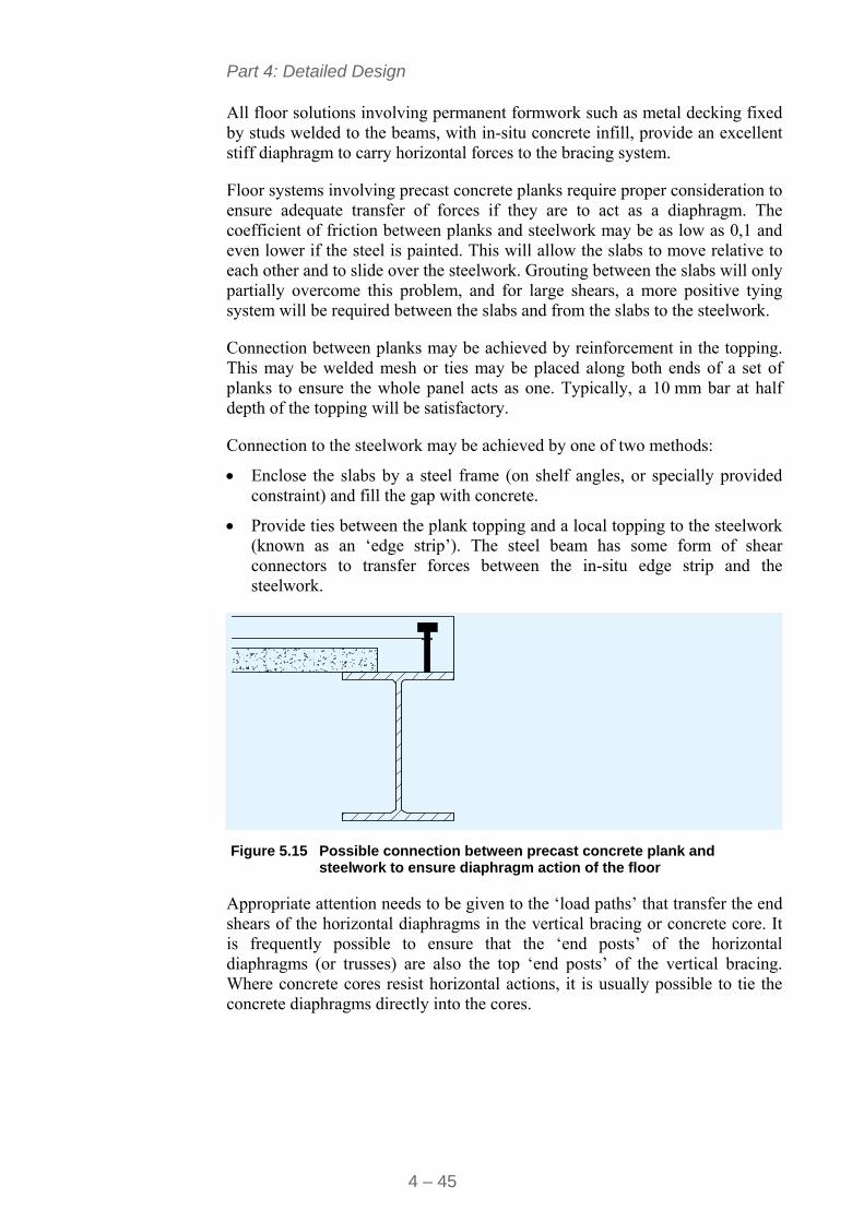
Part 4: Detailed Design
4 – 45
All floor solutions involving permanent formwork such as metal decking fixed by studs welded to the beams, with in-situ concrete infill, provide an excellent stiff diaphragm to carry horizontal forces to the bracing system.
Floor systems involving precast concrete planks require proper consideration to ensure adequate transfer of forces if they are to act as a diaphragm. The coefficient of friction between planks and steelwork may be as low as 0,1 and even lower if the steel is painted. This will allow the slabs to move relative to each other and to slide over the steelwork. Grouting between the slabs will only partially overcome this problem, and for large shears, a more positive tying system will be required between the slabs and from the slabs to the steelwork.
Connection between planks may be achieved by reinforcement in the topping. This may be welded mesh or ties may be placed along both ends of a set of planks to ensure the whole panel acts as one. Typically, a 10 mm bar at half depth of the topping will be satisfactory.
Connection to the steelwork may be achieved by one of two methods:
Enclose the slabs by a steel frame (on shelf angles, or specially provided constraint) and fill the gap with concrete.
Provide ties between the plank topping and a local topping to the steelwork (known as an ‘edge strip’). The steel beam has some form of shear connectors to transfer forces between the in-situ edge strip and the steelwork.
Figure 5.15 Possible connection between precast concrete plank and
steelwork to ensure diaphragm action of the floor
Appropriate attention needs to be given to the ‘load paths’ that transfer the end shears of the horizontal diaphragms in the vertical bracing or concrete core. It is frequently possible to ensure that the ‘end posts’ of the horizontal diaphragms (or trusses) are also the top ‘end posts’ of the vertical bracing. Where concrete cores resist horizontal actions, it is usually possible to tie the concrete diaphragms directly into the cores.
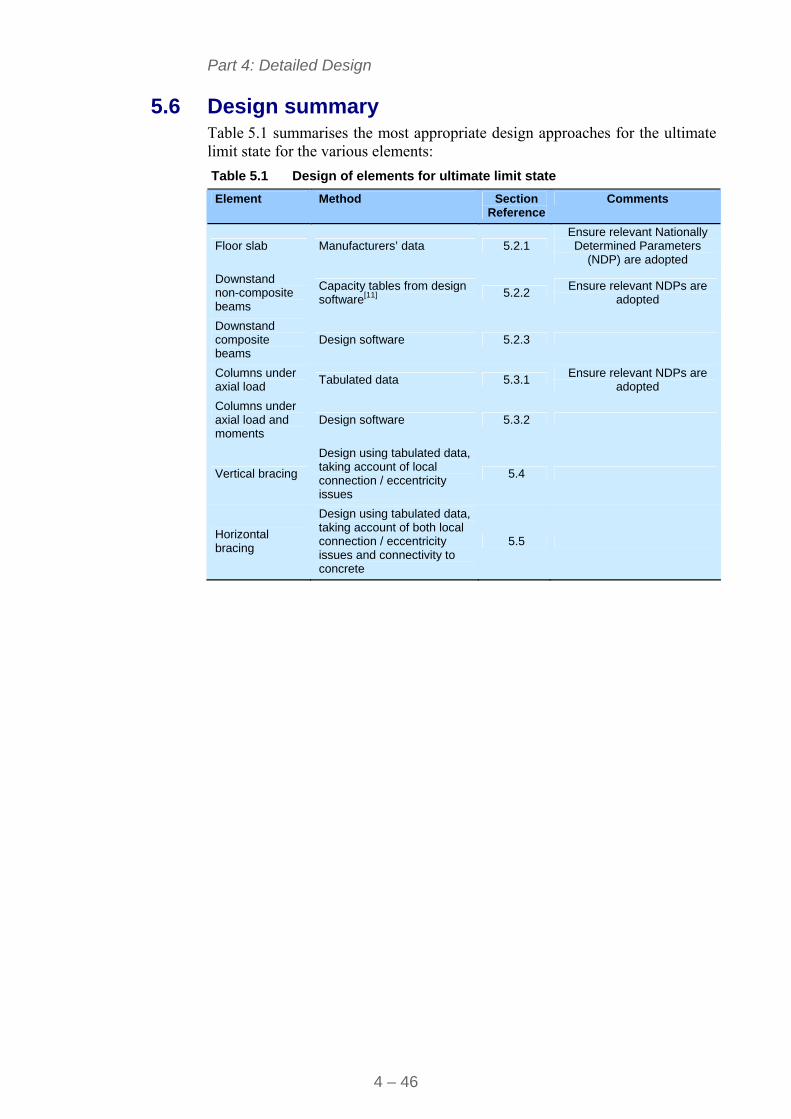
Part 4: Detailed Design
4 – 46
5.6 Design summary Table 5.1 summarises the most appropriate design approaches for the ultimate limit state for the various elements:
Table 5.1 Design of elements for ultimate limit state
Element Method Section Reference
Comments
Floor slab Manufacturers’ data 5.2.1 Ensure relevant Nationally Determined Parameters
(NDP) are adopted
Downstand non-composite beams
Capacity tables from design software[11]
5.2.2 Ensure relevant NDPs are
adopted
Downstand composite beams
Design software 5.2.3
Columns under axial load
Tabulated data 5.3.1 Ensure relevant NDPs are
adopted
Columns under axial load and moments
Design software 5.3.2
Vertical bracing
Design using tabulated data, taking account of local connection / eccentricity issues
5.4
Horizontal bracing
Design using tabulated data, taking account of both local connection / eccentricity issues and connectivity to concrete
5.5
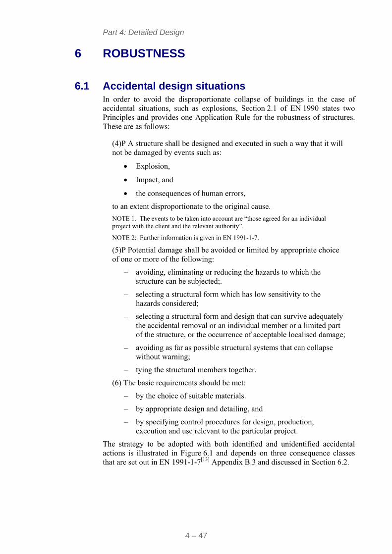
Part 4: Detailed Design
4 – 47
6 ROBUSTNESS
6.1 Accidental design situations In order to avoid the disproportionate collapse of buildings in the case of accidental situations, such as explosions, Section 2.1 of EN 1990 states two Principles and provides one Application Rule for the robustness of structures. These are as follows:
(4)P A structure shall be designed and executed in such a way that it will not be damaged by events such as:
Explosion,
Impact, and
the consequences of human errors,
to an extent disproportionate to the original cause.
NOTE 1. The events to be taken into account are “those agreed for an individual project with the client and the relevant authority”.
NOTE 2: Further information is given in EN 1991-1-7.
(5)P Potential damage shall be avoided or limited by appropriate choice of one or more of the following:
– avoiding, eliminating or reducing the hazards to which the structure can be subjected;.
– selecting a structural form which has low sensitivity to the hazards considered;
– selecting a structural form and design that can survive adequately the accidental removal or an individual member or a limited part of the structure, or the occurrence of acceptable localised damage;
– avoiding as far as possible structural systems that can collapse without warning;
– tying the structural members together.
(6) The basic requirements should be met:
– by the choice of suitable materials.
– by appropriate design and detailing, and
– by specifying control procedures for design, production, execution and use relevant to the particular project.
The strategy to be adopted with both identified and unidentified accidental actions is illustrated in Figure 6.1 and depends on three consequence classes that are set out in EN 1991-1-7[13] Appendix B.3 and discussed in Section 6.2.
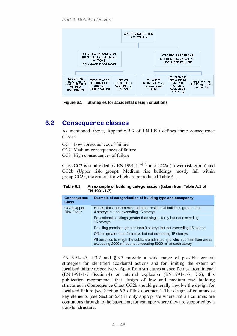
Part 4: Detailed Design
4 – 48
Figure 6.1 Strategies for accidental design situations
6.2 Consequence classes As mentioned above, Appendix B.3 of EN 1990 defines three consequence classes:
CC1 Low consequences of failure CC2 Medium consequences of failure CC3 High consequences of failure
Class CC2 is subdivided by EN 1991-1-7[13] into CC2a (Lower risk group) and CC2b (Upper risk group). Medium rise buildings mostly fall within group CC2b, the criteria for which are reproduced Table 6.1.
Table 6.1 An example of building categorisation (taken from Table A.1 of EN 1991-1-7)
Consequence Class
Example of categorisation of building type and occupancy
Hotels, flats, apartments and other residential buildings greater than 4 storeys but not exceeding 15 storeys
Educational buildings greater than single storey but not exceeding 15 storeys
Retailing premises greater than 3 storeys but not exceeding 15 storeys
Offices greater than 4 storeys but not exceeding 15 storeys
CC2b Upper Risk Group
All buildings to which the public are admitted and which contain floor areas exceeding 2000 m2 but not exceeding 5000 m2 at each storey
EN 1991-1-7, § 3.2 and § 3.3 provide a wide range of possible general strategies for identified accidental actions and for limiting the extent of localised failure respectively. Apart from structures at specific risk from impact (EN 1991-1-7 Section 4) or internal explosion (EN 1991-1-7, § 5), this publication recommends that design of low and medium rise building structures in Consequence Class CC2b should generally involve the design for localised failure (see Section 6.3 of this document). The design of columns as key elements (see Section 6.4) is only appropriate where not all columns are continuous through to the basement; for example where they are supported by a transfer structure.
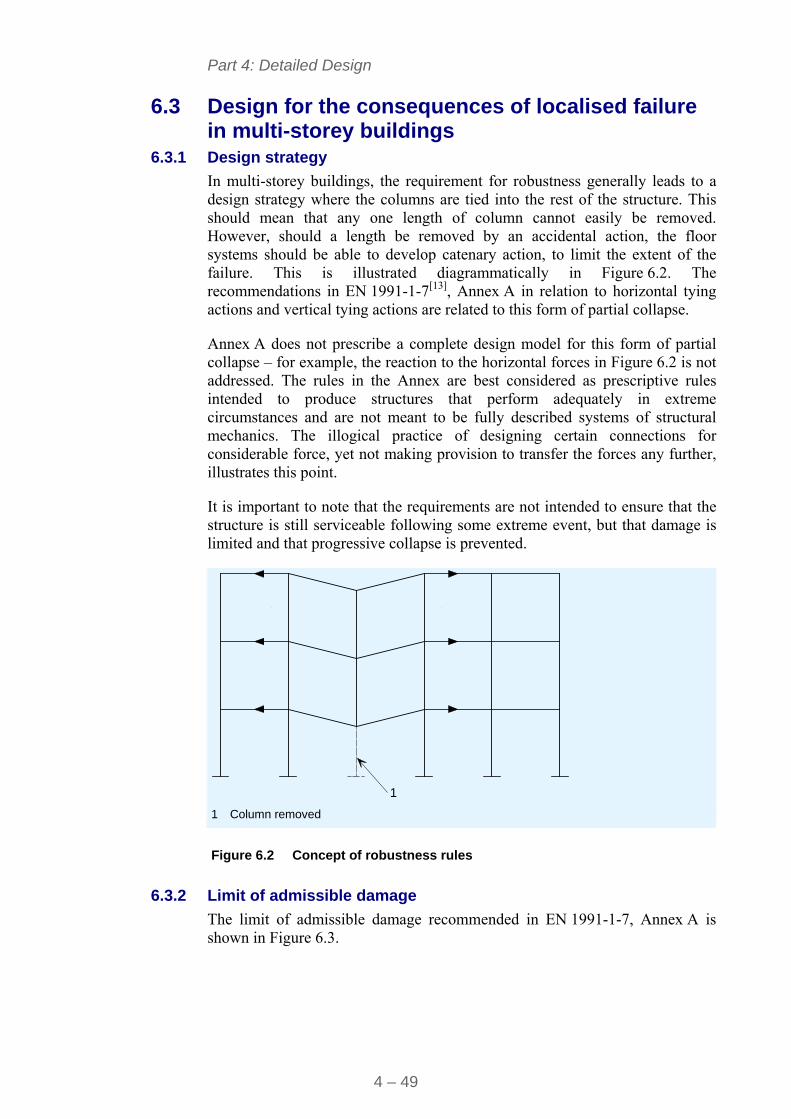
Part 4: Detailed Design
4 – 49
6.3 Design for the consequences of localised failure in multi-storey buildings
6.3.1 Design strategy
In multi-storey buildings, the requirement for robustness generally leads to a design strategy where the columns are tied into the rest of the structure. This should mean that any one length of column cannot easily be removed. However, should a length be removed by an accidental action, the floor systems should be able to develop catenary action, to limit the extent of the failure. This is illustrated diagrammatically in Figure 6.2. The recommendations in EN 1991-1-7[13], Annex A in relation to horizontal tying actions and vertical tying actions are related to this form of partial collapse.
Annex A does not prescribe a complete design model for this form of partial collapse – for example, the reaction to the horizontal forces in Figure 6.2 is not addressed. The rules in the Annex are best considered as prescriptive rules intended to produce structures that perform adequately in extreme circumstances and are not meant to be fully described systems of structural mechanics. The illogical practice of designing certain connections for considerable force, yet not making provision to transfer the forces any further, illustrates this point.
It is important to note that the requirements are not intended to ensure that the structure is still serviceable following some extreme event, but that damage is limited and that progressive collapse is prevented.
1 1 Column removed
Figure 6.2 Concept of robustness rules
6.3.2 Limit of admissible damage
The limit of admissible damage recommended in EN 1991-1-7, Annex A is shown in Figure 6.3.
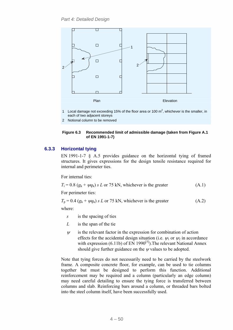
Part 4: Detailed Design
4 – 50
1
22
Plan Elevation
1 Local damage not exceeding 15% of the floor area or 100 m2, whichever is the smaller, in
each of two adjacent storeys 2 Notional column to be removed
Figure 6.3 Recommended limit of admissible damage (taken from Figure A.1 of EN 1991-1-7)
6.3.3 Horizontal tying
EN 1991-1-7 § A.5 provides guidance on the horizontal tying of framed structures. It gives expressions for the design tensile resistance required for internal and perimeter ties.
For internal ties:
Ti = 0.8 (gk + qk) s L or 75 kN, whichever is the greater (A.1)
For perimeter ties:
Tp = 0.4 (gk + qk) s L or 75 kN, whichever is the greater (A.2)
where:
s is the spacing of ties
L is the span of the tie
is the relevant factor in the expression for combination of action effects for the accidental design situation (i.e. 1 or 2 in accordance with expression (6.11b) of EN 1990[5]).The relevant National Annex should give further guidance on the values to be adopted.
Note that tying forces do not necessarily need to be carried by the steelwork frame. A composite concrete floor, for example, can be used to tie columns together but must be designed to perform this function. Additional reinforcement may be required and a column (particularly an edge column) may need careful detailing to ensure the tying force is transferred between columns and slab. Reinforcing bars around a column, or threaded bars bolted into the steel column itself, have been successfully used.
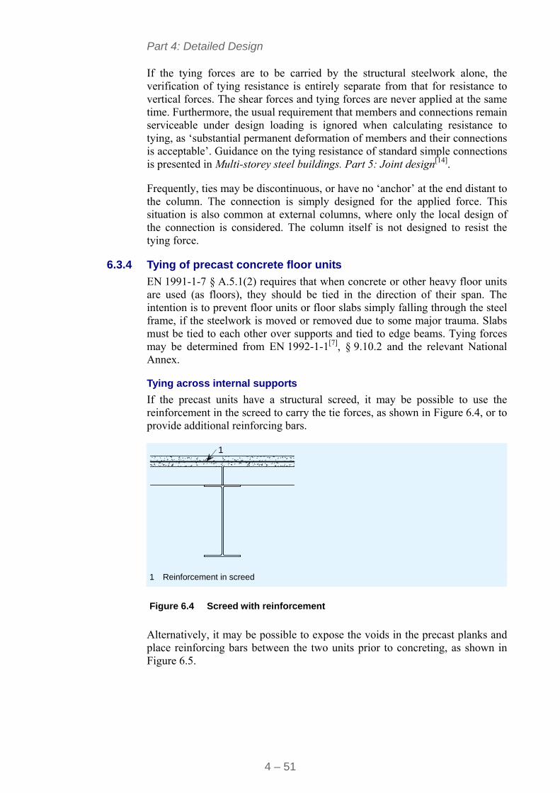
Part 4: Detailed Design
4 – 51
If the tying forces are to be carried by the structural steelwork alone, the verification of tying resistance is entirely separate from that for resistance to vertical forces. The shear forces and tying forces are never applied at the same time. Furthermore, the usual requirement that members and connections remain serviceable under design loading is ignored when calculating resistance to tying, as ‘substantial permanent deformation of members and their connections is acceptable’. Guidance on the tying resistance of standard simple connections is presented in Multi-storey steel buildings. Part 5: Joint design[14].
Frequently, ties may be discontinuous, or have no ‘anchor’ at the end distant to the column. The connection is simply designed for the applied force. This situation is also common at external columns, where only the local design of the connection is considered. The column itself is not designed to resist the tying force.
6.3.4 Tying of precast concrete floor units
EN 1991-1-7 § A.5.1(2) requires that when concrete or other heavy floor units are used (as floors), they should be tied in the direction of their span. The intention is to prevent floor units or floor slabs simply falling through the steel frame, if the steelwork is moved or removed due to some major trauma. Slabs must be tied to each other over supports and tied to edge beams. Tying forces may be determined from EN 1992-1-1[7], § 9.10.2 and the relevant National Annex.
Tying across internal supports
If the precast units have a structural screed, it may be possible to use the reinforcement in the screed to carry the tie forces, as shown in Figure 6.4, or to provide additional reinforcing bars.
1
1 Reinforcement in screed
Figure 6.4 Screed with reinforcement
Alternatively, it may be possible to expose the voids in the precast planks and place reinforcing bars between the two units prior to concreting, as shown in Figure 6.5.
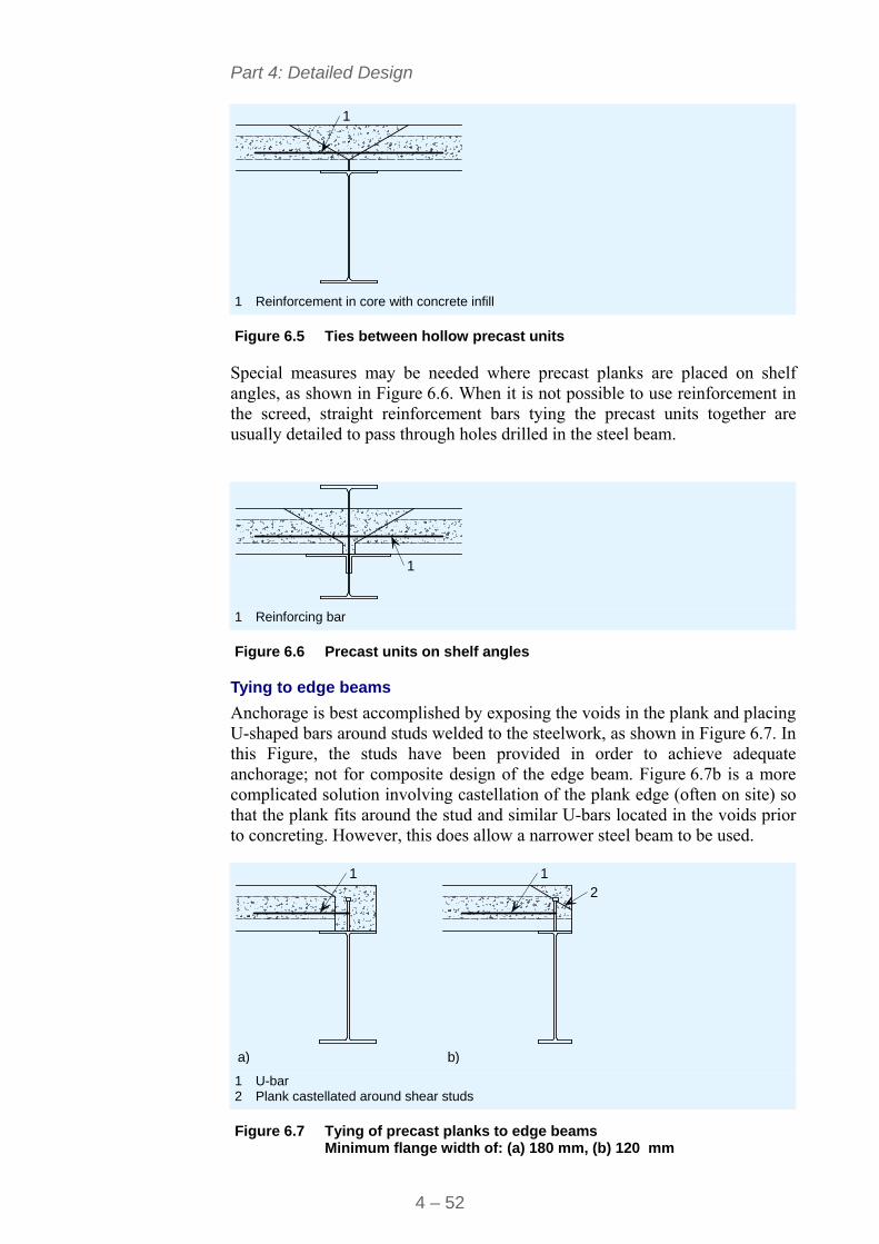
Part 4: Detailed Design
4 – 52
1
1 Reinforcement in core with concrete infill
Figure 6.5 Ties between hollow precast units
Special measures may be needed where precast planks are placed on shelf angles, as shown in Figure 6.6. When it is not possible to use reinforcement in the screed, straight reinforcement bars tying the precast units together are usually detailed to pass through holes drilled in the steel beam.
1
1 Reinforcing bar
Figure 6.6 Precast units on shelf angles
Tying to edge beams
Anchorage is best accomplished by exposing the voids in the plank and placing U-shaped bars around studs welded to the steelwork, as shown in Figure 6.7. In this Figure, the studs have been provided in order to achieve adequate anchorage; not for composite design of the edge beam. Figure 6.7b is a more complicated solution involving castellation of the plank edge (often on site) so that the plank fits around the stud and similar U-bars located in the voids prior to concreting. However, this does allow a narrower steel beam to be used.
1 12
a) b) 1 U-bar 2 Plank castellated around shear studs
Figure 6.7 Tying of precast planks to edge beams
Minimum flange width of: (a) 180 mm, (b) 120 mm
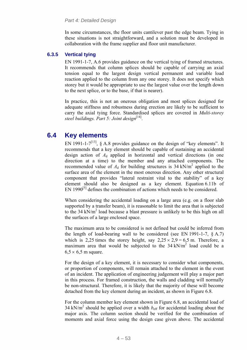
Part 4: Detailed Design
4 – 53
In some circumstances, the floor units cantilever past the edge beam. Tying in these situations is not straightforward, and a solution must be developed in collaboration with the frame supplier and floor unit manufacturer.
6.3.5 Vertical tying
EN 1991-1-7, A.6 provides guidance on the vertical tying of framed structures. It recommends that column splices should be capable of carrying an axial tension equal to the largest design vertical permanent and variable load reaction applied to the column from any one storey. It does not specify which storey but it would be appropriate to use the largest value over the length down to the next splice, or to the base, if that is nearer).
In practice, this is not an onerous obligation and most splices designed for adequate stiffness and robustness during erection are likely to be sufficient to carry the axial tying force. Standardised splices are covered in Multi-storey steel buildings. Part 5: Joint design[14].
6.4 Key elements EN 1991-1-7[13], § A.8 provides guidance on the design of “key elements”. It recommends that a key element should be capable of sustaining an accidental design action of Ad applied in horizontal and vertical directions (in one direction at a time) to the member and any attached components. The recommended value of Ad for building structures is 34 kN/m2 applied to the surface area of the element in the most onerous direction. Any other structural component that provides “lateral restraint vital to the stability” of a key element should also be designed as a key element. Equation 6.11b of EN 1990[5] defines the combination of actions which needs to be considered.
When considering the accidental loading on a large area (e.g. on a floor slab supported by a transfer beam), it is reasonable to limit the area that is subjected to the 34 kN/m2 load because a blast pressure is unlikely to be this high on all the surfaces of a large enclosed space.
The maximum area to be considered is not defined but could be inferred from the length of load-bearing wall to be considered (see EN 1991-1-7, § A.7) which is 2,25 times the storey height, say 2,25 2,9 = 6,5 m. Therefore, a maximum area that would be subjected to the 34 kN/m2 load could be a 6,5 6,5 m square.
For the design of a key element, it is necessary to consider what components, or proportion of components, will remain attached to the element in the event of an incident. The application of engineering judgement will play a major part in this process. For framed construction, the walls and cladding will normally be non-structural. Therefore, it is likely that the majority of these will become detached from the key element during an incident, as shown in Figure 6.8.
For the column member key element shown in Figure 6.8, an accidental load of 34 kN/m2 should be applied over a width beff for accidental loading about the major axis. The column section should be verified for the combination of moments and axial force using the design case given above. The accidental
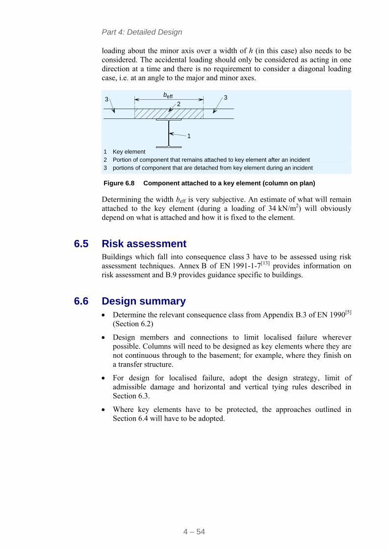
Part 4: Detailed Design
4 – 54
loading about the minor axis over a width of h (in this case) also needs to be considered. The accidental loading should only be considered as acting in one direction at a time and there is no requirement to consider a diagonal loading case, i.e. at an angle to the major and minor axes.
beff3 32
1
1 Key element 2 Portion of component that remains attached to key element after an incident 3 portions of component that are detached from key element during an incident
Figure 6.8 Component attached to a key element (column on plan)
Determining the width beff is very subjective. An estimate of what will remain attached to the key element (during a loading of 34 kN/m2) will obviously depend on what is attached and how it is fixed to the element.
6.5 Risk assessment Buildings which fall into consequence class 3 have to be assessed using risk assessment techniques. Annex B of EN 1991-1-7[13] provides information on risk assessment and B.9 provides guidance specific to buildings.
6.6 Design summary Determine the relevant consequence class from Appendix B.3 of EN 1990[5]
(Section 6.2)
Design members and connections to limit localised failure wherever possible. Columns will need to be designed as key elements where they are not continuous through to the basement; for example, where they finish on a transfer structure.
For design for localised failure, adopt the design strategy, limit of admissible damage and horizontal and vertical tying rules described in Section 6.3.
Where key elements have to be protected, the approaches outlined in Section 6.4 will have to be adopted.
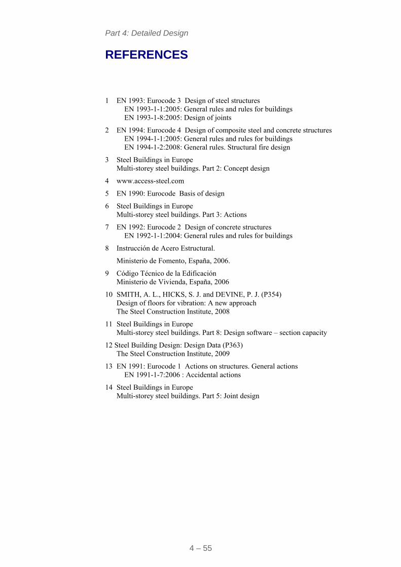
Part 4: Detailed Design
4 – 55
REFERENCES
1 EN 1993: Eurocode 3 Design of steel structures
EN 1993-1-1:2005: General rules and rules for buildings EN 1993-1-8:2005: Design of joints
2 EN 1994: Eurocode 4 Design of composite steel and concrete structures EN 1994-1-1:2005: General rules and rules for buildings EN 1994-1-2:2008: General rules. Structural fire design
3 Steel Buildings in Europe Multi-storey steel buildings. Part 2: Concept design
4 www.access-steel.com
5 EN 1990: Eurocode Basis of design
6 Steel Buildings in Europe Multi-storey steel buildings. Part 3: Actions
7 EN 1992: Eurocode 2 Design of concrete structures EN 1992-1-1:2004: General rules and rules for buildings
8 Instrucción de Acero Estructural.
Ministerio de Fomento, España, 2006.
9 Código Técnico de la Edificación Ministerio de Vivienda, España, 2006
10 SMITH, A. L., HICKS, S. J. and DEVINE, P. J. (P354) Design of floors for vibration: A new approach The Steel Construction Institute, 2008
11 Steel Buildings in Europe Multi-storey steel buildings. Part 8: Design software – section capacity
12 Steel Building Design: Design Data (P363) The Steel Construction Institute, 2009
13 EN 1991: Eurocode 1 Actions on structures. General actions EN 1991-1-7:2006 : Accidental actions
14 Steel Buildings in Europe Multi-storey steel buildings. Part 5: Joint design
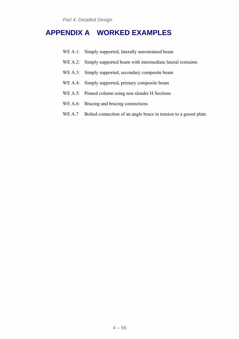
Part 4: Detailed Design
4 – 56
APPENDIX A WORKED EXAMPLES
WE A.1: Simply supported, laterally unrestrained beam
WE A.2: Simply supported beam with intermediate lateral restraints
WE A.3: Simply supported, secondary composite beam
WE A.4: Simply supported, primary composite beam
WE A.5: Pinned column using non slender H Sections
WE A.6: Bracing and bracing connections
WE A.7 Bolted connection of an angle brace in tension to a gusset plate
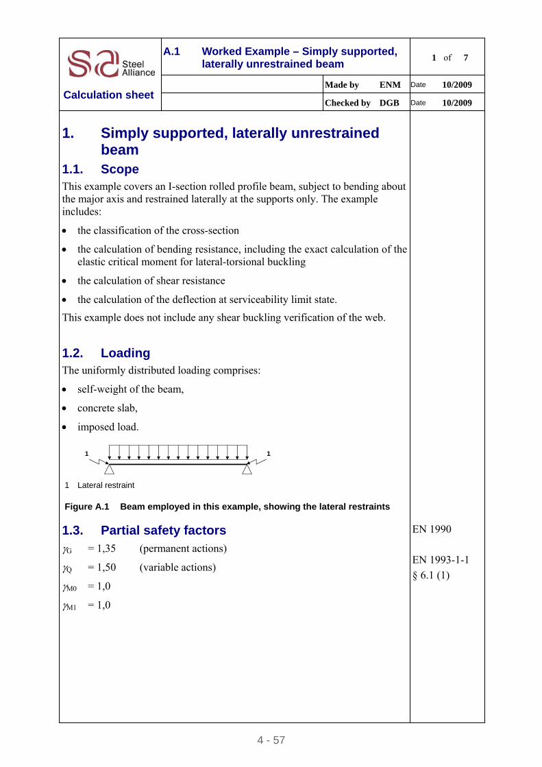
4 - 57
A.1 Worked Example – Simply supported, laterally unrestrained beam
1 of 7
Made by ENM Date 10/2009
Calculation sheet Checked by DGB Date 10/2009
1. Simply supported, laterally unrestrained beam
1.1. Scope
This example covers an I-section rolled profile beam, subject to bending about the major axis and restrained laterally at the supports only. The example includes:
the classification of the cross-section
the calculation of bending resistance, including the exact calculation of the elastic critical moment for lateral-torsional buckling
the calculation of shear resistance
the calculation of the deflection at serviceability limit state.
This example does not include any shear buckling verification of the web.
1.2. Loading
The uniformly distributed loading comprises:
self-weight of the beam,
concrete slab,
imposed load.
1 1
1 Lateral restraint
Figure A.1 Beam employed in this example, showing the lateral restraints
1.3. Partial safety factors G = 1,35 (permanent actions)
Q = 1,50 (variable actions)
M0 = 1,0
M1 = 1,0
EN 1990
EN 1993-1-1
§ 6.1 (1)
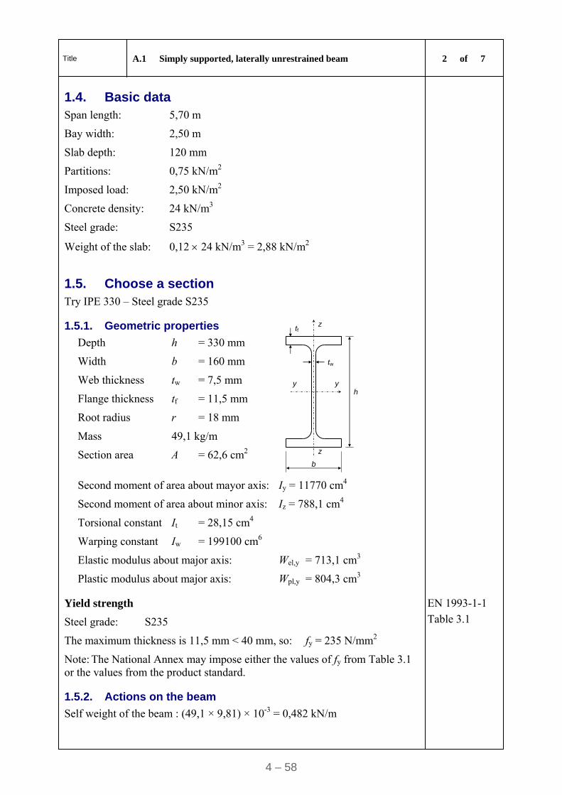
Title A.1 Simply supported, laterally unrestrained beam 2 of 7
4 – 58
1.4. Basic data Span length: 5,70 m
Bay width: 2,50 m
Slab depth: 120 mm
Partitions: 0,75 kN/m2
Imposed load: 2,50 kN/m2
Concrete density: 24 kN/m3
Steel grade: S235
Weight of the slab: 0,12 24 kN/m3 = 2,88 kN/m2
1.5. Choose a section Try IPE 330 – Steel grade S235
1.5.1. Geometric properties
Depth h = 330 mm
Width b = 160 mm
Web thickness tw = 7,5 mm
Flange thickness tf = 11,5 mm
Root radius r = 18 mm
Mass 49,1 kg/m
Section area A = 62,6 cm2
z
z
y y
tf
tw
b
h
Second moment of area about mayor axis: Iy = 11770 cm4
Second moment of area about minor axis: Iz = 788,1 cm4
Torsional constant It = 28,15 cm4
Warping constant Iw = 199100 cm6
Elastic modulus about major axis: Wel,y = 713,1 cm3
Plastic modulus about major axis: Wpl,y = 804,3 cm3
Yield strength
Steel grade: S235
The maximum thickness is 11,5 mm < 40 mm, so: fy = 235 N/mm2
Note: The National Annex may impose either the values of fy from Table 3.1 or the values from the product standard.
EN 1993-1-1
Table 3.1
1.5.2. Actions on the beam
Self weight of the beam : (49,1 × 9,81) × 10-3 = 0,482 kN/m
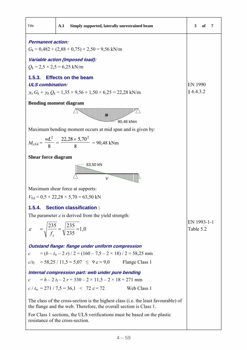
Title A.1 Simply supported, laterally unrestrained beam 3 of 7
4 – 59
Permanent action:
Gk = 0,482 + (2,88 + 0,75) × 2,50 = 9,56 kN/m
Variable action (Imposed load):
Qk = 2,5 × 2,5 = 6,25 kN/m
1.5.3. Effects on the beam
ULS combination:
G Gk + Q Qk = 1,35 × 9,56 + 1,50 × 6,25 = 22,28 kN/m
EN 1990
§ 6.4.3.2
Bending moment diagram
M
90,48 kNm
Maximum bending moment occurs at mid span and is given by:
My,Ed = 8
2wL =
870,528,22 2
= 90,48 kNm
Shear force diagram
V
63,50 kN
Maximum shear force at supports:
VEd = 0,5 × 22,28 × 5,70 = 63,50 kN
1.5.4. Section classification :
The parameter is derived from the yield strength:
1,0235
235
235
y
f
EN 1993-1-1
Table 5.2
Outstand flange: flange under uniform compression
c = (b – tw – 2 r) / 2 = (160 – 7,5 – 2 × 18) / 2 = 58,25 mm
c/tf = 58,25 / 11,5 = 5,07 ≤ 9 = 9,0 Flange Class 1
Internal compression part: web under pure bending
c = h – 2 tf – 2 r = 330 – 2 × 11,5 – 2 × 18 = 271 mm
c / tw = 271 / 7,5 = 36,1 < 72 = 72 Web Class 1
The class of the cross-section is the highest class (i.e. the least favourable) of the flange and the web. Therefore, the overall section is Class 1.
For Class 1 sections, the ULS verifications must be based on the plastic resistance of the cross-section.
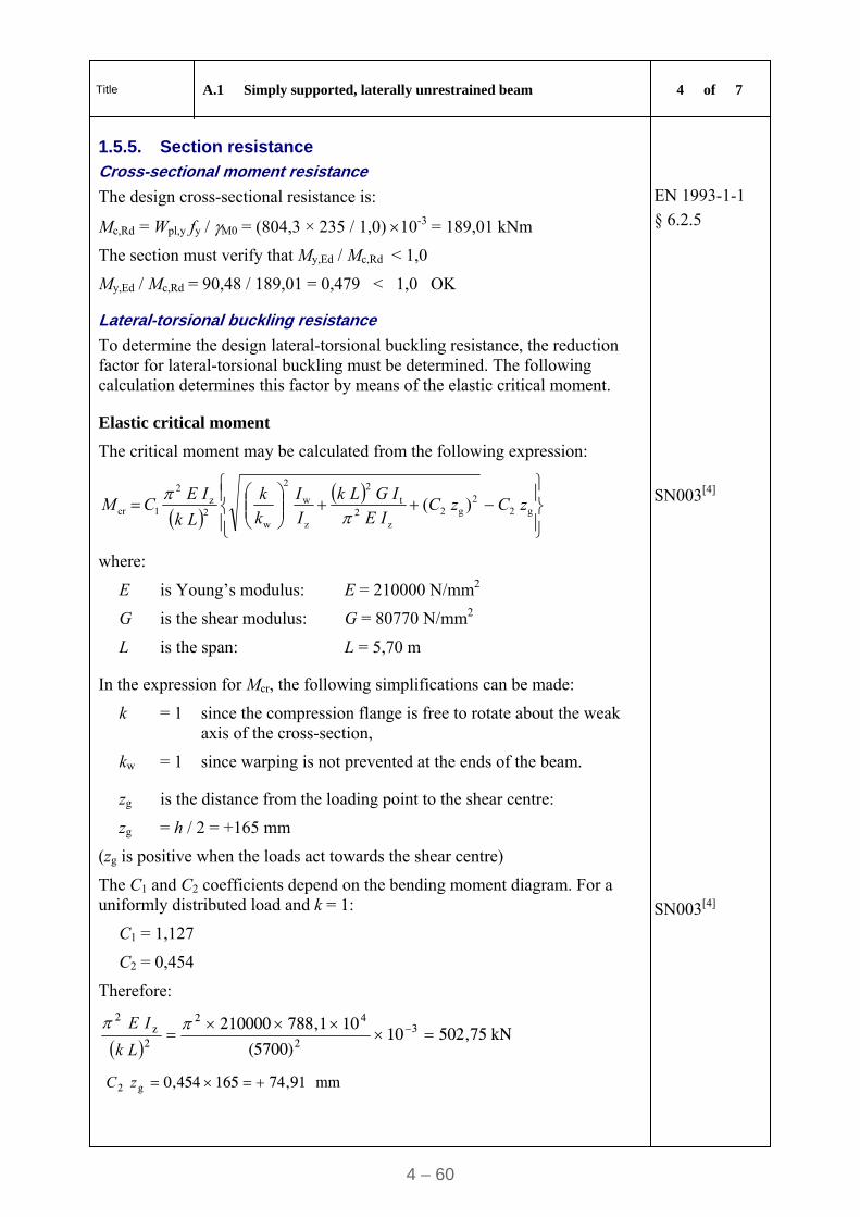
Title A.1 Simply supported, laterally unrestrained beam 4 of 7
4 – 60
1.5.5. Section resistance
Cross-sectional moment resistance
The design cross-sectional resistance is:
Mc,Rd = Wpl,y fy / M0 = (804,3 × 235 / 1,0) 10-3 = 189,01 kNm
The section must verify that My,Ed / Mc,Rd < 1,0
My,Ed / Mc,Rd = 90,48 / 189,01 = 0,479 < 1,0 OK
EN 1993-1-1
§ 6.2.5
Lateral-torsional buckling resistance
To determine the design lateral-torsional buckling resistance, the reduction factor for lateral-torsional buckling must be determined. The following calculation determines this factor by means of the elastic critical moment.
Elastic critical moment
The critical moment may be calculated from the following expression:
g2
2g2
z2
t2
z
w
2
w2
z2
1cr ) (
zCzC
I E
IGL k
I
I
k
k
L k
I ECM
where:
E is Young’s modulus: E = 210000 N/mm2
G is the shear modulus: G = 80770 N/mm2
L is the span: L = 5,70 m
SN003[4]
In the expression for Mcr, the following simplifications can be made:
k = 1 since the compression flange is free to rotate about the weak axis of the cross-section,
kw = 1 since warping is not prevented at the ends of the beam.
zg is the distance from the loading point to the shear centre:
zg = h / 2 = +165 mm
(zg is positive when the loads act towards the shear centre)
The C1 and C2 coefficients depend on the bending moment diagram. For a uniformly distributed load and k = 1:
C1 = 1,127
C2 = 0,454
SN003[4]
Therefore:
kN 502,7510
(5700)
10788,1 210000 32
42
2z
2
L k
IE
mm 74,91 165 0,454 g2 zC
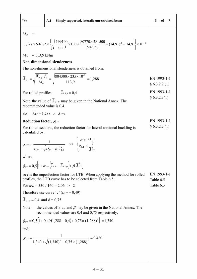
Title A.1 Simply supported, laterally unrestrained beam 5 of 7
4 – 61
Mcr =
502,75 1,127 32 1074,91(74,91) 502750
281500 80770 100
788,1
199100
Mcr = 113,9 kNm
Non-dimensional slenderness
The non-dimensional slenderness is obtained from:
1,288 113,9
10 235 804300
6-
cr
yypl,LT
M
fW
EN 1993-1-1
§ 6.3.2.2 (1)
For rolled profiles: 0,4 LT,0
Note: the value of LT,0 may be given in the National Annex. The recommended value is 0,4.
So LT,0LT 1,288
EN 1993-1-1
§ 6.3.2.3(1)
Reduction factor, LT
For rolled sections, the reduction factor for lateral-torsional buckling is calculated by:
2LT
LT
LT
2LT
2LTLT
LT1
1,0 but
1
where:
1 0,5 LTLT,0LTLTLT
2
EN 1993-1-1
§ 6.3.2.3 (1)
LT is the imperfection factor for LTB. When applying the method for rolled profiles, the LTB curve has to be selected from Table 6.5:
For h/b = 330 / 160 = 2,06 > 2
Therefore use curve ‘c’ (LT = 0,49)
0,4 LT,0 and = 0,75
Note: the values of LT,0 and may be given in the National Annex. The recommended values are 0,4 and 0,75 respectively.
EN 1993-1-1
Table 6.5
Table 6.3
1,340 (1,288)0,75 0,41,288 0,49 1 0,5 2LT
and:
0,480 (1,288)0,75(1,340) 1,340
1
22LT
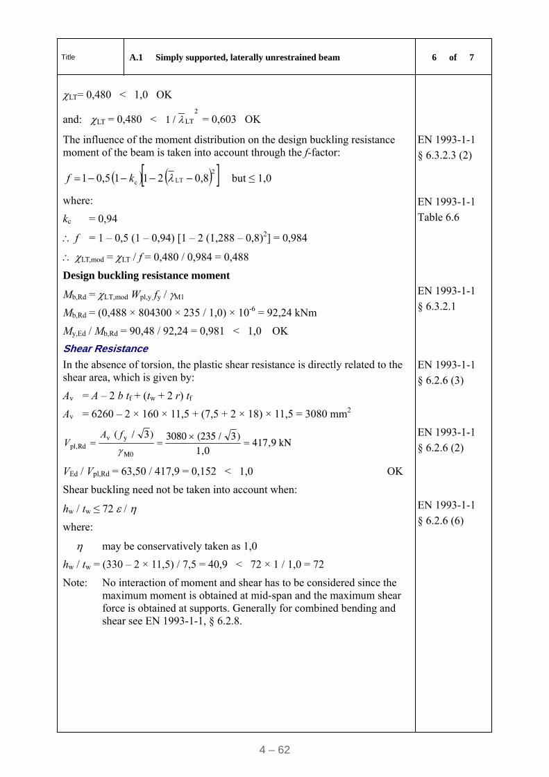
Title A.1 Simply supported, laterally unrestrained beam 6 of 7
4 – 62
LT= 0,480 < 1,0 OK
and: LT = 0,480 < 2
LT / 1 = 0,603 OK
The influence of the moment distribution on the design buckling resistance moment of the beam is taken into account through the f-factor:
2LTc 0,8 2 1 1 0,5 1 kf but ≤ 1,0
where:
kc = 0,94
f = 1 – 0,5 (1 – 0,94) [1 – 2 (1,288 – 0,8)2] = 0,984
EN 1993-1-1
§ 6.3.2.3 (2)
EN 1993-1-1
Table 6.6
LT,mod = LT / f = 0,480 / 0,984 = 0,488
Design buckling resistance moment
Mb,Rd = LT,mod Wpl,y fy / M1
Mb,Rd = (0,488 × 804300 × 235 / 1,0) × 10-6 = 92,24 kNm
My,Ed / Mb,Rd = 90,48 / 92,24 = 0,981 < 1,0 OK
EN 1993-1-1
§ 6.3.2.1
Shear Resistance
In the absence of torsion, the plastic shear resistance is directly related to the shear area, which is given by:
Av = A – 2 b tf + (tw + 2 r) tf
Av = 6260 – 2 × 160 × 11,5 + (7,5 + 2 × 18) × 11,5 = 3080 mm2
EN 1993-1-1
§ 6.2.6 (3)
kN 417,9 1,0
)3 / (2353080
)3 / (
M0
yvRdpl,
fA
V
VEd / Vpl,Rd = 63,50 / 417,9 = 0,152 < 1,0 OK
EN 1993-1-1
§ 6.2.6 (2)
Shear buckling need not be taken into account when:
hw / tw ≤ 72 /
where:
may be conservatively taken as 1,0
hw / tw = (330 – 2 × 11,5) / 7,5 = 40,9 < 72 × 1 / 1,0 = 72
EN 1993-1-1
§ 6.2.6 (6)
Note: No interaction of moment and shear has to be considered since the maximum moment is obtained at mid-span and the maximum shear force is obtained at supports. Generally for combined bending and shear see EN 1993-1-1, § 6.2.8.
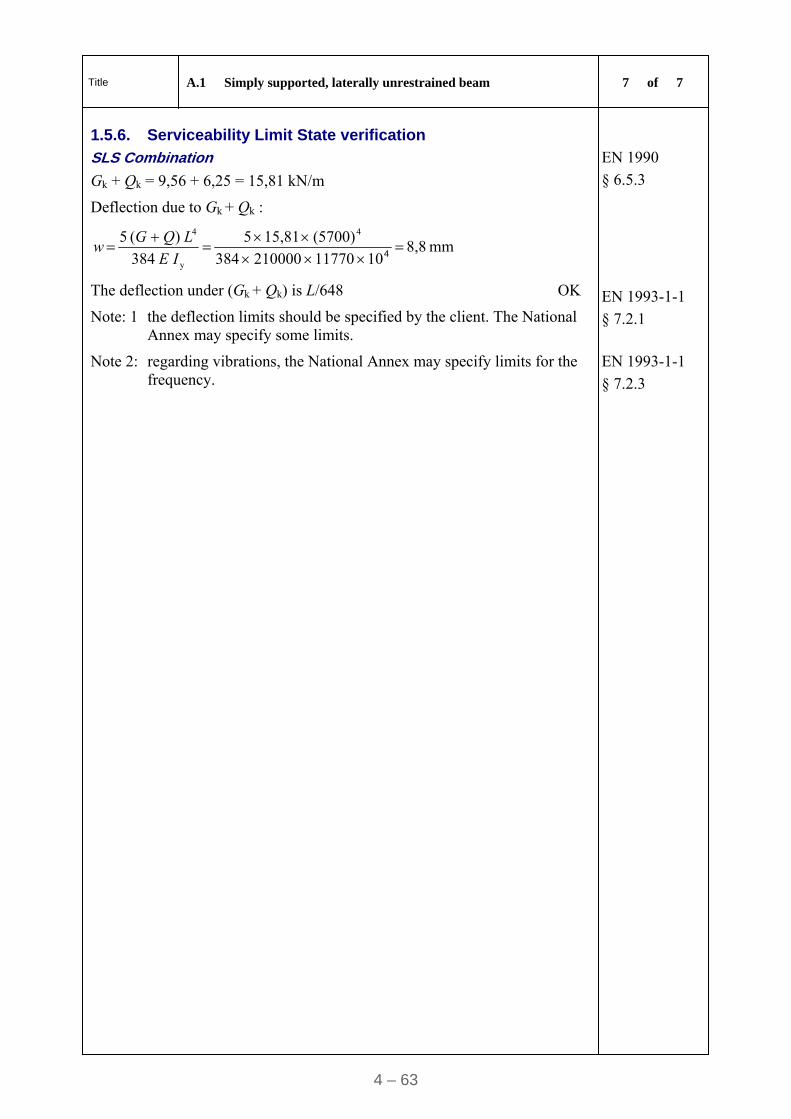
Title A.1 Simply supported, laterally unrestrained beam 7 of 7
4 – 63
1.5.6. Serviceability Limit State verification
SLS Combination
Gk + Qk = 9,56 + 6,25 = 15,81 kN/m
EN 1990
§ 6.5.3
Deflection due to Gk + Qk :
mm 8,8 1011770210000384
(5700)15,815
384
)( 5
4
y
4
4IE
LQGw
The deflection under (Gk + Qk) is L/648 OK
Note: 1 the deflection limits should be specified by the client. The National Annex may specify some limits.
EN 1993-1-1
§ 7.2.1
Note 2: regarding vibrations, the National Annex may specify limits for the frequency.
EN 1993-1-1
§ 7.2.3
4 - 64
A.2 Worked Example – Simply supported beam with intermediate lateral restraints
1 of 7
Made by CZT Date 06/2009
Calculation sheet Checked by ENM Date 07/2009
2. Simply Supported Beam with Intermediate Lateral Restraints
2.1. Scope This example deals with a simply supported roof beam, with intermediate lateral restraints, under a uniformly distributed load:
self-weight of the beam
roofing with purlins
climatic loads.
The beam is a rolled I-profile in bending about the strong axis.
This example includes:
the classification of the cross-section
the calculation of bending resistance
the calculation of shear resistance
the calculation of the deflection at serviceability limit state.
2.2. Partial safety factor G,sup = 1,35 (permanent loads)
G,inf = 1,0 (permanent loads)
Q = 1,50 (variable loads)
M0 = 1,0
M1 = 1,0
EN 1990
Table A1.2(B)
EN 1993-1-1
§ 6.1 (1)
2.3. Basic data Span length: 15,00 m
Bay width: 6,00 m
Roof: 0,30 kN/m2
Climatic load: Snow 0,60 kN/m2
Climatic load: Wind - 0,50 kN/m2 (suction)
Steel grade: S235
The climatic loads are characteristic values assumed to have been calculated according to EN 1991.
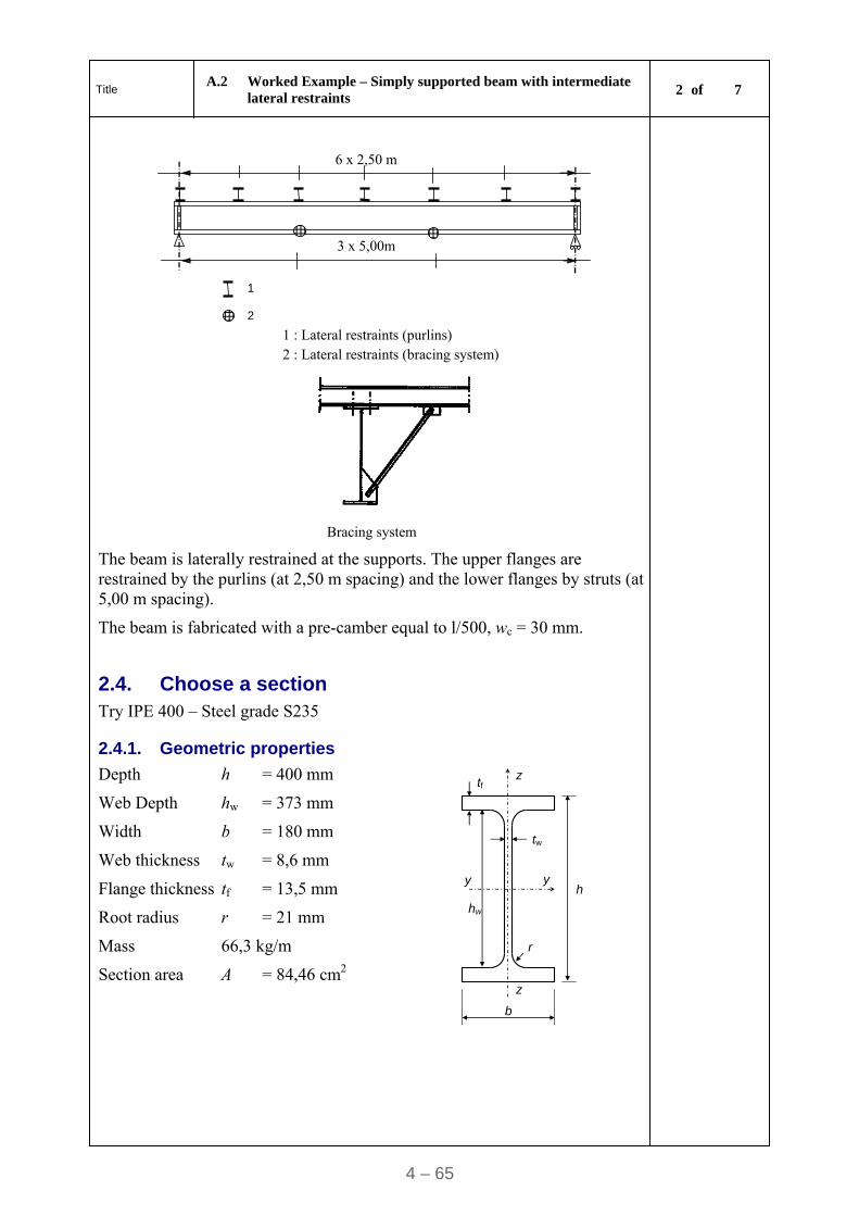
Title A.2 Worked Example – Simply supported beam with intermediate
lateral restraints 2 of 7
4 – 65
1 2
3 x 5,00m
6 x 2,50 m
1 : Lateral restraints (purlins) 2 : Lateral restraints (bracing system)
Bracing system
The beam is laterally restrained at the supports. The upper flanges are restrained by the purlins (at 2,50 m spacing) and the lower flanges by struts (at 5,00 m spacing).
The beam is fabricated with a pre-camber equal to l/500, wc = 30 mm.
2.4. Choose a section
Try IPE 400 – Steel grade S235
2.4.1. Geometric properties
Depth h = 400 mm
Web Depth hw = 373 mm
Width b = 180 mm
Web thickness tw = 8,6 mm
Flange thickness tf = 13,5 mm
Root radius r = 21 mm
Mass 66,3 kg/m
Section area A = 84,46 cm2
hw
y y
r
z
z
tf
tw
b
h
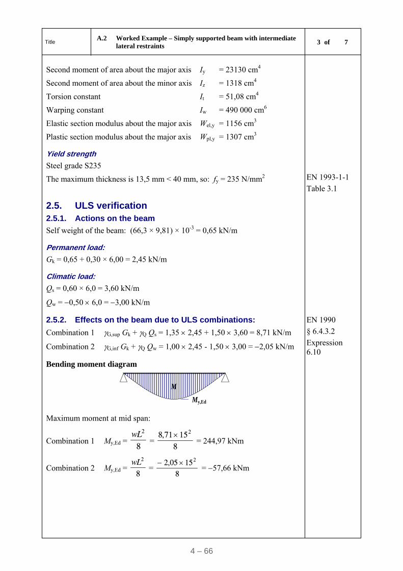
Title A.2 Worked Example – Simply supported beam with intermediate
lateral restraints 3 of 7
4 – 66
Second moment of area about the major axis Iy = 23130 cm4
Second moment of area about the minor axis Iz = 1318 cm4
Torsion constant It = 51,08 cm4
Warping constant Iw = 490 000 cm6
Elastic section modulus about the major axis Wel,y = 1156 cm3
Plastic section modulus about the major axis Wpl,y = 1307 cm3
Yield strength
Steel grade S235
The maximum thickness is 13,5 mm < 40 mm, so: fy = 235 N/mm2
EN 1993-1-1
Table 3.1
2.5. ULS verification 2.5.1. Actions on the beam
Self weight of the beam: (66,3 × 9,81) × 10-3 = 0,65 kN/m
Permanent load:
Gk = 0,65 + 0,30 × 6,00 = 2,45 kN/m
Climatic load:
Qs = 0,60 × 6,0 = 3,60 kN/m
Qw = 0,50 6,0 = 3,00 kN/m
2.5.2. Effects on the beam due to ULS combinations:
Combination 1 G,sup Gk + Q Qs = 1,35 2,45 + 1,50 3,60 = 8,71 kN/m
Combination 2 G,inf Gk + Q Qw = 1,00 2,45 - 1,50 3,00 = 2,05 kN/m
EN 1990
§ 6.4.3.2
Expression 6.10
Bending moment diagram
M
My,Ed
Maximum moment at mid span:
Combination 1 My,Ed = 8
2wL =
81571,8 2
= 244,97 kNm
Combination 2 My,Ed = 8
2wL =
81505,2 2
= 57,66 kNm
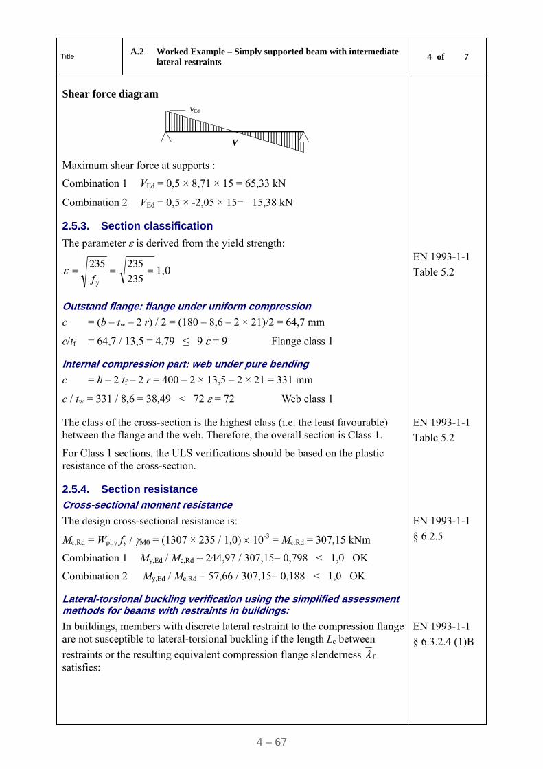
Title A.2 Worked Example – Simply supported beam with intermediate
lateral restraints 4 of 7
4 – 67
Shear force diagram
V
VEd
Maximum shear force at supports :
Combination 1 VEd = 0,5 × 8,71 × 15 = 65,33 kN
Combination 2 VEd = 0,5 × -2,05 × 15= 15,38 kN
2.5.3. Section classification
The parameter is derived from the yield strength:
1,0 235235
235
y
f
EN 1993-1-1
Table 5.2
Outstand flange: flange under uniform compression
c = (b – tw – 2 r) / 2 = (180 – 8,6 – 2 × 21)/2 = 64,7 mm
c/tf = 64,7 / 13,5 = 4,79 ≤ 9 = 9 Flange class 1
Internal compression part: web under pure bending
c = h – 2 tf – 2 r = 400 – 2 × 13,5 – 2 × 21 = 331 mm
c / tw = 331 / 8,6 = 38,49 < 72 = 72 Web class 1
The class of the cross-section is the highest class (i.e. the least favourable) between the flange and the web. Therefore, the overall section is Class 1.
For Class 1 sections, the ULS verifications should be based on the plastic resistance of the cross-section.
EN 1993-1-1
Table 5.2
2.5.4. Section resistance
Cross-sectional moment resistance
The design cross-sectional resistance is:
Mc,Rd = Wpl,y fy / M0 = (1307 × 235 / 1,0) 10-3 = Mc.Rd = 307,15 kNm
EN 1993-1-1
§ 6.2.5
Combination 1 My,Ed / Mc,Rd = 244,97 / 307,15= 0,798 < 1,0 OK
Combination 2 My,Ed / Mc,Rd = 57,66 / 307,15= 0,188 < 1,0 OK
Lateral-torsional buckling verification using the simplified assessment methods for beams with restraints in buildings:
In buildings, members with discrete lateral restraint to the compression flange are not susceptible to lateral-torsional buckling if the length Lc between
restraints or the resulting equivalent compression flange slenderness f satisfies:
EN 1993-1-1
§ 6.3.2.4 (1)B
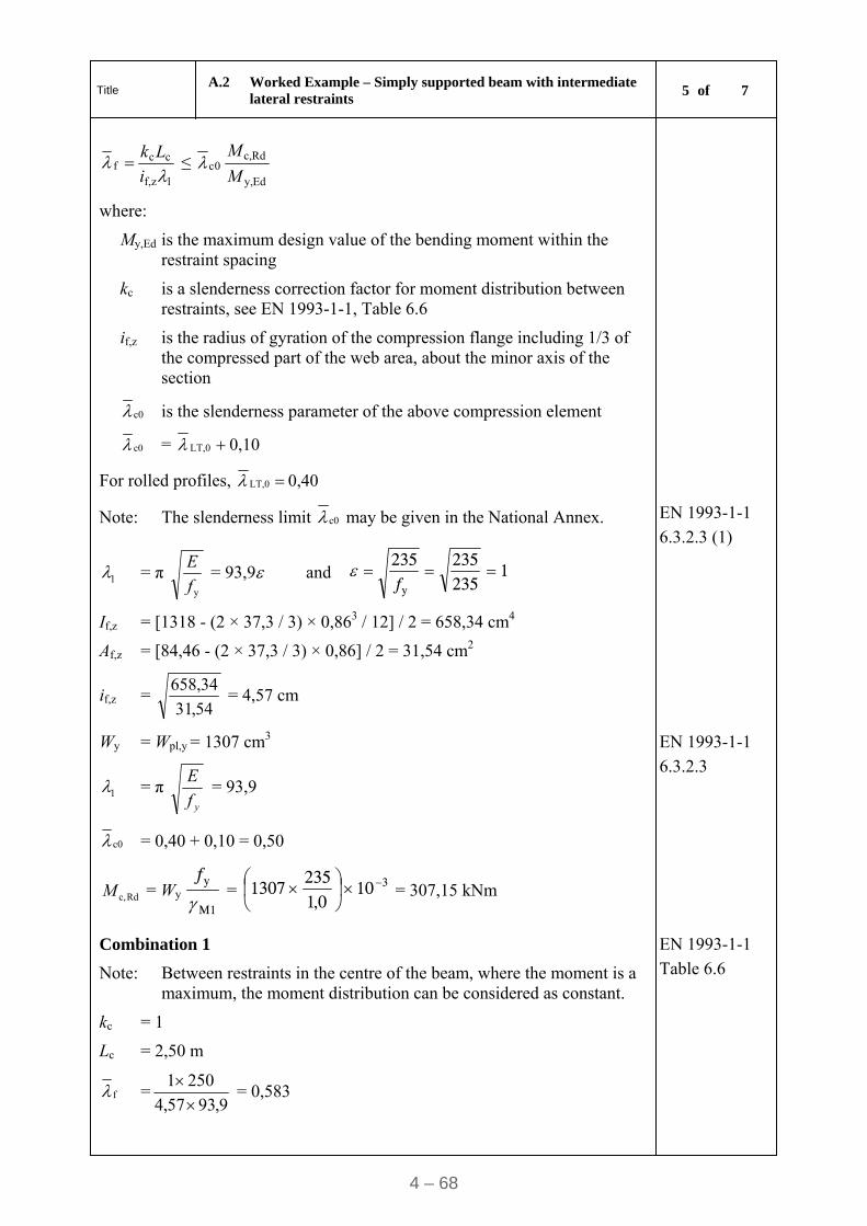
Title A.2 Worked Example – Simply supported beam with intermediate
lateral restraints 5 of 7
4 – 68
1zf,
ccf
i
Lk ≤ 0c
Edy,
Rdc,
M
M
where:
My,Ed is the maximum design value of the bending moment within the restraint spacing
kc is a slenderness correction factor for moment distribution between restraints, see EN 1993-1-1, Table 6.6
if,z is the radius of gyration of the compression flange including 1/3 of the compressed part of the web area, about the minor axis of the section
c0 is the slenderness parameter of the above compression element
c0 = 0,10 LT,0
For rolled profiles, 0,40 LT,0
Note: The slenderness limit c0 may be given in the National Annex.
1 = π yf
E = 93,9 and 1
235235
235
y
f
EN 1993-1-1
6.3.2.3 (1)
If,z = [1318 - (2 × 37,3 / 3) × 0,863 / 12] / 2 = 658,34 cm4
Af,z = [84,46 - (2 × 37,3 / 3) × 0,86] / 2 = 31,54 cm2
if,z = 54,31
34,658 = 4,57 cm
Wy = Wpl,y = 1307 cm3
1 = π yf
E = 93,9
EN 1993-1-1
6.3.2.3
c0 = 0,40 + 0,10 = 0,50
Rdc,M = Wy M1
y
f
= 310
0,1235
1307
= 307,15 kNm
Combination 1
Note: Between restraints in the centre of the beam, where the moment is a maximum, the moment distribution can be considered as constant.
EN 1993-1-1
Table 6.6
kc = 1
Lc = 2,50 m
f =9,9357,4
2501
= 0,583
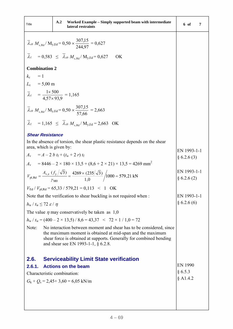
Title A.2 Worked Example – Simply supported beam with intermediate
lateral restraints 6 of 7
4 – 69
c0 Rdc,M / My,Ed = 0,50 97,244
15,307 = 0,627
f = 0,583 ≤ c0 Rdc,M / My,Ed = 0,627 OK
Combination 2
kc = 1
Lc = 5,00 m
f = 9,9357,4
5001
= 1,165
c0 Rdc,M / My,Ed = 0,50 66,57
15,307 = 2,663
f = 1,165 ≤ c0 Rdc,M / My,Ed = 2,663 OK
Shear Resistance
In the absence of torsion, the shear plastic resistance depends on the shear area, which is given by:
Av = A – 2 b tf + (tw + 2 r) tf
EN 1993-1-1
§ 6.2.6 (3)
Av = 8446 – 2 × 180 × 13,5 + (8,6 + 2 × 21) × 13,5 = 4269 mm2
kN 579,21 10001,0
)3235(4269
)3(
M0
yzv,Rdpl,
fA
V EN 1993-1-1
§ 6.2.6 (2)
VEd / Vpl,Rd = 65,33 / 579,21 = 0,113 < 1 OK
Note that the verification to shear buckling is not required when :
hw / tw ≤ 72 /
The value may conservatively be taken as 1,0
hw / tw = (400 – 2 × 13,5) / 8,6 = 43,37 < 72 × 1 / 1,0 = 72
EN 1993-1-1
§ 6.2.6 (6)
Note: No interaction between moment and shear has to be considered, since the maximum moment is obtained at mid-span and the maximum shear force is obtained at supports. Generally for combined bending and shear see EN 1993-1-1, § 6.2.8.
2.6. Serviceability Limit State verification 2.6.1. Actions on the beam
Characteristic combination:
Gk + Qs = 2,45+ 3,60 = 6,05 kN/m
EN 1990
§ 6.5.3
§ A1.4.2
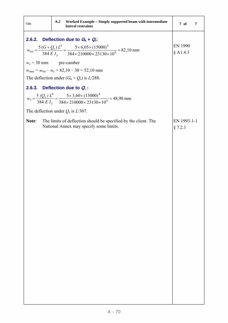
Title A.2 Worked Example – Simply supported beam with intermediate
lateral restraints 7 of 7
4 – 70
2.6.2. Deflection due to Gk + Qs:
mm 82,10 1023130210000384
(15000)6,055
384
)( 5
4
4
y
4s
tot
IE
LQGw
wc = 30 mm pre-camber
wmax = wtot – wc = 82,10 – 30 = 52,10 mm
The deflection under (Gk + Qs) is L/288.
EN 1990
§ A1.4.3
2.6.3. Deflection due to Qs :
mm 48,90 1023130210000384
(15000)3,605
384
5
4
4
y
4
3
I E
) L (Qw s
The deflection under Qs is L/307.
Note: The limits of deflection should be specified by the client. The National Annex may specify some limits.
EN 1993-1-1
§ 7.2.1
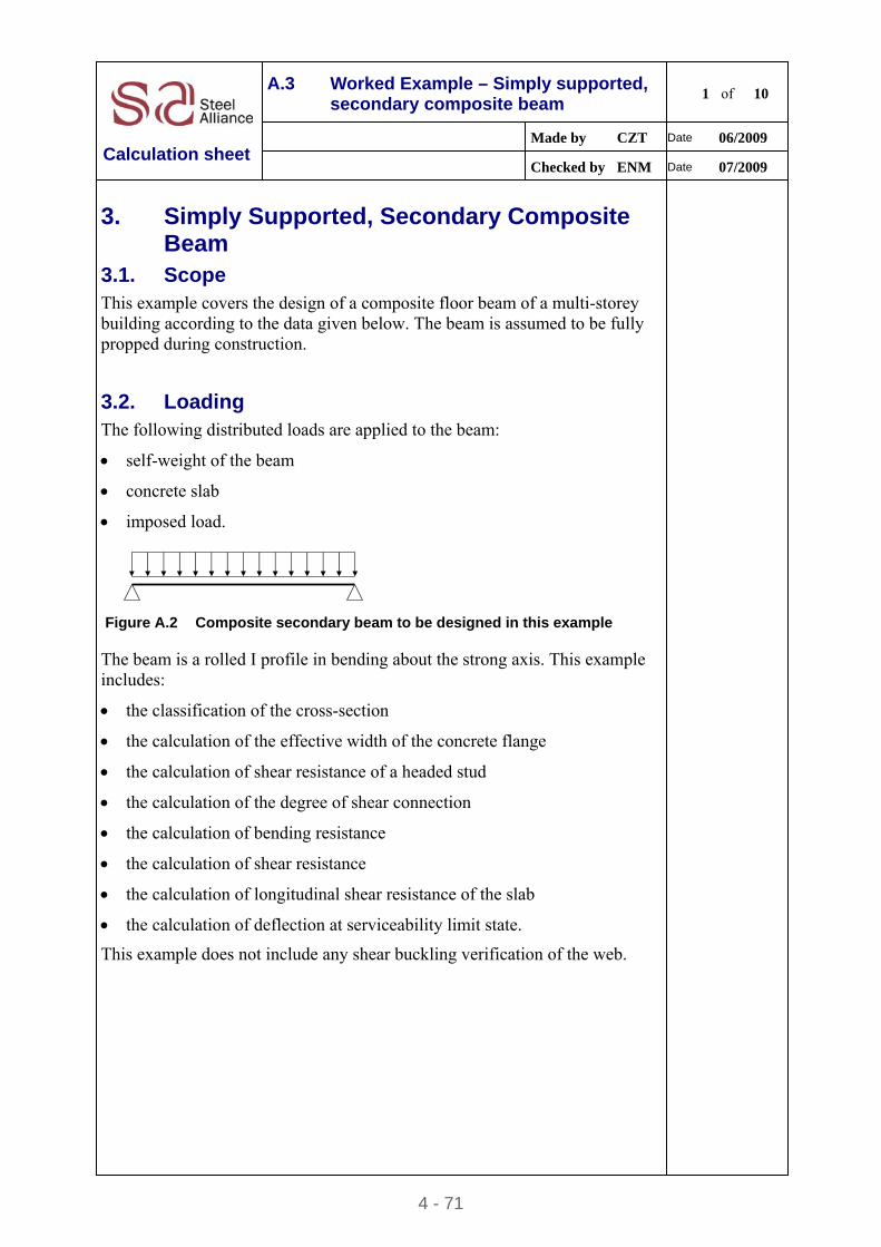
4 - 71
A.3 Worked Example – Simply supported, secondary composite beam
1 of 10
Made by CZT Date 06/2009
Calculation sheet Checked by ENM Date 07/2009
3. Simply Supported, Secondary Composite Beam
3.1. Scope
This example covers the design of a composite floor beam of a multi-storey building according to the data given below. The beam is assumed to be fully propped during construction.
3.2. Loading
The following distributed loads are applied to the beam:
self-weight of the beam
concrete slab
imposed load.
Figure A.2 Composite secondary beam to be designed in this example
The beam is a rolled I profile in bending about the strong axis. This example includes:
the classification of the cross-section
the calculation of the effective width of the concrete flange
the calculation of shear resistance of a headed stud
the calculation of the degree of shear connection
the calculation of bending resistance
the calculation of shear resistance
the calculation of longitudinal shear resistance of the slab
the calculation of deflection at serviceability limit state.
This example does not include any shear buckling verification of the web.
Title A.3 Worked Example – Simply supported, secondary composite
beam 2 of 10
4 – 72
3.3. Partial factors G = 1,35 (permanent loads)
Q = 1,50 (variable loads)
M0 = 1,0
M1 = 1,0
V = 1,25
C = 1,5
EN 1990
EN 1993-1-1 § 6.1 (1)
EN 1994-1-1 § 6.6.3.1
EN 1992-1-1
3.4. Basic data
The profiled steel sheeting is transverse to the beam.
Span length: 7,50 m
Bay width: 3,00 m
Slab depth: 12 cm
Partitions: 0,75 kN/m2
Imposed load: 2,50 kN/m2
Reinforced Concrete density: 25 kN/m3
Steel grade: S355
3.5. Choose section
Try IPE 270
3.5.1. Geometric properties
Depth ha = 270 mm
Width b = 135 mm
Web thickness tw = 6,6 mm
Flange thickness tf = 10,2 mm
Root radius r = 15 mm
Mass 36,1 kg/m
Section area Aa = 45,95 cm2
z
z
y y
tf
tw
b
ha
Second moment of area about the major axis Iy = 5790 cm4
Elastic modulus about the major axis Wel,y = 428,9 cm3
Plastic modulus about the major axis Wpl.y = 484,0 cm3
Modulus of elasticity of steel Ea = 210000 N/mm2
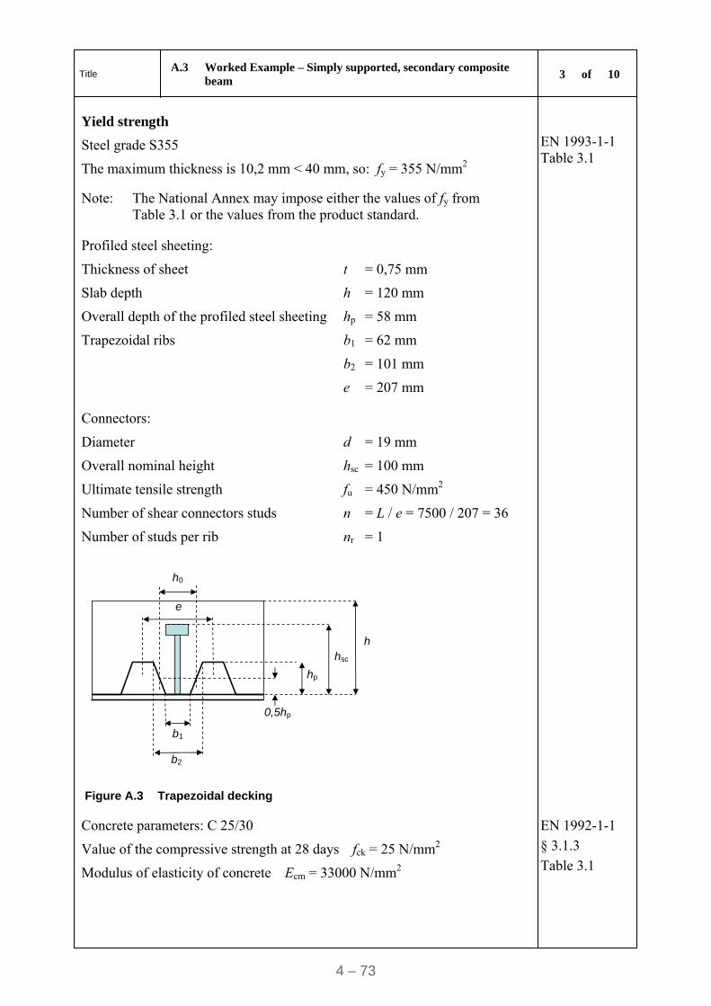
Title A.3 Worked Example – Simply supported, secondary composite
beam 3 of 10
4 – 73
Yield strength
Steel grade S355
The maximum thickness is 10,2 mm < 40 mm, so: fy = 355 N/mm2
EN 1993-1-1 Table 3.1
Note: The National Annex may impose either the values of fy from Table 3.1 or the values from the product standard.
Profiled steel sheeting:
Thickness of sheet t = 0,75 mm
Slab depth h = 120 mm
Overall depth of the profiled steel sheeting hp = 58 mm
Trapezoidal ribs b1 = 62 mm
b2 = 101 mm
e = 207 mm
Connectors:
Diameter d = 19 mm
Overall nominal height hsc = 100 mm
Ultimate tensile strength fu = 450 N/mm2
Number of shear connectors studs n = L / e = 7500 / 207 = 36
Number of studs per rib nr = 1
0,5hp
hp
hsc
h
h0
b1
b2
e
Figure A.3 Trapezoidal decking
Concrete parameters: C 25/30
Value of the compressive strength at 28 days fck = 25 N/mm2
Modulus of elasticity of concrete Ecm = 33000 N/mm2
EN 1992-1-1
§ 3.1.3
Table 3.1
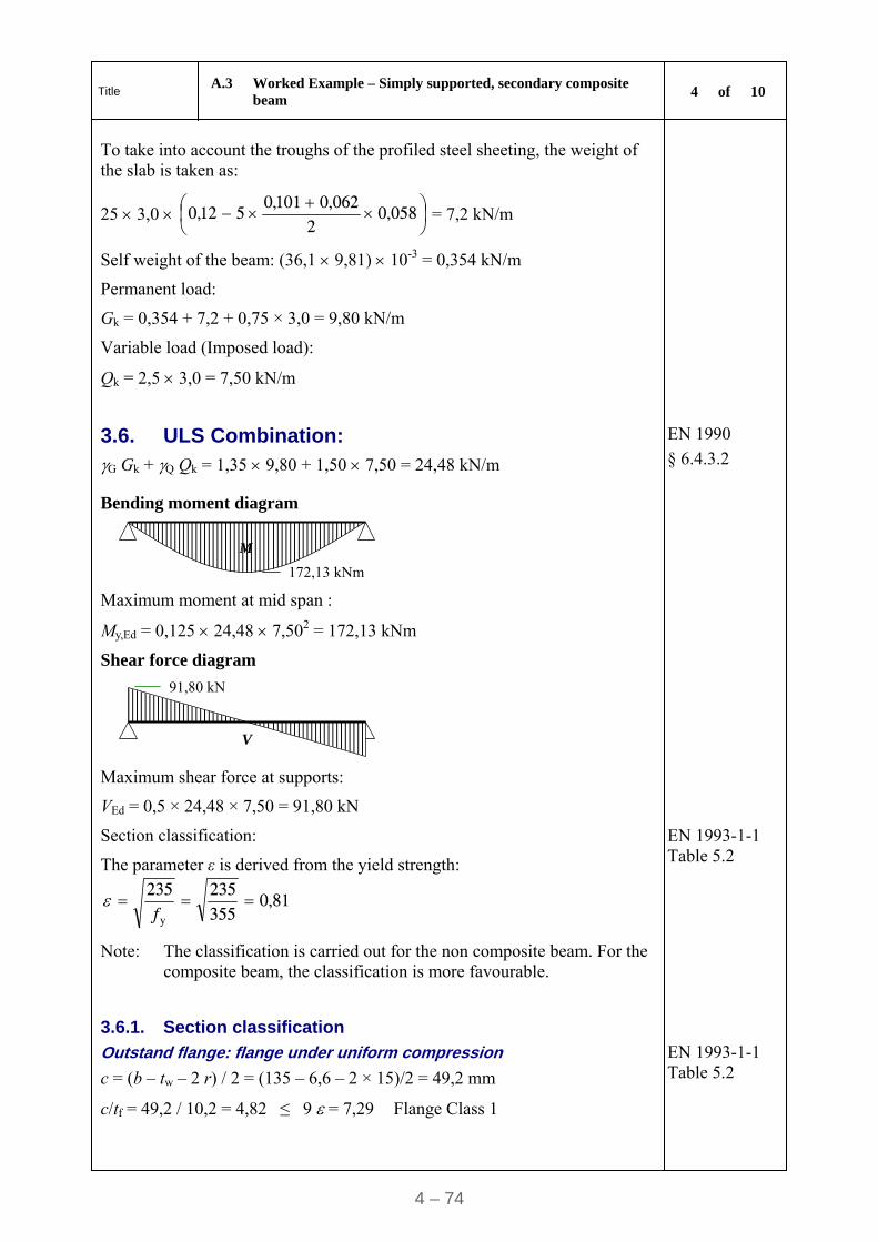
Title A.3 Worked Example – Simply supported, secondary composite
beam 4 of 10
4 – 74
To take into account the troughs of the profiled steel sheeting, the weight of the slab is taken as:
25 3,0
058,0
2062,0101,0
512,0 = 7,2 kN/m
Self weight of the beam: (36,1 9,81) 10-3 = 0,354 kN/m
Permanent load:
Gk = 0,354 + 7,2 + 0,75 × 3,0 = 9,80 kN/m
Variable load (Imposed load):
Qk = 2,5 3,0 = 7,50 kN/m
3.6. ULS Combination: G Gk + Q Qk = 1,35 9,80 + 1,50 7,50 = 24,48 kN/m
EN 1990
§ 6.4.3.2
Bending moment diagram
M
172,13 kNm
Maximum moment at mid span :
My,Ed = 0,125 24,48 7,502 = 172,13 kNm
Shear force diagram
V
91,80 kN
Maximum shear force at supports:
VEd = 0,5 × 24,48 × 7,50 = 91,80 kN
Section classification:
The parameter ε is derived from the yield strength:
81,0355235235
y
f
EN 1993-1-1 Table 5.2
Note: The classification is carried out for the non composite beam. For the composite beam, the classification is more favourable.
3.6.1. Section classification
Outstand flange: flange under uniform compression
c = (b – tw – 2 r) / 2 = (135 – 6,6 – 2 × 15)/2 = 49,2 mm
c/tf = 49,2 / 10,2 = 4,82 ≤ 9 = 7,29 Flange Class 1
EN 1993-1-1 Table 5.2
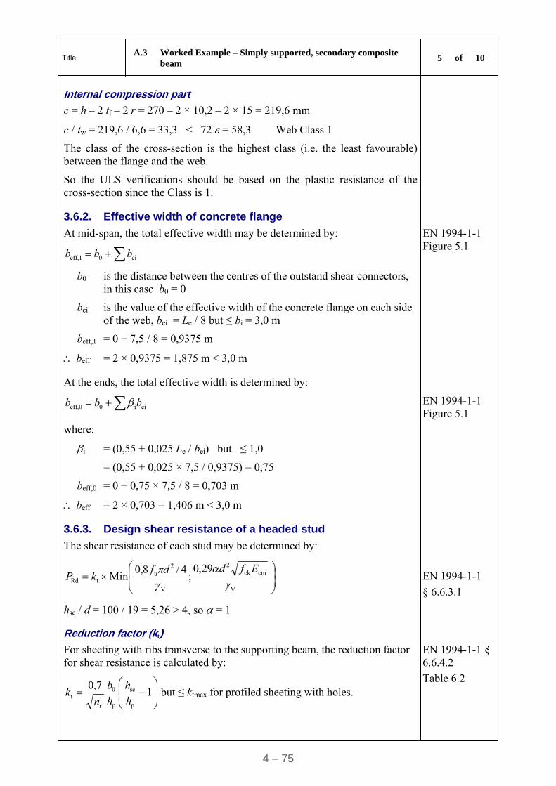
Title A.3 Worked Example – Simply supported, secondary composite
beam 5 of 10
4 – 75
Internal compression part
c = h – 2 tf – 2 r = 270 – 2 × 10,2 – 2 × 15 = 219,6 mm
c / tw = 219,6 / 6,6 = 33,3 < 72 = 58,3 Web Class 1
The class of the cross-section is the highest class (i.e. the least favourable) between the flange and the web.
So the ULS verifications should be based on the plastic resistance of the cross-section since the Class is 1.
3.6.2. Effective width of concrete flange
At mid-span, the total effective width may be determined by:
ei0eff,1 bbb
b0 is the distance between the centres of the outstand shear connectors, in this case b0 = 0
bei is the value of the effective width of the concrete flange on each side of the web, bei = Le / 8 but ≤ bi = 3,0 m
beff,1 = 0 + 7,5 / 8 = 0,9375 m
beff = 2 × 0,9375 = 1,875 m < 3,0 m
EN 1994-1-1 Figure 5.1
At the ends, the total effective width is determined by:
eii0eff,0 bbb EN 1994-1-1 Figure 5.1
where:
i = (0,55 + 0,025 Le / bei) but ≤ 1,0
= (0,55 + 0,025 × 7,5 / 0,9375) = 0,75
beff,0 = 0 + 0,75 × 7,5 / 8 = 0,703 m
beff = 2 × 0,703 = 1,406 m < 3,0 m
3.6.3. Design shear resistance of a headed stud
The shear resistance of each stud may be determined by:
V
cmck2
V
2u
tRd
29,0;
4/8,0Min
Efddf
kP
hsc / d = 100 / 19 = 5,26 > 4, so = 1
EN 1994-1-1
§ 6.6.3.1
Reduction factor (kt)
For sheeting with ribs transverse to the supporting beam, the reduction factor for shear resistance is calculated by:
1
7,0
p
sc
p
0
r
t h
h
h
b
nk but ≤ ktmax for profiled sheeting with holes.
EN 1994-1-1 § 6.6.4.2
Table 6.2
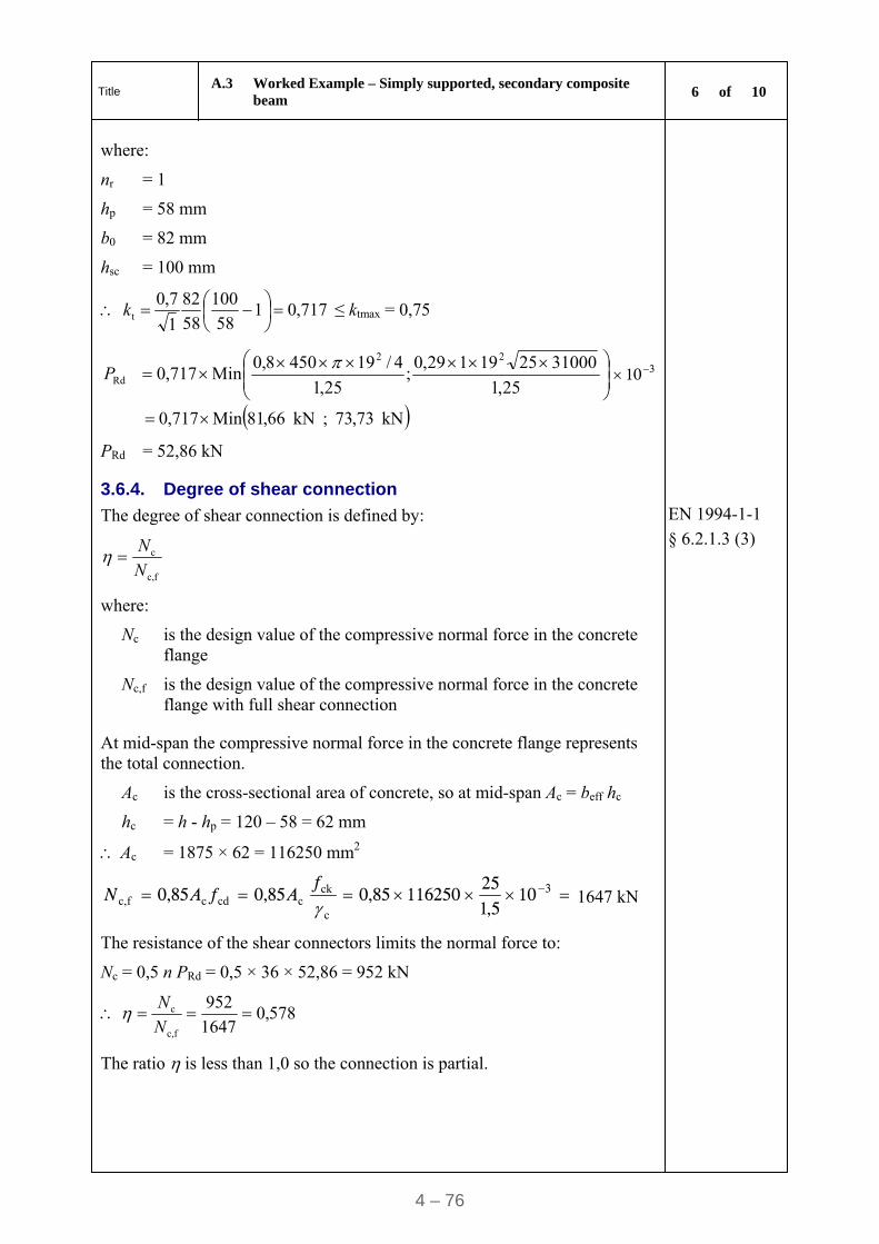
Title A.3 Worked Example – Simply supported, secondary composite
beam 6 of 10
4 – 76
where:
nr = 1
hp = 58 mm
b0 = 82 mm
hsc = 100 mm
717,0158
100
58
82
1
7,0t
k ≤ ktmax = 0,75
25,1
31000 2519 1 29,0;
25,1
4/19 450 8,0Min717,0
22
Rd
P 310
kN73,73;kN66,81Min717,0
PRd = 52,86 kN
3.6.4. Degree of shear connection
The degree of shear connection is defined by:
fc,
c
N
N
EN 1994-1-1
§ 6.2.1.3 (3)
where:
Nc is the design value of the compressive normal force in the concrete flange
Nc,f is the design value of the compressive normal force in the concrete flange with full shear connection
At mid-span the compressive normal force in the concrete flange represents the total connection.
Ac is the cross-sectional area of concrete, so at mid-span Ac = beff hc
hc = h - hp = 120 – 58 = 62 mm
Ac = 1875 × 62 = 116250 mm2
3105,1
25116250 85,085,085,0
c
ckccdcfc, f
AfAN 1647 kN
The resistance of the shear connectors limits the normal force to:
Nc = 0,5 n PRd = 0,5 × 36 × 52,86 = 952 kN
578,01647
952
fc,
c N
N
The ratio is less than 1,0 so the connection is partial.
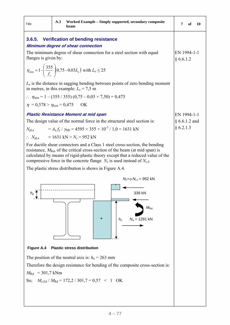
Title A.3 Worked Example – Simply supported, secondary composite
beam 7 of 10
4 – 77
3.6.5. Verification of bending resistance
Minimum degree of shear connection
The minimum degree of shear connection for a steel section with equal flanges is given by:
ey
min 030750355
-1 L,-,f
with Le ≤ 25
Le is the distance in sagging bending between points of zero bending moment in metres, in this example: Le = 7,5 m
min = 1 – (355 / 355) (0,75 – 0,03 × 7,50) = 0,475
= 0,578 > min = 0,475 OK
EN 1994-1-1
§ 6.6.1.2
Plastic Resistance Moment at mid span
The design value of the normal force in the structural steel section is:
Npl,a = Aa fy / M0 = 4595 × 355 × 10-3 / 1,0 = 1631 kN
EN 1994-1-1
§ 6.6.1.2 and
§ 6.2.1.3
Npl,a = 1631 kN > Nc = 952 kN
For ductile shear connectors and a Class 1 steel cross-section, the bending resistance, MRd, of the critical cross-section of the beam (at mid span) is calculated by means of rigid-plastic theory except that a reduced value of the compressive force in the concrete flange Nc is used instead of Nc,f.
The plastic stress distribution is shows in Figure A.4.
MRd
+
-Nc=Nc,f = 952 kN
Na = 1291 kN hn
hp 339 kN
Figure A.4 Plastic stress distribution
The position of the neutral axis is: hn = 263 mm
Therefore the design resistance for bending of the composite cross-section is:
MRd = 301,7 kNm
So, My,Ed / MRd = 172,2 / 301,7 = 0,57 < 1 OK
Title A.3 Worked Example – Simply supported, secondary composite
beam 8 of 10
4 – 78
3.6.6. Shear Resistance
The shear plastic resistance depends on the shear area of the steel beam, which is given by:
Av = A – 2 b tf + (tw + 2 r) tf
EN 1993-1-1
§ 6.2.6 (3)
Av = 4595 – 2 × 135 × 10,2 + (6,6 + 2 × 15) × 10,2 = 2214 mm2
Shear plastic resistance
kN8453 10 01
)3 / 355(2214
)3 / ( 3
M0
yvRdpl, ,
,
fAV -
EN 1994-1-1
§ 6.2.2.2
VEd / Vpl,Rd = 91,80 / 453,8 = 0,202 < 1,0 OK
Verification to shear buckling is not required when:
hw / tw ≤ 72 /
may be conservatively taken as 1,0
hw / tw = (270 – 2 × 10,2) / 6,6 = 37,8 < 72 × 0,81 / 1,0 = 58,3 OK
EN 1993-1-1
§ 6.2.6 (6)
3.6.7. Longitudinal Shear Resistance of the Slab
The plastic longitudinal shear stresses is given by :
xh
Fv
f
dEd
EN 1992-1-1
§ 6.2.4
Figure 6.7
where:
x = 7,5 / 2 = 3,75 m
The value of x is half the distance between the section where the moment is zero and the section where the moment is a maximum, so there are two areas for the longitudinal shear resistance of the slab.
Fd = Nc / 2 = 951,56 / 2 = 475,8 kN
hf = h - hp = 120 – 58 = 62 mm
375062
108,475 3
f
dEd
xh
Fv
2,05 N/mm2
To prevent crushing of the compression struts in the concrete flange, the following condition should be satisfied:
ffcdEd cossin fv with 250/16,0 ckf and f = 45°
5,45,05,1
25
250
2516,0Ed
v N/mm2 OK
The following inequality should be satisfied for the transverse reinforcement:
Asf fyd / sf ≥ vEd hf / cot θf where fyd = 500 / 1,15 = 435 N/mm2
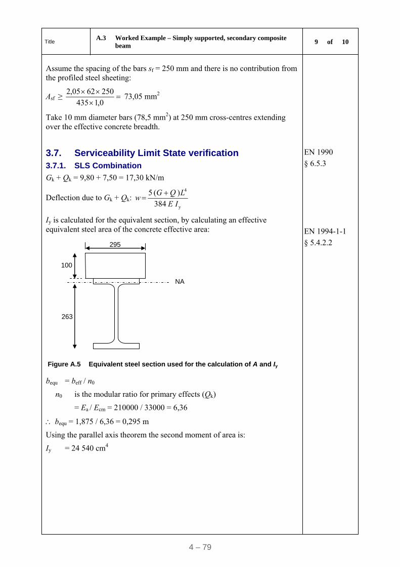
Title A.3 Worked Example – Simply supported, secondary composite
beam 9 of 10
4 – 79
Assume the spacing of the bars sf = 250 mm and there is no contribution from the profiled steel sheeting:
Asf ≥ 0,1435
2506205,2 73,05 mm2
Take 10 mm diameter bars (78,5 mm2) at 250 mm cross-centres extending over the effective concrete breadth.
3.7. Serviceability Limit State verification 3.7.1. SLS Combination
EN 1990
§ 6.5.3
Gk + Qk = 9,80 + 7,50 = 17,30 kN/m
Deflection due to Gk + Qk: 384
) ( 5
y
4
IE
LQGw
Iy is calculated for the equivalent section, by calculating an effective equivalent steel area of the concrete effective area:
100
NA
263
295
Figure A.5 Equivalent steel section used for the calculation of A and Iy
EN 1994-1-1
§ 5.4.2.2
bequ = beff / n0
n0 is the modular ratio for primary effects (Qk)
= Ea / Ecm = 210000 / 33000 = 6,36
bequ = 1,875 / 6,36 = 0,295 m
Using the parallel axis theorem the second moment of area is:
Iy = 24 540 cm4
Title A.3 Worked Example – Simply supported, secondary composite
beam 10 of 10
4 – 80
For the permanent action:
n = 2Ea / Ecm = 19,08 for permanent loads (Gk)
bequ = 1,875 / 19,06 = 0,0984 m
The second moment of area is calculated as:
Iy = 18 900 cm4
The deflection can be obtained by combining the second moment of area for the variable and the permanent actions as follows:
1024540
507
1018900
809
210000384
575
88
4
,,
, w 16 mm
EN 1994-1-1
§ 5.4.2.2(11)
The deflection under (Gk + Qk) is L/469 EN 1994-1-1 § 7.3.1
Note 1: The deflection limits should be specified by the client and the National Annex may specify some limits.
Note 2: The National Annex may specify limits concerning the frequency of vibration.
EN 1994-1-1
§ 7.3.2
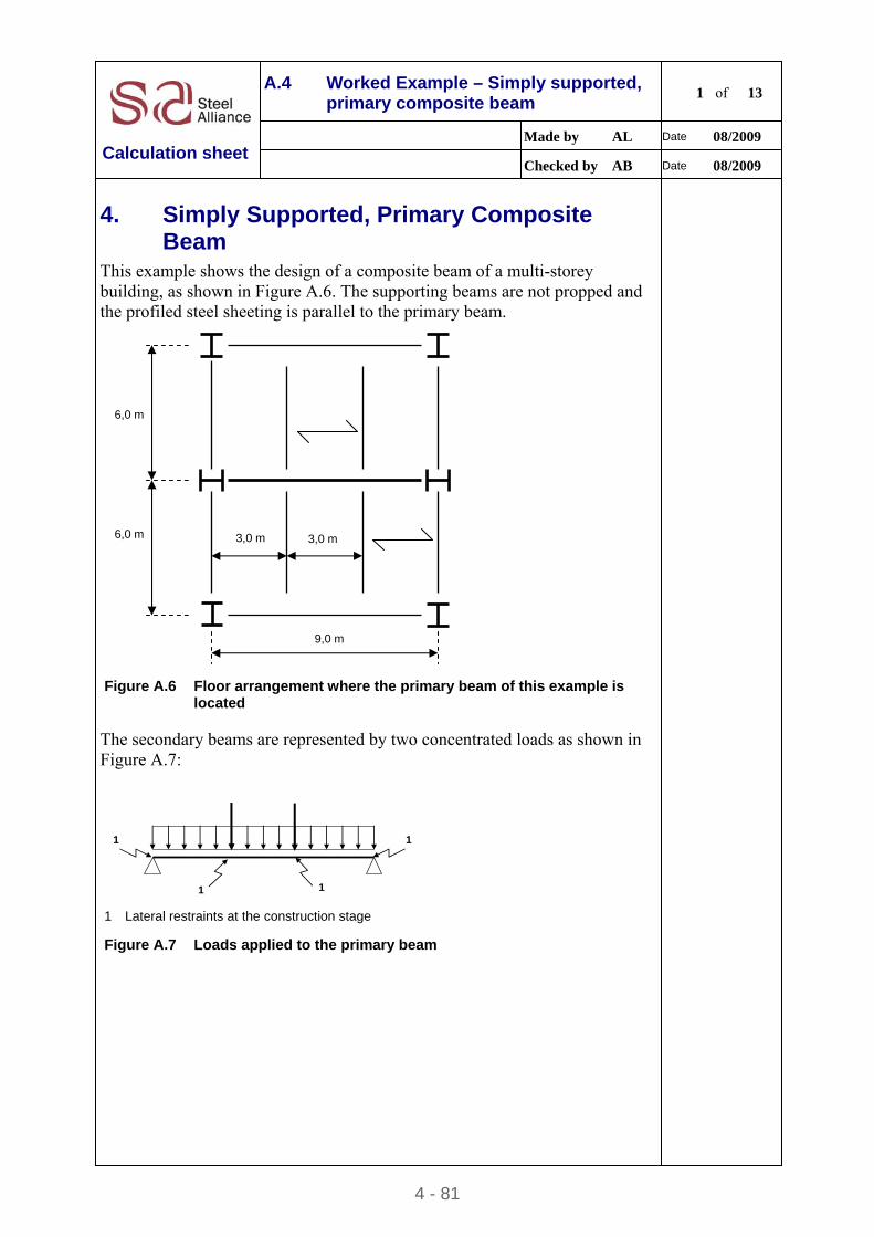
4 - 81
A.4 Worked Example – Simply supported, primary composite beam
1 of 13
Made by AL Date 08/2009
Calculation sheet Checked by AB Date 08/2009
4. Simply Supported, Primary Composite Beam
This example shows the design of a composite beam of a multi-storey building, as shown in Figure A.6. The supporting beams are not propped and the profiled steel sheeting is parallel to the primary beam.
6,0 m
6,0 m
9,0 m
3,0 m 3,0 m
Figure A.6 Floor arrangement where the primary beam of this example is
located
The secondary beams are represented by two concentrated loads as shown in Figure A.7:
1 1
1 1 1 Lateral restraints at the construction stage
Figure A.7 Loads applied to the primary beam
Title A.4 Worked Example – Simply supported, primary composite beam 2 of 13
4 – 82
The beam is an I-rolled profile in bending about the major axis. This example includes:
the classification of the cross-section
the calculation of the effective width of the concrete flange
the calculation of the shear resistance of a headed stud
the calculation of the degree of shear connection
the calculation of the bending resistance
the calculation of the shear resistance
the calculation of the longitudinal shear resistance of the slab
the calculation of the deflection at serviceability limit state.
This example does not include any shear buckling verification of the web.
4.1. Partial factors G = 1,35 (permanent loads)
Q = 1,50 (variable loads)
M0 = 1,0
M1 = 1,0
V = 1,25
C = 1,5
EN 1990
EN 1993-1-1,
§ 6.1 (1)
EN 1994-1-1,
§ 6.6.3.1
EN 1992-1-1
4.2. Basic data
Span length : 9,00 m
Bay width : 6,00 m
Slab depth : 14 cm
Partitions : 0,75 kN/m2
Secondary beams (IPE 270) : 0,354 kN/m
Imposed load : 2,50 kN/m2
Construction load : 0,75 kN/m2
Reinforced concrete density : 25 kN/m3
4.3. Choose section
Try IPE 400 – Steel grade S355
Title A.4 Worked Example – Simply supported, primary composite beam 3 of 13
4 – 83
4.3.1. Geometric data
Depth ha = 400 mm
Width b = 180 mm
Web thickness tw = 8,6 mm
Flange thickness tf = 13,5 mm
Root radius r = 21 mm
Mass 66,3 kg/m
Section area Aa = 84,46 cm2
z
z
y y
tf
tw
b
ha
Second moment of area about the major axis Iy = 23130 cm4
Elastic section modulus about the major axis Wel,y = 1156 cm3
Plastic section modulus about the major axis Wpl,y = 1307 cm3
Radius of gyration about the minor axis iz = 3,95 cm
Modulus of elasticity of steel Ea = 210 000 N/mm2
Yield strength
Steel grade S355
The maximum thickness is 13,5 mm < 40 mm, so: fy = 355 N/mm2
EN 1993-1-1,
Table 3.1
Note: The National Annex may impose either the values of fy from Table 3.1 or the values from the product standard.
Profiled steel sheeting
Thickness of sheet t = 0,75 mm
Slab depth h = 140 mm
Overall depth of the profiled steel
sheeting excluding embossments hp = 58 mm
Trapezoidal ribs b1 = 62 mm
b2 = 101 mm
e = 207 mm
Connectors
Diameter d = 19 mm
Overall nominal height hsc = 100 mm
Ultimate tensile strength fu = 450 N/mm2
Number of studs n = 74 per row
(Stud at beam mid-span ignored)
Title A.4 Worked Example – Simply supported, primary composite beam 4 of 13
4 – 84
0,5hp
hp
hsc
h
b0
b1 b2
e
Figure A.8 Geometry of the composite beam
Concrete class: C 25/30
Value of the compressive strength at 28 days fck = 25 N/mm2
Secant modulus of elasticity of concrete Ecm = 31 000 N/mm2
EN 1992-1-1,
§ 3.1.3
Table 3.1
4.3.2. Actions on the beam at ULS
Permanent load:
To take into account the troughs of the profiled steel sheeting , the weight of the slab for the secondary beams is taken as:
207,0
058,0
2
145,0106,014,00,325 = 7,86 kN/m
Concentrated loads during the construction stage:
FG = (0,354 + 7,86) × 6,0 = 49,28 kN
Permanent loads in the final stage:
FG = (0,354 + 7,86 + 0,75 × 3,0) × 6,0 = 62,78 kN
Self weight of the primary beam:
qG = 9,81 × 66,3 × 10-3 = 0,65 kN/m
Variable load (Imposed load):
Concentrated loads during the construction stage:
FQ = 0,75 × 3,0 × 6,0 = 13,5 kN
Concentrated loads in the final stage:
FQ = 2,5 × 3,0 × 6,0 = 45,0 kN
Title A.4 Worked Example – Simply supported, primary composite beam 5 of 13
4 – 85
ULS Combination:
G FG + Q FQ = 1,35 × 62,78 + 1,50 ×45,0 = 152,25 kN
G qG + Q qQ = 1,35 × 0,65 = 0,877 kN/m
Eq. (6.10) is used. In some countries, the National Annex may specify the use of equations (6.10a) and (6.10b).
EN 1990
§ 6.4.3.2
ULS Combination during the construction stage:
G FG + Q FQ = 1,35 × 49,28 + 1,50 ×13,5 = 86,78 kN
G qG + Q qQ = 1,35 × 0,65 = 0,877 kN/m
Bending moment diagram
M
456,6 kNm Figure A.9 Bending moment diagram at ULS in the final stage
Maximum moment at mid span:
My,Ed = 3,0 × 152,25 + 0,125 × 0,877 × 9,02 = 465,6 kNm
Maximum moment at mid span (sequence of construction):
My,Ed = 3,0 × 86,78 + 0,125 × 0,877 × 9,02 = 269,2 kNm
Shear force diagram
V
156,20 kN
Figure A.10 Shear force diagram at ULS in the final stage
Maximum shear force at supports:
VEd = 152,25 + 0,5 × 0,877 × 9,0 = 156,20 kN
Maximum shear force at supports (sequence of construction):
VEd = 86,78 + 0,5 × 0,877 × 9,0 = 90,73 kN
4.3.3. Section classification:
The parameter is derived from the yield strength: 0,81 355235235
y
f
Note: The classification is made for the non composite beam. For the composite beam the classification is more favourable for the web.
Title A.4 Worked Example – Simply supported, primary composite beam 6 of 13
4 – 86
Outstand flange : flange under uniform compression
c = (b – tw – 2 r) / 2 = (180 – 8,6 – 2 × 21)/2 = 64,7 mm
c/tf = 64,7 / 13,5 = 4,79 ≤ 9 = 7,29 Flange Class 1
EN 1993-1-1
Table 5.2
(sheet 2 of 3)
Internal compression part
c = ha – 2 tf – 2 r = 400 – 2 × 13,5 – 2 × 21 = 331 mm
c / tw = 331 / 8,6 = 38,5 < 72 = 58,3 Web Class 1
EN 1993-1-1
Table 5.2
(sheet 1 of 3)
The class of the cross-section is the highest class (i.e. the least favourable) of the flange and the web.
In this case the overall section is Class 1.
For Class 1 sections, the ULS verifications should be based on the plastic resistance of the cross-section.
4.3.4. Construction stage
Cross-sectional moment resistance
The design bending resistance of a cross-section is given by:
Mc,Rd = Mpl,Rd = Wpl,y fy / M0 = (1307 × 355 / 1,0) / 1000
EN 1993-1-1
§ 6.2.5
Mc,Rd = 463,98 kNm
My,Ed / Mc,Rd = 269,2 / 463,98 = 0,58 < 1 OK
Reduction factor for lateral–torsional buckling
To determine the design buckling resistance of a laterally unrestrained beam, the reduction factor for lateral–torsional buckling must be determined. The restraint provided by the steel sheet is in this case quite small and it is neglected. The following calculation determines this factor by a simplified method for lateral–torsional buckling. This method avoids calculating the elastic critical moment.
Non-dimensional slenderness
The non-dimensional slenderness may be obtained from the simplified method for steel grade S355:
0,853 89
300/3,95
89
/ z
LT iL
SN002[4]
For rolled profiles, 0,4 LT,0
Note: The value of LT,0 may be given in the National Annex. The recommended value is 0,4.
So LT,0LT 0,853 = 0,4
EN 1993-1-1,
§ 6.3.2.3(1)
Title A.4 Worked Example – Simply supported, primary composite beam 7 of 13
4 – 87
Reduction factor
For rolled sections, the reduction factor for lateral–torsional buckling is calculated from:
EN 1993-1-1
§ 6.3.2.3 (1)
2LT
LT
LT
2LT
2LTLT
LT1
1.0 but
1
where : 1 0,5 LTLT,0LTLTLT
2
LT is the imperfection factor for LTB. When applying the method for rolled profiles, the LTB curve has to be selected from Table 6.5:
For ha/b = 400 / 180 = 2,22 > 2 Curve ‘c’ (LT = 0,49)
EN 1993-1-1
Table 6.5
Table 6.3
0,4 LT,0 and = 0,75
Note: The values of LT,0 and may be given in the National Annex. The recommended values are 0,4 and 0,75 respectively.
We obtain : 0,884 (0,853)0,75 0,40,853 0,49 1 0,5 2LT
and : 0,730 (0,853)0,75(0,884) 0,884
1
22LT
Then, we verify : LT = 0,730 < 1,0
but : LT = 0,730 < 2LT / 1 = 1,374
So : LT = 0,730
Design buckling resistance moment
Mb,Rd = LT Wpl,y fy / M1
Mb,Rd = (0,730 × 1307000 × 355 / 1,0) × 10-6 = 338,7 kNm
My,Ed / Mb,Rd = 269,2 / 338,7 = 0,795 < 1,0 OK
EN 1993-1-1
§ 6.3.2.1
Shear Resistance
The shear plastic resistance depends on the shear area, which is given by:
Av = A – 2 b tf + (tw + 2 r) tf
Av = 8446 – 2 × 180 × 13,5 + (8,6 + 2 × 21) × 13,5 = 4269 mm2
EN 1993-1-1
§ 6.2.6 (3)
Shear plastic resistance
kN 874,97 1,0
10)3 / (3554269
)3 / (
3
M0
yvRdpl,
fA
V
EN 1993-1-1
§ 6.2.6 (2)
VEd/Vpl,Rd = 90,73 / 874,97 = 0,104 < 1,0 OK
Title A.4 Worked Example – Simply supported, primary composite beam 8 of 13
4 – 88
Note that the verification to shear buckling is not required when :
hw / tw ≤ 72 /
The relevant value of is : = 1,2
hw / tw = (400 – 2 × 13,5) / 8,6 = 43 < 72 × 0,81 / 1,2 = 48,6
EN 1993-1-1
§ 6.2.6 (6)
EN 1993-1-5
§ 5.1 (2) Interaction between bending moment and shear force
If VEd < Vpl,Rd / 2 then the shear force may be neglected.
So, VEd = 90,73 kN < Vpl,Rd / 2 = 874,97 / 2 = 437,50 kN OK
EN 1993-1-1
§ 6.2.8 (2)
4.3.5. Final stage
Effective width of concrete flange
The effective width is constant between 0,25 L and 0,75 L, where L is the span length. From L/4 to the closest support, the effective width decreases linearly. The concentrated loads are located between 0,25 L and 0,75 L.
EN 1994-1-1
§ 5.4.1.2
The total effective width is determined by: (Figure 5.1)
∑eff,1 ei0 bb b
b0 is the distance between the centres of the outstand shear connectors, in this case b0 = 0
bei is the value of the effective width of the concrete flange on each side of the web and taken as bei = Le / 8 but ≤ bi = 3,0 m
beff,1 = 0 + 9,0 / 8 = 1,125 m, then beff = 2 × 1,125 = 2,25 m < 3,0 m
Design shear resistance of a headed stud
The shear resistance should be determined by:
V
cm
V
ulRd Min
Efddf
kP ck 29,0;
4/ 8,0 22
EN 1994-1-1
§ 6.6.3.1
hsc / d = 100 / 19 = 5,26 > 4, so = 1
Reduction factor (kl)
For sheeting with ribs transverse to the supporting beam, the reduction factor for shear resistance is calculated by:
EN 1994-1-1
§ 6.6.4.1
16,0
p
sc
p
0l
h
h
h
bk but ≤ 1
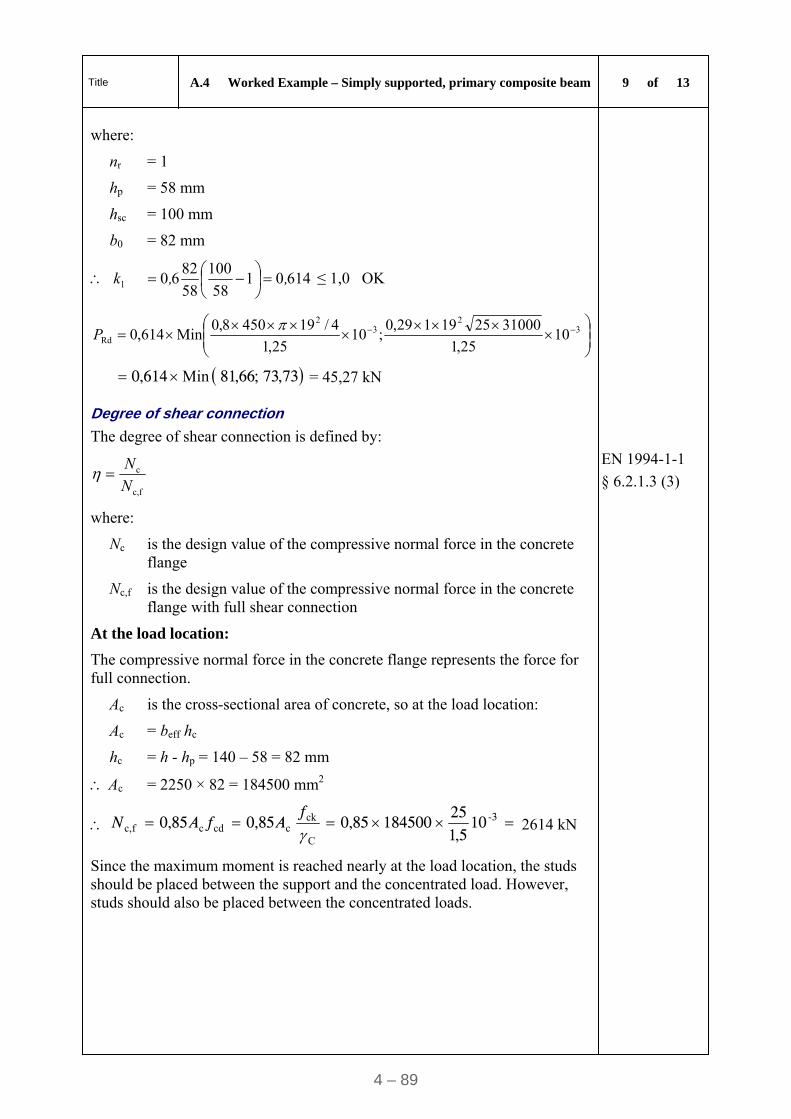
Title A.4 Worked Example – Simply supported, primary composite beam 9 of 13
4 – 89
where:
nr = 1
hp = 58 mm
hsc = 100 mm
b0 = 82 mm
6140158
100
58
8260l ,,k
≤ 1,0 OK
3
23
2
Rd 1025,1
31000 2519 1 29,0;10
25,1
4/19 450 8,0Min614,0
P
73,73;66,81614,0 Min = 45,27 kN
Degree of shear connection
The degree of shear connection is defined by:
fc,
c
N
N
where:
Nc is the design value of the compressive normal force in the concrete flange
EN 1994-1-1
§ 6.2.1.3 (3)
Nc,f is the design value of the compressive normal force in the concrete flange with full shear connection
At the load location:
The compressive normal force in the concrete flange represents the force for full connection.
Ac is the cross-sectional area of concrete, so at the load location:
Ac = beff hc
hc = h - hp = 140 – 58 = 82 mm
Ac = 2250 × 82 = 184500 mm2
3105,1
25184500 85,085,085,0 -
C
ckccdcfc, f
AfAN 2614 kN
Since the maximum moment is reached nearly at the load location, the studs should be placed between the support and the concentrated load. However, studs should also be placed between the concentrated loads.
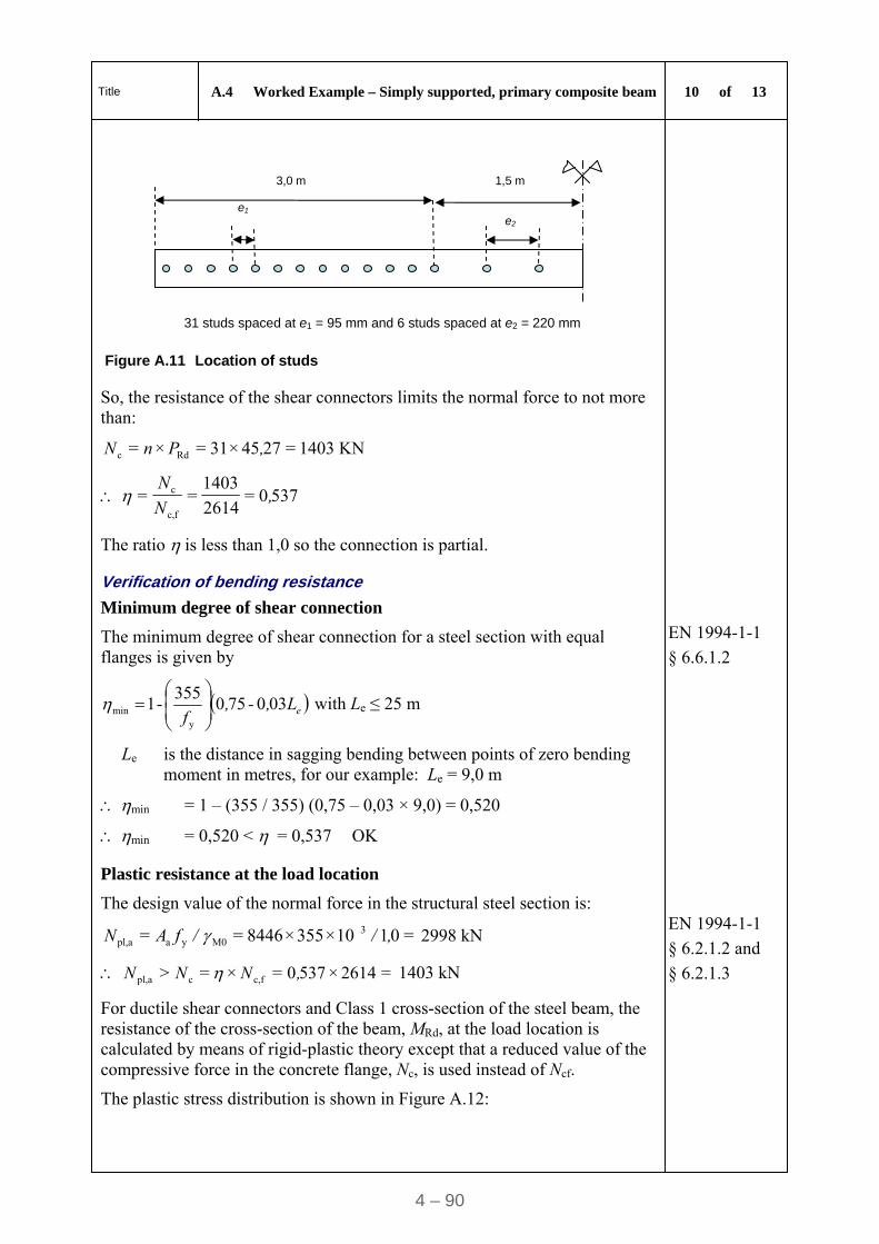
Title A.4 Worked Example – Simply supported, primary composite beam 10 of 13
4 – 90
e2
e1
3,0 m 1,5 m
31 studs spaced at e1 = 95 mm and 6 studs spaced at e2 = 220 mm
Figure A.11 Location of studs
So, the resistance of the shear connectors limits the normal force to not more than:
=2745×31=×= Rdc ,PnN 1403 KN
5370=2614
1403==
fc,
c ,N
N
The ratio is less than 1,0 so the connection is partial.
Verification of bending resistance
Minimum degree of shear connection
The minimum degree of shear connection for a steel section with equal flanges is given by
EN 1994-1-1
§ 6.6.1.2
eL,-,f
030750355
-1 y
min
with Le ≤ 25 m
Le is the distance in sagging bending between points of zero bending moment in metres, for our example: Le = 9,0 m
min = 1 – (355 / 355) (0,75 – 0,03 × 9,0) = 0,520
min = 0,520 < = 0,537 OK
Plastic resistance at the load location
The design value of the normal force in the structural steel section is:
=0110×355×8446== 3M0yaapl, ,/ /fAN 2998 kN
=2614×5370=×=> fc,capl, ,NNN 1403 kN
EN 1994-1-1
§ 6.2.1.2 and
§ 6.2.1.3
For ductile shear connectors and Class 1 cross-section of the steel beam, the resistance of the cross-section of the beam, MRd, at the load location is calculated by means of rigid-plastic theory except that a reduced value of the compressive force in the concrete flange, Nc, is used instead of Ncf.
The plastic stress distribution is shown in Figure A.12:
Title A.4 Worked Example – Simply supported, primary composite beam 11 of 13
4 – 91
MRd
+
- Nc=Nc,f= 1403 kN
Na= 2201 kN hn
hp 797 kN
Figure A.12 Plastic stress distribution on the beam
The position of the plastic neutral axis is: hn = 388 mm
Therefore, the design bending resistance of the composite cross-section is:
MRd = 738 kNm
My,Ed / MRd = 465,6 / 738 = 0,63 < 1,0 OK
Shear Resistance
The plastic shear resistance is the same as for steel beam alone.
97874 Rdpl, ,V kN
EN 1994-1-1
§ 6.2.2.2
VEd / Vpl,Rd = 156,20 / 874,97 = 0,18 < 1,0 OK
Interaction between bending moment and shear force
If VEd < Vpl,Rd / 2 then the shear force may be neglected.
So, VEd = 156,20 kN < Vpl,Rd / 2 = 874,97 / 2 = 437,50 kN OK
EN 1993-1-1
§ 6.2.8 (2)
Longitudinal Shear Resistance of the Slab
The plastic longitudinal shear stresses is given by :
xh
Fv
f
dEd
EN 1992-1-1
§ 6.2.4
(Figure 6.7)
where x = 9,0 / 3 = 3,0 m
The value for x is the distance between the restraint and the point load. Therefore there are three areas for the longitudinal shear resistance.
Fd = Nc / 2 = 1403 / 2 = 701,5 kN
hf = h - hp = 140 – 58 = 82 mm
300082
105,701 3
Ed xh
F
f
dv 2,85 N/mm2
Title A.4 Worked Example – Simply supported, primary composite beam 12 of 13
4 – 92
To prevent crushing of the compression struts in the concrete flange, the following condition should be satisfied:
ffcdEd cossin fv with 250/16,0 ckf and f = 45°
5,45,05,1
25
250
2516,0Ed
v N/mm2 OK
The following inequality should be satisfied for the transverse reinforcement :
Asf fyd / sf ≥ vEd hf / cot θf where fyd = 500 / 1,15 = 435 N/mm2
Assume the spacing of the bars sf = 200 mm and there is no contribution from the profiled steel sheeting
Asf ≥ 0,1435
2008285,2107,4 mm2
Take 12 mm diameter bars (113 mm2) at 200 mm spacing.
4.4. Serviceability Limit State verifications
The deflection due to G + Q is calculated as:
GG
G4
FIE
Law
FIE
La
IE
Lqw
y
22
y
22
y
4
24)4(3
24)(3
384
5
a
a
And the total deflection is: w = wG + wQ
4.4.1. Construction stage
SLS Combination during the construction stage
FG + FQ = 49,28 + 13,5 = 62,78 kN
EN 1990
§ 6.5.3
qG = 0,65 kN/m
Deflection during the construction stage
Iy is the second moment of area of the steel beam.
492801023130210000 24
)3000490003(3000
1023130210000 384
900065,0 5
4
22
4
4
-
Gw
mm 3,272,261,1 Gw
mm2,7135001023130 210000 24
)30004-90003(30004
22
Q
w
w = wG + wQ = 27,3 + 7,2 = 34,5 mm
The deflection under (G + Q) is L/261
Title A.4 Worked Example – Simply supported, primary composite beam 13 of 13
4 – 93
Deflection in the final stage
FG + FQ = 62,78 + 45,0 = 107,78 kN
qG = 0,65 kN/m
EN 1990
§ 6.5.3
Deflection at the final stage:
Iy is calculated for the equivalent section, by calculating an effective equivalent steel area of the concrete effective area.
bequ = beff / n0
n0 is the modular ratio for primary effects (Qk)
= Ea / Ecm = 210000 / 31000 = 6,77
beq = 2,25 / 6,77 = 0,332 m
Using the parallel axis theorem the second moment of area is obtained:
Iy = 82458 cm4
EN 1994-1-1
§ 5.4.2.2
For the permanent action:
n = 2Ea / Ecm = 20,31 for permanent loads (Gk)
bequ = 2,25 / 20,31 = 0,111 m
The second moment of area is calculated as:
Iy = 62919 cm4
EN 1994-1-1
§ 5.4.2.2(11)
The deflection can be obtained by combining the second moment of area for the variable and the permanent actions as follows:
wG = 27,3 mm
mm6,2135001062919210000 24
)30004-90003(30004
22
partitions
w
450001082458210000 24
)30004-90003(30004
22
Q
w = 6,7 mm
So, w = wG + wpartitions + wQ = 27,3 + 2,6 + 6,7 = 36,6 mm
The deflection under (G + Q) is L/246 EN 1994-1-1 § 7.3.1
Note 1: The deflection limits should be specified by the client and the National Annex may specify some limits.
Note 2: The National Annex may specify frequency limits. EN 1993-1-1
§ 7.2.3
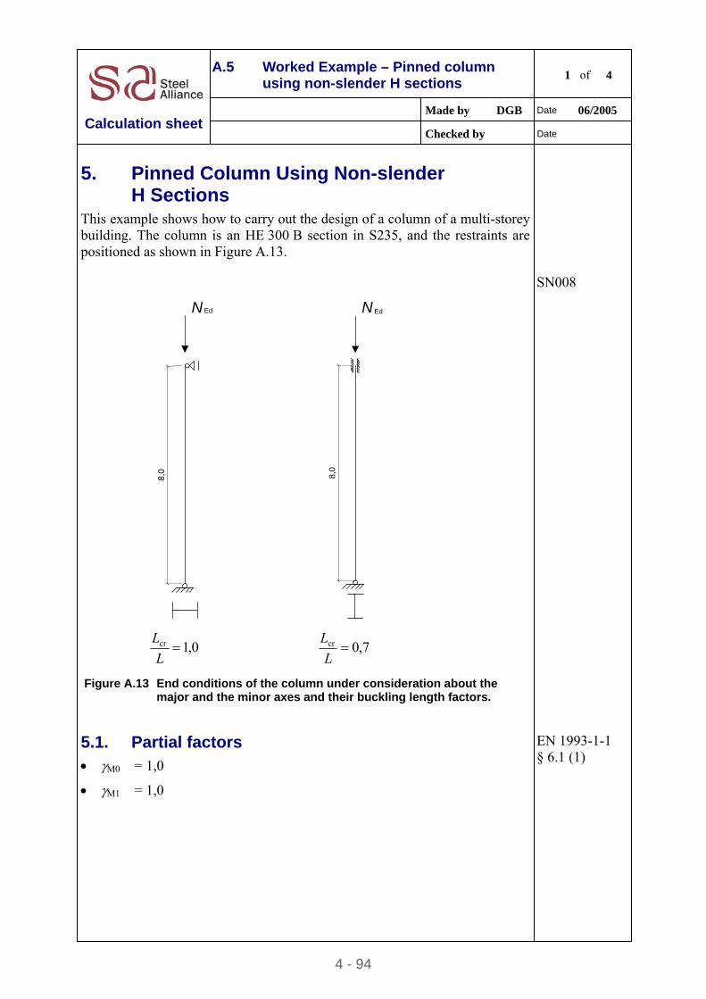
4 - 94
A.5 Worked Example – Pinned column using non-slender H sections
1 of 4
Made by DGB Date 06/2005
Calculation sheet Checked by Date
5. Pinned Column Using Non-slender H Sections
This example shows how to carry out the design of a column of a multi-storey building. The column is an HE 300 B section in S235, and the restraints are positioned as shown in Figure A.13.
Ed
8,0
N
Ed
8,0
N
0,1cr L
L 7,0cr
L
L
Figure A.13 End conditions of the column under consideration about the
major and the minor axes and their buckling length factors.
SN008
5.1. Partial factors M0 = 1,0
M1 = 1,0
EN 1993-1-1 § 6.1 (1)
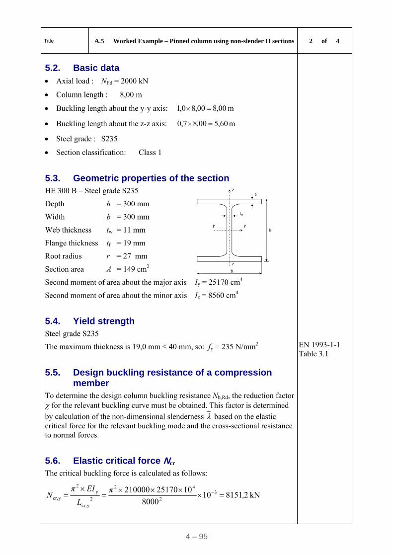
Title A.5 Worked Example – Pinned column using non-slender H sections 2 of 4
4 – 95
5.2. Basic data
Axial load : NEd = 2000 kN
Column length : 8,00 m
Buckling length about the y-y axis: 00,800,80,1 m
Buckling length about the z-z axis: 60,500,87,0 m
Steel grade : S235
Section classification: Class 1
5.3. Geometric properties of the section
HE 300 B – Steel grade S235
Depth h = 300 mm
Width b = 300 mm
Web thickness tw = 11 mm
Flange thickness tf = 19 mm
Root radius r = 27 mm
Section area A = 149 cm2
z
z
y y
tf
tw
b
h
Second moment of area about the major axis Iy = 25170 cm4
Second moment of area about the minor axis Iz = 8560 cm4
5.4. Yield strength
Steel grade S235
The maximum thickness is 19,0 mm < 40 mm, so: fy = 235 N/mm2
EN 1993-1-1 Table 3.1
5.5. Design buckling resistance of a compression member
To determine the design column buckling resistance Nb,Rd, the reduction factor for the relevant buckling curve must be obtained. This factor is determined
by calculation of the non-dimensional slenderness λ based on the elastic critical force for the relevant buckling mode and the cross-sectional resistance to normal forces.
5.6. Elastic critical force Ncr
The critical buckling force is calculated as follows:
kN 28151108000
1025170210000 32
42
2ycr,
y2
ycr, ,π
L
EIπN
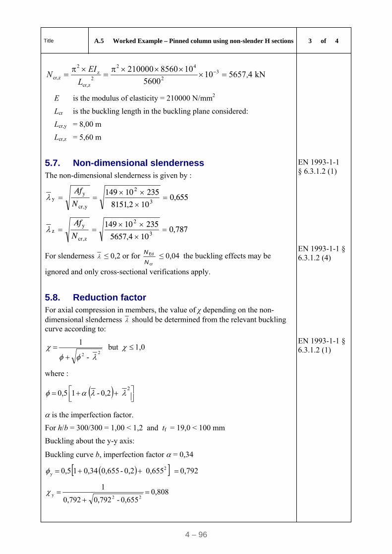
Title A.5 Worked Example – Pinned column using non-slender H sections 3 of 4
4 – 96
kN45657105600
108560210000 32
42
2zcr,
z2
zcr, ,L
EIN
E is the modulus of elasticity = 210000 N/mm2
Lcr is the buckling length in the buckling plane considered:
Lcr,y = 8,00 m
Lcr,z = 5,60 m
5.7. Non-dimensional slenderness The non-dimensional slenderness is given by :
655,0102,8151
235101493
2
ycr,
yy
N
Af
787,0104,5657
235101493
2
zcr,
yz
N
Af
For slenderness ≤ 0,2 or for cr
Ed
N
N ≤ 0,04 the buckling effects may be
ignored and only cross-sectional verifications apply.
EN 1993-1-1 § 6.3.1.2 (1)
EN 1993-1-1 § 6.3.1.2 (4)
5.8. Reduction factor For axial compression in members, the value of χ depending on the non-dimensional slenderness should be determined from the relevant buckling curve according to:
1,0but -
1
22
where :
2 0,2 - 1 0,5
is the imperfection factor.
EN 1993-1-1 § 6.3.1.2 (1)
For h/b = 300/300 = 1,00 < 1,2 and tf = 19,0 < 100 mm
Buckling about the y-y axis:
Buckling curve b, imperfection factor = 0,34
0,792 0,655 0,2 - 0,655 0,34 1 0,5 2y
0,808 0,655 - 0,792 0,792
1
22y
Title A.5 Worked Example – Pinned column using non-slender H sections 4 of 4
4 – 97
Buckling about the z-z axis:
Buckling curve c, imperfection factor = 0,49
0,953 0,787 0,2 - 0,787 0,49 1 0,5 2z
0,671 0,787 - 0,953 0,953
1
22z
= min (y; z ) = min (0,808; 0,671) = 0,671 < 1,0
(when > 1 then = 1)
5.9. Design buckling resistance of a compression member
5,2349100,1
23510149671,0 3
2
M1
yRdb,
fAN kN
The following expression must be verified:
0,185,05,2349
2000
Rdb,
Ed N
N OK
EN 1993-1-1 § 6.3.1.1 (3)
EN 1993-1-1 § 6.3.1.1 (1)
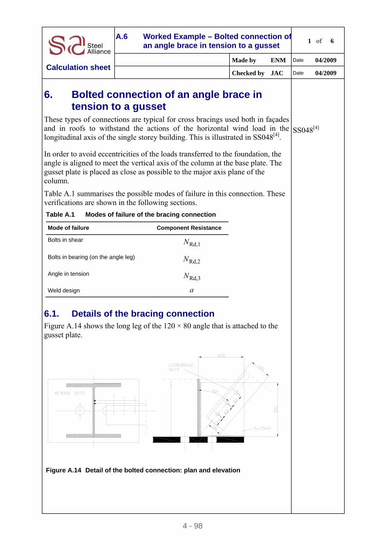
4 - 98
A.6 Worked Example – Bolted connection of an angle brace in tension to a gusset
1 of 6
Made by ENM Date 04/2009
Calculation sheet Checked by JAC Date 04/2009
6. Bolted connection of an angle brace in tension to a gusset
These types of connections are typical for cross bracings used both in façades and in roofs to withstand the actions of the horizontal wind load in the longitudinal axis of the single storey building. This is illustrated in SS048[4].
SS048[4]
In order to avoid eccentricities of the loads transferred to the foundation, the angle is aligned to meet the vertical axis of the column at the base plate. The gusset plate is placed as close as possible to the major axis plane of the column.
Table A.1 summarises the possible modes of failure in this connection. These verifications are shown in the following sections.
Table A.1 Modes of failure of the bracing connection
Mode of failure Component Resistance
Bolts in shear Rd,1N
Bolts in bearing (on the angle leg) Rd,2N
Angle in tension Rd,3N
Weld design a
6.1. Details of the bracing connection
Figure A.14 shows the long leg of the 120 × 80 angle that is attached to the gusset plate.
Figure A.14 Detail of the bolted connection: plan and elevation
Title A.6 Worked Example – Bolted connection of an angle brace in
tension to a gusset plate 2 of 6
4 – 99
Common practice is to minimize the eccentricity between the bracing member and the column axis. The gusset plate is welded to the column web and to the base plate using double fillet welds (see Figure A.14). Although there is some eccentricity in order to avoid the anchor bolt on the axis of the column, this is better than the bracing being on the plane of the column flange.
6.1.1. Main joint data
Configuration Angle to gusset plate welded to a column web
Column HEB 300, S275
Bracing 120 × 80 × 12 angle, S275
Type of connection Bracing connection using angle to gusset plate and non-preloaded bolts
Category A: Bearing type
Gusset plate 250 300 15, S275
Bolts M20, class 8.8
Welds Gusset plate to column web: fillet weld, a = 4 mm (see 6.2.4).
Gusset plate to base plate: fillet weld, a = 4 mm (see 6.2.4).
6.1.2. Column HEB 300, S275
Depth hc = 300 mm
Width bc = 300 mm
Thickness of the web tw,c = 11 mm
Thickness of the flange tf,c = 19 mm
Fillet radius r = 27 mm
Area Ac = 149,1 cm2
Second moment of area Iy = 25170 cm4
Depth between fillets dc = 208 mm
Yield strength fy,c = 275 N/mm2
Ultimate tensile strength fu,c = 430 N/mm2
Title A.6 Worked Example – Bolted connection of an angle brace in
tension to a gusset plate 3 of 6
4 – 100
6.1.3. Angle 120 × 80 × 12, S
Depth hac = 120 mm
Width bac = 80 mm
Thickness of the angle tac = 12 mm
Fillet radius r1 = 11 mm
Fillet radius r2 = 5,5 mm
Area Aac = 22,7 cm2
Second moment of area Iy = 322,8 cm4
Yield strength fy,ac = 275 N/mm2
Ultimate tensile strength fu,ac = 430 N/mm2
6.1.4. Gusset plate 250 300 15, S275
Depth hp = 300 mm
Width bp = 250 mm
Thickness tp = 15 mm
Yield strength fy,p = 275 N/mm2
Ultimate tensile strength fu,p = 430 N/mm2
Direction of load transfer (1)
Number of bolt rows n1 = 3
Angle edge to first bolt row el = 50 mm
Pitch between bolt rows pl = 80 mm
Direction perpendicular to load transfer (2)
Number of lines of bolts n2 = 1
Angle attached leg edge to bolt line e2 = 80 mm
6.1.5. Bolts M20, 8.
Total number of bolts ( 21 nnn ) n = 3
Tensile stress area As = 245 mm2
Diameter of the shank d = 20 mm
Diameter of the holes d0 = 22 mm
Diameter of the washer dw = 37 mm
Yield strength fyb = 640 N/mm2
Ultimate tensile strength fub = 800 N/mm2
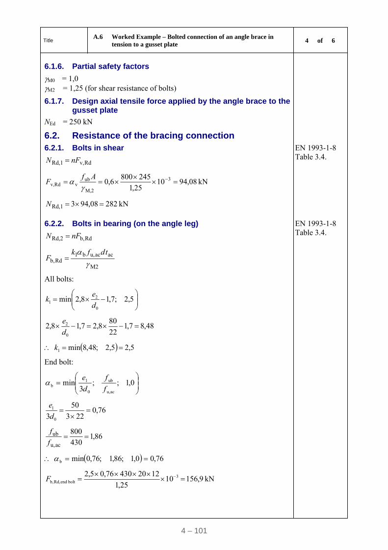
Title A.6 Worked Example – Bolted connection of an angle brace in
tension to a gusset plate 4 of 6
4 – 101
6.1.6. Partial safety factors
M0 = 1,0 M2 = 1,25 (for shear resistance of bolts)
6.1.7. Design axial tensile force applied by the angle brace to the gusset plate
NEd = 250 kN
6.2. Resistance of the bracing connection
6.2.1. Bolts in shear
Rdv,Rd,1 nFN
EN 1993-1-8 Table 3.4.
kN 08,941025,1
2458006,0 3
M,2
ubvRdv,
AfF
kN 28208,943Rd,1 N
6.2.2. Bolts in bearing (on the angle leg)
Rdb,Rd,2 nFN
EN 1993-1-8 Table 3.4.
M2
acacu,b1Rdb,
tdfkF
All bolts:
5,2;7,18,2min
0
21 d
ek
48,87,122
808,27,18,2
0
2 d
e
5,25,2;48,8min1 k
End bolt:
0,1;;
3min
acu,
ub
0
1b f
f
d
e
76,0223
50
3 0
1
d
e
86,1430
800
acu,
ub f
f
76,00,1;86,1;76,0minb
kN 9,1561025,1
122043076,05,2 3bolt endRd,b,
F
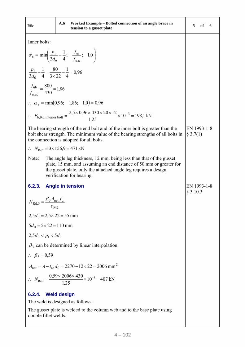
Title A.6 Worked Example – Bolted connection of an angle brace in
tension to a gusset plate 5 of 6
4 – 102
Inner bolts:
0,1;;
4
1
3min
acu,
ub
0
1b f
f
d
p
96,04
1
223
80
4
1
3 0
1
d
p
86,1430
800
acu,
ub f
f
96,00,1;86,1;96,0minb
kN 1,1981025,1
122043096,05,2 3boltinterior Rd,b,
F
The bearing strength of the end bolt and of the inner bolt is greater than the bolt shear strength. The minimum value of the bearing strengths of all bolts in the connection is adopted for all bolts.
EN 1993-1-8 § 3.7(1)
kN 4719,1563Rd,2 N
Note: The angle leg thickness, 12 mm, being less than that of the gusset plate, 15 mm, and assuming an end distance of 50 mm or greater for the gusset plate, only the attached angle leg requires a design verification for bearing.
6.2.3. Angle in tension EN 1993-1-8 § 3.10.3
M2
unet3Rd,3
fAN
mm 55225,25,2 0 d
mm 1102255 0 d
010 55,2 dpd
3 can be determined by linear interpolation:
59,03
20acnet mm 200622122270 dtAA
kN 4071025,1
430200659,0 3Rd,3
N
6.2.4. Weld design
The weld is designed as follows:
The gusset plate is welded to the column web and to the base plate using double fillet welds.
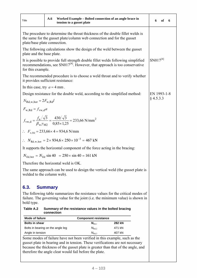
Title A.6 Worked Example – Bolted connection of an angle brace in
tension to a gusset plate 6 of 6
4 – 103
The procedure to determine the throat thickness of the double fillet welds is the same for the gusset plate/column web connection and for the gusset plate/base plate connection.
The following calculations show the design of the weld between the gusset plate and the base plate.
It is possible to provide full strength double fillet welds following simplified recommendations, see SN017[4]. However, that approach is too conservative for this example.
SN017[4]
The recommended procedure is to choose a weld throat and to verify whether it provides sufficient resistance:
In this case, try mm 4a .
Design resistance for the double weld, according to the simplified method:
lFN Rdw,horw,Rd, 2
afF dvw,Rdw,
EN 1993-1-8 § 4.5.3.3
2
M2w
udvw, N/mm 66,233
25,185,0
34303
f
f
N/mm 6,934466,233Rdw, F
kN 467102506,9342 3horw,Rd, N
It supports the horizontal component of the force acting in the bracing:
kN 16140sin25040sinEdhorEd, NN
Therefore the horizontal weld is OK.
The same approach can be used to design the vertical weld (the gusset plate is welded to the column web).
6.3. Summary
The following table summarizes the resistance values for the critical modes of failure. The governing value for the joint (i.e. the minimum value) is shown in bold type.
Table A.2 Summary of the resistance values in the bolted bracing connection
Mode of failure Component resistance
Bolts in shear NRd,1 282 kN
Bolts in bearing on the angle leg NRd,2 471 kN
Angle in tension NRd,3 407 kN
Some modes of failure have not been verified in this example, such as the gusset plate in bearing and in tension. These verifications are not necessary because the thickness of the gusset plate is greater than that of the angle, and therefore the angle cleat would fail before the plate.
STEEL BUILDINGS IN EUROPE
Multi-Storey Steel Buildings
Part 5: Joint Design
.

Multi-Storey Steel Buildings
Part 5: Joint Design

5 - ii
Part 5: Joint Design
5 - iii
FOREWORD
This publication is part five of a design guide, Multi-Storey Steel Buildings.
The 10 parts in the Multi-Storey Steel Buildings guide are:
Part 1: Architect’s guide
Part 2: Concept design
Part 3: Actions
Part 4: Detailed design
Part 5: Joint design
Part 6: Fire Engineering
Part 7: Model construction specification
Part 8: Description of member resistance calculator
Part 9: Description of simple connection resistance calculator
Part 10: Guidance to developers of software for the design of composite beams
Multi-Storey Steel Buildings is one of two design guides. The second design guide is Single Storey Steel Buildings.
The two design guides have been produced in the framework of the European project “Facilitating the market development for sections in industrial halls and low rise buildings (SECHALO) RFS2-CT-2008-0030”.
The design guides have been prepared under the direction of Arcelor Mittal, Peiner Träger and Corus. The technical content has been prepared by CTICM and SCI, collaborating as the Steel Alliance.

Part 5: Joint Design
5 - iv
Part 5: Joint Design
5 - v
Contents
Page No
FOREWORD III
SUMMARY VII
1 INTRODUCTION 1 1.1 About this design guide 1 1.2 Joint behaviour 1 1.3 Standardised joints 2 1.4 Tying resistance 3 1.5 Design guidance in this publication 3 1.6 Symbols 4
2 PARTIAL DEPTH END PLATE 5 2.1 Recommended details 5 2.2 Checks for vertical shear 6 2.3 Checks for tying 12 2.4 Worked Example – Partial depth end plate 14
3 FIN PLATE 21 3.1 Recommended details 21 3.2 Checks for vertical shear 22 3.3 Checks for tying 33 3.4 Worked Example: Fin Plate 38
4 DOUBLE ANGLE WEB CLEATS 51 4.1 Recommended details 51 4.2 Checks for vertical shear 52 4.3 Checks for tying 63 4.4 Worked Example: Angle Web Cleats 68
5 COLUMN SPLICES (BEARING TYPE) 83 5.1 Recommended details 83 5.2 Checks for tension 86 5.3 Check for horizontal shear 91 5.4 Checks for vertical tying 91 5.5 Worked Example – Column Splice 93
6 COLUMN BASES 101 6.1 Base plate size 101 6.2 Calculation of c 102 6.3 Base plate thickness 103 6.4 Base plate welds 104 6.5 Worked Example – Column base 105
APPENDIX A LATERAL TORSIONAL BUCKLING STRENGTH 108
REFERENCES 109

Part 5: Joint Design
5 - vi
Part 5: Joint Design
5 - vii
SUMMARY
This design guide gives the design procedure for simple joints in multi-storey buildings according to the Eurocodes.
The guide covers different types of joints:
Beam-to-beam and beam-to-column joints
Partial depth flexible end plate
Fin plate
Double angle web cleats
Column splices
Column bases
Each design procedure is illustrated by a worked example, using the recommended values given in the Eurocodes.

Part 5: Joint Design
5 - viii
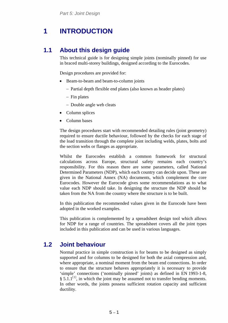
Part 5: Joint Design
5 – 1
1 INTRODUCTION
1.1 About this design guide This technical guide is for designing simple joints (nominally pinned) for use in braced multi-storey buildings, designed according to the Eurocodes.
Design procedures are provided for:
Beam-to-beam and beam-to-column joints
Partial depth flexible end plates (also known as header plates)
Fin plates
Double angle web cleats
Column splices
Column bases
The design procedures start with recommended detailing rules (joint geometry) required to ensure ductile behaviour, followed by the checks for each stage of the load transition through the complete joint including welds, plates, bolts and the section webs or flanges as appropriate.
Whilst the Eurocodes establish a common framework for structural calculations across Europe, structural safety remains each country’s responsibility. For this reason there are some parameters, called National Determined Parameters (NDP), which each country can decide upon. These are given in the National Annex (NA) documents, which complement the core Eurocodes. However the Eurocode gives some recommendations as to what value each NDP should take. In designing the structure the NDP should be taken from the NA from the country where the structure is to be built.
In this publication the recommended values given in the Eurocode have been adopted in the worked examples.
This publication is complemented by a spreadsheet design tool which allows for NDP for a range of countries. The spreadsheet covers all the joint types included in this publication and can be used in various languages.
1.2 Joint behaviour Normal practice in simple construction is for beams to be designed as simply supported and for columns to be designed for both the axial compression and, where appropriate, a nominal moment from the beam end connections. In order to ensure that the structure behaves appropriately it is necessary to provide ‘simple’ connections (‘nominally pinned’ joints) as defined in EN 1993-1-8, § 5.1.1[1], in which the joint may be assumed not to transfer bending moments. In other words, the joints possess sufficient rotation capacity and sufficient ductility.
Part 5: Joint Design
5 – 2
Nominally pinned joints have the following characteristics:
1. they are assumed to transfer only the design shear reaction between members
2. they are capable of accepting the resulting rotation
3. they provide the directional restraint to members which has been assumed in the member design
4. they have sufficient robustness to satisfy the structural integrity requirements.
EN 1993-1-8[1] provides two methods to classify joints: stiffness and strength.
Classification by stiffness: the initial rotational stiffness of the joint, calculated in accordance with Section 6.3.1 of EN 1993-1-8 is compared with the classification boundaries given in Section 5.2 of the same document.
Classification by strength: the following two requirements must be satisfied in order to classify a joint as pinned:
the moment resistance of the joint does not exceed 25% of the moment resistance required for a full-strength joint
the joint is capable of accepting the rotation resulting from the design loads.
Alternatively, joints may also be classified based on experimental evidence, experience of previous satisfactory performance in similar cases or by calculations based on test evidence.
Generally, the requirements for nominally pinned behaviour are met by the use of relatively thin plates, combined with full strength welds. Experience and testing have demonstrated that the use of 8 mm or 10 mm end plates, fin plates and angles in S275, with M20 8.8 bolts leads to connections which behave as nominal pins. If details are chosen outside these recommended parameters, the connection should be classified in accordance with EN 1993-1-8.
1.3 Standardised joints In a typical braced multi-storey frame, the joints may account for less than 5% of the frame weight, but 30% or more of the total cost. Efficient joints will therefore have the lowest detailing, fabrication and erection labour content – they will not necessarily be the lightest.
Use of standardised joints where the fittings, bolts, welds and geometry are fully defined offers the following benefits:
Reduces buying, storage, and handling time
Improves availability and leads to a reduction in material costs
Saves fabrication time and leads to faster erection
Leads to a better understanding of their performance by all sides of the industry
Part 5: Joint Design
5 – 3
Leads to fewer errors.
To take advantage of these benefits, standardised joints are recommended in this publication. A summary of the typical components adopted in this guide is as follows:
Material of grade S275 for components such as end plates and cleats
M20 8.8 fully threaded bolts, 60 mm long
22 mm holes, punched or drilled
Fillet welds of 6 mm or 8 mm leg length
Distance from the top of the beam to the first bolt row of 90 mm
Vertical bolt spacing (pitch) of 70 mm
Horizontal bolt spacing (gauge) of 90 or 140 mm
Top of partial depth end plate, cleat or fin plate is 50 mm below the top of the beam flange.
1.4 Tying resistance The requirement for sufficient tying resistance is to safeguard the structure against disproportionate collapse. Guidance on the design tying force that a connection must carry is given in EN 1991-1-7 Annex A[2].
EN 1993-1-8 does not give any guidance on how to calculate the tying resistance of joints. Other authoritative sources[3] recommend that the ultimate tensile strength (fu) should be used for calculating the tying resistance and the partial factor for tying Mu should be taken as 1,10. This value applies to the design resistance of all components of the joint: welds, bolts, plate and beam.
1.5 Design guidance in this publication In this publication, design checks are presented followed in each case by a numerical worked example. The guidance covers:
partial depth flexible end plates
fin plates
double angle web cleats
column splices
column bases.
In all worked examples, the section headings correspond to the headings in the design procedure preceeding each workded example.
Part 5: Joint Design
5 – 4
1.6 Symbols a is the throat of the fillet weld
b is the breadth of the supported beam
d is the diameter of the bolt
d0 is the diameter of the hole
fy,b is the yield strength of the supported beam
fu,b is the ultimate tensile strength of the supported beam
fy,p is the yield strength of the plate (end plate, fin plate, flange cover plate, base plate)
fu,p is the ultimate tensile strength of the plate (end plate, fin plate, flange cover plate, base plate)
fy,ac is the yield strength of the angle cleats
fu,ac is the ultimate tensile strength of the angle cleats
fub is the ultimate tensile strength of the bolt
hb is the height of the supported beam
hp is the height of the plate (end plate, fin plate, flange cover plate)
hac is the height of the angle cleats
nb is the total number of bolts on supported beam side
ns is the total number of bolts on supporting beam side
n1 is the number of horizontal bolt rows
n2 is the number of vertical bolt rows
tf is the flange thickness of the supported beam
tw is the thickness of the supported beam web
tp is the thickness of the plate (End plate, Fin plate, Flange cover plate, Base plate)
tac is the thickness of the angle cleats
s is the leg length of the fillet weld
M0 is the partial factor for the resistance of cross section (M0 = 1,0 is recommended in EN 1993-1-1)
M1 is the partial factor for the resistance of members to instability assessed by member checks (M1 = 1,0 is recommended in EN 1993-1-1)
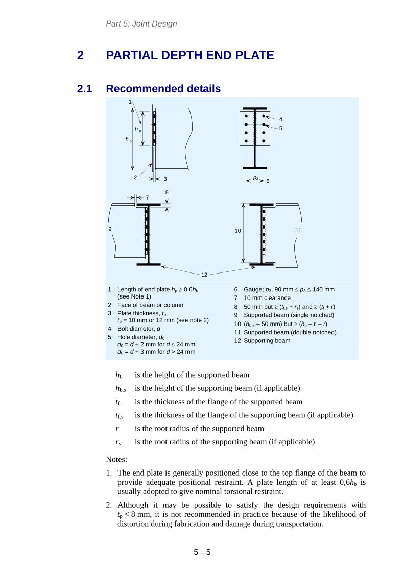
Part 5: Joint Design
5 – 5
2 PARTIAL DEPTH END PLATE
2.1 Recommended details
h
h
3p
b
p
1
5
4
2 3 6
11
87
10
12
9
1 Length of end plate hp 0,6hb (see Note 1)
2 Face of beam or column 3 Plate thickness, tp
tp = 10 mm or 12 mm (see note 2) 4 Bolt diameter, d 5 Hole diameter, d0
d0 = d + 2 mm for d 24 mm d0 = d + 3 mm for d > 24 mm
6 Gauge; p3, 90 mm p3 140 mm 7 10 mm clearance
8 50 mm but (tf,s + rs) and (tf + r) 9 Supported beam (single notched)
10 (hb,s – 50 mm) but (hb – tf – r) 11 Supported beam (double notched) 12 Supporting beam
hb is the height of the supported beam
hb,s is the height of the supporting beam (if applicable)
tf is the thickness of the flange of the supported beam
tf,s is the thickness of the flange of the supporting beam (if applicable)
r is the root radius of the supported beam
rs is the root radius of the supporting beam (if applicable)
Notes:
1. The end plate is generally positioned close to the top flange of the beam to provide adequate positional restraint. A plate length of at least 0,6hb is usually adopted to give nominal torsional restraint.
2. Although it may be possible to satisfy the design requirements with tp < 8 mm, it is not recommended in practice because of the likelihood of distortion during fabrication and damage during transportation.
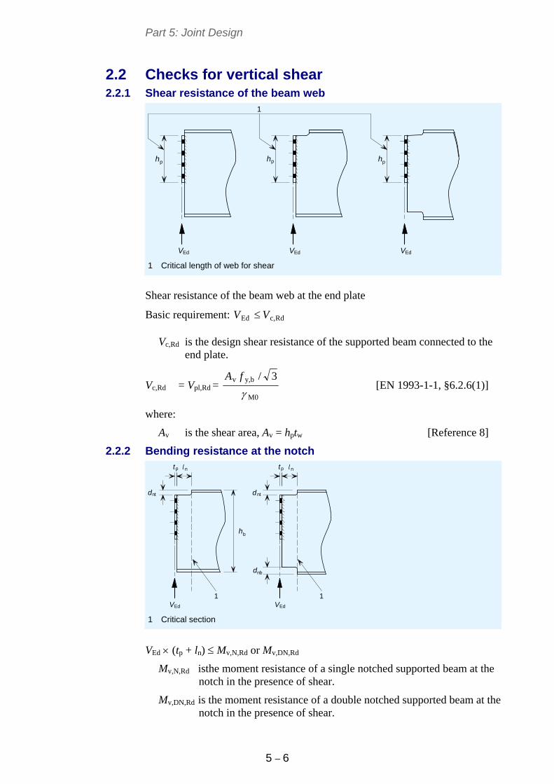
Part 5: Joint Design
5 – 6
2.2 Checks for vertical shear 2.2.1 Shear resistance of the beam web
h h h
Ed EdEd
p p p
V V V
1
1 Critical length of web for shear
Shear resistance of the beam web at the end plate
Basic requirement: Rdc,Ed VV
Vc,Rd is the design shear resistance of the supported beam connected to the end plate.
Vc,Rd = Vpl,Rd = M0
by,v 3/
fA
[EN 1993-1-1, §6.2.6(1)]
where:
Av is the shear area, Av = hptw [Reference 8]
2.2.2 Bending resistance at the notch
h
p p
d d
d
EdEd
nt
nt nt
nt
nb
l l
V V
b
1 1
1 Critical section
VEd (tp + ln) Mv,N,Rd or Mv,DN,Rd
Mv,N,Rd isthe moment resistance of a single notched supported beam at the notch in the presence of shear.
Mv,DN,Rd is the moment resistance of a double notched supported beam at the notch in the presence of shear.
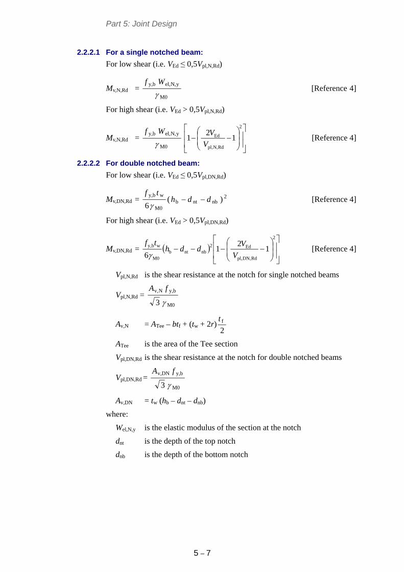
Part 5: Joint Design
5 – 7
2.2.2.1 For a single notched beam:
For low shear (i.e. VEd ≤ 0,5Vpl,N,Rd)
Mv,N,Rd = M0
yN,el,by,
Wf
[Reference 4]
For high shear (i.e. VEd > 0,5Vpl,N,Rd)
Mv,N,Rd = M0
yN,el,by,
Wf
2
RdN,pl,
Ed 1
21
V
V [Reference 4]
2.2.2.2 For double notched beam:
For low shear (i.e. VEd ≤ 0,5Vpl,DN,Rd)
Mv,DN,Rd = 2nbntb
M0
wby,)(
6ddh
tf
[Reference 4]
For high shear (i.e. VEd > 0,5Vpl,DN,Rd)
Mv,DN,Rd =
2
RdDN,pl,
Ed2nbntb
M0
wby, 1
21
6 V
Vddh
tf
[Reference 4]
Vpl,N,Rd is the shear resistance at the notch for single notched beams
Vpl,N,Rd = M0
by,Nv,
3
fA
Av,N = ATee – btf + (tw + 2r)2ft
ATee is the area of the Tee section
Vpl,DN,Rd is the shear resistance at the notch for double notched beams
Vpl,DN,Rd = M0
by,DNv,
3
fA
Av,DN = tw (hb – dnt – dnb)
where:
Wel,N,y is the elastic modulus of the section at the notch
dnt is the depth of the top notch
dnb is the depth of the bottom notch
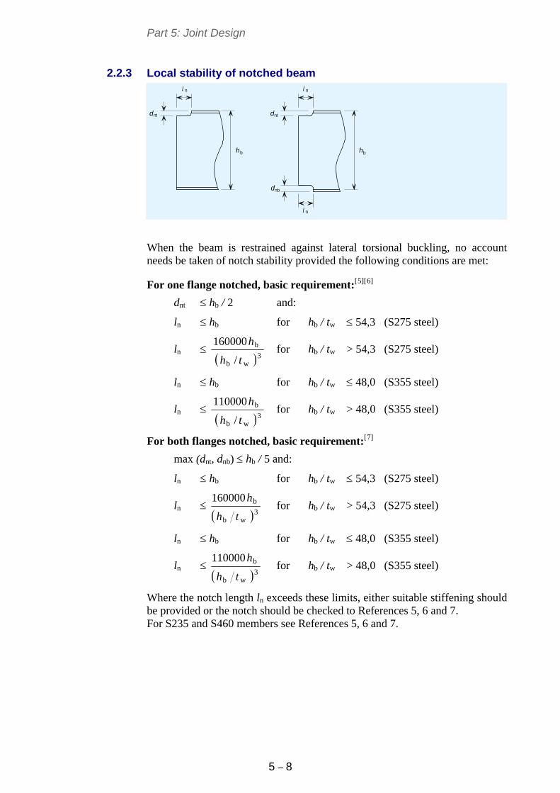
Part 5: Joint Design
5 – 8
2.2.3 Local stability of notched beam
h h
d d
d
nt
n
nn
nt
l l
l
nb
b b
When the beam is restrained against lateral torsional buckling, no account needs be taken of notch stability provided the following conditions are met:
For one flange notched, basic requirement:[5][6]
dnt hb / 2 and:
ln hb for hb / tw 54,3 (S275 steel)
ln 3
wb
b
/
160000
th
h for hb / tw > 54,3 (S275 steel)
ln hb for hb / tw 48,0 (S355 steel)
ln 3
wb
b
/
110000
th
h for hb / tw > 48,0 (S355 steel)
For both flanges notched, basic requirement:[7]
max (dnt, dnb) hb / 5 and:
ln hb for hb / tw 54,3 (S275 steel)
ln 3
wb
b160000
th
h for hb / tw > 54,3 (S275 steel)
ln hb for hb / tw 48,0 (S355 steel)
ln 3
wb
b110000
th
h for hb / tw > 48,0 (S355 steel)
Where the notch length ln exceeds these limits, either suitable stiffening should be provided or the notch should be checked to References 5, 6 and 7. For S235 and S460 members see References 5, 6 and 7.
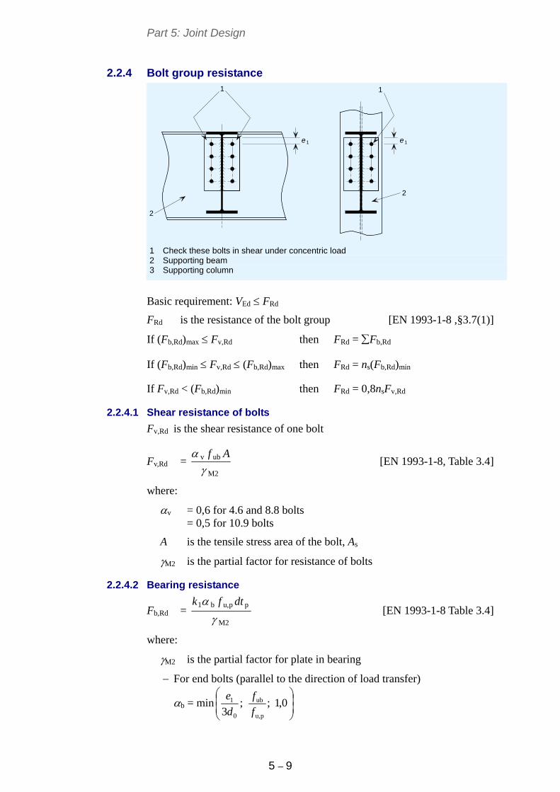
Part 5: Joint Design
5 – 9
2.2.4 Bolt group resistance
ee 11
2
2
1 1
1 Check these bolts in shear under concentric load 2 Supporting beam 3 Supporting column
Basic requirement: VEd FRd
FRd is the resistance of the bolt group [EN 1993-1-8 ,§3.7(1)]
If (Fb,Rd)max Fv,Rd then FRd = Fb,Rd
If (Fb,Rd)min Fv,Rd (Fb,Rd)max then FRd = ns(Fb,Rd)min
If Fv,Rd < (Fb,Rd)min then FRd = 0,8nsFv,Rd
2.2.4.1 Shear resistance of bolts
Fv,Rd is the shear resistance of one bolt
Fv,Rd = M2
ubv
Af
[EN 1993-1-8, Table 3.4]
where:
v = 0,6 for 4.6 and 8.8 bolts = 0,5 for 10.9 bolts
A is the tensile stress area of the bolt, As
M2 is the partial factor for resistance of bolts
2.2.4.2 Bearing resistance
Fb,Rd = M2
ppu,b1
dtfk
[EN 1993-1-8 Table 3.4]
where:
M2 is the partial factor for plate in bearing
For end bolts (parallel to the direction of load transfer)
b = min
0,1;;
3 pu,
ub
0
1
f
f
d
e
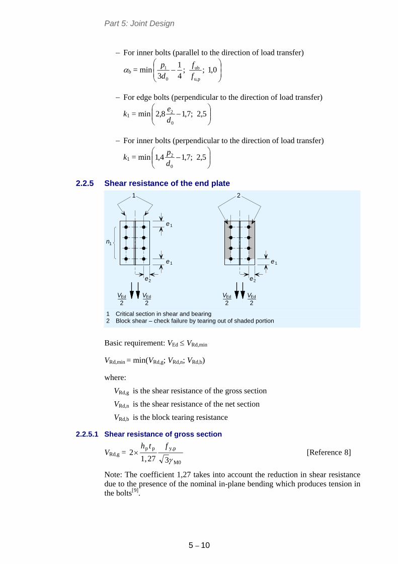
Part 5: Joint Design
5 – 10
For inner bolts (parallel to the direction of load transfer)
b = min
0,1;;
4
1
3 pu,
ub
0
1
f
f
d
p
For edge bolts (perpendicular to the direction of load transfer)
k1 = min
5,2;7,18,2
0
2
d
e
For inner bolts (perpendicular to the direction of load transfer)
k1 = min
5,2;7,14,1
0
2
d
p
2.2.5 Shear resistance of the end plate
e
e e
1
1 1
2
e e2 2
Ed
2Ed
2Ed
2EdV V V V
n1
1 2
1 Critical section in shear and bearing 2 Block shear – check failure by tearing out of shaded portion
Basic requirement: VEd VRd,min
VRd,min = min(VRd,g; VRd,n; VRd,b)
where:
VRd,g is the shear resistance of the gross section
VRd,n is the shear resistance of the net section
VRd,b is the block tearing resistance
2.2.5.1 Shear resistance of gross section
VRd,g = M0
py,pp
327,12
fth [Reference 8]
Note: The coefficient 1,27 takes into account the reduction in shear resistance due to the presence of the nominal in-plane bending which produces tension in the bolts[9].
Part 5: Joint Design
5 – 11
2.2.5.2 Shear resistance of net section
VRd,n = M2
pu,netv,
32
fA [Reference 8]
Av,net = 01pp dnht
M2 is the partial factor for the resistance of net sections
2.2.5.3 Block tearing resistance
VRd,b =
M0
nvpy,
M2
ntpu,
32
AfAf
[Reference 8]
But if hp < 1.36p3 and n1 > 1 then:
VRd,b =
M0
nvpy,
M2
ntpu,
3
5,02
AfAf
Ant = 02p 5,0 det
Anv = 011pp )5,0( dneht
where:
p3 is the gauge (cross centres)
2.2.6 Weld resistance
Full strength symmetrical fillet welds are recommended.
For a full strength weld, the size of each throat should comply with the following requirement[8]:
a ≥ 0,46 tw for S235 supported beam
a ≥ 0,48 tw for S275 supported beam
a ≥ 0,55 tw for S355 supported beam
a ≥ 0,74 tw for S460 supported beam
where:
a is the effective weld throat thickness
The leg length is defined as follows: 2as
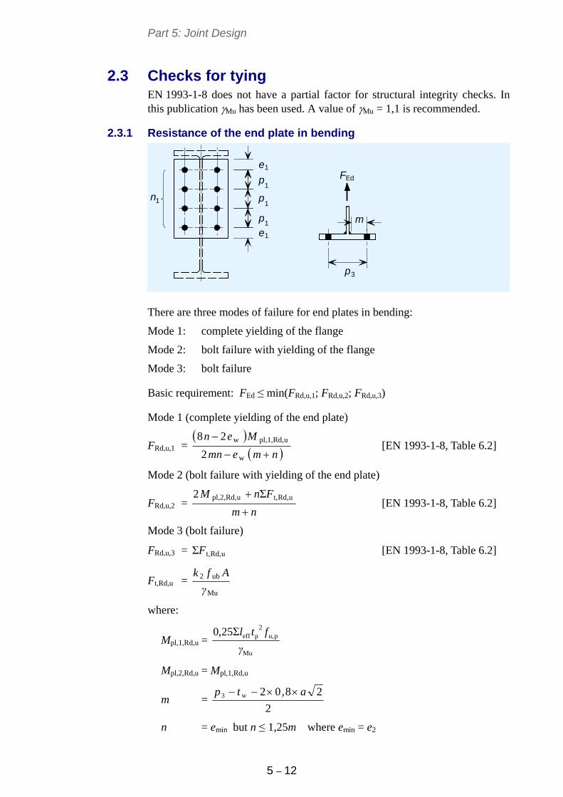
Part 5: Joint Design
5 – 12
2.3 Checks for tying EN 1993-1-8 does not have a partial factor for structural integrity checks. In this publication Mu has been used. A value of Mu = 1,1 is recommended.
2.3.1 Resistance of the end plate in bending
1
1
1
1
1
m
p3
e
p
p
p
e
FEd
n1
There are three modes of failure for end plates in bending:
Mode 1: complete yielding of the flange
Mode 2: bolt failure with yielding of the flange
Mode 3: bolt failure
Basic requirement: FEd ≤ min(FRd,u,1; FRd,u,2; FRd,u,3)
Mode 1 (complete yielding of the end plate)
FRd,u,1 =
nmemn
Men
w
uRd,pl,1,w
2
28 [EN 1993-1-8, Table 6.2]
Mode 2 (bolt failure with yielding of the end plate)
FRd,u,2 = nm
FnM
uRd,t,uRd,pl,2, Σ2 [EN 1993-1-8, Table 6.2]
Mode 3 (bolt failure)
FRd,u,3 = uRd,t,ΣF [EN 1993-1-8, Table 6.2]
Ft,Rd,u = Mu
ub2
γ
Afk
where:
Mpl,1,Rd,u = Mu
pu,2
peffΣ25,0
γ
ftl
Mpl,2,Rd,u = Mpl,1,Rd,u
m = 2
28,02w3 atp
n = emin but n ≤ 1,25m where emin = e2
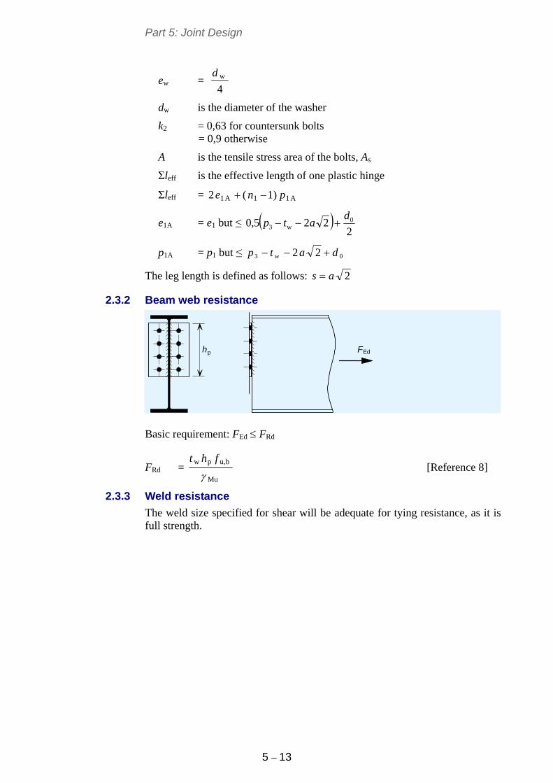
Part 5: Joint Design
5 – 13
ew = 4wd
dw is the diameter of the washer
k2 = 0,63 for countersunk bolts = 0,9 otherwise
A is the tensile stress area of the bolts, As
Σleff is the effective length of one plastic hinge
Σleff = A11A1 )1(2 pne
e1A = e1 but ≤ 2
225,0 0w3
datp
p1A = p1 but ≤ 0w3 22 datp
The leg length is defined as follows: 2as
2.3.2 Beam web resistance
p Fh Ed
Basic requirement: FEd FRd
FRd = Mu
bu,pw
fht
[Reference 8]
2.3.3 Weld resistance
The weld size specified for shear will be adequate for tying resistance, as it is full strength.
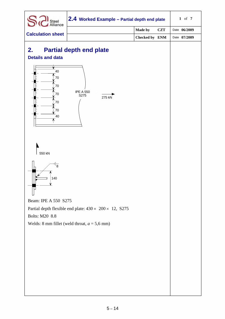
5 – 14
2.4 Worked Example – Partial depth end plate 1 of 7
Made by CZT Date 06/2009
Calculation sheet Checked by ENM Date 07/2009
2. Partial depth end plate
Details and data
140
70
70
70
70
70
40
40
550 kN
275 kN
IPE A 550S275
8
Beam: IPE A 550 S275
Partial depth flexible end plate: 430 200 12, S275
Bolts: M20 8.8
Welds: 8 mm fillet (weld throat, a = 5,6 mm)
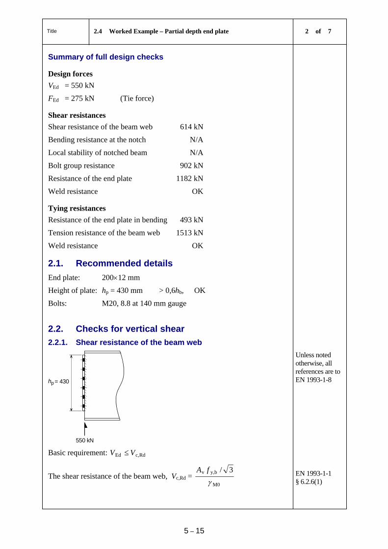
Title 2.4 Worked Example – Partial depth end plate 2 of 7
5 – 15
Summary of full design checks
Design forces
VEd = 550 kN
FEd = 275 kN (Tie force)
Shear resistances
Shear resistance of the beam web 614 kN
Bending resistance at the notch N/A
Local stability of notched beam N/A
Bolt group resistance 902 kN
Resistance of the end plate 1182 kN
Weld resistance OK
Tying resistances
Resistance of the end plate in bending 493 kN
Tension resistance of the beam web 1513 kN
Weld resistance OK
2.1. Recommended details
End plate: 20012 mm
Height of plate: hp = 430 mm > 0,6hb, OK
Bolts: M20, 8.8 at 140 mm gauge
2.2. Checks for vertical shear
2.2.1. Shear resistance of the beam web
= 430
550 kN
ph
Unless noted otherwise, all references are to EN 1993-1-8
Basic requirement: Rdc,Ed VV
The shear resistance of the beam web, Vc,Rd = M0
by,v 3/
fA
EN 1993-1-1 § 6.2.6(1)
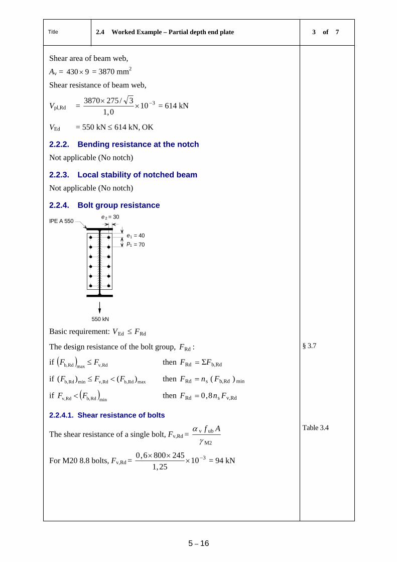
Title 2.4 Worked Example – Partial depth end plate 3 of 7
5 – 16
Shear area of beam web,
Av = 9430 = 3870 mm2
Shear resistance of beam web,
Vpl,Rd = 3100,1
3/2753870
= 614 kN
VEd = 550 kN 614 kN, OK
2.2.2. Bending resistance at the notch
Not applicable (No notch)
2.2.3. Local stability of notched beam
Not applicable (No notch)
2.2.4. Bolt group resistance
2
1
1
550 kN
e
ep
= 40
= 70
= 30IPE A 550
Basic requirement: RdEd FV
The design resistance of the bolt group, RdF :
if Rdv,maxRdb, FF then Rdb,Rd ΣFF
§ 3.7
if maxRdb,Rdv,minRdb, )()( FFF then minRdb,sRd )( FnF
if minRdb,Rdv, FF then Rdv,sRd 8,0 FnF
2.2.4.1. Shear resistance of bolts
The shear resistance of a single bolt, Fv,Rd = M2
ubv
Af
Table 3.4
For M20 8.8 bolts, Fv,Rd = 31025,1
2458006,0
= 94 kN
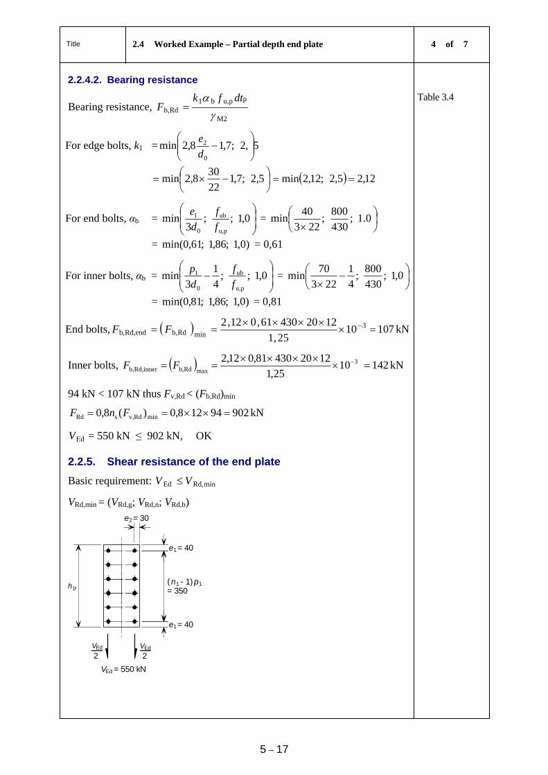
Title 2.4 Worked Example – Partial depth end plate 4 of 7
5 – 17
2.2.4.2. Bearing resistance
Bearing resistance, M2
ppu,b1Rdb,
dtfkF
Table 3.4
For edge bolts, k1 = 5,2;7,18,2min0
2
d
e
5,2;7,1
22
308,2min 12,25,2;12,2min
For end bolts, αb =
0,1;;
3min
pu,
ub
0
1
f
f
d
e =
0.1;
430
800;
223
40min
= )0,1;86,1;61,0min( = 0,61
For inner bolts, αb =
0,1;;
4
1
3min
pu,
ub
0
1
f
f
d
p =
0,1;
430
800;
4
1
223
70min
= )0,1;86,1;81,0min( = 0,81
End bolts, 3minRdb,endRd,b, 10
25,1
122043061,012,2
FF 107 kN
Inner bolts, 3
maxRdb,innerRd,b, 1025,1
122043081,012,2
FF 142 kN
94 kN < 107 kN thus Fv,Rd < (Fb,Rd)min
90294128,0)(8,0 minRdv,sRd FnF kN
EdV = 550 kN ≤ 902 kN, OK
2.2.5. Shear resistance of the end plate
Basic requirement: minRd,Ed VV
VRd,min = (VRd,g; VRd,n; VRd,b)
1
1
2 2
Ed
Ed Ed
ph
V V
V
e
e
e
= 40
= 40
= 302
n - 1)( p1
= 350
= 550 kN
1
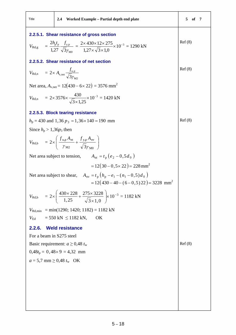
Title 2.4 Worked Example – Partial depth end plate 5 of 7
5 – 18
2.2.5.1. Shear resistance of gross section
VRd,g = M0
py,pp
327,1
2
fth
= 3100,1327,1
275124302
= 1290 kN Ref (8)
2.2.5.2. Shear resistance of net section
VRd,n = M2
pu,netv,
32
f
A Ref (8)
Net area, Av,net = 22643012 = 3576 mm2
VRd,n = 31025,13
43035762
= 1420 kN
2.2.5.3. Block tearing resistance
hp = 430 and 19014036,136,1 3 p mm
Since hp > 1,36p3 then
Ref (8)
VRd,b =
M0
nvpy,
M2
ntpu,
32
AfAf
Net area subject to tension, 02pnt 5,0 detA
228225,03012 mm2
Net area subject to shear, 011ppnv )5,0( dnehtA
322822)5,06(4043012 mm2
VRd,b = 3100,13
3228275
25,1
2284302
= 1182 kN
VRd,min = min(1290; 1420; 1182) = 1182 kN
VEd = 550 kN ≤ 1182 kN, OK
2.2.6. Weld resistance
For a beam in S275 steel
Basic requirement: a ≥ 0,48 tw Ref (8)
0,48tp = 948,0 = 4,32 mm
a = 5,7 mm ≥ 0,48 tw OK
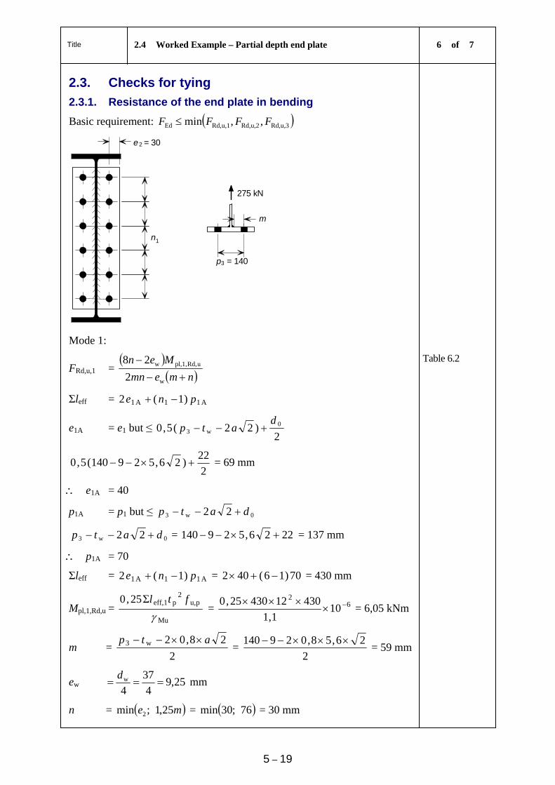
Title 2.4 Worked Example – Partial depth end plate 6 of 7
5 – 19
2.3. Checks for tying
2.3.1. Resistance of the end plate in bending
Basic requirement: u,3Rd,u,2Rd,u,1Rd,Ed ,,min FFFF
2
3
m
1
p = 140
n
e = 30
275 kN
Mode 1:
FRd,u,1 =
nmemn
Men
w
uRd,pl,1,w
2
28
Table 6.2
Σleff = A11A1 )1(2 pne
e1A = e1 but ≤ 2
)22(5,0 0w3
datp
2
22)26,529140(5,0 = 69 mm
e1A = 40
p1A = p1 but ≤ 0w3 22 datp
0w3 22 datp = 2226,529140 = 137 mm
p1A = 70
Σleff = A11A1 )1(2 pne = 70)16(402 = 430 mm
Mpl,1,Rd,u = Mu
pu,2
peff,1Σ25,0
ftl
= 62
101,1
4301243025,0
= 6,05 kNm
m = 2
28,02w3 atp =
2
26,58,029140 = 59 mm
ew 25,94
37
4w
d mm
n = me 25,1;min 2 = 76;30min = 30 mm
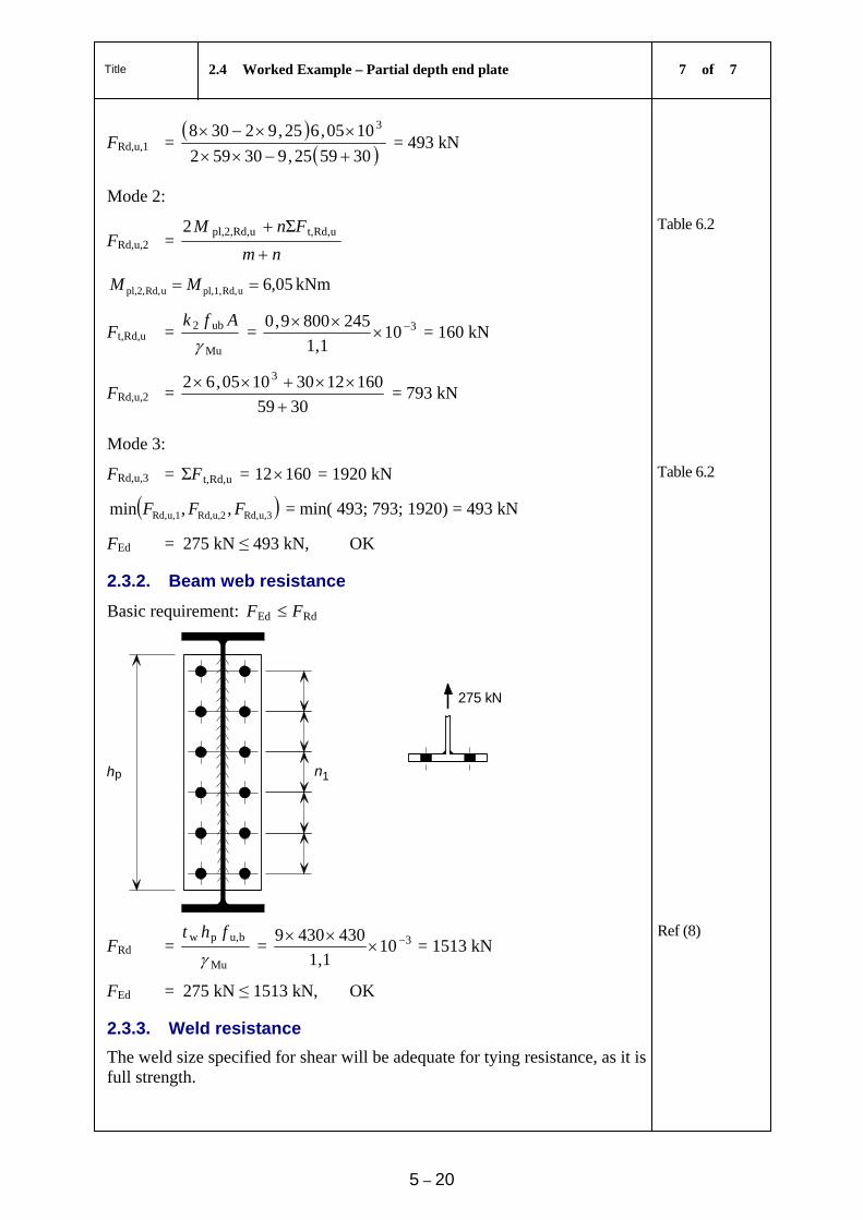
Title 2.4 Worked Example – Partial depth end plate 7 of 7
5 – 20
FRd,u,1 =
305925,930592
1005,625,92308 3
= 493 kN
Mode 2:
FRd,u,2 = nm
FnM
uRd,t,uRd,pl,2, Σ2
Table 6.2
05,6uRd,pl,1,uRd,pl,2, MM kNm
Ft,Rd,u = Mu
ub2
Afk
= 3101,1
2458009,0
= 160 kN
FRd,u,2 = 3059
16012301005,62 3
= 793 kN
Mode 3:
FRd,u,3 = uRd,t,ΣF = 16012 = 1920 kN Table 6.2
u,3Rd,u,2Rd,u,1Rd, ,,min FFF = min( 493; 793; 1920) = 493 kN
FEd = 275 kN ≤ 493 kN, OK
2.3.2. Beam web resistance
Basic requirement: RdEd FF
hp 1n
275 kN
FRd = Mu
bu,pw
fht
= 3101,1
4304309
= 1513 kN Ref (8)
FEd = 275 kN ≤ 1513 kN, OK
2.3.3. Weld resistance
The weld size specified for shear will be adequate for tying resistance, as it is full strength.
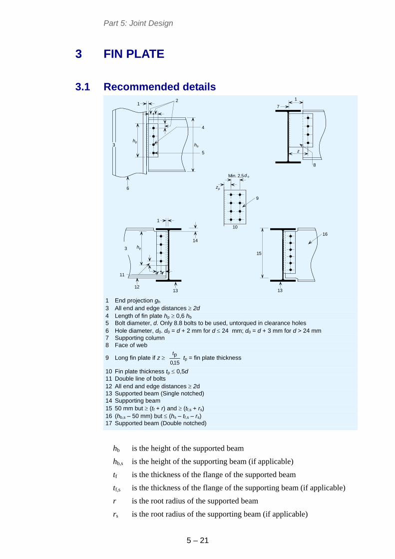
Part 5: Joint Design
5 – 21
3 FIN PLATE
3.1 Recommended details
Min. 2,5
p
p
p
z
d o
h
h
h
z
b
12
3
4
5
1
7
8
9
10
6
13
16
14
15
1312
11
3
1
1 End projection gh 3 All end and edge distances 2d 4 Length of fin plate hp 0,6 hb 5 Bolt diameter, d. Only 8.8 bolts to be used, untorqued in clearance holes 6 Hole diameter, d0. d0 = d + 2 mm for d 24 mm; d0 = d + 3 mm for d > 24 mm 7 Supporting column 8 Face of web
9 Long fin plate if z 15,0
pt tp = fin plate thickness
10 Fin plate thickness tp 0,5d 11 Double line of bolts 12 All end and edge distances 2d 13 Supported beam (Single notched) 14 Supporting beam 15 50 mm but (tf + r) and (tf,s + rs) 16 (hb,s – 50 mm) but (hs – tf,s – rs) 17 Supported beam (Double notched)
hb is the height of the supported beam
hb,s is the height of the supporting beam (if applicable)
tf is the thickness of the flange of the supported beam
tf,s is the thickness of the flange of the supporting beam (if applicable)
r is the root radius of the supported beam
rs is the root radius of the supporting beam (if applicable)
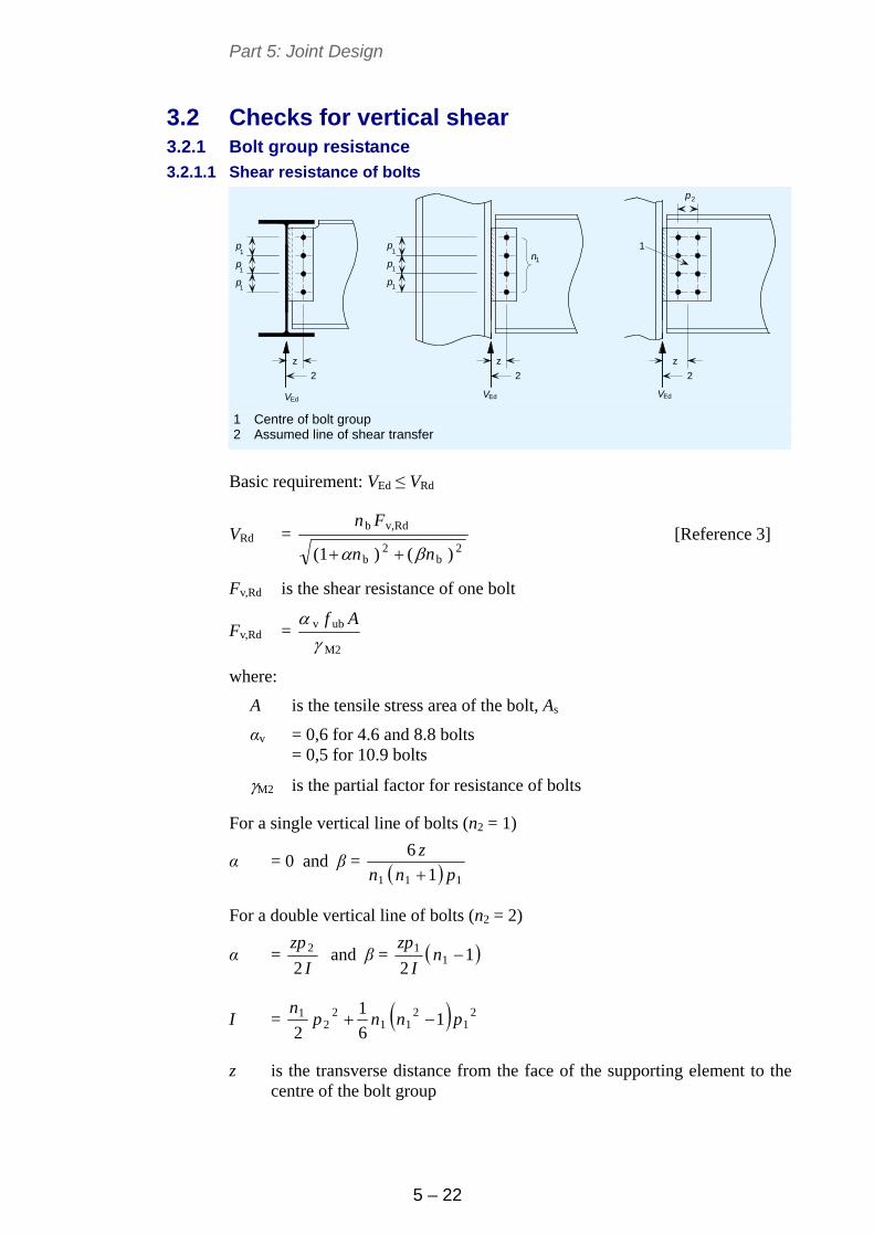
Part 5: Joint Design
5 – 22
3.2 Checks for vertical shear 3.2.1 Bolt group resistance
3.2.1.1 Shear resistance of bolts
VEd
p
p
p
11
1
1
VEd VEd
2
1
1
1
p
zzz
p
p
p
n
2 2 2
1
1 Centre of bolt group 2 Assumed line of shear transfer
Basic requirement: VEd ≤ VRd
VRd = 2
b2
b
Rdv,b
)()(1 nn
Fn
[Reference 3]
Fv,Rd is the shear resistance of one bolt
Fv,Rd = M2
ubv
Af
where:
A is the tensile stress area of the bolt, As
αv = 0,6 for 4.6 and 8.8 bolts = 0,5 for 10.9 bolts
M2 is the partial factor for resistance of bolts
For a single vertical line of bolts (n2 = 1)
α = 0 and β = 111 1
6
pnn
z
For a double vertical line of bolts (n2 = 2)
α = I
zp
22 and β = 1
21
1 nI
zp
I = 21
211
22
1 16
1
2pnnp
n
z is the transverse distance from the face of the supporting element to the centre of the bolt group
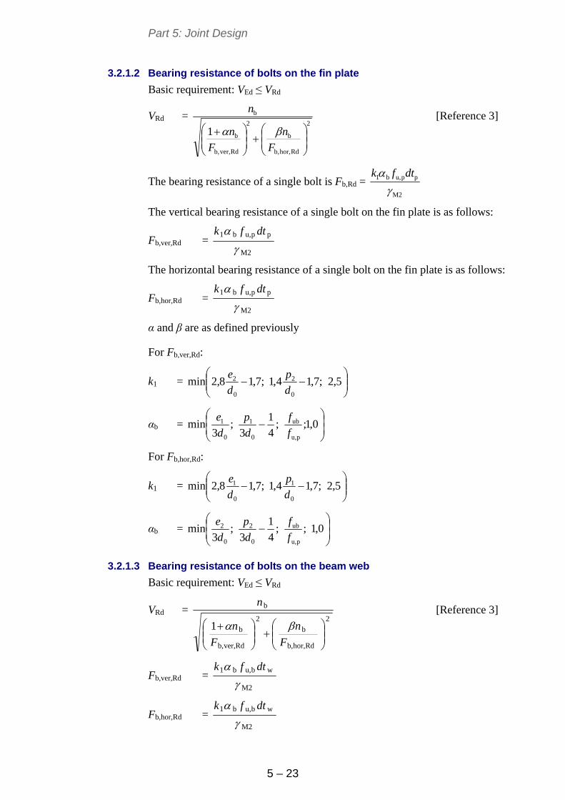
Part 5: Joint Design
5 – 23
3.2.1.2 Bearing resistance of bolts on the fin plate
Basic requirement: VEd ≤ VRd
VRd = 2
Rdhor,b,
b
2
Rdver,b,
b
b
1
F
n
F
n
n
[Reference 3]
The bearing resistance of a single bolt is Fb,Rd = M2
ppu,b1
dtfk
The vertical bearing resistance of a single bolt on the fin plate is as follows:
Fb,ver,Rd = M2
ppu,b1
dtfk
The horizontal bearing resistance of a single bolt on the fin plate is as follows:
Fb,hor,Rd = M2
ppu,b1
dtfk
α and β are as defined previously
For Fb,ver,Rd:
k1 =
5,2;7,14,1;7,18,2min
0
2
0
2
d
p
d
e
αb =
0,1;;
4
1
3;
3min
pu,
ub
0
1
0
1
f
f
d
p
d
e
For Fb,hor,Rd:
k1 =
5,2;7,14,1;7,18,2min
0
1
0
1
d
p
d
e
αb =
0,1;;
4
1
3;
3min
pu,
ub
0
2
0
2
f
f
d
p
d
e
3.2.1.3 Bearing resistance of bolts on the beam web
Basic requirement: VEd ≤ VRd
VRd = 2
Rdhor,b,
b
2
Rdver,b,
b
b
1
F
n
F
n
n
[Reference 3]
Fb,ver,Rd = M2
wbu,b1
dtfk
Fb,hor,Rd = M2
wbu,b1
dtfk
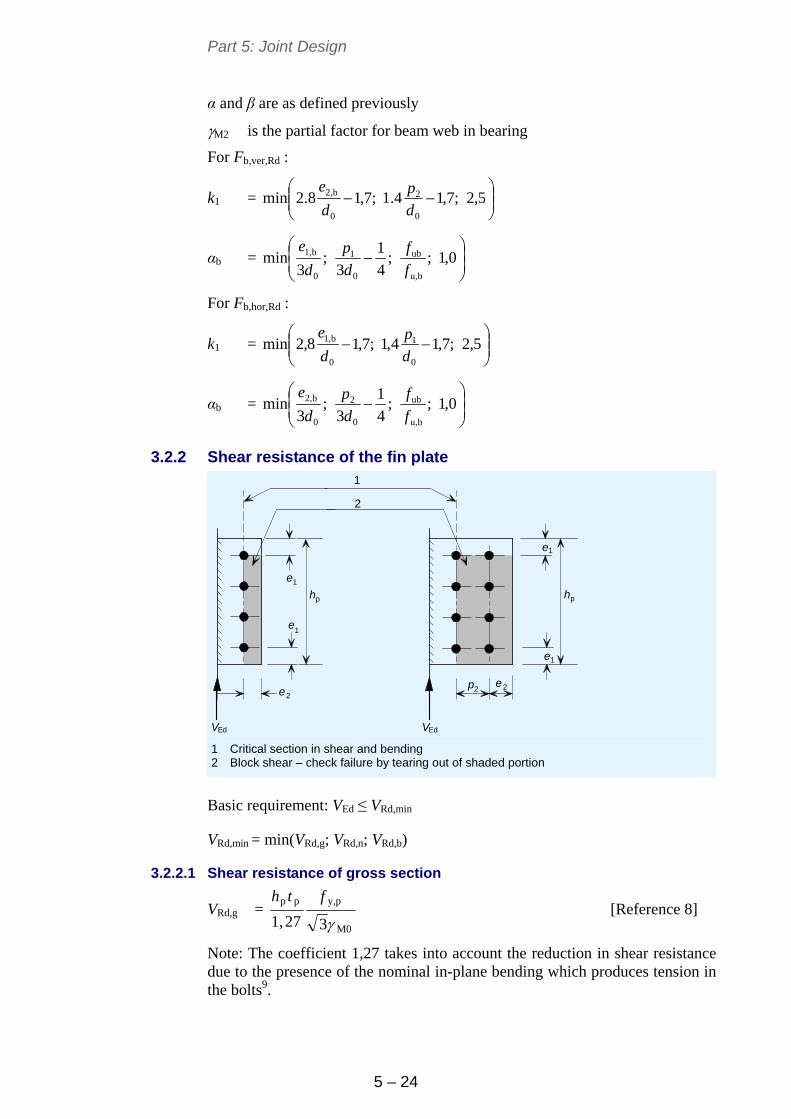
Part 5: Joint Design
5 – 24
α and β are as defined previously
M2 is the partial factor for beam web in bearing
For Fb,ver,Rd :
k1 =
5,2;7,14.1;7,18.2min
0
2
0
b2,
d
p
d
e
αb =
0,1;;
4
1
3;
3min
bu,
ub
0
1
0
b1,
f
f
d
p
d
e
For Fb,hor,Rd :
k1 =
5,2;7,14,1;7,18,2min
0
1
0
b1,
d
p
d
e
αb =
0,1;;
4
1
3;
3min
bu,
ub
0
2
0
b2,
f
f
d
p
d
e
3.2.2 Shear resistance of the fin plate
e
e
1
1
1
1
22e
e
VEd VEd
2p
hphp
2
1
e
e
1 Critical section in shear and bending 2 Block shear – check failure by tearing out of shaded portion
Basic requirement: VEd ≤ VRd,min
VRd,min = min(VRd,g; VRd,n; VRd,b)
3.2.2.1 Shear resistance of gross section
VRd,g = M0
py,pp
327,1
fth [Reference 8]
Note: The coefficient 1,27 takes into account the reduction in shear resistance due to the presence of the nominal in-plane bending which produces tension in the bolts9.
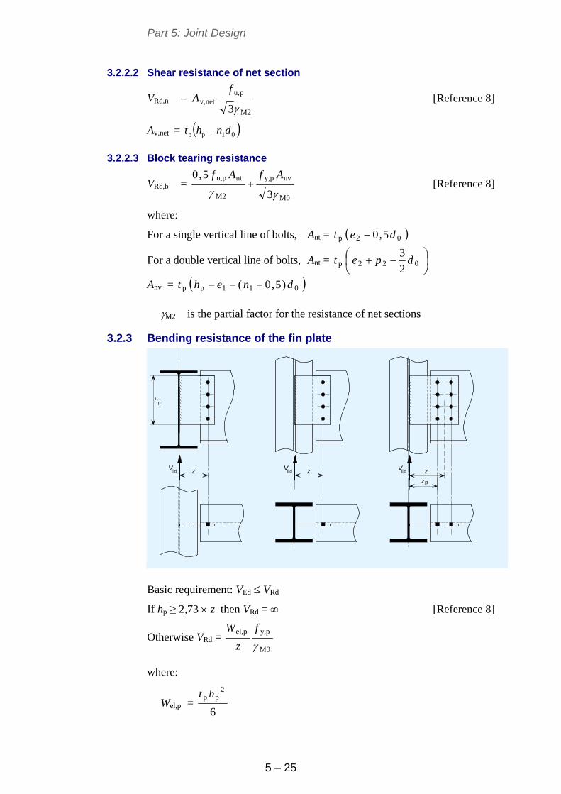
Part 5: Joint Design
5 – 25
3.2.2.2 Shear resistance of net section
VRd,n = M2
pu,netv,
3
fA [Reference 8]
Av,net = 01pp dnht
3.2.2.3 Block tearing resistance
VRd,b = M0
nvpy,
M2
ntpu,
3
5,0
AfAf
[Reference 8]
where:
For a single vertical line of bolts, Ant = 02p 5,0 det
For a double vertical line of bolts, Ant =
022p
2
3dpet
Anv = 011pp )5,0( dneht
M2 is the partial factor for the resistance of net sections
3.2.3 Bending resistance of the fin plate
hp
Ed Ed Edz z z
z
V V V
p
Basic requirement: VEd VRd
If hp ≥ 2,73 z then VRd = [Reference 8]
Otherwise VRd = M0
py,pel,
f
z
W
where:
Wel,p = 6
2pp ht
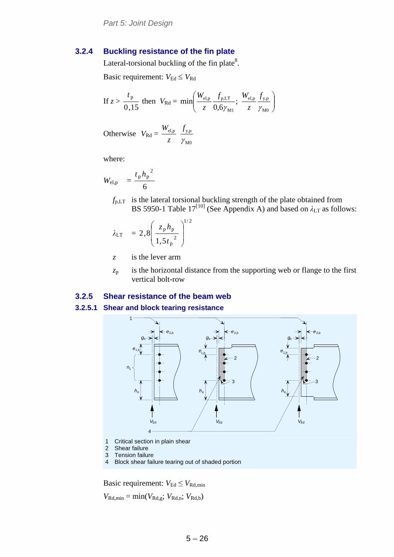
Part 5: Joint Design
5 – 26
3.2.4 Buckling resistance of the fin plate
Lateral-torsional buckling of the fin plate8.
Basic requirement: VEd VRd
If z > 15,0
pt then VRd =
M0
py,pel,
M1
LTp,pel, ;6,0
minf
z
Wf
z
W
Otherwise VRd = M0
py,pel,
f
z
W
where:
Wel,p = 6
2pp ht
fp,LT is the lateral torsional buckling strength of the plate obtained from BS 5950-1 Table 17[10] (See Appendix A) and based on λLT as follows:
λLT =
2/1
2p
pp
5,18,2
t
hz
z is the lever arm
zp is the horizontal distance from the supporting web or flange to the first vertical bolt-row
3.2.5 Shear resistance of the beam web
3.2.5.1 Shear and block tearing resistance
e
e e
e
e
e
gh gh
2,b 2,b 2,b
1,b 1,b
eheh
Ed Ed Ed
he
1,b
V V V
gh
n1
3
2 2
3
4
1
1 Critical section in plain shear 2 Shear failure 3 Tension failure 4 Block shear failure tearing out of shaded portion
Basic requirement: VEd ≤ VRd,min
VRd,min = min(VRd,g; VRd,n; VRd,b)
Part 5: Joint Design
5 – 27
Shear resistance of gross section
VRd,g = M0
by,wbv,
3
fA [Reference 8]
where:
Av,wb = A – 2btf + (tw + 2r)tf but ≥ η hwtw for un-notched beam
Av,wb = ATee – btf + (tw + 2r)tf /2 for single notched beam
Av,wb = tw (e1,b + (n1 –1)p1 + he) for double notched beam
η is a factor from EN 1993-1-5 (it may be conservatively taken as 1,0. National Annex may give an alternative value)
ATee is the area of the Tee section
dnt is the depth of the top notch
dnb is the depth of the bottom notch
Shear resistance of net section
VRd,n = M2
bu,netwb,v,
3
fA [Reference 8]
where:
Av,wb,net = Av,wb – n1d0tw
Block tearing resistance
VRd,b = M0
nvby,
M2
ntbu,
3
5,0
AfAf
[Reference 8]
where:
For a single vertical line of bolts, Ant = 0b2,w 5,0 det
For a double vertical line of bolts, Ant =
02b2,w
2
3dpet
For a notched beam Anv = 0111b1,w )5,0()1( dnpnet
For an un-notched beam Anv = 0111b1,w )1()1( dnpnet
M2 is the partial factor for the resistance of net sections.
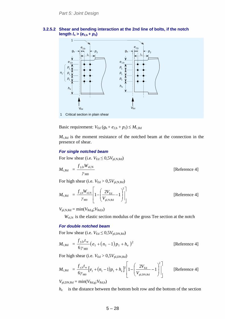
Part 5: Joint Design
5 – 28
3.2.5.2 Shear and bending interaction at the 2nd line of bolts, if the notch length ln > (e2,b + p2)
e egh 2
p
p
p
1
1
1
he
VEd
p
p
p
1
1
1
he
gh 2
VEd
p2,b 2,b
n
e
pn
e
l l
1,b 1,b
n1
1
1 Critical section in plain shear
Basic requirement: VEd (gh + e2,b + p2) Mc,Rd
Mc,Rd is the moment resistance of the notched beam at the connection in the presence of shear.
For single notched beam
For low shear (i.e. VEd ≤ 0,5Vpl,N,Rd)
Mc,Rd = M0
Nel,by,
Wf
[Reference 4]
For high shear (i.e. VEd > 0,5Vpl,N,Rd)
Mc,Rd =
2
RdN,pl,
Ed
M0
Nel,by, 12
1V
VWf
[Reference 4]
Vpl,N,Rd = min(VRd,g;VRd,b)
Wel,N is the elastic section modulus of the gross Tee section at the notch
For double notched beam
For low shear (i.e. VEd ≤ 0,5Vpl,DN,Rd)
Mc,Rd = 2e111
M0
wby,1
6hpne
tf
[Reference 4]
For high shear (i.e. VEd > 0,5Vpl,DN,Rd)
Mc,Rd =
2
RdDN,pl,
Ed2e111
M0
wby, 12
116 V
Vhpne
tf
[Reference 4]
Vpl,DN,Rd = min(VRd,g;VRd,b)
he is the distance between the bottom bolt row and the bottom of the section
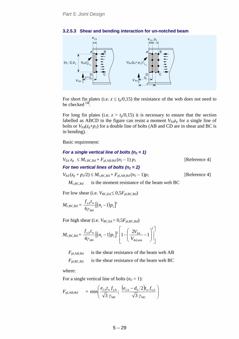
Part 5: Joint Design
5 – 29
3.2.5.3 Shear and bending interaction for un-notched beam
B B
C CD D
A A
ee
1
V Ed
2
V Ed
p
2,b2,b p
2
zz
Edz( -1) 1n ( + )z pV VEdp
p p
p
z=
z
For short fin plates (i.e. z ≤ tp/0,15) the resistance of the web does not need to be checked [4].
For long fin plates (i.e. z > tp/0,15) it is necessary to ensure that the section labelled as ABCD in the figure can resist a moment VEdzp for a single line of bolts or VEd(zp+p2) for a double line of bolts (AB and CD are in shear and BC is in bending).
Basic requirement:
For a single vertical line of bolts (n2 = 1)
VEd zp Mc,BC,Rd + Fpl,AB,Rd (n1 – 1) p1 [Reference 4]
For two vertical lines of bolts (n2 = 2)
VEd (zp + p2/2) Mc,BC,Rd + Fpl,AB,Rd (n1 – 1)p1 [Reference 4]
Mc,BC,Rd is the moment resistance of the beam web BC
For low shear (i.e. VBC,Ed ≤ 0,5Fpl,BC,Rd)
Mc,BC,Rd = 211M0
wby, 16
pntf
For high shear (i.e. VBC,Ed > 0,5Fpl,BC,Rd)
Mc,BC,Rd = 211M0
wby, 14
pntf
2
minRd,
Ed 1
21
V
V
Fpl,AB,Rd is the shear resistance of the beam web AB
Fpl,BC,Rd is the shear resistance of the beam web BC
where:
For a single vertical line of bolts (n2 = 1):
Fpl,AB,Rd =
M2
bu,w0b2,
M0
by,wb2,
3
2;
3min
ftdefte
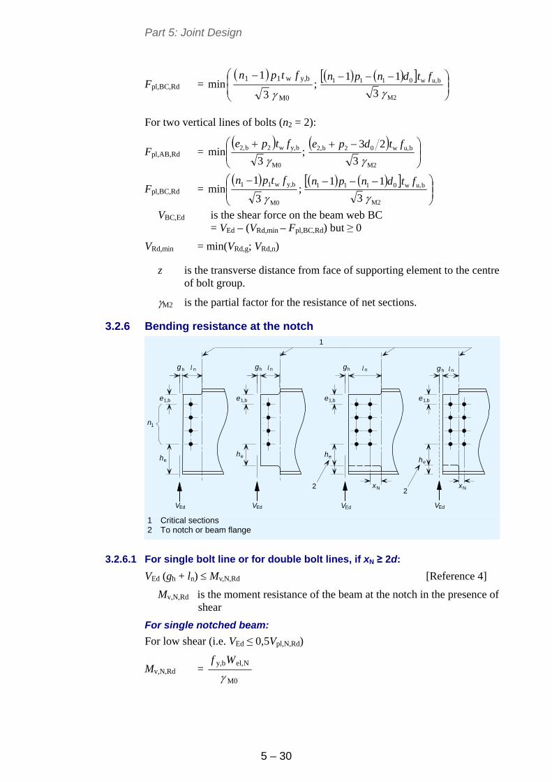
Part 5: Joint Design
5 – 30
Fpl,BC,Rd =
;
3
1min
M0
by,w11
ftpn
M2
bu,w0111
3
11
ftdnpn
For two vertical lines of bolts (n2 = 2):
Fpl,AB,Rd =
;
3min
M0
by,w2b2,
ftpe
M2
bu,w02b2,
3
23
ftdpe
Fpl,BC,Rd =
;
3
1min
M0
by,w11
ftpn
M2
bu,w0111
3
11
ftdnpn
VBC,Ed is the shear force on the beam web BC = VEd – (VRd,min – Fpl,BC,Rd) but ≥ 0
VRd,min = min(VRd,g; VRd,n)
z is the transverse distance from face of supporting element to the centre of bolt group.
M2 is the partial factor for the resistance of net sections.
3.2.6 Bending resistance at the notch
N Nx x
g h n
he
VEd VEd
he
gh n gh n
he
VEd
gh n
he
VEd
e e e e
llll
1,b 1,b 1,b 1,b
n1
1
22
1 Critical sections 2 To notch or beam flange
3.2.6.1 For single bolt line or for double bolt lines, if xN ≥ 2d:
VEd (gh + ln) Mv,N,Rd [Reference 4]
Mv,N,Rd is the moment resistance of the beam at the notch in the presence of shear
For single notched beam:
For low shear (i.e. VEd ≤ 0,5Vpl,N,Rd)
Mv,N,Rd = M0
Nel,by,
Wf
Part 5: Joint Design
5 – 31
For high shear (i.e. VEd > 0,5Vpl,N,Rd)
Mv,N,Rd =
2
RdN,pl,
Ed
M0
Nel,by, 1
21
V
VWf
For double notched beam:
For low shear (i.e. VEd ≤ 0,5Vpl,DN,Rd)
Mv,DN,Rd = 2e11b1,
M0
wby,)1(
6hpne
tf
For high shear (i.e. VEd > 0,5Vpl,DN,Rd)
Mv,DN,Rd =
2
RdDN,pl,
Ed2e11b1,
M0
wby, 1
211
4 V
Vhpne
tf
3.2.6.2 For double bolt lines, if xN < 2d:
max (VEd (gh + ln); VEd (gh + e2,b + p2)) ≤ Mv,N,Rd [Reference 4]
Mv,N,Rd = Mc,Rd from the previous check
where:
Wel,N is the elastic section modulus of the gross tee section at the notch
Vpl,N,Rd is the shear resistance at the notch for single notched beams
= M0
by,Nv,
3
fA
Av,N = ATee – btf + (tw + 2r)2ft
Vpl,DN,Rd is the shear resistance at the notch for double notched beams
= M0
by,DNv,
3
fA
Av,DN = tw (e1,b + (n1 –1) p1 + he)
he is the distance between the bottom bolt row and the bottom of the section
ATee is the area of the Tee section
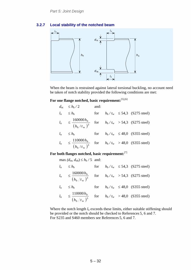
Part 5: Joint Design
5 – 32
3.2.7 Local stability of the notched beam
d
d
n n
h
n
h
nt
nb
l l
l
b b
When the beam is restrained against lateral torsional buckling, no account need be taken of notch stability provided the following conditions are met:
For one flange notched, basic requirement:[5],[6]
dnt hb / 2 and:
ln hb for hb / tw 54,3 (S275 steel)
ln 3
wb
b
/
160000
th
h for hb / tw > 54,3 (S275 steel)
ln hb for hb / tw 48,0 (S355 steel)
ln 3
wb
b
/
110000
th
h for hb / tw > 48,0 (S355 steel)
For both flanges notched, basic requirement:[7]
max (dnt, dnb) hb / 5 and:
ln hb for hb / tw 54,3 (S275 steel)
ln 3
wb
b160000
th
h for hb / tw > 54,3 (S275 steel)
ln hb for hb / tw 48,0 (S355 steel)
ln 3
wb
b110000
th
h for hb / tw > 48,0 (S355 steel)
Where the notch length ln exceeds these limits, either suitable stiffening should be provided or the notch should be checked to References 5, 6 and 7. For S235 and S460 members see References 5, 6 and 7.
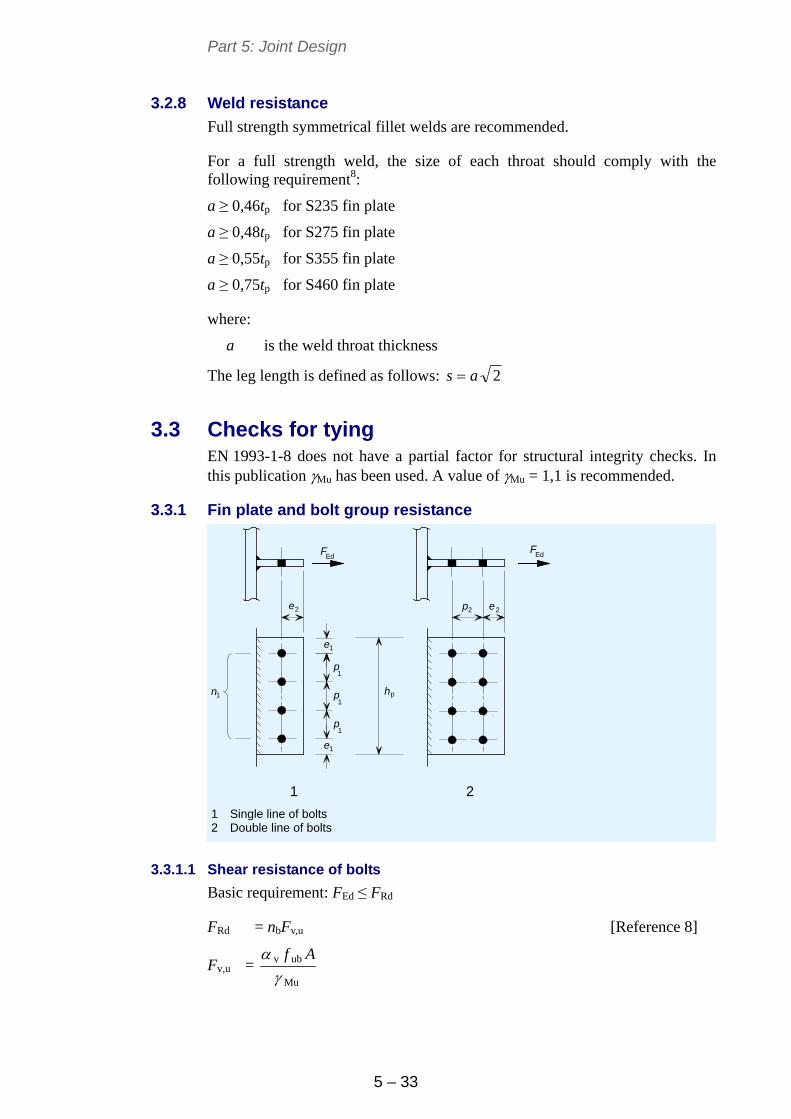
Part 5: Joint Design
5 – 33
3.2.8 Weld resistance
Full strength symmetrical fillet welds are recommended.
For a full strength weld, the size of each throat should comply with the following requirement8:
a ≥ 0,46tp for S235 fin plate
a ≥ 0,48tp for S275 fin plate
a ≥ 0,55tp for S355 fin plate
a ≥ 0,75tp for S460 fin plate
where:
a is the weld throat thickness
The leg length is defined as follows: 2as
3.3 Checks for tying EN 1993-1-8 does not have a partial factor for structural integrity checks. In this publication Mu has been used. A value of Mu = 1,1 is recommended.
3.3.1 Fin plate and bolt group resistance
1
1
e
2 2e e
e
1
1
1
hp
2
p
p
p
FEd
FEd
n1
p
1 2 1 Single line of bolts 2 Double line of bolts
3.3.1.1 Shear resistance of bolts
Basic requirement: FEd ≤ FRd
FRd = nbFv,u [Reference 8]
Fv,u = Mu
ubv
Af
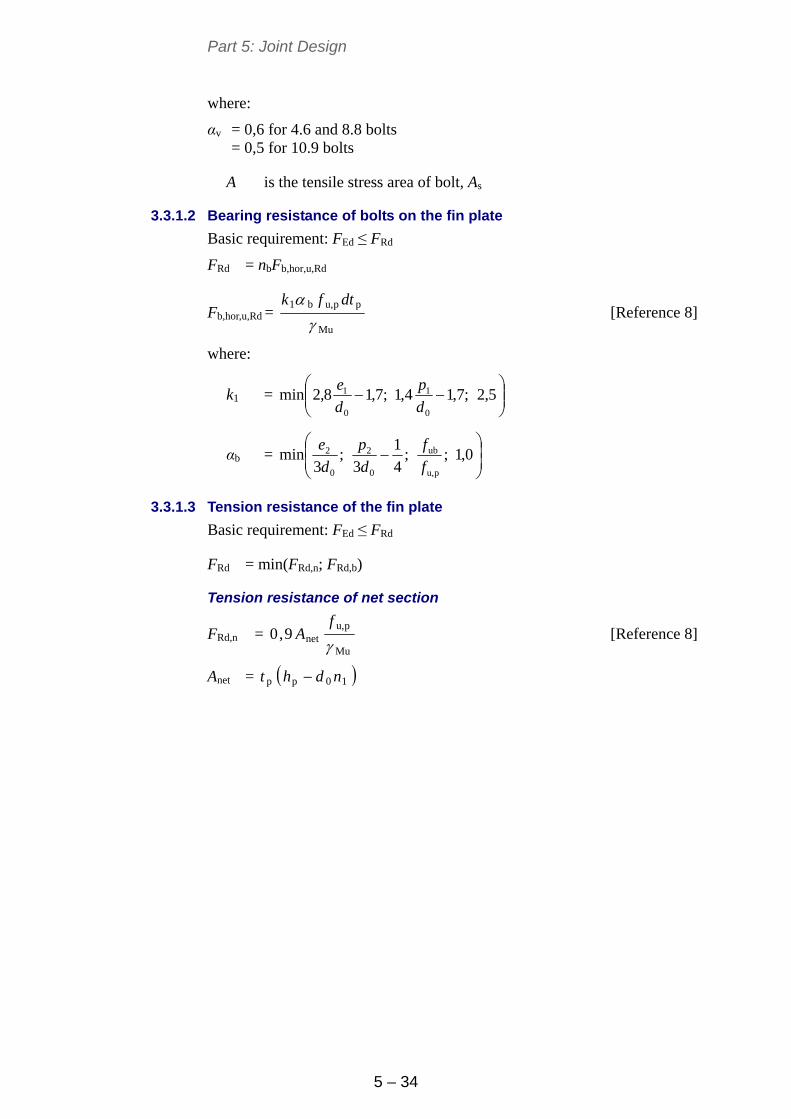
Part 5: Joint Design
5 – 34
where:
αv = 0,6 for 4.6 and 8.8 bolts = 0,5 for 10.9 bolts
A is the tensile stress area of bolt, As
3.3.1.2 Bearing resistance of bolts on the fin plate
Basic requirement: FEd ≤ FRd
FRd = nbFb,hor,u,Rd
Fb,hor,u,Rd = Mu
ppu,b1
dtfk
[Reference 8]
where:
k1 =
5,2;7,14,1;7,18,2min
0
1
0
1
d
p
d
e
αb =
0,1;;
4
1
3;
3min
pu,
ub
0
2
0
2
f
f
d
p
d
e
3.3.1.3 Tension resistance of the fin plate
Basic requirement: FEd ≤ FRd
FRd = min(FRd,n; FRd,b)
Tension resistance of net section
FRd,n = Mu
pu,net9,0
f
A [Reference 8]
Anet = 10pp ndht
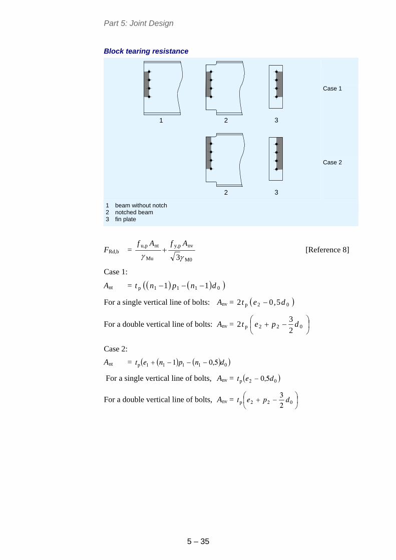
Part 5: Joint Design
5 – 35
Block tearing resistance
Case 1
1 32
32
Case 2
1 beam without notch 2 notched beam 3 fin plate
FRd,b = M0
nvpy,
Mu
ntpu,
3AfAf
[Reference 8]
Case 1:
Ant = 0111p 11 dnpnt
For a single vertical line of bolts: Anv = 02p 5,02 det
For a double vertical line of bolts: Anv =
022p
2
32 dpet
Case 2:
Ant = 01111p 5,01 dnpnet
For a single vertical line of bolts, Anv = 02p 5,0 det
For a double vertical line of bolts, Anv =
022p 2
3dpet
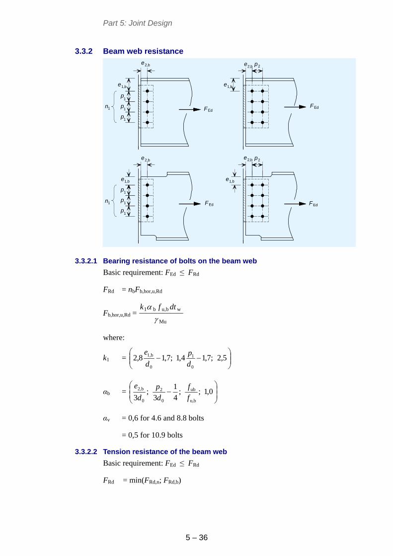
Part 5: Joint Design
5 – 36
3.3.2 Beam web resistance
e e
e e
ee
2
2
1
1
1
1
1
1
e
p
p
p
p
p
p
p
p2,b
FEd
FEdFEd
FEd
2,b
2,b e2,b
1,b 1,b
1,b 1,b
n1
n1
3.3.2.1 Bearing resistance of bolts on the beam web
Basic requirement: FEd ≤ FRd
FRd = nbFb,hor,u,Rd
Fb,hor,u,Rd = Mu
wbu,b1
dtfk
where:
k1 =
5,2;7,14,1;7,18,2
0
1
0
b1,
d
p
d
e
αb =
0,1;;
4
1
3;
3 bu,
ub
0
2
0
b2,
f
f
d
p
d
e
αv = 0,6 for 4.6 and 8.8 bolts
= 0,5 for 10.9 bolts
3.3.2.2 Tension resistance of the beam web
Basic requirement: FEd ≤ FRd
FRd = min(FRd,n; FRd,b)
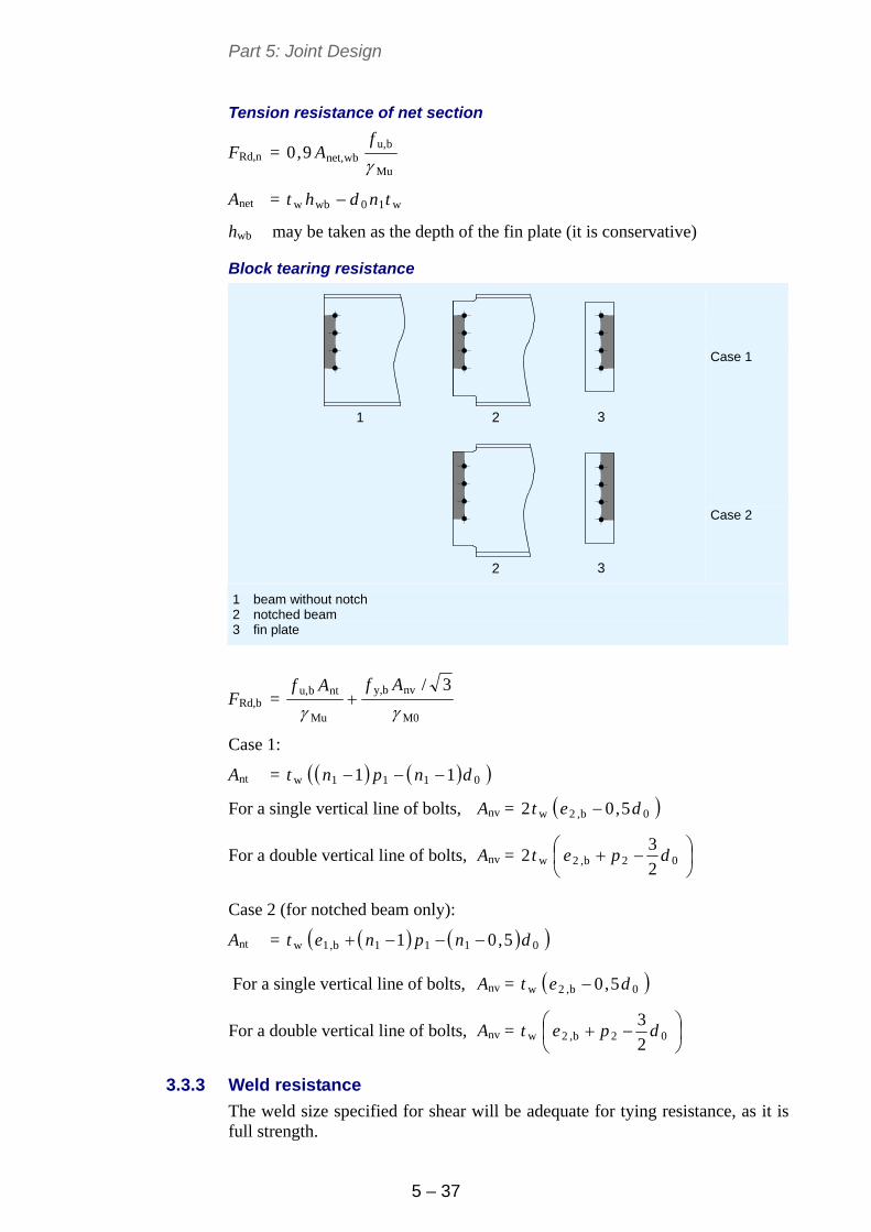
Part 5: Joint Design
5 – 37
Tension resistance of net section
FRd,n = Mu
bu,wbnet,9,0
f
A
Anet = w10wbw tndht
hwb may be taken as the depth of the fin plate (it is conservative)
Block tearing resistance
Case 1
1 32
32
Case 2
1 beam without notch 2 notched beam 3 fin plate
FRd,b = M0
nvby,
Mu
ntbu, 3/
AfAf
Case 1:
Ant = 0111w 11 dnpnt
For a single vertical line of bolts, Anv = 0b,2w 5,02 det
For a double vertical line of bolts, Anv =
02b,2w
2
32 dpet
Case 2 (for notched beam only):
Ant = 0111b,1w 5,01 dnpnet
For a single vertical line of bolts, Anv = 0b,2w 5,0 det
For a double vertical line of bolts, Anv =
02b,2w
2
3dpet
3.3.3 Weld resistance
The weld size specified for shear will be adequate for tying resistance, as it is full strength.
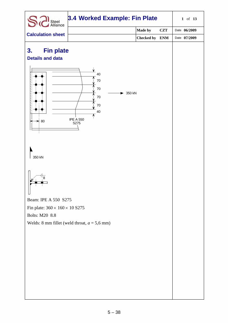
5 – 38
3.4 Worked Example: Fin Plate 1 of 13
Made by CZT Date 06/2009
Calculation sheet Checked by ENM Date 07/2009
3. Fin plate
Details and data
70
70
70
70
40
40
80
350 kN
350 kN
8
IPE A 550S275
Beam: IPE A 550 S275
Fin plate: 360 160 10 S275
Bolts: M20 8.8
Welds: 8 mm fillet (weld throat, a = 5,6 mm)
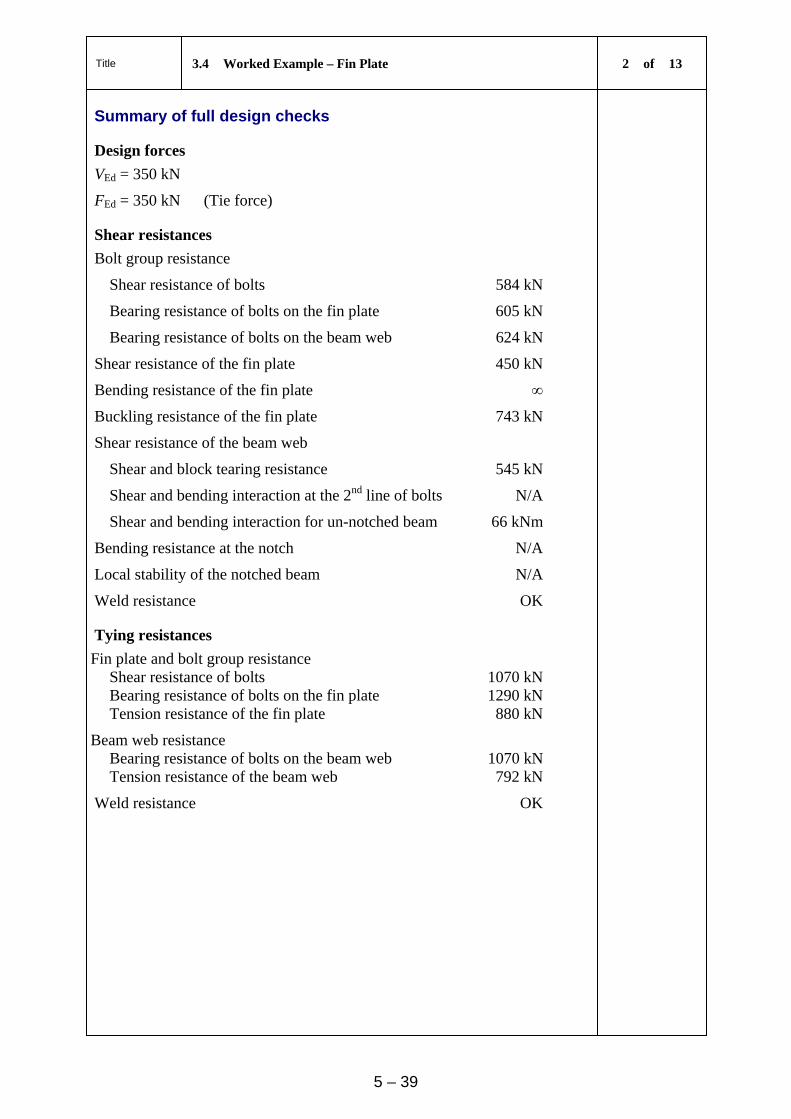
Title 3.4 Worked Example – Fin Plate 2 of 13
5 – 39
Summary of full design checks
Design forces
VEd = 350 kN
FEd = 350 kN (Tie force)
Shear resistances
Bolt group resistance
Shear resistance of bolts 584 kN
Bearing resistance of bolts on the fin plate 605 kN
Bearing resistance of bolts on the beam web 624 kN
Shear resistance of the fin plate 450 kN
Bending resistance of the fin plate ∞
Buckling resistance of the fin plate 743 kN
Shear resistance of the beam web
Shear and block tearing resistance 545 kN
Shear and bending interaction at the 2nd line of bolts N/A
Shear and bending interaction for un-notched beam 66 kNm
Bending resistance at the notch N/A
Local stability of the notched beam N/A
Weld resistance OK
Tying resistances
Fin plate and bolt group resistance Shear resistance of bolts 1070 kN Bearing resistance of bolts on the fin plate 1290 kN Tension resistance of the fin plate 880 kN
Beam web resistance Bearing resistance of bolts on the beam web 1070 kN Tension resistance of the beam web 792 kN
Weld resistance OK
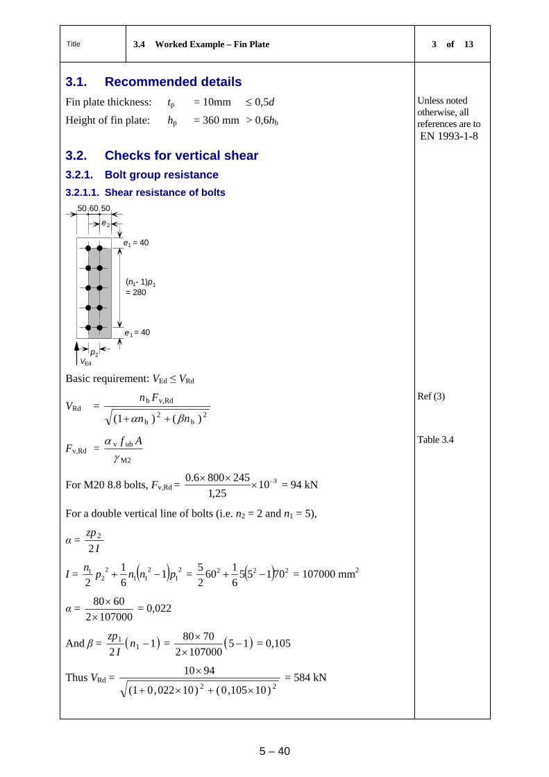
Title 3.4 Worked Example – Fin Plate 3 of 13
5 – 40
3.1. Recommended details
Fin plate thickness: tp = 10mm 0,5d
Height of fin plate: hp = 360 mm > 0,6hb
Unless noted otherwise, all references are to EN 1993-1-8
3.2. Checks for vertical shear
3.2.1. Bolt group resistance
3.2.1.1. Shear resistance of bolts
e
e
1
11
1
50 50
2e
= 40
= 40
60
VEd
p
p2
(n= 280
- 1)
Basic requirement: VEd ≤ VRd
VRd = 2
b2
b
Rdv,b
)()(1 nn
Fn
Ref (3)
Fv,Rd = M2
ubv
Af
Table 3.4
For M20 8.8 bolts, Fv,Rd = 31025,1
2458006.0
= 94 kN
For a double vertical line of bolts (i.e. n2 = 2 and n1 = 5),
α = I
zp
22
I = 21
211
22
1 16
1
2pnnp
n = 222 70155
6
160
2
5 = 107000 mm2
α = 1070002
6080
= 0,022
And β = 12
11 nI
zp = 15
1070002
7080
= 0,105
Thus VRd = 22 )10105,0()10022,0(1
9410
= 584 kN
Title 3.4 Worked Example – Fin Plate 4 of 13
5 – 41
VEd = 350 kN ≤ 584 kN, OK
3.2.1.2. Bearing resistance of bolts on the fin plate
Basic requirement: VEd ≤ VRd
VRd = 2
Rdhor,b,
b
2
Rdver,b,
b
b
1
F
n
F
n
n
Ref [3]
α = 0,022 and β = 0,105, as above
The vertical bearing resistance of a single bolt, Fb,ver,Rd = M2
ppu,b1
dtfk
Table 3.4
k1 =
5,2;7,14,1;7,18,2min
0
2
0
2
d
p
d
e
=
5,2;7,1
22
604,1;7,1
22
508,2min = min( 4,67; 2,12; 2,5) = 2,12
αb =
0,1;;
4
1
3;
3min
pu,
ub
0
1
0
1
f
f
d
p
d
e=
0,1;
430
800;
4
1
223
70;
223
40min
= min( 0,61; 0,81; 1,86; 1,0) = 0,61
Fb,ver,Rd = 31025,1
102043061,012,2
= 89 kN
The horizontal bearing resistance of a single bolt, Fb,hor,Rd = M2
ppu,b1
dtfk
Table 3.4
k1 =
5,2;7,14,1;7,18,2min
0
1
0
1
d
p
d
e
=
5,2;7,1
22
704,1;7,1
22
408,2min = min( 3,39; 2,75; 2,5) = 2,5
αb =
0,1;;25,0
3;
3min
pu,
ub
0
2
0
2
f
f
d
p
d
e
=
0,1;
430
800;25,0
223
60;
223
50min = min( 0,75; 0,66; 1,0) = 0,66
Fb,hor,Rd = 31025,1
102043066,05,2
= 114 kN
VRd = 22
114
10105,0
89
10022,01
10
= 605 kN
Title 3.4 Worked Example – Fin Plate 5 of 13
5 – 42
VEd = 350 kN ≤ 605 kN, OK
3.2.1.3. Bearing resistance of bolts on the beam web
Basic requirement: VEd ≤ VRd
VRd = 2
Rdhor,b,
b
2
Rdver,b,
b
b
1
F
n
F
n
n
Ref (3]
α = 0,022 and β = 0,105, as above
The vertical bearing resistance for a single bolt, Fb,ver,Rd = M2
wbu,b1
dtfk
Table 3.4
k1 =
5,2;7,14,1;7,18,2min
0
2
0
2
d
p
d
e
=
5,2;7,1
22
604,1;7,1
22
408,2min = min( 3,39; 2,12; 2,5) = 2,12
αb =
0,1;;
4
1
3min
bu,
ub
0
1
f
f
d
p=
0,1;
430
800;
4
1
223
70min
= min( 0,81; 1,86; 1,0) = 0,81
Fb,ver,Rd = 31025,1
92043081,012,2
= 106 kN
The horizontal bearing resistance for a single bolt, Fb,hor,Rd = M2
wbu,b1
dtfk
Table 3.4
k1 =
5,2;7,14,1min
0
1
d
p=
5,2;7,1
22
704,1min
= min( 2,75; 2,5) = 2,5
αb =
0,1;;
4
1
3;
3min
bu,
ub
0
2
0
b2,
f
f
d
p
d
e=
0,1;
430
800;
4
1
223
60;
223
40min
= min( 0,61; 0,81; 1,86; 1,0) = 0,61
Fb,hor,Rd = 31025,1
92043061,05,2
= 94 kN
VRd = 22
94
10105,0
106
10022,01
10
= 624 kN
VEd = 350 kN ≤ 624 kN, OK
Title 3.4 Worked Example – Fin Plate 6 of 13
5 – 43
3.2.2. Shear resistance of the fin plate
e
e
1
11
1
50 50
2e
= 40
= 40
60
VEd
p
p2
(n= 280
- 1)
Basic requirement: VEd ≤ VRd,min
VRd,min = min(VRd,g; VRd,n; VRd,b)
3.2.2.1. Shear resistance of gross section
VRd,g = M0
py,pp
327,1
fth = 310
0,1327,1
27510360
= 450 kN
Ref (8)
3.2.2.2. Shear resistance of net section
VRd,n = M2
pu,netv,
3
fA
Ref [8]
Net area, Av,net = 0pp ndht = 22536010 = 2500 mm2
VRd = 31025,13
4302500
= 497 kN
3.2.2.3. Block tearing resistance
VRd,b = 3
M0
nvpy,
M2
ntpu,10
3
5,0
AfAf
Ref [8]
Net area subject to tension, Ant = 022p 5,1 dept
= 770225,1506010 mm2
Net area subject to shear, Ant = 011pp )5,0( dneht
= 221022)5,05(4036010 mm2
VRd,b = 0,13
2210275
25,1
7704305,0
= 483 kN
VRd,min = min(450; 497; 483) = 450 kN
VEd = 350 kN ≤ 450 kN, OK
Title 3.4 Worked Example – Fin Plate 7 of 13
5 – 44
3.2.3. Bending resistance of the fin plate
Basic requirement: VEd ≤ VRd Ref [8]
2,73 z = 2,73 80 = 218 mm
hp = 360 mm > 218 mm
Then RdV
RdEd VV , OK
3.2.4. Buckling resistance of the fin plate
Basic requirement: VEd ≤ VRd
tp/0,15 = 15,0
10 = 67 mm
Ref [8]
z = 80 mm > 67 mm
VRd =
M0
py,pel,
M1
LTp,pel, ;6,0
minf
z
Wf
z
W
fp,LT from BS5950-1 Table 17 (See Appendix A)
Wel,p =6
2ppht
2160006
36010 2
mm3
zp = 80 mm
λLT =
2/1
2p
pp
5,18,2
t
hz=
2/1
2105,1
360508,2
= 31
fp,LT is obtained by interpolation from Appendix A.
fp,LT = 274 N/mm2
VRd =
33 10
0,1
275
80
216000;10
0,16,0
274
80
216000min
= 743;1233min = 743 kN
VEd = 350 kN ≤ 743 kN, OK
3.2.5. Shear resistance of the beam web
3.2.5.1. Shear and block tearing resistance
Basic requirement: VEd ≤ VRd,min
VRd,min = min(VRd,g; VRd,n; VRd,b)
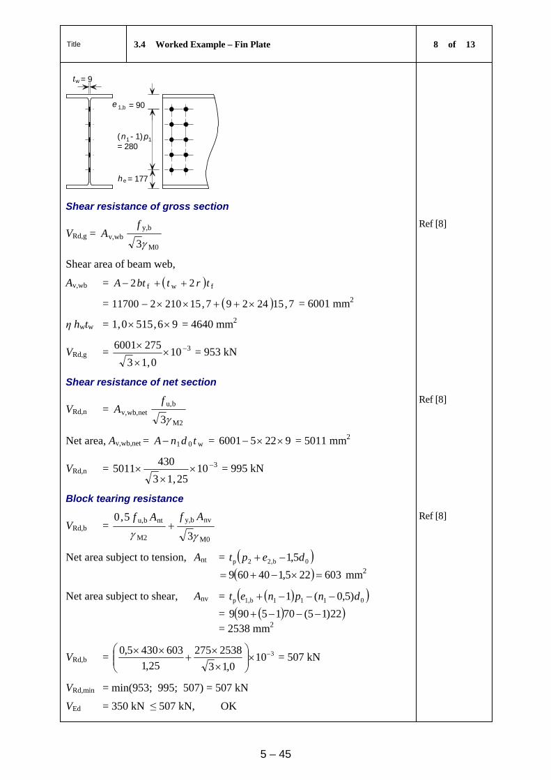
Title 3.4 Worked Example – Fin Plate 8 of 13
5 – 45
t w
e
he = 177
= 90
= 9
(n1 1- 1)p= 280
1,b
Shear resistance of gross section
VRd,g = M0
by,wbv,
3
fA
Ref [8]
Shear area of beam web,
Av,wb = fwf 22 trtbtA
= 7,1524297,15210211700 = 6001 mm2
η hwtw = 96,5150,1 = 4640 mm2
VRd,g = 3100,13
2756001
= 953 kN
Shear resistance of net section
VRd,n = M2
bu,netwb,v,
3
fA
Ref [8]
Net area, Av,wb,net = w01 tdnA = 92256001 = 5011 mm2
VRd,n = 31025,13
4305011
= 995 kN
Block tearing resistance
VRd,b = M0
nvby,
M2
ntbu,
3
5,0
AfAf
Ref [8]
Net area subject to tension, Ant = 0b,22p 5,1 dept
603225,140609 mm2
Net area subject to shear, Anv = 0111b1,p )5,0(1 dnpnet
= 22)15(7015909 = 2538 mm2
VRd,b = 3100,13
2538275
25,1
6034305,0
= 507 kN
VRd,min = min(953; 995; 507) = 507 kN
VEd = 350 kN ≤ 507 kN, OK
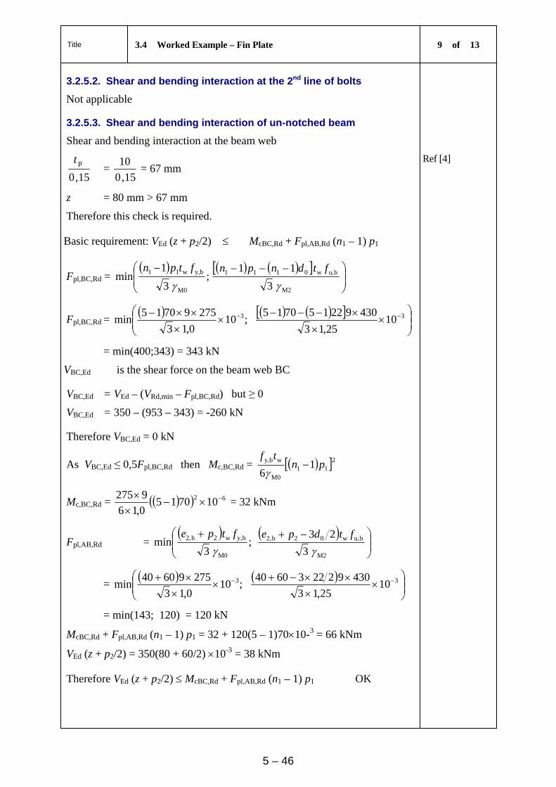
Title 3.4 Worked Example – Fin Plate 9 of 13
5 – 46
3.2.5.2. Shear and bending interaction at the 2nd line of bolts
Not applicable
3.2.5.3. Shear and bending interaction of un-notched beam
Shear and bending interaction at the beam web
15,0
pt =
15,0
10 = 67 mm
Ref [4]
z = 80 mm > 67 mm
Therefore this check is required.
Basic requirement: VEd (z + p2/2) McBC,Rd + Fpl,AB,Rd (n1 – 1) p1
Fpl,BC,Rd =
;
3
1min
M0
by,w11
ftpn
M2
bu,w0111
3
11
ftdnpn
Fpl,BC,Rd =
;100,13
27597015min 3
310
25,13
430922157015
= min(400;343) = 343 kN
VBC,Ed is the shear force on the beam web BC
VBC,Ed = VEd – (VRd,min – Fpl,BC,Rd) but ≥ 0
VBC,Ed = 350 – (953 – 343) = -260 kN
Therefore VBC,Ed = 0 kN
As VBC,Ed ≤ 0,5Fpl,BC,Rd then Mc,BC,Rd = 211M0
wby, 16
pntf
Mc,BC,Rd = 62 1070150,16
9275
= 32 kNm
Fpl,AB,Rd =
;
3min
M0
by,w2b2,
ftpe
M2
bu,w02b2,
3
23
ftdpe
=
;100,13
27596040min 3
310
25,13
430922236040
= min(143; 120) = 120 kN
McBC,Rd + Fpl,AB,Rd (n1 – 1) p1 = 32 + 120(5 – 1)7010-3 = 66 kNm
VEd (z + p2/2) = 350(80 + 60/2) 10-3 = 38 kNm
Therefore VEd (z + p2/2) McBC,Rd + Fpl,AB,Rd (n1 – 1) p1 OK
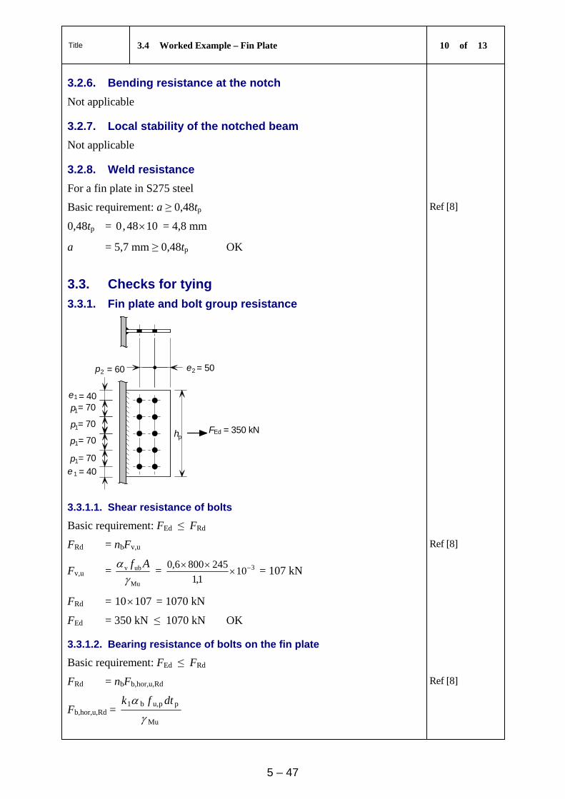
Title 3.4 Worked Example – Fin Plate 10 of 13
5 – 47
3.2.6. Bending resistance at the notch
Not applicable
3.2.7. Local stability of the notched beam
Not applicable
3.2.8. Weld resistance
For a fin plate in S275 steel
Basic requirement: a ≥ 0,48tp Ref [8]
0,48tp = 1048,0 = 4,8 mm
a = 5,7 mm ≥ 0,48tp OK
3.3. Checks for tying
3.3.1. Fin plate and bolt group resistance
p
p
p
p
e 1
1
2e
h
= 50
= 40
= 40= 70
= 70
= 70
= 70
e
p 2
1
1
1
1
pEdF
= 60
= 350 kN
3.3.1.1. Shear resistance of bolts
Basic requirement: FEd ≤ FRd
FRd = nbFv,u Ref [8]
Fv,u = Mu
ubv
Af
= 3101,1
2458006,0
= 107 kN
FRd = 10710 = 1070 kN
FEd = 350 kN ≤ 1070 kN OK
3.3.1.2. Bearing resistance of bolts on the fin plate
Basic requirement: FEd ≤ FRd
FRd = nbFb,hor,u,Rd Ref [8]
Fb,hor,u,Rd = Mu
ppu,b1
dtfk
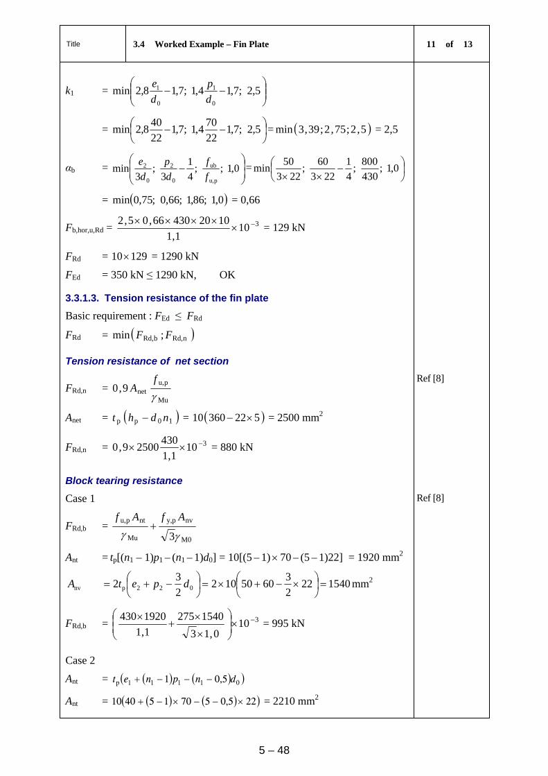
Title 3.4 Worked Example – Fin Plate 11 of 13
5 – 48
k1 =
5,2;7,14,1;7,18,2min
0
1
0
1
d
p
d
e
=
5,2;7,1
22
704,1;7,1
22
408,2min = 5,2;75,2;39,3min = 2,5
αb =
0,1;;
4
1
3;
3min
pu,
ub
0
2
0
2
f
f
d
p
d
e=
0,1;
430
800;
4
1
223
60;
223
50min
= 0,1;86,1;66,0;75,0min = 0,66
Fb,hor,u,Rd = 3101,1
102043066,05,2
= 129 kN
FRd = 12910 = 1290 kN
FEd = 350 kN ≤ 1290 kN, OK
3.3.1.3. Tension resistance of the fin plate
Basic requirement : FEd ≤ FRd
FRd = nRd,bRd, ;min FF
Tension resistance of net section
FRd,n = Mu
pu,net9,0
f
A Ref [8]
Anet = 10pp ndht = 52236010 = 2500 mm2
FRd,n = 3101,1
43025009,0 = 880 kN
Block tearing resistance
Case 1
FRd,b = M0
nvpy,
Mu
ntpu,
3AfAf
Ref [8]
Ant = tp[(n1 – 1)p1 – (n1 – 1)d0] = 10[(5 – 1) 70 – (5 – 1)22] = 1920 mm2
1540222
36050102
2
32 022pnv
dpetA mm2
FRd,b = 3100,13
1540275
1,1
1920430
= 995 kN
Case 2
Ant = 01111p 5,01 dnpnet
Ant = 225,0570154010 = 2210 mm2
Title 3.4 Worked Example – Fin Plate 12 of 13
5 – 49
Anv =
022p 2
3dpet =
22
23
605010 = 770 mm2
FRd,b = 3100,13
7702751,12210430
= 986 kN
FRd = 986;995;880min = 880 kN
FEd = 350 kN ≤ 880 kN, OK
3.3.2. Beam web resistance
e
2
1
e
=70
=90
=40
=60p
pFEd
1,b
2,b
3.3.2.1. Bearing resistance of bolts on the beam web
Basic requirement: FEd ≤ FRd
FRd = nbFb,hor,u,Rd
Fb,hor,u,Rd = Mu
wbu,b1
dtfk
k1 =
5,2;7,14,1;7,18,2min
0
1
0
b1,
d
p
d
e
=
5,2;7,1
22
704,1;7,1
22
908,2min = 5,2;75,2;8,9min = 2,5
αb =
0,1;;
4
1
3;
3min
bu,
ub
0
2
0
b2,
f
f
d
p
d
e=
0,1;
430
800;
4
1
223
60;
223
40min
= 0,1;86,1;66,0;61,0min = 0,61
Fb,hor,u,Rd = 3101,1
92043061,05,2
= 107 kN
FRd = 10710 = 1070 kN
FEd = 350 kN ≤ 1070 kN OK
Title 3.4 Worked Example – Fin Plate 13 of 13
5 – 50
3.3.2.2. Tension resistance of the beam web
Basic requirement : FEd ≤ FRd
FRd = nRd,bRd, ;min FF
Tension resistance of net section
FRd,n = Mu
bu,wbnet,9,0
f
A
Anet,wb = w10wbw tndht = 95223609 = 2250 mm2
FRd,n = 3101,1
43022509,0 = 792 kN
Block tearing resistance
FRd,b = M0
nvby,
Mu
ntbu, 3/
AfAf
0111wnt 11 dnpntA
= 1728221570159 mm2
1206222
3604092
2
32 02b,2wnv
dpetA mm2
FRd,b = 3100,13
1206275
1,1
1728430
= 867 kN
(Case 2 only applies to notched beams)
FRd = 867;792min = 792 kN
FEd = 350 kN ≤ 792 kN, OK
3.3.3. Weld resistance
The weld size specified for shear will be adequate for tying resistance, as it is full strength.
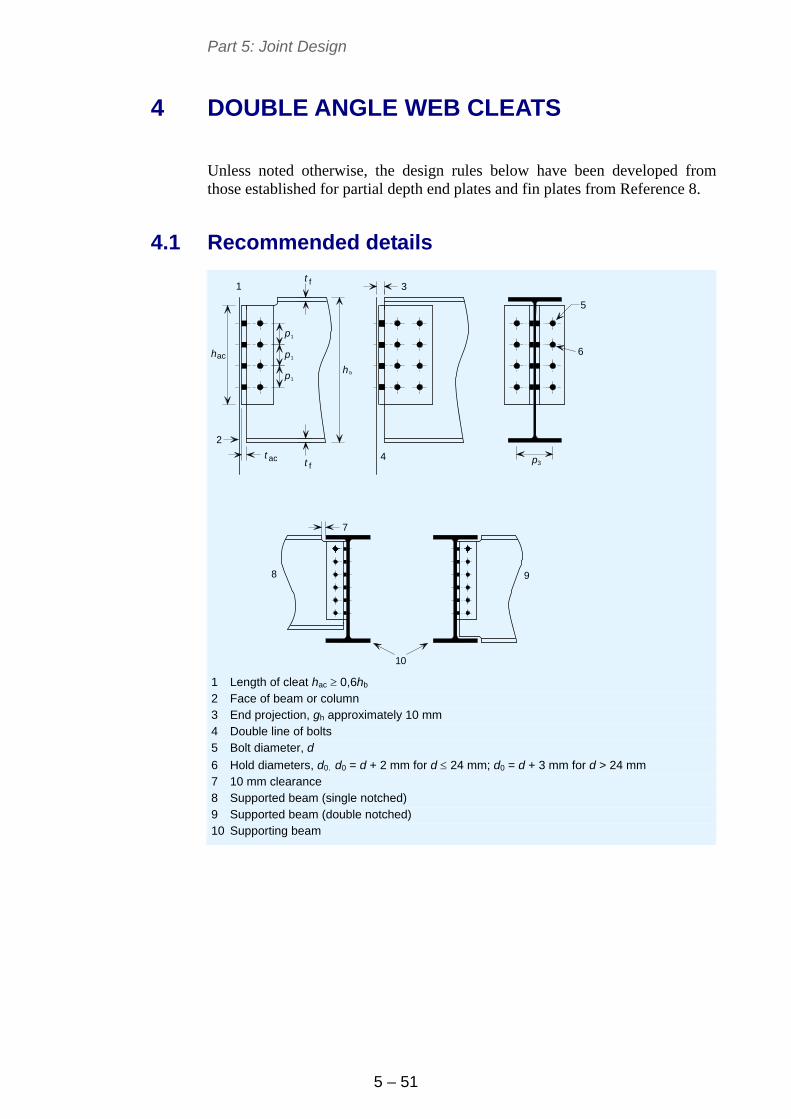
Part 5: Joint Design
5 – 51
4 DOUBLE ANGLE WEB CLEATS
Unless noted otherwise, the design rules below have been developed from those established for partial depth end plates and fin plates from Reference 8.
4.1 Recommended details
p
p
p
1
1
1
3 t
t f
ft pac
ach
h b
1 3
5
6
4
2
9
10
7
8
1 Length of cleat hac 0,6hb 2 Face of beam or column 3 End projection, gh approximately 10 mm 4 Double line of bolts 5 Bolt diameter, d
6 Hold diameters, d0. d0 = d + 2 mm for d 24 mm; d0 = d + 3 mm for d > 24 mm 7 10 mm clearance 8 Supported beam (single notched) 9 Supported beam (double notched) 10 Supporting beam
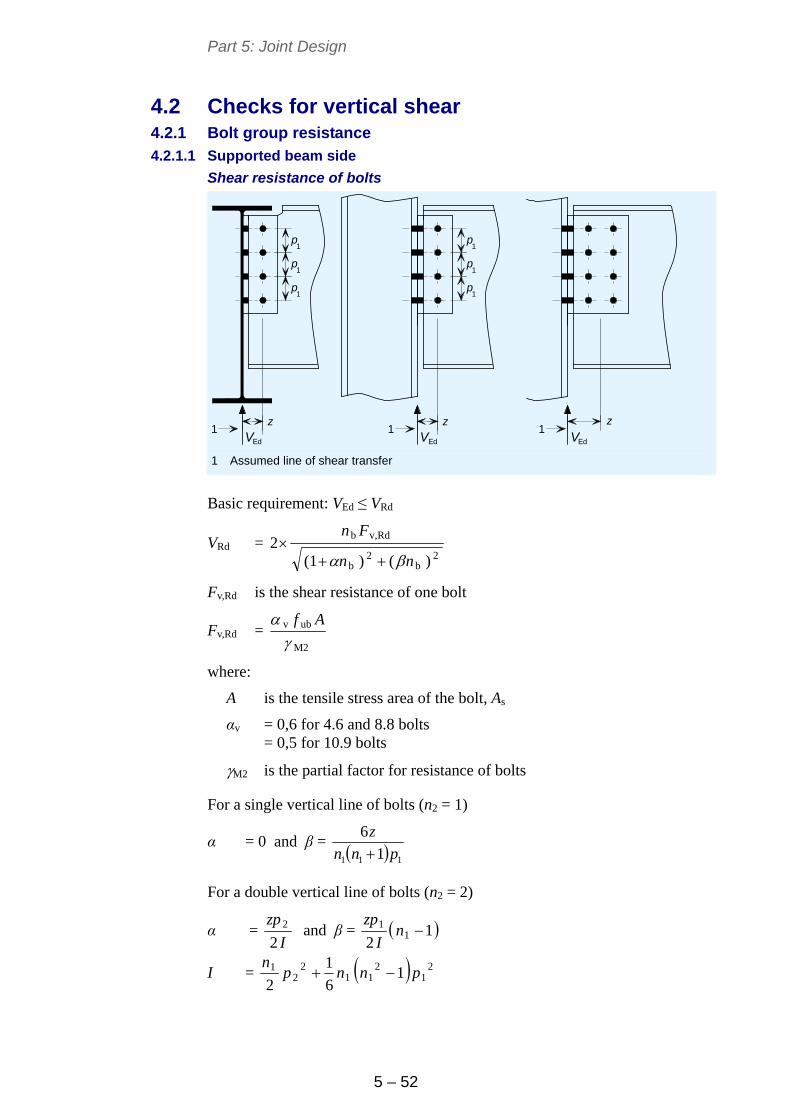
Part 5: Joint Design
5 – 52
4.2 Checks for vertical shear 4.2.1 Bolt group resistance
4.2.1.1 Supported beam side
Shear resistance of bolts
p p
p p
p p
zz
1 1
1 1
1 1
Ed Ed EdV V Vz
1 1 1
1 Assumed line of shear transfer
Basic requirement: VEd ≤ VRd
VRd = 2
b2
b
Rdv,b
)()(12
nn
Fn
Fv,Rd is the shear resistance of one bolt
Fv,Rd = M2
ubv
Af
where:
A is the tensile stress area of the bolt, As
αv = 0,6 for 4.6 and 8.8 bolts = 0,5 for 10.9 bolts
M2 is the partial factor for resistance of bolts
For a single vertical line of bolts (n2 = 1)
α = 0 and β = 111 1
6
pnn
z
For a double vertical line of bolts (n2 = 2)
α = I
zp
22 and β = 1
21
1 nI
zp
I = 21
211
22
1 16
1
2pnnp
n
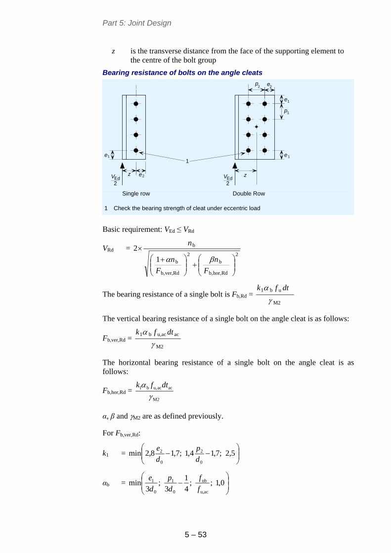
Part 5: Joint Design
5 – 53
z is the transverse distance from the face of the supporting element to the centre of the bolt group
Bearing resistance of bolts on the angle cleats
ezEd Ed2 2
e e
e
ep
p
2 2
1
11
2
1
zVV
1
Single row Double Row
1 Check the bearing strength of cleat under eccentric load
Basic requirement: VEd ≤ VRd
VRd = 2
Rdhor,b,
b
2
Rdver,b,
b
b
1
2
F
n
F
n
n
The bearing resistance of a single bolt is Fb,Rd = M2
ub1
dtfk
The vertical bearing resistance of a single bolt on the angle cleat is as follows:
Fb,ver,Rd = M2
acacu,b1
dtfk
The horizontal bearing resistance of a single bolt on the angle cleat is as follows:
Fb,hor,Rd = M2
acacu,b1
dtfk
α, β and M2 are as defined previously.
For Fb,ver,Rd:
k1 =
5,2;7,14,1;7,18,2min
0
2
0
2
d
p
d
e
αb =
0,1;;
4
1
3;
3min
acu,
ub
0
1
0
1
f
f
d
p
d
e
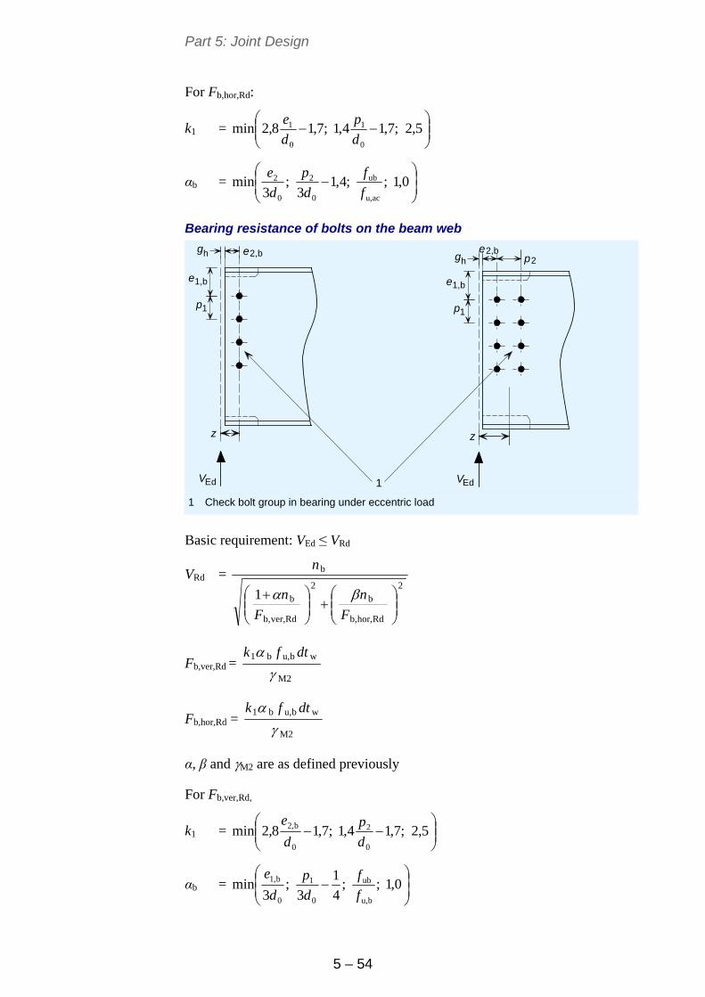
Part 5: Joint Design
5 – 54
For Fb,hor,Rd:
k1 =
5,2;7,14,1;7,18,2min
0
1
0
1
d
p
d
e
αb =
0,1;;4,1
3;
3min
acu,
ub
0
2
0
2
f
f
d
p
d
e
Bearing resistance of bolts on the beam web
1,b
Ed
e2,bhg
e 1,b
Ed
e2,bhg
e
p2
z z
p1 p1
V V1 1 Check bolt group in bearing under eccentric load
Basic requirement: VEd ≤ VRd
VRd = 2
Rdhor,b,
b
2
Rdver,b,
b
b
1
F
n
F
n
n
Fb,ver,Rd = M2
wbu,b1
dtfk
Fb,hor,Rd = M2
wbu,b1
dtfk
α, β and M2 are as defined previously
For Fb,ver,Rd,
k1 =
5,2;7,14,1;7,18,2min
0
2
0
b2,
d
p
d
e
αb =
0,1;;
4
1
3;
3min
bu,
ub
0
1
0
b1,
f
f
d
p
d
e
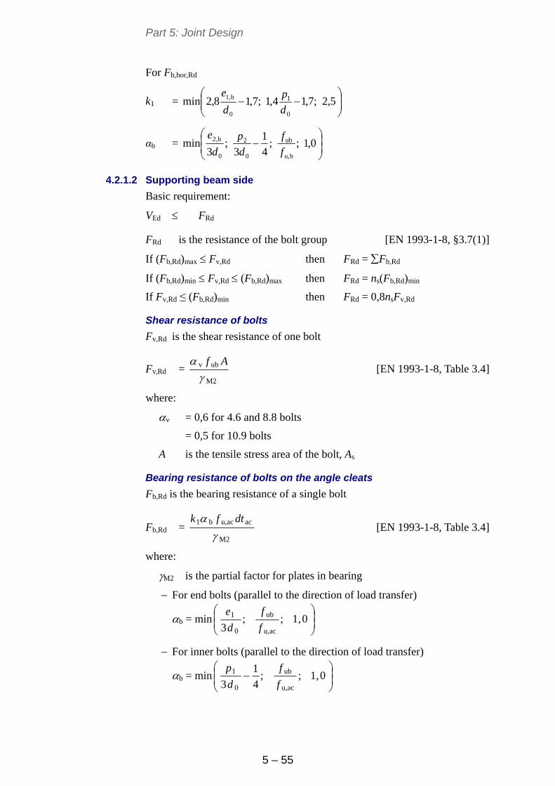
Part 5: Joint Design
5 – 55
For Fb,hor,Rd
k1 =
5,2;7,14,1;7,18,2min
0
1
0
b1,
d
p
d
e
αb =
0,1;;
4
1
3;
3min
bu,
ub
0
2
0
b2,
f
f
d
p
d
e
4.2.1.2 Supporting beam side
Basic requirement:
VEd FRd
FRd is the resistance of the bolt group [EN 1993-1-8, §3.7(1)]
If (Fb,Rd)max Fv,Rd then FRd = Fb,Rd
If (Fb,Rd)min Fv,Rd (Fb,Rd)max then FRd = ns(Fb,Rd)min
If Fv,Rd ≤ (Fb,Rd)min then FRd = 0,8nsFv,Rd
Shear resistance of bolts
Fv,Rd is the shear resistance of one bolt
Fv,Rd = M2
ubv
Af
[EN 1993-1-8, Table 3.4]
where:
v = 0,6 for 4.6 and 8.8 bolts
= 0,5 for 10.9 bolts
A is the tensile stress area of the bolt, As
Bearing resistance of bolts on the angle cleats
Fb,Rd is the bearing resistance of a single bolt
Fb,Rd = M2
acacu,b1
dtfk
[EN 1993-1-8, Table 3.4]
where:
M2 is the partial factor for plates in bearing
For end bolts (parallel to the direction of load transfer)
b = min
0,1;;
3 acu,
ub
0
1
f
f
d
e
For inner bolts (parallel to the direction of load transfer)
b = min
0,1;;
4
1
3 acu,
ub
0
1
f
f
d
p
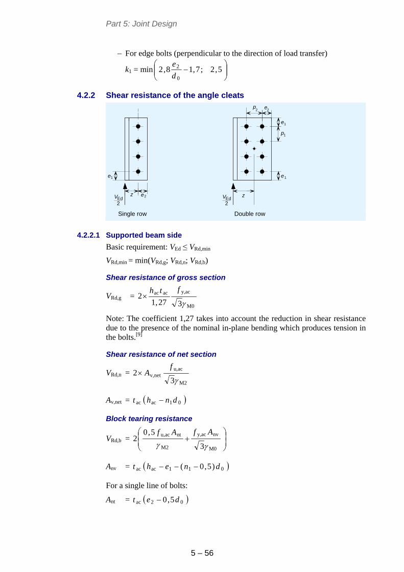
Part 5: Joint Design
5 – 56
For edge bolts (perpendicular to the direction of load transfer)
k1 = min
5,2;7,18,2
0
2
d
e
4.2.2 Shear resistance of the angle cleats
ezEd Ed2 2
e e
e
ep
p
2 2
1
11
2
1
zVV
Single row Double row
4.2.2.1 Supported beam side
Basic requirement: VEd ≤ VRd,min
VRd,min = min(VRd,g; VRd,n; VRd,b)
Shear resistance of gross section
VRd,g = M0
acy,acac
327,12
fth
Note: The coefficient 1,27 takes into account the reduction in shear resistance due to the presence of the nominal in-plane bending which produces tension in the bolts.[9]
Shear resistance of net section
VRd,n = M2
acu,netv,
32
fA
Av,net = 01acac dnht
Block tearing resistance
VRd,b =
M0
nvacy,
M2
ntacu,
3
5,02
AfAf
Anv = 011acac )5,0( dneht
For a single line of bolts:
Ant = 02ac 5,0 det
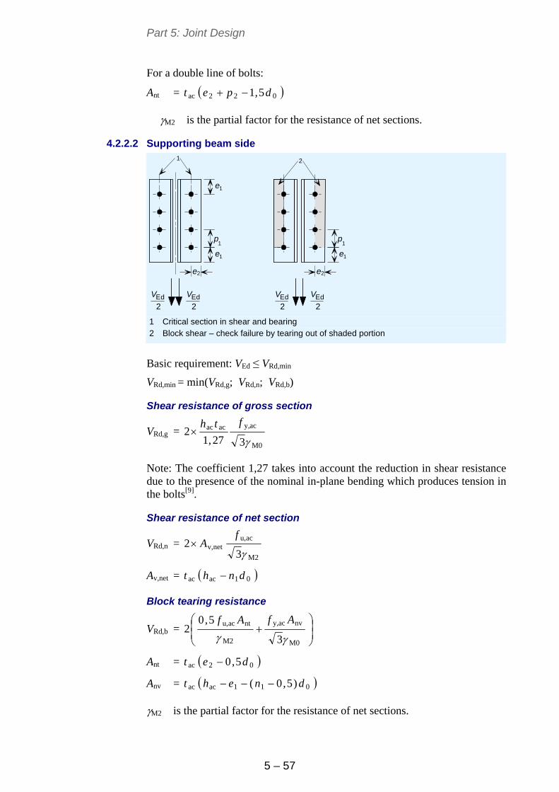
Part 5: Joint Design
5 – 57
For a double line of bolts:
Ant = 022ac 5,1 dpet
M2 is the partial factor for the resistance of net sections.
4.2.2.2 Supporting beam side
e
e e
1
1
1 1
1
Ed EdEd Ed
2 22 2
2 2e e
V V V V
p p
1 2
1 Critical section in shear and bearing 2 Block shear – check failure by tearing out of shaded portion
Basic requirement: VEd ≤ VRd,min
VRd,min = min(VRd,g; VRd,n; VRd,b)
Shear resistance of gross section
VRd,g = M0
acy,acac
327,12
fth
Note: The coefficient 1,27 takes into account the reduction in shear resistance due to the presence of the nominal in-plane bending which produces tension in the bolts[9].
Shear resistance of net section
VRd,n = M2
acu,netv,
32
fA
Av,net = 01acac dnht
Block tearing resistance
VRd,b =
M0
nvacy,
M2
ntacu,
3
5,02
AfAf
Ant = 02ac 5,0 det
Anv = 011acac )5,0( dneht
M2 is the partial factor for the resistance of net sections.
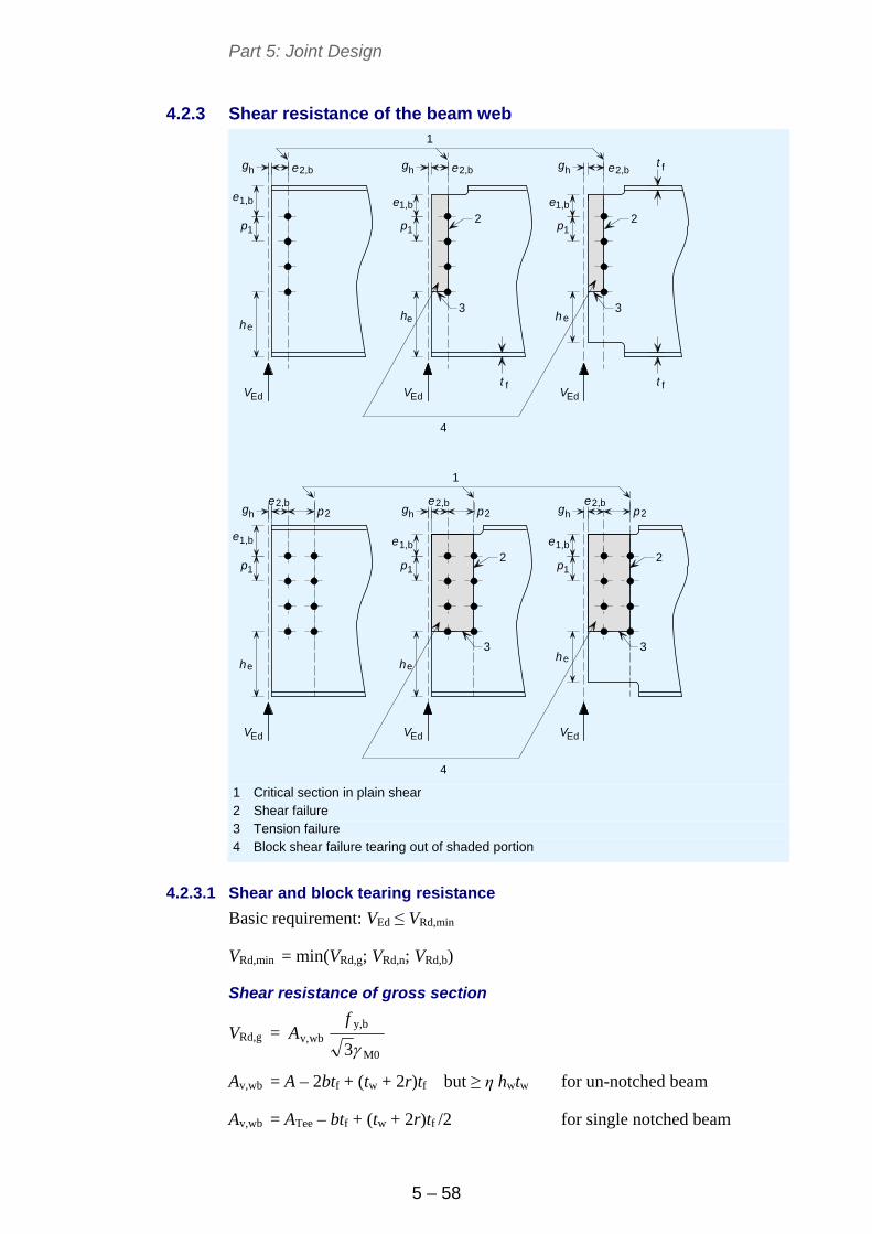
Part 5: Joint Design
5 – 58
4.2.3 Shear resistance of the beam web
t f
f ft t
1,b 1,b
ee e
Ed Ed Ed
e
h h
e e e2,b 2,b 2,bh h hg g g
e 1,be
1,b
e
Ed
h
e2,bhg
e
e
Ed
h e
Ed
h
hg
1,b1,b
hg
e e
h
p2e2,b
p2e2,b
p2
p
p
p
p
p
p
1
1
1
1
1
1
V V V
V V V
1
3
2 2
3
4
1
4
2 2
3 3
1 Critical section in plain shear 2 Shear failure 3 Tension failure 4 Block shear failure tearing out of shaded portion
4.2.3.1 Shear and block tearing resistance
Basic requirement: VEd ≤ VRd,min
VRd,min = min(VRd,g; VRd,n; VRd,b)
Shear resistance of gross section
VRd,g = M0
by,wbv,
3
fA
Av,wb = A – 2btf + (tw + 2r)tf but ≥ η hwtw for un-notched beam
Av,wb = ATee – btf + (tw + 2r)tf /2 for single notched beam
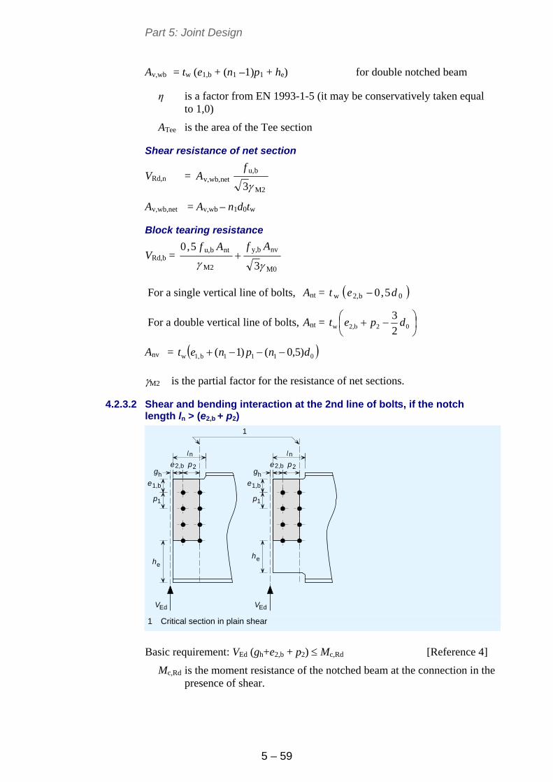
Part 5: Joint Design
5 – 59
Av,wb = tw (e1,b + (n1 –1)p1 + he) for double notched beam
η is a factor from EN 1993-1-5 (it may be conservatively taken equal to 1,0)
ATee is the area of the Tee section
Shear resistance of net section
VRd,n = M2
bu,netwb,v,
3
fA
Av,wb,net = Av,wb – n1d0tw
Block tearing resistance
VRd,b = M0
nvby,
M2
ntbu,
3
5,0
AfAf
For a single vertical line of bolts, Ant = 0b2,w 5,0 det
For a double vertical line of bolts, Ant =
02b2,w 2
3dpet
Anv = 0111b1,w )5,0()1( dnpnet
M2 is the partial factor for the resistance of net sections.
4.2.3.2 Shear and bending interaction at the 2nd line of bolts, if the notch length ln > (e2,b + p2)
e
Ed
h e
Ed
h
hg
1,b1,b
hg
e e
e2,b p2
n
e2,b p2
n
p1 p1
V V
l l
1
1 Critical section in plain shear
Basic requirement: VEd (gh+e2,b + p2) Mc,Rd [Reference 4]
Mc,Rd is the moment resistance of the notched beam at the connection in the presence of shear.
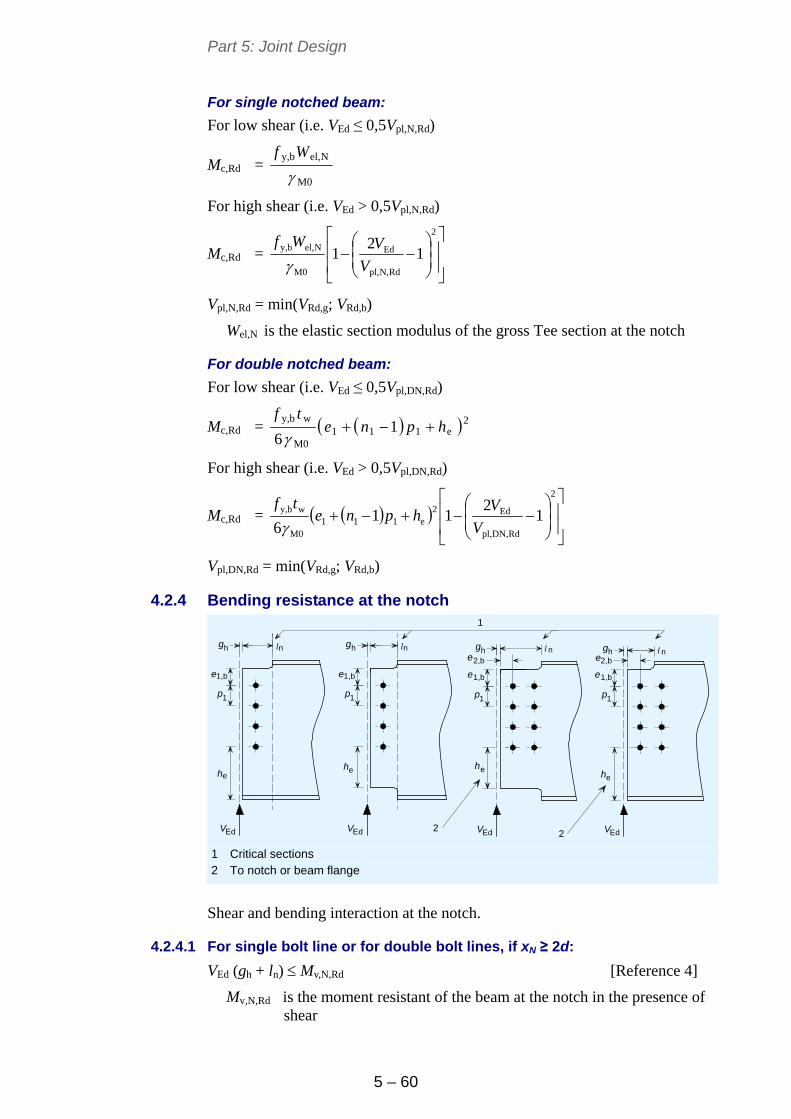
Part 5: Joint Design
5 – 60
For single notched beam:
For low shear (i.e. VEd ≤ 0,5Vpl,N,Rd)
Mc,Rd = M0
Nel,by,
Wf
For high shear (i.e. VEd > 0,5Vpl,N,Rd)
Mc,Rd =
2
RdN,pl,
Ed
M0
Nel,by, 12
1V
VWf
Vpl,N,Rd = min(VRd,g; VRd,b)
Wel,N is the elastic section modulus of the gross Tee section at the notch
For double notched beam:
For low shear (i.e. VEd ≤ 0,5Vpl,DN,Rd)
Mc,Rd = 2e111
M0
wby,1
6hpne
tf
For high shear (i.e. VEd > 0,5Vpl,DN,Rd)
Mc,Rd =
2
RdDN,pl,
Ed2e111
M0
wby, 12
116 V
Vhpne
tf
Vpl,DN,Rd = min(VRd,g; VRd,b)
4.2.4 Bending resistance at the notch
ee
Ed Ed
e
h
h hg g
1,be
e
Ed
e
Ed
h
hg
1,b1,b
h
e e
n n
h
nn
1 111
1,b
p ppp
g
V V V V
2,b 2,b
l lll
ee
1
h
22
1 Critical sections 2 To notch or beam flange
Shear and bending interaction at the notch.
4.2.4.1 For single bolt line or for double bolt lines, if xN ≥ 2d:
VEd (gh + ln) Mv,N,Rd [Reference 4]
Mv,N,Rd is the moment resistant of the beam at the notch in the presence of shear
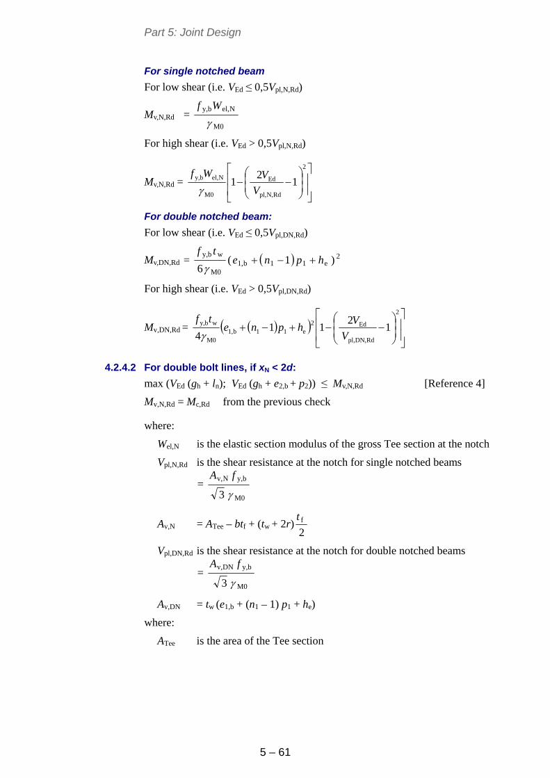
Part 5: Joint Design
5 – 61
For single notched beam
For low shear (i.e. VEd ≤ 0,5Vpl,N,Rd)
Mv,N,Rd = M0
Nel,by,
Wf
For high shear (i.e. VEd > 0,5Vpl,N,Rd)
Mv,N,Rd =
2
RdN,pl,
Ed
M0
Nel,by, 1
21
V
VWf
For double notched beam:
For low shear (i.e. VEd ≤ 0,5Vpl,DN,Rd)
Mv,DN,Rd = 2e11b1,
M0
wby,)1(
6hpne
tf
For high shear (i.e. VEd > 0,5Vpl,DN,Rd)
Mv,DN,Rd =
2
RdDN,pl,
Ed2e11b1,
M0
wby, 1
211
4 V
Vhpne
tf
4.2.4.2 For double bolt lines, if xN < 2d:
max (VEd (gh + ln); VEd (gh + e2,b + p2)) ≤ Mv,N,Rd [Reference 4]
Mv,N,Rd = Mc,Rd from the previous check
where:
Wel,N is the elastic section modulus of the gross Tee section at the notch
Vpl,N,Rd is the shear resistance at the notch for single notched beams
= M0
by,Nv,
3
fA
Av,N = ATee – btf + (tw + 2r)2ft
Vpl,DN,Rd is the shear resistance at the notch for double notched beams
= M0
by,DNv,
3
fA
Av,DN = tw (e1,b + (n1 – 1) p1 + he)
where:
ATee is the area of the Tee section
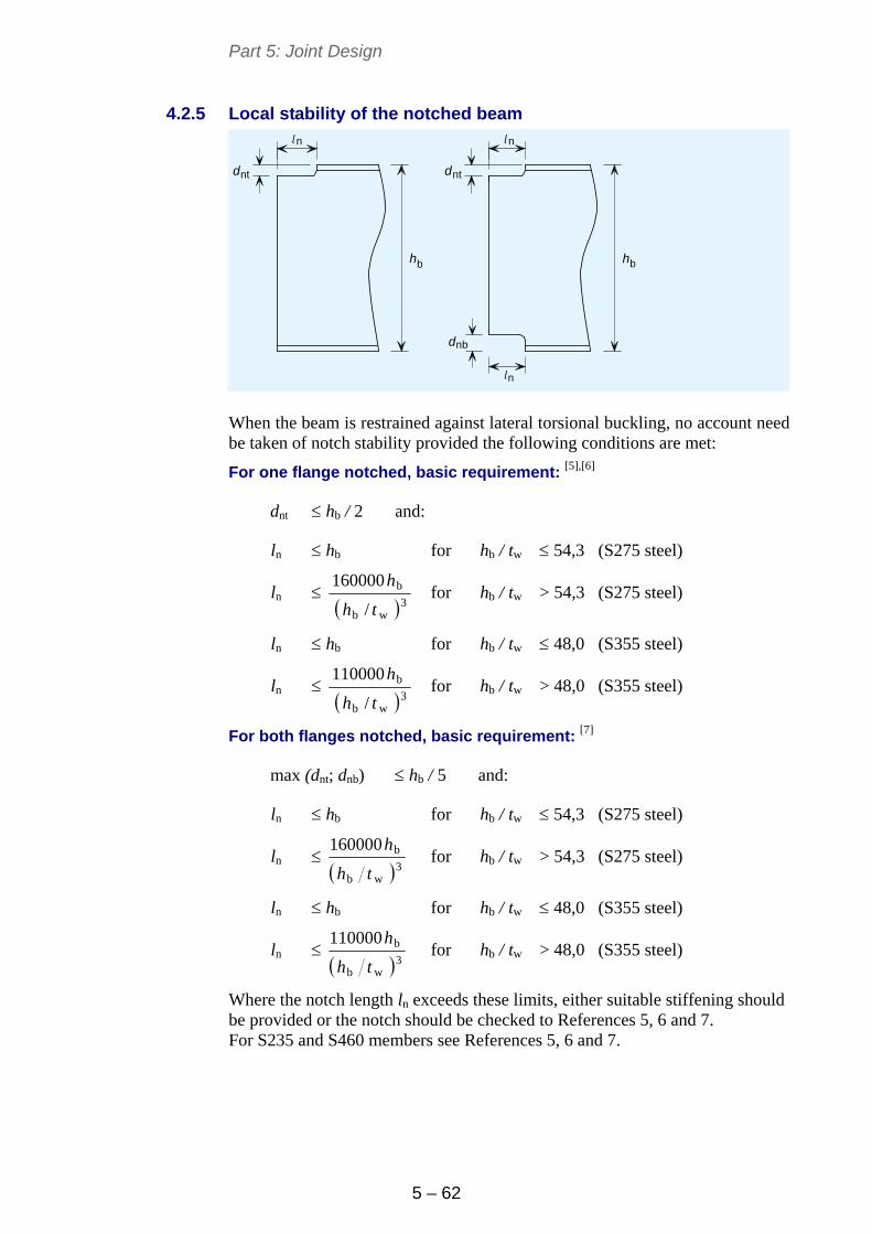
Part 5: Joint Design
5 – 62
4.2.5 Local stability of the notched beam
n
h h
n
n
dd
d
nt nt
nb
l l
l
b b
When the beam is restrained against lateral torsional buckling, no account need be taken of notch stability provided the following conditions are met:
For one flange notched, basic requirement: [5],[6]
dnt hb / 2 and:
ln hb for hb / tw 54,3 (S275 steel)
ln 3
wb
b
/
160000
th
h for hb / tw > 54,3 (S275 steel)
ln hb for hb / tw 48,0 (S355 steel)
ln 3
wb
b
/
110000
th
h for hb / tw > 48,0 (S355 steel)
For both flanges notched, basic requirement: [7]
max (dnt; dnb) hb / 5 and:
ln hb for hb / tw 54,3 (S275 steel)
ln 3
wb
b160000
th
h for hb / tw > 54,3 (S275 steel)
ln hb for hb / tw 48,0 (S355 steel)
ln 3
wb
b110000
th
h for hb / tw > 48,0 (S355 steel)
Where the notch length ln exceeds these limits, either suitable stiffening should be provided or the notch should be checked to References 5, 6 and 7. For S235 and S460 members see References 5, 6 and 7.
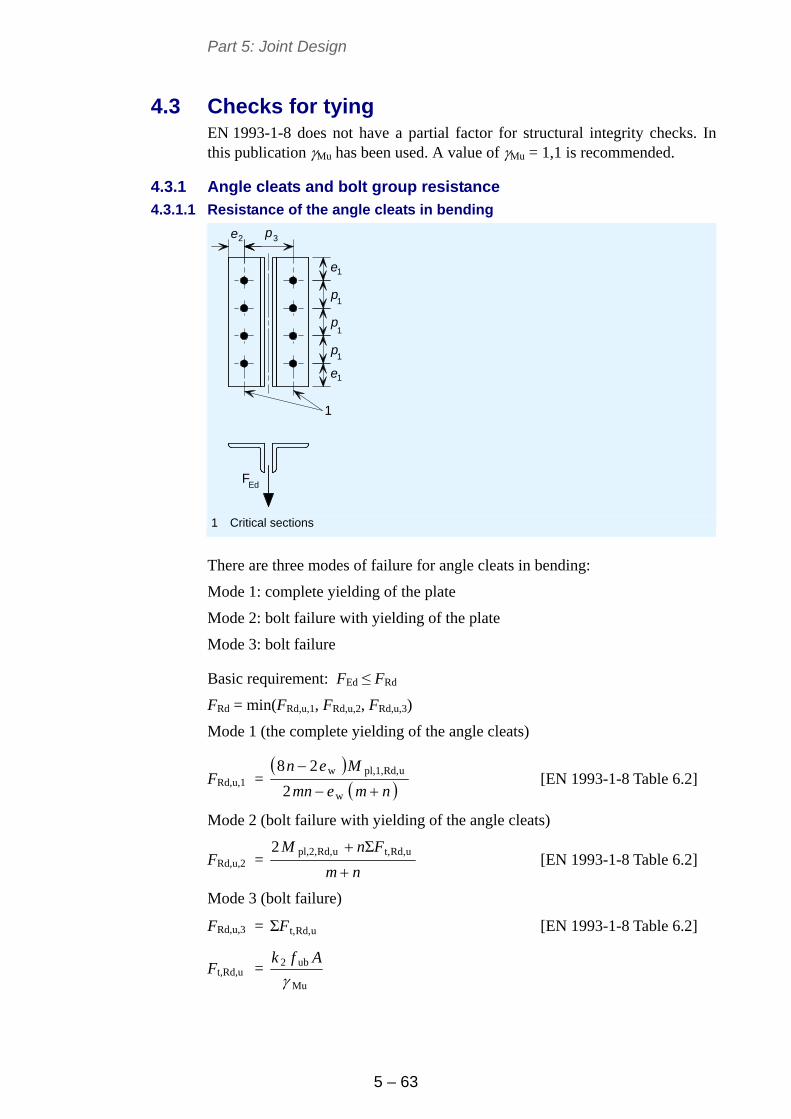
Part 5: Joint Design
5 – 63
4.3 Checks for tying EN 1993-1-8 does not have a partial factor for structural integrity checks. In this publication Mu has been used. A value of Mu = 1,1 is recommended.
4.3.1 Angle cleats and bolt group resistance
4.3.1.1 Resistance of the angle cleats in bending
e
e
1
1
1
1
1
2e p
p
p
p
3
FEd
1
1 Critical sections
There are three modes of failure for angle cleats in bending:
Mode 1: complete yielding of the plate
Mode 2: bolt failure with yielding of the plate
Mode 3: bolt failure
Basic requirement: FEd ≤ FRd
FRd = min(FRd,u,1, FRd,u,2, FRd,u,3)
Mode 1 (the complete yielding of the angle cleats)
FRd,u,1 =
nmemn
Men
w
uRd,pl,1,w
2
28 [EN 1993-1-8 Table 6.2]
Mode 2 (bolt failure with yielding of the angle cleats)
FRd,u,2 = nm
FnM
uRd,t,uRd,pl,2, Σ2 [EN 1993-1-8 Table 6.2]
Mode 3 (bolt failure)
FRd,u,3 = uRd,t,ΣF [EN 1993-1-8 Table 6.2]
Ft,Rd,u = Mu
ub2
Afk
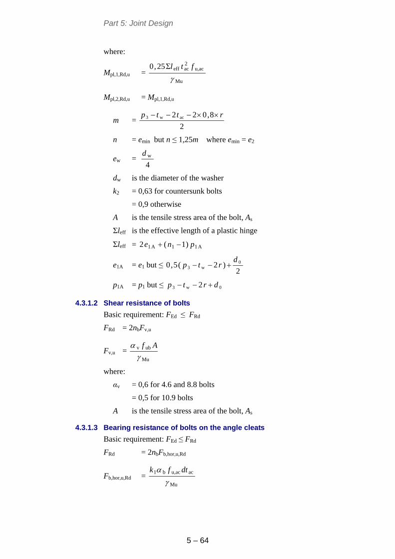
Part 5: Joint Design
5 – 64
where:
Mpl,1,Rd,u = Mu
acu,2aceffΣ25,0
ftl
Mpl,2,Rd,u = Mpl,1,Rd,u
m = 2
8,022 acw3 rttp
n = emin but n ≤ 1,25m where emin = e2
ew = 4wd
dw is the diameter of the washer
k2 = 0,63 for countersunk bolts
= 0,9 otherwise
A is the tensile stress area of the bolt, As
Σleff is the effective length of a plastic hinge
Σleff = A11A1 )1(2 pne
e1A = e1 but ≤ 2
)2(5,0 0w3
drtp
p1A = p1 but ≤ 0w3 2 drtp
4.3.1.2 Shear resistance of bolts
Basic requirement: FEd ≤ FRd
FRd = 2nbFv,u
Fv,u = Mu
ubv
Af
where:
αv = 0,6 for 4.6 and 8.8 bolts
= 0,5 for 10.9 bolts
A is the tensile stress area of the bolt, As
4.3.1.3 Bearing resistance of bolts on the angle cleats
Basic requirement: FEd ≤ FRd
FRd = 2nbFb,hor,u,Rd
Fb,hor,u,Rd = Mu
acacu,b1
dtfk
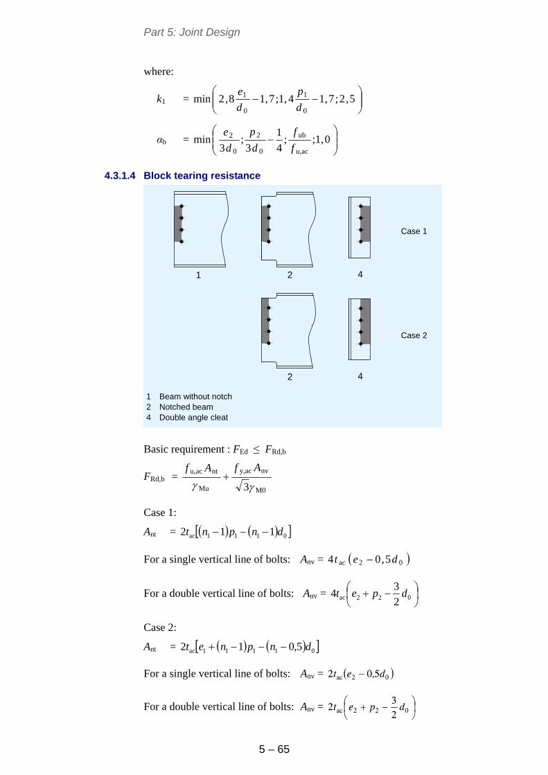
Part 5: Joint Design
5 – 65
where:
k1 =
5,2;7,14,1;7,18,2min
0
1
0
1
d
p
d
e
αb =
0,1;;
4
1
3;
3min
acu,
ub
0
2
0
2
f
f
d
p
d
e
4.3.1.4 Block tearing resistance
Case 1
1 2 4
2 4
Case 2
1 Beam without notch 2 Notched beam 4 Double angle cleat
Basic requirement : FEd ≤ FRd,b
FRd,b = M0
nvacy,
Mu
ntacu,
3AfAf
Case 1:
Ant = 0111ac 112 dnpnt
For a single vertical line of bolts: Anv = 02ac 5,04 det
For a double vertical line of bolts: Anv =
022ac 2
34 dpet
Case 2:
Ant = 01111ac 5,012 dnpnet
For a single vertical line of bolts: Anv = 02ac 5,02 det
For a double vertical line of bolts: Anv =
022ac 2
32 dpet
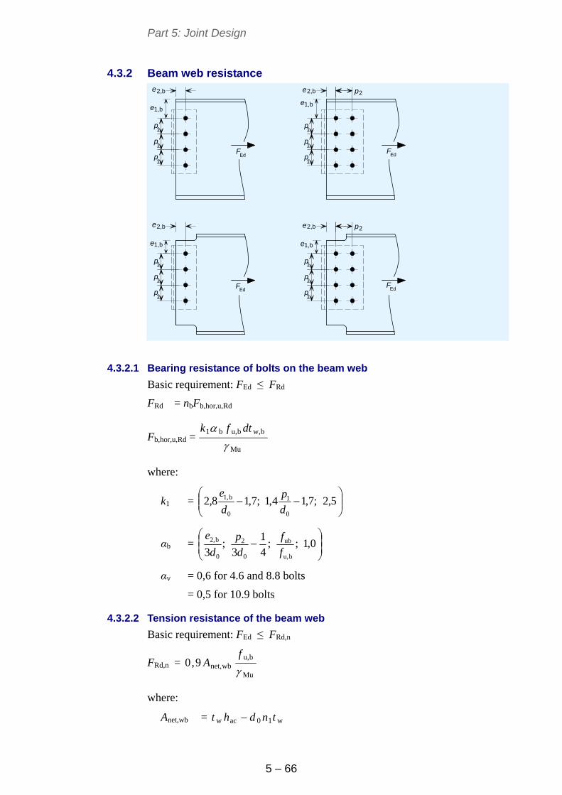
Part 5: Joint Design
5 – 66
4.3.2 Beam web resistance
1,b
1,b
1,b
1,b
e
e
e
e
p
p
p
p
p
p
p
p
p
p
p
p
2,b
2,b
2,b
2,b
p
p
2
2
e
e
e
e
1
1
1
1
1
1
1
1
1
1
1
1Ed Ed
Ed Ed
F F
F F
4.3.2.1 Bearing resistance of bolts on the beam web
Basic requirement: FEd ≤ FRd
FRd = nbFb,hor,u,Rd
Fb,hor,u,Rd = Mu
bw,bu,b1
dtfk
where:
k1 =
5,2;7,14,1;7,18,2
0
1
0
b1,
d
p
d
e
αb =
0,1;;
4
1
3;
3 bu,
ub
0
2
0
b2,
f
f
d
p
d
e
αv = 0,6 for 4.6 and 8.8 bolts
= 0,5 for 10.9 bolts
4.3.2.2 Tension resistance of the beam web
Basic requirement: FEd ≤ FRd,n
FRd,n = Mu
bu,wbnet,9,0
f
A
where:
Anet,wb = w10acw tndht
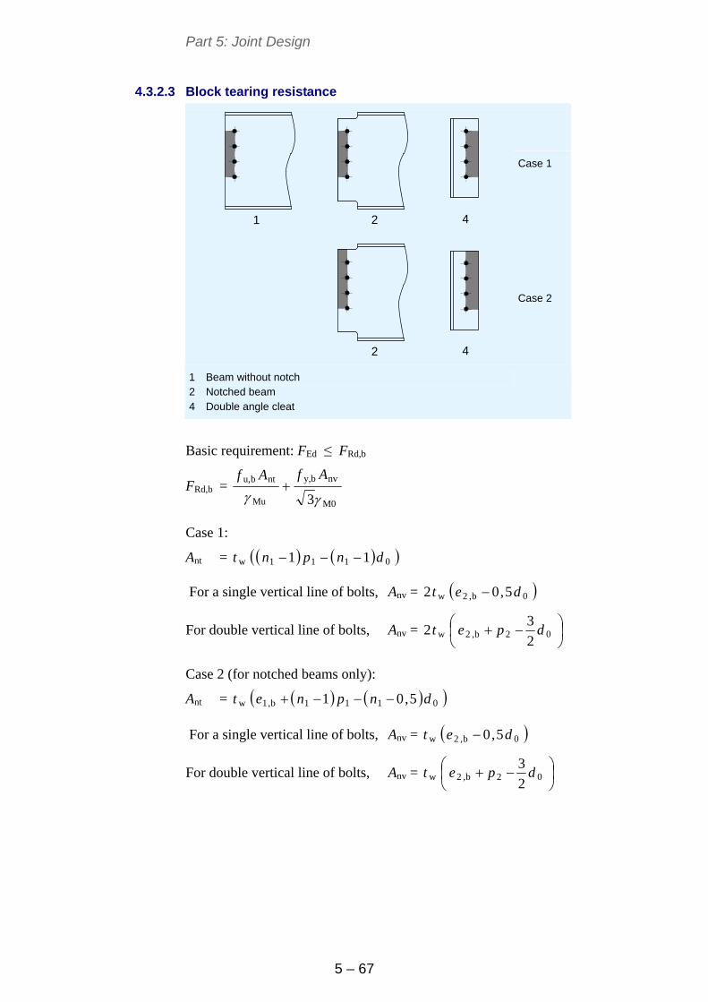
Part 5: Joint Design
5 – 67
4.3.2.3 Block tearing resistance
Case 1
1 2 4
2 4
Case 2
1 Beam without notch 2 Notched beam 4 Double angle cleat
Basic requirement: FEd ≤ FRd,b
FRd,b = M0
nvby,
Mu
ntbu,
3AfAf
Case 1:
Ant = 0111w 11 dnpnt
For a single vertical line of bolts, Anv = 0b,2w 5,02 det
For double vertical line of bolts, Anv =
02b,2w
2
32 dpet
Case 2 (for notched beams only):
Ant = 0111b,1w 5,01 dnpnet
For a single vertical line of bolts, Anv = 0b,2w 5,0 det
For double vertical line of bolts, Anv =
02b,2w
2
3dpet
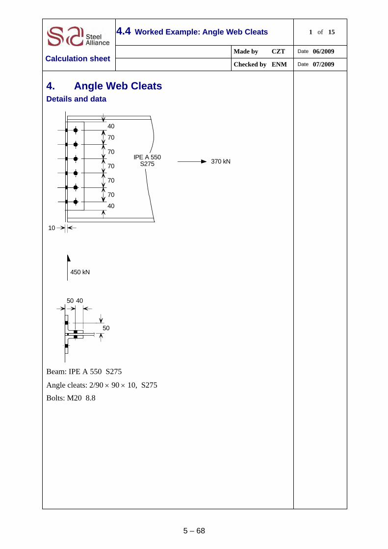
5 – 68
4.4 Worked Example: Angle Web Cleats 1 of 15
Made by CZT Date 06/2009
Calculation sheet Checked by ENM Date 07/2009
4. Angle Web Cleats Details and data
40
40
70
70
70
70
70
50
450 kN
370 kNIPE A 550
S275
50 40
10
Beam: IPE A 550 S275
Angle cleats: 2/90 90 10, S275
Bolts: M20 8.8
Title 4.4 Worked Example – Angle Web Cleats 2 of 15
5 - 69
Summary of full design checks
Design forces
VEd = 450 kN
FEd = 370 kN (Tie force)
Shear resistances
Bolt group resistance
Supported beam side
Shear resistance of bolts 962 kN
Bearing resistance of bolts on the angle cleats 1075 kN
Bearing resistance of bolts on the beam web 583 kN
Supporting beam side
Resistance 902 kN
Shear resistance of the angle cleats
Supported beam side
Shear resistance 954 kN
Supporting beam side
Shear resistance 954 kN
Shear resistance of the beam web
Shear and block tearing resistance
Shear resistance 501 kN
Shear and bending interaction at the 2nd line of bolts N/A
Bending resistance at the notch N/A
Local stability of the notched beam N/A
Tying resistances
Angle cleats and bolt group resistance
Resistance of the angle cleats in bending 696 kN
Shear resistance of bolts 1284 kN
Bearing resistance of bolts on the angle cleats 1428 kN
Block tearing resistance 2060 kN
Beam web resistance
Bearing resistance of bolts on the beam web 642 kN
Tension resistance of the beam web 944 kN
Block tearing resistance 927 kN
Title 4.4 Worked Example – Angle Web Cleats 3 of 15
5 - 70
4.1. Recommended details
Cleats 10 mm thick
Length, hac = 430mm > 0,6hb, OK
Unless noted otherwise, all references are to EN 1993-1-8
4.2. Checks for vertical shear
4.2.1. Bolt group resistance
4.2.1.1. Supported beam side
Shear resistance of bolts
Basic requirement: VEd ≤ VRd
VRd = 2
b2
b
Rdv,b
)()(12
nn
Fn
Fv,Rd = M2
ubv
Af
For M20 8.8 bolts, Fv,Rd = 31025,1
2458006,0
= 94 kN
For a single vertical line of bolts (i.e. n2 = 1 and n1 = 6), α = 0
β = 111 )1(
6
pnn
z
= 70166
506
= 0,102
Thus VRd = 22 )6102,0()60(1
9462
= 962 kN
VEd = 450 kN ≤ 962 kN, OK
Bearing resistance of bolts on the angle cleats
Basic requirement: VEd ≤ Vb,Rd
Vb,Rd = 2
Rdhor,b,
b
2
Rdver,b,
b
b
1
2
F
n
F
n
n
α = 0 and β = 0,102, as above
The vertical bearing resistance for a single bolt, Fb,ver,Rd = M2
acacu,b1
dtfk
k1 =
5,2;7,18,2min
0
2
d
e=
5,2;7,1
22
408,2min = 5,2;39,3min
= 2,5
Title 4.4 Worked Example – Angle Web Cleats 4 of 15
5 - 71
αb =
0,1;;
4
1
3;
3min
acu,
ub
0
1
0
1
f
f
d
p
d
e
=
0,1;
430
800;25,0
223
70;
223
40min = 0,1;86,1;81,0;61,0min
αb = 0,61
Fb,ver,Rd = 31025,1
102043061,05,2
= 105 kN
The horizontal bearing resistance for a single bolt, Fb,hor,Rd = M2
acacu,b1
dtfk
k1 =
5,2;7,14,1;7,18,2min
0
1
0
1
d
p
d
e
=
5,2;7,1
22
704,1;7,1
22
408,2min = 5,2;75,2;39,3min = 2,5
αb =
0,1;;
3min
acu,
ub
0
2
f
f
d
e =
0,1;
430
800;
223
40min
= 0,1;86,1;61,0min = 0,61
Fb,hor,Rd = 31025,1
102043061,05,2
= 105 kN
VRd = 22
105
6102,0
105
601
62
= 1075 kN
VEd = 450 kN ≤ 1075 kN, OK
Title 4.4 Worked Example – Angle Web Cleats 5 of 15
5 - 72
Bearing resistance of bolts on the beam web
he
= 35011
e1,b
t w
= 90
(n -1)p
e2,b
= 9
= 40
= 107
Basic requirement: VEd ≤ VRd
VRd = 2
Rdhor,b,
b
2
Rdver,b,
b
b
1
F
n
F
n
n
α = 0 and β = 0,102, as above
The vertical bearing resistance of a single bolt, Fb,ver,Rd = M2
wbu,b1
dtfk
k1 =
5,2;7,18,2min
0
b2,
d
e =
5,2;7,1
22
408,2min = 5,2;4,3min
= 2,5
αb =
0,1;;
4
1
3;
3min
bu,
ub
0
1
0
b1,
f
f
d
p
d
e=
0,1;
430
800;
4
1
223
70;
223
90min
= 0,1;86,1;81,0;36,1min = 0,81
Fb,ver,Rd = 31025,1
92043081,05,2
= 125 kN
The horizontal bearing resistance of a single bolt,
Fb,hor,Rd = M2
wbu,b1
dtfk
k1 =
5,2;7,14,1;7,18,2min
0
1
0
b1,
d
p
d
e
=
5,2;7,1
22
704,1;7,1
22
908,2min = 5,2;75,2;75,9min = 2,5
Title 4.4 Worked Example – Angle Web Cleats 6 of 15
5 - 73
αb =
0,1;;
3min
bu,
ub
0
b2,
f
f
d
e=
0,1;
430
800;
223
40min
= 0,1;86,1;61,0min = 0,61
Fb,hor,Rd = 31025,1
92043061,05,2
= 94 kN
VRd = 22
94
6102,0
125
601
6
= 583 kN
VEd = 450 kN ≤ 583 kN, OK
4.2.1.2. Supporting beam side
e1 = 40
= 40
e1 = 40
Ed Ed2 2
Ed
= 350(n -1)p11
V V
V = 450 kN
e2
Basic requirement: RdEd FV
The design resistance of the bolt group, RdF :
If Rdv,maxRdb, FF then Rdb,Rd ΣFF
If maxRdb,Rdv,minRdb, )()( FFF then minRdb,sRd )( FnF
If minRdb,Rdv, FF then Rdv,sRd 8,0 FnF
Shear resistance of bolts
The shear resistance of a single bolt, Fv,Rd = M2
ubv
Af
For M20 8.8 bolts, Fv,Rd = 31025,1
2458006,0
= 94 kN
Title 4.4 Worked Example – Angle Web Cleats 7 of 15
5 - 74
Bearing resistance of bolts on the angle cleats
Vb,Rd = M2
acacu,b1
dtfk
For edge bolts, k1 = )5,2;7,18,2min(0
2 d
e = )5,2;7,1
22
408,2min(
= )5,2;39,3min( = 2,5
For end bolts, αb = )0,1;;3
min(acu,
ub
0
1
f
f
d
e = )0,1;
430
800;
223
40min(
= )0,1;86,1;61,0min( = 0,61
For inner bolts, αb = )0,1;;4
1
3min(
acu,
ub
0
1
f
f
d
p
= )0,1;430
800;
4
1
223
70min(
= )0,1;86,1;81,0min(
= 0,81
End bolts, minRdb,endRd,b, FF 310
25,1
102043061,05,2
105 kN
Inner bolts, maxRdb,innerRd,b, FF 310
25,1
102043081,05,2
139 kN
94 kN < 105 kN thus Fv,Rd < (Fb,Rd)min
90294128,08,0 Rdv,sRd FnF kN
EdV = 550 kN ≤ 902 kN, OK
4.2.2. Shear resistance of the angle cleats
4.2.2.1. Supported beam side
Basic requirement: VEd ≤ VRd,min
VRd,min = min(VRd,g; VRd,n; VRd,b)
Shear resistance of gross section
VRd,g = M0
acy,acac
327,12
fth = 310
0,1327,1
275104302
= 1076 kN
Shear resistance of net section
VRd,n = M2
acu,netv,
32
fA
Title 4.4 Worked Example – Angle Web Cleats 8 of 15
5 - 75
Net area, Av,net = 01acac dnht = 22643010 = 2980 mm2
VRd,n = 31025,13
43029802
= 1184 kN
Block tearing resistance
VRd,b =
M0
nvacy,
M2
ntacu,
3
5,02
AfAf
Net area subject to tension, Ant = 02ac 5,0 det
= 225,04010 = 290 mm2
Net area subject to shear, Anv = 011acac )5,0( dneht
= 22)5,06(4043010 = 2690 mm2
VRd,b = 3100,13
2690275
25,1
2904305,02
= 954 kN
VRd,min = 954 kN
VEd = 450 kN ≤ 954 kN, OK
4.2.2.2. Supporting beam side
e1 = 40
= 40
e1 = 40
Ed Ed2 2
Ed
= 350(n -1)p11
V V
V = 450 kN
e2
1
1 Block shear failure
Basic requirement: VEd ≤ VRd,min
VRd,min = min(VRd,g; VRd,n; VRd,b)
Shear resistance of gross section
VRd,g = M0
acy,acac
327,12
fth = 310
0,1327,1
275104302
= 1076 kN
Title 4.4 Worked Example – Angle Web Cleats 9 of 15
5 - 76
Shear resistance of net section
VRd,n = M2
acu,netv,
32
fA
Net area, Av,net = 01acac dnht = 22643010 = 2980 mm2
VRd,n = 31025,13
43029802
= 1184 kN
Block tearing resistance
VRd,b =
M0
nvacy,
M2
ntacu,
3
5,02
AfAf
Net area subject to tension, Ant = 02ac 5,0 det
= 225,04010 = 290 mm2
Net area subject to shear, Anv = 011acac )5,0( dneht
= 22)5,06(4043010 = 2690 mm2
VRd,b = 3100,13
2690275
25,1
2904305,02
= 954 kN
VRd,min = 954 kN
VEd = 450 kN ≤ 954 kN, OK
4.2.3. Shear resistance of the beam web
4.2.3.1. Shear and block tearing resistance
EdV = 450 kN
hac = 430
Basic requirement: VEd ≤ VRd,min
VRd,min = min(VRd,g; VRd,n; VRd,b)
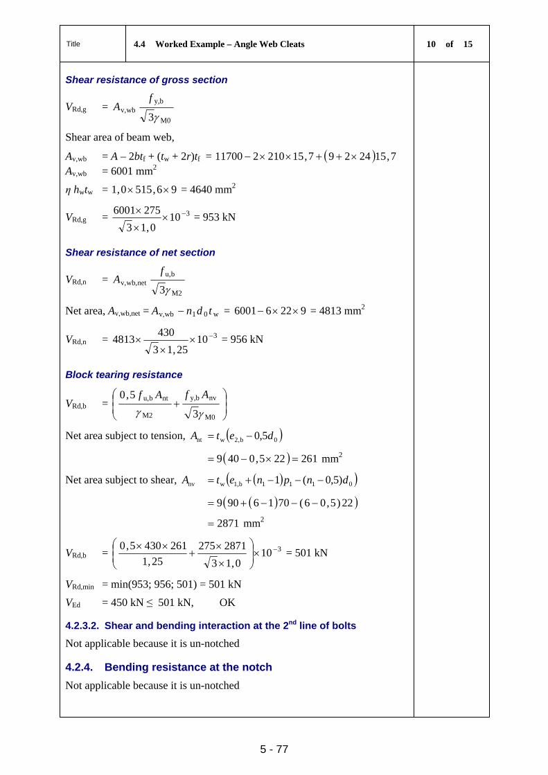
Title 4.4 Worked Example – Angle Web Cleats 10 of 15
5 - 77
Shear resistance of gross section
VRd,g = M0
by,wbv,
3
fA
Shear area of beam web,
Av,wb = A – 2btf + (tw + 2r)tf = 7,1524297,15210211700 Av,wb = 6001 mm2
η hwtw = 96,5150,1 = 4640 mm2
VRd,g = 3100,13
2756001
= 953 kN
Shear resistance of net section
VRd,n = M2
bu,netwb,v,
3
fA
Net area, Av,wb,net = w01wbv, tdnA = 92266001 = 4813 mm2
VRd,n = 31025,13
4304813
= 956 kN
Block tearing resistance
VRd,b =
M0
nvby,
M2
ntbu,
3
5,0
AfAf
Net area subject to tension, ntA 0b,2w 5,0 det
261225,0409 mm2
Net area subject to shear, nvA 0111b1,w )5,0(1 dnpnet
22)5,06(7016909
2871 mm2
VRd,b = 3100,13
2871275
25,1
2614305,0
= 501 kN
VRd,min = min(953; 956; 501) = 501 kN
VEd = 450 kN ≤ 501 kN, OK
4.2.3.2. Shear and bending interaction at the 2nd line of bolts
Not applicable because it is un-notched
4.2.4. Bending resistance at the notch
Not applicable because it is un-notched
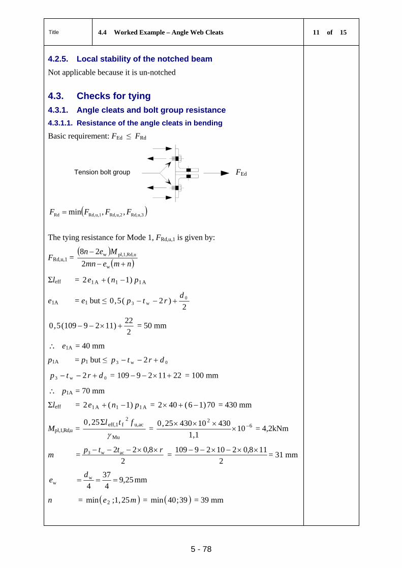
Title 4.4 Worked Example – Angle Web Cleats 11 of 15
5 - 78
4.2.5. Local stability of the notched beam
Not applicable because it is un-notched
4.3. Checks for tying
4.3.1. Angle cleats and bolt group resistance
4.3.1.1. Resistance of the angle cleats in bending
Basic requirement: FEd ≤ FRd
Tension bolt group
FEd
u,3Rd,u,2Rd,u,1Rd,Rd ,,min FFFF
The tying resistance for Mode 1, FRd,u,1 is given by:
FRd,u,1 =
nmemn
Men
w
uRd,pl,1,w
2
28
Σleff = A11A1 )1(2 pne
e1A = e1 but ≤ 2
)2(5,0 0w3
drtp
2
22)1129109(5,0 = 50 mm
e1A = 40 mm
p1A = p1 but ≤ 0w3 2 drtp
0w3 2 drtp = 221129109 = 100 mm
p1A = 70 mm
Σleff = A11A1 )1(2 pne = 70)16(402 = 430 mm
Mpl,1,Rd,u = Mu
acu,2
feff,1Σ25,0
ftl
= 62
101,1
4301043025,0
= 4,2kNm
m =2
8,022 acw3 rttp =
2
118,021029109 = 31 mm
25,94
37
4w
w d
e mm
n = me 25,1;min 2 = 39;40min = 39 mm
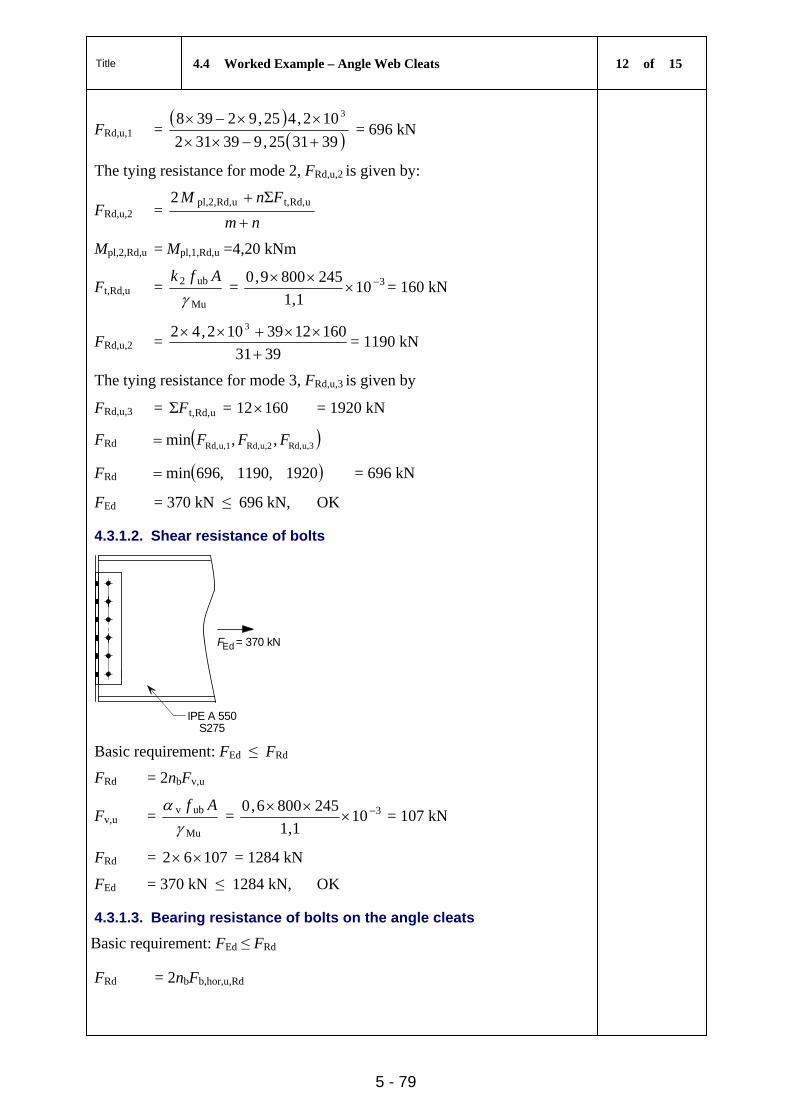
Title 4.4 Worked Example – Angle Web Cleats 12 of 15
5 - 79
FRd,u,1 =
393125,939312
102,425,92398 3
= 696 kN
The tying resistance for mode 2, FRd,u,2 is given by:
FRd,u,2 = nm
FnM
uRd,t,uRd,pl,2, Σ2
Mpl,2,Rd,u = Mpl,1,Rd,u =4,20 kNm
Ft,Rd,u = Mu
ub2
Afk
= 3101,1
2458009,0
= 160 kN
FRd,u,2 = 3931
1601239102,42 3
= 1190 kN
The tying resistance for mode 3, FRd,u,3 is given by
FRd,u,3 = uRd,t,ΣF = 16012 = 1920 kN
FRd u,3Rd,u,2Rd,u,1Rd, ,,min FFF
FRd 1920,1190,696min = 696 kN
FEd = 370 kN ≤ 696 kN, OK
4.3.1.2. Shear resistance of bolts
IPE A 550S275
Ed = 370 kNF
Basic requirement: FEd ≤ FRd
FRd = 2nbFv,u
Fv,u = Mu
ubv
Af
= 3101,1
2458006,0
= 107 kN
FRd = 10762 = 1284 kN
FEd = 370 kN ≤ 1284 kN, OK
4.3.1.3. Bearing resistance of bolts on the angle cleats
Basic requirement: FEd ≤ FRd
FRd = 2nbFb,hor,u,Rd
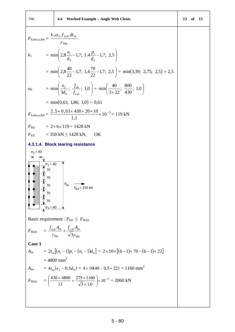
Title 4.4 Worked Example – Angle Web Cleats 13 of 15
5 - 80
Fb,hor,u,Rd = Mu
acacu,b1
dtfk
k1 =
5,2;7,14.1;7,18,2min
0
1
0
1
d
p
d
e
=
5,2;7,1
22
704,1;7,1
22
408,2min = 5,2;75,2;39,3min = 2,5
αb =
0,1;;
3min
acu,
ub
0
2
f
f
d
e =
0,1;
430
800;
223
40min
= 0,1;86,1;61,0min = 0,61
Fb,hor,u,Rd = 3101,1
102043061,05,2
= 119 kN
FRd = 11962 = 1428 kN
FEd = 350 kN ≤ 1428 kN, OK
4.3.1.4. Block tearing resistance
e
e
1
1
= 40
= 40
= 40
70
70
70
70
70
e2
hac
Ed = 370 kNF
Basic requirement : FEd ≤ FRd,b
FRd,b = M0
nvy,ac
Mu
ntu,ac
3AfAf
Case 1
Ant = 0111ac 112 dnpnt = 22167016102
= 4800 mm2
Anv = 02ac 5.04 det = 225,040104 = 1160 mm2
FRd,b = 3100,13
11602751,14800430
= 2060 kN
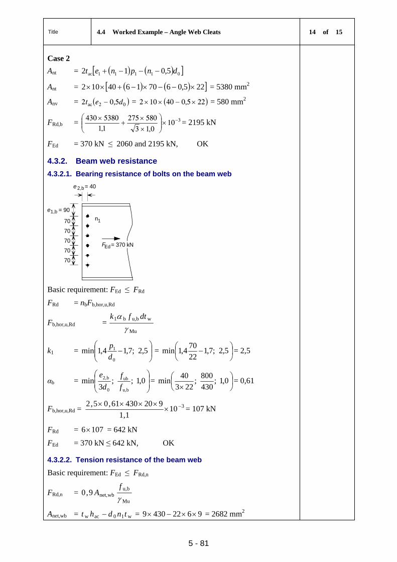
Title 4.4 Worked Example – Angle Web Cleats 14 of 15
5 - 81
Case 2
Ant = 01111ac 5,012 dnpnet
Ant = 225,06701640102 = 5380 mm2
Anv = 02ac 5,02 det = 225,040102 = 580 mm2
FRd,b = 3100,13
5802751,15380430
= 2195 kN
FEd = 370 kN ≤ 2060 and 2195 kN, OK
4.3.2. Beam web resistance
4.3.2.1. Bearing resistance of bolts on the beam web
= 90
70
70
70
70
70
e1,b
e2,b= 40
Ed= 370 kNF
1n
Basic requirement: FEd ≤ FRd
FRd = nbFb,hor,u,Rd
Fb,hor,u,Rd = Mu
wbu,b1
dtfk
k1 =
5,2;7,14,1min
0
1
d
p =
5,2;7,1
22
704,1min = 2,5
αb =
0,1;;
3min
bu,
ub
0
b2,
f
f
d
e=
0,1;
430
800;
223
40min = 0,61
Fb,hor,u,Rd = 310
1,1
92043061,05,2
= 107 kN
FRd = 1076 = 642 kN
FEd = 370 kN ≤ 642 kN, OK
4.3.2.2. Tension resistance of the beam web
Basic requirement: FEd ≤ FRd,n
FRd,n = Mu
bu,wbnet,9,0
f
A
Anet,wb = w10acw tndht = 96224309 = 2682 mm2
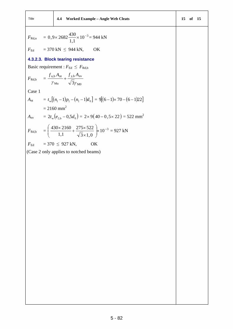
Title 4.4 Worked Example – Angle Web Cleats 15 of 15
5 - 82
FRd,n = 3101,1
43026829,0 = 944 kN
FEd = 370 kN ≤ 944 kN, OK
4.3.2.3. Block tearing resistance
Basic requirement : FEd ≤ FRd,b
FRd,b = M0
nvby,
Mu
ntbu,
3AfAf
Case 1
Ant = 0111w 11 dnpnt = 221670169
= 2160 mm2
Anv = 0b,2w 5,02 det = 225,04092 = 522 mm2
FRd,b = 3100,13
522275
1,1
2160430
= 927 kN
FEd = 370 ≤ 927 kN, OK
(Case 2 only applies to notched beams)
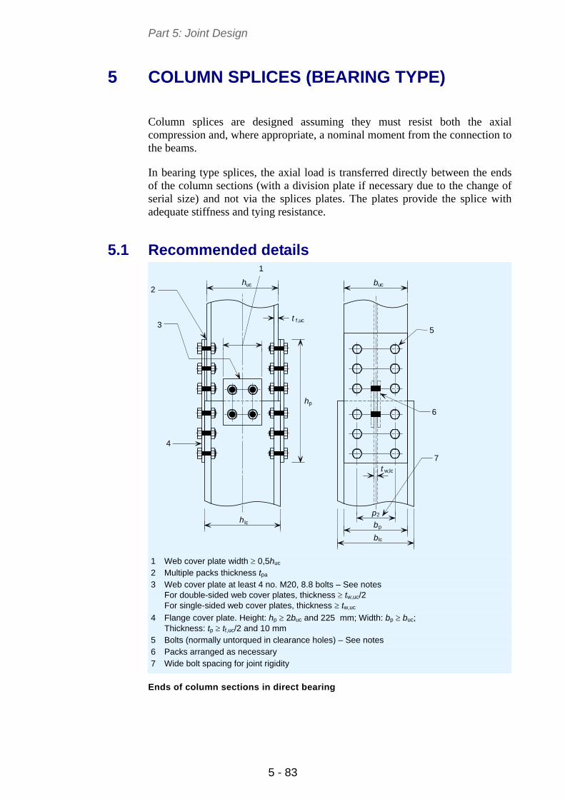
Part 5: Joint Design
5 - 83
5 COLUMN SPLICES (BEARING TYPE)
Column splices are designed assuming they must resist both the axial compression and, where appropriate, a nominal moment from the connection to the beams.
In bearing type splices, the axial load is transferred directly between the ends of the column sections (with a division plate if necessary due to the change of serial size) and not via the splices plates. The plates provide the splice with adequate stiffness and tying resistance.
5.1 Recommended details
h
h b
b
t
lc
lc
f,uc
w,lc
b
p
uc uc
t
h
2
p
p
1
2
3
4
5
6
7
1 Web cover plate width 0,5huc 2 Multiple packs thickness tpa 3 Web cover plate at least 4 no. M20, 8.8 bolts – See notes
For double-sided web cover plates, thickness tw,uc/2 For single-sided web cover plates, thickness tw,uc
4 Flange cover plate. Height: hp 2buc and 225 mm; Width: bp buc; Thickness: tp tf,uc/2 and 10 mm
5 Bolts (normally untorqued in clearance holes) – See notes 6 Packs arranged as necessary 7 Wide bolt spacing for joint rigidity
Ends of column sections in direct bearing
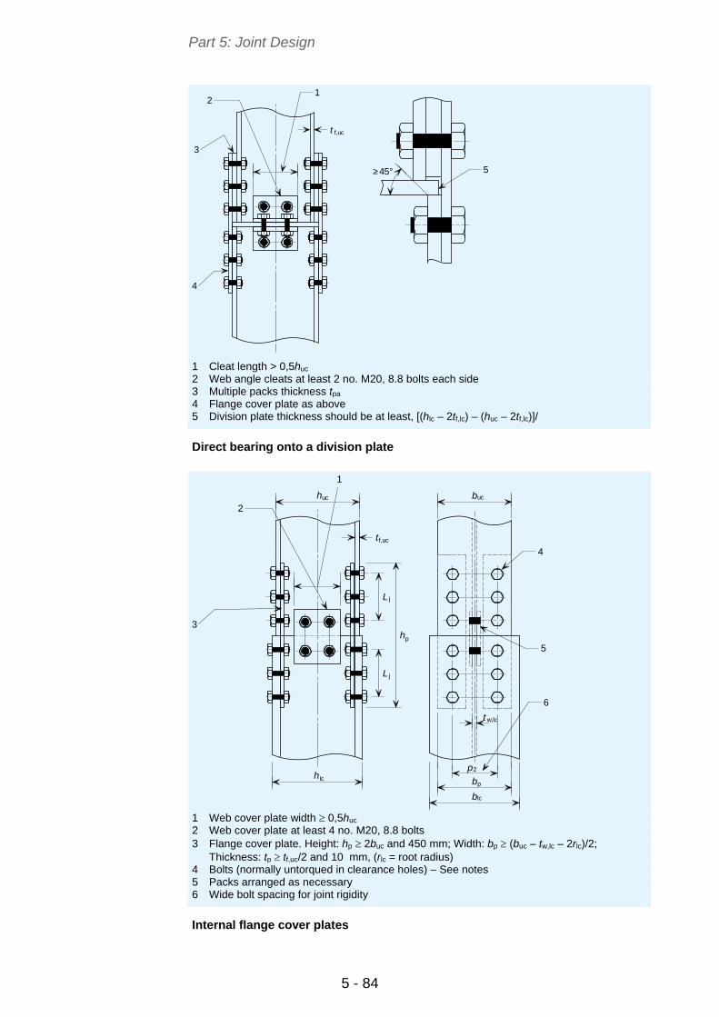
Part 5: Joint Design
5 - 84
>45°
f,uct
1
3
4
5
2
1 Cleat length > 0,5huc 2 Web angle cleats at least 2 no. M20, 8.8 bolts each side 3 Multiple packs thickness tpa 4 Flange cover plate as above 5 Division plate thickness should be at least, [(hlc – 2tf,lc) – (huc – 2tf,lc)]/
Direct bearing onto a division plate
huc
hlc
t
buc
blc
b
p
t w,lc
L
L j
j
f,uc
h
2
p
p
2
1
3
4
5
6
1 Web cover plate width 0,5huc 2 Web cover plate at least 4 no. M20, 8.8 bolts 3 Flange cover plate. Height: hp 2buc and 450 mm; Width: bp (buc – tw,lc – 2rlc)/2;
Thickness: tp tf,uc/2 and 10 mm, (rlc = root radius) 4 Bolts (normally untorqued in clearance holes) – See notes 5 Packs arranged as necessary 6 Wide bolt spacing for joint rigidity
Internal flange cover plates
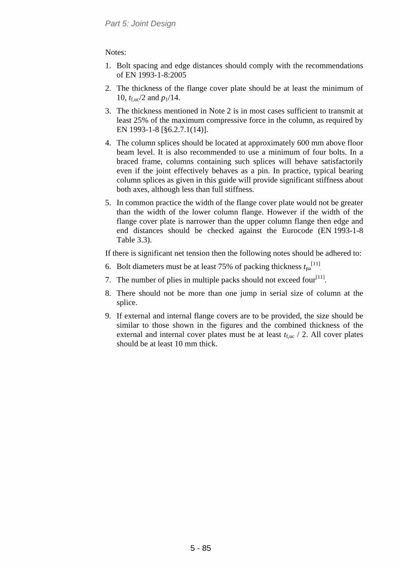
Part 5: Joint Design
5 - 85
Notes:
1. Bolt spacing and edge distances should comply with the recommendations of EN 1993-1-8:2005
2. The thickness of the flange cover plate should be at least the minimum of 10, tf,uc/2 and p1/14.
3. The thickness mentioned in Note 2 is in most cases sufficient to transmit at least 25% of the maximum compressive force in the column, as required by EN 1993-1-8 [§6.2.7.1(14)].
4. The column splices should be located at approximately 600 mm above floor beam level. It is also recommended to use a minimum of four bolts. In a braced frame, columns containing such splices will behave satisfactorily even if the joint effectively behaves as a pin. In practice, typical bearing column splices as given in this guide will provide significant stiffness about both axes, although less than full stiffness.
5. In common practice the width of the flange cover plate would not be greater than the width of the lower column flange. However if the width of the flange cover plate is narrower than the upper column flange then edge and end distances should be checked against the Eurocode (EN 1993-1-8 Table 3.3).
If there is significant net tension then the following notes should be adhered to:
6. Bolt diameters must be at least 75% of packing thickness tpa[11]
.
7. The number of plies in multiple packs should not exceed four[11].
8. There should not be more than one jump in serial size of column at the splice.
9. If external and internal flange covers are to be provided, the size should be similar to those shown in the figures and the combined thickness of the external and internal cover plates must be at least tf,uc / 2. All cover plates should be at least 10 mm thick.
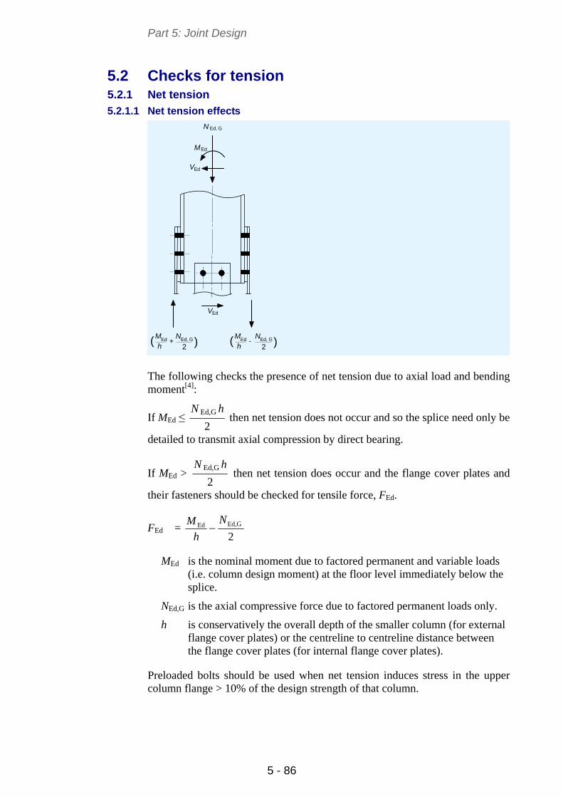
Part 5: Joint Design
5 - 86
5.2 Checks for tension 5.2.1 Net tension
5.2.1.1 Net tension effects
N Ed, G
MEd
VEd
VEd
) )( (2 2
N NEd, G Ed, GM Mh h
Ed Ed+ -
The following checks the presence of net tension due to axial load and bending moment[4]:
If MEd ≤ 2
GEd, hN then net tension does not occur and so the splice need only be
detailed to transmit axial compression by direct bearing.
If MEd > 2
GEd, hN then net tension does occur and the flange cover plates and
their fasteners should be checked for tensile force, FEd.
FEd = 2Ed,GEd
N
h
M
MEd is the nominal moment due to factored permanent and variable loads (i.e. column design moment) at the floor level immediately below the splice.
NEd,G is the axial compressive force due to factored permanent loads only.
h is conservatively the overall depth of the smaller column (for external flange cover plates) or the centreline to centreline distance between the flange cover plates (for internal flange cover plates).
Preloaded bolts should be used when net tension induces stress in the upper column flange > 10% of the design strength of that column.
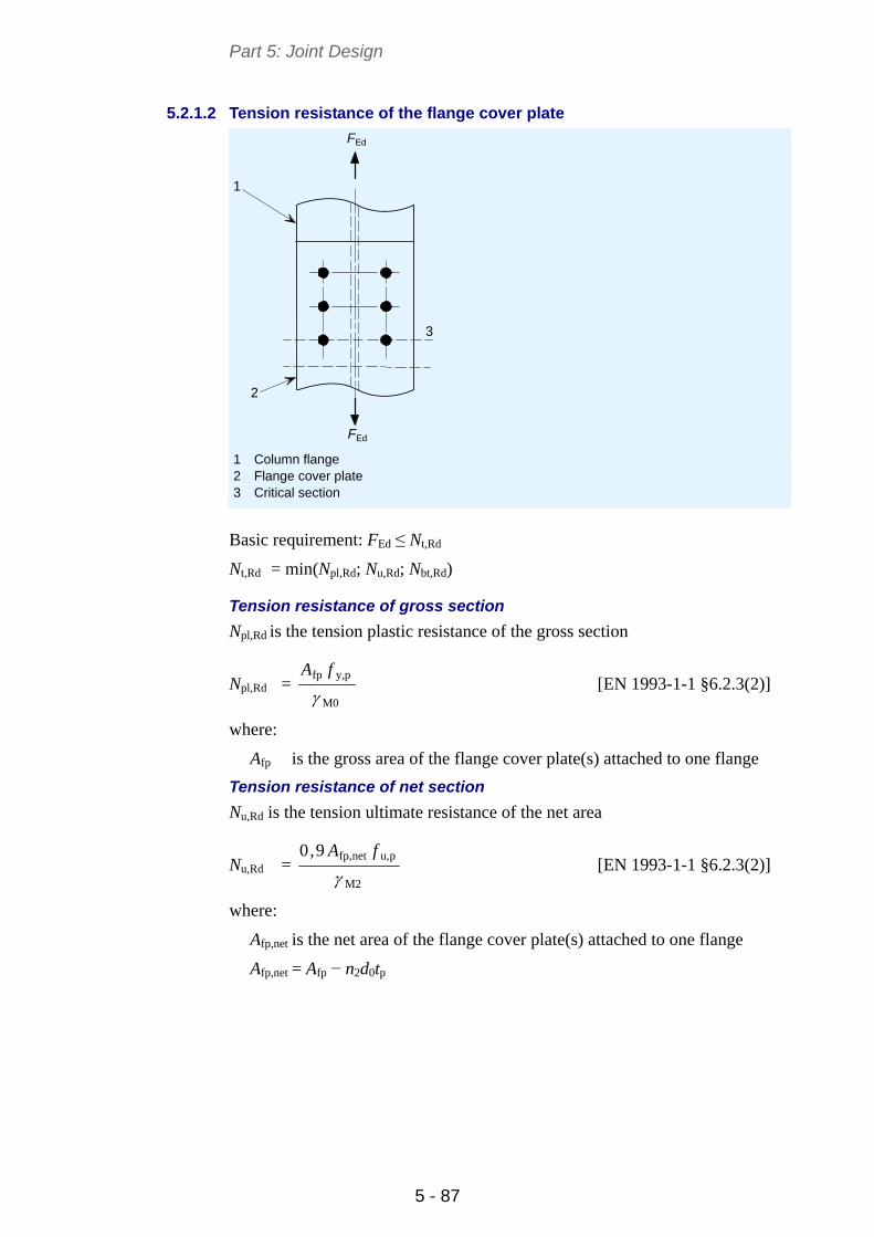
Part 5: Joint Design
5 - 87
5.2.1.2 Tension resistance of the flange cover plate
EdF
EdF
1
2
3
1 Column flange 2 Flange cover plate 3 Critical section
Basic requirement: FEd ≤ Nt,Rd
Nt,Rd = min(Npl,Rd; Nu,Rd; Nbt,Rd)
Tension resistance of gross section
Npl,Rd is the tension plastic resistance of the gross section
Npl,Rd = M0
py,fp
fA
[EN 1993-1-1 §6.2.3(2)]
where:
Afp is the gross area of the flange cover plate(s) attached to one flange
Tension resistance of net section
Nu,Rd is the tension ultimate resistance of the net area
Nu,Rd = M2
pu,netfp,9,0
fA
[EN 1993-1-1 §6.2.3(2)]
where:
Afp,net is the net area of the flange cover plate(s) attached to one flange
Afp,net = Afp − n2d0tp
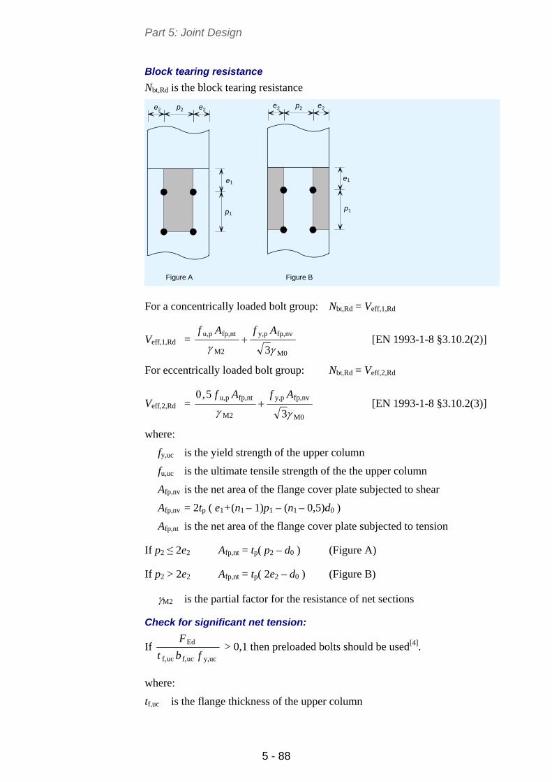
Part 5: Joint Design
5 - 88
Block tearing resistance
Nbt,Rd is the block tearing resistance
22 2
1 1
11
22 2
Figure A
e p e
e
p
e p e
p
e
Figure B
For a concentrically loaded bolt group: Nbt,Rd = Veff,1,Rd
Veff,1,Rd = M0
nvfp,py,
M2
ntfp,pu,
3AfAf
[EN 1993-1-8 §3.10.2(2)]
For eccentrically loaded bolt group: Nbt,Rd = Veff,2,Rd
Veff,2,Rd = M0
nvfp,py,
M2
ntfp,pu,
3
5,0
AfAf
[EN 1993-1-8 §3.10.2(3)]
where:
fy,uc is the yield strength of the upper column
fu,uc is the ultimate tensile strength of the the upper column
Afp,nv is the net area of the flange cover plate subjected to shear
Afp,nv = 2tp ( e1+(n1 – 1)p1 – (n1 – 0,5)d0 )
Afp,nt is the net area of the flange cover plate subjected to tension
If p2 ≤ 2e2 Afp,nt = tp( p2 – d0 ) (Figure A)
If p2 > 2e2 Afp,nt = tp( 2e2 – d0 ) (Figure B)
M2 is the partial factor for the resistance of net sections
Check for significant net tension:
If ucy,ucf,ucf,
Ed
fbt
F > 0,1 then preloaded bolts should be used[4].
where:
tf,uc is the flange thickness of the upper column
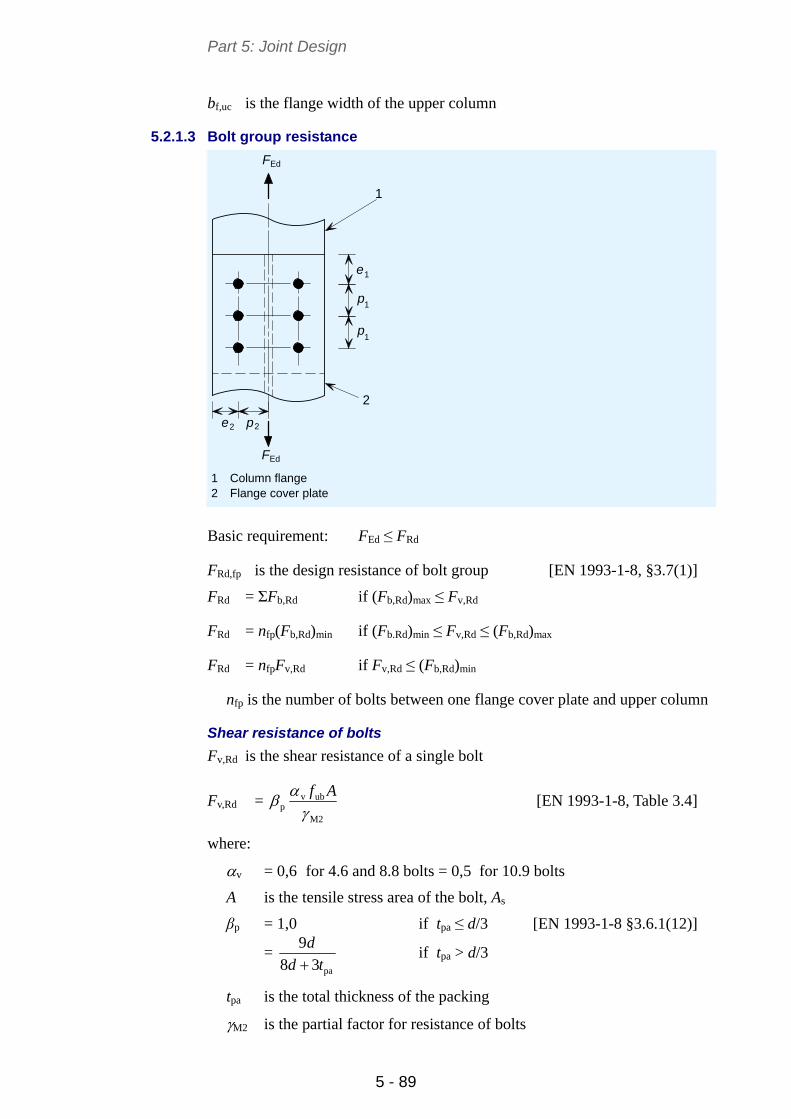
Part 5: Joint Design
5 - 89
bf,uc is the flange width of the upper column
5.2.1.3 Bolt group resistance
EdF
2 p2
EdF
e
p
p
1
1
1
e
1
2
1 Column flange 2 Flange cover plate
Basic requirement: FEd ≤ FRd
FRd,fp is the design resistance of bolt group [EN 1993-1-8, §3.7(1)]
FRd = ΣFb,Rd if (Fb,Rd)max ≤ Fv,Rd
FRd = nfp(Fb,Rd)min if (Fb.Rd)min ≤ Fv,Rd ≤ (Fb,Rd)max
FRd = nfpFv,Rd if Fv,Rd ≤ (Fb,Rd)min
nfp is the number of bolts between one flange cover plate and upper column
Shear resistance of bolts
Fv,Rd is the shear resistance of a single bolt
Fv,Rd = M2
ubvp Af
[EN 1993-1-8, Table 3.4]
where:
v = 0,6 for 4.6 and 8.8 bolts = 0,5 for 10.9 bolts
A is the tensile stress area of the bolt, As
βp = 1,0 if tpa ≤ d/3 [EN 1993-1-8 §3.6.1(12)]
= pa38
9
td
d
if tpa > d/3
tpa is the total thickness of the packing
M2 is the partial factor for resistance of bolts
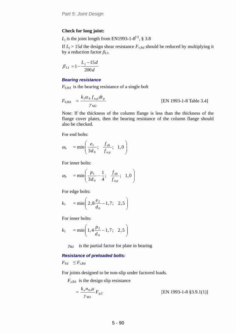
Part 5: Joint Design
5 - 90
Check for long joint:
Lj is the joint length from EN1993-1-8[1], § 3.8
If Lj > 15d the design shear resistance Fv,Rd should be reduced by multiplying it by a reduction factor βLf.
d
dL
200
151
jLf
Bearing resistance
Fb,Rd is the bearing resistance of a single bolt
Fb,Rd = M2
ppu,b1
dtfk
[EN 1993-1-8 Table 3.4]
Note: If the thickness of the column flange is less than the thickness of the flange cover plates, then the bearing resistance of the column flange should also be checked.
For end bolts:
b = min
0,1;;
3 pu,
ub
0
1
f
f
d
e
For inner bolts:
b = min
0,1;;
4
1
3 pu,
ub
0
1
f
f
d
p
For edge bolts:
k1 = min
5,2;7,18,2
0
2
d
e
For inner bolts:
k1 = min
5,2;7,14,1
0
2
d
p
M2 is the partial factor for plate in bearing
Resistance of preloaded bolts:
FEd ≤ Fs,Rd
For joints designed to be non-slip under factored loads.
Fs,Rd is the design slip resistance
= Cp,M3
fss Fnk
[EN 1993-1-8 §3.9.1(1)]
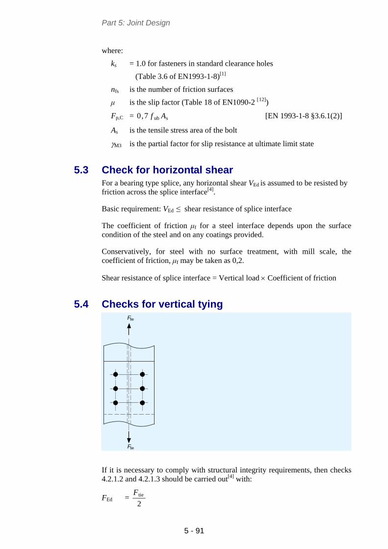
Part 5: Joint Design
5 - 91
where:
ks = 1.0 for fasteners in standard clearance holes
(Table 3.6 of EN1993-1-8)[1]
nfs is the number of friction surfaces
μ is the slip factor (Table 18 of EN1090-2 [12])
Fp,C = sub7,0 Af [EN 1993-1-8 §3.6.1(2)]
As is the tensile stress area of the bolt
M3 is the partial factor for slip resistance at ultimate limit state
5.3 Check for horizontal shear For a bearing type splice, any horizontal shear VEd is assumed to be resisted by friction across the splice interface[4].
Basic requirement: VEd ≤ shear resistance of splice interface
The coefficient of friction μf for a steel interface depends upon the surface condition of the steel and on any coatings provided.
Conservatively, for steel with no surface treatment, with mill scale, the coefficient of friction, μf may be taken as 0,2.
Shear resistance of splice interface = Vertical load Coefficient of friction
5.4 Checks for vertical tying tie
tie
F
F
If it is necessary to comply with structural integrity requirements, then checks 4.2.1.2 and 4.2.1.3 should be carried out[4] with:
FEd = 2tieF
Part 5: Joint Design
5 - 92
The yield strength should be replaced with the ultimate strength.
The partial safety factors (M0, M2) should also be replaced with the partial factor for tying resistance. (Mu = 1,1).
Note:
1. The structural integrity checks are based on the conservative assumption that the tie force is resisted by the two flange cover plates.
5. Ftie is the tensile force from EN1991-1-7, § A.6.
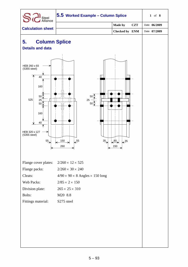
5 – 93
5.5 Worked Example – Column Splice 1 of 8
Made by CZT Date 06/2009
Calculation sheet Checked by ENM Date 07/2009
5. Column Splice Details and data
50
5025
8035 35
150
15055 55
260
525
40
160
50 25 50
160
40
HEB 320 x 127(S355 steel)
HEB 260 x 93(S355 steel)
Flange cover plates: 2/260 12 525
Flange packs: 2/260 30 240
Cleats: 4/90 90 8 Angles 150 long
Web Packs: 2/85 2 150
Division plate: 265 25 310
Bolts: M20 8.8
Fittings material: S275 steel
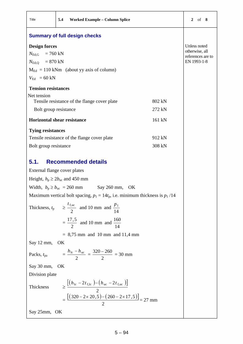
Title 5.4 Worked Example – Column Splice 2 of 8
5 – 94
Summary of full design checks
Design forces
NEd,G = 760 kN
NEd,Q = 870 kN
MEd = 110 kNm (about yy axis of column)
VEd = 60 kN
Unless noted otherwise, all references are to EN 1993-1-8
Tension resistances
Net tension Tensile resistance of the flange cover plate 802 kN
Bolt group resistance 272 kN
Horizontal shear resistance 161 kN
Tying resistances
Tensile resistance of the flange cover plate 912 kN
Bolt group resistance 308 kN
5.1. Recommended details
External flange cover plates
Height, hp 2buc and 450 mm
Width, bp buc = 260 mm Say 260 mm, OK
Maximum vertical bolt spacing, p1 = 14tp, i.e. minimum thickness is p1 /14
Thickness, tp 2
ucf,t and 10 mm and
141p
= 2
5,17 and 10 mm and
14
160
= 8,75 mm and 10 mm and 11,4 mm
Say 12 mm, OK
Packs, tpa = 2
uclc hh =
2
260320 = 30 mm
Say 30 mm, OK
Division plate
Thickness
2
22 ucf,uclcf,lc thth
=
2
5,1722605,202320 = 27 mm
Say 25mm, OK
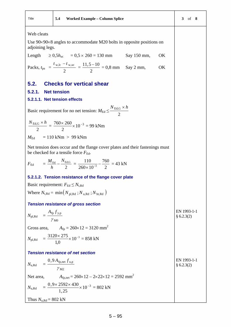
Title 5.4 Worked Example – Column Splice 3 of 8
5 – 95
Web cleats
Use 90908 angles to accommodate M20 bolts in opposite positions on adjoining legs.
Length 0,5huc = 0,5 260 = 130 mm Say 150 mm, OK
Packs, tpa = 2
ucw,lcw, tt =
2
105,11 = 0,8 mm Say 2 mm, OK
5.2. Checks for vertical shear
5.2.1. Net tension
5.2.1.1. Net tension effects
Basic requirement for no net tension: MEd ≤2GEd, hN
2GEd, hN
= 3102
260760
= 99 kNm
MEd = 110 kNm > 99 kNm
Net tension does occur and the flange cover plates and their fastenings must be checked for a tensile force FEd.
FEd = 2Ed,GEd
N
h
M =
2
760
10260
1103 = 43 kN
5.2.1.2. Tension resistance of the flange cover plate
Basic requirement: FEd ≤ Nt,Rd
Where Nt,Rd = Rdbt,Rdu,Rdpl, ;;min NNN
Tension resistance of gross section
Npl,Rd = M0
py,fp
fA
EN 1993-1-1 § 6.2.3(2)
Gross area, Afp = 26012 = 3120 mm2
Npl,Rd = 3100,1
2753120
= 858 kN
Tension resistance of net section
Nu,Rd = M2
pu,netfp,9,0
fA
EN 1993-1-1 § 6.2.3(2)
Net area, Afp,net = 26012 – 22212 = 2592 mm2
Nu,Rd = 31025,1
43025929,0
= 802 kN
Thus Nu,Rd = 802 kN
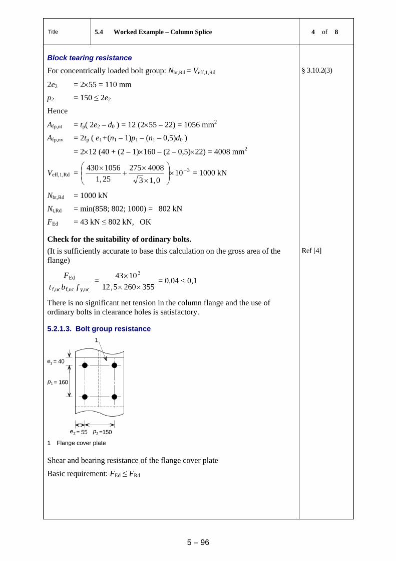
Title 5.4 Worked Example – Column Splice 4 of 8
5 – 96
Block tearing resistance
For concentrically loaded bolt group: Nbt,Rd = Veff,1,Rd § 3.10.2(3)
2e2 = 255 = 110 mm
p2 = 150 ≤ 2e2
Hence
Afp,nt = tp( 2e2 – d0 ) = 12 (255 – 22) = 1056 mm2
Afp,nv = 2tp ( e1+(n1 – 1)p1 – (n1 – 0,5)d0 )
= 212 (40 + (2 – 1)160 – (2 – 0,5)22) = 4008 mm2
Veff,1,Rd = 3100,13
4008275
25,1
1056430
= 1000 kN
Nbt,Rd = 1000 kN
Nt,Rd = min(858; 802; 1000) = 802 kN
FEd = 43 kN ≤ 802 kN, OK
Check for the suitability of ordinary bolts.
(It is sufficiently accurate to base this calculation on the gross area of the flange)
Ref [4]
ucy,ucf,ucf,
Ed
fbt
F =
3552605,12
1043 3
= 0,04 < 0,1
There is no significant net tension in the column flange and the use of ordinary bolts in clearance holes is satisfactory.
5.2.1.3. Bolt group resistance
= 40 1
1
2
e
= 160p
2pe =150= 55
1
1 Flange cover plate
Shear and bearing resistance of the flange cover plate
Basic requirement: FEd ≤ FRd
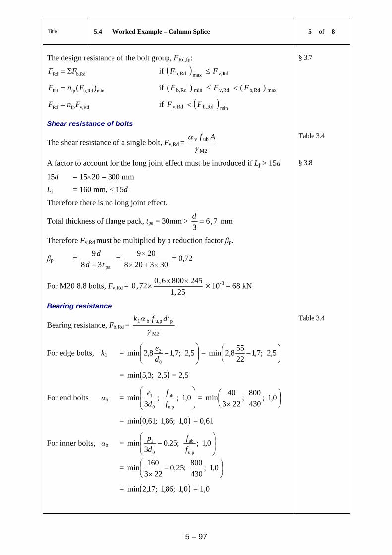
Title 5.4 Worked Example – Column Splice 5 of 8
5 – 97
The design resistance of the bolt group, FRd,fp:
Rdb,Rd ΣFF if Rdv,maxRdb, FF
minRdb,fpRd )(FnF if maxRdb,Rdv,minRdb, )()( FFF
Rdv,fpRd FnF if minRdb,Rdv, FF
§ 3.7
Shear resistance of bolts
The shear resistance of a single bolt, Fv,Rd = M2
ubv
Af
Table 3.4
A factor to account for the long joint effect must be introduced if Lj > 15d § 3.8
15d = 1520 = 300 mm
Lj = 160 mm, < 15d
Therefore there is no long joint effect.
Total thickness of flange pack, tpa = 30mm > 7,63
d mm
Therefore Fv,Rd must be multiplied by a reduction factor βp.
βp = pa38
9
td
d
=
303208
209
= 0,72
For M20 8.8 bolts, Fv,Rd = 25,1
2458006,072,0
×10-3 = 68 kN
Bearing resistance
Bearing resistance, Fb,Rd = M2
ppu,b1
dtfk
Table 3.4
For edge bolts, k1 =
5,2;7,18,2min
0
2
d
e =
5,2;7,1
22
558,2min
= 5,2;3,5min = 2,5
For end bolts αb =
0,1;;
3min
pu,
ub
0
1
f
f
d
e =
0,1;
430
800;
223
40min
= 0,1;86,1;61,0min = 0,61
For inner bolts, αb =
0,1;;25,0
3min
pu,
ub
0
1
f
f
d
p
=
0,1;
430
800;25,0
223
160min
= 0,1;86,1;17,2min = 1,0
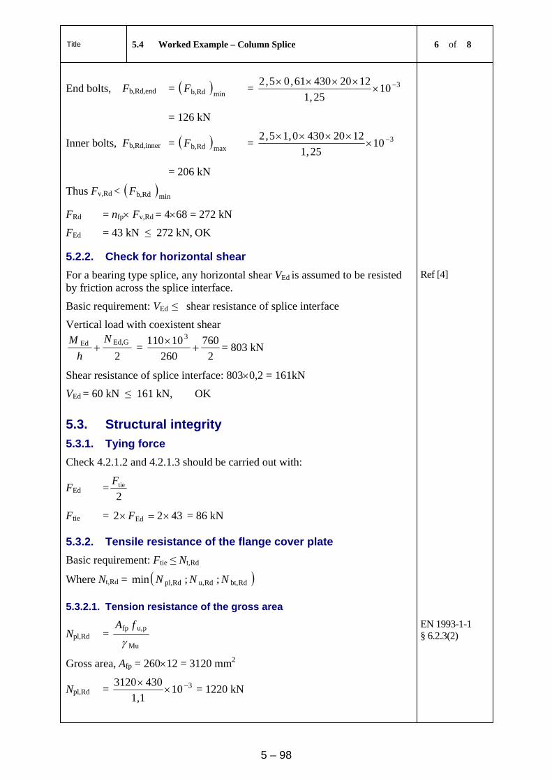
Title 5.4 Worked Example – Column Splice 6 of 8
5 – 98
End bolts, Fb,Rd,end = minRdb,F = 310
25,1
122043061,05,2
= 126 kN
Inner bolts, Fb,Rd,inner = maxRdb,F = 310
25,1
12204300,15,2
= 206 kN
Thus Fv,Rd < minRdb,F
FRd = nfp Fv,Rd = 468 = 272 kN
FEd = 43 kN ≤ 272 kN, OK
5.2.2. Check for horizontal shear
For a bearing type splice, any horizontal shear VEd is assumed to be resisted by friction across the splice interface.
Ref [4]
Basic requirement: VEd ≤ shear resistance of splice interface
Vertical load with coexistent shear
2GEd,Ed N
h
M =
2
760
260
10110 3
= 803 kN
Shear resistance of splice interface: 8030,2 = 161kN
VEd = 60 kN ≤ 161 kN, OK
5.3. Structural integrity
5.3.1. Tying force
Check 4.2.1.2 and 4.2.1.3 should be carried out with:
FEd =2tieF
Ftie = 4322 Ed F = 86 kN
5.3.2. Tensile resistance of the flange cover plate
Basic requirement: Ftie ≤ Nt,Rd
Where Nt,Rd = Rdbt,Rdu,Rdpl, ;;min NNN
5.3.2.1. Tension resistance of the gross area
Npl,Rd = Mu
pu,fp
fA
EN 1993-1-1 § 6.2.3(2)
Gross area, Afp = 26012 = 3120 mm2
Npl,Rd = 3101,1
4303120
= 1220 kN
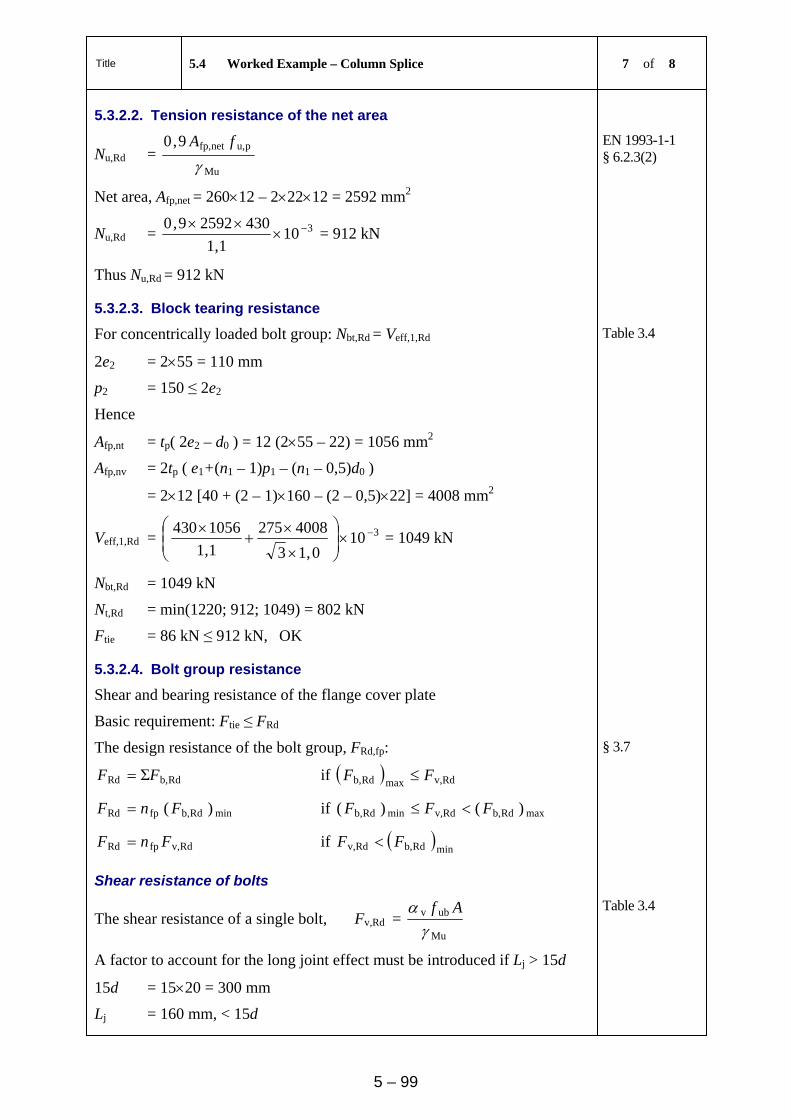
Title 5.4 Worked Example – Column Splice 7 of 8
5 – 99
5.3.2.2. Tension resistance of the net area
Nu,Rd = Mu
pu,netfp,9,0
fA
EN 1993-1-1 § 6.2.3(2)
Net area, Afp,net = 26012 – 22212 = 2592 mm2
Nu,Rd = 3101,1
43025929,0
= 912 kN
Thus Nu,Rd = 912 kN
5.3.2.3. Block tearing resistance
For concentrically loaded bolt group: Nbt,Rd = Veff,1,Rd Table 3.4
2e2 = 255 = 110 mm
p2 = 150 ≤ 2e2
Hence
Afp,nt = tp( 2e2 – d0 ) = 12 (255 – 22) = 1056 mm2
Afp,nv = 2tp ( e1+(n1 – 1)p1 – (n1 – 0,5)d0 )
= 212 [40 + (2 – 1)160 – (2 – 0,5)22] = 4008 mm2
Veff,1,Rd = 3100,13
4008275
1,1
1056430
= 1049 kN
Nbt,Rd = 1049 kN
Nt,Rd = min(1220; 912; 1049) = 802 kN
Ftie = 86 kN ≤ 912 kN, OK
5.3.2.4. Bolt group resistance
Shear and bearing resistance of the flange cover plate
Basic requirement: Ftie ≤ FRd
The design resistance of the bolt group, FRd,fp:
Rdb,Rd ΣFF if Rdv,maxRdb, FF
minRdb,fpRd )( FnF if maxRdb,Rdv,minRdb, )()( FFF
Rdv,fpRd FnF if minRdb,Rdv, FF
§ 3.7
Shear resistance of bolts
The shear resistance of a single bolt, Fv,Rd = Mu
ubv
Af
Table 3.4
A factor to account for the long joint effect must be introduced if Lj > 15d
15d = 1520 = 300 mm
Lj = 160 mm, < 15d
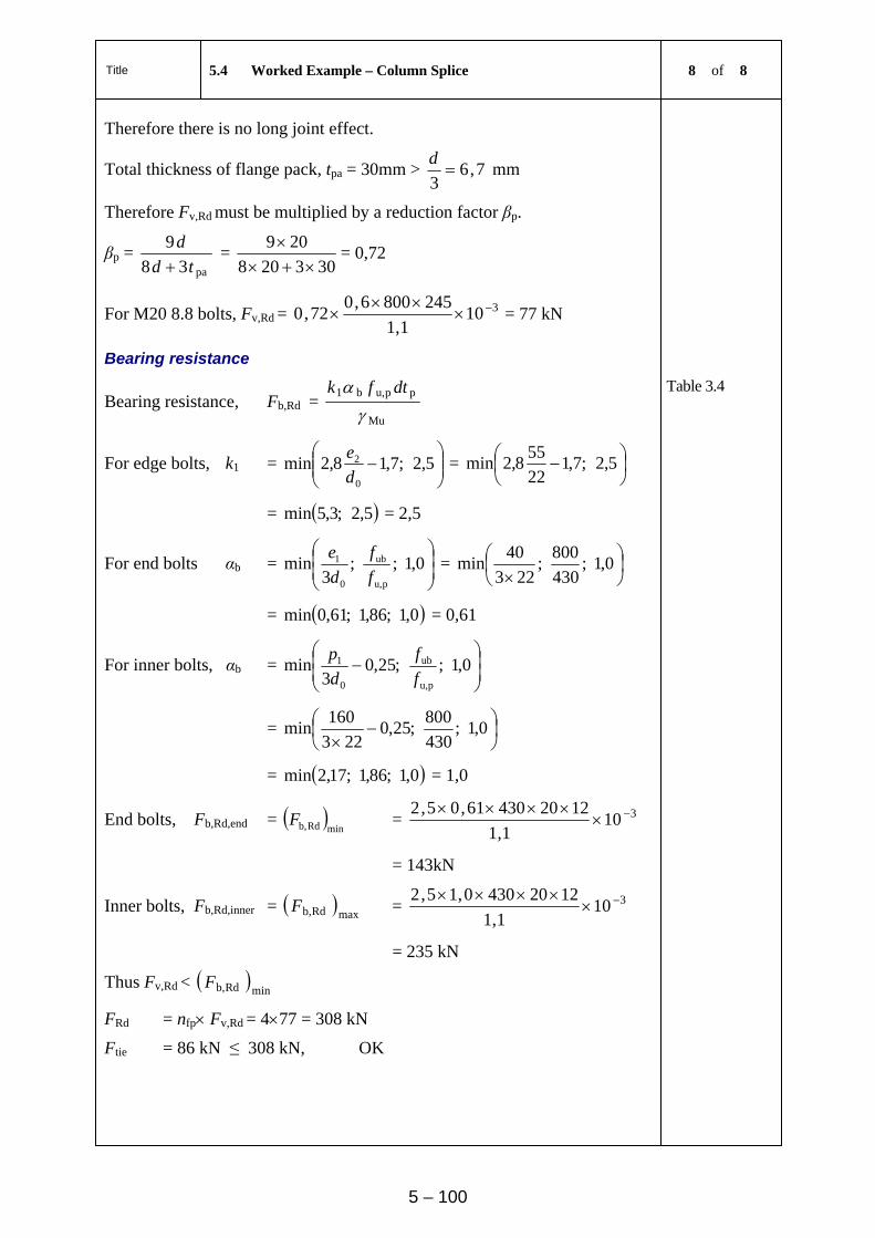
Title 5.4 Worked Example – Column Splice 8 of 8
5 – 100
Therefore there is no long joint effect.
Total thickness of flange pack, tpa = 30mm > 7,63
d mm
Therefore Fv,Rd must be multiplied by a reduction factor βp.
βp = pa38
9
td
d
=
303208
209
= 0,72
For M20 8.8 bolts, Fv,Rd = 3101,1
2458006,072,0
= 77 kN
Bearing resistance
Bearing resistance, Fb,Rd = Mu
ppu,b1
dtfk
Table 3.4
For edge bolts, k1 =
5,2;7,18,2min
0
2
d
e =
5,2;7,1
22
558,2min
= 5,2;3,5min = 2,5
For end bolts αb =
0,1;;
3min
pu,
ub
0
1
f
f
d
e =
0,1;
430
800;
223
40min
= 0,1;86,1;61,0min = 0,61
For inner bolts, αb =
0,1;;25,0
3min
pu,
ub
0
1
f
f
d
p
=
0,1;
430
800;25,0
223
160min
= 0,1;86,1;17,2min = 1,0
End bolts, Fb,Rd,end = minRdb,F = 310
1,1
122043061,05,2
= 143kN
Inner bolts, Fb,Rd,inner = maxRdb,F = 310
1,1
12204300,15,2
= 235 kN
Thus Fv,Rd < minRdb,F
FRd = nfp Fv,Rd = 477 = 308 kN
Ftie = 86 kN ≤ 308 kN, OK
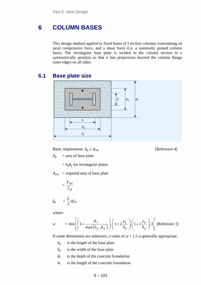
Part 5: Joint Design
5 – 101
6 COLUMN BASES
This design method applied to fixed bases of I section columns transmitting an axial compressive force, and a shear force (i.e. a nominally pinned column base). The rectangular base plate is welded to the column section in a symmetrically position so that it has projections beyond the column flange outer edges on all sides.
6.1 Base plate size
p
f
b bp fb
h
h
h
Basic requirement: Ap Areq [Reference 4]
Ap = area of base plate
= hpbp for rectangular plates
Areq = required area of base plate
= jd
Ed
f
F
fjd = 3
2 fcd
where:
= ,,max
1minpp
f
bh
d
3,21,21
p
b
p
h
b
e
h
e [Reference 3]
If some dimensions are unknown, a value of = 1,5 is generally appropriate.
hp is the length of the base plate
bp is the width of the base plate
df is the depth of the concrete foundation
hf is the length of the concrete foundation
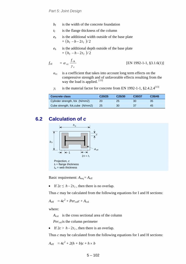
Part 5: Joint Design
5 – 102
bf is the width of the concrete foundation
tf is the flange thickness of the column
eb is the additional width outside of the base plate = 2/2 ff tbb
eh is the additional depth outside of the base plate = 2/2 ff thh
fcd = c
ckcc
f
[EN 1992-1-1, §3.1.6(1)]
αcc is a coefficient that takes into account long term effects on the compressive strength and of unfavorable effects resulting from the way the load is applied. [13]
c is the material factor for concrete from EN 1992-1-1, §2.4.2.4[13]
Concrete class C20/25 C25/30 C30/37 C35/45
Cylinder strength, fck (N/mm2) 20 25 30 35
Cube strength, fck,cube (N/mm2) 25 30 37 45
6.2 Calculation of c
eff
p
p
h
b
2 + c t f
A
c
1
Projection, c
tf = flange thickness tw = web thickness
Basic requirement: Areq = Aeff
If 2c ≤ f2 th , then there is no overlap.
Thus c may be calculated from the following equations for I and H sections:
Aeff ≈ 4c2 + Percolc + Acol
where:
Acol is the cross sectional area of the column
Percol is the column perimeter
If 2c > f2 th , then there is an overlap.
Thus c may be calculated from the following equations for I and H sections:
Aeff ≈ 4c2 + 2(h + b)c + h b
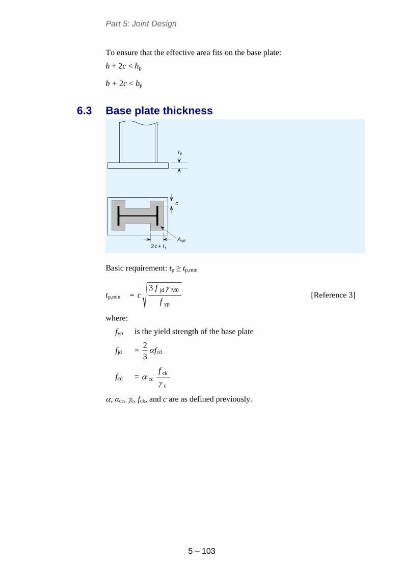
Part 5: Joint Design
5 – 103
To ensure that the effective area fits on the base plate:
h + 2c < hp
b + 2c < bp
6.3 Base plate thickness
eff
p
2 + c t f
A
c
t
Basic requirement: tp ≥ tp,min
tp,min = yp
M0jd3
f
fc
[Reference 3]
where:
fyp is the yield strength of the base plate
fjd = 3
2 fcd
fcd = c
ckcc
f
, αcc, c, fck, and c are as defined previously.
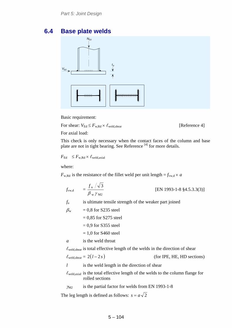
Part 5: Joint Design
5 – 104
6.4 Base plate welds NEd
VEd
tp
Basic requirement:
For shear: VEd Fw,Rd ℓweld,shear [Reference 4]
For axial load:
This check is only necessary when the contact faces of the column and base plate are not in tight bearing. See Reference [4] for more details.
FEd Fw,Rd ℓweld,axial
where:
Fw,Rd is the resistance of the fillet weld per unit length = fvw,d a
fvw,d = M2w
u 3
f
[EN 1993-1-8 §4.5.3.3(3)]
fu is ultimate tensile strength of the weaker part joined
w = 0,8 for S235 steel
= 0,85 for S275 steel
= 0,9 for S355 steel
= 1,0 for S460 steel
a is the weld throat
ℓweld,shear is total effective length of the welds in the direction of shear
ℓweld,shear = sl 22 (for IPE, HE, HD sections)
l is the weld length in the direction of shear
ℓweld,axial is the total effective length of the welds to the column flange for rolled sections
M2 is the partial factor for welds from EN 1993-1-8
The leg length is defined as follows: 2as
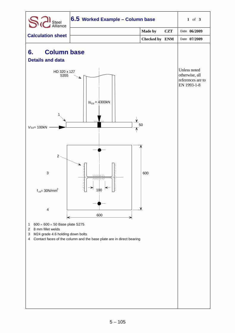
5 – 105
6.5 Worked Example – Column base 1 of 3
Made by CZT Date 06/2009
Calculation sheet Checked by ENM Date 07/2009
6. Column base Details and data
600
1002
50
f = 30N/mm
600
EdN = 4300kN
= 100kNEdV
ck
1
2
3
4
HD 320 x 127S355
1 600 600 50 Base plate S275 2 8 mm fillet welds 3 M24 grade 4.6 holding down bolts 4 Contact faces of the column and the base plate are in direct bearing
Unless noted otherwise, all references are to EN 1993-1-8
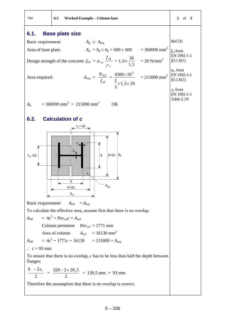
Title 6.5 Worked Example – Column base 2 of 3
5 – 106
6.1. Base plate size
Basic requirement: Ap Areq
Area of base plate: Ap = hp bp = 600 600 = 360000 mm2
Design strength of the concrete: fcd = c
ckcc
f
= 5,1
300,1 = 20 N/mm2
Area required: Areq = jd
Ed
f
N =
205,13
2104300 3
= 215000 mm2
Ref [3] fcd from EN 1992-1-1 §3.1.6(1) αcc from EN 1992-1-1 §3.1.6(1) C from EN 1992-1-1 Table 2.1N
Ap = 360000 mm2 > 215000 mm2 OK
6.2. Calculation of c
Aeff
p
f + 2t c
b +2 bp
h
+2
h
tf
tw t w +2c
h c
b c
Basic requirement: Aeff = Areq
To calculate the effective area, assume first that there is no overlap.
Aeff ≈ 4c2 + Percolc + Acol
Column perimeter Percol = 1771 mm
Area of column Acol = 16130 mm2
Aeff ≈ 4c2 + 1771c + 16130 = 215000 = Areq
c = 93 mm
To ensure that there is no overlap, c has to be less than half the depth between flanges:
2
2 fth =
2
5,202320 = 139,5 mm > 93 mm
Therefore the assumption that there is no overlap is correct.
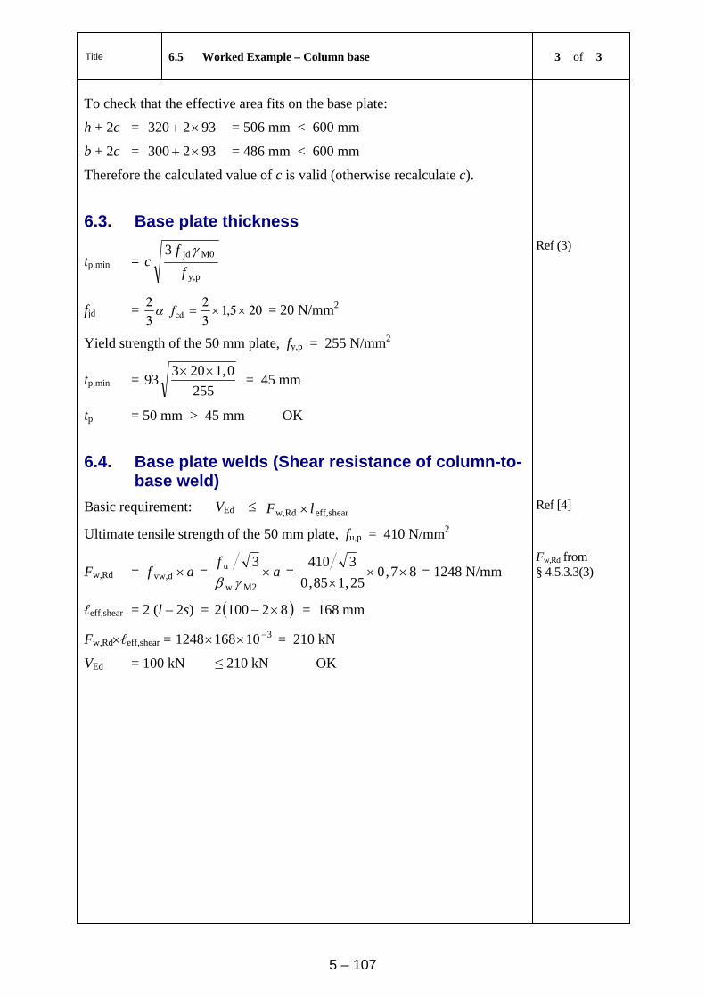
Title 6.5 Worked Example – Column base 3 of 3
5 – 107
To check that the effective area fits on the base plate:
h + 2c = 932320 = 506 mm < 600 mm
b + 2c = 932300 = 486 mm < 600 mm
Therefore the calculated value of c is valid (otherwise recalculate c).
6.3. Base plate thickness
tp,min = py,
M0jd3
f
fc
Ref (3)
fjd = 205,132
32
cd f = 20 N/mm2
Yield strength of the 50 mm plate, fy,p = 255 N/mm2
tp,min = 255
0,120393
= 45 mm
tp = 50 mm > 45 mm OK
6.4. Base plate welds (Shear resistance of column-to-base weld)
Basic requirement: VEd eff,shearRdw, lF Ref [4]
Ultimate tensile strength of the 50 mm plate, fu,p = 410 N/mm2
Fw,Rd = af dvw, = af
M2w
u 3
= 87,0
25,185,0
3410
= 1248 N/mm
ℓeff,shear = 2 (l – 2s) = 821002 = 168 mm
Fw,Rdℓeff,shear = 3101681248 = 210 kN
Fw,Rd from § 4.5.3.3(3)
VEd = 100 kN ≤ 210 kN OK
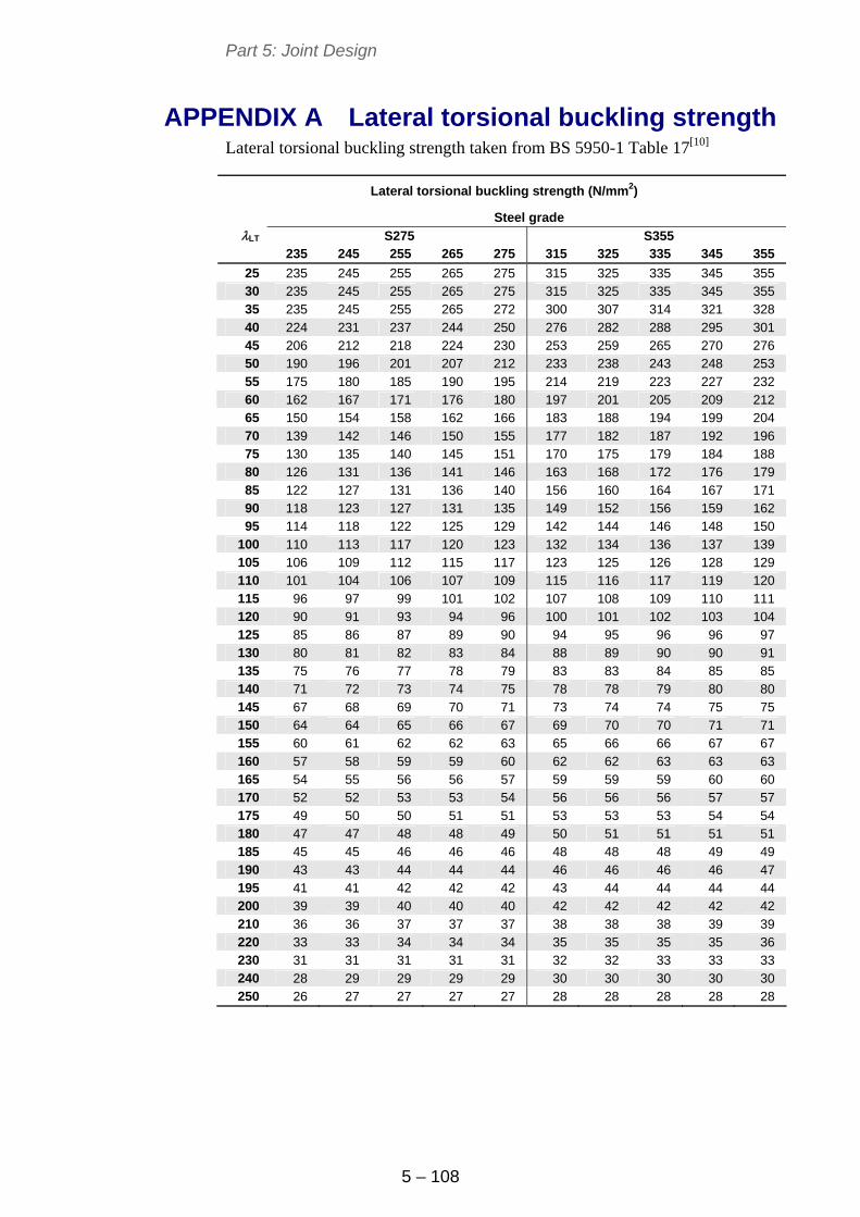
Part 5: Joint Design
5 – 108
APPENDIX A Lateral torsional buckling strength Lateral torsional buckling strength taken from BS 5950-1 Table 17[10]
Lateral torsional buckling strength (N/mm2)
Steel grade LT S275 S355
235 245 255 265 275 315 325 335 345 355
25 235 245 255 265 275 315 325 335 345 355 30 235 245 255 265 275 315 325 335 345 355 35 235 245 255 265 272 300 307 314 321 328 40 224 231 237 244 250 276 282 288 295 301 45 206 212 218 224 230 253 259 265 270 276 50 190 196 201 207 212 233 238 243 248 253 55 175 180 185 190 195 214 219 223 227 232 60 162 167 171 176 180 197 201 205 209 212 65 150 154 158 162 166 183 188 194 199 204 70 139 142 146 150 155 177 182 187 192 196 75 130 135 140 145 151 170 175 179 184 188 80 126 131 136 141 146 163 168 172 176 179 85 122 127 131 136 140 156 160 164 167 171 90 118 123 127 131 135 149 152 156 159 162 95 114 118 122 125 129 142 144 146 148 150
100 110 113 117 120 123 132 134 136 137 139 105 106 109 112 115 117 123 125 126 128 129 110 101 104 106 107 109 115 116 117 119 120 115 96 97 99 101 102 107 108 109 110 111 120 90 91 93 94 96 100 101 102 103 104 125 85 86 87 89 90 94 95 96 96 97 130 80 81 82 83 84 88 89 90 90 91 135 75 76 77 78 79 83 83 84 85 85 140 71 72 73 74 75 78 78 79 80 80 145 67 68 69 70 71 73 74 74 75 75 150 64 64 65 66 67 69 70 70 71 71 155 60 61 62 62 63 65 66 66 67 67 160 57 58 59 59 60 62 62 63 63 63 165 54 55 56 56 57 59 59 59 60 60 170 52 52 53 53 54 56 56 56 57 57 175 49 50 50 51 51 53 53 53 54 54 180 47 47 48 48 49 50 51 51 51 51 185 45 45 46 46 46 48 48 48 49 49 190 43 43 44 44 44 46 46 46 46 47 195 41 41 42 42 42 43 44 44 44 44 200 39 39 40 40 40 42 42 42 42 42 210 36 36 37 37 37 38 38 38 39 39 220 33 33 34 34 34 35 35 35 35 36 230 31 31 31 31 31 32 32 33 33 33 240 28 29 29 29 29 30 30 30 30 30 250 26 27 27 27 27 28 28 28 28 28
Part 5: Joint Design
5 – 109
REFERENCES
1 EN 1993-1-8:2005: Eurocode 3 Design of steel structures. Design of joints
2 EN 1991-1-7: 2006: Eurocode 1 Actions on structures. General actions. Accidental actions
3 Detailed European design guides to the Eurocode. (http://www.access-steel.com)
4 Joints in steel construction: Simple connections Steel Construction Institute, 2002
5 CHENG, J. J. R. and YURA, J. A. Journal of the Structural Division, ASCE, October 1986 Local web buckling of coped beams
6 CHENG, J. J. R, YURA, J. A. and JOHNSON. C. P. Department of Civil Engineering, University of Texas at Austin Design and behaviour of coped beams PMFSEL Report No. 841, July 1984
7 JARRETT, N. D. Tests on beam/column web side plate connections BRE Client Report CR 54/90 Building Research Establishment, Watford, September 1990.
8 JASPART, J.-P., DEMONCEAU, J.-F.,.RENKIN, S., and GUILLAUME, M. L. European recommendation for the design of simple joints in steel structures Publication n°126, First edition, ECCS, 2009
9 RENKIN, S. Development of a European process for the design of simple structural joint in steel frames (in French): Diploma work, University of Liege, June 2003.
10 BS 5950-1:2000 Structural use of steelwork in building. Code of practice for design. Rolled and welded sections BSI, 2000
11 YURA, J. A., HANSEN, M. A. and FRANK, K. H. Bolted splice connections with undeveloped fillers Journal of the Structural Division ASCE, December 1982
12 EN 1090-2:2008: Execution of steel structures and aluminium structures. Technical requirements for the execution of steel structures
13 EN 1992-1-1:2004: Eurocode 2 Design of concrete structures. General rules and rules for buildings
Flow charts Flow charts for End plate, Fin plate and Column bases are available on the Access Steel web site (http://www.access-steel.com)
The document references for these joint types are as follows:
Partial depth end plate SF008a
Fin plate SF009a
Column bases SF010a
STEEL BUILDINGS IN EUROPE
Multi-Storey Steel Buildings
Part 6: Fire Engineering
.

Multi-Storey Steel Buildings
Part 6: Fire Engineering

6 - ii
Part 6: Fire Engineering
6 - iii
FOREWORD
This publication is the sixth part of a design guide, Multi-Storey Steel Buildings.
The 10 parts in the Multi-Storey Steel Buildings guide are:
Part 1: Architect’s guide
Part 2: Concept design
Part 3: Actions
Part 4: Detailed design
Part 5: Joint design
Part 6: Fire Engineering
Part 7: Model construction specification
Part 8: Design software – section capacity
Part 9: Design software – simple connections
Part 10: Software specification for composite beams.
Multi-Storey Steel Buildings is one of two design guides. The second design guide is Single-Storey Steel Buildings.
The two design guides have been produced in the framework of the European project “Facilitating the market development for sections in industrial halls and low rise buildings (SECHALO) RFS2-CT-2008-0030”.
The design guides have been prepared under the direction of Arcelor Mittal, Peiner Träger and Corus. The technical content has been prepared by CTICM and SCI, collaborating as the Steel Alliance.

Part 6: Fire Engineering
6 - iv
Part 6: Fire Engineering
6 - v
Contents
Page No
FOREWORD iii
SUMMARY vi
1 INTRODUCTION 1
2 FIRE SAFETY ENGINEERING 3 2.1 Definition of fire safety engineering 3 2.2 Objectives of fire safety 3 2.3 Approaches to structural fire engineering 5
3 FIRE PROTECTION SOLUTIONS 14 3.1 Active fire protection 14 3.2 Passive fire protection 15 3.3 Fire resisting construction 19
4 SIMPLE CALCULATION MODELS 26 4.1 Fire behaviour and thermal actions 26 4.2 Heat transfer 29 4.3 Structural Analysis 30 4.4 Simple structural fire design methods 31
5 TENSILE MEMBRANE ACTION 37 5.1 Cardington fire test 37 5.2 FRACOF fire tests 39
6 USE OF NATURAL FIRE EXPOSURE AND ADVANCED STRUCTURAL MODELLING 42 6.1 General 42 6.2 Modelling fire severity 42 6.3 Modelling heat transfer 43 6.4 Advanced structural models 43 6.5 Validation/verification of advanced models 44 6.6 Regulatory approval 44
REFERENCES 45
FURTHER READING 45
Worked Example: Fire safety strategies and design approach of steel floor beam 49
Part 6: Fire Engineering
6 - vi
SUMMARY
This publication provides engineers with a wide range of strategies and design approaches for the fire safety design of multi-storey buildings. It contains background information and the design basis of fire safety engineering. Forms of construction covered in this publication include unprotected and protected steel members and composite members. In terms of fire safety strategies the reader will find guidance on active and passive fire protection as well as alternative structural solutions and structural fire design.
Three different fire design approaches are covered in this guide:
Use of established datasheets.
Simple calculation models to EN 1993-1-2 and EN 1994-1-2.
Advanced calculation models.
Engineers may use pre-engineered datasheets to ensure the fire safety of multi-storey buildings. More economic fire design solutions may be achieved by using the simple calculation models given in EN 1993-1-2 and EN 1994-1-2 or by carrying out advanced analyses based on engineering fundamentals and finite element techniques. The latter approach is generally applied by specialist fire engineers.
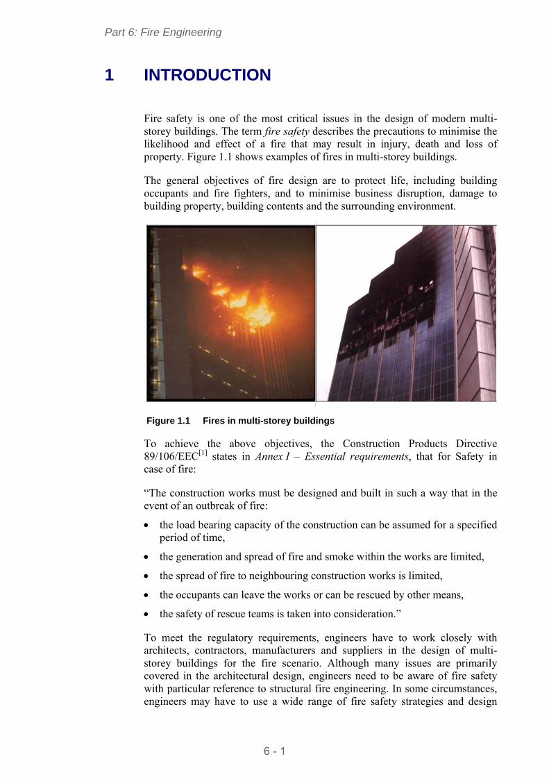
Part 6: Fire Engineering
6 - 1
1 INTRODUCTION
Fire safety is one of the most critical issues in the design of modern multi-storey buildings. The term fire safety describes the precautions to minimise the likelihood and effect of a fire that may result in injury, death and loss of property. Figure 1.1 shows examples of fires in multi-storey buildings.
The general objectives of fire design are to protect life, including building occupants and fire fighters, and to minimise business disruption, damage to building property, building contents and the surrounding environment.
Figure 1.1 Fires in multi-storey buildings
To achieve the above objectives, the Construction Products Directive 89/106/EEC[ 1] states in Annex I – Essential requirements, that for Safety in case of fire:
“The construction works must be designed and built in such a way that in the event of an outbreak of fire:
the load bearing capacity of the construction can be assumed for a specified period of time,
the generation and spread of fire and smoke within the works are limited,
the spread of fire to neighbouring construction works is limited,
the occupants can leave the works or can be rescued by other means,
the safety of rescue teams is taken into consideration.”
To meet the regulatory requirements, engineers have to work closely with architects, contractors, manufacturers and suppliers in the design of multi-storey buildings for the fire scenario. Although many issues are primarily covered in the architectural design, engineers need to be aware of fire safety with particular reference to structural fire engineering. In some circumstances, engineers may have to use a wide range of fire safety strategies and design
Part 6: Fire Engineering
6 - 2
approaches to ensure that a multi-storey building meets all mandatory fire safety requirements.
The parts of the Eurocodes relevant to fire design of multi-storey steel-framed buildings with composite floors, include:
EN 1991-1-2, Eurocode 1. Actions on structures exposed to fire[ 2]
EN 1993-1-2, Eurocode 3. Steel structures – Structural fire design[ 3]
EN 1994-1-2, Eurocode 4. Composite structures – Structural fire design[ 4].
In addition to the general requirements, principles and rules, these documents also recommend the partial factors and design effect of loads for fire design. They provide a series of equations/models for the calculation of temperature rise, critical temperature and load bearing resistance of a structural member in fire conditions.
This guide provides engineers with a wide range of fire safety strategies for the design of multi-storey buildings. For less experienced designers this publication provides guidance on the use of datasheets to meet the legal fire safety requirements. More experienced engineers will find that the simple calculation models in the Eurocodes are straightforward to apply and will result in a more economic solution.
Part 6: Fire Engineering
6 - 3
2 FIRE SAFETY ENGINEERING
This Section describes the basis of fire engineering design with particular reference to structural fire resistance and design approaches for multi-storey building structures to ensure adequate levels of life safety as required by national regulations.
2.1 Definition of fire safety engineering Fire safety engineering is a multi-disciplinary science which applies scientific and engineering principles to protect people, property and the environment from fire. Structural fire engineering or design for fire resistance is a small part of fire safety engineering.
2.2 Objectives of fire safety The objective of fire safety is to limit the risk of loss resulting from fire. Loss may be defined in terms of death or injury to building occupants or fire-fighters, financial loss due to damage of the building contents or disruption to business and environmental loss due to polluted fire fighting water or the release of hazardous substances into the atmosphere.
National regulations normally set minimum fire safety requirements to provide an adequate level of life safety, but other stakeholders such as the client, building insurer or the government’s environmental protection agency may also require that the risks of financial or environmental losses are limited.
The level of safety required is specified in national regulations. Although these regulations vary between member states, they aim to fulfil the following core objectives, defined by the Construction Products Directive 89/106/EEC[ 1]:
“The construction works must be designed and built in such a way that in the event of an outbreak of fire:
The load bearing resistance of the construction can be assumed for a specified period of time
The generation and spread of fire and smoke within the works are limited
The spread of fire to neighbouring construction works is limited
The occupants can leave the works or can be rescued by other means
The safety of rescue teams is taken into consideration.”
While structural fire resistance cannot fulfil all of these core fire safety objectives, it is normally considered to be a key part of the fire safety strategy for a building.
Part 6: Fire Engineering
6 - 4
2.2.1 Structural fire engineering
Structural fire engineering can be classed as a specific discipline within fire safety engineering, concerning the analysis of structural behaviour in fire conditions.
The basis of fire design for building structures is set out in EN 1990, which states that fire design should be based on a consideration of fire development, thermal response and mechanical behaviour. The required performance of the structure can be determined by global analysis, analysis of sub-assemblies or member analysis, as well as the use of tabular data derived from analysis or testing and individual fire resistance test results.
Considering the fire behaviour allows the designer to define the thermal actions to which the structural members will be exposed. In the prescriptive approach, the thermal action can be determined directly by use of a nominal time-temperature curve defined in EN 1991-1-2. For building structures, the standard time-temperature curve (the ISO curve) is normally used.
Having determined the thermal actions, the thermal response of the structure should be considered using an appropriate method of heat transfer analysis to determine the temperature-time history of the structure.
Finally, the mechanical behaviour of the member may be evaluated by analysis or testing to determine the resistance of the member given its temperature-time history.
Depending on the intended function of a structural element, the acceptability of its mechanical behaviour may be assessed against one or more of the following criteria, evaluated either on the basis of analysis or fire resistance test.
Load bearing resistance (R) - the ability to resist specified actions without collapse during the required period of time in fire.
Insulation (I) - the ability to restrict the temperature rise on the unexposed surface below the defined limits of 140C (average) and 180C (maximum) to prevent the ignition of a fire within the adjacent spaces.
Integrity (E) - the ability to limit the development of significant sized holes through its thickness, to prevent the transfer of hot gas and spread of a fire into the adjacent spaces.
The national regulations denote each of these three categories by using the above reference letter followed by the time requirement. For example a requirement of 60 minutes load bearing resistance for a given member would be expressed as R60.
Note that load bearing resistance (R) is required for all load bearing structural elements. However, insulation (I) and integrity (E) are only required for separating elements, such as floor slabs and walls which form fire resisting compartment boundaries.
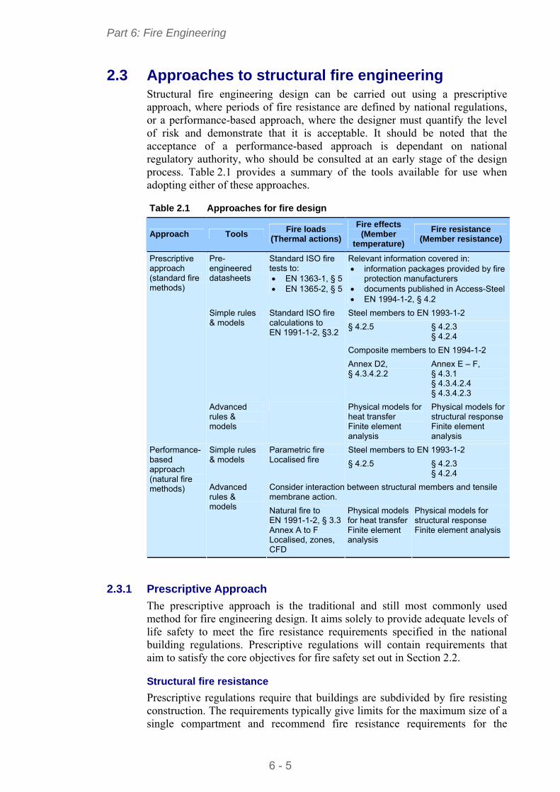
Part 6: Fire Engineering
6 - 5
2.3 Approaches to structural fire engineering Structural fire engineering design can be carried out using a prescriptive approach, where periods of fire resistance are defined by national regulations, or a performance-based approach, where the designer must quantify the level of risk and demonstrate that it is acceptable. It should be noted that the acceptance of a performance-based approach is dependant on national regulatory authority, who should be consulted at an early stage of the design process. Table 2.1 provides a summary of the tools available for use when adopting either of these approaches.
Table 2.1 Approaches for fire design
Approach Tools Fire loads
(Thermal actions)
Fire effects (Member
temperature)
Fire resistance (Member resistance)
Pre-engineered datasheets
Standard ISO fire tests to: EN 1363-1, § 5 EN 1365-2, § 5
Relevant information covered in: information packages provided by fire
protection manufacturers documents published in Access-Steel EN 1994-1-2, § 4.2
Steel members to EN 1993-1-2
§ 4.2.5 § 4.2.3 § 4.2.4
Composite members to EN 1994-1-2
Simple rules & models
Standard ISO fire calculations to EN 1991-1-2, §3.2
Annex D2, § 4.3.4.2.2
Annex E – F, § 4.3.1 § 4.3.4.2.4 § 4.3.4.2.3
Prescriptive approach (standard fire methods)
Advanced rules & models
Physical models for heat transfer Finite element analysis
Physical models for structural response Finite element analysis
Steel members to EN 1993-1-2 Simple rules & models
Parametric fire Localised fire § 4.2.5 § 4.2.3
§ 4.2.4
Consider interaction between structural members and tensile membrane action.
Performance-based approach (natural fire methods) Advanced
rules & models Natural fire to
EN 1991-1-2, § 3.3Annex A to F Localised, zones, CFD
Physical models for heat transfer Finite element analysis
Physical models for structural response Finite element analysis
2.3.1 Prescriptive Approach
The prescriptive approach is the traditional and still most commonly used method for fire engineering design. It aims solely to provide adequate levels of life safety to meet the fire resistance requirements specified in the national building regulations. Prescriptive regulations will contain requirements that aim to satisfy the core objectives for fire safety set out in Section 2.2.
Structural fire resistance
Prescriptive regulations require that buildings are subdivided by fire resisting construction. The requirements typically give limits for the maximum size of a single compartment and recommend fire resistance requirements for the
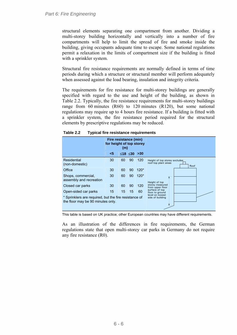
Part 6: Fire Engineering
6 - 6
structural elements separating one compartment from another. Dividing a multi-storey building horizontally and vertically into a number of fire compartments will help to limit the spread of fire and smoke inside the building, giving occupants adequate time to escape. Some national regulations permit a relaxation in the limits of compartment size if the building is fitted with a sprinkler system.
Structural fire resistance requirements are normally defined in terms of time periods during which a structure or structural member will perform adequately when assessed against the load bearing, insulation and integrity criteria.
The requirements for fire resistance for multi-storey buildings are generally specified with regard to the use and height of the building, as shown in Table 2.2. Typically, the fire resistance requirements for multi-storey buildings range from 60 minutes (R60) to 120 minutes (R120), but some national regulations may require up to 4 hours fire resistance. If a building is fitted with a sprinkler system, the fire resistance period required for the structural elements by prescriptive regulations may be reduced.
Table 2.2 Typical fire resistance requirements
Fire resistance (min) for height of top storey
(m)
<5 18 30 >30
Residential (non-domestic)
30 60 90 120
Office 30 60 90 120*
Shops, commercial, assembly and recreation
30 60 90 120*
Closed car parks 30 60 90 120
Open-sided car parks 15 15 15 60
* Sprinklers are required, but the fire resistance of the floor may be 90 minutes only.
Roof
Height of topstorey measured from upper floorsurface of topfloor to groundlevel on lowestside of building
Height of top storey excludesroof-top plant areas
This table is based on UK practice; other European countries may have different requirements.
As an illustration of the differences in fire requirements, the German regulations state that open multi-storey car parks in Germany do not require any fire resistance (R0).
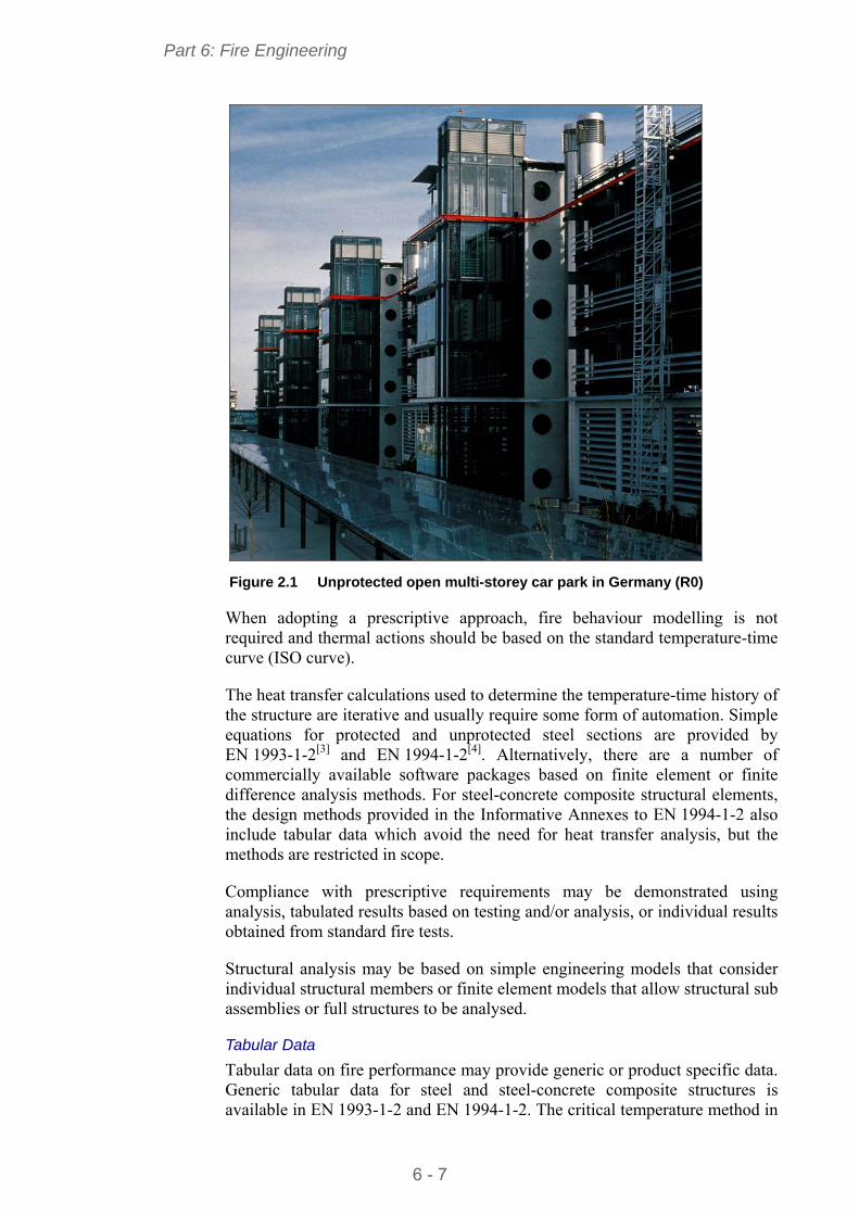
Part 6: Fire Engineering
6 - 7
Figure 2.1 Unprotected open multi-storey car park in Germany (R0)
When adopting a prescriptive approach, fire behaviour modelling is not required and thermal actions should be based on the standard temperature-time curve (ISO curve).
The heat transfer calculations used to determine the temperature-time history of the structure are iterative and usually require some form of automation. Simple equations for protected and unprotected steel sections are provided by EN 1993-1-2[ 3] and EN 1994-1-2[ 4]. Alternatively, there are a number of commercially available software packages based on finite element or finite difference analysis methods. For steel-concrete composite structural elements, the design methods provided in the Informative Annexes to EN 1994-1-2 also include tabular data which avoid the need for heat transfer analysis, but the methods are restricted in scope.
Compliance with prescriptive requirements may be demonstrated using analysis, tabulated results based on testing and/or analysis, or individual results obtained from standard fire tests.
Structural analysis may be based on simple engineering models that consider individual structural members or finite element models that allow structural sub assemblies or full structures to be analysed.
Tabular Data
Tabular data on fire performance may provide generic or product specific data. Generic tabular data for steel and steel-concrete composite structures is available in EN 1993-1-2 and EN 1994-1-2. The critical temperature method in
Part 6: Fire Engineering
6 - 8
EN 1993-1-2 provides a table of critical temperature data expressed in terms of the degree of utilisation. Data for the design of a range of steel concrete composite beams and columns is also provided in tabular format in EN 1994-1-2.
Product-specific tabular data is commonly available for fire protection materials that can be applied to structural steelwork. The required thickness of fire protection is usually expressed as a function of fire resistance period, section factor and critical temperature. Many other building products, such as steel decking for composite floors, also come with product specific design tables.
Simple calculation models
As an alternative to tabular data, the designer may choose to carry out simple calculations to determine the resistance of a member after a given period of fire exposure. The fire action is taken as the standard temperature-time curve in the Eurocodes. The resistance of the member depends on the level of applied load and loss of material strength under fire conditions, and is calculated according to the Eurocode rules.
Simple calculation models are most practical when used to justify the design of unprotected steelwork, usually in circumstances where the fire resistance requirement is R30 or lower. Where protected steelwork is required normal tabular data provided by fire protection manufacturers is more efficient.
The disadvantage of these calculation models is that their application is limited to individual structural members and does not allow for the interaction between the structural member and the surrounding structure.
Advanced calculation models
Advanced calculation models use both engineering fundamentals and finite element techniques to carry out structural fire design. Thermal and structural responses to fire actions may be determined using advanced physical models.
This type of analysis normally leads to a more economic solution than both the prescriptive approach and the simple calculation models. This method helps designers to develop more innovative solutions for building structures and it often proves that it is safe to leave some steel members unprotected without compromising the fire resistance of the structure.
Advanced calculation models demand a considerable amount of calculations to be carried out and require significant expertise from the designer in terms of structural fire engineering and finite element techniques.
Classification of lining materials
National regulations impose controls on the materials used as lining for the walls and ceilings of buildings. These materials must resist the spread of flames across the surfaces and must not contribute significantly to the fire in terms of heat release or smoke production. Lining materials are categorised on the basis of the result of reaction to fire tests.
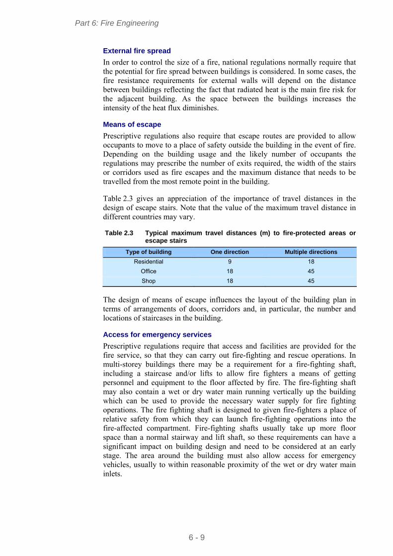
Part 6: Fire Engineering
6 - 9
External fire spread
In order to control the size of a fire, national regulations normally require that the potential for fire spread between buildings is considered. In some cases, the fire resistance requirements for external walls will depend on the distance between buildings reflecting the fact that radiated heat is the main fire risk for the adjacent building. As the space between the buildings increases the intensity of the heat flux diminishes.
Means of escape
Prescriptive regulations also require that escape routes are provided to allow occupants to move to a place of safety outside the building in the event of fire. Depending on the building usage and the likely number of occupants the regulations may prescribe the number of exits required, the width of the stairs or corridors used as fire escapes and the maximum distance that needs to be travelled from the most remote point in the building.
Table 2.3 gives an appreciation of the importance of travel distances in the design of escape stairs. Note that the value of the maximum travel distance in different countries may vary.
Table 2.3 Typical maximum travel distances (m) to fire-protected areas or escape stairs
Type of building One direction Multiple directions
Residential 9 18
Office 18 45
Shop 18 45
The design of means of escape influences the layout of the building plan in terms of arrangements of doors, corridors and, in particular, the number and locations of staircases in the building.
Access for emergency services
Prescriptive regulations require that access and facilities are provided for the fire service, so that they can carry out fire-fighting and rescue operations. In multi-storey buildings there may be a requirement for a fire-fighting shaft, including a staircase and/or lifts to allow fire fighters a means of getting personnel and equipment to the floor affected by fire. The fire-fighting shaft may also contain a wet or dry water main running vertically up the building which can be used to provide the necessary water supply for fire fighting operations. The fire fighting shaft is designed to given fire-fighters a place of relative safety from which they can launch fire-fighting operations into the fire-affected compartment. Fire-fighting shafts usually take up more floor space than a normal stairway and lift shaft, so these requirements can have a significant impact on building design and need to be considered at an early stage. The area around the building must also allow access for emergency vehicles, usually to within reasonable proximity of the wet or dry water main inlets.
Part 6: Fire Engineering
6 - 10
2.3.2 Performance-based approach
A performance-based fire design procedure should be clearly documented so that the philosophy and assumptions can be clearly understood by a third party. The procedure may include the following main steps:
Review the architectural design of the building
Establish fire safety objectives
Identify fire hazards and possible consequences
Establish possible fire safety strategies
Identify acceptance criteria and methods of analysis
Establish fire scenarios for analysis.
Review of architectural design
This review should aim to identify any architectural or client requirements that may be significant in the development of a fire safety solution, for example:
The future use of the building and the anticipated building contents, as well as the anticipated permanent, variable and thermal actions
The type of structure and building layout
The presence of smoke ventilation systems or sprinkler systems
The characteristics of the buildings occupants, the number of people likely to be in the building and their distribution
The type of fire detection and alarm system
The degree of building management throughout the life of the building (for example, maintaining active fire safety measures or ensuring that combustible materials are not allowed to accumulate in vulnerable areas).
Fire safety objectives
At an early stage of the design process, the fire safety objectives should be clearly identified. This process will be undertaken ideally in consultation with the client, regulatory authority and other stakeholders.
The main fire safety objectives that may be addressed are life safety, control of financial loss and environmental protection.
Life safety objectives are already set out in prescriptive regulations, but should include provisions to ensure that the building occupants can evacuate the building in reasonable safety, that fire-fighters can operate in reasonable safety and that collapse does not endanger people who are likely to be near the building.
The effects of fire on the continuing viability of a business can be substantial and consideration should be given to minimising damage to the structure and fabric of the building, the building contents, the on-going business viability and the corporate image. The level of precautions that are deemed necessary in a particular building will depend on the size and nature of the business undertaken in it. In some cases, it may be easy to relocate the business to
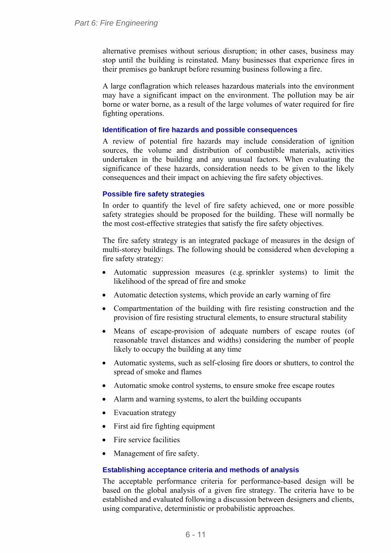
Part 6: Fire Engineering
6 - 11
alternative premises without serious disruption; in other cases, business may stop until the building is reinstated. Many businesses that experience fires in their premises go bankrupt before resuming business following a fire.
A large conflagration which releases hazardous materials into the environment may have a significant impact on the environment. The pollution may be air borne or water borne, as a result of the large volumes of water required for fire fighting operations.
Identification of fire hazards and possible consequences
A review of potential fire hazards may include consideration of ignition sources, the volume and distribution of combustible materials, activities undertaken in the building and any unusual factors. When evaluating the significance of these hazards, consideration needs to be given to the likely consequences and their impact on achieving the fire safety objectives.
Possible fire safety strategies
In order to quantify the level of fire safety achieved, one or more possible safety strategies should be proposed for the building. These will normally be the most cost-effective strategies that satisfy the fire safety objectives.
The fire safety strategy is an integrated package of measures in the design of multi-storey buildings. The following should be considered when developing a fire safety strategy:
Automatic suppression measures (e.g. sprinkler systems) to limit the likelihood of the spread of fire and smoke
Automatic detection systems, which provide an early warning of fire
Compartmentation of the building with fire resisting construction and the provision of fire resisting structural elements, to ensure structural stability
Means of escape-provision of adequate numbers of escape routes (of reasonable travel distances and widths) considering the number of people likely to occupy the building at any time
Automatic systems, such as self-closing fire doors or shutters, to control the spread of smoke and flames
Automatic smoke control systems, to ensure smoke free escape routes
Alarm and warning systems, to alert the building occupants
Evacuation strategy
First aid fire fighting equipment
Fire service facilities
Management of fire safety.
Establishing acceptance criteria and methods of analysis
The acceptable performance criteria for performance-based design will be based on the global analysis of a given fire strategy. The criteria have to be established and evaluated following a discussion between designers and clients, using comparative, deterministic or probabilistic approaches.
Part 6: Fire Engineering
6 - 12
A comparative approach evaluates the level of fire safety obtained from performance-based design in relation to that from a prescriptive approach, to ensure an equivalent level of fire safety is achieved. A deterministic approach aims to quantify the effects of a worst case fire scenario and to demonstrate that the effects will not exceed the acceptance criteria defined. A probabilistic approach aims to show that the fire safety strategy makes the likelihood of large losses occurring sufficiently small.
Establishing fire scenarios
The number of possible fire scenarios in any building can become large and resources to analyse all of them are usually not available. Therefore detailed analysis must be confined to the most significant fire scenarios or the worst creditable case as it is sometimes referred to. The failure of protection systems should also be included in the fire scenarios considered. In most buildings more than one fire scenario will require detailed analysis.
2.3.3 Choice of optimum approach
The choice of an optimum approach for the fire design of multi-storey buildings depends on various parameters, such as geometry, structural features, service function and designers’ knowledge of fire design. Table 2.4 provides some suggestions as to which approach may result in a more economic solution.
Overall, for low-rise buildings with a small floor area, the pre-engineered datasheet approach may be the optimum choice. For high-rise buildings with a large floor area or to take into account the benefits of active protection measures, economic benefits may be obtained using advanced calculation models. For most medium size buildings, simple calculation models may result in the most economic solution.
Table 2.4 Choice of optimum approach for fire engineering design
Features of building Datasheets Simple
calculation models
Advanced calculation
models
1 Building size - floor area per storey, A
Small: A < 200 m2
Medium: 200 m2 < A < 2000 m2
Large: A > 2000 m2
2 Building height – number of storeys, n
Low: n ≤ 5
High: n > 6
Most economic solution
Probably an economic solution
The use of active fire protection measures, such as detectors, alarms or sprinklers, is beneficial if advanced calculation methods are used. It is noted
Part 6: Fire Engineering
6 - 13
that some national regulations and/or local authorities allow a reduction in the fire loads when these measures are present.
The ease of access to specialists in fire design will facilitate the use of advanced methods. However, for those designers with no experience in the field, the use of simple methods or the datasheets is likely to make the project more economic, as important savings can be made in the design costs.
In this regard, Table 2.5 outlines the recommended approach to be used depending on the skills of the designer and indicates which Section of this guide covers the relevant information.
Table 2.5 Impact of the skills of the designer in the fire solution
Knowledge in fire engineering design
Recommended design approach (section of this guide which covers the method)
Non-specialist Active fire protection ( 3.1) Passive fire protection ( 3.2) Alternative fire resisting systems ( 3.3)
Limited knowledge Simple calculation methods ( 4) Tensile membrane action ( 5)
Specialist Advanced calculation methods ( 6)
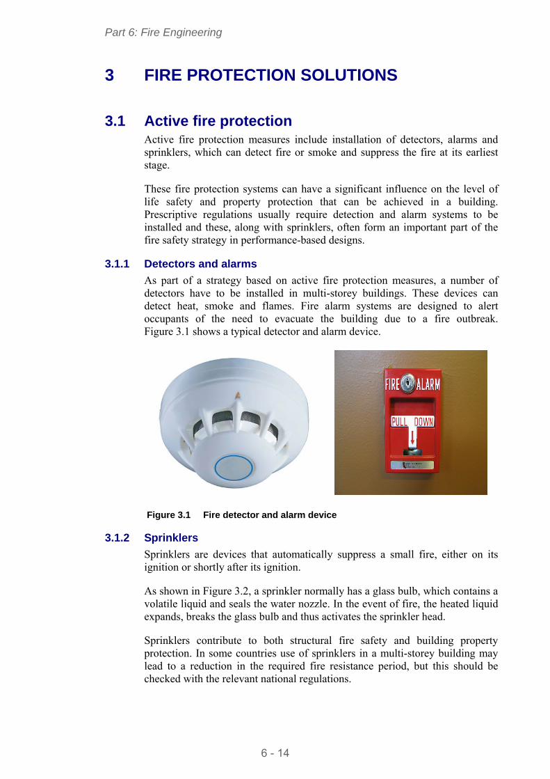
Part 6: Fire Engineering
6 - 14
3 FIRE PROTECTION SOLUTIONS
3.1 Active fire protection Active fire protection measures include installation of detectors, alarms and sprinklers, which can detect fire or smoke and suppress the fire at its earliest stage.
These fire protection systems can have a significant influence on the level of life safety and property protection that can be achieved in a building. Prescriptive regulations usually require detection and alarm systems to be installed and these, along with sprinklers, often form an important part of the fire safety strategy in performance-based designs.
3.1.1 Detectors and alarms
As part of a strategy based on active fire protection measures, a number of detectors have to be installed in multi-storey buildings. These devices can detect heat, smoke and flames. Fire alarm systems are designed to alert occupants of the need to evacuate the building due to a fire outbreak. Figure 3.1 shows a typical detector and alarm device.
Figure 3.1 Fire detector and alarm device
3.1.2 Sprinklers
Sprinklers are devices that automatically suppress a small fire, either on its ignition or shortly after its ignition.
As shown in Figure 3.2, a sprinkler normally has a glass bulb, which contains a volatile liquid and seals the water nozzle. In the event of fire, the heated liquid expands, breaks the glass bulb and thus activates the sprinkler head.
Sprinklers contribute to both structural fire safety and building property protection. In some countries use of sprinklers in a multi-storey building may lead to a reduction in the required fire resistance period, but this should be checked with the relevant national regulations.
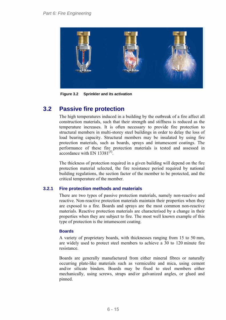
Part 6: Fire Engineering
6 - 15
Figure 3.2 Sprinkler and its activation
3.2 Passive fire protection The high temperatures induced in a building by the outbreak of a fire affect all construction materials, such that their strength and stiffness is reduced as the temperature increases. It is often necessary to provide fire protection to structural members in multi-storey steel buildings in order to delay the loss of load bearing capacity. Structural members may be insulated by using fire protection materials, such as boards, sprays and intumescent coatings. The performance of these fire protection materials is tested and assessed in accordance with EN 13381[ 5].
The thickness of protection required in a given building will depend on the fire protection material selected, the fire resistance period required by national building regulations, the section factor of the member to be protected, and the critical temperature of the member.
3.2.1 Fire protection methods and materials
There are two types of passive protection materials, namely non-reactive and reactive. Non-reactive protection materials maintain their properties when they are exposed to a fire. Boards and sprays are the most common non-reactive materials. Reactive protection materials are characterised by a change in their properties when they are subject to fire. The most well known example of this type of protection is the intumescent coating.
Boards
A variety of proprietary boards, with thicknesses ranging from 15 to 50 mm, are widely used to protect steel members to achieve a 30 to 120 minute fire resistance.
Boards are generally manufactured from either mineral fibres or naturally occurring plate-like materials such as vermiculite and mica, using cement and/or silicate binders. Boards may be fixed to steel members either mechanically, using screws, straps and/or galvanized angles, or glued and pinned.
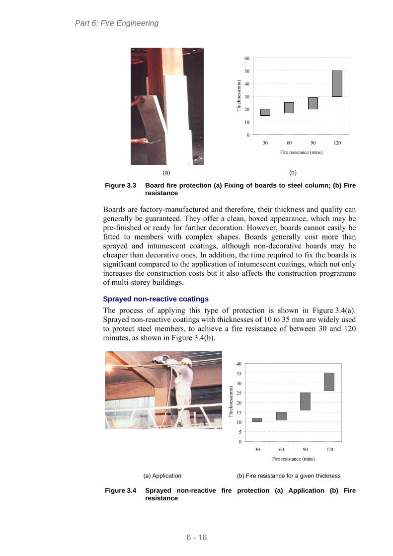
Part 6: Fire Engineering
6 - 16
0
10
20
30
40
50
60
30 60 90 120
Fire resistance (mins)
Thi
ckne
ss(m
m)
(a) (b) Figure 3.3 Board fire protection (a) Fixing of boards to steel column; (b) Fire
resistance
Boards are factory-manufactured and therefore, their thickness and quality can generally be guaranteed. They offer a clean, boxed appearance, which may be pre-finished or ready for further decoration. However, boards cannot easily be fitted to members with complex shapes. Boards generally cost more than sprayed and intumescent coatings, although non-decorative boards may be cheaper than decorative ones. In addition, the time required to fix the boards is significant compared to the application of intumescent coatings, which not only increases the construction costs but it also affects the construction programme of multi-storey buildings.
Sprayed non-reactive coatings
The process of applying this type of protection is shown in Figure 3.4(a). Sprayed non-reactive coatings with thicknesses of 10 to 35 mm are widely used to protect steel members, to achieve a fire resistance of between 30 and 120 minutes, as shown in Figure 3.4(b).
0
5
10
15
20
25
30
35
40
30 60 90 120
Fire resistance (mins)
Thi
ckne
ss(m
m)
(a) Application (b) Fire resistance for a given thickness Figure 3.4 Sprayed non-reactive fire protection (a) Application (b) Fire
resistance
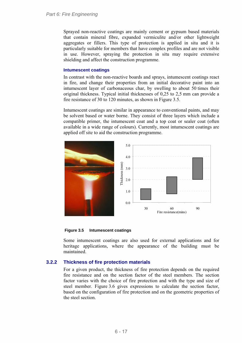
Part 6: Fire Engineering
6 - 17
Sprayed non-reactive coatings are mainly cement or gypsum based materials that contain mineral fibre, expanded vermiculite and/or other lightweight aggregates or fillers. This type of protection is applied in situ and it is particularly suitable for members that have complex profiles and are not visible in use. However, spraying the protection in situ may require extensive shielding and affect the construction programme.
Intumescent coatings
In contrast with the non-reactive boards and sprays, intumescent coatings react in fire, and change their properties from an initial decorative paint into an intumescent layer of carbonaceous char, by swelling to about 50 times their original thickness. Typical initial thicknesses of 0,25 to 2,5 mm can provide a fire resistance of 30 to 120 minutes, as shown in Figure 3.5.
Intumescent coatings are similar in appearance to conventional paints, and may be solvent based or water borne. They consist of three layers which include a compatible primer, the intumescent coat and a top coat or sealer coat (often available in a wide range of colours). Currently, most intumescent coatings are applied off site to aid the construction programme.
0.0
1.0
2.0
3.0
4.0
5.0
30 60 90Fire resistance(mins)
Thi
ckne
ss (
mm
)
Figure 3.5 Intumescent coatings
Some intumescent coatings are also used for external applications and for heritage applications, where the appearance of the building must be maintained.
3.2.2 Thickness of fire protection materials
For a given product, the thickness of fire protection depends on the required fire resistance and on the section factor of the steel members. The section factor varies with the choice of fire protection and with the type and size of steel member. Figure 3.6 gives expressions to calculate the section factor, based on the configuration of fire protection and on the geometric properties of the steel section.
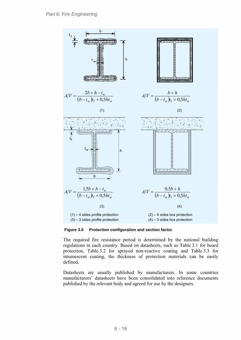
Part 6: Fire Engineering
6 - 18
wfw
w
5,0
2
htttb
thbVA
(1)
wfw 5,0 htttb
hbVA
(2)
b
t
t
w
f
h
wfw
w
5,0
5,1
htttb
thbVA
(3)
wfw 5,0
5,0
htttb
hbVA
(4)
(1) – 4 sides profile protection (2) – 4 sides box protection (3) – 3 sides profile protection (4) – 3 sides box protection
Figure 3.6 Protection configuration and section factor
The required fire resistance period is determined by the national building regulations in each country. Based on datasheets, such as Table 3.1 for board protection, Table 3.2 for sprayed non-reactive coating and Table 3.3 for intumescent coating, the thickness of protection materials can be easily defined.
Datasheets are usually published by manufacturers. In some countries manufacturers’ datasheets have been consolidated into reference documents published by the relevant body and agreed for use by the designers.
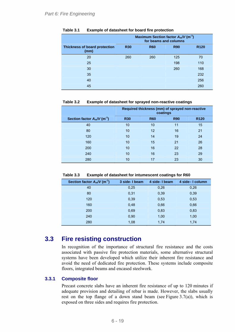
Part 6: Fire Engineering
6 - 19
Table 3.1 Example of datasheet for board fire protection
Maximum Section factor Am/V (m-1) for beams and columns
Thickness of board protection (mm)
R30 R60 R90 R120
20 260 260 125 70
25 198 110
30 260 168
35 232
40 256
45 260
Table 3.2 Example of datasheet for sprayed non-reactive coatings
Required thickness (mm) of sprayed non-reactive coatings
Section factor Am/V (m-1) R30 R60 R90 R120
40 10 10 11 15
80 10 12 16 21
120 10 14 19 24
160 10 15 21 26
200 10 16 22 28
240 10 16 23 29
280 10 17 23 30
Table 3.3 Example of datasheet for intumescent coatings for R60
Section factor Am/V (m-1) 3 side- I beam 4 side- I beam 4 side– I column
40 0,25 0,26 0,26
80 0,31 0,39 0,39
120 0,39 0,53 0,53
160 0,48 0,66 0,66
200 0,69 0,83 0,83
240 0,90 1,00 1,00
280 1,08 1,74 1,74
3.3 Fire resisting construction In recognition of the importance of structural fire resistance and the costs associated with passive fire protection materials, some alternative structural systems have been developed which utilize their inherent fire resistance and avoid the need of dedicated fire protection. These systems include composite floors, integrated beams and encased steelwork.
3.3.1 Composite floor
Precast concrete slabs have an inherent fire resistance of up to 120 minutes if adequate provision and detailing of rebar is made. However, the slabs usually rest on the top flange of a down stand beam (see Figure 3.7(a)), which is exposed on three sides and requires fire protection.
Part 6: Fire Engineering
6 - 20
As an alternative to precast concrete floors, composite floors, shown in Figure 3.7(b), are popular in multi-storey buildings.
(a) (b) Figure 3.7 (a) Precast concrete floor on down stand beam; (b) composite
floors with steel decking
Composite floors are constructed using either trapezoidal or re-entrant profiled steel decking that supports the concrete on top. In a composite floor, the concrete is reinforced using fibre or bar reinforcement to control cracks caused by the flexural tension at the floor support, and by shrinkage and settlement of the concrete. In addition to controlling cracks, the bar reinforcement also provides the floor with bending resistance at its support in the fire condition.
For a composite floor with the bottom surface exposed, the insulation criterion is usually satisfied by providing sufficient insulation depth of the concrete for the required fire resistance period, as shown in Table 3.4. The longer the required fire resistance period, the thicker the insulation concrete needs to be. The integrity criterion is generally met by using continuous steel decking.
Table 3.4 Typical minimum insulation thickness (mm), h1, of concrete in composite floors
Trapezoidal steel decking Re-entrant steel decking
Required Fire Resistance (minutes)
Normal weight concrete
Light weight concrete
Normal weight concrete
Light weight concrete
60 70 60 90 90
90 80 70 110 105
120 90 80 125 115
Table 3.5 shows typical depths and spans of composite floors with normal weight concrete under a uniform applied load of 5,0 kN/mm2.
h1
h2 h2
h1
Part 6: Fire Engineering
6 - 21
Table 3.5 Typical depths and spans of composite floors
Trapezoidal steel decking Re-entrant steel decking
Single span Double span Single span Double span
Required fire Resistance (minutes)
Depth (mm)
Span (m)
Depth (mm)
Span (m)
Depth (mm)
Span (m)
Depth (mm)
Span (m)
60 140 3,8 140 4,2 101 3,0 101 3,4
90 150 3,1 150 3,3 105 2,9 105 3,3
120 160 3,1 160 3,4 115 2,4 115 2,9
3.3.2 Integrated beams
Integrated beams are part of a floor construction system where the steel beams are contained within the depth of an in-situ or pre-cast concrete slab, instead of supporting the slab on the top flanges of the beams. Consequently, the overall depth of the floor construction is minimized. The whole steel section, except for its bottom flange or plate, is insulated from the fire by the surrounding concrete.
Figure 3.8 ASB - Integrated beam (rolled asymmetric steel beam)
Figure 3.9 IFB - Integrated beam (I-section with a plate welded to its bottom
flange)
d d
Part 6: Fire Engineering
6 - 22
There are two types of open section integrated beams: asymmetric steel beam (ASB) and integrated fabricated beam (IFB), as shown in Figure 3.8 and Figure 3.9 respectively.
Generally, integrated beams can achieve up to 60 minutes fire resistance without being fire-protected. With the inclusion of additional longitudinal reinforcement, 90 minutes fire resistance is possible with an unprotected bottom flange. The total structural depths and typical spans of integrated beams are summarised in Table 3.6, which may be referred to at the preliminary design of multi-storey buildings.
Table 3.6 Structural depth and typical span of integrated beams
Type of floor Depth (mm) Span (m)
ASB Integrated beam 280 to 400 6 to 9
IFB Integrated beam 250 to 450 6 to 9
3.3.3 Partially encased beams and columns
Partially encased beams and columns are constructed by filling the space between the flanges of I-sections using plain or reinforced concrete, as shown in Figure 3.10 and Figure 3.11.
Compared with the unprotected I-sections, which only have about 15 minutes fire resistance, partially encased sections can achieve over 60 minutes, which normally meets the fire resistance requirements of many multi-storey buildings. The increase in fire resistance period is due to the coverage of most parts of the surface area of the steelwork using concrete, which has a low thermal conductivity. Longer periods of fire resistance can also be achieved by increasing the amount of reinforcement embedded within the concrete, to compensate the loss of the strength of the steelwork in fire.
u
u
1e
e
f
h
h
c
c
beff
2w
b
A
As
ff exb=A
Figure 3.10 Partially encased beam
EN 1994-1-2 offers relatively simple rules and established datasheets in clauses §4.2.2 and §4.2.3 for fire design of composite beams and columns, including partially encased steel sections. These rules relate the fire resistance of
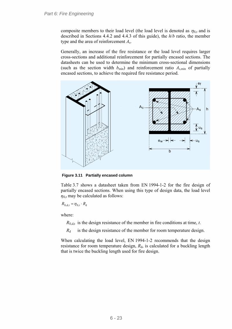
Part 6: Fire Engineering
6 - 23
composite members to their load level (the load level is denoted as fi,t and is described in Sections 4.4.2 and 4.4.3 of this guide), the h/b ratio, the member type and the area of reinforcement As.
Generally, an increase of the fire resistance or the load level requires larger cross-sections and additional reinforcement for partially encased sections. The datasheets can be used to determine the minimum cross-sectional dimensions (such as the section width bmin) and reinforcement ratio As,min of partially encased sections, to achieve the required fire resistance period.
cAA
u
u
s
s
e
e
w
b
s
f
h
Figure 3.11 Partially encased column
Table 3.7 shows a datasheet taken from EN 1994-1-2 for the fire design of partially encased sections. When using this type of design data, the load level ηfi,t may be calculated as follows:
dtfi,td,fi, RR
where:
Rfi,d,t is the design resistance of the member in fire conditions at time, t.
Rd is the design resistance of the member for room temperature design.
When calculating the load level, EN 1994-1-2 recommends that the design resistance for room temperature design, Rd, is calculated for a buckling length that is twice the buckling length used for fire design.
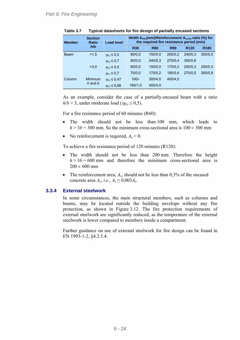
Part 6: Fire Engineering
6 - 24
Table 3.7 Typical datasheets for fire design of partially encased sections
Width bmin(mm)/Reinforcement As,min ratio (%) for the required fire resistance period (min) Member
Section Ratio h/b
Load level
R30 R60 R90 R120 R180
fi,t ≤ 0,5 80/0,0 150/0,0 200/0,2 240/0,3 300/0,5 >1,5
fi,t ≤ 0,7 80/0,0 240/0,3 270/0,4 300/0,6
fi,t ≤ 0,5 60/0,0 100/0,0 170/0,2 200/0,3 250/0,3
Beam
>3,0
fi,t ≤ 0,7 70/0,0 170/0,2 190/0,4 270/0,5 300/0,8
fi,t ≤ 0,47 160/- 300/4,0 400/4,0 Column Minimum h and b fi,t ≤ 0,66 160/1,0 400/4,0
As an example, consider the case of a partially-encased beam with a ratio h/b > 3, under moderate load (fi,t ≤ 0,5).
For a fire resistance period of 60 minutes (R60):
The width should not be less than 100 mm, which leads to h > 3b = 300 mm. So the minimum cross-sectional area is 100 300 mm
No reinforcement is required, As = 0.
To achieve a fire resistance period of 120 minutes (R120):
The width should not be less than 200 mm. Therefore the height h > 3b = 600 mm and therefore the minimum cross-sectional area is 200 600 mm
The reinforcement area, As, should not be less than 0,3% of the encased concrete area Ac, i.e., As ≥ 0,003Ac.
3.3.4 External steelwork
In some circumstances, the main structural members, such as columns and beams, may be located outside the building envelope without any fire protection, as shown in Figure 3.12. The fire protection requirements of external steelwork are significantly reduced, as the temperature of the external steelwork is lower compared to members inside a compartment.
Further guidance on use of external steelwork for fire design can be found in EN 1993-1-2, §4.2.5.4.
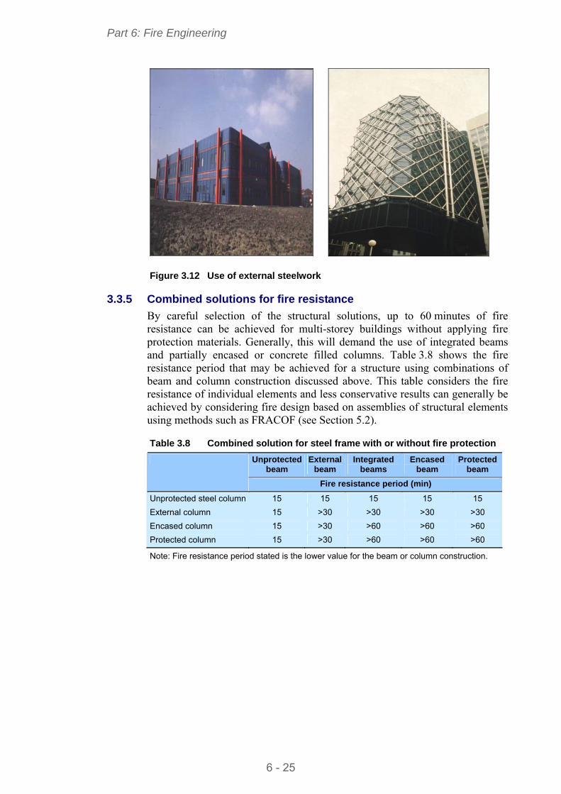
Part 6: Fire Engineering
6 - 25
Figure 3.12 Use of external steelwork
3.3.5 Combined solutions for fire resistance
By careful selection of the structural solutions, up to 60 minutes of fire resistance can be achieved for multi-storey buildings without applying fire protection materials. Generally, this will demand the use of integrated beams and partially encased or concrete filled columns. Table 3.8 shows the fire resistance period that may be achieved for a structure using combinations of beam and column construction discussed above. This table considers the fire resistance of individual elements and less conservative results can generally be achieved by considering fire design based on assemblies of structural elements using methods such as FRACOF (see Section 5.2).
Table 3.8 Combined solution for steel frame with or without fire protection
Unprotected beam
External beam
Integrated beams
Encased beam
Protected beam
Fire resistance period (min)
Unprotected steel column 15 15 15 15 15
External column 15 >30 >30 >30 >30
Encased column 15 >30 >60 >60 >60
Protected column 15 >30 >60 >60 >60
Note: Fire resistance period stated is the lower value for the beam or column construction.
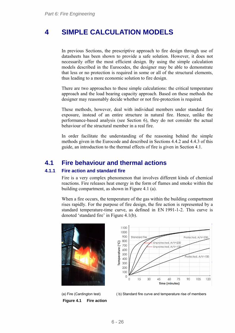
Part 6: Fire Engineering
6 - 26
4 SIMPLE CALCULATION MODELS
In previous Sections, the prescriptive approach to fire design through use of datasheets has been shown to provide a safe solution. However, it does not necessarily offer the most efficient design. By using the simple calculation models described in the Eurocodes, the designer may be able to demonstrate that less or no protection is required in some or all of the structural elements, thus leading to a more economic solution to fire design.
There are two approaches to these simple calculations: the critical temperature approach and the load bearing capacity approach. Based on these methods the designer may reasonably decide whether or not fire-protection is required.
These methods, however, deal with individual members under standard fire exposure, instead of an entire structure in natural fire. Hence, unlike the performance-based analysis (see Section 6), they do not consider the actual behaviour of the structural member in a real fire.
In order facilitate the understanding of the reasoning behind the simple methods given in the Eurocode and described in Sections 4.4.2 and 4.4.3 of this guide, an introduction to the thermal effects of fire is given in Section 4.1.
4.1 Fire behaviour and thermal actions 4.1.1 Fire action and standard fire
Fire is a very complex phenomenon that involves different kinds of chemical reactions. Fire releases heat energy in the form of flames and smoke within the building compartment, as shown in Figure 4.1 (a).
When a fire occurs, the temperature of the gas within the building compartment rises rapidly. For the purpose of fire design, the fire action is represented by a standard temperature-time curve, as defined in EN 1991-1-2. This curve is denoted ‘standard fire’ in Figure 4.1(b).
(a) Fire (Cardington test) ( b) Standard fire curve and temperature rise of members
Figure 4.1 Fire action
Part 6: Fire Engineering
6 - 27
The temperature rise of a member in fire is predominantly governed by radiation and convection mechanisms, via a complex diffusion process. It depends on the thermal properties of the materials and the thickness of the protection layer, if it is fire-protected.
Due to the rapid increase of the gas temperature, the heat energy from the fire (i.e. thermal action) flows into the member through the exposed surfaces, and heats up the member. As a result, the temperature of the member rises, typically following the curves shown in Figure 4.1 (b) for different scenarios of protected and unprotected members.
4.1.2 Modelling fire behaviour
As a thermal action on building structures, a fire can be classified into localised and fully-developed fires.
Localised fire
A localised fire is in the pre-flashover phase and occurs only in some part of a compartment. A localised fire is unlikely to spread to the whole compartment and to cause a flashover, due to its slow propagation and the low temperature developed. A localised fire is generally modelled using plume, zones and computational fluid dynamics (CFD) models.
Plume model
Annex C of EN 1991-1-2 gives a so-called plume model to determine the thermal action of a localised fire. If the flame remains below the ceiling, as shown in Figure 4.2 (a), the model is used to calculate the corresponding temperature along its vertical axis. However, if the flame impacts the ceiling, as shown in Figure 4.2 (b) then the model determines the heat flux at the level of the ceiling together with the flame length.
a) Flame remains below the ceiling (b) Flame impacts the ceiling Figure 4.2 Plume model for a localised fire in EN 1991-1-2
4.1.3 Fully developed fire
A fire is fully developed when all the available fuels within a compartment are burning simultaneously and the maximum heat is released. A fully developed fire is commonly modelled using either standard or parametric fires, as shown
Part 6: Fire Engineering
6 - 28
in Figure 4.3. The severity of a fully developed fire is governed by the ventilation condition and quantity and nature of the fuel within the compartment.
Standard Fire
Parametric fire
0
200
400
600
800
1000
1200
0 30 60 90 120 150 180
Time (min)
Gas Temperature (°C)
Figure 4.3 Model of fully developed fire
4.1.4 Nominal temperature-time curve
Standard fire
EN 1991-1-2, §3.2 uses the standard temperature-time curve to represent the thermal action of a fully developed fire. This ‘standard fire’ is used to classify the fire performance of the structural materials and members in standard fire furnace tests. It forms the basis on which the fire resistance time and load bearing resistance of structural members are evaluated using the simple calculation models from EN 1993-1-2 and EN 1994-1-2. It is also used in the performance-based analysis for fire design of a whole structure.
4.1.5 Natural fire model
Parametric fire
EN 1991-1-2, Annex A defines a parametric temperature-time curve for fire compartments up to 500 m2 floor area. This ‘parametric fire’ consists of a heating, cooling and residual phases. The heating phase is normally represented using an exponential curve up to a maximum temperature. The cooling phase is described by a sloping straight line until it reaches the residual phase. For a parametric fire, the heating phase depends on ventilation conditions and the thermal properties of the compartment boundary. The heating duration and maximum temperature are governed by the density of the fire loads and the ventilation condition. The cooling phase is controlled by the heating duration and the maximum temperature that has been reached.
To some extent, the parametric fire represents the characteristics of a natural fire. However, its accuracy for estimating the thermal response of fire depends on the accuracy of the input data, such as fire load, ventilation condition, compartment size and thermal properties of the boundary condition.
Part 6: Fire Engineering
6 - 29
4.2 Heat transfer This Section explains the fire actions and the evolution of the temperature in structural members under a standard fire exposure, with an emphasis on the concepts of standard fire and section factor.
Section factor Am/V
An important parameter in the rate at which the temperature of a member increases is the ratio Am/V of the member, commonly known as the section factor. The section factor is defined as the ratio of the exposed surface area of a member to its volume per unit length.
The influence of the section factor is shown in Figure 4.1(b) for protected and unprotected members. A larger section factor leads to a faster heating of the member. For example, after 15 minutes of fire exposure, the temperature of an unprotected member with a section factor of Am/V = 200 increases to about 580C, while that of the unprotected member with Am/V = 100 only reaches 380C.
This difference is due to the fact that a large value of the section factor represents a large exposed surface area compared with its volume, and therefore, the member receives more heat than that with a low section factor, which represents a small exposed surface area. This is illustrated in Figure 4.4.
Figure 4.4 Definition of section factor Am/V of a member in fire
Member temperature at time t
The temperature θa,t of the member at time t can be calculated using the simple models given in §4.2.5 of EN 1993-1-2 or §4.3.4.2 of EN 1994-1-2.
If the critical temperature exceeds the design temperature, i.e. θcr > θa,t then the fire resistance of the unprotected member is adequate for that duration.
Part 6: Fire Engineering
6 - 30
If the unprotected member is not adequate, measures have to be taken to improve its fire resistance by:
Choosing a larger cross-section for the steel member
Selecting a higher grade of steel
Providing the necessary fire protection.
4.3 Structural Analysis Figure 4.5 illustrates the general behaviour of a structural member under the effect of the standard fire and applied actions. As the gas temperature θg rises, the member temperature θa,t increases and its load bearing resistance Rfi,d,t decreases.
The critical temperature θcr is defined as the temperature at which a member can no longer support the design effects of the applied actions. The effects of actions (also called action effects) on a member are the internal forces or moments induced by the actions. For example the wind blowing on a structure is an action (the wind action) and the internal forces and bending moments induced in a column are the effects.
Given a structure subject to various actions (e.g. wind, gravity), a member is subject to the design value of an effect, Ed. Under the same actions but also subject to fire, the effects on the member are modified, and denoted as Efi,d.
The critical temperature θcr is therefore defined as the temperature at the time of failure, when the resistance of a member is equal to the effect on it:
Rfi,d,t = Efi,d.
Figure 4.5 Behaviour of a structural member in fire
Member temperature θa,t
Gas temperature θ g Member resistance Rfi,d,t
Load resistance Temperature
tfi,dtrequ Time
Effect of fire action
E fi,d
Critical temperature θ cr
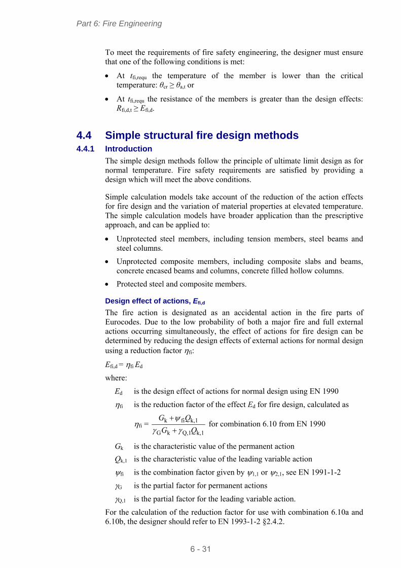
Part 6: Fire Engineering
6 - 31
To meet the requirements of fire safety engineering, the designer must ensure that one of the following conditions is met:
At tfi,requ the temperature of the member is lower than the critical temperature: θcr ≥ θa,t or
At tfi,requ the resistance of the members is greater than the design effects: Rfi,d,t ≥ Efi,d.
4.4 Simple structural fire design methods 4.4.1 Introduction
The simple design methods follow the principle of ultimate limit design as for normal temperature. Fire safety requirements are satisfied by providing a design which will meet the above conditions.
Simple calculation models take account of the reduction of the action effects for fire design and the variation of material properties at elevated temperature. The simple calculation models have broader application than the prescriptive approach, and can be applied to:
Unprotected steel members, including tension members, steel beams and steel columns.
Unprotected composite members, including composite slabs and beams, concrete encased beams and columns, concrete filled hollow columns.
Protected steel and composite members.
Design effect of actions, Efi,d
The fire action is designated as an accidental action in the fire parts of Eurocodes. Due to the low probability of both a major fire and full external actions occurring simultaneously, the effect of actions for fire design can be determined by reducing the design effects of external actions for normal design using a reduction factor fi:
Efi,d = fi Ed
where:
Ed is the design effect of actions for normal design using EN 1990
fi is the reduction factor of the effect Ed for fire design, calculated as
fi = k,1Q,1kG
k,1fik
QG
QG
for combination 6.10 from EN 1990
Gk is the characteristic value of the permanent action
Qk,1 is the characteristic value of the leading variable action
fi is the combination factor given by 1,1 or 2,1, see EN 1991-1-2
G is the partial factor for permanent actions
Q,1 is the partial factor for the leading variable action.
For the calculation of the reduction factor for use with combination 6.10a and 6.10b, the designer should refer to EN 1993-1-2 §2.4.2.
Part 6: Fire Engineering
6 - 32
4.4.2 Critical temperature approach
The basis for this approach is to calculate the temperature of the member after the required period of fire resistance and to compare it to the critical temperature, at which the member would collapse. The steps that must be followed to apply the critical temperature approach are shown in Figure 4.6.
Selection of protected or unprotected
member
Calculate resistance for
Normal design, Rd
(M, N and V)
Rd > Ed ?
Calculate member temperature θa,t at
tfi,requ
θcr > θa,t ?
Appropriate design
Add protection
Calculate critical temperature, θcr
Degree of utilisation, fi
tfi,requ
Am / V
Design effect, Ed
Yes
No
Yes
No
EN 1993
EN 1993-1-2, §4.2.5EN 1994-1-2, §4.3.4.2
EN 1993-1-2, §2.4.2
EN 1993-1-2, §4.2.4
EN 1993-1-2, Tables 4.2 and 4.3
National regulations
Figure 4.6 Fire design of members using the critical temperature approach
Critical temperature
The simple model with the critical temperature approach can only be used for individual members, when their deformation criteria or stability considerations do not have to be taken into account. This approach is only permitted for
Part 6: Fire Engineering
6 - 33
tension members and for restrained beams, but not for unrestrained beams and columns when buckling is a potential failure mode.
The critical temperature of a non-composite steel member can be calculated using the simple model given in §4.2.4 of EN 1993-1-2. The critical temperature decreases with the degree of utilisation of the member, μ0, which is defined as the ratio of the design effect of actions at elevated temperature, Efi,d, to the member resistance at normal temperature but using partial factors for fire design Rfi,d,0 such that:
μ0 = Efi,d/Rfi,d,0
For Class 4 sections, a critical temperature of 350°C is recommended.
The critical temperature of composite members is given by §4.3.4.2.3 of EN 1994-1-2.
4.4.3 Load bearing capacity approach
The basis for this approach is to calculate the resistance of the member after the required period of fire resistance and to compare it to the design effect of the actions at elevated temperature, Ed,fi. The steps that must be followed to apply the load bearing capacity approach are shown in Figure 4.7.
Section classification
As for normal temperature design, cross-sections are classified according to Table 5.2 from EN 1993-1-1.
The coefficient is modified by applying a 0,85 factor, in order to account for the reduction in yield strength and elastic modulus of the steel at elevated temperatures, as specified in §4.2.2 of EN 1993-1-2. This modification lowers the c/t limits for the various section classes, so some sections may have a more onerous classification than for normal design.
Tension, shear and bending resistance of steel members in fire
The simple models to calculate the design tension, shear and bending resistances of steel members under standard fire are given in §4.2.3.1, §4.2.3.3 and §4.2.3.4 of EN 1993-1-2.
These models are based on the assumption that the members have a uniform temperature throughout, and make use of a reduced yield strength and the relevant partial factors for fire design.
However, in reality the temperature across and along a member is hardly ever uniform, which affects its mechanical behaviour. For example, if a steel beam supports a concrete slab on its upper flange, the temperature in the top flange is lower than in the bottom flange and therefore its ultimate moment resistance is higher than for a uniform temperature equal to that of the bottom flange.
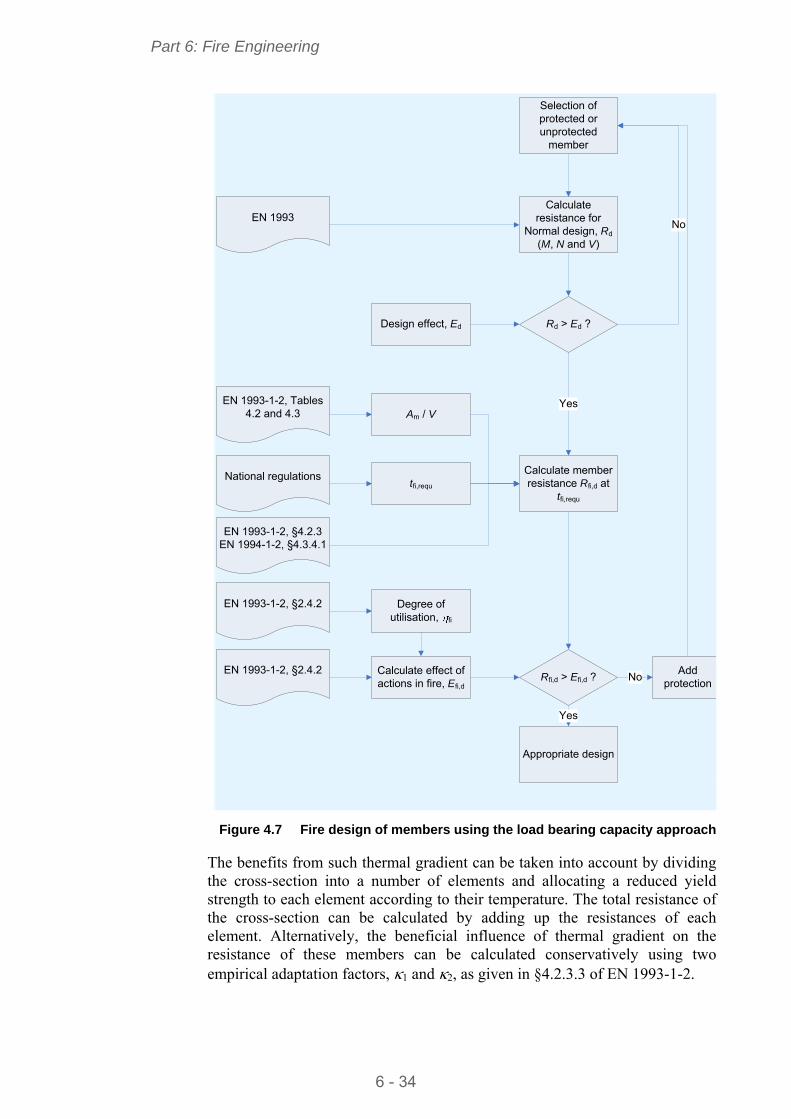
Part 6: Fire Engineering
6 - 34
Selection of protected or unprotected
member
Calculate resistance for
Normal design, Rd
(M, N and V)
Rd > Ed ?
Calculate member resistance Rfi,d at
tfi,requ
Rfi,d > Efi,d ?
Appropriate design
Add protection
Calculate effect of actions in fire, Efi,d
Degree of utilisation, fi
tfi,requ
Am / V
Design effect, Ed
Yes
No
Yes
No
EN 1993
EN 1993-1-2, §4.2.3EN 1994-1-2, §4.3.4.1
EN 1993-1-2, §2.4.2
EN 1993-1-2, §2.4.2
EN 1993-1-2, Tables 4.2 and 4.3
National regulations
Figure 4.7 Fire design of members using the load bearing capacity approach
The benefits from such thermal gradient can be taken into account by dividing the cross-section into a number of elements and allocating a reduced yield strength to each element according to their temperature. The total resistance of the cross-section can be calculated by adding up the resistances of each element. Alternatively, the beneficial influence of thermal gradient on the resistance of these members can be calculated conservatively using two empirical adaptation factors, 1 and 2, as given in §4.2.3.3 of EN 1993-1-2.
Part 6: Fire Engineering
6 - 35
Resistances of unrestrained beams and columns
The simple models for calculating the buckling resistances of unrestrained beams and columns with a uniform temperature are given in §4.2.3.3, §4.2.3.4 and §4.2.3.2 of EN 1993-1-2. These rules were developed by imposing the following modifications on the relevant models given in EN 1993-1-1 for normal design to account for the effect of elevated temperature:
Reduced yield strength for elevated temperature
Use of partial factors for fire design
Increased non-dimensional slenderness
Buckling length of columns in fire is taken as 0,5 and 0,7 of the system length for the top storey and for the other storeys, respectively
Specific buckling curves for the fire condition.
Resistance of composite members in fire
The simple models to calculate the resistances of composite members in fire are given in §4.3 and Annexes D, E, F, G and H of EN 1994-1-2 for composite slabs, composite beams, encased beams, encased columns and filled columns.
Since the temperature generally is not uniformly distributed over the cross-section, the design resistance of a composite member in fire generally has to be calculated by dividing the section into a number of elements. The temperature and the corresponding reduction factors for steel and concrete strengths in each element are determined and the design resistance of all the elements are added to calculate the resistance of the entire cross-section.
The simple models for composite members are more complex than the calculation for bare steel members. For this reason, most calculations for temperature rise and load bearing resistance of composite members are carried out using computer software. In addition, the resistances of many fire design solutions for composite members have been tabulated, as given in §4.2 of EN 1994-1-2.
Resistance of composite slabs
The simple models for fire design of composite slabs are specified in §4.3.1, §4.3.2 and §4.3.3 of EN 1994-1-2. As partition members, composite slabs are required to meet the criteria of insulation ‘I’, integrity ‘E’ and the load bearing resistance ‘R’. These must be demonstrated through fire tests, design calculations or both.
The calculation of sagging and hogging moment resistances of slabs are based on different assumptions and temperature distributions as given in D.2 and D.3 of EN 1994-1-2. The contribution of the steel decking is generally included in the calculation of the sagging moment resistance, but conservatively ignored in the calculation of the hogging moment resistance.
Resistance of composite beams
Composite beams comprise steel sections structurally attached through shear connectors to a concrete or composite slab, with or without concrete encasement. Generally, the voids created by the deck shape over the beam
Part 6: Fire Engineering
6 - 36
flanges are filled, to ensure that the top flange of the steel beam remains relatively cool in fire.
Composite beams may be simply supported or continuous. Their design sagging and hogging moment resistances as well as their vertical and longitudinal shear resistances can be determined by using the simple models given in §4.3.1, §4.3.4 and Annex E of EN 1994-1-2.
Resistance of composite columns
The simple model for buckling resistance of composite columns is based on the assumption that the building is braced and the column has no horizontal displacement. The calculation rules are given in §4.3.5 and Annexes G and H of EN 1994-1-2.
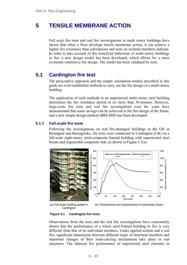
Part 6: Fire Engineering
6 - 37
5 TENSILE MEMBRANE ACTION
Full scale fire tests and real fire investigations in multi storey buildings have shown that when a floor develops tensile membrane action, it can achieve a higher fire resistance than calculations and tests on isolated members indicate. In order to take account of this beneficial behaviour of multi-storey buildings in fire, a new design model has been developed, which allows for a more economic solution to fire design. The model has been validated by tests.
5.1 Cardington fire test The prescriptive approach and the simple calculation models described in this guide are well-established methods to carry out the fire design of a multi-storey building.
The application of such methods to an unprotected multi-storey steel building determines the fire resistance period as no more than 30 minutes. However, large-scale fire tests and real fire investigations over the years have demonstrated that some savings can be achieved in the fire design of the frame, and a new simple design method (BRE-BM) has been developed.
5.1.1 Full-scale fire tests
Following the investigations on real fire-damaged buildings in the UK at Broadgate and Basingstoke, fire tests were conducted in Cardington (UK) on a full-scale eight-storey steel-composite framed building with unprotected steel beams and trapezoidal composite slab, as shown in Figure 5.1(a).
0 50 100 150 200 250 300 3500
100
200
300
400
500
600
0
200
400
600
800
1000
1200
Time (mins)
Ma
xim
um v
ertic
al d
ispl
ace
me
nt (
mm
)
Ma
xim
um s
teel
tem
per
atu
re (
°C)
Maximum vertical displacement Maximum temperature
(a) Full-scale building tested in Cardington
(b) Temperature and displacement of secondary beam
Figure 5.1 Cardington fire tests
Observations from the tests and the real fire investigations have consistently shown that the performance of a whole steel-framed building in fire is very different from that of its individual members. Under applied actions and a real fire, significant interactions between different types of structural members and important changes of their load-carrying mechanisms take place in real structures. The inherent fire performance of unprotected steel elements in
Part 6: Fire Engineering
6 - 38
framed buildings, even in severe fires, is much better than standard fire tests would demonstrate.
As shown in Figure 5.1(b), instead of full collapse, as expected from the standard fire tests, a typical secondary beam in the Cardington fire test maintained its stability even when its temperature reached 954C. Its vertical displacement reached 428 mm at its peak temperature of 954C and recovered to a permanent displacement of 296 mm after the cooling phase. This indicates that there are large reserves of fire resistance in steel-framed buildings. The amount of fire protection being applied to steel elements may, in some cases, be excessive and unnecessary.
The main reason for the above large reserves of fire resistance of multi-storey framed buildings comes from the tensile membrane action of their steel-composite floors, as shown in Figure 5.2 and explained below.
Figure 5.2 Membrane action in a horizontally restrained concrete slab
As described in the Section 4, the simple calculation models for fire design deal with each individual member. These simple models assume the floor slab to be a one-way spanning beam, resisting actions through bending and shear. Observations of the Cardington tests, however, show that as the steel beams lose their load bearing capacity, the composite slab utilises its full bending capacity in spanning between the adjacent, cooler members. As its displacement increases, the slab acts as a tensile membrane, carrying loads in tension, as shown in Figure 5.3.
If the slab is well supported against its vertical deflection along lines which divide it into reasonably square areas, for example, by the primary and secondary beams on the column grid-lines, then tensile membrane action can be generated as a load bearing mechanism. The slab is then forced into double-curvature and hangs as a tensile membrane in its middle regions. A peripheral compressive ‘ring-beam’ is generated either around its supported periphery or in its edge-beams, as shown in Figure 5.2.
Compression
Compression
zone (‘ring’)
zone (‘ring’)
Tension zone
Tension zone
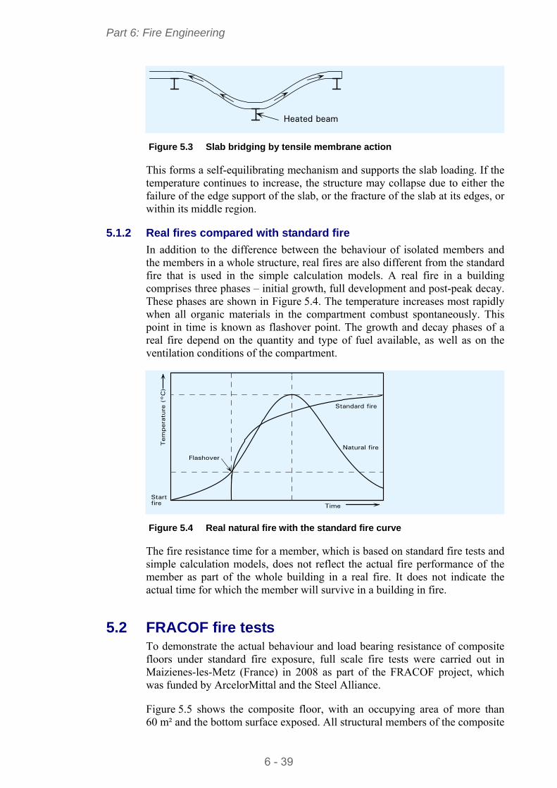
Part 6: Fire Engineering
6 - 39
Heated beam Figure 5.3 Slab bridging by tensile membrane action
This forms a self-equilibrating mechanism and supports the slab loading. If the temperature continues to increase, the structure may collapse due to either the failure of the edge support of the slab, or the fracture of the slab at its edges, or within its middle region.
5.1.2 Real fires compared with standard fire
In addition to the difference between the behaviour of isolated members and the members in a whole structure, real fires are also different from the standard fire that is used in the simple calculation models. A real fire in a building comprises three phases – initial growth, full development and post-peak decay. These phases are shown in Figure 5.4. The temperature increases most rapidly when all organic materials in the compartment combust spontaneously. This point in time is known as flashover point. The growth and decay phases of a real fire depend on the quantity and type of fuel available, as well as on the ventilation conditions of the compartment.
Flashover
Standard fire
Natural fire
Startfire Time
Tem
pera
ture
(°C
)
Figure 5.4 Real natural fire with the standard fire curve
The fire resistance time for a member, which is based on standard fire tests and simple calculation models, does not reflect the actual fire performance of the member as part of the whole building in a real fire. It does not indicate the actual time for which the member will survive in a building in fire.
5.2 FRACOF fire tests To demonstrate the actual behaviour and load bearing resistance of composite floors under standard fire exposure, full scale fire tests were carried out in Maizienes-les-Metz (France) in 2008 as part of the FRACOF project, which was funded by ArcelorMittal and the Steel Alliance.
Figure 5.5 shows the composite floor, with an occupying area of more than 60 m² and the bottom surface exposed. All structural members of the composite
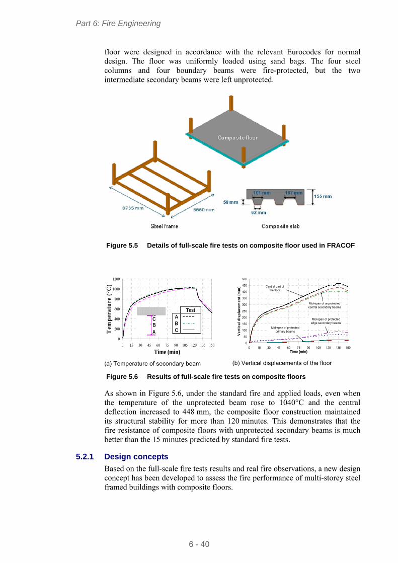
Part 6: Fire Engineering
6 - 40
floor were designed in accordance with the relevant Eurocodes for normal design. The floor was uniformly loaded using sand bags. The four steel columns and four boundary beams were fire-protected, but the two intermediate secondary beams were left unprotected.
Figure 5.5 Details of full-scale fire tests on composite floor used in FRACOF
0
200
400
600
800
1000
1200
0 15 30 45 60 75 90 105 120 135 150
Time (min)
Tem
per
atur
e (°
C)
C B A
Test ABC
(a) Temperature of secondary beam
0
50
100
150
200
250
300
350
400
450
500
0 15 30 45 60 75 90 105 120 135 150Time (min)
Ve
rtic
al d
isp
lac
eme
nt
(mm
) Central part of the floor
Mid-span of unprotected central secondary beams
Mid-span of protected edge secondary beams
Mid-span of protected primary beams
(b) Vertical displacements of the floor
Figure 5.6 Results of full-scale fire tests on composite floors
As shown in Figure 5.6, under the standard fire and applied loads, even when the temperature of the unprotected beam rose to 1040°C and the central deflection increased to 448 mm, the composite floor construction maintained its structural stability for more than 120 minutes. This demonstrates that the fire resistance of composite floors with unprotected secondary beams is much better than the 15 minutes predicted by standard fire tests.
5.2.1 Design concepts
Based on the full-scale fire tests results and real fire observations, a new design concept has been developed to assess the fire performance of multi-storey steel framed buildings with composite floors.
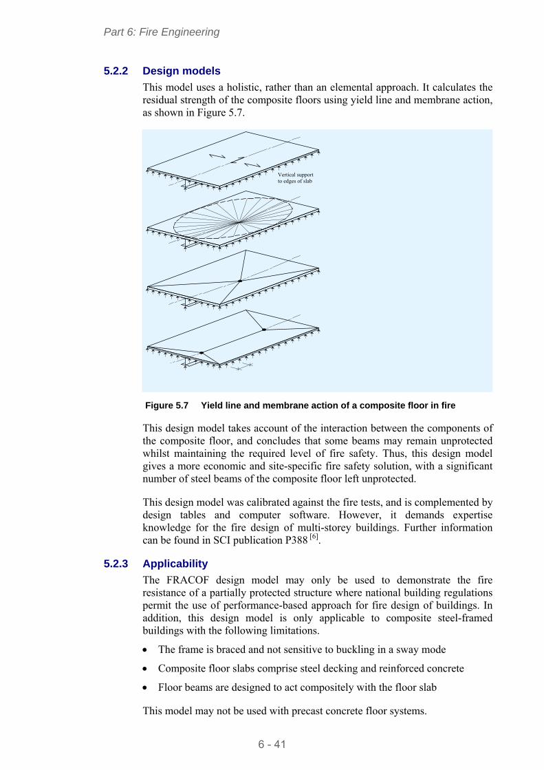
Part 6: Fire Engineering
6 - 41
5.2.2 Design models
This model uses a holistic, rather than an elemental approach. It calculates the residual strength of the composite floors using yield line and membrane action, as shown in Figure 5.7.
Figure 5.7 Yield line and membrane action of a composite floor in fire
This design model takes account of the interaction between the components of the composite floor, and concludes that some beams may remain unprotected whilst maintaining the required level of fire safety. Thus, this design model gives a more economic and site-specific fire safety solution, with a significant number of steel beams of the composite floor left unprotected.
This design model was calibrated against the fire tests, and is complemented by design tables and computer software. However, it demands expertise knowledge for the fire design of multi-storey buildings. Further information can be found in SCI publication P388 [ 6].
5.2.3 Applicability
The FRACOF design model may only be used to demonstrate the fire resistance of a partially protected structure where national building regulations permit the use of performance-based approach for fire design of buildings. In addition, this design model is only applicable to composite steel-framed buildings with the following limitations.
The frame is braced and not sensitive to buckling in a sway mode
Composite floor slabs comprise steel decking and reinforced concrete
Floor beams are designed to act compositely with the floor slab
This model may not be used with precast concrete floor systems.
Vertical supportto edges of slab
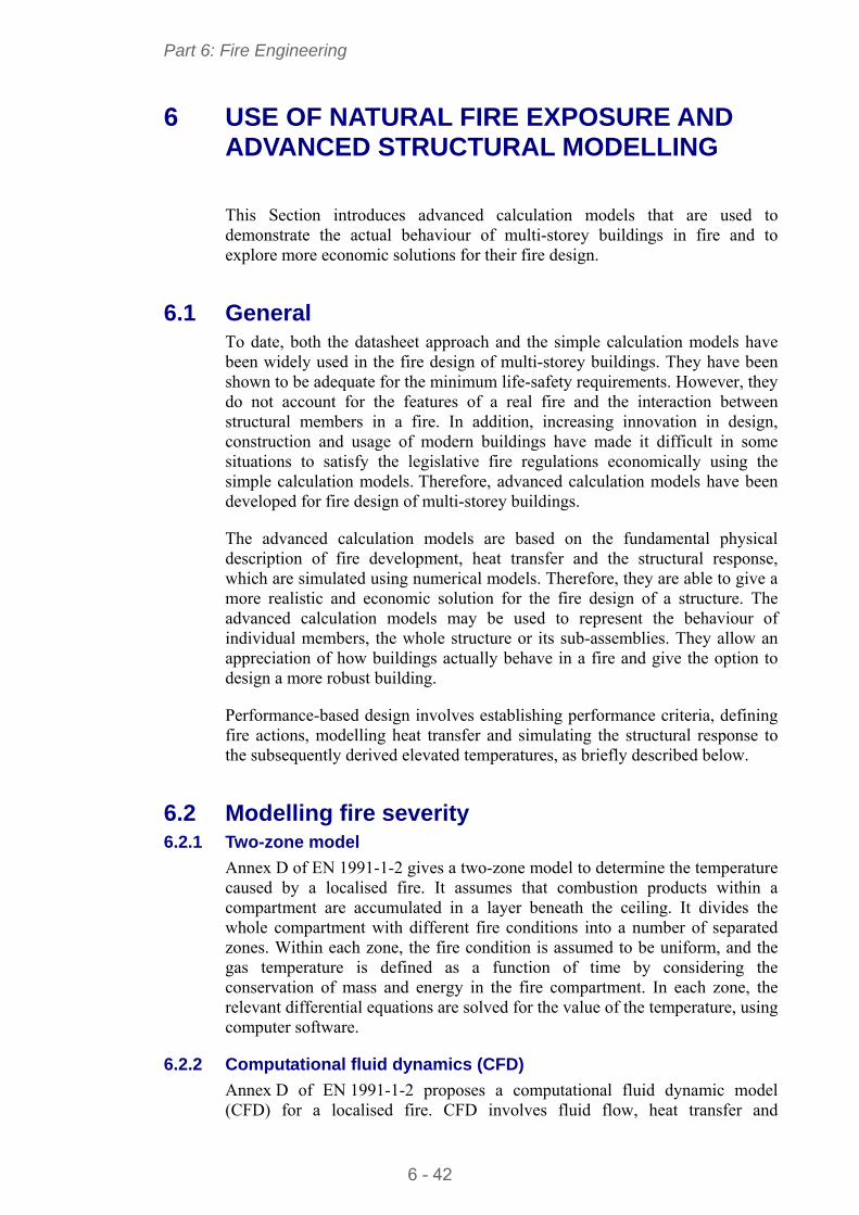
Part 6: Fire Engineering
6 - 42
6 USE OF NATURAL FIRE EXPOSURE AND ADVANCED STRUCTURAL MODELLING
This Section introduces advanced calculation models that are used to demonstrate the actual behaviour of multi-storey buildings in fire and to explore more economic solutions for their fire design.
6.1 General To date, both the datasheet approach and the simple calculation models have been widely used in the fire design of multi-storey buildings. They have been shown to be adequate for the minimum life-safety requirements. However, they do not account for the features of a real fire and the interaction between structural members in a fire. In addition, increasing innovation in design, construction and usage of modern buildings have made it difficult in some situations to satisfy the legislative fire regulations economically using the simple calculation models. Therefore, advanced calculation models have been developed for fire design of multi-storey buildings.
The advanced calculation models are based on the fundamental physical description of fire development, heat transfer and the structural response, which are simulated using numerical models. Therefore, they are able to give a more realistic and economic solution for the fire design of a structure. The advanced calculation models may be used to represent the behaviour of individual members, the whole structure or its sub-assemblies. They allow an appreciation of how buildings actually behave in a fire and give the option to design a more robust building.
Performance-based design involves establishing performance criteria, defining fire actions, modelling heat transfer and simulating the structural response to the subsequently derived elevated temperatures, as briefly described below.
6.2 Modelling fire severity 6.2.1 Two-zone model
Annex D of EN 1991-1-2 gives a two-zone model to determine the temperature caused by a localised fire. It assumes that combustion products within a compartment are accumulated in a layer beneath the ceiling. It divides the whole compartment with different fire conditions into a number of separated zones. Within each zone, the fire condition is assumed to be uniform, and the gas temperature is defined as a function of time by considering the conservation of mass and energy in the fire compartment. In each zone, the relevant differential equations are solved for the value of the temperature, using computer software.
6.2.2 Computational fluid dynamics (CFD)
Annex D of EN 1991-1-2 proposes a computational fluid dynamic model (CFD) for a localised fire. CFD involves fluid flow, heat transfer and
Part 6: Fire Engineering
6 - 43
associated phenomena. It uses a series of partial differential equations to determine the temperature within the compartment due to a localised fire. The CFD model is very demanding and requires expertise to define the input parameters and to assess the appropriateness of the results.
6.2.3 Fully developed fire
The definition of the fully developed fire is given in Section 4.1.3, where the description of the standard fire and the parametric fire are also given. These fire curves are applicable to advanced models as well as to simple methods.
6.3 Modelling heat transfer The temperature rise of a structural member in fire is due to the heat transfer from the gas in the compartment to the member. The temperature rise of a structural member in fire is predominantly controlled by radiation and convection.
Advanced models aim to provide a more realistic solution of temperature rise over the section of a structural member. Advanced models consider:
Thermal actions given in EN 1991-1-2
Non-uniform thermal exposure
Non-uniform heat transfer
Time-dependant boundary conditions
Time and temperature-dependant material properties.
Advanced heat transfer models are developed based on 2D or 3D finite difference or finite element techniques. Therefore, they can only be performed by using commercial computer software packages.
6.4 Advanced structural models Advanced models for structural responses to both the thermal actions and the applied actions are based on the fundamentals of structural engineering and carried out by means of finite element techniques.
The structure under consideration is generally divided into numerous small 2D or 3D elements with different initial and boundary conditions. Although finite element simulation clearly presents significant information to the designer, such an approach should not be taken without due care. There are potential problems associated with:
The choice of software
The options set within the software
The way the structure is modelled
The acceptance criteria used.
Part 6: Fire Engineering
6 - 44
6.5 Validation/verification of advanced models Since a number of advanced calculation models are available to model fire action as well as the thermal and structural response of buildings, both validation and verification must be performed to ensure that a sensible solution is obtained.
Validation is the demonstration of the suitability of the design model or approach for the intended purpose, which includes those for predictions of fire severity, heat transfer and structural response.
Verification is the assessment of whether or not the design model has produced valid results. It includes a careful check on the input data, on the consistence between the results obtained from the model and the results anticipated on qualitative analysis, and on the degrees of risk associated with possible errors. Advanced models should be verified against relevant test results and other calculation methods. They should be checked for compliance with normal engineering principles by the use of sensitivity studies.
In the context of validation and verification of models and results, the standard ISO 16730[ 7] provides a framework for assessment, verification and validation of all types of calculation methods used as tools for fire safety engineering. This international standard does not address specific fire models, but is intended to be applicable to both simple methods and advanced methods.
6.6 Regulatory approval The complexity of obtaining regulatory approval will vary from country to country. However, regulatory bodies may require the designer to present a fire design in a form that may be easily checked by a third party, with each design step clearly documented, including any assumptions and approximations that have been made. A checklist should be produced that covers the overall design approach, the fire model, the heat transfer and the structural response.
Part 6: Fire Engineering
6 - 45
REFERENCES
1. Council directive of 21 Dec 1988, On the approximation of laws, regulations and administrative provisions of the member states relating to construction products, 89/106/EEC.
2. EN 1991-1-2:2002 Eurocode 1. Actions on structures. General actions. Actions on structures exposed to fire
3. EN 1993-1-2:2005 Eurocode 3. Design of steel structures. General rules. Structural fire design
4. EN 1994-1-2:2005 Eurocode 4. Design of composite steel and concrete structures. General rules. Structural fire design
5. EN 13381 Test methods for determining the contribution to the fire resistance of structural members. EN13381-4 Applied passive protection to steel members EN13381-8 Applied reactive protection to steel members (both Parts to be published in 2010)
6. SIMMS, W. I. and ZHAO, B Fire resistance assessment of partially protected composite floors (FRACOF) design guide (P388) The Steel Construction Institute, 2009.
7. ISO 16730: 2008 EDTN1, Fire safety engineering - Assessment, verification and validation of calculation methods
FURTHER READING
1. One stop shop in structural fire engineering http://www.mace.manchester.ac.uk/project/research/structures/strucfire/
2. Test methods for determining the contribution to the fire resistance of structural members. Applied protection to steel members
3. Introduction to fire safety of structures Institution of Structural Engineers,2003
4. HAM, S. J., NEWMAN, G. M., SMITH, C. I. and NEWMAN, L. C. Structural fire safety - A handbook for architects and engineers (P197) The Steel Construction Institute, 1999
5. British Automatic Sprinkler Association Ltd (BASA), Information file, sprinklers in warehouse, http://www.bafsa.org.uk/snews.php (accessed on 24th June, 2009).
6. ECCS, Fire design information sheets, Publication NO.82, Brussels, 1997
7. KIRBY, B. R. Fire resistance of steel structure British Steel, 1991
8. Fire protection for structural steel in buildings (4th edition ) Association for specialist fire protection, 2008
9. Fire resistance of steel-framed buildings Corus, 2006
Part 6: Fire Engineering
6 - 46
10. LAWSON, R. M. and NEWMAN, G. M. Structural fire design to EC3 and EC4, and comparison with BS 5950 (P159) The Steel Construction Institute, 1996
11. RACKHAM, J. W., COUCHMAN, G. H. and HICKS, S. J. Composite slabs and beams using steel decking: Best practice for design and construction - Revised edition (P300), The Steel Construction Institute, 2009
12. LAWSON, R. M. Design of composite slab (P055) The Steel Construction Institute, 1989
13. Comflor®, Composite floor decks Corus, 2007
14. LAWSON, R. M. , MULLETT, D. L. and RACKHAM, J. W. Design of asymmetric slimflor beam using deep composite decking (P175) The Steel Construction Institute, 1997
15. MULLETT, D. L. and LAWSON, R .M. Design of slimflor fabricated beam using deep composite decking (P248) The Steel Construction Institute, 1999
16. MULLETT, D. L. Slim floor design and construction (P110) The Steel Construction Institute, 1992
17. MULLETT, D. L. Design of RHS Slimflor edge beam (P169) The Steel Construction Institute, 1992
18. BAILEY, C. G, NEWMAN, G. M, and SIMMS, W. I. Design of steel framed buildings without applied fire protection (P186) The Steel Construction Institute, 1999
19. LAWSON, R. M. and O’BRIEN, T. Fire safety of external steelwork (P009) The Steel Construction Institute, 1981
20. NEWMAN, G. M., ROBINSON, J. T. and BAILEY, C. G, Fire safe design: A new approach to multi-storey steel-framed buildings - Second Edition (P288) The Steel Construction Institute, 2006
21. BAILEY, C. G. and MOORE, D. B. The structural behaviour of steel frames with composite floor slabs subject to fire, Part 1: Theory The Structural Engineer, 2000
22. BAILEY, C. G. and MOORE, D. B. The structural behaviour of steel frames with composite floor slabs subject to fire, Part 2: Design The Structural Engineer, 2000
23. ZHAO, B. ROOSEFID, M. and VASSART, O. Full scale test of a steel and concrete composite floor exposed to ISO fire and corresponding numerical investigation Eurosteel Conference 2008, 5th European conference on steel and composite structures, Graz, Austria, 2008
Part 6: Fire Engineering
6 - 47
24. PURKISS, J. A. Fire safety engineering design of structures Butterworth-Heineman, 1996
25. BAILEY, C. G and MOORE, D. B. Membrane action of slab/beam composite floor systems in fire Engineering Structures 26, Elsevier,2004
26. Guide to the advanced fire safety of structures Institution of Structural Engineers, 2007

Part 6: Fire Engineering
6 - 48
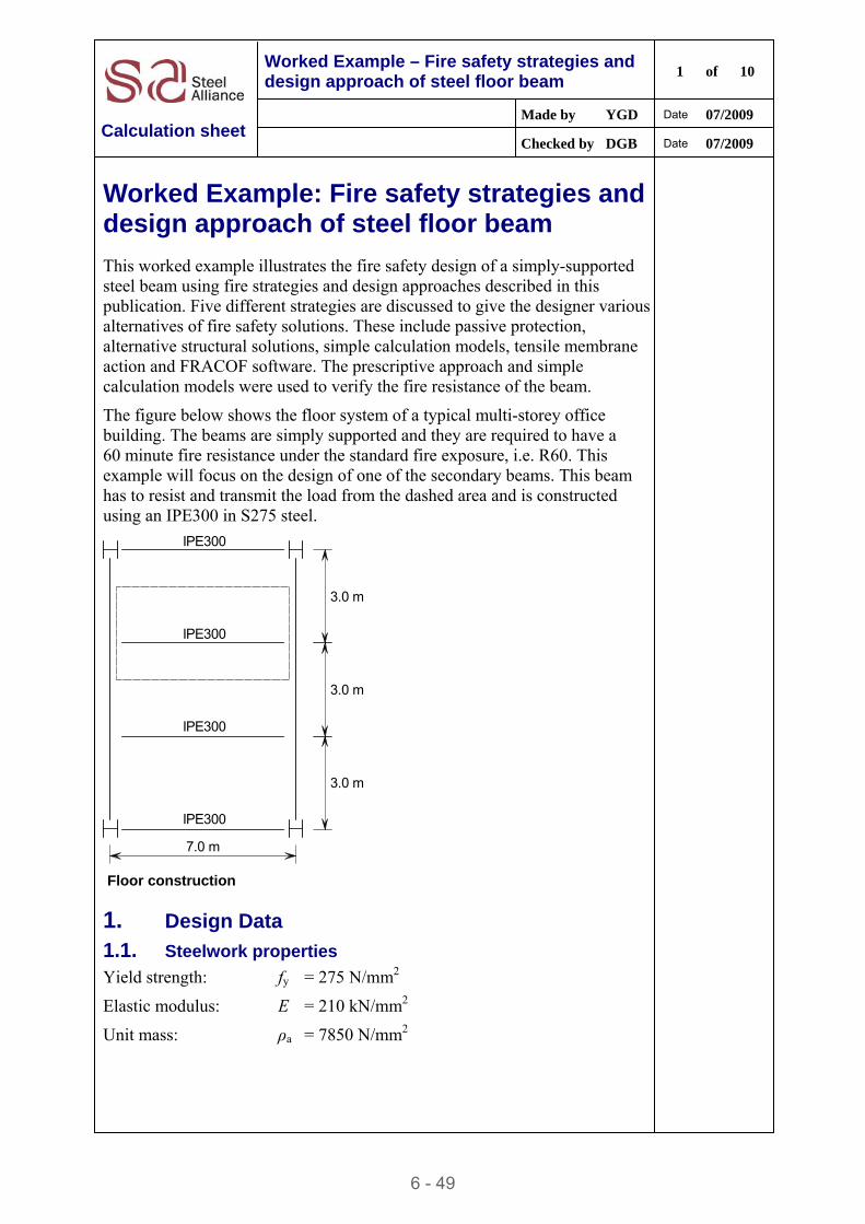
6 - 49
Worked Example – Fire safety strategies and design approach of steel floor beam
1 of 10
Made by YGD Date 07/2009
Calculation sheet Checked by DGB Date 07/2009
Worked Example: Fire safety strategies and design approach of steel floor beam
This worked example illustrates the fire safety design of a simply-supported steel beam using fire strategies and design approaches described in this publication. Five different strategies are discussed to give the designer various alternatives of fire safety solutions. These include passive protection, alternative structural solutions, simple calculation models, tensile membrane action and FRACOF software. The prescriptive approach and simple calculation models were used to verify the fire resistance of the beam.
The figure below shows the floor system of a typical multi-storey office building. The beams are simply supported and they are required to have a 60 minute fire resistance under the standard fire exposure, i.e. R60. This example will focus on the design of one of the secondary beams. This beam has to resist and transmit the load from the dashed area and is constructed using an IPE300 in S275 steel.
7.0 m
IPE300
IPE300
IPE300
IPE300
3.0 m
3.0 m
3.0 m
Floor construction
1. Design Data
1.1. Steelwork properties
Yield strength: fy = 275 N/mm2
Elastic modulus: E = 210 kN/mm2
Unit mass: ρa = 7850 N/mm2
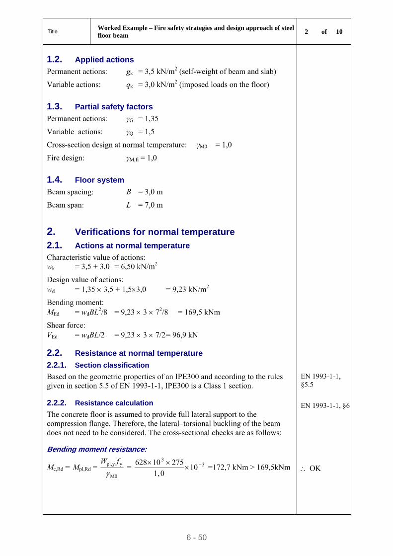
Title Worked Example – Fire safety strategies and design approach of steel floor beam
2 of 10
6 - 50
1.2. Applied actions
Permanent actions: gk = 3,5 kN/m2 (self-weight of beam and slab)
Variable actions: qk = 3,0 kN/m2 (imposed loads on the floor)
1.3. Partial safety factors
Permanent actions: γG = 1,35
Variable actions: γQ = 1,5
Cross-section design at normal temperature: γM0 = 1,0
Fire design: γM,fi = 1,0
1.4. Floor system
Beam spacing: B = 3,0 m
Beam span: L = 7,0 m
2. Verifications for normal temperature
2.1. Actions at normal temperature
Characteristic value of actions: wk = 3,5 + 3,0 = 6,50 kN/m2
Design value of actions: wd = 1,35 3,5 + 1,53,0 = 9,23 kN/m2
Bending moment: MEd = wdBL2/8 = 9,23 3 72/8 = 169,5 kNm
Shear force: VEd = wdBL/2 = 9,23 3 7/2 = 96,9 kN
2.2. Resistance at normal temperature
2.2.1. Section classification
Based on the geometric properties of an IPE300 and according to the rules given in section 5.5 of EN 1993-1-1, IPE300 is a Class 1 section.
EN 1993-1-1, §5.5
2.2.2. Resistance calculation EN 1993-1-1, §6The concrete floor is assumed to provide full lateral support to the compression flange. Therefore, the lateral–torsional buckling of the beam does not need to be considered. The cross-sectional checks are as follows:
Bending moment resistance:
Mc,Rd = Mpl,Rd = M0
yypl,
fW
= 33
100,1
27510628
=172,7 kNm > 169,5kNm OK
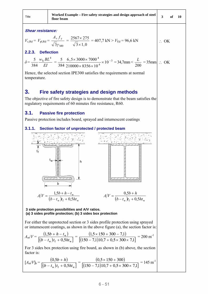
Title Worked Example – Fire safety strategies and design approach of steel floor beam
3 of 10
6 - 51
Shear resistance:
Vc,Rd = Vpl,Rd = M0
yv
3
fA =
0,13
2752567
= 407,7 kN > VEd = 96,6 kN OK
2.2.3. Deflection
δ = EI
BLw 4k
384
5 = 3
4
4
10108356210000
700030005,6
384
5
= 34,7mm <
200
L = 35mm OK
Hence, the selected section IPE300 satisfies the requirements at normal temperature.
3. Fire safety strategies and design methods
The objective of fire safety design is to demonstrate that the beam satisfies the regulatory requirements of 60 minutes fire resistance, R60.
3.1. Passive fire protection
Passive protection includes board, sprayed and intumescent coatings
3.1.1. Section factor of unprotected / protected beam
b
t
t
w
f
h
wfw
w
5,0
5,1
htttb
thbVA
wfw 5,0
5,0
htttb
hbVA
3 side protection possibilities and A/V ratios. (a) 3 sides profile protection; (b) 3 sides box protection
For either the unprotected section or 3 sides profile protection using sprayed or intumescent coatings, as shown in the above figure (a), the section factor is:
Am/V =
wfw
w
5,05,1
htttbthb
=
1,73005,07,101,71501,73001505,1
= 200 m-1
For 3 sides box protection using fire board, as shown in (b) above, the section factor is:
[Am/V]b =
wfw 5,05,0
htttbhb
=
1,73005,07,101,71503001505,0
= 145 m-1
Title Worked Example – Fire safety strategies and design approach of steel floor beam
4 of 10
6 - 52
3.1.2. Fire protection boards
The section factor of the beam section
Am/V = 200 m-1 < [Am/V]max = 260 m-1
20mm thick fire board is adequate for R60. Table 3.1
3.1.3. Sprayed coatings
Am/V = 200 m-1, 16mm thick sprayed coating is adequate for R60. Table 3.2
3.1.4. Intumescent coatings
Am/V =200 m-1, 0,69 mm thick intumescent coating is adequate for R60. Table 3.3
3.2. Alternative structural solutions
To avoid the costs of protection materials and reduce the cost of construction, it is preferred to use unprotected sections, as long as the R60 requirement is satisfied, by using alternative structural solutions. These include encasing the beam in concrete or using a composite slab. These options are discussed in the sections that follow.
3.2.1. Partially encased beam
Load level: ηfi = 0,477 < 0,5
Section ratio: h/b = 300/150 = 2,0 > 1,5.
Hence, for R60 fire resistance, a partially encased beam using concrete without reinforcement can satisfy the R60 requirement.
Note that the extra weight of the concrete should be added to the permanent action.
Table 3.7
3.2.2. Integrated beams
Integrated construction makes use of asymmetric steel sections containing the steel beam within the depth of the precast concrete slab. This solution may satisfy the R60 requirement without the need of fire protection.
Section 3.3.2
3.3. Simple calculation models
To verify the fire resistance of the beam at its fire ultimate limit state, the simple model given in EN 1993-1-1 is used, following the flowchart given in Section 4.4 of this publication. This model is applied to unprotected sections and to sections protected with fire boards.
The next section presents the calculation using the load bearing resistance approach. In order to obtain an optimised design, the worked example uses different protection thicknesses until the optimal is found.
The critical calculation approach can only be used when the temperature across the cross-section is uniform and it is not shown in this example.
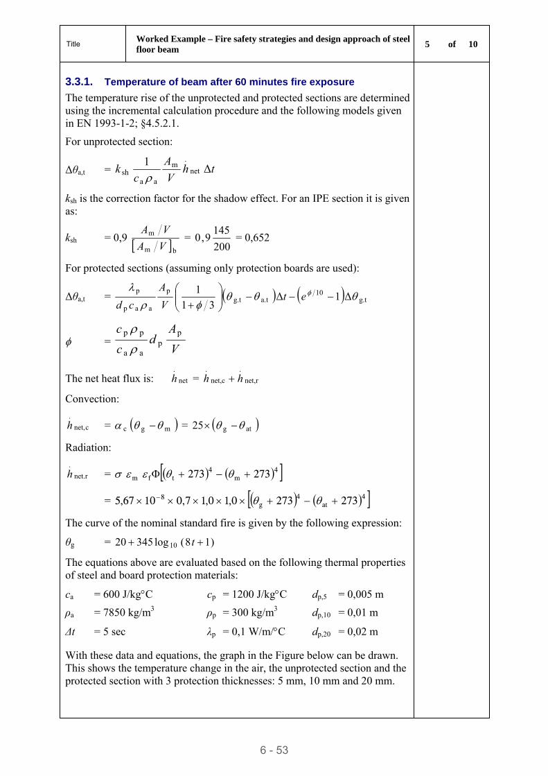
Title Worked Example – Fire safety strategies and design approach of steel floor beam
5 of 10
6 - 53
3.3.1. Temperature of beam after 60 minutes fire exposure
The temperature rise of the unprotected and protected sections are determined using the incremental calculation procedure and the following models given in EN 1993-1-2; §4.5.2.1.
For unprotected section:
Δθa,t = thV
A
ck Δ
1net
.m
aash
ksh is the correction factor for the shadow effect. For an IPE section it is given as:
ksh = 0,9 bm
m
VA
VA =
200
1459,0 = 0,652
For protected sections (assuming only protection boards are used):
Δθa,t = g.t10
a.tg.tp
aap
pΔ1Δ
31
1
etV
A
cd
= V
Ad
c
c pp
aa
pp
The net heat flux is: net
.
h = rnet,
.
net,c
.
hh
Convection:
cnet,
.
h = mgc = atg25
Radiation:
net.r
.
h = 4m
4tfm 273273
= 4at
4g
8 2732730,10,17,01067,5
The curve of the nominal standard fire is given by the following expression:
θg = )18(log34520 10 t
The equations above are evaluated based on the following thermal properties of steel and board protection materials:
ca = 600 J/kgC cp = 1200 J/kgC dp,5 = 0,005 m
ρa = 7850 kg/m3 ρp = 300 kg/m3 dp,10 = 0,01 m
Δt = 5 sec λp = 0,1 W/m/C dp,20 = 0,02 m
With these data and equations, the graph in the Figure below can be drawn. This shows the temperature change in the air, the unprotected section and the protected section with 3 protection thicknesses: 5 mm, 10 mm and 20 mm.
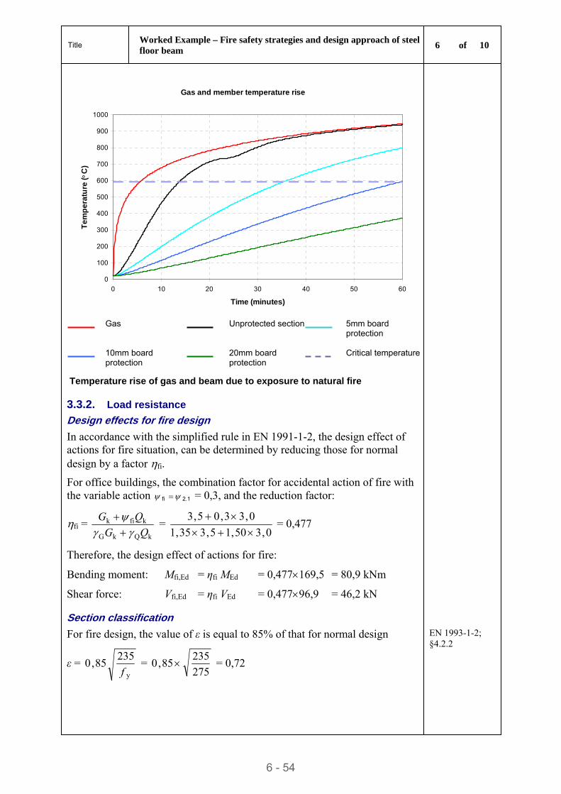
Title Worked Example – Fire safety strategies and design approach of steel floor beam
6 of 10
6 - 54
Gas and member temperature rise
0
100
200
300
400
500
600
700
800
900
1000
0 10 20 30 40 50 60
Time (minutes)
Te
mp
era
ture
(C
)
Gas Unprotected section 5mm board
protection
10mm board protection
20mm board protection
Critical temperature
Temperature rise of gas and beam due to exposure to natural fire
3.3.2. Load resistance
Design effects for fire design
In accordance with the simplified rule in EN 1991-1-2, the design effect of actions for fire situation, can be determined by reducing those for normal design by a factor fi.
For office buildings, the combination factor for accidental action of fire with the variable action 1.2fi = 0,3, and the reduction factor:
fi = kQkG
kfik
QG
QG
=
0,350,15,335,1
0,33,05,3
= 0,477
Therefore, the design effect of actions for fire:
Bending moment: Mfi,Ed = ηfi MEd = 0,477169,5 = 80,9 kNm
Shear force: Vfi,Ed = ηfi VEd = 0,47796,9 = 46,2 kN
Section classification
For fire design, the value of ε is equal to 85% of that for normal design
ε = y
23585,0
f =
275
23585,0 = 0,72
EN 1993-1-2; §4.2.2
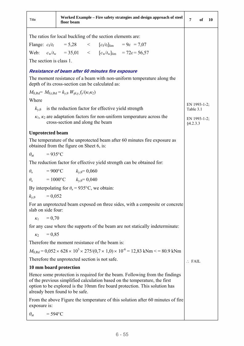
Title Worked Example – Fire safety strategies and design approach of steel floor beam
7 of 10
6 - 55
The ratios for local buckling of the section elements are:
Flange: cf/tf = 5,28 < [cf/tf]lim = 9ε = 7,07
Web: cw/tw = 35,01 < [cw/tw]lim = 72ε = 56,57
The section is class 1.
Resistance of beam after 60 minutes fire exposure
The moment resistance of a beam with non-uniform temperature along the depth of its cross-section can be calculated as:
Mfi,Rd= Mfi,t,Rd = ky,θ Wpl,y fy/(κ1κ2)
Where
ky,θ is the reduction factor for effective yield strength
κ1, κ2 are adaptation factors for non-uniform temperature across the cross-section and along the beam
EN 1993-1-2; Table 3.1 EN 1993-1-2; §4.2.3.3
Unprotected beam
The temperature of the unprotected beam after 60 minutes fire exposure as obtained from the figure on Sheet 6, is:
θat = 935C
The reduction factor for effective yield strength can be obtained for:
θa = 900C ky,θ= 0,060
θa = 1000C ky,θ= 0,040
By interpolating for θa = 935C, we obtain:
ky,θ = 0,052
For an unprotected beam exposed on three sides, with a composite or concrete slab on side four:
κ1 = 0,70
for any case where the supports of the beam are not statically indeterminate:
κ2 = 0,85
Therefore the moment resistance of the beam is:
Mfi,Rd = 0,052 628 103 275/(0,7 1,0) 10-6 = 12,83 kNm < = 80.9 kNm
Therefore the unprotected section is not safe.
FAIL
10 mm board protection
Hence some protection is required for the beam. Following from the findings of the previous simplified calculation based on the temperature, the first option to be explored is the 10mm fire board protection. This solution has already been found to be safe.
From the above Figure the temperature of this solution after 60 minutes of fire exposure is:
θat = 594C
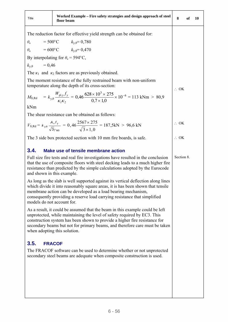
Title Worked Example – Fire safety strategies and design approach of steel floor beam
8 of 10
6 - 56
The reduction factor for effective yield strength can be obtained for:
θa = 500C ky,θ= 0,780
θa = 600C ky,θ= 0,470
By interpolating for θa = 594C,
ky,θ = 0,46
The κ1 and κ2 factors are as previously obtained.
The moment resistance of the fully restrained beam with non-uniform temperature along the depth of its cross-section:
Mfi,Rd = 21
yypl,y,θ
fWk = 6
3
100,17,027510628
46,0
= 113 kNm > 80,9
kNm
OK
The shear resistance can be obtained as follows:
Vfi,Rd = M0
yvy,θ
3
fAk =
0,13
275256746,0
= 187,5kN > 96,6 kN
OK
The 3 side box protected section with 10 mm fire boards, is safe. OK
3.4. Make use of tensile membrane action
Full size fire tests and real fire investigations have resulted in the conclusion that the use of composite floors with steel decking leads to a much higher fire resistance than predicted by the simple calculations adopted by the Eurocode and shown in this example.
Section 8.
As long as the slab is well supported against its vertical deflection along lines which divide it into reasonably square areas, it is has been shown that tensile membrane action can be developed as a load bearing mechanism, consequently providing a reserve load carrying resistance that simplified models do not account for.
As a result, it could be assumed that the beam in this example could be left unprotected, while maintaining the level of safety required by EC3. This construction system has been shown to provide a higher fire resistance for secondary beams but not for primary beams, and therefore care must be taken when adopting this solution.
3.5. FRACOF
The FRACOF software can be used to determine whether or not unprotected secondary steel beams are adequate when composite construction is used.
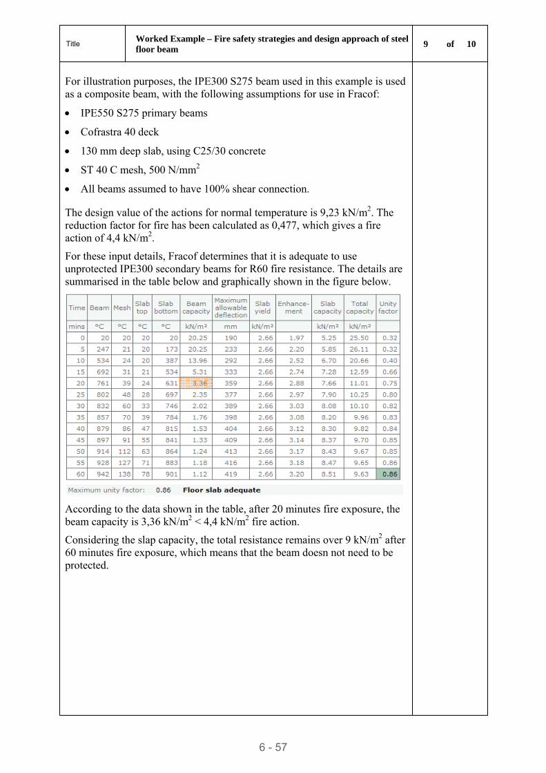
Title Worked Example – Fire safety strategies and design approach of steel floor beam
9 of 10
6 - 57
For illustration purposes, the IPE300 S275 beam used in this example is used as a composite beam, with the following assumptions for use in Fracof:
IPE550 S275 primary beams
Cofrastra 40 deck
130 mm deep slab, using C25/30 concrete
ST 40 C mesh, 500 N/mm2
All beams assumed to have 100% shear connection.
The design value of the actions for normal temperature is 9,23 kN/m2. The reduction factor for fire has been calculated as 0,477, which gives a fire action of 4,4 kN/m2.
For these input details, Fracof determines that it is adequate to use unprotected IPE300 secondary beams for R60 fire resistance. The details are summarised in the table below and graphically shown in the figure below.
According to the data shown in the table, after 20 minutes fire exposure, the beam capacity is 3,36 kN/m2 < 4,4 kN/m2 fire action.
Considering the slap capacity, the total resistance remains over 9 kN/m2 after 60 minutes fire exposure, which means that the beam doesn not need to be protected.
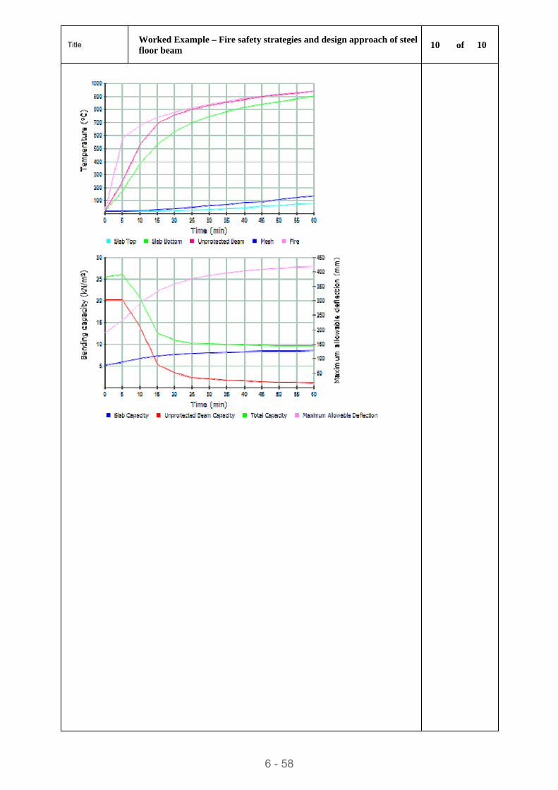
Title Worked Example – Fire safety strategies and design approach of steel floor beam
10 of 10
6 - 58
STEEL BUILDINGS IN EUROPE
Multi-Storey Steel Buildings
Part 7: Model Construction
Specification

Multi-Storey Steel Buildings
Part 7: Model Construction
Specification

7 - ii
Part 7: Model Construction Specification
FOREWORD
This publication is the second part of the design guide, Multi-Storey Steel Buildings.
The 10 parts in the Multi-Storey Steel Buildings guide are:
Part 1: Architect’s guide
Part 2: Concept design
Part 3: Actions
Part 4: Detailed design
Part 5: Joint design
Part 6: Fire Engineering
Part 7: Model construction specification
Part 8: Description of member resistance calculator
Part 9: Description of simple connection resistance calculator
Part 10: Guidance to developers of software for the design of composite beams
Multi-Storey Steel Buildings is one of two design guides. The second design guide is Single-Storey Steel Buildings.
The two design guides have been produced in the framework of the European project “Facilitating the market development for sections in industrial halls and low rise buildings (SECHALO) RFS2-CT-2008-0030”.
The design guides have been prepared under the direction of Arcelor Mittal, Peiner Träger and Corus. The technical content has been prepared by CTICM and SCI, collaborating as the Steel Alliance.
7 - iii

Part 7: Model Construction Specification
7 - iv
Part 7: Model Construction Specification
Contents Page No
FOREWORD iii
SUMMARY vii
1 INTRODUCTION 1 1.1 Scope 2
2 NORMATIVE REFERENCES 4
3 BASIS OF STRUCTURAL DESIGN 9 3.1 General assumptions according to EN 1990 9
4 ACTIONS ON STRUCTURES 10 4.1 Self-weight and imposed loads for buildings 10 4.2 Snow loads 10 4.3 Wind loads 11 4.4 Thermal actions 11 4.5 Actions during execution 11 4.6 Accidental actions 13 4.7 Seismic actions 14
5 DESIGN OF STEEL STRUCTURES 16 5.1 Rules for multi-storey buildings – EN 1993-1-1 16 5.2 Design of joints – EN 1993-1-8 17 5.3 Material toughness and through-thickness properties – EN 1993-1-10 17 5.4 Composite steel and concrete structures – EN 1994-1-1 18
6 EXECUTION SPECIFICATION 19 6.1 General 19 6.2 Execution classes 19 6.3 Preparation grades 19 6.4 Geometrical tolerances 19
7 CONSTITUENT PRODUCTS 21 7.1 Identification, inspection documents and traceability 21 7.2 Structural steel products 21 7.3 Welding consumables 21 7.4 Mechanical fasteners 21 7.5 Grouting materials 21
8 PREPARATION AND ASSEMBLY 22 8.1 Identification 22 8.2 Handling and storage 22 8.3 Cutting 22 8.4 Shaping 22 8.5 Holing 22 8.6 Assembly 22
9 WELDING 23 9.1 General 23 9.2 Qualification of welding procedures 23 9.3 Welders and welding operators 23 9.4 Welding coordination 23 9.5 Preparation and execution of welding 23 9.6 Acceptance criteria 25
7 - v
Part 7: Model Construction Specification
10 MECHANICAL FASTENING 26
11 ERECTION 27
12 CONSTRUCTOR’S DOCUMENTATION 30
13 INTERFACES OF THE STEEL STRUCTURE 31 13.1 Interface to concrete surfaces 31 13.2 Interface to neighbouring constructions 32
Appendix A MODEL PROJECT SPECIFICATION 33
7 - vi
Part 7: Model Construction Specification
SUMMARY
This guide is a Model Construction Specification to be used in contract documents for a typical construction project of a multi-storey building. Its main objectives are to achieve greater uniformity in steelwork contract specifications in Europe and to provide a guide to specification of appropriate standards for the design, fabrication and erection of steelwork structures for buildings.
It deals with structural steelwork designed in accordance with applicable parts of the Eurocode Standards, to be executed in accordance with applicable parts of EN 1090. All the relevant Sections of the model specification are included in an appendix that can be directly copied and used in contracts, with any additional project-specific information that may be required.
7 - vii

Part 7: Model Construction Specification
7 - viii
Part 7: Model Construction Specification
1 INTRODUCTION
This guide is a Model Construction Specification to be used in contract documents for a typical construction project of a multi-storey building. Its main objectives are:
To achieve greater uniformity in steelwork contract specifications in Europe.
To provide a guide to specification of appropriate standards for the design, fabrication and erection of steelwork structures for buildings.
It is essential that the designer and the steelwork contractor receive, on time, all information necessary for them to carry out the contract. This Model Construction Specification gives guidance on the items and information that should be included in the Project Specification.
The Member States of the EU and EFTA recognise that Eurocodes serve as reference documents for the following purposes:
As a means to prove compliance of building and civil engineering works with the essential requirements of Construction Products Directive 89/106/EEC of 21 December 1988 (amended by Directive 93/68/EEC of 22 July 1993), particularly Essential Requirement No. 1 – Mechanical resistance and stability – and Essential Requirement No. 2 – Safety in case of fire.
As a basis for specifying contracts for construction works and related engineering services.
As a framework for drawing up harmonised technical specifications for construction products (ENs and ETAs).
The Eurocodes, as far as they concern the construction works themselves, have a direct relationship with the Interpretative Documents referred to in Article 12 of the Construction Products Directive, although they are of a different nature from harmonised product standards. There is a need for consistency between the harmonised technical specifications for construction products and the technical rules for works.
The steel construction industry in Europe will have to use CE marked products. The performances of these products can be declared by reference to requirements given in:
The harmonised European Standards such as the standards EN 10025 and EN 1090. Parts 1 of these Standards (i.e. EN 10025-1 and EN 1090-1 respectively) include a special Annex ZA relating to CE marking.
A European Technical Approval (ETA).
CE Marking of steel products to EN 10025 has been mandatory since 2006. The use of CE marked products according to EN 1090 will be mandatory from the first semester 2011 for most of the European countries. Once it appears in the European Official Journal, the standard will be in the application phase.
7 - 1
Part 7: Model Construction Specification
In EN 1090-1, for some special types of construction products (modular construction for example), reference is made to the Eurocodes. In this case, it shall be mentioned which Nationally Determined Parameters have been taken into account.
Much of the information noted in this Model Construction Specification is based upon that given in these Standards, but it must not be inferred that the full details of the standards are not relevant.
References to applicable parts of European Standards have been made throughout this Model Construction Specification.
1.1 Scope This Model Construction Specification deals with structural steelwork designed in accordance with applicable parts of the Eurocode Standards and executed in accordance with applicable parts of EN 1090.
It can be used for all types of multi-storey building construction designed for static loading, including cases where the dynamic effects are assessed using equivalent quasi-static loads and dynamic amplification factors, including wind actions and actions induced by hoists and cranes and cranes on runway beams.
It is not intended to be used for steelwork in dynamically loaded structures.
This Model Construction Specification covers structural steelwork produced from hot rolled structural steel products only. It does not cover structural steelwork produced from cold formed structural steel (only cold formed profiled steel sheeting and cold formed stressed-skin sheeting used as a structural diaphragm are herein covered), structural hollow sections, channels and tubes, and stainless steel products.
This Model Construction Specification should be introduced into a steelwork contract by a Project Specification, the contents of which are detailed in Appendix A of this document and completed with project-specific information. The Project Specification should also include any additions or modifications that may be required by the National Structural Steelwork Specification by the Client for a particular contract if the form of behaviour or other aspects of the structure are unorthodox.
Contract documents (which include architectural and/or structural design drawings, specifications and addenda) vary considerably in intricacy and completeness. Nonetheless, the designer, the fabricator and the erector must be able to rely upon the accuracy of the contract documents, in order to allow them to provide the Client with bids that are adequate and complete. It also enables the preparation of the general arrangement drawings and the shop and erection drawings, the ordering of materials and the timely fabrication and erection of construction components.
Critical requirements that are necessary to protect the Client’s interest, that affect the integrity of the structure or that are necessary for the designer, the
7 - 2
Part 7: Model Construction Specification
fabricator and the erector to proceed with their work, must be included in the contract documents. Non-exhaustive examples of critical information include:
Standard specifications and codes that govern structural steel design and construction, including bolting and welding
Material specifications
Welded-joint configuration and weld-procedure qualification
Surface preparation and shop painting requirements
Shop and field inspection requirements
If any, non-destructive testing (NDT) requirements, including acceptance criteria
Special requirements on delivery and special erection limitations.
7 - 3
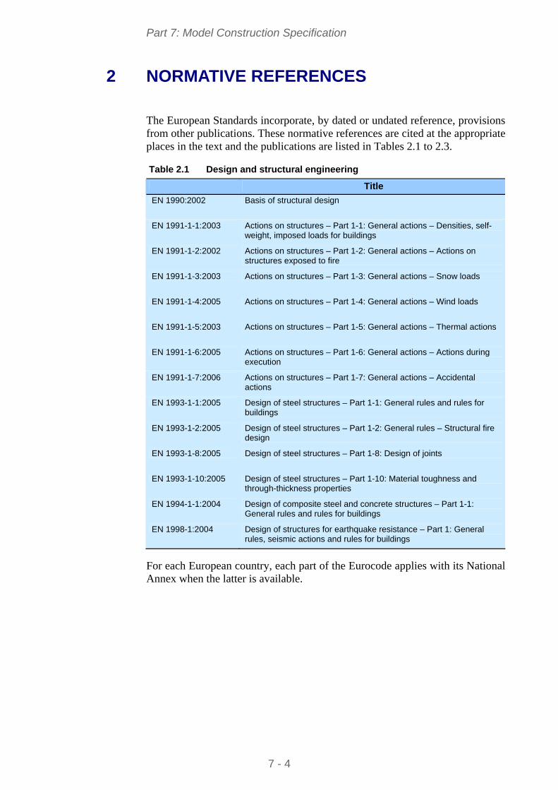
Part 7: Model Construction Specification
2 NORMATIVE REFERENCES
The European Standards incorporate, by dated or undated reference, provisions from other publications. These normative references are cited at the appropriate places in the text and the publications are listed in Tables 2.1 to 2.3.
Table 2.1 Design and structural engineering
Title
EN 1990:2002 Basis of structural design
EN 1991-1-1:2003 Actions on structures – Part 1-1: General actions – Densities, self- weight, imposed loads for buildings
EN 1991-1-2:2002 Actions on structures – Part 1-2: General actions – Actions on structures exposed to fire
EN 1991-1-3:2003 Actions on structures – Part 1-3: General actions – Snow loads
EN 1991-1-4:2005 Actions on structures – Part 1-4: General actions – Wind loads
EN 1991-1-5:2003 Actions on structures – Part 1-5: General actions – Thermal actions
EN 1991-1-6:2005 Actions on structures – Part 1-6: General actions – Actions during execution
EN 1991-1-7:2006 Actions on structures – Part 1-7: General actions – Accidental actions
EN 1993-1-1:2005 Design of steel structures – Part 1-1: General rules and rules for buildings
EN 1993-1-2:2005 Design of steel structures – Part 1-2: General rules – Structural fire design
EN 1993-1-8:2005 Design of steel structures – Part 1-8: Design of joints
EN 1993-1-10:2005 Design of steel structures – Part 1-10: Material toughness and through-thickness properties
EN 1994-1-1:2004 Design of composite steel and concrete structures – Part 1-1: General rules and rules for buildings
EN 1998-1:2004 Design of structures for earthquake resistance – Part 1: General rules, seismic actions and rules for buildings
For each European country, each part of the Eurocode applies with its National Annex when the latter is available.
7 - 4
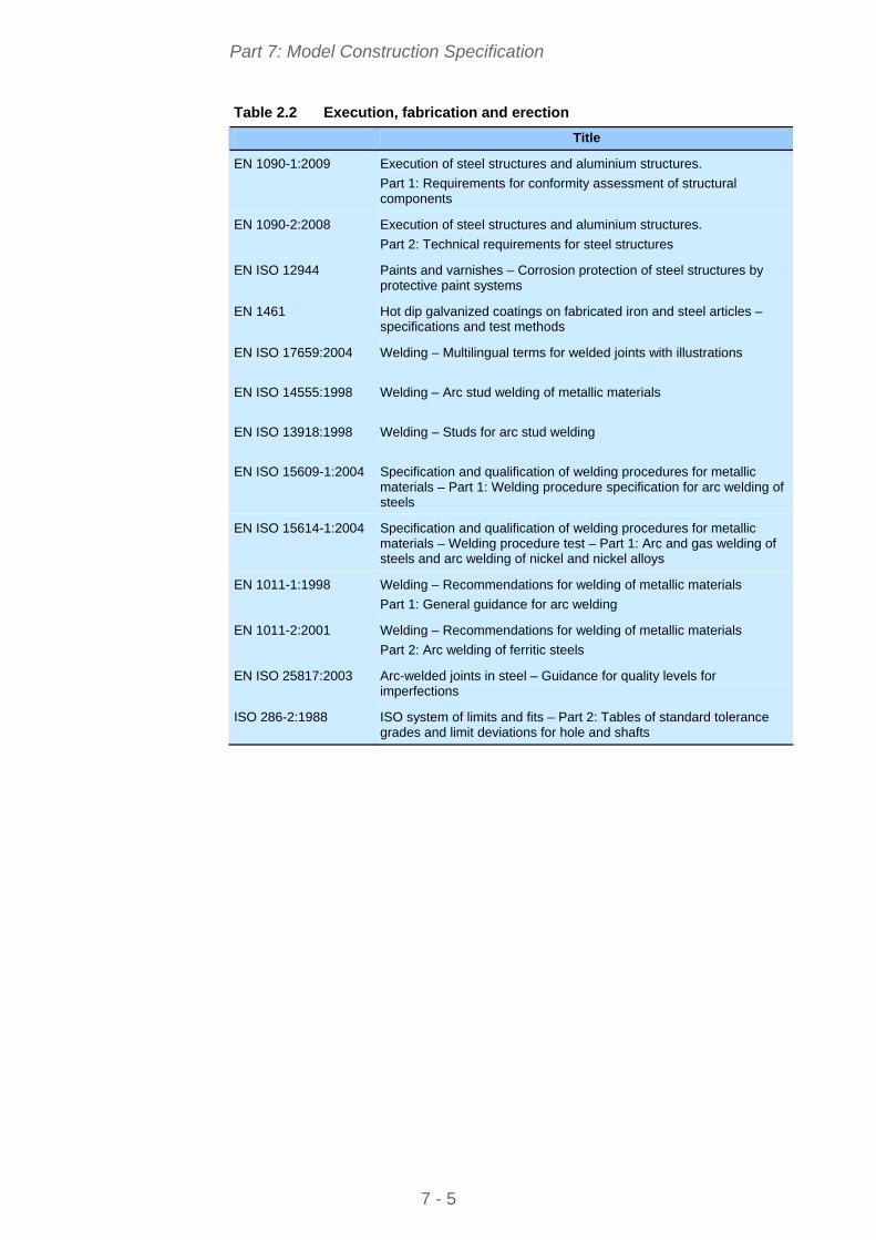
Part 7: Model Construction Specification
Table 2.2 Execution, fabrication and erection
Title
EN 1090-1:2009 Execution of steel structures and aluminium structures.
Part 1: Requirements for conformity assessment of structural components
EN 1090-2:2008 Execution of steel structures and aluminium structures.
Part 2: Technical requirements for steel structures
EN ISO 12944 Paints and varnishes – Corrosion protection of steel structures by protective paint systems
EN 1461 Hot dip galvanized coatings on fabricated iron and steel articles – specifications and test methods
EN ISO 17659:2004 Welding – Multilingual terms for welded joints with illustrations
EN ISO 14555:1998 Welding – Arc stud welding of metallic materials
EN ISO 13918:1998 Welding – Studs for arc stud welding
EN ISO 15609-1:2004 Specification and qualification of welding procedures for metallic materials – Part 1: Welding procedure specification for arc welding of steels
EN ISO 15614-1:2004 Specification and qualification of welding procedures for metallic materials – Welding procedure test – Part 1: Arc and gas welding of steels and arc welding of nickel and nickel alloys
EN 1011-1:1998 Welding – Recommendations for welding of metallic materials
Part 1: General guidance for arc welding
EN 1011-2:2001 Welding – Recommendations for welding of metallic materials
Part 2: Arc welding of ferritic steels
EN ISO 25817:2003 Arc-welded joints in steel – Guidance for quality levels for imperfections
ISO 286-2:1988 ISO system of limits and fits – Part 2: Tables of standard tolerance grades and limit deviations for hole and shafts
7 - 5
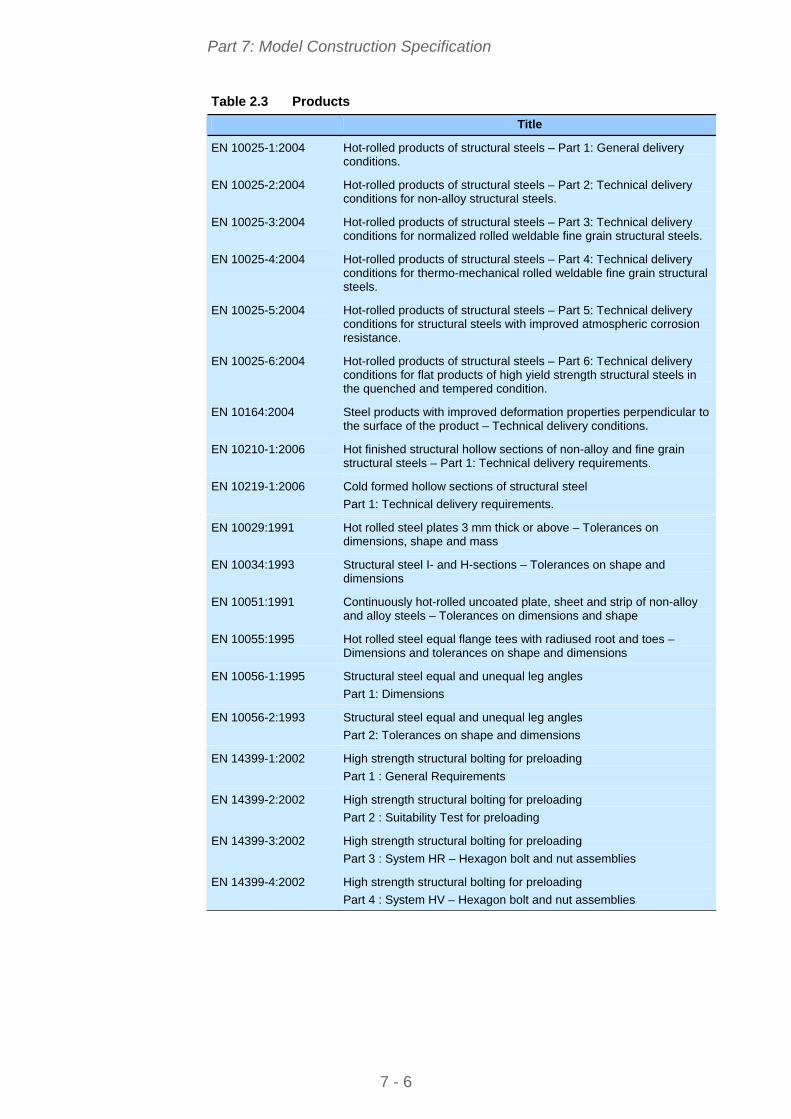
Part 7: Model Construction Specification
Table 2.3 Products
Title
EN 10025-1:2004 Hot-rolled products of structural steels – Part 1: General delivery conditions.
EN 10025-2:2004 Hot-rolled products of structural steels – Part 2: Technical delivery conditions for non-alloy structural steels.
EN 10025-3:2004 Hot-rolled products of structural steels – Part 3: Technical delivery conditions for normalized rolled weldable fine grain structural steels.
EN 10025-4:2004 Hot-rolled products of structural steels – Part 4: Technical delivery conditions for thermo-mechanical rolled weldable fine grain structural steels.
EN 10025-5:2004 Hot-rolled products of structural steels – Part 5: Technical delivery conditions for structural steels with improved atmospheric corrosion resistance.
EN 10025-6:2004 Hot-rolled products of structural steels – Part 6: Technical delivery conditions for flat products of high yield strength structural steels in the quenched and tempered condition.
EN 10164:2004 Steel products with improved deformation properties perpendicular to the surface of the product – Technical delivery conditions.
EN 10210-1:2006 Hot finished structural hollow sections of non-alloy and fine grain structural steels – Part 1: Technical delivery requirements.
EN 10219-1:2006 Cold formed hollow sections of structural steel
Part 1: Technical delivery requirements.
EN 10029:1991 Hot rolled steel plates 3 mm thick or above – Tolerances on dimensions, shape and mass
EN 10034:1993 Structural steel I- and H-sections – Tolerances on shape and dimensions
EN 10051:1991 Continuously hot-rolled uncoated plate, sheet and strip of non-alloy and alloy steels – Tolerances on dimensions and shape
EN 10055:1995 Hot rolled steel equal flange tees with radiused root and toes – Dimensions and tolerances on shape and dimensions
EN 10056-1:1995 Structural steel equal and unequal leg angles
Part 1: Dimensions
EN 10056-2:1993 Structural steel equal and unequal leg angles
Part 2: Tolerances on shape and dimensions
EN 14399-1:2002 High strength structural bolting for preloading
Part 1 : General Requirements
EN 14399-2:2002 High strength structural bolting for preloading
Part 2 : Suitability Test for preloading
EN 14399-3:2002 High strength structural bolting for preloading
Part 3 : System HR – Hexagon bolt and nut assemblies
EN 14399-4:2002 High strength structural bolting for preloading
Part 4 : System HV – Hexagon bolt and nut assemblies
7 - 6
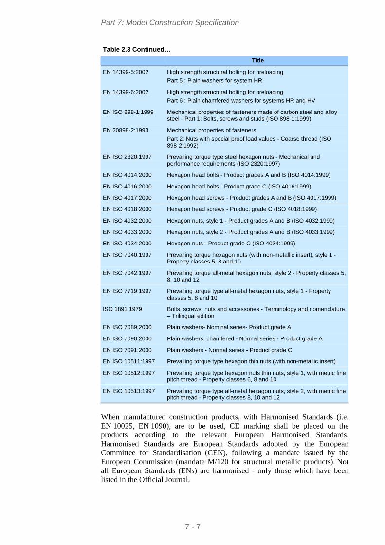
Part 7: Model Construction Specification
Table 2.3 Continued…
Title
EN 14399-5:2002 High strength structural bolting for preloading
Part 5 : Plain washers for system HR
EN 14399-6:2002 High strength structural bolting for preloading
Part 6 : Plain chamfered washers for systems HR and HV
EN ISO 898-1:1999 Mechanical properties of fasteners made of carbon steel and alloy steel - Part 1: Bolts, screws and studs (ISO 898-1:1999)
EN 20898-2:1993 Mechanical properties of fasteners
Part 2: Nuts with special proof load values - Coarse thread (ISO 898-2:1992)
EN ISO 2320:1997 Prevailing torque type steel hexagon nuts - Mechanical and performance requirements (ISO 2320:1997)
EN ISO 4014:2000 Hexagon head bolts - Product grades A and B (ISO 4014:1999)
EN ISO 4016:2000 Hexagon head bolts - Product grade C (ISO 4016:1999)
EN ISO 4017:2000 Hexagon head screws - Product grades A and B (ISO 4017:1999)
EN ISO 4018:2000 Hexagon head screws - Product grade C (ISO 4018:1999)
EN ISO 4032:2000 Hexagon nuts, style 1 - Product grades A and B (ISO 4032:1999)
EN ISO 4033:2000 Hexagon nuts, style 2 - Product grades A and B (ISO 4033:1999)
EN ISO 4034:2000 Hexagon nuts - Product grade C (ISO 4034:1999)
EN ISO 7040:1997 Prevailing torque hexagon nuts (with non-metallic insert), style 1 - Property classes 5, 8 and 10
EN ISO 7042:1997 Prevailing torque all-metal hexagon nuts, style 2 - Property classes 5, 8, 10 and 12
EN ISO 7719:1997 Prevailing torque type all-metal hexagon nuts, style 1 - Property classes 5, 8 and 10
ISO 1891:1979 Bolts, screws, nuts and accessories - Terminology and nomenclature – Trilingual edition
EN ISO 7089:2000 Plain washers- Nominal series- Product grade A
EN ISO 7090:2000 Plain washers, chamfered - Normal series - Product grade A
EN ISO 7091:2000 Plain washers - Normal series - Product grade C
EN ISO 10511:1997 Prevailing torque type hexagon thin nuts (with non-metallic insert)
EN ISO 10512:1997 Prevailing torque type hexagon nuts thin nuts, style 1, with metric fine pitch thread - Property classes 6, 8 and 10
EN ISO 10513:1997 Prevailing torque type all-metal hexagon nuts, style 2, with metric fine pitch thread - Property classes 8, 10 and 12
When manufactured construction products, with Harmonised Standards (i.e. EN 10025, EN 1090), are to be used, CE marking shall be placed on the products according to the relevant European Harmonised Standards. Harmonised Standards are European Standards adopted by the European Committee for Standardisation (CEN), following a mandate issued by the European Commission (mandate M/120 for structural metallic products). Not all European Standards (ENs) are harmonised - only those which have been listed in the Official Journal.
7 - 7
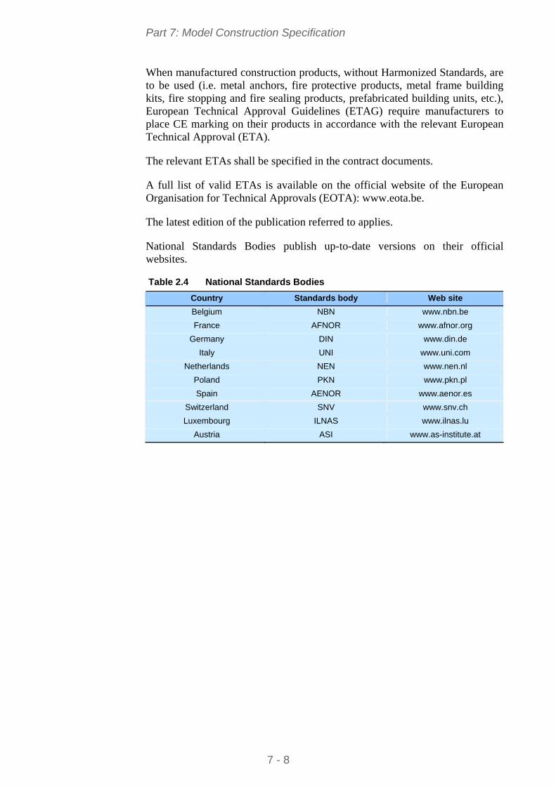
Part 7: Model Construction Specification
When manufactured construction products, without Harmonized Standards, are to be used (i.e. metal anchors, fire protective products, metal frame building kits, fire stopping and fire sealing products, prefabricated building units, etc.), European Technical Approval Guidelines (ETAG) require manufacturers to place CE marking on their products in accordance with the relevant European Technical Approval (ETA).
The relevant ETAs shall be specified in the contract documents.
A full list of valid ETAs is available on the official website of the European Organisation for Technical Approvals (EOTA): www.eota.be.
The latest edition of the publication referred to applies.
National Standards Bodies publish up-to-date versions on their official websites.
Table 2.4 National Standards Bodies
Country Standards body Web site
Belgium NBN www.nbn.be
France AFNOR www.afnor.org
Germany DIN www.din.de
Italy UNI www.uni.com
Netherlands NEN www.nen.nl
Poland PKN www.pkn.pl
Spain AENOR www.aenor.es
Switzerland SNV www.snv.ch
Luxembourg ILNAS www.ilnas.lu
Austria ASI www.as-institute.at
7 - 8
Part 7: Model Construction Specification
3 BASIS OF STRUCTURAL DESIGN
EN 1990 establishes the Principles and Requirements for safety, serviceability and durability of structures, describes the basis for their design and verification and gives guidelines for related aspects of structural reliability.
For the design of new structures, EN 1990 is intended to be used, for direct application, together with Eurocodes EN 1991 to 1999.
EN 1990 is applicable for the structural appraisal of existing construction, in developing the design of repairs and alterations or in assessing changes of use.
Design of steel structures shall conform to the basic requirements of § 2.1 of EN 1990.
Reliability, durability and quality management shall conform to § 2.2, § 2.4 and § 2.5 of EN 1990.
National choice is allowed through clauses listed in the Foreword to EN 1990.
3.1 General assumptions according to EN 1990 The choice of structural system and the design of the structure is made by
appropriately qualified and experienced personnel
Execution is carried out by personnel having the appropriate skill and experience
Adequate supervision and quality control is provided during the execution of the work, i.e. in design offices, factories, plants and on site
The construction materials and products are used as specified in EN 1990 or in the relevant execution standards or reference material or product specifications
The structure will be adequately maintained
The structure will be used in accordance with the design assumptions.
Additional contract document requirements
According to § 2.1(4)P of EN 1990, relevant additional specific events (impact, explosion, etc.), defined by the Client and the relevant authority, must be taken into account in the design and the execution of a structure.
According to § 2.3 of EN 1990, the contract documents should specify the design working life of the structure.
According to § 3.3(2) of EN 1990, the contract documents should state any relevant additional specific circumstances where the limit states that concern the protection of the contents are to classified as ultimate limit states.
According to § 3.4(1) of EN 1990, the contract documents shall specify the serviceability requirements of the project.
7 - 9
Part 7: Model Construction Specification
4 ACTIONS ON STRUCTURES
4.1 Self-weight and imposed loads for buildings EN 1991-1-1 gives design guidance and actions for the structural design of buildings, including the following aspects:
Densities of construction materials and stored materials
Self-weight of construction elements
Imposed loads for buildings.
National choice is allowed through clauses listed in the Foreword to EN 1991-1-1.
Additional contract document requirements
According to § 3.3.2(4) of EN 1991-1-1, the contract documents shall specify the imposed loads to be considered for serviceability limit state verifications, in accordance with the service conditions and the requirements concerning the performance of the structure.
According to Clauses 4.1(1) and 4.1(2) of EN 1991-1-1, characteristic values of densities of construction and stored materials shall be specified in the contract documents, especially for materials which are not covered by the Tables in Appendix A.
According to § 6.1(4) of EN 1991-1-1, loads for heavy equipment (e.g. in communal kitchens, radiology rooms, boiler rooms, etc.) shall be agreed between the Client and the relevant authority and specified in the contract documents.
4.2 Snow loads EN 1991-1-3 gives guidance to determine the values of loads due to snow, to be used for the structural design of buildings.
National choice is allowed through clauses listed in the Foreword to EN 1991-1-3.
Additional contract document requirements
According to § 1.5 of EN 1991-1-3, in some circumstances tests and proven and/or properly validated numerical methods may be used to obtain snow loads on the construction works. These circumstances are those agreed with the Client and the relevant authority, and specified in the contract documents.
According to § 4.1(1) of EN 1991-1-3, to cover unusual local conditions, the National Annex may additionally allow the Client and the relevant authority to agree upon different characteristic values of snow load which have to be specified in the contract documents.
7 - 10
Part 7: Model Construction Specification
4.3 Wind loads EN 1991-1-4 gives guidance on the determination of natural wind actions for the structural design of buildings (with heights up to 200 m) for each of the loaded areas under consideration.
National choice is allowed through clauses listed in the Foreword to EN 1991-1-4.
Additional contract document requirements
According to § 7.2.2 of EN 1991-1-4, the rules for the velocity pressure distribution for leeward wall and sidewalls may be given in the National Annex or be defined for the individual project and specified in the contract documents.
4.4 Thermal actions EN 1991-1-5 gives design guidance, principles and rules for calculating thermal actions arising from climatic and operational conditions for the structural design of buildings. Principles needed for cladding and other appendages of buildings are also provided.
EN 1991-1-5 describes the changes in the temperature of structural elements. Characteristic values of thermal actions are presented for use in the design of structures which are exposed to daily and seasonal climatic changes. For structures not exposed to climatic conditions, thermal actions may not need to be considered.
National choice is allowed through clauses listed in the Foreword to EN 1991-1-5.
Additional contract document requirements
According to § 5.2(2)P of EN 1991-1-5, operational effects (due to heating, technological or industrial processes) shall be considered in accordance with the particular project, and thus specified in the contract documents.
According to § 5.2(3)P of EN 1991-1-5, values of TM and Tp may be provided for the particular project, and thus specified in the contract documents.
4.5 Actions during execution EN 1991-1-6 gives principles and general rules for the determination of actions to be taken into account during the execution of buildings. EN 1991-1-6 can be used as guidance for the determination of actions to be taken into account during structural alterations, reconstruction, partial or full demolition, and for the determination of actions to be used for the design of auxiliary construction works (false-work, scaffolding, propping system etc.) needed for the execution phases. Rules and additional information are given in Annexes A1 and B, and can also be defined in the National Annex or in the contract documents for the individual project.
7 - 11
Part 7: Model Construction Specification
National choice is allowed through clauses listed in the Foreword to EN 1991-1-6.
Additional contract document requirements
The rules concerning the safety of persons, on and around the construction site, shall be specified in the contract documents for the individual project, and are outside the scope of EN 1991-1-6.
EN 1991-1-6 also provides rules for determining the actions that can be used for the calculation of auxiliary construction works needed for the execution phases.
The contract documents shall classify construction loads in accordance with Tables 2.2 and 4.1 of EN 1991-1-6.
Loads due to construction equipments, cranes and/or auxiliary structures can be classified as fixed or free loads, depending on their possible spatial variation; contract documents shall specify the loads and their classification.
If construction loads are classified as fixed, then the contract documents shall define tolerances for the possible deviations to the theoretical position.
If construction loads are classified as free, then the contract documents shall define the limits of the potential area of spatial variation.
In the absence of any specific requirement in the National Annex, the contract documents shall specify:
Return periods for the assessment of the characteristic values of variable (climatic, seismic, etc.) actions during execution phases (see § 3.1(5) of EN 1991-1-6)
A minimum wind velocity during execution phases (see § 3.1(5) of EN 1991-1-6)
Rules of combination of snow loads and wind action with the construction loads (see § 3.1(7) of EN 1991-1-6)
Geometric imperfections of the structure and the structural elements, for the selected design situations during execution (see § 3.1(8) of EN 1991-1-6)
Criteria associated with serviceability limit states during execution (see § 3.3(2) of EN 1991-1-6)
When appropriate, frequent values of particular loads to be taken into account (see § 3.3(5) of EN 1991-1-6)
Requirements of suitability for service of auxiliary structures in order to avoid excessive deformation and/or deflection that affect the durability, fitness for use or aesthetic appearance in the final stage (see § 3.3(6) of EN 1991-1-6).
Concerning the wind actions, the contract documents shall specify, whether or not a procedure is needed for calculating dynamic response of the structure, during the various stages of execution, taking into account the degree of
7 - 12
Part 7: Model Construction Specification
completion and stability of the structure and its components (see § 4.7(1) of EN 1991-1-6).
The contract documents shall specify the maximum allowable wind velocity during crane operations or other short term execution stages (see § 4.7(1) of EN 1991-1-6).
The contract documents shall specify, when relevant, accidental design situations due to cranes or exceptional conditions applicable to the structure or its exposure, such as impact, local failure and subsequent progressive collapse, fall of structural or non-structural parts, and abnormal concentrations of building equipment and/or building materials, water accumulation on steel roofs, fire, etc. (see Clauses 4.12(1) and (3) of EN 1991-1-6).
The contract documents shall specify, when relevant, the design values of the ground acceleration as well as the importance factor I to be taken into account for the assessment of seismic actions, given the reference period of the considered transient situation (see § 4.13 of EN 1991-1-6).
The contract documents shall specify the characteristic values of horizontal actions due to imperfections or deformations related to horizontal displacements to be taken into account during execution phases (see § A1.3(1) of EN 1991-1-6).
4.6 Accidental actions EN 1991-1-7 describes Principles and Application rules for the assessment of accidental actions on buildings and bridges. The following actions are included:
Impact forces from vehicles, rail traffic, ships and helicopters
Actions due to internal explosions
Actions due to local failure from an unspecified cause.
EN 1991-1-7 does not specifically deal with accidental actions caused by external explosions, warfare and terrorist activities, or the residual stability of buildings damaged by seismic action or fire.
National choice is allowed through clauses listed in the Foreword to EN 1991-1-7.
Additional contract document requirements
According to § 2(2)P of EN 1991-1-7, the contract documents may specify the treatment of accidental actions which are not classified as free actions.
According to § 3.1(2) of EN 1991-1-7, the contract documents shall specify the strategies and rules to be considered for accidental design situations.
According to § 3.1(2) of EN 1991-1-7, notional values for identified accidental actions may be specified in the contract documents.
7 - 13
Part 7: Model Construction Specification
According to § 3.4(1) of EN 1991-1-7, the strategies for accidental design situations may be based on the Consequence Classes as set out in EN 1990. Thus, these Consequence Classes shall be specified in the contract documents.
According to § 4.3.1(2) of EN 1991-1-7, the contract documents shall specify whether or not the equivalent static design forces due to vehicular impact on members supporting structures over or adjacent to roadways, Fdx and Fdy, act simultaneously.
According to § 4.5.1.2 of EN 1991-1-7, if the building may be subject to impact from derailed railway traffic, the contract documents shall define whether it is a Class A or Class B structure.
According to § 4.5.1.2(1) of EN 1991-1-7, frontal and lateral dynamic design forces due to impact from river and canal traffic, as well as the height of application of the impact force and the impact area shall be specified in the contract documents.
4.7 Seismic actions EN 1998-1 applies to the design and construction of buildings and civil engineering works in seismic regions. Its purpose is to ensure that in the event of earthquakes:
Human lives are protected
Damage is limited
Structures important for civil protection remain operational (special structures such as nuclear power plants, offshore structures and large dams, are beyond the scope of EN 1998-1).
One fundamental issue in EN 1998-1 is the definition of the seismic action. Given the wide difference of seismic hazard and seismo-genetic characteristics in the various member countries, the seismic action is herein defined in general terms. The definition allows various Nationally Determined Parameters which shall be confirmed or modified in the National Annexes.
National choice is allowed through clauses listed in the Foreword to EN 1998-1.
Additional contract document requirements
According to § 2.1(2) and (3) of EN 1998-1, target reliabilities for the no-collapse requirement and for the damage limitation requirement are established by the National Authorities for different types of buildings on the basis of the consequences of failure. Contract documents shall specify the Importance Class of the individual project (see 4.2.5 of EN 1998-1).
Depending on the Importance Class of the structure and the particular conditions of the project, contract documents shall specify whether or not ground investigations and/or geological studies shall be performed to identify the ground type (A, B, C, D, E, S1 or S2), according to Table 3.1 of EN 1998-1.
7 - 14
Part 7: Model Construction Specification
Contract documents shall specify the seismic zone of the individual project (according to the zonation map, decided by the National Authority, and found in the National Annex to EN 1998-1).
Contract documents shall specify according to which concept earthquake resistant steel buildings shall be designed to (DCL, DCM or DCH).
According to 6.2(8) of EN 1998-1, the required toughness of steel and welds and the lowest service temperature adopted in combination with the seismic action shall be defined in the contract documents.
7 - 15
Part 7: Model Construction Specification
5 DESIGN OF STEEL STRUCTURES
Eurocode 3 is intended to be used in conjunction with:
EN 1990 Basis of structural design
EN 1991 Actions on structures
ENs, ETAGs and ETAs for construction products relevant for steel structures
EN 1090 Execution of Steel Structures – Technical requirements
EN 1992 to EN 1999 when steel structures or steel components are referred to.
Eurocode 3 is concerned only with requirements for resistance, serviceability, durability and fire resistance of steel structures. Other requirements, e.g. concerning thermal or sound insulation, are not covered.
5.1 Rules for multi-storey buildings – EN 1993-1-1 EN 1993-1-1 gives basic design rules for steel structures with material thicknesses t > 3 mm. It also gives supplementary provisions for the structural design of multi-storey steel buildings.
Material properties for steels and other construction products and the geometrical data to be used for design shall be those specified in the relevant ENs, ETAGs or ETAs unless otherwise indicated.
National choice is allowed through clauses listed in the Foreword to EN 1993-1-1.
Additional contract document requirements
The design working life shall be taken as the period for which a building structure is expected to be used for its intended purpose. For the specification of the intended design working life of a permanent building see Table 2.1 of EN 1990.
The effects of deterioration of material, corrosion or fatigue where relevant shall be taken into account by appropriate choice of material, see EN 1993-1-4 and EN 1993-1-10, and details, see EN 1993-1-9, or by structural redundancy and by the choice of an appropriate corrosion protection system.
The dimensional and mass tolerances of rolled steel sections and plates shall comply with the relevant product standard, ETAG or ETA unless more severe tolerances are specified.
Any semi-finished or finished structural product used in the structural design of buildings shall comply with the relevant EN Product Standard or ETAG or ETA.
7 - 16
Part 7: Model Construction Specification
With reference to Annex A1.4 of EN 1990, limits for vertical deflections according to Figure A1.1, for horizontal deflections according to Figure A1.2 and for vibrations of structures on which the public can walk, shall be specified in the contract documents and agreed with the Client.
5.2 Design of joints – EN 1993-1-8 EN 1993-1-8 gives design methods for the design of joints subject to predominantly static loading using steel grades S235, S275, S355 and S460.
National choice is allowed through clauses listed in the Foreword to EN 1993-1-8.
Additional contract document requirements
According to § 3.4.1 of EN 1993-1-8, the Category of bolted connections (Category A, B or C for joints loaded in shear, and Category D or E for joints loaded in tension) shall be specified in the contract documents.
According to § 3.9 of EN 1993-1-8, the contract documents shall specify the class of friction surfaces for slip-resistant connections using pre-loaded 8.8 or 10.9 bolts.
According to § 4.1 of EN 1993-1-8, the contract documents shall specify the quality level of welds according to EN ISO 25817. The frequency of inspection of welds shall be specified in the contract documents and shall conform to the requirements of EN 1090-2.
5.3 Material toughness and through-thickness properties – EN 1993-1-10 EN 1993-1-10 contains design guidance for the selection of steel for fracture toughness and for through-thickness properties of welded elements where there is a significant risk of lamellar tearing during fabrication, for constructions executed in accordance with EN 1090-2.
The guidance given in Section 2 of EN 1993-1-10 shall be used for the selection of material for new construction. The rules shall be used to select a suitable steel grade from the European Standards for steel products listed in EN 1993-1-1.
The choice of Quality Class shall be selected from Table 3.1 EN 1993-1-10 depending on the consequences of lamellar tearing.
Depending on the Quality Class selected from Table 3.1, either:
through thickness properties for the steel material shall be specified from EN 10164, or
post-fabrication inspection shall be used to identify whether lamellar tearing has occurred.
7 - 17
Part 7: Model Construction Specification
Guidance on the avoidance of lamellar tearing during welding is given in EN 1011-2.
National choice is allowed through clauses listed in the Foreword to EN 1993-1-10
5.4 Composite steel and concrete structures – EN 1994-1-1 EN 1994-1-1 describes the Principles and requirements for safety, serviceability and durability of composite steel and concrete structures, together with specific provisions for multi-storey buildings.
National choice is allowed through clauses listed in the Foreword to EN 1994-1-1.
Additional contract document requirements
According to § 4.2 of EN 1994-1-1, the exposed surfaces of profiled steel sheeting for composite slabs in multi-storey buildings shall be adequately protected to resist the particular atmospheric conditions. A zinc coating of total mass 275 g/m² (both sides) is sufficient for internal floors in a non-aggressive environment, unless otherwise specified in the contract documents, depending on service conditions.
According to § 7.3.1(8) of EN 1994-1-1:2004, the effect of curvature due to shrinkage of normal weight concrete need not be included when the ratio of span to overall depth of the beam is not greater than 20, unless specifically required by the contract documents.
7 - 18
Part 7: Model Construction Specification
6 EXECUTION SPECIFICATION
6.1 General The necessary information and technical requirements for execution of each part of the works shall be agreed and complete before commencement of execution of that part of the works. Execution of works shall comply with the requirements of EN 1090-2.
6.2 Execution classes Execution Classes (EXC1 to EXC4) may apply to the whole structure or to a part of the structure or to specific details. A structure can include several Execution Classes. A detail or group of details will normally be ascribed one Execution Class. However, the choice of an Execution Class does not necessarily have to be the same for all requirements.
If no Execution Class is specified EXC2 shall apply.
The list of requirements related to Execution Classes is given in Annex A.3 of EN 1090-2.
Guidance for the choice of Execution Classes is given in Annex B of EN 1090-2.
The choice of Execution Classes is related to Production Categories and Service Categories, with links to Consequence Classes as defined in Annex B of EN 1990.
6.3 Preparation grades Preparation grades (P1 to P3 according to ISO 8501-3) are related to the expected life of the corrosion protection and corrosivity category as defined in § 10 of EN 1090-2.
Preparation grades may apply to the whole structure or to a part of the structure or to specific details. A structure can include several preparation grades. A detail or group of details will normally be ascribed one preparation grade.
6.4 Geometrical tolerances Two types of geometrical tolerances are defined in § 11 of EN 1090-2:
a) Essential tolerances shall be in accordance with Annex D.1 of EN 1090-2. The values specified are permitted deviations.
- Manufacturing tolerances are described in § 11.2.2 of EN 1090-2
- Erection tolerances are described in § 11.2.3 of EN 1090-2.
7 - 19
Part 7: Model Construction Specification
b) Functional tolerances in terms of accepted geometrical deviations shall be in accordance with one of the following two options:
- The tabulated values described in § 11.3.2 and Annex D.2 of EN 1090-2
- The alternative criteria defined in § 11.3.3 of EN 1090-2.
If no option is specified the tabulated values shall apply.
Tolerances on products are defined in the standards:
- EN 10034 for structural steel I and H sections,
- EN 10056-2 for angles,
- EN 10210-2 for hot-finished structural hollow sections,
- EN 10219-2 for cold formed hollow sections.
7 - 20
Part 7: Model Construction Specification
7 CONSTITUENT PRODUCTS
7.1 Identification, inspection documents and traceability If constituent products that are not covered by the European Standards listed in Table 2 of EN 1090-2, are to be used, their properties shall be specified in the contract documents.
The properties of supplied constituent products shall be documented in a way that enables them to be compared to the specified properties. Their conformity with the relevant product standard shall be checked in accordance with § 12.2 of EN 1090-2.
For metallic products, the inspection documents according to EN 10204 shall be as listed in Table 1 of EN 1090-2.
For Execution Classes EXC3 and EXC4, constituent products shall be traceable at all stages from receipt to hand over after incorporation in the works.
For Execution Classes EXC2, EXC3 and EXC4, if differing grades and/or qualities of constituent products are in circulation together, each item shall be designated with a mark that identifies its grade.
Methods of marking shall be in accordance with that for components given in § 6.2 of EN 1090-2.
7.2 Structural steel products Structural steel products shall conform to the requirements of the relevant European product standards as listed in Table 2 of EN 1090-2, unless otherwise specified. Grades, qualities and, if appropriate, coating weights and finishes, shall be specified together with any required options permitted by the product standard, including those related to suitability for hot dip zinc-coating, if relevant.
7.3 Welding consumables All welding consumables shall conform to the requirements of EN 13479 and the appropriate product standard, as listed in Table 5 of EN 1090-2. The type of welding consumables shall be appropriate to the welding process (defined in § 7.3 of EN 1090-2), the material to be welded and the welding procedure.
7.4 Mechanical fasteners All mechanical fasteners (connectors, bolts, fasteners) shall conform to the requirements of § 5.6 of EN 1090-2.
7.5 Grouting materials The grouting materials to be used shall conform to the requirements of § 5.7 of EN 1090-2.
7 - 21
Part 7: Model Construction Specification
8 PREPARATION AND ASSEMBLY
This Section specifies the requirements for cutting, shaping, holing and assembly of constituent steel components.
Structural steelwork shall be fabricated considering the surface treatment requirements in § 10 of EN 1090-2, and within the geometrical tolerances specified in § 11 of EN 1090-2.
8.1 Identification At all stages of manufacturing, each piece or package of similar pieces of steel components shall be identifiable by a suitable system, according to the requirements of § 6.2 of EN 1090-2.
8.2 Handling and storage Constituent products shall be handled and stored in conditions that are in accordance with product manufacturer's recommendations. Structural steel components shall be packed, handled and transported in a safe manner, so that permanent deformation does not occur and surface damage is minimized.
Handling and storage preventive measures specified in Table 8 of EN 1090-2 shall be applied as appropriate.
8.3 Cutting Known and recognized cutting methods are sawing, shearing, disc cutting, water jet techniques and thermal cutting. Hand thermal cutting shall be used only if it is not practical to use machine thermal cutting. Cutting shall be carried out in such a way that the requirements for geometrical tolerances, maximum hardness and smoothness of free edges as specified in § 6.4 of EN 1090-2 are met.
8.4 Shaping Steel may be bent, pressed or forged to the required shape either by the hot or by the cold forming processes, provided the properties are not reduced below those specified for the worked material.
Requirements of § 6.5 of EN 1090-2 shall be applied as appropriate.
8.5 Holing Dimensions of holes, tolerances on hole-diameters and execution of holing shall comply with the requirements of § 6.6 of EN 1090-2.
8.6 Assembly Assembly of components shall be carried out so as to fulfil the specified tolerances. Precautions shall be taken so as to prevent galvanic corrosion produced by contact between different metallic materials.
Requirements of § 6.9 and § 6.10 of EN 1090-2 shall be applied as appropriate.
7 - 22
Part 7: Model Construction Specification
9 WELDING
9.1 General Welding shall be undertaken in accordance with the requirements of the relevant part of EN ISO 3834 or EN ISO 14554 as applicable.
A welding plan shall be provided as part of the production planning required by the relevant part of EN ISO 3834. The content of a welding plan is described in § 7.2.2 of EN 1090-2.
Welding may be performed by the welding processes defined in EN ISO 4063, that are listed in § 7.3 of EN 1090-2.
9.2 Qualification of welding procedures Welding shall be carried out with qualified procedures using a Welding Procedure Specification (WPS) in accordance with the relevant part of EN ISO 15609 or EN ISO 14555 or EN ISO 15620. If specified, special deposition conditions for tack welds shall be included in the WPS.
Qualifications of welding procedures, depending on welding processes, are described in § 7.4.1.2 and § 7.4.1.3 of EN 1090-2.
9.3 Welders and welding operators Welders shall be qualified in accordance with EN 287-1 and welding operators in accordance with EN 1418. Records of all welder and welding operator qualification tests shall be kept available.
9.4 Welding coordination For Execution Class EXC2, EXC3 and EXC4, welding coordination shall be maintained during the execution of welding by welding coordination personnel suitably qualified for, and experienced in the welding operations they supervise as specified in EN ISO 14731.
With respect to the welding operations being supervised, and for structural carbon steels, welding coordination personnel shall have a technical knowledge according to Table 14 of EN 1090-2.
9.5 Preparation and execution of welding Precautions shall be taken to avoid stray arcing, and if stray arcing does occur the surface of the steel shall be lightly ground and checked. Visual checking shall be supplemented by penetrant or magnetic particle testing.
Precautions shall be taken to avoid weld spatter. For Execution Class EXC3 and EXC4, it shall be removed.
7 - 23
Part 7: Model Construction Specification
Visible imperfections such as cracks, cavities and other not permitted imperfections shall be removed from each run before deposition of further runs.
All slag shall be removed from the surface of each run before each subsequent run is added and from the surface of the finished weld.
Particular attention shall be paid to the junctions between the weld and the parent metal.
Any requirements for grinding and dressing of the surface of completed welds shall be specified.
Joint preparation shall be appropriate for the welding process. If qualification of welding procedures is performed in accordance with EN ISO 15614-1, EN ISO 15612 or EN ISO 15613, joint preparation shall comply with the type of preparation used in the welding procedure test. Tolerances for joints preparations, and fit-up shall be given in the WPSs.
Joint preparation shall be free from visible cracks. Visible cracks shall be removed by grinding and the joint geometry corrected as necessary.
If large notches or other errors in joint geometry are corrected by welding, a qualified procedure shall be used, and the area shall be subsequently ground smooth and feathered into the adjacent surface.
All surfaces to be welded shall be dry and free from material that would adversely affect the quality of the welds or impede the process of welding (rust, organic material or galvanizing).
Prefabrication primers (shop primers) may be left on the fusion faces only if they do not adversely affect the welding process. For Execution Class EXC3 and EXC4, prefabrication primers shall not be left on the fusion faces, unless welding procedure tests in accordance with EN ISO 15614-1 or EN ISO 15613 have been completed using such prefabrication primers.
Other special requirements are described in EN 1090-2, as indicated in Table 9.1.
7 - 24
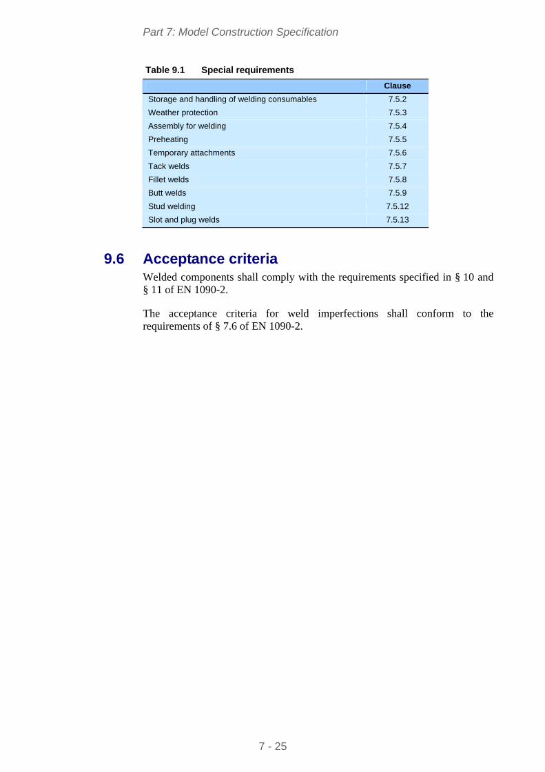
Part 7: Model Construction Specification
Table 9.1 Special requirements
Clause
Storage and handling of welding consumables 7.5.2
Weather protection 7.5.3
Assembly for welding 7.5.4
Preheating 7.5.5
Temporary attachments 7.5.6
Tack welds 7.5.7
Fillet welds 7.5.8
Butt welds 7.5.9
Stud welding 7.5.12
Slot and plug welds 7.5.13
9.6 Acceptance criteria Welded components shall comply with the requirements specified in § 10 and § 11 of EN 1090-2.
The acceptance criteria for weld imperfections shall conform to the requirements of § 7.6 of EN 1090-2.
7 - 25
Part 7: Model Construction Specification
10 MECHANICAL FASTENING
Section 8 of EN 1090-2 covers requirements for shop and site fastening, including the fixing of profiled sheeting; it refers to bolting assemblies consisting of matching bolts, nuts and washers (as necessary).
Contract documents shall specify if, in addition to tightening, other measures or means are to be used to secure the nuts.
Minimum nominal fastener diameter, bolt length, length of protrusion, length of the unthreaded bolt shaft and clamp length shall comply with the requirements of § 8.2.2 of EN 1090-2.
Requirements given in § 8.2.3 of EN 1090-2 for washers shall apply.
Tightening of non-preloaded bolts shall comply with the requirements of § 8.3 of EN 1090-2.
Precautions and preparation of contact surfaces in slip resistant connections shall comply with the requirements of § 8.4 and Table 18 of EN 1090-2. Slip factor shall be determined by test as specified in Annex G of EN 1090-2.
Tightening methods of preloaded bolts shall comply with the requirements of § 8.5 of EN 1090-2, and shall be specified in the contract documents.
7 - 26
Part 7: Model Construction Specification
11 ERECTION
Section 9 of EN 1090-2 gives requirements for erection and other works undertaken on site including grouting of bases as well as those relevant to the suitability of the site for safe erection and for accurately prepared supports.
Erection shall not commence until the site for the construction works complies with the technical requirements with respect to the safety of the works. Safety items related to site conditions are listed in § 9.2 of EN 1090-2.
If the structural stability in the part-erected condition is not evident, a safe method of erection, on which the design was based, shall be provided. Items related to the design basis method of erection are listed in § 9.3.1 of EN 1090-2.
A method statement describing the steelwork contractor's erection method shall be prepared and checked in accordance with design rules. The erection method statement shall describe procedures to be used to safely erect the steelwork and shall take into account the technical requirements regarding the safety of the works. The erection method statement shall address all relevant items in § 9.3.1 of EN 1090-2; additional items are listed in § 9.3.2 of EN 1090-2.
Erection drawings or equivalent instructions, in accordance with the requirements of § 9.6.1 of EN 1090-2, shall be provided and form part of the erection method statement.
Site measurements for the works shall be in accordance with the survey requirements of § 9.4 of EN 1090-2.
The condition and location of the supports shall be checked visually and by appropriate measurement before the commencement of erection. If supports are unsuited to erection, they shall be corrected prior to the commencement of erection. Nonconformities shall be documented.
All foundations, foundation bolts and other supports for the steelwork shall be suitably prepared to receive the steel structure. Installation of structural bearings shall comply with the requirements of EN 1337-11. Erection shall not commence until the location and levels of the supports, anchors or bearings comply with the acceptance criteria in § 11.2 of EN 1090-2, or an appropriate amendment to the specified requirements.
If foundation bolts are to be pre-stressed, arrangements shall be made that the upper 100 mm of the bolt, as a minimum, has no adhesion to the concrete. Foundation bolts intended to move in sleeves shall be provided with sleeves three times the diameter of the bolt, with a minimum of 75 mm.
Whilst erection is proceeding, the supports for the steelwork shall be maintained in an equivalent condition to their condition at the commencement of erection.
7 - 27
Part 7: Model Construction Specification
Areas of supports that require protection against rust staining shall be identified and appropriate protection provided.
Compensation for settlement of supports is acceptable, unless otherwise specified in the contract documents. This shall be done by grouting or packing between steelwork and support. The compensation will generally be placed beneath the bearing.
Shims and other supporting devices used as temporary supports under base plates shall be placed in accordance with the requirements of § 8.3, 8.5.1, 9.5.4 and 9.6.5.3 of EN 1090-2.
Grouting, sealing and anchoring shall be set in accordance with their specification and the requirements of § 5.8, 9.5.5 and 9.5.6 of EN 1090-2.
Components that are individually assembled or erected at the site shall be allocated an erection mark, in accordance with the requirements of § 6.2 and 9.6.2 of EN 1090-2.
Handling and storage on site shall comply with the requirements of § 6.3 and 9.6.3 of EN 1090-2.
Any site trial erection shall be performed in accordance with the requirements of Clauses 6.10 and 9.6.10 of EN 1090-2.
The erection of the steelwork shall be carried out in conformity with the erection method statement and in such a way as to ensure stability at all times.
Foundation bolts shall not be used to secure unguyed columns against overturning unless they have been checked for this design situation.
Throughout the erection of the structure, the steelwork shall be made safe against temporary erection loads, including those due to erection equipment or its operation and against the effects of wind loads on the unfinished structure.
At least one third of the permanent bolts in each connection should be installed before that connection can be considered to contribute to stability of the part completed structure.
All temporary bracing and temporary restraints shall be left in position until erection is sufficiently advanced to allow its safe removal.
All connections for temporary components provided for erection purposes shall be made in accordance with the requirements of EN 1090-2 and in such a way that they do not weaken the permanent structure or impair its serviceability.
If backing bars and draw cleats are used to support the structure during welding, it shall be ensured that they are sufficiently strong and that their retaining welds are appropriate for the erection load conditions.
If the erection procedure involves rolling or otherwise moving the structure, or part of the structure, into its final position after assembly, provision shall be
7 - 28
Part 7: Model Construction Specification
made for controlled braking of the moving mass. Provision for reversing the direction of movement may need to be considered.
All temporary anchoring devices shall be made secure against unintentional release.
Only jacks that can be locked in any position under load shall be used unless other safety provisions are made.
Care shall be taken that no part of the structure is permanently distorted or over-stressed by stacking of steelwork components or by erection loads during the erection process.
Each part of the structure shall be aligned as soon as practicable after it has been erected and final assembly completed as soon as possible thereafter.
Permanent connections shall not be made between components until sufficient of the structure has been aligned, levelled, plumbed and temporarily connected to ensure that components will not be displaced during subsequent erection or alignment of the remainder of the structure.
Alignment of the structure and lack-of-fit in connections may be adjusted by the use of shims (see above). If lack-of-fit between erected components cannot be corrected by the use of shims, components of the structure shall be locally modified in accordance with the methods specified in EN 1090-2. The modifications shall not compromise the performance of the structure in the temporary or permanent state. This work may be executed on site. Care shall be taken with structures built of welded latticed components and space structures to ensure that they are not subjected to excessive forces in an attempt to force a fit against their inherent rigidity.
Unless otherwise prohibited in the contract documents, drifts may be used to align connections. Elongation of holes for bolts used for transmission of loads shall not be more than the values given in § 6.9 of EN 1090-2.
In case of misalignment of holes for bolts, the method of correction shall be checked for consistency with the requirements of § 12 of EN 1090-2.
Realigned holes may be proven to comply with the oversize or slotted hole requirements specified in 8.1 of EN 1090-2, provided the load path has been checked.
Correction of misalignment by reaming or using a hollow milling cutter is preferred, but if the use of other cutting methods is unavoidable the internal finish of all holes formed by these other methods shall be specifically checked for consistency with the requirements of § 6 of EN 1090-2.
Completed site connections shall be checked in accordance with 12.5 of EN 1090-2.
Erection tolerances are detailed in § 11.2.3 and Tables D.1.11 to D.1.15 and Tables D.2.19 to D.2.28 of Annex D of EN 1090-2.
7 - 29
Part 7: Model Construction Specification
12 CONSTRUCTOR’S DOCUMENTATION
Quality documentation, mandatory for Execution Classes EXC2 to EXC4, is defined in § 4.2.1 of EN 1090-2.
If required, a quality plan (defined in EN ISO 9000) for the execution of the works is described in § 4.2.2 of EN 1090-2. Annex C of EN 1090-2 gives a check-list for the content of a quality plan recommended for the execution of structural steelwork with reference to the general guidelines in ISO 10005.
Method statements giving detailed work instructions shall comply with the technical requirements relating to the safety of the erection works as given in § 9.2 and § 9.3 of EN 1090-2.
Sufficient documentation shall be prepared during execution and as a record of the as-built structure to demonstrate that the works have been carried out according to the execution specification.
Design and structural engineering documentation shall be prepared before execution of the works, and approved by any approval body designated by the Owner. The documentation should contain:
Design assumptions
Software used (if any)
Member and joint design verification
General Arrangement drawings and joint details.
7 - 30
Part 7: Model Construction Specification
13 INTERFACES OF THE STEEL STRUCTURE
13.1 Interface to concrete surfaces Information showing holding-down bolts and the interface of steelwork components to foundations shall include a Foundation Plan showing the base location, position and orientation of columns, the marks of all columns, any other components in direct contact with the foundations, their base location and level, and the datum level.
Similar information shall also be provided for components connecting to walls and other concrete surfaces.
Complete details of fixing steel and bolts to the foundations or walls, method of adjustment and packing space shall be provided.
Before erection of steelwork starts, the steelwork contractor shall inspect the prepared foundations and holding-down bolts for position and level; if he finds any discrepancies which are outside the deviations specified in § D.2.20 of EN 1090-2, he shall request that remedial work be carried out before erection commences.
Shims and other supporting devices used as temporary supports under base plates shall present a flat surface to the steel and be of adequate size, strength and rigidity to avoid local crushing of the substructure concrete or masonry.
If packings are subsequently to be grouted, they shall be placed so that the grout totally encloses them with a minimum cover of 25 mm unless otherwise specified.
If packings are left in position after grouting, they shall be made from materials with the same durability as the structure.
If adjustment to the position of the base is achieved using levelling nuts on the foundation bolts under the base plate, these may be left in position unless otherwise specified. The nuts shall be selected to ensure that they are suitable to maintain the stability of the part-erected structure but not to jeopardize the performance of the foundation bolt in service.
If spaces under base plates are to be grouted, fresh material shall be used in accordance with § 5.8 of EN 1090-2.
Grouting shall not be carried out under column base plates until a sufficient portion of the structure has been aligned, levelled, plumbed and adequately braced.
Grouting material shall be used as follows:
The material shall be mixed and used in accordance with product manufacturer's recommendations notably regarding its consistency when used. Material shall not be mixed or used below 0°C unless the manufacturer's recommendations permit it.
7 - 31
Part 7: Model Construction Specification
The material shall be poured under a suitable head so that the space is completely filled.
Tamping and ramming against properly fixed supports shall be used if specified and/or recommended by the grout manufacturer.
Vent holes shall be provided as necessary.
Immediately before grouting, the space under the steel base plate shall be free from liquids, ice, debris and contaminants.
If treatment of steelwork, bearings and concrete surfaces is required before grouting, it shall be specified in the contract documents.
Care shall be taken that the external profile of grouting allows water to be drained away from structural steel components. If there is a danger of water or corrosive liquid becoming entrapped during service, the grout around base plates shall not be surcharged such that it rises above the lowest surface of the base plate and the geometry of the concrete grout shall form an angle from the base plate.
If no grouting is needed, and the edges of the base plate are to be sealed, the method shall be specified.
Anchoring devices in concrete parts of the structure or adjacent structures shall be set in accordance with their specification. Suitable measures shall be taken to avoid damage to concrete in order to achieve the necessary anchoring resistance.
Foundations shall be adequately designed by a qualified foundation engineer to support the building reactions and other loads which may be imposed by the building use. The design shall be based on the specific soil conditions of the building site.
13.2 Interface to neighbouring constructions The mutual influence of neighbouring constructions for wind or snow actions must be carefully considered. Design wind and snow loads may vary considerably regarding the site and the construction environment, hence, precise indications shall be given, in the contract documents, concerning the surrounding constructions.
7 - 32
Part 7: Model Construction Specification
APPENDIX A MODEL PROJECT SPECIFICATION
The execution of steelwork for multi-storey buildings in Europe will generally be specified to be in accordance with EN 1090-2, and the design to be in accordance with applicable parts of the Eurocode Standards. These Standards, which cover technical requirements for a wide range of steel structures, include clauses where the execution/design specification for the works is required to give additional information or where it has the option to specify other requirements.
Appendix A offers a set of clauses that may be used for multi-storey steel building projects to supplement and quantify the rules of the Europeans Standards.
The clauses are arranged in a two-column format. The left column contains the proposed clauses. The right column gives a commentary to several clauses, for the information of the person drawing up project documents; those commentaries are not intended to be included within the execution specification. The model specification must be made specific to the construction project by completing the relevant clauses with appropriate information.
The model project specification proposed in this Appendix covers structural steelwork produced from hot rolled structural steel products only. It does not cover structural steelwork produced from cold formed structural steel (only cold formed profiled steel sheeting and cold formed stressed-skin sheeting used as a structural diaphragm are herein covered), structural hollow sections, channels and tubes and stainless steel products. This model project specification relates principally to conventional construction using constituent products to the standards referenced in EN 1090-2. If more complex forms of construction are involved or other products are used, designers need to consider any modifications that might be needed to the execution specification to ensure that the desired quality and/or functionality are achieved.
For consistency, in Appendix A, those clause headings that are numbered and in bold, correspond to the Section headings of this document.
7 - 33
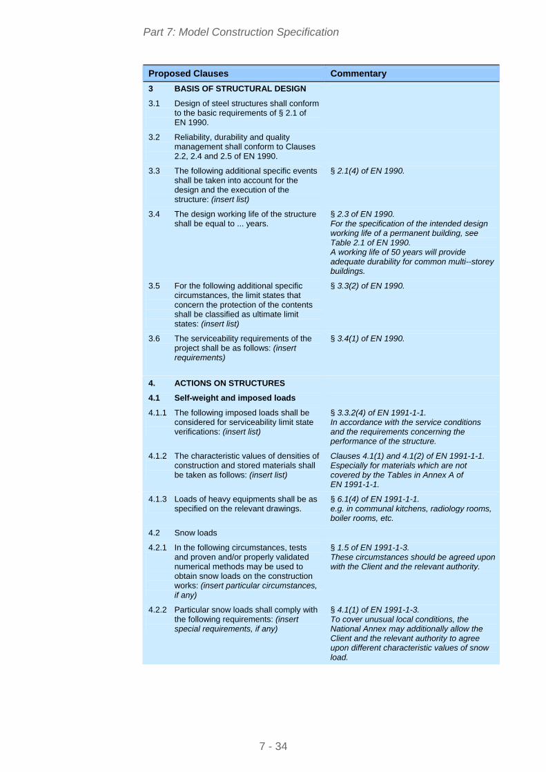
Part 7: Model Construction Specification
Proposed Clauses Commentary
3 BASIS OF STRUCTURAL DESIGN
3.1 Design of steel structures shall conform to the basic requirements of § 2.1 of EN 1990.
3.2 Reliability, durability and quality management shall conform to Clauses 2.2, 2.4 and 2.5 of EN 1990.
3.3 The following additional specific events shall be taken into account for the design and the execution of the structure: (insert list)
§ 2.1(4) of EN 1990.
3.4 The design working life of the structure shall be equal to ... years.
§ 2.3 of EN 1990. For the specification of the intended design working life of a permanent building, see Table 2.1 of EN 1990. A working life of 50 years will provide adequate durability for common multi--storey buildings.
3.5 For the following additional specific circumstances, the limit states that concern the protection of the contents shall be classified as ultimate limit states: (insert list)
§ 3.3(2) of EN 1990.
3.6 The serviceability requirements of the project shall be as follows: (insert requirements)
§ 3.4(1) of EN 1990.
4. ACTIONS ON STRUCTURES
4.1 Self-weight and imposed loads
4.1.1 The following imposed loads shall be considered for serviceability limit state verifications: (insert list)
§ 3.3.2(4) of EN 1991-1-1. In accordance with the service conditions and the requirements concerning the performance of the structure.
4.1.2 The characteristic values of densities of construction and stored materials shall be taken as follows: (insert list)
Clauses 4.1(1) and 4.1(2) of EN 1991-1-1. Especially for materials which are not covered by the Tables in Annex A of EN 1991-1-1.
4.1.3 Loads of heavy equipments shall be as specified on the relevant drawings.
§ 6.1(4) of EN 1991-1-1. e.g. in communal kitchens, radiology rooms, boiler rooms, etc.
4.2 Snow loads
4.2.1 In the following circumstances, tests and proven and/or properly validated numerical methods may be used to obtain snow loads on the construction works: (insert particular circumstances, if any)
§ 1.5 of EN 1991-1-3. These circumstances should be agreed upon with the Client and the relevant authority.
4.2.2 Particular snow loads shall comply with the following requirements: (insert special requirements, if any)
§ 4.1(1) of EN 1991-1-3. To cover unusual local conditions, the National Annex may additionally allow the Client and the relevant authority to agree upon different characteristic values of snow load.
7 - 34
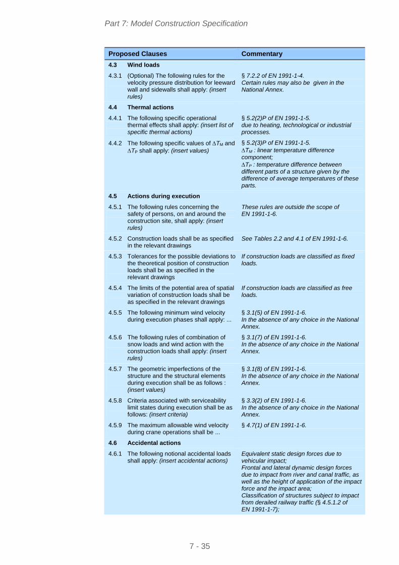
Part 7: Model Construction Specification
Proposed Clauses Commentary
4.3 Wind loads
4.3.1 (Optional) The following rules for the velocity pressure distribution for leeward wall and sidewalls shall apply: (insert rules)
§ 7.2.2 of EN 1991-1-4. Certain rules may also be given in the National Annex.
4.4 Thermal actions
4.4.1 The following specific operational thermal effects shall apply: (insert list of specific thermal actions)
§ 5.2(2)P of EN 1991-1-5. due to heating, technological or industrial processes.
4.4.2 The following specific values of TM and TP shall apply: (insert values)
§ 5.2(3)P of EN 1991-1-5. TM : linear temperature difference component; TP : temperature difference between different parts of a structure given by the difference of average temperatures of these parts.
4.5 Actions during execution
4.5.1 The following rules concerning the safety of persons, on and around the construction site, shall apply: (insert rules)
These rules are outside the scope of EN 1991-1-6.
4.5.2 Construction loads shall be as specified in the relevant drawings
See Tables 2.2 and 4.1 of EN 1991-1-6.
4.5.3 Tolerances for the possible deviations to the theoretical position of construction loads shall be as specified in the relevant drawings
If construction loads are classified as fixed loads.
4.5.4 The limits of the potential area of spatial variation of construction loads shall be as specified in the relevant drawings
If construction loads are classified as free loads.
4.5.5 The following minimum wind velocity during execution phases shall apply: ...
§ 3.1(5) of EN 1991-1-6. In the absence of any choice in the National Annex.
4.5.6 The following rules of combination of snow loads and wind action with the construction loads shall apply: (insert rules)
§ 3.1(7) of EN 1991-1-6. In the absence of any choice in the National Annex.
4.5.7 The geometric imperfections of the structure and the structural elements during execution shall be as follows : (insert values)
§ 3.1(8) of EN 1991-1-6. In the absence of any choice in the National Annex.
4.5.8 Criteria associated with serviceability limit states during execution shall be as follows: (insert criteria)
§ 3.3(2) of EN 1991-1-6. In the absence of any choice in the National Annex.
4.5.9 The maximum allowable wind velocity during crane operations shall be ...
§ 4.7(1) of EN 1991-1-6.
4.6 Accidental actions
4.6.1 The following notional accidental loads shall apply: (insert accidental actions)
Equivalent static design forces due to vehicular impact; Frontal and lateral dynamic design forces due to impact from river and canal traffic, as well as the height of application of the impact force and the impact area; Classification of structures subject to impact from derailed railway traffic (§ 4.5.1.2 of EN 1991-1-7);
7 - 35
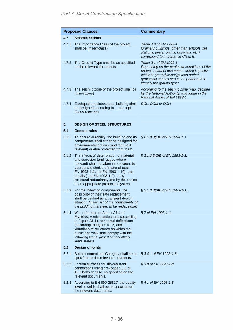
Part 7: Model Construction Specification
Proposed Clauses Commentary
4.7 Seismic actions
4.7.1 The Importance Class of the project shall be (insert class)
Table 4.3 of EN 1998-1. Ordinary buildings (other than schools, fire stations, power plants, hospitals, etc.) correspond to Importance Class II;
4.7.2 The Ground Type shall be as specified on the relevant documents.
Table 3.1 of EN 1998-1. Depending on the particular conditions of the project, contract documents should specify whether ground investigations and/or geological studies should be performed to identify the ground type;
4.7.3 The seismic zone of the project shall be (insert zone)
According to the seismic zone map, decided by the National Authority, and found in the National Annex of EN 1998-1
4.7.4 Earthquake resistant steel building shall be designed according to ... concept (insert concept)
DCL, DCM or DCH.
5. DESIGN OF STEEL STRUCTURES
5.1 General rules
5.1.1 To ensure durability, the building and its components shall either be designed for environmental actions (and fatigue if relevant) or else protected from them.
§ 2.1.3.3(1)B of EN 1993-1-1.
5.1.2 The effects of deterioration of material and corrosion (and fatigue where relevant) shall be taken into account by appropriate choice of material (see EN 1993-1-4 and EN 1993-1-10), and details (see EN 1993-1-9), or by structural redundancy and by the choice of an appropriate protection system.
§ 2.1.3.3(2)B of EN 1993-1-1.
5.1.3 For the following components, the possibility of their safe replacement shall be verified as a transient design situation (insert list of the components of the building that need to be replaceable)
§ 2.1.3.3(3)B of EN 1993-1-1.
5.1.4 With reference to Annex A1.4 of EN 1990, vertical deflections (according to Figure A1.1), horizontal deflections (according to Figure A1.2) and vibrations of structures on which the public can walk shall comply with the following limits: (insert serviceability limits states)
§ 7 of EN 1993-1-1.
5.2 Design of joints
5.2.1 Bolted connections Category shall be as specified on the relevant documents.
§ 3.4.1 of EN 1993-1-8.
5.2.2 Friction surfaces for slip-resistant connections using pre-loaded 8.8 or 10.9 bolts shall be as specified on the relevant documents.
§ 3.9 of EN 1993-1-8.
5.2.3 According to EN ISO 25817, the quality level of welds shall be as specified on the relevant documents.
§ 4.1 of EN 1993-1-8.
7 - 36
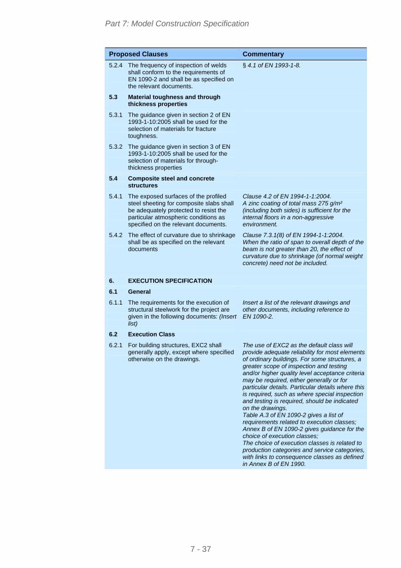
Part 7: Model Construction Specification
Proposed Clauses Commentary
5.2.4 The frequency of inspection of welds shall conform to the requirements of EN 1090-2 and shall be as specified on the relevant documents.
§ 4.1 of EN 1993-1-8.
5.3 Material toughness and through thickness properties
5.3.1 The guidance given in section 2 of EN 1993-1-10:2005 shall be used for the selection of materials for fracture toughness.
5.3.2 The guidance given in section 3 of EN 1993-1-10:2005 shall be used for the selection of materials for through-thickness properties
5.4 Composite steel and concrete structures
5.4.1 The exposed surfaces of the profiled steel sheeting for composite slabs shall be adequately protected to resist the particular atmospheric conditions as specified on the relevant documents.
Clause 4.2 of EN 1994-1-1:2004. A zinc coating of total mass 275 g/m² (including both sides) is sufficient for the internal floors in a non-aggressive environment.
5.4.2 The effect of curvature due to shrinkage shall be as specified on the relevant documents
Clause 7.3.1(8) of EN 1994-1-1:2004. When the ratio of span to overall depth of the beam is not greater than 20, the effect of curvature due to shrinkage (of normal weight concrete) need not be included.
6. EXECUTION SPECIFICATION
6.1 General
6.1.1 The requirements for the execution of structural steelwork for the project are given in the following documents: (Insert list)
Insert a list of the relevant drawings and other documents, including reference to EN 1090-2.
6.2 Execution Class
6.2.1 For building structures, EXC2 shall generally apply, except where specified otherwise on the drawings.
The use of EXC2 as the default class will provide adequate reliability for most elements of ordinary buildings. For some structures, a greater scope of inspection and testing and/or higher quality level acceptance criteria may be required, either generally or for particular details. Particular details where this is required, such as where special inspection and testing is required, should be indicated on the drawings. Table A.3 of EN 1090-2 gives a list of requirements related to execution classes; Annex B of EN 1090-2 gives guidance for the choice of execution classes; The choice of execution classes is related to production categories and service categories, with links to consequence classes as defined in Annex B of EN 1990.
7 - 37
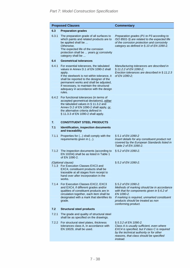
Part 7: Model Construction Specification
Proposed Clauses Commentary
6.3 Preparation grades
6.3.1 The preparation grade of all surfaces to which paints and related products are to be applied shall be ... Otherwise, The expected life of the corrosion protection shall be ... years or corrosivity category shall be ...
Preparation grades (P1 to P3 according to ISO 8501-3) are related to the expected life of the corrosion protection and corrosivity category as defined in § 10 of EN 1090-2.
6.4 Geometrical tolerances
6.4.1 For essential tolerances, the tabulated values in Annex D.1 of EN 1090-2 shall apply. If the steelwork is not within tolerance, it shall be reported to the designer of the permanent works and shall be adjusted, if necessary, to maintain the structural adequacy in accordance with the design rules.
Manufacturing tolerances are described in § 11.2.2 of EN 1090-2; Erection tolerances are described in § 11.2.3 of EN 1090-2;
6.4.2 For functional tolerances (in terms of accepted geometrical deviations), either the tabulated values in § 11.3.2 and Annex D.2 of EN 1090-2 shall apply, or, the alternative criteria defined in § 11.3.3 of EN 1090-2 shall apply.
7. CONSTITUENT STEEL PRODUCTS
7.1 Identification, inspection documents and traceability
7.1.1 Properties for (...) shall comply with the requirements given in (...).
§ 5.1 of EN 1090-2 Insert details for any constituent product not covered by the European Standards listed in Table 2 of EN 1090-2.
7.1.2 The inspection documents (according to EN 10204) shall be as listed in Table 1 of EN 1090-2.
§ 5.2 of EN 1090-2.
(Optional clause) 7.1.3 For Execution Classes EXC3 and
EXC4, constituent products shall be traceable at all stages from receipt to hand over after incorporation in the works.
§ 5.2 of EN 1090-2.
7.1.4 For Execution Classes EXC2, EXC3 and EXC4, if different grades and/or qualities of constituent products are in circulation together, each item shall be designated with a mark that identifies its grade.
§ 5.2 of EN 1090-2. Methods of marking should be in accordance with that for components given in § 6.2 of EN 1090-2. If marking is required, unmarked constituent products should be treated as non conforming product.
7.2 Structural steel products
7.2.1 The grade and quality of structural steel shall be as specified on the drawings.
7.2.2 For structural steel plates, thickness tolerances class A, in accordance with EN 10029, shall be used.
§ 5.3.2 of EN 1090-2. Class A is usually sufficient, even where EXC4 is specified, but if class C is required by the technical authority or for other reasons, that class should be specified instead.
7 - 38
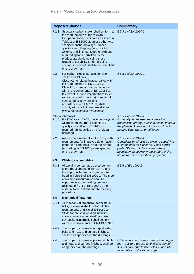
Part 7: Model Construction Specification
Proposed Clauses Commentary
7.2.3 Structural carbon steels shall conform to the requirements of the relevant European product standards as listed in Table 2 of EN 1090-2, unless otherwise specified on the drawings. Grades, qualities and, if appropriate, coating weights and finishes, together with any required options permitted by the product standard, including those related to suitability for hot dip zinc-coating, if relevant, shall be as specified on the drawings.
§ 5.3.1 of EN 1090-2.
7.2.4 For carbon steels, surface condition shall be as follows: Class A2, for plates in accordance with the requirements of EN 10163-2; Class C1, for sections in accordance with the requirements of EN 10163-3. If relevant, surface imperfections (such as cracks, shell or seams) or repair of surface defects by grinding in accordance with EN 10163, shall comply with the following restrictions : (insert list of special restrictions)
§ 5.3.3 of EN 1090-2.
(Optional clause) 7.2.5 For EXC3 and EXC4, the locations (and
width) where internal discontinuity quality class S1 of EN 10160 is required, are specified on the relevant drawings.
§ 5.3.4 of EN 1090-2. Especially for welded cruciform joints transmitting primary tensile stresses through the plate thickness, and for areas close to bearing diaphragms or stiffeners.
7.2.6 Areas where material shall comply with requirements for improved deformation properties perpendicular to the surface (according to EN 10164) are specified on the drawings.
§ 5.3.4 of EN 1090-2. Consideration should be given to specifying such material for cruciform, T and corner joints. Should only be invoked where necessary; specify only those parts of the structure which need these properties.
7.3 Welding consumables
7.3.1 All welding consumables shall conform to the requirements of EN 13479 and the appropriate product standard, as listed in Table 5 of EN 1090-2. The type of welding consumables shall be appropriate to the welding process (defined in § 7.3 of EN 1090-2), the material to be welded and the welding procedure.
§ 5.5 of EN 1090-2.
7.4 Mechanical fasteners
7.4.1 All mechanical fasteners (connectors, bolts, fasteners) shall conform to the requirements of § 5.6 of EN 1090-2. Studs for arc stud welding including shear connectors for steel/concrete composite construction shall comply with the requirements of EN ISO 13918.
7.4.2 The property classes of non-preloaded bolts and nuts, and surface finishes, shall be as specified on the drawings.
7.4.3 The property classes of preloaded bolts and nuts, and surface finishes, shall be as specified on the drawings.
HV bolts are sensitive to over-tightening, so they require a greater level of site control. It is not advisable to use both HR and HV assemblies on the same project.
7 - 39
Part 7: Model Construction Specification
Proposed Clauses Commentary
7.4.4 The chemical composition of weather resistant assemblies shall comply with the requirements for Type 3 Grade A fasteners to ASTM standard A325, or equivalent.
7.4.5 Reinforcing steels may be used for foundation bolts. In this case, they shall conform to EN 10080 and the steel grade shall be as specified on the drawings.
(Optional clause) 7.4.6 Where locking devices are specified on
the drawings, they shall comply with the relevant standards listed in § 5.6.8 of EN 1090-2, and additionally ... (Insert any particular requirements for locking devices).
7.5 Grouting materials
7.5.1 Grouting materials to be used shall be as specified on the relevant drawings.
8. PREPARATION AND ASSEMBLY
8.1 Identification
8.1.1 Soft or low stress stamps may be used, except in any areas specified on the drawings.
Soft or low stress stamp marks can easily be obliterated by the protective system. The fabricator will usually mask the stamped area after application of primer and complete the coating locally after erection.
8.1.2 Areas where identification marks are not permitted or shall not be visible after completion are specified on the drawings.
8.2 Handling and storage
8.2.1 Structural steel components shall be packed, handled and transported in a safe manner, so that permanent deformation does not occur and surface damage is minimized. Handling and storage preventive measures specified in Table 8 of EN 1090-2 shall be applied as appropriate.
8.3 Cutting
8.3.1 Hand thermal cutting shall be used only if it is not practical to use machine thermal cutting. Cutting shall be carried out in such a way that the requirements for geometrical tolerances, maximum hardness and smoothness of free edges, as specified in § 6.4 of EN 1090-2, are met.
8.4 Shaping
8.4.1 Requirements of § 6.5 of EN 1090-2 shall be applied as appropriate.
7 - 40
Part 7: Model Construction Specification
Proposed Clauses Commentary
8.5 Holing
8.5.1 Dimensions of holes, tolerances on hole-diameters and execution of holing shall comply with the requirements of § 6.6 of EN 1090-2.
8.5.2 Where specified on the drawings, holes with special dimensions shall be provided for connections of movement joints.
8.5.3 Special tolerances on hole diameters shall be as specified on the drawings.
Special tolerances would only be needed in exceptional conditions. If pins are used, tolerances should be specified for both holes and pins.
8.5.4 Holes for fasteners shall be formed by drilling or by punching followed by reaming.
8.5.5 Long slotted holes shall be executed as specified on the drawings.
This option is only needed for special cases, such as slotted holes for pins in movement joints. Details must then be given on the drawings.
8.6 Assembly
8.6.1 Requirements of Clauses 6.9 and 6.10 of EN 1090-2 shall be applied as appropriate.
8.6.2 Holes for which elongation is not permitted are shown on the relevant drawings.
This option is needed for fit bolts for instance.
8.6.3 The acceptability of the addition of any welded temporary attachments and the making of any butt welds additional to those specified on the drawings shall be verified according to the design rules. A record of the details of such attachments and butt welds shall be provided as part of the constructor’s execution documentation. Areas where temporary attachments have been made shall be made good. If weld repairs are necessary these shall be carried out in accordance with the requirements of the appropriate Standard.
If there are any restrictions on positioning of temporary attachments, they should be specified, either in this clause or on the drawings. In general, temporary welded attachments are not acceptable within 25 mm of the edges of flange plates.
9. WELDING
9.1 General
9.1.1 Welding shall be undertaken in accordance with the requirements of the relevant part of EN ISO 3834 or EN ISO 14554 as applicable.
9.1.2 A welding plan shall be provided as part of the production planning required by the relevant part of EN ISO 3834.
The content of a welding plan is described in § 7.2.2 of EN 1090-2.
9.1.3 Welding may be performed by the welding processes defined in EN ISO 4063.
Welding processes are listed in § 7.3 of EN 1090-2.
7 - 41
Part 7: Model Construction Specification
Proposed Clauses Commentary
9.2 Qualification of welding procedures
9.2.1 Welding shall be carried out with qualified procedures using a Welding Procedure Specification (WPS) in accordance with the relevant part of EN ISO 15609 or EN ISO 14555 or EN ISO 15620.
Qualifications of welding procedures, depending on welding processes, are described in Clauses 7.4.1.2 and 7.4.1.3 of EN 1090-2.
9.3 Welders and welding operators
9.3.1 Welders shall be qualified in accordance with EN 287-1 and welding operators in accordance with EN 1418. Records of all welder and welding operator qualification tests shall be kept available.
9.4 Welding coordination
9.4.1 Welding coordination shall be maintained during the execution of welding by welding coordination personnel suitably qualified for, and experienced in the welding operations they supervise as specified in EN ISO 14731.
This option is needed for Execution Class EXC2, EXC3 and EXC4. With respect to the welding operations being supervised, and for structural carbon steels, welding coordination personnel should have a technical knowledge according to Table 14 of EN 1090-2.
9.5 Preparation and execution of welding
9.5.1 Precautions shall be taken to avoid stray arcing, and if stray arc do occur the surface of the steel shall be lightly ground and checked. Visual checking shall be supplemented by penetrant or magnetic particle testing.
9.5.2 Precautions shall be taken to avoid weld spatter.
For Execution Class EXC3 and EXC4, weld spatter should be removed.
9.5.3 Visible imperfections such as cracks, cavities and other not permitted imperfections shall be removed from each run before deposition of further runs.
9.5.4 All slag shall be removed from the surface of each run before each subsequent run is added and from the surface of the finished weld.
9.5.5 Particular attention shall be paid to the junctions between the weld and the parent metal.
9.5.6 Special requirements for grinding and dressing of the surface of completed welds are shown on the relevant drawings.
9.5.7 Joint preparation shall be free from visible cracks. Visible cracks shall be removed by grinding and the joint geometry corrected as necessary.
9.5.8 If large notches or other errors in joint geometry are corrected by welding, a qualified procedure shall be used, and the area shall be subsequently ground smooth and feathered into the adjacent surface.
7 - 42
Part 7: Model Construction Specification
Proposed Clauses Commentary
9.5.9 All surfaces to be welded shall be dry and free from material that would adversely affect the quality of the welds or impede the process of welding.
Such as rust, organic material or galvanizing.
9.5.10 Requirements of § 7.5.1 to 7.5.16 of EN 1090-2 shall be applied as appropriate.
9.6 Acceptance criteria
9.6.1 Welded components shall comply with the requirements specified in Clauses 10 and 11 of EN 1090-2.
9.6.2 The acceptance criteria for weld imperfections shall conform to the requirements of § 7.6 of EN 1090-2.
10. MECHANICAL FASTENING
10.1 General
10.1.1 Minimum nominal fastener diameter, bolt length, length of protrusion, length of the unthreaded bolt shaft and clamp length shall comply with the requirements of § 8.2.2 of EN 1090-2.
10.1.2 Requirements given in § 8.2.3 of EN 1090-2 for washers shall apply.
10.1.3 Tightening of non-preloaded bolts shall comply with the requirements of § 8.3 of EN 1090-2. The bolt shall protrude from the face of the nut, after tightening, not less than one full thread pitch.
10.1.4 Precautions and preparation of contact surfaces in slip resistant connections shall comply with the requirements of § 8.4 and Table 18 of EN 1090-2. Slip factor shall be determined by test as specified in Annex G of EN 1090-2.
10.1.5 Tightening methods of preloaded bolts shall comply with the requirements of § 8.5 of EN 1090-2; special requirements are specified on the relevant documents.
10.2 Bolts
10.2.1 Bolt sizes for structural bolting shall be as specified on the drawings.
10.2.2 Where the structure has been designed to utilise the shear resistance of the unthreaded shank of bolts, this is specified on the drawings and the dimensions of the bolts are given.
The locations and dimensions must be given on the drawings. Reliance on the resistance of the unthreaded shank, rather than the threaded part, is inadvisable because it requires a higher level of control on bolt supply and installation to ensure that only unthreaded parts exist in the part of the connection where the resistance to shear is required.
10.3 Nuts
10.3.1 Nuts shall be assembled so that their designation markings are visible for inspection after assembly.
7 - 43
Part 7: Model Construction Specification
Proposed Clauses Commentary
10.3.2 Nuts shall run freely on their partnering bolt, which is easily checked during hand assembly.
Any nut and bolt assembly where the nut does not run freely should be discarded.
10.4 Washers
10.4.1 Washers shall be provided under the nut or the bolt head of non-preloaded bolts, whichever is to be rotated.
10.4.2 For preloaded bolts : - for 8.8 bolts, a washer shall be used under the bolt head or the nut, whichever is to be rotated; - for 10.9 bolts, washers shall be used under both the bolt head and the nut.
10.5 Preparation of contact surfaces in slip-resistant connections
10.5.1 The area of contact surfaces in preloaded connections shall be as specified on the drawings. For contact surfaces in slip-resistant connections shown on the relevant drawings, the following particular treatment shall apply: ... (Insert requirements). The treated surfaces shall be adequately protected until they are brought together.
10.5.2 Preparation of contact surfaces in slip-resistant connections shall comply with the requirements of § 8.4 of EN 1090-2; special requirements are specified on the relevant documents.
10.6 Tightening of preloaded bolts
10.6.1 The nominal minimum preloading force Fp,C shall be taken as indicated on the relevant drawings.
Usually, Fp,C = 0,7.fub.As.
10.6.2 The following tightening method(s) shall be used: ... (insert specific tightening methods)
The different tightening methods are described in Table 20 of EN 1090-2.
10.6.3 As an alternative to Table 20 of EN 1090-2, calibration to Annex H of EN 1090-2 may be used: - for all tightening methods; - for all tightening methods, except for the torque method.
(choose one of the above options)
10.6.4 When bolts are tightened by rotation of the bolt head, the following special precautions shall be taken: ... (insert special precautions depending on the tightening method adopted).
10.6.5 For thick surface coatings shown on the relevant drawings, the following measures shall be taken to offset possible subsequent loss of preloading force: ... (insert specific measures, depending on the tightening method adopted).
If torque method is used, this may be by retightening after a delay of some days.
7 - 44
Part 7: Model Construction Specification
Proposed Clauses Commentary
10.6.6 For the combined method, when using the value Mr,1 for the first tightening step, the simplified expression of Mr,1 (in § 8.5.4 of EN 1090-2) may (or may not) be used. (choose one of the above options)
10.6.7 For the combined method, values other than those given in Table 21 of EN 1090-2 shall not be used unless calibrated in accordance with Annex H of EN 1090-2.
10.6.8 For the HRC method, the first tightening step shall be repeated as necessary if the pre-tightening is relaxed by the subsequent tightening of the remainder of the bolts in the connection.
This first step should be completed for all bolts in one connection prior to commencement of the second step. Guidance of the equipment manufacturer may give additional information on how to identify if pre-tightening has occurred, e.g. sound of shear wrench changing, or if other methods of pre-tightening are suitable.
10.7 Fit bolts
10.7.1 Where permitted on the drawings, the length of the threaded portion of the shank of a fit bolt may exceed 1/3 of the thickness of the plate, subject to the following requirements: ... (Insert details)
Insert this clause if such permission is to be given and specify on the drawings for which bolts the longer thread length is permitted.
11. ERECTION
11.1 The design is based on the construction method and/or sequences given in the following documents: (Insert list).
11.2 Requirements for temporary bracing compatible with the construction method and/or sequences are specified on the following drawings: (Insert list)
Insert list of relevant drawings and other documents. Information should include, amongst other things, allowances for permanent deformations (pre-camber), settlement of supports, assumptions for temporary stability and assumptions about propped/un-propped conditions in staged construction. The designer has the duty to ensure that the permanent works can be built safely. The drawings will show a construction method and/or sequences and will show either in detail or indicatively the nature and positions of temporary bracings compatible with those sequences. These temporary bracings will normally be those required to provide stability in the ‘bare steel’ and ‘wet concrete’ conditions. The elements of the temporary bracing would normally be designed by the permanent works designer; if that is not the case, it should be stated in the contract documents (preferably on the drawings) that their design is the constructor’s responsibility.
7 - 45
Part 7: Model Construction Specification
7 - 46
Proposed Clauses Commentary
11.3 The allowances for permanent deformation and other associated dimensions specified on the relevant drawings allow for the quasi-permanent effects of the following actions, using the design basis method of erection: i) after steelwork erection: - Self weight of structural steelwork; ii) after completion of structure: - Self weight of structural steelwork; - Self weight of structural concrete; - Self weight of non-structural parts; - The effects of shrinkage modified
by creep.
It is the designer’s responsibility to determine the allowances (i.e. the addition to the nominal profile) required to offset the effects of permanent actions, including shrinkage effects. These allowances have often been termed, somewhat loosely, ‘pre-camber’.
11.4 If the constructor proposes to adopt an alternative construction method and/or sequences to that referred to in 11.1, the constructor shall verify, in accordance with the design rules, that the alternative method and/or sequences can be used without detriment to the permanent works. The constructor shall allow a period of at least ... (insert number) weeks for the verification of the erection method in accordance with the design rules, to the satisfaction of the permanent works designer.
For major multi-storey structures, the design basis method of erection will normally be produced through a close working between the designer and the constructor because the method of erection will often dictate aspects of the design. Even for lesser or minor structures, the fundamental issue is that the constructor's erection method must be compatible with the design basis method of erection or, if it is different, for whatever reason, the design of the permanent works must be re-verified, for that erection method.
11.5 The steelwork dimensions on the drawings are specified for a reference temperature of ... °C (Insert reference temperature)
The steelwork contractor will make adjustments to suit the calibration temperature of his measuring equipment.
11.6 Compensation for settlement of supports shall be made by the constructor if such settlement differs from the design assumptions.
The designer should state the range of settlement of the supports (including temporary supports) that was considered in the design.
11.7 The finished cover to steel packings (comprising a total thickness of grout and any concrete) shall comply with the cover requirements of EN 1992.
It is normal practice to remove steel packings. Softer packings may be left in place.
11.8 Packings and levelling nuts may be left in position, provided that it can be verified, in accordance with the design rules, that there is no detriment to the permanent works.
The implications of introducing a hard spot into the bearing area should be checked with respect to both steel and concrete elements.
11.9 The treatment of steelwork, bearings and concrete surfaces before grouting shall be as specified on the drawings.
11.10 Areas where the edges of the base plate are to be sealed, without grouting, are specified on the drawings.
If grouting is not specified in bearing areas, the perimeter of base plates should be sealed. The locations for sealing must be shown on the drawings.
11.11 Surfaces that are to be in contact with concrete, including the undersides of baseplates, shall be coated with the protective treatment applied to the steelwork, excluding any cosmetic finishing coat, for the first ...mm (insert length, minimum 50 mm) of the embedded length, and the remaining surfaces need not be coated (or shall be coated, choose one option).
Additional requirements are given in § 10.7 of EN 1090-2.

STEEL BUILDINGS IN EUROPE
Multi-Storey Steel Buildings
Part 8: Description of member
resistance calculator

Multi-Storey Steel Buildings
Part 1: Description of member
resistance calculator

8 - ii
Part 8: Description of member resistance calculator
8 - iii
FOREWORD
This publication is part eight of the design guide, Multi-Storey Steel Buildings.
The 10 parts in the Multi-Storey Steel Buildings guide are:
Part 1: Architect’s guide
Part 2: Concept design
Part 3: Actions
Part 4: Detailed design
Part 5: Joint design
Part 6: Fire Engineering
Part 7: Model construction specification
Part 8: Description of member resistance calculator
Part 9: Description of simple connection resistance calculator
Part 10: Guidance to developers of software for the design of composite beams
Multi-Storey Steel Buildings is one of two design guides. The second design guide is Single-Storey Steel Buildings.
The two design guides have been produced in the framework of the European project “Facilitating the market development for sections in industrial halls and low rise buildings (SECHALO) RFS2-CT-2008-0030”.
The design guides have been prepared under the direction of Arcelor Mittal, Peiner Träger and Corus. The technical content has been prepared by CTICM and SCI, collaborating as the Steel Alliance.

Part 8: Description of member resistance calculator
8 - iv
Part 8: Description of member resistance calculator
8 - v
Contents
Page No
FOREWORD iii
SUMMARY vi
1 INTRODUCTION 1 1.1 Visual Basic 1 1.2 Scope 1 1.3 Design rules 2
2 OPERATION OF THE WORKBOOK 3 2.1 Introduction worksheet 3 2.2 Localisation Worksheet 3 2.3 Functionalities on the member resistance worksheets 3 2.4 Bending Worksheet 4 2.5 N-M (combined axial force and bending moment) Worksheet 5 2.6 Tension Worksheet 6 2.7 Compression Worksheet 7 2.8 Web resistance (bearing and buckling) Worksheet 8 2.9 Compare worksheet 8
3 SCREENSHOTS 10
APPENDIX A Worked Examples 15
Part 8: Description of member resistance calculator
8 - vi
SUMMARY
This document describes the member resistance calculator, created in Excel, for members in axial compression, in bending, in combined axial compression and bending and in tension, used in steel buildings. It explains the scope of the workbook and lists the National Annexes and languages that are supported in the workbook. A description is given of each of the worksheets and the input information on each sheet. A screenshot of typical output is presented.
Part 8: Description of member resistance calculator
8 - 1
1 INTRODUCTION
This document provides an introduction to the Excel workbook that calculates the design resistance of steel members (beams and columns) in accordance with EN 1993-1-1, as part of the design guide Multi-storey steel buildings. The workbook offers the alternative of different languages, and selection of National Annex values.
The operation of the spreadsheet is described in the following Section 2. Screenshots of the various sheets in the workbook are given in Section 3.
1.1 Visual Basic The spreadsheet depends on extensive visual basic code. Some users may have security settings set to disable such code.
The security level can be changed by selecting: “Tools”, “Options”. Select the “Security” tab and select “Macro security”. The setting must be at least “Medium”. Usually, Excel must be closed and re-started for the changes in security levels to become effective.
1.2 Scope The spreadsheet calculates resistances of steel members subject to the following types of forces and moments:
Axial compression
Bending
Combined axial compression and bending
Tension
Shear
Point load (Web bearing and buckling)
Each worksheet provides a cross-sectional view of the selected section as well as the main geometric data. In the case of tension and web bearing and buckling resistance, it also provides a graphic illustration drawn to scale showing what the detail looks like.
Member resistances and drawn details are immediately updated as input data is modified by the user.
1.2.1 National Annex
The workbook includes National Annex values for M0, M1 and M2. for the following countries:
Belgium
France
Germany
Italy
Part 8: Description of member resistance calculator
8 - 2
Netherlands
Poland
Spain
United Kingdom
The user has the option to overwrite the in-built National Annex values, allowing flexibility should the values be modified by the national standards body. If this option is selected, then the calculation procedure reverts to the recommended options for all engineering methods, such as design strength of steel, buckling curves or imperfection factors, rather than those in the National Annex.
1.2.2 Language
The language for input and output may be set by the user. The following languages are supported:
French
German
Italian
Polish
Spanish
English
1.3 Design rules The design resistances of members are evaluated in accordance with EN 1993-1-1 and EN 1993-1-5 and the selected National Annexes.

Part 8: Description of member resistance calculator
8 - 3
2 OPERATION OF THE WORKBOOK
2.1 Introduction worksheet The “introduction” sheet merely records the scope of the spreadsheet. On the initial loading of the spreadsheet, this is the only tab visible. Choosing to “continue” reveals the remaining tabs.
2.2 Localisation Worksheet The “localisation” worksheet allows the user to select the language and the National Annex (which determines the Nationally Determined Parameters (NDPs) that are to be used in calculations).
Checking the “overwrite” option allows the user to enter partial factor values of their choice. The engineering functionality which is set by the National Annex is taken from the recommended options in the Eurocodes.
Deselecting the “overwrite” option leaves the National Annex selection as a blank – the user must select National Annex from the drop down menu.
Default settings of Language and National Annex may be saved. The values are written to a simple text file, stored in the same folder as the workbook. Subsequent saving will merely overwrite this file.
Loading defaults will import whatever settings of language and National Annex that had previously been saved.
User Information
User name, project name and job number may be entered. Any data entered will appear on the printed output.
2.3 Functionalities on the member resistance worksheets Each of the worksheets for axial compression, bending, combined axial compression and bending, tension, shear and point load have three buttons – “Print”, “Create new comparison file” and “Add to comparison file”.
2.3.1 Print
A new sheet will open, where the user information (see section 2.2) and the details of the calculated resistance will appear. The print window will open up, where the user can select a printer and print.
2.3.2 Add to comparison file
By clicking on this button, a compare worksheet will open up where the main details of the resistance calculated are registered (see Section 2.9).
Part 8: Description of member resistance calculator
8 - 4
2.3.3 Create new comparison file
This option deletes any existing calculations in the comparison file and adds the most recent values. Therefore when this option is selected, a single calculation will appear in this file.
2.4 Bending Worksheet The following data may be selected:
Section type
Section data is included for the following section types (profiles):
IPE
HD
HE
HL
UPE
Section
All the standard sections within each section type are available for selection from the drop-down menu.
Beam grade
The steel grade for the beams may be selected from the following:
S235
S275
S355
S460
C1 factor
The C1 factor related to the bending moment diagram may be selected from the following:
1,13
1,21
1,23
1,35
1,49
1,68
Linear
A diagram shows which bending moment diagram corresponds to a given C1 factor. If the option “linear” is selected then two additional input boxes appear where the user must input:
The maximum bending moment
The minimum bending moment
Part 8: Description of member resistance calculator
8 - 5
Buckling length
The calculated resistance that is displayed is the design value of the lateral torsional buckling (LTB) resistance in kNm.
The figure shows a cross-section of the selected section, to scale, and the main geometric properties.
2.5 N-M (combined axial force and bending moment) Worksheet The following data may be selected:
Section type
Section data is included for the following section types (profiles):
IPE
HD
HE
HL
Section
All the standard sections within each section type are available for selection from the drop-down menu.
Beam grade
The steel grade for the beams may be selected from the following:
S235 S275 S355 S460
The internal moments and forces
Maximum bending moment about the major axis, My,Ed,max
Minimum bending moment about the major axis, My,Ed,min
Maximum bending moment about the minor axis, Mz,Ed,max
Minimum bending moment about the minor axis, Mz,Ed,min
Axial force, NEd
Buckling lengths
Major axis buckling length, Ly
Minor axis buckling length, Lz
Torsional buckling length, LT
Lateral torsional buckling length, LLTB
Choice of Annex A or Annex B
The result that is displayed is the unity factor from the interaction equations 6.61 and 6.62 from EN 1993-1-1 and according to the chosen National Annex.
Part 8: Description of member resistance calculator
8 - 6
2.6 Tension Worksheet The following data may be selected:
Section type
Section data is included for the following section types (profiles):
IPE
HE
UPE
Equal Angles
Unequal Angles (long leg attached)
Unequal Angles (short leg attached)
Section
All the standard sections within each section type are available for selection from the drop-down menu.
Beam grade
The steel grade for the beams may be selected from the following:
S235
S275
S355
S460
Number of bolts
When designing an angle, the number of bolts may be selected from the following :
No bolt (weld)
1 bolt
2 bolts
3 bolts
Bolt size
The bolt size may be selected from the following:
M12
M14
M16
M18
M20
M22
M24
M27
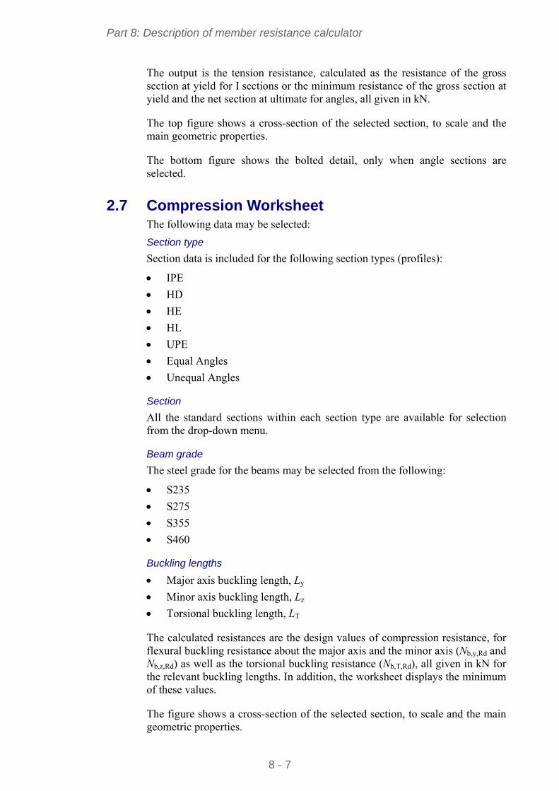
Part 8: Description of member resistance calculator
8 - 7
The output is the tension resistance, calculated as the resistance of the gross section at yield for I sections or the minimum resistance of the gross section at yield and the net section at ultimate for angles, all given in kN.
The top figure shows a cross-section of the selected section, to scale and the main geometric properties.
The bottom figure shows the bolted detail, only when angle sections are selected.
2.7 Compression Worksheet The following data may be selected:
Section type
Section data is included for the following section types (profiles):
IPE
HD
HE
HL
UPE
Equal Angles
Unequal Angles
Section
All the standard sections within each section type are available for selection from the drop-down menu.
Beam grade
The steel grade for the beams may be selected from the following:
S235
S275
S355
S460
Buckling lengths
Major axis buckling length, Ly
Minor axis buckling length, Lz
Torsional buckling length, LT
The calculated resistances are the design values of compression resistance, for flexural buckling resistance about the major axis and the minor axis (Nb,y,Rd and Nb,z,Rd) as well as the torsional buckling resistance (Nb,T,Rd), all given in kN for the relevant buckling lengths. In addition, the worksheet displays the minimum of these values.
The figure shows a cross-section of the selected section, to scale and the main geometric properties.
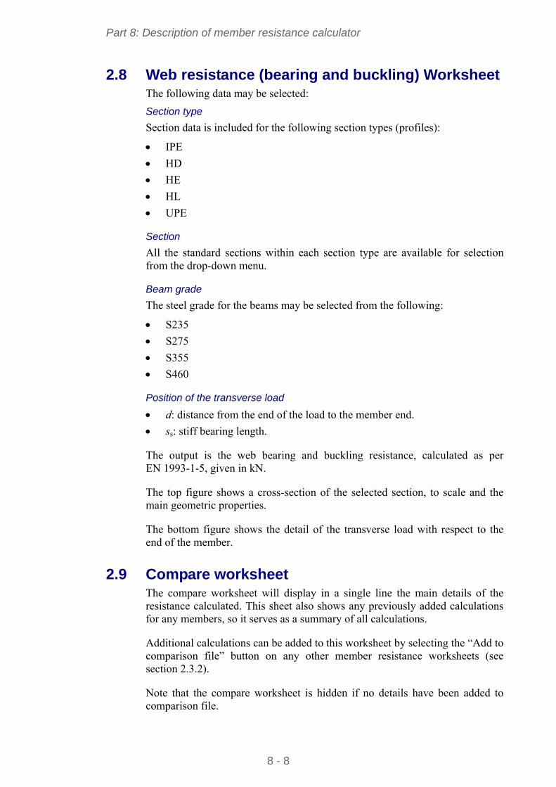
Part 8: Description of member resistance calculator
8 - 8
2.8 Web resistance (bearing and buckling) Worksheet The following data may be selected:
Section type
Section data is included for the following section types (profiles):
IPE
HD
HE
HL
UPE
Section
All the standard sections within each section type are available for selection from the drop-down menu.
Beam grade
The steel grade for the beams may be selected from the following:
S235
S275
S355
S460
Position of the transverse load
d: distance from the end of the load to the member end.
ss: stiff bearing length.
The output is the web bearing and buckling resistance, calculated as per EN 1993-1-5, given in kN.
The top figure shows a cross-section of the selected section, to scale and the main geometric properties.
The bottom figure shows the detail of the transverse load with respect to the end of the member.
2.9 Compare worksheet The compare worksheet will display in a single line the main details of the resistance calculated. This sheet also shows any previously added calculations for any members, so it serves as a summary of all calculations.
Additional calculations can be added to this worksheet by selecting the “Add to comparison file” button on any other member resistance worksheets (see section 2.3.2).
Note that the compare worksheet is hidden if no details have been added to comparison file.

Part 8: Description of member resistance calculator
8 - 9
2.9.1 Print comparison file
This button formats the comparison file and opens up the print window, where the user can select a printer and print.
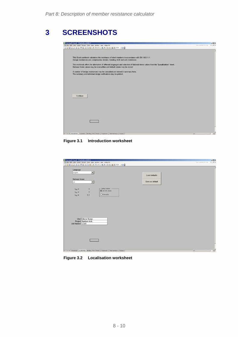
Part 8: Description of member resistance calculator
8 - 10
3 SCREENSHOTS
Figure 3.1 Introduction worksheet
Figure 3.2 Localisation worksheet
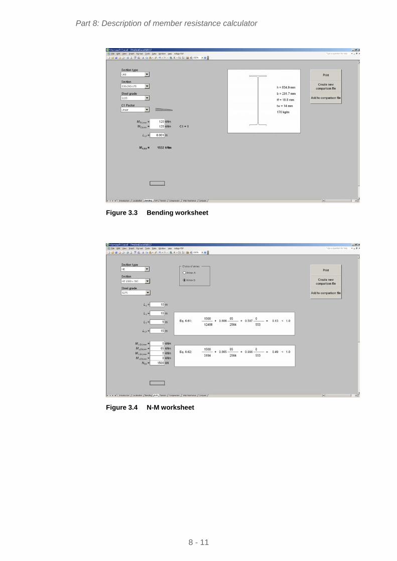
Part 8: Description of member resistance calculator
8 - 11
Figure 3.3 Bending worksheet
Figure 3.4 N-M worksheet
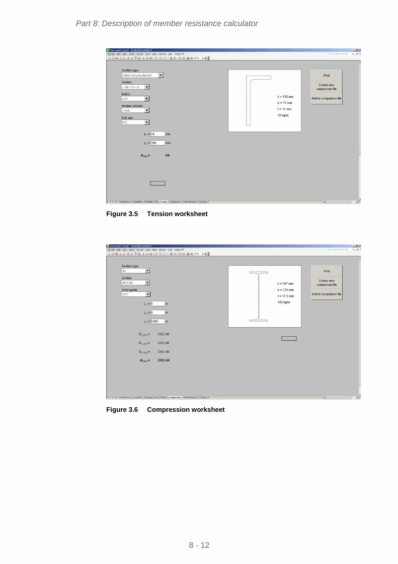
Part 8: Description of member resistance calculator
8 - 12
Figure 3.5 Tension worksheet
Figure 3.6 Compression worksheet
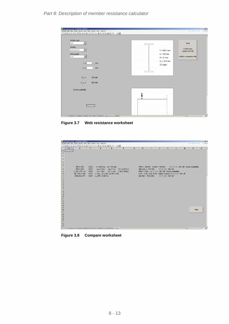
Part 8: Description of member resistance calculator
8 - 13
Figure 3.7 Web resistance worksheet
Figure 3.8 Compare worksheet

Part 8: Description of member resistance calculator
8 - 14
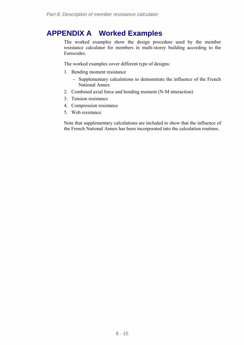
Part 8: Description of member resistance calculator
8 - 15
APPENDIX A Worked Examples The worked examples show the design procedure used by the member resistance calculator for members in multi-storey building according to the Eurocodes.
The worked examples cover different type of designs:
1. Bending moment resistance
Supplementary calculations to demonstrate the influence of the French National Annex
2. Combined axial force and bending moment (N-M interaction)
3. Tension resistance
4. Compression resistance
5. Web resistance
Note that supplementary calculations are included to show that the influence of the French National Annex has been incorporated into the calculation routines.
8 - 16
Worked Example 1: Bending moment resistance
1 of 3
Made by CZT Date 02/2010
Calculation sheet Checked by ENM Date 02/2010
1. Bending moment resistance This example presents the method used in the member resistance calculator for calculating the bending moment resistance, adopting the recommended values of EN 1993-1-1.
References are to EN 1993-1-1 unless otherwise stated
Section: IPE 500
Steel grade: S355
L = 3,8 m
1.1. Cross-section classification
1.1.1. The web
wt
c =
2,10
426 = 41,8
Table 5.2 (Sheet 1)
The limit for Class 1 is : 72ε = 72 0,81 = 58,3
Then : wt
c = 41,8 < 58,3
The web is class 1.
1.1.2. The flange
ft
c =
16
9,73= 4,6
The limit for Class 1 is : 9ε = 9 0,81 = 7,3
Then : ft
c = 4,6 < 8,3
The flange is Class 1
Table 5.2 (Sheet 2)
Therefore the section is Class 1. The verification of the member will be based on the plastic resistance of the cross-section.
1.2. Lateral-torsional buckling resistance, Mb,Rd
444 kNm
3800
0444
0 77,11 C
Appendix C of Single-Storey Steel Building, Part 4
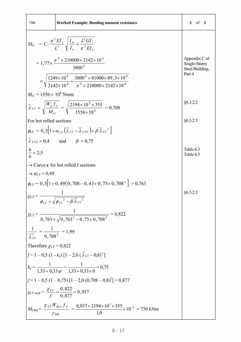
Title Worked Example: Bending moment resistance 2 of 3
8 - 17
Mcr = z
2
t2
z
w
2
z2
1EI
GIL
I
I
L
EIC
= 2
42
3800
10214221000077,1
42
42
4
9
102142210000
103,89810003800
102142
101249
Mcr = 1556 106 Nmm
Appendix C of Single-Storey Steel Building, Part 4
LT cr
yy
M
fW =
6
3
101556
355102194
= 0,708
§6.3.2.2
For hot rolled sections
LT = 2LTLT,0LTLT15,0
LT,0 0,4 and 0,75
§6.3.2.3
5,2b
h
Curve c for hot rolled I sections
LT 0,49
Table 6.3 Table 6.5
LT = 2708,075,04,0708,049,015,0 = 0,763
LT = 2
LT2
LTLT
1
LT = 22 708,075,0763,0763,0
1
= 0,822
§6.3.2.3
2LT
1
=
2708,0
1 = 1,99
Therefore LT = 0,822
f = 1 – 0,5 (1 - kc) [1 – 2,0 ( ])8,0 2LT
kc = 33,033,1
1
=
033,033,1
1
= 0,75
f = 1 – 0,5 (1 – 0,75) [1 – 2,0 (0,708 – 0,8)2] = 0,877
χLT mod = 937,0877,0
822,0LT f
Mb,Rd = M1
yypl,LT
fW = 6
3
100,1
355102194937,0
= 730 kNm
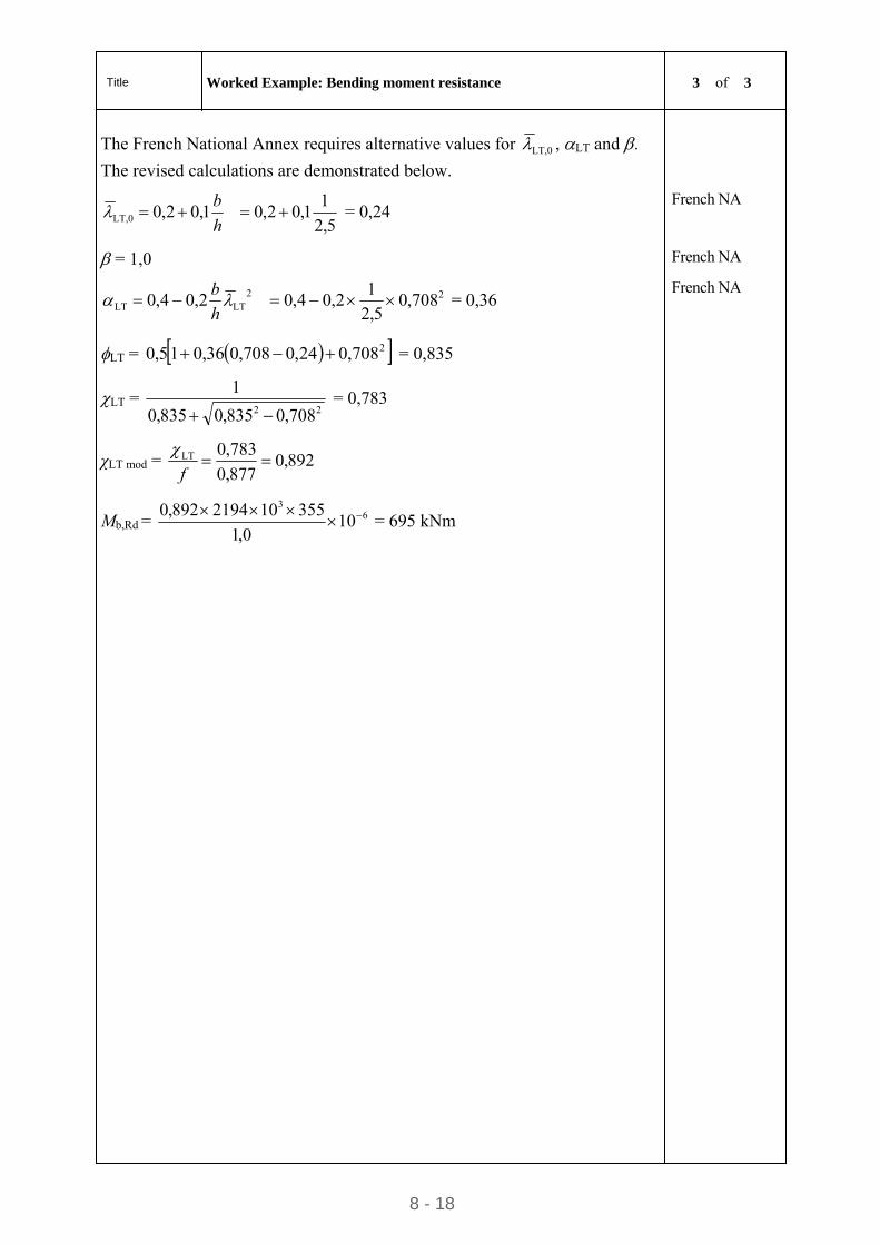
Title Worked Example: Bending moment resistance 3 of 3
8 - 18
The French National Annex requires alternative values for LT,0 , LT and .
The revised calculations are demonstrated below.
5,2
11,02,01,02,0LT,0
h
b = 0,24 French NA
= 1,0 French NA
22LTLT 708,0
5,2
12,04,02,04,0
h
b = 0,36
French NA
LT = 2708,024,0708,036,015,0 = 0,835
LT = 22 708,0835,0835,0
1
= 0,783
χLT mod = 892,0877,0
783,0LT f
Mb,Rd = 63
100,1
355102194892,0
= 695 kNm
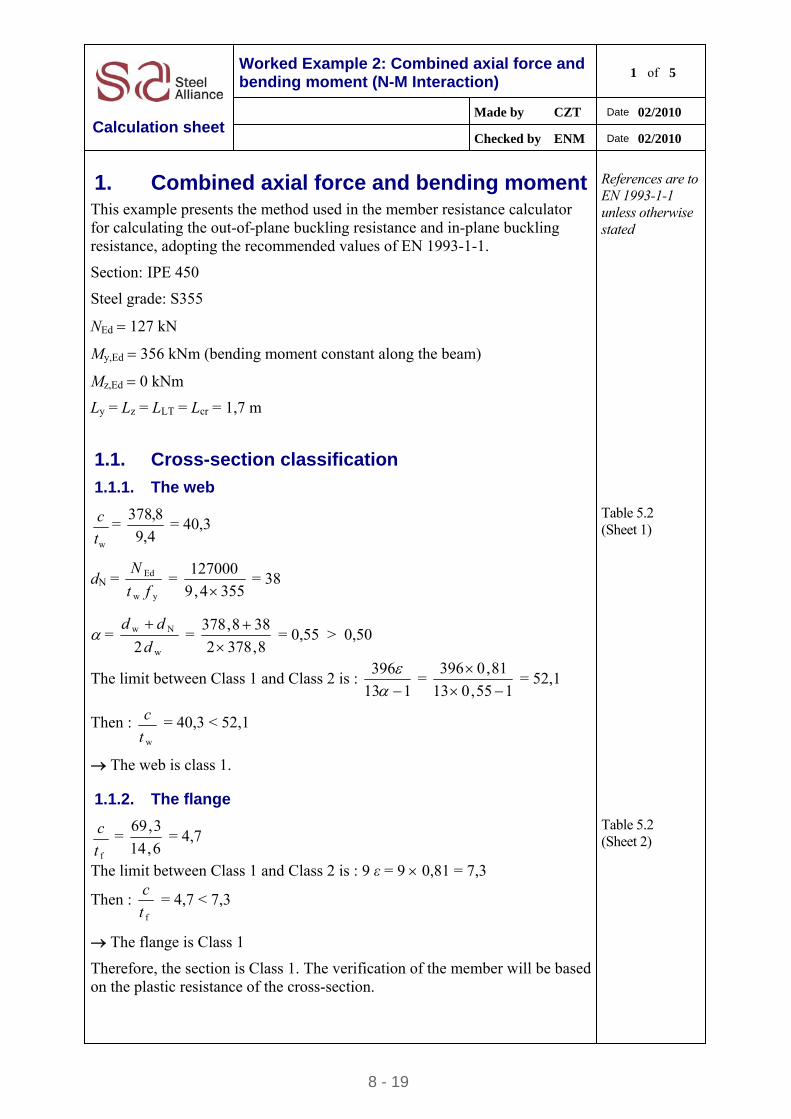
8 - 19
Worked Example 2: Combined axial force and bending moment (N-M Interaction)
1 of 5
Made by CZT Date 02/2010
Calculation sheet Checked by ENM Date 02/2010
1. Combined axial force and bending moment This example presents the method used in the member resistance calculator for calculating the out-of-plane buckling resistance and in-plane buckling resistance, adopting the recommended values of EN 1993-1-1.
References are to EN 1993-1-1 unless otherwise stated
Section: IPE 450
Steel grade: S355
NEd 127 kN
My,Ed 356 kNm (bending moment constant along the beam)
Mz,Ed 0 kNm
Ly = Lz = LLT = Lcr = 1,7 m
1.1. Cross-section classification
1.1.1. The web
wt
c = 4,9
8,378 = 40,3
Table 5.2 (Sheet 1)
dN = yw
Ed
ft
N =
3554,9
127000
= 38
= w
Nw
2d
dd =
8,3782
388,378
= 0,55 > 0,50
The limit between Class 1 and Class 2 is : 113
396
= 155,013
81,0396
= 52,1
Then : wt
c = 40,3 < 52,1
The web is class 1.
1.1.2. The flange
ft
c =
6,14
3,69 = 4,7
The limit between Class 1 and Class 2 is : 9 ε = 9 0,81 = 7,3
Then : ft
c = 4,7 < 7,3
The flange is Class 1
Table 5.2 (Sheet 2)
Therefore, the section is Class 1. The verification of the member will be based on the plastic resistance of the cross-section.
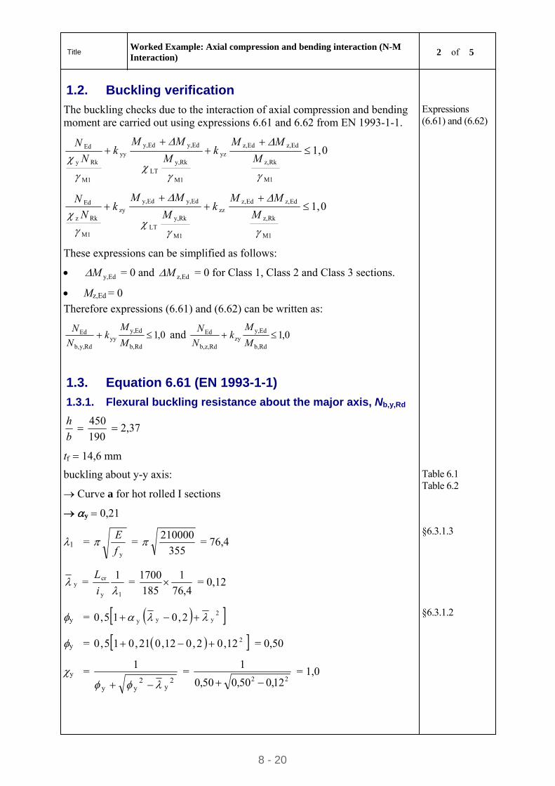
Title Worked Example: Axial compression and bending interaction (N-M Interaction)
2 of 5
8 - 20
1.2. Buckling verification
The buckling checks due to the interaction of axial compression and bending moment are carried out using expressions 6.61 and 6.62 from EN 1993-1-1.
0,1
M1
Rkz,
Edz,Edz,yz
M1
Rky,LT
Edy,Edy,yy
M1
Rky
Ed
M
MMk
M
MMk
N
N
0,1
M1
Rkz,
Edz,Edz,zz
M1
Rky,LT
Edy,Edy,zy
M1
Rkz
Ed
M
MMk
M
MMk
N
N
Expressions (6.61) and (6.62)
These expressions can be simplified as follows:
Edy,M = 0 and Edz,M = 0 for Class 1, Class 2 and Class 3 sections.
Mz,Ed = 0
Therefore expressions (6.61) and (6.62) can be written as:
0,1Rdb,
Edy,yy
Rdy,b,
Ed M
Mk
N
N and 0,1
Rdb,
Edy,zy
Rdz,b,
Ed M
Mk
N
N
1.3. Equation 6.61 (EN 1993-1-1)
1.3.1. Flexural buckling resistance about the major axis, Nb,y,Rd
b
h
190
450 2,37
tf 14,6 mm
buckling about y-y axis:
Curve a for hot rolled I sections
y 0,21
Table 6.1 Table 6.2
1 = yf
E = 355
210000 = 76,4 §6.3.1.3
y = 1y
cr 1
i
L =
4,76
1
185
1700 = 0,12
y = 2yyy 2,015,0
y = 212,02,012,021,015,0 = 0,50
§6.3.1.2
y = 2
y2
yy
1
=
22 12,050,050,0
1
= 1,0
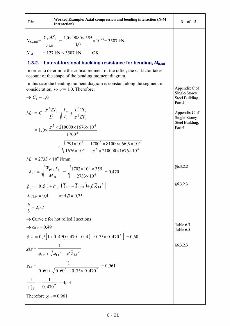
Title Worked Example: Axial compression and bending interaction (N-M Interaction)
3 of 5
8 - 21
Nb,y,Rd = M1
yy
Af
= 3100,1
35598800,1
= 3507 kN
NEd = 127 kN < 3507 kN OK
1.3.2. Lateral-torsional buckling resistance for bending, Mb,Rd
In order to determine the critical moment of the rafter, the C1 factor takes account of the shape of the bending moment diagram.
In this case the bending moment diagram is constant along the segment in consideration, so = 1,0. Therefore:
1C = 1,0
Appendix C of Single-Storey Steel Building, Part 4
Mcr = z
2
t2
z
w
2
z2
1EI
GIL
I
I
L
EIC
= 2
42
1700
1016762100000,1
42
42
4
9
101676210000
109,66810001700
101676
10791
Mcr = 2733 106 Nmm
Appendix C of Single-Storey Steel Building, Part 4
LT cr
yypl,
M
fW =
6
3
102733
355101702
= 0,470
§6.3.2.2
2LTLT,0LTLTLT 15,0 §6.3.2.3
LT,0 0,4 and 0,75
b
h 2,37
Curve c for hot rolled I sections
LT 0,49 Table 6.3 Table 6.5
2LT 470,075,04,0470,049,015,0 = 0,60
LT = 2
LT2
LTLT
1
LT = 22 470,075,060,060,0
1
= 0,961
§6.3.2.3
2LT
1
=
2470,0
1 = 4,53
Therefore LT = 0,961
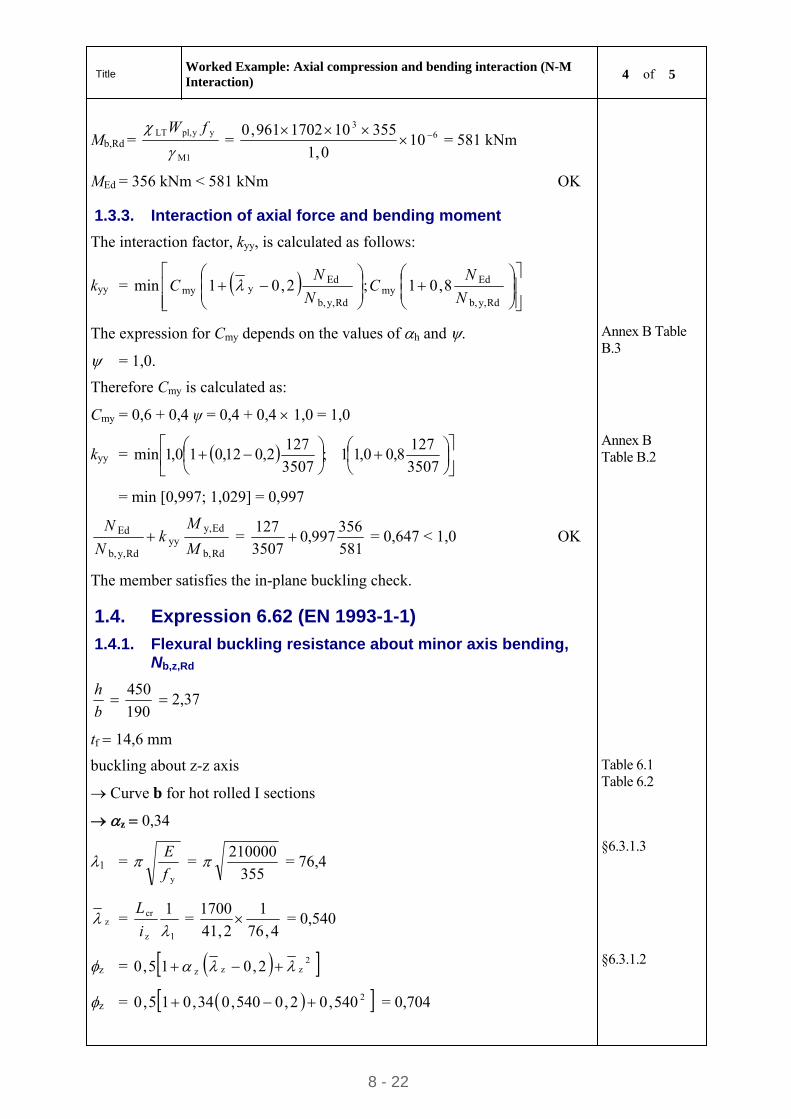
Title Worked Example: Axial compression and bending interaction (N-M Interaction)
4 of 5
8 - 22
Mb,Rd = M1
yypl,LT
fW
= 63
100,1
355101702961,0
= 581 kNm
MEd = 356 kNm < 581 kNm OK
1.3.3. Interaction of axial force and bending moment
The interaction factor, kyy, is calculated as follows:
kyy =
Rdy,b,
Edmy
Rdy,b,
Edymy 8,01;2,01min
N
NC
N
NC
The expression for Cmy depends on the values of h and .
= 1,0.
Therefore Cmy is calculated as:
Cmy = 0,6 + 0,4 ψ = 0,4 + 0,4 1,0 = 1,0
Annex B Table B.3
kyy =
3507
1278,00,11;
3507
1272,012,010,1min
= min [0,997; 1,029] = 0,997
Annex B Table B.2
Rdb,
Edy,yy
Rdy,b,
Ed
M
Mk
N
N =
581
356997,0
3507
127 = 0,647 < 1,0 OK
The member satisfies the in-plane buckling check.
1.4. Expression 6.62 (EN 1993-1-1)
1.4.1. Flexural buckling resistance about minor axis bending, Nb,z,Rd
b
h
190
450 2,37
tf 14,6 mm
buckling about z-z axis
Curve b for hot rolled I sections
z 0,34
Table 6.1 Table 6.2
1 = yf
E = 355
210000 = 76,4 §6.3.1.3
z = 1z
cr 1
i
L =
4,76
1
2,41
1700 = 0,540
z = 2zzz 2,015,0
z = 2540,02,0540,034,015,0 = 0,704
§6.3.1.2
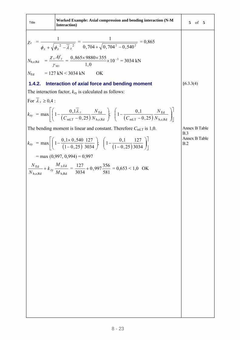
Title Worked Example: Axial compression and bending interaction (N-M Interaction)
5 of 5
8 - 23
z = 2
z2
zz
1
=
22 540,0704,0704,0
1
= 0,865
Nb,z,Rd = M1
yz
Af
= 3100,1
3559880865,0
= 3034 kN
NEd = 127 kN < 3034 kN OK
1.4.2. Interaction of axial force and bending moment §6.3.3(4)
The interaction factor, kzy is calculated as follows:
For z 0,4 :
kzy =
Rdz,b,
Ed
mLTRdz,b,
Ed
mLT 25,0
1,01;
25,0
1,01max
N
N
CN
N
Cz
The bending moment is linear and constant. Therefore CmLT is 1,0. Annex B Table B.3
kzy =
3034
127
25,01
1,01;
3034
127
25,01
540,01,01max
= max (0,997, 0,994) = 0,997
Annex B Table B.2
Rdb,
Edy,zy
Rdz,b,
Ed
M
Mk
N
N =
581
356997,0
3034
127 = 0,653 < 1,0 OK
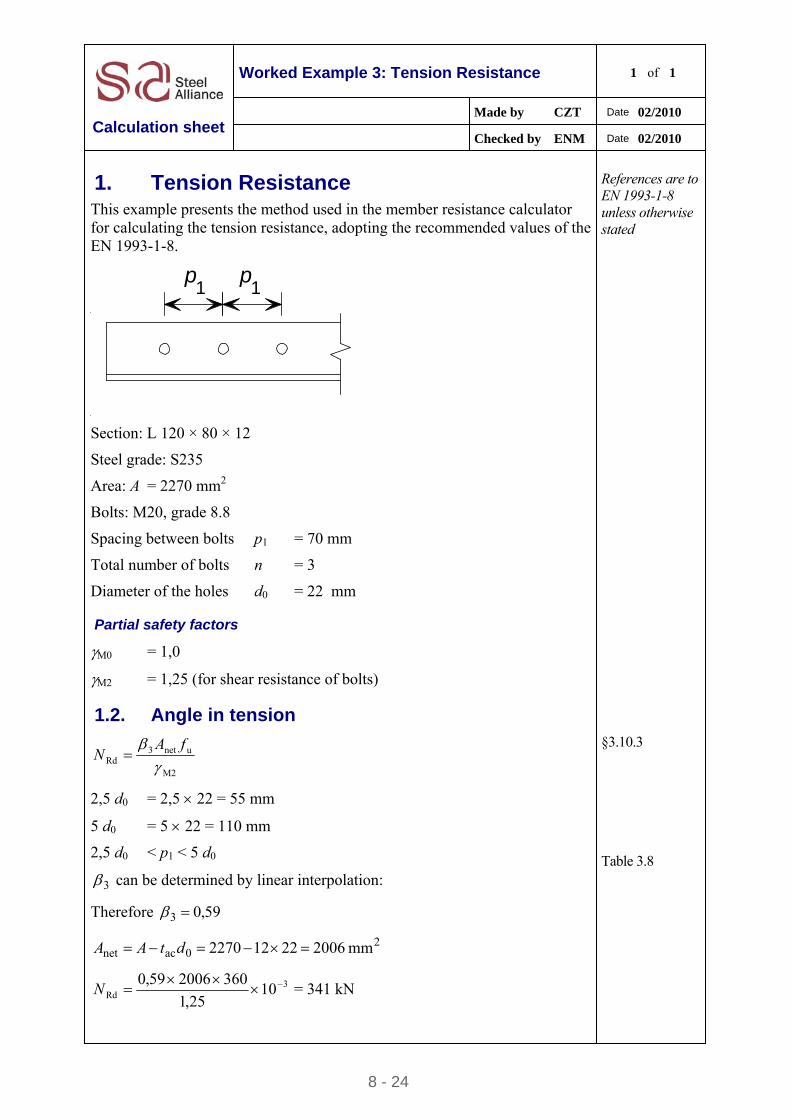
8 - 24
Worked Example 3: Tension Resistance 1 of 1
Made by CZT Date 02/2010
Calculation sheet Checked by ENM Date 02/2010
1. Tension Resistance This example presents the method used in the member resistance calculator for calculating the tension resistance, adopting the recommended values of the EN 1993-1-8.
References are to EN 1993-1-8 unless otherwise stated
p p1 1
Section: L 120 × 80 × 12
Steel grade: S235
Area: A = 2270 mm2
Bolts: M20, grade 8.8
Spacing between bolts p1 = 70 mm
Total number of bolts n = 3
Diameter of the holes d0 = 22 mm
Partial safety factors
M0 = 1,0
M2 = 1,25 (for shear resistance of bolts)
1.2. Angle in tension
M2
unet3Rd
fAN
§3.10.3
2,5 d0 = 2,5 22 = 55 mm
5 d0 = 5 22 = 110 mm
2,5 d0 < p1 < 5 d0 Table 3.8
3 can be determined by linear interpolation:
Therefore 59,03
20acnet mm 200622122270 dtAA
3Rd 10
25,1
360200659,0
N = 341 kN
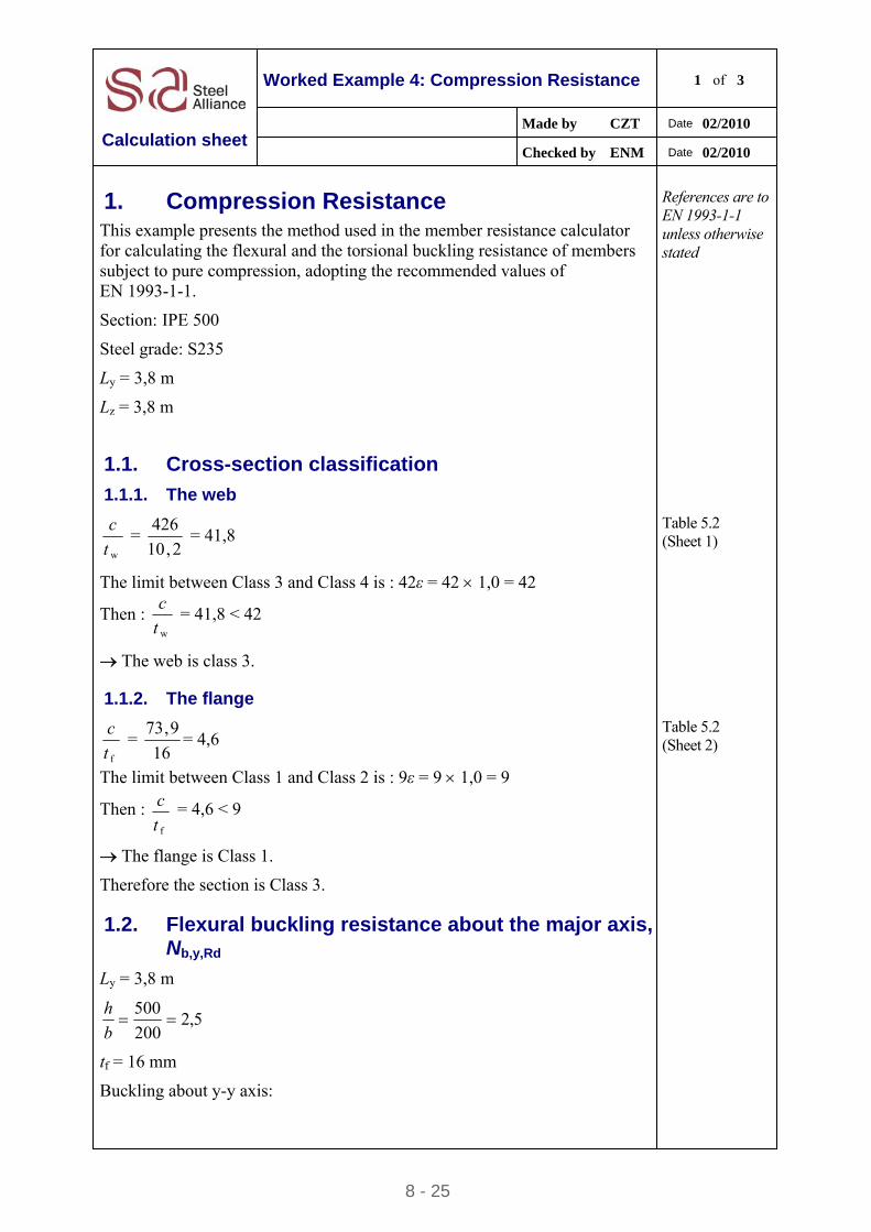
8 - 25
Worked Example 4: Compression Resistance 1 of 3
Made by CZT Date 02/2010
Calculation sheet Checked by ENM Date 02/2010
1. Compression Resistance This example presents the method used in the member resistance calculator for calculating the flexural and the torsional buckling resistance of members subject to pure compression, adopting the recommended values of EN 1993-1-1.
References are to EN 1993-1-1 unless otherwise stated
Section: IPE 500
Steel grade: S235
Ly = 3,8 m
Lz = 3,8 m
1.1. Cross-section classification
1.1.1. The web
wt
c =
2,10
426 = 41,8
Table 5.2 (Sheet 1)
The limit between Class 3 and Class 4 is : 42ε = 42 1,0 = 42
Then : wt
c = 41,8 < 42
The web is class 3.
1.1.2. The flange
ft
c =
16
9,73= 4,6
The limit between Class 1 and Class 2 is : 9ε = 9 1,0 = 9
Then : ft
c = 4,6 < 9
The flange is Class 1.
Table 5.2 (Sheet 2)
Therefore the section is Class 3.
1.2. Flexural buckling resistance about the major axis, Nb,y,Rd
Ly = 3,8 m
5,2200
500
b
h
tf = 16 mm
Buckling about y-y axis:
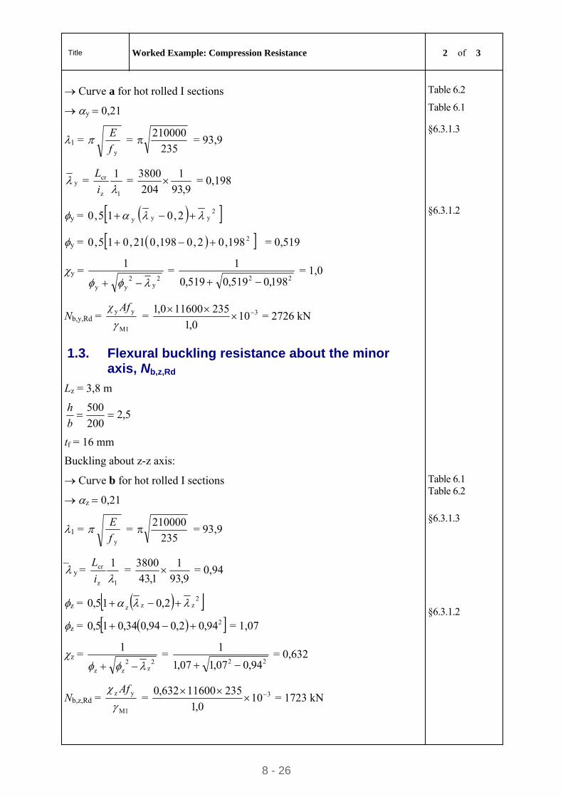
Title Worked Example: Compression Resistance 2 of 3
8 - 26
Curve a for hot rolled I sections
y 0,21
Table 6.2
Table 6.1
1 = yf
E = 235
210000 = 93,9
§6.3.1.3
y = 1z
cr 1
i
L =
9,93
1
204
3800 = 0,198
y = 2yyy 2,015,0
y = 2198,02,0198,021,015,0 = 0,519
§6.3.1.2
y = 2
y2
yy
1
=
22 198,0519,0519,0
1
= 1,0
Nb,y,Rd = M1
yy
Afχ
= 3100,1
352116000,1
= 2726 kN
1.3. Flexural buckling resistance about the minor axis, Nb,z,Rd
Lz = 3,8 m
5,2200
500
b
h
tf = 16 mm
Buckling about z-z axis:
Curve b for hot rolled I sections
z 0,21
Table 6.1 Table 6.2
1 = yf
E = 235
210000 = 93,9
§6.3.1.3
y = 1z
cr 1
i
L =
9,93
1
1,43
3800 = 0,94
z = 2zzz 2,015,0
z = 294,02,094,034,015,0 = 1,07
§6.3.1.2
z = 2
z2
zz
1
=
22 94,007,107,1
1
= 0,632
Nb,z,Rd = M1
yz
Af
= 3100,1
35211600632,0
= 1723 kN
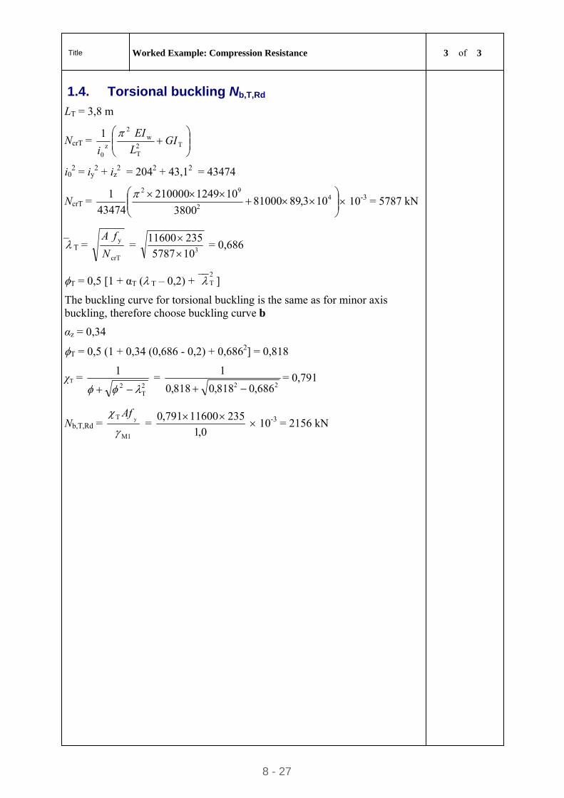
Title Worked Example: Compression Resistance 3 of 3
8 - 27
1.4. Torsional buckling Nb,T,Rd
LT = 3,8 m
NcrT =
T2
T
w2
z0
1GI
L
EI
i
i02 = iy
2 + iz2 = 2042 + 43,12 = 43474
NcrT =
42
92
103,89810003800
101249210000
43474
1 10-3 = 5787 kN
T = crT
y
N
fA =
3105787
23511600
= 0,686
T = 0,5 [1 + αT ( T – 0,2) +2T ]
The buckling curve for torsional buckling is the same as for minor axis buckling, therefore choose buckling curve b
αz = 0,34
T = 0,5 (1 + 0,34 (0,686 - 0,2) + 0,6862] = 0,818
χT = 2T
2
1
=
22 686,0818,0818,0
1
= 0,791
Nb,T,Rd = M1
T y
Af =
0,1
23511600791,0 10-3 = 2156 kN
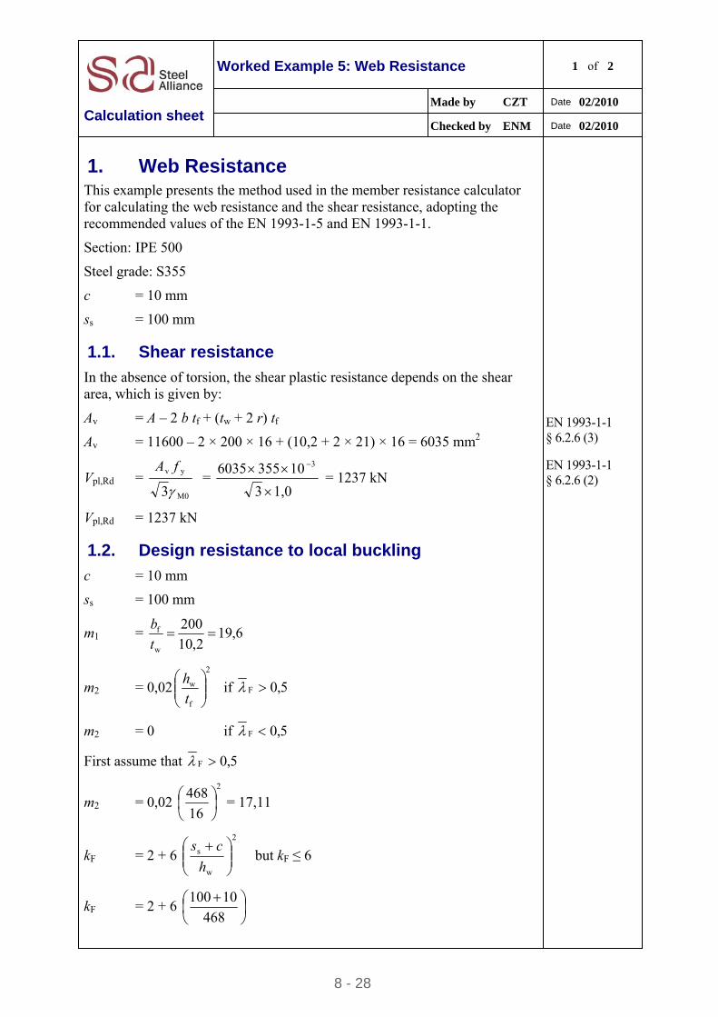
8 - 28
Worked Example 5: Web Resistance 1 of 2
Made by CZT Date 02/2010
Calculation sheet Checked by ENM Date 02/2010
1. Web Resistance This example presents the method used in the member resistance calculator for calculating the web resistance and the shear resistance, adopting the recommended values of the EN 1993-1-5 and EN 1993-1-1.
Section: IPE 500
Steel grade: S355
c = 10 mm
ss = 100 mm
1.1. Shear resistance
In the absence of torsion, the shear plastic resistance depends on the shear area, which is given by:
Av = A – 2 b tf + (tw + 2 r) tf
Av = 11600 – 2 × 200 × 16 + (10,2 + 2 × 21) × 16 = 6035 mm2
EN 1993-1-1 § 6.2.6 (3)
Vpl,Rd = 3 M0
yv
fA =
1,03
10 3556035 3
= 1237 kN
Vpl,Rd = 1237 kN
EN 1993-1-1 § 6.2.6 (2)
1.2. Design resistance to local buckling
c = 10 mm
ss = 100 mm
m1 = 6,192,10
200
w
f t
b
m2 = 0,022
f
w
t
h if 5,0F
m2 = 0 if 5,0F
First assume that 5,0F
m2 = 0,02 2
16
468
= 17,11
kF = 2 + 6 2
w
s
h
cs but kF ≤ 6
kF = 2 + 6
468
10100
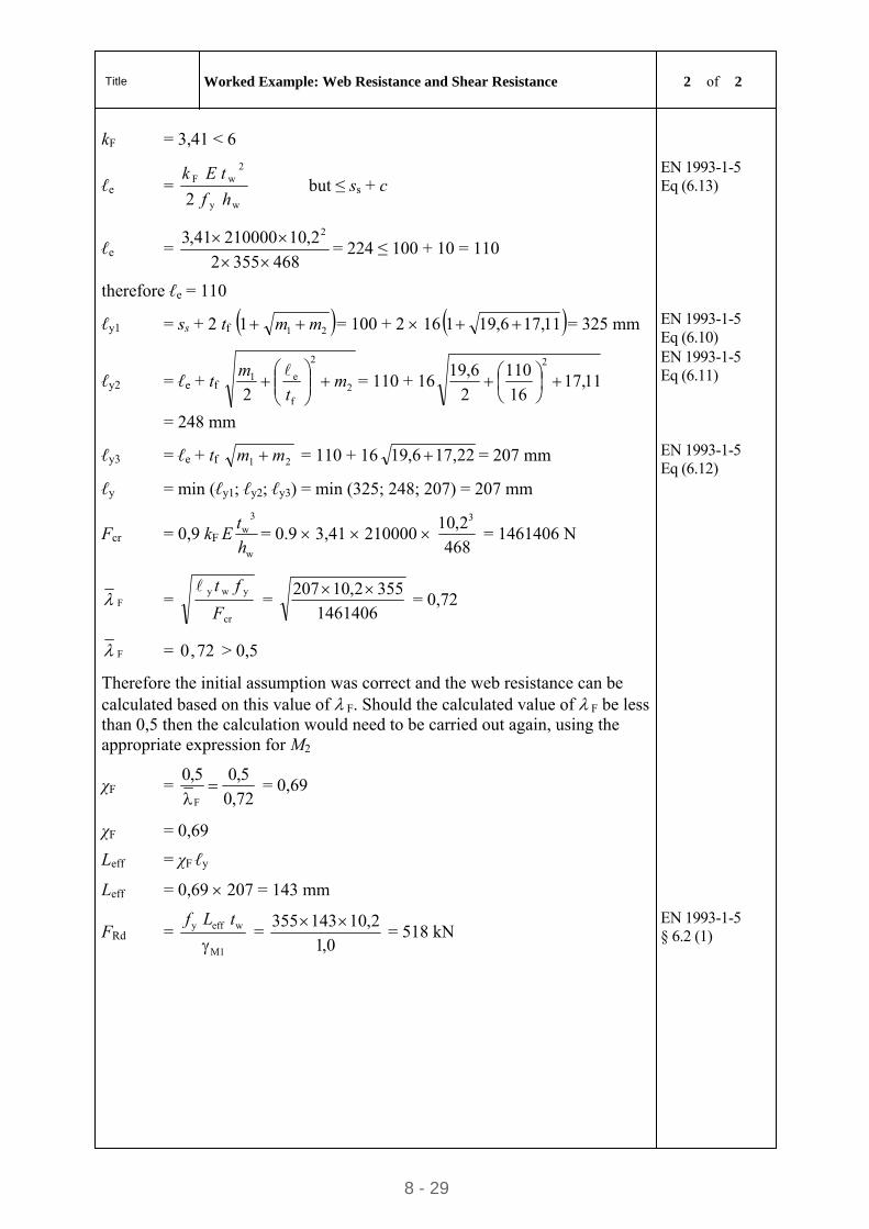
Title Worked Example: Web Resistance and Shear Resistance 2 of 2
8 - 29
kF = 3,41 < 6
ℓe = wy
2wF
2 hf
tEk but ≤ ss + c
EN 1993-1-5 Eq (6.13)
ℓe = 4683552
2,1021000041,3 2
= 224 ≤ 100 + 10 = 110
therefore ℓe = 110
ℓy1 = ss + 2 tf 211 mm = 100 + 2 16 11,176,191 = 325 mm EN 1993-1-5 Eq (6.10)
ℓy2 = ℓe + tf 2
2
f
e1
2m
t
m
= 110 + 16 11,17
16
110
2
6,192
= 248 mm
EN 1993-1-5 Eq (6.11)
ℓy3 = ℓe + tf 21 mm = 110 + 16 22,176,19 = 207 mm EN 1993-1-5 Eq (6.12)
ℓy = min (ℓy1; ℓy2; ℓy3) = min (325; 248; 207) = 207 mm
Fcr = 0,9 kFw
3w
h
tE = 0.9 3,41 210000
468
2,10 3
= 1461406 N
F = cr
ywy
F
ft =
1461406
3552,10207 = 0,72
F = 72,0 > 0,5
Therefore the initial assumption was correct and the web resistance can be calculated based on this value of F. Should the calculated value of F be less than 0,5 then the calculation would need to be carried out again, using the appropriate expression for M2
χF = 72,0
5,05,0
F
= 0,69
χF = 0,69
Leff = χF ℓy
Leff = 0,69 207 = 143 mm
FRd = 1M
weffy
tLf
= 0,1
2,10143355 = 518 kN
EN 1993-1-5 § 6.2 (1)
STEEL BUILDINGS IN EUROPE
Multi-storey Steel Buildings
Part 9: Description of simple
connection resistance calculator

Multi-Storey Steel Buildings
Part 9: Description of simple
connection resistance calculator

9 - ii
Part 9: Description of simple connection resistance calculator
FOREWORD
This publication is part nine of the design guide, Multi-Storey Steel Buildings.
The 10 parts in the Multi-Storey Steel Buildings guide are:
Part 1: Architect’s guide
Part 2: Concept design
Part 3: Actions
Part 4: Detailed design
Part 5: Joint design
Part 6: Fire Engineering
Part 7: Model construction specification
Part 8: Description of member resistance calculator
Part 9: Description of simple connection resistance calculator
Part 10: Guidance to developers of software for the design of composite beams
Multi-Storey Steel Buildings is one of two design guides. The second design guide is Single-Storey Steel Buildings.
The two design guides have been produced in the framework of the European project “Facilitating the market development for sections in industrial halls and low rise buildings (SECHALO) RFS2-CT-2008-0030”.
The design guides, and the associated software to which this document refers have been prepared under the direction of Arcelor Mittal, Peiner Träger and Corus. The technical content has been prepared by CTICM and SCI, collaborating as the Steel Alliance.
9 - 1

Part 9: Description of simple connection resistance calculator
9 - 2
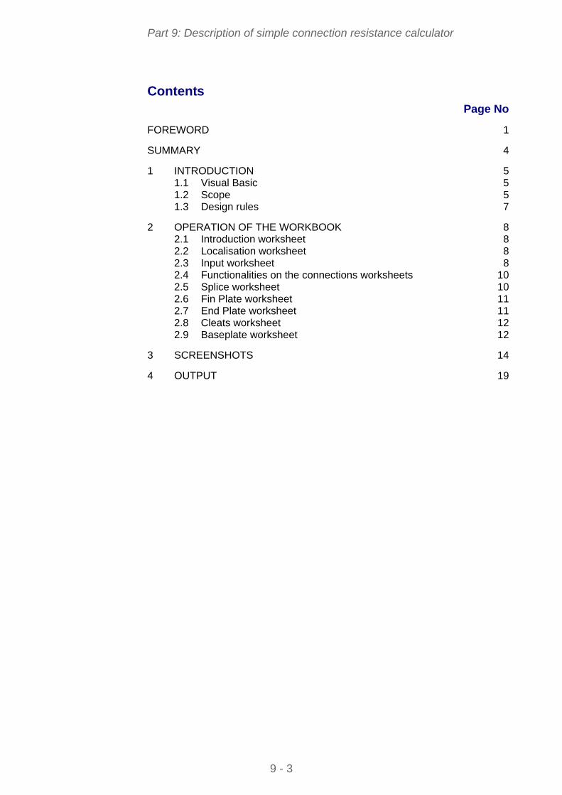
Part 9: Description of simple connection resistance calculator
Contents
Page No
FOREWORD 1
SUMMARY 4
1 INTRODUCTION 5 1.1 Visual Basic 5 1.2 Scope 5 1.3 Design rules 7
2 OPERATION OF THE WORKBOOK 8 2.1 Introduction worksheet 8 2.2 Localisation worksheet 8 2.3 Input worksheet 8 2.4 Functionalities on the connections worksheets 10 2.5 Splice worksheet 10 2.6 Fin Plate worksheet 11 2.7 End Plate worksheet 11 2.8 Cleats worksheet 12 2.9 Baseplate worksheet 12
3 SCREENSHOTS 14
4 OUTPUT 19
9 - 3

Part 9: Description of simple connection resistance calculator
SUMMARY
This document describes the connection resistance calculator, created in Excel, for typical, nominally pinned joints used in braced steel frames. It explains the scope of the workbook and lists the National Annexes and languages that are supported in the workbook. A description is given of each of the worksheets and the input information on each sheet. A screenshot of typical output is presented.
9 - 4
Part 9: Description of simple connection resistance calculator
1 INTRODUCTION
This document provides an introduction to the Excel workbook that covers the design of nominally pinned joints in accordance with EN 1993-1-8, as part of the design guide Multi-storey steel buildings. The workbook offers the alternative of different languages, and selection of National Annex values.
The operation of the workbook is described in Section 2. Screenshots of the various sheets in the workbook are contained in Section 3.
1.1 Visual Basic The spreadsheet depends on extensive visual basic code. Some users may have security settings set to disable such code.
The security level can be changed by selecting: “Tools”, “Options”. Select the “Security” tab and select “Macro security”. The setting must be at least “Medium”. Usually, Excel must be closed and re-started for the changes in security levels to become effective.
1.2 Scope 1.2.1 Joint types
The workbook covers nominally pinned joints that are commonly used in multi-storey steel structures. The types of connections covered in separate worksheets within the workbook are:
Partial depth flexible end plates (also known as header plates)
Fin plates
Double angle cleats
Column splices (bearing type)
Column bases.
For the beam connections, the resistance to both vertical shear and a horizontal tying force is calculated. The splice connections are all “bearing type”, meaning that there is no calculation of their resistance to axial compression. For splices, only the tensile resistance is calculated, for tying calculations. Only the resistance to axial compression is calculated for baseplates.
Each joint type is covered on a different worksheet. The default connection detail will be the recommended standardised detail.
Connection details are also drawn on each worksheet.
Connection resistances and drawn connection details are immediately updated as input data is modified by the user. The standardised details can be restored at any stage .
9 - 5

Part 9: Description of simple connection resistance calculator
If warnings are displayed on the diagrams because of some geometrical check not being satisfied, the drawing will not update. An updated drawing will only appear once the geometric warning has been resolved. Resolving one warning may then reveal a second problem, which must again be resolved before the drawing will update.
A more detailed table of the resistance of each connection component can be viewed and printed.
Connection classification
Beam and baseplate connections are assumed to be nominally pinned connections. Although the connections possess some rotational stiffness and some rotational strength, these are assumed to be sufficiently small that their influence can be ignored, and the assumption of pinned behaviour is valid.
EN 1993-1-8 requires connections to be classified. Connection classification may be made on the basis of calculations, or based on previous satisfactory experience. For each connection covered by the spreadsheet, standardised connections are proposed, which have sufficient use in practice to justify classification as nominally pinned on the basis of previous satisfactory experience.
Within each connection type, the user may modify a large range of variables, and thus produce a non-standardised connection. Designers should note that if connections other than the standardised solutions are adopted, the connection should be classified in accordance with EN 1993-1-8.
1.2.2 National Annex
The workbook includes National Annex values for M0, M1, M2 and c for the following countries:
The National Annexes covered are:
Belgium France Germany Italy Netherlands Poland Spain United Kingdom
For tying resistance, the spreadsheet adopts a value of Mu = 1.1.
The user has the option to overwrite the in-built National Annex values, allowing flexibility should the values be modified by the national standards body.
1.2.3 Languages
The language for input and output may be set by the user. The following languages are supported:
9 - 6
Part 9: Description of simple connection resistance calculator
French German Italian Polish Spanish English
1.3 Design rules The design resistance of each connection is evaluated in accordance with the Eurocodes and the guidance given in Multi-storey steel buildings. Part 5 Joint design.
9 - 7
Part 9: Description of simple connection resistance calculator
2 OPERATION OF THE WORKBOOK
2.1 Introduction worksheet The “introduction” sheet merely records the scope of the spreadsheet. On the initial loading of the workbook, this is the only worksheet tab visible. Choosing to “continue” reveals the remaining worksheet tabs.
2.2 Localisation worksheet The “localisation” sheet allows the user to select the language for the workbook and the National Annex (which determines the Nationally Determined Parameters (NDPs) that are to be used in calculations).
Checking the “overwrite” option allows the user to enter values of their choice. Deselecting this option leaves the National Annex selection as a blank – the user must select National Annex from the drop down menu.
Default settings of Language and National Annex may be saved. The values are written to a simple text file, stored in the same folder as the workbook file. Subsequent saving will merely overwrite this file.
Loading defaults will import whatever settings of language and National Annex that had previously been saved.
2.2.1 Material strength
The steel design strength is taken from Table 3.1 of EN 1993-1-1, or the product Standard, according to the choice in the National Annex.
Table 3.1 of EN 1993-1-1 covers material up to 80 mm thick. For thicknesses above 80 mm, the design strength is taken from the product Standard.
2.3 Input worksheet 2.3.1 Input information
Basic selection of section type, section, grade of main member, plates and bolts is made on the "Input" sheet. The options are described in the following Sections.
Section type
Section data is included for the following section types (profiles):
IPE HE HL HD
9 - 8
Part 9: Description of simple connection resistance calculator
Section
All the standard sections within each section type are available for selection from a drop-down menu.
Beam grade
The steel grade for the beams may be selected from the following:
S235 S275 S355 S460
Plate grade
The steel grade for end plates, fin plates, angle cleats and baseplates may be selected from the following:
S235 S275 S355 S460
Bolt class
The bolt class may be selected from the following:
4.6 5.6 8.8 10.9
Notes:
1. 8.8 bolts and S275 plates are considered standard. Connections may need to be classified in accordance with EN 1993-1-8 if other grades are selected.
2. The National Annex may restrict the choice of bolt class. Therefore the user has to choose a bolt class in accordance with national standards body.
User Information
The user may enter the following details:
User name Project name Job number
Any data entered will appear on the printed output.
2.3.2 Operation
Selecting a different section, changing grade of beam or plate, or changing the bolt class triggers a re-calculation of the connection resistances.
In every case, a standardised connection is presented as the default.
9 - 9
Part 9: Description of simple connection resistance calculator
If a very small section is selected, where the section is simply too shallow for a standardised end plate, fin plate, double angle cleat and splice connection, a warning appears, and only the baseplate tab remains visible.
The remaining tabs will appear once a sufficiently large member is selected.
2.4 Functionalities on the connections worksheets Each of the worksheets for splice, fin plate, end plate, cleats and baseplate have two buttons – “Review Summary” and “Use Std detail”.
2.4.1 Review summary
This button opens a further sheet, containing fuller details of the resistances calculated for each component of the connection. From this new sheet, the summary may be printed, or the user may return to the main spreadsheet.
2.4.2 Use Std Detail
This button restores the standardised connection.
2.5 Splice worksheet A standardised connection is presented, displaying values of tying resistance (axial tension). The critical design criterion is noted. The splices are “bearing type” transferring compression by direct bearing.
If the serial sizes are identical, a second splice option is displayed, with internal splice plates, and a second resistance is displayed.
Sections may be chosen for both top and bottom columns – they must however be the same section type.
The top section cannot be deeper (h) than the lower section. If an attempt is made to choose this configuration, the spreadsheet warns the user, and then adopts the latest section chosen for both top and bottom columns.
The top section cannot be significantly smaller than the bottom section. When the user attempts to choose a top section that is significantly smaller than the bottom section, a warning is displayed. The difference in section depths (h) must be less than 100 mm. The section may be drawn, but no resistance is displayed if the difference in section depth exceeds 100 mm. If the section depths are significantly different, several warnings may be displayed.
The following details of the standardised connection may be changed:
Section type Section (top and bottom) Grade Plate grade Cover plate thickness Cover plate width Bolt diameter Number of bolt rows
9 - 10
Part 9: Description of simple connection resistance calculator
Gauge (horizontal bolt spacing) Pitch (vertical bolt spacing) End distance (end distance on plate, from top and bottom pair of bolts)
In some cases, the member flange is so thick that the standard offset distance is insufficient, and a standardised connection is not possible. A warning will appear with this information.
End, edge and geometrical distances are checked, and warnings appear as required.
2.6 Fin Plate worksheet A standardised connection is presented, displaying values of vertical shear resistance and tying resistance. The critical design criterion is noted for both shear and tying.
The following details of the standardised connection may be changed:
Plate thickness Bolt diameter Bolt rows Lines of bolts (a single or double line) Gauge (horizontal bolt spacing – only relevant if two columns of bolts are
chosen) Pitch (vertical bolt spacing) End distance (end distance on plate, from top and bottom pair of bolts) Edge distance (on the fin plate) Beam end distance Plate offset (distance from top of beam to top of plate)
In some cases, the member flange is so thick that the standard offset distance is insufficient, and a standardised connection is not possible. A warning will appear with this information.
End, edge and geometrical distances are checked, and warnings appear as required.
The weld is sized to be full strength – no adjustment by the user is possible.
2.7 End Plate worksheet A standardised connection is presented, displaying design values of vertical shear resistance and tying resistance. The critical design criterion is noted for both shear and tying.
The following details of the standardised connection may be changed:
Plate thickness Bolt diameter Bolt rows Gauge (horizontal bolt spacing)
9 - 11
Part 9: Description of simple connection resistance calculator
Pitch (vertical bolt spacing) Plate width End distance (end distance on plate, from top and bottom pair of bolts) Offset (distance from top of beam to top of plate)
In some cases, the member flange is so thick that the standard offset distance is insufficient, and a standardised connection is not possible. A warning will appear with this information.
End, edge and geometrical distances are checked, and warnings appear as required.
The weld is sized to be full strength – no adjustment by the user is possible.
2.8 Cleats worksheet A standardised connection is presented, displaying values of vertical shear resistance and tying resistance. The critical design criterion is noted for both shear and tying.
The following details of the standardised connection may be changed:
Angle thickness Bolt diameter Bolt rows Leg length Back mark (bolt distance from heel of the angle) Lines of bolts (a single or double line) Gauge (horizontal bolt spacing – only if two columns of bolts are chosen) Pitch (vertical bolt spacing) End distance (end distance on plate, from top and bottom pair of bolts) Beam end distance Plate offset (distance from top of beam to top of plate)
In some cases, the member flange is so thick that the standard offset distance is insufficient, and a standardised connection is not possible. A warning will appear with this information.
End, edge and geometrical distances are checked, and warnings appear as required.
2.9 Baseplate worksheet A standardised connection is presented, displaying the value of the axial resistance.
The calculation of the design bearing strength, fjd assumes that = 1,5. The foundation joint material coefficient, j is taken as 2/3.
The following details of the standardised connection may be changed:
Grade of concrete
9 - 12
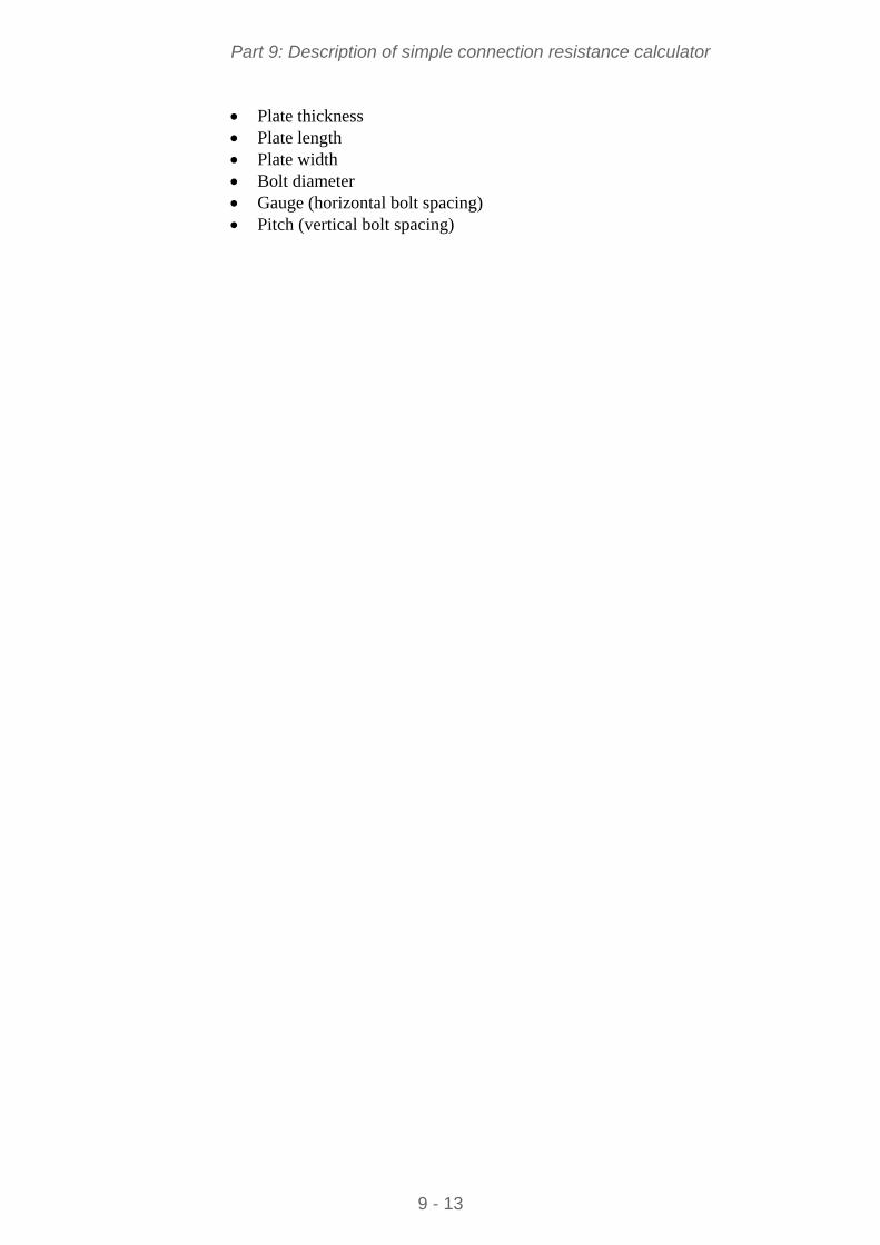
Part 9: Description of simple connection resistance calculator
Plate thickness Plate length Plate width Bolt diameter Gauge (horizontal bolt spacing) Pitch (vertical bolt spacing)
9 - 13
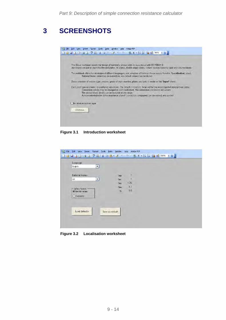
Part 9: Description of simple connection resistance calculator
3 SCREENSHOTS
Figure 3.1 Introduction worksheet
Figure 3.2 Localisation worksheet
9 - 14
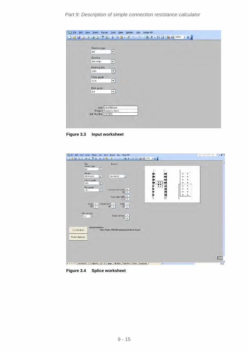
Part 9: Description of simple connection resistance calculator
Figure 3.3 Input worksheet
Figure 3.4 Splice worksheet
9 - 15
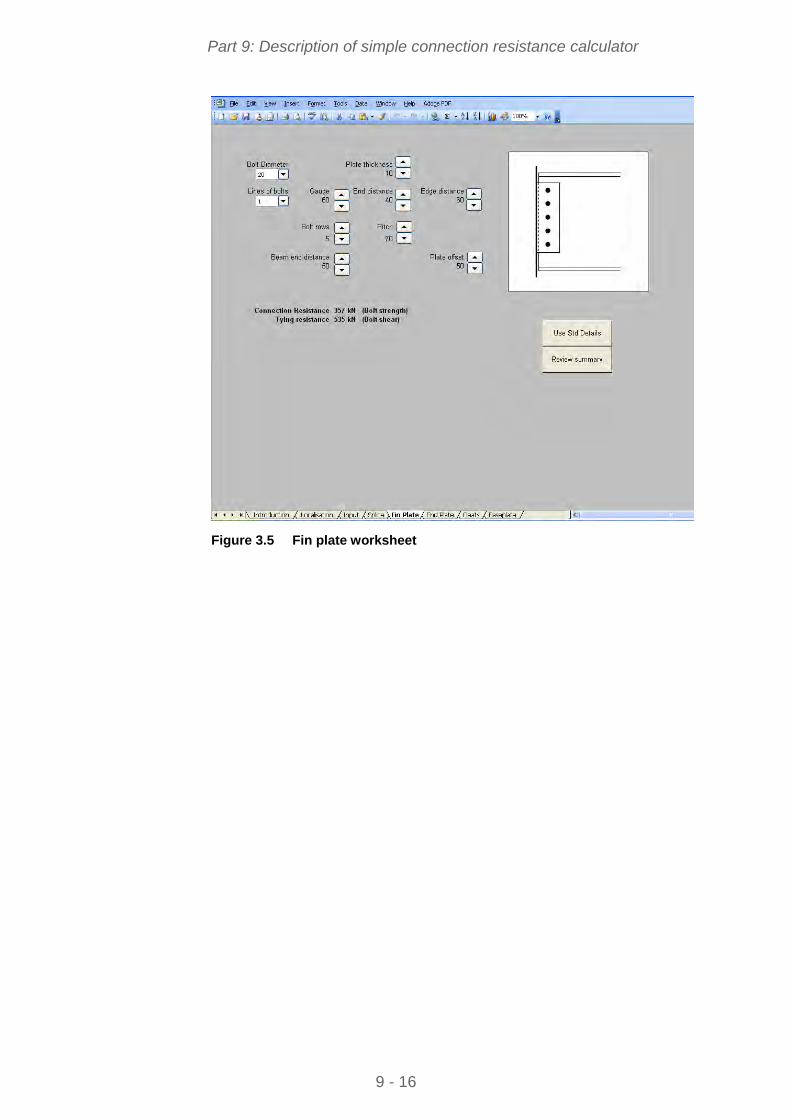
Part 9: Description of simple connection resistance calculator
Figure 3.5 Fin plate worksheet
9 - 16
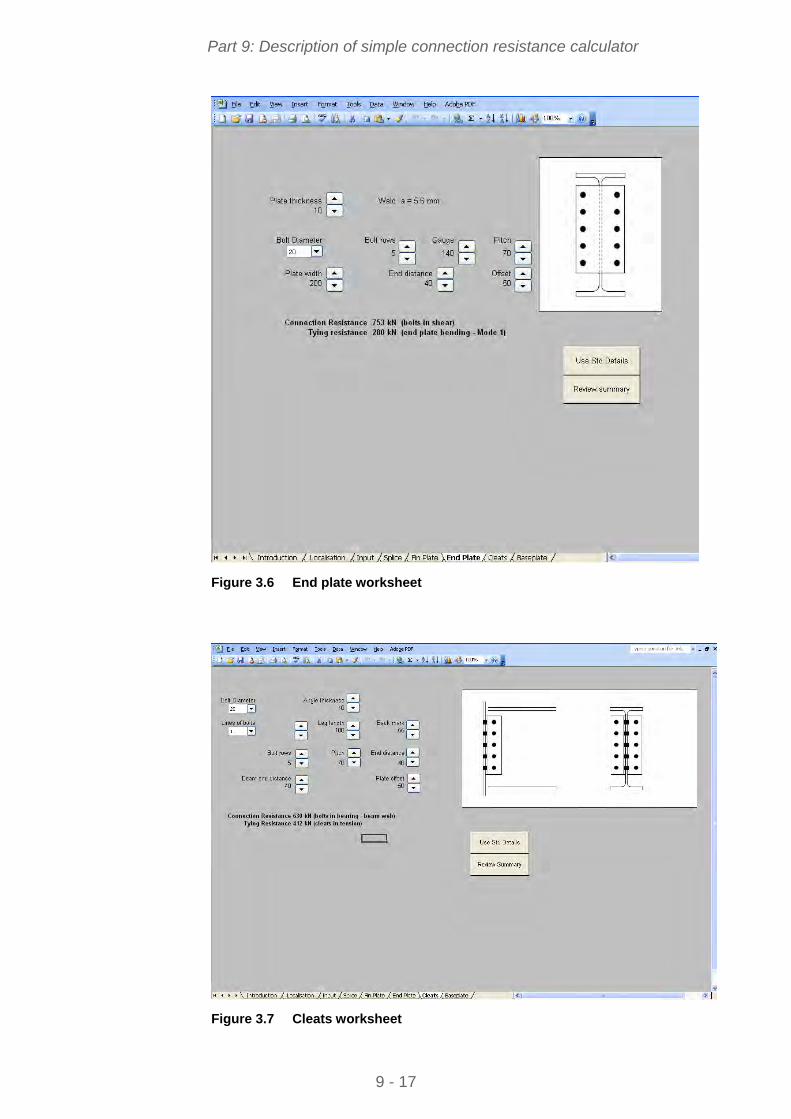
Part 9: Description of simple connection resistance calculator
Figure 3.6 End plate worksheet
Figure 3.7 Cleats worksheet
9 - 17
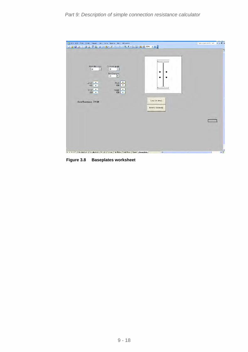
Part 9: Description of simple connection resistance calculator
Figure 3.8 Baseplates worksheet
9 - 18
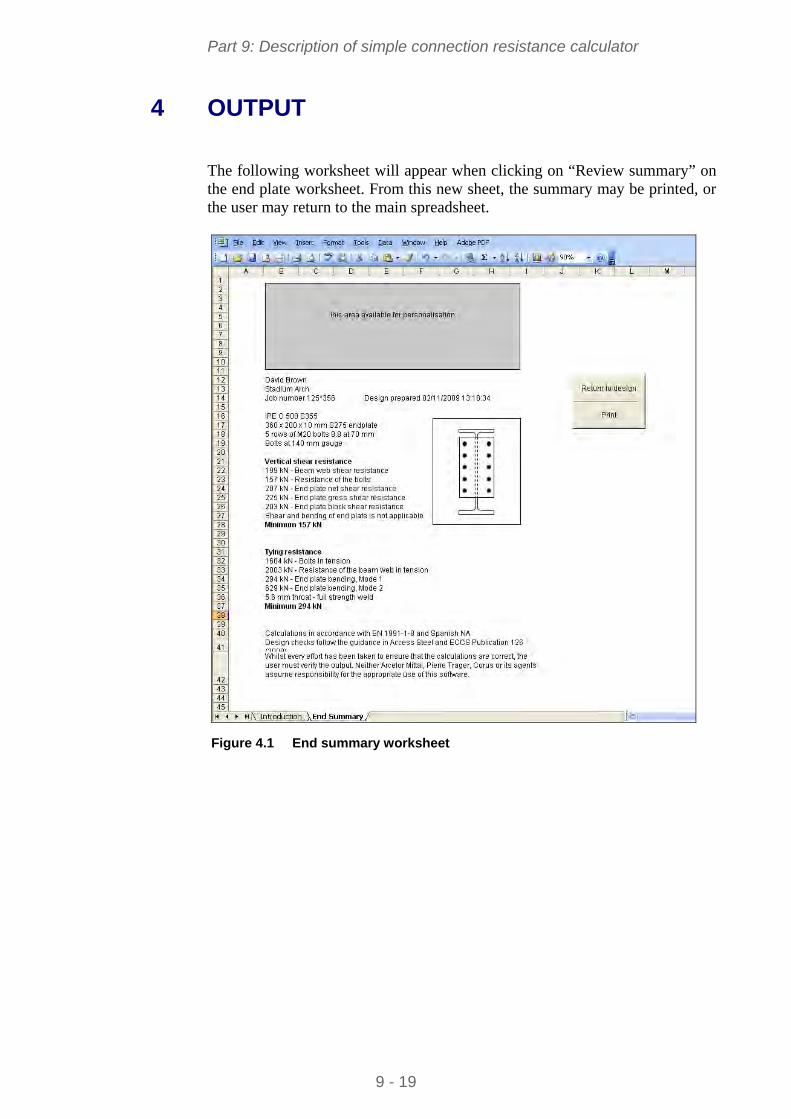
Part 9: Description of simple connection resistance calculator
9 - 19
4 OUTPUT
The following worksheet will appear when clicking on “Review summary” on the end plate worksheet. From this new sheet, the summary may be printed, or the user may return to the main spreadsheet.
Figure 4.1 End summary worksheet
STEEL BUILDINGS IN EUROPE
Multi-Storey Steel Buildings
Part 10: Guidance to developers of
software for the design of
composite beams

Multi-Storey Steel Buildings
Part 10: Guidance to developers of
software for the design of
composite beams

10 - ii
Part 10: Guidance to developers of software for the design of composite beams
FOREWORD
This publication is a second part of a design guide, Multi-Storey Steel Buildings.
The 10 parts in the Multi-Storey Steel Buildings guide are:
Part 1: Architect’s guide
Part 2: Concept design
Part 3: Actions
Part 4: Detailed design
Part 5: Joint design
Part 6: Fire Engineering
Part 7: Model construction specification
Part 8: Description of member resistance calculator
Part 9: Description of simple connection resistance calculator
Part 10: Guidance to developers of software for the design of composite beams
Multi-Storey Steel Buildings is one of two design guides. The second design guide is Single-Storey Steel Buildings.
The two design guides have been produced in the framework of the European project “Facilitating the market development for sections in industrial halls and low rise buildings (SECHALO) RFS2-CT-2008-0030”.
The design guides have been prepared under the direction of Arcelor Mittal, Peiner Träger and Corus. The technical content has been prepared by CTICM and SCI, collaborating as the Steel Alliance.
10 - iii

Part 10: Guidance to developers of software for the design of composite beams
10 - iv
Part 10: Guidance to developers of software for the design of composite beams
Contents Page No
FOREWORD iii
SUMMARY vi
1 SCOPE 7
2 BASIC DATA 8 2.1 General parameters of the beam 8 2.2 Steel section 9 2.3 Concrete slab 9 2.4 Shear connection 10 2.5 Loads 11 2.6 Partial factors 12 2.7 Other design parameters 12
3 MATERIAL PROPERTIES 13 3.1 Structural steel 13 3.2 Reinforcement steel bars 13 3.3 Concrete 13
4 CALCULATION OF INTERNAL FORCES AND MOMENTS 14 4.1 General 14 4.2 Effects of a point load 14 4.3 Effects of a uniformly distributed surface load 15 4.4 Combinations of actions 15
5 CONSTRUCTION STAGE 16 5.1 General 16 5.2 ULS verifications 16 5.3 SLS Calculations 20
6 FINAL STAGE 21 6.1 Effective width of the slab 21 6.2 Shear connection 21 6.3 Cross-section resistance 24 6.4 Longitudinal shear resistance 29 6.5 Serviceability limit states 31
7 LIST OF THE MAIN OUTPUTS 33
REFERENCES 34
Appendix A Overall flowchart 35
10 - v

Part 10: Guidance to developers of software for the design of composite beams
10 - vi
SUMMARY
This guide provides guidance to developers of software for the design of composite beams used in multi-storey buildings, according to the Eurocodes. It covers simply supported beams connected to the concrete slab using shear studs and gives technical requirements. The ULS verifications are to be based on plastic design.
Part 10: Guidance to developers of software for the design of composite beams
1 SCOPE
This document is aimed at software developers to enable them to develop a simple software tool for the design of composite beams in multi-storey buildings, according to EN 1994-1-1[1]. This document can also been regarded as a guide to understand the functioning of existing software in the same field of application.
This guide does not contain programming code; it only contains detailed technical requirements.
This document covers simply supported composite beams comprising a rolled profile connected by welded shear studs to a concrete slab. Several options are considered:
Primary or secondary beams
Plain slab or slab with profiled steel sheeting
Fully propped or unpropped beams during construction.
These technical requirements include:
The calculation of internal forces and moments
The verifications of the beam for ULS
The calculations for SLS
The calculation of the composite beam is based on the plastic resistance using full or partial connection.
The design procedure is summarized in the flowcharts given in Appendix A.
10 - 7
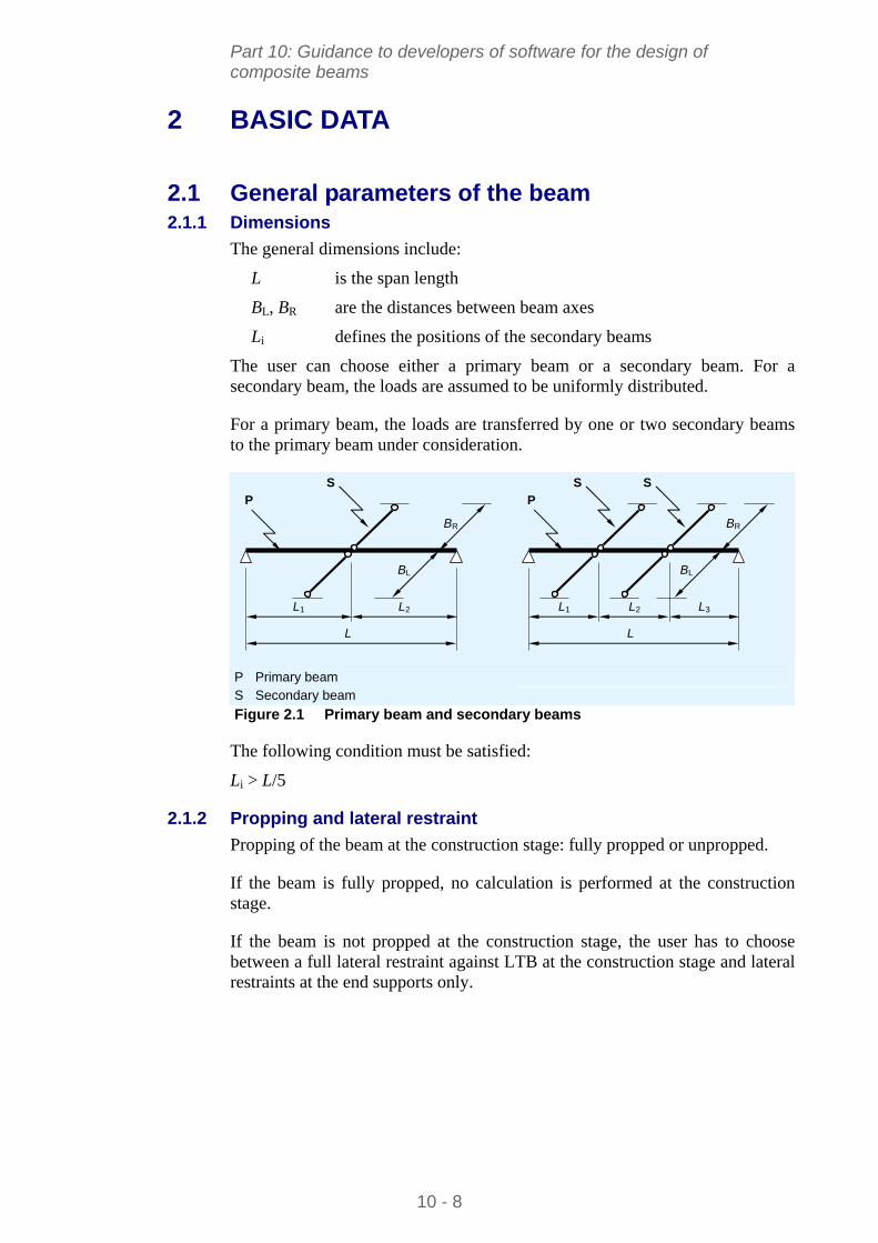
Part 10: Guidance to developers of software for the design of composite beams
2 BASIC DATA
2.1 General parameters of the beam 2.1.1 Dimensions
The general dimensions include:
L is the span length
BL, BR are the distances between beam axes
Li defines the positions of the secondary beams
The user can choose either a primary beam or a secondary beam. For a secondary beam, the loads are assumed to be uniformly distributed.
For a primary beam, the loads are transferred by one or two secondary beams to the primary beam under consideration.
BR
BL
L
P
S
L1 L2
P Primary beam
BR
BL
L
S Secondary beam
P
L1 L2 L3
S S
Figure 2.1 Primary beam and secondary beams
The following condition must be satisfied:
Li > L/5
2.1.2 Propping and lateral restraint
Propping of the beam at the construction stage: fully propped or unpropped.
If the beam is fully propped, no calculation is performed at the construction stage.
If the beam is not propped at the construction stage, the user has to choose between a full lateral restraint against LTB at the construction stage and lateral restraints at the end supports only.
10 - 8
Part 10: Guidance to developers of software for the design of composite beams
2.2 Steel section The structural steel section is a hot rolled I-section defined by its geometry:
h is the depth of the structural steel section
b is the flange width
tf is the flange thickness
tw is the web thickness
r is the root radius.
The following section properties can be obtained from an appropriate database:
A is the section area
Av,z is the shear area, according to EN 1993-1-1 § 6.2.6(3)
Iy is the second moment of area about the strong axis
Iz is the second moment of area about the weak axis
It is the torsion constant
Iw is the warping constant
Wel,y is the elastic modulus about the strong axis
Wpl,y is the plastic modulus about the strong axis.
The steel grade can be selected from the following list:
S235, S275, S355, S420, S460
2.3 Concrete slab The concrete slab is defined by:
The type of slab: either plain slab or slab with profiled steel sheeting
hf is the slab thickness
is the concrete density
The concrete class can be chosen from:
- C20/25
- C25/30
- C30/37
- C35/45
- C40/50
- C45/55
- C50/60
- C55/67
- C60/75
10 - 9
Part 10: Guidance to developers of software for the design of composite beams
The profiled steel sheeting, if used, is defined by its section geometry (Figure 2.2):
hp is the overall depth of the profiled steel sheeting
tp is the sheeting thickness
bs is the distance between centres of adjacent ribs
br is the width of rib
bb is the width of the bottom of the rib.
bs
hp
bb
tp br
Figure 2.2 Cross-section of a profiled steel sheeting
One of the following options has to be selected:
Ribs perpendicular to the beam
Ribs parallel to the beam axis.
When the profiled steel sheeting is perpendicular to the beam axis, one of the following options has to be selected:
Studs welded through the profiled steel sheeting
Profiled steel sheeting with holes for studs
Profiled steel sheeting interrupted on the beam (free positioning of the studs along the beam axis).
2.4 Shear connection 2.4.1 Description of a stud
The connectors are headed studs welded on the upper flange of the steel profile. For a given beam, all the studs are identical.
A stud is defined by:
hsc is the overall nominal height.
d is the shank diameter that can be selected from the following list: – 16 mm – 19 mm – 22 mm
fu,sc is the ultimate limit strength of the stud material.
10 - 10
Part 10: Guidance to developers of software for the design of composite beams
2.4.2 Positioning of the connectors
The position of the connectors can be defined over 1, 2 or 3 segments of the beam. For more than one segment, the length of each segment has to be given. The sum of these lengths should be equal to the length of the beam.
For each segment, the following parameters have to be defined:
The number of rows: 1 or 2
The distance between two consecutive connectors along the beam.
When a profiled steel sheeting is perpendicular to the beam, the distance between studs is n bs, where n can be equal to 1, 2 or 3.
2.5 Loads The software allows the user to define elementary load cases that are used in the combinations of actions for ULS and SLS according to EN 1990[2].
Only gravity loads are considered (downwards).
Up to three elementary load cases are considered within these specifications:
1 permanent load case, denoted G
2 variable load cases, denoted Q1 and Q2
For each load case, it is possible to define a uniformly distributed surface load qsurf. For a beam defined as “secondary beam”, a linear distributed load is derived:
qlin = qsurf (BL + BR)/2
where:
BL and BR are the distances between beams (left and right).
For a beam defined as “primary beam”, one or two point loads are derived from the distributed surface load.
The self weight of the rolled profile and the weight of the concrete slab are automatically calculated.
For each variable load case, the combination factors 0, 1 and 2 have to be defined.
When the beam is unpropped at the construction stage, a construction load should be defined by the user. The default value is 0,75 kN/m2.
10 - 11
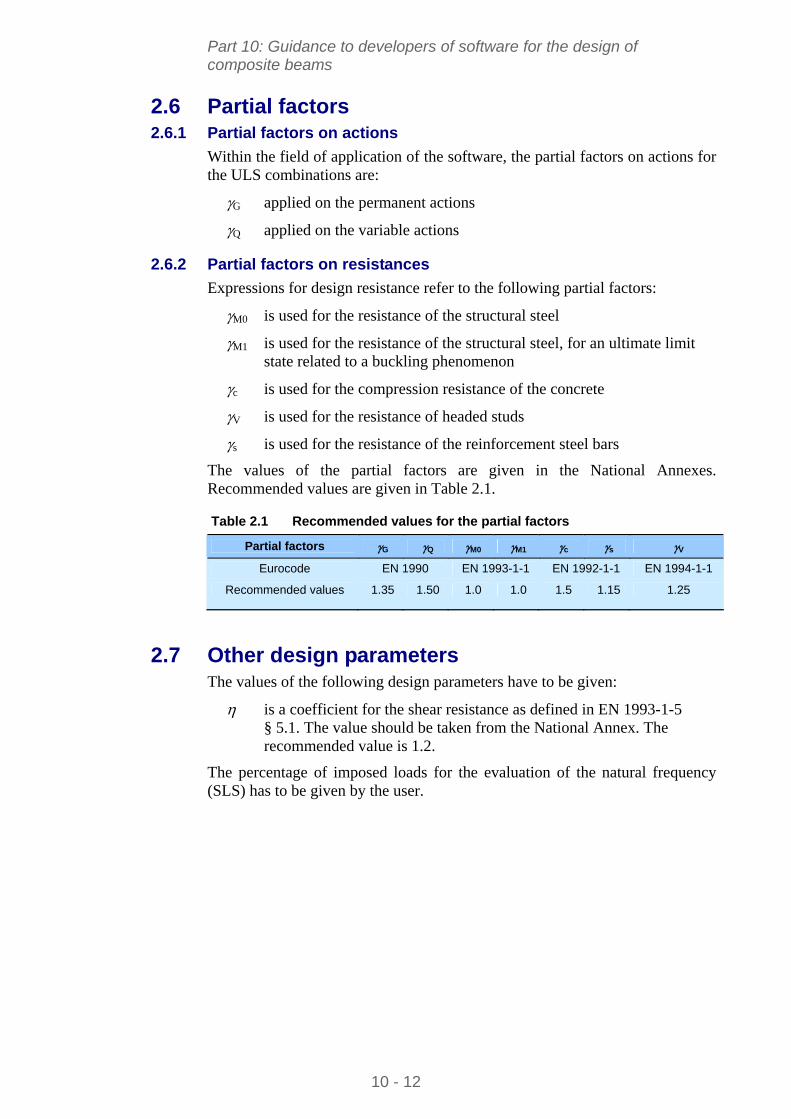
Part 10: Guidance to developers of software for the design of composite beams
2.6 Partial factors 2.6.1 Partial factors on actions
Within the field of application of the software, the partial factors on actions for the ULS combinations are:
G applied on the permanent actions
Q applied on the variable actions
2.6.2 Partial factors on resistances
Expressions for design resistance refer to the following partial factors:
M0 is used for the resistance of the structural steel
M1 is used for the resistance of the structural steel, for an ultimate limit state related to a buckling phenomenon
c is used for the compression resistance of the concrete
V is used for the resistance of headed studs
s is used for the resistance of the reinforcement steel bars
The values of the partial factors are given in the National Annexes. Recommended values are given in Table 2.1.
Table 2.1 Recommended values for the partial factors
Partial factors G Q M0 M1 c s V
Eurocode EN 1990 EN 1993-1-1 EN 1992-1-1 EN 1994-1-1
Recommended values 1.35 1.50 1.0 1.0 1.5 1.15 1.25
2.7 Other design parameters The values of the following design parameters have to be given:
is a coefficient for the shear resistance as defined in EN 1993-1-5 § 5.1. The value should be taken from the National Annex. The recommended value is 1.2.
The percentage of imposed loads for the evaluation of the natural frequency (SLS) has to be given by the user.
10 - 12
Part 10: Guidance to developers of software for the design of composite beams
3 MATERIAL PROPERTIES
3.1 Structural steel The steel properties are defined by EN 1993-1-1[3]:
E is the modulus of elasticity (E = 210000 N/mm2)
G is the shear modulus (G = 80770 N/mm2)
fy is the yield strength that is derived from Table 3.1 of EN 1993-1-1, depending on the steel grade and the material thickness. For simplicity, the yield strength may be derived from the flange thickness.
fyw is the yield strength of the web, derived from the web thickness.
is the material parameter defined as:
y/235 f
fy is the yield strength in N/mm2.
3.2 Reinforcement steel bars The properties of reinforcing steel are defined by EN 1992-1-1:
fyr,k is the yield strength of the transverse reinforcement bars.
3.3 Concrete The concrete properties are defined by EN 1992-1-1[4]. They are derived from the concrete class.
fck is the characteristic compressive strength at 28 days, as given in Table 3.1 of EN 1992-1-1.
fcd is the design compressive strength (EN 1994-1-1 § 2.4.1.2(2)):
fcd = fck / c
Ecm is the secant modulus of elasticity, as given in Table 3.1 of EN 1992-1-1.
10 - 13
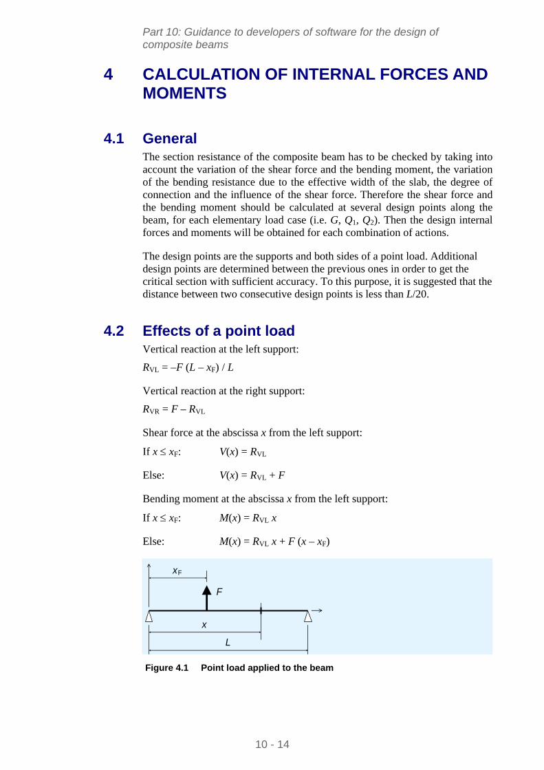
Part 10: Guidance to developers of software for the design of composite beams
4 CALCULATION OF INTERNAL FORCES AND MOMENTS
4.1 General The section resistance of the composite beam has to be checked by taking into account the variation of the shear force and the bending moment, the variation of the bending resistance due to the effective width of the slab, the degree of connection and the influence of the shear force. Therefore the shear force and the bending moment should be calculated at several design points along the beam, for each elementary load case (i.e. G, Q1, Q2). Then the design internal forces and moments will be obtained for each combination of actions.
The design points are the supports and both sides of a point load. Additional design points are determined between the previous ones in order to get the critical section with sufficient accuracy. To this purpose, it is suggested that the distance between two consecutive design points is less than L/20.
4.2 Effects of a point load Vertical reaction at the left support:
RVL = –F (L – xF) / L
Vertical reaction at the right support:
RVR = F – RVL
Shear force at the abscissa x from the left support:
If x xF: V(x) = RVL
Else: V(x) = RVL + F
Bending moment at the abscissa x from the left support:
If x xF: M(x) = RVL x
Else: M(x) = RVL x + F (x – xF)
F
xF
x
L
Figure 4.1 Point load applied to the beam
10 - 14
Part 10: Guidance to developers of software for the design of composite beams
4.3 Effects of a uniformly distributed surface load Vertical reaction at supports:
RVL = RVR = –Q (BL + BR) L / 4
Shear force at the abscissa x from the left support:
V(x) = RVL + Q (BL + BR) x / 2
Bending moment at the abscissa x from the left support:
M(x) = RVL x + Q (BL + BR) x2 /4
4.4 Combinations of actions 4.4.1 Ultimate Limit States (ULS)
The combinations of actions for the ULS verifications are the fundamental combinations as defined in EN 1990 § 6.4.3.2:
G G + Q Q1 + Q 0,2 Q2 G G + Q Q2 + Q 0,1 Q1
4.4.2 Serviceability Limit States (SLS)
The combinations of actions for the SLS verifications (deflection, vibration) can be either the characteristic or the frequent combinations, depending on the National Annex:
Characteristic combinations (EN 1990 § 6.5.3 a):
G + Q1 + 0,2 Q2 G + Q2 + 0,1 Q1
Frequent combinations (EN 1990 § 6.5.3 b):
G + 1,1 Q1 + 2,2 Q2 G + 1,2 Q2 + 2,1 Q1
10 - 15
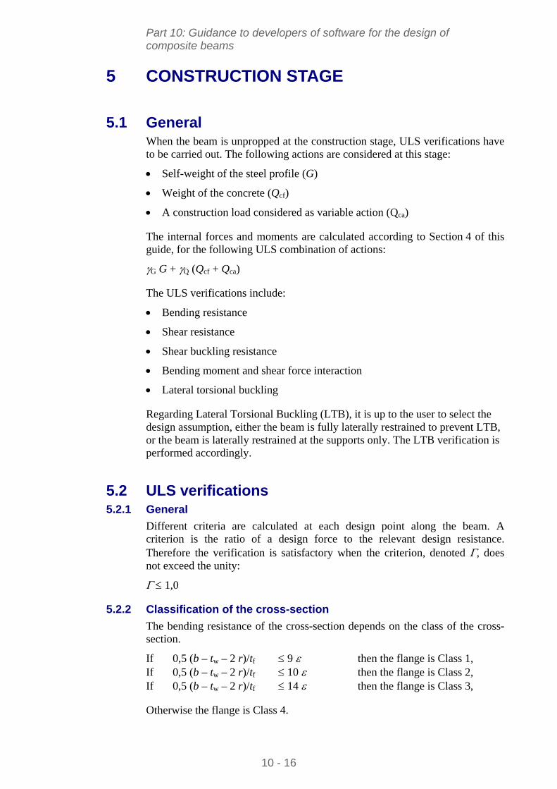
Part 10: Guidance to developers of software for the design of composite beams
5 CONSTRUCTION STAGE
5.1 General When the beam is unpropped at the construction stage, ULS verifications have to be carried out. The following actions are considered at this stage:
Self-weight of the steel profile (G)
Weight of the concrete (Qcf)
A construction load considered as variable action (Qca)
The internal forces and moments are calculated according to Section 4 of this guide, for the following ULS combination of actions:
G G + Q (Qcf + Qca)
The ULS verifications include:
Bending resistance
Shear resistance
Shear buckling resistance
Bending moment and shear force interaction
Lateral torsional buckling
Regarding Lateral Torsional Buckling (LTB), it is up to the user to select the design assumption, either the beam is fully laterally restrained to prevent LTB, or the beam is laterally restrained at the supports only. The LTB verification is performed accordingly.
5.2 ULS verifications 5.2.1 General
Different criteria are calculated at each design point along the beam. A criterion is the ratio of a design force to the relevant design resistance. Therefore the verification is satisfactory when the criterion, denoted , does not exceed the unity:
1,0
5.2.2 Classification of the cross-section
The bending resistance of the cross-section depends on the class of the cross-section.
If 0,5 (b – tw – 2 r)/tf 9 then the flange is Class 1, If 0,5 (b – tw – 2 r)/tf 10 then the flange is Class 2, If 0,5 (b – tw – 2 r)/tf 14 then the flange is Class 3,
Otherwise the flange is Class 4.
10 - 16
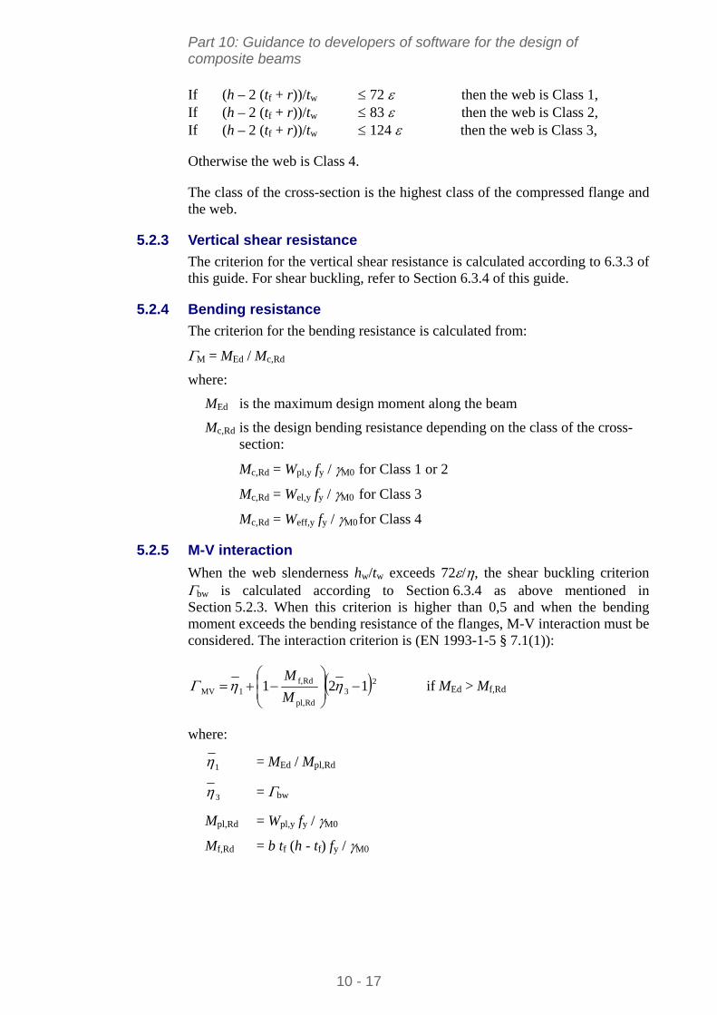
Part 10: Guidance to developers of software for the design of composite beams
If (h – 2 (tf + r))/tw 72 then the web is Class 1, If (h – 2 (tf + r))/tw 83 then the web is Class 2, If (h – 2 (tf + r))/tw 124 then the web is Class 3,
Otherwise the web is Class 4.
The class of the cross-section is the highest class of the compressed flange and the web.
5.2.3 Vertical shear resistance
The criterion for the vertical shear resistance is calculated according to 6.3.3 of this guide. For shear buckling, refer to Section 6.3.4 of this guide.
5.2.4 Bending resistance
The criterion for the bending resistance is calculated from:
M = MEd / Mc,Rd
where:
MEd is the maximum design moment along the beam
Mc,Rd is the design bending resistance depending on the class of the cross-section:
Mc,Rd = Wpl,y fy / M0 for Class 1 or 2
Mc,Rd = Wel,y fy / M0 for Class 3
Mc,Rd = Weff,y fy / M0 for Class 4
5.2.5 M-V interaction
When the web slenderness hw/tw exceeds 72/, the shear buckling criterion bw is calculated according to Section 6.3.4 as above mentioned in Section 5.2.3. When this criterion is higher than 0,5 and when the bending moment exceeds the bending resistance of the flanges, M-V interaction must be considered. The interaction criterion is (EN 1993-1-5 § 7.1(1)):
23
Rdpl,
Rdf,1MV 121
M
M if MEd > Mf,Rd
where:
= MEd / Mpl,Rd 1
3 = bw
Mpl,Rd = Wpl,y fy / M0
Mf,Rd = b tf (h - tf) fy / M0
10 - 17
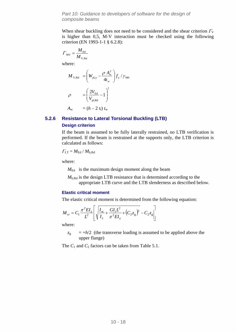
Part 10: Guidance to developers of software for the design of composite beams
When shear buckling does not need to be considered and the shear criterion V is higher than 0,5, M-V interaction must be checked using the following criterion (EN 1993-1-1 § 6.2.8):
RdV,
EdMV M
M
where:
M0yw
2
ypl,RdV, / 4
f
t
AWM w
2
Rdpl,
Ed 12
V
V
Aw = (h – 2 tf) tw
5.2.6 Resistance to Lateral Torsional Buckling (LTB)
Design criterion
If the beam is assumed to be fully laterally restrained, no LTB verification is performed. If the beam is restrained at the supports only, the LTB criterion is calculated as follows:
LT = MEd / Mb,Rd
where:
MEd is the maximum design moment along the beam
Mb,Rd is the design LTB resistance that is determined according to the appropriate LTB curve and the LTB slenderness as described below.
Elastic critical moment
The elastic critical moment is determined from the following equation:
g2
2g2
z2
2t
z
w2
z2
1cr zCzCEI
LGI
I
I
L
EICM
where:
zg = +h/2 (the transverse loading is assumed to be applied above the upper flange)
The C1 and C2 factors can be taken from Table 5.1.
10 - 18
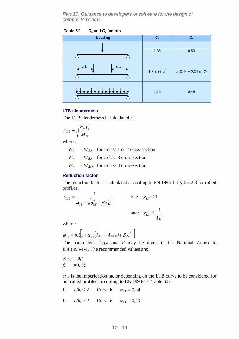
Part 10: Guidance to developers of software for the design of composite beams
Table 5.1 C1 and C2 factors
Loading C1 C2
1,35 0,59
L L 1 + 2,92 3 (2,44 – 3,24 ) C1
1,13 0,45
LTB slenderness
The LTB slenderness is calculated as:
cr
yyLT
M
fW
where:
Wy = Wpl,y for a class 1 or 2 cross-section
Wy = Wel,y for a class 3 cross-section
Wy = Weff,y for a class 4 cross-section
Reduction factor
The reduction factor is calculated according to EN 1993-1-1 § 6.3.2.3 for rolled profiles:
2LT
2LTLT
LT1
but: 1LT
and: 2LT
LT1
where:
2LTLT,0LTLTLT 15,0
LT,0The parameters and may be given in the National Annex to EN 1993-1-1. The recommended values are:
4,0LT,0
= 0,75
LT is the imperfection factor depending on the LTB curve to be considered for hot rolled profiles, according to EN 1993-1-1 Table 6.5:
If h/bf 2 Curve b LT = 0,34
If h/bf > 2 Curve c LT = 0,49
10 - 19
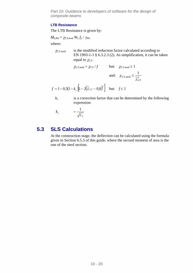
Part 10: Guidance to developers of software for the design of composite beams
LTB Resistance
The LTB Resistance is given by:
Mb,Rd = LT,mod Wy fy / M1
where:
LT,mod is the modified reduction factor calculated according to EN 1993-1-1 § 6.3.2.3 (2). As simplification, it can be taken equal to LT.
LT,mod = LT / f but: LT,mod 1
and: 2LT
modLT,1
2LTc 8,02115,01 kf but: f 1
kc is a correction factor that can be determined by the following expression:
1
c
1
Ck
5.3 SLS Calculations At the construction stage, the deflection can be calculated using the formula given in Section 6.5.3 of this guide, where the second moment of area is the one of the steel section.
10 - 20
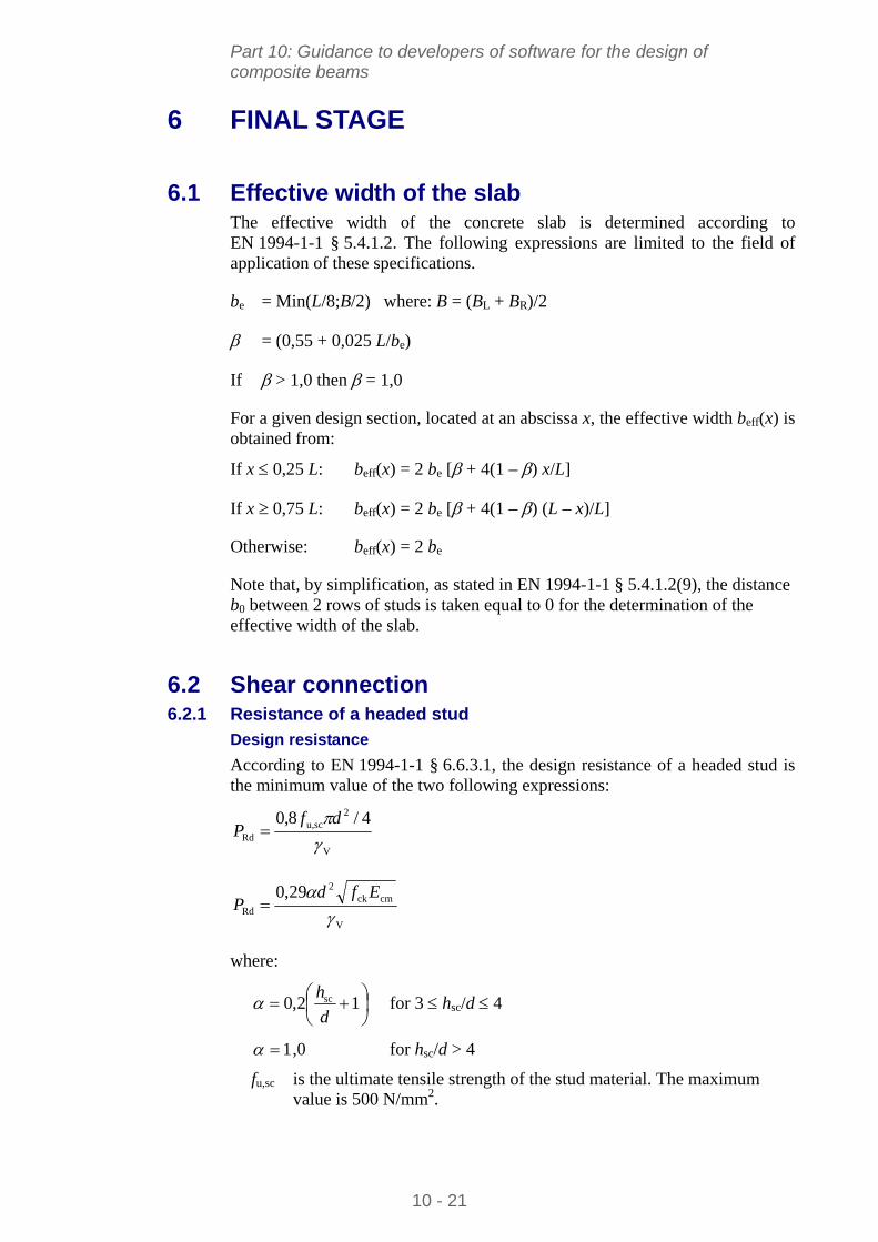
Part 10: Guidance to developers of software for the design of composite beams
6 FINAL STAGE
6.1 Effective width of the slab The effective width of the concrete slab is determined according to EN 1994-1-1 § 5.4.1.2. The following expressions are limited to the field of application of these specifications.
be = Min(L/8;B/2) where: B = (BL + BR)/2
= (0,55 + 0,025 L/be)
If > 1,0 then = 1,0
For a given design section, located at an abscissa x, the effective width beff(x) is obtained from:
If x 0,25 L: beff(x) = 2 be [ + 4(1 – ) x/L]
If x 0,75 L: beff(x) = 2 be [ + 4(1 – ) (L – x)/L]
Otherwise: beff(x) = 2 be
Note that, by simplification, as stated in EN 1994-1-1 § 5.4.1.2(9), the distance b0 between 2 rows of studs is taken equal to 0 for the determination of the effective width of the slab.
6.2 Shear connection 6.2.1 Resistance of a headed stud
Design resistance
According to EN 1994-1-1 § 6.6.3.1, the design resistance of a headed stud is the minimum value of the two following expressions:
V
2scu,
Rd
4/8,0
df
P
V
cmck2
Rd
29,0
Efd
P
where:
12,0 sc
d
h for 3 hsc/d 4
,0 for hsc/d > 4 1
fu,sc is the ultimate tensile strength of the stud material. The maximum value is 500 N/mm2.
10 - 21
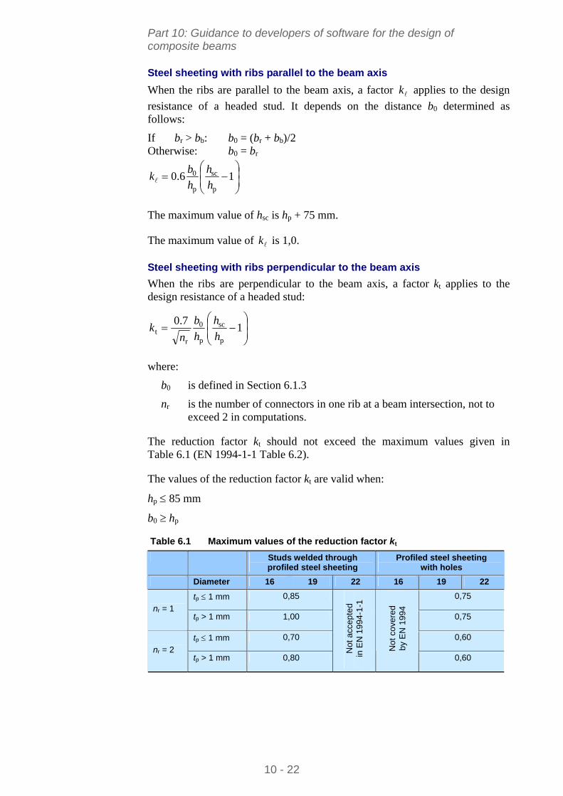
Part 10: Guidance to developers of software for the design of composite beams
Steel sheeting with ribs parallel to the beam axis
When the ribs are parallel to the beam axis, a factor applies to the design
resistance of a headed stud. It depends on the distance b0 determined as follows:
k
If br > bb: b0 = (br + bb)/2 Otherwise: b0 = br
16.0
p
sc
p
0
h
h
h
bk
The maximum value of hsc is hp + 75 mm.
The maximum value of is 1,0. k
Steel sheeting with ribs perpendicular to the beam axis
When the ribs are perpendicular to the beam axis, a factor kt applies to the design resistance of a headed stud:
1
7.0
p
sc
p
0
rt h
h
h
b
nk
where:
b0 is defined in Section 6.1.3
nr is the number of connectors in one rib at a beam intersection, not to exceed 2 in computations.
The reduction factor kt should not exceed the maximum values given in Table 6.1 (EN 1994-1-1 Table 6.2).
The values of the reduction factor kt are valid when:
hp 85 mm
b0 hp
Table 6.1 Maximum values of the reduction factor kt
Studs welded through Profiled steel sheeting profiled steel sheeting with holes
Diameter 16 19 22 16 19 22
tp 1 mm 0,85 0,75
nr = 1 tp > 1 mm 1,00 0,75
tp 1 mm 0,70 0,60
nr = 2 tp > 1 mm 0,80
Not
acc
epte
d in
EN
19
94-1
-1
Not
cov
ered
by
EN
199
4
0,60
10 - 22
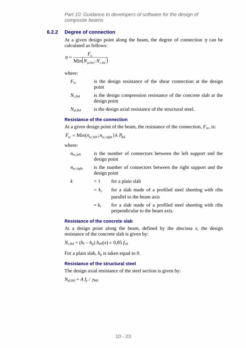
Part 10: Guidance to developers of software for the design of composite beams
6.2.2 Degree of connection
At a given design point along the beam, the degree of connection can be calculated as follows:
Rdc,Rdpl,
sc
;Min NN
F
where:
Fsc is the design resistance of the shear connection at the design point
Nc,Rd is the design compression resistance of the concrete slab at the design point
Npl,Rd is the design axial resistance of the structural steel.
Resistance of the connection
At a given design point of the beam, the resistance of the connection, Fsc, is:
Rdrightsc,leftsc,sc );(Min PknnF
where:
nsc,left is the number of connectors between the left support and the design point
nsc,right is the number of connectors between the right support and the design point
k = 1 for a plain slab
= for a slab made of a profiled steel sheeting with ribs
parallel to the beam axis k
= kt for a slab made of a profiled steel sheeting with ribs perpendicular to the beam axis.
Resistance of the concrete slab
At a design point along the beam, defined by the abscissa x, the design resistance of the concrete slab is given by:
Nc,Rd = (hf – hp) beff(x) 0,85 fcd
For a plain slab, hp is taken equal to 0.
Resistance of the structural steel
The design axial resistance of the steel section is given by:
Npl,Rd = A fy / M0
10 - 23
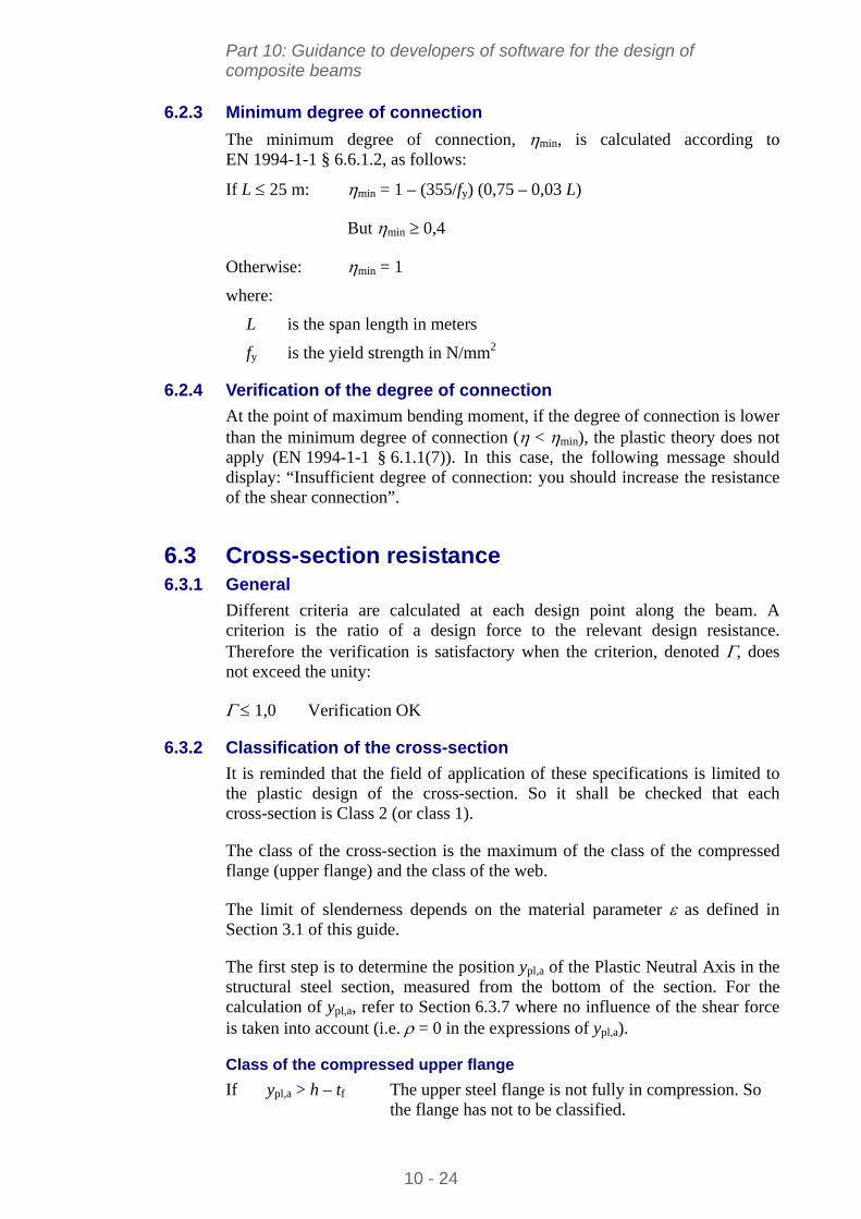
Part 10: Guidance to developers of software for the design of composite beams
6.2.3 Minimum degree of connection
The minimum degree of connection, min, is calculated according to EN 1994-1-1 § 6.6.1.2, as follows:
If L 25 m: min = 1 – (355/fy) (0,75 – 0,03 L)
But min 0,4
Otherwise: min = 1
where:
L is the span length in meters
fy is the yield strength in N/mm2
6.2.4 Verification of the degree of connection
At the point of maximum bending moment, if the degree of connection is lower than the minimum degree of connection ( < min), the plastic theory does not apply (EN 1994-1-1 § 6.1.1(7)). In this case, the following message should display: “Insufficient degree of connection: you should increase the resistance of the shear connection”.
6.3 Cross-section resistance 6.3.1 General
Different criteria are calculated at each design point along the beam. A criterion is the ratio of a design force to the relevant design resistance. Therefore the verification is satisfactory when the criterion, denoted , does not exceed the unity:
1,0 Verification OK
6.3.2 Classification of the cross-section
It is reminded that the field of application of these specifications is limited to the plastic design of the cross-section. So it shall be checked that each cross-section is Class 2 (or class 1).
The class of the cross-section is the maximum of the class of the compressed flange (upper flange) and the class of the web.
The limit of slenderness depends on the material parameter as defined in Section 3.1 of this guide.
The first step is to determine the position ypl,a of the Plastic Neutral Axis in the structural steel section, measured from the bottom of the section. For the calculation of ypl,a, refer to Section 6.3.7 where no influence of the shear force is taken into account (i.e. = 0 in the expressions of ypl,a).
Class of the compressed upper flange
If ypl,a > h – tf The upper steel flange is not fully in compression. So the flange has not to be classified.
10 - 24
Part 10: Guidance to developers of software for the design of composite beams
For the classification, the flange slenderness is: f = 0,5 (b – tw – 2 r)/tf
If f 10 The flange is class 2 (or 1) (EN 1993-1-1 Table 5.2).
When f > 10 , the following requirements shall be fulfilled to conclude that the flange is Class 2 (EN 1994-1-1 § 5.5.2(1) and § 6.6.5.5):
For plain slabs or slabs with profiled steel sheeting parallel to the beam axis, the longitudinal spacing between the connectors is lower than 22 tf.
For slabs with profiled steel sheeting perpendicular to the beam axis, the longitudinal spacing between the connectors is lower than 15 tf.
The longitudinal spacing between the connectors is lower than 6 times the slab depth (6 hf).
The longitudinal spacing between the connectors is lower than 800 mm.
The clear distance from the edge of the flange to the nearest line of connectors is not greater than 9 tf.
Class of the web
If ypl,a > h – tf – r The web is fully in tension. So the web has not to classified.
For the classification, the flange slenderness is: w = (h – 2tf – 2r)/tw
The compression part of the web is estimated by the ratio:
rth
yrth
22 f
apl,f
Here the ratio is supposed to be lower than 0,5.
113
456
If w The web is class 2 (or 1).
6.3.3 Vertical shear resistance
The vertical shear resistance of a cross-section is calculated according to EN 1993-1-1 § 6.2.6. The contribution of the concrete slab is neglected.
M0
yzv,Rdpl,
3fA
V
The criterion is calculated by:
Rdpl,
EdV V
V
10 - 25
Part 10: Guidance to developers of software for the design of composite beams
6.3.4 Shear buckling resistance
When the web slenderness hw/tw exceeds 72/, the shear buckling resistance Vbw,Rd has to be calculated according to EN 1993-1-5 § 5.2, with the following assumptions:
Only the contribution of the web is considered
The end posts are non rigid
Therefore the design resistance for shear buckling is obtained from:
M1
ywwwwRdbw,
3 fth
V
where:
hw is the height of the web: hw = h – 2 tf
w is the reduction factor for shear buckling that depends on the web
slenderness w
The web slenderness is:
kt
h
ww
ww
4,37
where:
yww /235 f
k = 5,34
The reduction factor w is calculated as follows:
w < 0,83/: w = If
wOtherwise w = 0,83/
Then the criterion is calculated by:
Rdbw,
EdVb V
V
6.3.5 Bending resistance
The bending resistance MRd of a cross-section is calculated according to 6.3.7, by taking the parameter equal to 0 (i.e. no influence of the shear force). The criterion is obtained from:
Rd
EdM M
M
10 - 26
Part 10: Guidance to developers of software for the design of composite beams
6.3.6 M-V interaction
When the web slenderness hw/tw exceeds 72/, the shear buckling criterion bw is calculated according to 6.3.4. When this criterion is higher than 0,5, M-V interaction shall be considered. The interaction criterion is:
RdV,
EdMV M
M
The bending resistance MV,Rd is calculated according to 6.3.7 with the parameter obtained from:
2
Rdbw,
Ed 12
V
V
When shear buckling has not to be considered, Vbw,Rd is replaced by Vpl,Rd. If the shear criterion V is higher than 0,5, interaction must be considered and MV,Rd is calculated according to 6.3.7 with the parameter obtained from:
2
Rdpl,
Ed 12
V
V
6.3.7 General expression of the bending resistance
The following procedure allows the user to calculate the design bending resistance, including the reduction due to the shear force. When the effect of the shear force can be neglected, the parameter is taken equal to 0. The plastic stress distribution is shown in Figure 6.1.
ypl,c
ypl,a
beff(x)
+0,85 fcd
+fy / M0
-fy / M0
+(1-)fy / M0
-(1-)fy / M0
Figure 6.1 Plastic stress distribution with partial connection
10 - 27
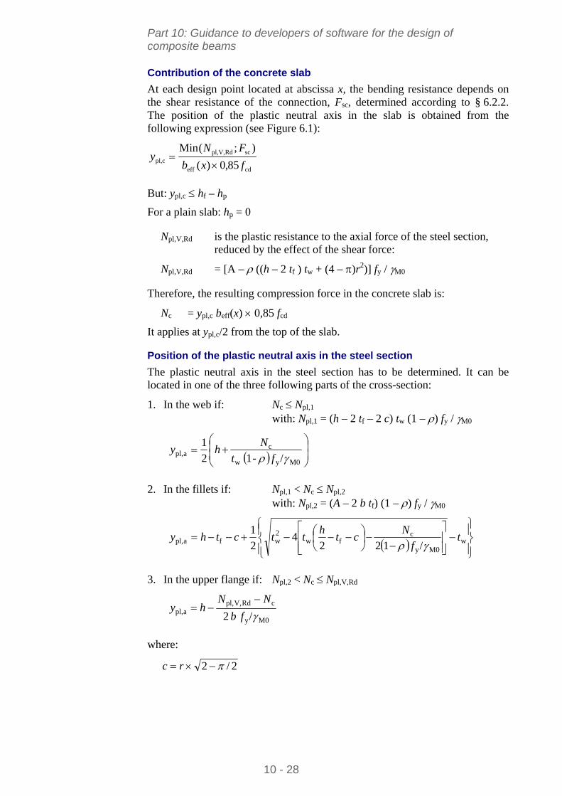
Part 10: Guidance to developers of software for the design of composite beams
Contribution of the concrete slab
At each design point located at abscissa x, the bending resistance depends on the shear resistance of the connection, Fsc, determined according to § 6.2.2. The position of the plastic neutral axis in the slab is obtained from the following expression (see Figure 6.1):
cdeff
scRdV,pl,cpl, 85,0)(
);(Min
fxb
FNy
But: ypl,c hf – hp
For a plain slab: hp = 0
Npl,V,Rd is the plastic resistance to the axial force of the steel section, reduced by the effect of the shear force:
Npl,V,Rd = [A – ((h – 2 tf ) tw + (4 – )r2)] fy / M0
Therefore, the resulting compression force in the concrete slab is:
Nc = ypl,c beff(x) 0,85 fcd
It applies at ypl,c/2 from the top of the slab.
Position of the plastic neutral axis in the steel section
The plastic neutral axis in the steel section has to be determined. It can be located in one of the three following parts of the cross-section:
1. In the web if: Nc Npl,1
with: Npl,1 = (h – 2 tf – 2 c) tw (1 – ) fy / M0
M0yw
capl, / -1 2
1
ft
Nhy
2. In the fillets if: Npl,1 < Nc Npl,2
with: Npl,2 = (A – 2 b tf) (1 – ) fy / M0
w
M0y
cfw
2wfapl, /122
42
1t
f
Nct
httcthy
3. In the upper flange if: Npl,2 < Nc Npl,V,Rd
M0y
cRdV,pl,apl, / 2 fb
NNhy
where:
2/2 rc
10 - 28
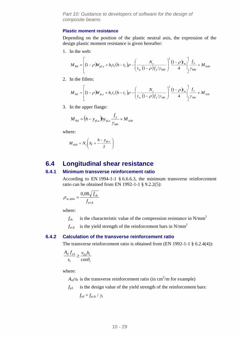
Part 10: Guidance to developers of software for the design of composite beams
Plastic moment resistance
Depending on the position of the plastic neutral axis, the expression of the design plastic moment resistance is given hereafter:
1. In the web:
slabM0
yw
2
M0yw
cfffypl,Rd 4
1
/1 1 M
ft
ft
NthtbWM
2. In the fillets:
slabM0
yw
2
M0yw
cfffypl,Rd 4
1
/1 1 M
ft
ft
NthtbWM
3. In the upper flange:
slabM0
yapl,apl,Rd M
fbyyhM
where:
2cpl,
fcslab
yhhNM
6.4 Longitudinal shear resistance 6.4.1 Minimum transverse reinforcement ratio
According to EN 1994-1-1 § 6.6.6.3, the minimum transverse reinforcement ratio can be obtained from EN 1992-1-1 § 9.2.2(5):
kyr,
ckminw,
0,08
f
f
where:
fck is the characteristic value of the compression resistance in N/mm2
fyr,k is the yield strength of the reinforcement bars in N/mm2
6.4.2 Calculation of the transverse reinforcement ratio
The transverse reinforcement ratio is obtained from (EN 1992-1-1 § 6.2.4(4)):
f
fEd
f
ydsf
cothv
s
fA
where:
Asf/sf is the transverse reinforcement ratio (in cm2/m for example)
fyd is the design value of the yield strength of the reinforcement bars:
fyd = fyr,k / s
10 - 29
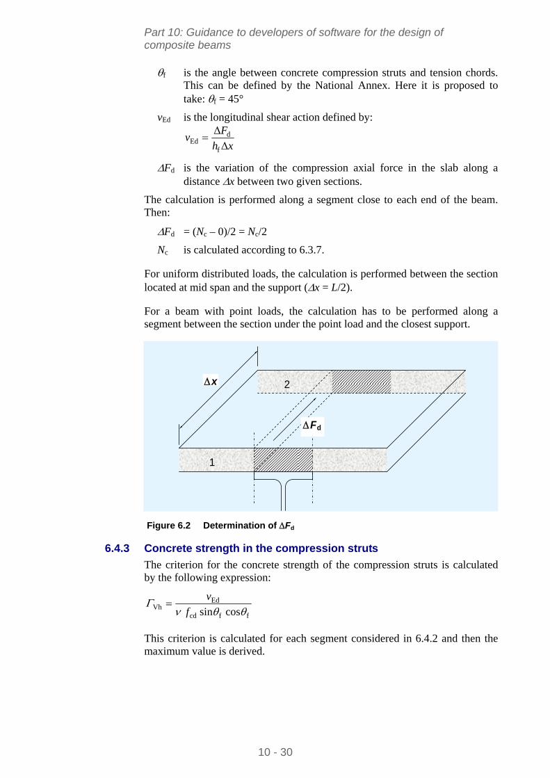
Part 10: Guidance to developers of software for the design of composite beams
f is the angle between concrete compression struts and tension chords. This can be defined by the National Annex. Here it is proposed to take: f = 45°
vEd is the longitudinal shear action defined by:
xh
Fv
Δ
Δ
f
dEd
Fd is the variation of the compression axial force in the slab along a distance x between two given sections.
The calculation is performed along a segment close to each end of the beam. Then:
Fd = (Nc – 0)/2 = Nc/2
Nc is calculated according to 6.3.7.
For uniform distributed loads, the calculation is performed between the section located at mid span and the support (x = L/2).
For a beam with point loads, the calculation has to be performed along a segment between the section under the point load and the closest support.
Fd
1
2x
Figure 6.2 Determination of Fd
6.4.3 Concrete strength in the compression struts
The criterion for the concrete strength of the compression struts is calculated by the following expression:
ffcd
EdVh cos sin
f
v
This criterion is calculated for each segment considered in 6.4.2 and then the maximum value is derived.
10 - 30
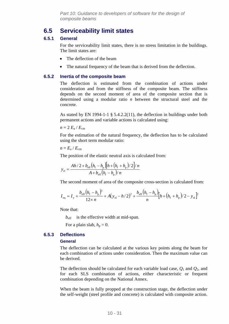
Part 10: Guidance to developers of software for the design of composite beams
6.5 Serviceability limit states 6.5.1 General
For the serviceability limit states, there is no stress limitation in the buildings. The limit states are:
The deflection of the beam
The natural frequency of the beam that is derived from the deflection.
6.5.2 Inertia of the composite beam
The deflection is estimated from the combination of actions under consideration and from the stiffness of the composite beam. The stiffness depends on the second moment of area of the composite section that is determined using a modular ratio n between the structural steel and the concrete.
As stated by EN 1994-1-1 § 5.4.2.2(11), the deflection in buildings under both permanent actions and variable actions is calculated using:
n = 2 Ea / Ecm
For the estimation of the natural frequency, the deflection has to be calculated using the short term modular ratio:
n = Ea / Ecm
The position of the elastic neutral axis is calculated from:
nhhbA
nhhhhhbAhy
/
/2/2/
pfeff
pfpfeffel
The second moment of area of the composite cross-section is calculated from:
2elpfpfeff2
el
3pfeff
yeq 2/2/12
yhhhn
hhbhyA
n
hhbII
Note that:
beff is the effective width at mid-span.
For a plain slab, hp = 0.
6.5.3 Deflections
General
The deflection can be calculated at the various key points along the beam for each combination of actions under consideration. Then the maximum value can be derived.
The deflection should be calculated for each variable load case, Q1 and Q2, and for each SLS combination of actions, either characteristic or frequent combination depending on the National Annex.
When the beam is fully propped at the construction stage, the deflection under the self-weight (steel profile and concrete) is calculated with composite action.
10 - 31
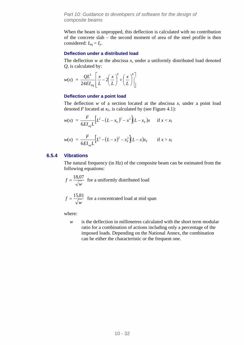
Part 10: Guidance to developers of software for the design of composite beams
When the beam is unpropped, this deflection is calculated with no contribution of the concrete slab – the second moment of area of the steel profile is then considered: I = I .
the abscissa x, under a uniformly distributed load denoted Q, is calculated by:
w(x) =
eq y
Deflection under a distributed load
The deflection w at
43
eq
3
224 L
x
L
x
L
x
EI
QL
Deflection under a point load
The deflection w of a section located at the abscissa x, under a point load denoted F located at xF, is calculated by (see Figure 4.1):
w(x) = xxLxxLLLEI
FF
22F
2
eq6 if x < xf
w(x) = F2F
22
eq6xxLxxLL
LEI
F if x > xf
6.5.4
(in Hz) of the composite beam can be estimated from the following equations:
Vibrations
The natural frequency
wf
07,18 for a uniformly distributed load
wf
81,15 for a concentrated load at mid span
where:
w
he combination can be either the characteristic or the frequent one.
is the deflection in millimetres calculated with the short term modularratio for a combination of actions including only a percentage of the imposed loads. Depending on the National Annex, t
10 - 32
Part 10: Guidance to developers of software for the design of composite beams
7 LIST OF THE MAIN OUTPUTS
The following list is a summary of the main results of the calculations:
At the construction stage:
The maximum bending moment and its location along the beam
The maximum criterion for the bending resistance (M,max)
The maximum vertical shear force and its location along the beam
The maximum criterion for the vertical shear resistance (V,max)
The maximum criterion for the shear buckling resistance, when necessary (Vb,max)
The criterion for the LTB resistance (LT)
The maximum deflection under self-weight of the beam and under the weight of the concrete
The maximum deflection under the construction loads.
At the final stage:
The effective width of the concrete slab
The shear resistance of headed studs
The maximum bending moment and its location along the beam
The maximum vertical shear force and its location along the beam
The degree of connection
The minimum degree of connection
The maximum criterion for vertical shear resistance (V,max)
The maximum criterion for shear buckling resistance (Vb,max)
The maximum criterion for bending resistance (M,max)
The maximum criterion for bending resistance reduced by the influence of the vertical shear force (MV,max)
The maximum criterion for the resistance to the horizontal shear force in the concrete slab (Vh,max)
The transverse reinforcement ratio
The maximum deflection under each variable load case Q1 and Q2
The maximum deflection under each SLS combination
The natural frequency under each SLS combination.
10 - 33
Part 10: Guidance to developers of software for the design of composite beams
10 - 34
REFERENCES
1 EN 1994-1-1:2004 Eurocode 4 Design of composite steel and concrete structures. General rules and rules for buildings.
2 EN 1990:2002 Eurocode Basis of structural design.
3 EN 1993-1-1:2005 Eurocode 3 Design of steel structures. General rules and rules for buildings
4 EN 1992-1-1:2004 Eurocode 2: Design of concrete structures. General rules and rules for buildings.
Part 10: Guidance to developers of software for the design of composite beams
APPENDIX A Overall flowchart
Calculation of internal forces and moment at each DP for load case
Effective width of the slab
Degree of shear connection
Determination of Design Points (DP)
Minimum degree of shear connection
Start
beff(x)
Basic data
Position of DPs
M, V
min
min ? “Increase the degree of shear connection”
No
Yes
Cross-section resistance
Longitudinal shear resistance
Criteria M, V…
Design criterion Transverse reinf.
§ 6.1…
§ 4…
§ 6.2.2…
§ 6.2.3…
§ 6.3…
End
SLS Calculations Deflections Natural frequency
§ 6.4…
§ 6.5…
Calculations at the construction stage § 5… Flowchart A.2
§ 4.1…
Figure A.1 Overall flowchart of the calculations
10 - 35
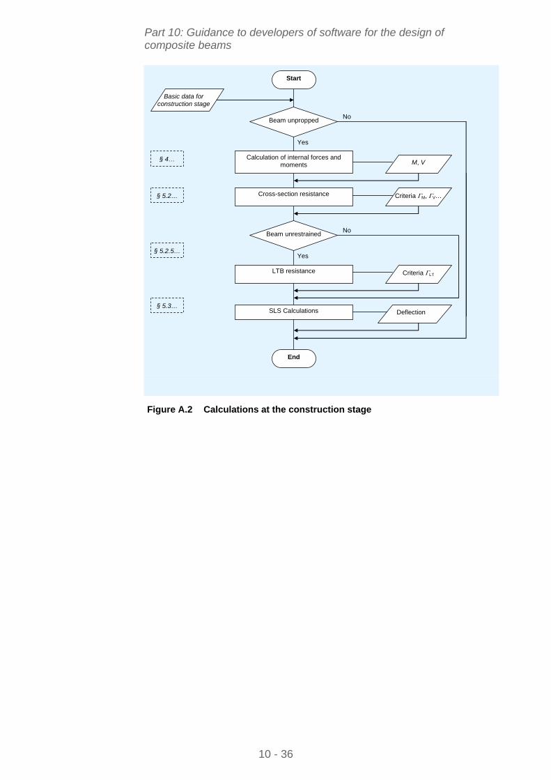
Part 10: Guidance to developers of software for the design of composite beams
10 - 36
No
Yes
No
Yes
Calculation of internal forces and moments
Start
Basic data for construction stage
M, V
Beam unpropped
Cross-section resistance Criteria M, V…
§ 4…
End
SLS Calculations Deflection
Beam unrestrained
LTB resistance Criteria LT
§ 5.2…
§ 5.2.5…
§ 5.3…
Figure A.2 Calculations at the construction stage
Top Related