


Languages
Pages
Legal

2
Agenda
1.Legacy NW Migrationの必要性と目的
2.Requirement
3.現状の問題点
4.Migration Scenarioの検討
5.Summary
3
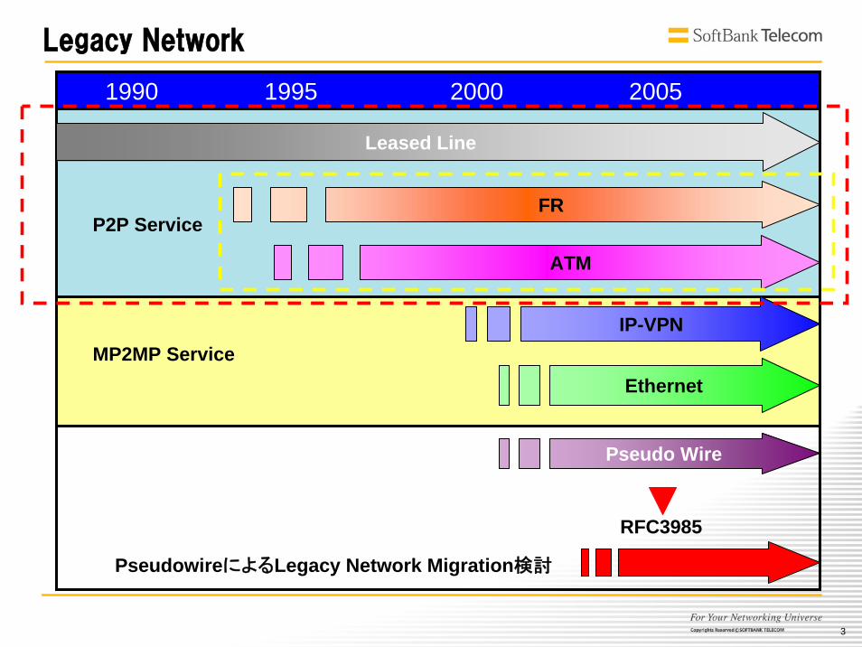
Legacy Network
1990 1995 2000 2005
Leased Line
FR
ATM
IP-VPN
Ethernet
Pseudo Wire
RFC3985
PseudowireによるLegacy Network Migration検討
P2P Service
MP2MP Service

4
現状のNetwork
ATMATM
FRFR
IPIP--VPNVPN
EthernetEthernet
専用線専用線
サービスが生まれるたびに全国NWを構築
5
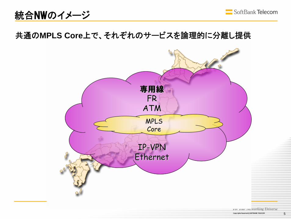
統合NWのイメージ
専用線専用線FRFR
ATMATM
IPIP--VPNVPNEthernetEthernet
MPLSMPLSCoreCore
共通のMPLS Core上で、それぞれのサービスを論理的に分離し提供
6
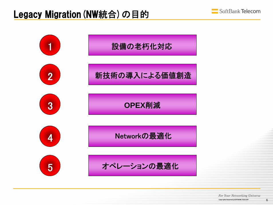
Legacy Migration(NW統合)の目的
5
4
3
2
1 設備の老朽化対応
OPEX削減
オペレーションの 適化
Networkの 適化
新技術の導入による価値創造
7
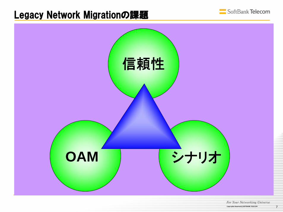
Legacy Network Migrationの課題
シナリオOAM
信頼性

8
1.Legacy NW Migrationの必要性と目的
2.Requirement
3.現状の問題点
4.Migration Scenarioの検討
5.Summary

9
信頼性
HW完全冗長
共通部モジュール冗長
LineCard冗長
1+1APS/MSPprotectionsub 50ms無瞬断upgrade
管理
パス管理
容量管理
QOS100% e-e帯域保証
Low Latency
OAMFull Rate試験
LoopDrop/InsertPerformance Monitoring
伝送(専用線)の世界って

10
ATMの世界って
管理
パス管理
容量管理
回線ごとのルート管理
QOSService Class(CBR/rtVBR/nrtVBR/UBR/UBR+/ABR/GFR…)帯域保証(100%保証、一部保証)Policing/ShapingCLPPCR/SCR/MCR/MBSCACOversubscription
信頼性
HW完全冗長
共通部モジュール冗長
LineCard冗長
1+1APS/MSPRerouting瞬断upgrade
OAM豊富なOAM
AIS/RDILoopbackCCPerformance Monitoring

11
FRの世界って
管理
パス管理
容量管理
回線ごとのルート管理
QOS帯域保証(CIR保証)PIR/CIRBc/BeDEOversubscription
信頼性
HW完全冗長
共通部モジュール冗長
LineCard冗長
Rerouting瞬断upgrade
OAMLMIActive bit/New bitFR/ATM Interwork
12
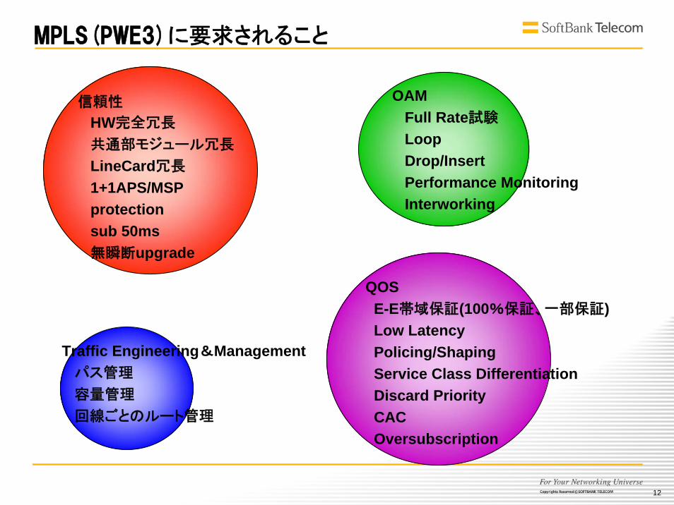
MPLS(PWE3)に要求されること
信頼性
HW完全冗長
共通部モジュール冗長
LineCard冗長
1+1APS/MSPprotectionsub 50ms無瞬断upgrade
Traffic Engineering&Managementパス管理
容量管理
回線ごとのルート管理
QOSE-E帯域保証(100%保証、一部保証)Low LatencyPolicing/ShapingService Class DifferentiationDiscard PriorityCACOversubscription
OAMFull Rate試験
LoopDrop/InsertPerformance MonitoringInterworking
13
1.Legacy NW Migrationの必要性と目的
2.Requirement
3.現状の問題点
4.Migration Scenarioの検討
5.Summary
14
信頼性
15
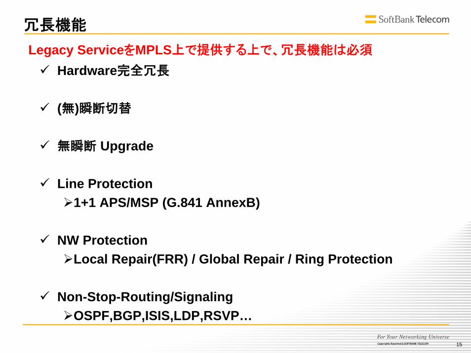
冗長機能
Hardware完全冗長
(無)瞬断切替
無瞬断 Upgrade
Line Protection1+1 APS/MSP (G.841 AnnexB)
NW ProtectionLocal Repair(FRR) / Global Repair / Ring Protection
Non-Stop-Routing/SignalingOSPF,BGP,ISIS,LDP,RSVP…
Legacy ServiceをMPLS上で提供する上で、冗長機能は必須

16
APS/MSPのいろいろ
通称 標準 特徴
ITU-TAnnexA
・ITU-T G.841 Section. 7.1 (1998/10)・(旧)ITU-T G.783 Annex A (1997/04)
MSP(Multiplex Section Protection)
勧告仕様的には、以下の選択が可能だが、
ベンダ、機器によって実装は異なる。
1+1/1:NBi-directional/Uni-directionalRevertive/Non-Revertive
K1/K2 byte W系: “0001”、P系: “0000”
SDH
SONET
TTCAnnexBNTT仕様
・ITU-T G.841 Annex B (1998/10)・TTC JT-G.783 (2001/04 第3版)・(旧)ITU-T G.783 Annex B (1997/04)
MSP(Multiplex Section Protection)
1+1、Bi-directional、Non-Revのみ。
Working/Protectionという物理実装位置による
機能の役割はなく、0系/1系という呼称で、状態に
よって機能の役割が変わる。
(例:「1系現用選択強制切替中」)
K1/K2 byte 0系: “0001”、1系: “0002”ITU-Tとは切替優先度が異なる。
SONETANSI
・ANSI T1.105.01 (2000)・[Telcordia GR-253-core (旧Bellcore)]
APS(Automatic Protection Switching)
1+1/1:NBi-directional/Uni-directionalRevertive/Non-Revertive
K1/K2 byte W系: “0001”、P系: “0000”ITU-Tとは切替優先度が異なる。
K2 Byte 6-8 ビットの定義がある
17
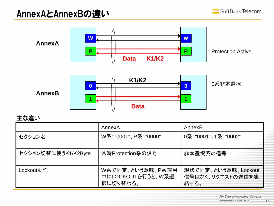
AnnexAとAnnexBの違い
AnnexA AnnexB
セクション名 W系: “0001”、P系: “0000” 0系: “0001”、1系: “0002”
セクション切替に使うK1/K2Byte 常時Protection系の信号 非本選択系の信号
Lockout動作 W系で固定、という意味。P系運用中にLOCKOUTを行うと、W系選
択に切り替わる。
現状で固定、という意味。Lockout信号はなく、リクエストの送信を凍結する。
主な違い
W
P
W
P
0
1
0
1
K1/K2
AnnexA
AnnexB
K1/K2
0系非本選択
Protection Active
Data
Data
18
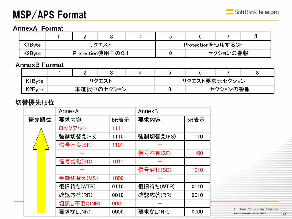
MSP/APS Format
AnnexA AnnexB
信号不良(SF) 1101 -
信号劣化(SD) 1011 -
優先順位 要求内容 bit表示 要求内容 bit表示
ロックアウト 1111 -
強制切替え(FS)
信号不良(SF)
信号劣化(SD)
-
復旧待ち(WTR)
確認応答(RR)
-
要求なし(NR)
強制切替え(FS) 1110 1110
- 1100
- 1010
手動切替え(MS) 1000
復旧待ち(WTR) 0110 0110
確認応答(RR) 0010 0010
切戻し不要(DNR) 0001
要求なし(NR) 0000 0000
セクションの警報0本選択中のセクションK2Byte
リクエスト要求元セクションリクエストK1Byte
87654321
セクションの警報0Protection使用中のCHK2Byte
Protectionを使用するCHリクエストK1Byte
87654321
AnnexA Format
AnnexB Format
切替優先順位
19
日本仕様の苦悩
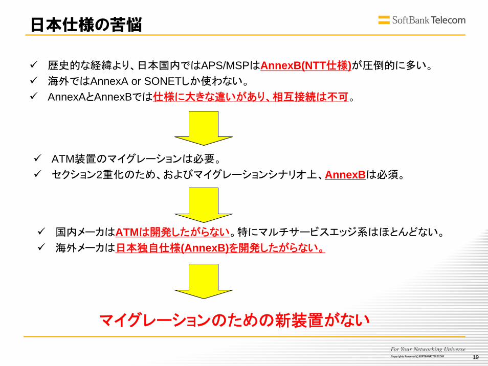
歴史的な経緯より、日本国内ではAPS/MSPはAnnexB(NTT仕様)が圧倒的に多い。
海外ではAnnexA or SONETしか使わない。
AnnexAとAnnexBでは仕様に大きな違いがあり、相互接続は不可。
国内メーカはATMは開発したがらない。特にマルチサービスエッジ系はほとんどない。
海外メーカは日本独自仕様(AnnexB)を開発したがらない。
ATM装置のマイグレーションは必要。
セクション2重化のため、およびマイグレーションシナリオ上、AnnexBは必須。
マイグレーションのための新装置がない
20
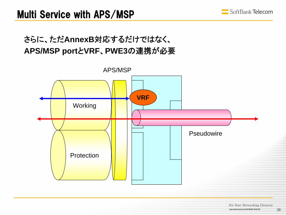
Working
Protection
Multi Service with APS/MSP
VRF
Pseudowire
APS/MSP
さらに、ただAnnexB対応するだけではなく、
APS/MSP portとVRF、PWE3の連携が必要
21
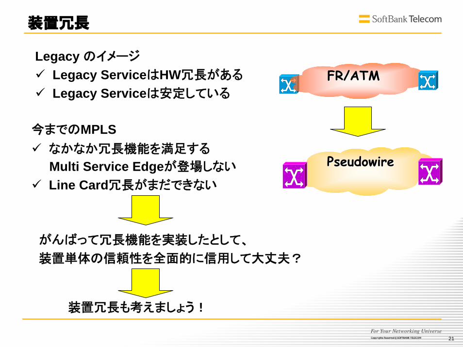
装置冗長
今までのMPLSなかなか冗長機能を満足する
Multi Service Edgeが登場しない
Line Card冗長がまだできない
装置冗長も考えましょう!
Legacy のイメージ
Legacy ServiceはHW冗長がある
Legacy Serviceは安定している
FR/ATMFR/ATM
PseudowirePseudowire
がんばって冗長機能を実装したとして、
装置単体の信頼性を全面的に信用して大丈夫?
22
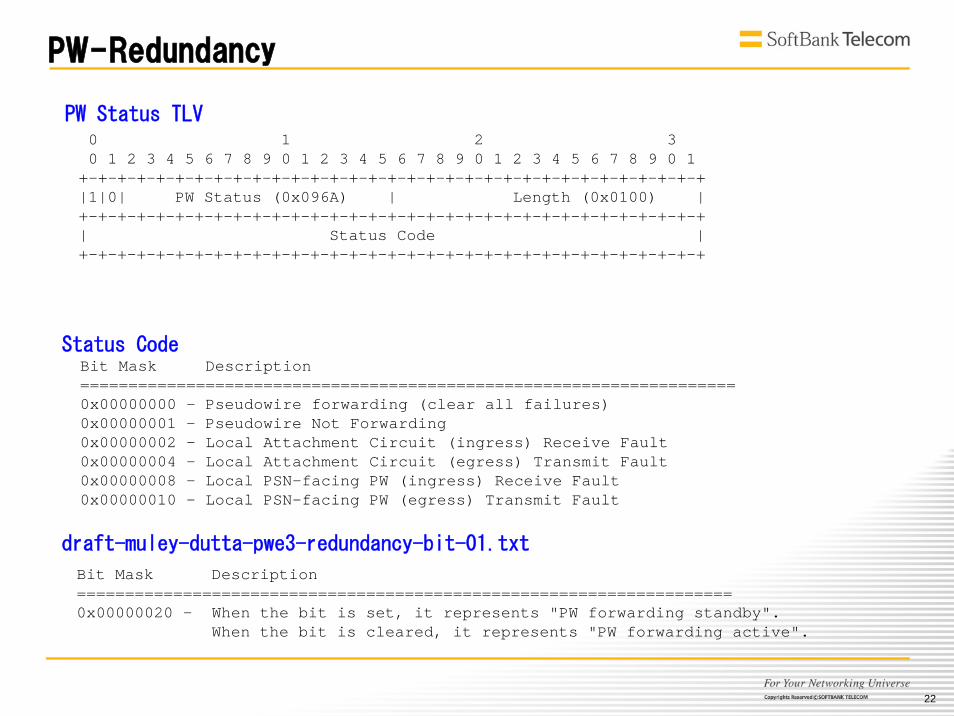
PW-Redundancy
draft-muley-dutta-pwe3-redundancy-bit-01.txt
0 1 2 30 1 2 3 4 5 6 7 8 9 0 1 2 3 4 5 6 7 8 9 0 1 2 3 4 5 6 7 8 9 0 1
+-+-+-+-+-+-+-+-+-+-+-+-+-+-+-+-+-+-+-+-+-+-+-+-+-+-+-+-+-+-+-+-+|1|0| PW Status (0x096A) | Length (0x0100) |+-+-+-+-+-+-+-+-+-+-+-+-+-+-+-+-+-+-+-+-+-+-+-+-+-+-+-+-+-+-+-+-+| Status Code |+-+-+-+-+-+-+-+-+-+-+-+-+-+-+-+-+-+-+-+-+-+-+-+-+-+-+-+-+-+-+-+-+
PW Status TLV
Bit Mask Description==================================================================== 0x00000000 - Pseudowire forwarding (clear all failures) 0x00000001 - Pseudowire Not Forwarding0x00000002 - Local Attachment Circuit (ingress) Receive Fault0x00000004 - Local Attachment Circuit (egress) Transmit Fault0x00000008 - Local PSN-facing PW (ingress) Receive Fault0x00000010 - Local PSN-facing PW (egress) Transmit Fault
Status Code
Bit Mask Description==================================================================== 0x00000020 - When the bit is set, it represents "PW forwarding standby".
When the bit is cleared, it represents "PW forwarding active".
23
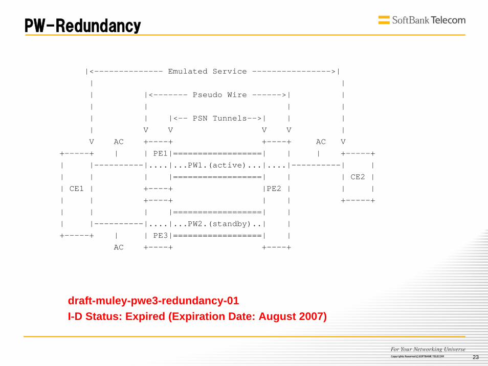
PW-Redundancy
|<-------------- Emulated Service ---------------->| | | | |<------- Pseudo Wire ------>| | | | | | | | |<-- PSN Tunnels-->| | | | V V V V | V AC +----+ +----+ AC V
+-----+ | | PE1|==================| | | +-----+ | |----------|....|...PW1.(active)...|....|----------| | | | | |==================| | | CE2 | | CE1 | +----+ |PE2 | | | | | +----+ | | +-----+ | | | |==================| | | |----------|....|...PW2.(standby)..| | +-----+ | | PE3|==================| |
AC +----+ +----+
draft-muley-pwe3-redundancy-01 I-D Status: Expired (Expiration Date: August 2007)
24
L1切替スイッチ
L1切替スイッチ
MPLS
Core
P2 P4PE2
PE1 PE3
PE4
P3P1
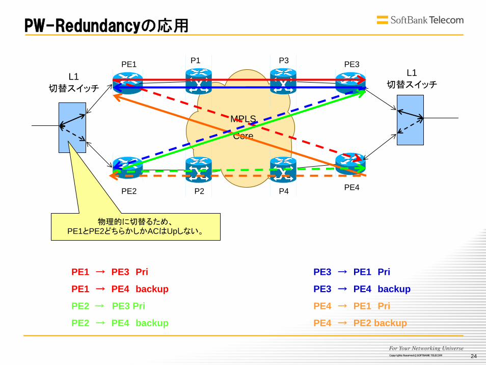
物理的に切替るため、PE1とPE2どちらかしかACはUpしない。
PE3 → PE1 Pri
PE3 → PE4 backup
PE4 → PE1 Pri
PE4 → PE2 backup
PE1 → PE3 Pri
PE1 → PE4 backup
PE2 → PE3 Pri
PE2 → PE4 backup
PW-Redundancyの応用

25
L1切替スイッチ
L1切替スイッチ
MPLS
Core
P2 P4PE2
PE1 PE3
PE4
P3P1
PE3 → PE1 Pri
PE3 → PE4 backup
PE4 → PE1 Pri
PE4 → PE2 backup
PE1 → PE3 Pri
PE1 → PE4 backup
PE2 → PE3 Pri
PE2 → PE4 backup
PW-Redundancyの応用:切替動作
26
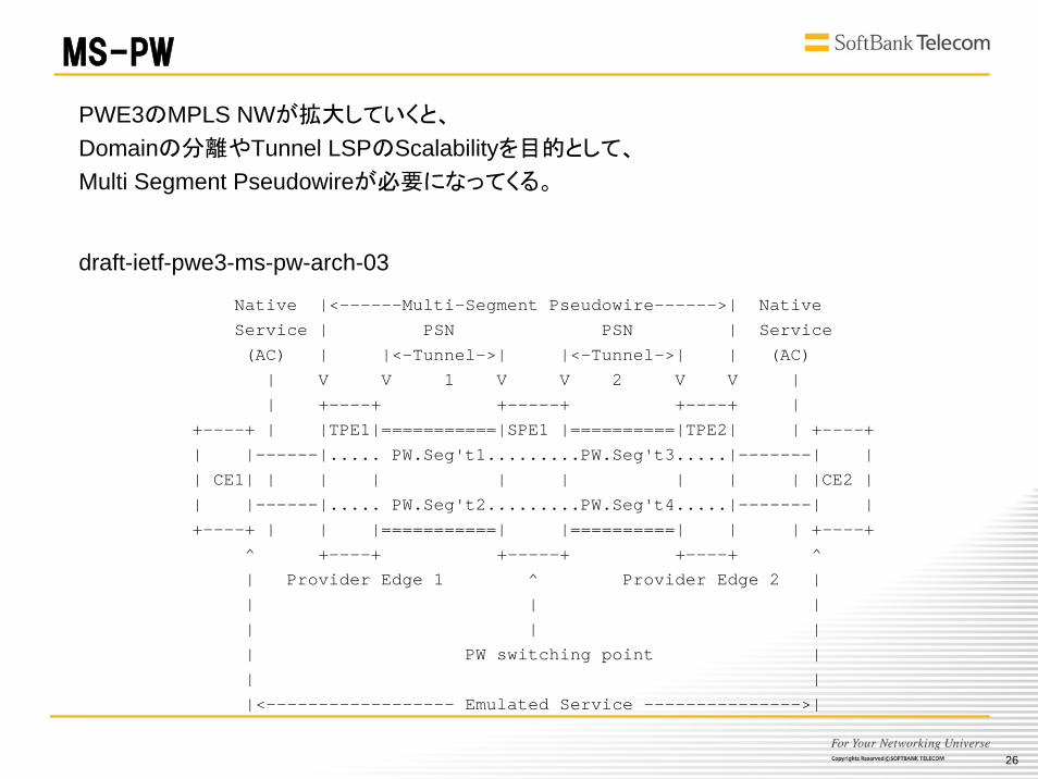
draft-ietf-pwe3-ms-pw-arch-03
Native |<------Multi-Segment Pseudowire------>| NativeService | PSN PSN | Service(AC) | |<-Tunnel->| |<-Tunnel->| | (AC)
| V V 1 V V 2 V V || +----+ +-----+ +----+ |
+----+ | |TPE1|===========|SPE1 |==========|TPE2| | +----+| |------|..... PW.Seg't1.........PW.Seg't3.....|-------| || CE1| | | | | | | | | |CE2 || |------|..... PW.Seg't2.........PW.Seg't4.....|-------| |+----+ | | |===========| |==========| | | +----+
^ +----+ +-----+ +----+ ^| Provider Edge 1 ^ Provider Edge 2 || | || | || PW switching point || ||<------------------ Emulated Service --------------->|
MS-PW
PWE3のMPLS NWが拡大していくと、
Domainの分離やTunnel LSPのScalabilityを目的として、
Multi Segment Pseudowireが必要になってくる。
27
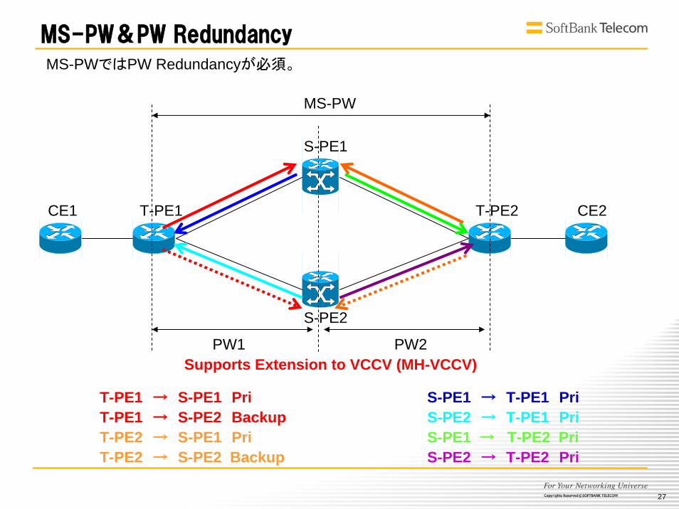
MS-PW&PW Redundancy
T-PE1
S-PE1
CE1
S-PE2
T-PE2 CE2
S-PE1 → T-PE1 PriS-PE2 → T-PE1 PriS-PE1 → T-PE2 PriS-PE2 → T-PE2 Pri
T-PE1 → S-PE1 PriT-PE1 → S-PE2 BackupT-PE2 → S-PE1 PriT-PE2 → S-PE2 Backup
MS-PW
PW1 PW2Supports Extension to VCCV (MH-VCCV)
MS-PWではPW Redundancyが必須。
28
Traffic Engineering/Management
&
QOS
29
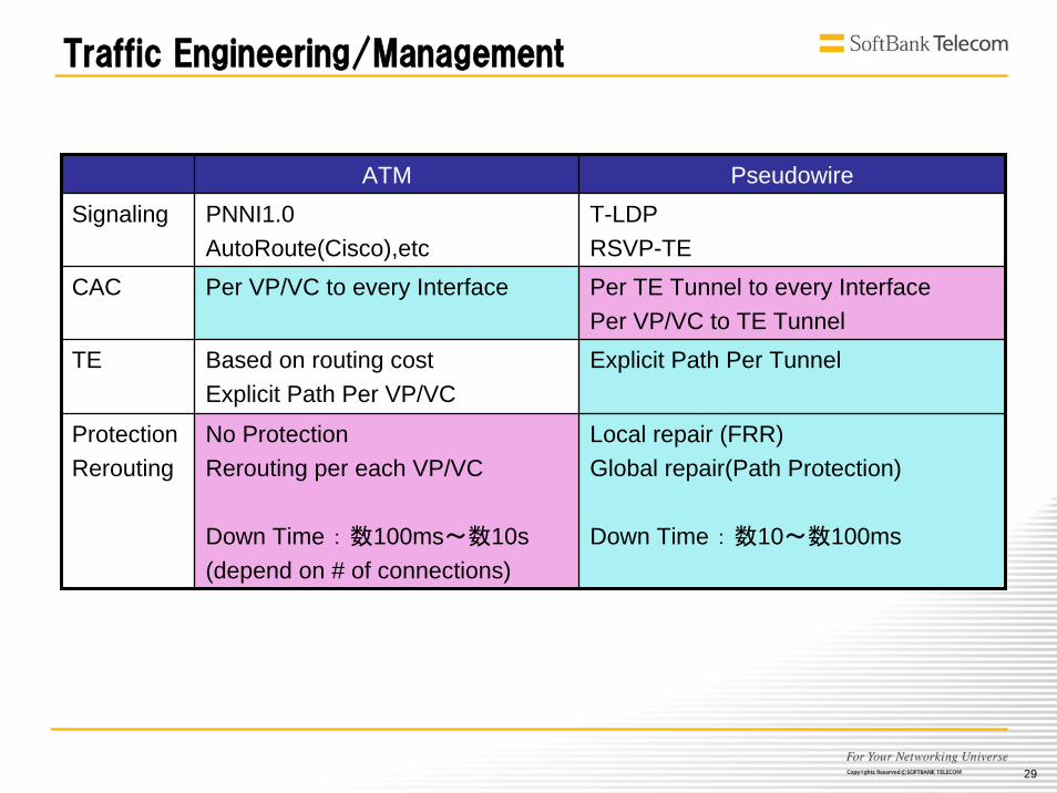
Traffic Engineering/Management
ATM PseudowireSignaling PNNI1.0
AutoRoute(Cisco),etcT-LDPRSVP-TE
CAC Per VP/VC to every Interface Per TE Tunnel to every InterfacePer VP/VC to TE Tunnel
TE Based on routing costExplicit Path Per VP/VC
Explicit Path Per Tunnel
ProtectionRerouting
No ProtectionRerouting per each VP/VC
Down Time : 数100ms~数10s(depend on # of connections)
Local repair (FRR)Global repair(Path Protection)
Down Time : 数10~数100ms
30
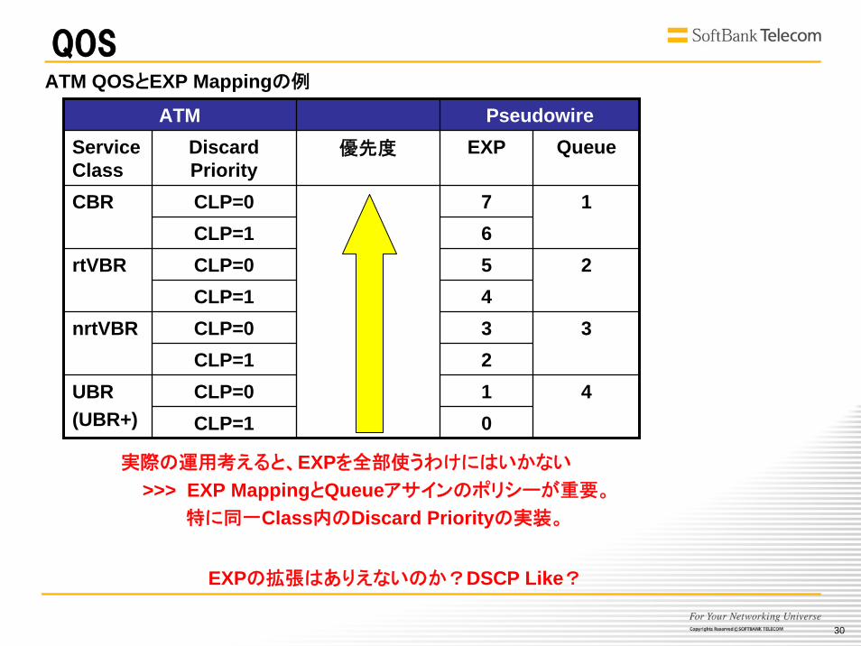
QOS
ATM PseudowireService Class
Discard Priority
優先度 EXP Queue
CLP=0 7654321
CBR
0
CLP=11
CLP=0rtVBRCLP=1
CLP=1CLP=0UBR
(UBR+)4
2
CLP=0nrtVBR 3
CLP=1
ATM QOSとEXP Mappingの例
実際の運用考えると、EXPを全部使うわけにはいかない
>>> EXP MappingとQueueアサインのポリシーが重要。
特に同一Class内のDiscard Priorityの実装。
EXPの拡張はありえないのか?DSCP Like?
31
MPLSへの期待と要望
Per PWでCACしたい。
Tunnel帯域 >> ∑PW帯域だと、無駄が多くなる。
こまめにTunnel帯域増が必要になる。
Tunnelごとに収容しているPWと合計帯域、帯域使用率が見たい。
外部DBでの管理は可能だが、
装置側で簡単に見れるコマンド、MIBがあるとうれしい。
PWごとに乗せるTunnelを選択したい。Tunnel Selection
EXP 8Classの制限が何とかならないか
PWを提供するMPLS NWの拡張を考慮して、
Inter-Area TEは必須。(with Protection)
32
OAM
33
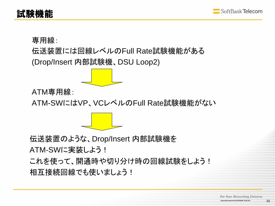
試験機能
ATM専用線:
ATM-SWにはVP、VCレベルのFull Rate試験機能がない
専用線:
伝送装置には回線レベルのFull Rate試験機能がある
(Drop/Insert 内部試験機、DSU Loop2)
伝送装置のような、Drop/Insert 内部試験機を
ATM-SWに実装しよう!
これを使って、開通時や切り分け時の回線試験をしよう!
相互接続回線でも使いましょう!
34
HeaderOAMtype
Functiontype
ReservedFunction specific field
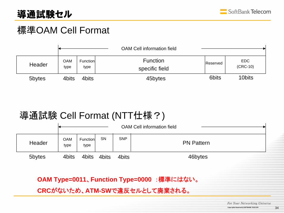
導通試験セル
EDC(CRC-10)
OAM Cell information field
5bytes 4bits 4bits 45bytes 6bits 10bits
HeaderOAMtype
Functiontype PN Pattern
OAM Cell information field
5bytes 4bits 4bits 46bytes
SN SNP
4bits 4bits
標準OAM Cell Format
導通試験 Cell Format (NTT仕様?)
OAM Type=0011、Function Type=0000 :標準にはない。
CRCがないため、ATM-SWで違反セルとして廃棄される。
35
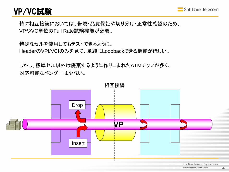
VP/VC試験
VP
Insert
Drop
相互接続
特に相互接続においては、帯域・品質保証や切り分け・正常性確認のため、
VPやVC単位のFull Rate試験機能が必要。
特殊なセルを使用してもテストできるように、
HeaderのVPI/VCIのみを見て、単純にLoopbackできる機能がほしい。
しかし、標準セル以外は廃棄するように作りこまれたATMチップが多く、
対応可能なベンダーは少ない。
36
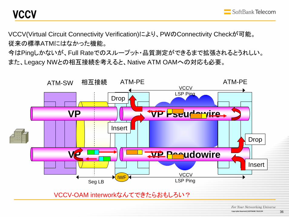
VCCV
VP
相互接続ATM-SW ATM-PE ATM-PE
VP PseudowireInsert
Drop
VCCVLSP Ping
VCCV(Virtual Circuit Connectivity Verification)により、PWのConnectivity Checkが可能。
従来の標準ATMにはなかった機能。
今はPingしかないが、Full Rateでのスループット・品質測定ができるまで拡張されるとうれしい。
また、Legacy NWとの相互接続を考えると、Native ATM OAMへの対応も必要。
VP VP Pseudowire
VCCVLSP Ping
Insert
Drop
Seg LB
VCCV-OAM interworkなんてできたらおもしろい?
IWF

37
MPLS Control Channel (CC) Types:
Bit (Value) DescriptionBit 0 (0x01) - Type 1: PWE3 Control Word with 0001b as
first nibble (PW-ACH, see [RFC4385])Bit 1 (0x02) - Type 2: MPLS Router Alert LabelBit 2 (0x04) - Type 3: MPLS PW Label with TTL == 1Bit 3 (0x08) - ReservedBit 4 (0x10) - ReservedBit 5 (0x20) - ReservedBit 6 (0x40) - ReservedBit 7 (0x80) - Reserved
The VCCV parameter ID is defined as follows in [RFC4446]:
Parameter ID Length Description0x0c 4 VCCV
The format of the VCCV parameter field is as follows:0 1 2 30 1 2 3 4 5 6 7 8 9 0 1 2 3 4 5 6 7 8 9 0 1 2 3 4 5 6 7 8 9 0 1
+-+-+-+-+-+-+-+-+-+-+-+-+-+-+-+-+-+-+-+-+-+-+-+-+-+-+-+-+-+-+-+-+| 0x0c | 0x04 | CC Types | CV Types |+-+-+-+-+-+-+-+-+-+-+-+-+-+-+-+-+-+-+-+-+-+-+-+-+-+-+-+-+-+-+-+-+
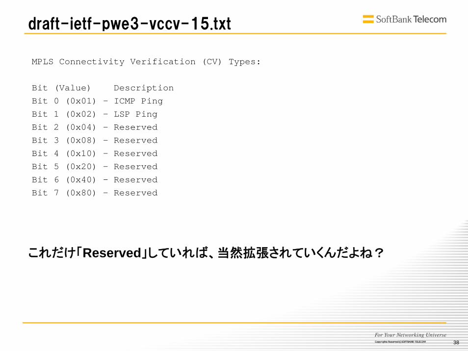
draft-ietf-pwe3-vccv-15.txt
38
MPLS Connectivity Verification (CV) Types:
Bit (Value) DescriptionBit 0 (0x01) - ICMP PingBit 1 (0x02) - LSP PingBit 2 (0x04) - ReservedBit 3 (0x08) - ReservedBit 4 (0x10) - ReservedBit 5 (0x20) - ReservedBit 6 (0x40) - ReservedBit 7 (0x80) - Reserved
draft-ietf-pwe3-vccv-15.txt
これだけ「Reserved」していれば、当然拡張されていくんだよね?
39
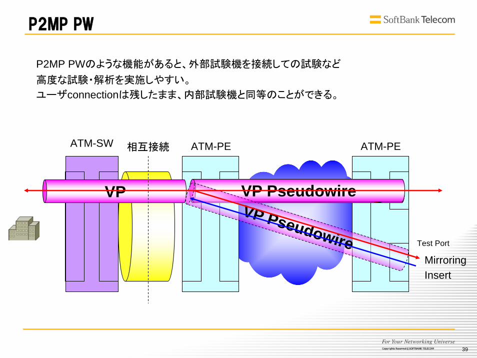
P2MP PW
P2MP PWのような機能があると、外部試験機を接続しての試験など
高度な試験・解析を実施しやすい。
ユーザconnectionは残したまま、内部試験機と同等のことができる。
VP
相互接続 ATM-PEATM-SW ATM-PE
VP Pseudowire
Test Port
VP PseudowireVP Pseudowire
InsertMirroring
40
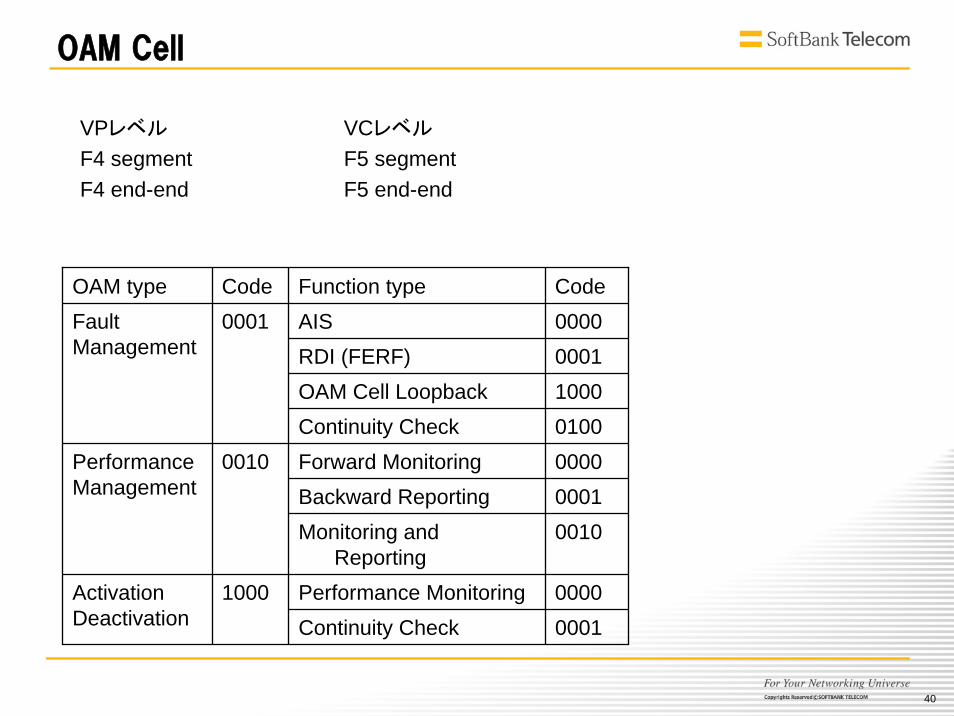
OAM Cell
OAM type Code Function type CodeAISRDI (FERF) OAM Cell Loopback Continuity Check Forward Monitoring Backward Reporting Monitoring and
Reporting Performance Monitoring 0000Activation
Deactivation 1000
Continuity Check 0001
000000011000010000000001
0001
0010
0010
FaultManagement
PerformanceManagement
VPレベル
F4 segmentF4 end-end
VCレベル
F5 segmentF5 end-end
41
VP/VC
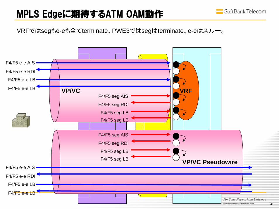
MPLS Edgeに期待するATM OAM動作
VRF
VP/VC Pseudowire
F4/F5 e-e AIS
F4/F5 e-e RDI
F4/F5 e-e LB
F4/F5 e-e LB
F4/F5 seg AIS
F4/F5 seg RDI
F4/F5 seg LBF4/F5 seg LB
F4/F5 e-e AIS
F4/F5 e-e RDI
F4/F5 e-e LB
F4/F5 e-e LB
F4/F5 seg AIS
F4/F5 seg RDI
F4/F5 seg LBF4/F5 seg LB
VRFではsegもe-eも全てterminate、PWE3ではsegはterminate、e-eはスルー。
42
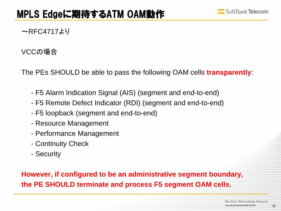
~RFC4717より
VCCの場合
The PEs SHOULD be able to pass the following OAM cells transparently:
- F5 Alarm Indication Signal (AIS) (segment and end-to-end)- F5 Remote Defect Indicator (RDI) (segment and end-to-end)- F5 loopback (segment and end-to-end)- Resource Management- Performance Management- Continuity Check- Security
However, if configured to be an administrative segment boundary,the PE SHOULD terminate and process F5 segment OAM cells.
MPLS Edgeに期待するATM OAM動作
43
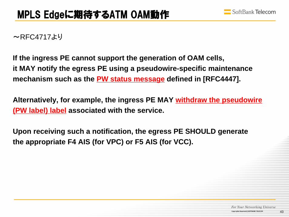
~RFC4717より
If the ingress PE cannot support the generation of OAM cells, it MAY notify the egress PE using a pseudowire-specific maintenance mechanism such as the PW status message defined in [RFC4447].
Alternatively, for example, the ingress PE MAY withdraw the pseudowire(PW label) label associated with the service.
Upon receiving such a notification, the egress PE SHOULD generatethe appropriate F4 AIS (for VPC) or F5 AIS (for VCC).
MPLS Edgeに期待するATM OAM動作
44
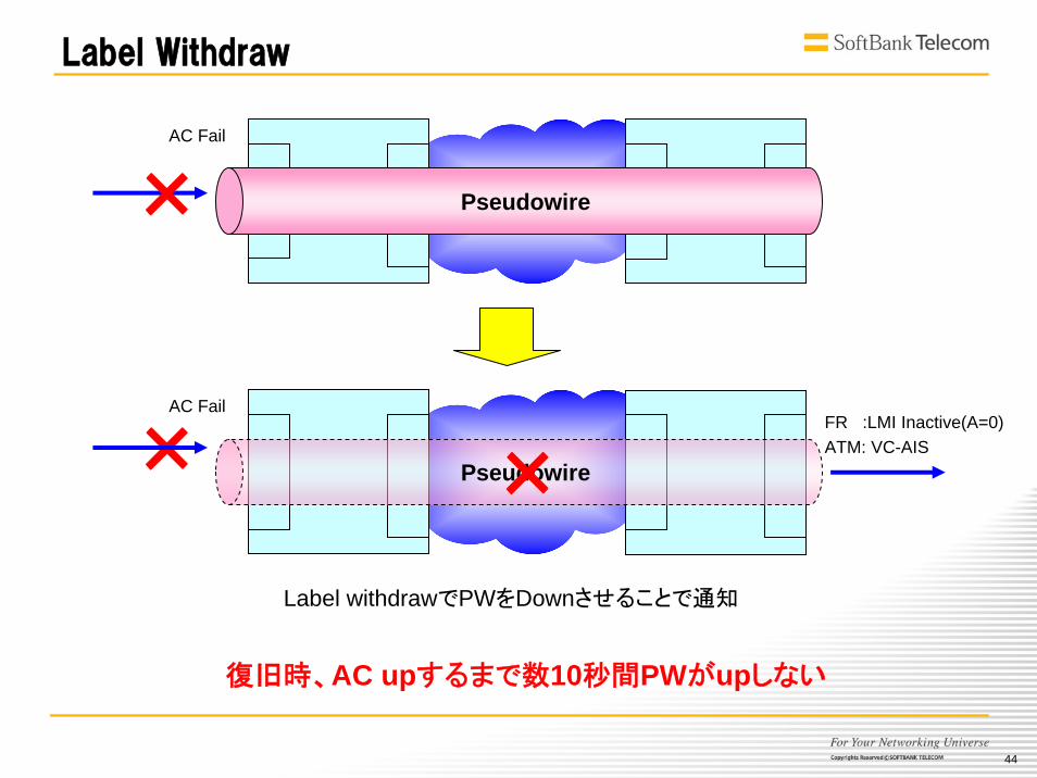
Label Withdraw
Pseudowire×
Pseudowire× ×AC Fail
AC Fail
FR :LMI Inactive(A=0)ATM: VC-AIS
Label withdrawでPWをDownさせることで通知
復旧時、AC upするまで数10秒間PWがupしない
45
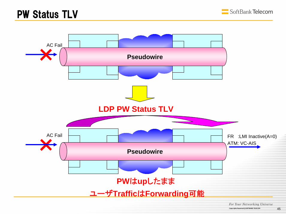
PW Status TLV
Pseudowire×
Pseudowire×
LDP PW Status TLV
PWはupしたまま
AC Fail
AC Fail
FR :LMI Inactive(A=0)ATM: VC-AIS
ユーザTrafficはForwarding可能

46
ATM OAM実装の課題
同一Port上にVRF(terminate end)とPWE3の混在
Segmentとend-end OAM cellの区別
(Segment Boundary)
既存ATMとのInterworkを考慮したOAM Mapping
draft-ietf-pwe3-oam-msg-map-05I-D Status: Expired (Expiration Date: September 2007 )
47
1.Legacy NW Migrationの必要性と目的
2.Requirement
3.現状の問題点
4.Migration Scenarioの検討
5.Summary

48
NTTNTTNCCNCC
NTTNTTNCCNCC
現状のNetwork
FR/ATMFR/ATM
IPIP--VPNVPN
EthernetEthernet
49
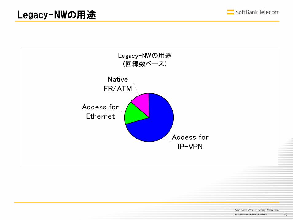
Legacy-NWの用途
Legacy-NWの用途(回線数ベース)
Access forEthernet
NativeFR/ATM
Access forIP-VPN

50
Multi Service Edge
MPLSMPLSCoreCore
NTTNTTNCCNCC
NTTNTTNCCNCCFR/ATMFR/ATM
IPIP--VPNVPN
EthernetEthernet
こんなことをやってみたくなる
51
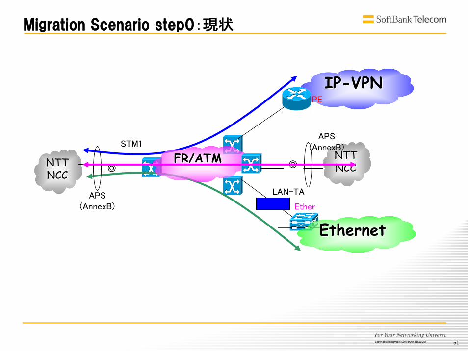
NTTNTTNCCNCC
NTTNTTNCCNCC
IPIP--VPNVPN
Ether
STM1
PE
◎
APS(AnnexB)
FR/ATMFR/ATM
EthernetEthernet
◎
APS(AnnexB)
Migration Scenario step0:現状
LAN-TA
52
NTTNTTNCCNCCNTTNTT
NCCNCC
IPIP--VPNVPN
FR/ATMFR/ATM
EthernetEthernet
LAN-TA
Ether
STM1
PE
◎
STM1
APS(AnnexB)
APS(AnnexB)
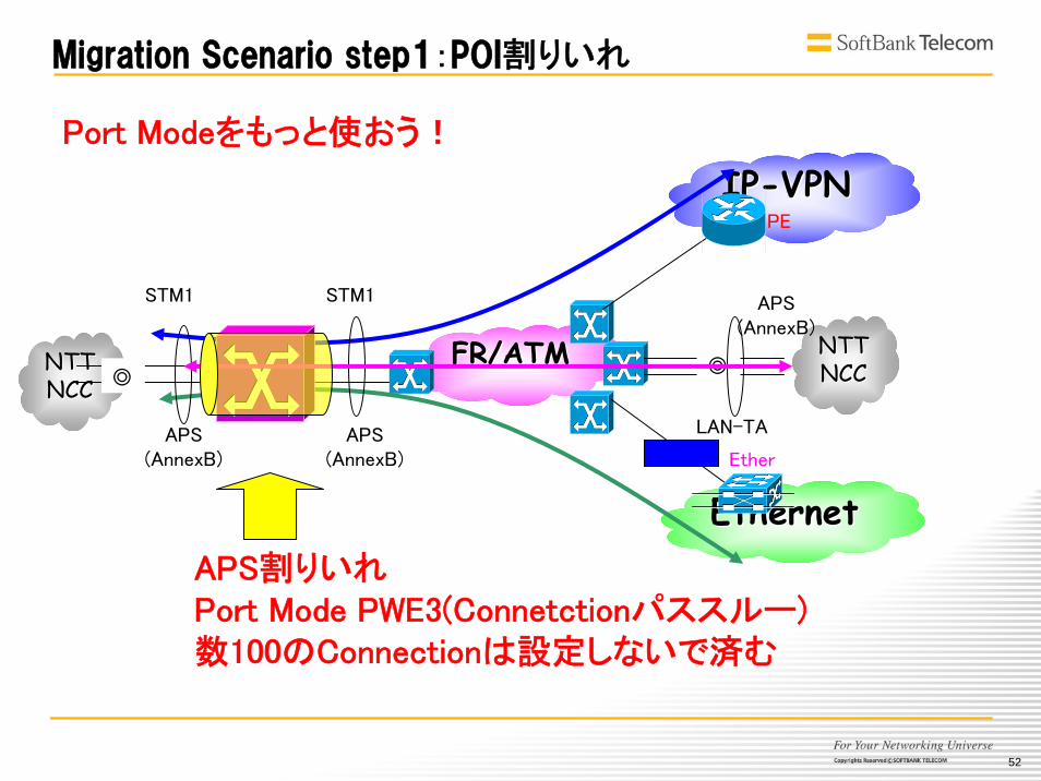
APS割りいれPort Mode PWE3(Connetctionパススルー)数100のConnectionは設定しないで済む
◎
APS(AnnexB)
Migration Scenario step1:POI割りいれ
Port Modeをもっと使おう!
53
NTTNTTNCCNCC
NTTNTTNCCNCC
EthernetEthernet(VPLS)(VPLS)
PseudowirePseudowire
FR/ATM
IPIP--VPNVPN(MPLS)(MPLS)
LAN-TAEther
PE
◎STM1(ATM)
APS(AnnexB)APS
(AnnexB)
GbE(VLAN)
PE
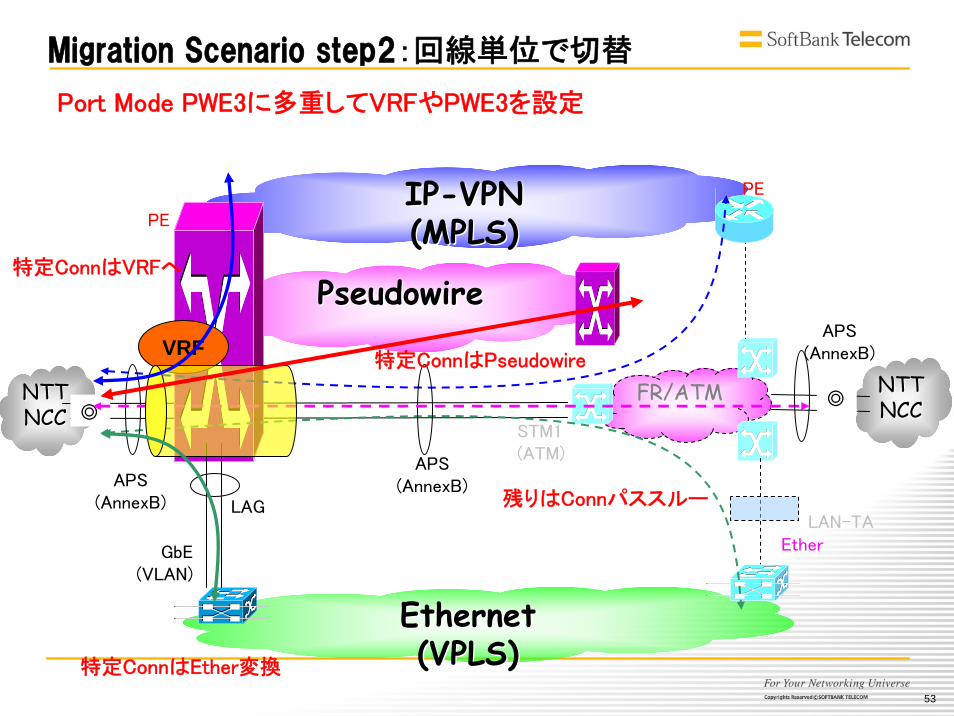
特定ConnはEther変換
LAG
VRF
残りはConnパススルー
特定ConnはVRFへ
特定ConnはPseudowire
Migration Scenario step2:回線単位で切替
◎
APS(AnnexB)
Port Mode PWE3に多重してVRFやPWE3を設定
54
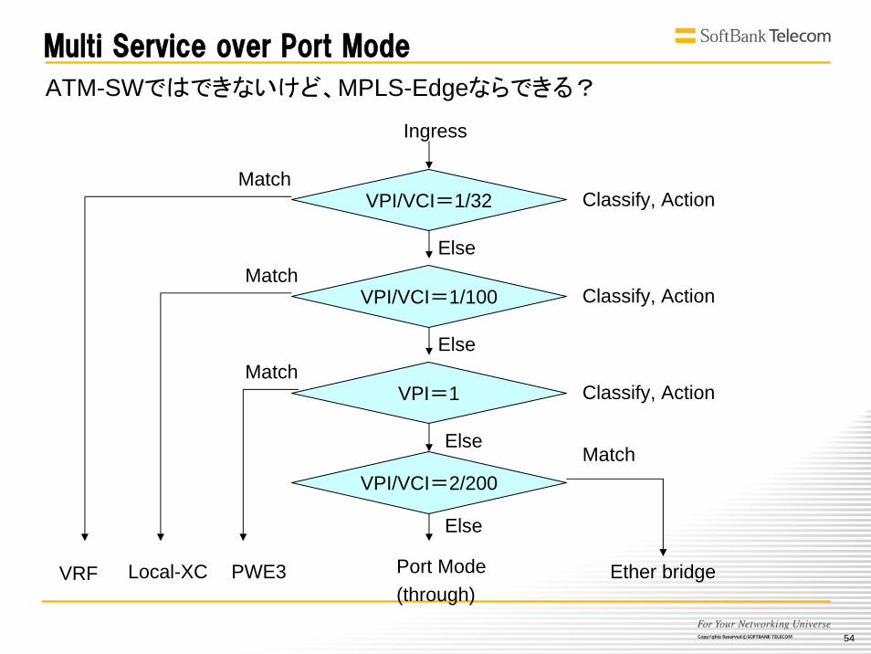
Ingress
Ether bridgeVRF PWE3
VPI/VCI=1/32
Port Mode(through)
VPI/VCI=1/100
VPI=1
Classify, Action
Classify, Action
Classify, Action
Match
MatchElse
Else
ATM-SWではできないけど、MPLS-Edgeならできる?
Multi Service over Port Mode
Match
Else
VPI/VCI=2/200
Local-XC
Match
Else
55
NTTNTTNCCNCC
NTTNTTNCCNCC
EthernetEthernet(VPLS)(VPLS)
PseudowirePseudowire
IPIP--VPNVPN(MPLS)(MPLS)
◎
APS(AnnexB)
GbE(VLAN)
LAG
VRF
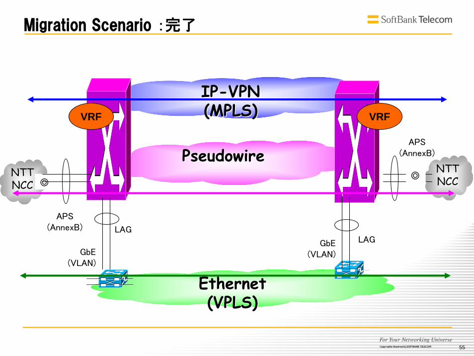
Migration Scenario :完了
◎
APS(AnnexB)
GbE(VLAN)
LAG
VRF
56
MPLSMPLSCoreCore
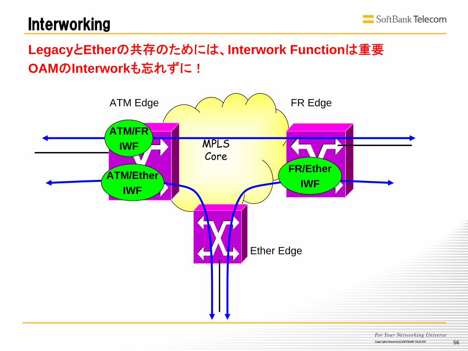
Interworking
ATM Edge FR Edge
Ether Edge
ATM/FRIWF
ATM/EtherIWF
FR/EtherIWF
LegacyとEtherの共存のためには、Interwork Functionは重要
OAMのInterworkも忘れずに!
57
みんな簡単に統合って言うけど
でも
Technologyの進歩だけでは
解決しきれない課題がもうひとつ
58
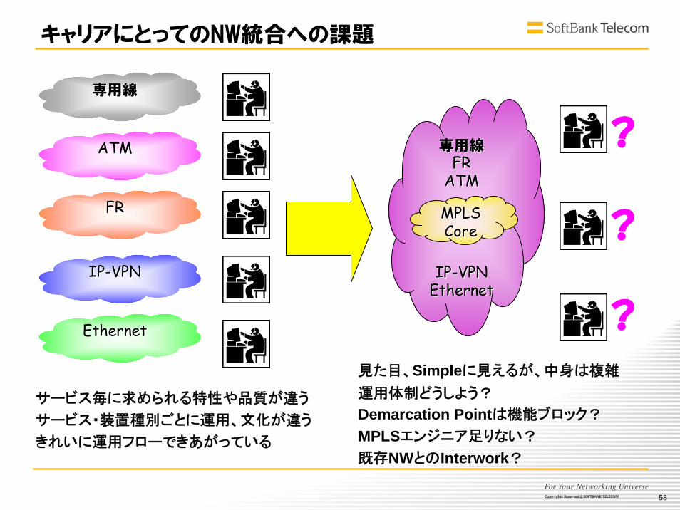
キャリアにとってのNW統合への課題
ATMATM
FRFR
IPIP--VPNVPN
EthernetEthernet
専用線専用線
専用線専用線FRFR
ATMATM
IPIP--VPNVPNEthernetEthernet
MPLSMPLSCoreCore
?
?
?見た目、Simpleに見えるが、中身は複雑
運用体制どうしよう?
Demarcation Pointは機能ブロック?
MPLSエンジニア足りない?
既存NWとのInterwork?
サービス毎に求められる特性や品質が違う
サービス・装置種別ごとに運用、文化が違う
きれいに運用フローできあがっている
59
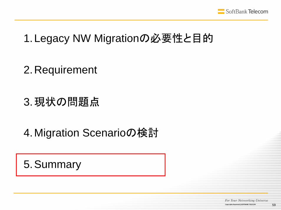
1.Legacy NW Migrationの必要性と目的
2.Requirement
3.現状の問題点
4.Migration Scenarioの検討
5.Summary
60
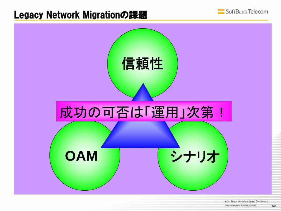
Legacy Network Migrationの課題
シナリオOAM
信頼性
成功の可否は「運用」次第!
61
Thank you!
ご清聴ありがとうございました!
Top Related