


Languages
Pages
Legal

www.lsis.com
Super Solution
Super Solution
LS Medium Voltage Vacuum Contactors

2 I
Customer satisfaction through quality and service - LS medium voltage vacuum contactorsLS medium voltage vacuum contactors using LS vacuum interrupters manufactured with worldclass technology are type tested in LS PT & T that is accredited high power test lab by worldclass KOLAS.
Contents
I 3
Customer satisfaction through quality and service - LS medium voltage vacuum contactors
Features ................................................................................... 4
Technical data ................................................................ 8Ordering Information .......................................... 10
External view ................................................................ 12
Safety components .............................................. 13
Internal structure ..................................................... 14
Vacuum interrupters ........................................... 15Accessories ........................................................................ 16
Drawing operations ....................................................... 17
Auxiliary Device .................................................................. 18
Electrical circuit diagram ........................................ 21
Mechanical Interlock Type
Electrical Circuit Diagram ..................................... 23
External Dimensions ................................................... 25
Power fuse ................................................................................. 32
Power fuse selection guides ............................ 33
Selection tables ................................................................... 34
Coordination graph ........................................................ 36
Operation curves ....................................................... 38

4 I
General Description
Combination Fixed TypeFixed Type Drawout Type
LS Susol Vacuum ContactorsWe have the major technology that others can not catch up.LS Susol vacuum contactors provide high withstand - current strength and switching capacity as well as versatile auxiliary functions.
LS Susol vacuum contactors are mainly used for the switching of motors, transformers, capacitors in AC power lines. They can be installed in multi - stack cubicles.A vacuum contactor comprises several assemblies such as switching mechanism including vacuum interrupters, magnetic actuator, high strength molded front cover and auxiliary devices. Stable and high operating cycle is executed by the vacuum interrupters made of high alumina ceramic tube which makes it possible to degas in a high temperature with excellent mechanical strength.
Actuating is available either at instantaneous or continuous excitation. Functions for safety in connecting and disconnecting are also provided.
Variety
Reliability
Up grade
Safety
Compatibility
I 5
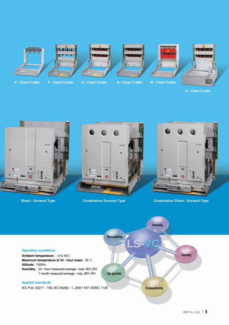
F - Class CradleE - Class Cradle G - Class Cradle B - Class Cradle
H - Class Cradle
M - Class Cradle
Direct - Drawout Type Combination Drawout Type Combination Direct - Drawout Type
Operation conditionsAmbient temperature : - 5 to 40℃Maximum temperature of 24 - hour mean : 35 ℃Altitude : 1000mHumidity : �24 - hour measured average - max. 95% RH 1 month measured average - max. 90% RH
Applied standardsIEC Pub. 62271 - 106, IEC 60282 - 1, JEM 1167, KEMC 1126
[ Safety ]LS Susol vacuum contactors provide several auxiliary
functions for safe and comfortable use.
6 I
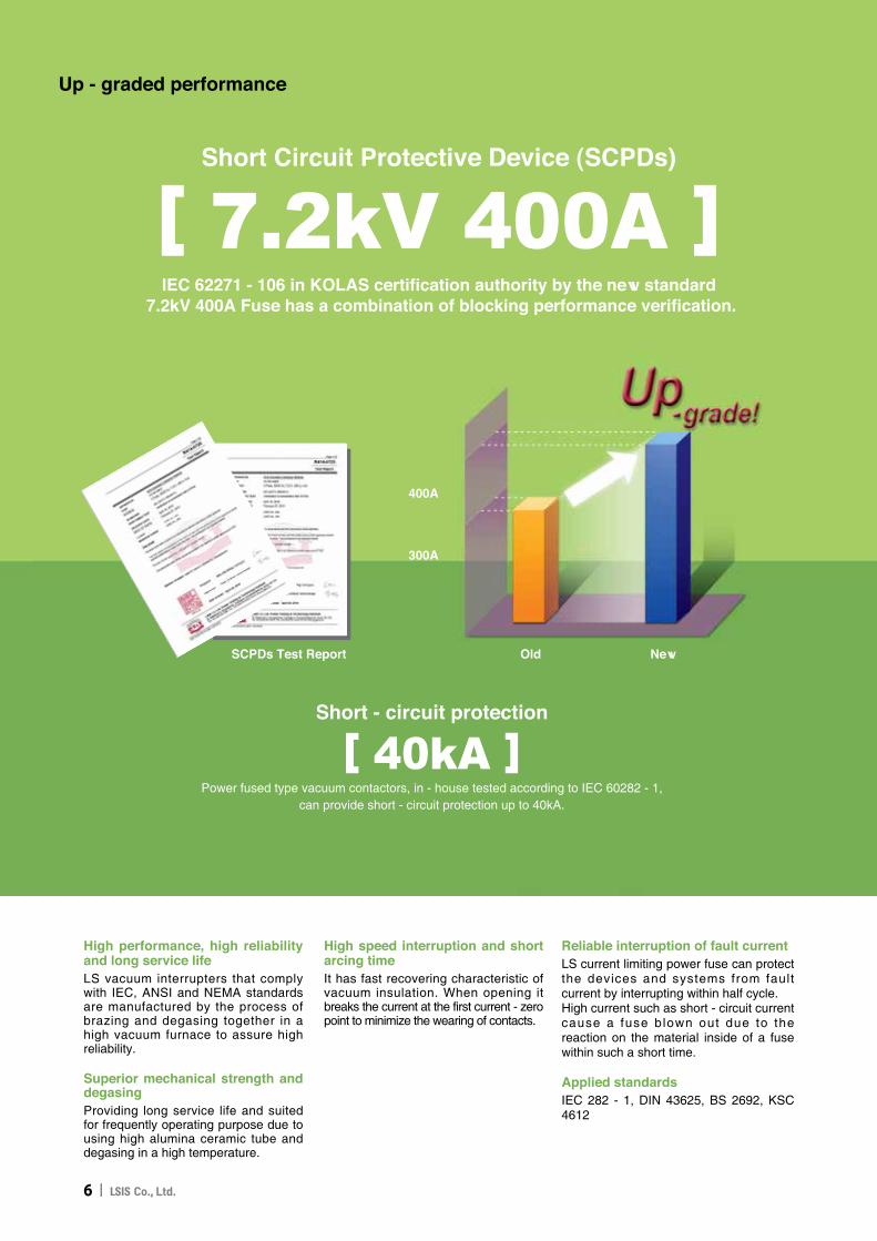
[ 7.2kV 400A ]IEC 62271 - 106 in KOLAS certification authority by the new standard
7.2kV 400A Fuse has a combination of blocking performance verification.
Short Circuit Protective Device (SCPDs)
Old New
400A
300A
SCPDs Test Report
Up - graded performance
[ 40kA ]Power fused type vacuum contactors, in - house tested according to IEC 60282 - 1,
can provide short - circuit protection up to 40kA.
Short - circuit protection
High performance, high reliability and long service lifeLS vacuum interrupters that comply with IEC, ANSI and NEMA standards are manufactured by the process of brazing and degasing together in a high vacuum furnace to assure high reliability.
Superior mechanical strength and degasingProviding long service life and suited for frequently operating purpose due to using high alumina ceramic tube and degasing in a high temperature.
High speed interruption and short arcing timeIt has fast recovering characteristic of vacuum insulation. When opening it breaks the current at the first current - zero point to minimize the wearing of contacts.
Reliable interruption of fault currentLS current limiting power fuse can protect the devices and systems from fault current by interrupting within half cycle.High current such as short - circuit current cause a fuse blown out due to the reaction on the material inside of a fuse within such a short time.
Applied standardsIEC 282 - 1, DIN 43625, BS 2692, KSC 4612

[ Safety ]LS Susol vacuum contactors provide several auxiliary
functions for safe and comfortable use.
Mechanical Interlock Type
■ Interlock button
■ Drawout cradle for MCSG
■ One - molded fuse holder
■ Fuse checher and micro switch
■ Unification bushing
■ Mechanical interlock type
Personnel safety
Additional Equipment
Suitable for Metal Clad SwitchgearThe structure of G type cradle unification bushings and single - molded fuse - holder barrier enables vacuum contactors to build Metal Clad Switchgears.
Directly withdrawable equipmentThis enables the withdrawing of a vacuum contactor from a panel without opening a door to prevent any possibility of electric shock.
Interlock For the safety of a operator interlock is equipped as standard.
Auxiliary contactsAvailable up to 5NO+5NC.
Contactor over contactor arrangement
I 7

Technical data
Single type Fixed (Z) type Drawout (D) type Direct - drawout (K) type
TypeContinuous Excitation (E) VC-3Z- VC-6Z- VC-3Z- VC-6Z- VC-3D- VC-6D- VC-3D- VC-6D- VC-3K- VC-6K- VC-3K- VC-6K-
Instantaneous Excitation (L) 42E 42E 44E 44E 42E 42E 44E 44E 42E 42E 44E 44E
Rated operation voltage [kV] 3.3 6.6 3.3 6.6 3.3 6.6 3.3 6.6 3.3 6.6 3.3 6.6Rated voltage Ur[kV] 3.6 7.2 3.6 7.2 3.6 7.2 3.6 7.2 3.6 7.2 3.6 7.2Rated operational current le[A] 200 400 200 400 200 400Rated frequency fr[Hz] 50/60Rated breaking current (kA, O - 3min - CO - 2min - CO) 4Rated short - time current (kA - sec) 2.4kA-30s, 4kA-10s, 6kA-2s, 6.3kA-1sRated short - time peak current (kApeak - 0.5Cycle) 60Switching frequency(AC3) [op./hr] E : Continuous 1200, L : Instantaneous 300Lifetime Mechanical [×10, 000operations] E : Continuous 300, L : Instantaneous 50
Electrical [×10, 000operations] 30Impulse withstand Up[kVp] 60Dielectric strength Ud[kV/1min] 20Excitation method E : Continuous, L : InstantaneousControl voltage [V] DC/AC 110V, 125V, 220VAuxiliary contact
Current [A] 10 (AC)Voltage [V] 600max ~ 48min
Arrangement Continuous 3NO3NC, Instantaneous 2NO2NC 2NO2NC
Max. Applicable
Motors [kW] 750 1,500 1,500 3,000 750 1,500 1,500 3,000 750 1,500 1,500 3,000Transformers [kVA] 1,000 2,000 2,000 4,000 1,000 2,000 2,000 4,000 1,000 2,000 2,000 4,000Capacitors [kVA] 750 1,500 1,200 2,000 750 1,500 1,200 2,000 750 1,500 1,200 2,000
Weight [kg] 24 41 56
Power fusePower fuses can be installed into combination(G, B, F) type contactors for the protection of equipments and systems from short - circuit.Fuse ratings are selected properly after system analysis and some accessories such as fuse link clips should be selected by the fuse rating.
8

Standard Type Ratedvoltage(kV) Rated current(A) Diameter
(mm)Length(mm)
DIN Type
LFL - 3/6G - B 3.6/7.2 5, 10, 20, 30, 40, 50, 63, 75, 100
45
192LFL - 3/6G - B 3.6/7.2 125 292LFL - 3G - B 3.6 160, 200 292LFL - 6G - B 7.2 160, 200 292
KS Type
Generaluse
LFL - 3/6G - 3.6/7.25(T1.5), 10(T3), 20(T7.5),
30(T15), 40(T20), 50(T30), 60(T30) 50 261
75(T50), 100(T75) 60 311
LFL - 3G - 3.6150(T100), 200(T150) 60 311300(T250), 400(T300) 77 311
LFL - 6G - 7.2 150(T100), 200(T150) 77 311
Formotors
LFL - 3M - 3.6M20, M50, M100 60 200
M150, M200 77 200M300 , (M400) 87 250
LFL - 6M - 7.2M20, M50 60 311
M100, M150 , M200 77 350M300 , (M400) 87 450
LFL - 6G - 300, 400 is not possible to combine with VC
Power fuse ratings combination type
Note) Load capacity is different from ratings of Power Fuse T is applied to the load capacity varies depending on the power rating of the fuse
Combination(PF) type Combination Drawout(G) Type Combination Direct-Drawout(B) Type Combination Fixed(F) Type
TypeContinuous Excitation (E) VC-3G VC-6G VC-3G VC-6G VC-3B VC-6B VC-3B VC-6B VC-3F VC-6F VC-3F VC-6FInstantaneous Excitation (L) -42E -42E -44E -44E -42E -42E -44E -44E -42E -42E -44E -44E
Rated operation voltage [kV] 3.3 6.6 3.3 6.6 3.3 6.6 3.3 6.6 3.3 6.6 3.3 6.6Rated voltage Ur[kV] 3.6 7.2 3.6 7.2 3.6 7.2 3.6 7.2 3.6 7.2 3.6 7.2Rated operational current le[A] 200 400 200 400 200 400Rated frequency fr[Hz] 50/60Rated breaking current (kA, O - 3min - CO - 2min - CO) 4kA (40kA with fuse)PF CombinationRated breakingcurrent
Making 40kABreaking 40kA
Take over(O - 3min - O - 3min - O) 4kARated short - time current (kA - sec) 2.4kA-30s, 4kA-10s, 6kA-2s, 6.3kA-1sRated short - time peak current (kApeak - 0.5Cycle) 60Switching frequency(AC3) [op./hr] E : Continuous 1200, L : Instantaneous 300Lifetime Mechanical [×10, 000operations] E : Continuous 300, L : Instantaneous 50
Electrical [×10, 000operations] 30Impulse withstand Up[kVp] 60Dielectric strength Ud[kV/1min] 20Excitation method E : Continuous, L : InstantaneousControl voltage [V] DC/AC 110V, 125V, 220VAuxiliarycontact
Current [A] 10 (AC)Voltage [V] 600max ~ 48minArrangement 2NO2NC
Weight Note) [kg] 46 62 46
9

Ordering Information
VC
VC
4 2 E E D1
P2
ABGHZ
G
3
3
■Contactor
4 2 E E C1D1
T1
Accessory
A Pad LockB Button Pad LockC Button CoverD Lead Wire Ass'y(3M)E Plug, Pin(21Pin)G Blue Plenem Wire(VC, Lead Wire)H Yellow Plenem Wire(VC, Lead Wire)I Position S/WJ 3a3b Auxiliary ContactK 3 Position S/WL CTD
Fuse Checker
C0 WithoutC1 With General TypeC2 With SIBA Type
Control Voltage
D1 DC 110VD2 DC 220VD3 DC 125VA1 AC 110VA2 AC 220VA3 AC 125V
Control Voltage
D1 DC 110VD2 DC 220VD3 DC 125VA1 AC 110VA2 AC 220VA3 AC 125V
Installation
D Drawout Type
G "Combination Drawout Type (Fuse connectable)"
F Combination Fixed Type
K Direct - Drawout Type (For MCSG)
B "Combination Direct - Drawout Type (Fuse connectable and for MCSG)"
Breaking Current(kA)
4 4
Rated Current(A)
2 2004 400
Rated Voltage(kV)
3 3.66 7.2
Modification
E SUSOL
Modification
E SUSOL
Control Method
E Continuous Excitation
L Instantaneous Excitation
Control Method
E Continuous Excitation
L Instantaneous Excitation
Rated Current(A)
2 2004 400
Rated Voltage(kV)
3 3.66 7.2
Unique Symbol
VC Vacuum Contactor
Unique Symbol
VC Vacuum Contactor
Installation
Z Fixed Type
Breaking Current(kA)
4 4
F01 ABGH
Fuse
F01 LFL3/6G - 5~60 3.3/6.6kV 200/400A CommonF02 LFL3M - 20~100 3.3kV 200/400A
F03LFL3/6G - 75~100
3.3/6.6kV 200/400A CommonLFL3G - 150~200
LFL6M - 20~50F04 LFL3M - 150~200 3.3kV 200/400A
F05LFL3G - 300~400 3.3/6.6kV 200/
400A CommonLFL6G - 150~200F06 LFL6M - 100~200 6.6kV 200/400A F07 LFL3M - 300~400 3.3kV 400A OnlyF08 LFL6M - 300~400 6.6kV 400A OnlyF09 LFL3/6G - 5~100B 3.3/6.6kV 200/400A CommonF10 LFL3/6G - 125B~200B 3.3/6.6kV 200/400A Common
Accessory
A Pad LockB Button Pad LockC Button CoverD Lead Wire Ass'y(3M)E Plug, Pin(21Pin)G Blue Plenem Wire(VC, Lead Wire)H Yellow Plenem Wire(VC, Lead Wire)I Position S/WJ 3a3b Auxiliary ContactK 3 Position S/WL CTD
F09 LFL3/6G - 5~100BF10 LFL3/6G - 125B~200B
PT
P0 Without
P1 100Var, 1EA
P2 100Var, 2EA
P3 200Var, 1EA
P4 100Var, 2EA
Truck
T0 Without
T1 Earthing Switch
T2 Metal Shutter
10
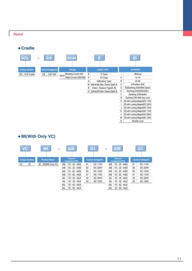
VCL
VC
Cradle TYPE
E E ClassF F2 ClassG G(Bushing Type)M Metal Shutter Direct - Drawout Type(K, B)B Direct - Drawout Type(K, B)H Earthing S/W Direct - Drawout Type(K, B)
Vacuum Contactor(VCI)
32E VC - 3Z - 42EE34E VC - 3Z - 44EE62E VC - 6Z - 42EE64E VC - 6Z - 44EE32L VC - 3Z - 42LE34L VC - 3Z - 44LE62L VC - 6Z - 42LE64L VC - 6Z - 44LE
Product Name
MI MI(With Only VC)
Control Voltage(V)
D1 DC 110VD2 DC 220VD3 DC 125VA1 AC 110VA2 AC 220VA3 AC 125V
Vacuum Contactor(VC2)
32E VC - 3Z - 42EE34E VC - 3Z - 44EE62E VC - 6Z - 42EE64E VC - 6Z - 44EE32L VC - 3Z - 42LE34L VC - 3Z - 44LE62L VC - 6Z - 42LE64L VC - 6Z - 44LE
Control Voltage(V)
D1 DC 110VD2 DC 220VD3 DC 125VA1 AC 110VA2 AC 220VA3 AC 125V
Ratings
42/44Breaking Current 4kARated Current 200/400A
Accessory
- WithoutA 1a 1bB 2a 2bC 3 Position S/WD ES(Earthing S/W)With OptionE Earthing S/W(2NO2NC)F Earthing S/W(4a4b)G Earthing S/W With Key LockH ES with Locking Magnet(DC 110V)I ES with Locking Magnet(DC 220V)J ES with Locking Magnet(DC 125V)K ES with Locking Magnet(AC 110V)L ES with Locking Magnet(AC 220V)M ES with Locking Magnet(AC 125V)N Shutter Lock
Unique Symbol
VCL VCS Cradle
Unique Symbol
VC VC
Rated Voltage(kV)
3/6 3.6/7.2kV
■Cradle
■MI(With Only VC)
3/6
MI
E
D1 D1
EI
62E62E
42/44
11

External View
Combination Drawout Type
Combination Direct - Drawout Type
E - Class Cradle
M - Class Cradle
F - Class Cradle
B - Class Cradle
Front Cover
Fuse Checking Window
Auxiliary Switch
ON/OFF Indicator
Operation Counter
Manual Trip Button
Drawout Carrier
Direct - Drawout Carrier
Drawout Handle
Interlock Lever
Hole for Interlock Lever Insertion
TEST/RUN Indicator
Cradle
Fuse Case
Shutter
12
Safety components
1 2 3 4 5 6
7 8 9 10 11 12
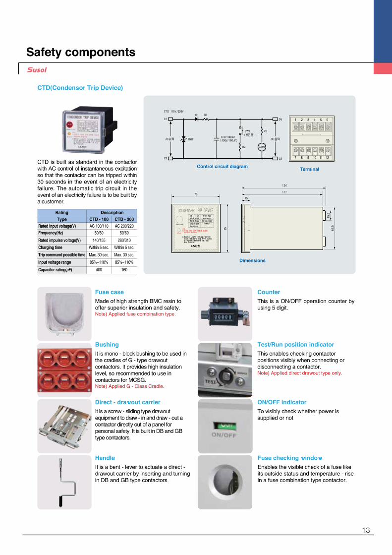
Rating DescriptionType CTD - 100 CTD - 200
Rated input voltage(V) AC 100/110 AC 200/220Frequency(Hz) 50/60 50/60
Rated impulse voltage(V) 140/155 280/310
Charging time Within 5 sec. Within 5 sec.
Trip command possible time Max. 30 sec. Max. 30 sec.
Input voltage range 85%~110% 85%~110%
Capacitor rating(μF) 400 160
CTD is built as standard in the contactor with AC control of instantaneous excitation so that the contactor can be tripped within 30 seconds in the event of an electricity failure. The automatic trip circuit in the event of an electricity failure is to be built by a customer.
Dimensions
Control circuit diagram Terminal
CTD(Condensor Trip Device)
HandleIt is a bent - lever to actuate a direct - drawout carrier by inserting and turning in DB and GB type contactors
Fuse checking windowEnables the visible check of a fuse like its outside status and temperature - rise in a fuse combination type contactor.
ON/OFF indicatorTo visibly check whether power is supplied or not
CounterThis is a ON/OFF operation counter by using 5 digit.
Test/Run position indicatorThis enables checking contactor positions visibly when connecting or disconnecting a contactor.Note) Applied direct drawout type only.
Fuse caseMade of high strength BMC resin to offer superior insulation and safety.Note) Applied fuse combination type.
BushingIt is mono - block bushing to be used in the cradles of G - type drawout contactors. It provides high insulation level, so recommended to use in contactors for MCSG. Note) Applied G - Class Cradle.
Direct - drawout carrierIt is a screw - sliding type drawout equipment to draw - in and draw - out a contactor directly out of a panel for personal safety. It is built in DB and GB type contactors.
13

Main contact partConsists of vacuum interrupters, main terminals and moving shunts that are supported by a one - moulded frame that maintains insulation between phases. Vacuum interrupters are operated by means of the actuating mechanism that is connected to movable parts of a vacuum interrupter with a insulation rod.
Actuating mechanismDesigned simply without any linkage to be suited for frequent - operation and long service life. The actuating lever connected to a moving core of a actuating magnet that carrys out the function of a actuating shaft moves up and down to control the contact pressure for stable operations.
Control methodContinuous excitation - �During a contactor is closed the control coil is required to
be excited continuously to pul l the moving core magnetically. In case of discontinuing the control power the moving core is to be returned by a spring because of the disappearance of magnetic force, which causes the opening of a contactor.
Instantaneous excitation - �In this method the continuous exciting of a control coil to maintain the closing of a contactor is not required as the latch built in it holds the mechanism. In case of manual tripping, a contactor will be tripped by releasing the latch when turn on the manual trip button.
Latch mechanism
Line terminal
Insulation mold frame
Load terminal
Shunt
Control coil
Return spring
Spring guide Spring spacer
Protection cover
Vacuum interrupter
Insulation rod
Contact springActuating lever
Fixed core
Moving core
Main contact part
Internal structure
Type Control method "Control voltage (V)"
"Closing current(A) / time(ms)"
"Trip current(A) / time(ms)"
"Holding current(A) / time(ms)"
VC - 3/6 - 42/44 - E/L
Continuous Excitation(E)
DC/AC 110V 3/100 - 0.6/40DC/AC 125V 3/100 - 0.6/40DC/AC 220V 2/100 - 0.6/40
Instantaneous Excitation(L)
DC/AC 110V 5/100 3/35 - DC/AC 125V 5/100 3/35 - DC/AC 220V 10/100 6/35 -
Instantaneous Excitation(L)(With CTD)
AC 110V 5/100 5/35 - AC 125V 5/100 5/35 - AC 220V 10/100 10/35 -
14

FeaturesVacuum interruptersIn the closed position, normal current flows through the interrupter. When a fault occur and interruption is required, the contacts are quickly separated. The are which is oriented between surfaces of contact shall diffuse at the contact structure of flat shape. It prevents local heating and damage. The arc burns in an ionized metal vapor, which condenses on the surrounding metal shield.The arc is extinguished and vapor production is ceased at current zero. The metal vapor plasma is very rapidly dispersed, cooled, recombined, and deionized, and the metal vapor products are quickly condensed so that the contacts withstand the transient recovery voltage.
LS vacuum interrupters consists of spiral contact, the material of which is CuCr to provide a long service life and
high withstand voltage characteristic.
Voltage phenomena
(i) Arc re-ignition(ii)Restrikes(iii) B.I.L(iv) A.C.voltage withstand
(i) Weld(ii) Bridge explosion
(i) Contact jets(ii) Shield involvement
(i) Arc instability(ii) Interruption
Current zeroArc initiation High current arc mode
Time (ms) Time (㎲)Fault
current
Recovery voltage
Moving electrode
Moving electrode terminal
Bellows
Bellows shield
Ceramic
Arc shield
Contact Fixed electrode terminal
Fixed electrode
Internal structureExternal view
Fixed electrode
Dimensions
AC arcing and interruption phenomena in vacuum
RatingsRated voltage (kV) 7.2
Rated current (A) 400
Rated interrupting current (kA) 4.5
Contact stroke (mm) 4.75
Opening speed average (m/s) 0.6
Closing speed average (m/s) 0.3
Contact force (kg) 7 Min
Moving side weight (kg) 0.23
Interrupter weight (kg) 0.52
Max. contact erosion (mm) 1
Vacuum interrupters
15
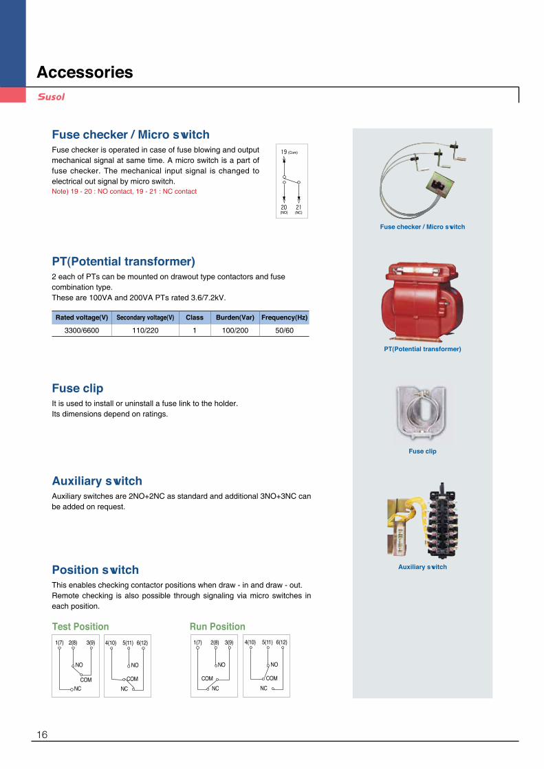
Fuse checker / Micro switch
PT(Potential transformer)
Fuse clip
Auxiliary switch
Fuse checker / Micro switchFuse checker is operated in case of fuse blowing and output mechanical signal at same time. A micro switch is a part of fuse checker. The mechanical input signal is changed to electrical out signal by micro switch.Note) 19 - 20 : NO contact, 19 - 21 : NC contact
PT(Potential transformer)2 each of PTs can be mounted on drawout type contactors and fuse combination type. These are 100VA and 200VA PTs rated 3.6/7.2kV.
Fuse clipIt is used to install or uninstall a fuse link to the holder. Its dimensions depend on ratings.
Auxiliary switchAuxiliary switches are 2NO+2NC as standard and additional 3NO+3NC can be added on request.
Position switchThis enables checking contactor positions when draw - in and draw - out. Remote checking is also possible through signaling via micro switches in each position.
(Com)
(NO) (NC)
Run PositionTest Position
Accessories
Rated voltage(V) Secondary voltage(V) Class Burden(Var) Frequency(Hz)
3300/6600 110/220 1 100/200 50/60
16
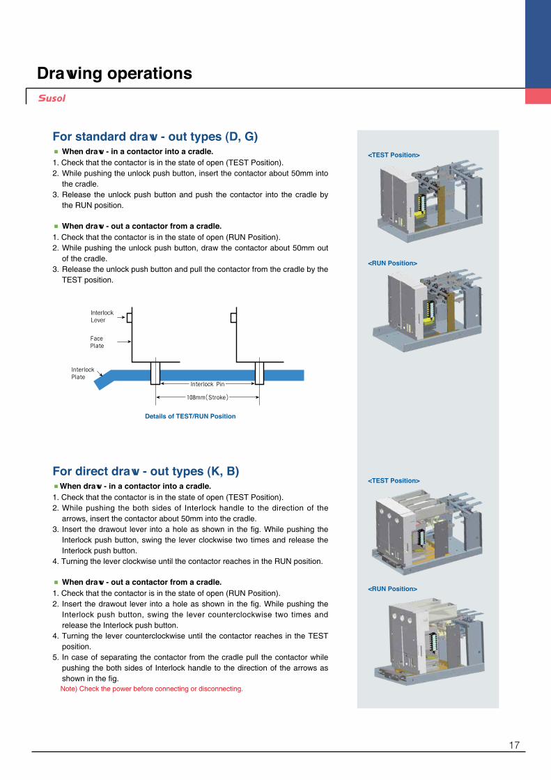
Details of TEST/RUN Position
For standard draw - out types (D, G)■ When draw - in a contactor into a cradle.1. Check that the contactor is in the state of open (TEST Position).2. �While pushing the unlock push button, insert the contactor about 50mm into
the cradle.3. �Release the unlock push button and push the contactor into the cradle by
the RUN position.
■ When draw - out a contactor from a cradle.1. Check that the contactor is in the state of open (RUN Position).2. �While pushing the unlock push button, draw the contactor about 50mm out
of the cradle.3. �Release the unlock push button and pull the contactor from the cradle by the
TEST position.
For direct draw - out types (K, B)■When draw - in a contactor into a cradle.1. Check that the contactor is in the state of open (TEST Position).2. �While pushing the both sides of Interlock handle to the direction of the
arrows, insert the contactor about 50mm into the cradle.3. �Insert the drawout lever into a hole as shown in the fig. While pushing the
Interlock push button, swing the lever clockwise two times and release the Interlock push button.
4. Turning the lever clockwise until the contactor reaches in the RUN position.
■ When draw - out a contactor from a cradle.1. Check that the contactor is in the state of open (RUN Position).2. �Insert the drawout lever into a hole as shown in the fig. While pushing the
Interlock push button, swing the lever counterclockwise two times and release the Interlock push button.
4. �Turning the lever counterclockwise until the contactor reaches in the TEST position.
5. �In case of separating the contactor from the cradle pull the contactor while pushing the both sides of Interlock handle to the direction of the arrows as shown in the fig.Note) Check the power before connecting or disconnecting.
Drawing operations
<TEST Position>
<RUN Position>
<TEST Position>
<RUN Position>
17
Auxiliary Device
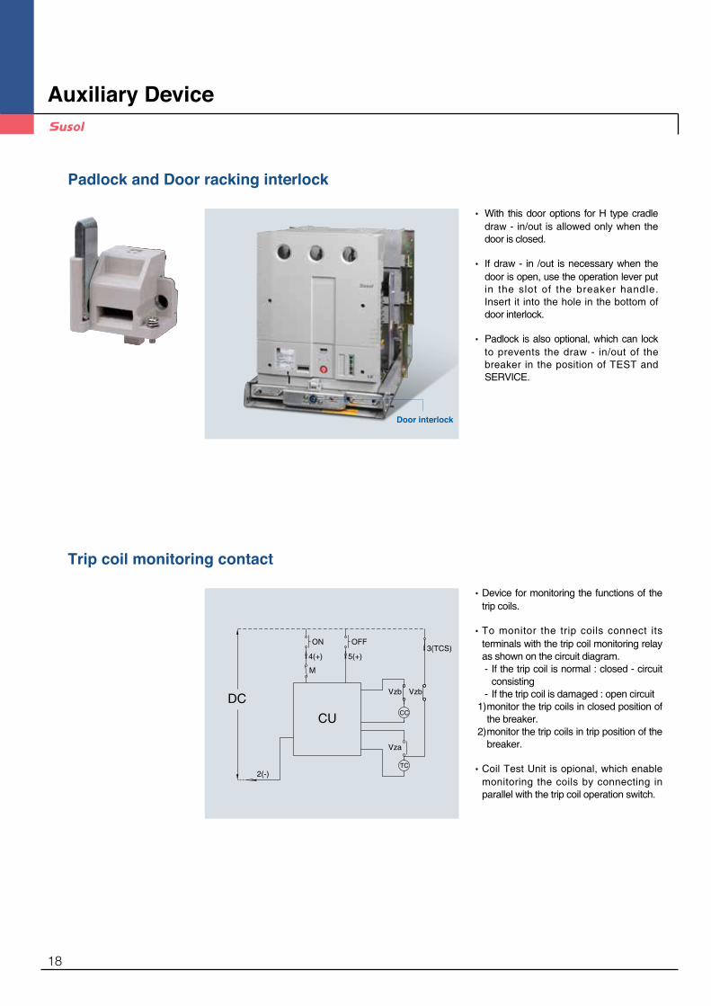
Padlock and Door racking interlock
Trip coil monitoring contact
• �With this door options for H type cradle draw - in/out is allowed only when the door is closed.
• �If draw - in /out is necessary when the door is open, use the operation lever put in the slot of the breaker handle. Insert it into the hole in the bottom of door interlock.
• �Padlock is also optional, which can lock to prevents the draw - in/out of the breaker in the position of TEST and SERVICE.
Door interlock
• �Device for monitoring the functions of the trip coils.
• �To monitor the trip coils connect its terminals with the trip coil monitoring relay as shown on the circuit diagram.
- �If the trip coil is normal : closed - circuit consisting
- �If the trip coil is damaged : open circuit 1) �monitor the trip coils in closed position of
the breaker. 2) �monitor the trip coils in trip position of the
breaker.
• �Coil Test Unit is opional, which enable monitoring the coils by connecting in parallel with the trip coil operation switch.
M
CCCU
ON
4(+)
OFF
5(+)
Vzb
Vza
TC2(-)
Vzb
3(TCS)
DC
18

Push Bar
• �It is a protection cover to prevent an acc ident due to un in tended operation of ON/OFF button.
• �Use the push - bar to operate the ON/OFF button.
• �It is to prevent manual operation of ON/OFF button due to user’s wrong handling.
• �It is not possible to handle ON/OFF operation under the “Button lock” status.
* �Key lock is not supplied.
Button Cover
Button Padlock
Earthing Switch
• �For the safety during the maintenance of switchgear in the position of TEST/Drawout discharge the charging current in the load side of a VCB with this earthing switch. It is available only for K,B type Earthing Truck.
* �Regarding the operations of earthing switch and related accessories see the instruction manual.
* ��Applicable Standards : IEC 62271 - 102
Earthing Switch
19

• �In case of using earthing switch it can be added for two types of interlocking. 1) Interlock to keep opening 2) Interlock to keep earthing
Earthing Switch Keylock
Locking Magnet for Earthing Switch
• �In case of using earthing switch it can be added to prevent the earthing switch from opening or earthing before it is energized.
• �Verify if the locking magnet is energized before opening or earthing the earthing switch.
• �Control voltage - �DC 24V / DC 48V / DC 110V / DC 125V / DC 220V - �AC 48V / AC 110V / AC 220V
ES용 Locking magnet
Keylock for Earthing Switch
Auxiliary Device
20

CC
8
7
12
11
CC
6
5
2
1110
9
ON/OFF
DC/AC
31
16
12
6
5
4
32
1
1614
1513
1314
15
9
10
CU [Auxiliary:3a3b]7
8Vzb
4
[Auxiliary:2a2b]
1412108
131197
1110
9
12
5
4
32 13
14
7
8CC
CU
ON
4(+)
OFF
5(+)
Vzb
Vza
TC2(-)
Vzb
3(TCS)
DC/AC
[Auxiliary:2a2b]
1412108
131197
1110
9
12
56
4
32
1
1314
15
7
8
2
AC
CTDON
4
Vzb Vza
1
3OFF
5
15
CU
(+) (-)
CC TC
Vzb
6(TCS)
Electrical circuit diagram
Continuous Excitation(DC/AC, 110V~220V): Fixed Type
Instantaneous Excitation(DC/AC, 110V~220V): Fixed Type
Instantaneous Excitation_CTD(AC, 110V~220V): Fixed Type
Apply the power source at terminals of 1 - 2. Switch it using contacts of No.3 - 4 terminal.
When closing : Switch it using a contact of No. 4(+), 2(-) terminalWhen tripping : Switch it using a contact of No. 5(+), 2(-) terminal→ Contactor does not operate when reverse connected
Apply the power source at terminals of 1 - 2When closing : Switch it using contacts of No.3, 4 terminalWhen tripping : Switch it using contacts of No.5, 15 terminal
•CU : Control Unit•CC : Closing Coil•VZb : Auxiliary Switchs Contact "b"
•CU : Control Unit•CC : Closing Coil•TC : Tripping Coil•VZb : Auxiliary Switchs Contact "b"•VZa : Auxiliary Switchs Contact "a"
•CU : Control Unit•CC : Closing Coil•VZb : Auxiliary Switchs Contact "b"
21
8
7
12
11
6
5 9
10
[Auxiliary:2a2b]
21
19
20
[FUSE CHECKER]
CCCC2
ON/OFF
VzbDC/AC
31
CU
<주회로>
4
M
181617
R S T
1110
9
16
12
6
5
4
32
1
7
8
2120
19
17
18
10
9
14
13
8
7 11
12
[Auxiliary:2a2b]
21
19
20
[FUSE CHECKER]
<주회로>
181617
R S T
1110
9
16
12
5
4
214313
7
8
2120
19
17
18
M
CCCU
ON
4(+)
OFF
5(+)
Vzb
Vza
TC2(-)
Vzb
3(TCS)
DC/AC
10
9
14
13
8
7 11
12
[Auxiliary:2a2b]
21
19
20
[FUSE CHECKER]
<주회로>
181617
R S T
1110
9
16
12
5
6
4
2
15
14
1
313
7
8
2120
19
17
18
M
2
AC
CTDON
4
1
3OFF
5
15
CU
(+) (-)
Vzb Vza
CC TC
Vzb
6(TCS)
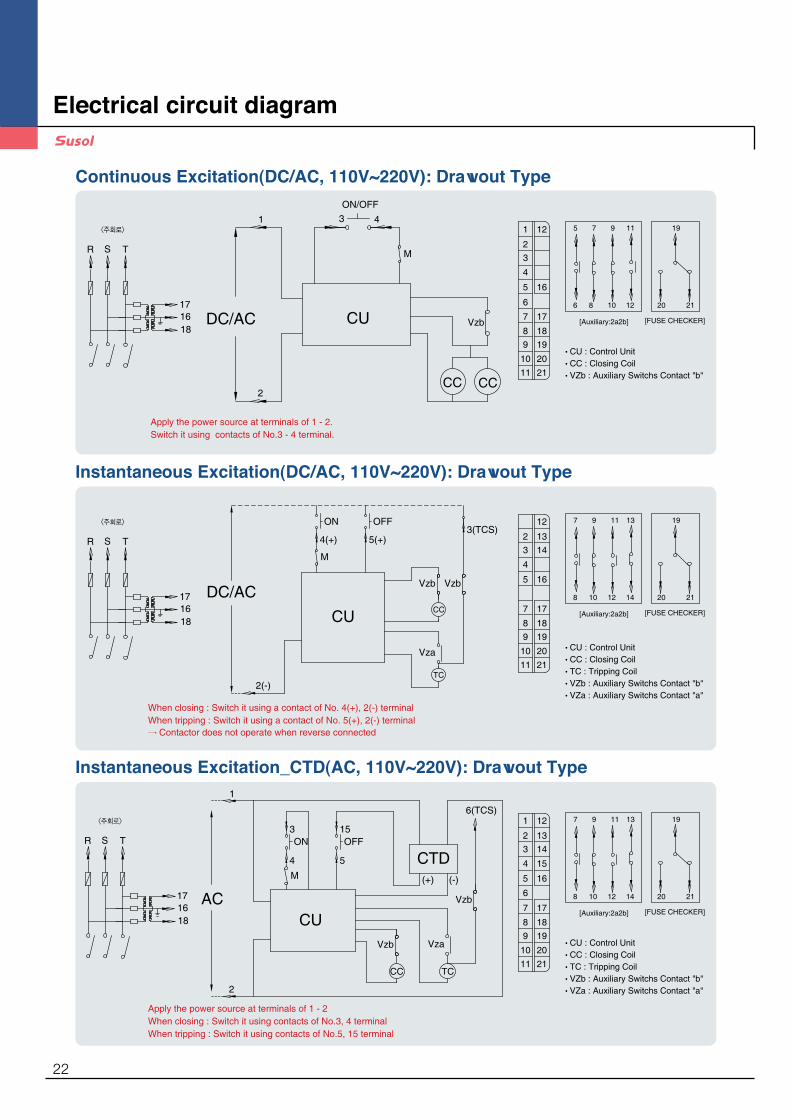
Continuous Excitation(DC/AC, 110V~220V): Drawout Type
Instantaneous Excitation(DC/AC, 110V~220V): Drawout Type
Instantaneous Excitation_CTD(AC, 110V~220V): Drawout Type
Apply the power source at terminals of 1 - 2. Switch it using contacts of No.3 - 4 terminal.
When closing : Switch it using a contact of No. 4(+), 2(-) terminalWhen tripping : Switch it using a contact of No. 5(+), 2(-) terminal→ Contactor does not operate when reverse connected
Apply the power source at terminals of 1 - 2When closing : Switch it using contacts of No.3, 4 terminalWhen tripping : Switch it using contacts of No.5, 15 terminal
•CU : Control Unit•CC : Closing Coil•VZb : Auxiliary Switchs Contact "b"
•CU : Control Unit•CC : Closing Coil•TC : Tripping Coil•VZb : Auxiliary Switchs Contact "b"•VZa : Auxiliary Switchs Contact "a"
•CU : Control Unit•CC : Closing Coil•TC : Tripping Coil•VZb : Auxiliary Switchs Contact "b"•VZa : Auxiliary Switchs Contact "a"
Electrical circuit diagram
22
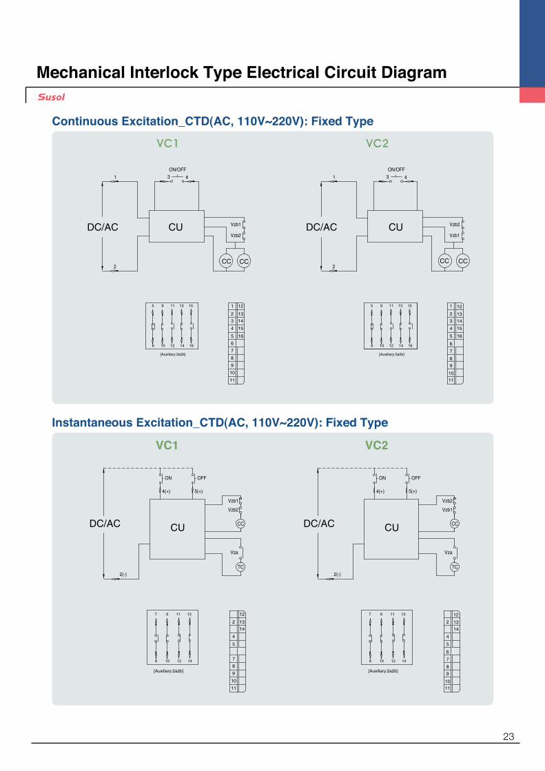
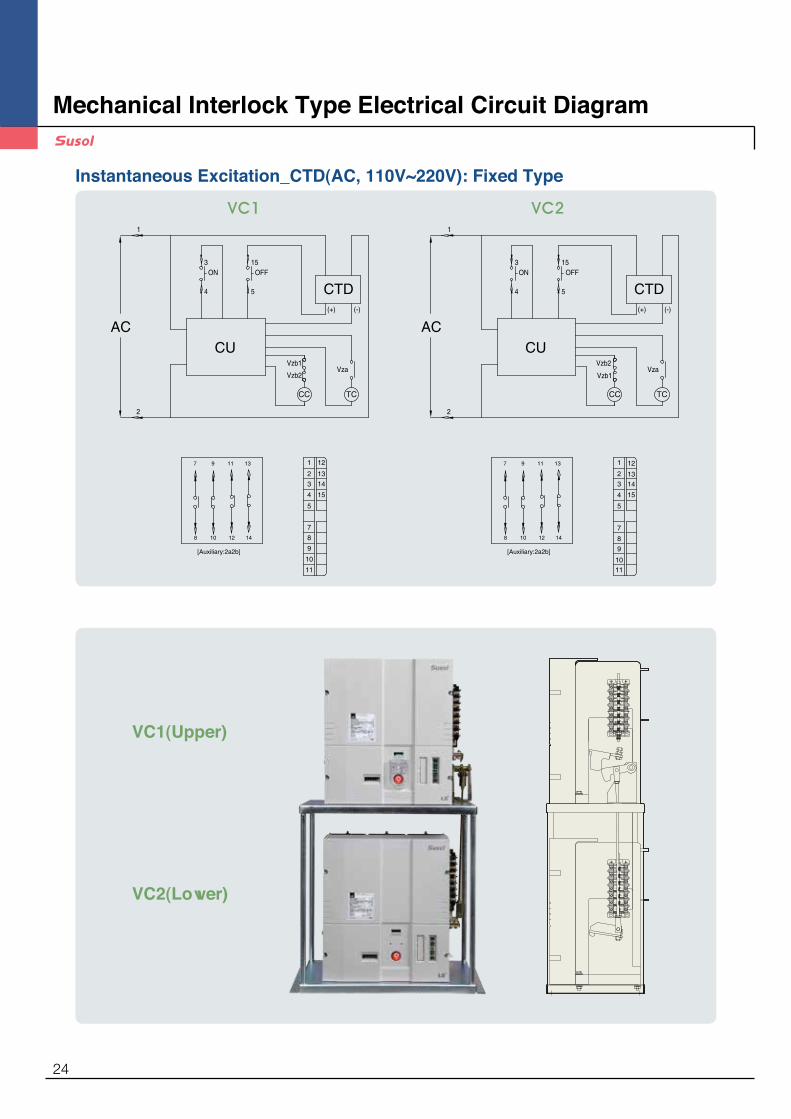
Mechanical Interlock Type Electrical Circuit Diagram
CCCC2
ON/OFF
Vzb2DC/AC
31
CUVzb1
4
1110
9
16
12
6
5
4
32
1
1314
15
7
8
6
5
12
11
1614
15139
10
[Auxiliary:3a2b]
CCCC2
ON/OFF
Vzb1DC/AC
31
CUVzb2
4
11
10
9
16
12
6
5
4
32
1
1314
15
78
6
5
12
11
1614
15139
10
[Auxiliary:3a2b]
DC/AC CCCU
ON
4(+)
Vzb1
OFF
5(+)
Vza
TC2(-)
Vzb2
8
7
1412
13119
10
[Auxiliary:2a2b]
DC/AC CCCU
ON
4(+)
Vzb2
OFF
5(+)
Vza
TC2(-)
Vzb1
8
7
1412
13119
10
[Auxiliary:2a2b]
1110
9
12
6
5
4
2 1314
7
8
11
10
9
12
5
4
2 1314
7
8
Continuous Excitation_CTD(AC, 110V~220V): Fixed Type
Instantaneous Excitation_CTD(AC, 110V~220V): Fixed Type
VC1 VC2
VC1 VC2
23
2
AC
CTDON
4
Vzb2
Vzb1Vza
1
3OFF
5
15
CU
(+) (-)
CC TC
8
7
1412
13119
10
[Auxiliary:2a2b]
2
AC
CTDON
4
Vzb1Vza
1
3OFF
5
15
CU
(+) (-)
CC TC
Vzb2
8
7
1412
13119
10
[Auxiliary:2a2b]
1110
9
12
5
4
32
1
1314
15
7
8
11
10
9
12
5
4
32
1
1314
15
78
Instantaneous Excitation_CTD(AC, 110V~220V): Fixed Type
VC1 VC2
VC1(Upper)
VC2(Lower)
188
19
11
10
9
21
20
17
16
15
14
13
121
6
5
4
3
2
7
28
31
30
29
33
3222
26
25
24
23
27
188
19
11
10
9
21
20
17
16
15
14
13
121
6
5
4
3
2
7
28
31
30
29
33
3222
26
25
24
23
27
1222
1626
1525
1121
1727
1121
1727
14
15
16
25
24
26
1323
24 14
1323
Mechanical Interlock Type Electrical Circuit Diagram
24

External Dimensions
385(Terminal Hole)
119 119
18819
1110
9
2120
17
161514
13121
6
543
2
728
3130
29
333222
262524
23
27
OFFO
240415
353
398.
620
.5115(Terminal Hole)
32
20
Ø11(Terminal Hole)
247
274.5
255
136.
5
110
4-Ø9(Mounting Hole)
440
570.2
309
316
565
119 119
OFFO
506.5
31
160
469
494
119 119
OFFO
440
565
518
494
570.2
160
309
518.3
335 31
(Unit : mm)
VC - 3/6Z - 42/44E(L)E
VC - 3/6D - 42/44E(L)E
VC - 3/6K - 42/44E(L)E
Fixed Type
Drawout Type
Direct - Drawout Type
25

119 119
OFFO
453
473
599
440
32
20
Ø11(Terminal Hole)
485.1
277.
916
0
543
316 31
4-Ø9(Terminal Hole)
(Unit : mm)
VC - 3/6F - 42/44E(L)E
570.2
31
506.5
160
309
316
OOFF
609
119 119
469
440
494
VC - 3/6G - 42/44E(L)E
OFFO
119 119
440
609
494
518
309
160
570.2
335 31
518.3
VC - 3/6B - 42/44E(L)E
Combination Drawout Type
Combination Direct - Drawout Type
Combination Fixed Type
* ���In case of applying 6M - 300/400, 543mm changes 613mm
* ���In case of applying 6M - 300/400, 570.2mm changes 640.2mm
* ���In case of applying 6M - 300/400, 570.2mm changes 640.2mm
External Dimensions
26
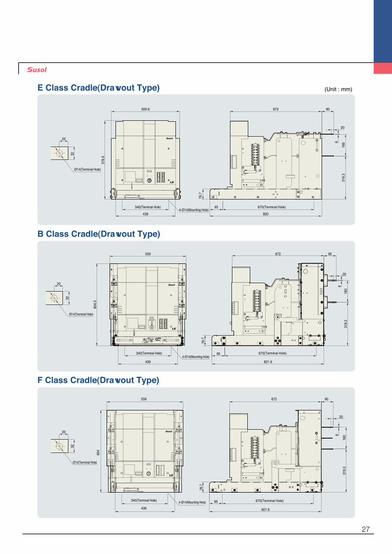
6
95
OFFOOFFO
500.6
576.
9
672
20
90
160
319.
3
439 820
76.7
32
20
670(Terminal Hole)4-Ø14(Mounting Hole)
340(Terminal Hole)
Ø14(Terminal Hole)
95
821.6
76.7
4-Ø14(Mounting Hole)
6
OFFO
559
604.
3
319.
316
0
672
20
90
340(Terminal Hole)
439
670(Terminal Hole)
32
20
Ø14(Terminal Hole)
76.7
821.6
670(Terminal Hole)95
6
20
160
319.
3
OFFO
559
604
340(Terminal Hole)
439
672 90
4-Ø14(Mounting Hole)
32
20
Ø14(Terminal Hole)
E Class Cradle(Drawout Type)
B Class Cradle(Drawout Type)
F Class Cradle(Drawout Type)
(Unit : mm)
27

76.7
6
160
319.
3
821.6
95
OFFO
604
559
439
672 90
32
20
670(Terminal Hole)340(Terminal Hole) 4-Ø14(Mounting Hole)
Ø14(Terminal Hole)
20
4-Ø14(Mounting Hole)
20
6
90
95
821.6
670(Terminal Hole)
76.7
OFFO
160
610
672557
439
340(Terminal Hole)
319.
3
32
20
Ø14(Terminal Hole)
6
OFFO
559
784.
3
684(Terminal Hole)
734
180.
8
672 90
160
319.
317
8.5
754.6
861.3
20
500.1(Terminal Hole)638.5 87.3
32
20
Ø14(Terminal Hole)
4-Ø14(Mounting Hole)
M Class Cradle(Drawout Type)
H Class Cradle(Drawout Type)
G Class Cradle(Drawout Type) (Unit : mm)
External Dimensions
28
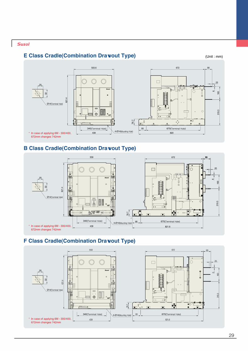
6
670(Terminal Hole)954-Ø14(Mounting Hole)
OFFO
32
20
Ø14(Terminal Hole)
672
20
90
160
319.
3
340(Terminal Hole)
439
500.662
1.4
82076
.7
OFFO
20
6
95
821.6
670(Terminal Hole)4-Ø14(Mounting Hole)
160
319.
3
672 90559
621.
4
439
340(Terminal Hole)
76.7
90
32
20
Ø14(Terminal Hole)
1606
319.
3
20
95
76.7
670(Terminal Hole)
821.6
90
OFFO
672559
621.4
340(Terminal Hole)
439
32
20
Ø14(Terminal Hole)
4-Ø14(Mounting Hole)
E Class Cradle(Combination Drawout Type)
B Class Cradle(Combination Drawout Type)
F Class Cradle(Combination Drawout Type)
* ����In case of applying 6M - 300/400, 672mm changes 742mm
* ����In case of applying 6M - 300/400, 672mm changes 742mm
* ����In case of applying 6M - 300/400, 672mm changes 742mm
(Unit : mm)
29
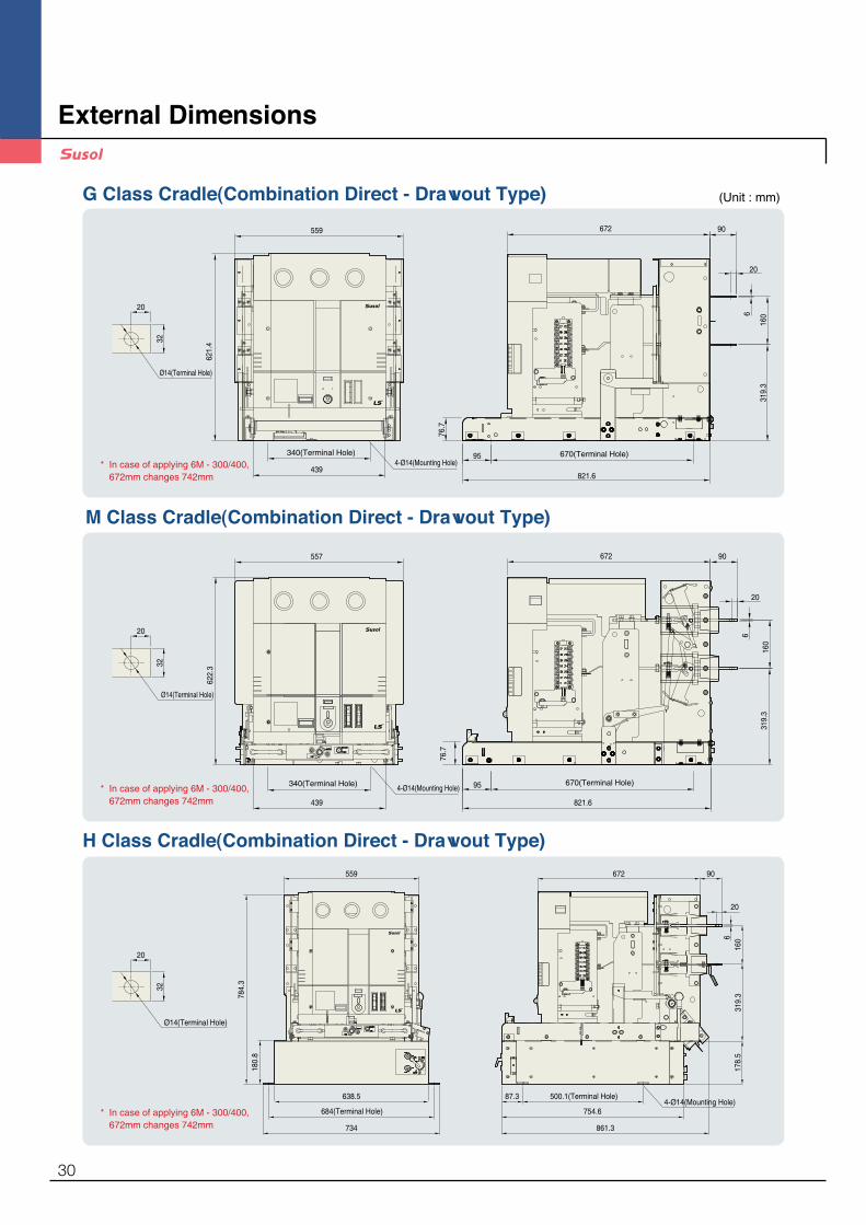
6
20
319.
316
0
95
76.7
670(Terminal Hole)
821.6
OFFO
621.
4
559 90672
340(Terminal Hole)
4394-Ø14(Mounting Hole)
32
20
Ø14(Terminal Hole)
4-Ø14(Mounting Hole)
20
6
95 670(Terminal Hole)
76.7
OFFO
160
319.
3
622.
3
340(Terminal Hole)
439
90672557
821.6
32
20
Ø14(Terminal Hole)
4-Ø14(Mounting Hole)
OFFO
6
559
784.
3
684(Terminal Hole)
734
180.
8
638.5
672 90
160
319.
317
8.5
754.6
861.3
20
500.1(Terminal Hole)87.3
32
20
Ø14(Terminal Hole)
M Class Cradle(Combination Direct - Drawout Type)
H Class Cradle(Combination Direct - Drawout Type)
G Class Cradle(Combination Direct - Drawout Type) (Unit : mm)
* �In case of applying 6M - 300/400, 672mm changes 742mm
* �In case of applying 6M - 300/400, 672mm changes 742mm
* �In case of applying 6M - 300/400, 672mm changes 742mm
External Dimensions
30

188
19
11
10
9
21
20
17
16
15
14
13
121
6
5
4
3
2
7
28
31
30
29
33
3222
26
25
24
23
27
188
19
11
10
9
21
20
17
16
15
14
13
121
6
5
4
3
2
7
28
31
30
29
33
3222
26
25
24
23
27
1222
1626
1525
1121
1727
32
20
Ø11(Terminal Hole)
516(Terminal Hole)
540
495
423.
6
240(Terminal Hole)
270
255.
513
7.5
255.
513
7.5
918.
6
4-Ø11(Mounting Hole)
247
270.4
1121
1727
14
15
16
25
24
26
1323
24 14
1323
Mechanical Interlock Type (Unit : mm)
31

Power fuseLS Prime - MEC power fuses are designed to protect equipments from fault current such as short - circuit, and generally used for the protection the circuits of transformers, capacitors and motors they protect.
For further safety and reliability the elements inside of fuses are made of silver, and high quality quartzs and and ceramic are used for magnetic rods and tubes, respectively.
LS medium voltage vacuum contactors using LS vacuum interrupters manufactured with worldclass technology are type tested in LS PT & T that is accredited high power test lab by worldclass KOLAS. To ensure the performance they, installed in a vacuum contactor, are tested according to IEC 60282 - 1 in LS PT & T that is accredited high power test lab by worldclass KOLAS.
Considerations in application• �Power fuses are suitable for the protection from a short - circuit, Overload current will not
protected.• �Reset or re - use after blowing is not possible. Fuse reset or re - use is not possible after
fused are blown out.• �When the fuses are selected, the inrush currents arising from the starting transformers,
motors, capacitors should be considered.• �When the fuses are selected, their usage and circuit requirements should be considered.• �For the purpose of protection from the fault current below the lowest interrupting current
of the fuse it is desirable to replace it with a fuse having lower interrupting rate or add other overcurrent relay in series
• �Withstand voltage of the circuit should be higher than that of a fuse that protects it.• �If possible, select the fuse whose rated current is much higher than the load current. The
rated current not sufficiently exceeding the normal current of the load may cause reduction in the service life.
• �Replace all three fuses in case of blowing in a fuse.
Determination of the rated currentThe rated current of the fuse must be selected properly after examination of the current/time characteristics of fuses, equipments and the related circuit conditions.
General considerations • �When the fuses are selected the sufficient rated current should be considered to avoid
the deterioration of the fuse element due to sustained load current in the long term.• �The fuse rated current should be higher than the sum of all load currents.• �The estimated overload current should be within the fuse's time/current characteristics.
The estimated overload current should not exceed the allowable overload withstand currents of the equipment and the number of its events should not exceed 100 times.
• �The characteristic curve of a fuse must lie to the right of those of other equipments to be protected.
• �The withstand strength such as permissible let - through current, I²t of the equipments to be protected must be higher than that of a fuse.
• �Coordination of permissible time limit Protection equipments in the line side < Fuses < Protection equipments in the load side
• �Coordination when fuses are used as back - up protection Permissible let - through current of a fuse < That of a protection equipment• �Use the same rating for all three phases even the differential current between phases
exists.
KERI(24kV)
Power fuse
32
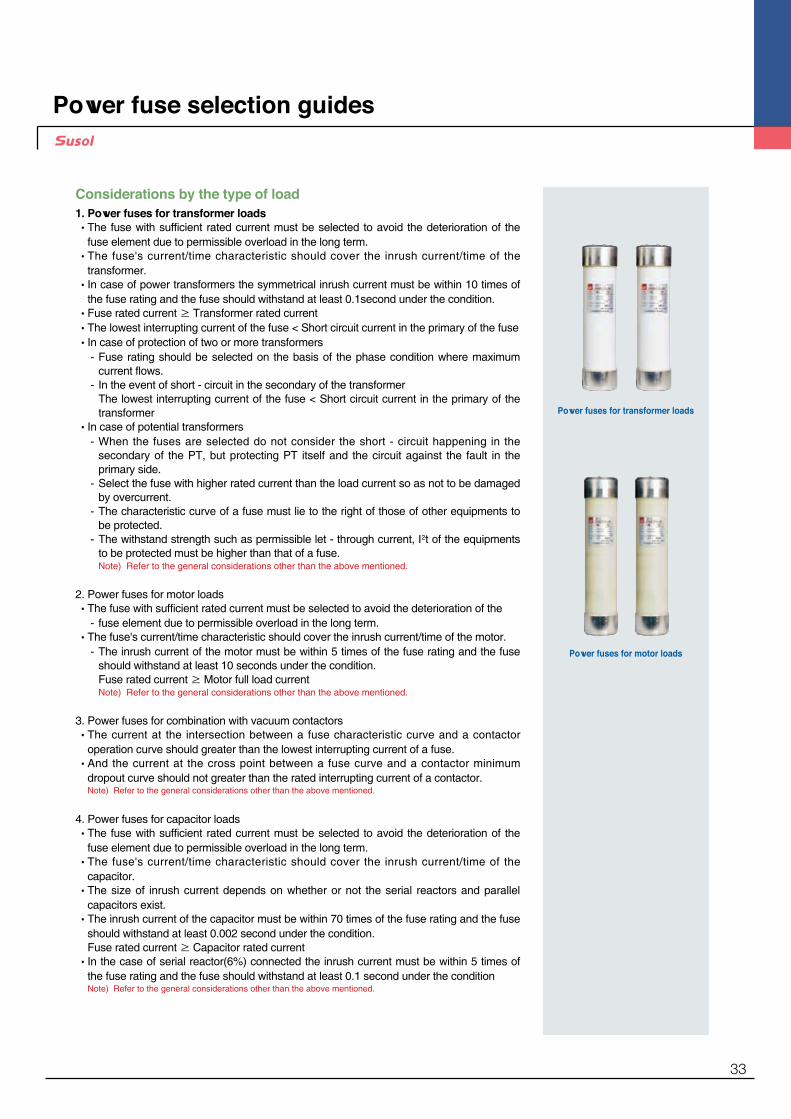
Considerations by the type of load1. Power fuses for transformer loads • �The fuse with sufficient rated current must be selected to avoid the deterioration of the
fuse element due to permissible overload in the long term. • �The fuse's current/time characteristic should cover the inrush current/time of the
transformer. • �In case of power transformers the symmetrical inrush current must be within 10 times of
the fuse rating and the fuse should withstand at least 0.1second under the condition. • �Fuse rated current ≥ Transformer rated current • �The lowest interrupting current of the fuse < Short circuit current in the primary of the fuse • �In case of protection of two or more transformers - �Fuse rating should be selected on the basis of the phase condition where maximum
current flows. - �In the event of short - circuit in the secondary of the transformer
The lowest interrupting current of the fuse < Short circuit current in the primary of the transformer
• �In case of potential transformers - �When the fuses are selected do not consider the short - circuit happening in the
secondary of the PT, but protecting PT itself and the circuit against the fault in the primary side.
- �Select the fuse with higher rated current than the load current so as not to be damaged by overcurrent.
- �The characteristic curve of a fuse must lie to the right of those of other equipments to be protected.
- �The withstand strength such as permissible let - through current, I²t of the equipments to be protected must be higher than that of a fuse.
Note) Refer to the general considerations other than the above mentioned.
2. Power fuses for motor loads • �The fuse with sufficient rated current must be selected to avoid the deterioration of the - �fuse element due to permissible overload in the long term. • ��The fuse's current/time characteristic should cover the inrush current/time of the motor. - ��The inrush current of the motor must be within 5 times of the fuse rating and the fuse
should withstand at least 10 seconds under the condition. Fuse rated current ≥ Motor full load current
Note) Refer to the general considerations other than the above mentioned.
3. Power fuses for combination with vacuum contactors • ��The current at the intersection between a fuse characteristic curve and a contactor
operation curve should greater than the lowest interrupting current of a fuse. • ��And the current at the cross point between a fuse curve and a contactor minimum
dropout curve should not greater than the rated interrupting current of a contactor. Note) Refer to the general considerations other than the above mentioned.
4. Power fuses for capacitor loads • ��The fuse with sufficient rated current must be selected to avoid the deterioration of the
fuse element due to permissible overload in the long term. • ��The fuse's current/time characteristic should cover the inrush current/time of the
capacitor. • ��The size of inrush current depends on whether or not the serial reactors and parallel
capacitors exist. • ��The inrush current of the capacitor must be within 70 times of the fuse rating and the fuse
should withstand at least 0.002 second under the condition. Fuse rated current ≥ Capacitor rated current • ��In the case of serial reactor(6%) connected the inrush current must be within 5 times of
the fuse rating and the fuse should withstand at least 0.1 second under the condition Note) Refer to the general considerations other than the above mentioned.
Power fuses for transformer loads
Power fuses for motor loads
Power fuse selection guides
33
Selection tables
DIN type
Application Fuse link Fuse selection by load Fuse selection by load Dimensions(mm)Applicable
holderRated
voltageRated
currentRated
interruptingcurrent
Lowest interrupting
currentTransformer load(kVA) Capacitive
load(kVA) Motor load(kVA)A B C D
Model (kV) (A) (kA) (A) Single phase Three phase Three phase Three phaseLFL - 3/6G 5B
"3.6 (7.2)"
5
40 4In
4 ~ 8 ※ ( 8 ~ 16 ) 6.7 ~ 14 ※ ( 13 ~ 28 ) 9.8up to ※ ( 9.8up to ) 6.5 ~ 10.7 ( 13 ~ 22 )
195 55 - - LFH - 6G - D1HB
LFL - 3/6G 10B 10 6 ~ 13 ( 13 ~ 25 ) 11 ~ 22 ( 21 ~ 44 ) 9.8 ~ 12 ( 19 ~ 24 ) 10.7 ~ 28 ( 22 ~ 36 )LFL - 3/6G 20B 20 15 ~ 31 ( 30 ~ 62 ) 25 ~ 53 ( 51 ~ 107 ) 12 ~ 31 ( 24 ~ 61 ) 28 ~ 57 ( 36 ~ 86 )LFL - 3/6G 30B 30 21 ~ 42 ( 40 ~ 84 ) 35 ~ 73 ( 70 ~ 145 ) 31 ~ 46 ( 61 ~ 92 ) 50 ~ 85 ( 86 ~ 117 )LFL - 3/6G 40B 40 40 ~ 82 ( 80 ~ 165 ) 69 ~ 143 ( 137 ~ 286 ) 46 ~ 64 ( 92 ~ 128 ) 85 ~ 115 (117 ~ 230 )LFL - 3/6G 50B 50 49 ~ 102 ( 98 ~ 204 ) 85 ~ 117 ( 170 ~ 354 ) 64 ~ 81 (128 ~ 163) 115 ~ 142 ( 230 ~ 284 )LFL - 3/6G 60B 63 66 ~ 137 ( 132 ~ 275 ) 114 ~ 238 ( 229 ~ 476 ) 181 ~ 105 (163 ~ 210) 138 ~ 191 ( 276 ~ 382 )
192 77 - - LFL - 3/6G 75B 75 68 ~ 165 ( 134 ~ 330 ) 117 ~ 285 ( 233 ~ 571 ) 105 ~ 150 (210 ~ 300) 181 ~ 252 ( 362 ~ 503 )LFL - 3/6G 100B 100 128 ~ 220 ( 256 ~ 440 ) 222 ~ 381 ( 443 ~ 762 ) 150 ~ 222 (300 ~ 445) 253 ~ 369 ( 469 ~ 739 )LFL - 3/6G 125B 125 151 ~ 275 ( 302 ~ 550 ) 261 ~ 476 ( 522 ~ 952 ) 222 ~ 275 (445 ~ 550) 293 ~ 435 ( 556 ~ 870 )
292 77 - - LFH - 6G - D2HBLFL - 3G - 160B
3.6160 211 ~ 352 ( - ) 365 ~ 610 ( - ) 275 ~ 370 ( - ) 343 ~ 572 ( - )
LFL - 3G - 200B 200 265 ~ 440 ( - ) 495 ~ 762 ( - ) 370 ~ 550 ( - ) 375 ~ 630 ( - )LFL - 6G - 160B
7.2160 265 ~ 440 ( - ) - ( 735~1, 220) - (550 ~ 742) - ( 751 ~ 1,223 )
LFL - 6G - 200B 200 - ( 437 ~ 880 ) - ※ ( 755~1,520) - (742~ 1,000) - (1,154 ~ 1,760 )
DIN type
Application Fuse link Fuse selection by load Fuse selection by load Dimensions(mm)Applicable
holderRated
voltageRated
currentRated
interruptingcurrent
Lowest interrupting
currentTransformer load(kVA) Capacitive
load(kVA) Motor load(kVA)A B C D
Model (kV) (A) (kA) (A) Single phase Three phase Three phase Three phaseLFL - 3/6G - 5 "3.6
(7.2)"5 40 5In - ※ ( 5up to ) 5up to ( 15up to ) - ( - ) -
261 50 47 25 LFH - 6G - D60
LFL - 3/6G - 10 10 10up to ( 15up to ) 15up to ( 30up to ) 10up to ( 25up to ) - LFL - 3/6G - 20 20 20up to ( 50up to ) 30up to ( 75up to ) 30up to ( 50up to ) - LFL - 3/6G - 30 30 30up to ( 75up to ) 75up to ( 150up to ) 50up to ( 100up to ) - LFL - 3/6G - 40 40 50up to ( 100up to ) 100up to ( 200up to ) 75up to ( 150up to ) - LFL - 3/6G - 50 50 75up to ( 150up to ) 150up to ( 300up to ) 100up to ( 200up to ) - LFL - 3/6G - 60 63 - ( - ) - ( - ) - ( - ) - LFL - 3/6G - 75 75 150up to ( 200up to ) 200up to ( 400up to ) 200up to ( 400up to ) -
311 60 57 30 LFH - 6G - D1HLFL - 3/6G - 100 3.6 100 200up to ( 400up to ) 375up to ( 750up to ) 300up to ( 600up to ) - LFL - 3G - 150 150 300up to ( - ) 500up to ( - ) 400up to ( - ) - LFL - 3G - 200 200 400up to ( - ) 750up to ( - ) 600up to ( - ) - LFL - 3G - 300 300 625up to ( - ) 1,000up to ( - ) 1,000up to ( - ) -
311 77 73 43 LFH - 6G - D2HLFL - 3G - 400 7.2 400 750up to ( - ) 1,500up to ( - ) - ( - ) - LFL - 6G - 150 150 - ( 500up to ) - ( 1,000up to ) - ( 800up to ) - LFL - 6G - 200 200 - ( 750up to ) - ( 1,500up to ) - ( 1,200up to ) - LFL - 6G - 300 300 - ( 1,250up to ) - ( 2,000up to ) - ( - ) -
350 110 108 55 LFH - 6G - D4HLFL - 6G - 400 400 - ( - ) - ( 2,500up to ) - ( - ) - LFL - 3M - 20 3.6 20 40 7In - 50up to ※ ( - ) 37 ~ 75 ( - )
200 60 58 30 LFH - 3M - 100LFL - 3M - 50 50 - 150up to ( - ) 90 ~ 200 ( - )LFL - 3M - 100 100 - 300up to ( - ) 220 ~ 400 ( - )LFL - 3M - 150 150 - 400up to ( - ) 450 ~ 630 ( - )
200 77 73 43 LFH - 3M - 200LFL - 3M - 200 200 - 800up to ( - ) 710 ~ 800 ( - )LFL - 3M - 300 300 - 1,000up to ( - ) 900 ~1250 ( - )
250 87 84 50 LFH - 3M - 400LFL - 3M - 400 400 - - ( - ) 1,500 ( - )LFL - 6M - 20 3.6 20 - - ( 100up to ) - ( 75 ~ 160 )
311 60 58 30 LFH - 6M - 50LFL - 6M - 50 50 - - ( 300up to ) - ( 185 ~ 400 )
LFL - 6M - 100 100 - - ( 600up to ) - ( 450 ~ 800 )350 77 73 43 LFH - 6M - 200LFL - 6M - 150 150 - - ( 800up to ) - ( 900 ~ 1,250 )
LFL - 6M - 200 200 - - ( - ) - ( 1,500 )LFL - 6M - 300 300 - - ( - ) - ( 2,500 )
450 87 84 50 LFH - 6M - 400LFL - 6M - 400 400 - - ( - ) - ( 3,000 )
G(General use) type
M(Motor protection) type
34

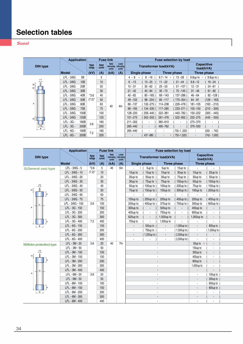
Selecting conditions and warning1. �※ The values in ( ) apply to the loads of 7.2kV.2. �It is assumed that the inrush current of a transformer
is 10 times of the full load current of a motor for 0.1 second.
- �The rated current of a fuse is selected to carry continuously the current of 1.5 times of rated current of a transformer.(1.3 times in the case of ※)
- ���In the transformer load table it is assumed that the interruption will be made at 25 times of rated current within 2 seconds.
3. ��It is assumed that the inrush current of a motor is 5 times of full load current for 10 seconds.
4. �In the case of using the M(motor protection) type fuses for the purpose of the short - circuit protection of a motor or a starter select the proper rating in addition refer to the characteristic curves on the catalog to make the device protected from overload by a circuit breaker or a contactor.
5. ��It is assumed that the inrush current of a capacitor is 71 times of its rated current for 0.002 second.
- �The rated current of a fuse is selected to carry continuously the current of 1.43 times of rated current of a capacitor.
- �In case service life of more than 1000 operations is required select in the M(motor protection) type fuse table.
6. ��The above mentioned comments are according to KS(Korean Industrial Standard) and subject to the real situation.
DIN type
Application Fuse link Fuse selection by load Fuse selection by load Dimensions(mm)Applicable
holderRated
voltageRated
currentRated
interruptingcurrent
Lowest interrupting
currentTransformer load(kVA) Capacitive
load(kVA) Motor load(kVA)A B C D
Model (kV) (A) (kA) (A) Single phase Three phase Three phase Three phaseLFL - 3/6G 5B
"3.6 (7.2)"
5
40 4In
4 ~ 8 ※ ( 8 ~ 16 ) 6.7 ~ 14 ※ ( 13 ~ 28 ) 9.8up to ※ ( 9.8up to ) 6.5 ~ 10.7 ( 13 ~ 22 )
195 55 - - LFH - 6G - D1HB
LFL - 3/6G 10B 10 6 ~ 13 ( 13 ~ 25 ) 11 ~ 22 ( 21 ~ 44 ) 9.8 ~ 12 ( 19 ~ 24 ) 10.7 ~ 28 ( 22 ~ 36 )LFL - 3/6G 20B 20 15 ~ 31 ( 30 ~ 62 ) 25 ~ 53 ( 51 ~ 107 ) 12 ~ 31 ( 24 ~ 61 ) 28 ~ 57 ( 36 ~ 86 )LFL - 3/6G 30B 30 21 ~ 42 ( 40 ~ 84 ) 35 ~ 73 ( 70 ~ 145 ) 31 ~ 46 ( 61 ~ 92 ) 50 ~ 85 ( 86 ~ 117 )LFL - 3/6G 40B 40 40 ~ 82 ( 80 ~ 165 ) 69 ~ 143 ( 137 ~ 286 ) 46 ~ 64 ( 92 ~ 128 ) 85 ~ 115 (117 ~ 230 )LFL - 3/6G 50B 50 49 ~ 102 ( 98 ~ 204 ) 85 ~ 117 ( 170 ~ 354 ) 64 ~ 81 (128 ~ 163) 115 ~ 142 ( 230 ~ 284 )LFL - 3/6G 60B 63 66 ~ 137 ( 132 ~ 275 ) 114 ~ 238 ( 229 ~ 476 ) 181 ~ 105 (163 ~ 210) 138 ~ 191 ( 276 ~ 382 )
192 77 - - LFL - 3/6G 75B 75 68 ~ 165 ( 134 ~ 330 ) 117 ~ 285 ( 233 ~ 571 ) 105 ~ 150 (210 ~ 300) 181 ~ 252 ( 362 ~ 503 )LFL - 3/6G 100B 100 128 ~ 220 ( 256 ~ 440 ) 222 ~ 381 ( 443 ~ 762 ) 150 ~ 222 (300 ~ 445) 253 ~ 369 ( 469 ~ 739 )LFL - 3/6G 125B 125 151 ~ 275 ( 302 ~ 550 ) 261 ~ 476 ( 522 ~ 952 ) 222 ~ 275 (445 ~ 550) 293 ~ 435 ( 556 ~ 870 )
292 77 - - LFH - 6G - D2HBLFL - 3G - 160B
3.6160 211 ~ 352 ( - ) 365 ~ 610 ( - ) 275 ~ 370 ( - ) 343 ~ 572 ( - )
LFL - 3G - 200B 200 265 ~ 440 ( - ) 495 ~ 762 ( - ) 370 ~ 550 ( - ) 375 ~ 630 ( - )LFL - 6G - 160B
7.2160 265 ~ 440 ( - ) - ( 735~1, 220) - (550 ~ 742) - ( 751 ~ 1,223 )
LFL - 6G - 200B 200 - ( 437 ~ 880 ) - ※ ( 755~1,520) - (742~ 1,000) - (1,154 ~ 1,760 )
DIN type
Application Fuse link Fuse selection by load Fuse selection by load Dimensions(mm)Applicable
holderRated
voltageRated
currentRated
interruptingcurrent
Lowest interrupting
currentTransformer load(kVA) Capacitive
load(kVA) Motor load(kVA)A B C D
Model (kV) (A) (kA) (A) Single phase Three phase Three phase Three phaseLFL - 3/6G - 5 "3.6
(7.2)"5 40 5In - ※ ( 5up to ) 5up to ( 15up to ) - ( - ) -
261 50 47 25 LFH - 6G - D60
LFL - 3/6G - 10 10 10up to ( 15up to ) 15up to ( 30up to ) 10up to ( 25up to ) - LFL - 3/6G - 20 20 20up to ( 50up to ) 30up to ( 75up to ) 30up to ( 50up to ) - LFL - 3/6G - 30 30 30up to ( 75up to ) 75up to ( 150up to ) 50up to ( 100up to ) - LFL - 3/6G - 40 40 50up to ( 100up to ) 100up to ( 200up to ) 75up to ( 150up to ) - LFL - 3/6G - 50 50 75up to ( 150up to ) 150up to ( 300up to ) 100up to ( 200up to ) - LFL - 3/6G - 60 63 - ( - ) - ( - ) - ( - ) - LFL - 3/6G - 75 75 150up to ( 200up to ) 200up to ( 400up to ) 200up to ( 400up to ) -
311 60 57 30 LFH - 6G - D1HLFL - 3/6G - 100 3.6 100 200up to ( 400up to ) 375up to ( 750up to ) 300up to ( 600up to ) - LFL - 3G - 150 150 300up to ( - ) 500up to ( - ) 400up to ( - ) - LFL - 3G - 200 200 400up to ( - ) 750up to ( - ) 600up to ( - ) - LFL - 3G - 300 300 625up to ( - ) 1,000up to ( - ) 1,000up to ( - ) -
311 77 73 43 LFH - 6G - D2HLFL - 3G - 400 7.2 400 750up to ( - ) 1,500up to ( - ) - ( - ) - LFL - 6G - 150 150 - ( 500up to ) - ( 1,000up to ) - ( 800up to ) - LFL - 6G - 200 200 - ( 750up to ) - ( 1,500up to ) - ( 1,200up to ) - LFL - 6G - 300 300 - ( 1,250up to ) - ( 2,000up to ) - ( - ) -
350 110 108 55 LFH - 6G - D4HLFL - 6G - 400 400 - ( - ) - ( 2,500up to ) - ( - ) - LFL - 3M - 20 3.6 20 40 7In - 50up to ※ ( - ) 37 ~ 75 ( - )
200 60 58 30 LFH - 3M - 100LFL - 3M - 50 50 - 150up to ( - ) 90 ~ 200 ( - )LFL - 3M - 100 100 - 300up to ( - ) 220 ~ 400 ( - )LFL - 3M - 150 150 - 400up to ( - ) 450 ~ 630 ( - )
200 77 73 43 LFH - 3M - 200LFL - 3M - 200 200 - 800up to ( - ) 710 ~ 800 ( - )LFL - 3M - 300 300 - 1,000up to ( - ) 900 ~1250 ( - )
250 87 84 50 LFH - 3M - 400LFL - 3M - 400 400 - - ( - ) 1,500 ( - )LFL - 6M - 20 3.6 20 - - ( 100up to ) - ( 75 ~ 160 )
311 60 58 30 LFH - 6M - 50LFL - 6M - 50 50 - - ( 300up to ) - ( 185 ~ 400 )
LFL - 6M - 100 100 - - ( 600up to ) - ( 450 ~ 800 )350 77 73 43 LFH - 6M - 200LFL - 6M - 150 150 - - ( 800up to ) - ( 900 ~ 1,250 )
LFL - 6M - 200 200 - - ( - ) - ( 1,500 )LFL - 6M - 300 300 - - ( - ) - ( 2,500 )
450 87 84 50 LFH - 6M - 400LFL - 6M - 400 400 - - ( - ) - ( 3,000 )
35
Coordination graph
��
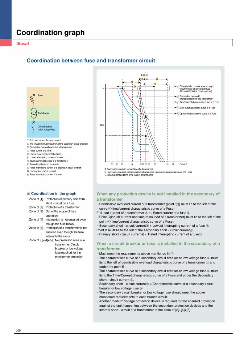
A. Permissible overload current/time of a transformer�B. Permissible overload characteristic of a transformer, Operation characteristic curve of a Fuse�C. inrush current and time at no load of a transformer
Full load current of a transformer �The lowest interrupting current of the secondary circuit breaker�Permissible overload current of a transformer�Rated current of a fuse�Lowest blow-out current of a fuse�Lowest interrupting current of a fuse�Inrush current at no load of a transformer�Secondary short-circuit current�Rated interrupting current of a secondary circuit breaker�Primary short-circuit current�Rated interrupting current of a fuse
Fuse
Transformer
Circuit breaker�or low voltage fuse
Characteristic curve of a secondary �circuit breaker or low voltage fuse �(Converted into the primary values)
Time
Permissible overload �characteristic curve of a transformerTime/Current characteristic curve of a Fuse
Blow-out characteristic curve of a Fuse
Operation characteristic curve of a Fuse
[1]
[2][3]
[4]
[5]
[6]
Current
Coordination between fuse and transformer circuit
When any protection device is not installed in the secondary of a transformer •�Permissible overload current of a transformer (point ③)) must lie to the left of the
curve ⓒ(time/current characteristic curve of a Fuse)Full load current of a transformer ① ≤ Rated current of a fuse ④•�Point C(inrush current and time at no load of a transformer) must lie to the left of the
point ⓒ(time/current characteristic curve of a Fuse)•Secondary short - circuit current⑧ > Lowest interrupting current of a fuse ⑥Point B must lie to the left of the secondary short - circuit current⑧.•Primary short - circuit current⑩ < Rated interrupting current of a fuse⑪
When a circuit breaker or fuse is installed in the secondary of a transformer•Must meet the requirements above mentioned in ①•�The characteristic curve of a secondary circuit breaker or low voltage fuse ⓐ must
lie to the left of permissible overload characteristic curve of a transformer ⓑ and under the point B•�The characteristic curve of a secondary circuit breaker or low voltage fuse ⓐ must
lie to the Time/Current characteristic curve of a Fuse and under the Secondary short - circuit current ⑧. •�Secondary short - circuit current⑧ < Characteristic curve of a secondary circuit
breaker or low voltage fuse ⓐ•�The secondary circuit breaker or low voltage fuse should meet the above
mentioned requirements to each branch circuit. •�Another medium voltage protection device is required for the ensured protection
against the fault happening between the secondary protection devices and the internal short - circuit of a transformer in the zone of [3]+[4]+[5].
※ Coordination in the graph•Zone of [1] : �Protection of primary side from
short - circuit by a fuse•Zone of [2] : �Protection of a transformer •Zone of [3] : �Out of the scope of fuse
operation •Zone of [4] : ��Interruption is not ensured even
though the fuse blows. •Zone of [5] : ��Protection of a transformer is not
ensured even though the fuse interrupts the circuit.
•Zone of [3]+[4]+[5] : ��No protection zone of a transformer Circuit breaker or low voltage fuse required for the transformer protection
��
A. Permissible overload current/time of a transformer�B. Permissible overload characteristic of a transformer, Operation characteristic curve of a Fuse�C. inrush current and time at no load of a transformer
Full load current of a transformer �The lowest interrupting current of the secondary circuit breaker�Permissible overload current of a transformer�Rated current of a fuse�Lowest blow-out current of a fuse�Lowest interrupting current of a fuse�Inrush current at no load of a transformer�Secondary short-circuit current�Rated interrupting current of a secondary circuit breaker�Primary short-circuit current�Rated interrupting current of a fuse
Fuse
Transformer
Circuit breaker�or low voltage fuse
Characteristic curve of a secondary �circuit breaker or low voltage fuse �(Converted into the primary values)
Time
Permissible overload �characteristic curve of a transformerTime/Current characteristic curve of a Fuse
Blow-out characteristic curve of a Fuse
Operation characteristic curve of a Fuse
[1]
[2][3]
[4]
[5]
[6]
Current
36
Coordination between fuse and motor circuit
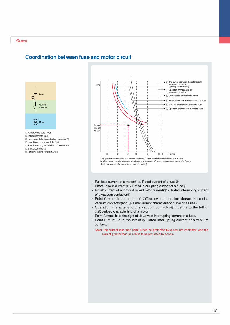
The lowest operation characteristic of �a vacuum contactor�(opening characteristic)Operation characteristic of�a vacuum contactorOverload characterictic of a motor
Time/Current characteristic curve of a Fuse
Blow-out characteristic curve of a Fuse
Operation characteristic curve of a Fuse
A : (Operation characteristic of a vacuum contactor, Time/Current characteristic curve of a Fuse)�B : (The lowest operation characteristic of a vacuum contactor, Operation characteristic curve of a Fuse )�C : ( Inrush current of a motor, Inrush time of a motor )
Inrush �time of �a motor Full load current of a motor�
Rated current of a fuse�Inrush current of a motor (Locked rotor current)�Lowest interrupting current of a fuse�Rated interrupting current of a vacuum contactor�Short-circuit current �Rated interrupting current of a fuse
Fuse
Vacuum �contactor
Motor
Time
Current
• �Full load current of a motor① ≤ Rated current of a fuse②• �Short - circuit current⑥ < Rated interrupting current of a fuse⑦• �Inrush current of a motor (Locked rotor current)③ < Rated interrupting current
of a vacuum contactor⑤• �Point C must lie to the left of ⓐ(The lowest operation characteristic of a
vacuum contactor)and ⓓ(Time/Current characteristic curve of a Fuse)• ��Operation characteristic of a vacuum contactorⓑ must lie to the left of ⓒ(Overload characteristic of a motor)
• �Point A must lie to the right of ④ Lowest interrupting current of a fuse.• �Point B must lie to the left of ⑤ Rated interrupting current of a vacuum
contactor.
Note) �The current less than point A can be protected by a vacuum contactor, and the current greater than point B is to be protected by a fuse.
The lowest operation characteristic of �a vacuum contactor�(opening characteristic)Operation characteristic of�a vacuum contactorOverload characterictic of a motor
Time/Current characteristic curve of a Fuse
Blow-out characteristic curve of a Fuse
Operation characteristic curve of a Fuse
A : (Operation characteristic of a vacuum contactor, Time/Current characteristic curve of a Fuse)�B : (The lowest operation characteristic of a vacuum contactor, Operation characteristic curve of a Fuse )�C : ( Inrush current of a motor, Inrush time of a motor )
Inrush �time of �a motor Full load current of a motor�
Rated current of a fuse�Inrush current of a motor (Locked rotor current)�Lowest interrupting current of a fuse�Rated interrupting current of a vacuum contactor�Short-circuit current �Rated interrupting current of a fuse
Fuse
Vacuum �contactor
Motor
Time
Current
37

Operation curves
DIN Type3.6/7.2kV blowing characteristic 3.6/7.2kV current limiting characteristic
3.6kV blowing characteristic 3.6kV current limiting characteristic
7.2kV blowing characteristic 7.2kV current limiting characteristic
Current ( sym, A )
Ope
ratio
n tim
e(se
c)
Current ( sym, A )
Ope
ratio
n tim
e(se
c)
Current ( sym, A )
Ope
ratio
n tim
e(se
c)
Interrupting current ( sym, kA )
Interrupting current ( sym, kA )
Cur
rent
lim
ited
( pea
k, k
A )
Cur
rent
lim
ited
( pea
k, k
A )
Interrupting current ( sym, kA )
Cur
rent
lim
ited
( pea
k, k
A )
38

KS TypeG(General use) type fuse
M(Motor protection) type fuse
3.6/7.2kV blowing characteristic 3.6/7.2kV current limiting characteristic
3.6kV blowing characteristic 7.2kV blowing characteristic
3.6kV, 7.2kV current limiting characteristic
Current ( sym, A )
Ope
ratio
n tim
e(se
c)
Current ( sym, A )
Ope
ratio
n tim
e(se
c)
Interrupting current ( sym, kA )
Interrupting current ( sym, kA )
Cur
rent
lim
ited
( pea
k, k
A )
Cur
rent
lim
ited
( pea
k, k
A )
Current ( sym, A )
Ope
ratio
n tim
e(se
c)
39

www.lsis.comⓒ 2014.11 LSIS Co., Ltd. All rights reserved.
Specifications in this catalog are subject to change without notice due to continuous product development and improvement.
▒ HEAD OFFICELS - ro 127 (Hogye - dong) Dongan - gu Anyang - si Gyeonggi - do Korea Tel. (82 - 2)2034 - 4840, 4911, 4914Fax. (82 - 2)2034 - 4648
▒ CHEONG - JU PLANTCheong - Ju Plant #1, 95 Baekbong - ro Heungdeok - gu Cheongju - si Chungcheongbuk - do 361 - 720 Korea
2014. 11 Susol LS Medium Voltage Vacuum Contactors (E) 2014. 11 / (1) 2014. 11 Printed in Korea STAFF
•LSIS USA Inc. ≫ Chicago, AmericaAddress : 2000 Millbrook Drive, Lincolnshire, Chicago, IL 60069, United States of AmericaTel : 847 - 941 - 8240 Fax : 847 - 941 - 8259 e - mail : [email protected]
•LSIS (Middle East) FZE ≫ Dubai, U.A.E.Address : LOB 19 JAFZA VIEW TOWER Room 205, Jebel Ali Freezone P.O. Box 114216, Dubai, United Arab EmiratesTel : 971 4 886 5360 Fax : 971 4 886 5361 e mail : hschoib@lsis com
•LSIS Europe B.V. ≫ Schiphol - Rijk, NetherlandsAddress : 1st. Floor, Tupolevlaan 48, 1119NZ, Schiphol - Rijk, The NetherlandsTel : 31 - 20 - 654 - 1420 Fax : 31 - 20 - 654 - 1429 e - mail : [email protected]
•LSIS - VINA Co., Ltd. ≫ Hanoi, VietnamAddress : Nguyen Khe - Dong Anh - Ha Noi - Viet NamTel : 84 - 4 - 882 - 0222 Fax : 84 - 4 - 882 - 0220 e - mail : [email protected]
•LSIS - VINA Co., Ltd. ≫ Hochiminh, VietnamAddress : 41 Nguyen Thi Minh Khai Str. Yoco Bldg 4th Floor, Hochiminh City, VietnamTel : 84 - 8 - 3822 - 7941 Fax : 84 - 8 - 3822 - 7942 e - mail : [email protected]
•LSIS Gurgaon Office ≫ Gurgaon, IndiaAddress : 109 First Floor, Park Central, Sector - 30, Gurgaon - 122 002, Haryana, IndiaTel : +0091 - 124 - 493 - 0070 Fax : 91 - 1244 - 930 - 066 e - mail : [email protected]
•LSIS Japan Co., Ltd. ≫ Tokyo, JapanAddress : Toykokurakubu Bldg. 13th floor, 3 - 2 - 6, Kasumigaseki, Chiyoda - ku, Tokyo, 100 - 0013 JapanTEL : +81 - 3 - 6268 - 8241 FAX : +81 - 3 - 6268 - 8240 e - mail : [email protected]
•LSIS Shanghai Office ≫ Shanghai, ChinaAddress : Room 32 floors of the Great Wall Building, No. 3000 North Zhongshan Road, Putuo District, Shanghai, ChinaTel : 86 - 21 - 5237 - 9977 Fax : 89 - 21 - 5237 - 7189 e - mail : [email protected]
•LSIS Beijing Office ≫ Beijing, ChinaAddress : B - Tower 17FL.Beijing Global Trade Center B / D. No.36, BeiSanHuanDong - Lu, DongCheng - District, Beijing 100013, P.R. ChinaTel : 86 - 10 - 5825 - 6025, 7 Fax : 86 - 10 - 5825 - 6026 e - mail : [email protected]
•LSIS Guangzhou Office ≫ Guangzhou, ChinaAddress : Room 1403, 14 / F, New Poly Tower, No.2 Zhongshan Liu Road, Guangzhou 510180, P.R. ChinaTel : 020 - 8326 - 6754 Fax : 020 - 8326 - 6287 e - mail : [email protected]
•LSIS Chengdu Office ≫ Chengdu, ChinaAddress : Room 1701 17Floor, huamin hanjun internationnal Building, No1 Fuxing Road Chengdu, 610016, P.R. ChinaTel : 86 - 28 - 8670 - 3201 Fax : 86 - 28 - 8670 - 3203 e - mail : [email protected]
•LSIS Qingdao Office ≫ Qingdao, ChinaAddress : Room 2001, 20 / F, 7B40, Galaxy Building, No.29 Shandong Road, Shinan District, Qingdao 266071, P.R. ChinaTel : 86 - 532 - 8501 - 6058 Fax : 86 - 532 - 8501 - 6057 e - mail : [email protected]
•LSIS (Wuxi) Co., Ltd. ≫ Wuxi, ChinaAddress : 102 - A, National High & New Tech Industrial Development Area, Wuxi, Jiangsu, 214028, P.R.ChinaTel : 86 - 510 - 8534 - 6666 Fax : 86 - 510 - 522 - 4078 e - mail : [email protected]
•Dalian LSIS Co., Ltd. ≫ Dalian, ChinaAddress : No.15, Liaohexi 3 - Road, Economic and Technical Development zone, Dalian 116600, ChinaTel : 86 - 411 - 8273 - 7777 Fax : 86 - 411 - 8730 - 7560 e - mail : [email protected]
▒ Global Network
•For your safety, please read user's manual thoroughly before operating.
•Contact the nearest authorized service facility for examination, repair, or adjustment.
•�Please contact qualified service technician when you need maintenance. Do not disassemble or repair by yourself!
•Any maintenance and inspection shall be performed by the personnel having expertise concerned.Safety Instructions
Top Related