


Languages
Pages
Legal

Manual Revision: 01/18/2016
For the latest information, technical specifications, and support for this product, please visit www.startech.com/ARMDUAL30.
FR: Guide de l’utilisateur - fr.startech.comDE: Bedienungsanleitung - de.startech.comES: Guía del usuario - es.startech.comNL: Gebruiksaanwijzing - nl.startech.comPT: Guia do usuário - pt.startech.comIT: Guida per l’uso - it.startech.com
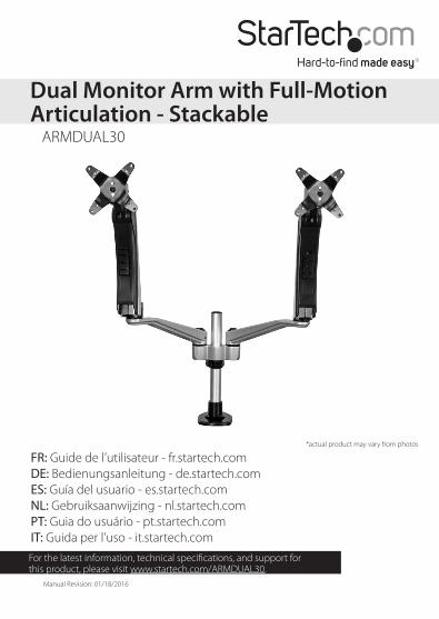
ARMDUAL30
Dual Monitor Arm with Full-Motion Articulation - Stackable
*actual product may vary from photos
Instruction manuali
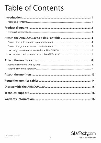
Table of ContentsIntroduction ............................................................................................1
Packaging contents .................................................................................................................................. 1
Product diagrams ...................................................................................2Technical specifications .......................................................................................................................... 3
Attach the ARMDUAL30 to a desk or table ........................................4Convert the desk mount to a grommet mount ............................................................................. 4
Convert the grommet mount to a desk mount ............................................................................. 5
Use the grommet mount to attach the ARMDUAL30 .................................................................. 6
Use the 2-in-1 desk mount to attach the ARMDUAL30 ............................................................... 7
Attach the monitor arms .......................................................................8Set up the monitors side-by-side ........................................................................................................ 8
Stack the monitors vertically ................................................................................................................ 9
Attach the monitors ...............................................................................13
Route the monitor cables .....................................................................14
Disassemble the ARMDUAL30 .............................................................15
Technical support ...................................................................................16
Warranty information ............................................................................16

Instruction manual1
IntroductionThe ARMDUAL30 is a full-articulation monitor mount that lets you mount and display your monitors in the setup that works best for you. The snap-and-release assembly makes the ARMDUAL30 easy to assemble and customize. Customizing options include assembling the mounting arms vertically or horizontally; using the dual mount attachment or attaching the mounting arms directly to the pole; changing the placement of the spring and swivel arms, and more.
Packaging contents
2-in-1 desk or grommet mount
Qty: OneM6 Allen key
Qty: Two
M3 Allen key
Qty: Two
Base cushion
Qty: One
Spring arm
Qty: Two
Swivel arm
Qty: Two
VESA monitor mount
Qty: TwoThumbscrews
Qty: Eight
Quick-release cable manager
Qty: TwoDual mount
Qty: One
Instruction manual
Qty: One
1. 2. 3. 4.
5. 6. 7. 8.
9. 10. 11.

Instruction manual2
Product diagrams
VESA monitor mount
VESA monitor mount
Spring arm Spring armSwivel arm Swivel arm
Dual mount
2-in-1 desk or grommet mount
(grommet pictured)
Cable manager
Instruction manual3
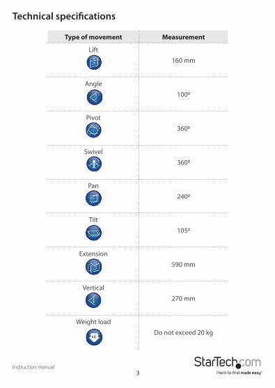
Technical specifications
Type of movement Measurement
Lift
160 mm
Angle
1000
Pivot
3600
Swivel
3600
Pan
2400
Tilt
1050
Extension
590 mm
Vertical
270 mm
Weight load
Do not exceed 20 kg

Instruction manual
There are four main tasks that you need to complete when you assemble the ARMDUAL30: Attach the ARMDUAL30 to a desk or table, attach the monitor arms, attach the monitors, and route the monitor cables.
Attach the ARMDUAL30 to a desk or tableBy default, the ARMDUAL30 comes with the desk mount preassembled.
Convert the desk mount to a grommet mount1. Turn the 2-in-1 desk mount (1) over so that the pole faces downwards. Use one of
the M3 Allen keys (3) to remove the four M5x14 mm hex screws that are holding the base of the pole to the desk clamp (figure 1).
M5x14 mm hex screw (x4)
M3 Allen key
2. Use a Phillips screwdriver (not included) to remove the M3 Phillips screw from the plate on the desk mount (figure 2).
3. Remove the plate, two washers, and the thumbscrew from the bottom of the desk mount (figure 2).
figure 2
M3 screw
Washers Plate
Thumbscrew
4. Use a Phillips screwdriver (not included) to remove the four M6x12 mm screws that are holding the two parts of the desk mount together (figure 3).
figure 3
M6x12 mm screws
figure 1
4
Instruction manual5
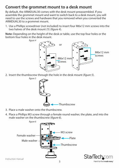
Convert the grommet mount to a desk mountBy default, the ARMDUAL30 comes with the desk mount preassembled. If you assemble the grommet mount and want to switch back to a desk mount, you will need to use the screws and hardware that you removed when you converted the ARMDUAL30 to a grommet mount.
1. Use a Phillips screwdriver (not included) to insert four M6x12 mm screws into the two halves of the desk mount (1) (figure 4).
Note: Depending on the height of the desk or table, use the top four holes or the bottom four holes in the desk mount.
figure 4
or
M6x12 mm screws
M6x12 mm screws
2. Insert the thumbscrew through the hole in the desk mount (figure 5).figure 5
Thumbscrew
3. Place a male washer onto the thumbscrew.
4. Place a Phillips M3 screw through a female round washer, the plate, and into the male washer on the thumbscrew (figure 6).
figure 6
M3 screwFemale washer
PlateMale washer
Thumbscrew
Instruction manual6
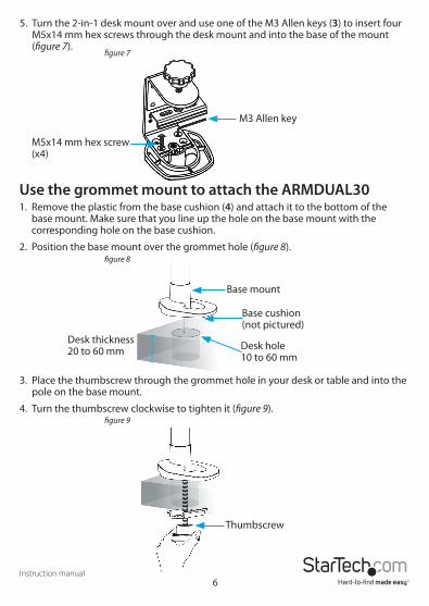
5. Turn the 2-in-1 desk mount over and use one of the M3 Allen keys (3) to insert four M5x14 mm hex screws through the desk mount and into the base of the mount (figure 7).
figure 7
M5x14 mm hex screw (x4)
M3 Allen key
Use the grommet mount to attach the ARMDUAL301. Remove the plastic from the base cushion (4) and attach it to the bottom of the
base mount. Make sure that you line up the hole on the base mount with the corresponding hole on the base cushion.
2. Position the base mount over the grommet hole (figure 8).
Base cushion (not pictured)
Base mount
Desk thickness 20 to 60 mm Desk hole
10 to 60 mm
3. Place the thumbscrew through the grommet hole in your desk or table and into the pole on the base mount.
4. Turn the thumbscrew clockwise to tighten it (figure 9).figure 9
Thumbscrew
figure 8
Instruction manual7
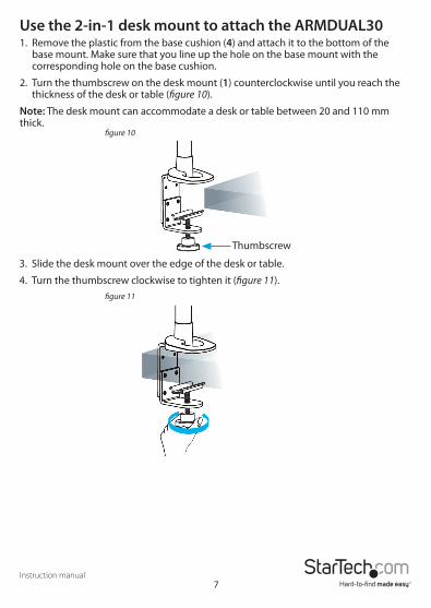
Use the 2-in-1 desk mount to attach the ARMDUAL301. Remove the plastic from the base cushion (4) and attach it to the bottom of the
base mount. Make sure that you line up the hole on the base mount with the corresponding hole on the base cushion.
2. Turn the thumbscrew on the desk mount (1) counterclockwise until you reach the thickness of the desk or table (figure 10).
Note: The desk mount can accommodate a desk or table between 20 and 110 mm thick.
figure 10
Thumbscrew
3. Slide the desk mount over the edge of the desk or table.
4. Turn the thumbscrew clockwise to tighten it (figure 11).figure 11
Instruction manual8
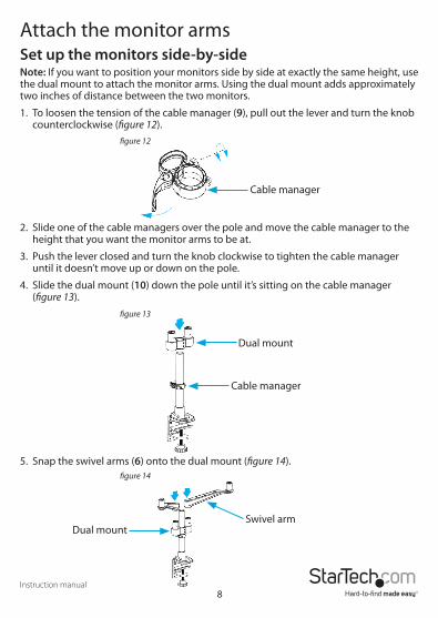
Attach the monitor armsSet up the monitors side-by-sideNote: If you want to position your monitors side by side at exactly the same height, use the dual mount to attach the monitor arms. Using the dual mount adds approximately two inches of distance between the two monitors.
1. To loosen the tension of the cable manager (9), pull out the lever and turn the knob counterclockwise (figure 12).
figure 12
figure 13
Cable manager
Cable manager
Dual mount
2. Slide one of the cable managers over the pole and move the cable manager to the height that you want the monitor arms to be at.
3. Push the lever closed and turn the knob clockwise to tighten the cable manager until it doesn’t move up or down on the pole.
4. Slide the dual mount (10) down the pole until it’s sitting on the cable manager (figure 13).
5. Snap the swivel arms (6) onto the dual mount (figure 14).figure 14
Dual mountSwivel arm
Instruction manual9
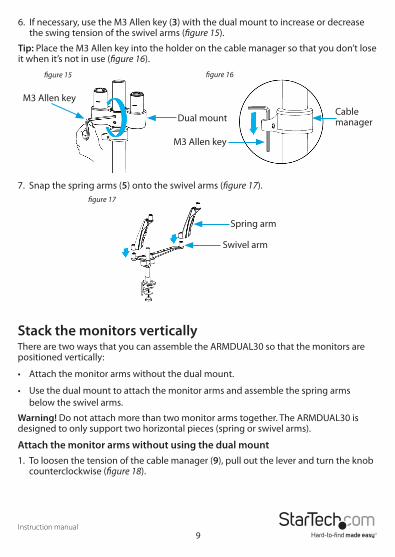
6. If necessary, use the M3 Allen key (3) with the dual mount to increase or decrease the swing tension of the swivel arms (figure 15).
Tip: Place the M3 Allen key into the holder on the cable manager so that you don’t lose it when it’s not in use (figure 16).
figure 17
figure 16figure 15
M3 Allen keyCable managerDual mount
M3 Allen key
Swivel arm
Spring arm
7. Snap the spring arms (5) onto the swivel arms (figure 17).
Stack the monitors verticallyThere are two ways that you can assemble the ARMDUAL30 so that the monitors are positioned vertically:
• Attach the monitor arms without the dual mount.
• Use the dual mount to attach the monitor arms and assemble the spring arms below the swivel arms.
Warning! Do not attach more than two monitor arms together. The ARMDUAL30 is designed to only support two horizontal pieces (spring or swivel arms).
Attach the monitor arms without using the dual mount1. To loosen the tension of the cable manager (9), pull out the lever and turn the knob
counterclockwise (figure 18).

Instruction manual10
figure 18
Cable manager
2. Slide one of the cable managers over the pole and move the cable manager to the height that you want the monitor arms to be at.
3. Slide one of the swivel arms (6) down the pole until it’s sitting on the cable manager (figure 19).
figure 20
Swivel arm
Spring arm
figure 19Swivel arm
Cable manager
4. Slide the second cable manager down the pole so that it’s sitting on the first swivel arm.
5. Slide the second swivel arm down the pole so that it’s sitting on the second cable manager.
6. Snap the spring arms (5) onto the swivel arms (figure 20).
7. If necessary, use the M3 Allen key (3) to increase or decrease the swing tension of the arms (figure 21).
Tip: Place the M3 Allen key into the holder on the cable manager so that you don’t lose it when it’s not in use (figure 22).

Instruction manual11
figure 21 figure 22
M3 Allen key
M3 Allen key
Cable manager
Use the dual mount to attach the monitor armsYou can customize the ARMDUAL30 by changing the order in which you assemble the monitor arms or by using just the swivel arms or the spring arms. You can also assemble one set of monitor arms in one configuration and assemble the other set in a different configuration.
1. To loosen the tension of the cable manager (9), pull out the lever and turn the knob counterclockwise (figure 23).
figure 23
Cable manager
2. Slide one of the cable managers over the pole and move the cable manager to the height that you want the monitor arms to be at.
3. Push the lever closed and turn the knob clockwise to tighten the cable manager until it doesn’t move up or down on the pole.
4. Slide the dual mount (10) down the pole until it’s sitting on the cable manager (figure 24).
figure 24
Dual mount
Cable manager
Instruction manual12
figure 25
Spring arm
Dual mount
figure 26 figure 27
M3 Allen keyDual mount
M3 Allen key
Cable manager
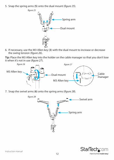
5. Snap the spring arms (5) onto the dual mount (figure 25).
6. If necessary, use the M3 Allen key (3) with the dual mount to increase or decrease the swing tension (figure 26).
Tip: Place the M3 Allen key into the holder on the cable manager so that you don’t lose it when it’s not in use (figure 27).
7. Snap the swivel arms (6) onto the spring arms (figure 28).
12
Spring arm
Swivel armfigure 28
Instruction manual13
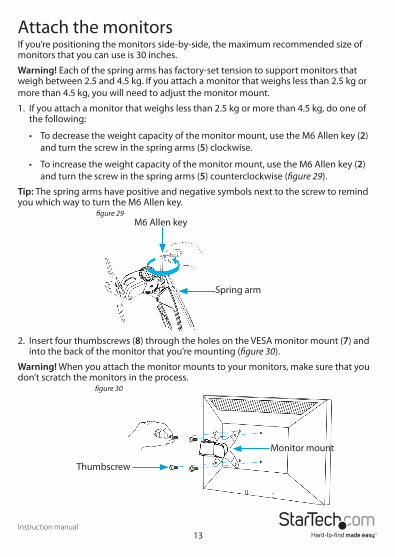
Attach the monitorsIf you’re positioning the monitors side-by-side, the maximum recommended size of monitors that you can use is 30 inches.
Warning! Each of the spring arms has factory-set tension to support monitors that weigh between 2.5 and 4.5 kg. If you attach a monitor that weighs less than 2.5 kg or more than 4.5 kg, you will need to adjust the monitor mount.
1. If you attach a monitor that weighs less than 2.5 kg or more than 4.5 kg, do one of the following:
• To decrease the weight capacity of the monitor mount, use the M6 Allen key (2) and turn the screw in the spring arms (5) clockwise.
• To increase the weight capacity of the monitor mount, use the M6 Allen key (2) and turn the screw in the spring arms (5) counterclockwise (figure 29).
Tip: The spring arms have positive and negative symbols next to the screw to remind you which way to turn the M6 Allen key.
figure 29M6 Allen key
Spring arm
2. Insert four thumbscrews (8) through the holes on the VESA monitor mount (7) and into the back of the monitor that you’re mounting (figure 30).
Warning! When you attach the monitor mounts to your monitors, make sure that you don’t scratch the monitors in the process.
figure 30
Thumbscrew
Monitor mount
Instruction manual14
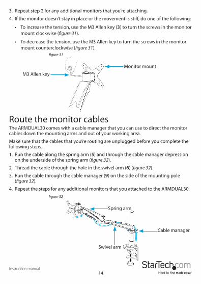
3. Repeat step 2 for any additional monitors that you’re attaching.
4. If the monitor doesn’t stay in place or the movement is stiff, do one of the following:
• To increase the tension, use the M3 Allen key (3) to turn the screws in the monitor mount clockwise (figure 31).
• To decrease the tension, use the M3 Allen key to turn the screws in the monitor mount counterclockwise (figure 31).
figure 31
Monitor mount
M3 Allen key
Route the monitor cablesThe ARMDUAL30 comes with a cable manager that you can use to direct the monitor cables down the mounting arms and out of your working area.
Make sure that the cables that you’re routing are unplugged before you complete the following steps.
1. Run the cable along the spring arm (5) and through the cable manager depression on the underside of the spring arm (figure 32).
2. Thread the cable through the hole in the swivel arm (6) (figure 32).
3. Run the cable through the cable manager (9) on the side of the mounting pole (figure 32).
4. Repeat the steps for any additional monitors that you attached to the ARMDUAL30.figure 32
Cable manager
Swivel arm
Spring arm

Instruction manual15
Disassemble the ARMDUAL301. Remove the thumbscrews (8) from the back of the monitors and the monitor
mounts (7).
Warning! Make sure that you lift the mounting arm up to its highest position when you remove the monitor. When you remove the weight of the monitor, the arm could bounce upward and cause injury.
2. To remove the monitor mounts and mounting arms, slide the textured button away from you on each of the mounts and arms and lift them up (figure 33).
3. Pull the mounting arm and the dual mount (if used) free from the pole.
4. To loosen the tension of the cable manager (9), pull out the lever and turn the knob counterclockwise, and remove the cable manager from the pole.
5. Remove the base of the ARMDUAL30 from the table or desk that it was attached to.
figure 33
Cable manager
Swivel armSpring arm
Monitor mount

Instruction manual16
Technical supportStarTech.com’s lifetime technical support is an integral part of our commitment to provide industry-leading solutions. If you ever need help with your product, visit www.startech.com/support and access our comprehensive selection of online tools, documentation, and downloads.For the latest drivers/software, please visit www.startech.com/downloads
Warranty informationThis product is backed by a two-year warranty. StarTech.com warrants its products against defects in materials and workmanship for the periods noted, following the initial date of purchase. During this period, the products may be returned for repair, or replacement with equivalent products at our discretion. The warranty covers parts and labor costs only. StarTech.com does not warrant its products from defects or damages arising from misuse, abuse, alteration, or normal wear and tear.
Limitation of LiabilityIn no event shall the liability of StarTech.com Ltd. and StarTech.com USA LLP (or their officers, directors, employees or agents) for any damages (whether direct or indirect, special, punitive, incidental, consequential, or otherwise), loss of profits, loss of business, or any pecuniary loss, arising out of or related to the use of the product exceed the actual price paid for the product. Some states do not allow the exclusion or limitation of incidental or consequential damages. If such laws apply, the limitations or exclusions contained in this statement may not apply to you.
Use of Trademarks, Registered Trademarks, and other Protected Names and SymbolsThis manual may make reference to trademarks, registered trademarks, and other protected names and/or symbols of third-party companies not related in any way to StarTech.com. Where they occur these references are for illustrative purposes only and do not represent an endorsement of a product or service by StarTech.com, or an endorsement of the product(s) to which this manual applies by the third-party company in question. Regardless of any direct acknowledgement elsewhere in the body of this document, StarTech.com hereby acknowledges that all trademarks, registered trademarks, service marks, and other protected names and/or symbols contained in this manual and related documents are the property of their respective holders.

Hard-to-find made easy. At StarTech.com, that isn’t a slogan. It’s a promise.
StarTech.com is your one-stop source for every connectivity part you need. From the latest technology to legacy products — and all the parts that bridge the old and new — we can help you find the parts that connect your solutions.
We make it easy to locate the parts, and we quickly deliver them wherever they need to go. Just talk to one of our tech advisors or visit our website. You’ll be connected to the products you need in no time.
Visit www.startech.com for complete information on all StarTech.com products and to access exclusive resources and time-saving tools.
StarTech.com is an ISO 9001 Registered manufacturer of connectivity and technology parts. StarTech.com was founded in 1985 and has operations in the United States, Canada, the United Kingdom and Taiwan servicing a worldwide market.
Top Related