


Languages
Pages
Legal


Automatic Structural Synthesis of Planar Mechanisms and Its Application to Creative
Design
Von der Fakultät für Ingenieurwissenschaften
Abteilung Maschinenbau und Verfahrenstechnik der Universität Duisburg-Essen
zur Erlangung des akademischen Grades
eines
Doktors der Ingenieurwissenschaften
Dr.-Ing.
genehmigte Dissertation
von
Huafeng Ding
aus
Hebei Gutachter: Prof. Dr.-Ing. Andrés Kecskeméthy
Prof. Dr.-Ing. Burkhard Corves, RWTH Aachen
Tag der mündlichen Prüfung: 18.02.2015

Automatic Structural Synthesis of Planar
Mechanisms and Its Application to Creative Design
Doctor thesis
Written by
Huafeng Ding
Supervised by
Prof. Dr. Andrés Kecskeméthy
Fakultät für Ingenieurwissenschaften
Abteilung Maschinenbau
Institut für Mechanik und Robotik
Contents
1 Introduction ........................................................................................................................ 1
1.1 Purpose of the thesis .............................................................................................. 1
1.2 Review of structural synthesis ............................................................................... 2
1.2.1 Franke’s notation methods .................................................................................... 2
1.2.2 Graph theory based methods ................................................................................. 2
1.2.3 Assur group based methods ................................................................................... 3
1.2.4 Group theory based methods ................................................................................. 3
1.2.5 Transformation methods ....................................................................................... 3
1.2.6 Additive methods .................................................................................................. 4
1.2.7 Other methods ....................................................................................................... 4
1.3 Open problems in structural synthesis .................................................................. 4
1.3.1 No complete automation ....................................................................................... 5
1.3.2 No classified atlas database ................................................................................... 5
1.3.3 No unified synthesis method ................................................................................. 6
1.4 Contents of the thesis ............................................................................................ 6
2 Graph based models of planar mechanisms ....................................................................... 9
2.1 Foreword ............................................................................................................... 9
2.2 Modeling of simple joint kinematic chains ........................................................... 9
2.3 Non-fractionated and fractionated kinematic chains ........................................... 11
2.4 Modeling of multiple joint kinematic chains ...................................................... 12
2.5 Modeling of geared kinematic chains ................................................................. 14
2.6 Summary ............................................................................................................. 17
3 Structural synthesis of non-fractionated contracted graphs ............................................. 19
3.1 Foreword ............................................................................................................. 19
3.2 4-parameter index of a kinematic family ............................................................ 19
3.3 Link assortment array .......................................................................................... 19
3.4 Relationship of link assortment arrays ................................................................ 20
3.5 Synthesis equation set of contracted graphs ........................................................ 23
3.6 Generation of contracted graph matrices............................................................. 24
3.7 Identification of fractionated structures .............................................................. 27
3.8 Unique representation of contracted graphs ........................................................ 27
3.9 Synthesis results .................................................................................................. 30
3.10 Summary ............................................................................................................. 35
4 Structural synthesis of non-fractionated kinematic chains and mechanisms ................... 37
4.1 Foreword ............................................................................................................. 37
4.2 Synthesis requirements ........................................................................................ 37
4.3 Synthesis progress ............................................................................................... 37
4.4 Synthesis equation set ......................................................................................... 39
4.5 Unique representation of graphs ......................................................................... 44
4.6 Detection of rigid sub-chains .............................................................................. 45
4.7 Atlas database of kinematic chains and mechanisms .......................................... 47
4.8 Summary ............................................................................................................. 58
5 Structural synthesis of fractionated kinematic chains ...................................................... 59
5.1 Foreword ............................................................................................................. 59
5.2 Synthesis modeling ............................................................................................. 59
5.3 Synthesis of 2-DOF fractionated kinematic chains ............................................. 61
5.3.1 Rules of combination .......................................................................................... 61
5.3.2 Combination of “AA” type ................................................................................. 63
5.3.3 Combination of “AB” type .................................................................................. 65
5.3.4 Synthesis results of 2-DOF fractionated kinematic chains ................................. 67
5.4 Combination of three non-fractionated kinematic chains ................................... 68
5.4.1 Combination rules for three identical kinematic chains ...................................... 69
5.4.2 Combination rules for two identical and a different one ..................................... 72
5.4.3 Combination rules for three different kinematic chains ...................................... 76
5.5 Synthesis of 3- DOF fractionated kinematic chains ............................................ 77
5.5.1 Synthesis of “L” type .......................................................................................... 77
5.5.2 Synthesis of “J” type ........................................................................................... 78
5.5.3 Synthesis of “2L” type ........................................................................................ 79
5.5.4 Synthesis results of 3-DOF fractionated kinematic chains ................................. 80

5.6 Synthesis of 4- DOF fractionated kinematic chains ............................................ 82
5.6.1 Synthesis of “L” type ........................................................................................... 82
5.6.2 Synthesis of “2L” type ......................................................................................... 83
5.6.3 Synthesis of “3L” type ......................................................................................... 84
5.6.4 Synthesis of “J” type ........................................................................................... 86
5.6.5 Synthesis of “L-J” type ....................................................................................... 86
5.6.6 Synthesis of “J-V” type ....................................................................................... 88
5.6.7 Synthesis results of 4-DOF fractionated kinematic chains ................................. 89
5.7 Summary ............................................................................................................. 93
6 Structural synthesis of multiple joint kinematic chains ................................................... 95
6.1 Foreword ............................................................................................................. 95
6.2 Relationship of simple and multiple joint kinematic chains ............................... 95
6.3 Synthesis method ................................................................................................. 97
6.4 Unique representation and isomorphism identification .................................... 100
6.5 Synthesis process ............................................................................................... 103
6.6 Automatic synthesis and classified atlas databases ........................................... 108
6.7 Summary ........................................................................................................... 116
7 Conceptual creative design of mechanisms ................................................................... 117
7.1 Foreword ........................................................................................................... 117
7.2 Design procedure ............................................................................................... 117
7.3 Creative design of 2-DOF mechanisms for road tractors .................................. 119
7.4 Creative design of 3-DOF hydraulic driven robots ........................................... 125
7.5 Creative design of forging manipulators ........................................................... 128
7.6 Summary ........................................................................................................... 133
8 Conclusions .................................................................................................................... 135
References .............................................................................................................................. 137
List of publication during the doctoral study ......................................................................... 145
Acknowledgements ................................................................................................................ 147

1
1 Introduction
1.1 Purpose of the thesis
In the design of various mechanism-based products or systems, conceiving the kinematic
structure of mechanisms with better performance has been a challenging yet pivotal issue for
every specified design task [1-7]. For a long time, it has been researchers’ experience and
intuition that are mostly relied on in the conception of candidate structures and the selection
of one of them for the task. Obviously, some of the feasible mechanisms satisfying the
requirements of a specified design task can be conceived based on the researchers’ experience
with creative design methods [8-12]. But it is hard or impossible to conceive all the possible
kinematic structures of mechanisms for each design task in this way and the best solution for
a task can hardly be reached. The mechanism with the best performance for a specified design
task can be selected only when all the feasible kinematic structures of mechanisms are
obtained. For example, Figure 1(a) shows a road tractor [13]. The mechanism for the tractor
has 11 links and two DOFs and its kinematic sketch is shown in Fig. 1(b). Now two important
questions to ask are
(1) Is the mechanism in Fig. 1(b) the best for an 11-link 2-DOF road tractor?
(2) what are the alternatives for it?
74
7
7
10
9
811
2
3
1
6
5
A0
A
B0
C0
N C
HKL
D
F
(a) (b)
Fig. 1 (a) A road tractor, (b) the kinematic sketch of the mechanism
Obviously, only when all feasible mechanisms that satisfy the design requirements are
synthesized and evaluated against detailed design constraints it may be possible to obtain the
best mechanism for the task. The structural synthesis of mechanisms which can generate a
complete list of kinematic chains and mechanisms free from isomorphism and degenerate
chains can provide the designers with all the independent candidate kinematic structures of
mechanisms of choice [15-17]. From the reports in literature, the number of the topological
structures of mechanisms is far more than the species of creatures in the nature [18-19]. Thus,
in order to get the optimal result from structural synthesis, the synthesis method must have the
following characteristics [20-22]:
(1) Effectiveness: The method must be abe to generate all valid topological structures, free
from any degenerate structures (rigid sub-chains) and redundant structures (isomorphic

2
chains), and at once without omission of any independent structures (the charater of
completeness).
(2) Automation: Synthesis must be carried out completely automatically in the computer.
(3) Designer-friendliness: Synthesis results should be displayed in intuitive forms instead of
as algebraic representations so that designers can have a quick understanding of them.
Despite a great number of existing synthesis methods, no method so far meets the three
requirements above [17]. This thesis attempts to develop a novel synthesis method which is at
the same time effective, automatic and designer-friendly, and with which one can obtain at the
one side all the valid topological structures of planar kinematic chains and mechanisms with
simple or multiple joints, and on the other side develop the atlas database containing all the
topological graphs for these kinematic chains and mechanisms with different numbers of links,
classified by their structural characteristics. Based on the classified atlas database, a creative
design method is also proposed to generate all the feasible mechanisms from the topological
graphs for a specified task within specified design constraints.
1.2 Review of structural synthesis
Structure synthesis of planar mechanisms has attracted researchers for over a century and
continues to do so. At its early time structure synthesis was mainly based on researchers’
experience and intuition. Since the 1960s, many systematic approaches have been proposed
for the synthesis of mechanism kinematic chains. The main synthesis methods reported in
literature can be sorted into link-joint based methods, limb based methods, loop based
methods, and some others.
1.2.1 Franke’s notation methods
Davies and Crossley [23] proposed the structural synthesis method based on Franke’s
notation [24], with which 40 9-link 2-DOF kinematic chains and 230 10-link 3-DOF
kinematic chains were synthesized in batch. Hass and Crossley [25] used Franke’s notation to
synthesize a class of four degrees of freedom kinematic chains. Soni [26] also employed
Franke’s notation to synthesize two general constraint kinematic chains.
1.2.2 Graph theory based methods
Freudenstein [27] and Crossley [28] employed the graphs in graph theory [29] to represent
the topological structures of kinematic chains and developed a method to synthesize 16 8-link
1-DOF kinematic chains by hand. Woo [30] proposed an algebraic interchange method to
synthesize contracted graphs and then add binary-link vertices to these contracted graphs to
synthesize topological graphs. With this method he synthesized 230 10-link 1-DOF kinematic
chains. Freudenstein and Woo [31-33] introduced Polya’s theory to synthesize topological
graphs by adding binary-link vertices to contracted graphs. Huang and Soni [34] further
employed Polya’s theory to synthesize 8-link 1-DOF kinematic chains with other types of
joints. Kiper and Schian [35-36] employed the graph theory to synthesize 6856 12-link 1-
DOF kinematic chains. Liu [37] presented a graph theory based approach to optimize type

3
synthesis of vehicle suspension mechanisms. Pucheta [38-39] used the graph representation to
solve the number synthesis of a class of planar multiloop linkages. By adopting a Mckay-type
algorithm [40], Sunkari and Schmidt [41] synthesized the graphs of planar kinematic chains
using graph and group theoretic techniques. Lu [42-45] conducted the structural synthesis of
some topological graphs of planar parallel mechanisms based on topology embryonic graphs
and arrays. Based on the concept of the simplified unified graph, Yan [46] proposed a method
for the configuration synthesis of mechanism with variable topologies. By constructing proper
simplified graphs, Butcher and Hartman [47] listed the numbers of 12- and 14-bar planar
single degree-of-freedom kinematic chains.
1.2.3 Assur group based methods
Assur [48] proposed the famous concept of Assur group to reveal the structure composition
of planar mechanisms. The basis for the concept lies in the fact that additon of an Assur group
to a link or links of an existing kinematic chain does not change the degrees of freedom of the
chain. So kinematic chains of greater complexity (i.e. with greater number of links) could be
built by the sequential addition of these Assur groups to simpler kinematic chains (i.e. with
fewer number of links). Using the concept of Assur group, Manolescu [49-54] studied the
structural synthesis of 1-DOF kinematic chains up to 10 links and 2-DOF kinematic chains up
to 9 links. Chu and Cao [55-57] proposed a method for the synthesis of Assur groups with
multiple joints by synthesizing the internal chains and external chains in turn. Tischler [58-59]
developed a method to synthesize multi-tipped fingers of a robot hand on the basis of Assur
groups. Based on Assur groups as the simplest basic blocks to build kinematic chains,
Alexandre [60] proposed a method to synthesize hybrid robots as a whole structure. By
integrating Assur groups as elements in the modified adjacency matrix, Li [61] proposed a
method to synthesize planar mechanisms with both R and P joints.
1.2.4 Group theory based methods
Tuttle [62-65] proposed a method wherein the feasible patterns called the bases of
connecting polygonal links are formed first and the desired kinematic chains are derived by
distributing binary links among these bases. The theory of finite symmetry groups is used to
eliminate isomorphic entities in the generation of bases as well as kinematic chains. Based on
the theory of permutation groups, Yan and coworkers [66-68] proposed the method to
synthesize kinematic chains and mechanisms. Based on modified permutation groups and
Polya's theory, Yan and Hung [69-71] presented a systematic procedure to count the number
of planar mechanisms subject to design constraints from the candidate kinematic chains.
Hervé, Li and Lee [72-75] developed the group-based synthesis method to synthesize lower-
mobility parallel mechanisms by using displacement subgroups to represent the motion of the
moving platform and limb chains.
1.2.5 Transformation methods
By extending Manolescu’s work [76], Mruthyunjaya [77-82] proposed a method based on
the transformation of binary chains to synthesize kinematic chains with positive, zero and

4
negative DOFs. The complete collection of 839 11-link 2-DOF kinematic chains was
synthesized. Sohn and Freudenstein [83] represented a conventional graph with its dual graph
in which the vertices represent the loops and the loops represent the vertices of the
conventional graph and developed the dual graph based method to synthesize planar
kinematic chains whose graphs are planar.
1.2.6 Additive methods
Yang [84-86] developed a method for structural synthesis of kinematic chains with planar
and non-planar graphs on the basis of the single-opened chain technique. Rao [87-88] applied
the Hamming number technique to the structural synthesis of kinematic chains by using F-
DOF, (N-2)-link chains as the basic chains for the synthesis of F-DOF, N-link chains.
Varadaraju [89] proposed a method to build simple joint kinematic chains by adding one link
at a time in all possible ways to an existing structural pattern. Vijayananda [90] developed a
synthesis method in which a desired chain is built by adding specially constructed assemblage
of links called “link patterns” to a chain with fewer numbers of links called “parent kinematic
chain”.
1.2.7 Other methods
Hwang and Hwang [91] proposed a new matrix, the contracted link adjacency matrix, to
represent kinematic chains, and used it as the representation matrix to synthesize kinematic
chains. Yan and Hsu [92-94] proposed the graph representation of multiple joint kinematic
chains using solid polygons to represent multiple joints, and based on the concept of
contracted graphs developed a method for the structure synthesis of kinematic chains with
simple and multiple joints. Also using solid polygons to represent multiple joints, Hsu and
Hsu [95] proposed a systematic method to synthesize geared kinematic chains using acyclic
graphs. Rao and Deshmukh [96] used the loop information of kinematic chains to synthesize
planar kinematic chains obviating the test for isomorphism, and kinematic chains up to 230
10-link 1-DOF kinematic chains were synthesized successfully. Lan and Du [97] proposed a
new adjacency matrix to represent the topological changes of metamorphic mechanisms [98].
Song [99-101] presented a combination method to synthesize planar multiple joint kinematic
chain under 10-link. Li [102] used the linear equations to synthesize planar single-freedom,
simple-joint kinematic chains with up to 12 links. Mitrouchev [103] proposed the notion of
logical equations to synthesize planar kinematic chains.
1.3 Open problems in structural synthesis
Although structural synthesis methods proposed one after another resulted in successful
synthesis of an enormous number of kinematic chains and mechanisms of various links and
degrees of freedom, a general problem still unsolved in structural synthesis is the enumeration
of a complete list of kinematic chains and mechanisms without isomorphism and without
degenerate (or rigid-sub) chains [15,17].
5
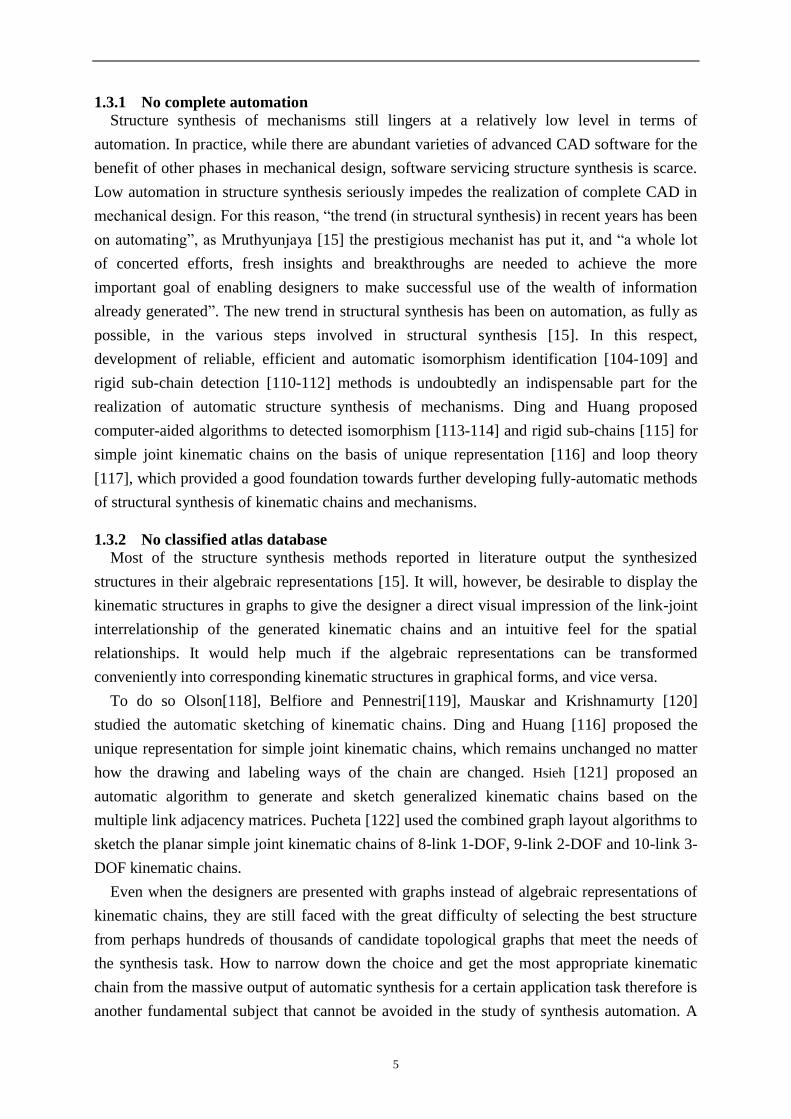
1.3.1 No complete automation
Structure synthesis of mechanisms still lingers at a relatively low level in terms of
automation. In practice, while there are abundant varieties of advanced CAD software for the
benefit of other phases in mechanical design, software servicing structure synthesis is scarce.
Low automation in structure synthesis seriously impedes the realization of complete CAD in
mechanical design. For this reason, “the trend (in structural synthesis) in recent years has been
on automating”, as Mruthyunjaya [15] the prestigious mechanist has put it, and “a whole lot
of concerted efforts, fresh insights and breakthroughs are needed to achieve the more
important goal of enabling designers to make successful use of the wealth of information
already generated”. The new trend in structural synthesis has been on automation, as fully as
possible, in the various steps involved in structural synthesis [15]. In this respect,
development of reliable, efficient and automatic isomorphism identification [104-109] and
rigid sub-chain detection [110-112] methods is undoubtedly an indispensable part for the
realization of automatic structure synthesis of mechanisms. Ding and Huang proposed
computer-aided algorithms to detected isomorphism [113-114] and rigid sub-chains [115] for
simple joint kinematic chains on the basis of unique representation [116] and loop theory
[117], which provided a good foundation towards further developing fully-automatic methods
of structural synthesis of kinematic chains and mechanisms.
1.3.2 No classified atlas database
Most of the structure synthesis methods reported in literature output the synthesized
structures in their algebraic representations [15]. It will, however, be desirable to display the
kinematic structures in graphs to give the designer a direct visual impression of the link-joint
interrelationship of the generated kinematic chains and an intuitive feel for the spatial
relationships. It would help much if the algebraic representations can be transformed
conveniently into corresponding kinematic structures in graphical forms, and vice versa.
To do so Olson[118], Belfiore and Pennestri[119], Mauskar and Krishnamurty [120]
studied the automatic sketching of kinematic chains. Ding and Huang [116] proposed the
unique representation for simple joint kinematic chains, which remains unchanged no matter
how the drawing and labeling ways of the chain are changed. Hsieh [121] proposed an
automatic algorithm to generate and sketch generalized kinematic chains based on the
multiple link adjacency matrices. Pucheta [122] used the combined graph layout algorithms to
sketch the planar simple joint kinematic chains of 8-link 1-DOF, 9-link 2-DOF and 10-link 3-
DOF kinematic chains.
Even when the designers are presented with graphs instead of algebraic representations of
kinematic chains, they are still faced with the great difficulty of selecting the best structure
from perhaps hundreds of thousands of candidate topological graphs that meet the needs of
the synthesis task. How to narrow down the choice and get the most appropriate kinematic
chain from the massive output of automatic synthesis for a certain application task therefore is
another fundamental subject that cannot be avoided in the study of synthesis automation. A

6
system that contains all the topological characteristics of the topological graphs produced
from automatic synthesis and can classify, store and output these graphs by their topological
characteristics might be a good solution to the problem.
1.3.3 No unified synthesis method
Besides simple joint kinematic chains, typical planar kinematic chains also include multiple
joint chains, gear chains, etc. If we develop an individual synthesis theory for each kind of
planar kinematic chains respectively, the overall issue of structure synthesis of planar
mechanisms would become complex and confusing. Moreover, very likely a synthesis theory
developed for a certain kind of mechanism in its isolated form cannot be applied to combined
mechanisms directly and easily. So it would be more desirable both theoretically and
practically to come up with a unified structure representation model and a unified structure
synthesis theory applicable to all kinds of planar mechanisms. At present, researches on
structure synthesis of simple joint chains are the most fruitful, but structure synthesis theories
of other types of mechanisms are far from being fully developed. So it would save researchers
much trouble if the unified model and the unified theory are closely related to those of simple
joint kinematic chains, and the accomplishments on simple joint chains can service future
researches into other types of planar mechanisms.
1.4 Contents of the thesis
Based on the discussed background this thesis aims to study a unified structure synthesis
method of planar kinematic chains and mechanisms with simple and multiple joints
characterized by effectiveness, automation and human-machine interaction, and to develop the
atlas database containing all the topological graphs for these kinematic chains and
mechanisms with different numbers of links, classified by their structural characteristics.
Based on the classified atlas database, the creative design of several kinds of mechanisms is
also conducted to verify the usefulness of the method. The overall structure of the thesis is as
follows.
In chapter 2, the representation models of planar kinematic chains with simple joints,
multiple joints and geared joints are proposed and the relationships between these models are
also revealed.
In chapter 3, the relationships between the contracted graphs of planar non-fractionated
kinematic chains are revealed first. Then a fully-automatic method is proposed to synthesize
the whole family of contracted graphs for planar non-fractionated kinematic chains with all
possible degrees of freedom.
In chapter 4, a general method is proposed to synthesize planar non-fractionated kinematic
chains and mechanisms based on the contracted graphs obtained in chapter 3. The method is
fully-automatic and designer-friendly, and planar non-fractionated kinematic chains and
mechanisms with up to 19 links are synthesized. Moreover, the classified atlas databases for
these kinematic chains and mechanisms are also established.

7
In chapter 5, based on the structure characteristics of fractionated kinematic chains, a
general synthesis equation of planar fractionated kinematic chains is proposed first. Then an
automatic method is proposed to synthesize planar fractionated kinematic chains by the
combination of planar non-fractionated kinematic chains, and the whole family of planar
fractionated kinematic chains up to seven basic loops is synthesized with the method.
In chapter 6, based on the new bicolor topological graph and its inter-convertible
characteristics with that of simple joint kinematic chains, an automatic method is proposed to
synthesize multiple joint kinematic chains from simple joint kinematic chains and their
classified atlas databases. The whole family of multiple joint kinematic chains with up to 16
links is synthesized with the method and corresponding classified atlas databases are also
established.
In chapter 7, based on the structural synthesis and classified atlas databases of kinematic
chains with simple and multiple joints, a creative design method is proposed to obtain all the
feasible mechanisms for a specified task from the topological graphs in the classified atlas
databases subject to design constraints. Examples of the creative design of road tractors,
hydraulic driven robots and forging manipulators are also conducted.

8
9
2 Graph based models of planar mechanisms
2.1 Foreword
The kinematic structure of a mechanism contains the essential information about which link is
connected to which other link by what type of joint. In IFToMM, many different ways have
been adopted to represent the kinematic structures of mechanisms, such as the functional
schematic representation, structural representation, and so on. Graph theory, which is
mathematically rigorous, visually intuitive, and easily adaptable to computation, is a powerful
mathematical tool for the structural analysis and synthesis of various planar mechanisms. In
the chapter, the graph based models of planar mechanisms or kinematic chains with simple
joints, multiple joints and geared joints are presented.
2.2 Modeling of simple joint kinematic chains
In the process of structural synthesis and creative design of mechanisms, a mechanism is
usually represented by its kinematic chain. The frame of the mechanism is represented by an
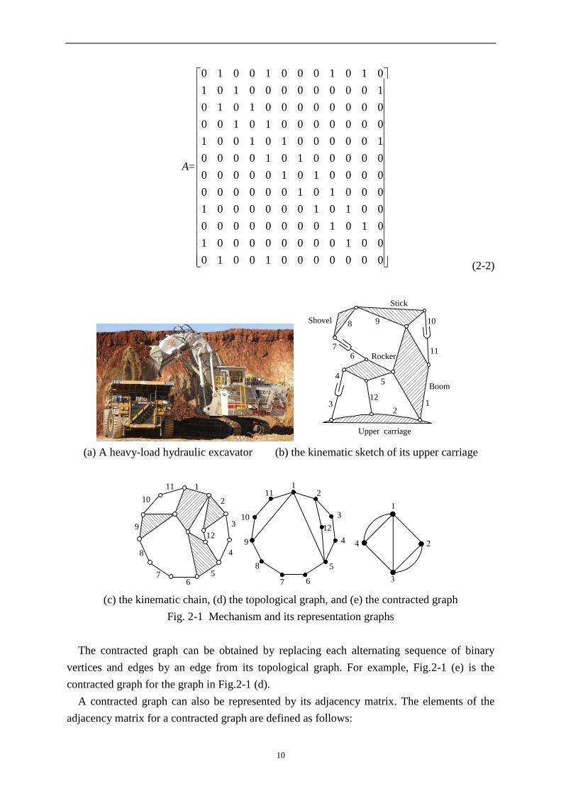
appropriate link, and all joints are assumed to be revolute. Fig.2-1 (a) shows a heavy-load
hydraulic excavator [123], and the upper carriage (arm) of the excavator can rotate 360°
around its vertical axis. The upper carriage has four primary links: boom, stick, rocker, and
shovel. These primary links perform a planar motion actuated by three pairs of hydraulic
cylinders. The kinematic sketch for the mechanism of upper carriage is shown in Fig.2-1 (b).
Fig.2-1 (c) shows the kinematic chain of the upper carriage.
The topological graph for the kinematic chain of the upper carriage can be obtained this
way: the links of the chain are denoted by vertices and the joints are denoted by edges; the
pair connection between links corresponds to the edge connection between vertices.
Obviously, the topological graph and the topological structure of a kinematic chain are
correspondent with each other. Thus, the research on the kinematic structure of a kinematic
chain can be converted into the study of its topological graph. For example, Fig. 2-1 (d) shows
the topological graph for the chain in Fig. 2-1 (c).
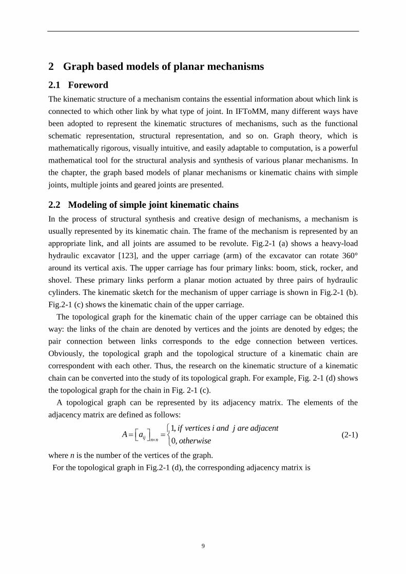
A topological graph can be represented by its adjacency matrix. The elements of the
adjacency matrix are defined as follows:
1,
0,ij n n
if vertices i and j are adjacentA a
otherwise
(2-1)
where n is the number of the vertices of the graph.
For the topological graph in Fig.2-1 (d), the corresponding adjacency matrix is
10
0 1 0 0 1 0 0 0 1 0 1 0
1 0 1 0 0 0 0 0 0 0 0 1
0 1 0 1 0 0 0 0 0 0 0 0
0 0 1 0 1 0 0 0 0 0 0 0
1 0 0 1 0 1 0 0 0 0 0 1
0 0 0 0 1 0 1 0 0 0 0 0=
0 0 0 0 0 1 0 1 0 0 0 0
0 0 0 0 0 0 1 0 1 0 0 0
1 0 0 0 0 0 0 1 0 1 0 0
0 0 0 0 0 0 0 0 1 0 1 0
1 0 0 0 0 0 0 0 0 1 0 0
0 1 0 0 1 0 0 0 0 0 0 0
A
(2-2)
Shovel
Stick
Rocker
Boom
Upper carriage
12
4
123
9
5
76
8
11
10
(a) A heavy-load hydraulic excavator (b) the kinematic sketch of its upper carriage
1
2
3
4
56
7
8
9
10
11
12
12
3
4
5
67
8
9
10
11
12
(c) the kinematic chain, (d) the topological graph, and (e) the contracted graph
Fig. 2-1 Mechanism and its representation graphs
The contracted graph can be obtained by replacing each alternating sequence of binary
vertices and edges by an edge from its topological graph. For example, Fig.2-1 (e) is the
contracted graph for the graph in Fig.2-1 (d).
A contracted graph can also be represented by its adjacency matrix. The elements of the
adjacency matrix for a contracted graph are defined as follows:
11
if vertices and are adjacent
if vertex
0 otherwisem m
ij N N
k , i j through k edges
A a s, i has s selfloops
,
(2-3)
where Nm is the number of the vertices of the contracted graph. The adjacency matrix of the
contracted graph in Fig.2-1(e) is
0 2 1 1
2 0 1 0=
1 1 0 2
1 0 2 0
A
(2-4)
In a contracted graph, two vertices are said to have k-1 multiple-edges if they are connected
directly through k (k>1) edges. The number of multiple-edges for a contracted graph is
defined as the sum of the numbers of multiple-edges between every pair of vertices. For
example, Fig.2-1(e) has two multiple-edges.
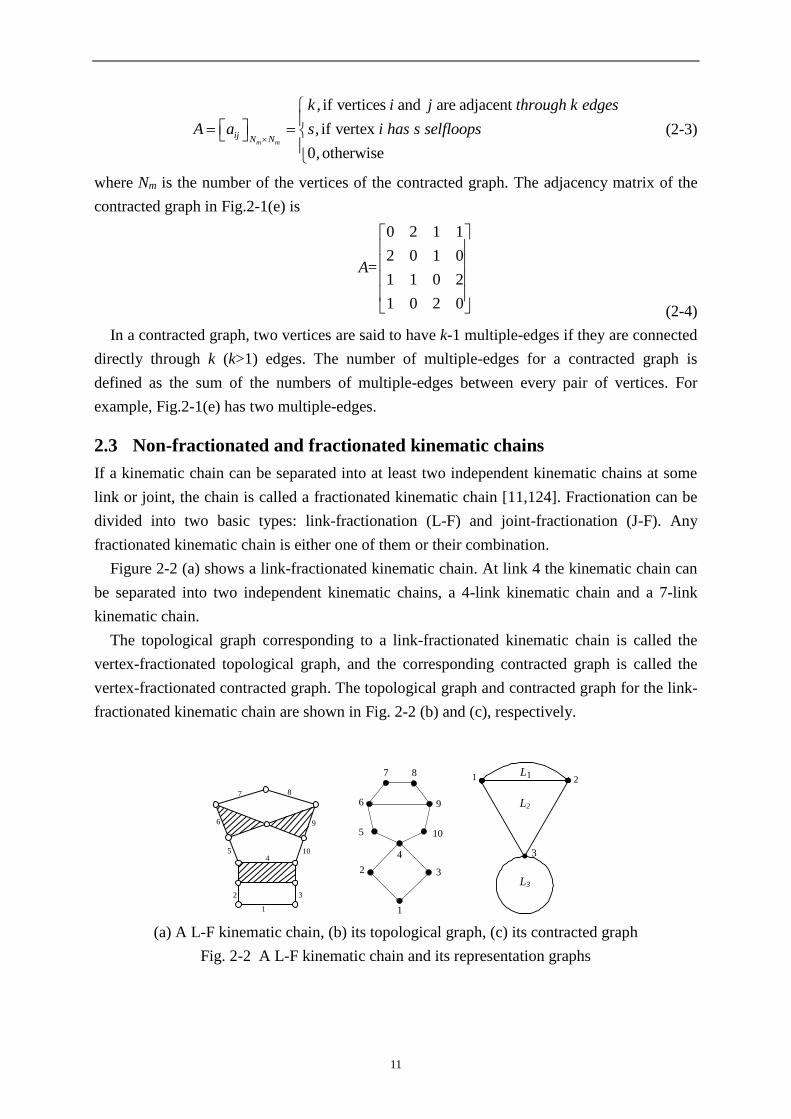
2.3 Non-fractionated and fractionated kinematic chains
If a kinematic chain can be separated into at least two independent kinematic chains at some
link or joint, the chain is called a fractionated kinematic chain [11,124]. Fractionation can be
divided into two basic types: link-fractionation (L-F) and joint-fractionation (J-F). Any
fractionated kinematic chain is either one of them or their combination.
Figure 2-2 (a) shows a link-fractionated kinematic chain. At link 4 the kinematic chain can
be separated into two independent kinematic chains, a 4-link kinematic chain and a 7-link
kinematic chain.
The topological graph corresponding to a link-fractionated kinematic chain is called the
vertex-fractionated topological graph, and the corresponding contracted graph is called the
vertex-fractionated contracted graph. The topological graph and contracted graph for the link-
fractionated kinematic chain are shown in Fig. 2-2 (b) and (c), respectively.
87
96
1054
32
1
4
2 3
1
10
9
8
5
7
6
L1
L3
1 2
L2
3
(a) A L-F kinematic chain, (b) its topological graph, (c) its contracted graph
Fig. 2-2 A L-F kinematic chain and its representation graphs

12
Figure 2-3 (a) shows a joint-fractionated kinematic chain. At joint e the kinematic chain can
be separated into two independent kinematic chains, a 4-link kinematic chain and a 6-link
kinematic chain.
The topological graph corresponding to a joint-fractionated kinematic chain is called the
edge-fractionated topological graph, and the corresponding contracted graph is called the
edge-fractionated contracted graph. The topological graph and contracted graph for the joint-
fractionated kinematic chain are shown in Fig. 2-3 (b) and (c), respectively.
5
10
97
6
4
32
8
1
e
4
2 3
1
10
9
8
5
7
6
12
3
L2 L3
L1
(a) A J-F kinematic chain, (b) its topological graph, (c) its contracted graph
Fig. 2-3 A J-F kinematic chain and its representation graphs
Obviously, fractionated kinematic chains can be synthesized through the combination of
two or more independent non-fractionated kinematic chains.
2.4 Modeling of multiple joint kinematic chains
Many mechanisms contain multiple or compound joints for the sake of simplifying kinematic
analysis and minimizing the space requirement. Studying simple joint kinematic chains using
the above topological graph technique is very convenient. However, this technique cannot be
applied directly to multiple joint kinematic chains because the resulting topological graphs
contain polygons. Therefore, the topological structure of multiple joint kinematic chains is
usually represented by a bicolor topological graph.
Conventional bicolor graphs are established as follows: solid (“●”) and hollow (“○”)
vertices are used to represent links and joints, respectively, and the corresponding solid and
hollow vertices are connected with an edge when a link is connected with a joint [86]. For
example, Fig.2-4 (a) shows an eight-link multiple joint kinematic chain, and Fig.2-4 (b) shows
its conventional bicolor topological graph.
A multiple joint kinematic chain and its conventional bicolor topological graph are also
correspondent with each other. However, a conventional bicolor topological graph has too
many vertices relative to its number of links (its number of vertices is equal to the sum of the
numbers of links and joints of the chain). Therefore, more storage space is needed in the
process of computerized structural synthesis. Moreover, conventional bicolor topological
graphs fail to bridge the studies on simple joint chains and multiple joint chains. Thus, it is

13
hard to employ the studies on the structural analysis and synthesis theory of simple joint
kinematic chains in the studies on kinematic chains with multiple joints.
Here, based on the topological graphs of simple joint kinematic chains, a new kind of
bicolor topological graph is proposed to represent the topological structures of multiple joint
kinematic chains. In the new graph, solid (“●”) and hollow (“○”) vertices denote the links of
the chain and multiple joints, respectively. The two corresponding solid vertices are
connected with an edge if the two links are connected directly by a simple joint, and the
corresponding solid and hollow vertices are connected with an edge if a link is connected with
a multiple joint. For example, Fig.2-4 (c) shows the new bicolor topological graph for the
chain in Fig.2-4 (a). Obviously, a multiple joint kinematic chain and its new bicolor
topological graph are also correspondent with each other.
c
2
b
g
i
f
h
e
da
6
8
7
3
4
51
h
8
i
65
d
4
c3
2
b g
7
f
a
e1
(a) (b)
9(e)
1
5
8
6
7
4
32
2
9 5
8
6
7
4
3
1
(c) (d)
Fig.2-4 (a) A multiple joint kinematic chain, and its (b) conventional bicolor topological
graph, (c) new bicolor topological graph, and (d) basic topological graph
The new bicolor topological graph can be represented by the adjacency matrix modified
from that of the simple joint kinematic chain. The elements of the adjacency matrix are
1,
- ,
0,
ij n n
if vertices i and j are adjacent
A a d if i j and i (or j ) is the label of a hollow vertex
otherwise
(2-5)
where n is the number of the vertices of the graph, and d is the pseudo-degree of the hollow
vertices (The pseudo-degree of a hollow vertex is equal to the number of edges connected
with the hollow vertex).
The adjacency matrix of the topological graph in Fig.2-4 (c) is

14
0 1 0 0 0 0 0 0 1
1 0 1 0 0 0 0 0 0
0 1 0 1 0 0 1 0 0
0 0 1 0 1 0 0 1 0
A 0 0 0 1 0 0 0 0 1
0 0 0 0 0 0 1 1 1
0 0 1 0 0 1 0 0 0
0 0 0 1 0 1 0 0 0
1 0 0 0 1 1 0 0 3
(2-6)
The characteristics of the new bicolor topological graph for a multiple joint kinematic
chain are as follows.
(1) In a new bicolor topological graph, the number of vertices is equal to the sum of the
numbers of links and multiple joints. This number is reduced noticeably compared with that
of the conventional graph.
(2) The degree of any solid vertex is equal to the number of joints connected with the
corresponding link. The pseudo-degree of a hollow vertex is greater than two, and is one more
than the factors of the multiple joint. The factors of a multiple joint are the number of the
kinematic pairs presented by the joint.
(3) For a multiple joint kinematic chain of N links and M kinematic pairs encompassing J
multiple joints, the number of vertices and edges of its new bicolor topological graph are (N+J)
and (M+J), respectively. Both numbers are thus increased by J compared with the number of
links and kinematic pairs of its structural diagram.
For example, Fig.2-4 (c) is the new bicolor topological graph of the eight-link kinematic
chain with one multiple joint in Fig.2-4 (a). Only one multiple joint exists in this kinematic
chain; thus, the numbers of vertices and edges of its new bicolor topological graph [Fig.2-4(c)]
are 9 and 11, respectively.
If the difference between the solid vertex and the hollow vertex is ignored, then the new
bicolor topological graph is converted to the topological graph of simple joint kinematic
chains, which is termed the basic topological graph of the multiple joint kinematic chain. For
example, Fig.2-4 (d) is the basic topological graph of the multiple joint kinematic chain in
Fig.2-4 (a).
2.5 Modeling of geared kinematic chains
A geared mechanism is a complex mechanical system including simple joints, multiple joints,
and geared pairs. This system is obtained by adding a series of meshing gears to a basic
kinematic chain of planar or spatial linkages.
Generally, the topological structure of the geared kinematic chain is represented by a
tricolor topological graph. In conventional tricolor topological graphs [86], solid vertices (“●”)
represent links, hollow vertices (“○”) represent joints, bicyclic vertices (“◎”) represent

15
geared pairs, and vertices are connected with edges according to the relationship of the
corresponding parts in the geared chain.
Fig.2-5 (a) shows a six-link geared chain with two multiple joints and two gear pairs,
obtained by adding two pairs of meshing gears to a four-link linkage. Fig. 2-5 (b) shows the
conventional tricolor topological graph of Fig. 2-5 (a).
The conventional tricolor topological graph is correspondent with its geared kinematic
chain, but it is too complex because the number of its vertices is equal to the sum of the
numbers of links, joints (simple and multiple joints), and geared pairs. Moreover, the
conventional tricolor topological graph is hard to associate with the above two kinds of
kinematic chains.
Here, based on the topological graph of simple joint kinematic chains and the new bicolor
topological graph of multiple joint kinematic chains, the new topological graph of geared
kinematic chains is proposed.
4
1
2
3
d
cb
a
f
e 5
6
3c
2
b
5
e f
6
da
1
4
(a) (b)
1
e
37(c)
2
8(d)4
6
5
f
1
8
3
26
7
5
4
(c) (d)
Fig.2-5 (a) A geared kinematic chain and its (b) conventional tricolor topological graph, (c)
new topological graph, and (d) basic topological graph
(1) Solid vertices (“●”) are used to denote links of the chain, and hollow vertices (“○”) are
used to denote multiple joints.
(2) Dashed lines (“--”) are used to denote geared or cam pairs, and solid lines (“-”) are
used to denote other joints of the chain.
For example, Fig. 2-5 (c) shows the new topological graph of the geared chain in Fig. 2-5
(a). Obviously, a geared chain and its new topological graph are also correspondent.

16
The new topological graph of the geared kinematic chain can also be represented by the
adjacency matrix modified from that of the simple/multiple joint kinematic chain. The
elements of the adjacency matrix are
1,
-1,
- ,
0,
ij n n
if vertices i and j are connected by a solid line
if vertices i and j are connected by a dashed lineA a
d if i j and i(or j) is the label of a hollow vertex
otherwise
(2-7)
where n is the number of vertices of the graph, and d is the pseudo-degree of the hollow
vertices.
For the topological graph in Fig. 2-5 (c), its adjacency matrix is
0 1 0 1 1 0 0 0
1 0 0 0 0 0 1 0
0 0 0 0 0 0 1 1
1 0 0 0 0 0 0 1A
1 0 0 0 0 1 1 0
0 0 0 0 1 0 0 1
0 1 1 0 1 0 3 0
0 0 1 1 0 1 0 3
(2-8)
6 5 4
3
2
1
3
6
7
5
4
2
1
6
5
43
1
2
7
(a) A geared kinematic chain (b) the new topological graph (c) the basic topological
graph
Fig.2-6 A geared kinematic chain and its representation graph
Another geared kinematic chain is shown in Fig. 2-6 (a), and Fig.2-6 (b) is its new
topological graph. The adjacency matrix of the new topological graph is

17
0 1 0 0 0 0 1
1 0 1 1 0 0 0
0 1 0 0 1 0 1
A 0 1 0 0 1 0 1
0 0 1 1 0 1 0
0 0 0 0 1 0 1
1 0 1 1 0 1 4
(2-9)
The characteristics of the new topological graph of the geared chain are:
(1) The number of vertices of the new topological graph is equal to the sum number of links
and multiple joints. This number is reduced remarkably compared with the number of vertices
in the conventional tricolor graph.
(2) The degree of any solid vertex is equal to the number of joints connected with the
corresponding link. The pseudo-degree of every hollow vertex is greater than two, and is one
more than the number of the corresponding kinematic pair.
(3) For a geared kinematic chain with J multiple joints and P geared (or cam) pairs, both
the numbers of vertices and edges of its new topological graph increase by J compared with
the numbers of links and kinematic pairs of its structural diagram.
For example, the kinematic chain shown in Fig. 2-5 (a) has two multiple joints and two
geared pairs. Its new topological graph has 8 and 10 vertices and edges, respectively. Both
increase by two compared with the numbers of links and kinematic pairs of its structural
diagram.
If the difference between the solid vertices and hollow vertices as well as that between dash
lines and solid lines is ignored, then the new topological graph representing the geared
kinematic chain is converted into the topological graph of the simple joint kinematic chain,
which is termed the basic topological graph of the geared kinematic chain. For example,
Fig.2-6 (c) is the basic topological graph of the geared kinematic chain in Fig. 2-6(a).
2.6 Summary
This chapter introduces some basic concepts of the graph theory essential for the
representation of the kinematic structures of planar kinematic chains or mechanisms with
simple joints, multiple joints and geared joints. To facilitate the development of a unified and
automated structural synthesis methodology, the representation models of various planar
mechanisms have close relationships with each other and these relationships are also revealed.

18
19
3 Structural synthesis of non-fractionated contracted graphs
3.1 Foreword
The contracted graph of a kinematic chain shows its primary (or abstract) topological
structure. So the synthesis of contracted graphs is the foundation for the construction of the
kinematic structures of kinematic chains and mechanisms. This chapter attempts to develop a
fully-automatic method to synthesize the whole family of contracted graphs for planar non-
fractionated kinematic chains with all possible degrees of freedom. First the relationships of
non-fractionated contracted graphs for different types of kinematic chains are revealed based
on the parameter 4-bit group and link assortment array. Then a general algorithm for the
generation of the adjacency matrices of contracted graphs from the synthesis equation set is
presented. Efficient methods to detect fractionated structures and isomorphism are also
addressed. Finally, a human-machine interactive synthesis program is developed, and the
complete lists of contracted graphs and valid contracted graphs for planar non-fractionated
kinematic chains with up to 19 links and all possible degrees of freedom are provided.
3.2 4-parameter index of a kinematic family
In the structural analysis and synthesis of kinematic chains, four parameters, namely N
(number of links), F (degrees of freedom), M (number of kinematic pairs), and L (number of
indepentent loops), are the most important and we define the four parameters [N, F, L, M] as
the 4-parameter index of a kinematic family.
According to the Grübler equation and Euler's formula for graphs, we have
MNF 2)1(3 (3-1)
1 NML (3-2)
From Eqs. (3-1) and (3-2), we get
2)1( FNL (3-3)
1 NLM (3-4)
If any two of the four parameters are given, the other two can be determined. For example,
the 4- parameter index for 10-link 1-DOF kinematic chain is [10, 1, 4, 13].
3.3 Link assortment array
The type of links and their number that are necessary to form a kinematic chain with specified
number of links and degrees of freedom are defined as the link assortment. The link
assortment array of a kinematic chain is represented by
[N2, N3, …, Np] (3-5)
where N2, N3, N4, … are the numbers of binary, ternary, quaternary links, etc, in order. If the
number is greater than 9, alphabetic letters are used instead in order to avoid multi-digital
numbers: A represents 10, B represents 11, C represents 12, and so on. For example, the link
20
assortment array [4, A, 0, 0, 0, 0] denotes that the number of ternary links (N3) is 10. The
highest connectivity p is determined by the following two equations
(1)if F1,then 2)1( FNp ;
(2)if F2,then }2)1(),1(min{ FNFNp .
For a kinematic chain for which Nm and Mc are the numbers of vertices and edges,
respectively, of its contracted graph, we have
p
d
dm NN3
(3-6)
and
1 1c mL M N M N (3-7)
Based on graph theory, we have
3
2p
d c
d
d N M
(3-8)
From Eqs. (3-6), (3-7) and (3-8), we have
p
d
dNdL3
)2()1(2 (3-9)
From Eqs. (3-1) and (3-2), we have
12 FLN (3-10)
The number of links in a kinematic chain satisfies
pNNNN 32 (3-11)
From Eqs. (3-9) and (3-10), we have
p
d
dNdFN4
2 )3(3 (3-12)
The link assortment equation for N-link F-DOF kinematic chains can thus be written as
p
p
d
d
NNNN
NdFN
32
4
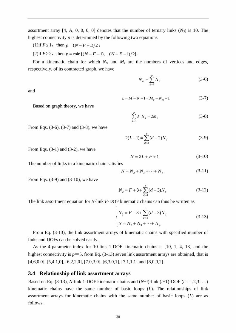
2 )3(3 (3-13)
From Eq. (3-13), the link assortment arrays of kinematic chains with specified number of
links and DOFs can be solved easily.
As the 4-parameter index for 10-link 1-DOF kinematic chains is [10, 1, 4, 13] and the
highest connectivity is p=5, from Eq. (3-13) seven link assortment arrays are obtained, that is
[4,6,0,0], [5,4,1,0], [6,2,2,0], [7,0,3,0], [6,3,0,1], [7,1,1,1] and [8,0,0,2].
3.4 Relationship of link assortment arrays
Based on Eq. (3-13), N-link 1-DOF kinematic chains and (N+i)-link (i+1)-DOF (i = 1,2,3, …)
kinematic chains have the same number of basic loops (L). The relationships of link
assortment arrays for kinematic chains with the same number of basic loops (L) are as
follows.
21
Theorem 3-1: If [N2, N3, …, Np] is a link assortment array for N-link 1-DOF kinematic
chains, then [(N2+1), N3, …, Np, 0] must be a link assortment array for (N+1)-link 2-DOF
kinematic chains, [(N2+2), N3, …, Np, 0, 0] must be a link assortment array for (N+2)-link 3-
DOF kinematic chains, [(N2+3), N3, …, Np, 0, 0, 0] must be a link assortment array for (N+3)-
link 4-DOF kinematic chains, etc.
Proof:
Let [N2, N3, …, Np, Np+1] be a link assortment array for (N+1)-link 2-DOF kinematic
chains, according to link assortment equation (3-13), we have
1321 pp NNNNN (3-14)
and
2 1
4
(1 1) 3 ( 3) ( 2)P
d p
d
N d N p N
(3-15)
Rewriting Eqs. (3-14) and (3-15), we get
132 )1( pp NNNNN (3-16)
and
2 1
4
( 1) 1 3 ( 3) ( 2)P
d p
d
N d N p N
(3-17)
Obviously, if 01 pN , then [N2-1, N3, ..., Np] is a link assortment array for N-link 1-DOF
kinematic chains. So we have proven also that if [N2, N3, …, Np] is a link assortment array for
N-link 1-DOF kinematic chains, then [(N2+1), N3, …, Np, 0] is a link assortment array for
(N+1)-link 2-DOF kinematic chains.
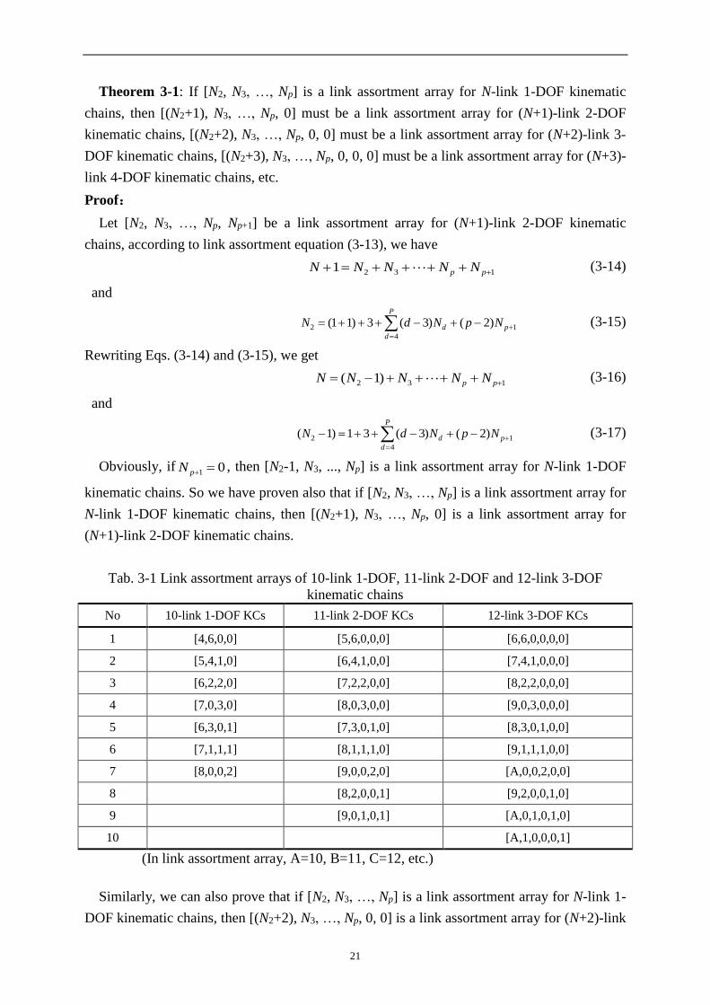
Tab. 3-1 Link assortment arrays of 10-link 1-DOF, 11-link 2-DOF and 12-link 3-DOF
kinematic chains
No 10-link 1-DOF KCs 11-link 2-DOF KCs 12-link 3-DOF KCs
1 [4,6,0,0] [5,6,0,0,0] [6,6,0,0,0,0]
2 [5,4,1,0] [6,4,1,0,0] [7,4,1,0,0,0]
3 [6,2,2,0] [7,2,2,0,0] [8,2,2,0,0,0]
4 [7,0,3,0] [8,0,3,0,0] [9,0,3,0,0,0]
5 [6,3,0,1] [7,3,0,1,0] [8,3,0,1,0,0]
6 [7,1,1,1] [8,1,1,1,0] [9,1,1,1,0,0]
7 [8,0,0,2] [9,0,0,2,0] [A,0,0,2,0,0]
8 [8,2,0,0,1] [9,2,0,0,1,0]
9 [9,0,1,0,1] [A,0,1,0,1,0]
10 [A,1,0,0,0,1]
(In link assortment array, A=10, B=11, C=12, etc.)
Similarly, we can also prove that if [N2, N3, …, Np] is a link assortment array for N-link 1-
DOF kinematic chains, then [(N2+2), N3, …, Np, 0, 0] is a link assortment array for (N+2)-link

22
3-DOF kinematic chains, [(N2+3), N3, …, Np, 0, 0, 0] is a link assortment array for (N+3)-link
4-DOF kinematic chains, etc.
As an example to verify Theorem 3-1, link assortment arrays of 10-link 1-DOF, 11-link 2-
DOF and 12-link 3-DOF kinematic chains are given in Table 3-1. Here, “[4,6,0,0]” is a link
assortment array for 10-link 1-DOF kinematic chains, [(4+1),6,0,0,0] is a link assortment
array for 11-link 2-DOF kinematic chains, and [(4+2),6,0,0,0,0] is a link assortment array for
12-link 3-DOF kinematic chains, etc.
If from a link assortment array at least one non-fractionated contracted graph can be
obtained, the assortment array is defined as a non-fractionated link assortment array;
otherwise, it is a fractionated link assortment array.
Theorem 3-2: The number of non-fractionated link assortment arrays for N-link 1-DOF
kinematic chains and (N+i)-link (i +1)-DOF (i = 1, 2, 3, … ) kinematic chains are the same.
Proof:
If [N2, N3, …, Np, Np+1] is a link assortment array for (N+1)-link 2-DOF kinematic chains,
according to link assortment equation (3-13) we have
1
2 1
4
(1 1) 3 ( 3) ( 3) ( 2)p
d p p
d
N d N p N p N
(3-18)
Obviously, if 1pN =1, then
pN =0. Assume that 1pN =1, and
pN 0, thus based on Eq. (3-
18), we have
1
2
4
( 3) ( 3)( 1)p
d p
d
N N d N p N
(3-19)
and from Eq. (3-19) it would follow NN 2.
Assume now that one has a link assortment array [N2, N3, …, Np-1, 0, 1] (0=pN and
1=1pN ) for (N+1)-link 2-DOF kinematic chains, according to link assortment equation (3-
18), we can conclude that [(N2-3), N3, …, (Np-1+1)] is a link assortment array for (N-2)-link 1-
DOF kinematic chains. The contracted graphs corresponding to [N2, N3, …, Np-1, 0, 1] can be
obtained through the combination of the contracted graphs corresponding to [(N2-3), N3, …,
(Np-1+1)] and a self-loop. Thus all contracted graphs corresponding to [N2, N3, …, Np-1, 0, 1]
are fractionated contracted graphs, containing the same subgraphs as the contracted graphs
corresponding to [(N2-3), N3, …, (Np-1+1)].
Moreover, if for any link assortment array [N2, N3, …, Np, Np+1] of (N+1)-link 2-DOF
kinematic chain it holds 1pN =0, then [N2-1, N3, …, Np] is a link assortment array of N-link 1-
DOF kinematic chains.
So we can conclude that the number of non-fractionated link assortment arrays for N-link
1-DOF kinematic chains and (N+1)-link 2-DOF kinematic chains are the same.
Similarly, we can also prove that the number of non-fractionated link assortment arrays for
N-link 1-DOF kinematic chains and any (N+i)-link (i +1)-DOF (i = 1, 2, 3, … ) kinematic
chains are the same.

23
For example, in Tab. 3-1, 10-link 1-DOF, 11-link 2-DOF and 12-link 3-DOF kinematic
chains have the same number of non-fractionated link assortment arrays. The last two link
assortment arrays, “[8,2,0,0,1]” and “[9,0,1,0,1]”, for 11-link 2-DOF kinematic chains are
fractionated link assortment arrays. The contracted graphs corresponding to “[8,2,0,0,1]” can
be obtained through the combination of the contracted graphs corresponding to link
assortment array [5,2,1] of 8-link 1-DOF kinematic chains and a self-loop. The last three link
assortment arrays for 12-link 3-DOF kinematic chains are also fractionated link assortment
arrays.
3.5 Synthesis equation set of contracted graphs
For a link assortment array [N2, N3, …, Np] of N-link F-DOF kinematic chains, if
0qN (3 q p), then there are Nq vertices whose degrees are all equal to q in the
corresponding contracted graphs. For all 0qN (3 q p) in the link assortment array, the
degrees of all vertices are represented by a degree-array
[d1, d2, …, mNd ] (3-20)
where, Nm is the total number of vertices and didi+1 (i=1, 2, …, (Nm-1)).
For example, [7, 3, 1, 1, 0] is a link assortment array for 12-link 1-DOF kinematic chains.
Here N3=3 0, so there are 3 vertices whose degrees are equal to 3; N4=1 0, so there is 1
vertex whose degree is equal to 4; N5=1 0, so there is 1 vertex whose degree is equal to 5.
The corresponding degree-array is [5, 4, 3, 3, 3].
It is clear that the sum of all elements (xij) in a row in an adjacent matrix is equal to the
degree of corresponding vertex. Based on the adjacency matrices of contracted graphs and the
degree-arrays of link assortment arrays, we have
mmmmmm
m
m
m
NNNNNN
N
N
N
dxxxx
dxxxx
dxxxx
dxxxx
)1(321
33342313
22242312
11141312
...
...
...
...
...
(3-21)
Equation set (3-21) is defined as the synthesis equation set of contracted graphs.
Theorem 3-3: The non-fractionated contracted graphs for N-link 1-DOF kinematic chains
and (N+i)-link (i +1)-DOF (i = 1, 2, 3, … ) kinematic chains are the same.
Proof:
As the degree-array of the link assortment array [N2, N3, …, Np] for N-link 1-DOF
kinematic chains is the same as that of [(N2+1), N3, …, Np, 0] for (N+1)-link 2-DOF kinematic
chains, the non-fractionated contracted graphs for the two types of kinematic chains are the
same. According to Theorem 3-2, the numbers of non-fractionated link assortment arrays for
the two types of kinematic chains are the same. So the non-fractionated contracted graphs for
N-link 1-DOF kinematic chains and (N+1)-link 2-DOF kinematic chains are the same.
Similarly, we can prove that the non-fractionated contracted graphs for N-link 1-DOF
kinematic chains are the same as those for any (N+i)-link (i +1)-DOF (i = 1, 2, 3, … )
24
kinematic chains.
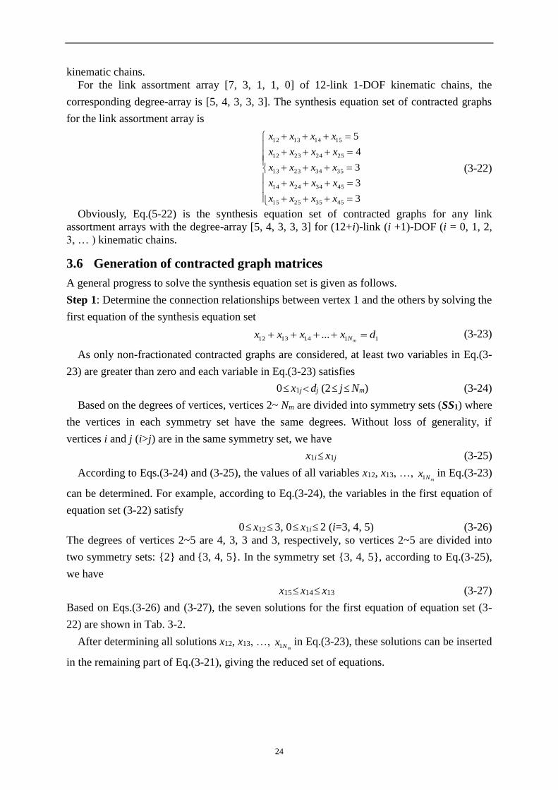
For the link assortment array [7, 3, 1, 1, 0] of 12-link 1-DOF kinematic chains, the
corresponding degree-array is [5, 4, 3, 3, 3]. The synthesis equation set of contracted graphs
for the link assortment array is
3
3
3
4
5
45352515
45342414
35342313
25242312
15141312
xxxx
xxxx
xxxx
xxxx
xxxx
(3-22)
Obviously, Eq.(5-22) is the synthesis equation set of contracted graphs for any link
assortment arrays with the degree-array [5, 4, 3, 3, 3] for (12+i)-link (i +1)-DOF (i = 0, 1, 2,
3, … ) kinematic chains.
3.6 Generation of contracted graph matrices
A general progress to solve the synthesis equation set is given as follows.
Step 1: Determine the connection relationships between vertex 1 and the others by solving the
first equation of the synthesis equation set
11141312 ... dxxxxmN (3-23)
As only non-fractionated contracted graphs are considered, at least two variables in Eq.(3-
23) are greater than zero and each variable in Eq.(3-23) satisfies
0 x1jdj (2 jNm) (3-24)
Based on the degrees of vertices, vertices 2~ Nm are divided into symmetry sets (SS1) where
the vertices in each symmetry set have the same degrees. Without loss of generality, if
vertices i and j (i>j) are in the same symmetry set, we have
x1i x1j (3-25)
According to Eqs.(3-24) and (3-25), the values of all variables x12, x13, …, mNx1
in Eq.(3-23)
can be determined. For example, according to Eq.(3-24), the variables in the first equation of
equation set (3-22) satisfy
0 x123, 0 x1i2 (i=3, 4, 5) (3-26)
The degrees of vertices 2~5 are 4, 3, 3 and 3, respectively, so vertices 2~5 are divided into
two symmetry sets: {2} and {3, 4, 5}. In the symmetry set {3, 4, 5}, according to Eq.(3-25),
we have
x15 x14 x13 (3-27)
Based on Eqs.(3-26) and (3-27), the seven solutions for the first equation of equation set (3-
22) are shown in Tab. 3-2.
After determining all solutions x12, x13, …, mNx1
in Eq.(3-23), these solutions can be inserted
in the remaining part of Eq.(3-21), giving the reduced set of equations.

25
mmmmmm
m
m
NNNNNN
N
N
xdxxx
xdxxx
xdxxx
1)1(32
13333423
12222423
...
...
...
...
(3-28)
Tab. 3-2 The seven solutions for the first equation of equation set (3-22)
No x12 x13 x14 x15
1 3
2 0 0
2 1 1 0
3 2
2 1 0
4 1 1 1
5 1
2 2 0
6 2 1 1
7 0 2 2 1
Step 2: Determine the connection relationships between vertex 2 and the others by solving the
first equation of equation set (3-28)
12222423 ... xdxxxmN (3-29)
Each variable in Eq.(3-29) satisfies
0 x2imin(122 xd , ii xd 1 )(3 iNm) (3-30)
Based on the values of x13, …, mNx1
, vertices 3~ Nm are further divided into new symmetry
sets (SS2). Two vertices m and n are in the same new symmetry set (SS2) if and only if they
belong to the same symmetry set (SS1) in Step 1 and they have the same values of x1m and x1n.
Without loss of generality, if vertices i and j (i>j) are in the same new symmetry set, we have
x2i x2j (3-31)
According to Eqs.(3-30) and (3-31), the values of all variables x23, x24, …, mNx2
in Eq.(3-29)
can be determined. For example, for the first solution in Tab.3-2, equation set (3-22) is
converted into
3
3
1
1
453525
453424
353423
252423
xxx
xxx
xxx
xxx
(3-32)
For the first equation of equation set (3-32), according to Eq.(3-30), we have
0 x2i1 (i=3, 4, 5) (3-33)
As x15=x14 x13, vertices 3, 4 and 5 are divided into two new symmetry sets: {3} and {4, 5}.
According to Eq.(3-31), we have
x25 x24 (3-34)
The two solutions for the first equation in equation set (3-32) are thus: x23=1, x24=0, x25=0 or
x23=0, x24=1, x25=0.

26
After determining all solutions x23, x24, …, mNx2
in Eq.(3-29), these solutions can be
inserted in the remaining part of Eq.(3-28), giving the reduced set of equations.
mmmmmmm
m
m
NNNNNNN
N
N
xxdxxx
xxdxxx
xxdxxx
21)1(43
2414444534
2313333534
...
...
...
...
(3-35)
Step n for 3 n Nm-3: Determine the connection relationships between vertex n and the
others by solving the first equation in Eq. (3-36)
1
1
)1()1(
1
1
)1()1()1()2)(1()1(
1
1
)2()1(
...
...
...
...
n
i
iNNNNNnnN
n
i
ninNnnnnn
n
i
innnNnnnn
mmmmmm
m
m
xdxxx
xdxxx
xdxxx
(3-36)
Each variable of the first equation satisfies
0 xnjmin(
1
1
n
i
inn xd ,
1
1
n
i
ijj xd ) ((n+1) j b) (3-37)
Based on the values of x(n-1)(n+1), …, mNnx )1(
, vertices (n+1)~ Nm are divided into new
symmetry sets (SSn). Two vertices p and q are in the same new symmetry set (SSn) if and
only if they belong to the same symmetry set (SSn-1) in Step (n-1) and they have the same
values of x(n-1)p and x(n-1)q. Without loss of generality, if vertices i and j (i>j) are in the same
symmetry set SSn, we have
xni xnj (3-38)
According to Eqs.(3-37) and (3-38), the values of all variables xn(n+1), xn(n+2), …,mnNx in the
first equation of Eq. (3-36) can be determined.
Step (Nm-2) [final step]: The synthesis equation set is converted into the following form at
the last step.
3
( 2)( 1) ( 2) ( 2) ( 2)
1
3
( 2)( 1) ( 1) ( 1) ( 1)
1
3
( 2) ( 1)
1
m
m m m m m m
m
m m m m m m
m
m m m m m m
N
N N N N N i N
i
N
N N N N N i N
i
N
N N N N N iN
i
x x d x
x x d x
x x d x
(3-39)
If Eq. (3-39) has a solution, then it is a contracted graph matrix; otherwise, there is no
contracted graph corresponding to the link assortment array. In order to obtain all the
contracted graphs without fractionated and isomorphic structures, the detection of fractionated
structure and isomorphism is necessary.
27
3.7 Identification of fractionated structures
Fractionated mechanisms or kinematic chains can be synthesized through combination of
several mechanisms or kinematic chains of non-fractionated structures, so only the contracted
graphs of non-fractionated structures are considered in the synthesis process. Below the loop
based method is proposed to detect both isomorphic and fractionated structures.
Among all the loops of a graph, a loop comprising the largest number of vertices or edges
is defined as its maximum loop. For a maximum loop, one can define the set of degree
sequences of the loop as the sequences of degrees of contiguous vertices either in clockwise
or in counter-clockwise direction, starting at any vertex. Thus there will be 2k degree
sequences for a loop with k vertices. Each degree sequence can be viewed as a number. The
largest number of a degree sequence corresponding to a maximum loop is defined as the
canonical perimeter degree-sequence and the corresponding loops are defined as the
perimeter loops (one or several) .
If the following conditions (1) and (2) are satisfied, then the graph contains a vertex-
fractionated structure:
(1) There exists a loop with only one shared vertex with any one of the perimeter loops.
(2) The other vertices in the loop are not adjacent with the vertices on the perimeter loop.
If the following (1) and (2) are both satisfied, then the graph contains an edge-fractionated
structure:
(1) There exists a loop which has no shared vertex with any one of the perimeter loops.
(2) Only one vertex in the loop is adjacent with the vertices on the perimeter loop.
For all the synthesized connected graphs, after those with vertex-fractionated or edge-
fractionated structures are deleted, the rest are those with non-fractionated contracted graphs.
3.8 Unique representation of contracted graphs[114]
The problem of isomorphism identification is one of the most difficult problems in structural
synthesis. Based on the loops of kinematic chains, the technique of unique representation of
graphs was developed to detect isomorphism between graphs of kinematic chains[114]. Here,
we briefly summarise our previous work of unique representation of graphs [114] for better
understanding in the present context.
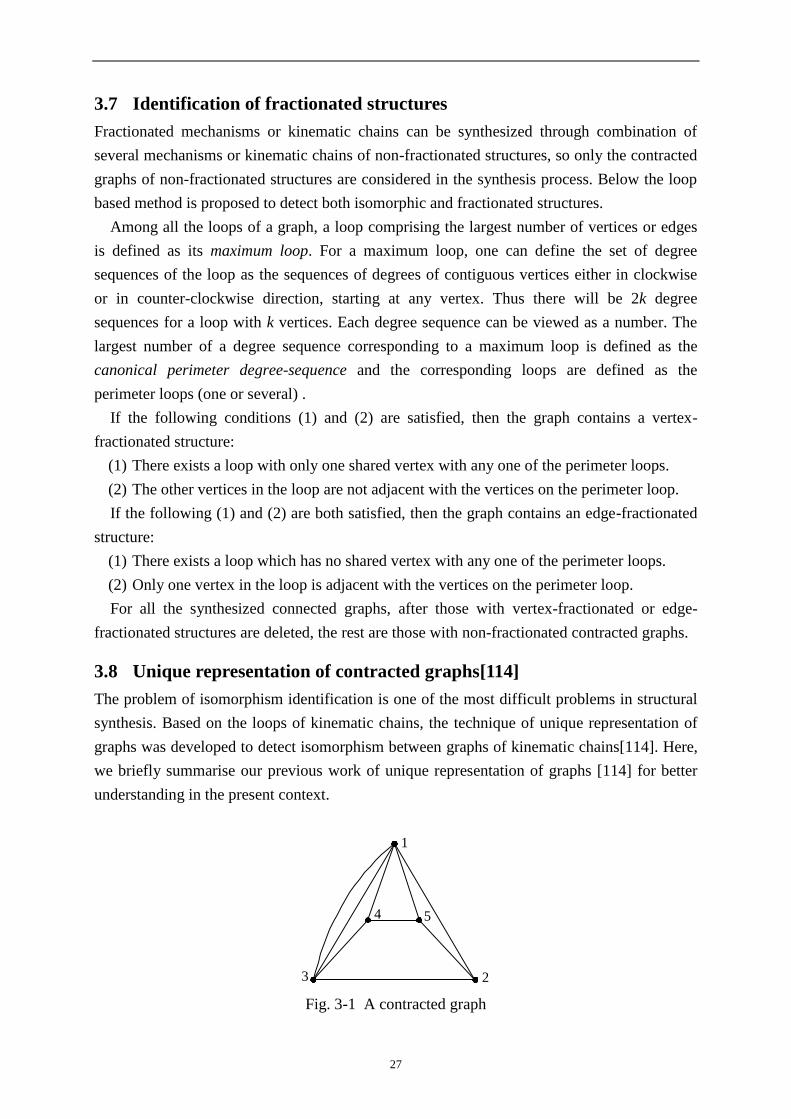
1
23
4 5
Fig. 3-1 A contracted graph

28
Step 1: Obtain the perimeter loops of a contracted graph.
In a contracted graph, the loops with the most vertices or edges are defined as its maximum
loops. For example, the contracted graph in Fig. 3-1 has two maximum loops: the first is
constituted by vertices 1,3,2,5,4 and the second is by vertices 1,3,4,5,2.
The degree-sequence of a maximum loop is the degree permutation of vertices sequenced
one by one from a starting vertex along the loop clockwise or counterclockwise. In Fig. 3-1
the degree-sequence for the first maximum loop is 54333, and the degree-sequence for the
second is also 54333.
A degree-sequence can be viewed as a number. For a contracted graph, the largest of the
degree-sequences of the maximum loops is defined as the canonical perimeter degree-
sequence and the corresponding loop is defined as the perimeter loop. Obviously, both
maximum loops are perimeter loops in Fig. 3-1.
Step 2: Obtain the perimeter graph.
The perimeter graph of a contracted graph is drawn as follows.
(1) Draw the perimeter loop as the outmost loop in the form of an equilateral polygon.
(2) Put the remaining vertices of the graph inside the perimeter loop.
For example, the two perimeter graphs corresponding to the two perimeter loops in Fig. 3-1
are shown in Fig. 3-2.
1
3
25
4
1
3
45
2
(a) (b)
Fig. 3-2 The two perimeter graphs for Fig. 3-1
Step 3: Obtain the canonical perimeter graphs and canonical adjacency matrices.
(1)Assign natural numbers 1~t in turn to each vertex as its label on the perimeter loop
according to the canonical perimeter degree-sequence.
(2) In a perimeter loop, if the canonical perimeter degree-sequence can be obtained by
counting from different starting vertices, any vertex connected to the inner sub-chain with the
most vertices is selected as the starting vertex.
(3) Relabel the vertices on inner sub-chains according to their degrees: the vertices with the
bigger degrees are relabeled first.
The perimeter graph labeled in the above way is defined as the canonical perimeter graph.
The corresponding adjacency matrix is defined as the canonical adjacency matrix. The

29
canonical perimeter graphs for Figs. 3-2(a) and (b) are the same, and their shared canonical
perimeter graph is shown in Fig. 3-3.
1
2
34
5
Fig. 3-3 The shared canonical perimeter graph for the two graphs in Fig. 3-2
Step 4: Obtain characteristic number string.
From a contracted graph, the matrix with the largest value of the number string
concatenated by the upper-right triangle of the matrix among the canonical adjacency
matrices is defined as the characteristic adjacency matrix (CAM), and the corresponding
canonical perimeter graph is defined as the characteristic perimeter contracted
graph(CPCG).
Obviously, the characteristic adjacency matrix of a contracted graph is unique. The number
string concatenated by the upper-right triangle of the characteristic adjacency matrix is
defined as the characteristic number string (CNS), which is used to identify isomorphism in
the synthesis process.
1 2
3
4
56
7
8 9
1011
1
2
3
45
6
7
8
9
10
11
1 2
3
4
56
7
8
91011
(a) (b) (c)
Fig. 3-4 Three contracted graphs
1
2
3
4
5
67
8
9
10
11
1
2
3
4
5
6
7
8
9
10
11
(a) (b)
Fig. 3-5 (a) The shared CPCG of Fig. 3-4 (a) and (b), (b) the CPCG of Fig. 3-4 (c)

30
As only one canonical perimeter graph exists for the contracted graph in Fig. 3-1, the
canonical perimeter graph is also the characteristic perimeter contracted graph. The
characteristic adjacency matrix and characteristic number string of the contracted graph in
Fig. 3-1 are
01011
10101
01011
10102
11120
CAM (3-53)
CNS = 2111101101 (3-54)
Three contracted graphs are shown in Fig. 3-4. The characteristic number strings for these
contracted graphs are as follows.
CNS (a) = 1010100001100000100100100001000000101000100001000100102
CNS (b) = 1010100001100000100100100001000000101000100001000100102 (3-55)
CNS (c) = 1010100001100001000100100001000000100100100001000100102
As CNS (a) = CNS (b) CNS (c), it is clear that the contracted graphs in Figs. 3-4(a) and (b)
are isomorphic, and Fig. 3-4(c) is a different contracted graph. The shared characteristic
perimeter contracted graph for Figs. 3-4(a) and (b) are shown in Fig. 3-5 (a), and Fig. 3-5(b) is
the characteristic perimeter contracted graph for Fig. 3-4 (c).
3.9 Synthesis results
Based on the above method, a synthesis program has been developed in Visual C++6.0. With
the program, the one contracted graph for 6-link 1-DOF kinematic chains, all the four
contracted graphs for 8-link 1-DOF kinematic chains, all the 17 contracted graphs for 10-link
1-DOF kinematic chains, all the 118 contracted graphs for 12-link 1-DOF kinematic chains,
all the 1198 contracted graphs for 14-link 1-DOF kinematic chains, all the 17072 contracted
graphs for 16-link 1-DOF kinematic chains, and all the 309147 contracted graphs for 18-link
1-DOF kinematic chains are synthesized.
Tab. 3-3 Synthesis results for the contracted graphs of 1-DOF kinematic chains
No. of links No. of basic loops No. of synthesized
contracted graphs Computation time
6 2 1 -
8 3 4 -
10 4 17 -
12 5 118 48(ms)
14 6 1198 1.657(s)
16 7 17072 57.846(s)
18 8 309147 1h37m
31
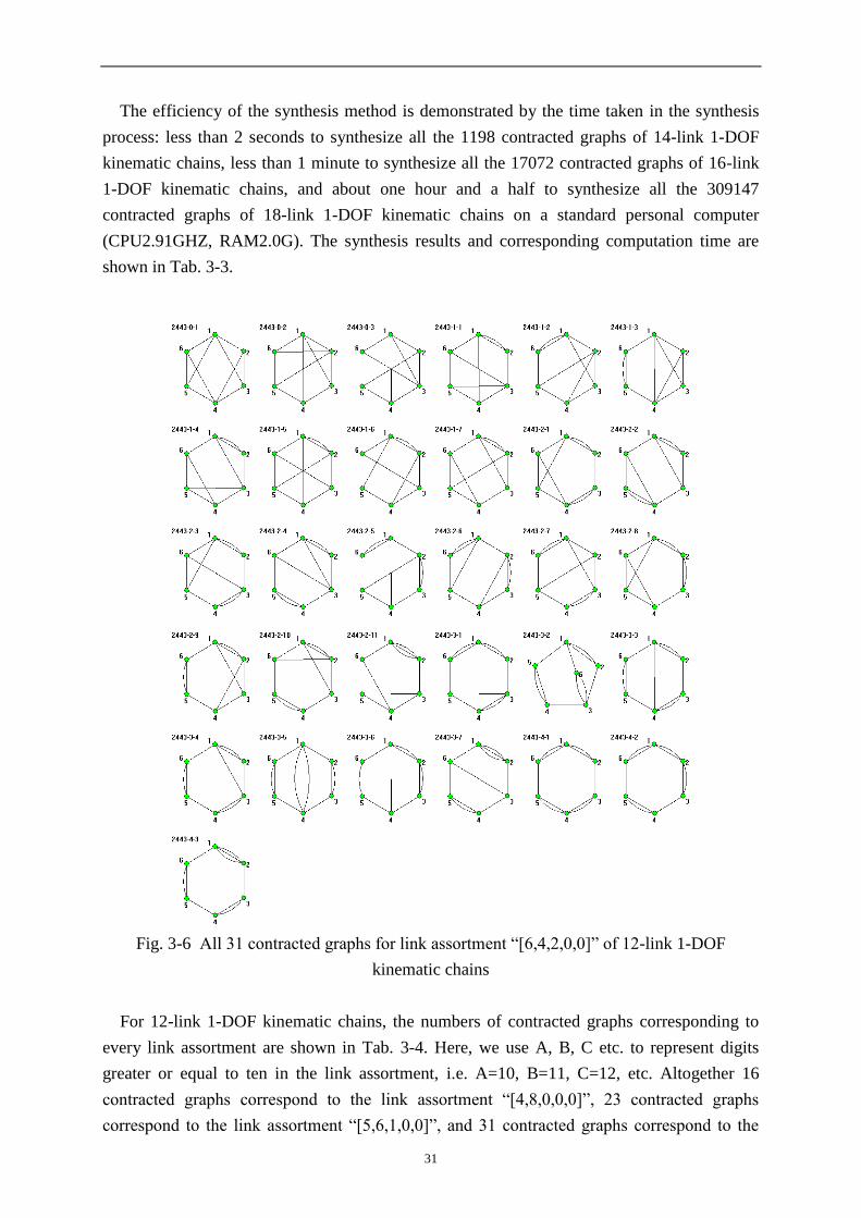
The efficiency of the synthesis method is demonstrated by the time taken in the synthesis
process: less than 2 seconds to synthesize all the 1198 contracted graphs of 14-link 1-DOF
kinematic chains, less than 1 minute to synthesize all the 17072 contracted graphs of 16-link
1-DOF kinematic chains, and about one hour and a half to synthesize all the 309147
contracted graphs of 18-link 1-DOF kinematic chains on a standard personal computer
(CPU2.91GHZ, RAM2.0G). The synthesis results and corresponding computation time are
shown in Tab. 3-3.
Fig. 3-6 All 31 contracted graphs for link assortment “[6,4,2,0,0]” of 12-link 1-DOF
kinematic chains
For 12-link 1-DOF kinematic chains, the numbers of contracted graphs corresponding to
every link assortment are shown in Tab. 3-4. Here, we use A, B, C etc. to represent digits
greater or equal to ten in the link assortment, i.e. A=10, B=11, C=12, etc. Altogether 16
contracted graphs correspond to the link assortment “[4,8,0,0,0]”, 23 contracted graphs
correspond to the link assortment “[5,6,1,0,0]”, and 31 contracted graphs correspond to the

32
link assortment “[6,4,2,0,0]”, etc. For example, the 31 contracted graphs corresponding to link
assortment “[6,4,2,0,0]” are shown in Fig. 3-6. Reading in Fig. 3-6 from left to right and from
top to bottom, the first three contracted graphs have no multiple edges; the 4th to the 10th
contracted graphs have one multiple edge; the 11th to the 21st contracted graphs have two
multiple edges; the 22nd to the 28th contracted graphs have 3 multiple edges; and the last
three contracted graphs have four multiple edges.
If from a contracted graph no valid kinematic chains can be synthesized, the contracted
graph is termed a rigid contracted graph (RCG); otherwise, the contracted graph is termed a
valid contracted graph (VCG). For example in the synthesis of 1-DOF kinematic chains from
the contracted graphs in Fig. 3-6, because N2=6 in the link assortment [6,4,2,0,0] and only six
binary vertices (N2) can be inserted into these contracted graphs, the contracted graphs having
more than three multiple edges between any two vertices (in Fig. 3-6 the contracted graphs
2443-4-1, 2443-4-2 and 2443-4-3) are rigid contracted graphs. Besides, the contracted graphs
2443-3-1 and 2443-3-4 are also rigid contracted graphs.
Tab. 3-4 Classification of contracted graphs for 12-link 1-DOF kinematic chains
No Link Assortment No. of CGs No Link Assortment No. of CGs
1 [4,8,0,0,0] 16 9 [8,2,0,2,0] 4
2 [5,6,1,0,0] 23 10 [9,0,1,2,0] 1
3 [6,4,2,0,0] 31 11 [7,4,0,0,1] 2
4 [7,2,3,0,0] 11 12 [8,2,1,0,1] 2
5 [8,0,4,0,0] 3 13 [9,0,2,0,1] 1
6 [6,5,0,1,0] 7 14 [9,1,0,1,1] 1
7 [7,3,1,1,0] 11 15 [A,0,0,0,2] 1
8 [8,1,2,1,0] 4
In the link assortment, A=10, B=11, C=12, etc.
For 14-link 1-DOF kinematic chains, all 50 contracted graphs for link assortment
“[8,2,4,0,0,0]” are shown in Fig. 3-7. Reading in Fig. 3-7 from left to right and from top to
bottom, the first two have no multiple edges; the 3rd to the 7th graph have one multiple edge;
the 8th to the 21st graph have two multiple edges; the 22nd to the 37th graph have three
multiple edges; the 38th to the 47th graph have four multiple edges; the last three have five
multiple edges. The last three and the 38th, 39th, and 40th contracted graphs are rigid
contracted graphs. The rest 44 are valid contracted graphs.
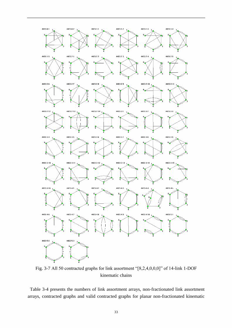
33
Fig. 3-7 All 50 contracted graphs for link assortment “[8,2,4,0,0,0]” of 14-link 1-DOF
kinematic chains
Table 3-4 presents the numbers of link assortment arrays, non-fractionated link assortment
arrays, contracted graphs and valid contracted graphs for planar non-fractionated kinematic

34
chains with N (6 N 19) links and F (1 F 14) degrees of freedom. Because the topological
structures of some kinematic chains, such as 4-link 1-DOF, 5-link 2-DOF, 6-link 3-DOF, 7-
link 4-DOF, are too simple (only a loop), these kinematic chains are not included. The
correctness of theorems 1, 2 and 3 is also verified by the synthesis results in Tab.3-4. The
valid contracted graphs, from which at least one proper kinematic chain can be synthesized,
are also included in the last column of Tab.3-4. So a complete list of contracted graphs and
valid contracted graphs for planar non-fractionated kinematic chains up to 19 links and all
possible degrees of freedom are obtained.
Tab. 3-4 Numbers of contracted graphs and valid contracted graph of non-fractionated
kinematic chains
N F No. of link
assortment arrays
No. of non-fractionated
link assortment arrays
No. of
contracted graphs
No. of valid
contracted graphs
6 1 1 1 1 1
7 2 2 1 1 1
8 1 3 3 4 4
3 2 1 1 1
9 2 4 3 4 4
4 2 1 1 1
10
1 7 7 17 15
3 5 3 4 4
5 2 1 1 1
11
2 9 7 17 16
4 5 3 4 4
6 2 1 1 1
12
1 15 15 118 97
3 10 7 17 17
5 5 3 4 4
7 2 1 1 1
13
2 18 15 118 109
4 11 7 17 17
6 5 3 4 4
8 2 1 1 1
14
1 30 30 1198 923
3 20 15 118 116
5 11 7 17 17
7 5 3 4 4
9 2 1 1 1
15 2 75 30 1198 1090
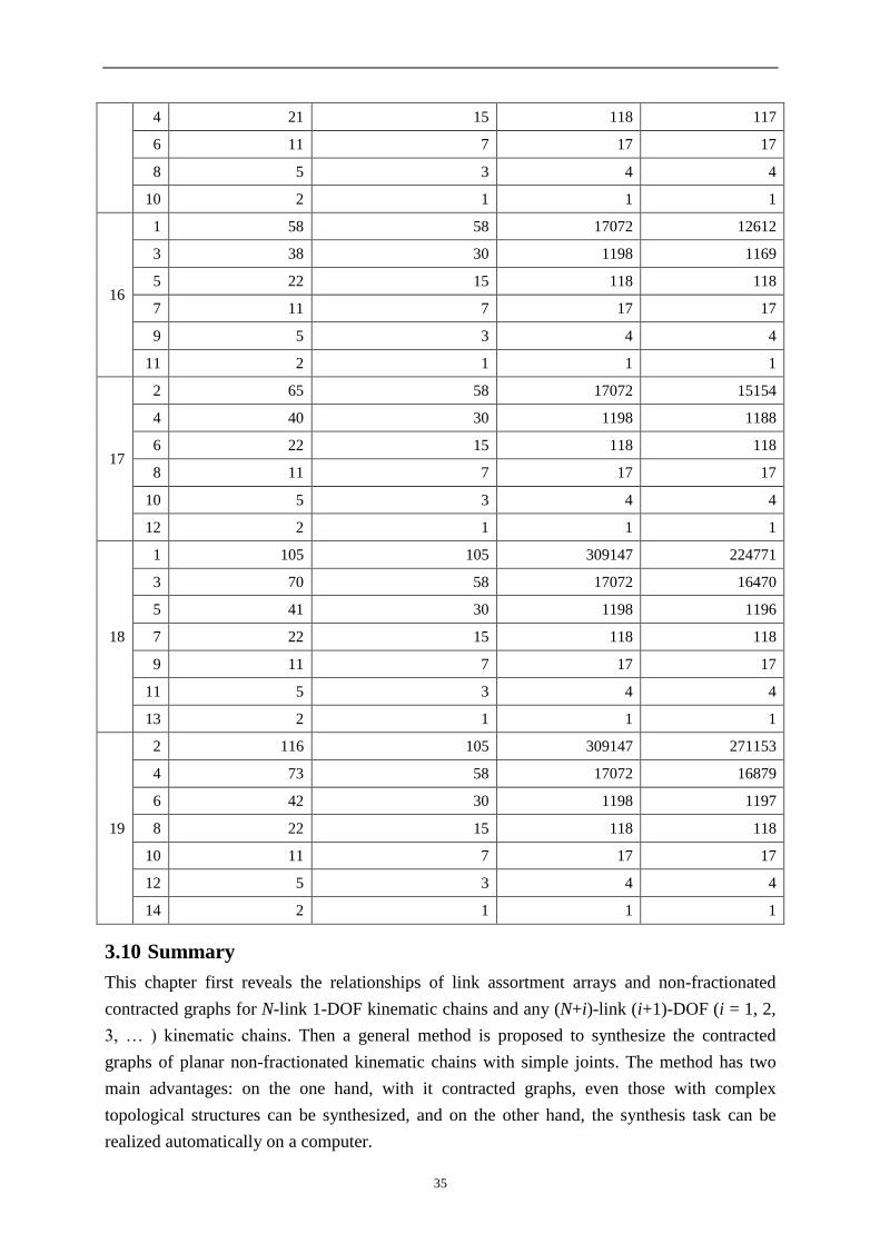
35
4 21 15 118 117
6 11 7 17 17
8 5 3 4 4
10 2 1 1 1
16
1 58 58 17072 12612
3 38 30 1198 1169
5 22 15 118 118
7 11 7 17 17
9 5 3 4 4
11 2 1 1 1
17
2 65 58 17072 15154
4 40 30 1198 1188
6 22 15 118 118
8 11 7 17 17
10 5 3 4 4
12 2 1 1 1
18
1 105 105 309147 224771
3 70 58 17072 16470
5 41 30 1198 1196
7 22 15 118 118
9 11 7 17 17
11 5 3 4 4
13 2 1 1 1
19
2 116 105 309147 271153
4 73 58 17072 16879
6 42 30 1198 1197
8 22 15 118 118
10 11 7 17 17
12 5 3 4 4
14 2 1 1 1
3.10 Summary
This chapter first reveals the relationships of link assortment arrays and non-fractionated
contracted graphs for N-link 1-DOF kinematic chains and any (N+i)-link (i+1)-DOF (i = 1, 2,
3, … ) kinematic chains. Then a general method is proposed to synthesize the contracted
graphs of planar non-fractionated kinematic chains with simple joints. The method has two
main advantages: on the one hand, with it contracted graphs, even those with complex
topological structures can be synthesized, and on the other hand, the synthesis task can be
realized automatically on a computer.

36
For the automatic synthesis, a human-machine interactive synthesis program is developed,
in which just the number of links and degrees of freedom are input, and all the corresponding
link assortment arrays and contracted graphs are synthesized automatically. Contracted graphs
for planar non-fractionated kinematic chains with N (4 N 19) links and F (1 F 14)
degrees of freedom are synthesized with the method.
37
4 Structural synthesis of non-fractionated kinematic chains and
mechanisms
4.1 Foreword
The contracted graph of a kinematic chain is obtained by replacing every binary path with an
edge in the topological graph of the chain. Vice versa, from a contracted graph the
corresponding topological graph of a kinematic chain can be obtained by inserting appropriate
number of binary vertices into the edges of the contracted graph. Although the concept of the
contracted graph in the graph theory had been adopted by many researchers to synthesize
kinematic chains, only those chains consisting of up to 12 links have been previously reported
in literature [5]. This chapter attempts to develop a new fully-automatic method to synthesize
non-fractionated kinematic chains with more complex structures based on the synthesis of
contracted graphs in chapter 3.
4.2 Synthesis requirements
The main aim of structural synthesis of kinematic chains is to serve the conceptual design of
mechanisms by providing the designers with all the candidate kinematic structures of
mechanisms for choice. From the reports in literature, there are more topological structures of
various types as there are species of creatures in the nature. So in order to reach the aim of
structural synthesis, an ideal synthesis method must have the following three characteristics:
(1) Effectiveness. The method generates all the valid topological structures, free from any
wrong structures (no rigid sub-chains) and reduplicate or missing structures (no isomorphic
chains).
(2) Automation. Synthesis can be carried out fully in the computers.
(3) Designer-friendliness. Synthesized topological structures are output in the form of
graphs rather than in the single form of algebraic representations.
Despite the great number of existing synthesis methods, hardly any method meets all the
three requirements above. As pointed out by Al-Dweiri et al in 2010 in MMT [17], “It should
be noted here that, regardless of the method used, a general problem still unsolved in
structural synthesis is the enumeration of a complete list of kinematic chains and mechanisms
without isomorphism and without degenerate chains.” In the following of the chapter, we
introduce an effective, fully-automatic and designer-friendly method for the synthesis of non-
fractionated kinematic chains.
4.3 Synthesis progress
In general, there are many different ways for inserting binary vertices to the edges of a
contracted graph, especially for those with complex structures. Some insertion ways may lead
to resulting kinematic chains containing rigid sub-chains, and some others may lead to
resulting kinematic chains having reduplicate structures. For a given contracted graph, the
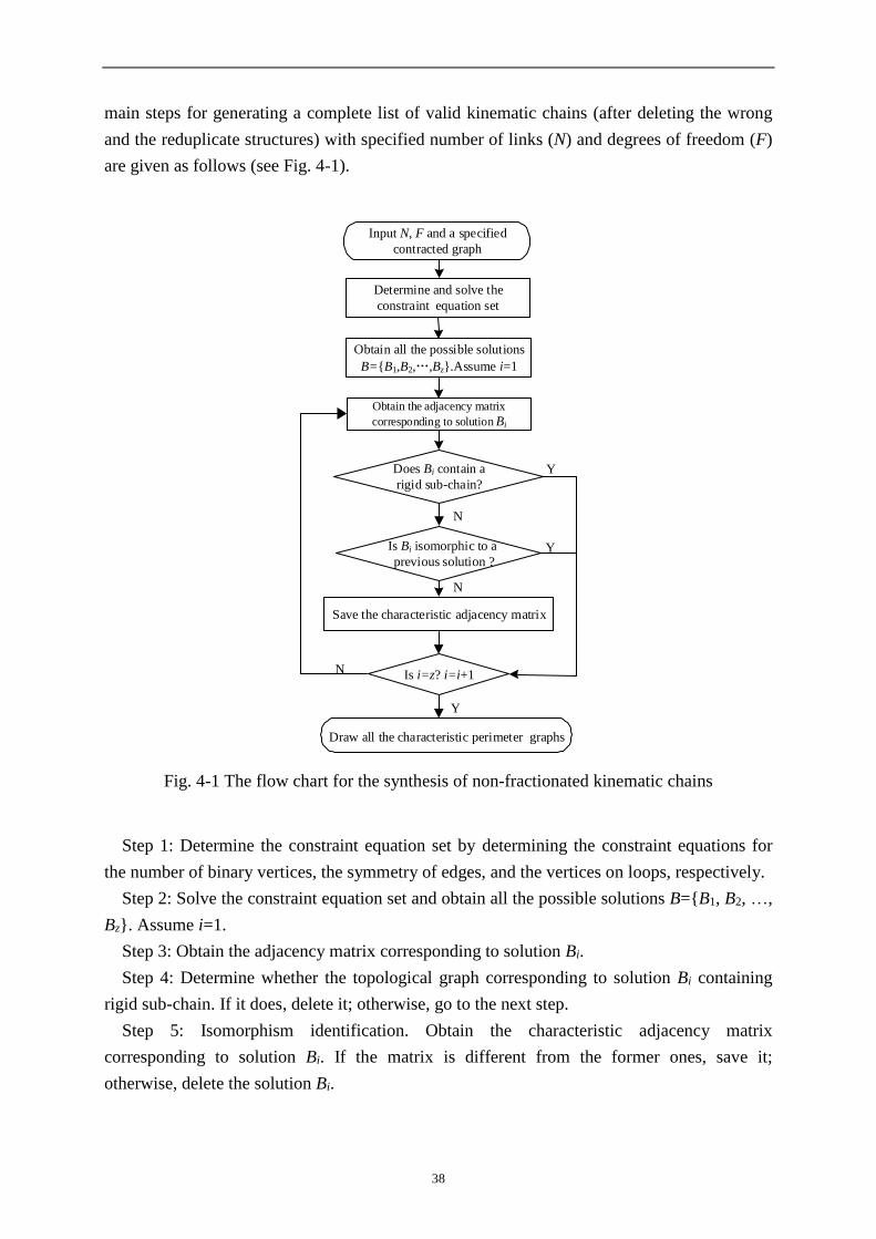
38
main steps for generating a complete list of valid kinematic chains (after deleting the wrong
and the reduplicate structures) with specified number of links (N) and degrees of freedom (F)
are given as follows (see Fig. 4-1).
Input N, F and a specified
contracted graph
Determine and solve the
constraint equation set
Obtain all the possible solutions
B={B1,B2,…,Bz}.Assume i=1
Obtain the adjacency matrix
corresponding to solution Bi
N
N
Y
Draw all the characteristic perimeter graphs
N
Y Is Bi isomorphic to a
previous solution ?
Save the characteristic adjacency matrix
Is i=z? i=i+1
Does Bi contain a
rigid sub-chain?
Y
Fig. 4-1 The flow chart for the synthesis of non-fractionated kinematic chains
Step 1: Determine the constraint equation set by determining the constraint equations for
the number of binary vertices, the symmetry of edges, and the vertices on loops, respectively.
Step 2: Solve the constraint equation set and obtain all the possible solutions B={B1, B2, …,
Bz}. Assume i=1.
Step 3: Obtain the adjacency matrix corresponding to solution Bi.
Step 4: Determine whether the topological graph corresponding to solution Bi containing
rigid sub-chain. If it does, delete it; otherwise, go to the next step.
Step 5: Isomorphism identification. Obtain the characteristic adjacency matrix
corresponding to solution Bi. If the matrix is different from the former ones, save it;
otherwise, delete the solution Bi.
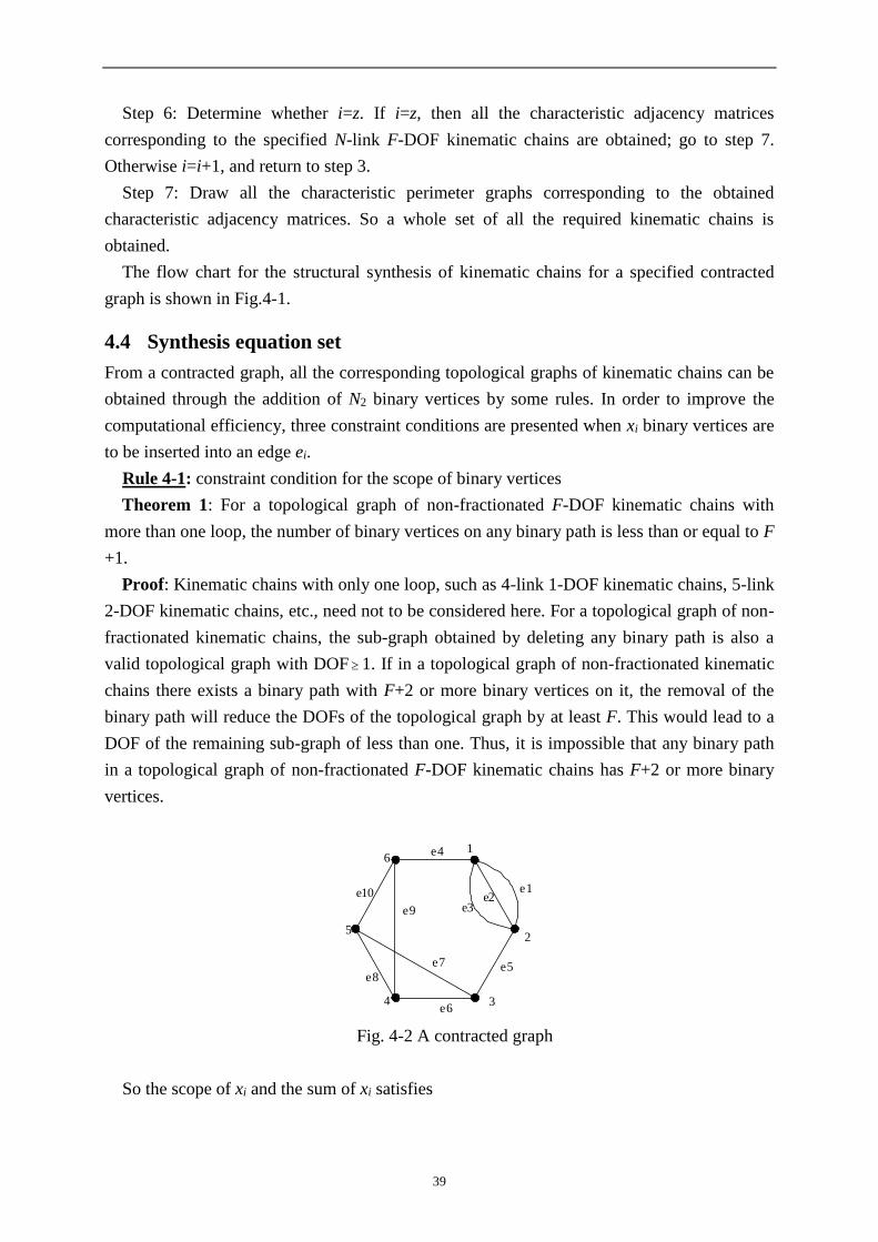
39
Step 6: Determine whether i=z. If i=z, then all the characteristic adjacency matrices
corresponding to the specified N-link F-DOF kinematic chains are obtained; go to step 7.
Otherwise i=i+1, and return to step 3.
Step 7: Draw all the characteristic perimeter graphs corresponding to the obtained
characteristic adjacency matrices. So a whole set of all the required kinematic chains is
obtained.
The flow chart for the structural synthesis of kinematic chains for a specified contracted
graph is shown in Fig.4-1.
4.4 Synthesis equation set
From a contracted graph, all the corresponding topological graphs of kinematic chains can be
obtained through the addition of N2 binary vertices by some rules. In order to improve the
computational efficiency, three constraint conditions are presented when xi binary vertices are
to be inserted into an edge ei.
Rule 4-1: constraint condition for the scope of binary vertices
Theorem 1: For a topological graph of non-fractionated F-DOF kinematic chains with
more than one loop, the number of binary vertices on any binary path is less than or equal to F
+1.
Proof: Kinematic chains with only one loop, such as 4-link 1-DOF kinematic chains, 5-link
2-DOF kinematic chains, etc., need not to be considered here. For a topological graph of non-
fractionated kinematic chains, the sub-graph obtained by deleting any binary path is also a
valid topological graph with DOF 1. If in a topological graph of non-fractionated kinematic
chains there exists a binary path with F+2 or more binary vertices on it, the removal of the
binary path will reduce the DOFs of the topological graph by at least F. This would lead to a
DOF of the remaining sub-graph of less than one. Thus, it is impossible that any binary path
in a topological graph of non-fractionated F-DOF kinematic chains has F+2 or more binary
vertices.
1
2
34
5
6
e1e2
e3
e4
e5
e6
e8
e10
e9
e7
Fig. 4-2 A contracted graph
So the scope of xi and the sum of xi satisfies

40
10
2
1
Fx
Nx
i
t
i
i (4-1)
where t is the total number of the edges of the contracted graph.
For example, if the contracted graph in Fig. 4-2 is used to synthesize 12-link 1-DOF
kinematic chains, based on rule 4-1, we have
20
610
1
i
i
i
x
x (4-2)
Rule 4-2: Constraint condition for the symmetry of edges
For k parallel edges ei, ei+1, ..., ei+k-1 connecting directly one single pair of vertices (Vp and
Vq), without loss of generality, assume 11 kiii xxx .
(1)If vertices Vp and Vq are connected with two different vertices in the contracted graph,
the number of binary vertices to be inserted into these parallel edges satisfies
32
2
2
11
2
1
11
kFxxx
x
xx
xxx
kiii
i
ii
kiii
(4-3)
(2)If there is a vertex connected with the two vertices Vp and Vq, the number of binary
vertices to be inserted into these parallel edges satisfies
22
2
2
11
2
1
11
kFxxx
x
xx
xxx
kiii
i
ii
kiii
(4-4)
For example, in Fig. 4-2, edges e1, e2 and e3 are parallel edges. According to rule 4-2, the
numbers of binary vertices to be inserted into these edges satisfy
4
2
2
321
3
21
321
xxx
x
xx
xxx
(4-5)
Rule 4-3: Constraint condition for vertices on loops
In order to reduce the number of topological graphs containing rigid sub-chains, at least (4-
Tj) binary vertices must be inserted for each loop j with Tj<4 vertices except for the loops
constituted by parallel edges, i.e.
j
jSLi
i Tx
4)(
(4-6)
where SL(j) is the set of edges of a loop j for which the number of vertices is smaller than 4.
According to rule 4-3, for the contracted graph in Fig. 4-2, one can obtain
41
1
1
1098
876
xxx
xxx (4-7)
The synthesis equation set for the contracted graph of Fig. 4-2 is thus
1
1
4
2
2
30
6
1098
876
321
21
3
321
10
1
xxx
xxx
xxx
xx
x
xxx
x
x
i
i
i
(4-8)
Eq.(4-8) can be reduced to
1
1
2
2
30
6
1098
876
21
3
321
10
1
xxx
xxx
xx
x
xxx
x
x
i
i
i
(4-9)
If the contracted graph in Fig. 4-2 is used to synthesize 13-link 2-DOF kinematic chains,
based on rules 4-1, 4-2 and 4-3, we have
1
1
5
2
2
30
7
1098
876
321
21
3
321
10
1
xxx
xxx
xxx
xx
x
xxx
x
x
i
i
i
(4-10)

42
1
2
3
4
e1
e2
e3
e6e7
e5
e4
Fig. 4-3 A contracted graph
If the contracted graph in Fig. 4-3 is used to synthesize 12-link 3-DOF kinematic chains,
according to rule 4-1, we have
40
87
1
i
i
i
x
x (4-11)
In Fig. 4-2, edges e1 and e2 as well as edges e4 and e5, respectively, are parallel edges.
According to rule 4-2, the numbers of binary vertices to be inserted into these edges satisfy
52
52
54
21
54
21
xx
xx
xx
xx
(4-12)
According to rule 4-3, one can obtain
1
1
743
631
xxx
xxx (4-13)
So the synthesis equation set for the contracted graph of Fig. 4-3 is thus
1
1
52
52
40
8
743
631
54
21
54
21
7
1
xxx
xxx
xx
xx
xx
xx
x
x
i
i
i
(4-14)
If the contracted graph in Fig. 4-3 is used to synthesize 13-link 4-DOF kinematic chains,
based on rules 4-1, 4-2 and 4-3, we have

43
1
1
62
62
50
9
743
631
54
21
54
21
7
1
xxx
xxx
xx
xx
xx
xx
x
x
i
i
i
(4-15)
For a synthesis equation set, one can obtain easily all its solutions by a simple program. For
example, the 22 solutions for the synthesis equation set of Eq.(4-9) are given in Tab.4-1.
Tab. 4-1 The 22 solutions for the synthesis equation set of Eq.(4-9)
No. x1 x2 x3 x4 x5 x6 x7 x8 x9 x10
1
1 1
2
0 0 0 0 2 0 0
2 1 0 0 0 1 0 0
3 0 1 0 0 1 0 0
4 0 0 1 0 1 0 0
5 0 0 0 1 1 0 0
6 0 0 0 0 1 1 0
7 0 0 0 0 1 0 1
8 0 0 1 0 0 1 0
9 0 0 1 0 0 0 1
10 0 0 0 1 0 1 0
11 0 0 0 1 0 0 1
12
0 2
0 0 0 0 2 0 0
13 1 0 0 0 1 0 0
14 0 1 0 0 1 0 0
15 0 0 1 0 1 0 0
16 0 0 0 1 1 0 0
17 0 0 0 0 1 1 0
18 0 0 0 0 1 0 1
19 0 0 1 0 0 1 0
20 0 0 1 0 0 0 1
21 0 0 0 1 0 1 0
22 0 0 0 1 0 0 1

44
From a solution, a corresponding topological graph can be obtained. In order to avoid the
wrong structures and reduplicate structures and generate all the valid topological structures,
methods to detect isomorphism and rigid sub-chains are necessary.
4.5 Unique representation of graphs[114]
In order to eliminate isomorphism and to sketch topological graphs, the unique representation
of topological graphs is required. Here, we briefly summarise our previous work of unique
representation of graphs [114] for better understanding in the present context.
Step 1: Obtain all the perimeter loops and the corresponding perimeter graphs.
In a topological graph, define the degree sequence of a loop as the sequence of degrees of
its vertices starting from any vertex and proceeding once around the loop in clockwise or in
counter clockwise direction. For a graph, the degree sequences with the largest number of
vertices are termed the canonical perimeter degree-sequences and the corresponding loops are
termed the perimeter loops.
The perimeter graphs are obtained by drawing each perimeter loop as a uniform polygon
and filling in the rest of the connections as inner sub-chains. There will be thus one perimeter
graph for each perimeter loop.
Step 2: Obtain for each perimeter graph the corresponding canonical perimeter graphs by
relabeling the vertices as follows:
(1) Re-label each vertex of the perimeter loop by the numbering i=1,2,3... in the order of
the canonical perimeter degree-sequence.
(2) If several canonical perimeter degree-sequences can be obtained, start the numbering at
the vertex connected to the inner sub-chain with the largest number of vertices.
(3) Re-label the vertices on inner sub-chains by continuing the numbering of the perimeter
loop according to their degrees, re-labeling the vertices with the larger degree first.
The perimeter graph labeled in this way is termed the canonical perimeter graph. The
corresponding adjacency matrix is defined as the canonical adjacency matrix.
Step 3: Obtain the characteristic perimeter graph and the corresponding characteristic
number string.
Among the canonical adjacency matrices for a graph, the matrix with the largest value of
the number string obtained by concatenating as digits the values of the elements in the upper-
right triangle from the first row to the last row is defined as the characteristic adjacency
matrix, and the corresponding canonical perimeter graph is defined as the characteristic
perimeter graph.
For example, one solution for Eq.(4-9) is x1=1, x2=1, x3=2, x4=0, x5=0, x6=1, x7=0, x8=0,
x9=1, x10=0. The topological graph for this solution is shown in Fig. 4-4(a) and its
characteristic perimeter graph is shown in Fig. 4-4(b).

45
1
2
34
5
6
7
11
89
1012
a. A synthesized topological graph b. Its characteristic perimeter graph
Fig. 4-4 A topological graph and its characteristic perimeter graph
4.6 Detection of rigid sub-chains[115]
Not all the solutions correspond to proper topological graphs of kinematic chains. Some
solutions may correspond to kinematic chains containing rigid sub-chains. Here, we briefly
summarise our previous work of the detection of rigid sub-chain[115] for better understanding
in the present context.
Among the loops of a generated topological graph, if any three loops L(i), L(j) and L(k) (i, j,
k=1, 2, … v) in a loop set S{L(1),L(2),… L(v)}(v is the number of its basic loops) satisfy
L(i) L(j) L(k) (4-16)
the loop set S{L(1),L(2),… L(v)} is a basic loop set. After the basic loop set is determined, all
the other loops of the topological graph can be obtained through the “ ” operation of loops in
the basic loop set. Obviously, the basic loop set is not unique for a topological graph. Based
on the basic loop set, here is an efficient method to detect rigid sub-chains..
Step 1: Select the first basic loop L(1) and determine its mobility factor w1
Here a loop with the smallest sub-dimension is selected as the first basic loop L(1). For the
loop L(1), if its sub-dimension is q, then its mobility factor is q-3. the mobility factor w1 of the
loop L(1) is
w1=N[L(1)]-3 (4-17)
If Q=w1-1<0, then the topological graph contains rigid sub-chains. Delete it. Otherwise, go
to step 2.
Step 2: Select the second basic loop L(2) and determine the mobility factor w2
A loop L(i) which satisfies the following two conditions in sequence is selected as the loop
L(2)
(1) Of all the loops of the topological graph, N{L(i) L(1)} is the smallest one. Here,
L(a) L(b) denotes the path consisting of those vertices that are on loop L(a) but not on loop
L(b).
(2) Of the loops satisfying the above condition, loop L(i) is the one with the smallest sub-
dimension.
The mobility factor w2 of the remainling path is
w2=N[P(2)]-2, and P(2)= L(2) L(1) (4-18)

46
If Q=w1+w2-2<0, then the topological graph contains rigid sub-chains. Delete it. Otherwise,
go to step 3.
… …
Step n: Select the nth basic loop L(n) and determine the mobility factor wn
A loop L(i) satisfying the following two conditions in sequence is selected as the loop L(n)
(1) Of all the loops of the topological graph, N{L(i) P(n-1) … P1(2) L(1)} is the
smallest one.
(2) Of the loops satisfying the above condition, loop L(i) is the one with the smallest sub-
dimension.
The mobility factor of path wn is
wn=N[P(n)]-2, and P(n)=L(i)P(n-1)…P1(2)L(1) (4-67)
If 0
1
nwQ
n
i
i , then the topological graph contains rigid sub-chains. Delete it.
Otherwise, go to step (n +1).
… …
Step v: Follow the steps above until step v (step v included), and the last basic loop L(v)
and the mobility factor wv are obtained. If 0
1
vwQ
v
i
i , then the topological graph contains
rigid sub-chains. Delete it. Otherwise, the topological graph corresponds to a kinematic chain
with proper structure. Store it.
For example, one solution for Eq.(4-9) is x1=1, x2=1, x3=1, x4=1, x5=1, x6=0, x7=0, x8=1,
x9=0, x10=0. The mobility-factor array is w=[1, 0, …]. Hence, the solution contains a rigid
sub-chain and is thus an improper topological structure.
After deleting isomorphic and rigid structures, the valid structures can be obtained. For
example, eight valid 1-DOF topological graph can be obtained from the contracted graph in
Fig. 4-2, shown in Fig. 4-5.
Fig. 4-5 Eight non-degenerated 1-DOF topological graphs for Fig. 4-2
40 valid 2-DOF topological graph can be obtained from the contracted graph in Fig. 4-2,
shown in Fig. 4-6.

47
Fig. 4-6 40 non-degenerated 2-DOF topological graphs for Fig. 4-2
4.7 Atlas database of kinematic chains and mechanisms
For each contracted graph, all the valid topological graphs can be synthesized after
isomorphism identification and rigid sub-chain detection. The topological graphs are
represented by their characteristic perimeter graphs. In this way, the complete set of planar
non-fractionated kinematic chains can be synthesized. Based on the synthesis method, a fully-
automatic synthesis program has been developed, and the complete atlas databases containing
all topological graphs classified has been established.
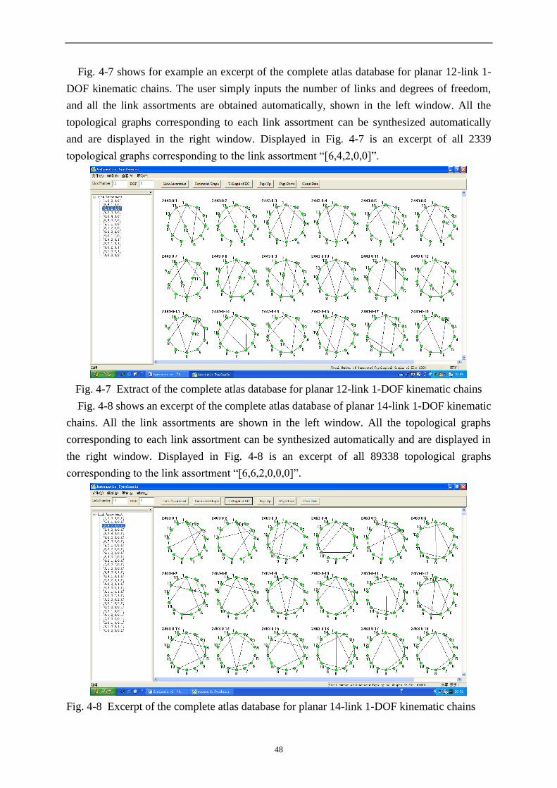
48
Fig. 4-7 shows for example an excerpt of the complete atlas database for planar 12-link 1-
DOF kinematic chains. The user simply inputs the number of links and degrees of freedom,
and all the link assortments are obtained automatically, shown in the left window. All the
topological graphs corresponding to each link assortment can be synthesized automatically
and are displayed in the right window. Displayed in Fig. 4-7 is an excerpt of all 2339
topological graphs corresponding to the link assortment “[6,4,2,0,0]”.
Fig. 4-7 Extract of the complete atlas database for planar 12-link 1-DOF kinematic chains
Fig. 4-8 shows an excerpt of the complete atlas database of planar 14-link 1-DOF kinematic
chains. All the link assortments are shown in the left window. All the topological graphs
corresponding to each link assortment can be synthesized automatically and are displayed in
the right window. Displayed in Fig. 4-8 is an excerpt of all 89338 topological graphs
corresponding to the link assortment “[6,6,2,0,0,0]”.
Fig. 4-8 Excerpt of the complete atlas database for planar 14-link 1-DOF kinematic chains
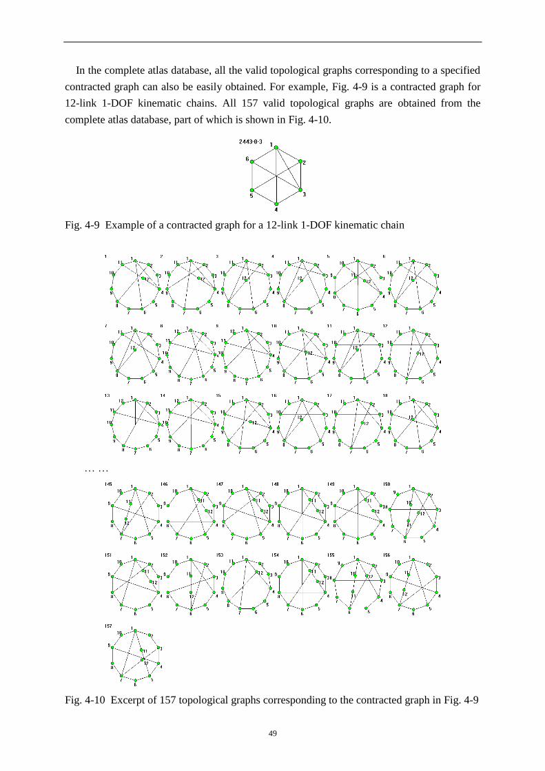
49
In the complete atlas database, all the valid topological graphs corresponding to a specified
contracted graph can also be easily obtained. For example, Fig. 4-9 is a contracted graph for
12-link 1-DOF kinematic chains. All 157 valid topological graphs are obtained from the
complete atlas database, part of which is shown in Fig. 4-10.
Fig. 4-9 Example of a contracted graph for a 12-link 1-DOF kinematic chain
… …
Fig. 4-10 Excerpt of 157 topological graphs corresponding to the contracted graph in Fig. 4-9

50
Fig. 4-11 is a contracted graph for 14-link 1-DOF kinematic chains. All 1930 valid
topological graphs can also be obtained from the atlas database, some of which are shown in
Fig. 4-12.
Fig. 4-11 Example of a contracted graph for a 14-link 1-DOF kinematic chains
… …
Fig. 4-12 Excerpt of the 1930 valid topological graphs for the contracted graph in Fig. 4-11
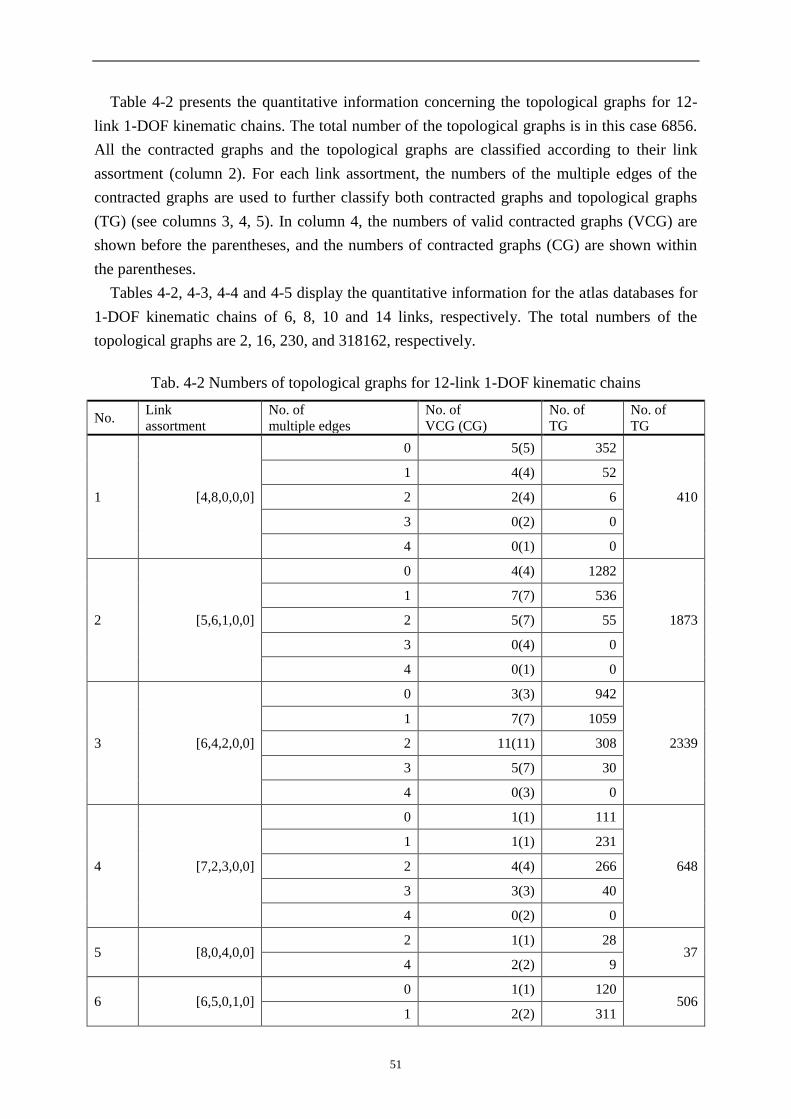
51
Table 4-2 presents the quantitative information concerning the topological graphs for 12-
link 1-DOF kinematic chains. The total number of the topological graphs is in this case 6856.
All the contracted graphs and the topological graphs are classified according to their link
assortment (column 2). For each link assortment, the numbers of the multiple edges of the
contracted graphs are used to further classify both contracted graphs and topological graphs
(TG) (see columns 3, 4, 5). In column 4, the numbers of valid contracted graphs (VCG) are
shown before the parentheses, and the numbers of contracted graphs (CG) are shown within
the parentheses.
Tables 4-2, 4-3, 4-4 and 4-5 display the quantitative information for the atlas databases for
1-DOF kinematic chains of 6, 8, 10 and 14 links, respectively. The total numbers of the
topological graphs are 2, 16, 230, and 318162, respectively.
Tab. 4-2 Numbers of topological graphs for 12-link 1-DOF kinematic chains
No. Link
assortment
No. of
multiple edges
No. of
VCG (CG)
No. of
TG
No. of
TG
1 [4,8,0,0,0]
0 5(5) 352
410
1 4(4) 52
2 2(4) 6
3 0(2) 0
4 0(1) 0
2 [5,6,1,0,0]
0 4(4) 1282
1873
1 7(7) 536
2 5(7) 55
3 0(4) 0
4 0(1) 0
3 [6,4,2,0,0]
0 3(3) 942
2339
1 7(7) 1059
2 11(11) 308
3 5(7) 30
4 0(3) 0
4 [7,2,3,0,0]
0 1(1) 111
648
1 1(1) 231
2 4(4) 266
3 3(3) 40
4 0(2) 0
5 [8,0,4,0,0] 2 1(1) 28
37 4 2(2) 9
6 [6,5,0,1,0] 0 1(1) 120
506 1 2(2) 311

52
2 2(2) 69
3 1(2) 6
7 [7,3,1,1,0]
1 2(2) 386
716 2 3(3) 243
3 5(5) 87
4 0(1) 0
8 [8,1,2,1,0]
2 1(1) 74
147 3 2(2) 65
4 1(1) 8
9 [8,2,0,2,0]
2 1(1) 32
63 3 1(1) 21
4 2(2) 10
10 [9,0,1,2,0] 4 1(1) 7 7
11 [7,4,0,0,1] 2 1(1) 40
49 3 1(1) 9
12 [8,2,1,0,1] 3 2(2) 46 46
13 [9,0,2,0,1] 4 1(1) 5 5
14 [9,1,0,1,1] 4 1(1) 8 8
15 [A,0,0,0,2] 1 1(1) 2 2
Tab. 4-3 Numbers of topological graphs for 6-link 1-DOF kinematic chains
No. Link
assortment
No. of
multiple-edges
No. of
VCG (CG)
No. of
TG
No. of
TG
1 [4,2] 2 1(1) 2 2
Tab. 4-4 Numbers of topological graphs for 8-link 1-DOF kinematic chains
No. Link
assortment
No. of
multiple-edges
No. of
VCG (CG)
No. of
TG
No. of
TG
1 [4,4,0] 0 1(1) 6
9 2 1(1) 3
2 [5,2,1] 2 1(1) 5 5
3 [6,0,2] 3 1(1) 2 2
Tab. 4-5 Numbers of topological graphs for 10-link 1-DOF kinematic chains
No. link
assortment
No. of
multiple-edges
No. of
VCG (CG)
No. of
TG
No. of
TG
1 [4,6,0,0]
0 2(2) 39
50 1 1(1) 8
2 1(1) 3
3 0(1) 0

53
2 [5,4,1,0]
0 1(1) 42
95 1 1(1) 43
2 1(1) 10
3 0 (1) 0
3 [6,2,2,0]
1 1(1) 32
57 2 1(1) 15
3 2(2) 10
4 [7,0,3,0] 3 1(1) 3 3
5 [6,3,0,1] 2 1(1) 15 15
6 [7,1,1,1] 3 1(1) 8 8
7 [8,0,0,2] 1 1(1) 2 2
Tab. 4-6 Numbers of topological graphs for 14-link 1-DOF kinematic chains
No. link
assortment
No. of
multiple-edges
No. of
VCG (CG)
No. of
TG
No. of
TG
1 [4,A,0,0,0,0]
0 18(18) 3994
4420
1 16(18) 410
2 5(17) 16
3 0(9) 0
4 0(3) 0
5 0(1) 0
2 [5,8,1,0,0,0]
0 25(25) 30510
38098
1 48(50) 7192
2 27 (51) 396
3 0(27) 0
4 0(8) 0
5 0(1) 0
3 [6,6,2,0,0,0]
0 27(27) 55825
89338
1 68(68) 29270
2 80(91) 4103
3 21(60) 140
4 0(21) 0
5 0(3) 0
4 [7,4,3,0,0,0]
0 11(11) 25653
62854
1 31(31) 27516
2 53(54) 8915
3 35(47) 770
4 0(19) 0
5 0(3) 0
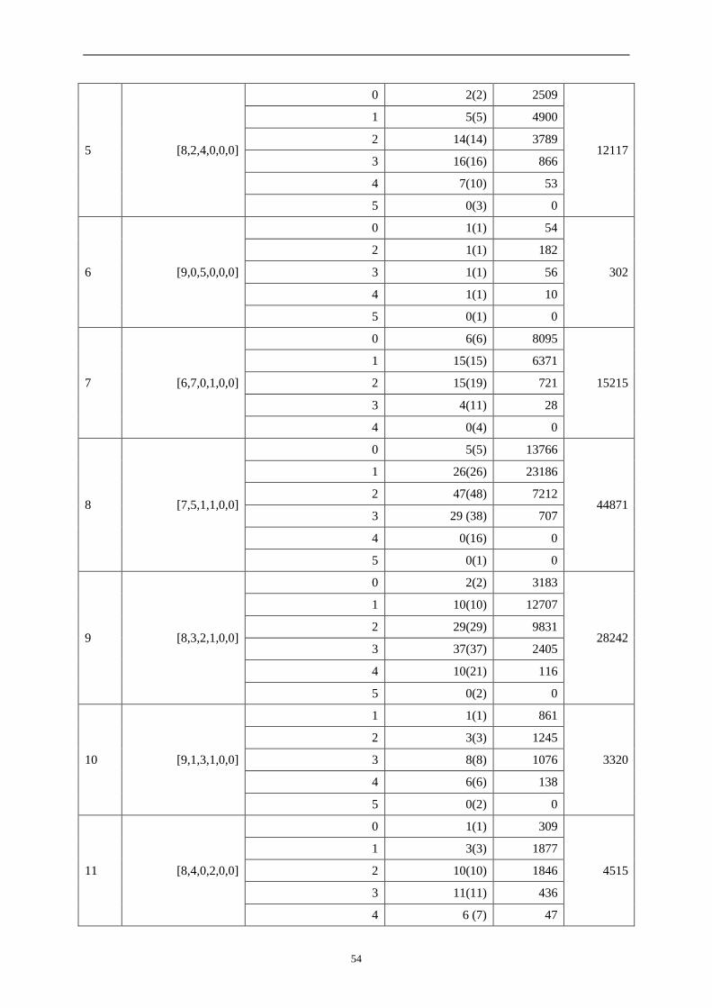
54
5 [8,2,4,0,0,0]
0 2(2) 2509
12117
1 5(5) 4900
2 14(14) 3789
3 16(16) 866
4 7(10) 53
5 0(3) 0
6 [9,0,5,0,0,0]
0 1(1) 54
302
2 1(1) 182
3 1(1) 56
4 1(1) 10
5 0(1) 0
7 [6,7,0,1,0,0]
0 6(6) 8095
15215
1 15(15) 6371
2 15(19) 721
3 4(11) 28
4 0(4) 0
8 [7,5,1,1,0,0]
0 5(5) 13766
44871
1 26(26) 23186
2 47(48) 7212
3 29 (38) 707
4 0(16) 0
5 0(1) 0
9 [8,3,2,1,0,0]
0 2(2) 3183
28242
1 10(10) 12707
2 29(29) 9831
3 37(37) 2405
4 10(21) 116
5 0(2) 0
10 [9,1,3,1,0,0]
1 1(1) 861
3320
2 3(3) 1245
3 8(8) 1076
4 6(6) 138
5 0(2) 0
11 [8,4,0,2,0,0]
0 1(1) 309
4515
1 3(3) 1877
2 10(10) 1846
3 11(11) 436
4 6 (7) 47

55
5 0 (2) 0
12 [9,2,1,2,0,0]
1 1(1) 422
3083
2 4(4) 1452
3 9(9) 1006
4 10(10) 203
5 0 (2) 0
13 [A,0,2,2,0,0]
3 2(2) 158
216 4 2(2) 36
5 3(3) 22
14 [A,1,0,3,0,0] 3 1(1) 37
77 4 1(1) 40
15 [7,6,0,0,1,0]
0 1(1) 342
2672
1 3(3) 1588
2 5(5) 692
3 3(5) 50
4 0(1) 0
16 [8,4,1,0,1,0]
1 3(3) 2017
5120 2 9(9) 2446
3 11(11) 625
4 3(6) 32
17 [9,2,2,0,1,0]
2 4(4) 1078
1858 3 6(6) 600
4 7(7) 180
5 0(1) 0
18 [A,0,3,0,1,0] 3 1(1) 39
79 4 1(1) 40
19 [9,3,0,1,1,0]
2 2(2) 437
857 3 4(4) 342
4 4(4) 78
5 0(1) 0
20 [A,1,1,1,1,0]
3 1(1) 139
306 4 4(4) 151
5 2(2) 16
21 [B,0,0,2,1,0] 5 1(1) 7 7
22 [A,2,0,0,2,0]
3 1(1) 32
63 4 1(1) 21
5 2(2) 10
23 [B,0,1,0,2,0] 5 1(1) 7 7

56
24 [8,5,0,0,0,1] 2 1(1) 120
180 3 1(1) 60
25 [9,3,1,0,0,1] 3 3(3) 211
232 4 1(1) 21
26 [A,1,2,0,0,1] 4 2(2) 49 49
27 [A,2,0,1,0,1] 4 2(2) 46 46
28 [B,0,1,1,0,1] 5 1(1) 8 8
29 [B,1,0,0,1,1] 5 1(1) 8 8
30 [C,0,0,0,0,2] 1 1(1) 2 2
Mechanisms can further be synthesized from the atlas database of kinematic chains. For
example, the total numbers of 1-DOF non-fractionated mechanisms are: 5 mechanisms for 6-
link kinematic chains, 71 mechanisms for 8-link kinematic chains, 1834 mechanisms for 10-
link kinematic chains, 75397 mechanisms for 12-link kinematic chains, and 4274510
mechanisms for 14-link kinematic chains. Table 4-7 displays the quantitative information for
the atlas databases of non-fractionated kinematic chains and mechanisms with up to 19 links.
Tab. 4-7 Numbers of non-fractionated kinematic chains and mechanisms
N F No. of
LAs
No. of
VCGs
No. of
KCs
Comfirms with
others
No. of
Mechanisms
Comfirms with
others
6 1 1 1 2 Acknowledged 5 Acknowledged
7 2 1 1 3 Acknowledged 11 Acknowledged
8 1 3 4 16 Acknowledged 71 Acknowledged
3 1 1 5 Acknowledged 18 Acknowledged
9 2 3 4 35 Acknowledged 220 Refs.[15],[125]
4 1 1 6 Acknowledged 28 Ref.[125]
10
1 7 15 230 Refs.[15],[125] 1834 Refs.[15],[125]
3 3 4 74 Acknowledged 517 Refs.[15],[125]
5 1 1 8 Acknowledged 39 Ref.[125]
11
2 7 16 753 Refs.[15],[125] 7156 Refs.[15],[125]
4 3 4 126 Ref.[125] 1056 Ref.[125]
6 1 1 10 Acknowledged 55 Ref.[125]
12
1 15 97 6856 Refs.[15],[125] 75397 Refs.[15],[125]
3 7 17 1962 Refs.[15],[125] 20737 Refs.[15],[125]
5 3 4 212 Ref.[125] 1955 Ref.[125]
7 1 1 12 New result 71 Refs.[15],[125]
13
2 15 109 27496 Refs.[15],[125] 335398 Refs.[15],[125]
4 7 17 4356 Ref.[125] 51245 Ref.[125]
6 3 4 325 Ref.[125] 3387 Ref.[125]

57
8 1 1 14 New result 93 New result
14
1 30 923 318162 Ref.[125] 4274510 New result
3 15 116 83547 Refs.[15],[125] 1105923 Refs.[15],[125]
5 7 17 8846 Ref.[125] 113387 Ref.[125]
7 3 4 490 New result 5550 New result
9 1 1 17 New result 116 New result
15
2 30 1090 1432730 Ref.[125] 20737954 New result
4 15 117 216291 Ref.[125] 3093027 New result
6 7 17 16649 Ref.[125] 231664 Ref.[125]
8 3 4 699 New result 8727 New result
10 1 1 19 New result 145 New result
16
1 58 12612 19668033 New result
3 30 1169 4805764 Ref.[125] 74393277 New result
5 15 118 504599 New result 7732861 New result
7 7 17 29686 New result 444007 New result
9 3 4 989 New result 13234 New result
11 1 1 22 New result 175 New result
17
4 30 1188 13743920 Ref.[125] 226621724 New result
6 15 118 1086580 New result 17773527 New result
8 7 17 50484 New result 808720 New result
10 3 4 1343 New result 19493 New result
12 1 1 25 New result 213 New result
18
5 30 1196 35315327 New result 617745323 New result
7 15 118 2199179 New result 38208747 New result
9 7 17 82749 New result 1410661 New result
11 3 2 1811 New result 27975 New result
13 1 1 28 New result 251 New result
19
6 30 1197 83708033 New result
8 15 118 4226542 New result 77742656 New result
10 7 17 131160 New result 2372955 New result
12 3 2 2377 New result 39291 New result
14 1 1 31 New result 298 New result
From Tab. 4-7 we can see that although great advancements have been made since the
1960s, which is also shown in the two review papers on structural synthesis [15,125], a lot of
new results have been achieved with the new synthesis method, especially those kinematic
chains or mechanisms with more complex structures. As for existing synthesis results
reported in literature, the results here are the same as the widely acknowledged ones. There
are also a lot of new results never obtained before, in particular for complex kinematic chains
58
and mechanisms.
4.8 Summary
In this chapter, an effective, fully-automatic and designer-friendly method is proposed to
synthesize the whole family of planar non-fractionated kinematic chains and mechanisms with
specified number of links and degrees of freedom. The effectiveness of the method is proved
by successful synthesis of all the valid kinematic chains reported before. More importantly,
with this method a lot of new results have been obtained, many of which are complex
kinematic chains and mechanisms never synthesized otherwise before.
As so many topological structures of non-fractionated kinematic chains exist, for the sake
of practical application in the conceptual stage of mechanisms, the corresponding atlas
databases of non-fractionated kinematic chains and mechanisms are also established, which
contains all the valid non-fractionated topological graphs classified by their structural
characteristics.
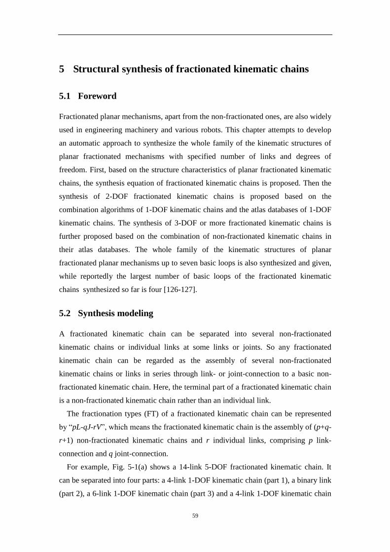
59
5 Structural synthesis of fractionated kinematic chains
5.1 Foreword
Fractionated planar mechanisms, apart from the non-fractionated ones, are also widely
used in engineering machinery and various robots. This chapter attempts to develop
an automatic approach to synthesize the whole family of the kinematic structures of
planar fractionated mechanisms with specified number of links and degrees of
freedom. First, based on the structure characteristics of planar fractionated kinematic
chains, the synthesis equation of fractionated kinematic chains is proposed. Then the
synthesis of 2-DOF fractionated kinematic chains is proposed based on the
combination algorithms of 1-DOF kinematic chains and the atlas databases of 1-DOF
kinematic chains. The synthesis of 3-DOF or more fractionated kinematic chains is
further proposed based on the combination of non-fractionated kinematic chains in
their atlas databases. The whole family of the kinematic structures of planar
fractionated planar mechanisms up to seven basic loops is also synthesized and given,
while reportedly the largest number of basic loops of the fractionated kinematic
chains synthesized so far is four [126-127].
5.2 Synthesis modeling
A fractionated kinematic chain can be separated into several non-fractionated
kinematic chains or individual links at some links or joints. So any fractionated
kinematic chain can be regarded as the assembly of several non-fractionated
kinematic chains or links in series through link- or joint-connection to a basic non-
fractionated kinematic chain. Here, the terminal part of a fractionated kinematic chain
is a non-fractionated kinematic chain rather than an individual link.
The fractionation types (FT) of a fractionated kinematic chain can be represented
by “pL-qJ-rV”, which means the fractionated kinematic chain is the assembly of (p+q-
r+1) non-fractionated kinematic chains and r individual links, comprising p link-
connection and q joint-connection.
For example, Fig. 5-1(a) shows a 14-link 5-DOF fractionated kinematic chain. It
can be separated into four parts: a 4-link 1-DOF kinematic chain (part 1), a binary link
(part 2), a 6-link 1-DOF kinematic chain (part 3) and a 4-link 1-DOF kinematic chain
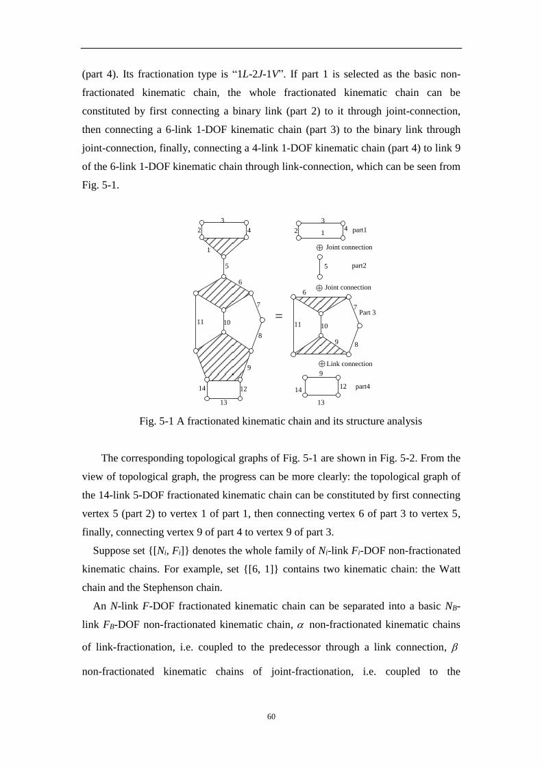
60
(part 4). Its fractionation type is “1L-2J-1V”. If part 1 is selected as the basic non-
fractionated kinematic chain, the whole fractionated kinematic chain can be
constituted by first connecting a binary link (part 2) to it through joint-connection,
then connecting a 6-link 1-DOF kinematic chain (part 3) to the binary link through
joint-connection, finally, connecting a 4-link 1-DOF kinematic chain (part 4) to link 9
of the 6-link 1-DOF kinematic chain through link-connection, which can be seen from
Fig. 5-1.
1
2
3
4
5
6
7
8
9
1011
41
5
6
7
89
1011
12
13
14 12
13
14
part1
part2
Part 3
part4
Joint connection
Joint connection
Link connection
2
3
=
9
Fig. 5-1 A fractionated kinematic chain and its structure analysis
The corresponding topological graphs of Fig. 5-1 are shown in Fig. 5-2. From the
view of topological graph, the progress can be more clearly: the topological graph of
the 14-link 5-DOF fractionated kinematic chain can be constituted by first connecting
vertex 5 (part 2) to vertex 1 of part 1, then connecting vertex 6 of part 3 to vertex 5,
finally, connecting vertex 9 of part 4 to vertex 9 of part 3.
Suppose set {[Ni, Fi]} denotes the whole family of Ni-link Fi-DOF non-fractionated
kinematic chains. For example, set {[6, 1]} contains two kinematic chain: the Watt
chain and the Stephenson chain.
An N-link F-DOF fractionated kinematic chain can be separated into a basic NB-
link FB-DOF non-fractionated kinematic chain, non-fractionated kinematic chains
of link-fractionation, i.e. coupled to the predecessor through a link connection,
non-fractionated kinematic chains of joint-fractionation, i.e. coupled to the

61
predecessor through a joint connection, and NV individual links. The number of links
and degrees of freedom of these kinematic chains satisfy
FNFFFFFFF
NNNNNNNNN
VJJJLLLB
VJJJLLLB
)()(
)()(
2121
2121
(5-1)
1
2
3
4
5
6
7
89
1011
12
13
14
2
3
4
7
1011
12
13
9
9
14
1
5
6
Edge connection
Vertex connection
= 8
Edge connection
Part 1
Part 2
Part 3
Part 4
Fig. 5-2 Topological graphs of Fig. 5-1
Where iN , iF (i = L1, L2, …, L ) are the number of links and degrees of freedom of
the non-fractionated kinematic chains, and jN , jF (j = J1, J2, …, J ) are the
number of links and degrees of freedom of the non-fractionated kinematic chains.
For the required N-link F-DOF fractionated kinematic chains, all possible
combinations of non-fractionated kinematic chains can be obtained from Eq. (5-1),
which becomes the synthesis constraint equation of fractionated kinematic chains.
5.3 Synthesis of 2-DOF fractionated kinematic chains
5.3.1 Rules of combination
According to the synthesis constraint equation of fractionated kinematic chains, the
determination of all combinations of 2-DOF fractionated kinematic chains becomes
simple. All 2-DOF fractionated kinematic chains can contain only one fractionated
link, i.e. all 2-DOF fractionated kinematic chains can be synthesized by the
combination of two appropriate 1-DOF kinematic chains.

62
In general, for the synthesis of N-link 2-DOF fractionated kinematic chains, the
number of links of appropriate 1-DOF kinematic chains satisfies
)2,1(,10,8,6,4
1
21
21
iN
NN
NNN
i
(5-2)
where N1 and N2 are the numbers of links of the appropriate 1-DOF kinematic chains.
Without loss of generality, we suppose N1N2.
For example, all 11-link 2-DOF fractionated kinematic chains can be synthesized
by combining
(1)a 4-link 1-DOF kinematic chain with 16 possible 8-link 1-DOF kinematic
chains;
(2) two possible 6-link 1-DOF kinematic chains.
In order to avoid isomorphism in the synthesis process, the vertices in each
topological graph of 1-DOF kinematic chains are classified into different sets based
on their topological symmetry. Two vertices are topologically symmetric if one can
switch the labels of the two vertices and find a relabeling of the remaining vertices
such that the resulting graph is the same as the original one, i.e. that they have the
same adjacency matrices. A set Si for which every pair of vertices in Si is
topologically symmetric is called a symmetry set. For a given topological graph, all
its symmetry sets Si (i=1, 2, … , r , where r is the number of sets) constitute the
vertex-symmetry set (VS) of the topological graph, i.e. VS ={S1, S2, …, Sr}. Each
symmetry set Si is an equivalent class that is uniquely determined by any
representative vertex in this set. A set of one representative vertex from each Si is
called a vertex-asymmetry set VA. Obviously, any two vertices in VA are asymmetric.
(a) (b)
Fig.5-3 Two 6-link 1-DOF kinematic chains
For the example of Fig.5-3(a), vertices 1 and 4 are symmetrical, and vertices 2, 3, 5
and 6 are also symmetrical. Thus, the vertex-symmetry set for the topological graph in
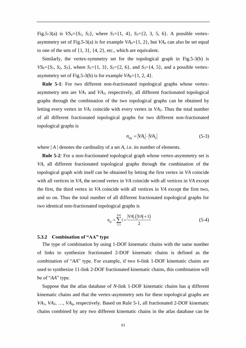
63
Fig.5-3(a) is VSa={S1, S2}, where S1={1, 4}, S2={2, 3, 5, 6}. A possible vertex-
asymmetry set of Fig.5-3(a) is for example VAa={1, 2}, but VAa can also be set equal
to one of the sets of {1, 3}, {4, 2}, etc., which are equivalent.
Similarly, the vertex-symmetry set for the topological graph in Fig.5-3(b) is
VSb={S1, S2, S3}, where S1={1, 3}, S2={2, 6}, and S3={4, 5}, and a possible vertex-
asymmetry set of Fig.5-3(b) is for example VAb={1, 2, 4}.
Rule 5-1: For two different non-fractionated topological graphs whose vertex-
asymmetry sets are VA1 and VA2, respectively, all different fractionated topological
graphs through the combination of the two topological graphs can be obtained by
letting every vertex in VA1 coincide with every vertex in VA2. Thus the total number
of all different fractionated topological graphs for two different non-fractionated
topological graphs is
21 VAVAndg (5-3)
where | A | denotes the cardinality of a set A, i.e. its number of elements.
Rule 5-2: For a non-fractionated topological graph whose vertex-asymmetry set is
VA, all different fractionated topological graphs through the combination of the
topological graph with itself can be obtained by letting the first vertex in VA coincide
with all vertices in VA, the second vertex in VA coincide with all vertices in VA except
the first, the third vertex in VA coincide with all vertices in VA except the first two,
and so on. Thus the total number of all different fractionated topological graphs for
two identical non-fractionated topological graphs is
1
. 1
2
VA
ig
i
VA VAn i
(5-4)
5.3.2 Combination of “AA” type
The type of combination by using 1-DOF kinematic chains with the same number
of links to synthesize fractionated 2-DOF kinematic chains is defined as the
combination of “AA” type. For example, if two 6-link 1-DOF kinematic chains are
used to synthesize 11-link 2-DOF fractionated kinematic chains, this combination will
be of “AA” type.
Suppose that the atlas database of N-link 1-DOF kinematic chains has q different
kinematic chains and that the vertex-asymmetry sets for these topological graphs are
VA1, VA2, …, VAq, respectively. Based on Rule 5-1, all fractionated 2-DOF kinematic
chains combined by any two different kinematic chains in the atlas database can be
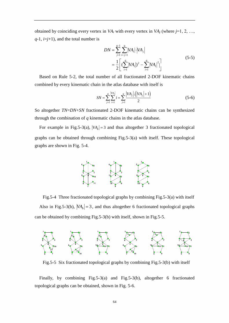
64
obtained by coinciding every vertex in VAi with every vertex in VAj (where j=1, 2, …,
q-1, i=j+1), and the total number is
q
i
i
q
i
i
q
j
j
q
ji
i
VAVA
VAVADN
1
22
1
1
1 1
)(2
1 (5-5)
Based on Rule 5-2, the total number of all fractionated 2-DOF kinematic chains
combined by every kinematic chain in the atlas database with itself is
1 1 1
. 1
2
jVAq qj j
j i j
VA VASN i
(5-6)
So altogether TN=DN+SN fractionated 2-DOF kinematic chains can be synthesized
through the combination of q kinematic chains in the atlas database.
For example in Fig.5-3(a), 3aVA and thus altogether 3 fractionated topological
graphs can be obtained through combining Fig.5-3(a) with itself. These topological
graphs are shown in Fig. 5-4.
Fig.5-4 Three fractionated topological graphs by combining Fig.5-3(a) with itself
Also in Fig.5-3(b), 3bVA , and thus altogether 6 fractionated topological graphs
can be obtained by combining Fig.5-3(b) with itself, shown in Fig.5-5.
Fig.5-5 Six fractionated topological graphs by combining Fig.5-3(b) with itself
Finally, by combining Fig.5-3(a) and Fig.5-3(b), altogether 6 fractionated
topological graphs can be obtained, shown in Fig. 5-6.
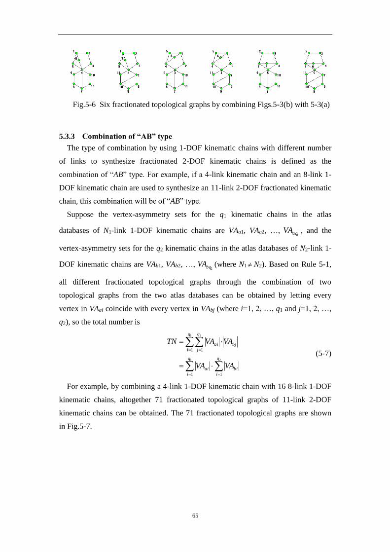
65
Fig.5-6 Six fractionated topological graphs by combining Figs.5-3(b) with 5-3(a)
5.3.3 Combination of “AB” type
The type of combination by using 1-DOF kinematic chains with different number
of links to synthesize fractionated 2-DOF kinematic chains is defined as the
combination of “AB” type. For example, if a 4-link kinematic chain and an 8-link 1-
DOF kinematic chain are used to synthesize an 11-link 2-DOF fractionated kinematic
chain, this combination will be of “AB” type.
Suppose the vertex-asymmetry sets for the q1 kinematic chains in the atlas
databases of N1-link 1-DOF kinematic chains are VAa1, VAa2, …, 1aqVA , and the
vertex-asymmetry sets for the q2 kinematic chains in the atlas databases of N2-link 1-
DOF kinematic chains are VAb1, VAb2, …, 2bqVA (where N1 N2). Based on Rule 5-1,
all different fractionated topological graphs through the combination of two
topological graphs from the two atlas databases can be obtained by letting every
vertex in VAai coincide with every vertex in VAbj (where i=1, 2, …, q1 and j=1, 2, …,
q2), so the total number is
21
1 2
11
1 1
q
i
bi
q
i
ai
bj
q
i
q
j
ai
VAVA
VAVATN
(5-7)
For example, by combining a 4-link 1-DOF kinematic chain with 16 8-link 1-DOF
kinematic chains, altogether 71 fractionated topological graphs of 11-link 2-DOF
kinematic chains can be obtained. The 71 fractionated topological graphs are shown
in Fig.5-7.

66

67
Fig.5-7 71 fractionated topological graphs through combination of 4-link and 8-
link 1-DOF kinematic chains
5.3.4 Synthesis results of 2-DOF fractionated kinematic chains
In this way, the whole atlas database of fractionated 2-DOF kinematic chains can be
established. Tab.5-1 shows the quantitative information concerning the whole family
of fractionated 2-DOF kinematic chains up to seven basic loops (column 1) and 17

68
links (column 2). The fractionation types (FT) are shown in column 3: “L” denotes
one fractionated link. Suppose operation “*” of two kinematic chain sets denotes the
connection of all possible pairs of elements from the two sets by one fractionated link.
For each fractionation type, the possible combinations of non-fractionated kinematic
chains (non-FKCs) and the synthesized fractionated kinematic chains (FKCs) are
shown in columns 4 and 5, respectively. For example, altogether 86 fractionated 11-
link 2-DOF are synthesized, which consist of two parts: (1) 71 fractionated
topological graphs are synthesized through the combination of 4-link kinematic chain
with 8-link 1-DOF kinematic chains; (2) 15 fractionated topological graphs are
synthesized through the combination of two 6-link 1-DOF kinematic chains.
The total number of 86 planar 11-link 2-DOF fractionated kinematic chains is
confirmed by Mruthyunjaya [15] and Martins [127]. The complete sets of planar 2-
DOF fractionated kinematic chains of 13, 15 and 17 links are obtained for the first
time and the corresponding topological graphs and their numbers are also totally new.
Tab. 5-1 Numbers of 2-DOF fractionated kinematic chains and their classification
V N FT Combination of
kinematic chains
No. of
FKCs
Total
Number
Compared with
other results
2 7 L {[4,1]}*{[4,1]} 1 1 Acknowledged
3 9 L {[4,1]}*{[6,1]} 5 5 Acknowledged
4 11 L {[4,1]}*{[8,1]} 71
86 Confirmed by [15,127] L {[6,1]}*{[6,1]} 15
5 13 L {[4,1]}*{[10,1]} 1834
2189 New result L {[6,1]}*{[8,1]} 355
6 15
L {[4,1]}*{[12,1]} 75397
87123 New result L {[6,1]}*{[10,1]} 9170
L {[8,1]}*{[8,1]} 2556
7 17
L {[4,1]}*{[14,1]} 4274510
4781709 New result L {[6,1]}*{[12,1]} 376985
L {[8,1]}*{[10,1]} 130214
5.4 Combination of three non-fractionated kinematic chains
Three non-fractionated kinematic chains used to form a fractionated chain must fit
in with one of the three cases: (1) three identical kinematic chains, (2) two identical
kinematic chains and another different one, (3) three different kinematic chains.

69
5.4.1 Combination rules for three identical kinematic chains
For a non-fractionated topological graph, assume its vertex-symmetry set is VS
={S1, S2, …, Sr}, and its vertex-asymmetry set is VA={*
1V , *
2V , …, *
rV }.
Case I Multiple fractionated link
Rule 5-3: All different fractionated topological graphs with multiple fractionated
vertex through the combination of three identical non-fractionated topological graphs
can be obtained by letting three vertices*
iV ,*
jV and*
kV coincide according
to rkji 1 . The total number can be given by
1
1 1 1
( 1)
2
VA VAj
mv
j i j
j jn i
(5-8)
For example, four different fractionated topological graphs can be obtained by
combining three identical topological graphs of Fig.5-3(a), shown in Fig. 5-8.
Fig. 5-8 Four fractionated topological graphs with multiple fractionated vertices
CaseⅡ Two different fractionated vertices
In a topological graph, let any two vertices constitute a vertex pair, denoted as (Vi,
Vj). An asymmetrical pair is constituted by two asymmetrical vertices. Two
asymmetrical pairs are said to be equivalent pairs if they are topologically
symmetrical. For example, the two asymmetrical pair (1,2) and (1,6) in Fig.5-3(a) are
equivalent pairs. For a topological graph, a set constituted by all possible
asymmetrical pairs without any equivalent pair is defined as the set of asymmetrical
vertex pairs (AP) of the graph. It follows that no equivalent pairs exist in AP. For
example, the set of asymmetrical vertex pairs for the topological graph in Fig.5-3(a) is
AP={(1,2),(1,3)}.

70
Rule 5-4: For a non-fractionated topological graph whose set of asymmetrical
vertex pairs is AP, the total number of fractionated topological graphs obtained by
letting two vertices of two non-fractionated graphs coincide with two asymmetrical
vertices of the third graph is
2VAAPnap (5-9)
For example, eight different fractionated topological graphs can be obtained by
combining three identical topological graphs of Fig.5-3(a) in this way, shown in
Fig.5-9.
Fig.5-9 Eight fractionated topological graphs of two fractionated vertices
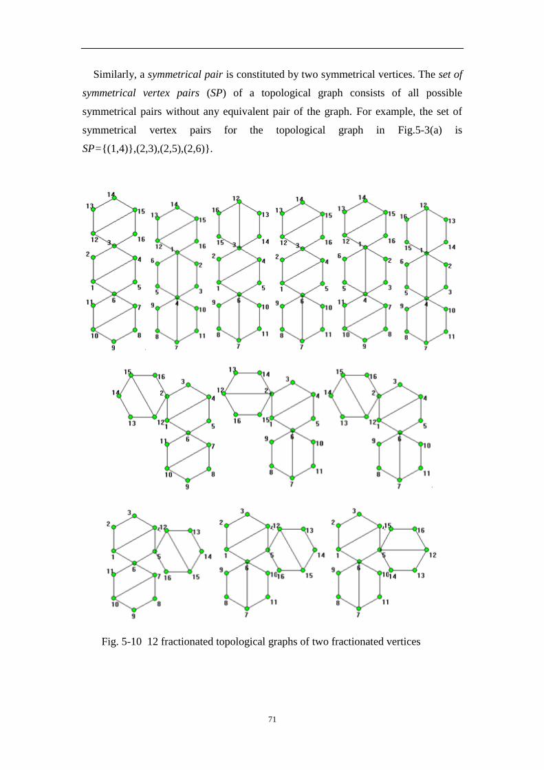
71
Similarly, a symmetrical pair is constituted by two symmetrical vertices. The set of
symmetrical vertex pairs (SP) of a topological graph consists of all possible
symmetrical pairs without any equivalent pair of the graph. For example, the set of
symmetrical vertex pairs for the topological graph in Fig.5-3(a) is
SP={(1,4)},(2,3),(2,5),(2,6)}.
Fig. 5-10 12 fractionated topological graphs of two fractionated vertices
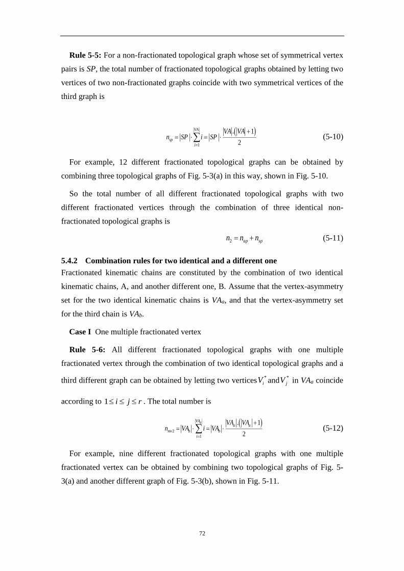
72
Rule 5-5: For a non-fractionated topological graph whose set of symmetrical vertex
pairs is SP, the total number of fractionated topological graphs obtained by letting two
vertices of two non-fractionated graphs coincide with two symmetrical vertices of the
third graph is
1
. 1
2
VA
sp
i
VA VAn SP i SP
(5-10)
For example, 12 different fractionated topological graphs can be obtained by
combining three topological graphs of Fig. 5-3(a) in this way, shown in Fig. 5-10.
So the total number of all different fractionated topological graphs with two
different fractionated vertices through the combination of three identical non-
fractionated topological graphs is
spap nnn 2 (5-11)
5.4.2 Combination rules for two identical and a different one
Fractionated kinematic chains are constituted by the combination of two identical
kinematic chains, A, and another different one, B. Assume that the vertex-asymmetry
set for the two identical kinematic chains is VAa, and that the vertex-asymmetry set
for the third chain is VAb.
Case I One multiple fractionated vertex
Rule 5-6: All different fractionated topological graphs with one multiple
fractionated vertex through the combination of two identical topological graphs and a
third different graph can be obtained by letting two vertices*
iV and*
jV in VAa coincide
according to rji 1 . The total number is
2
1
. 1
2
aVAa a
mv b b
i
VA VAn VA i VA
(5-12)
For example, nine different fractionated topological graphs with one multiple
fractionated vertex can be obtained by combining two topological graphs of Fig. 5-
3(a) and another different graph of Fig. 5-3(b), shown in Fig. 5-11.
73
Fig. 5-11 Nine fractionated topological graphs with two fractionated vertices
Case II Two different fractionated vertices
Rule 5-7: Assume the sets of asymmetrical vertex pairs and symmetrical vertex
pairs of kinematic chain A are APa and SPa, respectively. The total number of
different fractionated topological graphs obtained by combining the two identical
kinematic chains A first and then with kinematic chain B is
baabaa VAVAAPVAVASPW 24 (5-13)
For example, 48 different fractionated topological graphs can be obtained by
combining the kinematic chain A in Fig. 5-3(a) with itself first and then with
kinematic chain B in Fig. 5-3(b), shown in Fig. 5-12.

74
Fig. 5-12 Excerpt of 48 fractionated topological graphs of two fractionated
vertices
Rule 8: Assume the sets of asymmetrical vertex pairs and symmetrical vertex pairs
of kinematic chain B are APb and SPb, respectively. The total number of different
fractionated topological graphs obtained by letting two vertices of the two identical
graphs A coincide with two different vertices of graph B is

75
2
1
5 ab
VA
i
b VAAPiSPWa
(5-14)
For example, 25 different fractionated topological graphs can be obtained by
letting two vertices of the two identical graphs in Fig. 5-3(a) coincide with two
different vertices of graph B in Fig. 5-3(b), shown in Fig. 5-13.
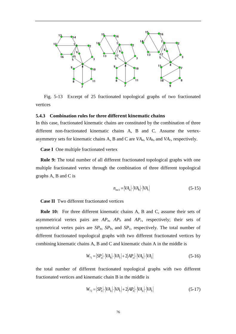
76
Fig. 5-13 Excerpt of 25 fractionated topological graphs of two fractionated
vertices
5.4.3 Combination rules for three different kinematic chains
In this case, fractionated kinematic chains are constituted by the combination of three
different non-fractionated kinematic chains A, B and C. Assume the vertex-
asymmetry sets for kinematic chains A, B and C are VAa, VAb, and VAc, respectively.
Case I One multiple fractionated vertex
Rule 9: The total number of all different fractionated topological graphs with one
multiple fractionated vertex through the combination of three different topological
graphs A, B and C is
cbamv VAVAVAn 3 (5-15)
Case II Two different fractionated vertices
Rule 10: For three different kinematic chains A, B and C, assume their sets of
asymmetrical vertex pairs are APa, APb and APc, respectively; their sets of
symmetrical vertex pairs are SPa, SPb, and SPc, respectively. The total number of
different fractionated topological graphs with two different fractionated vertices by
combining kinematic chains A, B and C and kinematic chain A in the middle is
cbacba VAVAAPVAVASPW 271 (5-16)
the total number of different fractionated topological graphs with two different
fractionated vertices and kinematic chain B in the middle is
cabcab VAVAAPVAVASPW 272 (5-17)
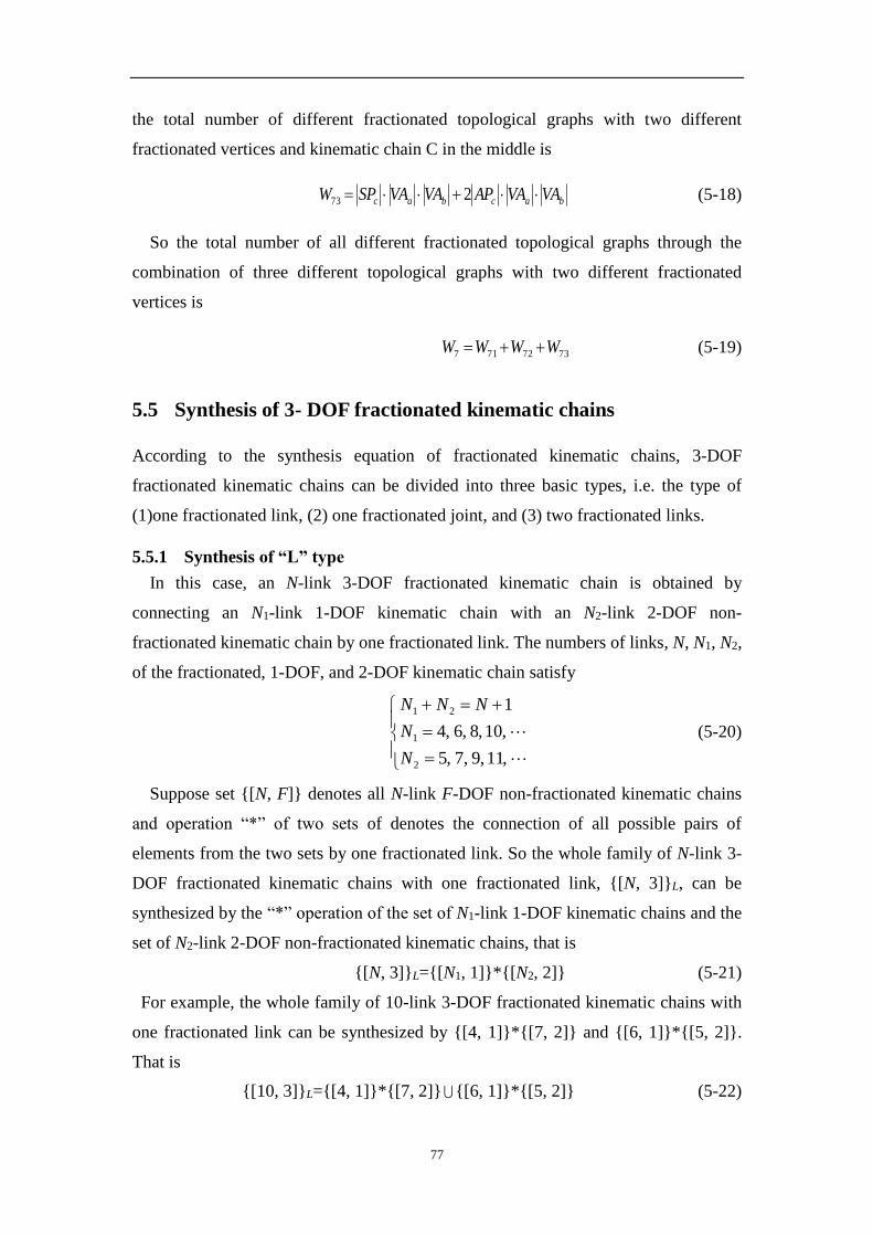
77
the total number of different fractionated topological graphs with two different
fractionated vertices and kinematic chain C in the middle is
bacbac VAVAAPVAVASPW 273 (5-18)
So the total number of all different fractionated topological graphs through the
combination of three different topological graphs with two different fractionated
vertices is
7372717 WWWW (5-19)
5.5 Synthesis of 3- DOF fractionated kinematic chains
According to the synthesis equation of fractionated kinematic chains, 3-DOF
fractionated kinematic chains can be divided into three basic types, i.e. the type of
(1)one fractionated link, (2) one fractionated joint, and (3) two fractionated links.
5.5.1 Synthesis of “L” type
In this case, an N-link 3-DOF fractionated kinematic chain is obtained by
connecting an N1-link 1-DOF kinematic chain with an N2-link 2-DOF non-
fractionated kinematic chain by one fractionated link. The numbers of links, N, N1, N2,
of the fractionated, 1-DOF, and 2-DOF kinematic chain satisfy
,11,9,7,5
,10,8,6,4
1
2
1
21
N
N
NNN
(5-20)
Suppose set {[N, F]} denotes all N-link F-DOF non-fractionated kinematic chains
and operation “*” of two sets of denotes the connection of all possible pairs of
elements from the two sets by one fractionated link. So the whole family of N-link 3-
DOF fractionated kinematic chains with one fractionated link, {[N, 3]}L, can be
synthesized by the “*” operation of the set of N1-link 1-DOF kinematic chains and the
set of N2-link 2-DOF non-fractionated kinematic chains, that is
{[N, 3]}L={[N1, 1]}*{[N2, 2]} (5-21)
For example, the whole family of 10-link 3-DOF fractionated kinematic chains with
one fractionated link can be synthesized by {[4, 1]}*{[7, 2]} and {[6, 1]}*{[5, 2]}.
That is
{[10, 3]}L={[4, 1]}*{[7, 2]} {[6, 1]}*{[5, 2]} (5-22)
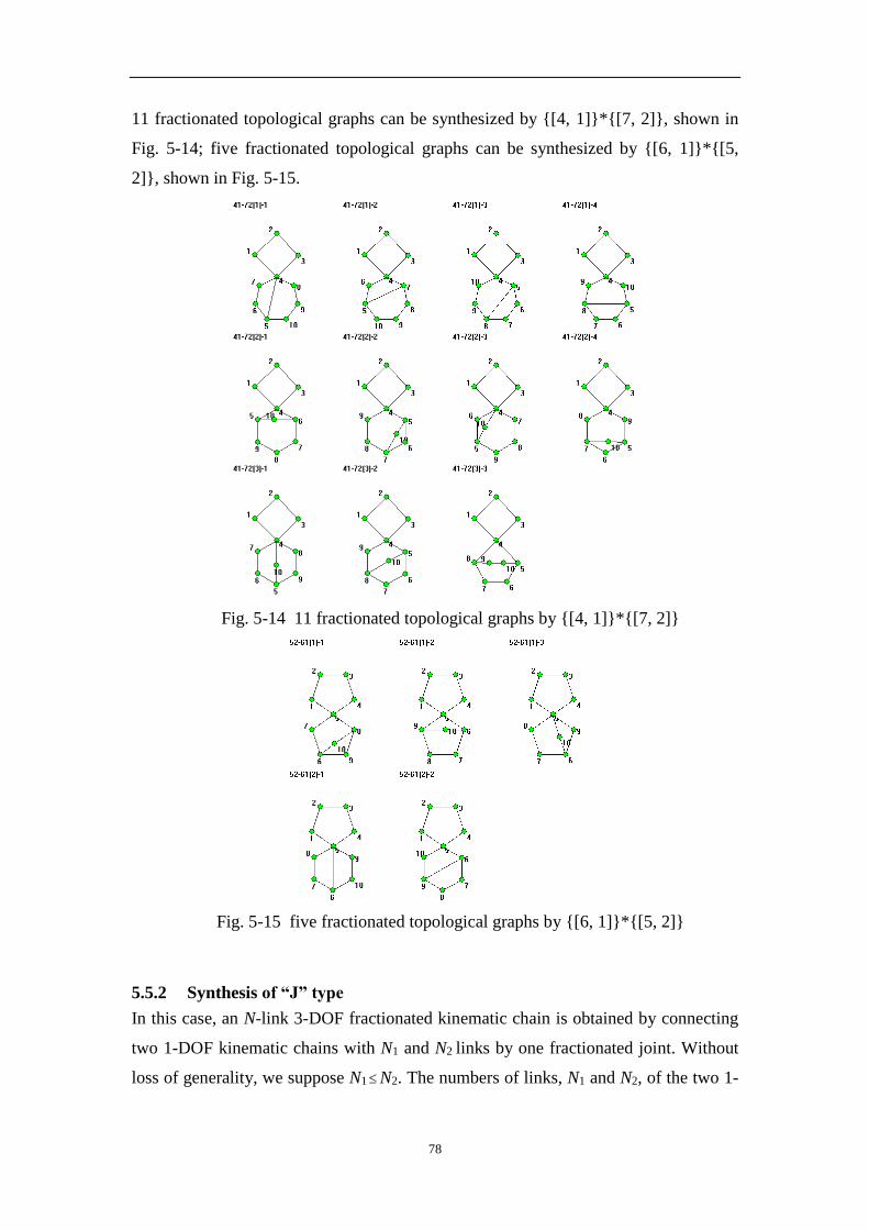
78
11 fractionated topological graphs can be synthesized by {[4, 1]}*{[7, 2]}, shown in
Fig. 5-14; five fractionated topological graphs can be synthesized by {[6, 1]}*{[5,
2]}, shown in Fig. 5-15.
Fig. 5-14 11 fractionated topological graphs by {[4, 1]}*{[7, 2]}
Fig. 5-15 five fractionated topological graphs by {[6, 1]}*{[5, 2]}
5.5.2 Synthesis of “J” type
In this case, an N-link 3-DOF fractionated kinematic chain is obtained by connecting
two 1-DOF kinematic chains with N1 and N2 links by one fractionated joint. Without
loss of generality, we suppose N1 N2. The numbers of links, N1 and N2, of the two 1-
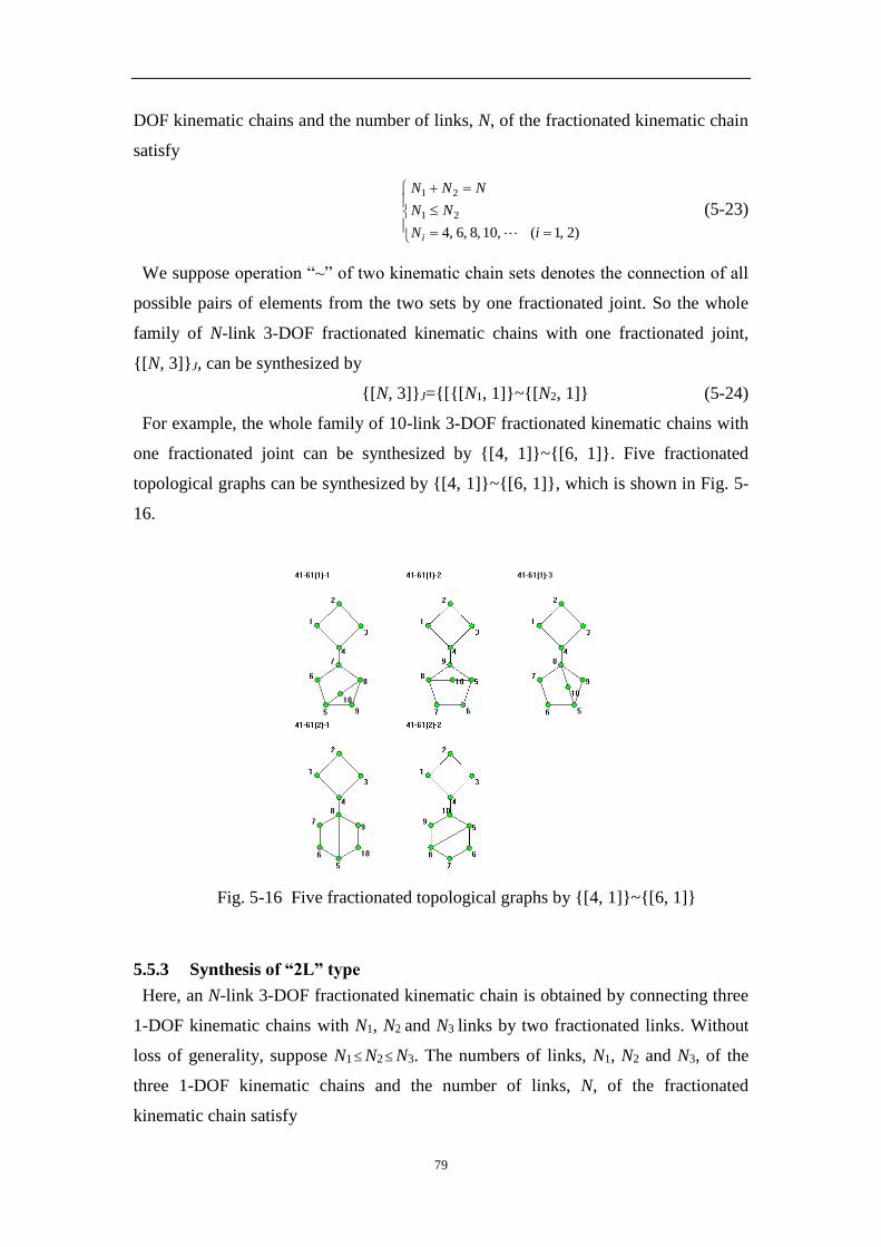
79
DOF kinematic chains and the number of links, N, of the fractionated kinematic chain
satisfy
)2,1(,10,8,6,4
21
21
iN
NN
NNN
i
(5-23)
We suppose operation “~” of two kinematic chain sets denotes the connection of all
possible pairs of elements from the two sets by one fractionated joint. So the whole
family of N-link 3-DOF fractionated kinematic chains with one fractionated joint,
{[N, 3]}J, can be synthesized by
{[N, 3]}J={[{[N1, 1]}~{[N2, 1]} (5-24)
For example, the whole family of 10-link 3-DOF fractionated kinematic chains with
one fractionated joint can be synthesized by {[4, 1]}~{[6, 1]}. Five fractionated
topological graphs can be synthesized by {[4, 1]}~{[6, 1]}, which is shown in Fig. 5-
16.
Fig. 5-16 Five fractionated topological graphs by {[4, 1]}~{[6, 1]}
5.5.3 Synthesis of “2L” type
Here, an N-link 3-DOF fractionated kinematic chain is obtained by connecting three
1-DOF kinematic chains with N1, N2 and N3 links by two fractionated links. Without
loss of generality, suppose N1 N2 N3. The numbers of links, N1, N2 and N3, of the
three 1-DOF kinematic chains and the number of links, N, of the fractionated
kinematic chain satisfy

80
)3,2,1(,10,8,6,4
2
321
221
iN
NNN
NNNN
i
(5-25)
We suppose operation “&(S1, S2, S3) ”denotes the connection of three elements from
the three sets in all possible ways by two fractionated links. So the whole family of N-
link 3-DOF fractionated kinematic chains with two fractionated links, {[N, 3]}TL, can
be synthesized by
{[N, 3]}2L=&({[N1, 1]}, {[N2, 1]}, {[N2, 1]}) (5-26)
For example, the whole family of 10-link 3-DOF fractionated kinematic chains with
two fractionated links can be synthesized by &({[4, 1]}, {[4, 1]}, {[4, 1]}). Three
fractionated topological graphs can be synthesized by the connection of the three 4-
link kinematic chains, shown in Fig. 5-17.
Fig. 5-17 Three fractionated topological graphs by &({[4, 1]}, {[4, 1]}, {[4, 1]})
5.5.4 Synthesis results of 3-DOF fractionated kinematic chains
Table 5-2 presents the quantitative information concerning the whole family of
fractionated 3-DOF kinematic chains up to seven basic loops (column 1) and 18 links
(column 2). The fractionation types (FT) are shown in column 3: “L” denotes one
fractionated link, “J” denotes one fractionated joint, and “2L” denotes two
fractionated links. For each fractionation type, the possible combinations of non-
fractionated kinematic chains (non-FKCs) and the synthesized fractionated kinematic
chains (FKCs) are shown in columns 4 and 5, respectively. The total number of 460
planar 12-link 3-DOF fractionated kinematic chains is confirmed by Mruthyunjaya
[15] and Martins [127]. The complete sets of planar 3-DOF fractionated kinematic
chains of 14, 16 and 18 links are obtained for the first time and the corresponding
topological graphs and their numbers are totally new.
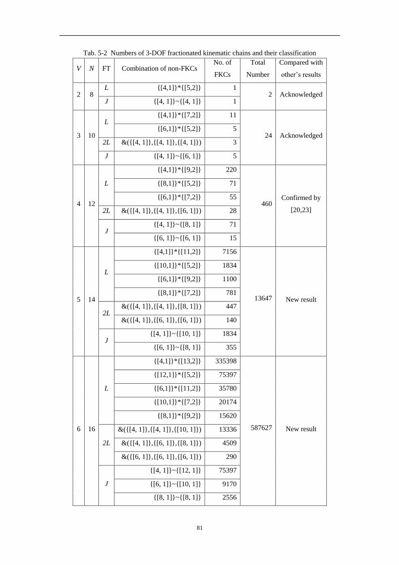
81
Tab. 5-2 Numbers of 3-DOF fractionated kinematic chains and their classification
V N FT Combination of non-FKCs No. of
FKCs
Total
Number
Compared with
other’s results
2 8 L {[4,1]}*{[5,2]} 1
2 Acknowledged J {[4, 1]}~{[4, 1]} 1
3 10
L {[4,1]}*{[7,2]} 11
24 Acknowledged {[6,1]}*{[5,2]} 5
2L &({[4, 1]},{[4, 1]},{[4, 1]}) 3
J {[4, 1]}~{[6, 1]} 5
4 12
L
{[4,1]}*{[9,2]} 220
460 Confirmed by
[20,23]
{[8,1]}*{[5,2]} 71
{[6,1]}*{[7,2]} 55
2L &({[4, 1]},{[4, 1]},{[6, 1]}) 28
J {[4, 1]}~{[8, 1]} 71
{[6, 1]}~{[6, 1]} 15
5 14
L
{[4,1]}*{[11,2]} 7156
13647 New result
{[10,1]}*{[5,2]} 1834
{[6,1]}*{[9,2]} 1100
{[8,1]}*{[7,2]} 781
2L &({[4, 1]},{[4, 1]},{[8, 1]}) 447
&({[4, 1]},{[6, 1]},{[6, 1]}) 140
J {[4, 1]}~{[10, 1]} 1834
{[6, 1]}~{[8, 1]} 355
6 16
L
{[4,1]}*{[13,2]} 335398
587627 New result
{[12,1]}*{[5,2]} 75397
{[6,1]}*{[11,2]} 35780
{[10,1]}*{[7,2]} 20174
{[8,1]}*{[9,2]} 15620
2L
&({[4, 1]},{[4, 1]},{[10, 1]}) 13336
&({[4, 1]},{[6, 1]},{[8, 1]}) 4509
&({[6, 1]},{[6, 1]},{[6, 1]}) 290
J
{[4, 1]}~{[12, 1]} 75397
{[6, 1]}~{[10, 1]} 9170
{[8, 1]}~{[8, 1]} 2556

82
7 18
L
{[4,1]}*{[15,2]} 20737954
34027016 New result
{[14,1]}*{[5,2]} 4274510
{[6,1]}*{[13,2]} 1676990
{[12,1]}*{[7,2]} 829367
{[10,1]}*{[9,2]} 403480
{[8,1]}*{[11,2]} 508076
2L
&({[4, 1]},{[4, 1]},{[12, 1]}) 625887
&({[4, 1]},{[6, 1]},{[10, 1]}) 138456
&({[4, 1]},{[8, 1]},{[8, 1]}) 37417
&({[6, 1]},{[6, 1]},{[8, 1]}) 13170
J
{[4, 1]}~{[14, 1]} 4274510
{[6, 1]}~{[12, 1]} 376985
{[8, 1]}~{[10, 1]} 130214
5.6 Synthesis of 4- DOF fractionated kinematic chains
According to the synthesis equation of fractionated kinematic chains, 4-DOF
fractionated kinematic chains can be divided into six basic types, i.e. the type of (1)
“L”, (2) “2L”, (3) “3L”, (4) “J”, (5) “L-J”, (6) “J-V”.
5.6.1 Synthesis of “L” type
In this case, the synthesis equation of N-link 4-DOF fractionated kinematic chains is
4
1
21
21
FF
NNN (5-27)
Obviously, an N-link 4-DOF fractionated kinematic chain can be obtained by
connecting a 1-DOF kinematic chain with a 3-DOF non-fractionated kinematic chain
or two 2-DOF kinematic chains.
(1) If an N-link 4-DOF fractionated kinematic chain is obtained by the combination
of an N1-link 1-DOF kinematic chain with an N2-link 3-DOF non-fractionated
kinematic chain through one fractionated link, the synthesis equation is
,,,,N
,,,,N
NNN
121086
10864
1
2
1
21
(5-28)
In this case, {[N, 4]}L={[N3, 1]}*{[N4, 3]}.

83
(2) If an N-link 4-DOF fractionated kinematic chain is obtained by the combination
of two 2-DOF kinematic chains through one fractionated link, the synthesis equation
is
),i(,,,,N
NN
NNN
i 2111975
1
43
43
(5-29)
where N3 and N4 are the numbers of links of the two 2-DOF kinematic chains.
Without loss of generality, suppose N3N4. In this case, {[N, 4]}L=N1, 2]}*{[N2, 2]}.
For example, the whole family of 11-link 4-DOF fractionated kinematic chains
with one fractionated link can be synthesized by {[4, 1]}*{[8, 3]}, {[6, 1]}*{[6, 3]}
and {[5, 2]}*{[7, 2]}. That is
{[11, 4]}L={[4, 1]}*{[8, 3]} {[6, 1]}*{[6, 3]} {[5, 2]}*{[7, 2]} (5-30)
11 fractionated topological graphs can be synthesized by {[5, 2]}*{[7, 2]}, shown in
Fig. 5-18. Moreover, 18 fractionated topological graphs can be synthesized by {[4,
1]}*{[8, 3]}, and five fractionated topological graphs can be synthesized by {[6,
1]}*{[6, 3]}.
Fig. 5-18 11 fractionated topological graphs by {[5, 2]}*{[7, 2]}
5.6.2 Synthesis of “2L” type
In this case, the synthesis equation of N-link 4-DOF fractionated kinematic chains is

84
,11975N
2110864
2
3
21
321
,,,
),i(,,,,N
NN
NNNN
i (5-31)
Obviously, an N-link 4-DOF fractionated kinematic chain can be obtained by
connecting two 1-DOF kinematic chains (with N1 and N2 links and suppose N1N2)
and a 2-DOF kinematic chain (with N3 links). That is
{[N, 4]}2L=&({[N1, 1]}, {[N2, 1]}, {[N3, 2]}) (5-32)
For example, the whole family of 11-link 4-DOF fractionated kinematic chains
with two fractionated links can be synthesized
{[11, 4]}2L=&({[4, 1]}, {[4, 1]}, {[5, 2]}) (5-33)
yielding the fractionated topological graphs, shown in Fig. 5-19.
Fig. 5-19 Five fractionated topological graphs of {[11, 4]}2L
5.6.3 Synthesis of “3L” type
In this case, the synthesis equation of N-link 4-DOF fractionated kinematic chains is
),,,i(,,,,N
NNNN
NNNNN
i 432110864
3
4321
4321
(5-34)

85
Obviously, an N-link 4-DOF fractionated kinematic chain can be obtained by
connecting four 1-DOF kinematic chains (with N1, N2, N3, and N4 links and suppose
N1N2N3N4). That is
{[N, 4]}3L=&({[N1, 1]}, {[N2, 1]}, {[N3, 1]}, {[N4, 1]}) (5-35)
Fig. 5-20 Five fractionated topological graphs of {[13, 4]}3L
For example, the whole family of 13-link 4-DOF fractionated kinematic chains
with two fractionated links can be synthesized
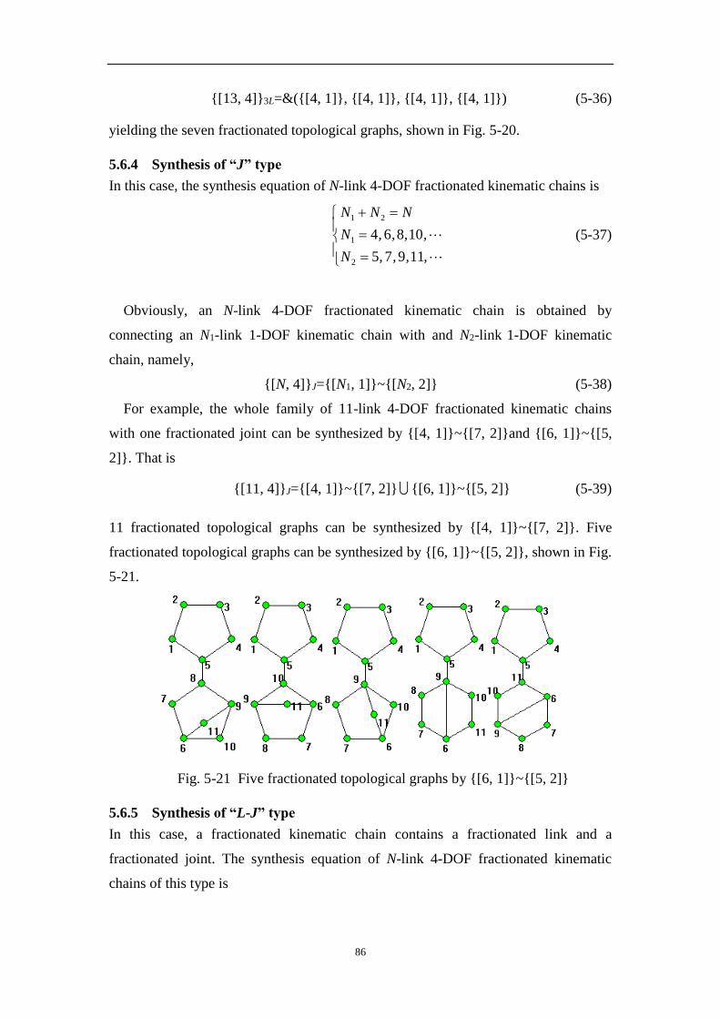
86
{[13, 4]}3L=&({[4, 1]}, {[4, 1]}, {[4, 1]}, {[4, 1]}) (5-36)
yielding the seven fractionated topological graphs, shown in Fig. 5-20.
5.6.4 Synthesis of “J” type
In this case, the synthesis equation of N-link 4-DOF fractionated kinematic chains is
,,,,N
,,,,N
NNN
11975
10864
2
1
21
(5-37)
Obviously, an N-link 4-DOF fractionated kinematic chain is obtained by
connecting an N1-link 1-DOF kinematic chain with and N2-link 1-DOF kinematic
chain, namely,
{[N, 4]}J={[N1, 1]}~{[N2, 2]} (5-38)
For example, the whole family of 11-link 4-DOF fractionated kinematic chains
with one fractionated joint can be synthesized by {[4, 1]}~{[7, 2]}and {[6, 1]}~{[5,
2]}. That is
{[11, 4]}J={[4, 1]}~{[7, 2]} {[6, 1]}~{[5, 2]} (5-39)
11 fractionated topological graphs can be synthesized by {[4, 1]}~{[7, 2]}. Five
fractionated topological graphs can be synthesized by {[6, 1]}~{[5, 2]}, shown in Fig.
5-21.
Fig. 5-21 Five fractionated topological graphs by {[6, 1]}~{[5, 2]}
5.6.5 Synthesis of “L-J” type
In this case, a fractionated kinematic chain contains a fractionated link and a
fractionated joint. The synthesis equation of N-link 4-DOF fractionated kinematic
chains of this type is
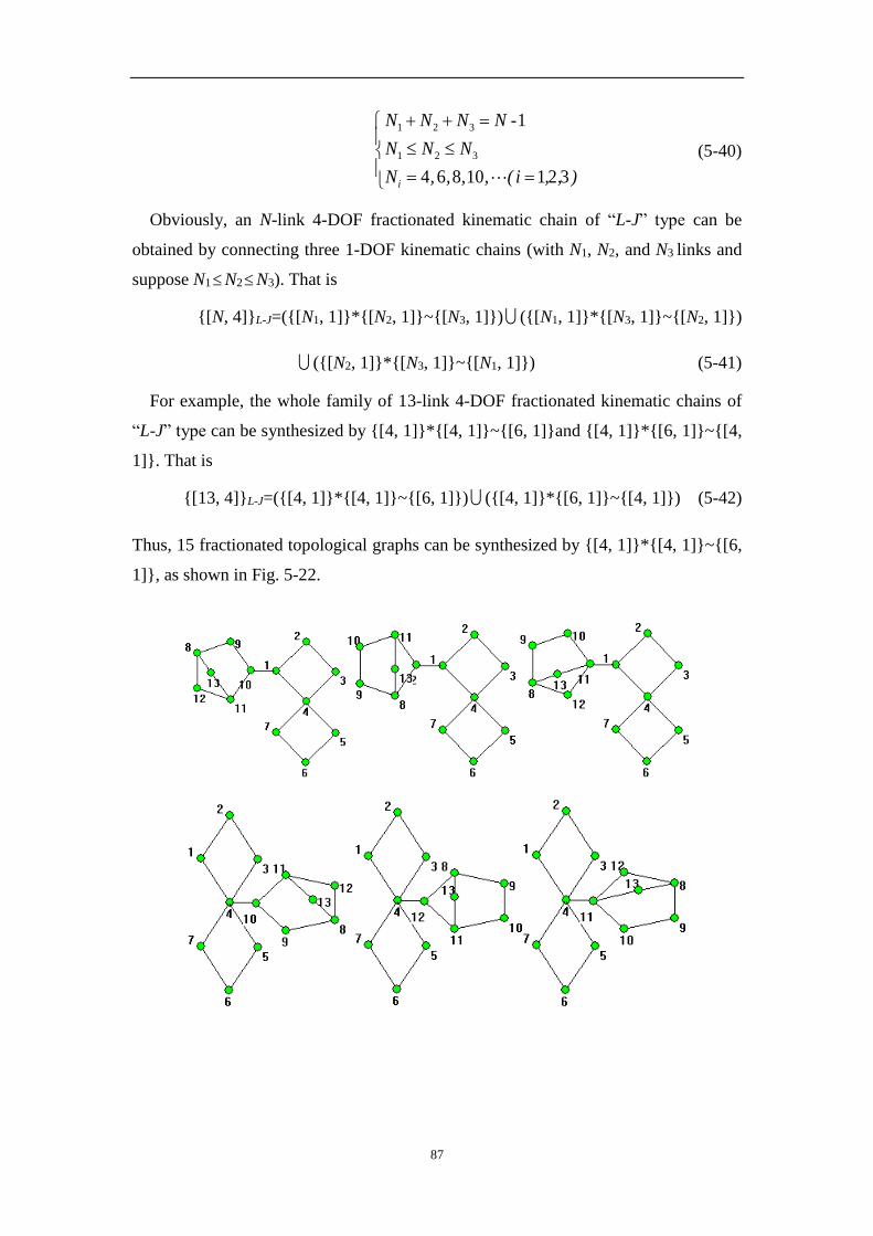
87
),,i(,,,,N
NNN
NNNN
i 32110864
1-
321
321
(5-40)
Obviously, an N-link 4-DOF fractionated kinematic chain of “L-J” type can be
obtained by connecting three 1-DOF kinematic chains (with N1, N2, and N3 links and
suppose N1N2N3). That is
{[N, 4]}L-J=({[N1, 1]}*{[N2, 1]}~{[N3, 1]}) ({[N1, 1]}*{[N3, 1]}~{[N2, 1]})
({[N2, 1]}*{[N3, 1]}~{[N1, 1]}) (5-41)
For example, the whole family of 13-link 4-DOF fractionated kinematic chains of
“L-J” type can be synthesized by {[4, 1]}*{[4, 1]}~{[6, 1]}and {[4, 1]}*{[6, 1]}~{[4,
1]}. That is
{[13, 4]}L-J=({[4, 1]}*{[4, 1]}~{[6, 1]}) ({[4, 1]}*{[6, 1]}~{[4, 1]}) (5-42)
Thus, 15 fractionated topological graphs can be synthesized by {[4, 1]}*{[4, 1]}~{[6,
1]}, as shown in Fig. 5-22.

88
Fig. 5-22 Fifteen fractionated topological graphs by {[4, 1]}*{[4, 1]}~{[6, 1]}
5.6.6 Synthesis of “J-V” type
In this case, a fractionated kinematic chain contains a fractionated joint and an
independent link. The synthesis equation of N-link 4-DOF fractionated kinematic
chains of this type is
),i(,,,,N
NN
NNN
i 2110864
1-
21
21
(5-43)
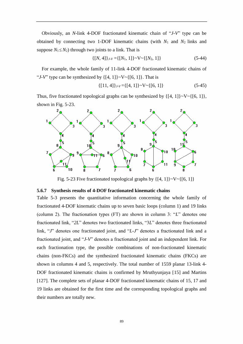
89
Obviously, an N-link 4-DOF fractionated kinematic chain of “J-V” type can be
obtained by connecting two 1-DOF kinematic chains (with N1 and N2 links and
suppose N1N2) through two joints to a link. That is
{[N, 4]}J-V ={[N1, 1]}~V~{[N2, 1]} (5-44)
For example, the whole family of 11-link 4-DOF fractionated kinematic chains of
“J-V” type can be synthesized by {[4, 1]}~V~{[6, 1]}. That is
{[11, 4]}J-V ={[4, 1]}~V~{[6, 1]} (5-45)
Thus, five fractionated topological graphs can be synthesized by {[4, 1]}~V~{[6, 1]},
shown in Fig. 5-23.
Fig. 5-23 Five fractionated topological graphs by {[4, 1]}~V~{[6, 1]}
5.6.7 Synthesis results of 4-DOF fractionated kinematic chains
Table 5-3 presents the quantitative information concerning the whole family of
fractionated 4-DOF kinematic chains up to seven basic loops (column 1) and 19 links
(column 2). The fractionation types (FT) are shown in column 3: “L” denotes one
fractionated link, “2L” denotes two fractionated links, “3L” denotes three fractionated
link, “J” denotes one fractionated joint, and “L-J” denotes a fractionated link and a
fractionated joint, and “J-V” denotes a fractionated joint and an independent link. For
each fractionation type, the possible combinations of non-fractionated kinematic
chains (non-FKCs) and the synthesized fractionated kinematic chains (FKCs) are
shown in columns 4 and 5, respectively. The total number of 1559 planar 13-link 4-
DOF fractionated kinematic chains is confirmed by Mruthyunjaya [15] and Martins
[127]. The complete sets of planar 4-DOF fractionated kinematic chains of 15, 17 and
19 links are obtained for the first time and the corresponding topological graphs and
their numbers are totally new.
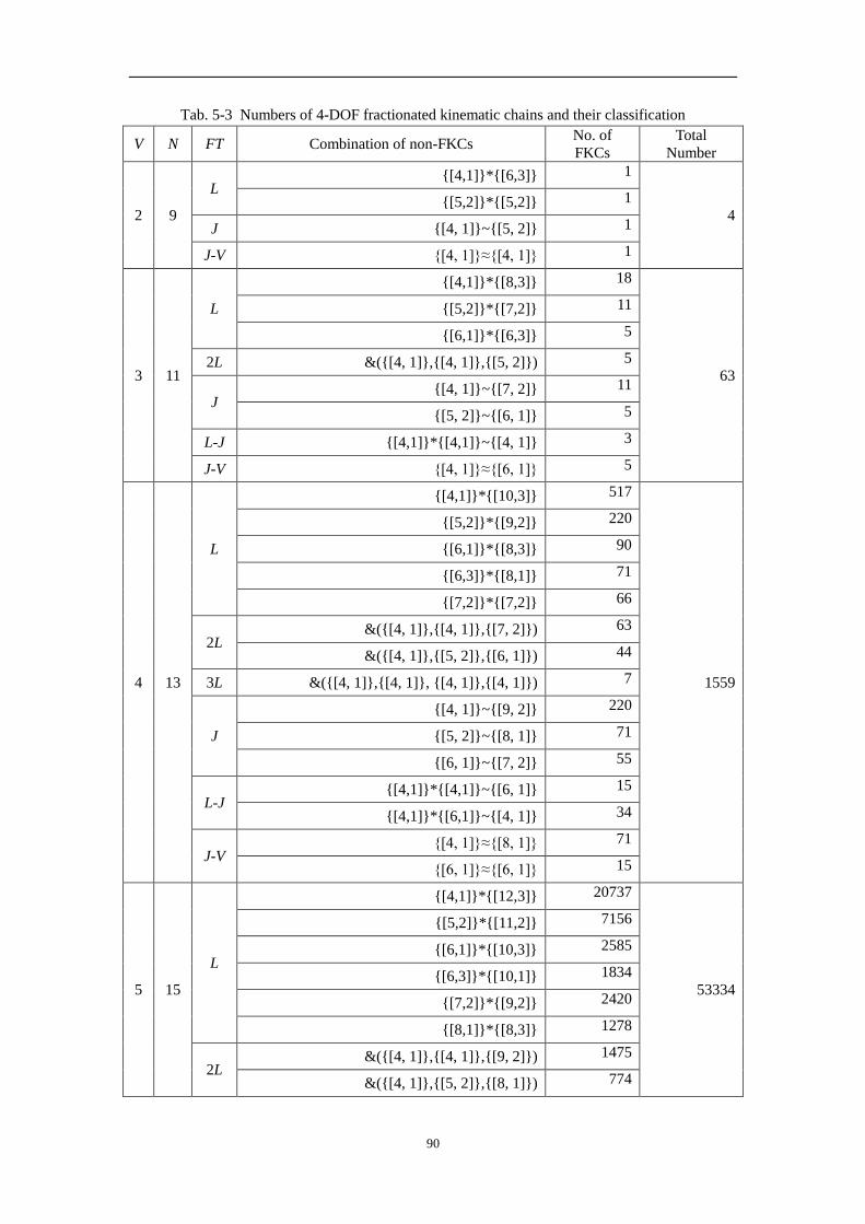
90
Tab. 5-3 Numbers of 4-DOF fractionated kinematic chains and their classification
V N FT Combination of non-FKCs No. of
FKCs
Total
Number
2 9
L {[4,1]}*{[6,3]} 1
4 {[5,2]}*{[5,2]} 1
J {[4, 1]}~{[5, 2]} 1
J-V {[4, 1]}≈{[4, 1]} 1
3 11
L
{[4,1]}*{[8,3]} 18
63
{[5,2]}*{[7,2]} 11
{[6,1]}*{[6,3]} 5
2L &({[4, 1]},{[4, 1]},{[5, 2]}) 5
J {[4, 1]}~{[7, 2]} 11
{[5, 2]}~{[6, 1]} 5
L-J {[4,1]}*{[4,1]}~{[4, 1]} 3
J-V {[4, 1]}≈{[6, 1]} 5
4 13
L
{[4,1]}*{[10,3]} 517
1559
{[5,2]}*{[9,2]} 220
{[6,1]}*{[8,3]} 90
{[6,3]}*{[8,1]} 71
{[7,2]}*{[7,2]} 66
2L &({[4, 1]},{[4, 1]},{[7, 2]}) 63
&({[4, 1]},{[5, 2]},{[6, 1]}) 44
3L &({[4, 1]},{[4, 1]}, {[4, 1]},{[4, 1]}) 7
J
{[4, 1]}~{[9, 2]} 220
{[5, 2]}~{[8, 1]} 71
{[6, 1]}~{[7, 2]} 55
L-J {[4,1]}*{[4,1]}~{[6, 1]} 15
{[4,1]}*{[6,1]}~{[4, 1]} 34
J-V {[4, 1]}≈{[8, 1]} 71
{[6, 1]}≈{[6, 1]} 15
5 15
L
{[4,1]}*{[12,3]} 20737
53334
{[5,2]}*{[11,2]} 7156
{[6,1]}*{[10,3]} 2585
{[6,3]}*{[10,1]} 1834
{[7,2]}*{[9,2]} 2420
{[8,1]}*{[8,3]} 1278
2L &({[4, 1]},{[4, 1]},{[9, 2]}) 1475
&({[4, 1]},{[5, 2]},{[8, 1]}) 774
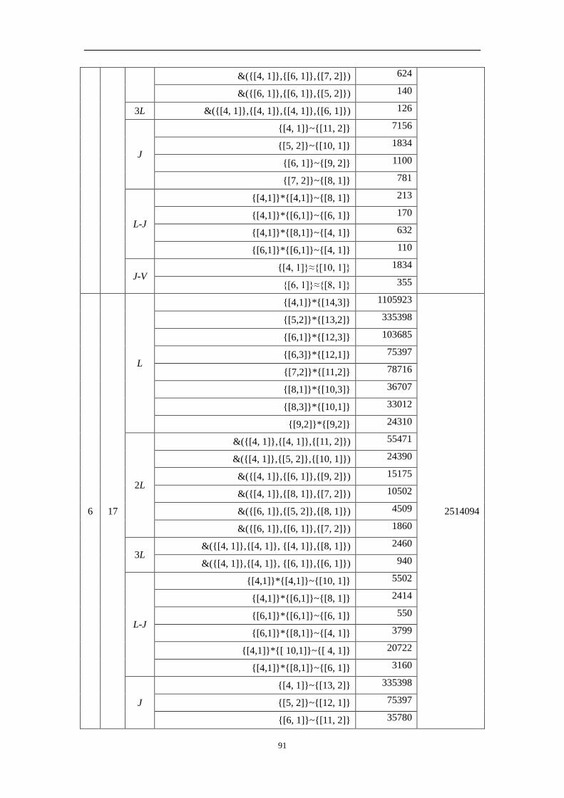
91
&({[4, 1]},{[6, 1]},{[7, 2]}) 624
&({[6, 1]},{[6, 1]},{[5, 2]}) 140
3L &({[4, 1]},{[4, 1]},{[4, 1]},{[6, 1]}) 126
J
{[4, 1]}~{[11, 2]} 7156
{[5, 2]}~{[10, 1]} 1834
{[6, 1]}~{[9, 2]} 1100
{[7, 2]}~{[8, 1]} 781
L-J
{[4,1]}*{[4,1]}~{[8, 1]} 213
{[4,1]}*{[6,1]}~{[6, 1]} 170
{[4,1]}*{[8,1]}~{[4, 1]} 632
{[6,1]}*{[6,1]}~{[4, 1]} 110
J-V {[4, 1]}≈{[10, 1]} 1834
{[6, 1]}≈{[8, 1]} 355
6 17
L
{[4,1]}*{[14,3]} 1105923
2514094
{[5,2]}*{[13,2]} 335398
{[6,1]}*{[12,3]} 103685
{[6,3]}*{[12,1]} 75397
{[7,2]}*{[11,2]} 78716
{[8,1]}*{[10,3]} 36707
{[8,3]}*{[10,1]} 33012
{[9,2]}*{[9,2]} 24310
2L
&({[4, 1]},{[4, 1]},{[11, 2]}) 55471
&({[4, 1]},{[5, 2]},{[10, 1]}) 24390
&({[4, 1]},{[6, 1]},{[9, 2]}) 15175
&({[4, 1]},{[8, 1]},{[7, 2]}) 10502
&({[6, 1]},{[5, 2]},{[8, 1]}) 4509
&({[6, 1]},{[6, 1]},{[7, 2]}) 1860
3L &({[4, 1]},{[4, 1]}, {[4, 1]},{[8, 1]}) 2460
&({[4, 1]},{[4, 1]}, {[6, 1]},{[6, 1]}) 940
L-J
{[4,1]}*{[4,1]}~{[10, 1]} 5502
{[4,1]}*{[6,1]}~{[8, 1]} 2414
{[6,1]}*{[6,1]}~{[6, 1]} 550
{[6,1]}*{[8,1]}~{[4, 1]} 3799
{[4,1]}*{[ 10,1]}~{[ 4, 1]} 20722
{[4,1]}*{[8,1]}~{[6, 1]} 3160
J
{[4, 1]}~{[13, 2]} 335398
{[5, 2]}~{[12, 1]} 75397
{[6, 1]}~{[11, 2]} 35780

92
{[7, 2]}~{[10, 1]} 20174
{[8, 1]}~{[9, 2]} 15620
J-V
{[4, 1]}≈{[12, 1]} 75397
{[6, 1]}≈{[10, 1]} 9170
{[8, 1]}≈{[8, 1]} 2556
7 19
L
{[4,1]}*{[16,3]} 74393277
154527061
{[5,2]}*{[15,2]} 20737954
{[6,1]}*{[14,3]} 4274510
{[6,3]}*{[14,1]} 5529615
{[7,2]}*{[13,2]} 3689378
{[8,1]}*{[12,3]} 1472327
{[8,3]}*{[12,1]} 1357146
{[9,2]}*{[11,2]} 1574320
{[10,1]}*{[10,3]} 948178
2L
&({[4, 1]},{[4, 1]},{[13, 2]}) 2950613
&({[4, 1]},{[5, 2]},{[12, 1]}) 1169661
&({[4, 1]},{[6, 1]},{[11, 2]}) 577794
&({[4, 1]},{[7, 2]},{[10, 1]}) 319642
&({[4, 1]},{[8, 1]},{[9, 2]}) 248309
&({[6, 1]},{[5, 2]},{[10, 1]}) 138456
&({[5, 2]},{ [8, 1]},{[8, 1]}) 37417
&({[6, 1]},{[6, 1]},{[9, 2]}) 43665
&({[6, 1]},{[7, 2]},{[8, 1]}) 59539
3L
&({[4, 1]},{[4, 1]}, {[4, 1]},{[10, 1]}) 85771
&({[4, 1]},{[4, 1]}, {[6, 1]},{[8, 1]}) 42106
&({[4, 1]},{[6, 1]}, {[6, 1]},{[6, 1]}) 4615
L-J
{[4,1]}*{[4,1]}~{[12, 1]} 226191
{[4,1]}*{[6,1]}~{[10, 1]} 62356
{[4,1]}*{[8,1]}~{[8, 1]} 44872
{[4,1]}*{[10,1]}~{[6, 1]} 103610
{[4,1]}*{[12,1]}~{[4, 1]} 1018867
{[6,1]}*{[6,1]}~{[8, 1]} 7810
{[6,1]}*{[8,1]}~{[6, 1]} 18995
{[6,1]}*{[10,1]}~{[4, 1]} 120116
{[8, 1]} *{[8,1]}~ {[4,1]} 32305
J
{[4, 1]}~{[15, 2]} 20737954
{[5, 2]}~{[14, 1]} 4274510
{[6, 1]}~{[13, 2]} 1676990

93
{[7, 2]}~{[12, 1]} 829367
{[8, 1]}~{[11, 2]} 533636
{[9, 2]}~{[10, 1]} 403480
J-V
{[4, 1]}≈{[14, 1]} 4274510
{[6, 1]}≈{[12, 1]} 376985
{[8, 1]}≈{[10, 1]} 130214
By this way, planar fractionated kinematic chains with more DOFs can also be
synthesized.
5.7 Summary
In this chapter, based on the structural synthesis of planar non-fractionated kinematic
chains and their atlas database, a fully-automatic approach is proposed to synthesize
the whole family of planar fractionated kinematic chains with specified number of
links and degrees of freedom. The synthesis equation of planar fractionated kinematic
chains is proposed, and for wanted fractionated kinematic chains, all possible
combination ways of non-fractionated kinematic chains can be obtained according to
the synthesis equation. Isomorphism-free combination algorithms of non-fractionated
kinematic chains are proposed. With this algorithm, isomorphism identification, one
of the most difficult problems in structural synthesis, is rendered unnecessary in the
synthesis of planar fractionated kinematic chains. The whole family of the kinematic
structures of planar fractionated planar mechanisms with up to seven basic loops (the
mechanisms synthesized so far with other methods contain only four basic loops) is
also given, showing the effectiveness of the method.

94
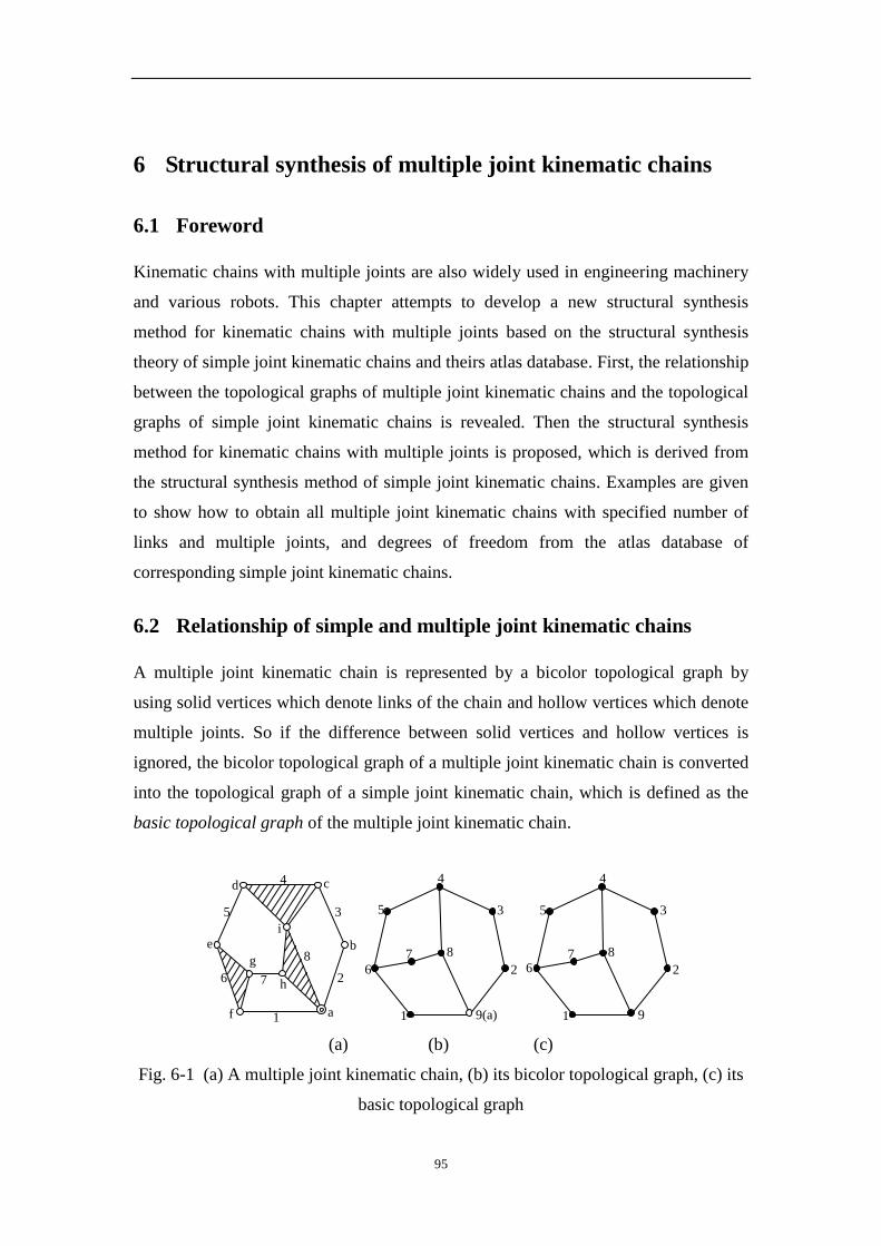
95
6 Structural synthesis of multiple joint kinematic chains
6.1 Foreword
Kinematic chains with multiple joints are also widely used in engineering machinery
and various robots. This chapter attempts to develop a new structural synthesis
method for kinematic chains with multiple joints based on the structural synthesis
theory of simple joint kinematic chains and theirs atlas database. First, the relationship
between the topological graphs of multiple joint kinematic chains and the topological
graphs of simple joint kinematic chains is revealed. Then the structural synthesis
method for kinematic chains with multiple joints is proposed, which is derived from
the structural synthesis method of simple joint kinematic chains. Examples are given
to show how to obtain all multiple joint kinematic chains with specified number of
links and multiple joints, and degrees of freedom from the atlas database of
corresponding simple joint kinematic chains.
6.2 Relationship of simple and multiple joint kinematic chains
A multiple joint kinematic chain is represented by a bicolor topological graph by
using solid vertices which denote links of the chain and hollow vertices which denote
multiple joints. So if the difference between solid vertices and hollow vertices is
ignored, the bicolor topological graph of a multiple joint kinematic chain is converted
into the topological graph of a simple joint kinematic chain, which is defined as the
basic topological graph of the multiple joint kinematic chain.
cd
i
h
g
b
af
e8
7 2
3
4
5
6
1 9(a)
3
4
5
8
6 2
7
1 9
3
4
5
8
6 2
7
1
(a) (b) (c)
Fig. 6-1 (a) A multiple joint kinematic chain, (b) its bicolor topological graph, (c) its
basic topological graph

96
For example, Fig. 6-1(a) is a 8-link 1-DOF kinematic chain with one multiple joint
and Fig. 6-1(b) is its bicolor topological graph. Fig. 6-1(b) becomes the topological
graph of a simple joint kinematic chain if its hollow vertex 9 is converted into a solid
vertex, shown in Fig. 6-1(c). Fig. 6-1(c) is the basic topological graph for the multiple
joint kinematic chain in Fig. 6-1(a).
For a multiple joint kinematic chain with one link grounded, the degrees of freedom
( BGF ) of its basic topological graph are
JF
JMN
JMJNFBG
]2-1)-[3
2-1)-3
(
)((
(6-1)
where N is the number of links, M is the number of kinematic pairs, J is the number of
multiple joints, and F is the DOFs of the multiple joint kinematic chain.
It can be seen that the DOFs ( BGF ) of the basic topological graph increase by J
compared with the DOFs ( F ) of the multiple joint kinematic chain.
The model of the bicolor topological graph enlightens us on a new synthesis
method of the structures of multiple joint kinematic chains: they may be synthesized
in batch directly based on the developed structural synthesis theories of the simple
joint kinematic chains and their atlas database. For example, in the topological graph
of a 9-link 2-DOF simple joint kinematic chain, if a vertex whose degree is greater
than or equal to 3 is converted into a hollow vertex, the new bicolor topological graph
of an 8-link 1-DOF multiple joint kinematic chain is obtained, and the corresponding
multiple joint kinematic chain is synthesized.
Fig. 6-2 (a) is a 10-link kinematic chain with two multiple joints. Its bicolor
topological graph and basic topological graph are shown in Fig. 6-2 (b) and (c),
respectively. Its characteristic perimeter topological graph and the characteristic
perimeter topological graph of its basic topological graph are shown in Fig. 6-2 (d)
and (e), respectively. It is clear that such a 10-link kinematic chain with 2 multiple
joints can be synthesized from the topological graphs of a 12-link 3-DOF simple joint
kinematic chain.
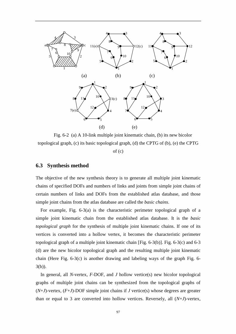
97
e
9
3
8 c
2
4
510
1
76
12(c)
34
8
9
6
7
11(e)
5 2
10
1
1211
34
8
9
6
7
5 2
10
1
(a) (b) (c)
9
8
7(e)
6 5
4
3(c)
2
1
12
1110
3
9
8
7
6 5
4
2
1
12
1110
(d) (e)
Fig. 6-2 (a) A 10-link multiple joint kinematic chain, (b) its new bicolor
topological graph, (c) its basic topological graph, (d) the CPTG of (b), (e) the CPTG
of (c)
6.3 Synthesis method
The objective of the new synthesis theory is to generate all multiple joint kinematic
chains of specified DOFs and numbers of links and joints from simple joint chains of
certain numbers of links and DOFs from the established atlas database, and those
simple joint chains from the atlas database are called the basic chains.
For example, Fig. 6-3(a) is the characteristic perimeter topological graph of a
simple joint kinematic chain from the established atlas database. It is the basic
topological graph for the synthesis of multiple joint kinematic chains. If one of its
vertices is converted into a hollow vertex, it becomes the characteristic perimeter
topological graph of a multiple joint kinematic chain [Fig. 6-3(b)]. Fig. 6-3(c) and 6-3
(d) are the new bicolor topological graph and the resulting multiple joint kinematic
chain (Here Fig. 6-3(c) is another drawing and labeling ways of the graph Fig. 6-
3(b)).
In general, all N-vertex, F-DOF, and J hollow vertice(s) new bicolor topological
graphs of multiple joint chains can be synthesized from the topological graphs of
(N+J)-vertex, (F+J)-DOF simple joint chains if J vertice(s) whose degrees are greater
than or equal to 3 are converted into hollow vertices. Reversely, all (N+J)-vertex,
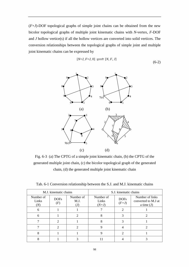
98
(F+J)-DOF topological graphs of simple joint chains can be obtained from the new
bicolor topological graphs of multiple joint kinematic chains with N-vertex, F-DOF
and J hollow vertice(s) if all the hollow vertices are converted into solid vertices. The
conversion relationships between the topological graphs of simple joint and multiple
joint kinematic chains can be expressed by
[N, F, J][N+J, F+J, J][N, F, J][N+J, F+J, J]
[N, F, J][N+J, F+J, J]
[N+J, F+J, 0] [N, F, J] (6-2)
8
7
6 5
4
3
29
1
8
7(e)
6 5
4
3
29
1
(a) (b)
9(e)
1
5
8
6
7
4
32
2
e
6
8
7
3
4
51
(c) (d)
Fig. 6-3 (a) The CPTG of a simple joint kinematic chain, (b) the CPTG of the
generated multiple joint chain, (c) the bicolor topological graph of the generated
chain, (d) the generated multiple joint kinematic chain
Tab. 6-1 Conversion relationship between the S.J. and M.J. kinematic chains
M.J. kinematic chains S.J. kinematic chains
Number of
Links
(N)
DOFs
(F)
Number of
M.J.
(J)
Number of
Links
(N+J)
DOFs
(F+J)
Number of links
converted to M.J at
a time (J)
6 1 1 7 2 1
6 1 2 8 3 2
7 2 1 8 3 1
7 2 2 9 4 2
8 1 1 9 2 1
8 1 3 11 4 3

99
8 3 1 9 4 1
9 2 1 10 3 1
8 1 2 10 3 2
11 2 1 12 3 1
10 1 2 12 3 2
11 4 1 12 5 1
12 1 1 13 2 1
13 2 1 14 3 1
14 1 1 15 2 1
15 2 1 16 3 1
16 1 1 17 2 1
(S.J.: simple joint; M.J.: multiple joint)
3
9
8
7
6 5
4
2
1
10
3
9
8
7
6 5
4
2
1
10
(a) (b)
10
9
3
45
86
27
1
9
4
3
2
1
7
8
6
5
(c) (d)
Fig. 6-4 (a) The CPTG of a simple joint chain , (b) the CPTG of the generated
multiple joint chain, (c) another form of (b), (d) the generated multiple joint kinematic
chain
Some of the conversion relationships are given in Tab.6-1. In the table, all the
distinct multiple joint kinematic chains with specified numbers of links(N), DOFs(F)
and multiple joints (J) can be generated from their corresponding simple joint chains.
For example, all 6-link 1-DOF 1-multiple joint kinematic chains can be generated
from all 7-link 2-DOF simple joint kinematic chains when all links whose degrees are

100
greater than or equal to 3 are converted into multiple joints, one link converted at a
time.
Not all the multiple joint kinematic chains synthesized with this method are valid.
Sometimes rigid sub-chains come into existence. For example, Fig. 6-4 (a) is the
characteristic perimeter topological graph of a simple joint kinematic chain from the
atlas database. If vertex 5 is converted into a hollow vertex, it becomes the
characteristic perimeter topological graph of a multiple joint kinematic chain [Fig. 6-4
(b)], which can also be drawn in the form of Fig. 6-4 (c). The generated multiple joint
kinematic chain is shown in Fig. 6-4 (d). Obviously, there exists a rigid sub-chain.
However, rigid sub-chains can be detected easily with the method in literature [115].
6.4 Unique representation and isomorphism identification
The isomorphism identification is also required with this synthesis method. Here the
characteristic number string (CNS) of bicolor topological graphs is proposed to
represent multiple joint kinematic chains uniquely and detect isomorphism in the
synthesis process. The steps to obtain the characteristic number string of bicolor
topological graphs are as follows.
1
2
3
4
5
6
7
8
910
Fig. 6-5 A bicolor topological graph
Step 1: Obtain the perimeter loops of a bicolor topological graph with the start
vertex of multiple joint.
In a bicolor topological graph, the loops with the most vertices or edges are defined
as its maximum loops. For example, the bicolor topological graph in Fig. 6-5 has two
maximum loops with the start vertex of four: the first is constituted by vertices
4,9,1,2,10,7,6,5 and the second is by vertices 4,3,2,1,8,7,6,5.
The degree-sequence of a maximum loop is the degree permutation of vertices
sequenced one by one from a starting vertex along the loop clockwise or
counterclockwise. In Fig. 6-5 the degree-sequence for the first maximum loop is
32332322, and the degree-sequence for the second is also 32332322.

101
A degree-sequence can be viewed as a number. For a bicolor topological graph, the
largest of the degree-sequences of the maximum loops is defined as the canonical
perimeter degree-sequence and the corresponding loop is defined as the perimeter
loop. Obviously, both maximum loops are perimeter loops in Fig. 6-5.
Step 2: Obtain the perimeter graph.
The perimeter graph bicolor topological graph is drawn as follows.
(1) Draw the perimeter loop as the outmost loop in the form of an equilateral
polygon.
(2) Put the remaining vertices of the graph inside the perimeter loop.
For example, the two perimeter graphs corresponding to the two perimeter loops in
Fig. 6-5 are shown in Fig. 6-6.
4
9
1
2
10
7
6
5
3
8
4
3
2
1
8
7
6
5
9
10
(a) (b)
Fig. 6-6 The two perimeter graphs for Fig. 6-5
Step 3: Obtain the canonical perimeter graphs and canonical adjacency matrices.
Assign natural numbers 1~t in turn to each vertex as its new label on the perimeter
loop according to the perimeter degree-sequence. An inner sub-chain can be viewed
as a directed path. Here, the starting vertex of the inner sub-chain is assumed to
connect with the vertex on the perimeter loop which has the smaller new label. Here,
relabel the vertices on inner sub-chains by the following rules in turn.
(1) Relabel the inner sub-chain containing a vertex with the biggest degree first,
then the inner sub-chain containing a vertex with the second biggest degree, and so on.
(2) Relabel the inner sub-chain containing the most vertices first, and so on.
(3) Relabel the inner sub-chain whose starting vertex is connected with the vertex
on the perimeter loop having the smallest new label first, and so on.
(4) Relabel the inner sub-chain whose end vertex is connected with the vertex on
the perimeter loop having the smallest new label first, and so on.
(5) In an inner sub-chain, the relabel sequence is from the starting vertex to the
end vertex.

102
The perimeter graph labeled in the above way is defined as the canonical perimeter
graph. The corresponding adjacency matrix is defined as the canonical adjacency
matrix. The canonical perimeter graphs for Figs. 6-6 (a) and (b) are the same, and
their shared canonical perimeter graph is shown in Fig. 6-7.
1
2
3
4
5
6
7
8
9
10
Fig. 6-7 The shared canonical perimeter graph for the two graphs in Fig. 6-6
Step 4: Obtain characteristic number string.
From a bicolor topological graph, the matrix with the largest value of the number
string concatenated by the upper-right triangle of the matrix among the canonical
adjacency matrices is defined as the characteristic adjacency matrix (CAM), and the
corresponding canonical perimeter graph is defined as the characteristic perimeter
graph(CPG).
Obviously, the characteristic adjacency matrix of a bicolor topological graph is
unique. The number string concatenated by the upper-right triangle of the
characteristic adjacency matrix is defined as the characteristic number string (CNS),
which is used to identify isomorphism in the synthesis process.
For only one canonical perimeter graph exists for the bicolor topological graph in
Fig. 6-5, the canonical perimeter graph is also the characteristic perimeter graph. The
characteristic adjacency matrix and characteristic number string of the graph in Fig. 6-
5 are
3 1 0 0 0 0 0 1 1 0
1 0 1 0 0 0 0 0 0 0
0 1 0 1 0 0 0 0 0 1
0 0 1 0 1 0 0 0 1 0
0 0 0 1 0 1 0 0 0 0
0 0 0 0 1 0 1 0 0 1
0 0 0 0 0 1 0 1 0 0
1 0 0 0 0 0 1 0 0 0
1 0 0 1 0 0 0 0 0 0
0 0 1 0 0 1 0 0 0 0
CAM
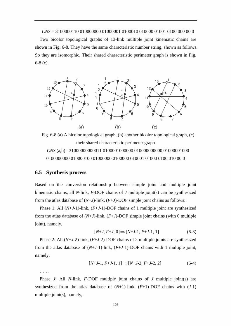
103
CNS = 3100000110 010000000 01000001 0100010 010000 01001 0100 000 00 0
Two bicolor topological graphs of 13-link multiple joint kinematic chains are
shown in Fig. 6-8. They have the same characteristic number string, shown as follows.
So they are isomorphic. Their shared characteristic perimeter graph is shown in Fig.
6-8 (c).
1 2
3
4
5
6
78
9
10
11
12
13
14
12
3
4
5
6
78
9
1
0
1
1
1
2
1
3
1
4
2
113
12
11
10
9
8 7
6
5
4
314
(a) (b) (c)
Fig. 6-8 (a) A bicolor topological graph, (b) another bicolor topological graph, (c)
their shared characteristic perimeter graph
CNS (a,b)= 31000000000011 0100001000000 010000000000 01000001000
0100000000 010000100 01000000 0100000 010001 01000 0100 010 00 0
6.5 Synthesis process
Based on the conversion relationship between simple joint and multiple joint
kinematic chains, all N-link, F-DOF chains of J multiple joint(s) can be synthesized
from the atlas database of (N+J)-link, (F+J)-DOF simple joint chains as follows:
Phase 1: All (N+J-1)-link, (F+J-1)-DOF chains of 1 multiple joint are synthesized
from the atlas database of (N+J)-link, (F+J)-DOF simple joint chains (with 0 multiple
joint), namely,
[N+J, F+J, 0] [N+J-1, F+J-1, 1] (6-3)
Phase 2: All (N+J-2)-link, (F+J-2)-DOF chains of 2 multiple joints are synthesized
from the atlas database of (N+J-1)-link, (F+J-1)-DOF chains with 1 multiple joint,
namely,
[N+J-1, F+J-1, 1] [N+J-2, F+J-2, 2] (6-4)
……
Phase J: All N-link, F-DOF multiple joint chains of J multiple joint(s) are
synthesized from the atlas database of (N+1)-link, (F+1)-DOF chains with (J-1)
multiple joint(s), namely,

104
[N+1, F+1, J-1] [N, F, J] (6-5)
Hence all required N-link, F-DOF chains of J multiple joint(s) are synthesized.
The synthesis steps involved in each phase are similar, so here only those in the
first phase are given in detail as an illustration.
For a specified synthesis task
Determine the group of the basic topological graphs G={G1,G2, …,Gw}, k=1
Obtain all the new bicolor topological graphs from Gk
Convert vertex vi in set Sk2 into a hollow vertex
Determine the vertex set Sk1={v1,v2,…,vr}for Gk
Determine the vertex set Sk2={v1,v2,…,vp}
Determine whether
i=p? i=i+1
Determine whether
k=w? k=k+1
Obtain all required new bicolor topological
graphs and corresponding multiple joint chains
Y
Y
N
N
Isomorphism identification
Rigid sub-chain detection
Fig. 6-9 The synthesis flowchart with the unified structural synthesis mothod
Step 1: Determine the basic topological graph group, G={G1,G2,…,Gw}, of the
simple joint kinematic chains according to the specified task and [N+J, F+J,
0] [N+J-1, F+J-1, 1]. Suppose k=1.
Step 2: Get all the vertices in graph Gk from group G whose degrees are greater
than or equal to 3 into the vertex set Sk1={v1,v2,…,vr}.
Step 3: Determine the vertex set Sk2={v1,v2,…,vp} by deleting from set Sk1 all solid
vertices in the loops whose sub-dimensions (i.e. the number of solid vertices the loop
contains) are 4.

105
Step 4: Convert vertex vi in Sk2 into a hollow vertex.
Step 5: Detect rigid sub-chains in the obtained new bicolor topological graph. If
there are no rigid sub-chains, store the graph; otherwise delete it.
Step 6: Obtain the characteristic number string of the new bicolor topological graph
and use it to detect isomorphism. If it is the same with any of the former ones, delete
it; otherwise store the graph.
Step 7: Determine whether i=p. If i=p, then all the new bicolor topological graphs
from the graph Gk are obtained; go to step 8. Otherwise i=i+1, and return to step 4.
Step 8: Determine whether k=w. If k=w, then all the new bicolor topological graphs
derivable from group G are obtained; end the phase. Otherwise k=k+1, and return to
step 2.
The synthesis flowchart of kinematic chains with one multiple joint is shown in
Fig. 6-9. If chains of n multiple joints are to be synthesized, take the new bicolor
topological graphs of the synthesized (n-1) multiple joint chains as the basic
topological graph group, and repeat the synthesis steps 1~8.
These procedures followed, all the multiple joint kinematic chains with certain
specifications can be synthesized in batch.
For example, the synthesis of all 8-link, 1-DOF kinematic chains with one multiple
joint can be generated from the atlas database of 9-link, 2-DOF simple joint kinematic
chains, that is
[9, 2, 0] [8, 1, 1]
Altogether 22 distinct topological graphs of 8-link, 1-DOF kinematic chains with
one multiple joint are generated, shown in Fig. 6-10, and the corresponding 22
multiple joint kinematic chains are shown in Fig. 6-11.
Another example, the synthesis of all 8-link 1-DOF kinematic chains with 2
multiple joints can be generated from the atlas database of 10-link, 3-DOF simple
joint kinematic chains. Two synthesis phases are involved: first, all 9-link, 2-DOF
chains of one multiple joint are synthesized from the atlas database of 10-link, 3-DOF
simple joint chains (with zero multiple joint), namely,
[10, 3, 0] [9, 2, 1]
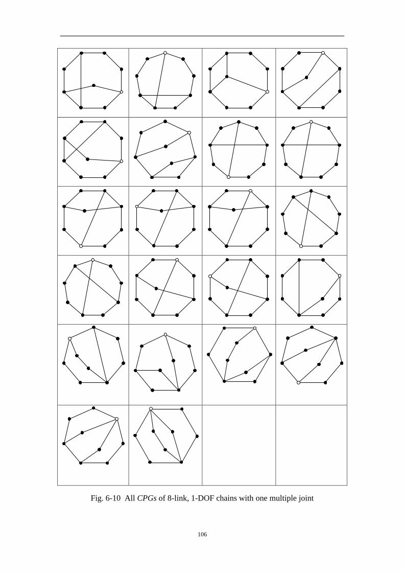
106
Fig. 6-10 All CPGs of 8-link, 1-DOF chains with one multiple joint

107
Fig. 6-11 22 8-link, 1-DOF kinematic chains with one multiple joint
Second, all 8-link, 1-DOF chains of two multiple joints are synthesized from the
atlas database of 9-link, 2-DOF chains with one multiple joint, namely,
[9, 2, 1] [8, 1, 2]
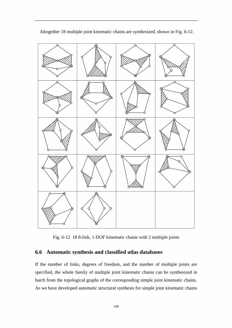
108
Altogether 18 multiple joint kinematic chains are synthesized, shown in Fig. 6-12.
Fig. 6-12 18 8-link, 1-DOF kinematic chains with 2 multiple joints
6.6 Automatic synthesis and classified atlas databases
If the number of links, degrees of freedom, and the number of multiple joints are
specified, the whole family of multiple joint kinematic chains can be synthesized in
batch from the topological graphs of the corresponding simple joint kinematic chains.
As we have developed automatic structural synthesis for simple joint kinematic chains
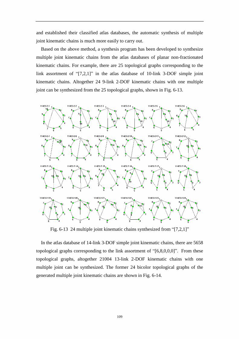
109
and established their classified atlas databases, the automatic synthesis of multiple
joint kinematic chains is much more easily to carry out.
Based on the above method, a synthesis program has been developed to synthesize
multiple joint kinematic chains from the atlas databases of planar non-fractionated
kinematic chains. For example, there are 25 topological graphs corresponding to the
link assortment of “[7,2,1]” in the atlas database of 10-link 3-DOF simple joint
kinematic chains. Altogether 24 9-link 2-DOF kinematic chains with one multiple
joint can be synthesized from the 25 topological graphs, shown in Fig. 6-13.
Fig. 6-13 24 multiple joint kinematic chains synthesized from “[7,2,1]”
In the atlas database of 14-link 3-DOF simple joint kinematic chains, there are 5658
topological graphs corresponding to the link assortment of “[6,8,0,0,0]”. From these
topological graphs, altogether 21004 13-link 2-DOF kinematic chains with one
multiple joint can be synthesized. The former 24 bicolor topological graphs of the
generated multiple joint kinematic chains are shown in Fig. 6-14.

110
Fig. 6-14 Excerpt of 21004 multiple joint kinematic chains from “[6,8,0,0,0]”
At present, multiple joint kinematic chains with no more than 10 links were
synthesized and reported by other methods [15, 57, 128]. However, the whole family
of multiple joint kinematic chains with up to 16 links can be synthesized by the
method.
Table 6-2 presents the quantitative information concerning the bicolor topological
graphs for 9-link 2-DOF kinematic chains with one multiple joint. The total number
of the bicolor topological graphs is 79. All the bicolor topological graphs are
classified according to their link assortment (column 2). For each link assortment, the
numbers of the multiple edges of the bicolor topological graphs are used to further
classify bicolor topological graphs (see columns 3 and 4). The total numbers of
bicolor topological graphs corresponding to link assortment are shown in column 5.
Tables 6-3, 6-4, 6-5 and 6-6 display the quantitative information for the atlas
databases of 1-DOF one multiple joint kinematic chains of 8, 10, 12 and 14 links,
respectively. The total numbers of the topological graphs are 22, 763, 38880, and
2580435, respectively.
The total quantitative information for the atlas databases of one multiple joint
kinematic chains with up to 16 links is given in Tab. 6-7. The multiple joint kinematic
chains with more than 10 links are synthesized here for the first time.

111
Tab. 6-2 Numbers of 9-link 2-DOF kinematic chains with one multiple joint
No. Link
assortment
No. of
Multi-edges
No. of
multiple joint
kinematic chains
Total number
1 [6,4,0] 0 38
53 2 15
2 [7,2,1] 2 24 24
3 [8,0,2] 3 2 2
Tab. 6-3 Numbers of 8-link 1-DOF kinematic chains with one multiple joint
No. Link
assortment
No. of
Multi-edges
No. of
multiple joint kinematic chains Total number
1 [5,4,0] 0 13
15 2 2
2 [6,2,1] 2 6 6
3 [7,0,2] 3 1 1
Tab. 6-4 Numbers of 10-link 1-DOF kinematic chains with one multiple joint
No. Link
assortment
No. of
Multi-edges
No. of
multiple joint kinematic chains Total number
1 [5,6,0,0]
0 214
252 1 33
2 5
2 [6,4,1,0]
0 181
371 1 162
2 28
3 [7,2,2,0]
1 70
98 2 20
3 8
4 [8,0,3,0] 3 2 2
5 [7,3,0,1] 2 28 28
6 [8,1,1,1] 3 11 11
7 [9,0,0,2] 4 1 1
Tab. 6-5 Numbers of 12-link 1-DOF kinematic chains with one multiple joint
No. Link
assortment
No. of
Multi-edges
No. of
multiple joint kinematic chains Total number
1 [5,8,0,0,0] 0 4102 4597

112
1 472
2 23
2 [6,6,1,0,0]
0 10954
15502 1 4200
2 342
3 6
3 [7,4,2,0,0]
0 5171
11529 1 5131
2 1172
3 55
4 [8,2,3,0,0]
0 404
1890 1 753
2 665
3 68
5 [9,0,4,0,0] 2 32
34 3 2
6 [7,5,0,1,0]
0 604
2509 1 1599
2 284
3 22
7 [8,3,1,1,0]
1 1327
2237 2 730
3 180
8 [9,1,2,1,0]
2 146
235 3 81
4 8
9 [9,2,0,2,0]
2 70
104 3 26
4 8
10 [A,0,1,2,0] 4 4 4
11 [8,4,0,0,1] 2 111
135 3 24
12 [9,2,1,0,1] 3 86 86
13 [A,0,2,0,1] 4 6 6
14 [A,1,0,1,1] 4 11 11
15 [B,0,0,0,2] 5 1 1
(In link assortment array, A=10, B=11, C=12, etc.)

113
Tab. 6-6 Numbers of 14-link 1-DOF kinematic chains with one multiple joint
No. Link
assortment
No. of
Multi-edges
No. of
multiple joint kinematic chains Total number
1 [5,A,0,0,0,0]
0 81880
89374 1 7296
2 198
2 [6,8,1,0,0,0]
0 444316
550376 1 100638
2 5360
3 62
3 [7,6,2,0,0,0]
0 555489
861015 1 270848
2 33760
3 918
4 [8,4,3,0,0,0]
0 178263
400409
1 171006
2 47857
3 3275
4 8
5 [9,2,4,0,0,0]
0 11791
46832
1 20065
2 12828
3 2075
4 73
6 [A,0,5,0,0,0]
0 155
622 2 372
3 81
4 14
7 [7,7,0,1,0,0]
0 76990
145096 1 61621
2 6218
3 267
8 [8,5,1,1,0,0]
0 92415
288594
1 151315
2 41469
3 3373
4 22

114
9 [9,3,2,1,0,0]
0 15070
115687
1 56208
2 36876
3 7299
4 234
10
[A,1,3,1,0,0]
1 2519
7768 2 3033
3 2046
4 170
11 [9,4,0,2,0,0]
0 1187
18908
1 8805
2 7398
3 1443
4 75
12 [A,2,1,2,0,0]
1 1353
7827 2 3946
3 2212
4 316
13 [B,0,2,2,0,0]
3 192
228 4 28
5 8
14 [B,1,0,3,0,0] 3 58
99 4 41
15 [8,6,0,0,1,0]
0 2035
16537 1 10012
2 4217
3 273
16 [9,4,1,0,1,0]
1 8756
21505 2 10607
3 2044
4 98
17 [A,2,2,0,1,0]
2 3152
4845 3 1368
4 325
18 [B,0,3,0,1,0] 3 54
95 4 41
19 [A,3,0,1,1,0] 2 1442 2524
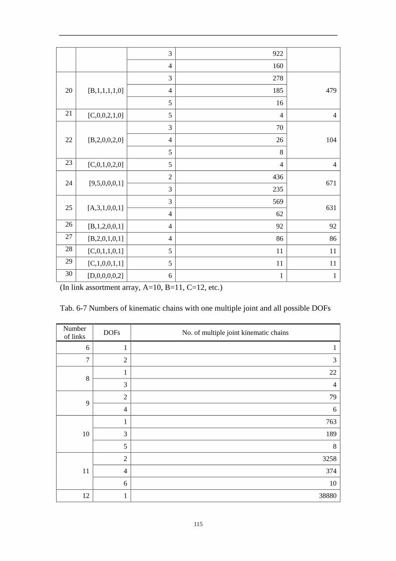
115
3 922
4 160
20 [B,1,1,1,1,0]
3 278
479 4 185
5 16
21 [C,0,0,2,1,0] 5 4 4
22 [B,2,0,0,2,0]
3 70
104 4 26
5 8
23 [C,0,1,0,2,0] 5 4 4
24 [9,5,0,0,0,1] 2 436
671 3 235
25 [A,3,1,0,0,1] 3 569
631 4 62
26 [B,1,2,0,0,1] 4 92 92
27 [B,2,0,1,0,1] 4 86 86
28 [C,0,1,1,0,1] 5 11 11
29 [C,1,0,0,1,1] 5 11 11
30 [D,0,0,0,0,2] 6 1 1
(In link assortment array, A=10, B=11, C=12, etc.)
Tab. 6-7 Numbers of kinematic chains with one multiple joint and all possible DOFs
Number
of links DOFs No. of multiple joint kinematic chains
6 1 1
7 2 3
8 1 22
3 4
9 2 79
4 6
10
1 763
3 189
5 8
11
2 3258
4 374
6 10
12 1 38880

116
3 9595
5 664
7 12
13
2 182628
4 23270
6 1087
8 15
14
1 2580435
3 604965
5 49820
7 1685
9 17
15
2 12935612
4 1662457
6 97603
8 2501
10 20
16
3 46268464
5 4037727
7 178768
9 3584
11 23
6.7 Summary
In this chapter, based on the structural synthesis theory of simple joint kinematic
chains and their atlas database, a new structural synthesis method of multiple joint
kinematic chains is proposed. The inter-conversion of the bicolor topological graphs
of multiple joint kinematic chains and the topological graphs of simple joint kinematic
chains is analysed. All multiple joint kinematic chains with specified numbers of links
and degrees of freedom can be synthesized from the atlas database of corresponding
simple joint kinematic chains. The whole family of multiple joint kinematic chains
with up to 16 links is obtained for the first time, far more than other methods
applicable only to multiple joint kinematic chains with no more than 10 links.

117
7 Conceptual creative design of mechanisms
7.1 Foreword
The first phase in the design of a product is the conceptual design in which the designer
explores as many and diverse design concepts as possible. Traditionally it was accomplished
on the designer’s intuition, ingenuity and experience. Later, some systematic methods were
proposed to generate feasible mechanisms for a given design task [5,129,130]. However, the
mechanisms generated with these methods are relatively simple in terms of the structures. In
this chapter, based on the established classified atlas databases of planar kinematic chains
with simple and multiple joints, a systematic method is proposed to generate all feasible
mechanisms for both simple and complex mechanisms. More complex mechanisms are
created in this way, such as 2-DOF main mechanisms for road tractors, 3-DOF hydraulic
robots and 6-DOF forging manipulators, provided as examples to demonstrate the
effectiveness of the method.
7.2 Design procedure
As we have known, design is the creation of synthesized solutions in the form of products or
systems that satisfy customer’s requirements [5]. In mechanical design the conceptual creative
design can be regarded as the mapping of the customer’s requirements into one or several
mechanisms. When a specified design task is given, the designer tries to make the best of his
knowledge and the information available to transform the design task into detailed design
specifications, such as knowledge of the existing mechanisms, relative mechanisms, or some
preliminary ideas if no relative mechanisms are available. Design specifications are usually of
three coherent categories, namely functional requirements, structural characteristics and
design constraints [129,130]. The main goal is to transform as many of the design
specifications of these three categories as possible into the selection constraints. Once the
selection constraints are given, search automatically all possible mechanisms in the
established classified atlas databases. The designer may have to search several times until all
selection constraints are considered and all possible mechanisms are obtained. Then the
obtained mechanisms are evaluated against the remaining design specifications, those that
cannot meet these requirements are ruled out, and the rest constitutes a complete set of the
feasible mechanisms for this design task. Hence the creative design of mechanisms is fulfilled
with a systematic method, which is based strictly on the structural synthesis and classified
atlas databases of simple and multiple joint kinematic chains. The main steps of the creative
design method can be outlined as [5]:
Step 1: Identify design specifications according to the customer’s requirements.
Step 2: Determine structural characteristics that meet the design specifications based on
existing mechanisms, relative mechanisms, or preliminary ideas.

118
Structural characteristics usually include the number of links, degrees of freedom (DOF),
the nature of motion (i.e. planar, spherical or spatial mechanism), the fractionated types (link-
fractionated, joint-fractionated, etc.), the number of basic loops and the admissible types of
joints, and so on.
Step 3: Determine functional requirements that meet the design specifications based on
existing or relative mechanisms or preliminary ideas.
Functional requirements are defined as “the general input/output relationship of a
mechanism whose purpose is to perform a task” [131] and the “Motion requirements of a set
of functioning links, such as the ground, input and output links” [130].
Customer’s requirements
Selection constrains
Functional requirements
All possible mechanisms
Existing, relative mechanisms,
preliminary ideas
All feasible mechanisms
Design specifications
Structural characteristics
Other design constrains
Classified atlas databases
Fig. 7-1 The procedure of the creative design based on classified atlas databases
Step 4: Determine other design constraints that meet the design specifications based on
existing or relative mechanisms or preliminary ideas.
Design specifications based on particular engineering reasoning and imposing restrictions
on the mechanism are considered as other design constraints.
Step 5: Choose those structural characteristics, functional requirements and design
constraints which can be represented in mathematical forms to formulate the selection
constraints.
Step 6: Search automatically all possible mechanisms that safisfy the selection constraints
in the classified atlas databases.
Step 7: Evaluate all the obtained mechanisms against the remaining structural
characteristics, functional requirements and other design constraints, and rule out those
invalid.

119
After accomplishing these steps, all feasible mechanisms for a certain design task are
obtained hence.
A flowchart for the creative design with this method is shown in Fig. 7-1.
7.3 Creative design of 2-DOF mechanisms for road tractors
Consider the road tractor shown in Fig. 1-1(a) [13]. Its main mechanism is a 2-DOF link-
fractionated mechanism with 11 links. One can get all feasible mechanisms for this type of
road tractor with the above method.
The structural characteristics for the main mechanism are shown in Tab.7-1, where the
fractionated type is specified as SC1, the number of links as SC2 , the degrees of freedom as
SC3, the nature of motion as SC4, the admissible types of joints as SC5 and the number of
basic loops as SC6 .
Tab. 7-1 Structural characteristics of the main mechanism for Fig. 1-1(a)
No. Structural characteristics
SC1 The mechanism is link-fractionated.
SC2 The number of links is 11.
SC3 The mechanism has two DOFs.
SC4 The mechanism is confined to planar nature of motion, namely d equals three.
SC5 The type of joints is limited to revolute joints and prismatic joints only.
SC6 There are four basic loops.
The functional requirements for the main mechanism are shown in Tab.7-2. The
assortments of the frame and the output links are specified as FR1 and FR2. The relationships
of the output link and the fractionated link are specified as FR3 and FR4.
Tab. 7-2 Functional requirements for the main mechanism for Fig. 1-1(a)
No. Functional requirements
FR 1 The frame link is a multiple-pair link.
FR 2 The output link is a binary link.
FR 3 The output link is connected with the fractionated link.
FR 4 The fractionated link is connected with the frame link.
Binary vertices in a topological graph may be connected in series to form a binary path.
The first and last vertices of a binary path are necessarily connected to nonbinary vertices.
The number of binary vertices in a binary path is defined as the length of the binary path.
Binary path of length 0, 1, 2 and 3 are called the E, Z, D and V path, respectively.
The other design constraints for the main mechanism are shown in Tab.7-3. The
mechanism is driven by two hydraulic cylinders, so there are two D-paths in the tological
graph of the mechanism, specified as OC1. Each fractionated part has at least one DOF, so

120
each part has a prismatic joint, specified as OC2. Obviously, the output link and the frame
link cannot be placed at the same fractionated part, specified as OC3.
Tab. 7-3 Other design constraints for the main mechanism for Fig. 1-1(a)
No. Other design constraints
OC 1 There are two D-paths.
OC 2 Each fractionated part has one hydraulic cylinder (prismatic joint).
OC 3 The output link and the frame link cannot be placed at the same fractionated part.
OC 4 There are no useless (redundant) sub-structures.
The selection constraints are constituted by SC1~SC4, SC6, FR1~ FR4 and OC1~OC2.
According to SC1, SC2, SC3, SC4 and SC6, all the required kinematic structures can be
obtained from the atlas database of 11-link 2-DOF fractionated kinematic chains with the
combination of two 6-link 1-DOF kinematic chains, shown in Fig. 7-2.
Fig. 7-2 All topological graphs in the class of {[6,1]}*{[6,1]}
According to OC1 and OC2, the chains of Figs.10 (b), (d), (e), (i) and (j) are ruled out as no
appropriate driving pairs can be found. According to FR1 and FR4, the chain of Fig.10 (a) is
ruled out as it has no appropriate frame. According to FR2 and FR3, the chain of Fig.10 (f) is
ruled out as it has no appropriate output link. From the remaining structures, altogether nine
possilbe mechanisms of 11-link 2-DOF road tractors are obtained, shown in Fig. 7-3.
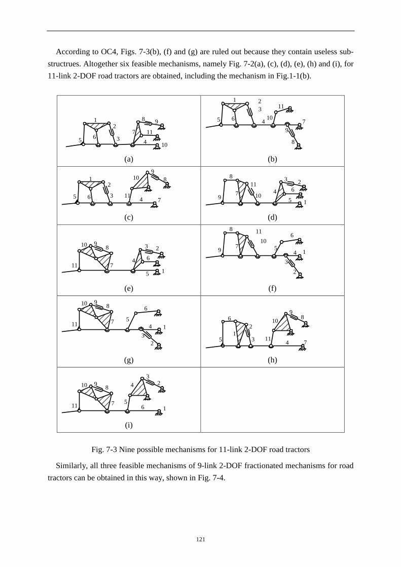
121
According to OC4, Figs. 7-3(b), (f) and (g) are ruled out because they contain useless sub-
structrues. Altogether six feasible mechanisms, namely Fig. 7-2(a), (c), (d), (e), (h) and (i), for
11-link 2-DOF road tractors are obtained, including the mechanism in Fig.1-1(b).
5
1
6
2
3
7
8 9
11
104
(a)
5
1
6
2
3
410
11
7
8
9
(b)
5
1
6
2
34
11
10 8
9
7
(c)
9
8
7
11
105
4
32
6
1
(d)
10 9
7
8
5
4
3 2
111
6
(e)
9
8
7
11
10
54
6
1
3
2
(f)
10 9
7
8
5
4
3
2
111
6
(g)
10
9
7
8
54
3
2
111
6
(h)
10 9
7
8
5
4
32
111 6
(i)
Fig. 7-3 Nine possible mechanisms for 11-link 2-DOF road tractors
Similarly, all three feasible mechanisms of 9-link 2-DOF fractionated mechanisms for road
tractors can be obtained in this way, shown in Fig. 7-4.

122
1
2
3
47
65
98
(a)
14
2
3
5
6
7
8
9
(b)
14
2
3
8
956
7
(c)
Fig. 7-4 Three feasible mechanisms for 9-link 2-DOF road tractors
If one wants to find all feasible mechanisms for this type of road tractor with non-
fractionated structures, the creative design can also be achieved with the same method.
The structural characteristics of the main mechanism are shown in Tab.7-4, where the
fractionated type is specified as SC1, the number of links as SC2 ,
the degrees of freedom as SC3, the nature of motion as SC4, the admissible types of joints as
SC5 and the number of basic loops as SC6.
Tab. 7-4 Structural characteristics for the non-fractionated main mechanism of a road tractor
No. Structural characteristics
SC1 The mechanism is non-fractionated.
SC2 The number of links is 9.
SC3 The mechanism has two DOFs.
SC4 The mechanism is confined to planar nature of motion, namely d equals three.
SC5 The type of joints is limited to revolute joints and prismatic joints only.
SC6 There are three basic loops.
The functional requirements for the main mechanism are shown in Tab.7-5. The
assortments of the frame and the output links are specified as FR1 and FR2. The relationships
of the output link and the big arm are specified as FR3 and FR4.

123
Tab. 7-5 The functional requirements for the main mechanism
No. Functional requirements
FR 1 The frame link is a multiple-pair link.
FR 2 The output link is a binary link.
FR 3 The output link cannot connect directly with the hydraulic cylinder.
FR 4 The big arm is connected with the frame link.
The other design constraints for the main mechanism are shown in Tab.7-6. The
mechanism is driven by two hydraulic cylinders, so there are two D-paths in the tological
graph of the mechanism, specified as OC1. Both the output link and the big arm are driven by
an individual hydraulic cylinder, so the D-paths cannot be placed in a basic loop, specified as
OC2.
6
5
17
4
3
2
8
9
43-2-3
1
2
3
45
67
8
9
1423-2-1
6
1
2
3
4
57
8
9
1423-2-1
1
2
3
4
56
78
9
1423-2-2
9
3
2
1
4
5
8
7
6
1423-2-6
5
6
7
84
3
2
1
9
1423-2-7
9
6
57
81
2
3
4
1423-2-7
Fig. 7-5 Seven feasible mechanisms for 9-link 2-DOF road tractors
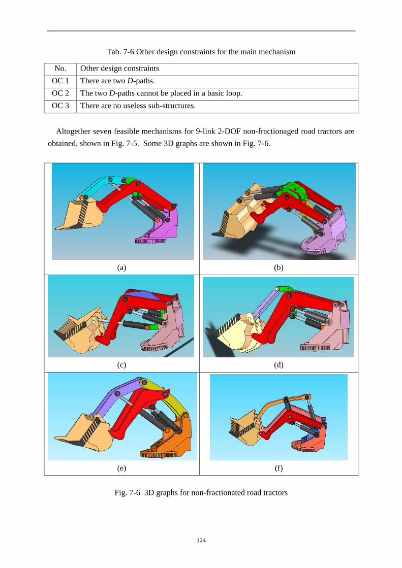
124
Tab. 7-6 Other design constraints for the main mechanism
No. Other design constraints
OC 1 There are two D-paths.
OC 2 The two D-paths cannot be placed in a basic loop.
OC 3 There are no useless sub-structures.
Altogether seven feasible mechanisms for 9-link 2-DOF non-fractionaged road tractors are
obtained, shown in Fig. 7-5. Some 3D graphs are shown in Fig. 7-6.
(a)
(b)
(c)
(d)
(e)
(f)
Fig. 7-6 3D graphs for non-fractionated road tractors

125
7.4 Creative design of 3-DOF hydraulic driven robots
3-DOF hydraulic driven mechanisms are widely used in various heavy-load robots, hydraulic
excavators, etc. All feasible 3-DOF hydraulic driven robots can also be obtained with this
creative design method.
The structural characteristics for 3-DOF hydraulic driven robots are shown in Tab.7-7,
where the fractionated type is specified as SC1, the number of links as SC2, the degrees of
freedom as SC3, the nature of motion as SC4, the admissible types of joints as SC5 and the
number of basic loops as SC6.
Tab. 7-7 The structural characteristics for 3-DOF hydraulic driven robots
No. Structural characteristics
SC1 The mechanism is non-fractionated.
SC2 The number of links is 12.
SC3 The mechanism has three DOFs.
SC4 The mechanism is confined to planar nature of motion, namely d equals three.
SC5 The type of joints is limited to revolute joints and prismatic joints only.
SC6 There are four basic loops.
The functional requirements for 3-DOF hydraulic driven robots are shown in Tab.7-8. The
assortments of the frame and the output links are specified as FR1 and FR2. The relationships
of the end effector and the base are specified as FR3.
Tab. 7-8 The functional requirements for 3-DOF hydraulic driven robots
No. Functional requirements
FR 1 The frame link is a ternary link.
FR 2 The output link is a binary link.
FR 3 The connectivity between the end effector and the base is three.
The other design constraints for the main mechanism are shown in Tab.7-9. The
mechanism is driven by three hydraulic cylinders, so there are three D-paths in the tological
graph of a mechanism, specified as OC1. The end effector and the base cannot be placed at a
basic loop, specified as OC2.
Tab. 7-9 The other design constraints for 3-DOF hydraulic driven robots
No. Other design constraints
OC 1 There are three D-paths.
OC 2 The the end effector and the base cannot be placed at a basic loop.
OC 3 There are no useless sub-structures.
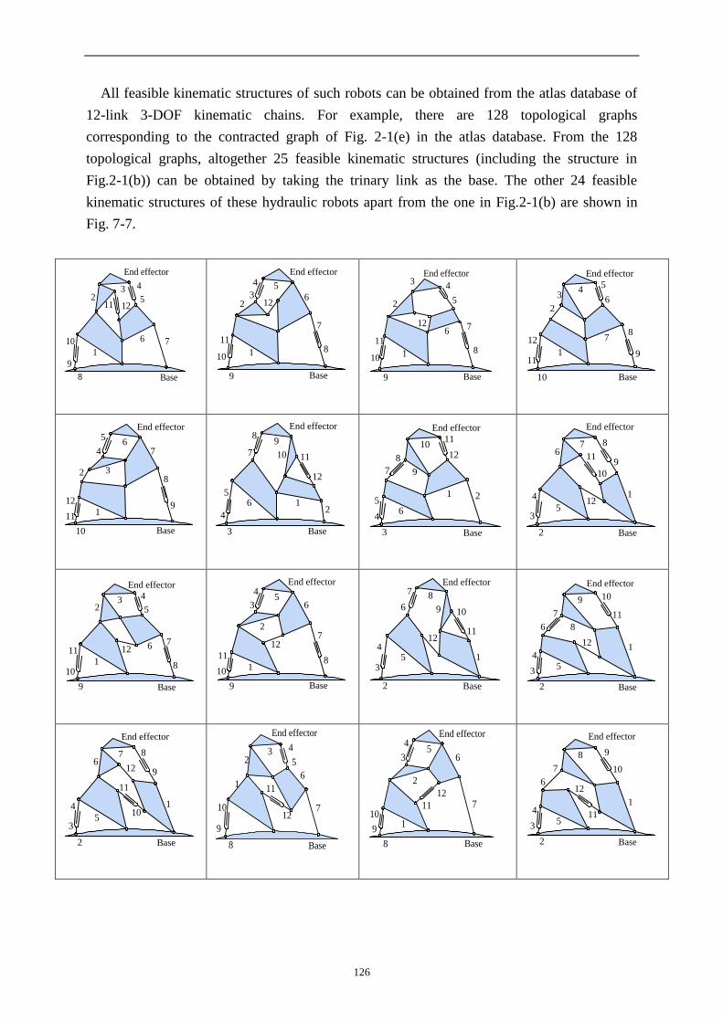
126
All feasible kinematic structures of such robots can be obtained from the atlas database of
12-link 3-DOF kinematic chains. For example, there are 128 topological graphs
corresponding to the contracted graph of Fig. 2-1(e) in the atlas database. From the 128
topological graphs, altogether 25 feasible kinematic structures (including the structure in
Fig.2-1(b)) can be obtained by taking the trinary link as the base. The other 24 feasible
kinematic structures of these hydraulic robots apart from the one in Fig.2-1(b) are shown in
Fig. 7-7.
Base
End effector
5
432
12
9
8
710
11
1
6
Base
54
32 12
9
8
7
10
11
1
6
End effector
Base
5
43
2
12
9
8
7
10
11
1
6
End effector
Base
54
3
2
12
9
87
10
111
6
End effector
Base
5
4
32
129
8
7
10
11 1
6
End effector
Base
5
4
3
2
12
98
7 10 11
16
End effector
Base
5
4
3
2
12
9
8
7
1011
1
6
End effector
Base
5
4
3
2
12
9
87
10
11
1
6
End effector
Base
5
432
12
9
8
7
10
111
6
End effector
Base
54
3
2
12
9
8
7
10
11
1
6
End effector
Base
54
3
2
12
9
87
10
11
1
6
End effector
Base
5
4
3
2
12
9
8
7
10
11
1
6
End effector
Base
5
4
3
2
12 9
87
10
11
1
6
End effector
Base
5
432
12
9
8
710
1116
End effector
Base
54
3
2
12
9
8
710
11
1
6
End effector
Base
5
4
3
2
12
98
7 10
11
1
6
End effector
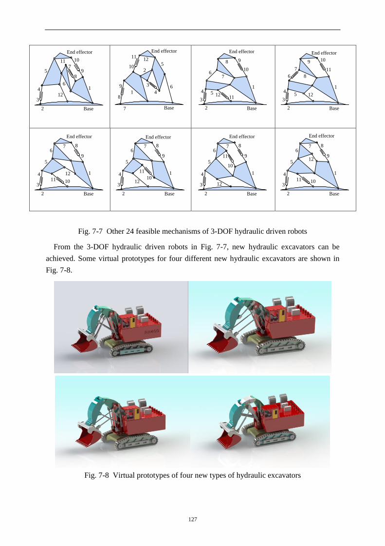
127
Base
5
4
3
2
12
98
7
1011
16
End effector
Base
5
4
3
2
12
9
8
7
10
11
16
End effector
Base
54
3
2
12
98
7
10
11
1
6
End effector
Base
54
3
2
12
9
8
7
10
11
1
6
End effector
Base
5
4
3
2
12
9
87
1011
1
6
End effector
Base
5
4
3
2
12
9
87
10
11 1
6
End effector
Base
5
4
3
2
12
9
87
10
11
1
6
End effector
Base
5
4
3
2
129
87
1011
1
6
End effector
Fig. 7-7 Other 24 feasible mechanisms of 3-DOF hydraulic driven robots
From the 3-DOF hydraulic driven robots in Fig. 7-7, new hydraulic excavators can be
achieved. Some virtual prototypes for four different new hydraulic excavators are shown in
Fig. 7-8.
Fig. 7-8 Virtual prototypes of four new types of hydraulic excavators

128
7.5 Creative design of forging manipulators
Forging manipulators are heavy industrial robots whose main task is to hold and manipulate
heavy forged pieces during the forging process. The forging manipulators can cooperate with
the forging press and are widely used in the forging industry. The use of forging manipulators
can boost the efficiency of the metal free forging and reduce energy consumption.
The gripper of a forging manipulator is connected to the gripper-support by a serially
articulated rotation joint. The function of the gripper of a forging manipulator is to realize six
essential motions, namely the lifting, pitching, lateral translation, yawing, horizontal
translation, and rolling, as shown in Fig. 1. The horizontal translation, lifting and pitching are
three main motions. The mechanism realizing the three main motions in a forging manipulator
is defined as the major-motion mechanism.The forging manipulator built by Dango &
Dienenthal [132] and its main kinematic mechanism are shown in Fig. 7-10 (a) and (b). SMS
Meer [133] also built a forging manipulator, shown in Fig. 7-11 (a) and (b).
z
ox
yyawing
lateral translation
horizontal translation
pitching
lifting
rolling
Fig. 7-9 Motion requirements of forging manipulators
(a) (b)
Fig. 7-10 The forging manipulator built by DDS and its main kinematic mechanism

129
(a) (b)
Fig. 7-11 The forging manipulator built by SMS Meer and its main kinematic mechanism
From the forging manipulators built by DDS and SMS Meer, we can see that the main
kinematic mechanism of a forging manipulator is a planar non-fractionated mechanism, which
has 12 links and three DOFs. The details of its structural characteristics are shown in Tab.7-10.
Tab. 7-10 The structural characteristics of the main kinematic mechanisms of forging
manipulators
No. Structural characteristics
SC1 The mechanism is non-fractionated.
SC2 The number of links is 12.
SC3 The mechanism has three DOFs.
SC4 The mechanism is confined to planar motion, thus d equals three.
SC5 The type of joints is limited to revolute joints and prismatic joints only.
SC6 There are four basic loops.
The functional requirements and other design constraints for the main kinematic
mechanisms of forging manipulators are shown in Tab. 7-11 and Tab. 7-12, respectively.
Tab. 7-11 The functional requirements for the main kinematic mechanisms of forging
manipulators
No. Functional requirements
FR 1 The frame link is a multiple-pair link.
FR 2 The gripper support is a binary or ternary link.
FR 3 The connectivity between the gripper support and the frame link is three.
Tab. 7-12 The other design constraints for the main kinematic mechanisms of forging
manipulators
No. Other design constraints
OC 1 There are three D-paths.
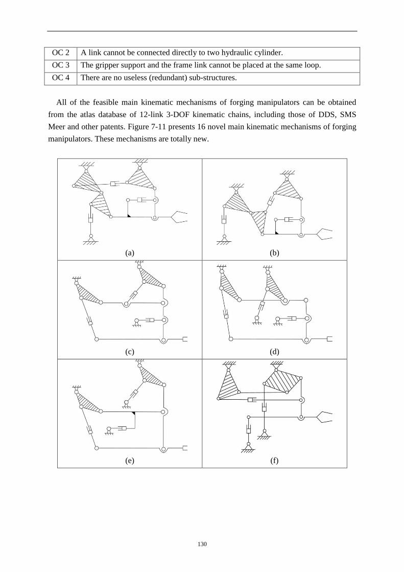
130
OC 2 A link cannot be connected directly to two hydraulic cylinder.
OC 3 The gripper support and the frame link cannot be placed at the same loop.
OC 4 There are no useless (redundant) sub-structures.
All of the feasible main kinematic mechanisms of forging manipulators can be obtained
from the atlas database of 12-link 3-DOF kinematic chains, including those of DDS, SMS
Meer and other patents. Figure 7-11 presents 16 novel main kinematic mechanisms of forging
manipulators. These mechanisms are totally new.
(a)
(b)
(c)
(d)
(e)
(f)

131
(g)
(h)
(i)
(j)
(k)
(l)
(m)
(n)

132
(o)
(p)
Fig. 7-11 16 novel main kinematic mechanisms of forging manipulators
From the main kinematic mechanisms in Fig. 7-11, new forging manipulators can be
obtained, shown in Fig. 7-12. The virtual prototypes of the new forging manipulators can also
be achieved, that for the forging manipulator in Fig. 7-12(a) is shown in Fig. 7-13.
(a)
(b)
(c)
(d)

133
(e)
(f)
(g)
(h)
Fig. 7-12 The mechanisms of new forging manipulators
Fig. 7-13 Virtual prototype for the new forging manipulator with the mechanism shown in
Fig. 7-12(a)
7.6 Summary
In this chapter, based on the classified atlas databases which can display topological structures
of mechanisms in graph forms, a systematic method is proposed for the creative design of
mechanisms. The main design processes with the method are computer-aided. For a specified
task, all the feasible mechanisms, regardless of simple or complex structures, can be obtained
with the method.
134
The creative design process is illustrated by the generation of all feasible structures for 2-
DOF road tractors, 3-DOF hydraulic driven robots and much more complex 6-DOF forging
manipulators. With this method, not only can the existing mechanisms already widely used be
obtained, but also a number of totally new mechanisms can be derived for the first time,
which is more meaningful. These examples verify the effectiveness of the method.

135
8 Conclusions
This thesis aims to find a systematic approach to aid the creative design of mechanisms.
Effective, automatic and human-machine interactive methods are proposed to synthesize
planar kinematic chains and mechanisms with simple and multiple joints. The classified atlas
databases are also established to classify, store and display the graphs for these mechanisms.
Based on the atlas database, the creation design of several kinds of mechanisms is conducted.
Some of the originalities of the thesis are as follows.
(1) The relationships of contracted graphs of planar non-fractionated kinematic chains as
well as their link assortment arrays are revealed. A fully-automatic method is proposed to
synthesize the contracted graphs of planar non-fractionated kinematic chains. The complete
families of non-fractionated contracted graphs and of valid contracted graphs with up to 19
links and all possible degrees of freedom are synthesized for the first time. The synthesis
results for the contracted graphs of non-fractionated kinematic chains with 2~6 basic loops are
the same as some existing results obtained with other methods, while the contracted graphs of
non-fractionated kinematic chains with seven and eight basic loops are totally new.
(2) An effective, fully-automatic and designer-friendly method is proposed to synthesize
the whole family of planar non-fractionated kinematic chains and mechanisms with specified
numbers of links and degrees of freedom. The classified atlas databases of planar non-
fractionated kinematic chains and mechanisms are also established. The effectiveness of the
method is proved by synthesis of planar non-fractionated kinematic chains and mechanisms
with up to 19 links (more i.e. substrantially than the 12 links in literature with graph-based
methods) for the first time as well as the establishment of their classified atlas databases.
(3) A fully-automatic approach is proposed to synthesize the whole family of planar
fractionated kinematic chains based on the combination of planar non-fractionated kinematic
chains and their atlas databases. The synthesis results of planar fractionated kinematic chains
with two, three and four basic loops are the same as widely acknowledged results in literature.
The whole family of planar fractionated kinematic chains with five, six and seven basic loops
are obtained for the first time, showing the effectiveness of the method.
(4) A fully-automatic method is proposed to synthesize the whole family of multiple joint
kinematic chains based on the new bicolor topological graph and the classified atlas databases
of simple joint kinematic chains. The whole family of multiple joint kinematic chains with up
to 16 links is synthesized for the first time, while with other methods only multiple joint
kinematic chains with no more than 10 links were synthesized. The classified atlas databases
of multiple joint kinematic chains with up to 16 links are also established.
(5) A creative design method is proposed based on the automatic structural synthesis and
classified atlas databases of kinematic chains with simple and multiple joints. For a specified
task, all the feasible mechanisms can be obtained from the topological graphs in the classified

136
atlas databases subject to specified design constraints. The creative design of road tractors,
hydraulic robots and forging manipulators is conducted as examples, from which a number of
novel mechanisms are obtained for the first time apart from the widely used ones, which
verifies the usefulness of the classified atlas database and the effectiveness of the creative
design method.
While the work has advanced the relevant research, it is likely and feasible to incorporate
more work to form a comprehensive theoretical system which would encompass in particular
the following two long-term goal
(1) automatic synthesis methods for other types of kinematic chains and mechanisms like
geared trains, parallel mechanisms, spatial polycyclic coupling mechanisms, mechanisms with
varying topology and metamorphic mechanisms, and others.
(2) automatic and unified methods for the kinematics, dynamics and performance index
analysis and optimization of various mechanisms under practical considerations.

137
References
[1] N.P. Suh, The Principles of Design, Oxford Univesity Press, New York, NY, 1990.
[2] D. Ullman, The Mechanical Design Process, McGraw, New York, NY, 1992.
[3] G. Pahl, W. Beitz, Engineering Design: A Systematic Approach, K.Wallace, Ed., Springer-Verlag,
London.
[4] H.S. Yan, Creative Design of Mechanical Devices, Springer-Verlag, Singapore, 1998.
[5] L.W. Tsai, Mechanism Design Enumeration of Kinematic Structures According to Function, CRC
Press, 2001.
[6] U. Döring, T. Brix, M. Reeßing, Application of computational kinematics in the digital
mechanism and gear library DMG-Lib, Mech. Mach. Theory 41 (8) (2006) 1003-1015.
[7] Z.Huang, Q.C. Li, H.F. Ding, Theory of Parallel Mechanisms, Springer, 2012.
[8] M. Gruebler, Allgemeine Eigenschaften der zwangläufigen ebenen kinematischen Ketten Part I,
Civilingenieur 29 (1883) 167–200; Part II, Verh. Ver.Bef. Gew. 64 (1885) 179–223.
[9] E. Pennestrì, N. P. Belfiore, On Crossley's contribution to the development of graph based
algorithms for the analysis of mechanisms and gear trains, Mech. Mach. Theory 89 (2015) 1003-
1015.
[10] F.R.E. Crossley, A contribution to Gruebler's theory in the number synthesis of planar
mechanisms, J. Eng.Indust., ASME Trans., Series B 86 (1964) 1–8.
[11] F.R.E. Crossley, On an unpublished work of Alt, J. Mechanisms 1 (1966) 165–170.
[12] B. Paul, A unified criterion for the degree of constraint of planar kinematic chains, J. Appl. Mech.,
ASME Trans.,Series E 27 (1960) 196–200.
[13] J. Volmer, Getriebetechnik, VEB Verlag Technik, Berlin,1971.
[14] F. Freudenstein, L.S. Woo, Kinematic structure of mechanisms, in: W.R. Spillers (Ed.), Basic
Questions of Design Theory, North Holland/American Elsevier, New York, (1974) 241–264.
[15] T.S. Mruthyunjaya, Kinematic structure of mechanisms revisited, Mech. Mach. Theory 38 (4)
(2003) 279-320.
[16] X. Kong, C. Gosselin, Type synthesis of parallel mechanisms, Springer, 2007.
[17] A.F. Al-Dweiri, F.T. Dweiri, O.M. Ashour, A novice-centered decision-support system for type
synthesis of function-generation mechanisms, Mech. Mach. Theory 45 (9) (2010) 1252-1268.
[18] F. Gao, Reflection on the current status and development strategy of mechanism research, Chinese
Journal of Mechanical Engineering 41(8) (2005) 3-17.
[19] H.J. Zou, F. Gao, Eds. Progress in Modern Mechanism (Vol. 2), Beijing: The High Education
Press, 2011.
[20] W. Fang, F. Freudenstein, The stratified representation of mechanisms, ASME J. Mech. Des.
112(3) (1990) 514–519.
[21] J.K. Shin, S. Krishnamurty, On identification and canonical numbering of pin jointed kinematic
chains, ASME J. Mech. Des. 116 (1994) 182-188.
[22] J.K. Shin, S. Krishnamurty, Development of a standard code for colored graphs and its application
to kinematic chains, ASME J. Mech. Des. 114(1) (1992) 189-196.
[23] T.H.Davies, F.R.E Crossley, Structural analysis of planar linkages by Franke’s condensed
notation, Journal of Mechanisms 1 (2) (1966) 171-183.
[24] R. Franke, Von Aufbau Der Getribe, Vol. 1, Beuthvertrieb, Berlin, 1943, Vol. 2, VDI, Düsseldorf,
1951.

138
[25] S.L.Haas, F.R.E. Crossley, Structural synthesis of a four-bit binary adding mechanism, J. Eng.
Indust., ASME Trans, Series B 91 (1969) 240–250.
[26] A.H. Soni, Structural analysis of two general constraint kinematic chains and their practical
application, ASME Journal of Engineering for Industry 93B (1) (1971) 231-238.
[27] F. Freudenstein, L. Dobrjanskyj, On a theory of type synthesis of mechanisms, in: Proceedings of
11th International Congress of Applied Mechanics, Springer, Berlin, (1964) 420–428.
[28] F.R.E. Crossley, The permutations of kinematic chains of eight members or less from the graph-
theoretic view point, in: Developments in Theoretical and Applied Mechanics, Pergamon Press,
Oxford 2 (1965) 467-486.
[29] N.L. Biggs , E.K. Lloyd, R.J. Wilson, Graph Theory, Clarendon Press, Oxford, 1976.
[30] L.S. Woo, Type synthesis of plane linkages, ASME Journal of Engineering for Industry 89B
(1967) 158-172.
[31] F. Freudenstein, The basic concepts of Polyas theory of enumeration with applications to
structural classification of mechanisms, J. Mechanisms 1 (1967) 275–290.
[32] F. Freudenstein, L.S. Woo, Kinematic structure of mechanisms, in: W.R. Spillers (Ed.), Basic
Questions of Design Theory, North Holland/American Elsevier, New York, (1974) 241–264.
[33] L. Dobrjanskyj, F. Freudenstein, Some applications of graph theory to the structural analysis of
mechanisms, ASME Journal of Engineering for Industry 89B (1967) 153-158.
[34] M. Huang, A.H. Soni, Application of linear and nonlinear graphs in structural synthesis of
kinematic chains, J. Eng. Indust., ASME Trans., Series B 95 (1973) 525–532.
[35] G. Kiper, D. Schian, The twelve-link Gruebler-type kinematic chains, Z. VDI 117 (1975) 283–288.
[36] G. Kiper, D. Schian, Sammlung der Grueblerschen kinematischen ketten mit bis zu zw lf
Gliedern, Z. VDI 118 (1976) 1066.
[37] T.S. Liu, C.C. Chou, Type synthesis of vehicle planar suspension mechanisms using graph theory,
115(3) (1993) 652-657.
[38] M.A. Pucheta, A. Cardona, An automated method for type synthesis of planar linkages based on a
constrained subgraph isomorphism detection, Multibody Syst. Dyn. 18(2) (2007) 233-258.
[39] M.A. Pucheta, A. Cardona, Synthesis of planar multiloop linkages starting from existing parts or
mechanisms: Enumeration and initial sizing, Mech. Based Des. Struct. Mach. 36(4) (2008) 364-
391.
[40] B.D. McKay, Practical graph isomorphism, Congressus Numerantium 30(1) (1981) 45–87.
[41] R.P. Sunkari , L.C. Schmidt , Structural synthesis of planar kinematic chains by adapting a
Mckay-type algorithm, Mech. Mach. Theory 41( 9) (2006) 1021-1030.
[42] Y. Lu, L. Ding, Autoderivation of topological graphs for type synthesis of planar 3DOF parallel
mechanisms, ASME Journal of Mechanism and Robotics 2(1) (2010) 0110021.
[43] Y. Lu, B.Y. Mao, et al, Derivation and isomorphism identification of valid topological graphs for
1-, 2-DOF planar closed mechanisms by characteristic strings, J of Mech Sci Technol 25(1) (2011)
255- 263.
[44] Y. Lu, B.Y. Mao, et al, Derivation of valid contracted graphs with pentagonal links plus
quaternary links or ternary links for closed mechanisms by arrays. Proc. IMechE Part C, J of
Mech Eng Sci 225(4) (2011) 1001-1013.
[45] Y. Lu, L. Ding, et al, Derivation of topological graphs of some planar 4-DOF redundant closed
mechanisms by contracted graphs and arrays, ASME Journal of Mechanism and Robotics 2(3)
(2010)(031011-1-10).
[46] H.S. Yan, C.H. Kang, Configuration synthesis of mechanisms with variable topologies, Mech.

139
Mach. Theory 44(5) (2009) 896-911.
[47] E.A. Butcher, C. Hartman, Efficient enumeration and hierarchical classification of planar simple-
jointed kinematic chains: Application to 12- and 14-bar single degree-of-freedom chains, Mech.
Mach. Theory 40 (9) (2005) 1030-1050.
[48] L.V. Assur, Investigation of plane hinged mechanisms with lower pairs from the point of view of
their structure and classification (in Russian): Part I, II, Bull. Petrograd Polytech. Inst. 20 (1913)
329-386; Bull. Petrograd Polytech. Inst. 21 (1914) 187-283 (vols. 21-23, 1914-1916).
[49] N.I. Manolescu, I. Ereceanu. P. Antonescu, The kinematic synthesis of mechanisms, Rev. Roum.
Sci. Tech. Ser.Mec. Appl. (1964) 341-363.
[50] N.I. Manolescu, A methodology for creative mechanism, Rev. Roum. Sci. Tech. Ser. Mec. Appl.
(1964)1263-1313.
[51] N.I. Manolescu, The synthesis of stable force-close graphs, Rev. Roum. Sci. Tech. Ser. Mec. Appl.
(1965) 999-1042.
[52] N.I. Manolescu, I. Tempea, The kinematic and control of a multi-finger, Rev. Roum. Sci. Tech.
Ser. Mec. Appl. (1967) 1117-1140.
[53] N.I. Manolescu, I.Tempea, A computerized method for the identification of planar pin-jointed of
incident degree, Rev. Roum. Sci. Tech. Ser. Mec. Appl. 12. (1967) 1251-1275.
[54] N.I. Manolescu, For a united point of view in the study of the structural analysis of kinematic
chains and mechanisms, Journal of Mechanisms 3 (3) (1968) 149–169.
[55] W.Q. Cao, J.K. Chu, Structural analysis and synthesis of Assur groups with multiple joints,
Chinese Journal of Mechanical Engineering 5(1) (1992) 24-27.
[56] J.K. Chu, W.Q. Cao, Systemics of Assur groups with multiple joints, Mech. Mach. Theory 33 (8)
(1998) 1127-1133.
[57] W.Q. Cao, The Analysis and Synthesis of Linkage Mechanisms (the 2th Edition), Science Press,
2002.
[58] C.R. Tischler, A.E. Samuel, K.H. Hunt, Kinematic chains for robot hands. I: Orderly number
synthesis, Mech. Mach. Theory 30 (1995) 1193–1215.
[59] C.R. Tischler, A.E. Samuel, H.H. Hunt, Kinematic chains for robot hands. II: Kinematic
constraints, classification, connectivity and actuation, Mech. Mach. Theory 30 (1995) 1217–1239.
[60] C. Alexandre, B. Christoph, H. Jürgen, A type synthesis method for hybrid robot structures, Mech.
Mach. Theory 43(8) (2008) 984-995.
[61] S.J. Li, J.S. Dai, Structural synthesis method of planar mechanisms using the Assur-group based
adjacency matrix, Journal of Mechanical Engineering 48(13) (2012) 13-18.
[62] E.R. Tuttle, S.W. Peterson, Symmetry group theory applied to kinematic chain enumeration, in:
Proceedings of the 10th Applied Mechanisms Conference, 1987, Vol. 2, Sec IV-B, New Orleans,
LA.
[63] E.R. Tuttle, S.W. Peterson, J.E. Titus, Further application of group theory to the enumeration and
structural analysis of basis kinematic chains, ASME Journal of Mechanisms, Transmissions and
Automation in Design 111 (1989) 494-497.
[64] E.R. Tuttle, S.W. Peterson, J.E. Titus, Enumeration of basis kinematic chains using the theory of
finite groups, ASME Journal of Mechanisms, Transmissions and Automation in Design 111 (1989)
498-503.
[65] E.R. Tuttle, Generation of planar kinematic chains, Mech. Mach. Theory 31 (1996) 729–748.
[66] H.S. Yan, Y.W. Hwang, Number synthesis of kinematic chains based on permutation groups,
Mathematical and Computer Modelling 13 (8) (1990) 29-42.
140
[67] H.S. Yan, A methodology for creative mechanism design, Mech. Mach. Theory 27 (3) (1992)
235-242.
[68] H.S. Yan, Y.M. Hwang, The specialization of mechanisms, Mech. Mach. Theory 26(6) (1991)
541–551.
[69] C.C. Hung, H.S. Yan, On the number of specialized mechanisms, 2008 Proceedings of the ASME
International Design Engineering Technical Conferences and Computers and Information in
Engineering Conference, DETC (2008) 603-609.
[70] H.S. Yan, C.C. Hung, Identifying and counting the number of mechanisms from kinematic chains
subject to design constraints, ASME J. Mech. Des. 128(5) (2006) 1177–1182.
[71] C.C. Hung, H.S. Yan, G.R. Pennock, A procedure to count the number of planar mechanisms
subject to design constraints from kinematic chains, Mech. Mach. Theory 43(6) ( 2008) 676–694.
[72] J.M. Hervé, Analyse structurelle des mécanismes par groupe des déplacements, Mech. Mach.
Theory 13(4) (1978) 437–450.
[73] Q.C. Li, Z. Huang, J.M. Hervé, Type synthesis of 3r2t 5-DOF parallel mechanisms using the Lie
group of displacements, IEEE Trans. Robot. Automat. 20(2) (2004)173–180.
[74] Q.C. Li, J.M. Herve, Parallel mechanisms with bifurcation of schoenflies motion, IEEE
Transactions on Robotics 25(1) (2009)158–164.
[75] C.C. Lee, J.M. Hervé, Translational parallel manipulators with doubly planar limbs, Mech. Mach.
Theory 24(4) ( 2006) 433–435.
[76] N.I. Manolescu, A method based on Baranov trusses and using graph theory to find the set of
planar jointed kinematic chains and mechanisms, Mech. Mach. Theory 8 (1) (1973) 3-22.
[77] T.S. Mruthyunjaya, Structural synthesis by transformation of binary chains, Mech. Mach. Theory
14 (4) (1979) 221-231.
[78] T.S. Mruthyunjaya, Structural synthesis by transformation of binary chains, Mech. Mach. Theory
14 (1979) 221–231.
[79] T.S. Mruthyunjaya, A computerized methodology for structural synthesis of kinematic chains:
Part 1-Formulation, Mech. Mach. Theory 19(6) (1984) 487-495.
[80] T.S. Mruthyunjaya, A computerized methodology for structural synthesis of kinematic chains:
Part 2-Application to several fully or partially known cases, Mech. Mach. Theory 19(6) (1984)
497-505.
[81] T.S. Mruthyunjaya, A computerized methodology for structural synthesis of kinematic chains:
Part 3-Application to new case of 10-link, three-freedom chains, Mech. Mach. Theory 19(6) (1984)
507-530.
[82] T.S. Mruthyunjaya, H. R. Balasubramanzan, In quest of a reliable and efficient computational test
for detection of isomorphism in kinematic chains, Mech. Mach. Theory 22(2) (1987) 131-140.
[83] W.J. Sohn, F. Freudenstein, An application of dual graphs to the automatic generation of the
kinematic structure of mechanisms, American Society of Mechanical Engineers (Paper) (1986)
86-DET-1.
[84] T.L. Yang, Topological characteristics and automatic generation of structural analysis and
synthesis of plane mechanisms, Part I: Theory, American Society of Mechanical Engineers,
Design Engineering Division (Publication) DE 15-1 (1988) 179-184.
[85] T.L. Yang, F.H. Yao, Topological characteristics and automatic generation of structural analysis
and synthesis of plane mechanisms, Part II: Application, American Society of Mechanical
Engineers, Design Engineering Division (Publication) DE 15-1 (1988) 185-190.
[86] T.L. Yang, Basic Theory of Mechanical Systems—Structures Kinematics Dynamics, Beijing:
141
Mechanical Press, 1995.
[87] A.C. Rao, Hamming number technique-I: Further applications, Mech. Mach. Theory 32 (4) (1997)
477-488.
[88] A.C. Rao, Hamming number technique-II: Generation of planar kinematic chains, Mech. Mach.
Theory 32 (4) (1997) 489-499.
[89] D. Varadaraju, Y. N. Kumar, A.C. Rao, A more direct method for structural synthesis of simple-
jointed planar kinematic chains, Mech. Synth. Anal. ASME 70 (1994) 507–516.
[90] K. Vijayananda, Computer-aided structural synthesis of linkages and epicyclic gear transmissions,
Ph.D. thesis, IISc, Bangalore, 1994.
[91] W.M. Hwang, Y.W. Hwang, Computer-aided structural synthesis of planar kinematic chains with
simple joints, Mech. Mach. Theory 27 (2) (1992) 189-199.
[92] H.S. Yan, C.H. Hsu, Contracted graphs of kinematic chains, Journal of Mathematical and
Computer Modelling, 10(9)(1988)681-695.
[93] C.H. Hsu, Simplification of multiple joints, Journal of the Chinese Society of Mechanical
Engineers, Transactions of the Chinese Institute of Engineers,12(4)(1991)357-363.
[94] C.H. Hsu, Enumeration of basic kinematic chains with simple and multiple joints, Journal of the
Franklin Institute 329(4) (1992) 775-789.
[95] C.H. Hsu, J.J. Hsu, An efficient methodology for the structural synthesis of geared dinematic
chains, Mech. Mach. Theory 32(8)(1997) 957-973.
[96] A.C. Rao, P.B. Deshmukh, Computer-aided structural synthesis of planar kinematic chains
obviating the test for isomorphism, Mech. Mach. Theory 36 (4) (2001) 489-506.
[97] Z.H. Lan, R. Du, Representation of topological changes in metamorphic mechanisms with
matrices of the same dimension, Trans, ASME J. Mech. Des. 130(7)(2008) 074501-1-4.
[98] J.S. Dai , J. R. Jones, Mobility in metamorphic mechanisms of foldable/erectable kinds,
Transactions of the ASME: Journal of Mechanical Design 121(3)(1999)375-382.
[99] L. Song, J. Yang, X.M. Zhang , W.Q. Cao, Spanning tree method of identifying isomorphism and
topological symmetry to planar kinematic chain with multiple joints, Chinese Journal of
Mechanical Engineering (English Edition) 14(1)(2001)27-31.
[100] L. Song, J. Yang, W.Q. Cao, Combination method of type synthesis for planar kinematic chains
with multiple joints, Chinese Journal of Mechanical Engineering 40(2)(2004)37-41.
[101] L. Song, Y. Huang, L. Cheng, Adjacent matrix method of identifying isomorphism to planar
kinematic chain with multiple joints and higher pairs, Chinese Journal of Mechanical Engineering
(English Edition) 19(4)(2006)605-609.
[102] W.H. Li, X.W. Zhang, H.M. Li, A method for structural synthesis of planar kinematic chains, in:
Proceedings of the 9th World Congress on the Theory of Machines and Mechanisms (1995)129–
133.
[103] P. Mitrouchev, Symbolic structural synthesis and a description method for planar kinematic
chains in robotics, Eur. J. Mech. A/Solids 20(2001) 777-794.
[104] J.J. Uicker, A. Raicu, A method for the identification and recognition of equivalence of kinematic
chains, Mech. Mach. Theory 10(5)(1975)375-383.
[105] H.S. Yan, A. S. Hall, Linkage characteristic polynomials: definitions, coefficients by inspection,
ASME J. Mech. Des. 103(3)(1981)578-584.
[106] T.S. Mruthyunjaya, H. R. Balasubramanzan, In quest of a reliable and efficient computational test
for detection of isomorphism in kinematic chains, Mech. Mach. Theory 22(2)(1987)131-140.
[107] P.R. He, W.J. Zhang, Q. Li, etc, A new method for detection of graph isomorphism based on the

142
quadratic form, ASME J. Mech. Des. 125(3)(2003)640-642.
[108] Z.Y. Chang, C. Zhang, Y.H. Yang, etc, A new method to mechanism kinematic chains
isomorphism identification, Mech. Mach. Theory 37(4)(2002)411-417.
[109] P.S. Rajesh, C.S. Linda, Reliability and efficiency of the existing spectral methods for
isomorphism detection, ASME J. Mech. Des. 128(6) (2006)1246-1252.
[110] W. Hwang, Y.Hwang, An algorithm for the detection of degenerate kinematic chains,
Mathematical and Computer Modelling 15(11)(1991)9-15.
[111] H. Lee, Y. Yoon, Detection of rigid structure in enumerating basic kinematic chains by sequential
removal of binary link string, JSME International Journal 35(4) (1992)647-651.
[112] C.H. Hsu , Y.C. Wu, Automatic detection of embedded structure in planetary gear trains, Journal
of Mechanical Design, Transactions of the ASME 119(2)(1997)315-318.
[113] H.F. Ding, Z. Huang, The establishment of the canonical perimeter topological graph of kinematic
chains and isomorphism identification, ASME J. Mech. Des. 129(9)(2007)915-923.
[114] H.F. Ding, Z. Huang, Isomorphism identification of graphs: Especially for the graphs of kinematic
chains, Mech, Mach. Theory 44(1)(2009)122-139.
[115] H.F. Ding, Z. Huang, D.J. Mu, Computer-aided structure decomposition theory of kinematic
chains and its applications, Mech. Mach. Theory 43(12)(2008) 1596-1609.
[116] H.F. Ding, Z. Huang, A unique representation of the kinematic chain and the atlas database,
Mech. Mach. Theory 42(6) (2007)637-651.
[117] H.F. Ding, Z. Huang, A new theory for the topological structure analysis of kinematic chains and
its applications, Mech. Mach. Theory 42(10)(2007)1264-1279.
[118] D.G. Olson, T.R. Thompson, D.R. Riley, et al, An algorithm for automatic sketching of planar
kinematic chains, ASME Journal of Mechanisms, Transmissions and Automation in Design 107
(1985) 106-111.
[119] N.P. Belfiore, E. Pennestri, Automatic sketching of planar kinematic chains, Mech. Mach. Theory
29 (1) (1994) 177-193.
[120] S. Mauskar, S. Krishnamurty, A loop configuration approach to automatic sketching of
mechanisms, Mech. Mach. Theory 31 (4) (1996) 423-437.
[121] C.F. Hsieh, Y.W. Hwang, H.S. Yan, Generation and sketching of generalized kinematic chains, In:
Proceedings of 2008 ASME DETC conference, Chicago, USA.
[122] M.A. Pucheta, N.E. Ulrich, Alberto Cardona, Combined graph layout algorithms for automated
sketching of kinematic chains, In: Proceedings of 2012 ASME DETC conference (paper
DETC2012-70665), Chicago, USA.
[123] F.G. Flores, A. Kecskeméthy, A. Pöttker, Workspace analysis and maximal force calculation of a
face-shovel excavator using kinematical transformers. Proceedings of the 12th World Congress in
Mechanism and Machine Science, Besancon, France, June 17-21, 2007.
[124] N.I. Manolescu, A unitary method for construction of the kinematic plane chains and plane
mechanisms with different degrees of mobility, Revue Roumaine des Sciences Techniques, Serie
de Mecanique Appliquee 9 (1964) 1263–1313.
[125] R. Simoni, A.P. Carboni, H. Simas, D. Martins, Enumeration of kinematic chains and mechanisms
review, 13th Word Congress in Mechanism and Machine Science, Guanajuato, México, 19-25,
June, 2011.
[126] R. Simoni, A.P. Carboni, D. Martins, Enumeration of kinematic chains and mechanisms,
Proceedings of The Institution of Mechanical Engineers, Part C: Journal of Mechanical
Engineering Science 223(4) (2009) 1017-1024.

143
[127] D. Martins, R. Simoni, A.P. Carboni, Fractionation in planar kinematic chains: reconciling
enumeration contradictions, Mech. Mach. Theory 45(11)(2010) 1628-1641.
[128] J.K. Chu, Y.H. Zou, P.F. He, A method for structural synthesis of planar simple and multiple joint
kinematic chains, International Mechanisms and Machine Science Conference, China, 2012.
[129] F. Freudenstein, E.R. Maki, The creation of mechanisms according to kinematic structure and
function, Environ. Plann. B(6) (1979)375–391.
[130] D.Z. Chen, W.M. Pai, A methodology for conceptual design of mechanisms by parsing design
specifications, ASME J. Mech. Des. 127(11)(2005)1039-1044.
[131] G. Pahl, W. Beitz, Engineering Design: A Systematic Approach, Springer Verlag, New York,
1999.
[132] Dango & Dienenthal Forging Manipulator, http://www.dds-gmbh.com.
[133] Rail Forging Manipulators, http://www.sms-meer.com/produkte.

144

145
List of publication during the doctoral study
[1] Huafeng Ding, Fengmao Hou, Andrés Kecskeméthy, Zhen Huang. Synthesis of a complete set of
contracted graphs for planar non-fractionated simple-jointed kinematic chains with all possible
DOFs. Mechanism and Machine Theory, 2011, 46(11):1588-1600.
[2] Huafeng Ding, Andrés Kecskeméthy, Zhen Huang (2011): Atlas database of 2-DOF kinematic
chains and its application to the creative design of mechanisms. ASME 2011 International Design
Engineering Technical Conference & Computer and Information in Engineering Conference,
August 28-31, 2011, Washington, DC, USA, DETC2011- 47264.
[3] Shuxian Xia, Huafeng Ding, Andrés Kecskeméthy (2011): Rigid subchain identification of multi-
loop kinematic chains with the method of kinematical transformers. Kolloquium Getriebetechnik,
September 07-09, 2011, Chemnitz, Germany.
[4] Huafeng Ding, Fengmao Hou, Andrés Kecskeméthy, Zhen Huang. Synthesis of the whole family
of planar 1-DOF kinematic chains and creation of their atlas databases. Mechanism and Machine
Theory, 2012, 47(1): 1-15.
[5] Huafeng Ding, Wenao Cao, Andrés Kecskeméthy, Zhen Huang, Complete atlas database of 2-
DOF kinematic chains and creative design of mechanisms, ASME Journal of Mechanical Design,
2012, 134(3): 0310061-03100610.
[6] Huafeng Ding, Peng Huang, Bin Zi, Andrés Kecskeméthy, Automatic synthesis of kinematic
structures of mechanisms and robots especially for those with complex structures, Applied
Mathematical Modelling, 2012, 36(12): 6122-6131.
[7] Shuxian Xia, Huafeng Ding, Andrés Kecskeméthy. A loop-based approach for rigid subchain
identification in general mechanisms. in:Jadran Lenarčič, Manfred Husty (Eds.), Latest Advances
in Robot Kinematics, 2012, Springer.
[8] Huafeng Ding, Weijuan Yang, Peng Huang, Li Ma, Andrés Kecskeméthy, Zhen Huang (2013):
Automatic synthesis of planar multiple joint kinematic chains. ASME 2013 International Design
Engineering Technical Conference & Computers and Information in Engineering Conference,
August 4-7, 2013, Portland, OREGON, USA, DETC2013-12915.
[9] Huafeng Ding, Bin Zi, Peng Huang, Andrés Kecskeméthy. The whole family of kinematic
structures for planar 2- and 3-DOF fractionated kinematic chains. Mechanism and Machine
Theory, 2013, 70: 74-90.
[10] Huafeng Ding, Peng Huang, Jingfang Liu, Andrés Kecskeméthy, Automatic structural synthesis
of the whole family of planar 3-DOF closed loop mechanisms. ASME Journal of Mechanisms and
Robotics, 2013, 5(4): 041006-1-10.
[11] Huafeng Ding, Weijuan Yang, Peng Huang, Andrés Kecskeméthy, Automatic structural synthesis
of planar multiple joint kinematic chains. ASME Journal of Mechanical Design, 2013, 135(9):
091007-1-12.

146

147
Acknowledgements
First of all, I would like to deliver my heartfelt gratitude to Prof. Andrés Kecskeméthy, to
whom I was indebted for much more than this thesis. I was luckily supervised for my doctoral
studies and hosted for my AvH research by him. He has guided me and inspired me with his
advanced research work and with his enlightening disussions and conversations with me.
Were it not for him, the materialization of the doctorate application would have been
impossible in the first place. But I was obliged to him for much more. He supported me for
my application for the AvH sholarship with his care, his encouragement, and his valuable
suggestions, all of which meant a lot and still means a lot to me. During my stay in Germany,
he was always kind and thoughtful, and his help extended beyond my research work there. A
busy professor as he is, he went as far as helping me to solve a few personal problems, such as
finding a living place, a family doctor and a kindergarten for my daughter. Back in China, that
invaluable experience of studying with him has always given me strength in my researches.
His appreciation and encouragement have always been an important source of support for me.
My gratitude also goes to Prof. Huang Zhen, my supervisor for the master’s and doctor’s
degree in China, and a life-long teacher to me. He has been supporting me for over 10 years,
from when I was an undergraduate till now. To me he is like a light in the dark. Each time I
achieved one goal and was about to think about the next, he would show up and suggest
another goal. He has been with me, watching me, encouraging me, and reminding me all
along the way. Each important step I took in the past was closely associated with him. He was
one who truly cares for the progress of mechanical research in China, truly cares for the
students, and truly derives joy from the achievements by his students. Though retired he still
keeps an eye on the international development of mechanisms and on my work, and offers
valuable suggestions when he considers it necessary.
I also thank my friends in Germany for their kindness and help with my research work or
with things in life. They are Prof. Müller, Ms. Xia Shuxian, Mr. Zi Bin, Mr.Wang Qiang, Mr.
Zhao Xingwei, and Mr. Yu Jie, to name just a few of them. Without them my academic stay
in Germany would not have been as pleasant as it was.
I am very grateful for my dear wife Yanqiao Zhao, who has loved me, and helped me in
both my life and work. I would also like to thank my charming daughter Xiaoduo Ding, who
has brought me much happiness. Last but not least, I would like to express my gratitude to my
parents, who have loved me and supported me for all these years.
Top Related