zzzzzzzzzzzzzzzzzzzzzzzzzzzz P roposa 1 [cor a Diao-ram o ...€¦ · ZZZZZZZZZ zzzzzzzz z Z zzzzzz...
8
zzzzzzzzzzzzzzzzzzzzzzzzzzzz ZZZZZZZ Z ZZZZZD Z zzzzz ZZZZZZ Z ZZZZAD Z zzzzzz ZZZZZ Z ZZZZAII Z zzzzzzz ZZZZ Z ZZCZAD Z ZZZZZZZZ ZZZ Z ZIIIZAC Z zzzzzzzzz zzzz z zzzzzz z zzzz zzzz ZZZZZ Z ZIZZZZ Z ZZZZZZZ ZZZZZZ Z ZIDZZZ Z zzzzzz ZZZZZZZ Z ZIDZZZ Z ZZZZZ ZZZZZZZZ Z ZIDZAZ Z ZZZZ ZZZZZZZZZ Z ZIIIZAC Z ZZZ zzzzzzzz z zzzzzz z zzzz ZZZZZZZ Z ZZZZZD Z ZZZZZ ZZZZZZ Z ZZZZAD Z ZZZZZZ ZZZZZ Z ZZZZAII Z ZZZZZZZ ZZZZ Z ZZCZAD Z ZZZZZZZZ ZZZ Z ZIIIZAC Z ZZZZZZZZZ zzzz z zzzzzz z zzzzzzzz ZZZZZ Z ZIZZZZ Z ZZZZZZZ ZZZZZZ Z ZIDZZZ Z ZZZZZZ ZZZZZZZ Z ZIDZZZ Z ZZZZZ ZZZZZZZZ Z ZIDZAZ Z ZZZZ ZZZZZZZZZ Z ZIIIZAC Z ZZZ zzzzzzzz z zzzzzz z zzzz ZZZZZZZ .Z ZZZZAD Z ZZZZZ ZZZZZZ ·z ZZCZAD Z ZZZZZZ ZZZZZ Z ZIIIZAC Z ZZZZZZZ zzzzzzzzzzzzzzzzzzzzzzzzzzzz P 1 [cor a Di ao-rammatic Language for Design roposa o Robert E. David · t 1 design as a process is a communication activity wherein the EnVIronmen a . 'd · h' . t' ously fiormulates records. and presents developmg 1 eas usmg ts destgner con mu ' · f d · uJ k tches working drawings and models. The success o the estgn vernac ar,s e , ' . . . . . 1 · d ds to a certain extent on the sophtsttcatiOn of the commumcatton so utton epen . . . . 1 d · h Is d o there is a significant lack ofsophtsttcatiOn m the too s use lD t e tran- too use ' 1 . 1 h Th' · · f'd between the initial verbal phases and the fina vtsua p ases. ts s1tton o 1 eas . . 'd h . poses a notational l anguage of d1agrammattc elements to p rovt e t e pape1 pro . . . 1 . b . d · designer with a tool that h1m to vtsua astc estgn . ideas at a high level of abstractiOn. elements ofth1s languag e e- sent a set of ideas that , in various combmat10ns, make up the baste entities of variousoproblems in environmental destgn. The general activity of applied in design professions has been trad1t10nally termed Sim.ply the design process." It consists of two major phases_: the .analytic and the synthetic phase. The analytic phase w1th defimtwn of . problem and expands into a hterature a nd solutions to similar problems. The mtent of th1s research effort 1s to produce what the architectural profession calls the a delineation of the objectives or requirements of the final solut10n. The medium of expression in the analytic phase is, for the most part, the designer's vernacular and thus is essentially verbal. The synthetic phase of the design process hopefully will produce a working drawing andfor scale-model description of an optimal solution to the design problem. The se working drawings are commonly preceded by several stages of"preliminary" drawings of varying degrees of completion which are, in turn, prececkd by many stages of"sketches." The '-.. medium of expression in the synth etic phase is, for the most part, scale drawings of varying degrees of crudeness and thus is essentially visual. 123 David: Diagrammatic Languagefor Design Visible lAnguaze, VI (Spring 1 972) , 123- 137· © 1972 , Visible lAn guage, cfo The Cleveland M useum of Art , Cleveland, Ohio USA 44 1 o6. Author's address : Kansas City Art Institute, Kansas City, Mo. 64 11 1.
Transcript of zzzzzzzzzzzzzzzzzzzzzzzzzzzz P roposa 1 [cor a Diao-ram o ...€¦ · ZZZZZZZZZ zzzzzzzz z Z zzzzzz...
zzzzzzzzzzzzzzzzzzzzzzzzzzzz ZZZZZZZ Z ZZZZZD Z zzzzz ZZZZZZ Z ZZZZAD Z zzzzzz ZZZZZ Z ZZZZAII Z zzzzzzz ZZZZ Z ZZCZAD Z ZZZZZZZZ ZZZ Z ZIIIZAC Z zzzzzzzzz zzzz z zzzzzz z zzzzzzzz ZZZZZ Z ZIZZZZ Z ZZZZZZZ ZZZZZZ Z ZIDZZZ Z zzzzzz ZZZZZZZ Z ZIDZZZ Z ZZZZZ ZZZZZZZZ Z ZIDZAZ Z ZZZZ ZZZZZZZZZ Z ZIIIZAC Z ZZZ zzzzzzzz z zzzzzz z zzzz ZZZZZZZ Z ZZZZZD Z ZZZZZ ZZZZZZ Z ZZZZAD Z ZZZZZZ ZZZZZ Z ZZZZAII Z ZZZZZZZ ZZZZ Z ZZCZAD Z ZZZZZZZZ ZZZ Z ZIIIZAC Z ZZZZZZZZZ zzzz z zzzzzz z zzzzzzzz ZZZZZ Z ZIZZZZ Z ZZZZZZZ ZZZZZZ Z ZIDZZZ Z ZZZZZZ ZZZZZZZ Z ZIDZZZ Z ZZZZZ ZZZZZZZZ Z ZIDZAZ Z ZZZZ ZZZZZZZZZ Z ZIIIZAC Z ZZZ zzzzzzzz z zzzzzz z zzzz ZZZZZZZ .Z ZZZZAD Z ZZZZZ ZZZZZZ ·z ZZCZAD Z ZZZZZZ ZZZZZ Z ZIIIZAC Z ZZZZZZZ zzzzzzzzzzzzzzzzzzzzzzzzzzzz
P 1 [cor a Diao-rammatic Language for Design roposa o
Robert E. David
· t 1 design as a process is a communication activity wherein the EnVIronmen a . 'd · h' . t' ously fiormulates records. and presents developmg 1 eas usmg ts destgner con mu ' · f d ·
uJ k tches working drawings and models. The success o the estgn vernac ar,s e , ' . . . . . 1
· d ds to a certain extent on the sophtsttcatiOn of the commumcatton so utton epen . . . . 1 d · h Is d o there is a significant lack ofsophtsttcatiOn m the too s use lD t e tran-
too use ' 1 . 1 h Th' · · f'd between the initial verbal phases and the fina vtsua p ases. ts s1tton o 1 eas . . 'd h . poses a notational language of d1agrammattc elements to provt e t e pape1 pro . . . 1. b . d ·
designer with a coromunicatio~ tool that ~er~.tts h1m to vtsua t~e astc estgn . ideas at a high level of abstractiOn. Th~ pn~ttve elements ofth1s language r~pt esent a set of ideas that, in various combmat10ns, r~currently make up the baste entities of variousoproblems in environmental destgn.
The general activity of applied ~~thodology in t~e envi~~nment.al design professions has been trad1t10nally termed Sim.ply the design process." It consists of two major phases_: the .analytic p~~se and the synthetic phase. The analytic phase begm~ w1th ~ defimtwn of th~ . problem and expands into a searc~ ofpertme~t hterature and ~x1stmg solutions to similar problems. The mtent ofth1s research effort 1s to produce what the architectural profession calls the "program~" a delineation of the objectives or requirements of the final solut10n. The medium of expression in the analytic phase is, for the most part, the designer's vernacular and thus is essentially verbal. The synthetic phase of the design process hopefully will produce a working drawing andfor scale-model description of an optimal solution to the design problem. These working drawings are commonly preceded by several stages of"preliminary" drawings of varying degrees of completion which are, in turn, prececkd by many stages of"sketches." The
'-.. medium of expression in the synthetic phase is, for the most part, scale drawings of varying degrees of crudeness and thus is essentially visual.
123 David: Diagrammatic Languagefor Design
Visible lAnguaze, VI (Spring 1972), 123- 137· © 1972, Visible lAnguage, cfo The C leveland M useum of Art , Cleveland, Ohio USA 44 1o6. Author's address : Kansas City Art Institute, Kansas City, Mo. 64 11 1.
This brings us to that stage of the design process which can be considered the middle zone of the process, where the verbal information of the analytic phase is evolved into the visual information of the synthetic phase. This transformation from verbal to visual information is characterized by series after series of sketchy expressions best described as "doodles." If we consider design as a communication activity, these doodles-their verbal predecessors and their visual successors- are tools of communication which the designer uses to continuously record developing ideas. In the case of the single designer working on a particular design problem, these records are maintained so that ideas may be communicated accurately back to the designer who originally recorded them. In the case of a team of designers working on a common problem, the records serve as conversational aids (visual and verbal) among the designers involved.
Conceivably, the sophistication of the design solution depends on the sophistication of the communication tools used. The tools in current use in the initial verbal and the final visual stages of the design process are reasonably well developed, i.e., the relevant vernacular and the working-drawing systems. H owever, the efficient handling of ideas generated as doodles is often difficult for a single designer because of his lack of recall, and proves to be impossible for a team of designers since each member of the team will have a different doodle "style." Actually, collaboration a t this stage of the design process is most likely not even considered. It follows, then, that there exists a need for a common language or notation system which would allow design ideas to be expressed and recorded in a consistent way. My interest in a diagrammatic language for design stems from involvement with decomposition computer programs for the analysis of design-problem structure and the use of constructive diagrams as part of this design methodology.! It is the contention of my thesis that there exists a set of diagrammatic elements which designers subconsciously use as part of their thought patterns which can be identified and formalized into a grammatical structure as a diagrammatic language for design. Research to date has been concerned with the following five stages:
I. Design methods and the design process in general. 2 . Diagram systems in current use in other disciplines. 3· Artificial languages and their compilers.
124 Visible Language: VI 2 Spring 1972
4· Identification of the elements of the design language and the subsequent grammatical structure.
5· Delineation of possible visual forms of the notation elements.
The next stage of the project will be:
6. Experiments in the use of the design language.
Full development of the language will be an evolutionary process resulting from its use. This paper, therefore, constitutes a preliminary report on a continuing project and is presented at this time to draw comments and criticism from designers and educators.
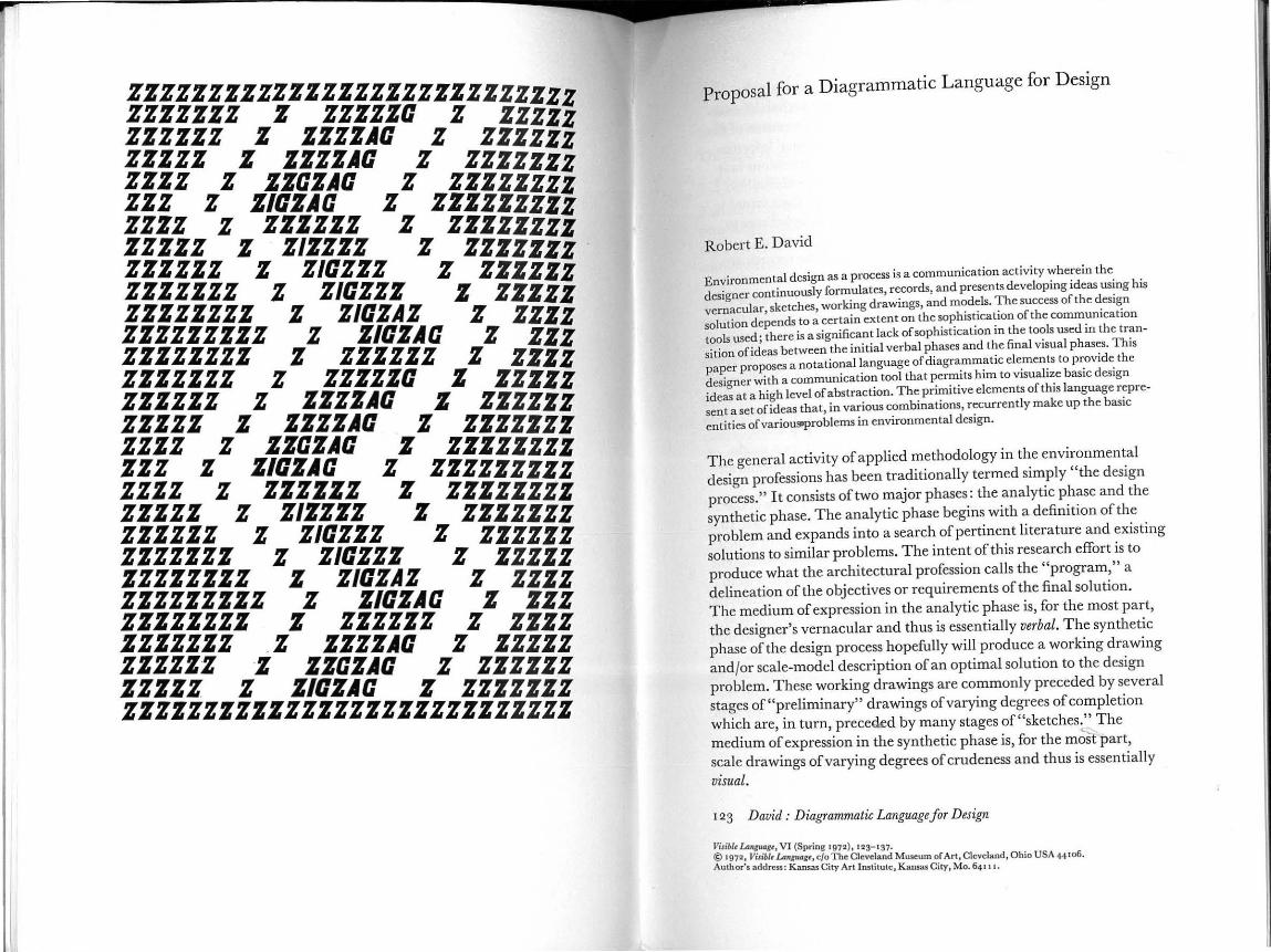
The Design Process It may be helpful at this point to look at some conceptual models of the design process in order to see where tlus diagrammatic language could be used. Figure I shows a very simplistic and familiar conception of the design process. The starting point is the definition of the problem; the endpoint, its solution. With respect to the discussion above, the area of divergence is essentially verbal and the area of convergence is• essentially visual. The area of overlap is the realm of the diagrams which supports the transition from verbal to visual.
Figure 1. Fan model of the d esign process.
definition of
the problem
divergence o f the analysis
convergence of the synthesis
solution to
the problem
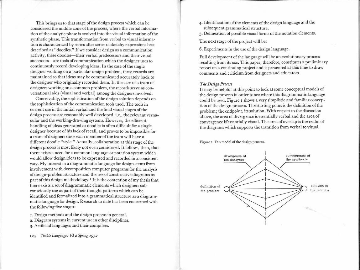
Noise
Encode Transmit Channel Receive Decode Evaluate
I 0 Convert Operation Reconstruc t
Input Process Output Evaluate
Method
Figure 2. Shannon and Weaver model of communication.
Figure 2 is a more complex model adapted from Shanon and Weaver's model ofcommunication.2 It can be considered in two ways: first, as an overall model of the design process in the sense of a problem definition (input), designer activity (process), and solution (output); second, as a model to be duplicated end-to-end as many times as there are identifiable stages of communication activities in the design process. For instance, the designer may "encode" thought and transmit via a "channel" of a sketch on paper to be "received" by a design partner or consultant or himself at a later time. "Noise" could be anything that would in any way deteriorate the quality of the intended message, from wrinkling the paper to the designer's lack of talent as a draftsman. R elative to diagrams as a communication activity we must consider such questions as: What is the encoding and transmitting process? What kind of channel is used? What is the receiving and decoding process? What kind of"noise" will be present during the process? How is the result evaluated? For the sake of simplicity the discussion will be limited to a handwritten notational system using suitable two-dimensional surfaces as media.
r26 VisibleLanguage: VI2Spring r972
~
~ !! 0
~ > . . . E E
~ "' . e ! ~ e -;
~ c ~
6 ~ 8' . g e 'i
l E 0 "' .. ~ 0 8' ,. ~ 8
l ~ a "8 8' e ~ :! g' E ~ ... c ~ i ::0 ~
§ :;; . ~ 0 -;;
~ E £ v 0
1 5 0 ::;; ~ "' "' .3 "' Q u
~ Time )
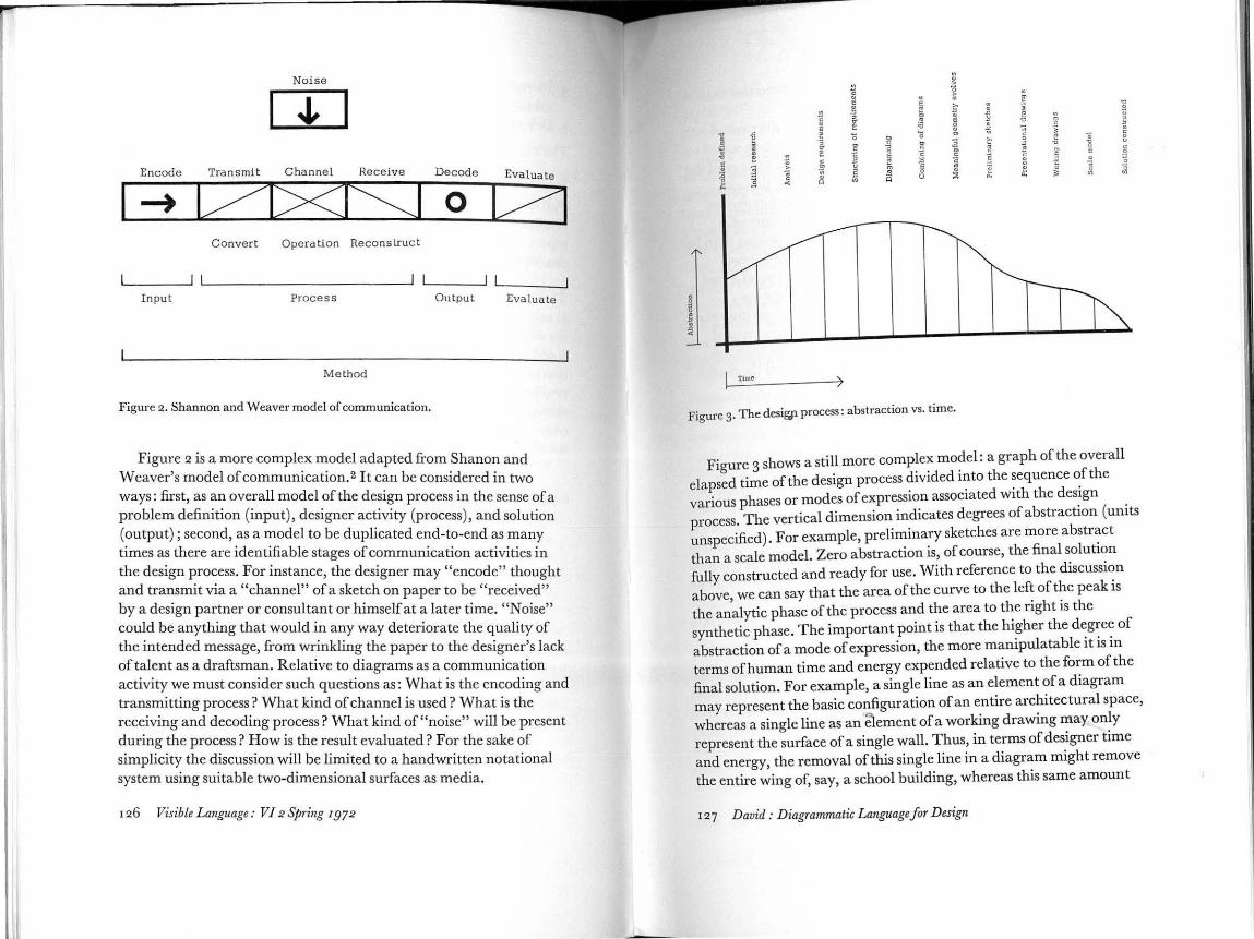
Figure 3. The desigp process: abstraction vs. time.
Figure 3 shows a still more comp~e~ mo?el: a graph of the overall elapsed time of the design process drvrded mto the ~equence ~fthe
· phases or modes of expression associated wrth the desrgn vanous . ( . process. The vertical dimension indicates degrees of abstract10n umts unspecified). For example, preliminary sketches are more abstr~ct
th a scale model. Zero abstraction is, of course, the final solut10n an h d' .
fully constructed and ready for use. With reference tot e rscussr~n above we can say that the area of the curve to the left of the peak rs the a~alytic phase of the process and the area to tl~e right is the synthetic phase. The important point is that the hi~her the d~g~e~ of abstraction of a mode of expression, the more mampulatable rt rs m terms of human time and energy expended relative to the form of the final solution. For example, a single line as an element of a diagram may represent the basic configuration of an entire architectural space, whereas a single line as an ·element of a working drawing x:ray on~y represent the surface of a single wall. Thus, in terms of desrgner trme and energy, the removal of this single line in a diagram might remove the entire wing of, say, a school building, whereas this same amount
127 David : Diagrammatic Languagefor Design
ofline removed from a working drawing might 0 1 . . . n ymean the removal of a smgle partition.
The reason for the different modes of expression for th . t f h d . . e vanous
s ages o t e esign process Is that each of these m d . b . d h o es Is est SUited
rec~r t e type of human thought being generated at that sta e to design process. a Herbert Simon refers to the elements of thou gh of the (parameters of memory) as "chunks." The h · d g t h uman mm generates
t ese chunks at reasonably constant intervals 4 If the t f h k f h . . · na ure o a c un o t ought Is different at one stage of the d .
h esign process than at anot er, the mode of expression (notation) used to record these chunks as they are generated must be capable ofreco d.
. . r mg at a rate commensurate With mterarrival time of the chunks. If the lag between chunk speed and notation speed becomes great an . ch k b r. . ' Important un may e lOrgotten before It can be notated Ad' . 1 . · Iagrammauc ang~age must provide the notation system that can cope with the
relational type of thought produced at this middle zone ofth d . process. 5 e esign
Diagrams and Language Systems
If ':e ar~ to devise a diagrammatic language and notation system for design, It would seem appropriate to survey similar d' · . . . Iagrammatic s~stem~ mother disciplines. Unfortunately, space does not permit a discussiOn of any of these here.
music notation6 L abanotation-dance notation 7 Motation- language of motions sequence experience notation 9
symbolic logic electronic schematics flowcharting of computer programs Therbligs-industrial process notationio architectural working drawings proofreading notationll PERT charts- scheduling networksiz Blissymbolics-visual languageis a Ui-language of space14
Proxemics- human interaction behavior notationi5
I 28 Visible Language : VI 2 Spring 1972
Kinesics- human movement notationi6
alphabet17
graph theory18
All of the above are visual systems containing a limited number of mbols which in various combinations and formats are capable of
describing a limitless number ofsituations_.19 In a~dition t~ the fi_eld of visual communication, traditionally associated with graphic design, 20
there is new interest in the use of visual languages as design tools. 21
The more firmly established world of non-visual linguistics22 functions with a few elements saying everything there is to say. Basic English reduces to Boo the number of English words necessary for conversation.zs Along with new inter-disciplinary research in environmental design there is interest in formulating a set of environmental descriptors for an agreement on terms in speaking about natural and manmade environment. 24
Diagrams as a Language System in Design The design proc<:l'!ls is an evolutionary progression; an idea is refined continuously until the resulting form satisfies the initial objectives. It is a process that proceeds from the general to the specific and from the abstract to the real. It is a process ofleveling and sharpening. 25 Once the analytic phase of the process is complete and the design objectives defined, the diagrammatic language will be employed to set down in a presentational visual way (as opposed to the sequential verbal methods of the analytic phase) the desirable relationships between the conceptual components. These relationships will evolve into ever more specific relationships that are defined by type and degree. The diagrammatic language must be both visual to show relationships, and mathematical to show degree of relationship. 26
Primitives and Grammar of a Design Language Since the initial diagrams in the design process would express the desirable relationships specified in the design requirements, it seemed logical that the place to beg·in a search for the basic elements, or primitives, of the design language would be among available collections of design requirements by various designers for particular problems. Consider the following three design requirements which are relevant to three different design problems:
129 David: Diagrammatic Languagefor Design

I. Urban mass transportation system: any pollution created by the transporation system must be contained and not be allowed to enter the environment external to the transit system.
2. Elementary educational facility: distraction factors external to an academic setting (such as a classroom) must be controlled so as to not disturb the students' concentration.
3· R esidence: children in their play activities should not be subject to contact with vehicular traffic.
The notion to be abstracted from these three requirements is a common one: "protection." Protection is the desirable relationship that should exist between the pairs of parties named in each of the three requirements.
On a similar basis, the accumulated design requirements of seven different documented environmental design problems were searched. The average number of requirements per problem was approximately IOO; approximately 200 notions were abstracted from these 700 requirements. Some notions occurred only once or twice, whereas notions such as "protection," "proximity," "access," and "control" occurred IO to 30 times each. The distribution was not tabulated in this initial search. Redundant notions (such as "control" and "supervision") were eliminated until approximately IOO notions remained. A positive or negative relationship was identified between every possible pair, and a decomposition computer program27 was used to identify subsets ofhighly interrelated notions. Analysis of the subsets revealed further synonymous ideas which were eliminated to produce a list of so notions (opposite), which may be considered as an attempt to see what the primitives of the design language might be.
These so primitives were, in turn, processed through the decomposition program and simplified further by observation and experiment to produce the structure shown in Figure 4· An initial attempt at defining the visual elements of the language is shown in Figures, where symbols and mnemonics have been substituted for the words in the structure of Figure 4·
The structure of this "grammar" proceeds downward from the general to the more specific. This is analogous to the leveling and sharpening nature of the design process. This structure is in need of
I go Visible Language: VI 2 Spring 1972
-1. adjacency 2. barrier-access g. behavior setting 4· boundary 5· communication channel 6. comparison 7. compliance 8. conceptual g. content
10. context 1 1. control 12.dependency I g. disipation 14.dynamic 1 5· enclosure 16. enter-leave J7. explicit
1 8. facility I g. feedback 20. format 21. gate
g5. position g6. privacy g7. process g8. property
22. generate-terminate gg. protection 2g. guidance 40. proximity 24. implicit 41. queue 25. information 42. relation 26. input-output 4g. replace 27. media 44· seize-release 28. mobile-stabile 45· sequence 29. motion (speed) 46. similarity go. negative-positive g1. parts g2. people gg. physical g4. point of contact
47· static 48. tool 49· supervision 50. vehicle
further refinemont, but it will provide a reasonable vehicle for illustrating the manner in which it might be used.
Application As an illustration, let us consider the design of the architectural students' academic work station-the studio. For the sake of simplicity let us consider two of the many design requirements which might be produced by the analytic phase of the design process:
I. Security from theft. The typical design school layout must permit continuous student access to the student studio areas. This open situation also permits access by strangers whose intention might be theft of the students' work tools.
2. Studio teaching routine. I nstructors typically come to the student studios for individual consultation with each student. However, there is often need of group discussion between faculty and students in the studio intermittent-with individual consultation.
Consider the structure in Figures and keep in mind that it will be used in top-to-bottom process. Beginning with Requirement r, we have a group offour stud ent work stations. These are entities which
1 g1 David : Diagrammatic Language for Design

r e i.ILIII'n
A conc\I!IIIMI l)hY= •c.al
depenlkonc:y pi'QIOII;IIotl po:utlon
M 1\ 1\ q,ud.,r.ncC' SII P'(!I'Vallon pnv.K"y rt~plo~ce sl•ll·uHy JII'OX••Ity PGinl of
l..,ttU!f n('9.lllV\l· .ldJiiCCncy enciC.tW""C pollia~
Figure 4· Grammar semi-lattice.
-R-
A 6 c p
pn)CitU
COMJIIIu.I\ICAIIIIn circulation
lnput·wtput U!IU•rctiGiiSct dtUI~t!On lctc:dbact cnler•lee\111 ~.-.ollt:'CI IIlft
tnlorawtlon CJl!I'IOt<liiO• c..-11111!\ICOIU)n U1mllnAict
chonrHt\ If>~ IA
CT
PR •
,,.(\ lorii.JoH 1.-ulwv•'-' 1(1111"9 l• calily
q\lf!\lf:
/\M ..ot1o11. s eq11..::nce vehicle a,.ce•plece b arrier taoblle· St4ble poOfiiO onc:I01111e 111~ vetudtc lilclllly 1101'.-QO
t.wndu y
·~·
PP
1\ D s
/\)\ DP A 1-H> ... CttH -\ ~ 0 [J
M/\1\ M\/\M '"'+ A (Q) ~ n= n· j_ I/o u,.... ~ ooo: -~ ~ n k. -
+ - II" !::) -@~ .llL .&' J.. c .......... -c -- w J-.....j n · 0 u
-\1).
Figure 5· Grammar semi-lattice with symbols. ..,...... ~
~
0 0 0 0 6A
0" D-~~A o-"'"/ 0
/r-6C
60
7A
7B
7C
8
~ ,ro ~ \
Q",,~"A' 0 ~ f·
X/ tO
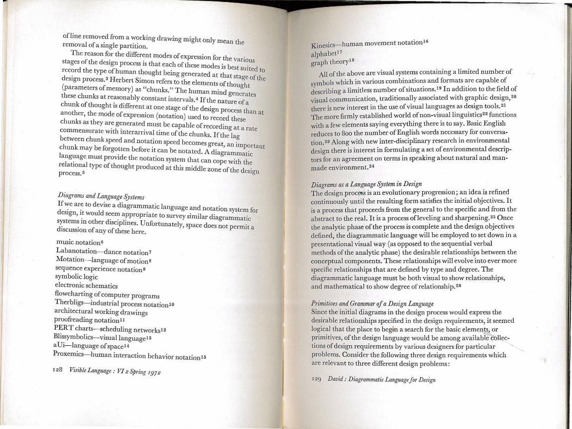
are identifiable by their property which is both dynamic and static as a behavior setting. Let us place these in a behavior setting drawn as an enclosure (Figure 6A). In Figure 6B we add another entity whose property is dynamic as a person and is considered to be a thief. This person has a certain relation "R" with each behavior setting, and the desirable relation is protection (Figure 6C) which can be accomplished by the addition of an additional enclosure (Figure 6D) about each behavior setting.
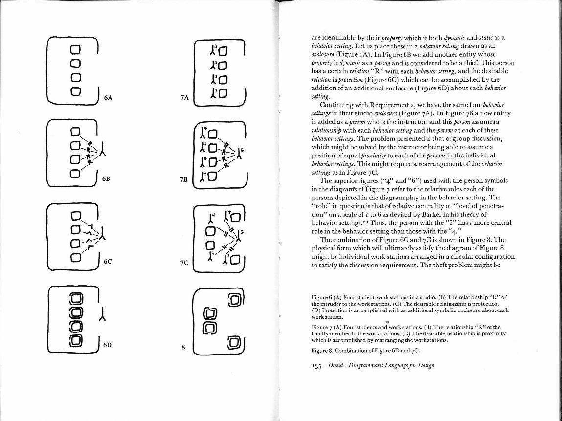
Continuing with Requirement 2, we have the same four behavior settings in their studio enclosure (Figure 7A). In Figure 7B a new entity is added as a person who is the instructor, and this person assumes a relationship with each behavior setting and the person at each of these behavior settings. The problem presented is that of group discussion, which might be solved by the instructor being able to assume a position of equal proximity to each of the persons in the individual behavior settings. This might require a rearrangement of the behavior settings as in Figure 7C.
The superior figures ("4" and "6") used with the person symbols in the diagra~ ofFigure 7 refer to the relative roles each of the persons depicted in the diagram play in the behavior setting. The "role" in question is that of relative centrality or "level of penetration" on a scale of 1 to 6 as devised by Barker in his theory of behavior settings.2s Thus, the person with the "6" has a more central role in the behavior setting than those with the "4."
The combination of Figure 6C and 7C is shown in Figure 8. The physical form which will ultimately satisfy the diagram of Figure 8 might be individual work stations arranged in a circular configuration to satisfy the discussion requirement. The theft problem might be
Figure 6 (A) Four student-work stations in a studio. (B) The relationship "R" of the intruder to the work stations. (C) The desirable relationship is protection. (D) Protection is accomplished with an additional symbolic enclosure about each work station. .., Figure 7 (A) Four students and work stations. (B) The relationship "R" of the faculty member to the work stations. (C) The desirable relationship is proximity which is accomplished by rearranging the work stations.
Figure 8. Combination of Figure 6D and 7C.
135 David: Diagrammatic Language for Design
solved by the use of a roll-top structure which could cover the entire work surface in one easy operation.
Conclusion The example above was, of course, overly simplified; many more design requirements would have come into play in the normal design situation and the diagram would have become quite complex. However, the elements for a basic theory of diagrammatic language are present. The grammatical structure as presented here needs to be tested; the visual elements have to be refined, and numerical notational elements will have to be employed as exponents of the basic visual primitives. The design requirements themselves will, no doubt, have to be written in a special format to make their translation into diagrams as efficient as possible. The next stage of this research effort will be experiments in the use of the language, carried out both in academic and professional environments. The form of the language will undoubtedly change in response to these experiments. Its ultimate efficient use will require, as with any language system, that the language be learned.
1. Serge Chermayeff & Christopher Alexander. Community and Privacy (New York: Doubleday, I 963); Christopher Alexander. Notes on the Synthesis of Form (Cambridge: Harvard, I964). 2. Claude Shannon & Warren Weaver. The Mathematical Theory of Communication (Urbana: Universityofillinois, I949). 3· Charles Rusch & Stuart Silverstone. "The Medium Is Not the Solution "AlA Journal (December, I967). ' 4· Herbert Simon. TheSciencesoftlwArtificial (Cambridge: M.I.T., 1969). 5· Christopher Alexander. "From a Set of Forces to a Form," The Man Made Object (Gyorgy K epes, editor), (New York: Braziller, 1966). 6. Gardner Read. Music Notation (Boston: Allen and Bacon, 1g6g). 7· Ann Hutchinson. Labanotation (New York: New Directions, 1954). 8. Lawrence Halprin. "Motation," Progressive Architecture (July, 1965). g. Philip Thiel. "A Sequence-Experience Notation," Town Planning Review (April, 1961); Donald Appelyard, Kevin Lynch, &John Myer. The View from the Road (Cambridge: M.I.T., 1964) . 1 o. American Society of Mechanical Engineering. Operation and Flow Process Charts (New York: A.S.M.E. Standard 101). I 1. Random House Dictionary of the English Language (New York: Random House, lg68). 12. Federal Electric Corporation. PERT (New York: Wiley, 1963); Mel Levinson. PERT for Designers (Chicago: Illinois Institute of T echnology, 1968).
136 Visible Language : VI 2 Spring r972
13. C:har~es Bliss. Semantography (Blissymbolics) (Sydney, Australia: Semantography PubhcatJons, Ig66). 14. John Weilgart. aUi: The Language of Space (Decorah, Iowa: Cosmic Communication Company, 1962) . I 5· Edward T. H all. "A System ofNotation for Proximic Behavior," American Anthropologist (October, 1963). 16. Raymond Birdwhistell. Introduction to Kinesics (Louisville, Kent: University of Louisville, 1952). 17. David Diringer & Reinhold Regensburger. The Alphabet: A Key to the History of Atfanl.:-ind (New York: Funk and Wagnalls, I97I). I8. Oystein Ore. Graphs and their Uses (New York: Random House, 1963). 19. Alvin Arnell. Standard Graphical Symbols (New York: McGraw-Hill, I 963); Leonard Bernstein. The Infinite Variety qf lvfusic (New York: Simon and Schuster, 1966) ; Frank Heacock. Graphical Solutions of Technical Problems (Princeton: Princeton University). 20. Paul Klee. The Thinking Eye (New York : Wittenborn, I961 ) ; Arthur Lockwood. Diagrams (New York: Watson-Guptil, 1969) ; Emil Ruder. Typography: Manual for Design (New York: Hastings House, 1968); Anton Stankowsky. Graphical Presentation of Invisible Processes (New York: Hastings House, Ig66). 21. Constance Perin. With Man in M ind (Cambridge: M.I.T., I970). 22. Francis Dineen. An Introduction to General Linguistics (New York: Holt, Rinehart and Winston, I967). 23.JuliaJohnsen. Basic English (Bronx, N .Y.: H. W. Wilson Company, I944); Charles Ogden. Br;sic English (London: Paul, Trench, Trubner, 1933). 24.Joyce Kasmar. "The Development of a Usable Lexicon of Environmental Descriptors," Environment and Behavior (September, 1970 ). 25. Charles Rusch. "On the Use of Leveling and Sharpening as an Analytic Tool in the Study of Artistic Behavior," Proceedings (Washington, D.C. : American Psychological Association, I g69). 26. Christopher Alexander. Ten-Tear Program for Research on Environmental Design (Berkeley: University of California, 1964). 27. Charles Owen. An Algorithm for the Decomposition qf Non-Directed Graphs (Chicago : lllinois Institute of Technology, 1968) . 28. Roger Barker. Ecological Psychology (Stanford: Stanford University, I968).
Additional Rifermces Christopher Alexander, Sara Ishikawa & Murray Silverstein. A Pattern Language which Generates Multi-Service Centers (Berkeley: Center for Environmental Structure, 1968). D. C. Engelhart. Augmenting Human Intellect (Stanford: Stanford Research Institute, 1962). IBM. General Purpose Simulation System/360 Introductory User's Manual (White Plains, N.Y.: I96g). Marvin Mannheim. Hierarchical Structure: A Model of Design and Planning Processes (Cambridge: M.I.T., Ig66). ·o
Murray Milne & Charles Rusch. A Method qfSystematic Design in Architecture (Los Angeles: UCLA, 1969). J ane Sammet. Programming Languages (Englewood Cliffs, N.J.: Prentice-Hall, Ig6g). Alan C. Shaw. The Formal Description and Parsing of Pictures (Stanford: Stanford Linear Accelerator Center, I968).
13 7 David : Diagrammatic Language for Design


![gg~gg ttttâââuuuuÅÅÅÅ]] ZZZZÄÄÄÄ gggÑÑÑÑ · mmmggggßßßÐÐÐЫ«« gggg$$$uuuu~~~~uuuzzzzŠŠŠŠBBB‚‚‚ÆÆÆÆgg$$g$uuuuqqqq---ZZZZZ###èèèèYYYYXXXXbbbbŠŠŠŠgggzzgziiizi6666,,,kkkZZZkZ](https://static.fdocument.pub/doc/165x107/5b7724c57f8b9ad3338c84b2/gggg-ttttaaauuuuaaaa-zzzzaeaeaeae-gggnnnn-mmmggggssssssdddd.jpg)


![Œ^‰ ]oi^m†¿ Þ oÒ á^j Š Ò^µ · :::]]:]ZZ]ZzzZzz)))gggzzgzZZzZsssZs»»»ZZZzzZzwwzww°°°°XXXX2 gzZ±z8-gÔ]0* ]Zf~}ÑçXc*Š gzi6, ]Zz)Y gzZw °äR',y*›ñƒDÑ~¿xª»}Ñç:²q-Z](https://static.fdocument.pub/doc/165x107/5ec4061a2a33eb1c32281817/a-oima-o-j-zzzzzzzzgggzzgzzzzzssszszzzzzzzwwzwwxxxx2.jpg)


![uZZZzzZziizi ZZZZZZ ttºÆ ŠŠŠŠqJJJJÆ ----££££ · ;#ŬŠ¤/Z™Äg~‚fLZy ¨KZú ggzZ m kZìÐVâ9Lo ÃaÀLL c*â Ûä Y ci+ZX ™ wÍZ¢]ª“)óóXìCƒx¥™ gzZy](https://static.fdocument.pub/doc/165x107/605dbc2188c4732df74b7b5b/uzzzzzzziizi-zzzzzz-tt-qjjjj-zagaflzy.jpg)