ZELIO CONTROL - MEASUREMENT AND CONTROL RELAYS … Automatyka przemyslowa/Przekazniki... · 28471/2...
37
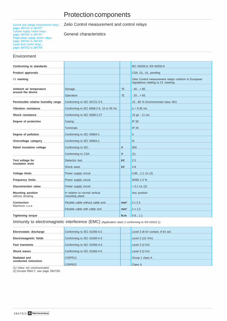
Te 28470/2 Protection components Zelio Control measurement and control relays General characteristics Environment Conforming to standards IEC 60255-6, EN 60255-6 Product approvals CSA, GL, UL, pending è marking Zelio Control measurement relays conform to European regulations relating to è marking Ambient air temperature Storage °C - 40…+ 85 around the device Operation °C - 20…+ 65 Permissible relative humidity range Conforming to IEC 60721-3-3 15…85 % Environmental class 3K3 Vibration resistance Conforming to IEC 6068-2-6, 10 to 55 Hz a = 0.35 ms Shock resistance Conforming to IEC 6068-2-27 15 gn - 11 ms Degree of protection Casing IP 50 Terminals IP 20 Degree of pollution Conforming to IEC 60664-1 3 Overvoltage category Conforming to IEC 60664-1 III Rated insulation voltage Conforming to IEC V 500 Conforming to CSA V (1) Test voltage for Dielectric test kV 2.5 insulation tests Shock wave kV 4.8 Voltage limits Power supply circuit 0.85…1.1 Uc (2) Frequency limits Power supply circuit 50/60 ± 5 % Disconnection value Power supply circuit > 0.1 Uc (2) Mounting position In relation to normal vertical Any position without derating mounting plane Connection Flexible cable without cable end mm 2 2 x 2.5 Maximum c.s.a. Flexible cable with cable end mm 2 2 x 1.5 Tightening torque N.m 0.6…1.1 Immunity to electromagnetic interference (EMC) (Application class 2 conforming to EN 61812-1) Electrostatic discharge Conforming to IEC 61000-4-2 Level 3 (6 kV contact, 8 kV air) Electromagnetic fields Conforming to IEC 61000-4-3 Level 3 (10 V/m) Fast transients Conforming to IEC 61000-4-4 Level 3 (2 kV) Shock waves Conforming to IEC 61000-4-5 Level 3 (2 kV) Radiated and CISPR11 Group 1 class A conducted emissions CISPR22 Class A (1) Value not communicated. (2) Except RM4-T, see page 28473/5. Current and voltage measurement relays : pages 28471/2 to 28472/7 3-phase supply control relays : pages 28473/2 to 28473/7 Single-phase supply control relays : pages 28474/2 to 28474/5 Liquid level control relays : pages 28475/2 to 28475/5
Transcript of ZELIO CONTROL - MEASUREMENT AND CONTROL RELAYS … Automatyka przemyslowa/Przekazniki... · 28471/2...
Te2 8 4 7 0 / 2
Protection componentsZelio Control measurement and control relays
General characteristics
Environment
Conforming to standards IEC 60255-6, EN 60255-6
Product approvals CSA, GL, UL, pending
è marking Zelio Control measurement relays conform to Europeanregulations relating to è marking
Ambient air temperature Storage °C - 40…+ 85around the device
Operation °C - 20…+ 65
Permissible relative humidity range Conforming to IEC 60721-3-3 15…85 % Environmental class 3K3
Vibration resistance Conforming to IEC 6068-2-6, 10 to 55 Hz a = 0.35 ms
Shock resistance Conforming to IEC 6068-2-27 15 gn - 11 ms
Degree of protection Casing IP 50
Terminals IP 20
Degree of pollution Conforming to IEC 60664-1 3
Overvoltage category Conforming to IEC 60664-1 III
Rated insulation voltage Conforming to IEC V 500
Conforming to CSA V (1)
Test voltage for Dielectric test kV 2.5insulation tests
Shock wave kV 4.8
Voltage limits Power supply circuit 0.85…1.1 Uc (2)
Frequency limits Power supply circuit 50/60 ± 5 %
Disconnection value Power supply circuit > 0.1 Uc (2)
Mounting position In relation to normal vertical Any positionwithout derating mounting plane
Connection Flexible cable without cable end mm 2 2 x 2.5Maximum c.s.a.
Flexible cable with cable end mm 2 2 x 1.5
Tightening torque N.m 0.6…1.1
Immunity to electromagnetic interference (EMC) (Application class 2 conforming to EN 61812-1)
Electrostatic discharge Conforming to IEC 61000-4-2 Level 3 (6 kV contact, 8 kV air)
Electromagnetic fields Conforming to IEC 61000-4-3 Level 3 (10 V/m)
Fast transients Conforming to IEC 61000-4-4 Level 3 (2 kV)
Shock waves Conforming to IEC 61000-4-5 Level 3 (2 kV)
Radiated and CISPR11 Group 1 class Aconducted emissions
CISPR22 Class A(1) Value not communicated.(2) Except RM4-T, see page 28473/5.
Current and voltage measurement relays :pages 28471/2 to 28472/73-phase supply control relays :pages 28473/2 to 28473/7Single-phase supply control relays :pages 28474/2 to 28474/5Liquid level control relays :pages 28475/2 to 28475/5
2 8 4 7 0 / 3Te
Protection componentsZelio Control measurement and control relays
General characteristics (continued)
Output circuit characteristics
Mechanical durability In millions of operating cycles 30
Current limit Ith A 8
Rated operational limits at 70 °C 24 V 115 V 250 VConforming to IEC 60947-5-1/1991and VDE 0660 AC-15 A 3 3 3
DC-13 A 2 0.3 0.1
Minimum switching capacity 12 V/10 mA
Switching voltage Rated V c 250
Max V c 440
Contact material Nickel Silver 90/10
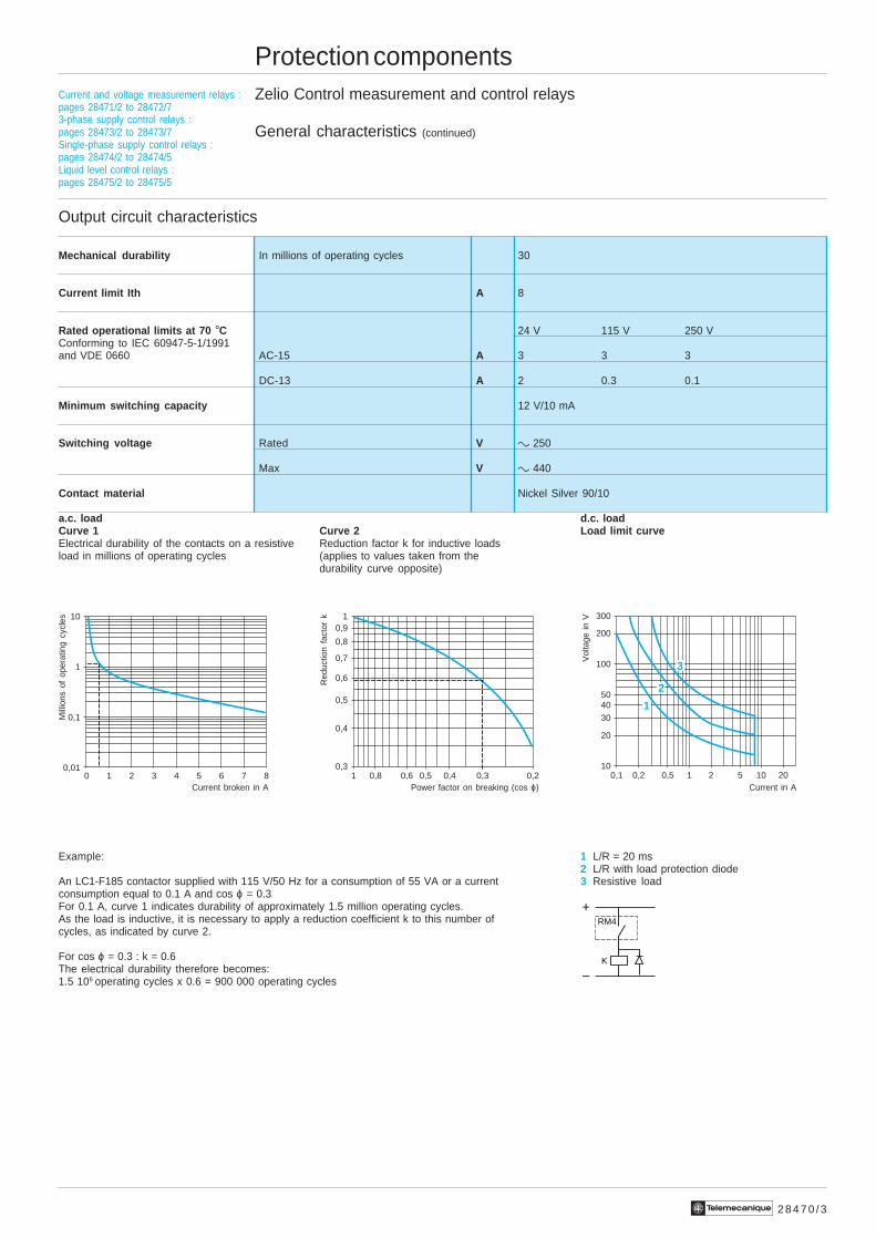
a.c. load d.c. loadCurve 1 Curve 2 Load limit curveElectrical durability of the contacts on a resistive Reduction factor k for inductive loadsload in millions of operating cycles (applies to values taken from the
durability curve opposite)
Example: 1 L/R = 20 ms2 L/R with load protection diode
An LC1-F185 contactor supplied with 115 V/50 Hz for a consumption of 55 VA or a current 3 Resistive loadconsumption equal to 0.1 A and cos ϕ = 0.3For 0.1 A, curve 1 indicates durability of approximately 1.5 million operating cycles.As the load is inductive, it is necessary to apply a reduction coefficient k to this number ofcycles, as indicated by curve 2.
For cos ϕ = 0.3 : k = 0.6The electrical durability therefore becomes:1.5 106 operating cycles x 0.6 = 900 000 operating cycles
10
1
0,1
0,010 1 2 3 4 5 6 7 8
1
0,6
0,5
0,9
0,8
0,7
0,4
0,31 0,8 0,6 0,5 0,4 0,3 0,2
300
40
30
200
100
50
20
100,1 0,2 0,5 1 2 5 2010
1
2
3
Current broken in A Power factor on breaking (cos ϕ) Current in A
Mill
ions
of
oper
atin
g cy
cles
Red
uctio
n fa
ctor
k
Vol
tage
in V
Current and voltage measurement relays :pages 28471/2 to 28472/73-phase supply control relays :pages 28473/2 to 28473/7Single-phase supply control relays :pages 28474/2 to 28474/5Liquid level control relays :pages 28475/2 to 28475/5
RM4
K
+
–
2 8 4 7 1 / 2 Te
Protection componentsZelio Control measurement and control relaysCurrent measurement relays RM4-JA
Presentation
Functions
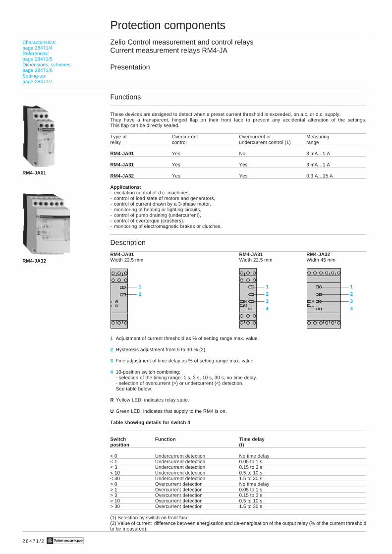
These devices are designed to detect when a preset current threshold is exceeded, on a.c. or d.c. supply.They have a transparent, hinged flap on their front face to prevent any accidental alteration of the settings.This flap can be directly sealed.
Type of Overcurrent Overcurrent or Measuringrelay control undercurrent control (1) range
RM4-JA01 Yes No 3 mA…1 A
RM4-JA31 Yes Yes 3 mA…1 A
RM4-JA32 Yes Yes 0.3 A…15 A
Applications :- excitation control of d.c. machines,- control of load state of motors and generators,- control of current drawn by a 3-phase motor,- monitoring of heating or lighting circuits,- control of pump draining (undercurrent),- control of overtorque (crushers).- monitoring of electromagnetic brakes or clutches.
Description
RM4-JA01 RM4-JA31 RM4-JA32Width 22.5 mm Width 22.5 mm Width 45 mm
1 Adjustment of current threshold as % of setting range max. value.
2 Hysteresis adjustment from 5 to 30 % (2).
3 Fine adjustment of time delay as % of setting range max. value.
4 10-position switch combining:- selection of the timing range: 1 s, 3 s, 10 s, 30 s, no time delay.- selection of overcurrent (>) or undercurrent (<) detection.See table below.
R Yellow LED: indicates relay state.
U Green LED: indicates that supply to the RM4 is on.
Table showing details for switch 4
Switch Function Time delayposition (t)
< 0 Undercurrent detection No time delay< 1 Undercurrent detection 0.05 to 1 s< 3 Undercurrent detection 0.15 to 3 s< 10 Undercurrent detection 0.5 to 10 s< 30 Undercurrent detection 1.5 to 30 s> 0 Overcurrent detection No time delay> 1 Overcurrent detection 0.05 to 1 s> 3 Overcurrent detection 0.15 to 3 s> 10 Overcurrent detection 0.5 to 10 s> 30 Overcurrent detection 1.5 to 30 s
(1) Selection by switch on front face.(2) Value of current difference between energisation and de-energisation of the output relay (% of the current thresholdto be measured).
RM4-JA01
Characteristics:page 28471/4References:page 28471/5Dimensions, schemes:page 28471/6Setting-up:page 28471/7
RM4-JA32
12
RU
1234
RU
1234
RU
2 8 4 7 1 / 3Te
t: time delay
B1, B2, B3RM4-JA
C
Protection componentsZelio Control measurement and control relaysCurrent measurement relays RM4-JA
Presentation (continued)
Operating principle
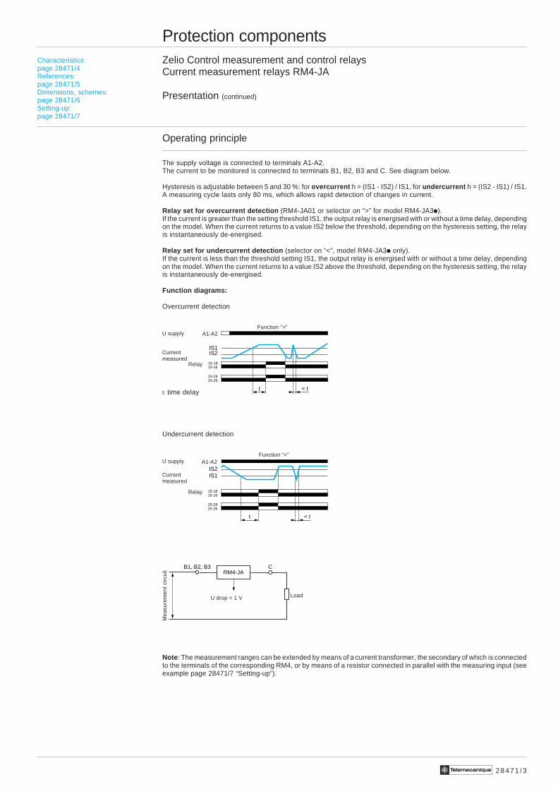
The supply voltage is connected to terminals A1-A2.The current to be monitored is connected to terminals B1, B2, B3 and C. See diagram below.
Hysteresis is adjustable between 5 and 30 %: for overcurrent h = (IS1 - IS2) / IS1, for undercurrent h = (IS2 - IS1) / IS1.A measuring cycle lasts only 80 ms, which allows rapid detection of changes in current.
Relay set for overcurrent detection (RM4-JA01 or selector on “>” for model RM4-JA3i).If the current is greater than the setting threshold IS1, the output relay is energised with or without a time delay, dependingon the model. When the current returns to a value IS2 below the threshold, depending on the hysteresis setting, the relayis instantaneously de-energised.
Relay set for undercurrent detection (selector on “<”, model RM4-JA3i only).If the current is less than the threshold setting IS1, the output relay is energised with or without a time delay, dependingon the model. When the current returns to a value IS2 above the threshold, depending on the hysteresis setting, the relayis instantaneously de-energised.
Function diagrams:
Overcurrent detection
Undercurrent detection
Note : The measurement ranges can be extended by means of a current transformer, the secondary of which is connectedto the terminals of the corresponding RM4, or by means of a resistor connected in parallel with the measuring input (seeexample page 28471/7 “Setting-up”).
Currentmeasured
Relay
t < t
IS1IS2
15-1815-16
25-2825-26
A1-A2U supply
t < t
IS1IS2
15-1815-16
25-2825-26
A1-A2
Currentmeasured
Relay
U supply
Characteristics:page 28471/4References:page 28471/5Dimensions, schemes:page 28471/6Setting-up:page 28471/7
Function “>”
Function “<”
Mea
sure
men
t ci
rcui
t
U drop < 1 V Load
2 8 4 7 1 / 4 Te
Protection componentsZelio Control measurement and control relaysCurrent measurement relays RM4-JA
Characteristics
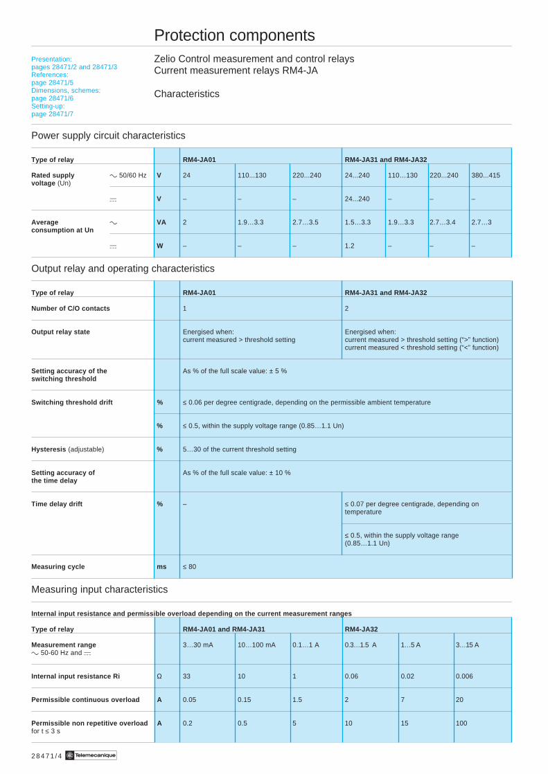
Power supply circuit characteristics
Type of relay RM4-JA01 RM4-JA31 and RM4-JA32
Rated supply c 50/60 Hz V 24 110...130 220...240 24...240 110…130 220...240 380...415voltage (Un)
a V – – – 24...240 – – –
Average c VA 2 1.9…3.3 2.7…3.5 1.5…3.3 1.9…3.3 2.7…3.4 2.7…3consumption at Un
a W – – – 1.2 – – –
Output relay and operating characteristics
Type of relay RM4-JA01 RM4-JA31 and RM4-JA32
Number of C/O contacts 1 2
Output relay state Energised when: Energised when:current measured > threshold setting current measured > threshold setting (“>” function)
current measured < threshold setting (“<” function)
Setting accuracy of the As % of the full scale value: ± 5 %switching threshold
Switching threshold drift % ≤ 0.06 per degree centigrade, depending on the permissible ambient temperature
% ≤ 0.5, within the supply voltage range (0.85…1.1 Un)
Hysteresis (adjustable) % 5…30 of the current threshold setting
Setting accuracy of As % of the full scale value: ± 10 %the time delay
Time delay drift % – ≤ 0.07 per degree centigrade, depending ontemperature
≤ 0.5, within the supply voltage range(0.85…1.1 Un)
Measuring cycle ms ≤ 80
Measuring input characteristics
Internal input resistance and permissible overload depending on the current measurement ranges
Type of relay RM4-JA01 and RM4-JA31 RM4-JA32
Measurement range 3…30 mA 10…100 mA 0.1…1 A 0.3…1.5 A 1…5 A 3…15 Ac 50-60 Hz and a
Internal input resistance Ri Ω 33 10 1 0.06 0.02 0.006
Permissible continuous overload A 0.05 0.15 1.5 2 7 20
Permissible non repetitive overload A 0.2 0.5 5 10 15 100for t ≤ 3 s
Presentation:pages 28471/2 and 28471/3References:page 28471/5Dimensions, schemes:page 28471/6Setting-up:page 28471/7
2 8 4 7 1 / 5Te
Protection componentsZelio Control measurement and control relaysCurrent measurement relays RM4-JA
References
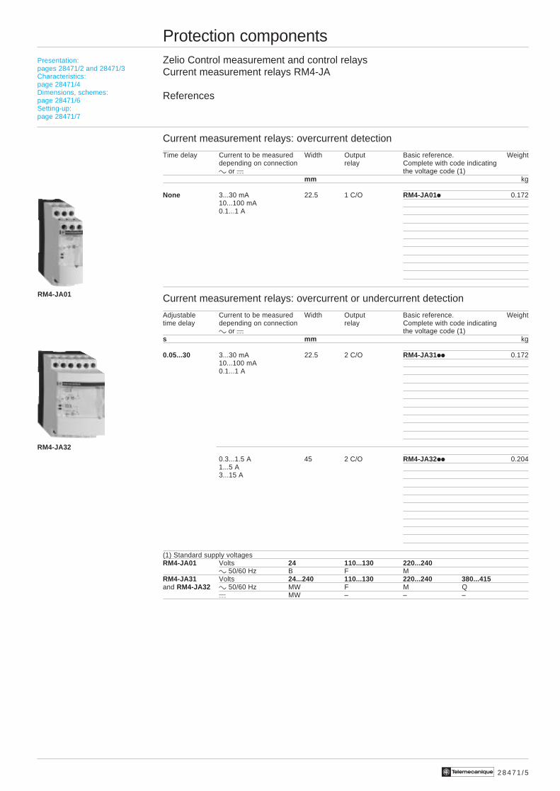
Current measurement relays: overcurrent detection
Time delay Current to be measured Width Output Basic reference. Weightdepending on connection relay Complete with code indicatingc or a the voltage code (1)
mm kg
None 3...30 mA 22.5 1 C/O RM4-JA01i 0.17210...100 mA0.1...1 A
Current measurement relays: overcurrent or undercurrent detection
Adjustable Current to be measured Width Output Basic reference. Weighttime delay depending on connection relay Complete with code indicating
c or a the voltage code (1)s mm kg
0.05...30 3...30 mA 22.5 2 C/O RM4-JA31ii 0.17210...100 mA0.1...1 A
0.3...1.5 A 45 2 C/O RM4-JA32ii 0.2041...5 A3...15 A
(1) Standard supply voltagesRM4-JA01 Volts 24 110...130 220...240
c 50/60 Hz B F MRM4-JA31 Volts 24...240 110...130 220...240 380...415and RM4-JA32 c 50/60 Hz MW F M Q
a MW – – –
Presentation:pages 28471/2 and 28471/3Characteristics:page 28471/4Dimensions, schemes:page 28471/6Setting-up:page 28471/7
RM4-JA32
RM4-JA01
2 8 4 7 1 / 6 Te
Protection componentsZelio Control measurement and control relaysCurrent measurement relays RM4-JA
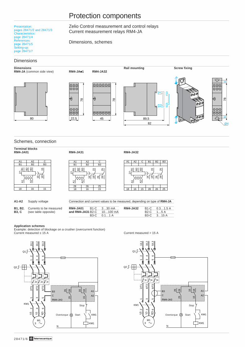
Dimensions, schemes
Dimensions
Dimensions Rail mounting Screw fixingRM4-JA (common side view) RM4-JAi1 RM4-JA32
Schemes, connection
Terminal blocksRM4-JA01 RM4-JA31 RM4-JA32
A1-A2 Supply voltage Connection and current values to be measured, depending on type of RM4-JA
B1, B2. Currents to be measured RM4-JA01 B1-C 3…30 mA RM4-JA32 B1-C 0.3…1.5 AB3, C (see table opposite) and RM4-JA31 B2-C 10…100 mA B2-C 1…5 A
B3-C 0.1…1 A B3-C 3…15 A
Application schemesExample: detection of blockage on a crusher (overcurrent function)Current measured ≤ 15 A Current measured > 15 A
Presentation:pages 28471/2 and 28471/3Characteristics:page 28471/4References:page 28471/5Setting-up:page 28471/7
80 22,5 89,5
82 Ø4
66
7878
45
78
A1 A2 CB1 B3B2
2628 2518 16 15
1815
16
B3
2825
26
B2
B1
A2
A1
C
A1 A2 C B1 B2 B3
18 16 15 28 26 25
1815
16
B3
2825
26
B2
B1
A2
A1
C
A1 A2 CB1 B3B2
18 16 15
1815
16
B3
B2
B1
A2
A1
C
151816
252826
RM4-JA3
KM1
KM1
1/L1
2
3/L2
4
5/L3
6
Q1
2/T
1
4/T
2
6/T
3
1
Q2
3 5
KM1
12
34
56
U1
W1
V1
M1 3
B3
C
A1
A2
N
Overtorque Start
Stop
151816
252826
RM4-JA3
KM1
KM1
1/L1
2
3/L2
4
5/L3
6
Q1
2/T
1
4/T
2
6/T
3
1
Q2
3 5
KM1
12
34
56
U1
W1
V1
M1 3
B3
C
A1
A2
N
Overtorque Start
Stop
2 8 4 7 1 / 7Te
10(2 x 1/0.1) - 1
Protection componentsZelio Control measurement and control relaysCurrent measurement relays RM4-JA
Setting-up
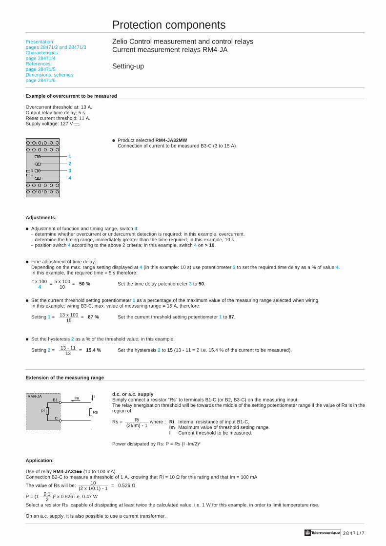
Example of overcurrent to be measured
Overcurrent threshold at: 13 A.Output relay time delay: 5 s.Reset current threshold: 11 A.Supply voltage: 127 V a.
i Product selected RM4-JA32MWConnection of current to be measured B3-C (3 to 15 A)
Adjustments:
i Adjustment of function and timing range, switch 4:- determine whether overcurrent or undercurrent detection is required; in this example, overcurrent.- determine the timing range, immediately greater than the time required; in this example, 10 s.- position switch 4 according to the above 2 criteria; in this example, switch 4 on > 10.
i Fine adjustment of time delay:Depending on the max. range setting displayed at 4 (in this example: 10 s) use potentiometer 3 to set the required time delay as a % of value 4.In this example, the required time = 5 s therefore:
= = 50 % Set the time delay potentiometer 3 to 50.
i Set the current threshold setting potentiometer 1 as a percentage of the maximum value of the measuring range selected when wiring.In this example: wiring B3-C, max. value of measuring range = 15 A, therefore:
Setting 1 = = 87 % Set the current threshold setting potentiometer 1 to 87.
i Set the hysteresis 2 as a % of the threshold value; in this example:
Setting 2 = = 15.4 % Set the hysteresis 2 to 15 (13 - 11 = 2 i.e. 15.4 % of the current to be measured).
Extension of the measuring range
d.c. or a.c. supplySimply connect a resistor “Rs” to terminals B1-C (or B2, B3-C) on the measuring input.The relay energisation threshold will be towards the middle of the setting potentiometer range if the value of Rs is in theregion of:
Rs = where : Ri Internal resistance of input B1-C.Im Maximum value of threshold setting range.I Current threshold to be measured.
Power dissipated by Rs: P = Rs (I -Im/2)2
Application:
Use of relay RM4-JA31ii (10 to 100 mA).Connection B2-C to measure a threshold of 1 A, knowing that Ri = 10 Ω for this rating and that Im = 100 mA
The value of Rs will be: = 0.526 Ω
P = (1 - )2 x 0.526 i.e. 0.47 W
Select a resistor Rs capable of dissipating at least twice the calculated value, i.e. 1 W for this example, in order to limit temperature rise.
On an a.c. supply, it is also possible to use a current transformer.
1234
RU
t x 1004
5 x 10010
13 x 10015
13 - 1113
Presentation:pages 28471/2 and 28471/3Characteristics:page 28471/4References:page 28471/5Dimensions, schemes:page 28471/6
Ri(2I/Im) - 1
0.12
Rs
B1
C
RM4-JA
Ri
Im I
2 8 4 7 2 / 2 Te
Protection componentsZelio Control measurement and control relaysVoltage measurement relays RM4-UA
Presentation
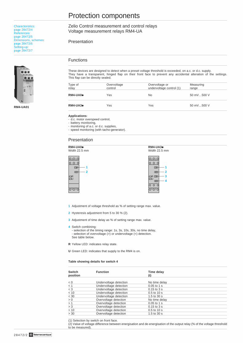
Functions
These devices are designed to detect when a preset voltage threshold is exceeded, on a.c. or d.c. supply.They have a transparent, hinged flap on their front face to prevent any accidental alteration of the settings.This flap can be directly sealed.
Type of Overvoltage Overvoltage or Measuringrelay control undervoltage control (1) range
RM4-UA0i Yes No 50 mV…500 V
RM4-UA3i Yes Yes 50 mV…500 V
Applications :- d.c. motor overspeed control,- battery monitoring,- monitoring of a.c. or d.c. supplies,- speed monitoring (with tacho-generator).
Presentation
RM4-UA0i RM4-UA3iWidth 22.5 mm Width 22.5 mm
1 Adjustment of voltage threshold as % of setting range max. value.
2 Hysteresis adjustment from 5 to 30 % (2).
3 Adjustment of time delay as % of setting range max. value.
4 Switch combining:- selection of the timing range: 1s, 3s, 10s, 30s, no time delay,- selection of overvoltage (>) or undervoltage (<) detection.See table below.
R Yellow LED: indicates relay state.
U Green LED: indicates that supply to the RM4 is on.
Table showing details for switch 4
Switch Function Time delayposition (t)
< 0 Undervoltage detection No time delay< 1 Undervoltage detection 0.05 to 1 s< 3 Undervoltage detection 0.15 to 3 s< 10 Undervoltage detection 0.5 to 10 s< 30 Undervoltage detection 1.5 to 30 s> 0 Overvoltage detection No time delay> 1 Overvoltage detection 0.05 to 1 s> 3 Overvoltage detection 0.15 to 3 s> 10 Overvoltage detection 0.5 to 10 s> 30 Overvoltage detection 1.5 to 30 s
(1) Selection by switch on front face.(2) Value of voltage difference between energisation and de-energisation of the output relay (% of the voltage thresholdto be measured).
RM4-UA01
Characteristics:page 28472/4References:page 28472/5Dimensions, schemes:page 28472/6Setting-up:page 28472/7
12
RU
1234
RU
2 8 4 7 2 / 3Te
Voltagemeasured
Voltagemeasured
t: time delay
Protection componentsZelio Control measurement and control relaysVoltage measurement relays RM4-UA
Presentation (continued)
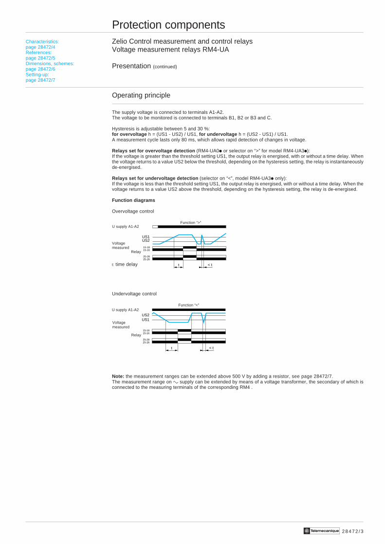
Operating principle
The supply voltage is connected to terminals A1-A2.The voltage to be monitored is connected to terminals B1, B2 or B3 and C.
Hysteresis is adjustable between 5 and 30 %:for overvoltage h = (US1 - US2) / US1, for undervoltage h = (US2 - US1) / US1.A measurement cycle lasts only 80 ms, which allows rapid detection of changes in voltage.
Relays set for overvoltage detection (RM4-UA0i or selector on “>” for model RM4-UA3i):If the voltage is greater than the threshold setting US1, the output relay is energised, with or without a time delay. Whenthe voltage returns to a value US2 below the threshold, depending on the hysteresis setting, the relay is instantaneouslyde-energised.
Relays set for undervoltage detection (selector on “<”, model RM4-UA3i only):If the voltage is less than the threshold setting US1, the output relay is energised, with or without a time delay. When thevoltage returns to a value US2 above the threshold, depending on the hysteresis setting, the relay is de-energised.
Function diagrams
Overvoltage control
Undervoltage control
Note: the measurement ranges can be extended above 500 V by adding a resistor, see page 28472/7.The measurement range on c supply can be extended by means of a voltage transformer, the secondary of which isconnected to the measuring terminals of the corresponding RM4 .
Characteristics:page 28472/4References:page 28472/5Dimensions, schemes:page 28472/6Setting-up:page 28472/7
Function “>”
Function “<”
U supply A1-A2
U supply A1-A2
Relay
Relay
t < t
US1US2
15-1815-16
25-2825-26
t < t
US1US2
15-1815-16
25-2825-26
2 8 4 7 2 / 4 Te
Protection componentsZelio Control measurement and control relaysVoltage measurement relays RM4-UA
Characteristics
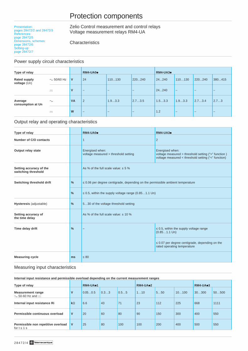
Power supply circuit characteristics
Type of relay RM4-UA0 i RM4-UA3i
Rated supply c 50/60 Hz V 24 110...130 220...240 24...240 110…130 220...240 380...415voltage (Un)
a V – – – 24...240 – – –
Average c VA 2 1.9…3.3 2.7…3.5 1.5…3.3 1.9…3.3 2.7…3.4 2.7…3consumption at Un
a W – – – 1.2 – – –
Output relay and operating characteristics
Type of relay RM4-UA0 i RM4-UA3i
Number of C/O contacts 1 2
Output relay state Energised when: Energised when:voltage measured > threshold setting voltage measured > threshold setting (“>” function )
voltage measured < threshold setting (“<” function)
Setting accuracy of the As % of the full scale value: ± 5 %switching threshold
Switching threshold drift % ≤ 0.06 per degree centigrade, depending on the permissible ambient temperature
% ≤ 0.5, within the supply voltage range (0.85…1.1 Un)
Hysteresis (adjustable) % 5…30 of the voltage threshold setting
Setting accuracy of As % of the full scale value: ± 10 %the time delay
Time delay drift % – ≤ 0.5, within the supply voltage range(0.85…1.1 Un)
≤ 0.07 per degree centigrade, depending on therated operating temperature
Measuring cycle ms ≤ 80
Measuring input characteristics
Internal input resistance and permissible overload depending on the current measurement ranges
Type of relay RM4-UA i1 RM4-UAi2 RM4-UAi3
Measurement range V 0.05…0.5 0.3…3 0.5…5 1…10 5…50 10…100 30…300 50…500c 50-60 Hz and a
Internal input resistance Ri k Ω 6.6 43 71 23 112 225 668 1111
Permissible continuous overload V 20 60 80 90 150 300 400 550
Permissible non repetitive overload V 25 80 100 100 200 400 500 550for t ≤ 1 s
Presentation:pages 28472/2 and 28472/3References:page 28472/5Dimensions, schemes:page 28472/6Setting-up:page 28472/7
2 8 4 7 2 / 5Te
Protection componentsZelio Control measurement and control relaysVoltage measurement relays RM4-UA
References
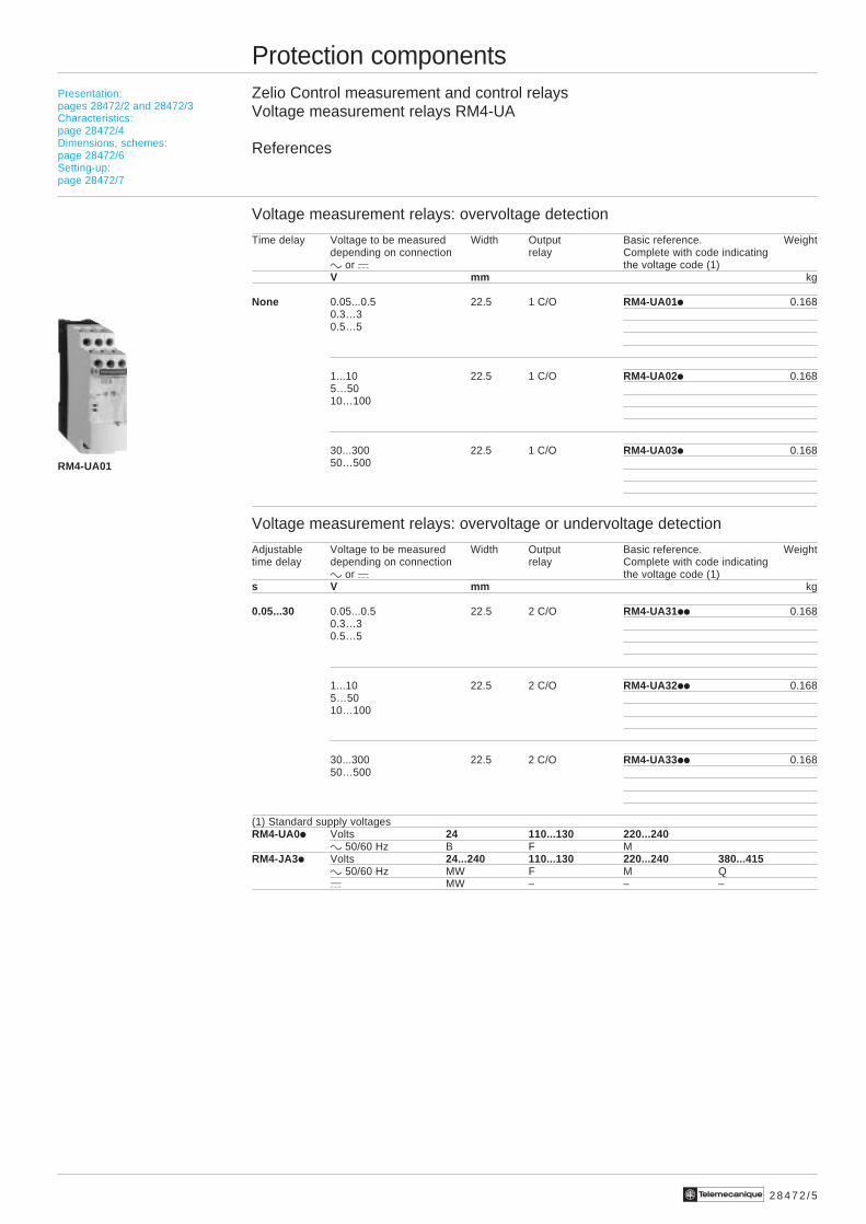
Voltage measurement relays: overvoltage detection
Time delay Voltage to be measured Width Output Basic reference. Weightdepending on connection relay Complete with code indicatingc or a the voltage code (1)V mm kg
None 0.05...0.5 22.5 1 C/O RM4-UA01i 0.1680.3…30.5…5
1...10 22.5 1 C/O RM4-UA02i 0.1685…5010…100
30...300 22.5 1 C/O RM4-UA03i 0.16850…500
Voltage measurement relays: overvoltage or undervoltage detection
Adjustable Voltage to be measured Width Output Basic reference. Weighttime delay depending on connection relay Complete with code indicating
c or a the voltage code (1)s V mm kg
0.05...30 0.05...0.5 22.5 2 C/O RM4-UA31ii 0.1680.3…30.5…5
1...10 22.5 2 C/O RM4-UA32ii 0.1685…5010…100
30...300 22.5 2 C/O RM4-UA33ii 0.16850…500
(1) Standard supply voltagesRM4-UA0i Volts 24 110...130 220...240
c 50/60 Hz B F MRM4-JA3i Volts 24...240 110...130 220...240 380...415
c 50/60 Hz MW F M Qa MW – – –
Presentation:pages 28472/2 and 28472/3Characteristics:page 28472/4Dimensions, schemes:page 28472/6Setting-up:page 28472/7
RM4-UA01
2 8 4 7 2 / 6 Te
Protection componentsZelio Control measurement and control relaysVoltage measurement relays RM4-UA
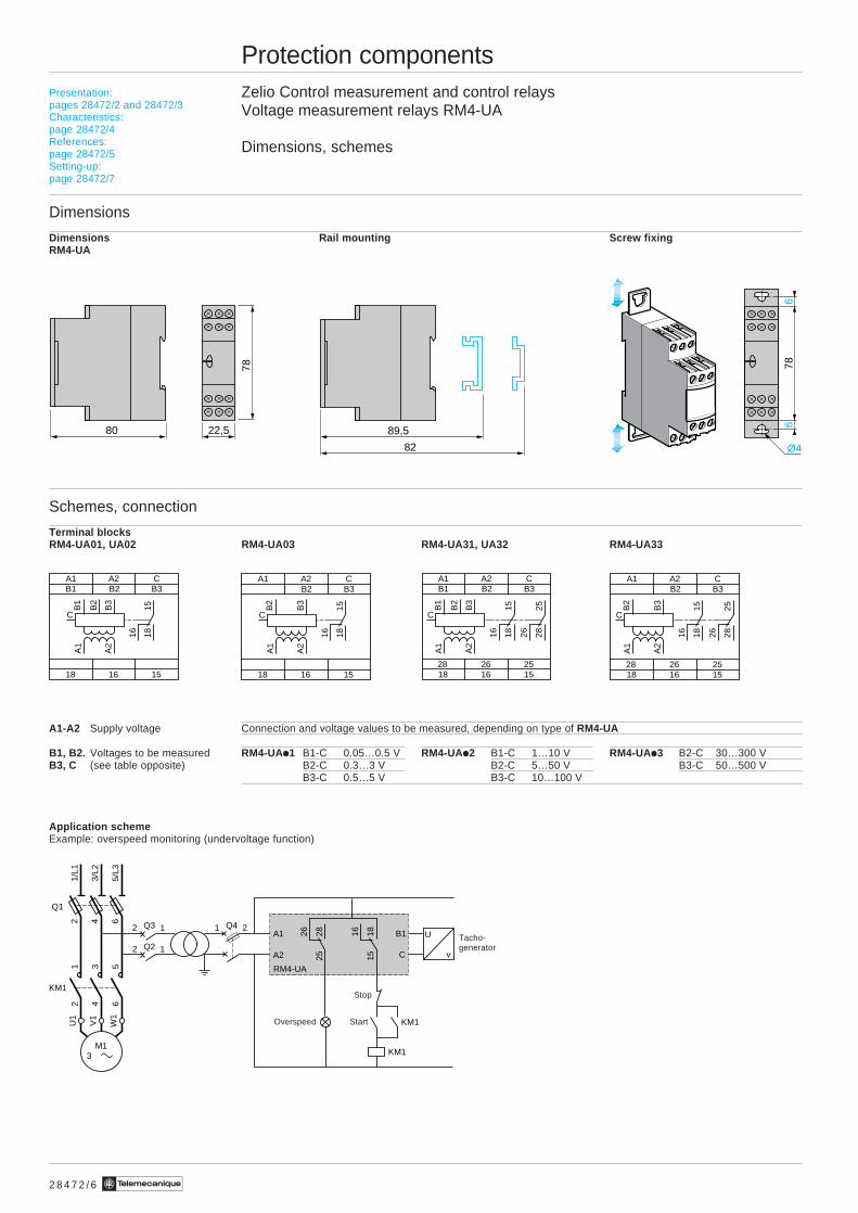
Dimensions, schemes
Dimensions
Dimensions Rail mounting Screw fixingRM4-UA
Schemes, connection
Terminal blocksRM4-UA01, UA02 RM4-UA03 RM4-UA31, UA32 RM4-UA33
A1-A2 Supply voltage Connection and voltage values to be measured, depending on type of RM4-UA
B1, B2. Voltages to be measured RM4-UAi1 B1-C 0.05…0.5 V RM4-UAi2 B1-C 1…10 V RM4-UAi3 B2-C 30…300 VB3, C (see table opposite) B2-C 0.3…3 V B2-C 5…50 V B3-C 50…500 V
B3-C 0.5…5 V B3-C 10…100 V
Application schemeExample: overspeed monitoring (undervoltage function)
Presentation:pages 28472/2 and 28472/3Characteristics:page 28472/4References:page 28472/5Setting-up:page 28472/7
A1 A2 CB1 B3B2
18 16 15
1815
16
B3
B2
B1
A2
A1
C
A1 A2 CB1 B3B2
2628 2518 16 15
1815
16
B3
2825
26
B2
B1
A2
A1
C
80 22,5 89,5
82 Ø4
66
7878
Q1
1/L1
2
3/L2
4
5/L3
6 Q41 2Q32 1
Q22 1
151816
252826
RM4-UA
KM1
KM1
A1
A2
B1
C
U
v
KM1
12
34
56
U1
W1
V1
M1 3
Tacho-generator
Overspeed
Stop
Start
A1 A2 CB3B2
18 16 15
1815
16
B3
B2
A2
A1
C
A1 A2 CB3B2
2628 2518 16 15
1815
16
B3
2825
26
B2
A2
A1
C
2 8 4 7 2 / 7Te
Protection componentsZelio Control measurement and control relaysVoltage measurement relays RM4-UA
Setting-up
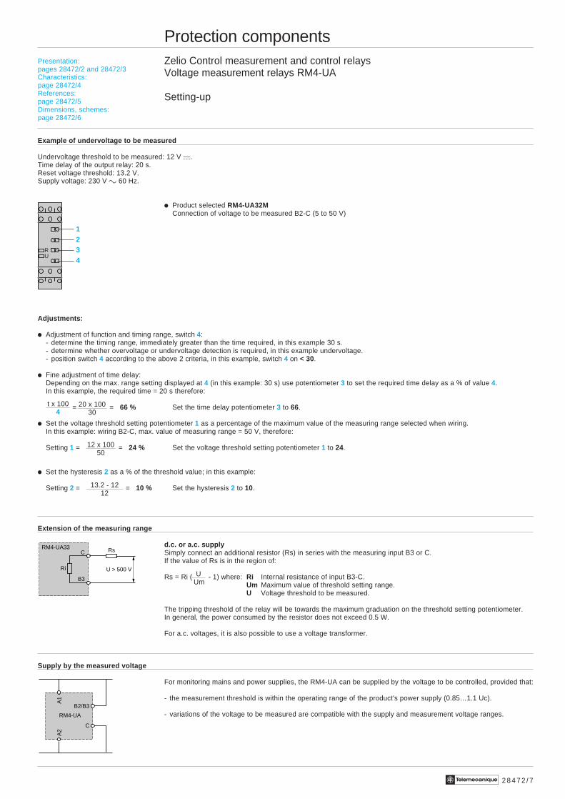
Example of undervoltage to be measured
Undervoltage threshold to be measured: 12 V a.Time delay of the output relay: 20 s.Reset voltage threshold: 13.2 V.Supply voltage: 230 V c 60 Hz.
i Product selected RM4-UA32MConnection of voltage to be measured B2-C (5 to 50 V)
Adjustments:
i Adjustment of function and timing range, switch 4:- determine the timing range, immediately greater than the time required, in this example 30 s.- determine whether overvoltage or undervoltage detection is required, in this example undervoltage.- position switch 4 according to the above 2 criteria, in this example, switch 4 on < 30.
i Fine adjustment of time delay:Depending on the max. range setting displayed at 4 (in this example: 30 s) use potentiometer 3 to set the required time delay as a % of value 4.In this example, the required time = 20 s therefore:
= = 66 % Set the time delay potentiometer 3 to 66.
i Set the voltage threshold setting potentiometer 1 as a percentage of the maximum value of the measuring range selected when wiring.In this example: wiring B2-C, max. value of measuring range = 50 V, therefore:
Setting 1 = = 24 % Set the voltage threshold setting potentiometer 1 to 24.
i Set the hysteresis 2 as a % of the threshold value; in this example:
Setting 2 = = 10 % Set the hysteresis 2 to 10.
Extension of the measuring range
d.c. or a.c. supplySimply connect an additional resistor (Rs) in series with the measuring input B3 or C.If the value of Rs is in the region of:
Rs = Ri ( - 1) where: Ri Internal resistance of input B3-C.Um Maximum value of threshold setting range.U Voltage threshold to be measured.
The tripping threshold of the relay will be towards the maximum graduation on the threshold setting potentiometer.In general, the power consumed by the resistor does not exceed 0.5 W.
For a.c. voltages, it is also possible to use a voltage transformer.
Supply by the measured voltage
For monitoring mains and power supplies, the RM4-UA can be supplied by the voltage to be controlled, provided that:
- the measurement threshold is within the operating range of the product's power supply (0.85…1.1 Uc).
- variations of the voltage to be measured are compatible with the supply and measurement voltage ranges.
t x 1004
20 x 10030
12 x 10050
13.2 - 1212
Presentation:pages 28472/2 and 28472/3Characteristics:page 28472/4References:page 28472/5Dimensions, schemes:page 28472/6
1234
RU
U Um
RsC
B3
Ri U > 500 V
RM4-UA33
A1
A2
B2/B3
C
RM4-UA
2 8 4 7 3 / 2 Te
Protection componentsZelio Control measurement and control relays3-phase supply control relays RM4-T
Presentation
Functions
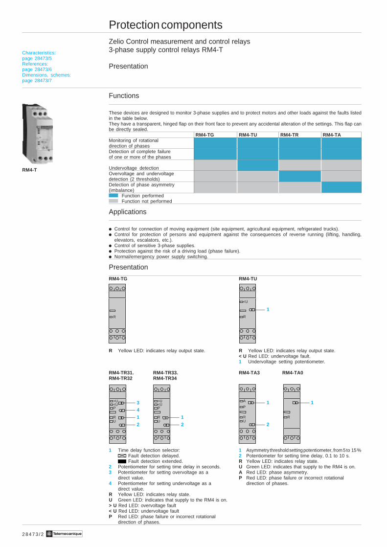
These devices are designed to monitor 3-phase supplies and to protect motors and other loads against the faults listedin the table below.They have a transparent, hinged flap on their front face to prevent any accidental alteration of the settings. This flap canbe directly sealed.
RM4-TG RM4-TU RM4-TR RM4-TAMonitoring of rotationaldirection of phasesDetection of complete failureof one or more of the phases
Undervoltage detectionOvervoltage and undervoltagedetection (2 thresholds)Detection of phase asymmetry(imbalance)
Function performedFunction not performed
Applications
i Control for connection of moving equipment (site equipment, agricultural equipment, refrigerated trucks).i Control for protection of persons and equipment against the consequences of reverse running (lifting, handling,
elevators, escalators, etc.).i Control of sensitive 3-phase supplies.i Protection against the risk of a driving load (phase failure).i Normal/emergency power supply switching.
Presentation
RM4-TG RM4-TU
R Yellow LED: indicates relay output state. R Yellow LED: indicates relay output state.< U Red LED: undervoltage fault.1 Undervoltage setting potentiometer.
RM4-TR31. RM4-TR33. RM4-TA3 RM4-TA0RM4-TR32 RM4-TR34
1 Time delay function selector: 1 Asymmetry threshold setting potentiometer, from 5 to 15 %Fault detection delayed. 2 Potentiometer for setting time delay, 0.1 to 10 s.Fault detection extended. R Yellow LED: indicates relay state.
2 Potentiometer for setting time delay in seconds. U Green LED: indicates that supply to the RM4 is on.3 Potentiometer for setting overvoltage as a A Red LED: phase asymmetry.
direct value. P Red LED: phase failure or incorrect rotational4 Potentiometer for setting undervoltage as a direction of phases.
direct value.R Yellow LED: indicates relay state.U Green LED: indicates that supply to the RM4 is on.> U Red LED: overvoltage fault< U Red LED: undervoltage faultP Red LED: phase failure or incorrect rotational
direction of phases.
RM4-T
R
1R
<U
34
1
2
RU
<UP
>U
1
2
RU
<UP
>U 1
2
RU
P
A 1
R
Characteristics:page 28473/5References:page 28473/6Dimensions, schemes:page 28473/7
2 8 4 7 3 / 3Te
Protection componentsZelio Control measurement and control relays3-phase supply control relays RM4-T
Presentation (continued)
Operating principle
The supply voltage to be monitored is connected to terminals L1, L2, L3 of the product.
There is no need to provide a separate power supply for RM4-T relays; they are self-powered by terminals L1, L2, L3.
i Monitoring rotational direction of phases and detection of complete failure of one of more of the phases(RM4-T all models)When terminals L1, L2, L3 are energised, the relay is energised and the yellow LED comes on if the rotational directionof phases is correct and if all 3 phases are present.If one or more of the phases have failed or if the rotational direction is incorrect, the relay is not energised at switch-on. In normal operation (no fault) the relay is energised; it de-energises instantaneously in the event of failure of oneor more of the phases (any time delay set is not active on these faults).In the event of failure or absence of a single phase, a voltage greater than the detection threshold (≈ 130 V on RM4-TG,undervoltage threshold setting on RM4-TU and RM4-TR) can be generated back through the control circuit, thuspreventing detection of the phase failure. In this case, we recommend the use of RM4-TA relays.The absence of a phase is signalled, on RM4-TR and RM4-TA, by illumination of led “P”.
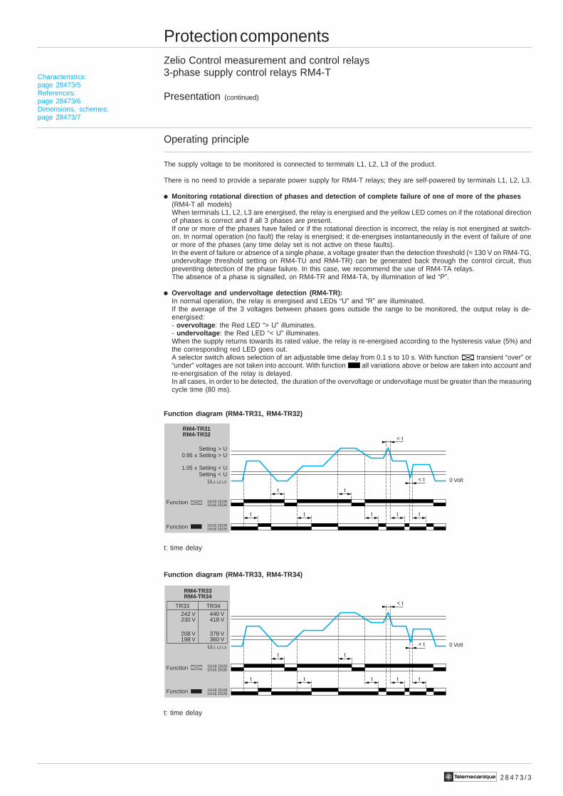
i Overvoltage and undervoltage detection (RM4-TR):In normal operation, the relay is energised and LEDs “U” and “R” are illuminated.If the average of the 3 voltages between phases goes outside the range to be monitored, the output relay is de-energised:- overvoltage : the Red LED “> U” illuminates.- undervoltage : the Red LED “< U” illuminates.When the supply returns towards its rated value, the relay is re-energised according to the hysteresis value (5%) andthe corresponding red LED goes out.A selector switch allows selection of an adjustable time delay from 0.1 s to 10 s. With function transient “over” or“under” voltages are not taken into account. With function all variations above or below are taken into account andre-energisation of the relay is delayed.In all cases, in order to be detected, the duration of the overvoltage or undervoltage must be greater than the measuringcycle time (80 ms).
Function diagram (RM4-TR31, RM4-TR32)
t: time delay
Function diagram (RM4-TR33, RM4-TR34)
t: time delay
t t
< t
t t t t t
< t
15/18 25/2815/16 25/26
15/18 25/2815/16 25/26
RM4-TR31RM4-TR32
UL1 L2 L3 0 Volt
t t
< t
t t t
< t
15/18 25/2815/16 25/26
15/18 25/2815/16 25/26
242 V 440 V230 V 418 V
208 V 378 V198 V 360 V
RM4-TR33RM4-TR34
TR33 TR34
UL1 L2 L3
t t
0 Volt
Characteristics:page 28473/5References:page 28473/6Dimensions, schemes:page 28473/7
Setting > U0.95 x Setting > U
1.05 x Setting < USetting < U
Function
Function
Function
Function
2 8 4 7 3 / 4 Te
Protection componentsZelio Control measurement and control relays3-phase supply control relays RM4-T
Presentation (continued)
Operating principle (continued)
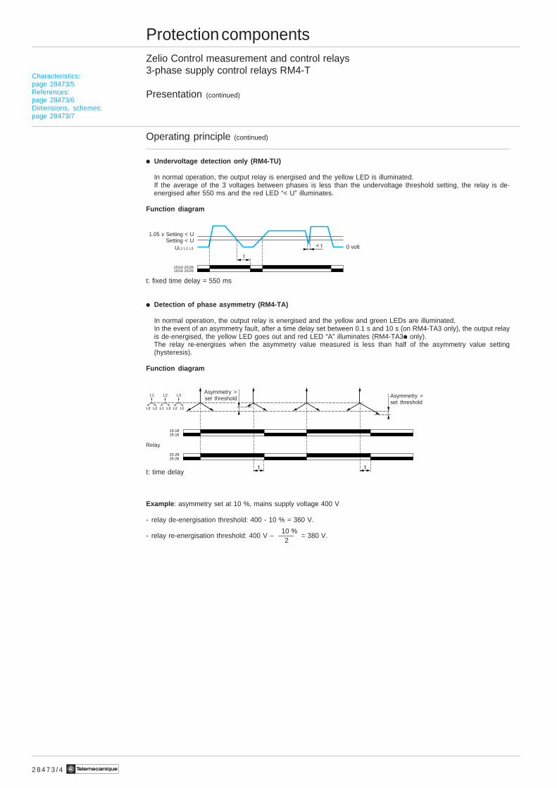
i Undervoltage detection only (RM4-TU)
In normal operation, the output relay is energised and the yellow LED is illuminated.If the average of the 3 voltages between phases is less than the undervoltage threshold setting, the relay is de-energised after 550 ms and the red LED “< U” illuminates.
Function diagram
t: fixed time delay = 550 ms
i Detection of phase asymmetry (RM4-TA)
In normal operation, the output relay is energised and the yellow and green LEDs are illuminated.In the event of an asymmetry fault, after a time delay set between 0.1 s and 10 s (on RM4-TA3 only), the output relayis de-energised, the yellow LED goes out and red LED “A” illuminates (RM4-TA3i only).The relay re-energises when the asymmetry value measured is less than half of the asymmetry value setting(hysteresis).
Function diagram
t: time delay
Example : asymmetry set at 10 %, mains supply voltage 400 V
- relay de-energisation threshold: 400 - 10 % = 360 V.
10 %- relay re-energisation threshold: 400 V – –––– = 380 V.
2
Asymmetry >set threshold
Relay
Asymmetry >set threshold
t
< t 0 volt
15/18 25/2815/16 25/26
UL1 L2 L3
Characteristics:page 28473/5References:page 28473/6Dimensions, schemes:page 28473/7
1.05 x Setting < USetting < U
15-1815-16
25-2825-26
t t
L1
L3 L2
L2
L1 L3
L3
L2 L1
2 8 4 7 3 / 5Te
Protection componentsZelio Control measurement and control relays3-phase supply control relays RM4-T
Characteristics
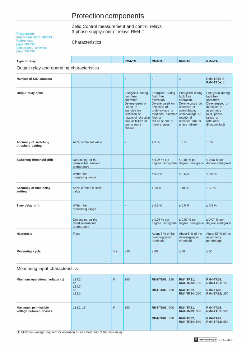
Type of relay RM4-TG RM4-TU RM4-TR RM4-TA
Output relay and operating characteristics
Number of C/O contacts 2 2 2 RM4-TA3i: 2RM4-TA0i: 1
Output relay state Energised during Energised during Energised during Energised duringfault free fault free fault free fault freeoperation. operation. operation. operation.De-energised or De-energised on De-energised on De-energised onunable to detection of detection of detection ofenergise on undervoltage or overvoltage, asymmetrydetection of rotational direction undervoltage or fault, phaserotational direction fault or rotational failure orfault or failure of failure of one or direction fault or rotationalone or more more phases phase failure direction faultphases
Accuracy of switching As % of the set value – ± 3 % ± 3 % ± 3 %threshold setting
Switching threshold drift Depending on the – ≤ 0.06 % per ≤ 0.06 % per ≤ 0.06 % perpermissible ambient degree centigrade degree centigrade degree centigradetemperature
Within the – ≤ 0.5 % ≤ 0.5 % ≤ 0.5 %measuring range
Accuracy of time delay As % of the full scale – ± 10 % ± 10 % ± 10 %setting value
Time delay drift Within the – ≤ 0.5 % ≤ 0.5 % ≤ 0.5 %measuring range
Depending on the – ≤ 0.07 % per ≤ 0.07 % per ≤ 0.07 % perrated operational degree centigrade degree centigrade degree centigradetemperature
Hysteresis Fixed – About 5 % of the About 5 % of the About 50 % of thede-energisation de-energisation asymmetrythreshold threshold percentage
Measuring cycle ms ≤ 80 ≤ 80 ≤ 80 ≤ 80
Measuring input characteristics
Minimum operational voltage (1) L1 L2 V 140 RM4-TU01: 160 RM4-TR31, RM4-TA01,or RM4-TR33: 160 RM4-TA31: 160L2 L3or RM4-TU02: 290 RM4-TR32, RM4-TA02,L1 L3 RM4-TR34: 290 RM4-TA32: 290
Maximum permissible L1 L2 L3 V 580 RM4-TU01: 300 RM4-TR31, RM4-TA01,voltage between phases RM4-TR33: 300 RM4-TA31: 300
RM4-TU02: 580 RM4-TR32, RM4-TA02,RM4-TR34: 580 RM4-TA32: 580
(1) Minimum voltage required for operation of indicators and of the time delay.
Presentation:pages 28473/2 to 28473/4References:page 28473/6Dimensions, schemes:page 28473/7
2 8 4 7 3 / 6 Te
Protection componentsZelio Control measurement and control relays3-phase supply control relays RM4-T
References
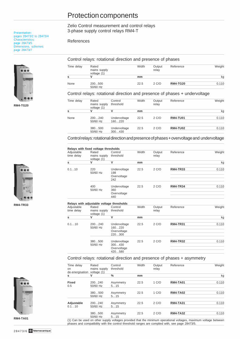
Control relays: rotational direction and presence of phases
Time delay Rated Width Output Reference Weightmains supply relayvoltage (1)
s V mm kg
None 200...500 22.5 2 C/O RM4-TG20 0.11050/60 Hz
Control relays: rotational direction and presence of phases + undervoltage
Time delay Rated Control Width Output Reference Weightmains supply threshold relayvoltage (1)
s V V mm kg
None 200…240 Undervoltage 22.5 2 C/O RM4-TU01 0.11050/60 Hz 160…220
380…500 Undervoltage 22.5 2 C/O RM4-TU02 0.11050/60 Hz 300…430
Control relays: rotational direction and presence of phases + overvoltage and undervoltage
Relays with fixed voltage thresholdsAdjustable Rated Control Width Output Reference Weighttime delay mains supply threshold relay
voltage (1)s V V mm kg
0.1...10 220 Undervoltage 22.5 2 C/O RM4-TR33 0.11050/60 Hz 198
Overvoltage242
400 Undervoltage 22.5 2 C/O RM4-TR34 0.11050/60 Hz 360
Overvoltage440
Relays with adjustable voltage thresholdsAdjustable Rated Control Width Output Reference Weighttime delay mains supply threshold relay
voltage (1)s V V mm kg
0.1…10 200…240 Undervoltage 22.5 2 C/O RM4-TR31 0.11050/60 Hz 160…220
Overvoltage220…300
380…500 Undervoltage 22.5 2 C/O RM4-TR32 0.11050/60 Hz 300…430
Overvoltage420…580
Control relays: rotational direction and presence of phases + asymmetry
Time delay Rated Control Width Output Reference Weighton mains supply threshold relayde-energisation voltage (1)s V % mm kg
Fixed 200...240 Asymmetry 22.5 1 C/O RM4-TA01 0.1100.5 50/60 Hz 5…15
380…500 Asymmetry 22.5 1 C/O RM4-TA02 0.11050/60 Hz 5…15
Adjustable 200...240 Asymmetry 22.5 2 C/O RM4-TA31 0.1100.1…10 50/60 Hz 5…15
380...500 Asymmetry 22.5 2 C/O RM4-TA32 0.11050/60 Hz 5…15
(1) Can be used on other supply voltages provided that the minimum operational voltages, maximum voltage betweenphases and compatibility with the control threshold ranges are complied with, see page 28473/5.
RM4-TG20
RM4-TR33
RM4-TA01
Presentation:pages 28473/2 to 28473/4Characteristics:page 28473/5Dimensions, schemes:page 28473/7
2 8 4 7 3 / 7Te
Protection componentsZelio Control measurement and control relays3-phase supply control relays RM4-T
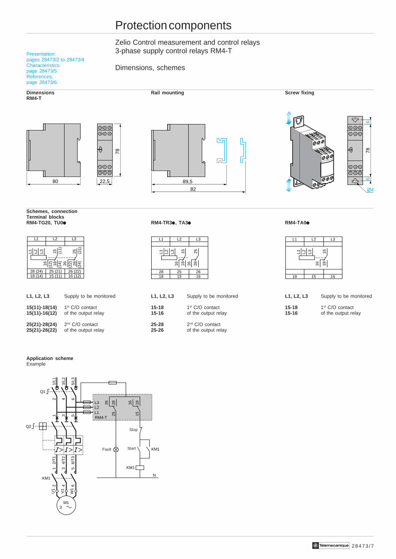
Dimensions, schemes
Dimensions Rail mounting Screw fixingRM4-T
Schemes, connectionTerminal blocksRM4-TG20, TU0iiiii RM4-TR3iiiii , TA3iiiii RM4-TA0iiiii
L1, L2, L3 Supply to be monitored L1, L2, L3 Supply to be monitored L1, L2, L3 Supply to be monitored
15(11)-18(14) 1st C/O contact 15-18 1st C/O contact 15-18 1st C/O contact15(11)-16(12) of the output relay 15-16 of the output relay 15-16 of the output relay
25(21)-28(24) 2nd C/O contact 25-28 2nd C/O contact25(21)-26(22) of the output relay 25-26 of the output relay
Application schemeExample
Presentation:pages 28473/2 to 28473/4Characteristics:page 28473/5References:page 28473/6
80 22,5 89,5
82 Ø4
66
7878
L1 L2 L3
18 15 16
1815
16
L1 L2 L3
L1 L2 L3
28 (24) 26 (22)18 (14)
25 (21)15 (11) 16 (12)
L1 L2 L3
2825 (2
1)
2616
(24)
(22)18
15 (11)
(14)
(12)
L1 L2 L3
18 15 1628 25 26
1815
16 2825
26
L1 L2 L3
151816
252826
RM4-T
KM1
KM1
1/L1
2
3/L2
4
5/L3
6
Q1
2/T
1
4/T
2
6/T
3
1
Q2
3 5
KM1
12
34
56
U1
W1
V1
M1 3
L3L2L1
N
Fault Start
Stop
2 8 4 7 4 / 2 Te
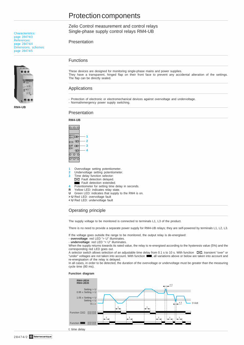
Protection componentsZelio Control measurement and control relaysSingle-phase supply control relays RM4-UB
Presentation
Functions
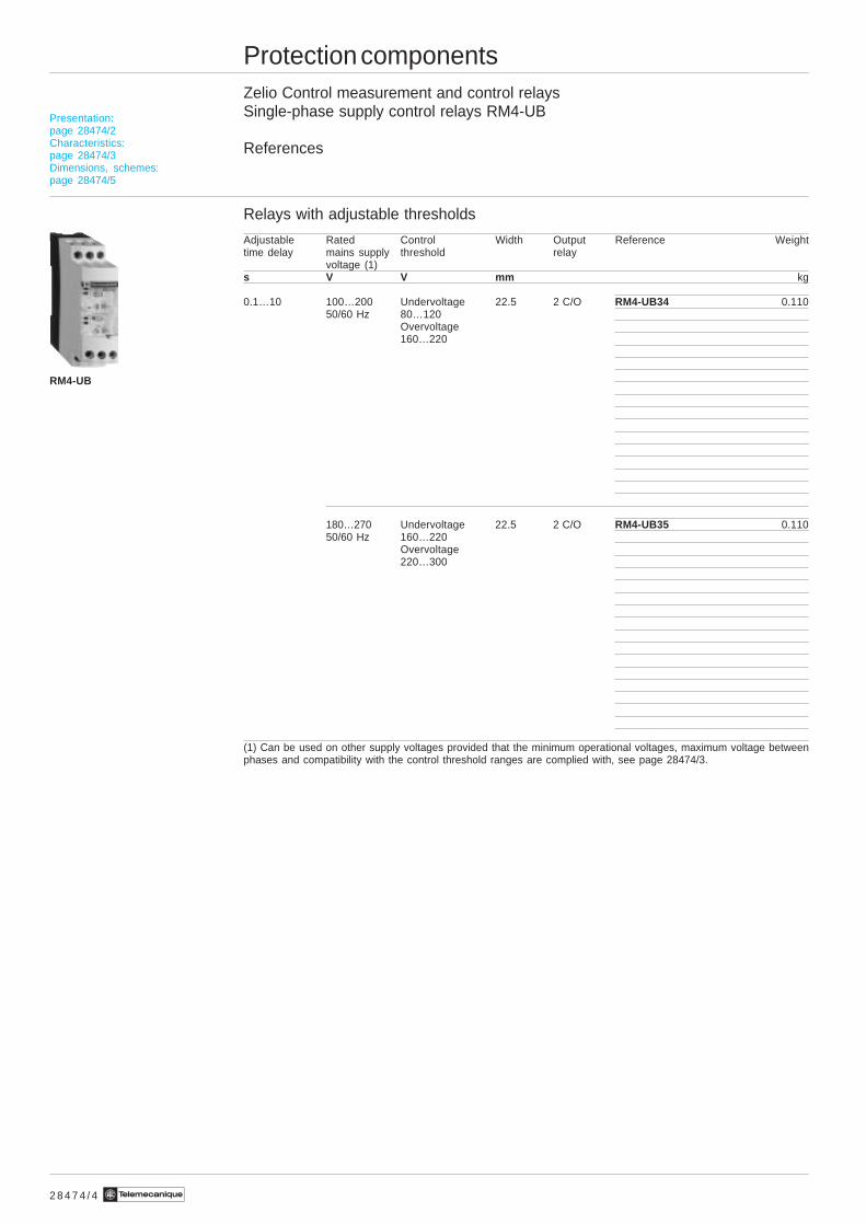
These devices are designed for monitoring single-phase mains and power supplies.They have a transparent, hinged flap on their front face to prevent any accidental alteration of the settings.The flap can be directly sealed.
Applications
- Protection of electronic or electromechanical devices against overvoltage and undervoltage.- Normal/emergency power supply switching.
Presentation
RM4-UB
1 Overvoltage setting potentiometer.2 Undervoltage setting potentiometer.3 Time delay function selector:
Fault detection delayed.Fault detection extended.
4 Potentiometer for setting time delay in seconds.R Yellow LED: indicates relay state.U Green LED: indicates that supply to the RM4 is on.> U Red LED: overvoltage fault< U Red LED: undervoltage fault
Operating principle
The supply voltage to be monitored is connected to terminals L1, L3 of the product.
There is no need to provide a separate power supply for RM4-UB relays; they are self-powered by terminals L1, L2, L3.
If the voltage goes outside the range to be monitored, the output relay is de-energised:- overvoltage : red LED “> U” illuminates.- undervoltage : red LED “< U” illuminates.When the supply returns towards its rated value, the relay is re-energised according to the hysteresis value (5%) and thecorresponding red LED goes out.A selector switch allows selection of an adjustable time delay from 0.1 s to 10 s. With function , transient “over” or“under” voltages are not taken into account. With function , all variations above or below are taken into account andre-energisation of the relay is delayed.In all cases, in order to be detected, the duration of the overvoltage or undervoltage must be greater than the measuringcycle time (80 ms).
Function diagram
t: time delay
RM4-UB
12
3
4
RU
<U>U
Characteristics:page 28474/3References:page 28474/4Dimensions, schemes:page 28474/5
t t
< t
t t t t t
< t
15/18 25/2815/16 25/26
15/18 25/2815/16 25/26
RM4-UB34RM4-UB35
UL1 L3 0 Volt
Setting > U0.95 x Setting > U
1.05 x Setting < USetting < U
Function
Function
2 8 4 7 4 / 3Te
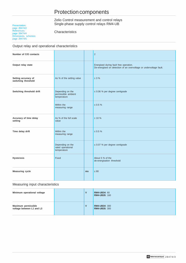
Protection componentsZelio Control measurement and control relaysSingle-phase supply control relays RM4-UB
Characteristics
Output relay and operational characteristics
Number of C/O contacts 2
Output relay state Energised during fault free operation.De-energised on detection of an overvoltage or undervoltage fault.
Setting accuracy of As % of the setting value ± 3 %switching threshold
Switching threshold drift Depending on the ≤ 0.06 % per degree centigradepermissible ambienttemperature
Within the ≤ 0.5 %measuring range
Accuracy of time delay As % of the full scale ± 10 %setting value
Time delay drift Within the ≤ 0.5 %measuring range
Depending on the ≤ 0.07 % per degree centigraderated operationaltemperature
Hysteresis Fixed About 5 % of thede-energisation threshold
Measuring cycle ms ≤ 80
Measuring input characteristics
Minimum operational voltage V RM4-UB34 : 60RM4-UB35: 160
Maximum permissible V RM4-UB34 : 300voltage between L1 and L3 RM4-UB35 : 300
Presentation:page 28474/2References:page 28474/4Dimensions, schemes:page 28474/5
2 8 4 7 4 / 4 Te
Protection componentsZelio Control measurement and control relaysSingle-phase supply control relays RM4-UB
References
Relays with adjustable thresholds
Adjustable Rated Control Width Output Reference Weighttime delay mains supply threshold relay
voltage (1)s V V mm kg
0.1…10 100…200 Undervoltage 22.5 2 C/O RM4-UB34 0.11050/60 Hz 80…120
Overvoltage160…220
180…270 Undervoltage 22.5 2 C/O RM4-UB35 0.11050/60 Hz 160…220
Overvoltage220…300
(1) Can be used on other supply voltages provided that the minimum operational voltages, maximum voltage betweenphases and compatibility with the control threshold ranges are complied with, see page 28474/3.
RM4-UB
Presentation:page 28474/2Characteristics:page 28474/3Dimensions, schemes:page 28474/5
2 8 4 7 4 / 5Te
Protection componentsZelio Control measurement and control relaysSingle-phase supply control relays RM4-UB
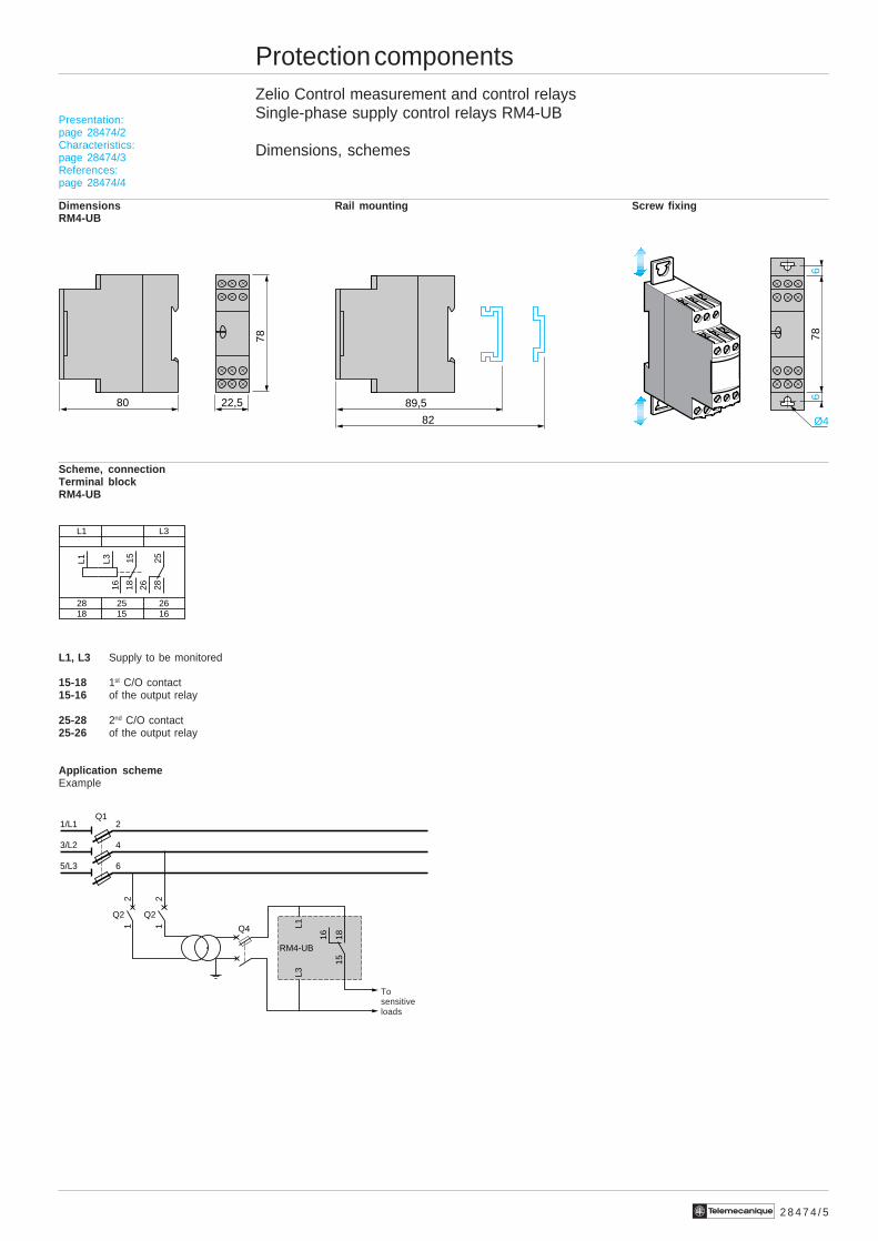
Dimensions, schemes
Dimensions Rail mounting Screw fixingRM4-UB
Scheme, connectionTerminal blockRM4-UB
L1, L3 Supply to be monitored
15-18 1st C/O contact15-16 of the output relay
25-28 2nd C/O contact25-26 of the output relay
Application schemeExample
Presentation:page 28474/2Characteristics:page 28474/3References:page 28474/4
80 22,5 89,5
82 Ø4
66
7878
L1 L3
18 15 1628 25 26
1815
16 2825
26
L1 L3
151816
Q2
12
Q2
12
Q11/L1 2
3/L2 4
5/L3 6
Q4
RM4-UB
L3L1
Tosensitiveloads
2 8 4 7 5 / 2 Te
Protection componentsZelio Control measurement and control relaysLiquid level control relays
Presentation
Functions
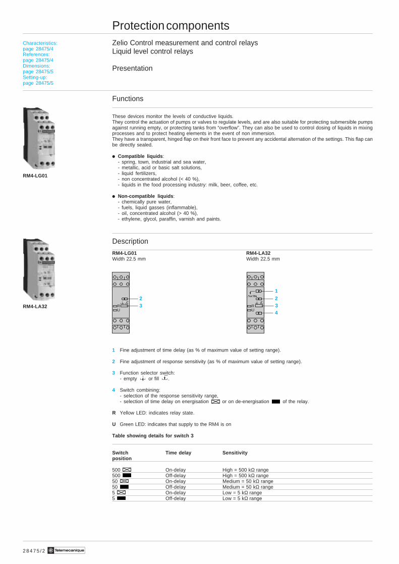
These devices monitor the levels of conductive liquids.They control the actuation of pumps or valves to regulate levels, and are also suitable for protecting submersible pumpsagainst running empty, or protecting tanks from “overflow”. They can also be used to control dosing of liquids in mixingprocesses and to protect heating elements in the event of non immersion.They have a transparent, hinged flap on their front face to prevent any accidental alternation of the settings. This flap canbe directly sealed.
i Compatible liquids :- spring, town, industrial and sea water,- metallic, acid or basic salt solutions,- liquid fertilizers,- non concentrated alcohol (< 40 %),- liquids in the food processing industry: milk, beer, coffee, etc.
i Non-compatible liquids :- chemically pure water,- fuels, liquid gasses (inflammable),- oil, concentrated alcohol (> 40 %),- ethylene, glycol, paraffin, varnish and paints.
Description
RM4-LG01 RM4-LA32Width 22.5 mm Width 22.5 mm
1 Fine adjustment of time delay (as % of maximum value of setting range).
2 Fine adjustment of response sensitivity (as % of maximum value of setting range).
3 Function selector switch:- empty or fill .
4 Switch combining:- selection of the response sensitivity range,- selection of time delay on energisation or on de-energisation of the relay.
R Yellow LED: indicates relay state.
U Green LED: indicates that supply to the RM4 is on
Table showing details for switch 3
Switch Time delay Sensitivityposition
500 On-delay High = 500 kΩ range500 Off-delay High = 500 kΩ range50 On-delay Medium = 50 kΩ range50 Off-delay Medium = 50 kΩ range5 On-delay Low = 5 kΩ range5 Off-delay Low = 5 kΩ range
RM4-LG01
23R
U
12
4RU
3RM4-LA32
Characteristics:page 28475/4References:page 28475/4Dimensions:page 28475/5Setting-up:page 28475/5
Te2 8 4 7 5 / 3
Protection componentsZelio Control measurement and control relaysLiquid level control relays
Presentation (continued)
Operating principle
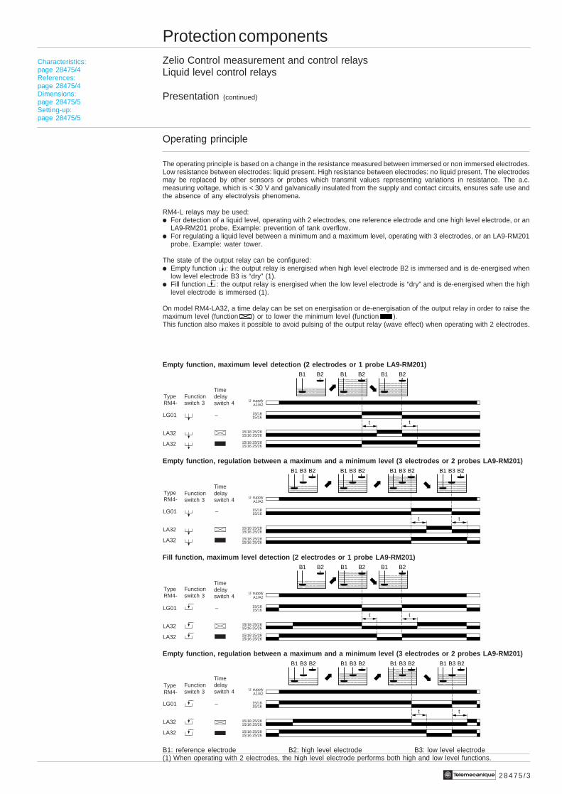
The operating principle is based on a change in the resistance measured between immersed or non immersed electrodes.Low resistance between electrodes: liquid present. High resistance between electrodes: no liquid present. The electrodesmay be replaced by other sensors or probes which transmit values representing variations in resistance. The a.c.measuring voltage, which is < 30 V and galvanically insulated from the supply and contact circuits, ensures safe use andthe absence of any electrolysis phenomena.
RM4-L relays may be used:i For detection of a liquid level, operating with 2 electrodes, one reference electrode and one high level electrode, or an
LA9-RM201 probe. Example: prevention of tank overflow.i For regulating a liquid level between a minimum and a maximum level, operating with 3 electrodes, or an LA9-RM201
probe. Example: water tower.
The state of the output relay can be configured:i Empty function : the output relay is energised when high level electrode B2 is immersed and is de-energised when
low level electrode B3 is “dry” (1).i Fill function : the output relay is energised when the low level electrode is “dry” and is de-energised when the high
level electrode is immersed (1).
On model RM4-LA32, a time delay can be set on energisation or de-energisation of the output relay in order to raise themaximum level (function ) or to lower the minimum level (function ).This function also makes it possible to avoid pulsing of the output relay (wave effect) when operating with 2 electrodes.
Empty function, maximum level detection (2 electrodes or 1 probe LA9-RM201)
Empty function, regulation between a maximum and a minimum level (3 electrodes or 2 probes LA9-RM201)
Fill function, maximum level detection (2 electrodes or 1 probe LA9-RM201)
Empty function, regulation between a maximum and a minimum level (3 electrodes or 2 probes LA9-RM201)
B1: reference electrode B2: high level electrode B3: low level electrode(1) When operating with 2 electrodes, the high level electrode performs both high and low level functions.
Characteristics:page 28475/4References:page 28475/4Dimensions:page 28475/5Setting-up:page 28475/5
t t
15/18 25/2815/16 25/26
15/18 25/2815/16 25/26
15/1815/16
B1 B3 B2B1 B3 B2B1 B3 B2B1 B3 B2
tt
15/18 25/2815/16 25/26
15/18 25/2815/16 25/26
15/1815/16
B1 B3 B2B1 B3 B2B1 B3 B2B1 B3 B2
tt
15/18 25/2815/16 25/26
15/18 25/2815/16 25/26
15/18
LA32
LA32
LG01
LA32
LA32
LG01 –
LA32
LA32
LG01 –
LA32
LA32
LG01 –
– 15/16
B1 B2B1 B2B1 B2
tt
15/18 25/2815/16 25/26
15/18 25/2815/16 25/26
15/1815/16
B1 B2B1 B2B1 B2
U supplyA1/A2
TypeRM4-
U supplyA1/A2
U supplyA1/A2
U supplyA1/A2
Functionswitch 3
Timedelayswitch 4
TypeRM4-
Functionswitch 3
Timedelayswitch 4
TypeRM4-
Functionswitch 3
Timedelayswitch 4
TypeRM4-
Functionswitch 3
Timedelayswitch 4
2 8 4 7 5 / 4 Te
RM4-LA32
LA9-RM201
RM4-LG01
Protection componentsZelio Control measurement and control relaysLiquid level control relays
Characteristics, references
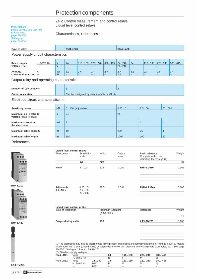
Type of relay RM4-LG01 RM4-LA32
Power supply circuit characteristics
Rated supply c 50/60 Hz V 24 110...130 220...240 380...415 24...240 24 110...130 220...240 380...415voltage (Un) a V – – – – 24...240 – – – –
Average c VA 1.9 2.6 2.4 2.9 2.7 3.1 2.7 2.6 3.4consumption at Un a W – – – – 2.4 – – – –
Output relay and operating characteristics
Number of C/O contacts 1 2
Output relay state Can be configured by switch: empty /fill
Electrode circuit characteristics (1)
Sensitivity scale k Ω 5…100 (adjustable) 0.25…5 2.5…50 25…500
Maximum a.c. electrode V 24 24voltage (peak to peak)
Maximum current in mA 1 1 1 1the electrodes
Maximum cable capacity nF 10 200 25 4
Maximum cable length m 100 1000 100 20
References
Liquid level control relaysTime delay Sensitivity Width Output Basic reference. Weight
scale relay Complete with codeindicating the voltage (2)
kΩ mm kg
None 5…100 22.5 1 C/O RM4-LG01i 0.165
Adjustable 0.25 ...5 22.5 2 C/O RM4-LA32ii 0.1650.1...10 s 2.5 ...50
25 ...500
Liquid level control probeType of installation Maximum operating Reference Weight
temperature°C kg
Suspended by cable 100 LA9-RM201 0.100
(1) The electrodes may also be incorporated in the probes. The probes are normally designed for fixing to a tank by meansof a bracket with a seal (closed tanks) or suspended by their own electrical connecting cable (boreholes, etc.). See page28475/5 “Setting-up” Probe LA9-RM201.(2) Standard supply voltagesRM4-LG01 Volts 24 110...130 220...240 380...415
c 50/60 Hz B F M QRM4-LA32 Volts 24...240 24 110...130 220...240 380...415
c 50/60 Hz MW B F M Qa MW – – – –
Presentation:pages 28475/2 and 28475/3Dimensions:page 28475/5Setting-up:page 28475/5
2 8 4 7 5 / 5Te
Protection componentsZelio Control measurement and control relaysLiquid level control relays
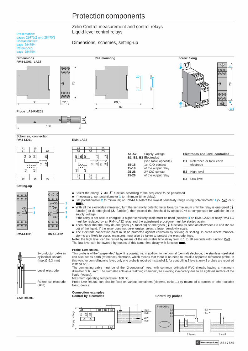
Dimensions, schemes, setting-up
Dimensions Rail mounting Screw fixingRM4-LG01, LA32
Probe LA9-RM201
Schemes, connectionRM4-LG01 RM4-LA32
A1-A2 Supply voltage Electrodes and level controlledB1, B2, B3 Electrodes
(see table opposite) B1 Reference or tank earth15-18 1st C/O contact electrode15-16 of the output relay25-28 2nd C/O contact B2 High level25-26 of the output relay
B3 Low level
Setting-up
i Select the empty /fill function according to the sequence to be performed.i If necessary, set potentiometer 1 to minimum (time delay).i Set potentiometer 2 to minimum; on RM4-LA select the lowest sensitivity range using potentiometer 4 (5 or 5
).i With all the electrodes immersed, turn the sensitivity potentiometer towards maximum until the relay is energised (
function) or de-energised ( function), then exceed the threshold by about 10 % to compensate for variation in thesupply voltage.If the relay is not able to energise, a higher sensitivity scale must be used (selector 4 on RM4-LA32) or relay RM4-LGmust be replaced by an RM4-LA32 relay and the adjustment procedure must be started again.
i Then check that the relay de-energises ( function) or energises ( function) as soon as electrodes B3 and B2 areout of the liquid. If the relay does not de-energise, select a lower sensitivity scale.
i The electrode connection point must be protected against corrosion by sticking or sealing. In areas where thunder-storms are likely to occur, measures must also be taken to protect the electrode lines.
Note: the high level can be raised by means of the adjustable time delay from 0.1 to 10 seconds with function .The low level can be lowered by means of this same time delay with function .
Probe LA9-RM201This probe is of the “suspended” type. It is coaxial, i.e. in addition to the normal (central) electrode, the stainless steel skirtcan also act as earth (reference) electrode, which means that there is no need to install a separate reference probe. Inthis way, for controlling one level, only one probe is required instead of 2; for controlling 2 levels, only 2 probes are requiredinstead of 3.The connecting cable must be of the “2-conductor” type, with common cylindrical PVC sheath, having a maximumdiameter of 6.3 mm. The skirt also acts as a ”calming chamber”, so avoiding inaccuracy due to an agitated surface of theliquid (waves).Maximum operating temperature: 100 °C.Probe LA9-RM201 can also be fixed on various containers (cisterns, tanks,...) by means of a bracket or other suitablefixing device.
Connection examplesControl by electrodes Control by probes
Presentation:pages 28475/2 and 28475/3Characteristics:page 28475/4References:page 28475/4
22,5
78
80 89,5
82 Ø4
66
78
150
16
B1 B2A1 15
B325
18 16 A228 26
1815
16
B3
26 2825B
2
B1
A2
A1
B1 B2A1 15
B3
18 16 A2
1815
16
B3
B2
B1
A2
A1
B3
B2
B1
A1 B2 B3B1
A2
B1B2
B3B2
B1
RM4-LG01
1 level
Lowlevel
Highlevel
Sup
ply
volta
ge
2 levels
12
4RU
323R
U
2-conductor cable incylindrical sheath(max.Ø 6.3 mm)
Reference electrode(skirt)
Level electrode
RM4-LG01 RM4-LA32
LA9-RM201
2 8 3 1 2 / 2 Te
R1
K2
K1 R2
L1L2L3N
RM3-PA1A1
A2
L+
–
Tt t t T
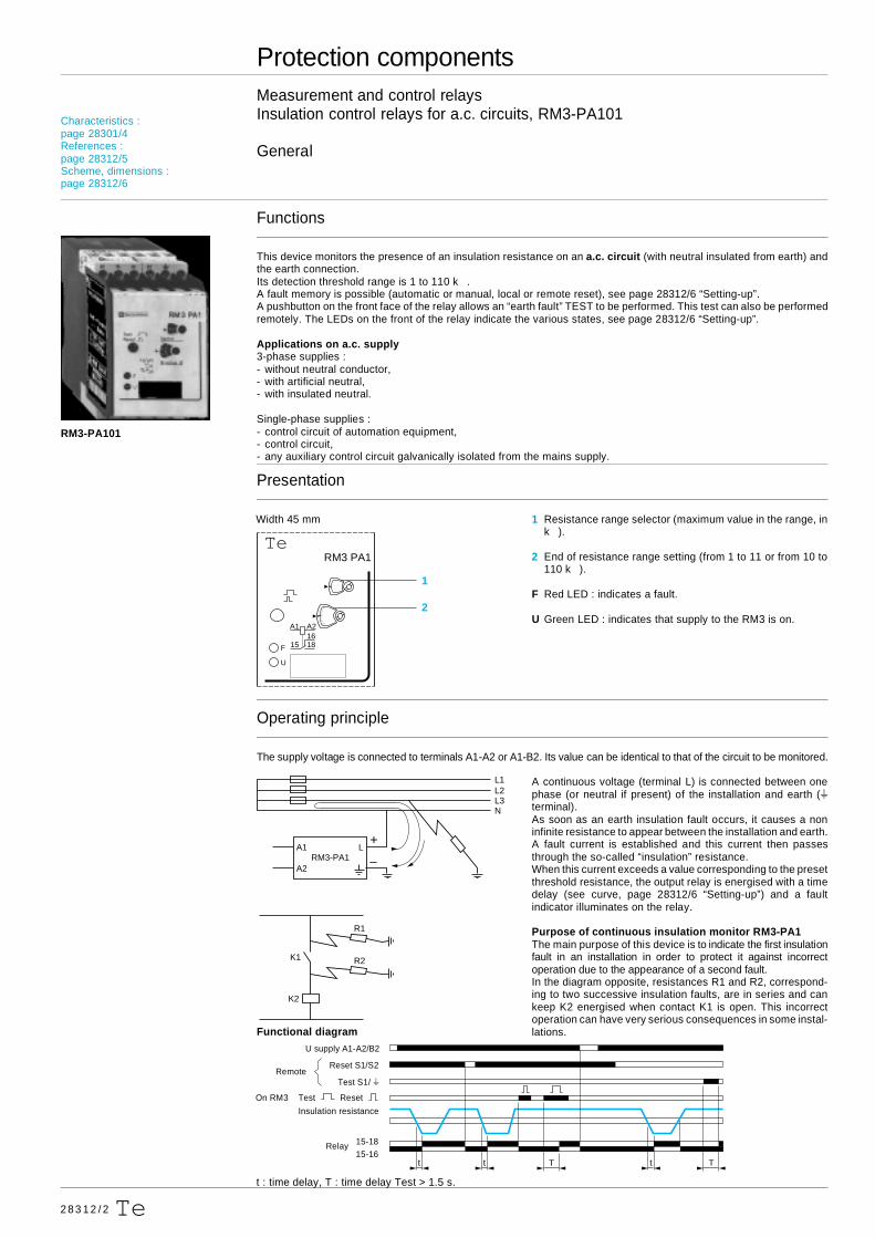
Protection componentsMeasurement and control relaysInsulation control relays for a.c. circuits, RM3-PA101
General
Functions
This device monitors the presence of an insulation resistance on an a.c. circuit (with neutral insulated from earth) andthe earth connection.Its detection threshold range is 1 to 110 k .A fault memory is possible (automatic or manual, local or remote reset), see page 28312/6 “Setting-up”.A pushbutton on the front face of the relay allows an “earth fault” TEST to be performed. This test can also be performedremotely. The LEDs on the front of the relay indicate the various states, see page 28312/6 “Setting-up”.
Applications on a.c. supply3-phase supplies :- without neutral conductor,- with artificial neutral,- with insulated neutral.
Single-phase supplies :- control circuit of automation equipment,- control circuit,- any auxiliary control circuit galvanically isolated from the mains supply.
Presentation
Width 45 mm 1 Resistance range selector (maximum value in the range, ink ).
2 End of resistance range setting (from 1 to 11 or from 10 to110 k ).
F Red LED : indicates a fault.
U Green LED : indicates that supply to the RM3 is on.
Operating principle
The supply voltage is connected to terminals A1-A2 or A1-B2. Its value can be identical to that of the circuit to be monitored.
A continuous voltage (terminal L) is connected between onephase (or neutral if present) of the installation and earth (sterminal).As soon as an earth insulation fault occurs, it causes a noninfinite resistance to appear between the installation and earth.A fault current is established and this current then passesthrough the so-called “insulation” resistance.When this current exceeds a value corresponding to the presetthreshold resistance, the output relay is energised with a timedelay (see curve, page 28312/6 “Setting-up”) and a faultindicator illuminates on the relay.
Purpose of continuous insulation monitor RM3-PA1The main purpose of this device is to indicate the first insulationfault in an installation in order to protect it against incorrectoperation due to the appearance of a second fault.In the diagram opposite, resistances R1 and R2, correspond-ing to two successive insulation faults, are in series and cankeep K2 energised when contact K1 is open. This incorrectoperation can have very serious consequences in some instal-lations.
t : time delay, T : time delay Test > 1.5 s.
RM3-PA101
Characteristics :page 28301/4References :page 28312/5Scheme, dimensions :page 28312/6
Functional diagram
On RM3 Test Reset
15-1815-16
U supply A1-A2/B2
Reset S1/S2
Test S1/ sRemote
Insulation resistance
Relay
15 1816A2A1
F
U
RM3 PA1Te
2
1
2 8 3 1 2 / 4 Te
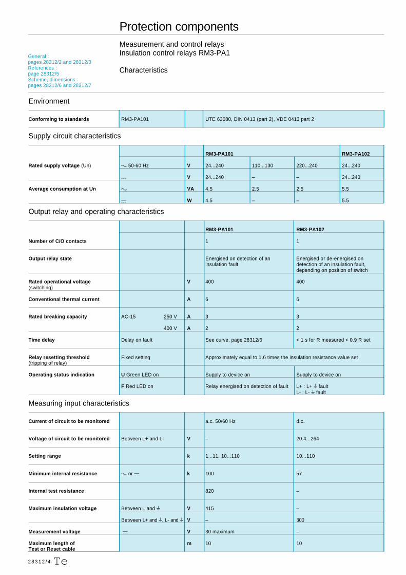
Protection componentsMeasurement and control relaysInsulation control relays RM3-PA1
Characteristics
Environment
Conforming to standards RM3-PA101 UTE 63080, DIN 0413 (part 2), VDE 0413 part 2
Supply circuit characteristics
RM3-PA101 RM3-PA102
Rated supply voltage (Un) c 50-60 Hz V 24...240 110...130 220...240 24...240
a V 24...240 – – 24...240
Average consumption at Un c VA 4.5 2.5 2.5 5.5
a W 4.5 – – 5.5
Output relay and operating characteristics
RM3-PA101 RM3-PA102
Number of C/O contacts 1 1
Output relay state Energised on detection of an Energised or de-energised oninsulation fault detection of an insulation fault,
depending on position of switch
Rated operational voltage V 400 400(switching)
Conventional thermal current A 6 6
Rated breaking capacity AC-15 250 V A 3 3
400 V A 2 2
Time delay Delay on fault See curve, page 28312/6 < 1 s for R measured < 0.9 R set
Relay resetting threshold Fixed setting Approximately equal to 1.6 times the insulation resistance value set(tripping of relay)
Operating status indication U Green LED on Supply to device on Supply to device on
F Red LED on Relay energised on detection of fault L+ : L+ s faultL- : L- s fault
Measuring input characteristics
Current of circuit to be monitored a.c. 50/60 Hz d.c.
Voltage of circuit to be monitored Between L+ and L- V – 20.4...264
Setting range k 1...11, 10...110 10...110
Minimum internal resistance c or a k 100 57
Internal test resistance 820 –
Maximum insulation voltage Between L and s V 415 –
Between L+ and s, L- and s V – 300
Measurement voltage a V 30 maximum –
Maximum length of m 10 10Test or Reset cable
General :pages 28312/2 and 28312/3References :page 28312/5Scheme, dimensions :pages 28312/6 and 28312/7
2 8 3 1 2 / 5Te
Protection componentsMeasurement and control relaysInsulation control relays RM3-PA1
References
Insulation control relays
Insulation Current of Basic reference. Weightmeasurement monitored Complete with code indicating
circuit control circuit voltage (1) kg
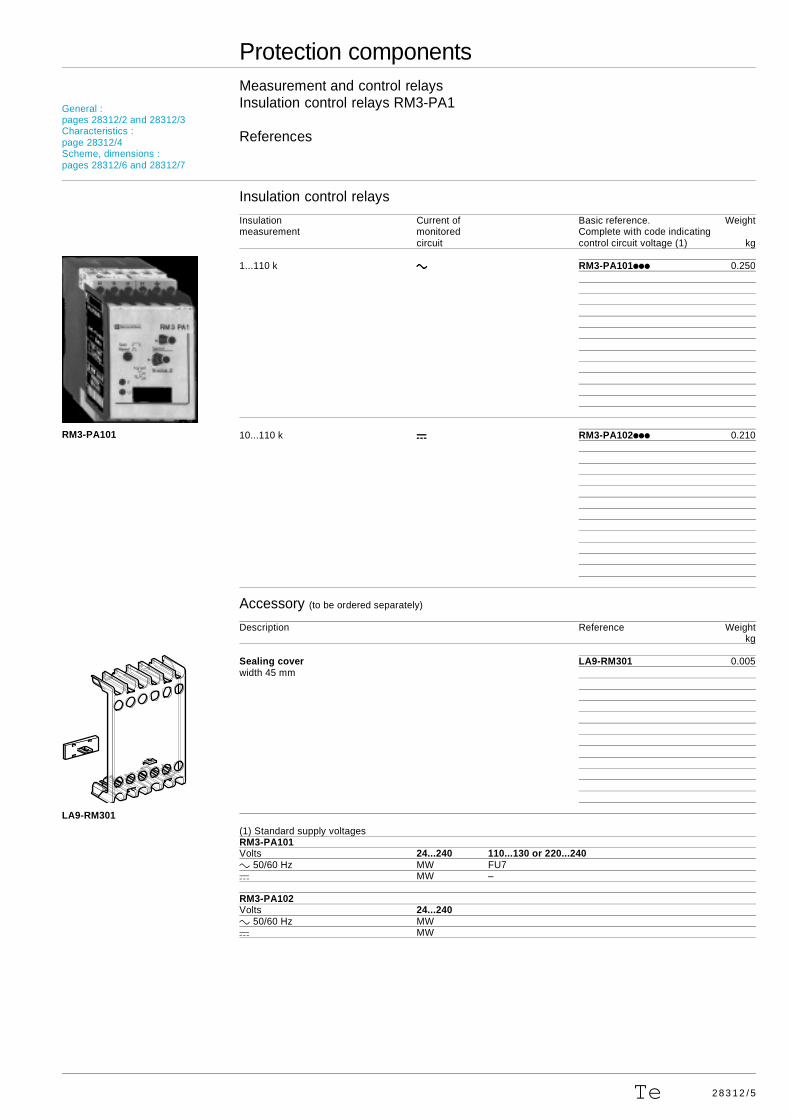
1...110 k cccc RM3-PA101iii 0.250
10...110 k aaaa RM3-PA102iii 0.210
Accessory (to be ordered separately)
Description Reference Weightkg
Sealing cover LA9-RM301 0.005width 45 mm
(1) Standard supply voltagesRM3-PA101Volts 24...240 110...130 or 220...240c 50/60 Hz MW FU7a MW –
RM3-PA102Volts 24...240c 50/60 Hz MWa MW
RM3-PA101
LA9-RM301
General :pages 28312/2 and 28312/3Characteristics :page 28312/4Scheme, dimensions :pages 28312/6 and 28312/7
2 8 3 1 2 / 6 Te
0,1 1 10Rim
100kΩ
1,5
1
0,5
2
2,5tA
3
Sec 1 2 4 6 10 20Ris
40 60 100kΩ
c A2
A1 L
RM3-PA1 s
L1L2L3
SP
SP
c A2
A1 L
RM3-PA1 s
L1L2L3N
18
15
16
L
A1 15 S1 sS2
16 18 L A2B2
R < s
SP
22
0…
24
0 V
c/a
(FU
)
11
0…
13
0 V
c/a
(FU
)
c A2
A1 L
RM3-PA1 s
L1L2L3N
SP
c A2
A1 L
RM3-PA1 s
L1L2L3
SP
Protection componentsMeasurement and control relaysInsulation control relays for a.c. circuits, RM3-PA101
Scheme, dimensions, setting-up
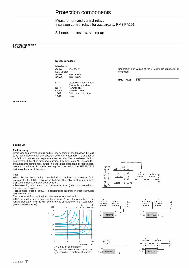
Scheme, connectionRM3-PA101
Supply voltages :
Mixed c or aA1-A2 24...240 VDual voltage cA1-B2 110...130 VA1-A2 220...240 V
L, s Insulation measurement(see table opposite)
S1- s Remote TESTS1-S2 Remote Reset15-18 C/O contact of output15-16 relay
Dimensions
Setting-up
Fault memoryShort-circuiting of terminals S1 and S2 (see scheme opposite) allows the faultto be memorised as soon as it appears, even if only fleetingly. The duration ofthe fault must exceed the response time of the relay (see curve below) for it tobe detected. If this short-circuiting is achieved by means of a N/C pushbutton,this acts as the remote reset button (if the fault has disappeared). Manual localresetting is achieved by briefly pressing (less than 0.5 s) the RESET/TESTbutton on the front of the relay.
TestWhen the installation being controlled does not have an insulation fault,pressing the RESET/TEST button on the front of the relay and holding for morethan 1.5 s causes 2 simultaneous actions :- the measuring input terminal not connected to earth (L) is disconnected fromthe line being controlled,- a resistance (internal) of 820 is connected to this input in order to simulatean insulation fault.The relay must then react in the same way as for a real fault.A N/O pushbutton may be connected to terminals S1 and s which will act as theremote test button and this will have the same effect as the built-in test button(see scheme opposite).
tA = Delay on energisationRim = Insulation resistance measuredRis = Insulation resistance threshold
Connection and values of the 2 resistance ranges to becontrolled
RM3-PA101 L to
2 8 3 1 2 / 7Te
Protection componentsMeasurement and control relaysInsulation control relays for d.c. circuits, RM3-PA102
Scheme, dimensions, setting-up
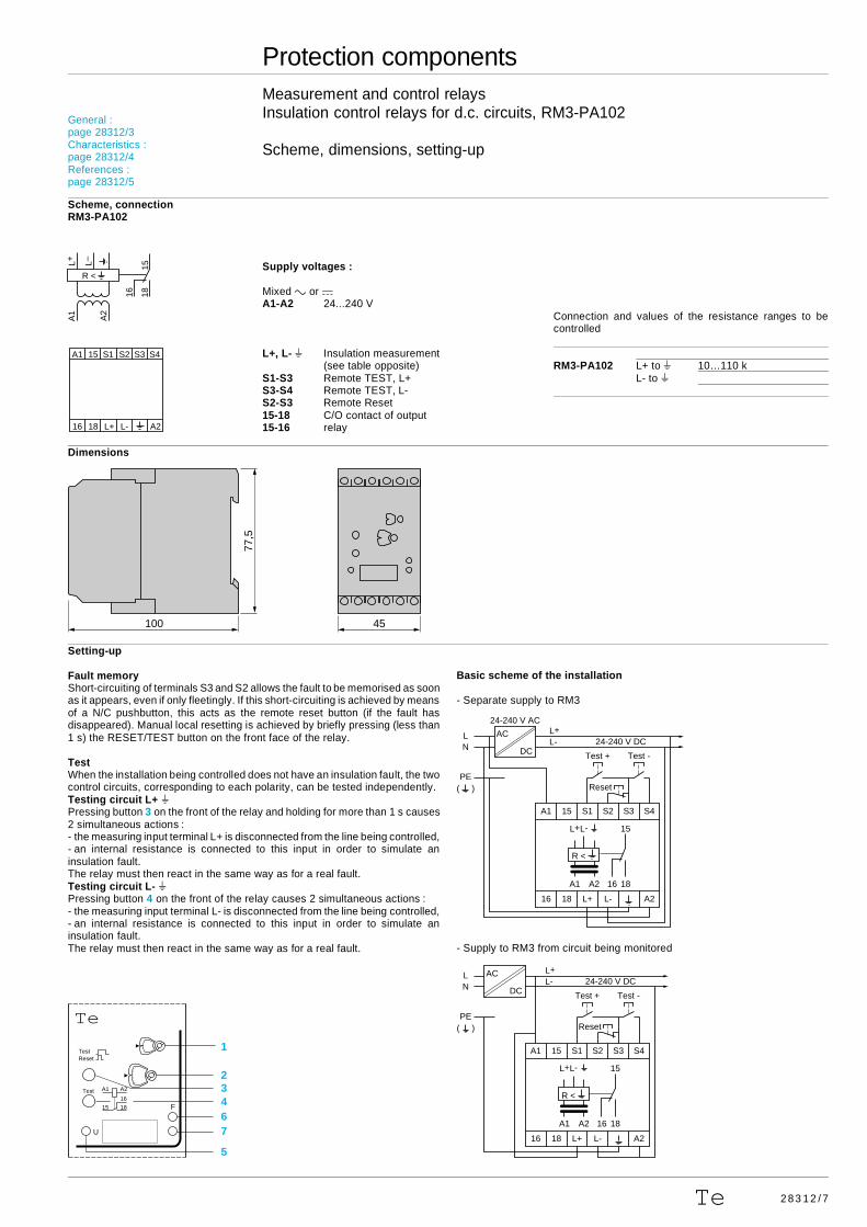
Scheme, connectionRM3-PA102
Supply voltages :
Mixed c or aA1-A2 24...240 V
L+, L- s Insulation measurement(see table opposite)
S1-S3 Remote TEST, L+S3-S4 Remote TEST, L-S2-S3 Remote Reset15-18 C/O contact of output15-16 relay
Dimensions
Setting-up
Fault memoryShort-circuiting of terminals S3 and S2 allows the fault to be memorised as soonas it appears, even if only fleetingly. If this short-circuiting is achieved by meansof a N/C pushbutton, this acts as the remote reset button (if the fault hasdisappeared). Manual local resetting is achieved by briefly pressing (less than1 s) the RESET/TEST button on the front face of the relay.
TestWhen the installation being controlled does not have an insulation fault, the twocontrol circuits, corresponding to each polarity, can be tested independently.Testing circuit L+ sPressing button 3 on the front of the relay and holding for more than 1 s causes2 simultaneous actions :- the measuring input terminal L+ is disconnected from the line being controlled,- an internal resistance is connected to this input in order to simulate aninsulation fault.The relay must then react in the same way as for a real fault.Testing circuit L- sPressing button 4 on the front of the relay causes 2 simultaneous actions :- the measuring input terminal L- is disconnected from the line being controlled,- an internal resistance is connected to this input in order to simulate aninsulation fault.The relay must then react in the same way as for a real fault.
Connection and values of the resistance ranges to becontrolled
RM3-PA102 L+ to s 10…110 kL- to s
Basic scheme of the installation
- Separate supply to RM3
- Supply to RM3 from circuit being monitored
1815
16
A2
L–L+A
1
R <
A1 15 S1 S2 S3 S4
16 18 A2L-L+
L L+ L-
N
PE( )
24-240 V AC
24-240 V DCAC
DC
A1 A2 18
15L+L-
16
R <
Reset
Test + Test -
A1 15 S1 S2 S3 S4
16 18 L+ L- A2
L L+ L-
N
PE( )
24-240 V DCAC
DC
A1 A2 18
15L+L-
16
R <
Reset
Test + Test -
A1 15 S1 S2 S3 S4
16 18 L+ L- A2
15 18
16
A2A1
U
F
2
67
43
5
1TestReset
Test
Te
General :page 28312/3Characteristics :page 28312/4References :page 28312/5
45
77,5
100
28313/2 Te
15 1816A2A1
25 28 26
R
U
RM3 EA1Te
2
1
Protection componentsMeasurement and control relaysSensitive contact protection relays RM3-EA1
General
Functions
This device relays, protects and amplifies a low level “Discrete” output. It may be used with or without memory function.The adjustable time delay from 0.05 to 30 s avoids oscillations of the relay in the event of interference or bouncing of thecontact to be protected.It can be controlled by a mechanical contact or by a 3-wire solid state switch (see examples, page 28313/5 “Setting-up”).
Applications :- protection,- ensuring reliability,- amplification of low level outputs on measuring devices, sensors, probes etc.
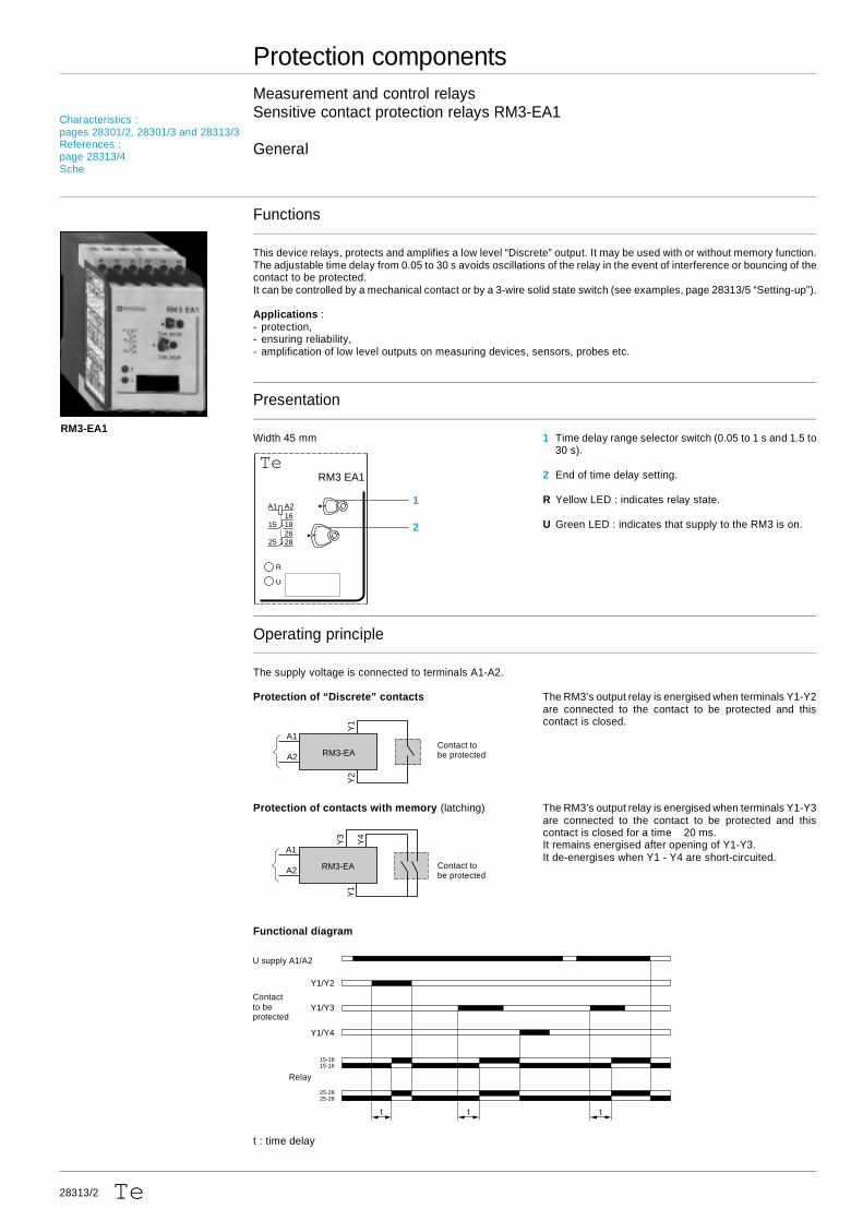
Presentation
Width 45 mm 1 Time delay range selector switch (0.05 to 1 s and 1.5 to30 s).
2 End of time delay setting.
R Yellow LED : indicates relay state.
U Green LED : indicates that supply to the RM3 is on.
Operating principle
The supply voltage is connected to terminals A1-A2.
Protection of “Discrete” contacts The RM3’s output relay is energised when terminals Y1-Y2are connected to the contact to be protected and thiscontact is closed.
Protection of contacts with memory (latching) The RM3’s output relay is energised when terminals Y1-Y3are connected to the contact to be protected and thiscontact is closed for a time 20 ms.It remains energised after opening of Y1-Y3.It de-energises when Y1 - Y4 are short-circuited.
Functional diagram
t : time delay
U supply A1/A2
15-1815-16
t t t
25-2825-26
Y1/Y4
Y1/Y3
Y1/Y2
Relay
Contact tobe protected
Contact tobe protected
A1
RM3-EA
Y4
Y3
Y1
A2
A1
RM3-EA
Y1
Y2
A2
RM3-EA1
Contactto beprotected
Characteristics :pages 28301/2, 28301/3 and 28313/3References :page 28313/4Sche
2 8 3 1 3 / 3Te
General :page 28313/2References :page 28313/4Scheme, dimensions :page 28313/5
Protection componentsMeasurement and control relaysSensitive contact protection relays RM3-EA1
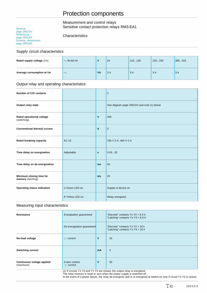
Characteristics
Supply circuit characteristics
Rated supply voltage (Un) c 50-60 Hz V 24 110...130 220...240 380...415
Average consumption at Un c VA 3.4 3.4 3.4 3.4
Output relay and operating characteristics
Number of C/O contacts 2
Output relay state See diagram page 28313/2 and note (1) below
Rated operational voltage V 400(switching)
Conventional thermal current A 5
Rated breaking capacity AC-15 230 V-3 A, 400 V-2 A
Time delay on energisation Adjustable s 0.05...30
Time delay on de-energisation ms 50
Minimum closing time for ms 20memory (latching)
Operating status indication U Green LED on Supply to device on
R Yellow LED on Relay energised
Measuring input characteristics
Resistance Energisation guaranteed “Discrete” contacts Y1-Y2 < 6.5 k“Latching” contacts Y1-Y3 < 6.5 k
De-energisation guaranteed “Discrete” contacts Y1-Y2 > 19 k“Latching” contacts Y1-Y4 < 16 k
No-load voltage a current V 10
Switching current mA 3
Continuous voltage applied 3-wire control, V 30(maximum) a current
(1) If circuits Y1-Y3 and Y1-Y4 are closed, the output relay is energised.The relay memory is reset to zero when the power supply is switched off.In the event of a power failure, the relay de-energises and is re-energised at switch-on only if circuit Y1-Y3 is closed.
2 8 3 1 3 / 4 Te
Protection componentsMeasurement and control relaysSensitive contact protection relays RM3-EA1
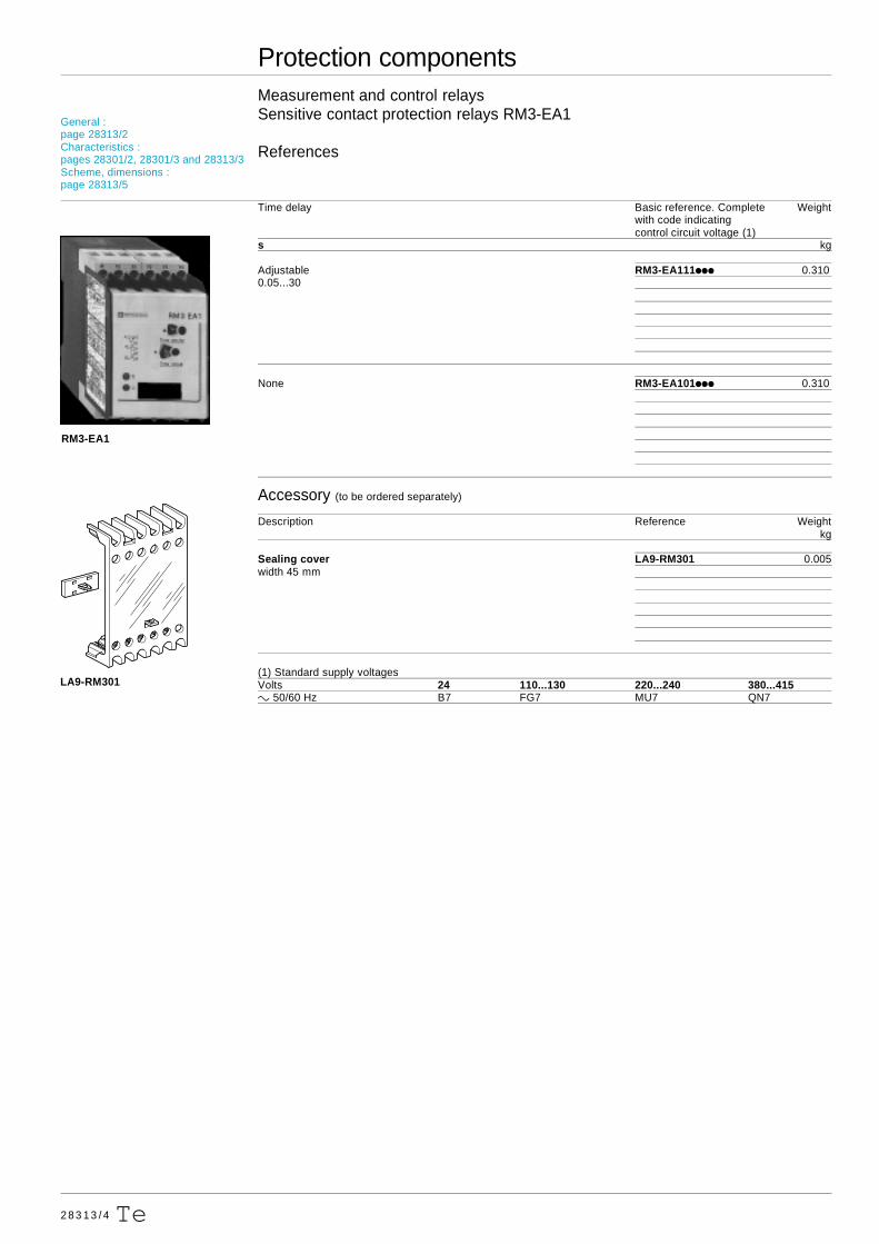
References
Time delay Basic reference. Complete Weightwith code indicatingcontrol circuit voltage (1)
s kg
Adjustable RM3-EA111iii 0.3100.05...30
None RM3-EA101iii 0.310
Accessory (to be ordered separately)
Description Reference Weightkg
Sealing cover LA9-RM301 0.005width 45 mm
(1) Standard supply voltagesVolts 24 110...130 220...240 380...415c 50/60 Hz B7 FG7 MU7 QN7
RM3-EA1
LA9-RM301
General :page 28313/2Characteristics :pages 28301/2, 28301/3 and 28313/3Scheme, dimensions :page 28313/5
28313/5Te
Protection componentsMeasurement and control relaysSensitive contact protection relays RM3-EA1
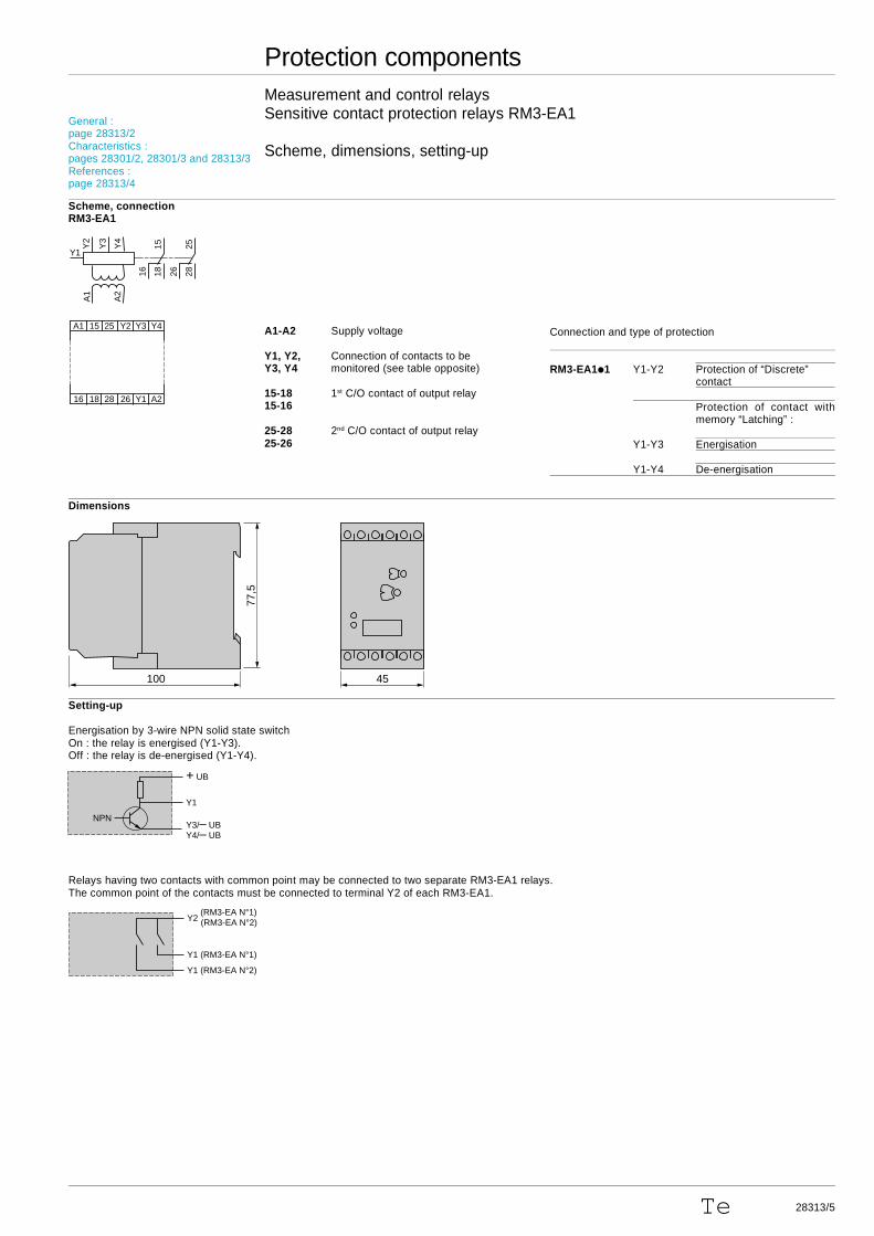
Scheme, dimensions, setting-up
Scheme, connectionRM3-EA1
A1-A2 Supply voltage
Y1, Y2, Connection of contacts to beY3, Y4 monitored (see table opposite)
15-18 1st C/O contact of output relay15-16
25-28 2nd C/O contact of output relay25-26
Dimensions
Setting-up
Energisation by 3-wire NPN solid state switchOn : the relay is energised (Y1-Y3).Off : the relay is de-energised (Y1-Y4).
Relays having two contacts with common point may be connected to two separate RM3-EA1 relays.The common point of the contacts must be connected to terminal Y2 of each RM3-EA1.
Connection and type of protection
RM3-EA1i1 Y1-Y2 Protection of “Discrete”contact
Protection of contact withmemory “Latching” :
Y1-Y3 Energisation
Y1-Y4 De-energisation
NPN
+ UB
Y1
Y3/– UBY4/– UB
1815
16
Y4
2825
26
Y3
Y2
A2
A1
Y1
A1 15 25 Y3 Y4Y2
16 18 28 Y1 A226
General :page 28313/2Characteristics :pages 28301/2, 28301/3 and 28313/3References :page 28313/4
45
77,5
100
Y2 (RM3-EA N°1)(RM3-EA N°2)
Y1 (RM3-EA N°2)
Y1 (RM3-EA N°1)