
YOKOGAWA TRANSMITTERS9(EJX110A, EJX120A, EJX130A, EJX310A, EJX430A, and EJX440A)
78
User’s Manual EJX110A, EJX120A, EJX130A, EJX310A, EJX430A, and EJX440A Differential Pressure and Pressure T ransmitters IM 01C25B01-01E IM 01C25B01-01E 11th Edition
-
Upload
joshuaisaac -
Category
Documents
-
view
219 -
download
0
Transcript of YOKOGAWA TRANSMITTERS9(EJX110A, EJX120A, EJX130A, EJX310A, EJX430A, and EJX440A)

8/9/2019 YOKOGAWA TRANSMITTERS9(EJX110A, EJX120A, EJX130A, EJX310A, EJX430A, and EJX440A)
http://slidepdf.com/reader/full/yokogawa-transmitters9ejx110a-ejx120a-ejx130a-ejx310a-ejx430a-and-ejx440a 1/78
User’sManual
EJX110A, EJX120A, EJX130A,EJX310A, EJX430A, and EJX440ADifferential Pressure andPressure Transmitters
IM 01C25B01-01E
IM 01C25B01-01E11th Edition

8/9/2019 YOKOGAWA TRANSMITTERS9(EJX110A, EJX120A, EJX130A, EJX310A, EJX430A, and EJX440A)
http://slidepdf.com/reader/full/yokogawa-transmitters9ejx110a-ejx120a-ejx130a-ejx310a-ejx430a-and-ejx440a 2/78
i
IM 01C25B01-01E
EJX110A, EJX120A, EJX130A,
EJX310A, EJX430A, and EJX440A
Differential Pressure and Pressure Transmitters
IM 01C25B01-01E 11th Edition
11th Edition: Mar. 2012 (YK) All Rights Reserved, Copyright © 2004, Yokogawa Electric Corporation
Contents
1. Introduction ............................................................................................... 1-1
Regarding This Manual ................................................................................................1-1
1.1 Safe Use of This Product .................................................................................1-2
1.2 Warranty .............................................................................................................1-3
1.3 ATEX Documentation .......................................................................................1-4
2. Handling Cautions .................................................................................... 2-1
2.1 Model and Specications Check .....................................................................2-1
2.2 Unpacking ..........................................................................................................2-1
2.3 Storage ...............................................................................................................2-1
2.4 Selecting the Installation Location ................................................................2-2
2.5 Pressure Connection ........................................................................................2-2
2.6 Waterproong of Cable Conduit Connections ..............................................2-2
2.7 Restrictions on Use of Radio Transceivers ...................................................2-2
2.8 Insulation Resistance and Dielectric Strength Test ......................................2-2
2.9 Installation of an Explosion-Protected Instrument .......................................2-3
2.9.1 FM Approval .......................................................................................2-4
2.9.2 CSA Certication ................................................................................2-5
2.9.3 CENELEC ATEX (KEMA) Certication ..............................................2-7
2.9.4 IECEx Certication ........................................................................... 2-11
2.10 EMC Conformity Standards ...........................................................................2-12
2.11 Pressure Equipment Directive (PED) ...........................................................2-12
2.12 Low Voltage Directive .....................................................................................2-13
3. Component Names .................................................................................. 3-1
4. Installation ................................................................................................. 4-14.1 Precautions .......................................................................................................4-1
4.2 Mounting ...........................................................................................................4-1
4.3 Changing the Process Connection .................................................................4-2
4.4 Swapping the High/Low-pressure Side Connection .....................................4-3
4.4.1 Rotating Pressure-detector Section 180° .........................................4-3
4.4.2 Using the Communicator ...................................................................4-3
4.5 Rotating Transmitter Section ...........................................................................4-4
4.6 Changing the Direction of Integral Indicator .................................................4-4

8/9/2019 YOKOGAWA TRANSMITTERS9(EJX110A, EJX120A, EJX130A, EJX310A, EJX430A, and EJX440A)
http://slidepdf.com/reader/full/yokogawa-transmitters9ejx110a-ejx120a-ejx130a-ejx310a-ejx430a-and-ejx440a 3/78
ii
IM 01C25B01-01E
5. Installing Impulse Piping ......................................................................... 5-1
5.1 Impulse Piping Installation Precautions ........................................................5-1
5.1.1 Connecting Impulse Piping to a Transmitter ......................................5-1
5.1.2 Routing the Impulse Piping ................................................................5-3
5.2 Impulse Piping Connection Examples ...........................................................5-4
6. Wiring ......................................................................................................... 6-16.1 Wiring Precautions ...........................................................................................6-1
6.2 Selecting the Wiring Materials .........................................................................6-1
6.3 Connections of External Wiring to Terminal Box ..........................................6-1
6.3.1 Power Supply Wiring Connection ......................................................6-1
6.3.2 External Indicator Connection............................................................6-1
6.3.3 Communicator Connection ................................................................6-1
6.3.4 Check Meter Connection ...................................................................6-2
6.3.5 Status Output Connection ..................................................................6-2
6.4 Wiring .................................................................................................................6-2
6.4.1 Loop Conguration ............................................................................6-2
6.4.2 Wiring Installation ...............................................................................6-2
6.5 Grounding ..........................................................................................................6-3
6.6 Power Supply Voltage and Load Resistance .................................................6-3
7. Operation ................................................................................................... 7-1
7.1 Preparation for Starting Operation .................................................................7-1
7.2 Zero Point Adjustment .....................................................................................7-2
7.2.1 Adjusting Zero Point for Differential Pressure Transmitters .............. 7-3
7.2.2 Adjusting Zero Point for Gauge/Absolute Pressure Transmitters .... 7-3
7.3 Starting Operation ............................................................................................7-3
7.4 Shutting Down the Transmitter .......................................................................7-4
7.5 Venting or Draining Transmitter Pressure-detector Section .......................7-4
7.5.1 Draining Condensate .........................................................................7-4
7.5.2 Venting Gas........................................................................................7-5
7.6 Setting the Range Using the Range-setting Switch ......................................7-5
8. Maintenance .............................................................................................. 8-1
8.1 Overview ............................................................................................................8-1
8.2 Calibration Instruments Selection ..................................................................8-1
8.3 Calibration .........................................................................................................8-1
8.4 Disassembly and Reassembly ........................................................................8-3
8.4.1 Replacing the Integral Indicator .........................................................8-3
8.4.2 Replacing the CPU Board Assembly .................................................8-4
8.4.3 Cleaning and Replacing the Capsule Assembly ...............................8-4
8.4.4 Replacing the Process Connector Gaskets .......................................8-6

8/9/2019 YOKOGAWA TRANSMITTERS9(EJX110A, EJX120A, EJX130A, EJX310A, EJX430A, and EJX440A)
http://slidepdf.com/reader/full/yokogawa-transmitters9ejx110a-ejx120a-ejx130a-ejx310a-ejx430a-and-ejx440a 4/78
iii
IM 01C25B01-01E
8.5 Troubleshooting ................................................................................................8-6
8.5.1 Basic Troubleshooting .......................................................................8-6
8.5.2 Troubleshooting Flowcharts...............................................................8-7
8.5.3 Alarms and Countermeasures ...........................................................8-9
9. General Specications ............................................................................ 9-1
9.1 Standard Specications ...................................................................................9-19.2 Model and Sufx Codes ...................................................................................9-5
9.3 Optional Specications .................................................................................9-12
9.4 Dimensions ......................................................................................................9-15
Revision Information
When using the EJX in a Safety Instrumented Systems(SIS) application,refer to Appendix A in either IM 01C25T01-01E for the HART protocol orIM 01C25T03-01E for the BRAIN protocol.

8/9/2019 YOKOGAWA TRANSMITTERS9(EJX110A, EJX120A, EJX130A, EJX310A, EJX430A, and EJX440A)
http://slidepdf.com/reader/full/yokogawa-transmitters9ejx110a-ejx120a-ejx130a-ejx310a-ejx430a-and-ejx440a 5/78
<1. Introduction> 1-1
IM 01C25B01-01E
1. Introduction
Thank you for purchasing the DPharp EJX
Differential Pressure and pressure transmitter.
Your EJX Pressure Transmitter was precisely
calibrated at the factory before shipment. To ensureboth safety and efciency, please read this manual
carefully before you operate the instrument.
NOTE
This manual describes the hardware
congurations of EJX series transmitters. For
information on the software conguration and
operation, please refer to either
IM 01C25T03-01E for the EJX series BRAIN
communication type, or IM 01C25T01-01E/
IM 01C25T01-06EN for the EJX series HART
communication type.
For FOUNDATION Fieldbus protocol type,
please refer to IM 01C25T02-01E.
To ensure correct use of this instrument, read
both the hardware and software manuals
thoroughly before use.
WARNING
When using the EJX in a Safety Instrumented
Systems (SIS) application, refer to Appendix 1 in
either IM 01C25T01-01E/IM 01C25T01-06EN for
the HART protocol or IM 01C25T03-01E for the
BRAIN protocol. The instructions and procedures
in this section must be strictly followed in order to
maintain the transmitter for this safety level.
NOTE
This manual covers the EJX110A, EJX120Aand EJX130A differential pressure transmitter,
EJX430A and EJX440A gauge pressure
transmitter and EJX310A absolute pressure
transmitter whose style codes are as described
in the following table.
Unless otherwise stated, the illustrations in
this manual are of the EJX110A differential
pressure transmitter. Users of the other models
should bear in mind that certain features of their
instrument will differ from those shown in the
illustrations of the EJX110A.
Model Style code
EJX110A S3
EJX120A S1
EJX130A S2
EJX310A S2
EJX430A S2
EJX440A S2
Regarding This Manual
• This manual should be provided to the end
user.
• The contents of this manual are subject to
change without prior notice.
• All rights reserved. No part of this manual maybe reproduced in any form without Yokogawa’s
written permission.
• Yokogawa makes no warranty of any kind with
regard to this manual, including, but not limited
to, implied warranty of merchantability and
tness for a particular purpose.
• If any question arises or errors are found, or if
any information is missing from this manual,
please inform the nearest Yokogawa sales
ofce.
• The specications covered by this manual are
limited to those for the standard type under the
specied model number break-down and do not
cover custom-made instruments.
• Please note that changes in the specications,
construction, or component parts of the
instrument may not immediately be reected
in this manual at the time of change, provided
that postponement of revisions will not cause
difculty to the user from a functional or
performance standpoint.• Yokogawa assumes no responsibilities for this
product except as stated in the warranty.
• If the customer or any third party is harmed by
the use of this product, Yokogawa assumes
no responsibility for any such harm owing to
any defects in the product which were not
predictable, or for any indirect damages.
• The following safety symbols are used in this
manual:

8/9/2019 YOKOGAWA TRANSMITTERS9(EJX110A, EJX120A, EJX130A, EJX310A, EJX430A, and EJX440A)
http://slidepdf.com/reader/full/yokogawa-transmitters9ejx110a-ejx120a-ejx130a-ejx310a-ejx430a-and-ejx440a 6/78
<1. Introduction> 1-2
IM 01C25B01-01E
WARNING
Indicates a potentially hazardous situation which,if not avoided, could result in death or seriousinjury.
CAUTION
Indicates a potentially hazardous situation which,if not avoided, may result in minor or moderateinjury. It may also be used to alert against unsafepractices.
IMPORTANT
Indicates that operating the hardware or softwarein this manner may damage it or lead to systemfailure.
NOTE
Draws attention to information essential forunderstanding the operation and features.
Direct current
1.1 Safe Use of This Product
For the safety of the operator and to protect theinstrument and the system, please be sure to followthis manual’s safety instructions when handling thisinstrument. If these instructions are not heeded,the protection provided by this instrument may be
impaired. In this case, Yokogawa cannot guaranteethat the instrument can be safely operated. Pleasepay special attention to the following points:
(a) Installation
• This instrument may only be installed by anengineer or technician who has an expertknowledge of this device. Operators are notallowed to carry out installation unless theymeet this condition.
• With high process temperatures, care must
be taken not to burn yourself by touching theinstrument or its casing.
• Never loosen the process connector nuts whenthe instrument is installed in a process. This canlead to a sudden, explosive release of processuids.
• When draining condensate from the pressuredetector section, take appropriate precautionsto prevent the inhalation of harmful vapors andthe contact of toxic process uids with the skinor eyes.
• When removing the instrument from ahazardous process, avoid contact with the uidand the interior of the meter.
• All installation shall comply with local installationrequirements and the local electrical code.
(b) Wiring
• The instrument must be installed by anengineer or technician who has an expertknowledge of this instrument. Operators are not
permitted to carry out wiring unless they meetthis condition.
• Before connecting the power cables, pleaseconrm that there is no current owing throughthe cables and that the power supply to theinstrument is switched off.

8/9/2019 YOKOGAWA TRANSMITTERS9(EJX110A, EJX120A, EJX130A, EJX310A, EJX430A, and EJX440A)
http://slidepdf.com/reader/full/yokogawa-transmitters9ejx110a-ejx120a-ejx130a-ejx310a-ejx430a-and-ejx440a 7/78
<1. Introduction> 1-3
IM 01C25B01-01E
(c) Operation
• Wait 5 min. after the power is turned off, beforeopening the covers.
(d) Maintenance
• Please carry out only the maintenance
procedures described in this manual. If yourequire further assistance, please contact thenearest Yokogawa ofce.
• Care should be taken to prevent the build up ofdust or other materials on the display glass andthe name plate. To clean these surfaces, use asoft, dry cloth.
(e) Explosion Protected Type Instrument
• Users of explosion proof instruments shouldrefer rst to section 2.9 (Installation of an
Explosion Protected Instrument) of this manual.• The use of this instrument is restricted to those
who have received appropriate training in thedevice.
• Take care not to create sparks when accessingthe instrument or peripheral devices in ahazardous location.
(f) Modication
• Yokogawa will not be liable for malfunctions ordamage resulting from any modication madeto this instrument by the customer.
1.2 Warranty
• The warranty shall cover the period noted onthe quotation presented to the purchaser at thetime of purchase. Problems occurring duringthe warranty period shall basically be repairedfree of charge.
• If any problems are experienced with thisinstrument, the customer should contact theYokogawa representative from which thisinstrument was purchased or the nearestYokogawa ofce.
• If a problem arises with this instrument,please inform us of the nature of the problemand the circumstances under which itdeveloped, including the model specicationand serial number. Any diagrams, data andother information you can include in your
communication will also be helpful.• The party responsible for the cost of xing the
problem shall be determined by Yokogawafollowing an investigation conducted byYokogawa.
• The purchaser shall bear the responsibility forrepair costs, even during the warranty period, ifthe malfunction is due to:
- Improper and/or inadequate maintenance by
the purchaser.- Malfunction or damage due to a failureto handle, use, or store the instrument inaccordance with the design specications.
- Use of the product in question in a locationnot conforming to the standards specied byYokogawa, or due to improper maintenanceof the installation location.
- Failure or damage due to modication orrepair by any party except Yokogawa or anapproved representative of Yokogawa.
- Malfunction or damage from improper
relocation of the product in question afterdelivery.
- Reason of force majeure such as res,earthquakes, storms/oods, thunder/lightening, or other natural disasters, ordisturbances, riots, warfare, or radioactivecontamination.

8/9/2019 YOKOGAWA TRANSMITTERS9(EJX110A, EJX120A, EJX130A, EJX310A, EJX430A, and EJX440A)
http://slidepdf.com/reader/full/yokogawa-transmitters9ejx110a-ejx120a-ejx130a-ejx310a-ejx430a-and-ejx440a 8/78
<1. Introduction> 1-4
IM 01C25B01-01E
1.3 ATEX Documentation
This is only applicable to the countries in European Union.
GB
DK
I
E
NL
SF
P
F
D
S
LT
LV
PL
EST
SLO
H
BG
RO
M
CZ
SK
GR

8/9/2019 YOKOGAWA TRANSMITTERS9(EJX110A, EJX120A, EJX130A, EJX310A, EJX430A, and EJX440A)
http://slidepdf.com/reader/full/yokogawa-transmitters9ejx110a-ejx120a-ejx130a-ejx310a-ejx430a-and-ejx440a 9/78
<2. Handling Cautions> 2-1
IM 01C25B01-01E
2. Handling Cautions
This chapter provides important information on howto handle the transmitter. Read this carefully beforeusing the transmitter.
EJX Series transmitters are thoroughly tested at thefactory before shipment. When taking delivery of aninstrument, visually check them to make sure thatno damage occurred during shipment.
Also check that all transmitter mounting hardwareshown in gure 2.1 is included. If the transmitteris ordered without the mounting bracket and theprocess connector, the transmitter mountinghardware will not be included. After checking thetransmitter, carefully repack it in its box and keep itthere until you are ready to install it.
Bolt
Process connector (Note 1)
Process connector Gasket
U-bolt nut
U-bolt
Mounting bracket(L type)
Transmitter mounting bolt
Mounting bracket
(Flat type)
F0201.ai
Figure 2.1 Transmitter Mounting Hardware
2.1 Model and Specications
Check
The model name and specications are written onthe name plate attached to the case.
F0202.ai
Figure 2.2 Name Plate (EJX110A)
2.2 Unpacking
Keep the transmitter in its original packaging toprevent it from being damaged during shipment.Do not unpack the transmitter until it reaches theinstallation site.
2.3 Storage
The following precautions must be observed whenstoring the instrument, especially for a long period.
(a) Select a storage area which meets the following
conditions:• It is not exposed to rain or subject to waterseepage/leaks.
• Vibration and shock are kept to a minimum.• It has an ambient temperature and relative
humidity within the following ranges.
Ambient temperature: –40* to 85°C without integral indicator
–30* to 80°C with integral indicator * –15°C when /HE is specied.
Relative humidity:0% to 100% R.H.
Preferred temperature and humidity:approx. 25°C and 65% R.H.
(b) When storing the transmitter, repack it carefullyin the packaging that it was originally shippedwith.
(c) If the transmitter has been used, thoroughlyclean the chambers inside the cover anges, sothat there is no process uid remaining inside.Before placing it in storage, also make sure thatthe pressure-detector is securely connected to
the transmitter section.

8/9/2019 YOKOGAWA TRANSMITTERS9(EJX110A, EJX120A, EJX130A, EJX310A, EJX430A, and EJX440A)
http://slidepdf.com/reader/full/yokogawa-transmitters9ejx110a-ejx120a-ejx130a-ejx310a-ejx430a-and-ejx440a 10/78
<2. Handling Cautions> 2-2
IM 01C25B01-01E
2.4 Selecting the Installation
Location
The transmitter is designed to withstand severeenvironmental conditions. However, to ensurethat it will provide years of stable and accurateperformance, take the following precautions when
selecting the installation location.
(a) Ambient Temperature Avoid locations subject to wide temperaturevariations or a signicant temperature gradient.If the location is exposed to radiant heat fromplant equipment, provide adequate thermalinsulation and/or ventilation.
(b) Ambient AtmosphereDo not install the transmitter in a corrosiveatmosphere. If this cannot be avoided, there
must be adequate ventilation as well asmeasures to prevent the leaking of rain waterand the presence of standing water in theconduits.
(c) Shock and Vibration Although the transmitter is designed to berelatively resistant to shock and vibration, aninstallation site should be selected where this iskept to a minimum.
(d) Installation of Explosion-protected Transmitters An explosion-protected transmitters is
certied for installation in a hazardous areacontaining specic gas types. See subsection2.9 “Installation of an Explosion-ProtectedTransmitters.”
2.5 Pressure Connection
WARNING
• Never loosen the process connector boltswhen an instrument is installed in a process.
The device is under pressure, and a loss ofseal can result in a sudden and uncontrolledrelease of process uid.
• When draining toxic process uids that havecondensed inside the pressure detector,take appropriate steps to prevent the contactof such uids with the skin or eyes and theinhalation of vapors from these uids.
The following precautions must be observedin order to safely operate the transmitter underpressure.
(a) Make sure that all the process connector boltsare tightened rmly.
(b) Make sure that there are no leaks in the impulse
piping.(c) Never apply a pressure higher than thespecied maximum working pressure.
2.6 Waterproong of Cable
Conduit Connections
Apply a non-hardening sealant to the threadsto waterproof the transmitter cable conduitconnections. (See gure 6.8, 6.9 and 6.10.)
2.7 Restrictions on Use of RadioTransceivers
IMPORTANT
Although the transmitter has been designed toresist high frequency electrical noise, if a radiotransceiver is used near the transmitter or itsexternal wiring, the transmitter may be affectedby high frequency noise pickup. To test this, startout from a distance of several meters and slowly
approach the transmitter with the transceiverwhile observing the measurement loop for noiseeffects. Thereafter use the transceiver outsidethe range where the noise effects were rstobserved.
2.8 Insulation Resistance and
Dielectric Strength Test
Since the transmitter has undergone insulationresistance and dielectric strength tests at the factory
before shipment, normally these tests are notrequired. If the need arises to conduct these tests,heed the following:
(a) Do not perform such tests more frequently thanis absolutely necessary. Even test voltages thatdo not cause visible damage to the insulationmay degrade the insulation and reduce safetymargins.

8/9/2019 YOKOGAWA TRANSMITTERS9(EJX110A, EJX120A, EJX130A, EJX310A, EJX430A, and EJX440A)
http://slidepdf.com/reader/full/yokogawa-transmitters9ejx110a-ejx120a-ejx130a-ejx310a-ejx430a-and-ejx440a 11/78
<2. Handling Cautions> 2-3
IM 01C25B01-01E
(b) Never apply a voltage exceeding 500 V DC(100 V DC with an internal lightning protector)for the insulation resistance test, nor a voltageexceeding 500 V AC (100 V AC with an internallightning protector) for the dielectric strengthtest.
(c) Before conducting these tests, disconnect
all signal lines from the transmitter terminals.The procedure for conducting these tests is asfollows:
• Insulation Resistance Test
1) Short-circuit the + and – SUPPLY terminals inthe terminal box.
2) Turn OFF the insulation tester. Then connectthe insulation tester plus (+) lead wire to theshorted SUPPLY terminals and the minus (–)leadwire to the grounding terminal.
3) Turn ON the insulation tester power andmeasure the insulation resistance. The voltageshould be applied as briey as possible to verifythat the insulation resistance is at least 20 MΩ.
4) After completing the test and being very carefulnot to touch exposed conductors disconnect theinsulation tester and connect a 100 kΩ resistorbetween the grounding terminal and the short-circuiting SUPPLY terminals. Leave this resistorconnected at least one second to discharge anystatic potential. Do not touch the terminals whileit is discharging.
• Dielectric Strength Test
1) Short-circuit the + and – SUPPLY terminals inthe terminal box.
2) Turn OFF the dielectric strength tester. Thenconnect the tester between the shortedSUPPLY terminals and the grounding terminal.Be sure to connect the grounding lead of thedielectric strength tester to the ground terminal.
3) Set the current limit on the dielectric strengthtester to 10 mA, then turn ON the power and
gradually increase the test voltage from ‘0’ tothe specied voltage.4) When the specied voltage is reached, hold it
for one minute.5) After completing this test, slowly decrease the
voltage to avoid any voltage surges.
2.9 Installation of an Explosion-
Protected Instrument
NOTE
For FOUNDATION Fieldbus explosion protectedtype, please refer to IM 01C22T02-01E.
If a customer makes a repair or modication toan intrinsically safe or explosionproof instrumentand the instrument is not restored to its originalcondition, its intrinsically safe or explosionproofconstruction may be compromised and theinstrument may be hazardous to operate. Pleasecontact Yokogawa before making any repair ormodication to an instrument.
CAUTION
This instrument has been tested and certiedas being intrinsically safe or explosionproof.Please note that severe restrictions apply to thisinstrument’s construction, installation, externalwiring, maintenance and repair. A failure to abideby these restrictions could make the instrument ahazard to operate.
WARNING
Maintaining the safety of explosionproofequipment requires great care during mounting,wiring, and piping. Safety requirements alsoplace restrictions on maintenance and repair.Please read the following sections very carefully.
WARNING
The range setting switch must not be used in a
hazardous area.
IMPORTANT
All the blind plugs which accompany the EJXtransmitters upon shipment from the factory arecertied by the applicable agency in combinationwith the EJX series transmitters. The plugs whichare marked with the symbols “◊ Ex” on theirsurfaces are certied only in combination withthe EJX series transmitters.

8/9/2019 YOKOGAWA TRANSMITTERS9(EJX110A, EJX120A, EJX130A, EJX310A, EJX430A, and EJX440A)
http://slidepdf.com/reader/full/yokogawa-transmitters9ejx110a-ejx120a-ejx130a-ejx310a-ejx430a-and-ejx440a 12/78
<2. Handling Cautions> 2-4
IM 01C25B01-01E
2.9.1 FM Approval
a. FM Intrinsically Safe Type
Caution for FM intrinsically safe type. (Followingcontents refer “DOC. No. IFM022-A12”)
Note 1. Model EJX Series Differential, gauge
and absolute pressure transmitters withoptional code /FS1 are applicable for usein hazardous locations.
• Applicable Standard: FM3600, FM3610,FM3611, FM3810
• Intrinsically Safe for Class I, Division 1,Groups A, B, C & D. Class II, Division 1,Groups E, F & G and Class III, Division 1,Class I, Zone 0 in Hazardous Locations, AExia IIC
• Nonincendive for Class I, Division 2, Groups
A, B, C & D. Class II, Division 2, Groups F &G and Class III, Division 1, Class I, Zone 2,Groups IIC, in Hazardous Locations.
• Outdoor hazardous locations, NEMA 4X.• Temperature Class: T4• Ambient temperature: –60* to 60°C
* –15°C when /HE is specied.
Note 2. Entity Parameters• Intrinsically Safe Apparatus Parameters [Groups A, B, C, D, E, F and G]
Vmax = 30 V Ci = 6 nFImax = 200 mA Li = 0 µHPmax = 1 W
* Associated Apparatus Parameters (FM approved barriers)
Voc ≤ 30 V Ca > 6 nFIsc ≤ 200 mA La > 0 µHPmax ≤ 1W
• Intrinsically Safe Apparatus Parameters [Groups C, D, E, F and G]
Vmax = 30 V Ci = 6 nFImax = 225 mA Li = 0 µH
Pmax = 1 W* Associated Apparatus Parameters (FM approved barriers)
Voc ≤ 30 V Ca > 6 nFIsc ≤ 225 mA La > 0 µHPmax ≤ 1 W
• Entity Installation Requirements Vmax ≥ Voc or Uo or Vt, Imax ≥ Isc or Io or It,
Pmax (or Po) ≤ Pi, Ca or Co ≥ Ci + Ccable, La or Lo ≥ Li + Lcable
Note 3. Installation• Barrier must be installed in an enclosure that
meets the requirements of ANSI/ISA S82.01.• Control equipment connected to barrier must
not use or generate more than 250 V rms orV dc.
• Installation should be in accordance with
ANSI/ISA RP12.6 “Installation of IntrinsicallySafe Systems for Hazardous (Classied)Locations” and the National Electric Code(ANSI/NFPA 70).
• The conguration of associated apparatusmust be FMRC Approved.
• Dust-tight conduit seal must be used wheninstalled in a Class II, III, Group E, F and Genvironments.
• Associated apparatus manufacturer’sinstallation drawing must be followed when
installing this apparatus.• The maximum power delivered from thebarrier must not exceed 1 W.
• Note a warning label worded“SUBSTITUTION OF COMPONENTS MAYIMPAIR INTRINSIC SAFETY,” and “INSTALLIN ACCORDANCE WITH DOC. No. IFM022- A12”
Note 4. Maintenance and Repair • The instrument modication or parts
replacement by other than authorized
representative of Yokogawa ElectricCorporation is prohibited and will voidFactory Mutual Intrinsically safe andNonincendive Approval.
F0203-1.ai
Class I, II, III, Division 1,
Groups A, B, C, D, E, F, G
Class 1, Zone 0 in
Hazardous (Classified)
Locations AEx ia IIC
EJX Series Pressure
Transmitters Safety Barrier
Supply
Hazardous Location Nonhazardous Location
General
Purpose
Equipment
+
–
+
–
+
–
+
–
[Intrinsically Safe]

8/9/2019 YOKOGAWA TRANSMITTERS9(EJX110A, EJX120A, EJX130A, EJX310A, EJX430A, and EJX440A)
http://slidepdf.com/reader/full/yokogawa-transmitters9ejx110a-ejx120a-ejx130a-ejx310a-ejx430a-and-ejx440a 13/78
<2. Handling Cautions> 2-5
IM 01C25B01-01E
F0203-2.ai
EJX Series PressureTransmitters
Supply
Hazardous Location Nonhazardous Location
+
–
+
–
Class I, II, Division 2,
Groups A, B, C, D, F, G
Class III, Division 1.
Class 1, Zone 2, Group IIC,
in Hazardous (Classified)
Locations
Not Use
Safety Barrier
[Nonincendive]
General
PurposeEquipment
b. FM Explosionproof Type
Caution for FM explosionproof type.
Note 1. Model EJX Series pressure transmitterswith optional code /FF1 are applicable foruse in hazardous locations.
• Applicable Standard: FM3600, FM3615,FM3810, ANSI/NEMA 250
• Explosionproof for Class I, Division 1,Groups B, C and D.
• Dust-ignitionproof for Class II/III, Division 1,Groups E, F and G.
• Enclosure rating: NEMA 4X.• Temperature Class: T6• Ambient Temperature: –40* to 60°C
* –15°C when /HE is specied.
• Supply Voltage: 42 V dc max.• Output signal: 4 to 20 mA
Note 2. Wiring• All wiring shall comply with National Electrical
Code ANSI/NFPA70 and Local ElectricalCodes.
• When installed in Division 1, “FACTORYSEALED, CONDUIT SEAL NOTREQUIRED.”
Note 3. Operation• Keep the “WARNING” nameplate attached to
the transmitter. WARNING: OPEN CIRCUIT BEFORE
REMOVING COVER. FACTORY SEALED,CONDUIT SEAL NOT REQUIRED.INSTALL IN ACCORDANCE WITH THEUSERS MANUAL IM 01C25.
• Take care not to generate mechanicalsparking when accessing to the instrumentand peripheral devices in a hazardouslocation.
Note 4. Maintenance and Repair • The instrument modication or parts
replacement by other than authorizedrepresentative of Yokogawa ElectricCorporation is prohibited and will voidFactory Mutual Explosionproof Approval.
c. FM Intrinsically Safe Type/FMExplosionproof Type
Model EJX Series pressure transmitters withoptional code /FU1 or /V1U can be selected thetype of protection (FM Intrinsically Safe or FMExplosionproof) for use in hazardous locations.
Note 1. For the installation of this transmitter,once a particular type of protection isselected, any other type of protectioncannot be used. The installation must be inaccordance with the description about the
type of protection in this instruction manual.
Note 2. In order to avoid confusion, unnecessarymarking is crossed out on the label otherthan the selected type of protection whenthe transmitter is installed.
2.9.2 CSA Certication
a. CSA Intrinsically Safe Type
Caution for CSA Intrinsically safe andnonincendive type. (Following contents refer to
“DOC No. ICS013-A13”)Note 1. Model EJX Series differential, gauge,
and absolute pressure transmitters withoptional code /CS1 are applicable for usein hazardous locations
Certicate: 1606623[For CSA C22.2]• Applicable Standard: C22.2 No.0, C22.2
No.0.4, C22.2 No.25, C22.2 No.94, C22.2No.157, C22.2 No.213, C22.2 No.1010.1
• Intrinsically Safe for Class I, Division 1,
Groups A, B, C & D, Class II, Division 1,Groups E, F & G, Class III, Division 1
• Nonincendive for Class I, Division 2, Groups A, B, C & D, Class II, Division 2, Groups E, F& G, Class III, Division 1
• Enclosure: Type 4X• Temp. Code: T4• Amb. Temp.:–50* to 60°C
* –15°C when /HE is specied.
• Process Temperature: 120°C max.

8/9/2019 YOKOGAWA TRANSMITTERS9(EJX110A, EJX120A, EJX130A, EJX310A, EJX430A, and EJX440A)
http://slidepdf.com/reader/full/yokogawa-transmitters9ejx110a-ejx120a-ejx130a-ejx310a-ejx430a-and-ejx440a 14/78
<2. Handling Cautions> 2-6
IM 01C25B01-01E
[For CSA E60079]• Applicable Standard: CAN/CSA E60079-0,
CAN/CSA E60079-11, CAN/CSA E60079-15,IEC 60529:2001-02
• Ex ia IIC T4, Ex nL IIC T4• Ambient Temperature: –50* to 60°C
* –15°C when /HE is specied.
• Max. Process Temp.: 120°C• Enclosure: IP66 and IP67
Note 2. Entity Parameters• Intrinsically safe ratings are as follows: Maximum Input Voltage (Vmax/Ui) = 30 V Maximum Input Current (Imax/Ii) = 200 mA Maximum Input Power (Pmax/Pi) = 0.9 W Maximum Internal Capacitance (Ci) = 10 nF Maximum Internal Inductance (Li) = 0 µH• Type "n" or Nonincendive ratings are as
follows:
Maximum Input Voltage (Vmax/Ui) = 30 V Maximum Internal Capacitance (Ci) = 10 nF Maximum Internal Inductance (Li) = 0 µH• Installation Requirements Uo ≤ Ui, Io ≤ Ii, Po ≤ Pi,
Co ≥ Ci + Ccable, Lo ≥ Li + Lcable Voc ≤ Vmax, Isc ≤ Imax,
Ca ≥ Ci + Ccable, La ≥ Li + Lcable Uo, Io, Po, Co, Lo, Voc, Isc, Ca and La are
parameters of barrier.
Note 3. Installation
• In any safety barreir used output currentmust be limited by a resistor 'R' such thatIo=Uo/R or Isc=Voc/R.
• The safety barrier must be CSA certied.• Input voltage of the safety barrier must be
less than 250 Vrms/Vdc.• Installation should be in accordance with
Canadian Electrical Code Part I and LocalElectrical Code.
• Dust-tight conduit seal must be used wheninstalled in Class II and III environments.
• The instrument modication or partsreplacement by other than authorizedrepresentative of Yokogawa ElectricCorporation and Yokogawa Corporationof America is prohibited and will voidCanadian Standards Intrinsically safe andnonincendive Certication.
F0204-1.ai
Class I, II, III, Division 1,
Groups A, B, C, D, E, F, G
EJX Series Pressure
Transmitters Safety Barrier
Supply
Hazardous Location Nonhazardous Location
General
Purpose
Equipment
+
–
+
–
+
–
+
–
[Intrinsically Safe]
Group IIC, Zone 0
F0204-2.ai
EJX Series Pressure
Transmitters
Supply
Hazardous Location Nonhazardous Location
+ –
+ –
Class I, II, Division 2,
Groups A, B, C, D, E, F, G
Class III, Division 1.
Not Use
Safety Barrier
[Nonincendive]
CSA Certified
Equipment
([nL] or
nonincendive)EJX Series Pressure
Transmitters
Group IIC, Zone 2
b. CSA Explosionproof Type
Caution for CSA explosionproof type.
Note 1. Model EJX Series pressure transmitterswith optional code /CF1 are applicable foruse in hazardous locations:
• Certicate: 2014354• Applicable Standard: C22.2 No.0,
C22.2 No.0.4, C22.2 No.0.5, C22.2 No.25,C22.2 No.30, C22.2 No.94,C22.2 No.61010-1-04, C22.2 No.60079-0,C22.2 No.60079-1
• Explosion-proof for Class I, Groups B, C andD.
• Dustignition-proof for Class II/III, Groups E, Fand G.
• Enclosure: TYPE 4X• Temperature Code: T6...T4
• Ex d IIC T6...T4• Enclosure: IP66 and IP67• Maximum Process Temperature: 120°C (T4),
100°C (T5), 85°C (T6)• Ambient Temperature: –50* to 75°C (T4),
–50* to 80°C (T5), –50* to 75°C (T6)* –15°C when /HE is specied.
• Supply Voltage: 42 V dc max.• Output Signal: 4 to 20 mA dc

8/9/2019 YOKOGAWA TRANSMITTERS9(EJX110A, EJX120A, EJX130A, EJX310A, EJX430A, and EJX440A)
http://slidepdf.com/reader/full/yokogawa-transmitters9ejx110a-ejx120a-ejx130a-ejx310a-ejx430a-and-ejx440a 15/78
<2. Handling Cautions> 2-7
IM 01C25B01-01E
Note 2. Wiring• All wiring shall comply with Canadian
Electrical Code Part I and Local ElectricalCodes.
• In hazardous location, wiring shall be inconduit as shown in the gure.
• WARNING:
A SEAL SHALL BE INSTALLED WITHIN50cm OF THE ENCLOSURE.
UN SCELLEMENT DOIT ÊTRE INSTALLÉ ÀMOINS DE 50cm DU BOÎTIER.
• WARNING:WHEN INSTALLED IN CL.I, DIV 2, SEALNOT REQUIRED.
UNE FOIS INSTALLÉ DANS CL I, DIV 2, AUCUN JOINT N'EST REQUIS.
Non-hazardous
LocationEquipment
42 V DC Max.4 to 20 mA DCSignal
Non-HazardousLocations
Hazardous Locations Division 1
50 cm Max.
Sealing FittingConduit
S U P P L Y
P U L S E
C H E C K
A L A R M
EJX SeriesF0205-1.ai
Non-HazardousLocations
Hazardous Locations Division 2
Non-hazardousLocationEquipment
42 V DC Max.4 to 20 mA DCSignal
Sealing Fitting
S U P P L Y
P U L S E
C H E C K
A L A R M
EJX SeriesF0205-2.ai
• All wiring shall comply with local installationrequirements and local electrical code.
• In hazardous locations, the cable entrydevices shall be of a certied ameprooftype, suitable for the conditions of use andcorrectly installed.
• Unused apertures shall be closed withsuitable ameproof certied blankingelements. (The plug attached is ameproofcertied.)
Note 3. Operation• WARNING:
AFTER DE-ENERGIZING, DELAY 5MINUTES BEFORE OPENING. APRÉS POWER-OFF, ATTENDRE 5MINUTES AVANT D'OUVRIR.
• WARNING:WHEN AMBIENT TEMPERATURE ≥ 65°C,USE THE HEAT-RESISTING CABLES ≥90°C.
QUAND LA TEMPÉRATURE AMBIANTE≥ 65°C, UTILISEZ DES CÂBLESRÉSISTANTES Á LA CHALEUR ≥ 90°C.
• Take care not to generate mechanicalsparking when accessing to the instrumentand peripheral devices in a hazardouslocation.
Note 4. Maintenance and Repair • The instrument modication or parts
replacement by other than authorizedrepresentative of Yokogawa ElectricCorporation and Yokogawa Corporation of America is prohibited and will void CanadianStandards Explosionproof Certication.
c CSA Intrinsically Safe Type/CSA
Explosionproof Type
Model EJX Series pressure transmitters withoptional code /CU1 or /V1U can be selected thetype of protection (CSA Intrinsically Safe or CSAExplosionproof) for use in hazardous locations.
Note 1. For the installation of this transmitter,once a particular type of protection isselected, any other type of protectioncannot be used. The installation must be in
accordance with the description about thetype of protection in this instruction manual.
Note 2. In order to avoid confusion, unnecessarymarking is crossed out on the label otherthan the selected type of protection whenthe transmitter is installed.
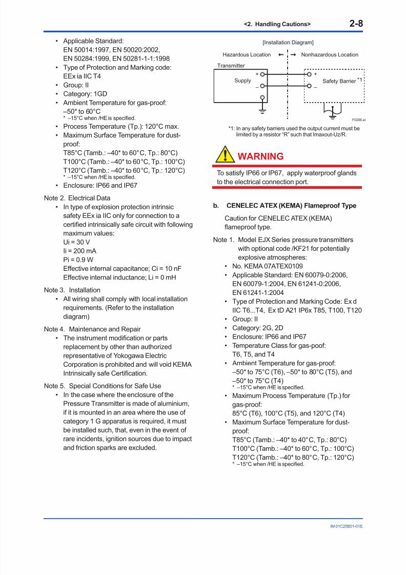
2.9.3 CENELEC ATEX (KEMA)Certication
(1) Technical Data
a. CENELEC ATEX (KEMA) Intrinsically Safe
Type
Caution for CENELEC ATEX (KEMA)Intrinsically safe type.
Note 1. Model EJX Series pressure transmitterswith optional code /KS2 for potentiallyexplosive atmospheres:
• No. KEMA 03ATEX1544 X
8/9/2019 YOKOGAWA TRANSMITTERS9(EJX110A, EJX120A, EJX130A, EJX310A, EJX430A, and EJX440A)
http://slidepdf.com/reader/full/yokogawa-transmitters9ejx110a-ejx120a-ejx130a-ejx310a-ejx430a-and-ejx440a 16/78
<2. Handling Cautions> 2-8
IM 01C25B01-01E
• Applicable Standard:EN 50014:1997, EN 50020:2002,EN 50284:1999, EN 50281-1-1:1998
• Type of Protection and Marking code:EEx ia IIC T4
• Group: II• Category: 1GD
• Ambient Temperature for gas-proof: –50* to 60°C* –15°C when /HE is specied.
• Process Temperature (Tp.): 120°C max.• Maximum Surface Temperature for dust-
proof:T85°C (Tamb.: –40* to 60°C, Tp.: 80°C)T100°C (Tamb.: –40* to 60°C, Tp.: 100°C)T120°C (Tamb.: –40* to 60°C, Tp.: 120°C)* –15°C when /HE is specied.
• Enclosure: IP66 and IP67
Note 2. Electrical Data• In type of explosion protection intrinsicsafety EEx ia IIC only for connection to acertied intrinsically safe circuit with followingmaximum values:
Ui = 30 V Ii = 200 mA Pi = 0.9 W Effective internal capacitance; Ci = 10 nF Effective internal inductance; Li = 0 mH
Note 3. Installation
• All wiring shall comply with local installationrequirements. (Refer to the installationdiagram)
Note 4. Maintenance and Repair • The instrument modication or parts
replacement by other than authorizedrepresentative of Yokogawa ElectricCorporation is prohibited and will void KEMAIntrinsically safe Certication.
Note 5. Special Conditions for Safe Use• In the case where the enclosure of the
Pressure Transmitter is made of aluminium,if it is mounted in an area where the use ofcategory 1 G apparatus is required, it mustbe installed such, that, even in the event ofrare incidents, ignition sources due to impactand friction sparks are excluded.
Transmitter
Supply Safety Barrier *1
Nonhazardous Location
[Installation Diagram]
Hazardous Location
+
–
+
–
F0206.ai
*1: In any safety barriers used the output current must belimited by a resistor “R” such that Imaxout-Uz/R.
WARNING
To satisfy IP66 or IP67, apply waterproof glandsto the electrical connection port.
b. CENELEC ATEX (KEMA) Flameproof Type
Caution for CENELEC ATEX (KEMA)ameproof type.
Note 1. Model EJX Series pressure transmitterswith optional code /KF21 for potentiallyexplosive atmospheres:
• No. KEMA 07ATEX0109• Applicable Standard: EN 60079-0:2006,
EN 60079-1:2004, EN 61241-0:2006,EN 61241-1:2004
• Type of Protection and Marking Code: Ex dIIC T6...T4, Ex tD A21 IP6x T85, T100, T120
• Group: II• Category: 2G, 2D• Enclosure: IP66 and IP67• Temperature Class for gas-poof:
T6, T5, and T4• Ambient Temperature for gas-proof:
–50* to 75°C (T6), –50* to 80°C (T5), and –50* to 75°C (T4)* –15°C when /HE is specied.
• Maximum Process Temperature (Tp.) for
gas-proof: 85°C (T6), 100°C (T5), and 120°C (T4)• Maximum Surface Temperature for dust-
proof:T85°C (Tamb.: –40* to 40°C, Tp.: 80°C)T100°C (Tamb.: –40* to 60°C, Tp.: 100°C)T120°C (Tamb.: –40* to 80°C, Tp.: 120°C)* –15°C when /HE is specied.

8/9/2019 YOKOGAWA TRANSMITTERS9(EJX110A, EJX120A, EJX130A, EJX310A, EJX430A, and EJX440A)
http://slidepdf.com/reader/full/yokogawa-transmitters9ejx110a-ejx120a-ejx130a-ejx310a-ejx430a-and-ejx440a 17/78
<2. Handling Cautions> 2-9
IM 01C25B01-01E
Note 2. Electrical Data• Supply voltage: 42 V dc max.• Output signal: 4 to 20 mA
Note 3. Installation• All wiring shall comply with local installation
requirement.
• The cable entry devices shall be of a certiedameproof type, suitable for the conditions ofuse.
Note 4. Operation• Keep the “WARNING” label attached to the
transmitter. WARNING: AFTER DE-ENERGIZING,
DELAY 5 MINUTES BEFORE OPENING.WHEN THE AMBIENT TEMP.≥65°C, USEHEAT-RESISTING CABLES≥90°C.
• Take care not to generate mechanical
sparking when accessing to the instrumentand peripheral devices in a hazardouslocation.
Note 5. Maintenance and Repair • The instrument modication or part
replacement by other than an authorizedrepresentative of Yokogawa ElectricCorporation is prohibited and will void KEMAFlameproof Certication.
WARNING
To satisfy IP66 or IP67, apply waterproof glandsto the electrical connection port.
c. CENELEC ATEX (KEMA) Intrinsically Safe
Type/CENELEC ATEX (KEMA) Flameproof
Type/CENELEC ATEX Type n
Model EJX Series pressure transmitters withoptional code /KU21 or /V1U can be selectedthe type of protection CENELEC ATEX (KEMA)Intrinsically Safe, Flameproof or CENELEC ATEX Type n for use in hazardous locations.
Note 1. For the installation of this transmitter,once a particular type of protection isselected, any other type of protectioncannot be used. The installation must be inaccordance with the description about thetype of protection in this user’s manual.
Note 2. In order to avoid confusion, unnecessarymarking is crossed out on the label otherthan the selected type of protection whenthe transmitter is installed.
CENELEC ATEX Type of Protection “n”
• Applicable Standard: EN 60079-15
• Referential Standards: IEC60079-0,IEC 60079-11
• Type of Protection and Marking Code:Ex nL IIC T4
• Temperature Class: T4• Enclosure: IP66 and IP67• Process Temperature: 120°C max.• Ambient Temperature: –50* to 60°C
* –15°C when /HE is specied.
Note 1. Electrical Data Ui = 30 V
Effective internal capacitance; Ci = 10 nF Effective internal inductance; Li = 0 mH
Note 2. Installation• All wiring shall comply with local installation
requirements. (refer to the installationdiagram)
Note 3. Maintenance and Repair • The instrument modication or parts
replacement by other than authorizedrepresentative of Yokogawa ElectricCorporation is prohibited and will void Type
of Protection “n”.
[Ex nL]
Power Supply
(Zone 2 only)
Transmitter
Supply
Nonhazardous Location
[Installation Diagram]
Hazardous Location
+
–
+
–
F0207.ai
Ratings of the Power Supply as follows;
Maximum Voltage: 30 V

8/9/2019 YOKOGAWA TRANSMITTERS9(EJX110A, EJX120A, EJX130A, EJX310A, EJX430A, and EJX440A)
http://slidepdf.com/reader/full/yokogawa-transmitters9ejx110a-ejx120a-ejx130a-ejx310a-ejx430a-and-ejx440a 18/78
<2. Handling Cautions> 2-10
IM 01C25B01-01E
(2) Electrical Connection
A mark indicating the electrical connection typeis stamped near the electrical connection port.These marks are as followed.
F0208.ai
Location of the mark
Screw Size Marking
ISO M20 × 1.5 female
ANSI 1/2 NPT female
M
A or W
(3) Installation
WARNING
• All wiring shall comply with local installationrequirements and the local electrical code.
• There is no need for conduit seal in Division1 and Division 2 hazardous locationsbecause this product is sealed at the factory.
(4) Operation
WARNING
• OPEN CIRCUIT BEFORE REMOVINGCOVER. INSTALL IN ACCORDANCE WITHTHIS USER’S MANUAL
• Take care not to generate mechanicalsparking when access to the instrument andperipheral devices in a hazardous location.
(5) Maintenance and Repair
WARNING
The instrument modication or parts replacementby other than an authorized Representative ofYokogawa Electric Corporation is prohibited andwill void the certication.
(6) Name Plate
Name plate
Tag plate for flameproof type
Tag plate for intrinsically safe type
Tag plate for type n protection
F0209.ai
D
D
AFTER DE-ENERGIZING, DELAY 5 MINUTESBEFORE OPENING.WHEN THE AMBIENT TEMP. ≥ 65°C,USE THE HEAT-RESISTING CABLES ≥ 90°C
No. KEMA 07ATEX0109Ex d IIC T6...T4, Ex tD A21, IP6XEnlcosure : IP66, IP67TEMP. CLASS T6 T5 T4MAX PROCESS TEMP.(Tp.) 85 100 120 °CTamb. -50(-15) to 75 80 75 °CT85°C(Tamb.:40°C, Tp.:80°C),T100°C(Tamb.:60°C, Tp.:100°C),T120°C(Tamb.:80°C, Tp.:120°C) Min.Tamb.:-40(-15)°C(for Dust)
No. KEMA 03ATEX1544 XEEx ia IIC T4IP66 and IP67Tamb. -50(-15) to 60°C MIN. Tamb.:-40(-15)°C(for DUST)MAX. PROCESS TEMP.(Tp.) 120°CT85°C(Tp.:80°C), T100°C(Tp.:100°C), T120°C(Tp.:120°C)Ui=30V, Ii=200mA , Pi=0.9W, Ci =10nF, Li= 0
WARNING
EEx nLIIC T4IP66 and IP67Tamb. -50(-15) to 60°CMAX. PROCESS TEMP.(Tp.) 120°CUi=30V, Ci=10nF, Li=0
MODEL: Specied model code.STYLE: Style code.SUFFIX: Specied sufx code.
SUPPLY: Supply voltage.OUTPUT: Output signal.MWP: Maximum working pressure.CAL RNG: Specied calibration range.NO.: Serial number and year of production*1.TOKYO 180-8750 JAPAN:The manufacturer name and the address*2.
*1: The rst digit in the nal three numbers of the serialnumber appearing after “NO.” on the nameplateindicates the year of production. The following is anexample of a serial number for a product that wasproduced in 2010:
The year 2010
91K819857 032
*2: “180-8750” is a zip code which represents thefollowing address.
2-9-32 Nakacho, Musashino-shi, Tokyo Japan

8/9/2019 YOKOGAWA TRANSMITTERS9(EJX110A, EJX120A, EJX130A, EJX310A, EJX430A, and EJX440A)
http://slidepdf.com/reader/full/yokogawa-transmitters9ejx110a-ejx120a-ejx130a-ejx310a-ejx430a-and-ejx440a 19/78
<2. Handling Cautions> 2-11
IM 01C25B01-01E
2.9.4 IECEx Certication
Model EJX Series pressure transmitters withoptional code /SU2 can be selected the type ofprotection (IECEx Intrinsically Safe/type n orameproof) for use in hazardous locations.
Note 1. For the installation of this transmitter,
once a particular type of protection isselected, any other type of protectioncannot be used. The installation must be inaccordance with the description about thetype of protection in this instruction manual.
Note 2. In order to avoid confusion, unnecessarymarking is crossed out on the label otherthan the selected type of protection whenthe transmitter is installed.
a. IECEx Intrinsically Safe Type / type n
Caution for IECEx Intrinsically safe and type n.Note 1. Model EJX Series differential, gauge,
and absolute pressure transmitters withoptional code /SU2 are applicable for usein hazardous locations
• No. IECEx CSA 05.0005• Applicable Standard: IEC 60079-0:2000,
IEC 60079-11:1999, IEC 60079-15:2001• Ex ia IIC T4, Ex nL IIC T4• Ambient Temperature: –50* to 60°C
* –15°C when /HE is specied.
• Max. Process Temp.: 120°C• Enclosure: IP66 and IP67
Note 2. Entity Parameters• Intrinsically safe ratings are as follows:
Maximum Input Voltage (Vmax/Ui) = 30 VMaximum Input Current (Imax/Ii) = 200 mAMaximum Input Power (Pmax/Pi) = 0.9 WMaximum Internal Capacitance (Ci) = 10 nFMaximum Internal Inductance (Li) = 0 µH
• Type "n" ratings are as follows:Maximum Input Voltage (Vmax/Ui) = 30 V
Maximum Internal Capacitance (Ci) = 10 nFMaximum Internal Inductance (Li) = 0 µH• Installation Requirements
Uo ≤ Ui, Io ≤ Ii, Po ≤ Pi,Co ≥ Ci + Ccable, Lo ≥ Li + LcableVoc ≤ Vmax, Isc ≤ Imax,Ca ≥ Ci + Ccable, La ≥ Li + LcableUo, Io, Po, Co, Lo, Voc, Isc, Ca and La areparameters of barrier.
Note 3. Installation• In any safety barrier used output current
must be limited by a resistor 'R' such thatIo=Uo/R.
• The safety barrier must be IECEx certied.• Input voltage of the safety barrier must be
less than 250 Vrms/Vdc.
• The instrument modication or partsreplacement by other than authorizedrepresentative of Yokogawa ElectricCorporation and will void IECEx Intrinsicallysafe and type n certication.
F0210-1.ai
EJX Series Pressure
Transmitters
IECEx certifiedSafety Barrier
Supply
Hazardous Location Nonhazardous Location
General
PurposeEquipment
+
–
+
–
+
–
+
–
[Intrinsically Safe]
Group IIC, Zone 0
F0210-2.ai
EJX Series Pressure
Transmitters
Supply
Hazardous Location Nonhazardous Location
+
–
+
–
Not Use
Safety Barrier
[type n]
IECEx Certified
Equipment [nL]EJX Series Pressure
Transmitters
Group IIC, Zone 2
b. IECEx Flameproof Type
Caution for IECEx ameproof type.
Note 1. Model EJX Series pressure transmitterswith optional code /SF2 or /SU2 areapplicable for use in hazardous locations:
• No. IECEx CSA 07.0008• Applicable Standard: IEC60079-0:2004,
IEC60079-1:2003
• Flameproof for Zone 1, Ex d IIC T6...T4• Enclosure: IP66 and IP67• Maximum Process Temperature: 120°C (T4),
100°C (T5), 85°C (T6)• Ambient Temperature: –50* to 75°C (T4),
–50* to 80°C (T5), –50* to 75°C (T6)* –15°C when /HE is specied.
• Supply Voltage: 42 V dc max.• Output Signal: 4 to 20 mA dc

8/9/2019 YOKOGAWA TRANSMITTERS9(EJX110A, EJX120A, EJX130A, EJX310A, EJX430A, and EJX440A)
http://slidepdf.com/reader/full/yokogawa-transmitters9ejx110a-ejx120a-ejx130a-ejx310a-ejx430a-and-ejx440a 20/78
<2. Handling Cautions> 2-12
IM 01C25B01-01E
Note 2. Wiring• In hazardous locations, the cable entry
devices shall be of a certied ameprooftype, suitable for the conditions of use andcorrectly installed.
• Unused apertures shall be closed withsuitable ameproof certied blanking
elements.
Note 3. Operation• WARNING:
AFTER DE-ENERGIZING, DELAY 5MINUTES BEFORE OPENING.
• WARNING:WHEN AMBIENT TEMPERATURE ≥ 65°C,USE THE HEAT-RESISTING CABLES ≥90°C.
• Take care not to generate mechanicalsparking when accessing to the instrument
and peripheral devices in a hazardouslocation.
Note 4. Maintenance and Repair • The instrument modication or parts
replacement by other than authorizedrepresentative of Yokogawa ElectricCorporation is prohibited and will void IECExCertication.
2.10 EMC Conformity Standards
EN61326-1 Class A, Table2 (For use in industriallocations)EN61326-2-3
CAUTION
To meet EMC regulations, Yokogawarecommends that customers run signalwiring through metal conduits or use shieldedtwisted-pair cabling when installing EJX seriestransmitters in a plant.
2.11 Pressure Equipment
Directive (PED)
(1) General
• EJX Series pressure transmitters arecategorized as piping under the pressureaccessories section of directive 97/23/EC,which corresponds to Article 3, Paragraph 3 ofPED, denoted as Sound Engineering Practice
(SEP).
• EJX110A-MS, EJX110A-HS,EJX110A-VS, EJX130A, EJX440A,EJX510A-D, and EJX530A-D can be usedabove 200 bar and therefore considered asa part of a pressure retaining vessel wherecategory III, Module H applies. These modelswith option code /PE3 conform to that category.
(2) Technical Data
• Models without /PE3 Article 3, Paragraph 3 of PED, denoted asSound Engineering Practice (SEP).
• Models with /PE3 Module: H Type of Equipment: Pressure Accessory-Vessel Type of uid: Liquid and Gas Group of uid: 1 and 2
ModelCapsule
code
PS*1
(bar)V(L)
PS.V
(bar.L)Category*2
EJX110AL 160 0.01 1.6 Article 3,
Paragraph 3(SEP)M, H, V 250 0.01 2.5
EJX110Awith code
/PE3M, H, V 250 0.01 2.5 III
EJX130A M, H 500 0.01 5.0 Article 3,
Paragraph 3(SEP)
EJX130Awith code
/PE3M, H 500 0.01 5.0 III
EJX310A L, M, A, B 160 0.01 1.6
Article 3,
Paragraph 3(SEP)
EJX430A H, A, B 160 0.01 1.6 Article 3,
Paragraph 3(SEP)
EJX440A C, D 500 0.1 5.0 Article 3,
Paragraph 3(SEP)
EJX440Awith code
/PE3C, D 500 0.1 5.0 III
EJX510A A, B, C 100 0.1 10 Article 3,
Paragraph 3(SEP)D 700 0.1 70
EJX510Awith code/PE3
D 700 0.1 70 III
EJX530A A, B, C 100 0.1 10 Article 3,
Paragraph 3(SEP)D 700 0.1 70
EJX530Awith code
/PE3D 700 0.1 70 III
*1: PS is maximum pressure for vessel itself based onPressure Equipment Directive 97/23/EC. Refer toGeneral Specication for maximum working pressure of atransmitter.
*2: Referred to Table 1 covered by ANNEX II of EC Directiveon Pressure Equipment Directive 97/23/EC

8/9/2019 YOKOGAWA TRANSMITTERS9(EJX110A, EJX120A, EJX130A, EJX310A, EJX430A, and EJX440A)
http://slidepdf.com/reader/full/yokogawa-transmitters9ejx110a-ejx120a-ejx130a-ejx310a-ejx430a-and-ejx440a 21/78
<2. Handling Cautions> 2-13
IM 01C25B01-01E
(3) Operation
CAUTION
• The temperature and pressure of uid shouldbe maintained at levels that are consistentwith normal operating conditions.
• The ambient temperature should bemaintained at a level that is consistent withnormal operating conditions.
• Please take care to prevent water hammerand the like from inducing excessivepressures in pipes and valves. If phenomenaare likely, install a safety valve or takesome other appropriate measure to preventpressure from exceeding PS.
• Take appropriate measures at the device orsystem level to protect transmitters if they
are to be operated near an external heatsource.
2.12 Low Voltage Directive
Applicable standard: EN61010-1
(1) Pollution Degree 2
"Pollution degree" describes the degree towhich a solid, liquid, or gas which deterioratesdielectric strength or surface resistivity is
adhering. " 2 " applies to normal indooratmosphere. Normally, only non-conductivepollution occurs. Occasionally, however,temporary conductivity caused by condensationmust be expected.
(2) Installation Category I
"Overvoltage category (Installation category)"describes a number which denes a transientovervoltage condition. It implies the regulationfor impulse withstand voltage. " I " applies toelectrical equipment which is supplied from thecircuit when appropriate transient overvoltagecontrol means (interfaces) are provided.

8/9/2019 YOKOGAWA TRANSMITTERS9(EJX110A, EJX120A, EJX130A, EJX310A, EJX430A, and EJX440A)
http://slidepdf.com/reader/full/yokogawa-transmitters9ejx110a-ejx120a-ejx130a-ejx310a-ejx430a-and-ejx440a 22/78
<3. Component Names> 3-1
IM 01C25B01-01E
3. Component Names
HIGH LOW
Slide switch
Burnout direction switch
Write protection switch
Burnout DirectionSwitch Position
BO H L
WR E D
H L H L
Burnout direction switch (BO)
Burnout Direction
F0301.ai
Write ProtectionSwitch Position
H L
E D
H L
E D
Write Protection
Hardware write protection switch (WR)
YES(Write disabled)
NO(Write enabled)
Vertical impulse piping type
Pressure-detector section
Cover flange
Terminal box cover
Horizontal impulse piping type
External indicator conduit connection (Note 1)
Vent plug
Drain plug
Transmitter section
Integralindicator (Note 1)
Mounting screw
Range-settingswitch (Note 1)
(See section 7.6)
Amplifier Cover
CPU assembly
Zero-adjustmentscrew
Conduitconnection
Processconnector (Note 1)
Processconnection
(Note 2)
Note 1: See subsection 9.2, “Model and Sufx Codes,” for details. A process connector will not be applied for lower side of EJX310A,
EJX430A, and EJX440A.Note 2: Applicable for BRAIN/HART communication type. Set the switches as shown in the gure above to set the burn-out directionand write protection. The Burnout switch is set to the H side for delivery (unless option code /C1 or /C2 is specied in the order),and the hardware write protection switch is set to E side. The setting of the switches can be conrmed via communication. Anexternal zero adjustment screw can only be disabled by communication. To disable the screw, set a parameter before activatingthe hardware write protect function. See each communication manual.
Figure 3.1 Component Names
Table 3.1 Display Symbol
Display Symbol Meaning of Display Symbol
Display mode is ‘square root’. (Display is not lit when ‘linear’ mode.)
The output signal being zero-adjusted is increasing.
The output signal being zero-adjusted is decreasing.
F0302.ai
Write protect function is enabled.

8/9/2019 YOKOGAWA TRANSMITTERS9(EJX110A, EJX120A, EJX130A, EJX310A, EJX430A, and EJX440A)
http://slidepdf.com/reader/full/yokogawa-transmitters9ejx110a-ejx120a-ejx130a-ejx310a-ejx430a-and-ejx440a 23/78
<4. Installation> 4-1
IM 01C25B01-01E
4. Installation
4.1 Precautions
Before installing the transmitter, read the cautionarynotes in section 2.4, “Selecting the Installation
Location.” For additional information on theambient conditions allowed at the installationlocation, refer to subsection 9.1 “StandardSpecications.”
IMPORTANT
• When welding piping during construction,take care not to allow welding currents toow through the transmitter.
• Do not step on this instrument afterinstallation.
• For the EJX430A and EJX440A, theatmospheric opening is located on the lowpressure side cover ange. The openingmust not face upward. See section 9.4,“Dimensions,” for the location of the opening.
4.2 Mounting
The transmitter is shipped with the processconnection, according to the ordering
specications. To change the orientation of theprocess connections, refer to section 4.3. With differential pressure transmitters,
the distance between the impulse pipingconnection ports is usually 54 mm (gure 4.1).By changing the orientation of the processconnector, the dimension can be changed to 51mm or 57 mm.
The transmitter can be mounted on a nominal50 mm (2-inch) pipe using the mountingbracket supplied, as shown in gure 4.2 and4.3 The transmitter can be mounted on either a
horizontal or a vertical pipe. When mounting the bracket on the transmitter,
tighten the (four) bolts that hold the transmitterwith a torque of approximately 39 N·m 4kgf·m.
57 mm 54 mm 51 mm
F0401.ai
Figure 4.1 Process Connector Impulse PipingConnection Distances for DifferentialPressure Transmitters
Figure 4.1 and 4.2 shows the mounting of thetransmitter for horizontal piping and vertical pipingwith using the mounting bracket. The transmitterswith the installation code -U (Universal ange) canbe used for either type of mounting.
Horizontal pipe mounting
Vertical pipe mounting
Transmitter mounting bolt
U-bolt nut
Mounting bracket
U-bolt nut
Mounting bracket
50 mm(2-inch) pipe
50 mm(2-inch) pipe
U-bolt
U-bolt
F0402.ai
Transmitter mounting bolt
Figure 4.2 Transmitter Mounting (HorizontalImpulse Piping Type)

8/9/2019 YOKOGAWA TRANSMITTERS9(EJX110A, EJX120A, EJX130A, EJX310A, EJX430A, and EJX440A)
http://slidepdf.com/reader/full/yokogawa-transmitters9ejx110a-ejx120a-ejx130a-ejx310a-ejx430a-and-ejx440a 24/78
<4. Installation> 4-2
IM 01C25B01-01E
F0403.ai
Vertical pipe mounting(Process connector upside)
Vertical pipe mounting(Process connector downside)
Transmitter mounting bolt
Transmitter mounting bolt
Mounting bracket
Mounting bracket
U-bolt nut
U-bolt nut
U-bolt
U-bolt
50 mm(2-inch) pipe
50 mm(2-inch) pipe
Figure 4.3 Transmitter Mounting (Vertical ImpulsePiping Type)
4.3 Changing the Process
Connection
The transmitter is shipped with the processconnection specied at the time of ordering. Tochange the process connection, the drain (vent)plug must be repositioned.
To reposition a drain (vent) plug, use a wrench toslowly and gently unscrew it. Then, remove andremount it on the opposite side. Wrap sealing tapearound the drain (vent) plug threads (*1 in the gurebelow), and apply a lubricant to the threads of thedrain (vent) screw(s) (*2 below). To tighten the drain(vent) plugs, apply a torque of 34 to 39 N·m (3.5 to 4kgf·m). Process connector bolts are to be tighteneduniformly to a torque shown in table 4.1.
Table 4.1 Torque
Model
EJX110AEJX120AEJX130AEJX310AEJX430A
EJX440A
C capsule D capsule
Torque(N·m)kgf·m
39 to 49 4 to 549 to 595 to 6
F0404.ai
*1
*2Drain/vent plug Note: For a horizontal impulsepiping type, moving theprocess connectors fromthe front side to theback cannot be made.
Vertical impulse piping type Horizontal impulse piping type
Bolt
Processconnector
gasket
Figure 4.4 Changing Process Connection

8/9/2019 YOKOGAWA TRANSMITTERS9(EJX110A, EJX120A, EJX130A, EJX310A, EJX430A, and EJX440A)
http://slidepdf.com/reader/full/yokogawa-transmitters9ejx110a-ejx120a-ejx130a-ejx310a-ejx430a-and-ejx440a 25/78
<4. Installation> 4-3
IM 01C25B01-01E
4.4 Swapping the High/Low-
pressure Side Connection
IMPORTANT
This section is applicable only for EJX110A,EJX120A, and EJX130A differential transmitters,and not applicable for gauge or absolutepressure transmitters.
4.4.1 Rotating Pressure-detector Section
180°
This procedure can be applied only to a transmitterwith a vertical impulse piping type.
The procedure below can be used to turn thepressure detector assembly 180°. Performthis operation in a maintenance shop with thenecessary tools laid out and ready for use, and theninstall the transmitter in the eld after making thechange.
1) Use an Allen wrench (JIS B4648, nominal 2.5mm) to remove the two setscrews at the jointbetween the pressure-detector section andtransmitter section.
2) Leaving the transmitter section in position,rotate the pressure-detector section 180°.
3) Tighten the two setscrews to x the pressure-detector section and transmitter sectiontogether (at a torque of 1.5 N·m).
Reposition the process connector and drain(vent) plugs to the opposite side as described insubsection 4.3.
F0405.ai
Process connector
Setscrew
Before After rotating 180°
Figure 4.5 Before and After Modication
4.4.2 Using the Communicator
This method is applicable only to the ModelEJX110A, EJX120A, and EJX130A.
With a communicator, you can change whichprocess connection is used as the high-pressureside without mechanically rotating the pressure-
detector section 180 as described in subsection4.4.1. To change, call parameter ‘D15: H/L SWAP’for BRAIN Communication or ‘H/L swap’ for HARTCommunication and select REVERSE (right side:low pressure; left side: high pressure) or selectNORMAL to change back to normal (right side: highpressure; left side: low pressure).
Output
Input
NORMAL
REVERSEF0406.ai
Figure 4.6 Input/Output Relationship
IMPORTANT
Since the H/L label plate on the capsuleassembly will remain unchanged, use thisfunction only when you cannot switch theimpulse piping. If the ‘H/L SWAP’ parametersetting is changed, the input/output relationshipis reversed as shown in gure 4.6; be sure this isunderstood by all.

8/9/2019 YOKOGAWA TRANSMITTERS9(EJX110A, EJX120A, EJX130A, EJX310A, EJX430A, and EJX440A)
http://slidepdf.com/reader/full/yokogawa-transmitters9ejx110a-ejx120a-ejx130a-ejx310a-ejx430a-and-ejx440a 26/78
<4. Installation> 4-4
IM 01C25B01-01E
4.5 Rotating Transmitter Section
The transmitter section can be rotatedapproximately 360° (180° to either direction or360° to one direction from the original position atshipment, depending on the conguration of theinstrument.) It can be xed at any angle within
above range.1) Remove the two setscrews that fasten the
transmitter section and capsule assembly,using the Allen wrench.
2) Rotate the transmitter section slowly and stop itat designated position.
3) Tighten the two setscrews to a torque of 1.5N·m.
IMPORTANT
Do not rotate the transmitter section more than
the above limit.
F0407.ai
Vertical impulse piping type
Horizontal impulse piping type
Pressure-detector section
Transmitter section
Rotate 0 to ±180° segments
Rotate 0 to ±180° segments
Transmitter section
Pressure-detector section
Conduit connection
Conduit connection
Zero-adjustment screw
Stopper
Figure 4.7 Rotating Transmitter Section (Left SideHigh Pressure Type)
4.6 Changing the Direction of
Integral Indicator
IMPORTANT
Always turn OFF power, release pressure andremove a transmitter to non-hazardous areabefore disassembling and reassmbling anindicator.
An integral indicator can be installed in thefollowing three directions. Follow the instructions insection 8.4 for removing and attaching the integralindicator.
F0408.ai
Figure 4.8 Integral Indicator Direction

8/9/2019 YOKOGAWA TRANSMITTERS9(EJX110A, EJX120A, EJX130A, EJX310A, EJX430A, and EJX440A)
http://slidepdf.com/reader/full/yokogawa-transmitters9ejx110a-ejx120a-ejx130a-ejx310a-ejx430a-and-ejx440a 27/78
<5. Installing Impulse Piping> 5-1
IM 01C25B01-01E
5. Installing Impulse Piping
5.1 Impulse Piping Installation
Precautions
The impulse piping that connects the processoutputs to the transmitter must convey the processpressure accurately. If, for example, gas collectsin a liquid-lled impulse line, or the drain for agas-lled impulse line becomes plugged, it willnot convey the pressure accurately. Since this willcause errors in the measurement output, selectthe proper piping method for the process uid(gas, liquid, or steam). Pay careful attention to thefollowing points when routing the impulse pipingand connecting the impulse piping to a transmitter.
5.1.1 Connecting Impulse Piping to aTransmitter
(1) Check the High and Low Pressure
Connections on the Transmitter (Figure 5.1)
Symbols “H” and “L” have been placed on thecapsule assembly to indicate high and low pressureside. With differential pressure transmitters, connectthe high pressure side impulse line to the “H” side,and the low pressure side impulse line to the “L”side.
With gauge/absolute pressure transmitters, connectthe impulse line to the ‘H’ side.
F0501.ai
Pressureconnection
“H” and “L” are shown
Process connection
Process connector
Bolt
Differential Pressure Transmitter
“H” and “L” are shown
Process connection
Process connector
Bolt
Gauge/Absolute Pressure Transmitters
Figure 5.1 “H” and “L” Symbols on a CapsuleAssembly
(2) Changing the Process Connector Piping
Connections (Figure 4.1) (for differential
pressure transmitters)
The impulse piping connection distances can bechanged between 51 mm, 54 mm and 57 mm bychanging the orientation of the process connectors.This is convenient for aligning an impulse line with aprocess connectors.
(3) Tightening the Process Connector Mounting
Bolts
After connecting an impulse line, tighten theprocess connector mounting bolts uniformly.
(4) Removing the Impulse Piping ConnectingPort Dustproof Cap
The impulse piping connecting port on thetransmitter is covered with a plastic cap to keep outdust. This cap must be removed before connectingthe line. (Be careful not to damage the threadswhen removing this cap. Never insert a screwdriveror other tool between the cap and port threads toremove the cap.)
(5) Connecting the Transmitter and 3-
Valve Manifold (for differential pressure
transmitters)
A 3-valve manifold consists of two stop valves toblock process pressure and an equalizing valveto equalize the pressures on the high and lowpressure sides of the transmitter. Such a manifoldmakes it easier to disconnect the transmitterfrom the impulse piping, and is convenient whenadjusting the transmitter zero point.
There are two 3-valve manifold types: the pipe-mounting type and the direct-mounting type; care
should be taken with respect to the following pointswhen connecting the manifold to the transmitter.

8/9/2019 YOKOGAWA TRANSMITTERS9(EJX110A, EJX120A, EJX130A, EJX310A, EJX430A, and EJX440A)
http://slidepdf.com/reader/full/yokogawa-transmitters9ejx110a-ejx120a-ejx130a-ejx310a-ejx430a-and-ejx440a 28/78
<5. Installing Impulse Piping> 5-2
IM 01C25B01-01E
Pipe-Mounting Type 3-Valve Manifold(Figure 5.2)
1) Screw nipples into the connection ports on thetransmitter side of the 3-valve manifold, andinto the impulse piping connecting ports onthe process connectors. (To maintain proper
sealing, wind sealing tape around the nipplethreads.)2) Mount the 3-valve manifold on the 50 mm (2-
inch) pipe by fastening a U-bolt to its mountingbracket. Tighten the U-bolt nuts only lightly atthis time.
3) Install the pipe assemblies between the 3-valvemanifold and the process connectors and lightlytighten the ball head lock nuts. (The ball-shapedends of the pipes must be handled carefully,since they will not seal properly if the ballsurface is scratched or otherwise damaged.)
4) Now tighten the nuts and bolts securely in thefollowing sequence:
Process connector bolts → transmitter-end ballhead lock nuts → 3-valve manifold ball headlock nuts → 3-valve manifold mounting bracketU-bolt nuts
F0502.ai
Nipple
Nipple
Processconnector
Ball headlock nut
Pipe
Ball headlock nut
Processconnector bolts
50 mm(2-inch) pipe
Pipes
3-valvemanifold
Impulse piping
Vent plug(optional)
Stop valve(low pressure side)
Equalizing valve(balancing)
Stop valve(high pressure side)
Figure 5.2 3-Valve Manifold (Pipe-Mounting Type)
Direct-Mounting Type 3-Valve Manifold(Figure 5.3)
1) Mount the 3-valve manifold on the transmitter. (When mounting, use the two gaskets and the
four bolts provided with the 3-valve manifold.Tighten the bolts evenly.)
2) Mount the process connectors and gasketson the top of the 3-valve manifold (the side onwhich the impulse piping will be connected).
Bolts
Processconnector
Gasket
Gasket
Processconnector
Bolts
Stop valve
Stop valve
3-valvemanifold
3-valvemanifold
Equalizing valve
Equalizingvalve
Stop valve
Impulsepiping
Impulsepiping
Stop valve
F0503.ai
Figure 5.3 3-Valve Manifold (Direct-MountingType)
NOTE
After completing the connection of the transmitterand 3-valve manifold, be sure to CLOSE the lowpressure and high pressure stop valves, OPENthe equalizing valve, and leave the manifold withthe equalizing valve OPEN.You must do this in order to avoid overloadingthe transmitter from either the high or the lowpressure side when beginning operation.This instruction must also be followed as part ofthe startup procedure (chapter 7.)

8/9/2019 YOKOGAWA TRANSMITTERS9(EJX110A, EJX120A, EJX130A, EJX310A, EJX430A, and EJX440A)
http://slidepdf.com/reader/full/yokogawa-transmitters9ejx110a-ejx120a-ejx130a-ejx310a-ejx430a-and-ejx440a 29/78
<5. Installing Impulse Piping> 5-3
IM 01C25B01-01E
5.1.2 Routing the Impulse Piping
(1) Process Pressure Tap Angles
If condensate, gas, sediment or other extraneousmaterial in the process piping gets into the impulsepiping, pressure measurement errors may result. Toprevent such problems, the process pressure tapsmust be angled as shown in gure 5.4 according tothe kind of uid being measured.
NOTE
• If the process uid is a gas, the taps must bevertical or within 45° either side of vertical.
• If the process uid is a liquid, the taps mustbe horizontal or below horizontal, but notmore than 45° below horizontal.
• If the process uid is steam or other
condensing vapor, the taps must behorizontal or above horizontal, but not morethan 45° above horizontal.
[Gas]
Pressuretaps
Processpiping
[Steam][Liquid]
45°
45°
45° 45°
45°
45°
F0504.ai
Figure 5.4 Process Pressure Tap Angle(For Horizontal Piping)
(2) Position of Process Pressure Taps and
Transmitter
If condensate (or gas) accumulates in the impulsepiping, it should be removed periodically byopening the drain (or vent) plugs. However, this willgenerate a transient disturbance in the pressuremeasurement, and therefore it is necessary toposition the taps and route the impulse piping sothat any extraneous liquid or gas generated in theleadlines returns naturally to the process piping.
• If the process uid is a gas, then as a rule thetransmitter must be located higher than theprocess pressure taps.
• If the process uid is a liquid or steam, then as arule the transmitter must be located lower thanthe process pressure taps.
(3) Impulse Piping Slope
The impulse piping must be routed with only anupward or downward slope. Even for horizontalrouting, the impulse piping should have a slope ofat least 1/10 to prevent condensate (or gases) fromaccumulating in the pipes.
(4) Temperature Difference Between Impulse
Lines (for differential pressure transmitters)
If there is a temperature difference between thehigh and low impulse lines, the density differenceof the uids in the two lines will cause an error inthe measurement pressure. When measuring ow,impulse lines must be routed together so that thereis no temperature difference between them.
(5) Condensate Pots for Steam Flow
Measurement (for differential pressure
transmitters)
If the liquid in the impulse piping repeatedlycondenses or vaporizes as a result of changesin the ambient or process temperature, this willcause a difference in the uid head between thehigh pressure and low pressure sides. To preventmeasurement errors due to these head differences,condensate pots are used when measuring steamow.
(6) Preventing Wind Speed Effects in Very Low
Differential Pressure Measurement
(for differential pressure transmitters)
IMPORTANT
When using a differential pressure transmitterto measure very low pressures (draft pressure),the low pressure connection port is left opento atmospheric pressure (the referencepressure). Any wind around the differentialpressure transmitter will therefore cause errorsin the measurement. To prevent this, it will benecessary either to enclose the transmitter ina box, or to connect an impulse line to the lowpressure side and insert its end into a wind-excluding pot (cylindrical with a base plate).

8/9/2019 YOKOGAWA TRANSMITTERS9(EJX110A, EJX120A, EJX130A, EJX310A, EJX430A, and EJX440A)
http://slidepdf.com/reader/full/yokogawa-transmitters9ejx110a-ejx120a-ejx130a-ejx310a-ejx430a-and-ejx440a 30/78
<5. Installing Impulse Piping> 5-4
IM 01C25B01-01E
(7) Preventing Freezing
If there is any risk that the process uid in theimpulse piping or transmitter could freeze, use asteam jacket or heater to maintain the temperatureof the uid.
NOTE After completing the connections, close thevalves on the process pressure taps (mainvalves), the valves at the transmitter (stopvalves), and the impulse piping drain valves,so that condensate, sediment, dust and otherextraneous material cannot enter the impulsepiping.
5.2 Impulse Piping Connection
Examples
Figure 5.5 and 5.6 show examples of typicalimpulse piping connections. Before connecting thetransmitter to the process, study the transmitterinstallation location, the process piping layout,and the characteristics of the process uid(corrosiveness, toxicity, ammability, etc.), in orderto make appropriate changes and additions to theconnection congurations.
Note the following points when referring to these
piping examples.
• The high pressure connecting port on thetransmitter is shown on the right (as viewedfrom the front).
• The transmitter impulse piping connection isshown for a vertical impulse piping connectionconguration in which the direction ofconnection is either upwards or downwards.
• If the impulse line is long, bracing or supportsshould be provided to prevent vibration.
• The impulse piping material used must
be compatible with the process pressure,temperature, and other conditions.
• A variety of process pressure tap valves (mainvalves) are available according to the typeof connection (anged, screwed, welded),construction (globe, gate, or ball valve),temperature and pressure. Select the type ofvalve most appropriate for the application.
Tee
3-valvemanifold
Drainvalve
Orifice
Drainplug
Tapvalve
Unionor flange
Liguid Gas
Condensate pot
Steam
F0505.ai
Figure 5.5 Impulse Piping Connection Examplesfor Differential Pressure Transmitters
F0506.ai
Liquid Gas Steam
Union or flange
Tee
Tee
Drain plug
Drain valve
Drain valve
Drain plug
Union or flange
Union orflange
Union or flange
Tap valve
Tap valve
Tee
Drain valve
Drain plug
Tap valve
Figure 5.6 Impulse Piping Connection Examplesfor Gauge/absolute PressureTransmitters

8/9/2019 YOKOGAWA TRANSMITTERS9(EJX110A, EJX120A, EJX130A, EJX310A, EJX430A, and EJX440A)
http://slidepdf.com/reader/full/yokogawa-transmitters9ejx110a-ejx120a-ejx130a-ejx310a-ejx430a-and-ejx440a 31/78
<6. Wiring> 6-1
IM 01C25B01-01E
6. Wiring
6.1 Wiring Precautions
IMPORTANT
• Lay wiring as far as possible from electricalnoise sources such as large capacitytransformers, motors, and power supplies.
• Remove the electrical connection dust capbefore wiring.
• All threaded parts must be treated withwaterproong sealant. (A non-hardeningsilicone group sealant is recommended.)
• To prevent noise pickup, do not pass signaland power cables through the same ducts.
• Explosion-protected instruments must
be wired in accordance with specicrequirements (and, in certain countries,legal regulations) in order to preserve theeffectiveness of their explosion-protectedfeatures.
• The terminal box cover is locked by an Allen head bolt (a shrouding bolt) on ATEXameproof type transmitters. When theshrouding bolt is driven clockwise usingan Allen wrench, it goes in. The cover lockcan then be released and the cover canbe opened by hand. See subsection 8.4
“Disassembly and Reassembly” for details.• Plug and seal an unused conduit connection.
6.2 Selecting the Wiring
Materials
(a) Use stranded leadwires or cables which arethe same as or better than 600 V grade PVCinsulated wire (JIS C3307) or its equivalent.
(b) Use shielded wires in areas that are susceptible
to electrical noise.(c) In areas with higher or lower ambient
temperatures, use appropriate wires or cables.(d) In environment where oils, solvents, corrosive
gases or liquids may be present, use wires orcables that are resistant to such substances.
(e) It is recommended that crimp-on solderlessterminal lugs (for 4 mm screws) with insulatingsleeves be used for leadwire ends.
6.3 Connections of External
Wiring to Terminal Box
6.3.1 Power Supply Wiring Connection
Connect the power supply wiring to the SUPPLY +and – terminals. When /AL is specied, also refer tosubsection 6.3.5.
Power supply
–
+Transmitter terminal box
F0601.ai
S U P P L Y
P U L S E
C H E C K
A L A R M
Figure 6.1 Power Supply Wiring Connection
6.3.2 External Indicator Connection
Available only when /AL is not specied.
Connect wiring for external indicators to the CHECK+ and – terminals.
(Note) Use a external indicator whose internal resistance is 10 Ωor less.
Transmitter terminal box
External indicator
F0602.ai
Power supply
–
+
S U P P L Y
P U L S E
C H E C K
A L A R M
Figure 6.2 External Indicator Connection
6.3.3 Communicator Connection
Connect the BT200 or HART275 HHT to theSUPPLY + and – terminals. (Use hooks.)
S U P P L Y
P U L S E
C H E C K
A L A R M
Transmitter terminal box
BT200 F0603.ai
Power supply
–
+
Ignore the polarity since theBT200 is AC-coupled to theterminal box.
Figure 6.3 BT200 Connection

8/9/2019 YOKOGAWA TRANSMITTERS9(EJX110A, EJX120A, EJX130A, EJX310A, EJX430A, and EJX440A)
http://slidepdf.com/reader/full/yokogawa-transmitters9ejx110a-ejx120a-ejx130a-ejx310a-ejx430a-and-ejx440a 32/78
<6. Wiring> 6-2
IM 01C25B01-01E
6.3.4 Check Meter Connection
Available only when /AL is not specied.
Connect the check meter to the CHECK + and – terminals. (Use hooks.)
• A 4 to 20 mA DC output signal from the CHECK
+ and – terminals.(Note) Use a check meter whose internal resistance is 10 Ω orless.
S U P P L Y
P U L S E
C H E C K
A L A R M
Transmitter terminal box
F0604.ai
Power supply
–
+Check meter
Figure 6.4 Check Meter Connection
6.3.5 Status Output Connection
When option code /AL is specied, connect theexternal wiring as shown in Figure 6.5.
To congure and activate the process alarmfunction and status output, it is necessary to setsome parameters. Refer to each communicationmanual for procedures.
S U P P L Y
P U L S E
C H E C K
A L A R M
Transmitter terminal box
Magnetic
valve
AC power supply
External power
supply 30V DC,
120mA max
+
– 250Ω
24V DC
Use two-wire separately shielded cables.
Distributor
Shielded cable
F0605.ai
Figure 6.5 Status Output Connection
6.4 Wiring
6.4.1 Loop Conguration
Since the DPharp uses a two-wire transmissionsystem, signal wiring is also used as power wiring.
DC power is required for the transmitter loop. Thetransmitter and distributor are connected as shownbelow.
For details of the power supply voltage and loadresistance, see section 6.6; for communications line
requirements, see section 9.1.
(1) General-use Type and Flameproof Type
Hazardous Location Nonhazardous Location
Transmitter terminal boxDistributor(Power supply unit)
Receiverinstrument
F0606.ai
S U P P L Y
P U L S E
C H E C K
A L A R M
Figure 6.6 Connection between Transmitter andDistributor
(2) Intrinsically Safe Type
With the intrinsically safe type, a safety barrier mustbe included in the loop.
Hazardous Location Nonhazardous Location
Transmitter terminal box
Distributor(Power supply unit)
Receiverinstrument
Safety barrier F0607.ai
S U P P L Y
P U L S E
C H E C K
A L A R M
Figure 6.7 Connection between Transmitter andDistributor
6.4.2 Wiring Installation
(1) General-use Type and Intrinsically Safe
Type
With the cable wiring, use a metallic conduit orwaterproof glands.
• Apply a non-hardening sealant to the terminalbox connection port and to the threads on theexible metal conduit for waterproong.
F0608.ai
Flexible metal conduit
Wiring metalconduit
Tee
Drain plug
Apply a non-hardeningsealant to the threads for waterproofing.
Figure 6.8 Typical Wiring Using Flexible MetalConduit

8/9/2019 YOKOGAWA TRANSMITTERS9(EJX110A, EJX120A, EJX130A, EJX310A, EJX430A, and EJX440A)
http://slidepdf.com/reader/full/yokogawa-transmitters9ejx110a-ejx120a-ejx130a-ejx310a-ejx430a-and-ejx440a 33/78
<6. Wiring> 6-3
IM 01C25B01-01E
(2) Flameproof Type
Wire cables through a ameproof packing adapter,or use a ameproof metal conduit.
Wiring cable through ameproof packingadapter.
• Apply a non-hardening sealant to the terminal
box connection port and to the threads on theameproof packing adapter for waterproong.
Flameproof packingadapter
Flexible metal conduit
Wiring metalconduit
Tee
Drain plug
Apply a non-hardeningsealant to the threads for waterproofing.
F0609.ai
Figure 6.9 Typical Cable Wiring Using FlameproofPacking Adapter
Flameproof metal conduit wiring• A seal tting must be installed near the terminal
box connection port for a sealed construction.• Apply a non-hardening sealant to the threads of
the terminal box connection port, exible metalconduit and seal tting for waterproong.
F0610.ai
Non-hazardous area
Hazardous area
Flameproof heavy-gaugesteel conduit
Tee
Drain plug
Seal fitting
Gas sealing device
Flameproof flexiblemetal conduit
Apply a non-hardeningsealant to the threads of these fittings for waterproofing
After wiring, impregnate the fittingwith a compound to seal tubing.
Figure 6.10 Typical Wiring Using Flameproof MetalConduit
6.5 Grounding
Grounding is always required for the properoperation of transmitters. Follow the domesticelectrical requirements as regulated in eachcountry. For a transmitter with a built-in lightningprotector, grounding should satisfy ground
resistance of 10Ω or less.Ground terminals are located on the inside andoutside of the terminal box. Either of these terminalsmay be used.
Ground terminal(inside)
Ground terminal
(outside)
F0611.ai
S U P P L Y
P U L S E
C H E C K
A L A R M
Figure 6.11 Ground Terminals
6.6 Power Supply Voltage and
Load Resistance
When conguring the loop, make sure that theexternal load resistance is within the range in the
gure below.(Note) In case of an intrinsically safe transmitter, external load
resistance includes safety barrier resistance.
600
250
0 10.5 16.6 25.2 42
External
load
resistance
R (Ω)
Power supply voltage E (V DC)F0612.ai
Communication
applicable range
BRAIN and HART
R=E–10.5
0.0244
Figure 6.12 Relationship between Power SupplyVoltage and External Load Resistance

8/9/2019 YOKOGAWA TRANSMITTERS9(EJX110A, EJX120A, EJX130A, EJX310A, EJX430A, and EJX440A)
http://slidepdf.com/reader/full/yokogawa-transmitters9ejx110a-ejx120a-ejx130a-ejx310a-ejx430a-and-ejx440a 34/78
<7. Operation> 7-1
IM 01C25B01-01E
7. Operation
7.1 Preparation for Starting
Operation
This section describes the operation procedurefor the EJX110A and EJX120A as shown in gure7.1a (vertical impulse piping type, high-pressureconnection: right side) when measuring the liquidow rate, and EJX430A, EJX440A and EJX310A asshown in gure 7.1b when measuring pressure.
NOTE
Check that the process pressure tap valves,drain valves, and 3-valve manifold stop valveson both the low pressure and high pressure
sides are closed, and that the 3-valve manifoldequalizing valve is opened.
(a) Follow the procedures below to introduceprocess pressure into the impulse piping andtransmitter.
Differential Pressure Transmitters
1) Open the low pressure and high pressure tapvalves to ll the impulse piping with processliquid.
2) Slowly open the high pressure stop valve to ll
the transmitter pressure-detector section withprocess liquid.
3) Close the high pressure stop valve.4) Gradually open the low pressure stop valve and
completely ll the transmitter pressure-detectorsection with process liquid.
5) Close the low pressure stop valve.6) Gradually open the high pressure stop valve. At
this time, equal pressure is applied to the lowand high pressure sides of the transmitter.
7) Check that there are no liquid leaks in the
impulse piping, 3-valve manifold, transmitter, orother components.
Gauge/Absolute Pressure Transmitters
1) Open the tap valve (main valve) to ll theimpulse piping with process uid.
2) Gradually open the stop valve to introduceprocess uid into the transmitter pressure-detector section.
3) Conrm that there is no pressure leak inthe impulse piping, transmitter, or othercomponents.
Venting Gas from the Transmitter Pressure-
detector Section
• Since the piping in the example of gure 7.1
is constructed to be self-venting, no ventingoperation is required. If it is not possible tomake the piping self-venting, refer to subsection7.5 for instructions. Leave the equalizing valveopen even after venting gas.
(b) Turn ON power and connect the communicator. Open the terminal box cover, and connect
the communicator to the SUPPLY + and – terminals.
(c) Using the communicator, conrm that thetransmitter is operating properly. Checkparameter values or change the setpoints asnecessary.See IM 01C25T03-01E (BRAINcommunication) or IM 01C25T01-01E (HARTcommunication) for communicator operation.
If the transmitter is equipped with an integralindicator, its indication can be used to conrmthat the transmitter is operating properly.
F0701.ai
OrificeTap valve(high pressure)
Tap valve(low pressure)
3-valve manifold
Drain valve(high pressure)
Stop valve(low pressure)
Stop valve(high pressure)
Equalizing valve
Figure 7.1a Liquid Flow Measurement

8/9/2019 YOKOGAWA TRANSMITTERS9(EJX110A, EJX120A, EJX130A, EJX310A, EJX430A, and EJX440A)
http://slidepdf.com/reader/full/yokogawa-transmitters9ejx110a-ejx120a-ejx130a-ejx310a-ejx430a-and-ejx440a 35/78
<7. Operation> 7-2
IM 01C25B01-01E
Vent plug (Fill plug)
Tap valve
Stop valve
Drain valve
F0702.ai
Figure 7.1b Liquid Pressure Measurement
Conrming that Transmitter is Operating
Properly
Using the BT200
• If the wiring system is faulty, ‘communicationerror’ appears on the display.
• If the transmitter is faulty, ‘SELF CHECKERROR’ appears on the display.
communication error
PARAM
C60:SELF CHECK
ERROR
Communication error
(Faulty wiring)
Self-diagnostic error
(Faulty transmitter)
DATA DIAG PRNT ESC
F0703.ai
Figure 7.2 BT200 Display
Using the integral indicator
• If the wiring system is faulty, the display stays
blank.• If the transmitter is faulty, an error code is
displayed.
Self-diagnostic error on the integral indicator
(Faulty transmitter) F0704.ai
Figure 7.3 Integral Indicator with Error Code
NOTE
If any of the above errors are indicated onthe display of the integral indicator or thecommunicator, refer to subsection 8.5.3 for thecorrective action.
Verify and Change Transmitter Parameter
Setting and Values
The parameters related to the following items areset at factory as specied in order.
• Calibration range• Integral indicator display• Output mode• Software damping (optional)
Other parameters like following are shipped with thedefault setting.
• Low-cut• Process alarm setting• Static pressure range• Signal characterizer • Write protection
To conrm or change the values, see IM 01C25T01-01E or 01C25T03-01E.
7.2 Zero Point Adjustment
After completing preparations for operating thetransmitter, adjust the zero point.
Zero point adjustment can be done by turning thetransmitter’s zero-adjustment screw or by usingthe communicator. This section describes theprocedure for the zero-adjustment screw. For thecommunicator procedure, see the communicationmanual.
IMPORTANT
Do not turn off the power to the transmitterimmediately after performing a zero point
adjustment. Powering off within 30 seconds ofperforming this procedure will return the zeropoint to its previous setting.
NOTE
Before performing this adjustment, make surethat the external zero adjustment function hasNOT been disabled by a parameter setting.
To check the output signal, use a digital multimeter,
calibrator, or communicator.

8/9/2019 YOKOGAWA TRANSMITTERS9(EJX110A, EJX120A, EJX130A, EJX310A, EJX430A, and EJX440A)
http://slidepdf.com/reader/full/yokogawa-transmitters9ejx110a-ejx120a-ejx130a-ejx310a-ejx430a-and-ejx440a 36/78
<7. Operation> 7-3
IM 01C25B01-01E
7.2.1 Adjusting Zero Point for Differential
Pressure Transmitters
Before adjusting zero point, make sure that theequalizing valve is open.
Zero-adjustment
screw cover
F0705.ai
Figure 7.4 External Zero Adjustment Screw
The zero-adjustment screw is located inside thecover.Use a slotted screwdriver to turn the zero-
adjustment screw. Equalize the transmitter, thenturn the screw clockwise to increase the output orcounterclockwise to decrease the output. The zeropoint adjustment can be made with a resolutionof 0.01% of the setting range. The degree of zeroadjustments varies with the screw turning speed;turn the screw slowly to make a ne adjustment,quickly to make a rough adjustment.
When using differential pressure transmitters forlevel measurement and if you cannot obtain thelower range value from the actual measurement
value of 0%, refer to subsection 7.2.2(2).
7.2.2 Adjusting Zero Point for Gauge/
Absolute Pressure Transmitters
(1) When you can obtain the Low Range Value
from the actual measured value of 0% (0
kPa, atmospheric pressure);
For pressure measurement using gauge pressuretransmitters, follow the steps below beforeperforming zero point adjustment.
1) Close the tap valve (main valve).2) Loosen the ll plug so that the pressure appliedto the transmitter is only the head of the sealliquid.
3) Adjust the zero point at this status.4) After the adjustment, close the ll plug and then
gradually open the tap valve.
Use a slotted screwdriver to turn the zero-adjustment screw. Turn the screw clockwiseto increase the output or counterclockwise todecrease the output. The zero point adjustment canbe made with a resolution of 0.01% of the settingrange. Since the degree of the zero adjustmentvaries with the screw turning speed, turn the screw
slowly to make a ne adjustment and quickly tomake a rough adjustment.
(2) When you cannot obtain the Low Range
Value from the actual measured value of
0%;
Adjust the transmitter output to the actual measuredvalue obtained by a digital manometer or a glassgauge.
[Example]
The measuring range of 50 to 250 kPa; the actualmeasured value of 130 kPa.
130–50
250–50 Actual measured value= x100=40.0%
(=10.4mA)
Turn the screw to match the output signal to theactual measured value.
7.3 Starting Operation
After completing the zero point adjustment, followthe procedures below to start operation. Steps1) and 2) are specic to the differential pressuretransmitters.
1) Close the equalizing valve.2) Gradually open the low pressure stop valve. This places the transmitter in an operational
condition.3) Conrm the operating status. If the output
signal exhibits wide uctuations (hunting) due toperiodic variation in the process pressure, usethe communicator to dampen the transmitteroutput signal. Conrm the hunting using areceiving instrument or the integral indicator,and set the optimum damping time constant.
4) After conrming the operating status, performthe following.

8/9/2019 YOKOGAWA TRANSMITTERS9(EJX110A, EJX120A, EJX130A, EJX310A, EJX430A, and EJX440A)
http://slidepdf.com/reader/full/yokogawa-transmitters9ejx110a-ejx120a-ejx130a-ejx310a-ejx430a-and-ejx440a 37/78
<7. Operation> 7-4
IM 01C25B01-01E
IMPORTANT
• Remove the communicator from the terminalbox, and conrm that none of the terminalscrews are loose.
• Close the terminal box cover and the
amplier cover. Screw each cover in tightlyuntil it will not turn further.• There are two covers that must be locked
on the ATEX Flameproof type transmitters. An Allen head bolt (shrouding bolt) underthe edge of each cover is used to lock thecover. When the shrouding bolt is drivencounterclockwise with an Allen wrench, thebolt rotates upward and locks the cover. (Seesection 8.4.) After locking the covers, conrmthat they are secure and cannot be openedby hand.
Tighten the zero-adjustment cover mountingscrew to secure the cover.
• Tighten the zero-adjustment cover mountingscrew to secure the cover.
7.4 Shutting Down the
Transmitter
Shut down the transmitter as follows.Steps 2) and 3) are specic to the differential
pressure transmitters.1) Turn off the power.2) Close the low pressure stop valve.3) Open the equalizing valve.4) Close the high pressure stop valve.5) Close the high pressure and low pressure tap
valves.
NOTE
• Whenever shutting down the transmitter for along period, remove any process uid that is
in the transmitter pressure-detector section.• The equalizing valve must be left OPEN.
7.5 Venting or Draining
Transmitter Pressure-
detector Section
Since this transmitter is designed to be self-draining and self-venting with vertical impulse
piping connections, neither draining nor ventingwill be required if the impulse piping is conguredappropriately for self-draining or self-ventingoperation.
If condensate (or gas) collects in the transmitterpressure-detector section, the measured pressuremay be in error. If it is not possible to congure thepiping for self-draining (or self-venting) operation,you will need to loosen the drain (vent) screw on thetransmitter to completely drain (vent) any stagnatedliquid (gas.)
However, since draining condensate or bleeding offgas disturbs the pressure measurement, this shouldnot be done when the loop is in operation.
WARNING
Since the accumulated liquid (or gas) may betoxic or otherwise harmful, take appropriate careto avoid contact with the body, or inhalation ofvapors.
7.5.1 Draining Condensate
1) Gradually open the drain screw or drain plugand drain the transmitter pressure-detectorsection. (See gure 7.5.)
2) When all accumulated liquid is completelyremoved, close the drain screw or drain plug.
3) Tighten the drain screw to a torque of 10 N·m,and the drain plug to a torque of 34 to 39 N·m.
When you loosen the drain screw or drainplug, the accumulated liquid will be expelledin the direction of the arrow.
F0706.ai
Drain screw
Drain plug
Figure 7.5 Draining the Transmitter

8/9/2019 YOKOGAWA TRANSMITTERS9(EJX110A, EJX120A, EJX130A, EJX310A, EJX430A, and EJX440A)
http://slidepdf.com/reader/full/yokogawa-transmitters9ejx110a-ejx120a-ejx130a-ejx310a-ejx430a-and-ejx440a 38/78
<7. Operation> 7-5
IM 01C25B01-01E
7.5.2 Venting Gas
1) Gradually open the vent screw to vent gas fromthe transmitter pressure-detector section. (Seegure 7.6.)
2) When the transmitter is completely vented,close the vent screw.
3) Tighten the vent screw to a torque of 10 N·m.
When you loosen the vent screw, the gas
escpes in the direction of the arrow. F0707.ai
Vent screw
Vent screw
Figure 7.6 Venting the Transmitter
7.6 Setting the Range Using the
Range-setting Switch
WARNING
The range setting switch must not be used in thehazardous area.When it is necessary to use the switch, operate itin a non-hazardous location.
When pressure is applied to the transmitter, the low-and high-limit values for the measurement range(LRV and URV) can be changed (re-ranged) usingthe range-setting switch (push-button) located onthe optional integral indicator plate and the externalzero adjustment screw. This procedure doesnot require use of the communicator. However,changes in the scale range and engineering unitdisplay settings for the integral indicator require useof the communicator.
Follow the procedure below to change the LRV andURV settings.
[Example]
Rerange LRV to 0 and URV to 3 MPa.
1) Connect the transmitter and apparatus asshown in Figure 8.1 and warm it up for at leastve minutes.
2) Press the range-setting push-button.
The integral indicator then displays “LRV.SET.”3) Apply a pressure of 0 kPa (atmospheric
pressure) to the transmitter. (Note 1)
4) Turn the external zero-adjustment screw in thedesired direction. The integral indicator displaysthe output signal in %. (Note 2)
5) Adjust the output signal to 0% (1 V DC) byrotating the external zero-adjustment screw.Doing so completes the LRV setting.
6) Press the range-setting push-button. Theintegral indicator then displays “URV.SET.”
7) Apply a pressure of 3 MPa to the transmitter.(Note 1)
8) Turn the external zero-adjustment screw in thedesired direction. The integral indicator displaysthe output signal in %. (Note 2)
9) Adjust the output signal to 100% (5 V DC) byrotating the external zero-adjustment screw.Doing so completes the URV setting.
10) Press the range-setting push-button. Thetransmitter then switches back to the normaloperation mode with the measurement range of0 to 3 MPa.
Note 1: Wait until the pressure inside the pressure-detectorsection has stabilized before proceeding to the nextstep.
Note 2: If the pressure applied to the transmitter exceeds theprevious LRV (or URV), the integral indicator maydisplay error number “AL.30” (In this case, the outputsignal percent and “AL.30” are displayed alternatelyevery two seconds). Although “AL.30” is displayed,you may proceed to the next step. However, shouldany other error number be displayed, take theappropriate measure in reference to , “Errors andCountermeasures” in each communication manual.

8/9/2019 YOKOGAWA TRANSMITTERS9(EJX110A, EJX120A, EJX130A, EJX310A, EJX430A, and EJX440A)
http://slidepdf.com/reader/full/yokogawa-transmitters9ejx110a-ejx120a-ejx130a-ejx310a-ejx430a-and-ejx440a 39/78
<7. Operation> 7-6
IM 01C25B01-01E
IMPORTANT
• Do not turn off the power to the transmitterimmediately after completion of the changein the LRV and/or URV setting(s). Notethat powering off within thirty seconds after
setting will cause a return to the previoussettings.• Changing LRV automatically changes URV
to the following value.
URV=previous URV+(new LRV–previous LRV)
• If the range-setting push-button and externalzero-adjustment screw are not touchedduring a range-change operation, thetransmitter automatically switches back tothe normal operation mode.
F0708.ai
Integral indicator
Range-setting switch(Push-button)
Note 1: Use a thin bar which has ablunt tip, e.g., a hexagonalwrench, to press therange-setting push-button.
Note 2: The push-button is locatedin either lower right orlower left portion of theLCD indicator.
Figure 7.7 Range-setting Switch

8/9/2019 YOKOGAWA TRANSMITTERS9(EJX110A, EJX120A, EJX130A, EJX310A, EJX430A, and EJX440A)
http://slidepdf.com/reader/full/yokogawa-transmitters9ejx110a-ejx120a-ejx130a-ejx310a-ejx430a-and-ejx440a 40/78
<8. Maintenance> 8-1
IM 01C25B01-01E
8. Maintenance
8.1 Overview
WARNING
Since the accumulated process uid may betoxic or otherwise harmful, take appropriate careto avoid contact with the body or inhalation ofvapors when draining condensate or venting gasfrom the transmitter pressure-detector sectionand even after dismounting the instrument fromthe process line for maintenance.
Maintenance of the transmitter is easy due to itsmodular construction. This chapter describes the
procedures for calibration, adjustment, and thedisassembly and reassembly procedures requiredfor component replacement.
Transmitters are precision instruments. Pleasecarefully and thoroughly read the following sectionsfor information on how to properly handle themwhile performing maintenance.
IMPORTANT
• As a rule, maintenance of this transmittershould be done in a shop that has all thenecessary tools.
• The CPU assembly contains sensitive partsthat can be damaged by static electricity.Take precautions such as using a groundedwrist strap when handling electronic parts ortouching the board circuit patterns. Also besure to place the removed CPU assemblyinto a bag with an antistatic coating.
8.2 Calibration Instruments
SelectionTable 8.1 lists the instruments that can be usedto calibrate a transmitter. When selecting aninstrument, consider the required accuracy level.Exercise care when handling these instruments toensure they maintain the specied accuracy.
8.3 Calibration
Use the procedure below to check instrumentoperation and accuracy during periodic
maintenance or troubleshooting.
1) Connect the instruments as shown in gure 8.1and warm up the instruments for at least veminutes (ten minutes for EJX310A.)
IMPORTANT
• To adjust the transmitter for highestaccuracy, make adjustments with thepower supply voltage and load resistanceincluding leadwire resistances set close to
the conditions under which the transmitter isinstalled.• If the measurement range 0% point is
0 kPa or shifted in the positive direction(suppressed zero), the reference pressureshould be applied as shown in the gure.If the measurement range 0% point is shiftedin the negative direction (elevated zero), thereference pressure should be applied usinga vacuum pump.
2) Apply reference pressures of 0%, 50%,and 100% of the measurement range to thetransmitter. Calculate the errors (differencesbetween digital voltmeter readings andreference pressures) as the pressure isincreased from 0% to 100% and is decreasedfrom 100% to 0%, and conrm that the errorsare within the required accuracy.

8/9/2019 YOKOGAWA TRANSMITTERS9(EJX110A, EJX120A, EJX130A, EJX310A, EJX430A, and EJX440A)
http://slidepdf.com/reader/full/yokogawa-transmitters9ejx110a-ejx120a-ejx130a-ejx310a-ejx430a-and-ejx440a 41/78
<8. Maintenance> 8-2
IM 01C25B01-01E
Table 8.1 Instruments Required for Calibration
Name Yokogawa-recommended Instrument Remarks
Power supply Model SDBT or SDBS distributor 4 to 20 mA DC signalLoad resistor Model 2792 standard resistor [250 Ω ±0.005%, 3 W]
Load adjustment resistor [100 Ω ±1%, 1 W]Voltmeter Model 2501 A digital multimeter
Accuracy (10V DC range): ±(0.002% of rdg + 1 dgt)
Digitalmanometer Model MT220 precision digital manometer 1) For 10 kPa class Accuracy: ±(0.015% of rdg + 0.015% of F.S.). . . . for 0 to 10 kPa ±(0.2% of rdg + 0.1% of F.S.). . . . . . . . for -10 to 0 kPa2) For 130 kPa class Accuracy: ±0.02% of rdg. . . . . . . . . . . . . . . . . . . . for 25 to 130 kPa ±5digits . . . . . . . . . . . . . . . . . . . . . . . . . for 0 to 25 kPa ±(0.2% of rdg + 0.1% of F.S.). . . . . . . . for -80 to 0 kPa3) For 700 kPa class Accuracy: ±(0.02% of rdg + 3digits) . . . . . . . . . . . for 100 to 700 kPa ±5 digits . . . . . . . . . . . . . . . . . . . . . . . . for 0 to 100 kPa ±(0.2% of rdg + 0.1% of F.S.). . . . . . . . for -80 to 0 kPa4) For 3000 kPa class Accuracy: ±(0.02% of rdg + 10 digits) . . . . . . . . . . for 0 to 3000 kPa ±(0.2% of rdg + 0.1% of F.S.). . . . . . . . for -80 to 0 kPa
5) For 130 kPa abs class Accuracy: ±(0.03% of rdg + 6 digits) . . . . . . . . . . . for 0 to 130 kPa abs
Select a manometer havinga pressure range close tothat of the transmitter.
Pressuregenerator
Model 7674 pneumatic pressure standard for 200 kPa 2 kgf/cm2, 25 kPa2500 mmH2O
Accuracy: ±0.05% of F.S.
Requires air pressuresupply.
Dead weight gauge tester 25 kPa 2500 mmH2O Accuracy: ±0.03% of setting
Select the one having apressure range close to thatof the transmitter.
Pressuresource
Model 6919 pressure regulator (pressure pump)Pressure range: 0 to 133 kPa 1000 mmHg
Prepare the vacuum pumpfor negative pressureranges.
Note: The above table contains the instruments capable of performing calibration to the 0.2% level. Since special maintenance andmanagement procedures involving traceability of each instrument to higher-level standards are required for calibration to the 0.1%or higher level, there may be difculties in calibration to this level in the eld. For calibration to the 0.1% level, contact Yokogawa
representatives from which the instrument was purchased or the nearest Yokogawa ofce.
V
RRc
P
Using pressuregenerator
Reference pressure
High pressure side High pressure side
Low pressure sideopen to atmosphere
Low pressure sideopen to atmosphere
Supply pressure
Pressure generator
Load resistance,250Ω
Loadadjustingresistance,100Ω
Digital voltmeter
PowersupplyE
V
RRc
P
Using pressuresource withmanometer
Reference pressure
Pressure source
Model MT220precision digital manometer
Load resistance,250Ω
Loadadjustingresistance,100Ω Digital voltmeter
PowersupplyE
F0801.ai
Figure 8.1 Instrument Connections (EJX110A)

8/9/2019 YOKOGAWA TRANSMITTERS9(EJX110A, EJX120A, EJX130A, EJX310A, EJX430A, and EJX440A)
http://slidepdf.com/reader/full/yokogawa-transmitters9ejx110a-ejx120a-ejx130a-ejx310a-ejx430a-and-ejx440a 42/78
<8. Maintenance> 8-3
IM 01C25B01-01E
8.4 Disassembly and
Reassembly
This section describes procedures for disassemblyand reassembly for maintenance and componentreplacement.
Always turn OFF power and shut off and releasepressures before disassembly. Use proper tools forall operations. Table 8.2 shows the tools required.
Table 8.2 Tools for Disassembly and Reassembly
Tool Quantity Remarks
Phillipsscrewdriver
1 JIS B4633, No. 2
Slottedscrewdriver
1
Allen wrenches 3 JIS B4648One each, nominal 3, 4 and2.5 mm Allen wrenches
Wrench 1 Width across ats, 17 mmTorque wrench 1 Adjustablewrench
1
Socket wrench 1 Width across ats, 16 mmSocket driver 1 Width across ats, 5.5 mmTweezers 1
CAUTION
Precautions for ATEX Flameproof Type
Transmitters• Flameproof type transmitters must be, as
a rule, removed to a non-hazardous areafor maintenance and be disassembled andreassembled to the original state.
• On the ameproof type transmitters the twocovers are locked, each by an Allen headbolt (shrouding bolt). When a shrouding boltis driven clockwise by an Allen wrench, it isgoing in and cover lock is released, and thenthe cover can be opened.
When a cover is closed it should be locked
by a shrouding bolt without fail. Tighten theshrouding bolt to a torque of 0.7 N·m.
Shrouding Bolt
Shrouding BoltF0802.ai
Figure 8.2 Shrouding Bolts
8.4.1 Replacing the Integral Indicator
CAUTION
Cautions for Flameproof Type Transmitters
Users are prohibited by law from modifying theconstruction of a ameproof type transmitter.
This would invalidate the agency approval for theuse of the transmitter in a rated area.It follows that the user is prohibited from usinga ameproof type transmitter with its integralindicator removed, or from adding an integralindicator to a transmitter. If such modication isabsolutely required, contact Yokogawa.
This subsection describes the procedure forreplacing an integral indicator. (See gure 8.3)
Removing the Integral Indicator
1) Remove the cover.2) While supporting the integral indicator with one
hand, loosen its two mounting screws.3) Dismount the LCD board assembly from the
CPU assembly. When doing this, carefully pull the LCD board
assembly straight forward so as not to damagethe connector pins between it and the CPUassembly.
Attaching the Integral Indicator
1) Align both the LCD board assembly and CPUassembly connectors and engage them.
2) Insert and tighten the two mounting screws.3) Replace the cover.
F0803.ai
Pressforward
Output terminal cable
Zero-adjustmentscrew pin
Slide
switch
Boss Zero-adjustmentscrew
Integralindicator
Mounting screw
Amplifier Cover
CPU assembly
Bracket(for zero-adjustmentscrew pin)
LCD board assembly
Figure 8.3 Removing and Attaching LCD BoardAssembly and CPU Assembly

8/9/2019 YOKOGAWA TRANSMITTERS9(EJX110A, EJX120A, EJX130A, EJX310A, EJX430A, and EJX440A)
http://slidepdf.com/reader/full/yokogawa-transmitters9ejx110a-ejx120a-ejx130a-ejx310a-ejx430a-and-ejx440a 43/78
<8. Maintenance> 8-4
IM 01C25B01-01E
8.4.2 Replacing the CPU Board Assembly
This subsection describes the procedure forreplacing the CPU assembly. (See gure 8.3)
Removing the CPU Assembly
1) Remove the cover. If an integral indicator is
mounted, refer to subsection 8.4.1 and removethe indicator.
2) Turn the zero-adjustment screw to the position(where the screw head slot is horizontal) asshown in gure 8.3.
3) Disconnect the output terminal cable (cablewith brown connector at the end). When doingthis, lightly press the side of the CPU assemblyconnector and pull the cable connector todisengage.
4) Use a socket driver (width across ats, 5.5mm)
to loosen the two bosses.5) Carefully pull the CPU assembly straightforward to remove it.
6) Disconnect the at cable (cable with whiteconnector at the end) that connects the CPUassembly and the capsule.
NOTE
Be careful not to apply excessive force to theCPU assembly when removing it.
Mounting the CPU Assembly
1) Connect the at cable (with white connector)between the CPU assembly and the capsule.
2) Connect the output terminal cable (with brownconnector).
NOTE
Make certain that the cables do not get pinchedbetween the case and the edge of the CPUassembly.
3) Align and engage the zero-adjustment screwpin with the groove on the bracket on the CPUassembly. Then insert the CPU board assemblystraight onto the post in the amplier case.
4) Tighten the two bosses. If the transmitter isequipped with an integral indicator, refer tosubsection 8.4.1 to mount the indicator.
NOTE
Conrm that the zero-adjustment screw pin isplaced properly in the groove on the bracket priorto tightening the two bosses. If it is not, the zero-adjustment mechanism will be damaged.
5) Replace the cover.
8.4.3 Cleaning and Replacing the CapsuleAssembly
This subsection describes the procedures forcleaning and replacing the capsule assembly. (Seegure 8.4.)
CAUTION
Cautions for Flameproof Type TransmittersUsers are prohibited by law from modifying theconstruction of a ameproof type transmitter. Ifyou wish to replace the capsule assembly withone of a different measurement range, contactYokogawa.The user is permitted, however, to replace acapsule assembly with another of the samemeasurement range. When doing so, be sure toobserve the following.
• The replacement capsule assembly must
have the same part number as the one beingreplaced.• The section connecting the transmitter and
capsule assembly is a critical element inpreservation of ameproof performance, andmust be checked to verify that it is free ofdents, scratches, and other defects.
• After completing maintenance, be sure tosecurely tighten the setscrews that fastenthe transmitter section and pressure-detectorsection together.

8/9/2019 YOKOGAWA TRANSMITTERS9(EJX110A, EJX120A, EJX130A, EJX310A, EJX430A, and EJX440A)
http://slidepdf.com/reader/full/yokogawa-transmitters9ejx110a-ejx120a-ejx130a-ejx310a-ejx430a-and-ejx440a 44/78
<8. Maintenance> 8-5
IM 01C25B01-01E
Removing the Capsule Assembly
IMPORTANT
Exercise care as follows when cleaning thecapsule assembly.
• Handle the capsule assembly with care, and
be especially careful not to damage or distortthe diaphragms that contact the processuid.
• Do not use a chlorinated or acidic solution forcleaning.
• Rinse thoroughly with clean water aftercleaning.
1) Remove the CPU assembly as shown insubsection 8.4.2.
2) Remove the two setscrews that connect thetransmitter section and pressure-detectorsection.
3) Remove the hexagon-head screw and thestopper.
4) Separate the transmitter section and pressure-detector section.
5) Remove the nuts from the four ange bolts.6) While supporting the capsule assembly with
one hand, remove the cover ange.7) Remove the capsule assembly.8) Clean the capsule assembly or replace with a
new one.
Reassembling the Capsule Assembly
1) Insert the capsule assembly between the angebolts, paying close attention to the relativepositions of the H (high pressure side) andL (low pressure side) marks on the capsuleassembly.
Replace the two capsule gaskets with newgaskets.
2) Install the cover ange on the high pressureside, and use a torque wrench to tighten thefour nuts uniformly to a torque shown below.
ModelEJX110A, EJX310A, EJX430A
EJX120AWetted parts material codeS H,M,T,A,D,B
Torque(N·m)kgf·m
171.7
404.1
404.1
ModelEJX130A EJX440A
Bolts & nuts material codeG, C J G, C J
Torque(N·m)kgf·m
909.2
11011.2
707.1
10010.2
3) After the pressure-detector section has beenreassembled, a leak test must be performed toverify that there are no pressure leaks.
4) Reattach the transmitter section to thepressure-detector section.Reattach the stopper with the hexagon-headscrew.
5) Tighten the two setscrews. (Tighten the screwsto a torque of 1.5 N·m)
6) Install the CPU assembly according tosubsection 8.4.2.
7) After completing reassembly, adjust the zeropoint and recheck the parameters.
F0804.ai
Transmitter section
Pressure-detector sectionCover flange
Capsule gasket
Flange bolt
Setscrew
Nut
Figure 8.4 Removing and Mounting the Pressure-detector Section
IMPORTANT
If you remove the drain/vent plugs whendisassembling EJX130A and EJX440A
transmitters, install the plugs again beforereassembling the cover anges with the capsuleassmbly.

8/9/2019 YOKOGAWA TRANSMITTERS9(EJX110A, EJX120A, EJX130A, EJX310A, EJX430A, and EJX440A)
http://slidepdf.com/reader/full/yokogawa-transmitters9ejx110a-ejx120a-ejx130a-ejx310a-ejx430a-and-ejx440a 45/78
<8. Maintenance> 8-6
IM 01C25B01-01E
8.4.4 Replacing the Process Connector
Gaskets
This subsection describes process connectorgasket replacement. (See gure 8.5.)
(a) Loosen the two bolts, and remove the processconnectors.
(b) Replace the process connector gaskets.(c) Remount the process connectors. Tighten the
bolts securely and uniformly to a torque shownbelow, and verify that there are no pressureleaks.
Model
EJX110AEJX120AEJX130AEJX310AEJX430A
EJX440A
C capsule D capsule
Torque(N·m)kgf·m
39 to 494 to 5
49 to 595 to 6
F0805.ai
Bolt
Process connector
Process connector gasket
Figure 8.5 Removing and Mounting the ProcessConnector
8.5 Troubleshooting
If any abnormality appears in the measured values,use the troubleshooting ow chart below to isolateand remedy the problem. Since some problemshave complex causes, these ow charts maynot identify all. If you have difculty isolating orcorrecting a problem, contact Yokogawa servicepersonnel.
8.5.1 Basic Troubleshooting
First determine whether the process variableis actually abnormal or a problem exists in themeasurement system.
If the problem is in the measurement system,isolate the problem and decide what corrective
action to take.
This transmitter is equipped with a self-diagnosticfunction which will be useful in troubleshooting,and the transmitter equipped with an integralindicator will show an alarm code as a result of self-diagnosis.See subsection 8.5.3 for the list of alarms.See also each communication manual.
Abnormalities appear in measurement.
: Areas where self-diagnostic offers support
Is process variable
itself abnormal?
Inspect the
process system.
Isolate problem in
measurement system.
Does problem exist in
receiving instrument?
Check/correctenvironmental conditions.
Inspect receiver.
Check transmitter.
Check/correct operating
conditions.
Measurement system problem
F0806.ai
YES
NO
NO
YES
Environmental conditions
Operating conditions
Transmitter itself
Figure 8.6 Basic Flow and Self-Diagnostics

8/9/2019 YOKOGAWA TRANSMITTERS9(EJX110A, EJX120A, EJX130A, EJX310A, EJX430A, and EJX440A)
http://slidepdf.com/reader/full/yokogawa-transmitters9ejx110a-ejx120a-ejx130a-ejx310a-ejx430a-and-ejx440a 46/78
<8. Maintenance> 8-7
IM 01C25B01-01E
8.5.2 Troubleshooting Flowcharts
Connect communicator and check self-diagnostics.
Does the self-diagnostic
indicate problem location?
Contact Yokogawa service personnel.
F0807.ai
The following sorts of symptoms indicate that transmitter
may not be operating properly.
Example : • There is no output signal.
• Output signal does not change even though
process variable is known to be varying.
• Output value is inconsistent with value
inferred for process variable.
Is power supplypolarity correct?
Are power
supply voltage and load
resistance correct?
Refer to Section 6.3 to check/correct
polarity at each terminal from power
supply to the terminal box.
Fix pressure leaks, paying particular attention to connections for impulse
piping,pressure-detector section, etc.
Fully close equalizing valve, and fully
open high pressure and low pressure
valves.
Refer to Section 6.6 for rated voltage
and load resistance.
Find/correct broken conductor or
wiring error.
Are valves opened or
closed correctly?
Is there any pressure leak?
Is therecontinuity through the
transmitter loop wiring?Do the loop numbers
match?
YES
NO
YES
NO
NO
YES
NO
NO
YES
YES
NO
YES
Refer to error message summary in
Subsection 8.5.3 or in each
communication manual to take actions.
Connect a communicator and check self-diagnostics.
Does the self-
diagnostic indicate problemlocation?
Contact Yokogawa service personnel.
F0808.ai
Is power supply
polarity correct?
Are valves opened or
closed correctly?
Refer to error message summary in
each communication manual to take
actions.
YES
NO
NO
YES Refer to Section 6.3 to check/correct
polarity at each terminal from power
supply to the terminal box.
Refer to individual model user manuals
and connect piping as appropriate for
the measurement purpose.
Fix pressure leaks, paying particular
attention to connections for impulse
piping, pressure-detector section, etc.
Fully close equalizing valve, and fully
open high pressure and low pressure
valves.
NO
YES
YES
NO
YES
Adjust the zero point.
NO
NO
YES
Is there any pressure leak?
Is impulse pipingto high pressure and lowpressure side correct?
Is zero pointadjusted correctly?
Output travels beyond 0% or 100%.

8/9/2019 YOKOGAWA TRANSMITTERS9(EJX110A, EJX120A, EJX130A, EJX310A, EJX430A, and EJX440A)
http://slidepdf.com/reader/full/yokogawa-transmitters9ejx110a-ejx120a-ejx130a-ejx310a-ejx430a-and-ejx440a 47/78
<8. Maintenance> 8-8
IM 01C25B01-01E
Connect a communicator and check self-diagnostics.
Contact Yokogawa service personnel.
F0809.ai
Are valves opened or
closed correctly?
Is impulse piping
connected correctly?
Refer to error message summary in
each communication manual to take
actions.
Refer to Section 6.6 for rated voltage
and load resistance.
Provide lagging and/or cooling, or allow
adequate ventilation.
Refer to Section 8.2 when selecting
instruments for calibration.
Fully close equalizing valve, and fully
open high pressure and low pressure
valves.
Refer to individual model user manuals
and connect piping as appropriate for
the measurement purpose.
Adjust the output.
Is transmitter installed where there is
marked variation intemperature?
Is output adjusted correctly?
Large output error.
Does the self-
diagnostic indicate problemlocation?
Are power supply
voltage and load resistance
correct?
Were appropriate
instruments used for
calibration?
YES
NO
YES
NO
NO
YES
NO
YES
NO
YES
NO
YES
NO
YES

8/9/2019 YOKOGAWA TRANSMITTERS9(EJX110A, EJX120A, EJX130A, EJX310A, EJX430A, and EJX440A)
http://slidepdf.com/reader/full/yokogawa-transmitters9ejx110a-ejx120a-ejx130a-ejx310a-ejx430a-and-ejx440a 48/78
<8. Maintenance> 8-9
IM 01C25B01-01E
8.5.3 Alarms and Countermeasures
Table 8.3 Alarm Message Summary
Indicator CauseOutput Operation
during Error Countermeasure
None AL. 01CAP. ERR
Sensor problem. Outputs the signal (Hold, High, orLow) set with parameter.
Replace capsule when errorkeeps appearing even afterrestart.Capsule temperature sensorproblem.
Capsule EEPROM problem. AL. 02 AMP. ERR
Amplier temperature sensorproblem.
Outputs the signal (Hold, High, orLow) set with parameter.
Replace amplier.
Amplier EEPROM problem. Amplier problem.
AL. 10PRESS
Input is outside measurementrange limit of capsule.
Outputs high range limit value orlow range limit value.
Check input or replace capsulewhen necessary.
AL. 11ST. PRSS
Static pressure exceeds limit. Continues to operate and output.
AL. 12CAP. TMP
Capsule temperature is outsiderange (–50 to 130°C).
Use heat insulation or makelagging to keep temperaturewithin range.
AL. 13 AMP. TMP Amplier temperature is outsiderange (–50 to 95°C) AL. 30RANGE
Output is outside upper or lowerrange limit value.
Outputs high range limit value orlow range limit value.
Check input and range setting,and change them as needed.
AL. 31SP. RNG
Static pressure exceeds speciedrange.
Holds output immediately beforeerror occurred.
AL. 35 *1P. HI
Input pressure exceeds speciedthreshold.
Continues to operate andoutput.
Check input.
AL. 36 *1P. LO AL. 37 *1SP. HI
Input static pressure exceedsspecied threshold.
AL. 38 *1SP. LO
AL. 39 *1TMP. HI
Detected temperature exceedsspecied threshold.
AL. 40 *1TMP. LO AL. 50P. LRV
Specied value is outside of settingrange.
Holds output immediately beforeerror occurred.
Check setting and change themas needed.
AL. 51P. URV AL. 52P. SPN AL. 53P. ADJ
Continues to operate and output. Check input.
AL. 54
SP. RNG
Continues to operate and output
holding static pressure in %.
Check setting and change them
as needed. AL. 55SP. ADJ
Continues to operate and output. Check input.
AL. 60SC. CFG
Specied values or settings todene signal characterizer functiondo not satisfy the condition.
Check setting and changethem as needed.
AL. 79OV. DISP
Displayed value exceeds limit.
*1: These alarms may appear only when process alarm function is activated.

8/9/2019 YOKOGAWA TRANSMITTERS9(EJX110A, EJX120A, EJX130A, EJX310A, EJX430A, and EJX440A)
http://slidepdf.com/reader/full/yokogawa-transmitters9ejx110a-ejx120a-ejx130a-ejx310a-ejx430a-and-ejx440a 49/78
<9. General Specications> 9-1
IM 01C25B01-01E
9. General Specications
9.1 Standard Specications
Refer to IM 01C25T02-01E for FOUNDATIONFieldbus communication type marked with “◊”.
Performance Specications
See General Specications sheet of each model.
Functional Specications
Span & Range Limits
EJX110A
Measurement
Span/RangekPa inH2O(/D1) mbar(/D3) mmH2O(/D4)
L
Span 0.1 to 10 0.4 to 40 1 to 100 10 to 1000
Range -10 to 10 -40 to 40 -100 to 100 -1000 to 1000
M
Span 0.5 to 100 2 to 400 5 to 1000 50 to 10000
Range -100 to 100 -400 to 400 -1000 to 1000-10000 to
10000
H
Span 2.5 to 500 10 to 2000 25 to 50000.025 to 5
kgf/cm2
Range -500 to 500 -2000 to 2000 -5000 to 5000-5 to 5
kgf/cm2
V
Span0.07 to 14
MPa10 to 2000 psi 0.7 to 140 bar
0.7 to140
kgf/cm2
Range-0.5 to 14
MPa
-71 to 2000
psi-5 to 140 bar
-5 to 140
kgf/cm2
EJX120A
Measurement
Span/RangekPa inH2O(/D1) mbar(/D3) mmH2O(/D4)
ESpan 0.025 to 1 0.1 to 4 0.25 to 10 2.5 to 100
Range -1 to 1 -4 to 4 -10 to 10 -100 to 100
EJX130A
Measurement
Span/RangekPa inH2O(/D1) mbar(/D3) mmH2O(/D4)
MSpan 1 to 100 4 to 400 10 to 1000 100 to 10000
Range -100 to 100 -400 to 400 -1000 to 1000 -10000 to 10000
HSpan 5 to 500 20 to 2000 50 to 5000 0.05 to 5 kgf/cm2
Range -500 to 500 -2000 to 2000 -5000 to 5000 -5 to 5 kgf/cm2
EJX310A
Measurement
Span/RangekPa abs
psi abs
(/D1)
mbar abs
(/D3)
mmHg abs
(/D4)
L
Span 0.5 to 100.15 to 2.95
inHg
5 to 100 3.8 to 75
Range 0 to 10 0 to 2.95 inHg 0 to 100 0 to 75
MSpan 1.3 to 130
0.39 to 38
inHg13 to 1300 9.8 to 970
Range 0 to 130 0 to 38 inHg 0 to 1300 0 to 970
ASpan
0.0175 to 3.5
MPa2.5 to 500
0.175 to 35
bar
0.175 to 35
kgf/cm2
Range 0 to 3.5 MPa 0 to 500 0 to 35 bar 0 to 35 kgf/cm2
BSpan
0.08 to 16
MPa12 to 2300
0.8 to 160
bar
0.8 to 160
kgf/cm2
Range 0 to 16 MPa 0 to 2300 0 to 160 bar 0 to 160 kgf/cm2
EJX430A
Measurement
Span/Range MPa psi (/D1) bar(/D3)
kgf/cm2
(/D4)
H
Span2.5 to 500
kPa
10 to 2000
inH2O0.025 to 5 0.025 to 5
Range-100 to 500
kPa
-400 to 2000
inH2O-1 to 5 -1 to 5
ASpan 0.0175 to 3.5 2.5 to 500 0.175 to 35 0.175 to 35
Range -0.1 to 3.5 -15 to 500 -1 to 35 -1 to 35
BSpan 0.08 to 16 12 to 2300 0.8 to 160 0.8 to 160
Range -0.1 to 16 -14.7 to 2300 -1 to 160 -1 to 160
EJX440A
Measurement
Span/RangeMPa psi (/D1) bar(/D3) kgf/cm2(/D4)
CSpan 0.25 to 32 36 to 4500 2.5 to 320 2.5 to 320
Range -0.1 to 32 -14.5 to 4500 -1 to 320 -1 to 320
DSpan 0.25 to 50 36 to 7200 2.5 to 500 2.5 to 500
Range -0.1 to 50 -14.5 to 7200 -1 to 500 -1 to 500
Output “◊”
Two wire 4 to 20 mA DC output with digitalcommunications, linear or square rootprogrammable. BRAIN or HART FSK protocolare superimposed on the 4 to 20 mA signal.Output range: 3.6 mA to 21.6 mAOutput limits conform to NAMUR NE43 can bepre-set by option C2 or C3.
Failure Alarm “◊”
Output status at CPU failure and hardwareerror;
Up-scale: 110%, 21.6 mA DC or more(standard)Down-scale: –5%, 3.2 mA DC or lessNote: Applicable for Output signal code D and E

8/9/2019 YOKOGAWA TRANSMITTERS9(EJX110A, EJX120A, EJX130A, EJX310A, EJX430A, and EJX440A)
http://slidepdf.com/reader/full/yokogawa-transmitters9ejx110a-ejx120a-ejx130a-ejx310a-ejx430a-and-ejx440a 50/78
<9. General Specications> 9-2
IM 01C25B01-01E
Damping Time Constant (1st order)
Amplier damping time constant is adjustablefrom 0 to 100.00 seconds and added toresponse time.
Note: For BRAIN protocol type, when amplier dampingis set to less than 0.5 seconds, communicationmay occasionally be unavailable during theoperation, especially while output changes
dynamically. The default setting of dampingensures stable communication.
Update Period “◊”
Differential Pressure: 45 msecStatic Pressure: 360 msec
Zero Adjustment Limits
Zero can be fully elevated or suppressed, withinthe lower and upper range limits of the capsule.
External Zero Adjustment “◊”
External Zero is continuously adjustable with
0.01% incremental resolution of span. Re-rangecan be done locally using the digital indicatorwith range-setting switch.
Integral Indicator (LCD display)
5-digit Numerical Display, 6-digit Unit Displayand Bar graph.The indicator is congurable to display one orup to four of the following variables periodically.;Differential pressure in %, Scaled Differentialpressure, Differential Pressure in Engineeringunit, Static Pressure in Engineering unit.
See “Setting When Shipped” for factory setting.Burst Pressure Limits
[EJX110A, EJX310A, EJX430A]69 MPa (10000 psi)
[EJX130A, EJX440A]132 MPa (19100 psi)
Normal Operating Condition
(Selected features may affect limits.)
Ambient Temperature Limits
–40 to 85°C (–40 to 185°F) –30 to 80°C (–22 to 176°F) with LCD display –25 to 80°C (–40 to 176°F) for EJX120A
Process Temperature Limits
–40 to 120°C (–40 to 248°F) –25 to 80°C (–40 to 176°F) for EJX120A –40 to 100°C (–40 to 212°F) for EJX310A
L capsule
Ambient Humidity Limits
0 to 100% RH
Working Pressure Limits (Silicone oil)
EJX120A -50 to 50 kPa
Maximum Pressure Limits
EJX110A
Capsule Pressure
L 16 MPa (2300 psi)
M, H, V 25 MPa (3600 psi)** 16 MPa for wetted parts material code H, M, T, A, D,
and B.
EJX130A
Capsule Pressure
M, H 32 MPa (4500 psi)
EJX310A
Capsule Pressure
L 10 kPa abs (2.95 inHg abs)M 130 kPa abs (38 inHg abs) A 3.5 MPa abs (500 psia)
B 16 MPa abs (2300 psia)
EJX430A
Capsule Pressure
H 500 kPa (2000 inH2O) A 3.5 MPa (500 psi)B 16 MPa (2300 psi)
EJX440A
Capsule Pressure
C 32 MPa (4500 psi)D 50 MPa (7200 psi)
Minimum Pressure Limit
See graph below

8/9/2019 YOKOGAWA TRANSMITTERS9(EJX110A, EJX120A, EJX130A, EJX310A, EJX430A, and EJX440A)
http://slidepdf.com/reader/full/yokogawa-transmitters9ejx110a-ejx120a-ejx130a-ejx310a-ejx430a-and-ejx440a 51/78
<9. General Specications> 9-3
IM 01C25B01-01E
EJX110A, EJX130A, EJX430A, EJX440A
Atmospheric
pressure
-40
(-40)
0
(32)40
(104)
80
(176)120
(248)
1(0.14)
2.7(0.38)
10(1.4)
(psi abs)
100(14.5)
Process temperature °C (°F)
Working
pressure
kPa abs
Applicable range
F0901.ai
EJX310A
-40
(-40)
0
(32)
40
(104)
80
(176)120 (248)
0.1(0.75)
0.13(1)
1(7.5)
100(750)
10(75)
2.7(20)
0.46(3.45)
0.01(0.075)0.013(0.1)
85(185)
(mmHg abs)
Working
pressure
kPa abs
Applicable range
Process temperature °C (°F)
M,A and B capsule
L capsule
F0902.ai
Figure 9.1 Working Pressure and ProcessTemperature
Maximum Over Pressure
EJX310A
Capsule Pressure
L, M 500 kPa abs (72 psia) A 16 MPa abs (2300 psia)B 25 MPa abs (3600 psia)
EJX430A
Capsule Pressure
H, A 16 MPa (2300 psi)B 25 MPa (3600 psi)*
* 24 MPa for wetted parts material code H, M, T, A, D,and B.
EJX440A
Capsule Pressure
C 48 MPa (6750 psi)D 75 MPa (10800 psi)
Supply & Load Requirements “◊” (Optional
features or approval codes may affect
electrical requirements.)
With 24 V DC supply, up to a 550 Ω load can beused. See graph below.
E-10.5
0.0244
(Ω)
Power supply voltage E (V DC)
600
250
R
10.5 16.6 25.2 42
Externalloadresistance
DigitalCommunication
rangeBRAIN and HART
R=
F0903.ai
Figure 9.2 Relationship Between Power SupplyVoltage and External Load Resistance

8/9/2019 YOKOGAWA TRANSMITTERS9(EJX110A, EJX120A, EJX130A, EJX310A, EJX430A, and EJX440A)
http://slidepdf.com/reader/full/yokogawa-transmitters9ejx110a-ejx120a-ejx130a-ejx310a-ejx430a-and-ejx440a 52/78
<9. General Specications> 9-4
IM 01C25B01-01E
Supply Voltage
10.5 to 42 V DC for general use and ameprooftype.
10.5 to 32 V DC for lightning protector (Optioncode /A).
10.5 to 30 V DC for intrinsically safe, type n ornon-incendive type.
Minimum voltage limited at 16.6 V DC for digitalcommunications, BRAIN and HART
Load (Output signal code D and E)
0 to 1290 Ω for operation250 to 600 Ω for digital communication
Communication Requirements “◊”
(Safety approvals may affect electrical
requirements.)
BRAIN
Communication DistanceUp to 2 km (1.25 miles) when using CEVpolyethylene-insulated PVC-sheathed cables.Communication distance varies depending ontype of cable used.
Load Capacitance
0.22 μF or less
Load Inductance
3.3 mH or less
Input Impedance of communicating device
10 kΩ or more at 2.4 kHz. HART
Communication Distance
Up to 1.5 km (1 mile) when using multipletwisted pair cables. Communication distancevaries depending on type of cable used.
EMC Conformity Standards ,
EN61326-1 Class A, Table2 (For use in industriallocations)
EN61326-2-3
Physical Specications
Wetted Parts Materials
Diaphragm, Cover Flange, Process
Connector, Capsule Gasket, and Vent/Drain
Plug
Refer to “Model and Sufx Code.”
Process Connector Gasket/o-ring
[EJX110A, EJX120A, EJX430A, EJX310A]PTFE TeonFluorinated rubber for Option code /N2 and /N3[EJX130A]Fluorinated rubber (O-ring)[EJX440A]
Fluorinated rubber (O-ring) for C capsuleGlass reinforced Teon (gasket) for D capsule
Non-wetted Parts Materials
Bolting
ASTM-B7 carbon steel, 316L SST stainlesssteel, or ASTM grade 660 stainless steel
Housing
Low copper cast aluminum alloy withpolyurethane, mint-green paint (Munsell 5.6BG3.3/2.9 or its equivalent) or ASTM CF-8M
stainless steel
Degrees of Protection
IP66/IP67, NEMA4X
Cover O-rings
Buna-N, uoro-rubber (option)
Nameplate and tag
316SST (including /N4 wired tag)
Fill Fluid
Silicone, Fluorinated oil (option)
Weight[Installation code 7, 8, and 9 and wetted partsmaterial code S for EJX110A, EJX310A, andEJX430A]2.8 kg (6.2 lb) without integral indicator,mounting bracket, and process connector.[Installation code 7, 8, and 9 for EJX120A]3.7 kg (8.2 lb) without integral indicator,mounting bracket, and process connector.[Installation code 7, 8, and 9 for EJX130A]6.8 kg (14.3 lb) without integral indicator,mounting bracket, and process connector.[Installation code 7, 8, and 9 for EJX440A]4.9 kg (10.8 lb) without integral indicator,mounting bracket, and process connector.
Add 1.5 kg(3.3lb) for amplier housing code 2.
Connections
Refer to “Model and Sufx Code.”
Process Connection of Cover Flange (modelsexcept for EJX440A-D): IEC61518

8/9/2019 YOKOGAWA TRANSMITTERS9(EJX110A, EJX120A, EJX130A, EJX310A, EJX430A, and EJX440A)
http://slidepdf.com/reader/full/yokogawa-transmitters9ejx110a-ejx120a-ejx130a-ejx310a-ejx430a-and-ejx440a 53/78
<9. General Specications> 9-5
IM 01C25B01-01E
9.2 Model and Sufx Codes
Model EJX110A
Model Sufx Codes Description
EJX110A . . . . . . . . . . . . . . . . . . . . . . Differential pressure transmitter Outputsignal
-D . . . . . . . . . . . . . . . . . . . .-E . . . . . . . . . . . . . . . . . . . .
-F . . . . . . . . . . . . . . . . . . . .
4 to 20 mA DC with digital communication (BRAIN protocol)4 to 20 mA DC with digital communication (HART protocol)
Digital communication (FOUNDATION Fieldbus protocol, refer to GS 01C25T02-01E)
Measurementspan (capsule)
L . . . . . . . . . . . . . . . . . . .M . . . . . . . . . . . . . . . . . .H . . . . . . . . . . . . . . . . . . .V . . . . . . . . . . . . . . . . . . .
0.1 to 10 kPa (0.4 to 40 inH2O)0.5 to 100 kPa (2 to 400 inH2O)2.5 to 500 kPa (10 to 2000 inH2O)0.07 to 14 MPa (10 to 2000 psi)
Wetted partsmaterial *1
. . . . . . . . . . . . . . . . . Refer to Table. 1 Wetted Parts Materials on Page 9-11.
Processconnections
0 . . . . . . . . . . . . . . . .1 . . . . . . . . . . . . . . . .2 . . . . . . . . . . . . . . . .3 . . . . . . . . . . . . . . . .4 . . . . . . . . . . . . . . . .5 . . . . . . . . . . . . . . . .
without process connector (Rc1/4 female on the cover anges)with Rc1/4 female process connector with Rc1/2 female process connector with 1/4 NPT female process connector with 1/2 NPT female process connector without process connector (1/4 NPT female on the cover anges)
Bolts and nutsmaterial J . . . . . . . . . . . . . .G. . . . . . . . . . . . . .C . . . . . . . . . . . . . .
ASTM-B7 carbon steel316L SST stainless steel ASTM grade 660 stainless steel
Installation
-7 . . . . . . . . . . .-8 . . . . . . . . . . .-9 . . . . . . . . . . .-B . . . . . . . . . . .
-U . . . . . . . . . . .
Vertical piping, left side high pressure, and process connection downsideHorizontal piping and right side high pressureHorizontal piping and left side high pressureBottom Process Connection, left side high pressureUniversal ange
Amplier housing 1 . . . . . . . . . .2 . . . . . . . . . .3 . . . . . . . . . .
Cast aluminum alloy ASTM CF-8M stainless steelCast aluminum alloy with corrosion resistance properties
Electrical connection
0 . . . . . . . . .2 . . . . . . . . .4 . . . . . . . . .
5 . . . . . . . . .7 . . . . . . . . .9 . . . . . . . . .A . . . . . . . . .C . . . . . . . . .D . . . . . . . . .
G1/2 female, one electrical connection without blind plugs1/2 NPT female, two electrical connections without blind plugsM20 female, two electrical connections without blind plugs
G1/2 female, two electrical connections and a blind plug1/2 NPT female, two electrical connections and a blind plugM20 female, two electrical connections and a blind plugG1/2 female, two electrical connections and a 316 SST blind plug1/2 NPT female, two electrical connections and a 316 SST blind plugM20 female, two electrical connections and a 316 SST blind plug
Integral indicator
D. . . . . . .E . . . . . . .N . . . . . . .
Digital indicator Digital indicator with the range setting switchNone
Mounting bracket B . . . . .D . . . . .G . . . . .J . . . . .K . . . . .
M . . . .N . . . . .
304 SST 2-inch pipe mounting, at type (for horizontal piping)304 SST 2-inch pipe mounting, L type (for vertical piping)304 SST 2-inch pipe mounting (for bottom process connection type)316 SST 2-inch pipe mounting, at type (for horizontal piping)316 SST 2-inch pipe mounting, L type (for vertical piping)
316 SST 2-inch pipe mounting (for bottom process connection type)NoneOptional codes / Optional specication
The “” marks indicate the most typical selection for each specication.*1: Users must consider the characteristics of selected wetted parts material and inuence of process uids. Specifying inappropriate
materials has the potential to cause serious damage to human body and plant facilities resulted from an unexpected leak of thecorrosive process uids.

8/9/2019 YOKOGAWA TRANSMITTERS9(EJX110A, EJX120A, EJX130A, EJX310A, EJX430A, and EJX440A)
http://slidepdf.com/reader/full/yokogawa-transmitters9ejx110a-ejx120a-ejx130a-ejx310a-ejx430a-and-ejx440a 54/78
<9. General Specications> 9-6
IM 01C25B01-01E
Model EJX120A
Model Sufx Codes Description
EJX120A . . . . . . . . . . . . . . . . . . . . . . Differential pressure transmitter
Outputsignal
-D . . . . . . . . . . . . . . . . . . . .-E . . . . . . . . . . . . . . . . . . . .-F . . . . . . . . . . . . . . . . . . . .
4 to 20 mA DC with digital communication (BRAIN protocol)4 to 20 mA DC with digital communication (HART protocol)Digital communication (FOUNDATION Fieldbus protocol, refer to GS 01C25T02-01E)
Measurementspan (capsule) E . . . . . . . . . . . . . . . . . . . 0.025 to 1 kPa (0.1 to 4 inH2O)
Wetted partsmaterial *1
S . . . . . . . . . . . . . . . . . . Refer to Table. 1 Wetted Parts Materials on Page 9-11
Processconnections
0 . . . . . . . . . . . . . . . .1 . . . . . . . . . . . . . . . .2 . . . . . . . . . . . . . . . .3 . . . . . . . . . . . . . . . .4 . . . . . . . . . . . . . . . .5 . . . . . . . . . . . . . . . .
without process connector (Rc1/4 female on the cover anges)with Rc1/4 female process connector with Rc1/2 female process connector with 1/4 NPT female process connector with 1/2 NPT female process connector without process connector (1/4 NPT female on the cover anges)
Bolts and nutsmaterial
J . . . . . . . . . . . . . .G. . . . . . . . . . . . . .C . . . . . . . . . . . . . .
ASTM-B7 carbon steel316L SST stainless steel ASTM grade 660 stainless steel
Installation
-3 . . . . . . . . . . .
-7 . . . . . . . . . . .-8 . . . . . . . . . . .-9 . . . . . . . . . . .-U . . . . . . . . . . .
Vertical piping, right side high pressure, and process connection down side
Vertical piping, left side high pressure, and process connection down sideHorizontal piping and right side high pressureHorizontal piping and left side high pressureUniversal ange
Amplier housing 1 . . . . . . . . . .2 . . . . . . . . . .3 . . . . . . . . . .
Cast aluminum alloy ASTM CF-8M stainless steelCast aluminum alloy with corrosion resistance properties
Electrical connection
0 . . . . . . . . .2 . . . . . . . . .4 . . . . . . . . .5 . . . . . . . . .7 . . . . . . . . .9 . . . . . . . . .A . . . . . . . . .
C . . . . . . . . .D . . . . . . . . .
G1/2 female, one electrical connection without blind plugs1/2 NPT female, two electrical connections without blind plugsM20 female, two electrical connections without blind plugsG1/2 female, two electrical connections and a blind plug1/2 NPT female, two electrical connections and a blind plugM20 female, two electrical connections and a blind plugG1/2 female, two electrical connections and a 316 SST blind plug
1/2 NPT female, two electrical connections and a 316 SST blind plugM20 female, two electrical connections and a 316 SST blind plug
Integral indicator
D. . . . . . .E . . . . . . .N . . . . . . .
Digital indicator Digital indicator with the range setting switchNone
Mounting bracket B . . . . .D . . . . .G . . . . .J . . . . .K . . . . .N . . . . .
304 SST 2-inch pipe mounting, at type (for horizontal piping)304 SST 2-inch pipe mounting, L type (for vertical piping)304 SST 2-inch pipe mounting (for bottom process connection type)316 SST 2-inch pipe mounting, at type (for horizontal piping)316 SST 2-inch pipe mounting, L type (for vertical piping)None
Optional codes / Optional specication
The “” marks indicate the most typical selection for each specication.
*1: Users must consider the characteristics of selected wetted parts material and inuence of process uids. Specifying inappropriatematerials has the potential to cause serious damage to human body and plant facilities resulted from an unexpected leak of thecorrosive process uids.

8/9/2019 YOKOGAWA TRANSMITTERS9(EJX110A, EJX120A, EJX130A, EJX310A, EJX430A, and EJX440A)
http://slidepdf.com/reader/full/yokogawa-transmitters9ejx110a-ejx120a-ejx130a-ejx310a-ejx430a-and-ejx440a 55/78
<9. General Specications> 9-7
IM 01C25B01-01E
Model EJX130A
Model Sufx Codes Description
EJX130A . . . . . . . . . . . . . . . . . . . . . . Differential pressure transmitter
Outputsignal
-D . . . . . . . . . . . . . . . . . . . .-E . . . . . . . . . . . . . . . . . . . .-F . . . . . . . . . . . . . . . . . . . .
4 to 20 mA DC with digital communication (BRAIN protocol)4 to 20 mA DC with digital communication (HART protocol)Digital communication (FOUNDATION Fieldbus protocol, refer to GS 01C25T02-01E)
Measurementspan (capsule) M . . . . . . . . . . . . . . . . . .H . . . . . . . . . . . . . . . . . . . 1 to 100 kPa (4 to 400 inH2O)5 to 500 kPa (20 to 2000 inH2O)
Wetted partsmaterial *1
S . . . . . . . . . . . . . . . . . . Refer to Table. 2 Wetted Parts Materials on Page 9-11
Processconnections
3 . . . . . . . . . . . . . . . .4 . . . . . . . . . . . . . . . .5 . . . . . . . . . . . . . . . .
with 1/4 NPT female process connector *2
with 1/2 NPT female process connector *2
without process connector (1/4 NPT female on the cover anges)
Bolts and nutsmaterial
J . . . . . . . . . . . . . .G. . . . . . . . . . . . . .C . . . . . . . . . . . . . .
ASTM-B7 carbon steel316L SST stainless steel ASTM grade 660 stainless steel
Installation
-7 . . . . . . . . . . .-8 . . . . . . . . . . .-9 . . . . . . . . . . .-U . . . . . . . . . . .
Vertical piping, left side high pressure, and process connection downsideHorizontal piping and right side high pressureHorizontal piping and left side high pressureUniversal ange
Amplier housing 1 . . . . . . . . . .2 . . . . . . . . . .3 . . . . . . . . . .
Cast aluminum alloy ASTM CF-8M stainless steelCast aluminum alloy with corrosion resistance properties
Electrical connection
0 . . . . . . . . .2 . . . . . . . . .4 . . . . . . . . .5 . . . . . . . . .7 . . . . . . . . .9 . . . . . . . . .A . . . . . . . . .C . . . . . . . . .D . . . . . . . . .
G1/2 female, one electrical connection without blind plugs1/2 NPT female, two electrical connections without blind plugsM20 female, two electrical connections without blind plugsG1/2 female, two electrical connections and a blind plug1/2 NPT female, two electrical connections and a blind plugM20 female, two electrical connections and a blind plugG1/2 female, two electrical connections and a 316 SST blind plug1/2 NPT female, two electrical connections and a 316 SST blind plugM20 female, two electrical connections and a 316 SST blind plug
Integral indicator
D . . . . . . .E . . . . . . .
N . . . . . . .
Digital indicator Digital indicator with the range setting switchNone
Mounting bracket B . . . . .D . . . . .J . . . . .K . . . . .N . . . . .
304 SST 2-inch pipe mounting, at type (for horizontal piping)304 SST 2-inch pipe mounting, L type (for vertical piping)316 SST 2-inch pipe mounting, at type (for horizontal piping)316 SST 2-inch pipe mounting, L type (for vertical piping)None
Optional codes / Optional specication
The “” marks indicate the most typical selection for each specication.*1: Users must consider the characteristics of selected wetted parts material and inuence of process uids. Specifying inappropriate
materials has the potential to cause serious damage to human body and plant facilities resulted from an unexpected leak of thecorrosive process uids.
*2: Lower limit of ambient and process temperature is -15˚C.

8/9/2019 YOKOGAWA TRANSMITTERS9(EJX110A, EJX120A, EJX130A, EJX310A, EJX430A, and EJX440A)
http://slidepdf.com/reader/full/yokogawa-transmitters9ejx110a-ejx120a-ejx130a-ejx310a-ejx430a-and-ejx440a 56/78
<9. General Specications> 9-8
IM 01C25B01-01E
Model EJX310A
Model Sufx Codes Description
EJX310A . . . . . . . . . . . . . . . . . . . . . . Absolute pressure transmitter
Outputsignal
-D . . . . . . . . . . . . . . . . . . . .-E . . . . . . . . . . . . . . . . . . . .-F . . . . . . . . . . . . . . . . . . . .
4 to 20 mA DC with digital communication (BRAIN protocol)4 to 20 mA DC with digital communication (HART protocol)Digital communication (FOUNDATION Fieldbus protocol, refer to GS 01C25T02-01E)
Measurementspan (capsule) L . . . . . . . . . . . . . . . . . . .M . . . . . . . . . . . . . . . . . .A . . . . . . . . . . . . . . . . . . .B . . . . . . . . . . . . . . . . . . .
0.5 to 10 kPa abs (0.15 to 2.95 inHg abs)1.3 to 130 kPa abs (0.39 to 38 inHg abs)0.0175 to 3.5 MPa abs (2.5 to 500 psia)0.08 to 16 MPa abs (12 to 2300 psia)
Wetted partsmaterial *1
S . . . . . . . . . . . . . . . . . . Refer to Table. 1 Wetted Parts Materials on Page 9-11.
Processconnections
0 . . . . . . . . . . . . . . . .1 . . . . . . . . . . . . . . . .2 . . . . . . . . . . . . . . . .3 . . . . . . . . . . . . . . . .4 . . . . . . . . . . . . . . . .5 . . . . . . . . . . . . . . . .
without process connector (Rc1/4 female on the cover anges)with Rc1/4 female process connector with Rc1/2 female process connector with 1/4 NPT female process connector with 1/2 NPT female process connector without process connector (1/4 NPT female on the cover anges)
Bolts and nutsmaterial
J . . . . . . . . . . . . . .G. . . . . . . . . . . . . .
C . . . . . . . . . . . . . .
ASTM-B7 carbon steel316L SST stainless steel
ASTM grade 660 stainless steelInstallation
-3 . . . . . . . . . . .-7 . . . . . . . . . . .-8 . . . . . . . . . . .-9 . . . . . . . . . . .-B . . . . . . . . . . .-U . . . . . . . . . . .
Vertical piping, right side high pressure, and process connection down sideVertical piping, left side high pressure, and process connection down sideHorizontal piping and right side high pressureHorizontal piping and left side high pressureBottom process connection, left side high pressureUniversal ange
Amplier housing 1 . . . . . . . . . .2 . . . . . . . . . .3 . . . . . . . . . .
Cast aluminum alloy ASTM CF-8M stainless steelCast aluminum alloy with corrosion resistance properties
Electrical connection
0 . . . . . . . . .2 . . . . . . . . .4 . . . . . . . . .5 . . . . . . . . .
7 . . . . . . . . .9 . . . . . . . . .A . . . . . . . . .C . . . . . . . . .D . . . . . . . . .
G1/2 female, one electrical connection without blind plugs1/2 NPT female, two electrical connections without blind plugsM20 female, two electrical connections without blind plugsG1/2 female, two electrical connections and a blind plug
1/2 NPT female, two electrical connections and a blind plugM20 female, two electrical connections and a blind plugG1/2 female, two electrical connections and a 316 SST blind plug1/2 NPT female, two electrical connections and a 316 SST blind plugM20 female, two electrical connections and a 316 SST blind plug
Integral indicator
D . . . . . . .E . . . . . . .N . . . . . . .
Digital indicator Digital indicator with the range setting switchNone
Mounting bracket B . . . . .D . . . . .G . . . . .J . . . . .K . . . . .M . . . .
N . . . . .
304 SST 2-inch pipe mounting, at type (for horizontal piping)304 SST 2-inch pipe mounting, L type (for vertical piping)304 SST 2-inch pipe mounting (for bottom process connection type)316 SST 2-inch pipe mounting, at type (for horizontal piping)316 SST 2-inch pipe mounting, L type (for vertical piping)316 SST 2-inch pipe mounting (for bottom process connection type)
NoneOptional codes / Optional specication
The “” marks indicate the most typical selection for each specication.*1: Users must consider the characteristics of selected wetted parts material and inuence of process uids. Specifying inappropriate
materials has the potential to cause serious damage to human body and plant facilities resulted from an unexpected leak of thecorrosive process uids.

8/9/2019 YOKOGAWA TRANSMITTERS9(EJX110A, EJX120A, EJX130A, EJX310A, EJX430A, and EJX440A)
http://slidepdf.com/reader/full/yokogawa-transmitters9ejx110a-ejx120a-ejx130a-ejx310a-ejx430a-and-ejx440a 57/78
<9. General Specications> 9-9
IM 01C25B01-01E
Model EJX430A
Model Sufx Codes Description
EJX430A . . . . . . . . . . . . . . . . . . . . . . Gauge pressure transmitter
Outputsignal
-D . . . . . . . . . . . . . . . . . . . .-E . . . . . . . . . . . . . . . . . . . .-F . . . . . . . . . . . . . . . . . . . .
4 to 20 mA DC with digital communication (BRAIN protocol)4 to 20 mA DC with digital communication (HART protocol)Digital communication (FOUNDATION Fieldbus protocol, refer to GS 01C25T02-01E)
Measurementspan (capsule) H . . . . . . . . . . . . . . . . . . .A . . . . . . . . . . . . . . . . . . .B . . . . . . . . . . . . . . . . . . .
2.5 to 500 kPa (10 to 2000 inH2O)0.0175 to 3.5 MPa (2.5 to 500 psi)0.08 to 16 MPa (12 to 2300 psi)
Wetted partsmaterial *1
. . . . . . . . . . . . . . . . . Refer to Table. 1 Wetted Parts Materials on Page 9-11
Processconnections
0 . . . . . . . . . . . . . . . .1 . . . . . . . . . . . . . . . .2 . . . . . . . . . . . . . . . .3 . . . . . . . . . . . . . . . .4 . . . . . . . . . . . . . . . .5 . . . . . . . . . . . . . . . .
without process connector (Rc1/4 female on the cover anges)with Rc1/4 female process connector with Rc1/2 female process connector with 1/4 NPT female process connector with 1/2 NPT female process connector without process connector (1/4 NPT female on the cover anges)
Bolts and nutsmaterial
J . . . . . . . . . . . . . .G. . . . . . . . . . . . . .C . . . . . . . . . . . . . .
ASTM-B7 carbon steel316L SST stainless steel ASTM grade 660 stainless steel
Installation
-3 . . . . . . . . . . .-7 . . . . . . . . . . .-8 . . . . . . . . . . .-9 . . . . . . . . . . .-B . . . . . . . . . . .-U . . . . . . . . . . .
Vertical piping, right side high pressure, and process connection down sideVertical piping, left side high pressure, and process connection down sideHorizontal piping and right side high pressureHorizontal piping and left side high pressureBottom Process Connection, left side high pressureUniversal ange
Amplier housing 1 . . . . . . . . . .2 . . . . . . . . . .3 . . . . . . . . . .
Cast aluminum alloy ASTM CF-8M stainless steelCast aluminum alloy with corrosion resistance properties
Electrical connection
0 . . . . . . . . .2 . . . . . . . . .4 . . . . . . . . .5 . . . . . . . . .7 . . . . . . . . .
9 . . . . . . . . .A . . . . . . . . .C . . . . . . . . .D . . . . . . . . .
G1/2 female, one electrical connection without blind plugs1/2 NPT female, two electrical connections without blind plugsM20 female, two electrical connections without blind plugsG1/2 female, two electrical connections and a blind plug1/2 NPT female, two electrical connections and a blind plug
M20 female, two electrical connections and a blind plugG1/2 female, two electrical connections and a 316 SST blind plug1/2 NPT female, two electrical connections and a 316 SST blind plugM20 female, two electrical connections and a 316 SST blind plug
Integral indicator
D . . . . . . .E . . . . . . .N . . . . . . .
Digital indicator Digital indicator with the range setting switchNone
Mounting bracket B . . . . .D . . . . .G . . . . .J . . . . .K . . . . .M . . . .N . . . . .
304 SST 2-inch pipe mounting, at type (for horizontal piping)304 SST 2-inch pipe mounting, L type (for vertical piping)304 SST 2-inch pipe mounting (for bottom process connection type)316 SST 2-inch pipe mounting, at type (for horizontal piping)316 SST 2-inch pipe mounting, L type (for vertical piping)316 SST 2-inch pipe mounting (for bottom process connection type)None
Optional codes / Optional specication
The “” marks indicate the most typical selection for each specication.*1: Users must consider the characteristics of selected wetted parts material and inuence of process uids. Specifying inappropriate
materials has the potential to cause serious damage to human body and plant facilities resulted from an unexpected leak of thecorrosive process uids.

8/9/2019 YOKOGAWA TRANSMITTERS9(EJX110A, EJX120A, EJX130A, EJX310A, EJX430A, and EJX440A)
http://slidepdf.com/reader/full/yokogawa-transmitters9ejx110a-ejx120a-ejx130a-ejx310a-ejx430a-and-ejx440a 58/78
<9. General Specications> 9-10
IM 01C25B01-01E
Model EJX440A
Model Sufx Codes Description
EJX440A . . . . . . . . . . . . . . . . . . . . . . Gauge pressure transmitter
Outputsignal
-D . . . . . . . . . . . . . . . . . . . .-E . . . . . . . . . . . . . . . . . . . .-F . . . . . . . . . . . . . . . . . . . .
4 to 20 mA DC with digital communication (BRAIN protocol)4 to 20 mA DC with digital communication (HART protocol)Digital communication (FOUNDATION Fieldbus protocol, refer to GS 01C25T02-01E)
Measurementspan (capsule) C . . . . . . . . . . . . . . . . . . .D . . . . . . . . . . . . . . . . . . . 0.25 to 32 MPa (36 to 4500 psi)0.25 to 50 MPa abs (36 to 7200 psi)
Wetted partsmaterial *1
S . . . . . . . . . . . . . . . . . . Refer to Table. 3 Wetted Parts Materials on Page 9-11.
Processconnections
3 . . . . . . . . . . . . . . . .4 . . . . . . . . . . . . . . . .5 . . . . . . . . . . . . . . . .
with 1/4 NPT female process connector *2*3
with 1/2 NPT female process connector *2*3
without process connector (1/4 NPT female on the cover anges)
Bolts and nutsmaterial
J . . . . . . . . . . . . . .G. . . . . . . . . . . . . .C . . . . . . . . . . . . . .
ASTM-B7 carbon steel316L SST stainless steel ASTM grade 660 stainless steel
Installation
-3 . . . . . . . . . . .-7 . . . . . . . . . . .-8 . . . . . . . . . . .-9 . . . . . . . . . . .
-U . . . . . . . . . . .
Vertical piping, right side high pressure, and process connection down sideVertical piping, left side high pressure, and process connection down sideHorizontal piping and right side high pressureHorizontal piping and left side high pressure
Universal ange Amplier housing 1 . . . . . . . . . .
2 . . . . . . . . . .3 . . . . . . . . . .
Cast aluminum alloy ASTM CF-8M stainless steelCast aluminum alloy with corrosion resistance properties
Electrical connection
0 . . . . . . . . .2 . . . . . . . . .4 . . . . . . . . .5 . . . . . . . . .7 . . . . . . . . .9 . . . . . . . . .A . . . . . . . . .C . . . . . . . . .D . . . . . . . . .
G1/2 female, one electrical connection without blind plugs1/2 NPT female, two electrical connections without blind plugsM20 female, two electrical connections without blind plugsG1/2 female, two electrical connections and a blind plug1/2 NPT female, two electrical connections and a blind plugM20 female, two electrical connections and a blind plugG1/2 female, two electrical connections and a 316 SST blind plug1/2 NPT female, two electrical connections and a 316 SST blind plugM20 female, two electrical connections and a 316 SST blind plug
Integral indicator
D . . . . . . .
E . . . . . . .N . . . . . . .
Digital indicator Digital indicator with the range setting switchNone
Mounting bracket B . . . . .D . . . . .J . . . . .K . . . . .N . . . . .
304 SST 2-inch pipe mounting, at type (for horizontal piping)304 SST 2-inch pipe mounting, L type (for vertical piping)316 SST 2-inch pipe mounting, at type (for horizontal piping)316 SST 2-inch pipe mounting, L type (for vertical piping)(None)
Optional codes / Optional specication
The “” marks indicate the most typical selection for each specication.*1: Users must consider the characteristics of selected wetted parts material and inuence of process uids. Specifying inappropriate
materials has the potential to cause serious damage to human body and plant facilities resulted from an unexpected leak of thecorrosive process uids.
*2: Lower limit of ambient and process temperature is -15°C for capsule code C.*3: Specify the process connections code 3 or 4, when using the process connector for D capsule. Without the process connector, use
the 1/4 NPT male piping to directly connect to the cover ange.

8/9/2019 YOKOGAWA TRANSMITTERS9(EJX110A, EJX120A, EJX130A, EJX310A, EJX430A, and EJX440A)
http://slidepdf.com/reader/full/yokogawa-transmitters9ejx110a-ejx120a-ejx130a-ejx310a-ejx430a-and-ejx440a 59/78
<9. General Specications> 9-11
IM 01C25B01-01E
Table. 1 Wetted Parts Materials for EJX110A, EJX120A, EJX310A, and EJX430A
Wetted partsmaterial code
Cover ange andprocess connector
Capsule Capsule gasket Drain/Vent plug
S # ASTM CF-8MHastelloy C-276 (Diaphragm)
F316L SST*1 (Others)Teon-coated 316L SST
PTFE for EJX120A316 SST
H ASTM CF-8M Hastelloy C-276 PTFE (Teon) 316 SST
M ASTM CF-8M Monel PTFE (Teon) 316 SST
T ASTM CF-8M Tantalum PTFE (Teon) 316 SST A Hastelloy C-276 equivalent Hastelloy C-276 PTFE (Teon) Hastelloy C-276
D Hastelloy C-276 equivalent Tantalum PTFE (Teon) Hastelloy C-276
B Monel equivalent Monel PTFE (Teon) Monel
*1: 316L SST, F316 SST for EJX120A.The ‘#’marks indicate the construction materials conform to NACE material recommendations per MR01-75. For the use of 316 SST
material, there may be certain limitations for pressure and temperature. Please refer to NACE standards for details.
Table. 2 Wetted Parts Materials for EJX130A
Wetted parts
material code
Cover
ange
process connector Capsule Capsule gasket Drain/Vent plug
S # F316 SST ASTM CF-8M *1Hastelloy C-276*2
(Diaphragm)F316L SST, 316L SST (Others)
Teon-coated316L SST
316 SST
*1: Cast version of 316 SST. Equivalent to SCS14A.*2: Hastelloy C-276 or ASTM N10276.The ‘#’marks indicate the construction materials conform to NACE material recommendations per MR01-75. For the use of316 SST material, there may be certain limitations for pressure and temperature. Please refer to NACE standards for details.
Table. 3 Wetted Parts Materials for EJX440A
Wetted partsmaterial code
Coverange
process connector Capsule Capsule gasketDrain/
Vent plug
S # F316 SST ASTM CF-8M *1 (C-capsule)F316L SST (D-capsule)
Hastelloy C-276 *2 (Diaphragm)F316L SST (Others)
Teon-coated316L SST
316 SST
*1: Cast version of 316 SST. Equivalent to SCS14A.*2: Hastelloy C-276 or ASTM N10276.The ‘#’marks indicate the construction materials conform to NACE material recommendations per MR01-75. For the use of316 SST material, there may be certain limitations for pressure and temperature. Please refer to NACE standards for details.

8/9/2019 YOKOGAWA TRANSMITTERS9(EJX110A, EJX120A, EJX130A, EJX310A, EJX430A, and EJX440A)
http://slidepdf.com/reader/full/yokogawa-transmitters9ejx110a-ejx120a-ejx130a-ejx310a-ejx430a-and-ejx440a 60/78
<9. General Specications> 9-12
IM 01C25B01-01E
9.3 Optional Specications
Item Description Code
Factory Mutual (FM) FM Explosionproof Approval *1
Explosionproof for Class I, Division 1, Groups B, C and DDust-ignitionproof for Class II/III, Division 1, Groups E, F and GHazardous (classied) locations, indoors and outdoors (NEMA 4X)
FF1
FM Intrinsically safe Approval *1*3
Intrinsically Safe for Class I, Division 1, Groups A, B, C and D, Class II,Division 1,Groups E, F and G and Class III, Division 1 Hazardous Locations.Nonincendive for Class I, Division 2, Groups A, B, C and D, Class II,Division 2, Groups F and G, and Class III, Division 1 Hazardous Locations.
FS1
Combined FF1 and FS1 *1*3 FU1
CENELEC ATEX CENELEC ATEX (KEMA) Flameproof Approval *1
II 2G Exd IIC T4, T5, T6KF21
CENELEC ATEX (KEMA) Intrinsically safe Approval *1*3
II 1G EEx ia IIC T4KS2
Combined KF21, KS2 and Type n *1*3
Type n: II 3G Ex nL IIC T4KU21
Canadian Standards Association (CSA)
CSA Explosionproof Approval *1
Explosionproof for Class I, Groups B, C and DDustignitionproof for Class II/III, Groups E, F and G
Enclosure TYPE 4X, Temp.Code:T6...T4Ex d IIC T6...T4 Enclosure IP66 and IP67
Process Sealing CerticationDual Seal Certied by CSA to the requirement of ANSI/ISA 12.27.01No additional sealing requiredPrimary seal failure annuniciation: at the zero adjustment screw
CF1
CSA Intrinsically safe Approval *1 *3[For CSA C22.2]Intrinsically safe for Class I, Division 1, Groups A, B, C and D, Class II,Division 1, Groups E, F and G, Class III, Division 1Nonincendive for Class I, Division 2, Groups A, B, C and D, Class II,Division 2, Groups E, F and G, Class III, Division 1[For CSA E60079]Ex ia IIC T4, Ex nL IIC T4
Process Sealing CerticationDual Seal Certied by CSA to the requirement of ANSI/ISA 12.27.01No additional sealing requiredPrimary seal failure annuniciation: at the zero adjustment screw
CS1
Combined CF1 and CS1 *1*3 CU1
IECEx Scheme IECEx ameproof Approval *1
Flameproof for Zone1, Ex d IIC T6...T4SF2
IECEx Intrinsically safe, type n and ameproof Approval *1*3
Intrinsically safe and type nEx ia IIC T4, Ex nL IIC T4Flameproof Flameproof for Zone1, Ex d IIC T6...T4
SU2
Combined Approvals Combination of /KU21, /FU1 and /CU1 *1*3 V1U
Painting Color change Terminal cover only P
Both sides of amplier covers, Munsell 7.5 R4/14 PRCoating change Anti-corrosion coating X2
316 SST exterior parts 316 SST name plate, tag plate and zero adjustment screw HC
Fluoro-rubber O-ring All O-rings of amplier housing. Lower limit of ambient temperature: –15°C(5°F) HE
Lightning protector Transmitter power supply voltage:10.5 to 32 V DC (10.5 to 30 V DC for intrinsically safe type.)
Allowable current: Max. 6000 A (1×40 μs), Repeating 1000 A (1×40 μs) 100 times Applicable Standards: IEC 61000-4-4, IEC 61000-4-5
A
Status output *11 Transistor output (sink type)Contact rating: 10.5 to 30 VDC, 120 mA DC(max) Low level: 0 to 2 VDC
AL
Oil-prohibited use *4 Degrease cleansing treatment. K1
Degrease cleansing treatment and with uorinated oillled capsule.Operating temperature –20 to 80°C( –4 to 176°F)
K2

8/9/2019 YOKOGAWA TRANSMITTERS9(EJX110A, EJX120A, EJX130A, EJX310A, EJX430A, and EJX440A)
http://slidepdf.com/reader/full/yokogawa-transmitters9ejx110a-ejx120a-ejx130a-ejx310a-ejx430a-and-ejx440a 61/78
<9. General Specications> 9-13
IM 01C25B01-01E
Item Description Code
Oil-prohibited use withdehydrating treatment *4
Degrease cleansing treatment and dehydrating treatment. K5
Degrease cleansing treatment and dehydrating treatment with uorinated oillledcapsule. Operating temperature –20 to 80°C( –4 to 176°F)
K6
Capsule ll uid Fluorinated oil lled in capsuleOperating temperature –20 to 80°C( –4 to 176°F)
K3
Calibration units *5 P calibration (psi unit)(See Table for Span and
Range Limits.)
D1
bar calibration (bar unit) D3M calibration (kgf/cm2 unit) D4
Long vent *6 Total length: 119 mm (standard: 34 mm); Total length when combining withOptional code K1, K2, K5, and K6: 130 mm. Material: 316SST.
U1
Gold-plated capsule gasket*13
Gold-plated 316L SST capsule gasket. No PTFE is used for wetted parts.GS
Gold-plated diaphragm *14 Surface of isolating diaphragm is gold plated, effective for hydrogen permeation. A1
130 Pa abs calibration *12 Minimum input puressure at calibration testing: 130 Pa abs (1 mmHg abs) S1
Output limits and failureoperation *7
Failure alarm down-scale: Output status at CPU failure and hardware error is –5%, 3.2 mA DC or less.
C1
NAMUR NE43 CompliantOutput signal limits:
3.8 mA to 20.5 mA
Failure alarm down-scale: Output status at CPUfailure and hardware error is –5%, 3.2 mA DC or less.
C2
Failure alarm up-scale: Output status at CPU
failure and hardware error is 110%, 21.6 mA or more.
C3
Body option *8 Without drain and vent plugs N1
N1 and Process connection, based on IEC61518 with female thread on both sidesof cover ange, with blind kidney anges on back.
N2
N2 and Material certicate for cover ange, diaphragm, capsule body, and blindkidney ange
N3
Stainless steel tag plate 304SST tag plate wired onto transmitter N4
Data conguration atfactory *9
Data conguration for HARTcommunication type
Software damping, Descriptor, MessageCA
Data conguration for BRAINcommunication type
Software dampingCB
European PressureDirective *10
PED 97/23/ECCategory: III, Module: H, Type of Equipment; Pressure Accessory-Vessel, Type ofFluid; Liquid and gas, Group of Fluid: 1 and 2Lower limit of Process and Ambient temperature for EJX110A : –29°C
PE3
Advanced diagnostics *27 Multi-sensing process monitoring• Impulse line blockage detection *28
• Heat trace monitoringDG6
Material certicate *15 Cover ange *16 M01
Cover ange, Process connector *17 M11
Pressure test/Leak test certicate
Test Pressure: 16 MPa (2300 psi) *18
Nitrogen(N2) Gas *25
Retention time: one minute
T12
Test Pressure: 25 MPa (3600 psi) *19 T13
Test Pressure: 3.5 MPa (500 psi)* 20 T01
Test Pressure: 500 kPa (2000 inH2O) *21 T11
Test Pressure: 50 kPa (200 inH2O) *22 T04
Test Pressure: 32 MPa (4500 psi) *23 Nitrogen(N2) Gas or water *26
Retention time: one minute
T09
Test Pressure: 50 MPa (7200 psi) *24 T08
Contact Yokogawa representative for the codes indicated as ‘-’.*1: Applicable for Electrical connection code 2, 4, 7, and 9.*2: Applicable for Electrical connection code 2 and 7.*3: Not applicable for option code /AL.*4: Applicable for Wetted parts material code S, H, M, and T.*5: The unit of MWP (Max. working pressure) on the name plate of the housing is the same unit as specied by Option code D1, D3,
and D4.*6: Applicable for vertical impulse piping type (Installation code 7) and Wetted parts material code S, H, M, and T.*7: Applicable for output signal code D and E. The hardware error indicates faulty amplier or capsule.*8: Applicable for Wetted parts material code S, H, M, and T; Process connection code 3, 4, and 5; Installation code 9; and Mounting
bracket code N. Process connection faces on the other side of zero adjustment screw.*9: Also see ‘Ordering Instructions’.*10: Applicable for M and H capsules of EJX110A with wetted parts material code S, and all the ranges of EJX130A and EJX440A.*11: Not applicable for output signal code F.
*12: Applicable only for EJX310A M and A capsules whose upper range value is set as smaller than 53.3 kPa abs.

8/9/2019 YOKOGAWA TRANSMITTERS9(EJX110A, EJX120A, EJX130A, EJX310A, EJX430A, and EJX440A)
http://slidepdf.com/reader/full/yokogawa-transmitters9ejx110a-ejx120a-ejx130a-ejx310a-ejx430a-and-ejx440a 62/78
<9. General Specications> 9-14
IM 01C25B01-01E
*13: Applicable for wetted parts material code S; process connection code 0 and 5; and installation code 8 and 9. Not applicable foroption code U1, N2, N3 and M11. Not applicable for EJX120A.
*14: Applicable for wetted parts material code S.*15: Material traceability certication, per EN 10204 3.1B.*16: Applicable for Process connections code 0 and 5.*17: Applicable for Process connections code 1, 2, 3, and 4.*18: Applicable for Capsule code L of EJX110A, Capsule code B of EJX430A and EJX310A, and all the capsules of EJX110A with
wetted parts maerial code H, M, T, A, D, and B.*19: Applicable for Capsule code M, H and V of EJX110A with wetted parts material code S.*20: Applicable for Capsule code A of EJX430A and EJX310A.
*21: Applicable for Capsule code H of EJX430A.*22: Applicable for EJX120A and Capsule code L and M of EJX310A.*23: Applicable for EJX130A and Capsule code C of EJX440A.*24: Applicable for Capsule code D of EJX440A.*25: Pure nitrogen gas is used for oil-prohibited use (Option code K1, K2, K5, and K6).*26: Pure nitrogen gas or pure water is used for oil-prohibited use (Option code K1, K2, K5, and K6).*27: Applicable only for output signal code -E.*28: The change of pressure uctuation is monitored and then detects the impulse line blockage. See TI 01C25A31-01E for detailed
technical information required for using this function. The detection is for one side only.

8/9/2019 YOKOGAWA TRANSMITTERS9(EJX110A, EJX120A, EJX130A, EJX310A, EJX430A, and EJX440A)
http://slidepdf.com/reader/full/yokogawa-transmitters9ejx110a-ejx120a-ejx130a-ejx310a-ejx430a-and-ejx440a 63/78
<9. General Specications> 9-15
IM 01C25B01-01E
9.4 Dimensions
Model EJX110AUnit: mm (approx. inch)
9 5 ( 3 . 7
4 )
242(9.53)
175(6.89)
129(5.08)97(3.82)
2 2 3 ( 8 . 7
8 )
5 2
( 2 .
0 5 )
9 7 ( 3 . 8
2 )
4 1
( 1 .
6 1 )
6 7 ( 2 . 6
4 )
Electrical connectionfor code 5, 9, A, and D.
(optional)
External indicator Conduit connection
Integral indicator
(optional)
Zero adjustment
Ground terminal
Mounting bracket
(L-type,optional)
Process connection
Conduit connection
110(4.33)
ø 7 8 ( 3 . 0
7 )
ø 7 0 ( 2
. 7 6 )
39
(1.54)
12
(0.47)
1 3 8 ( 5 . 4
3 ) * 2
54
(2.13)
5 4
( 2 .
1 3 ) 2-inch pipe(O.D. 60.5 mm)
Vent/Drainplugs
6 ( 0 . 2
4 )
54
(2.13)6
(0.24)
1 7 5 ( 6 . 8
9 )
1 4 5 ( 5 . 7
1 )
1 2 4 ( 4 .
8 8 )
4 7
( 1 . 8
5 )
95(3.74)
89(3.50)
115(4.53)
41(1.61)
110(4.33)
12
(0.47)
39
(1.54)
ø 7 0
( 2 .
7 6 )
1 2 9 ( 5 . 0
8 )
ø 7 8 ( 3 . 0
7 )
117(4.61)*3
67
(2.64)
Drain plug*4
2-inch pipe(O.D. 60.5 mm)
Vent plug*4
Zeroadjustment
Ground terminal
Drain plug*4
Vent plug*4
Mounting bracket
(Flat-type,optional)
Electrical connectionfor code 5, 9, A, and D.
Conduitconnection
(optional)
External indicator Conduit connection
Integral indicator
(optional)
Process
connection 54(2.13)
Horizontal Impulse Piping Type (Installation code -9), Wetted Parts material code: S
*1: When Installation code -8 is selected, high and low pressure side on above figure are reversed.
(i.e. High pressure side is on the right side.)
*2: When Option code K1, K2, K5, or K6 is selected, add 15 mm(0.59 inch) to the value in the figure.
*3: When Option code K1, K2, K5, or K6 is selected, add 30 mm(1.18 inch) to the value in the figure.
*4: Not available when /GS is specified.
Vertical Impulse Piping Type (Installation code -7), Wetted Parts material code: S
Highpressureside
Lowpressureside
Lowpressureside
Highpressureside
Shrouding bolt
(for flame-proof type)
Shrouding bolt
(for flame-proof type)
(optional)Process connector
(optional)
Processconnector
F0904.ai
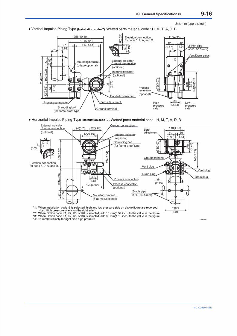
8/9/2019 YOKOGAWA TRANSMITTERS9(EJX110A, EJX120A, EJX130A, EJX310A, EJX430A, and EJX440A)
http://slidepdf.com/reader/full/yokogawa-transmitters9ejx110a-ejx120a-ejx130a-ejx310a-ejx430a-and-ejx440a 64/78
<9. General Specications> 9-16
IM 01C25B01-01E
Unit: mm (approx. inch)
54
(2.13)6
(0.24)
Electrical connectionfor code 5, 9, A, and D.
Electrical connectionfor code 5, 9, A, and D.
5 4
( 2 .
1 3 )
6 ( 0 . 2
4 )
Horizontal Impulse Piping Type (Installation code -9), Wetted parts material code : H, M, T, A, D, B
*1: When Installation code -8 is selected, high and low pressure side on above figure are reversed.(i.e. High pressure side is on the right side.)
*2: When Option code K1, K2, K5, or K6 is selected, add 15 mm(0.59 inch) to the value in the figure.*3: When Option code K1, K2, K5, or K6 is selected, add 30 mm(1.18 inch) to the value in the figure.*4: 15 mm(0.59 inch) for right side high pressure.
Vertical Impulse Piping Type (Installation code -7), Wetted parts material code : H, M, T, A, D, B
Integral indicator
(optional)
External indicator Conduit connection
(optional)
Mounting bracket
(Flat-type,optional)
Process connection
Process connector
(optional)
Conduit connection72(2.83)94(3.70)
1 2 4 ( 4 . 8
8 )
1 5 9 ( 6 .
2 6 )
4 7
( 1 .
8 5 )
1 9 4 ( 7 . 6
4 )
125(4.92)
46(1.81)
95(3.75)
Ground terminal
Zeroadjustment
Vent plug
2-inch pipe
(O.D. 60.5 mm)
Drain plug
1 4 3 ( 5 . 6
3 )
128*3
(5.04)
54
(2.13)
ø 7 8 ( 3 . 0
7 )
ø 7 0
( 2 . 7
6 )
39
(1.54)
110(4.33)
9*4
(0.35)
Vent plug
Drain plug
Shrouding bolt
(for flame-proof type)
Vent/Drain plugs
2-inch pipe
(O.D. 60.5 mm)
1 4 8 ( 5 . 8
3 ) * 2
54
(2.13)
12
(0.47)
110(4.33)
ø 7 8 ( 3 . 0
7 )
ø 7 0
( 2
. 7 6
)
39
(1.54)
Process connection
Mounting bracket
(L-type,optional)
Conduit connection
Integral indicator
(optional)
External indicator Conduit connection
(optional)
7 2 ( 2 . 8
3 )
1 0 2 ( 4 . 0
2 )
2 3 4 ( 9 . 2
1 )
5 2
( 2 . 0
5 )
256(10.10)
143(5.63)
194(7.64)
97
(3.82)
9 5
( 3 .
7 4 )
4 6
( 1 . 8
1 )
Zero adjustment
Ground terminalShrouding bolt
(for flame-proof type)
Highpressureside
Lowpressureside
F0905.ai
(optional)
Processconnector

8/9/2019 YOKOGAWA TRANSMITTERS9(EJX110A, EJX120A, EJX130A, EJX310A, EJX430A, and EJX440A)
http://slidepdf.com/reader/full/yokogawa-transmitters9ejx110a-ejx120a-ejx130a-ejx310a-ejx430a-and-ejx440a 65/78
<9. General Specications> 9-17
IM 01C25B01-01E
Unit: mm (approx. inch)
54
(2.13)6
(0.23)
129(5.08)
117(4.61)
54
(2.13)
ø 7 8 ( 3 . 0
7 )
ø 7 0
( 2
. 7 6 )
39
(1.54)
12
(0.47)
110(4.33)
188(7.40)95(3.74)
79
(3.11)
1 0 9 ( 4 . 2
9 )
2 1 9 ( 8 . 6
2 )
Integral indicator
(optional)
Ground terminal
Zeroadjustment
Extenal indicator Conduit connection
(optional)
Vent plug
2-inch pipe
(O.D. 60.5 mm)
Mounting bracket
(optional)
Process connection
Process connector
(optional)
Conduit connection
Shrouding bolt(for flame-proof type)
Bottom Process Connection (Installation code -B)
Lowpressureside
Highpressureside
Electrical connectionfor code 5, 9, A and D.
F0906.ai
54
(2.13)6
(0.24) ø 7 8 ( 3 . 0
7 )
ø 7 0
( 2
. 7 6 )
Integral indicator
(optional)
Ground terminal
ZeroadjustmentExternal indicator
Conduit connection
(optional)
Vent plug
Process connection
Process connector
(optional)
Conduit connection
Shrouding bolt
(for flame-proof type)
Universal Flange (Installation code -U)
Lowpressureside
Highpressureside
Electrical connectionfor code 5, 9, A, and D.
Drain plug
Drain plug
Drain plugVent plug
117*1
(4.61)
54
(2.13)
110(4.33)
12
(0.47)39
(1.54)
115(4.53)
41
(1.61)
58
(2.28)
67
(2.64)
1 7 5
( 6 . 8
9 )
1 2
9 ( 5 . 0
8 )
1
4 5 ( 5 . 7
1 )
95(3.74)

8/9/2019 YOKOGAWA TRANSMITTERS9(EJX110A, EJX120A, EJX130A, EJX310A, EJX430A, and EJX440A)
http://slidepdf.com/reader/full/yokogawa-transmitters9ejx110a-ejx120a-ejx130a-ejx310a-ejx430a-and-ejx440a 66/78
<9. General Specications> 9-18
IM 01C25B01-01E
Model EJX120AUnit: mm (approx. inch)
54
(2.13)6
(0.24)
Electrical connectionfor code 5, 9, A, and D.
Electrical connectionfor code 5, 9, A, and D.
5 4
( 2 . 1
3 )
6 ( 0 . 2
4 )
Horizontal Impulse Piping Type (Installation code -9)
*1: When Installation code 8 is selected, high and low pressure side on above figure are reversed.(i.e. High pressure side is on the right side.)
*2: When Option code K1, K2, K5, or K6 is selected, add 15 mm(0.59 inch) to the value in the figure.*3: When Option code K1, K2, K5, or K6 is selected, add 30 mm(1.18 inch) to the value in the figure.
Vertical Impulse Piping Type (Installation code -7)
Integral indicator
(optional)
Extenal indicator Conduit connection
(optional)
Mounting bracket
(Flat-type,optional)
Process connection
Conduit connection72(2.83)94(3.70)
1 2 4 ( 4 . 8
8
)
1 5 9 ( 6 . 2
6 )
4 7
( 1 . 8
5 )
1 9 4 ( 7 .
6 4 )
125(4.92)
46
(1.81)
95(3.75)
Ground terminal
Zeroadjustment
Vent plug
2-inch pipe
(O.D. 60.5 mm)
Drain plug
1 4 3 ( 5 . 6
3 )
128*3
(5.04)
54
(2.13)
ø 7 8 ( 3 . 0
7 )
ø 7 0
( 2 . 7
6 )
39
(1.54)
110(4.33)
12
(0.47)
Vent plug
Drain plug
Shrouding bolt
(for flame-proof type)
Vent/Drain plugs
2-inch pipe
(O.D. 60.5 mm)
1 4 8 ( 5 .
8 3 ) * 2
54
(2.13)
12
(0.47)
110(4.33)
ø 7 8 ( 3 . 0
7 )
ø 7 0
( 2
. 7 6
)
39
(1.54)
Process connection
Mounting bracket
(L-type,optional)
Conduit connection
Integral indicator
(optional)
Extenal indicator Conduit connection
(optional)
7 2 ( 2 .
8 3 )
1 0 2 ( 4 .
0 2 )
2 3 4 ( 9 . 2
1 )
5 2
( 2 . 0
5 )
256(10.10)
143(5.63)
194(7.64)
97
(3.82)
9 5
( 3 . 7
4 )
4 6
( 1 . 8
1 )
Zero adjustment
Ground terminalShrouding bolt
(for flame-proof type)
Highpressureside
Lowpressureside
Process connector (optional)
Process connector
(optional)
F0908.ai

8/9/2019 YOKOGAWA TRANSMITTERS9(EJX110A, EJX120A, EJX130A, EJX310A, EJX430A, and EJX440A)
http://slidepdf.com/reader/full/yokogawa-transmitters9ejx110a-ejx120a-ejx130a-ejx310a-ejx430a-and-ejx440a 67/78
<9. General Specications> 9-19
IM 01C25B01-01E
Unit: mm (approx. inch)
54
(2.13)6
(0.24) ø 7 8 ( 3 . 0
7 )
ø 7 0
( 2
. 7 6 )
Integral indicator
(optional)
Ground terminal
Zeroadjustment
External indicator Conduit connection
(optional)
Vent plug
Process connection
Process connector
(optional)
Conduit connection
Shrouding bolt
(for flame-proof type)
Universal Flange (Installation code -U)
Lowpressureside
Highpressureside
Electrical connectionfor code 5, 9, A, and D.
Drain plug
Drain plug
Drain plug
Vent plug
54
(2.13)
110(4.33)
12
(0.47)
39
(1.54)
1 9 4 ( 7 .
6 4 )
1 4 3 ( 5 . 6 3
)
1 5 9 ( 6 . 2
6 )
95(3.74)
*1: When Option code K1, K2, K5, or K6 is selected, add 30 mm(1.18 inch) to the value.
46
(1.81)
125(4.92) 128(5.04)*1
63
(2.48)
72
(2.83)
F0909.ai

8/9/2019 YOKOGAWA TRANSMITTERS9(EJX110A, EJX120A, EJX130A, EJX310A, EJX430A, and EJX440A)
http://slidepdf.com/reader/full/yokogawa-transmitters9ejx110a-ejx120a-ejx130a-ejx310a-ejx430a-and-ejx440a 68/78
<9. General Specications> 9-20
IM 01C25B01-01E
Model EJX130AUnit: mm (approx. inch)
54
(2.13)6
(0.24)
Extenal indicator Conduit connection
(optional)
Process connectionZero adjustment
Ground terminal
Mounting bracket(L-type,optional)
Conduit connection
Integral indicator
(optional)
Vent/Drain plugs
Vertical Impulse Piping Type (Installation code -7)
143(5.63)
197(7.76)
256(10.1)
97(3.82)
9 5
( 3
. 7 4 )
9 3
( 3
. 6 6 )
1 2 4
( 4
. 8 8 )
2 7 7 ( 1 0
. 9 )
5 2
( 2
. 0 5 )
39
(1.54)
110(4.33)
ø 7 0 ( 2 .
7 6 )
1 9 2 ( 7
. 5 6 ) * 2
ø 7 8 ( 3
. 0 7 )
132(5.2)
9
(0.35)
Lowpressureside
Highpressureside
2-inch pipe
(O.D. 60.5 mm)
54
(2.13)
6 ( 0
. 2 4 )
5 4
( 2
. 1 3 )
Electrical connectionfor code 5, 9, A, and D.
1 5 9 ( 6
. 2 6 )
1 2 4 ( 4
. 8
8 )
4 7
( 1
. 8 5 )
Mounting bracket
(Flat-type,optional)
Conduit connection
(optional)
Extenal indicator Conduit connection
Integral indicator
(optional)
Processconnection
Shrouding bolt
(for flame-proof type)
Shrouding bolt
(for flame-proof type)
(optional)
Processconnector
Electrical connectionfor code 5, 9, A, and D.
1 9 7 ( 7
. 7 6 )
95(3.74)
116(4.57)
169(6.65)
68(2.68)
93(3.66)
Drain plug*4
2-inch pipe(O.D. 60.5 mm)
Vent plug*4
Zeroadjustment
Ground terminal
Drain plug*4
Vent plug*4
54(2.13) Lowpressureside
High*1
pressureside
110(4.33)
9*5
(0.35)
39
(1.54)
ø 7 0
( 2
. 7 6 )
1 4 3 ( 5
. 6 3 )
ø 7 8 ( 3
. 0 7 )
154(6.06)*3
Horizontal Impulse Piping Type (Installation code -9)
*1: When Installation code -8 is selected, high and low pressure side on above figure are reversed.(i.e. High pressure side is on the right side.)
*2: When Option code K1, K2, K5, or K6 is selected, add 15 mm(0.59 inch) to the value in the figure.*3: When Option code K1, K2, K5, or K6 is selected, add 30 mm(1.18 inch) to the value in the figure.*4: Not available when /GS is specified.*5: 15mm (0.59 inch) for right side high pressure.
F0910.ai
Process connector (optional)

8/9/2019 YOKOGAWA TRANSMITTERS9(EJX110A, EJX120A, EJX130A, EJX310A, EJX430A, and EJX440A)
http://slidepdf.com/reader/full/yokogawa-transmitters9ejx110a-ejx120a-ejx130a-ejx310a-ejx430a-and-ejx440a 69/78
<9. General Specications> 9-21
IM 01C25B01-01E
Unit: mm (approx. inch)
54
(2.13)6
(0.24) ø 7
8 ( 3 . 0
7 )
ø 7 0
( 2
. 7 6 )
Integral indicator
(optional)
Ground terminal
Zeroadjustment
External indicator Conduit connection
(optional)
Vent plug
Process connection
Process connector
(optional)
Conduit connection
Shrouding bolt
(for flame-proof type)
Universal Flange (Installation code -U)
Lowpressureside
Highpressureside
Electrical connectionfor code 5, 9, A, and D.
Drain plug
Drain plug
Drain plugVent plug
54
(2.13)
110(4.33)
9
(0.35)
39
(1.54)
1 9 7 ( 7 . 7
6 )
1 4 3 ( 5 . 6
3
)
1 5 9 ( 6 . 2
6 )
*1: When Option code K1, K2, K5, or K6 is selected, add 30 mm(1.18 inch) to the value.
85(3.35) 93(3.66)
68
(2.68)
169(6.65)
95(3.74)
154(6.06)*1
F0911.ai

8/9/2019 YOKOGAWA TRANSMITTERS9(EJX110A, EJX120A, EJX130A, EJX310A, EJX430A, and EJX440A)
http://slidepdf.com/reader/full/yokogawa-transmitters9ejx110a-ejx120a-ejx130a-ejx310a-ejx430a-and-ejx440a 70/78
<9. General Specications> 9-22
IM 01C25B01-01E
Model EJX310AUnit: mm (approx. inch)
9 5 ( 3 . 7
4 )
242(9.53)
175(6.89)
129(5.08)97
(3.82)
2 2 3 ( 8 . 7
8 )
5 2
( 2 .
0 5 )
9 7 ( 3 . 8
2 )
4 1
( 1 .
6 1 )
6 7 ( 2 . 6
4 )
Electrical connectionfor code 5, 9, A, and D.
(optional)
Extenal indicator Conduit connection
Integral indicator
(optional)
Zero adjustment
Ground terminal(optional)
Mounting bracket
(L-type,optional)
Process connector
Conduit connection
110(4.33)
ø 7 8 ( 3 . 0
7 )
ø 7 0 ( 2
. 7 6 )
39
(1.54)
12
(0.47)
1 3 8 ( 5 .
4 3 ) * 2
27
(1.06)
5 4
( 2 . 1
3 )
2-inch pipe
(O.D. 60.5 mm)
Vent/Drain
plugs
6 ( 0 . 2
4 )
54
(2.13)6
(0.24)
1 7 5 ( 6 . 8
9 )
1 4 5 ( 5 . 7
1 )
1 2 4 ( 4 . 8
8 )
4 7
( 1 . 8
5 )
95(3.74)
89(3.50)
115(4.53)
41
(1.61)
110(4.33)
12
(0.47)
39
(1.54)
ø 7 0
( 2 . 7
6 )
1 2 9 ( 5 . 0
8 )
ø 7 8 ( 3 .
0 7 )
59*2
(2.32)
67
(2.64)
Drain plug*3
2-inch pipe(O.D. 60.5 mm)
Vent plug*3
Zeroadjustment
Ground terminal
Mounting bracket
(Flat-type,optional)
Electrical connectionfor code 5, 9, A, and D.
Conduitconnection
(optional)
Extenal indicator Conduit connection
Integral indicator
(optional)
Processconnection
27(1.06)
Horizontal Impulse Piping Type (Installation code -9)
*1: When Installation code -8 is selected, high and low pressure side on above figure are reversed.
(i.e. High pressure side is on the right side.)
*2: When Option code K1, K2, K5, or K6 is selected, add 15 mm(0.59 inch) to the value in the figure.
*3: Not available when /GS is specified.
Vertical Impulse Piping Type (Installation code -7)
Highpressureside
Lowpressureside
Lowpressure
side
Highpressureside
Shrouding bolt
(for flame-proof type)
Shrouding bolt
(for flame-proof type)
(optional)
Processconnector
F0912.ai

8/9/2019 YOKOGAWA TRANSMITTERS9(EJX110A, EJX120A, EJX130A, EJX310A, EJX430A, and EJX440A)
http://slidepdf.com/reader/full/yokogawa-transmitters9ejx110a-ejx120a-ejx130a-ejx310a-ejx430a-and-ejx440a 71/78
<9. General Specications> 9-23
IM 01C25B01-01E
Unit: mm (approx. inch)
54
(2.13)6
(0.24)
129
(5.08)
59
(2.32)
27
(1.06)
ø 7 8 ( 3 . 0
7 )
ø 7 0
( 2
. 7 6 )
39
(1.54)
12
(0.47)
110(4.33)
188(7.40)95(3.74)
79
(3.11)
1 0 9 ( 4 . 2
9 )
2 1 9 ( 8 . 6
2 )
Integral indicator
(optional)
Ground terminal
Zeroadjustment
Extenal indicator Conduit connection
(optional)
Vent plug
2-inch pipe
(O.D. 60.5 mm)
Mounting bracket
(optional)
Process connection
Conduit connection
Shrouding bolt(for flame-proof type)
Process connector
(optional)
Bottom Process Connection (Installation code -B)
Lowpressureside
Highpressureside
Electrical connectionfor code 5, 9, A, and D.
F0913.ai
54
(2.13)6
(0.24) ø 7 8 ( 3 .
0 7 )
ø 7 0
( 2
. 7 6 )
Integral indicator
(optional)
Ground terminal
ZeroadjustmentExternal indicator
Conduit connection
(optional)
Vent plug
Process connection
Process connector
(optional)
Conduit connection
Shrouding bolt
(for flame-proof type)
Universal Flange (Installation code -U)
Lowpressureside
Highpressureside
Electrical connectionfor code 5, 9, A, and D.
Drain plug
Drain plug
59*1
(2.32)
110(4.33)
12
(0.47)39
(1.54)
115(4.53)
41
(1.61)
58
(2.28)
67
(2.64)
1 7 5 ( 6
. 8 9 )
1 2 9 ( 5 .
0 8 )
1 4 5
( 5 .
7 1 )
95(3.74)
*1: When Option code K1, K2, K5, or K6 is selected, add 15 mm(0.59 inch) to the value. F0914.ai

8/9/2019 YOKOGAWA TRANSMITTERS9(EJX110A, EJX120A, EJX130A, EJX310A, EJX430A, and EJX440A)
http://slidepdf.com/reader/full/yokogawa-transmitters9ejx110a-ejx120a-ejx130a-ejx310a-ejx430a-and-ejx440a 72/78
<9. General Specications> 9-24
IM 01C25B01-01E
Model EJX430AUnit: mm (approx. inch)
9 5 ( 3 .
7 4 )
242(9.53)
175(6.89)
129(5.08)97
(3.82)
2 2 3 ( 8 . 7
8 )
5 2
( 2 . 0
5 )
9 7 ( 3 .
8 2 )
4 1
( 1 .
6 1 )
6 7 ( 2 . 6
4 )
Electrical connectionfor code 5, 9, A, and D.
(optional)
External indicator Conduit connection
Integral indicator
(optional)
Zero adjustment
Ground terminal
Mounting bracket
(L-type,optional)
Process connection
Conduit connection
110(4.33)
ø 7 8 ( 3 . 0
7 )
ø 7 0 ( 2
. 7 6 )
39
(1.54)
12
(0.47)
1 3 8 ( 5 . 4
3 ) * 2
27
(1.06)
5 4
( 2 . 1
3 )
2-inch pipe
(O.D. 60.5 mm)
Vent/Drain
plugs
6 ( 0 .
2 4 )
54
(2.13)6
(0.24)
1 7 5 ( 6 . 8
9 )
1 4 5 ( 5 .
7 1 )
1 2 4 ( 4 . 8
8 )
4 7
( 1 . 8
5 )
95(3.74)
89(3.50)
115(4.53)
41
(1.61)
110(4.33)
12
(0.47)
39
(1.54)
ø 7 0
( 2 . 7
6 )
1 2 9 ( 5 . 0
8 )
ø 7 8 ( 3 . 0
7 )
59*2
(2.32)
67
(2.64)
Drain plug*3
2-inch pipe(O.D. 60.5 mm)
Vent plug*3
Zeroadjustment
Ground terminal
Mounting bracket
(Flat-type,optional)
Electrical connectionfor code 5, 9, A, and D.
Conduitconnection
(optional)
External indicator Conduit connection
Integral indicator
(optional)
Processconnection 27(1.06)
Horizontal Impulse Piping Type (Installation code -9), Wetted parts material code : S
*1: When Installation code -8 is selected, high and low pressure side on above figure are reversed.
(i.e. High pressure side is on the right side.)
*2: When Option code K1, K2, K5, or K6 is selected, add 15 mm(0.59 inch) to the value in the figure.
*3: Not available when /GS is specified.
Vertical Impulse Piping Type (Installation code -7), Wetted parts material code : S
Highpressureside
Lowpressureside
Lowpressure
side
Highpressure
side
Shrouding bolt
(for flame-proof type)
Shrouding bolt
(for flame-proof type)
Open to atmosphere ø5(0.20)
Open to atmosphere
ø10(0.39)
F0915.ai
(optional)
Process connector
(optional)
Processconnector

8/9/2019 YOKOGAWA TRANSMITTERS9(EJX110A, EJX120A, EJX130A, EJX310A, EJX430A, and EJX440A)
http://slidepdf.com/reader/full/yokogawa-transmitters9ejx110a-ejx120a-ejx130a-ejx310a-ejx430a-and-ejx440a 73/78
<9. General Specications> 9-25
IM 01C25B01-01E
Unit: mm (approx. inch)
54
(2.13)6
(0.24)
Electrical connectionfor code 5, 9, A, and D.
Electrical connectionfor code 5, 9, A, and D.
5 4
( 2 . 1
3 )
6 ( 0 . 2
4 )
Horizontal Impulse Piping Type (Installation code -9), Wetted parts material code : H, M, T, A, D, B
*1: When Installation code -8 is selected, high and low pressure side on above figure are reversed.(i.e. High pressure side is on the right side.)
*2: When Option code K1, K2, K5, or K6 is selected, add 15 mm(0.59 inch) to the value in the figure.
Vertical Impulse Piping Type (Installation code -7), Wetted parts material code : H, M, T, A, D, B
Integral indicator
(optional)
External indicator Conduit connection
(optional)
Mounting bracket
(Flat-type,optional)
Process connection
Process connector
(optional)
Conduit connection72(2.83)94(3.70)
1 2 4 ( 4 . 8
8
)
1 5 9 ( 6 . 2
6 )
4 7
( 1 . 8
5 )
1 9 4 ( 7 . 6
4 )
125(4.92)
46
(1.81)
95(3.75)
Ground terminal
Zeroadjustment
Vent plug
2-inch pipe
(O.D. 60.5 mm)
Drain plug
1 4 3 ( 5 . 6
3 )
64*2
(2.52)
54
(2.13)
ø 7 8 ( 3 . 0
7 )
ø 7 0
( 2 . 7
6 )
39
(1.54)
110(4.33)
12
(0.47)
Open to atmosphere ø10(0.39)
Open to atmosphere
ø5(0.20)
Shrouding bolt
(for flame-proof type)
Vent/Drain plugs
2-inch pipe
(O.D. 60.5 mm)
1 4 8 ( 5 . 8
3 ) * 2
27
(1.06)
12
(0.47)
110(4.33)
ø 7 8 ( 3 . 0
7 )
ø 7 0
( 2
. 7 6
)
39
(1.54)
Process connection
Mounting bracket
(L-type,optional)
Conduit connection
Integral indicator
(optional)
External indicator Conduit connection
(optional)
7 2 ( 2 .
8 3 )
1 0 2 ( 4 .
0 2 )
2 3 4 ( 9 . 2
1 )
5 2
( 2 . 0
5 )
256(10.10)
143(5.63)
194(7.64)
97
(3.82)
9 5
( 3 . 7
4 )
4 6
( 1 . 8
1 )
Zero adjustment
Ground terminalShrouding bolt
(for flame-proof type)
Highpressureside
Lowpressureside
F0916.ai
Processconnector (optional)

8/9/2019 YOKOGAWA TRANSMITTERS9(EJX110A, EJX120A, EJX130A, EJX310A, EJX430A, and EJX440A)
http://slidepdf.com/reader/full/yokogawa-transmitters9ejx110a-ejx120a-ejx130a-ejx310a-ejx430a-and-ejx440a 74/78
<9. General Specications> 9-26
IM 01C25B01-01E
Unit: mm (approx. inch)
54
(2.13)6
(0.24)
129
(5.08)
59
(2.32)
27
(1.06)
ø 7 8 ( 3 . 0
7 )
ø 7 0
( 2
. 7 6 )
39
(1.54)
12
(0.47)
110(4.33)
188(7.40)95(3.74)
79
(3.11)
1 0 9 ( 4 . 2
9 )
2 1 9 ( 8 . 6
2 )
Integral indicator
(optional)
Ground terminal
Zeroadjustment
Extenal indicator Conduit connection
(optional)
Vent plug2-inch pipe
(O.D. 60.5 mm)
Mounting bracket
(optional)
Process connection
Process connector
(optional)
Conduit connection
Shrouding bolt(for flame-proof type)
Bottom Process Connection (Installation code -B)
Lowpressureside
Highpressureside
Electrical connectionfor code 5, 9, A, and D.
Open toatmosphere
ø10(0.39)
F0917.ai
54
(2.13)6
(0.24) ø 7 8 ( 3 . 0
7 )
ø 7 0
( 2
. 7 6 )
Integral indicator
(optional)
Ground terminal
ZeroadjustmentExternal indicator
Conduit connection
(optional)
Vent plug
Process connection
Process connector
(optional)
Conduit connection
Shrouding bolt
(for flame-proof type)
Universal Flange (Installation code -U)
Lowpressureside
Highpressureside
Electrical connectionfor code 5, 9, A, and D.
Drain plug
Drain plug
59*1
(2.32)
110(4.33)
12
(0.47)39
(1.54)
115(4.53)
41
(1.61)
58
(2.28)
67
(2.64)
1
7 5 ( 6 . 8
9 )
1 2 9 ( 5 .
0 8 )
1 4 5 ( 5 . 7
1 )
95(3.74)
*1: When Option code K1, K2, K5, or K6 is selected, add 15 mm(0.59 inch) to the value.
Open to atmosphere
(ø5)
F0918.ai

8/9/2019 YOKOGAWA TRANSMITTERS9(EJX110A, EJX120A, EJX130A, EJX310A, EJX430A, and EJX440A)
http://slidepdf.com/reader/full/yokogawa-transmitters9ejx110a-ejx120a-ejx130a-ejx310a-ejx430a-and-ejx440a 75/78
<9. General Specications> 9-27
IM 01C25B01-01E
Model EJX440AUnit: mm (approx. inch)
Electrical connectionfor code 5, 9, A and D.
5 4
( 2 . 1
3 )
6 ( 0 . 2
4 )
54
(2.13)6
(0.24)
Electrical connectionfor code 5, 9, A and D.
F0919.ai
Open toatmospher ø9(0.35)
Vent/Drain plugs
2-inch pipe
(O.D. 60.5 mm)
Highpressureside
Lowpressureside
1 8 2 ( 7 . 1
7 ) * 2
ø 7 0
( 2
. 7 6
)
ø 7 8 ( 3 . 0
7 )
Extenal indicator Conduit connection
(optional)
Integral indicator (optional)
Zero adjustment
Ground terminal
Mounting bracket
(L-type,optional)
Process connection
Conduit connection
1 1 9 ( 4 . 6
9 )
8 8 ( 3 . 4
6 )
5 2
( 2 . 0
5 )
129(5.08)97
(3.82)
6 3
( 2 . 4
8 )
2 6 7 ( 1 0 . 5
)
175(6.89)
242(9.53)
9 5
( 3 .
7 4 )
27
(1.06)
110(4.33)
39
(1.54)
12
(0.47)
120(4.72)
Shrouding bolt
(for flame-proof type)
Integral indicator
(optional)
Extenal indicator Conduit connection
(optional)
Vent plug*3
Drain plug*3
Mounting bracket
(Flat-type,optional)
Process connection
Process connector
(optional)
Conduit connection
1 2 4 ( 4 . 8 8
)
1 4 5 ( 5 . 7
1 )
4 7
( 1 .
8 5 )
88(3.46)
159(6.26)
63
(2.48)
95(3.74)
1 7 5 ( 6 . 8
9 )
111(4.37)
Open to
atmosphere ø5(0.20)
Groundterminal
Zeroadjustment
2-inch pipe
(O.D. 60.5 mm)
Highpressureside
Lowpressureside
ø 7 8 ( 3 . 0
7 )
ø 7 0
( 2 . 7
6 )
39
(1.54)
110(4.33)
12
(0.47)
1 2 9 ( 5 . 0
8 )
27(1.06)
70*2
(2.76)
Shrouding bolt
(for flame-proof type)
Horizontal Impulse Piping Type (Installation code -9)
*1: When Installation code -8 is selected, high and low pressure side on above figure are reversed.
(i.e. High pressure side is on the right side.)
*2: When Option code K1, K2, K5, or K6 is selected, add 15 mm(0.59 inch) to the value in the figure.
*3: Not available when /GS is specified.
Vertical Impulse Piping Type (Installation code -7)
Process connector
(optional)

8/9/2019 YOKOGAWA TRANSMITTERS9(EJX110A, EJX120A, EJX130A, EJX310A, EJX430A, and EJX440A)
http://slidepdf.com/reader/full/yokogawa-transmitters9ejx110a-ejx120a-ejx130a-ejx310a-ejx430a-and-ejx440a 76/78
<9. General Specications> 9-28
IM 01C25B01-01E
Unit: mm (approx. inch)
54
(2.13)6
(0.24) ø 7 8
( 3 . 0
7 )
ø 7 0
( 2
. 7 6 )
Integral indicator
(optional)
Ground terminal
Zeroadjustment
External indicator Conduit connection
(optional)
Vent plug
Process connection
Process connector
(optional)
Conduit connection
Shrouding bolt
(for flame-proof type)
Universal Flange (Installation code -U)
Lowpressureside
Highpressureside
Electrical connectionfor code 5, 9, A, and D.
Drain plug
Drain plug
12
(0.47)
39
(1.54)
1 7 5 ( 6 .
8 9 )
1 2 9 ( 5 . 0
8 )
1 4 5 ( 5 . 7
1 )
*1: When Option code K1, K2, K5, or K6 is selected, add 15 mm(0.59 inch) to the value.
80
(3.15)
88
(3.46)
63
(2.48)
159(6.26)
95(3.74)
110(4.33)
27
(1.06)
70*1
(2.76)
Open to atmosphere
(ø5)
F0920.ai
SUPPLY
CHECK
or
ALARM
+ –
+ –
Terminal Configuration
Power supply and output terminal
External indicator (ammeter) terminal*1*2
or
Status contact output terminal*2
(when /AL is specified)
Ground terminal
Communicationterminals (BT200 etc.)connection hook
Terminal Wiring
*1: When using an external indicator or check meter, the internal
resistance must be 10 Ω or less. A check meter or indicator
cannot be connected when /AL option is specified.
*2: Not available for fieldbus communication type.
Check meterconnection hook*1*2
SUPPLY +
SUPPLY – CHECK – or ALARM –
CHECK + or
ALARM +
+ –
F0921.ai
< Factory Setting >
Tag Number As specied in order Amplier Damping *2 ‘2 sec.’ or as specied in order Output Mode ‘Linear’ unless otherwise specied in order Calibration Range Lower Range Value As specied in order Calibration Range Upper Range Value As specied in order Calibration Range Units Selected from the followings. Only one unit can be specied.
[Differential/gauge pressure transmitter]mmH2O, mmH2O(68°F), mmAq, mmWG, mmHg, Pa, hPa, kPa, MPa, mbar,bar, gf/cm2, kgf/cm2, inH2O, inH2O(68°F), inHg, ftH2O, ftH2O(68°F) or psi.[Absolute pressure transmitter]torr, Pa abs, hPa abs, kPa abs, MPa abs, mbar abs, bar abs, mmH2O abs,
mmH2O abs(68°F), mmHg abs, gf/cm2 abs, kgf/cm2 abs, inH2O abs,inH2O abs(68°F), inHg abs, ftH2O abs, ftH2O abs(68°F) , atm, or psia.
Display Setting Designated differential pressure value specied in order. (%, Engineeringunit or user scaled value.) Display mode 'Linear' or 'Square root' is also asspecied in order.
Static Pressure Display Range*1 '0 to 25 MPa' for M, H, and V capsule of EJX110A, '0 to 16 MPa' for L capsule,and '0 to 32 MPa' for EJX130A.Display unit is selectable from the units listed in above 'Calibration RangeUnits'.
*1: For differential pressure transmitters only.*2: To specify these items at factory, /CA or /CB option is required.

8/9/2019 YOKOGAWA TRANSMITTERS9(EJX110A, EJX120A, EJX130A, EJX310A, EJX430A, and EJX440A)
http://slidepdf.com/reader/full/yokogawa-transmitters9ejx110a-ejx120a-ejx130a-ejx310a-ejx430a-and-ejx440a 77/78
i
IM 01C25B01-01E
Revision Information Title : EJX110A, EJX120A, EJX130A, EJX310A, EJX430A, and EJX440A
Differential Pressure and Pressure Transmitters
Manual No. : IM 01C25B01-01E
Edition Date Page Revised Item
1st Mar. 2004 — New publication2nd Apr. 2004 — Revise words and phrases.
2-6 2.9.3 • Correct Ambient temperature –60 → –504-4 4.5 • Change the description of rotation angle.8-3 8.4 • Add Allen wrench nominal 3mm to Table 8.4.1.
3rd Feb. 2005 — Re-number gure and table title.i Add subsection 6.3.5.ii Add note for Safety Transmitter.
1-1 1. • Add note for Fieldbus communication type.1-3 1.1 • Add (f) Modication.2-3 2.9 • Add NOTE for eldbus communication type.2-5 2.9.2 • Modify descriptions and instructions for CSA certication2-72-8
2.9.3 • Correct number in Note 4. 10 MINUTES → 5 MINUTES• Delete WARNING on non-incendive power supply.• Correct number for Electrical data Ci. 6 nF → 10 nF
3-1 3. • Correct label of the switch in the gure. N → E, Y → D• Add descriptions in Note 2.
4-3 4.4.1 • Add description about process connector in 3).4-4 4.6 • Add section 4.6.6-1 6.3.1, 6.3.2 • Add limitation/note when /AL is specied.6-2 6.3.4 • Add limitation when /AL is specied.6-2 6.3.5 • Add subsection 6.3.5.7-3 7.2.1 • Add descriptions about zero adjustment.
9-1, 9-2 9.1 • Add notes for FOUNDATION eldbus communication type.• Add capsule code H.9-4, 9-5 9.2 • Add output signal code -F and capsule code H.
9-6 9.3 • Add CSA approvals and note *2 and *39-8 9.4 • Add note *3.9-10 9.4 • Add notes for /AL and FOUNDATION Fieldbus.
4th Sep. 2005 1-1 1. • Add model names to the manual coverage.2-3 to 2-8 2. • Add applicable standard and certicate number for each
approval.2-11 2.10 • Change australian reference standard.2-11 2.11 • Add descriptions for PED.2-12 2.11 • Add section 2.12.4-1 4.1 • Add model name.
4-2 4.3 • Add table 4.1.8-5 8.4.3 • Add table for torque.
Add notes for reassembling EJX130A and EJX440A.8.4.4 • Add table for torque.
9-1 to 9-18 9. • Add specications, codes, and dimensions for EJX130A,EJX310A and EJX440A.
5th July 2006 2-8- 2.9.3 • Change applicable standards for ATEX type n.—6th Nov. 2007 1-1 1. • Add model code table.
2-3 2.9 • Add note for EJX130A.9-10 9.3 • Add note for EJX130A.9-15 9.4 • Modify dimensions of EJX130A. A-1 APPENDIX 1. Add "EJX130A ADDITIONAL INFORMATION."

8/9/2019 YOKOGAWA TRANSMITTERS9(EJX110A, EJX120A, EJX130A, EJX310A, EJX430A, and EJX440A)
http://slidepdf.com/reader/full/yokogawa-transmitters9ejx110a-ejx120a-ejx130a-ejx310a-ejx430a-and-ejx440a 78/78
ii
Edition Date Page Revised Item
7th Feb. 2008 — Change of the style code, add EJX120A.General • Change the gure of amplier housing.
1-1 1 • Add style code table.2-1 2.1 • Update the Figure 2.2.2-5 2.9.1 • Add code /V1U.2-6 2.9.2 • Revise information for CSA Explosionproof type.
2-7 2.9.2 • Add code /V1U.2-8 2.9.3 • Revise information for KEMA ameproof type. Add code /V1U.2-9 2.9.3 • Revise Figure in (2) Electrical connection and (6) Nameplate.2-10 2.9.4 • Revise information for IECEx ameproof type.
9-1 to 9-3 9.1 • Add information for EJX120A.9-5 to 9-10 9.2 • Add new sufx codes for 316 SST blind plugs and brackets.
Add EJX120A.9-11 9.3 • Remove /KF2 and /KU2. Add /KF21, /KU21, /SF2 and /V1U.9-12 • Add /HC.
9-14 to 9-20 9.4 • Revise external dimensions.Add EJX120A.— • Remove Appendix 1 'Additional Information for EJX130A.'
8th June 2008 2-6 2.9.2 • Correct certication number.
2-8 2.9.3 • Revise applicabble standards for ATEX Type n.2-11 2.11 • Add EJX110A V capsule, wetted parts matterial code S andEJX310A L capsule.
4-1 4.2 • Add information of Universal ange.8-5 8.4.3 • Add wetted parts material code in the torque table.
9-1 to 9-27 9. • Add EJX110A V capsule, EJX110A/EJX430A wetted partsmaterial code H, M, T, A, D, and B, EJX310A L capsule andoption code /S1, and universal ange.
9-10 9.3 • Add statement of sealing certication for CSA approval.9th Aug. 2009 2-1 2.1 • Replace a name plate.
2-11 2.10 • Revise standards.2.11 • Revise information of PED.
9-4 to 9-9 9.2 • Modify descriptions of materials.
9-11 to 9-12 9.3 • Add /GS, /A1,and /DG6.9-13 to 9-26 9.4 • Correct errors. Add note for /GS.
10th Apr. 2010 2-4 to 2-118-19-49-12
2.98.39.19.3
• Add limitation of ambient temperature for /HE.• Add description for warm up time.• Add O-ring material.• Add /HE.
11th Mar. 2012 2-39-4
9-5 to 9-10
2.99.19.2
• Add note for blind plugs.• Change description for a plate material.• Add amplier housing code 3.