Workshop efterår 2010 - Aalborg Universitethomes.et.aau.dk/mma/energiteknik/slides/WS -...
43
Energimaskiner Workshop efterår 2010 1
Transcript of Workshop efterår 2010 - Aalborg Universitethomes.et.aau.dk/mma/energiteknik/slides/WS -...

Energimaskiner
Workshop
efterår 2010
1

Program
• 08:15-09:30 Forelæsning
• 09:30-14:00 Miniprojekt i grupper
• 14:00-15:00 Fremlæggelse i plenum
2

Forlæsning
• Carnot
• Sterling (m. demo)
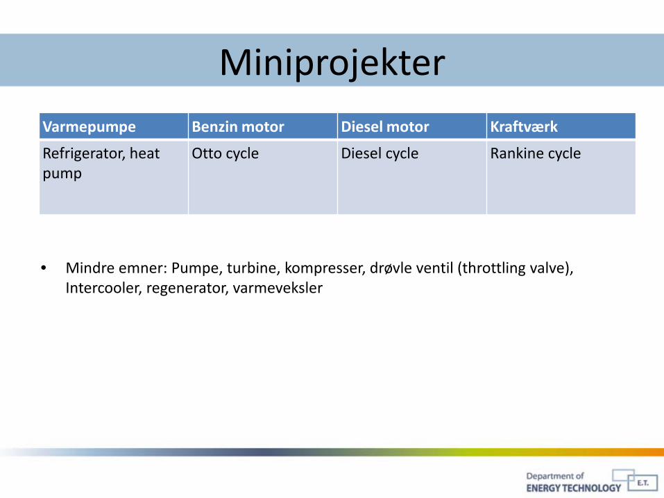
MiniprojekterVarmepumpe Benzin motor Diesel motor Kraftværk
Refrigerator, heat pump
Otto cycle Diesel cycle Rankine cycle
• Mindre emner: Pumpe, turbine, kompresser, drøvle ventil (throttling valve), Intercooler, regenerator, varmeveksler

Præsentation
• 10-30 min, 1-2 personer1. Beskrivelse af systemet væsentlige komponenter
2. Beskriv systemet i PV-diagram
3. Angiv typiske effektivitet
4. Andet…Fordele og ulemper…


First little history
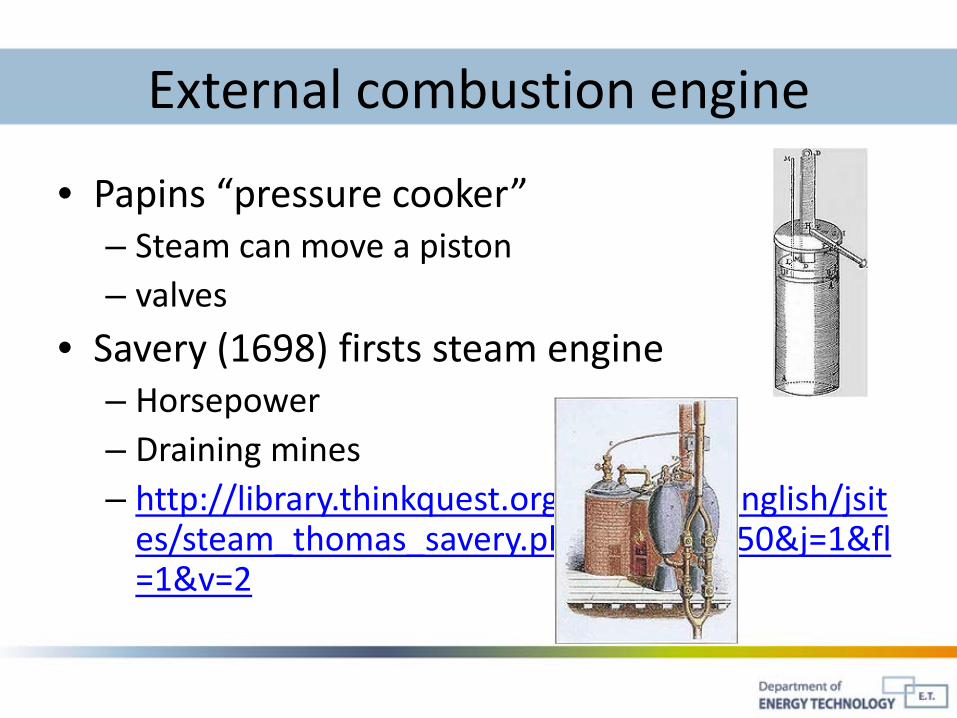
External combustion engine
• Papins “pressure cooker”– Steam can move a piston– valves
• Savery (1698) firsts steam engine– Horsepower– Draining mines– http://library.thinkquest.org/C006011/english/jsit
es/steam_thomas_savery.php3?f=2&b=50&j=1&fl=1&v=2
http://library.thinkquest.org/C006011/english/jsites/steam_thomas_savery.php3?f=2&b=50&j=1&fl=1&v=2�
http://library.thinkquest.org/C006011/english/jsites/steam_thomas_savery.php3?f=2&b=50&j=1&fl=1&v=2�

External combustion engine
• Newcomens steam engine– 1712

External combustion engine
• Watts 2nd steam engine– Double piston stoke
– 1775
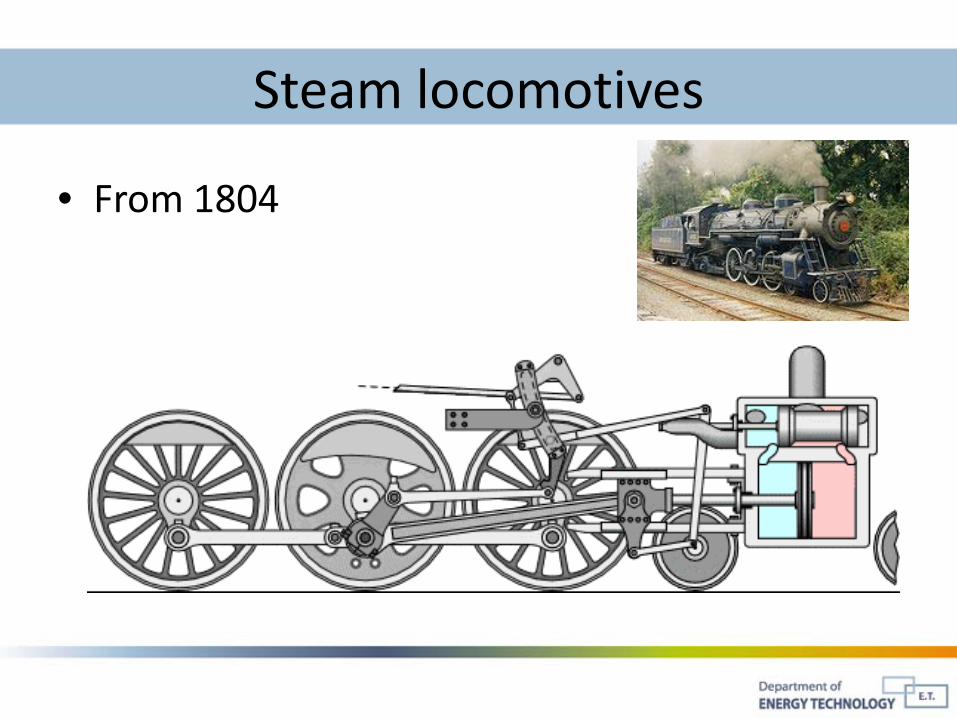
Steam locomotives
• From 1804

Sterling engines
• Sterling (1820)
• http://library.thinkquest.org/C006011/english/sites/stirling.php3?f=2&b=50&j=1&fl=1&v=2

Internal combustion engine
• Two stroke engine

Internal combustion engine
• 1862 Otto - two stroke
• 1879 Benz - first car
• 1892 Diesel – compression ignition
and many more people should be mentioned…

End of history lesson

Sterling engineStep 0. Thermal properties of air
Source: Peter Fette, http://www.stirling-fette.de/peter.htm#EN

Sterling engineStep 1. Add a work piston…
Source: Peter Fette, http://www.stirling-fette.de/peter.htm#EN

Sterling engineStep 2. Add a displacement “piston”…
Source: Peter Fette, http://www.stirling-fette.de/peter.htm#EN

Sterling engine
• Displacement Piston– Sufficient gab to allow air movement
– Should be as light as possible
– “piston” needs a transfer of work to move
– Creates two temperature zones in the cylinder
Cold zoneCooling ribs
Hot zoneHeat source
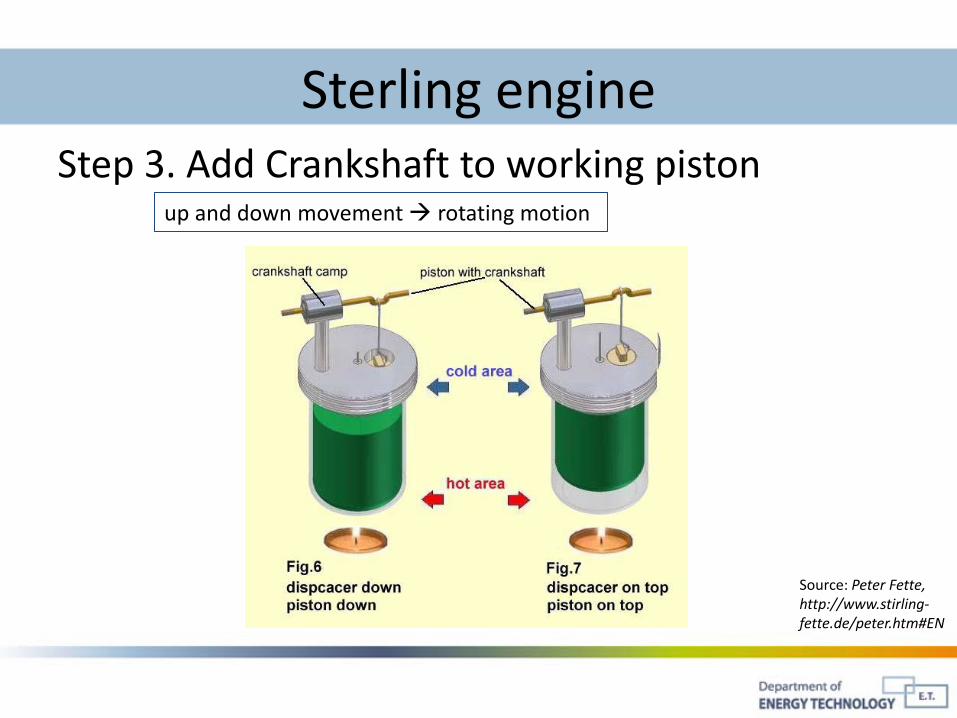
Sterling engineStep 3. Add Crankshaft to working piston
Source: Peter Fette, http://www.stirling-fette.de/peter.htm#EN
up and down movement rotating motion
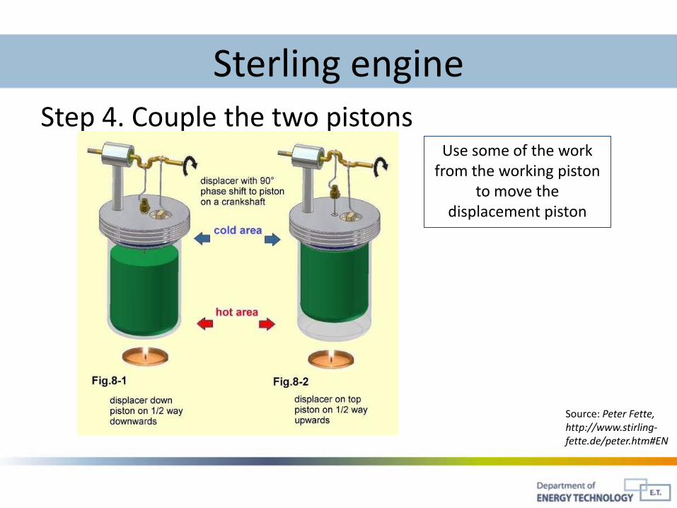
Sterling engineStep 4. Couple the two pistons
Use some of the work from the working piston
to move the displacement piston
Source: Peter Fette, http://www.stirling-fette.de/peter.htm#EN
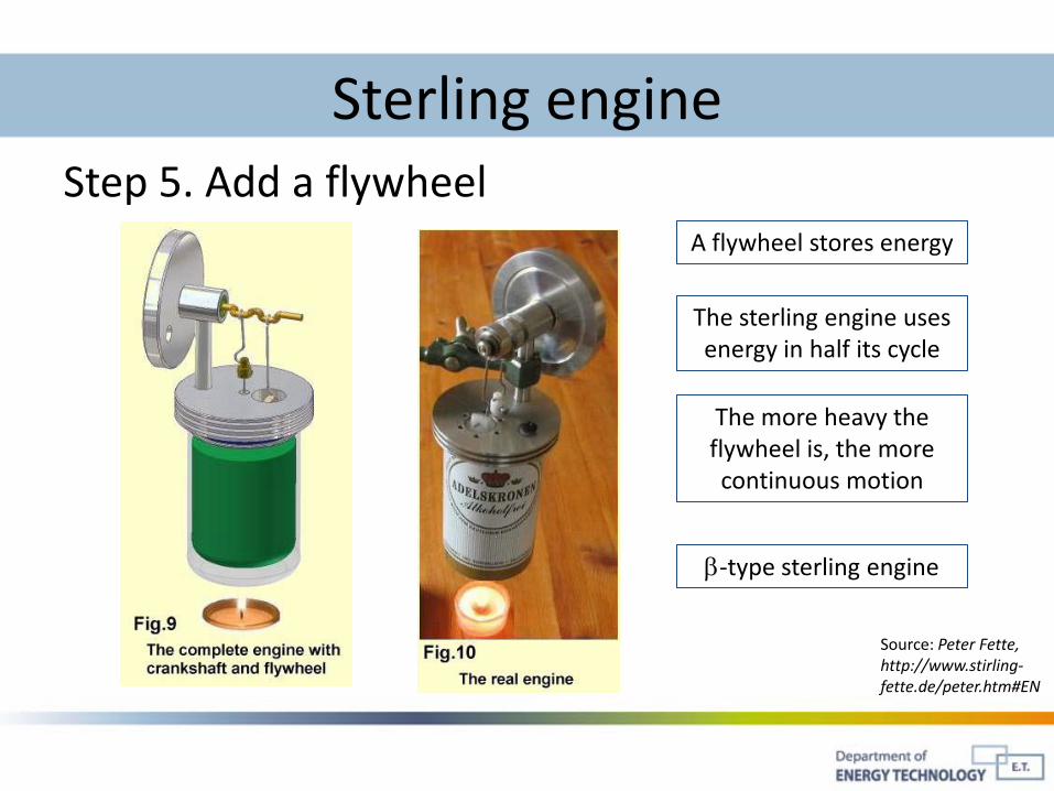
Sterling engineStep 5. Add a flywheel
A flywheel stores energy
Source: Peter Fette, http://www.stirling-fette.de/peter.htm#EN
The sterling engine uses energy in half its cycle
The more heavy the flywheel is, the more continuous motion
β-type sterling engine
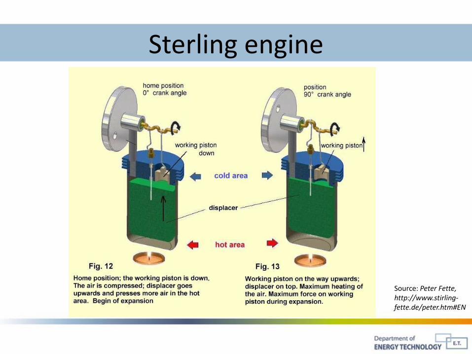
Sterling engine
Source: Peter Fette, http://www.stirling-fette.de/peter.htm#EN
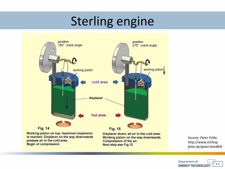
Sterling engine
Source: Peter Fette, http://www.stirling-fette.de/peter.htm#EN
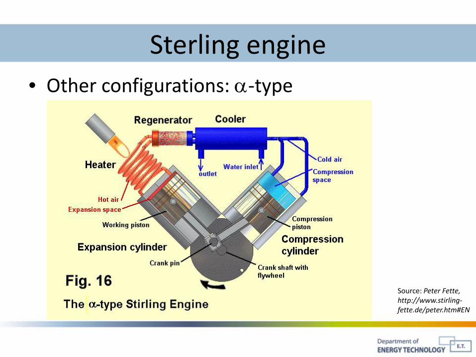
Sterling engine• Other configurations: α-type
Source: Peter Fette, http://www.stirling-fette.de/peter.htm#EN

Sterling engine• Other configurations: γ-type
Source: Peter Fette, http://www.stirling-fette.de/peter.htm#EN
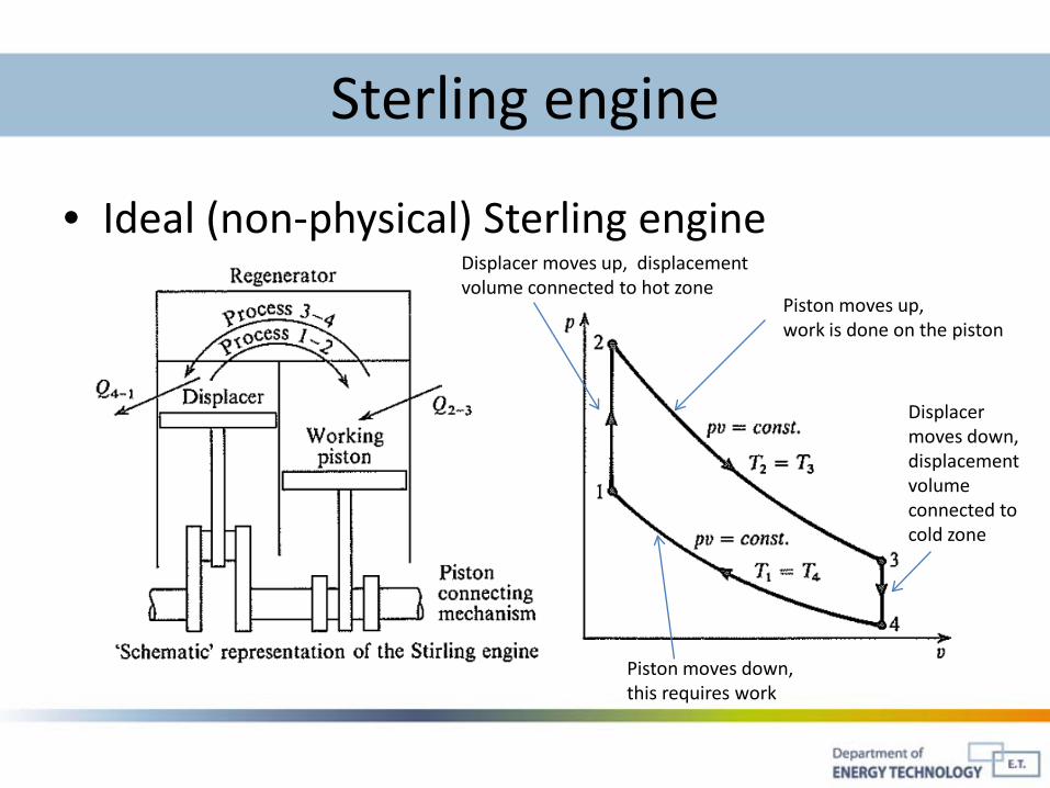
Sterling engine
• Ideal (non-physical) Sterling engine
Piston moves up, work is done on the piston
Piston moves down, this requires work
Displacer moves down, displacement volume connected to cold zone
Displacer moves up, displacement volume connected to hot zone

29
Stempelarbejde• Det udførte arbejde afhænger af procesvejen
• For en kredsproces, der løber fra tilstand 1 til tilstand 2 via procesvej B, og retur via procesvej A, er arbejdet positivt
• For den modsatte proces er arbejdet negativt
V
p
1
2
1
2
Areal under procesvej A = arbejde udført ved denne proces
Areal under procesvej B = arbejde udført ved denne proces
V
p
1
p
+ =

Sterling engine
Iso-term (or iso-thermal)
Iso-chor
Iso-term
Iso-chor
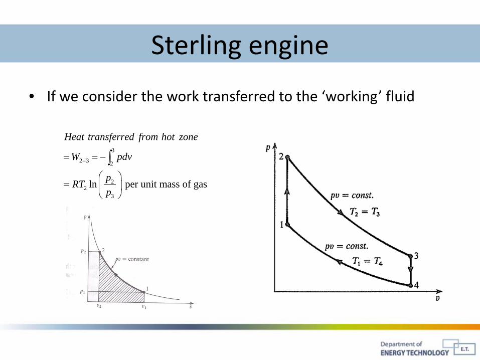
Sterling engine
• If we consider the work transferred to the ‘working’ fluid
3
2 3 2
22
3
ln per unit mass of gas
Heat transferred from hot zone
W pdv
pRTp
−= = −
=
∫

Sterling engine
• Cycle efficiency– Total work done
– Ideal efficiency
21
3 12 3
212
4
ln1 1
ln
pRTp TQ Q
TpRTp
η −
= = − = −
∑
2 12 1
3 4
ln lnp pW Q RT RTp p
= = −
∑ ∑
Sterling engine
• What reduces the efficiency for a real engine?

Sterling engine• More realistic sterling cycle
Source: Peter Fette, http://www.stirling-fette.de/peter.htm#EN

Carnot cycle
• What is the maximum possible efficiency of any engine/cycle?
• Answer: The Carnot efficiency, the efficiency of the Carnot cycle

The Carnot cycle
• Cycle efficiency can be optimized using processes that uses the least amount of work and delivers the most.
• Carnot (1820) created this theoretical engine

The Carnot cycle
• Overview
iso-thermal compression
Abiabatic compression
Iso-termal expansion
Abiabatic expansion
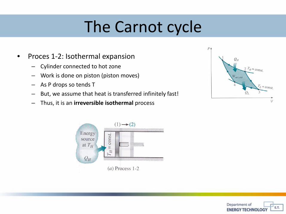
The Carnot cycle
• Proces 1-2: Isothermal expansion – Cylinder connected to hot zone
– Work is done on piston (piston moves)
– As P drops so tends T
– But, we assume that heat is transferred infinitely fast!
– Thus, it is an irreversible isothermal process

The Carnot cycle
• Proces 2-3: adiabatic expansion – The hot zone is replaced by perfect insulation
– Volume continue to expand, doing work on the piston
– Temperature drops due to the ideal gas law
– Piston moves fictionless
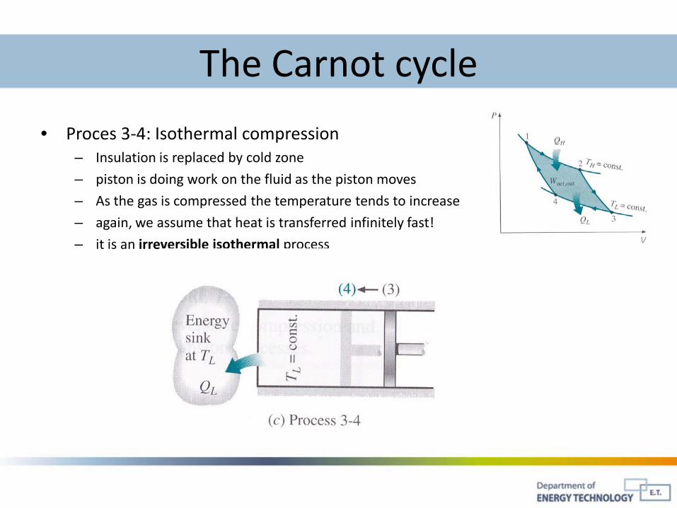
The Carnot cycle
• Proces 3-4: Isothermal compression – Insulation is replaced by cold zone
– piston is doing work on the fluid as the piston moves
– As the gas is compressed the temperature tends to increase
– again, we assume that heat is transferred infinitely fast!
– it is an irreversible isothermal process

The Carnot cycle
• Proces 4-1: adiabatic compression – The cold zone is replaced by perfect insulation
– Piston continue to compress the fluid volume
– Temperature increases due to the ideal gas law
– Piston moves fictionless
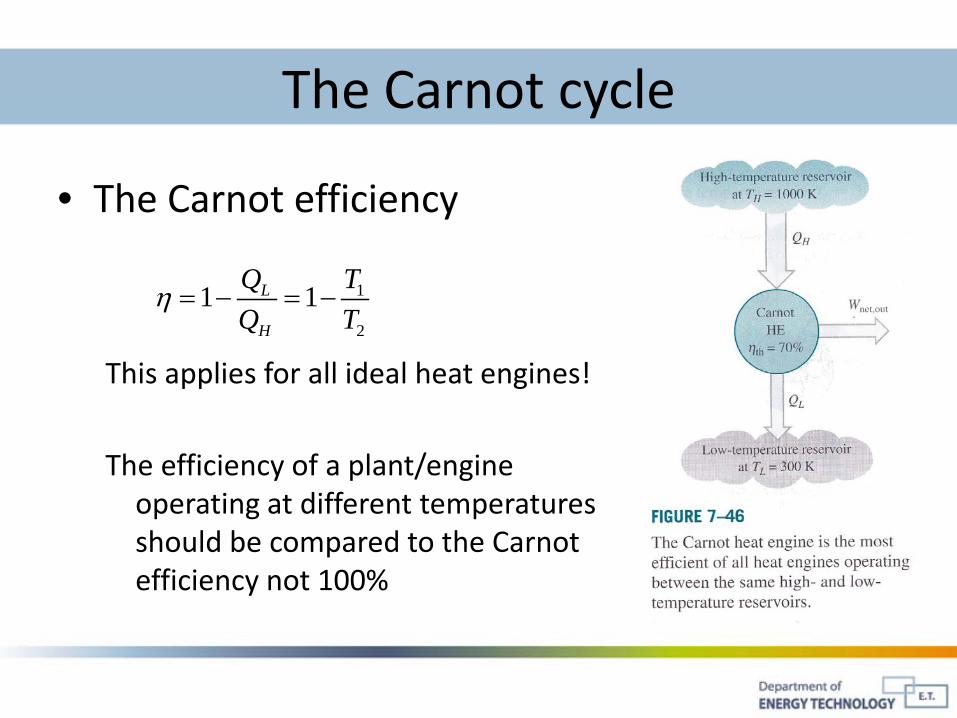
The Carnot cycle
• The Carnot efficiency
This applies for all ideal heat engines!
The efficiency of a plant/engine operating at different temperatures should be compared to the Carnot efficiency not 100%
1
2
1 1L
H
Q TQ T
η = − = −

The Carnot cycle
Source: Peter Fette, http://www.stirling-fette.de/peter.htm#EN