VPN - cisco.com · 8 Cisco ISA500 Series Integrated Security Appliances Administration Guide 333...
55
8 Cisco ISA500 Series Integrated Security Appliances Administration Guide 333 VPN This chapter describes how to configure Virtual Private Networks (VPNs) that allow other sites and remote workers to access your network resources. It includes the following sections: • About VPNs, page 334 • Viewing VPN Status, page 335 • Configuring a Site-to-Site VPN, page 340 • Configuring IPsec Remote Access, page 355 • Configuring Teleworker VPN Client, page 363 • Configuring SSL VPN, page 372 • Configuring L2TP Server, page 385 • Configuring VPN Passthrough, page 387 To access the VPN pages, click VPN in the left hand navigation pane.
Transcript of VPN - cisco.com · 8 Cisco ISA500 Series Integrated Security Appliances Administration Guide 333...
8
VPNThis chapter describes how to configure Virtual Private Networks (VPNs) that
allow other sites and remote workers to access your network resources. It
includes the following sections:
• About VPNs, page 334
• Viewing VPN Status, page 335
• Configuring a Site-to-Site VPN, page 340
• Configuring IPsec Remote Access, page 355
• Configuring Teleworker VPN Client, page 363
• Configuring SSL VPN, page 372
• Configuring L2TP Server, page 385
• Configuring VPN Passthrough, page 387
To access the VPN pages, click VPN in the left hand navigation pane.
Cisco ISA500 Series Integrated Security Appliances Administration Guide 333
VPN
About VPNs 8
About VPNs
A VPN provides a secure communication channel (also known as a “tunnel”)
between two gateway routers or between a remote PC and a gateway router. The
security appliance supports the following VPN solutions:
• Site-to-Site VPN: Connects two routers to secure traffic between two sites
that are physically separated. See Configuring a Site-to-Site VPN,
page 340.
• IPsec Remote Access: Allows the security appliance to act as a head-end
device in remote access VPNs. Your security appliance will be set as an
IPsec VPN server and push the security policies to remote VPN clients, so
that remote VPN clients have up-to-date policies in place before
establishing the VPN connections. The IPsec VPN server can also terminate
the VPN connections initiated by remote VPN clients. This flexibility allows
mobile and remote users to access critical data and applications on
corporate Intranet. See Configuring IPsec Remote Access, page 355.
• Teleworker VPN Client: Minimizes the configuration requirements at
remote locations by allowing the security appliance to work as a Cisco VPN
hardware client to receive the security policies over the VPN tunnel from a
remote IPsec VPN server. See Configuring Teleworker VPN Client,
page 363.
• SSL VPN: Allows remote users to access the corporate network by using
the Cisco AnyConnect Secure Mobility Client software. Remote access is
provided through a SSL VPN gateway. See Configuring SSL VPN,
page 372.
• L2TP: Allows remote clients to use a public IP network to secure
communicate with private corporate network servers. See Configuring
L2TP Server, page 385.
NOTE The security appliance can function as an IPsec VPN server or as a Cisco VPN
hardware client, but not both simultaneously.
Cisco ISA500 Series Integrated Security Appliances Administration Guide 334
VPN
Viewing VPN Status 8
Viewing VPN Status
This section describes how to view information for all VPN sessions. Refer to the
following topics:
• Viewing IPsec VPN Status, page 335
• Viewing SSL VPN Status, page 337
Viewing IPsec VPN Status
Use the IPsec VPN Status page to view the status of all IPsec VPN sessions. This
page is automatically updated every 10 seconds. Click Refresh to manually
refresh the data.
VPN > VPN Status > IPsec VPN Status
Field Description
Active Sessions
To manually terminate an active IPsec VPN session, click the Disconnect icon in
the Connect column. To manually terminate multiple active IPsec VPN sessions,
check them and click the Disconnect button.
If an IPsec VPN session is terminated, you can manually establish the VPN
connection by clicking the Connect icon in the Connect column.
Name VPN policy used for an IPsec VPN session.
Status Connection status for an IPsec VPN session.
VPN Type VPN connection type for an IPsec VPN session, such
as Site-to-Site, IPsec Remote Access, or Teleworker
VPN Client.
WAN Interface WAN port used for an IPsec VPN session.
Cisco ISA500 Series Integrated Security Appliances Administration Guide 335
VPN
Viewing VPN Status 8
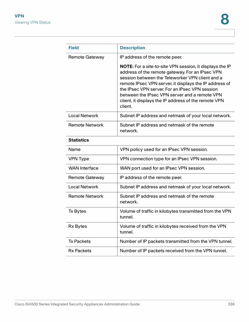
Remote Gateway IP address of the remote peer.
NOTE: For a site-to-site VPN session, it displays the IP
address of the remote gateway. For an IPsec VPN
session between the Teleworker VPN client and a
remote IPsec VPN server, it displays the IP address of
the IPsec VPN server. For an IPsec VPN session
between the IPsec VPN server and a remote VPN
client, it displays the IP address of the remote VPN
client.
Local Network Subnet IP address and netmask of your local network.
Remote Network Subnet IP address and netmask of the remote
network.
Statistics
Name VPN policy used for an IPsec VPN session.
VPN Type VPN connection type for an IPsec VPN session.
WAN Interface WAN port used for an IPsec VPN session.
Remote Gateway IP address of the remote peer.
Local Network Subnet IP address and netmask of your local network.
Remote Network Subnet IP address and netmask of the remote
network.
Tx Bytes Volume of traffic in kilobytes transmitted from the VPN
tunnel.
Rx Bytes Volume of traffic in kilobytes received from the VPN
tunnel.
Tx Packets Number of IP packets transmitted from the VPN tunnel.
Rx Packets Number of IP packets received from the VPN tunnel.
Field Description
Cisco ISA500 Series Integrated Security Appliances Administration Guide 336
VPN
Viewing VPN Status 8
Viewing SSL VPN Status
Use the SSL VPN Status page to view information for all active SSL VPN sessions.
This page is automatically updated every 10 seconds. Click Refresh to manually
refresh the data.
VPN > VPN Status > SSL VPN Status
Teleworker VPN Client
If the Teleworker VPN Client feature is enabled and the security appliance is
acting as a Cisco VPN hardware client, the following information is displayed.
Status Shows if the Teleworker VPN Client feature is enabled
or disabled.
Primary DNS IP address of the primary DNS server.
Secondary DNS IP address of the secondary DNS server.
Primary WINS IP address of the primary WINS server.
Secondary WINS IP address of the secondary WINS server.
Default Domain Default domain name.
Split Tunnel IP address and netmask for the specified split subnets.
Split DNS Domain name for the specified split DNS.
Backup Server 1/2/3 IP address or hostname for the specified backup
servers.
Field Description
Field Description
Active Sessions
To manually terminate an active SSL VPN session, click the Disconnect icon in
the Configure column. To manually terminate multiple active SSL VPN sessions,
check them and click the Disconnect button.
Session ID ID of the SSL VPN session.
User Name Name of the connected SSL VPN user.
Cisco ISA500 Series Integrated Security Appliances Administration Guide 337
VPN
Viewing VPN Status 8
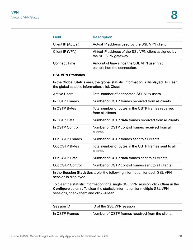
Client IP (Actual) Actual IP address used by the SSL VPN client.
Client IP (VPN) Virtual IP address of the SSL VPN client assigned by
the SSL VPN gateway.
Connect Time Amount of time since the SSL VPN user first
established the connection.
SSL VPN Statistics
In the Global Status area, the global statistic information is displayed. To clear
the global statistic information, click Clear.
Active Users Total number of connected SSL VPN users.
In CSTP Frames Number of CSTP frames received from all clients.
In CSTP Bytes Total number of bytes in the CSTP frames received
from all clients.
In CSTP Data Number of CSTP data frames received from all clients.
In CSTP Control Number of CSTP control frames received from all
clients.
Out CSTP Frames Number of CSTP frames sent to all clients.
Out CSTP Bytes Total number of bytes in the CSTP frames sent to all
clients.
Out CSTP Data Number of CSTP data frames sent to all clients.
Out CSTP Control Number of CSTP control frames sent to all clients.
In the Session Statistics table, the following information for each SSL VPN
session is displayed.
To clear the statistic information for a single SSL VPN session, click Clear in the
Configure column. To clear the statistic information for multiple SSL VPN
sessions, check them and click -Clear.
Session ID ID of the SSL VPN session.
In CSTP Frames Number of CSTP frames received from the client.
Field Description
Cisco ISA500 Series Integrated Security Appliances Administration Guide 338
VPN
Viewing VPN Status 8
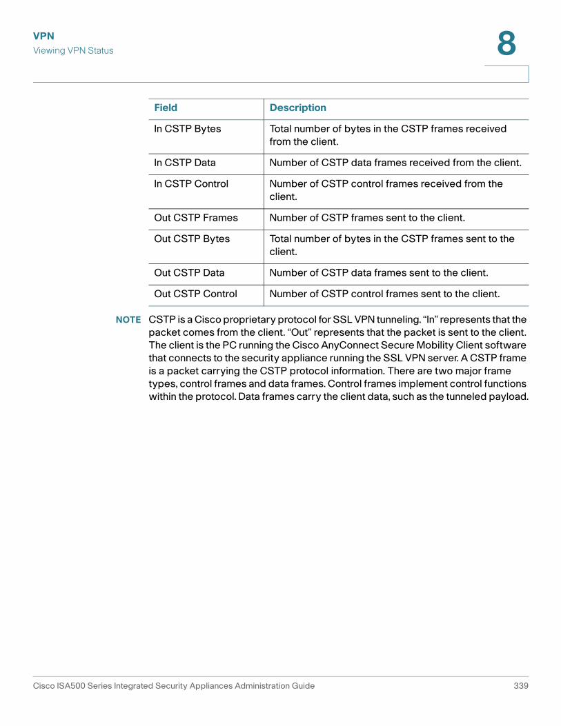
NOTE CSTP is a Cisco proprietary protocol for SSL VPN tunneling. “In” represents that the
packet comes from the client. “Out” represents that the packet is sent to the client.
The client is the PC running the Cisco AnyConnect Secure Mobility Client software
that connects to the security appliance running the SSL VPN server. A CSTP frame
is a packet carrying the CSTP protocol information. There are two major frame
types, control frames and data frames. Control frames implement control functions
within the protocol. Data frames carry the client data, such as the tunneled payload.
In CSTP Bytes Total number of bytes in the CSTP frames received
from the client.
In CSTP Data Number of CSTP data frames received from the client.
In CSTP Control Number of CSTP control frames received from the
client.
Out CSTP Frames Number of CSTP frames sent to the client.
Out CSTP Bytes Total number of bytes in the CSTP frames sent to the
client.
Out CSTP Data Number of CSTP data frames sent to the client.
Out CSTP Control Number of CSTP control frames sent to the client.
Field Description
Cisco ISA500 Series Integrated Security Appliances Administration Guide 339
VPN
Configuring a Site-to-Site VPN 8
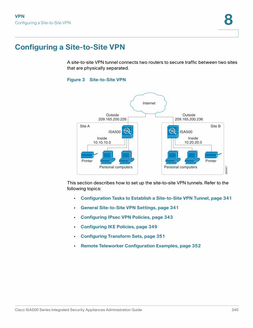
Configuring a Site-to-Site VPN
A site-to-site VPN tunnel connects two routers to secure traffic between two sites
that are physically separated.
Figure 3 Site-to-Site VPN
This section describes how to set up the site-to-site VPN tunnels. Refer to the
following topics:
• Configuration Tasks to Establish a Site-to-Site VPN Tunnel, page 341
• General Site-to-Site VPN Settings, page 341
• Configuring IPsec VPN Policies, page 343
• Configuring IKE Policies, page 349
• Configuring Transform Sets, page 351
• Remote Teleworker Configuration Examples, page 352
2830
57
Site A
ISA500 ISA500
Site B
Inside10.10.10.0
Outside209.165.200.226
Outside209.165.200.236
Inside10.20.20.0
Personal computers Personal computers
Printer Printer
Internet
Cisco ISA500 Series Integrated Security Appliances Administration Guide 340
VPN
Configuring a Site-to-Site VPN 8
Configuration Tasks to Establish a Site-to-Site VPN Tunnel
To establish a site-to-site VPN tunnel, complete the following configuration tasks:
• Add the subnet IP address objects for your local network and remote
network. See Address Management, page 175.
• (Optional) Import the certificates for authentication between two peers.
Skip this step if you want to use the pre-shared key for authentication. See
Managing Certificates for Authentication, page 418.
• Enable the site-to-site VPN feature on the security appliance. See General
Site-to-Site VPN Settings, page 341.
• Configure IKE policies. See Configuring IKE Policies, page 349.
• Configure transform policies. See Configuring Transform Sets, page 351.
• Configure IPsec VPN policies. See Configuring IPsec VPN Policies,
page 343.
• (Optional) Check an enabled IPsec VPN policy and click the Connect icon
to initiate the VPN connection.
When a site-to-site IPsec VPN policy is in place and enabled, a connection
will be triggered by any traffic that matches the policy. In this case, the VPN
tunnel will be set up automatically. However, for an IPsec VPN policy in which
this router’s Remote Network is set to Any (a “site-to-any” tunnel), a
connection cannot be set up automatically. Instead you must manually
establish the VPN connection by clicking the Connect icon.
• View the status and statistic information for all IPsec VPN sessions. See
Viewing IPsec VPN Status, page 335.
General Site-to-Site VPN Settings
STEP 1 Click VPN > Site-to-Site > IPsec Policies.
The IPsec Policies window opens. All existing IPsec VPN policies are listed in the
table. The following information is displayed:
• Name: The name of the IPsec VPN policy.
• Enable: Shows if the IPsec VPN policy is enabled or disabled.
• Status: Shows if the IPsec VPN tunnel is connected or disconnected.
Cisco ISA500 Series Integrated Security Appliances Administration Guide 341
VPN
Configuring a Site-to-Site VPN 8
• WAN Interface: The WAN port that traffic passes through over the IPsec
VPN tunnel.
• Peers: The IP address of the remote peer.
• Local: The local network of the local peer.
• Remote: The remote network of the remote peer.
• IKE: The IKE policy used for the IPsec VPN policy.
• Transform: The transform set used for the IPsec VPN policy.
STEP 2 Click On to enable site-to-site VPN, or click Off to disable it.
NOTE: Enabling the Site-to-Site VPN feature will disable the Teleworker VPN
Client feature.
STEP 3 If you enable site-to-site VPN, perform the following actions:
• To add a new IPsec VPN policy, click Add. See Configuring IPsec VPN
Policies, page 343.
• To edit an existing IPsec VPN policy, click the Edit (x) icon.
• To delete an IPsec VPN policy, click the Delete (x) icon.
• To delete multiple IPsec VPN policies, check them and click Delete.
• To enable an IPsec VPN policy, check the box in the Enable column.
• To manually establish a VPN tunnel, click the Connect icon for an enabled
IPsec VPN policy.
• To manually terminate a VPN connection, click the Disconnect icon.
• To refresh the data for site-to-site VPN, click Refresh.
STEP 4 Click Save to apply your settings.
Cisco ISA500 Series Integrated Security Appliances Administration Guide 342
VPN
Configuring a Site-to-Site VPN 8
Configuring IPsec VPN Policies
The IPsec VPN policy is used to establish the VPN connection between two
peers. ISA550 and ISA550W support up to 50 IPsec VPN tunnels. ISA570 and
ISA570W support up to 100 IPsec VPN tunnels.
NOTE Before you create an IPsec VPN policy, make sure that the IKE and transform
policies are configured. Then you can apply the IKE and transform policies to the
IPsec VPN policy.
STEP 1 Click VPN > Site-to-Site > IPsec Policies.
STEP 2 To add a new IPsec VPN policy, click Add.
Other options: To edit an entry, click the Edit (pencil) icon. To delete an entry, click
the Delete (x) icon. To delete multiple entries, check them and click Delete.
The IPsec Policies - Add/Edit window opens.
STEP 3 In the Basic Settings tab, enter the following information:
• Description: Enter the name for the IPsec VPN policy.
• IPsec Policy Enable: Click On to enable the IPsec VPN policy, or click Off to
create only the IPsec VPN policy.
• Remote Type: Specify the remote peer:
- Static IP: Choose this option if the remote peer uses a static IP address.
Enter the IP address of the remote peer in the Remote Address field.
- Dynamic IP: Choose this option if the remote peer uses a dynamic IP
address.
- FQDN (Fully Qualified Domain Name): Choose this option to use the
domain name of the remote network, such as vpn.company.com. Enter
the domain name of the remote peer in the Remote Address field.
For the example as illustrated in Figure 3, the remote site, Site B, has a public
IP address of 209.165.200.236. You should choose Static IP and enter
209.165.200.236 in the Remote Address field.
Cisco ISA500 Series Integrated Security Appliances Administration Guide 343
VPN
Configuring a Site-to-Site VPN 8
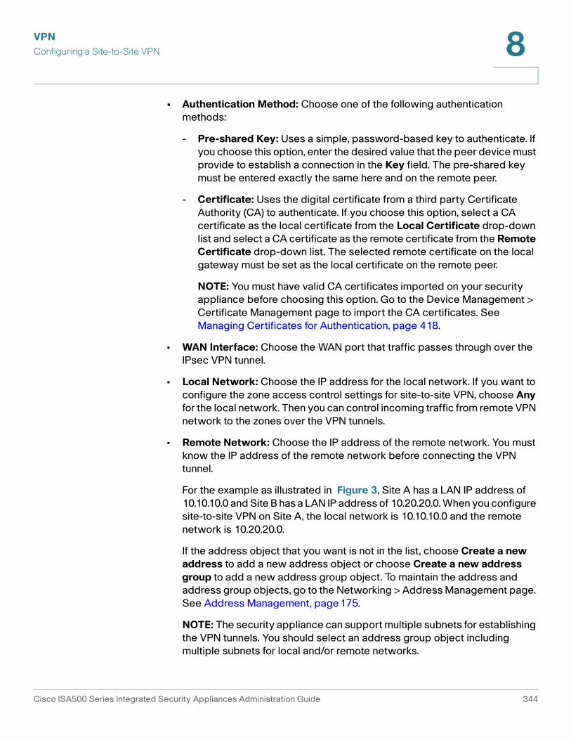
• Authentication Method: Choose one of the following authentication
methods:
- Pre-shared Key: Uses a simple, password-based key to authenticate. If
you choose this option, enter the desired value that the peer device must
provide to establish a connection in the Key field. The pre-shared key
must be entered exactly the same here and on the remote peer.
- Certificate: Uses the digital certificate from a third party Certificate
Authority (CA) to authenticate. If you choose this option, select a CA
certificate as the local certificate from the Local Certificate drop-down
list and select a CA certificate as the remote certificate from the Remote
Certificate drop-down list. The selected remote certificate on the local
gateway must be set as the local certificate on the remote peer.
NOTE: You must have valid CA certificates imported on your security
appliance before choosing this option. Go to the Device Management >
Certificate Management page to import the CA certificates. See
Managing Certificates for Authentication, page 418.
• WAN Interface: Choose the WAN port that traffic passes through over the
IPsec VPN tunnel.
• Local Network: Choose the IP address for the local network. If you want to
configure the zone access control settings for site-to-site VPN, choose Any
for the local network. Then you can control incoming traffic from remote VPN
network to the zones over the VPN tunnels.
• Remote Network: Choose the IP address of the remote network. You must
know the IP address of the remote network before connecting the VPN
tunnel.
For the example as illustrated in Figure 3, Site A has a LAN IP address of
10.10.10.0 and Site B has a LAN IP address of 10.20.20.0. When you configure
site-to-site VPN on Site A, the local network is 10.10.10.0 and the remote
network is 10.20.20.0.
If the address object that you want is not in the list, choose Create a new
address to add a new address object or choose Create a new address
group to add a new address group object. To maintain the address and
address group objects, go to the Networking > Address Management page.
See Address Management, page175.
NOTE: The security appliance can support multiple subnets for establishing
the VPN tunnels. You should select an address group object including
multiple subnets for local and/or remote networks.
Cisco ISA500 Series Integrated Security Appliances Administration Guide 344
VPN
Configuring a Site-to-Site VPN 8
STEP 4 In the Advanced Settings tab, enter the following information:
• PFS Enable: Click On to enable Perfect Forward Secrecy (PFS) to improve
security, or click Off to disable it. If you enable PFS, a Diffie-Hellman
exchange is performed for every phase-2 negotiation. PFS is desired on the
keying channel of the VPN connection.
• DPD Enable: Click On to enable Dead Peer Detection (DPD), or click Off to
disable it. DPD is a method of detecting a dead Internet Key Exchange (IKE)
peer. This method uses IPsec traffic patterns to minimize the number of
messages required to confirm the availability of a peer. DPD is used to
reclaim the lost resources in case a peer is found dead and it is also used to
perform IKE peer failover. If you enable DPD, enter the following information:
- Delay Time: Enter the value of delay time in seconds between
consecutive DPD R-U-THERE messages. DPD R-U-THERE messages are
sent only when IPsec traffic is idle. The default value is 10 seconds.
- Detection Timeout: Enter the value of detection timeout in seconds. If no
response and no traffic over the timeout, declare the peer dead. The
default value is 30 seconds.
- DPD Action: Choose one of the following actions over the detection
timeout:
Hold: Traffic from your local network to the remote network can trigger
the security appliance to re-initiate the VPN connection over the
detection timeout. We recommend that you use Hold when the remote
peer uses a static IP address.
Clean: Terminate the VPN connection over the detection timeout. You
must manually re-initiate the VPN connection. We recommend that you
use Clean when the remote peer uses dynamic IP address.
Restart: Re-initiate the VPN connection for three times over the detection
timeout.
• Windows Networking (NetBIOS) Broadcast: Click On to allow access
remote network resources by using its NetBIOS name, for example,
browsing Windows Neighborhood. NetBIOS broadcasting can resolve a
NetBIOS name to a network address. This option allows NetBIOS
broadcasts to travel over the VPN tunnel.
• Access Control: When the local network is set as Any, you can control
incoming traffic from the remote VPN network to the zones. Click Permit to
permit access, or click Deny to deny access. By default, incoming traffic
from the remote network to all zones is permitted.
Cisco ISA500 Series Integrated Security Appliances Administration Guide 345
VPN
Configuring a Site-to-Site VPN 8
NOTE: The VPN firewall rules that are automatically generated by the zone
access control settings will be added to the list of firewall rules with the
priority higher than default firewall rules, but lower than custom firewall rules.
• Apply NAT Policies: Click On to apply the NAT settings for both the local
network and the remote network communicating over the VPN tunnel. This
option is particularly useful in cases where both sides of a tunnel use either
the same or overlapping subnets.
- Translates Local Network: To translate the local network, select a
translated address object for the local network.
- Translates Remote Network: To translate the remote network, select a
translated address object for the remote network.
If the address object that you want is not in the list, choose Create a new
address to add a new address object or choose Create a new address
group to add a new address group object. To maintain the address or
address group objects, go to the Networking > Address Management page.
See Address Management, page175.
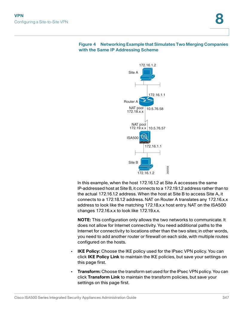
Figure 4 shows a networking example that simulates two merging
companies with the same IP addressing scheme. Two routers are connected
with a VPN tunnel, and the networks behind each router are the same. For
one site to access the hosts at the other site, Network Address Translation
(NAT) is used on the routers to change both the source and destination
addresses to different subnets.
Cisco ISA500 Series Integrated Security Appliances Administration Guide 346
VPN
Configuring a Site-to-Site VPN 8
Figure 4 Networking Example that Simulates Two Merging Companies
with the Same IP Addressing Scheme
In this example, when the host 172.16.1.2 at Site A accesses the same
IP-addressed host at Site B, it connects to a 172.19.1.2 address rather than to
the actual 172.16.1.2 address. When the host at Site B to access Site A, it
connects to a 172.18.1.2 address. NAT on Router A translates any 172.16.x.x
address to look like the matching 172.18.x.x host entry. NAT on the ISA500
changes 172.16.x.x to look like 172.19.x.x.
NOTE: This configuration only allows the two networks to communicate. It
does not allow for Internet connectivity. You need additional paths to the
Internet for connectivity to locations other than the two sites; in other words,
you need to add another router or firewall on each side, with multiple routes
configured on the hosts.
• IKE Policy: Choose the IKE policy used for the IPsec VPN policy. You can
click IKE Policy Link to maintain the IKE policies, but save your settings on
this page first.
• Transform: Choose the transform set used for the IPsec VPN policy. You can
click Transform Link to maintain the transform policies, but save your
settings on this page first.
2830
58
172.16.1.2
172.16.1.2
Site A
Site B
Router A
ISA500
172.16.1.1
172.16.1.1
10.5.76.58
10.5.76.57
NAT pool172.18.x.x
NAT pool172.19.x.x
Cisco ISA500 Series Integrated Security Appliances Administration Guide 347
VPN
Configuring a Site-to-Site VPN 8
• SA-Lifetime: Enter the lifetime of the IPsec Security Association (SA). The
IPsec SA lifetime represents the interval after which the IPsec SA becomes
invalid. The IPsec SA is renegotiated after this interval. The default value is 1
hour.
STEP 5 In the VPN Failover tab, enter the following information:
• WAN Failover Enable: Click On to enable WAN Failover for site-to-site VPN,
or click Off to disable it. If you enable WAN Failover, the backup WAN port
ensures that VPN traffic rolls over to the backup link whenever the primary
link fails. The security appliance will automatically update the local WAN
gateway for the VPN tunnel based on the configurations of the backup WAN
link. For this purpose, Dynamic DNS has to be configured because the IP
address will change due to failover, or let the remote gateway use dynamic
IP address.
NOTE: To enable WAN Failover for site-to-site VPN, make sure that the
secondary WAN port was configured and the WAN redundancy was set as
the Failover or Load Balancing mode.
• Redundant Gateway: Click On to enable Redundant Gateway, or click Off to
disable it. If you enable Redundant Gateway, when the connection of the
remote gateway fails, the backup connection automatically becomes active.
A backup policy comes into effect only if the primary policy fails.
- Select Backup Policy: Choose a policy to act as a backup of this policy.
- Fallback Time to switch from back-up to primary: Enter the number of
seconds that must pass to confirm that the primary tunnel has recovered
from a failure. If the primary tunnel is up for the specified time, the
security appliance will switch to the primary tunnel by disabling the
backup tunnel. Enter a value in the range 3 to 59 seconds. The default
value is 5 seconds.
NOTE: DPD should be enabled if you want to use the Redundant
Gateway feature for IPsec VPN connection.
STEP 6 Click OK to save your settings.
STEP 7 When both the Site-to-Site VPN feature and the IPsec VPN policy are enabled, a
warning message appears saying “Do you want to make this connection active
when the settings are saved?”
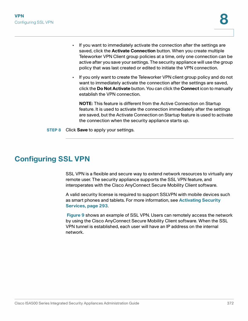
• If you want to immediately activate the connection after the settings are
saved, click the Activate Connection button. After you save your settings,
the security appliance will immediately try to initiate the VPN connection.
You can check the Status column to view its connection status.
Cisco ISA500 Series Integrated Security Appliances Administration Guide 348
VPN
Configuring a Site-to-Site VPN 8
• If you only want to create the IPsec VPN policy and do not want to
immediately activate the connection after the settings are saved, click the
Do Not Activate button. The connection will be triggered by any traffic that
matches the IPsec VPN policy and the VPN tunnel will be set up
automatically. You can also click the Connect icon to manually establish the
VPN connection.
STEP 8 Click Save to apply your settings.
Configuring IKE Policies
The Internet Key Exchange (IKE) protocol is a negotiation protocol that includes an
encryption method to protect data and ensure privacy. It is also an authentication
method to verify the identity of devices that are trying to connect to your network.
You can create IKE policies to define the security parameters (such as
authentication of the peer, encryption algorithms, and so forth) to be used for a
VPN tunnel.
NOTE Up to 16 IKE policies can be configured on the security appliance.
STEP 1 Click VPN > Site-to-Site > IKE Policies.
The IKE Policies window opens. The default and custom IKE policies are listed in
the table.
STEP 2 To add a new IKE policy, click Add.
Other options: To edit an entry, click the Edit (pencil) icon. To delete an entry, click
the Delete (x) icon. To delete multiple entries, check them and click Delete. The
default IKE policy (DefaultIke) cannot be edited or deleted.
The IKE Policy - Add/Edit window opens.
STEP 3 Enter the following information:
• Name: Enter the name for the IKE policy.
• Encryption: Choose the algorithm used to negotiate the security
association. There are four algorithms supported by the security appliance:
ESP_3DES, ESP_AES_128, ESP_AES_192, and ESP_AES_256.
• Hash: Specify the authentication algorithm for the VPN header. There are
two hash algorithms supported by the security appliance: SHA1 and MD5.
Cisco ISA500 Series Integrated Security Appliances Administration Guide 349
VPN
Configuring a Site-to-Site VPN 8
NOTE: Ensure that the authentication algorithm is configured identically on
both sides.
• Authentication: Specify the authentication method that the security
appliance uses to establish the identity of each IPsec peer.
- Pre-shared Key: Uses a simple, password-based key to authenticate.
The alpha-numeric key is shared with the IKE peer. Pre-shared keys do
not scale well with a growing network but are easier to set up in a small
network.
- RSA_SIG: Uses a digital certificate to authenticate. RSA_SIG is a digital
certificate with keys generated by the RSA signatures algorithm. In this
case, a certificate must be configured in order for the RSA-Signature to
work.
• D-H Group: Choose the Diffie-Hellman group identifier, which the two IPsec
peers use to derive a shared secret without transmitting it to each other. The
D-H Group sets the strength of the algorithm in bits. The lower the
Diffie-Hellman group number, the less CPU time it requires to be executed.
The higher the Diffie-Hellman group number, the greater the security.
- Group 2 (1024-bit)
- Group 5 (1536-bit)
- Group 14 (2048-bit)
• Lifetime: Enter the number of seconds for the IKE Security Association (SA)
to remain valid. As a general rule, a shorter lifetime provides more secure
ISAKMP (Internet Security Association and Key Management Protocol)
negotiations (up to a point). However, with shorter lifetimes, the security
appliance sets up future IPsec SAs more quickly. The default value is 24
hours.
STEP 4 Click OK to save your settings.
STEP 5 Click Save to apply your settings.
Cisco ISA500 Series Integrated Security Appliances Administration Guide 350
VPN
Configuring a Site-to-Site VPN 8
Configuring Transform Sets
A transform set specifies the algorithms of integrity and encryption that the peer
will use to protect data communications. Two peers must use the same algorithm
to communicate.
NOTE Up to 16 transform sets can be configured on the security appliance.
STEP 1 Click VPN > Site-to-Site > Transform Policies.
The Transform Sets window opens. The default and custom transform sets are
listed in the table.
STEP 2 To add a new transform set, click Add.
Other options: To edit an entry, click the Edit (pencil) icon. To delete an entry, click
the Delete (x) icon. To delete multiple entries, check them and click Delete. The
default transform set (DefaultTrans) cannot be edited or deleted.
The Transform Set - Add/Edit window opens.
STEP 3 Enter the following information:
• Name: Enter the name for the transform set.
• Integrity: Choose the HASH algorithm used to ensure the data integrity. It
ensures that a packet comes from where it says it comes from, and that it has
not been modified in transit.
- ESP_SHA1_HMAC: Authentication with SHA1 (160-bit).
- ESP_MD5_HMAC: Authentication with MD5 (128-bit). MD5 has a smaller
digest and is considered to be slightly faster than SHA1. A successful (but
extremely difficult) attack against MD5 has occurred; however, the HMAC
variant that IKE uses prevents this attack.
• Encryption: Choose the symmetric encryption algorithm that protects data
transmission between two IPsec peers. The default is ESP_3DES. The
Advanced Encryption Standard supports key lengths of 128, 192, 256 bits.
- ESP_3DES: Encryption with 3DES (168-bit).
- ESP_AES_128: Encryption with AES (128-bit).
- ESP_AES_192: Encryption with AES (192-bit).
- ESP_AES_256: Encryption with AES (256-bit).
STEP 4 Click OK to save your settings.
Cisco ISA500 Series Integrated Security Appliances Administration Guide 351
VPN
Configuring a Site-to-Site VPN 8
STEP 5 Click Save to apply your settings.
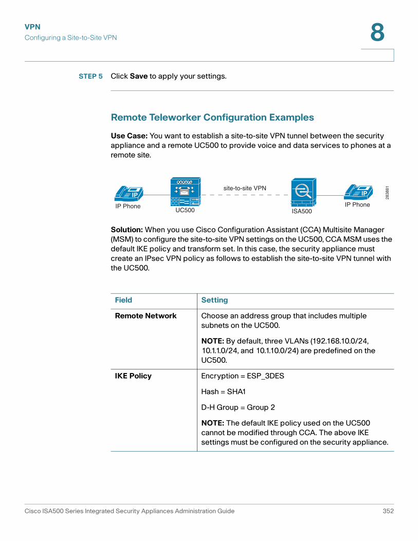
Remote Teleworker Configuration Examples
Use Case: You want to establish a site-to-site VPN tunnel between the security
appliance and a remote UC500 to provide voice and data services to phones at a
remote site.
Solution: When you use Cisco Configuration Assistant (CCA) Multisite Manager
(MSM) to configure the site-to-site VPN settings on the UC500, CCA MSM uses the
default IKE policy and transform set. In this case, the security appliance must
create an IPsec VPN policy as follows to establish the site-to-site VPN tunnel with
the UC500.
ISA500IP Phone
IP
UC500IP Phone
IPsite-to-site VPN
2838
81
Field Setting
Remote Network Choose an address group that includes multiple
subnets on the UC500.
NOTE: By default, three VLANs (192.168.10.0/24,
10.1.1.0/24, and 10.1.10.0/24) are predefined on the
UC500.
IKE Policy Encryption = ESP_3DES
Hash = SHA1
D-H Group = Group 2
NOTE: The default IKE policy used on the UC500
cannot be modified through CCA. The above IKE
settings must be configured on the security appliance.
Cisco ISA500 Series Integrated Security Appliances Administration Guide 352
VPN
Configuring a Site-to-Site VPN 8
Use Case: The UC500 device is behind the security appliance. You want to
establish a site-to-site VPN tunnel between two security appliances to provide
voice and data services to phones at a remote site.
Solution: When you configure the site-to-site VPN on the security appliances,
make sure that the local network on the security appliance at Site A is set as “Any”
and the remote network on the security appliance at Site B is set as “Any”.
Because the security appliance provides the firewall, Network Address
Translation (NAT), and SIP Application Level Gateway (SIP ALG) for your network,
you must disable those functions on the UC500. For instructions, refer to the
documentation or online Help for the Cisco Configuration Assistant (CCA).
To allow the hosts in non-native subnets of the security appliance to access the
Internet over the VPN tunnels, you must manually create advanced NAT rules on
your security appliance. Go to the Firewall > NAT > Advanced NAT page to do this.
For example, you can create an advanced NAT rule as follows to allow the hosts in
the data LAN (10.25.1.0/24) behind the UC500 to access the Internet:
Transform Integrity = ESP_SHA1_HMAC
Encryption = ESP_3DES
NOTE: The default transform set used on the UC500
cannot be modified through CCA. The above transform
settings must be configured on the security appliance.
Field Setting
ISA500IP Phone
IP
UC500IP Phone
IPsite-to-site VPN
ISA500
Site A Site B
2838
82
Name datalan-behinduc500
Enable On
From Any
To WAN1
Cisco ISA500 Series Integrated Security Appliances Administration Guide 353
VPN
Configuring a Site-to-Site VPN 8
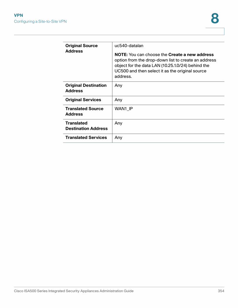
Original Source
Address
uc540-datalan
NOTE: You can choose the Create a new address
option from the drop-down list to create an address
object for the data LAN (10.25.1.0/24) behind the
UC500 and then select it as the original source
address.
Original Destination
Address
Any
Original Services Any
Translated Source
Address
WAN1_IP
Translated
Destination Address
Any
Translated Services Any
Cisco ISA500 Series Integrated Security Appliances Administration Guide 354
VPN
Configuring IPsec Remote Access 8
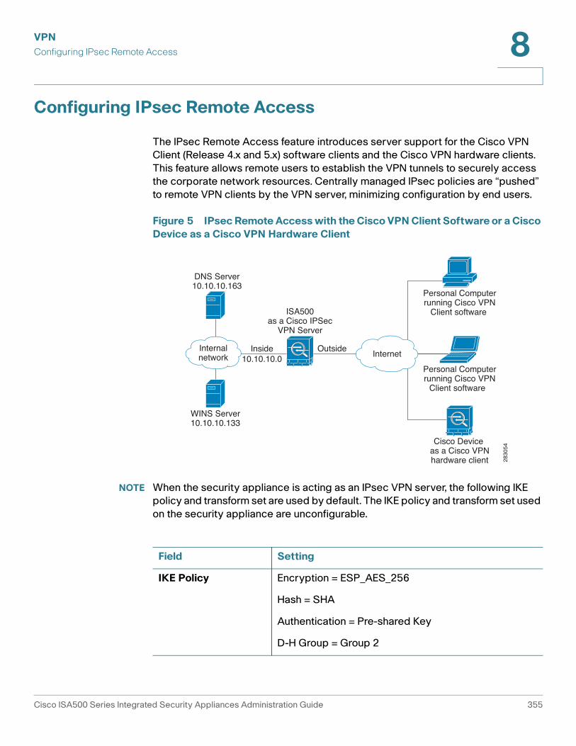
Configuring IPsec Remote Access
The IPsec Remote Access feature introduces server support for the Cisco VPN
Client (Release 4.x and 5.x) software clients and the Cisco VPN hardware clients.
This feature allows remote users to establish the VPN tunnels to securely access
the corporate network resources. Centrally managed IPsec policies are “pushed”
to remote VPN clients by the VPN server, minimizing configuration by end users.
Figure 5 IPsec Remote Access with the Cisco VPN Client Software or a Cisco
Device as a Cisco VPN Hardware Client
NOTE When the security appliance is acting as an IPsec VPN server, the following IKE
policy and transform set are used by default. The IKE policy and transform set used
on the security appliance are unconfigurable. 28
3054
Inside10.10.10.0
Outside
DNS Server10.10.10.163
WINS Server10.10.10.133
Internalnetwork
ISA500as a Cisco IPSec
VPN Server
Cisco Device as a Cisco VPNhardware client
Personal Computerrunning Cisco VPN
Client software
Personal Computerrunning Cisco VPN
Client software
Internet
Field Setting
IKE Policy Encryption = ESP_AES_256
Hash = SHA
Authentication = Pre-shared Key
D-H Group = Group 2
Cisco ISA500 Series Integrated Security Appliances Administration Guide 355
VPN
Configuring IPsec Remote Access 8
This section describes how to configure the IPsec Remote Access feature. Refer
to the following topics:
• Cisco VPN Client Compatibility, page 356
• Enabling IPsec Remote Access, page 357
• Configuring IPsec Remote Access Group Policies, page 357
• Allowing IPsec Remote VPN Clients to Access the Internet, page 360
Cisco VPN Client Compatibility
The remote VPN client can be a Cisco device acting as a Cisco VPN hardware
client or a PC running the Cisco VPN Client software (Release 4.x or 5.x).
The Cisco VPN Client software is an IPsec client software for Windows, Mac, or
Linux users. The Cisco VPN Client software is compatible with the following
platforms:
• Windows 7 (32-bit and 64-bit)
• Windows Vista (32-bit and 64-bit)
• Windows XP (32-bit)
• Linux Intel (2.6.x kernel)
• Mac OS X 10.5 and 10.6
You can find the software installers for Cisco VPN Client from the CD that is
packed with the device. The CD includes the VPN client packages for Windows,
Mac OS X, and Linux. Choose correct VPN client package from the CD to
download depending on your operating system.
You can also download the Cisco VPN Client software by using this link:
http://www.cisco.com/cisco/software/navigator.html?mdfid=278875403
Then choose Cisco VPN Client.
Transform Integrity = SHA
Encryption = ESP_AES_256
Field Setting
Cisco ISA500 Series Integrated Security Appliances Administration Guide 356
VPN
Configuring IPsec Remote Access 8
NOTE You must log in and possess a valid service contract in order to access the Cisco
VPN Client software. A 3-year Cisco Small Business Support Service Contract
(CON-SBS-SVC2) is required to download the client software from Cisco.com. If
you don’t have one, contact your partner or reseller, or Cisco Support for more
information.
For more information about how to download, install, and configure the Cisco VPN
Client software, see this web page:
http://www.cisco.com/en/US/products/sw/secursw/ps2308/index.html
Enabling IPsec Remote Access
STEP 1 Click VPN > IPsec Remote Access.
STEP 2 Click On to enable the IPsec Remote Access feature and hence set the security
appliance as an IPsec VPN server, or click Off to disable it.
NOTE: Enabling the IPsec Remote Access feature will disable the Teleworker VPN
Client feature.
STEP 3 Click Save to apply your settings.
Configuring IPsec Remote Access Group Policies
An IPsec Remote Access group policy is used by remote VPN clients to establish
the VPN connections.
NOTE Up to 16 IPsec Remote Access group policies can be configured on the security
appliance.
STEP 1 Click VPN > IPsec Remote Access.
STEP 2 To add an IPsec Remote Access group policy, click Add.
Other Options: To edit an entry, click the Edit (pencil) icon. To delete an entry, click
the Delete (x) icon. To delete multiple entries, check them and click Delete.
The IPsec Remote Access - Add/Edit window opens.
STEP 3 In the Basic Settings tab, enter the following information:
• Group Name: Enter the name for the group policy.
Cisco ISA500 Series Integrated Security Appliances Administration Guide 357
VPN
Configuring IPsec Remote Access 8
• WAN Interface: Choose the WAN port that traffic passes through over the
VPN tunnel.
• IKE Authentication Method: Choose the authentication method.
- Pre-shared Key: Uses a simple, password-based key to authenticate. If
you choose this option, enter the desired value that remote VPN clients
must provide to establish the VPN connections in the Password field. The
pre-shared key must be entered exactly the same here and on the remote
clients.
- Certificate: Uses the digital certificate from a third party Certificate
Authority (CA) to authenticate. If you choose this option, select a CA
certificate as the local certificate from the Local Certificate drop-down
list and select a CA certificate as the remote certificate from the Peer
Certificate drop-down list for authentication. The selected remote
certificate on the IPsec VPN server must be set as the local certificate on
remote VPN clients.
NOTE: You must have valid CA certificates imported on your security
appliance before choosing this option. Go to the Device Management >
Certificate Management page to import the CA certificates. See
Managing Certificates for Authentication, page 418.
• Mode: The Cisco VPN hardware client supports NEM (Network Extension
Mode) and Client mode. The IPsec Remote Access group policy must be
configured with the corresponding mode to allow only the Cisco VPN
hardware clients in the same operation mode to be connected. For example,
if you choose the Client mode for the group policy, only the Cisco VPN
hardware clients in Client mode can be connected by using this group policy.
For more information about the operation mode, see Modes of Operation,
page 365.
- Choose Client for the group policy that is used for both the PC running
the Cisco VPN Client software and the Cisco device acting as a Cisco
VPN hardware client in Client mode. In Client mode, the IPsec VPN server
can assign the IP addresses to the outside interfaces of remote VPN
clients. To define the pool range for remote VPN clients, enter the starting
and ending IP addresses in the Start IP and End IP fields.
- Choose NEM for the group policy that is only used for the Cisco device
acting as a Cisco VPN hardware client in NEM mode.
Cisco ISA500 Series Integrated Security Appliances Administration Guide 358
VPN
Configuring IPsec Remote Access 8
• Client Internet Access: Check this box to automatically create advanced
NAT rules to allow remote VPN clients to access the Internet over the VPN
tunnels. If you uncheck this box, you can manually create advanced NAT
rules. See Allowing IPsec Remote VPN Clients to Access the Internet,
page 360.
• WAN Failover: Click On to enable WAN Failover, or click Off to disable it. If
you enable WAN Failover, traffic is automatically redirected to the secondary
link when the primary link is down.
NOTE: To enable WAN Failover for IPsec Remote Access, make sure that the
secondary WAN port was configured and the WAN redundancy was set as
the Load Balancing or Failover mode.
NOTE: The security appliance will automatically update the local WAN
gateway for the VPN tunnel based on the configurations of the backup WAN
link. For this purpose, Dynamic DNS has to be configured because the IP
address will change due to failover and remote VPN clients must use the
domain name of the IPsec VPN server to establish the VPN connections.
STEP 4 In the Zone Access Control tab, you can control access from the PC running the
Cisco VPN Client software or the private network of the Cisco VPN hardware
client to the zones over the VPN tunnels. Click Permit to permit access, or click
Deny to deny access.
NOTE: The VPN firewall rules that are automatically generated by the zone access
control settings will be added to the list of firewall rules with the priority higher
than the default firewall rules, but lower than the custom firewall rules.
STEP 5 In the Mode Configuration Settings tab, enter the following information:
• Primary DNS Server: Enter the IP address of the primary DNS server.
• Secondary DNS Server: Enter the IP address of the secondary DNS server.
• Primary WINS Server: Enter the IP address of the primary WINS server.
• Secondary WINS Server: Enter the IP address of the secondary WINS
server.
• Default Domain: Enter the default domain name that should be pushed to
remote VPN clients.
• Backup Server 1/2/3: Enter the IP address or hostname for the backup
server. You can specify up to three IPsec VPN servers as backup. When the
connection to the primary server fails, the VPN clients can attempt to
connect to the backup servers. The backup server 1 has the highest priority
and the backup server 3 has the lowest priority.
Cisco ISA500 Series Integrated Security Appliances Administration Guide 359
VPN
Configuring IPsec Remote Access 8
NOTE: The backup servers that you specified on the IPsec VPN server will
be sent to remote VPN clients when initiating the VPN connections. The
remote VPN clients will cache them.
• Split Tunnel: Click On to enable the split tunneling feature, or click Off to
disable it. Split tunneling allows only traffic that is specified by the VPN client
routes to corporate resources through the VPN tunnel. If you enable split
tunneling, you need to define the split subnets. To add a subnet, enter the IP
address and netmask in the Protected Network and Netmask fields and
click Add. To delete a subnet, select it from the list and click Delete.
• Split DNS: Split DNS directs DNS packets in clear text through the VPN
tunnel to domains served by the corporate DNS. To add a domain, enter the
Domain name that should be resolved by your network’s DNS server, and
then click Add. To delete a domain, select it from the list and click Delete.
NOTE: To use Split DNS, you must also enable the split tunneling feature and
specify the domains. The Split DNS feature supports up to 10 domains.
STEP 6 Click OK to save your settings.
STEP 7 Click Save to apply your settings.
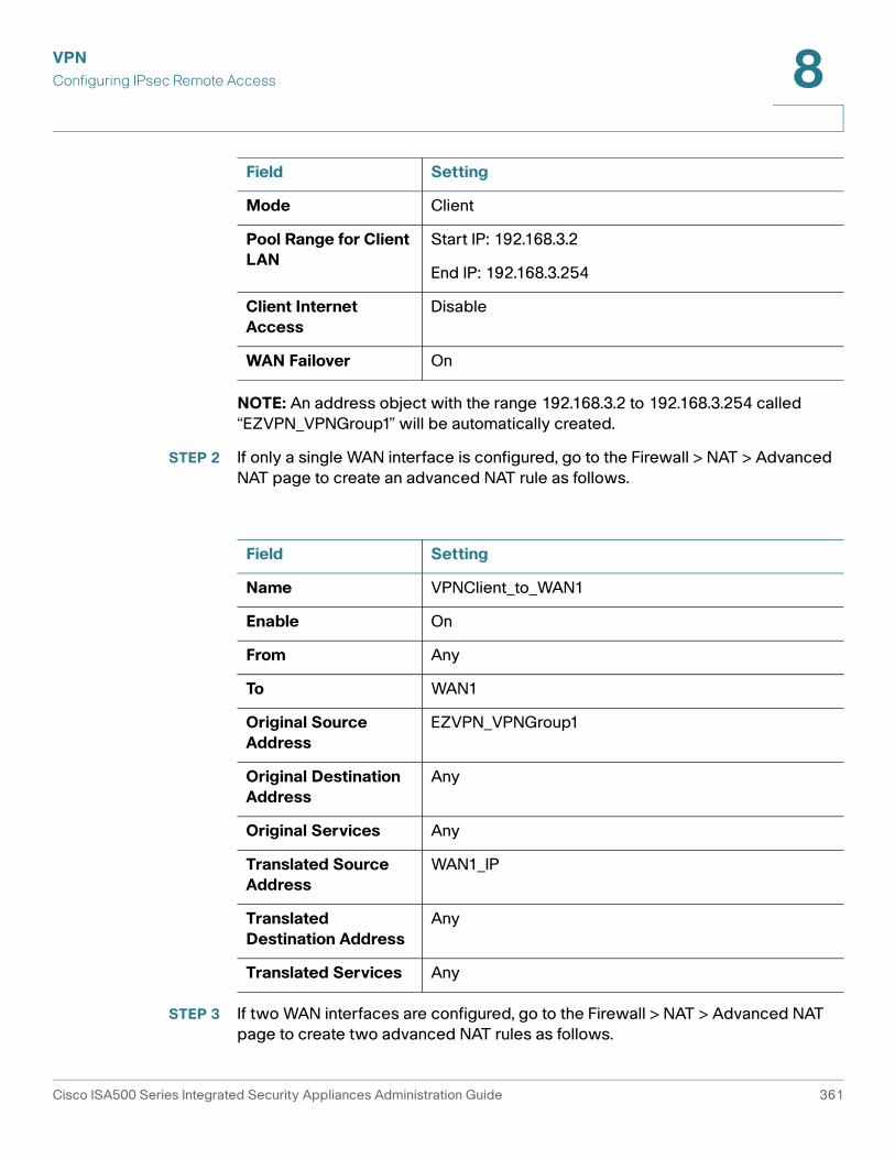
Allowing IPsec Remote VPN Clients to Access the Internet
Enabling Client Internet Access will automatically create advanced NAT rules to
allow remote VPN clients to access the Internet over the VPN tunnels. This section
provides an example on manually configuring advanced NAT rules to allow remote
VPN clients to access the Internet over the VPN tunnels.
STEP 1 Assuming that you enable the IPsec Remote Access feature and create a group
policy as follows:
Field Setting
Group Name VPNGroup1
WAN Interface WAN1
IKE Authentication
Method
Pre-shared key
Cisco ISA500 Series Integrated Security Appliances Administration Guide 360
VPN
Configuring IPsec Remote Access 8
NOTE: An address object with the range 192.168.3.2 to 192.168.3.254 called
“EZVPN_VPNGroup1” will be automatically created.
STEP 2 If only a single WAN interface is configured, go to the Firewall > NAT > Advanced
NAT page to create an advanced NAT rule as follows.
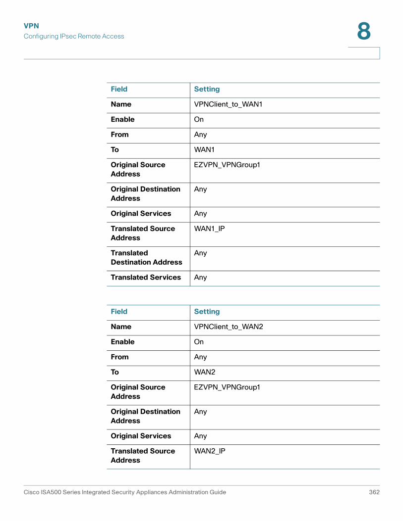
STEP 3 If two WAN interfaces are configured, go to the Firewall > NAT > Advanced NAT
page to create two advanced NAT rules as follows.
Mode Client
Pool Range for Client
LAN
Start IP: 192.168.3.2
End IP: 192.168.3.254
Client Internet
Access
Disable
WAN Failover On
Field Setting
Field Setting
Name VPNClient_to_WAN1
Enable On
From Any
To WAN1
Original Source
Address
EZVPN_VPNGroup1
Original Destination
Address
Any
Original Services Any
Translated Source
Address
WAN1_IP
Translated
Destination Address
Any
Translated Services Any
Cisco ISA500 Series Integrated Security Appliances Administration Guide 361
VPN
Configuring IPsec Remote Access 8
Field Setting
Name VPNClient_to_WAN1
Enable On
From Any
To WAN1
Original Source
Address
EZVPN_VPNGroup1
Original Destination
Address
Any
Original Services Any
Translated Source
Address
WAN1_IP
Translated
Destination Address
Any
Translated Services Any
Field Setting
Name VPNClient_to_WAN2
Enable On
From Any
To WAN2
Original Source
Address
EZVPN_VPNGroup1
Original Destination
Address
Any
Original Services Any
Translated Source
Address
WAN2_IP
Cisco ISA500 Series Integrated Security Appliances Administration Guide 362
VPN
Configuring Teleworker VPN Client 8
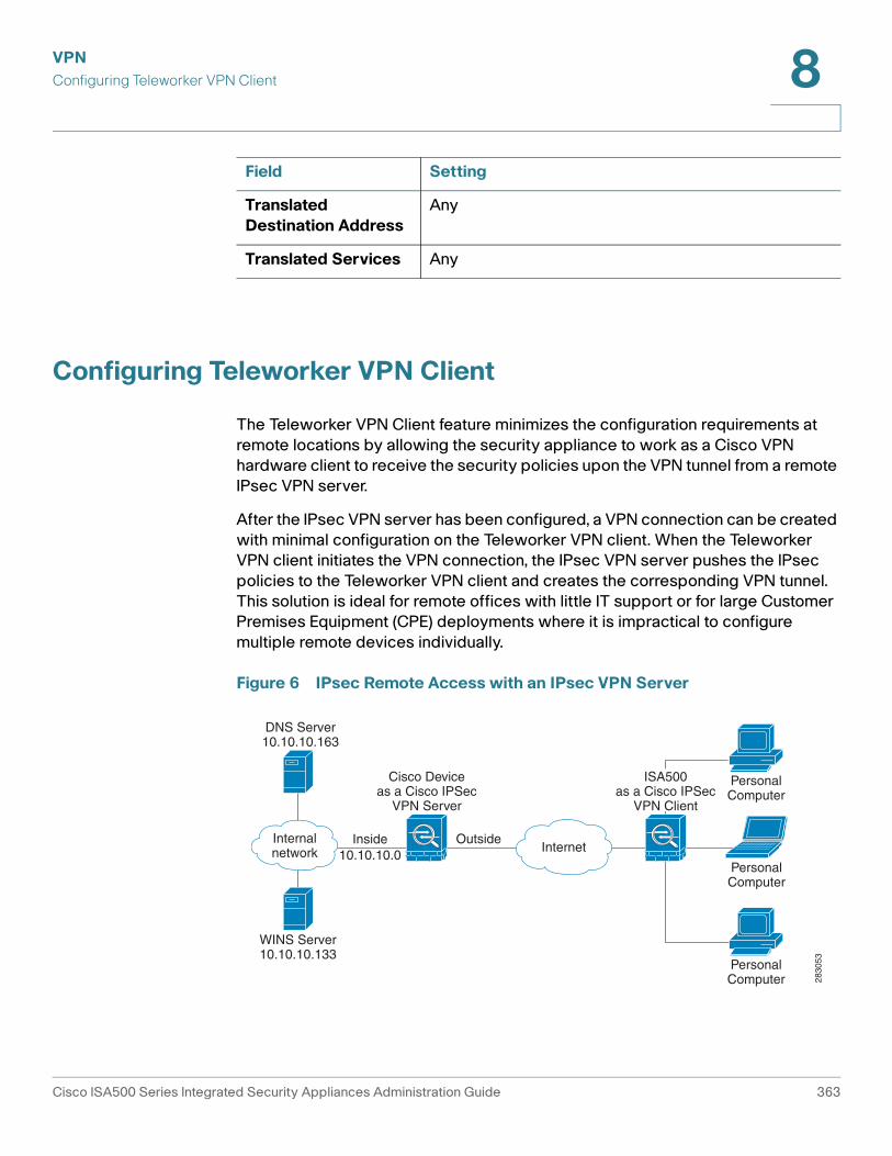
Configuring Teleworker VPN Client
The Teleworker VPN Client feature minimizes the configuration requirements at
remote locations by allowing the security appliance to work as a Cisco VPN
hardware client to receive the security policies upon the VPN tunnel from a remote
IPsec VPN server.
After the IPsec VPN server has been configured, a VPN connection can be created
with minimal configuration on the Teleworker VPN client. When the Teleworker
VPN client initiates the VPN connection, the IPsec VPN server pushes the IPsec
policies to the Teleworker VPN client and creates the corresponding VPN tunnel.
This solution is ideal for remote offices with little IT support or for large Customer
Premises Equipment (CPE) deployments where it is impractical to configure
multiple remote devices individually.
Figure 6 IPsec Remote Access with an IPsec VPN Server
Translated
Destination Address
Any
Translated Services Any
Field Setting
Inside10.10.10.0
Outside
DNS Server10.10.10.163
WINS Server10.10.10.133
InternetInternalnetwork
Cisco Deviceas a Cisco IPSec
VPN Server
ISA500as a Cisco IPSec
VPN Client
PersonalComputer
PersonalComputer
PersonalComputer 28
3053
Cisco ISA500 Series Integrated Security Appliances Administration Guide 363
VPN
Configuring Teleworker VPN Client 8
NOTE When the security appliance is acting as a Cisco VPN hardware client, the following
IKE policy and transform set are used by default. The IKE policy and transform set
used on the security appliance are unconfigurable.
This section describes how to configure the Teleworker VPN Client feature. Refer
to the following topics:
• Required IPsec VPN Servers, page 364
• Benefits of the Teleworker VPN Client Feature, page 365
• Modes of Operation, page 365
• General Teleworker VPN Client Settings, page 368
• Configuring Teleworker VPN Client Group Policies, page 369
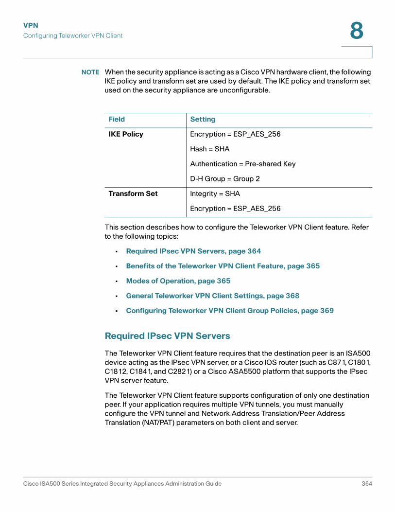
Required IPsec VPN Servers
The Teleworker VPN Client feature requires that the destination peer is an ISA500
device acting as the IPsec VPN server, or a Cisco IOS router (such as C871, C1801,
C1812, C1841, and C2821) or a Cisco ASA5500 platform that supports the IPsec
VPN server feature.
The Teleworker VPN Client feature supports configuration of only one destination
peer. If your application requires multiple VPN tunnels, you must manually
configure the VPN tunnel and Network Address Translation/Peer Address
Translation (NAT/PAT) parameters on both client and server.
Field Setting
IKE Policy Encryption = ESP_AES_256
Hash = SHA
Authentication = Pre-shared Key
D-H Group = Group 2
Transform Set Integrity = SHA
Encryption = ESP_AES_256
Cisco ISA500 Series Integrated Security Appliances Administration Guide 364
VPN
Configuring Teleworker VPN Client 8
Benefits of the Teleworker VPN Client Feature
• Allows dynamic configuration of end-user policy, requiring less manual
configuration by end users and field technicians, thus reducing errors and
further service calls.
• Allows the provider to change equipment and network configurations as
needed, with little or no reconfiguration of the end-user equipment.
• Provides for centralized security policy management.
• Enables large-scale deployments with rapid user provisioning.
• Eliminates the need for end users to purchase and configure external VPN
devices.
• Eliminates the need for end users to install and configure Cisco VPN Client
software on their PCs.
• Offloads the creation and maintenance of the VPN connections from the PC
to the router.
• Reduces interoperability problems between the different PC-based
software VPN clients, external hardware-based VPN solutions, and other
VPN applications.
• Sets up a single IPsec tunnel regardless of the number of multiple subnets
that are supported and the size of the split-include list.
Modes of Operation
The Teleworker VPN Client feature sets the security appliance as a Cisco VPN
hardware client. The Cisco VPN hardware client supports two operation modes:
Client Mode or Network Extension Mode (NEM). The operation mode determines
whether the inside hosts relative to the Cisco VPN hardware client are accessible
from the corporate network over the VPN tunnel. Specifying the operation mode is
mandatory before making a connection because the Cisco VPN hardware client
does not have a default mode.
All modes of operation also optionally support split tunneling, which allows secure
access to corporate resources through the VPN tunnel while also allowing Internet
access through a connection to an Internet Service Provider (ISP) or another
service—thereby eliminating the corporate network from the path for web access.
Refer to the following topics:
• Client Mode, page 366
Cisco ISA500 Series Integrated Security Appliances Administration Guide 365
VPN
Configuring Teleworker VPN Client 8
• Network Extension Mode, page 367
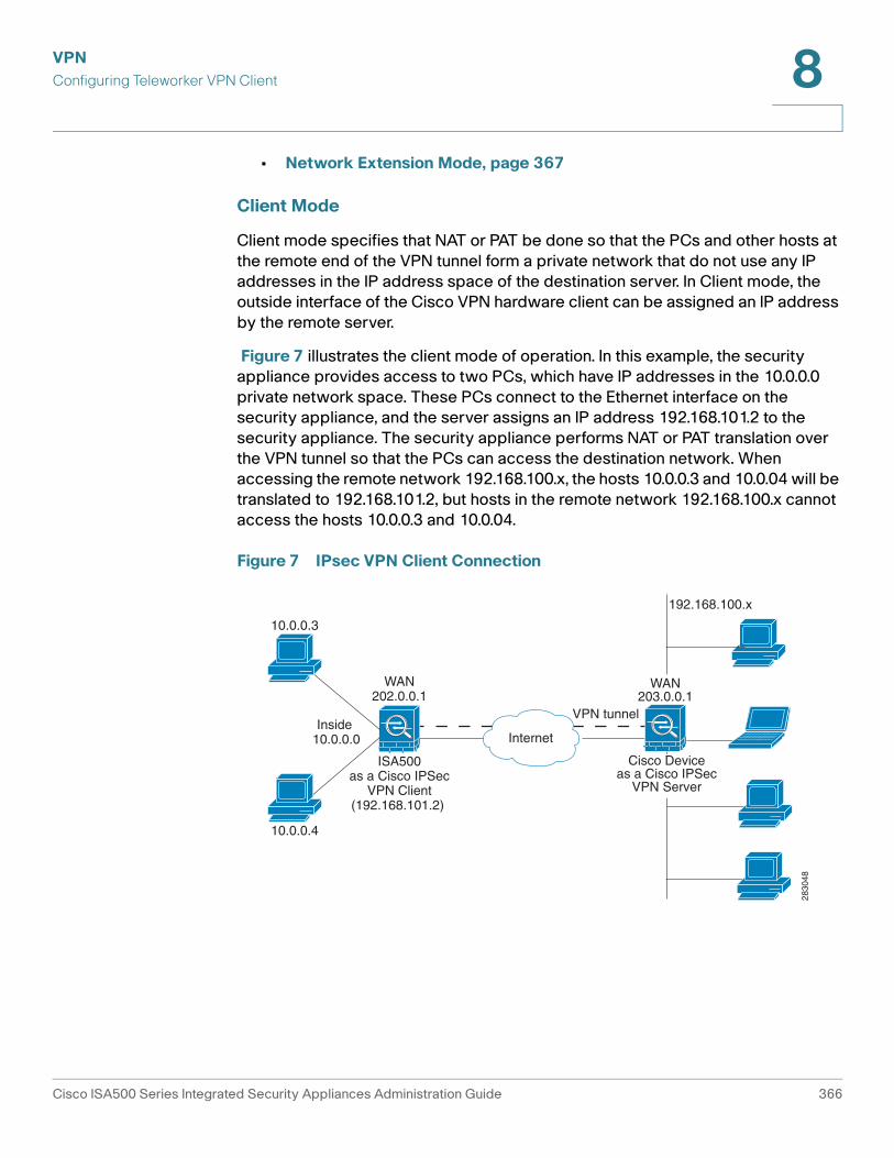
Client Mode
Client mode specifies that NAT or PAT be done so that the PCs and other hosts at
the remote end of the VPN tunnel form a private network that do not use any IP
addresses in the IP address space of the destination server. In Client mode, the
outside interface of the Cisco VPN hardware client can be assigned an IP address
by the remote server.
Figure 7 illustrates the client mode of operation. In this example, the security
appliance provides access to two PCs, which have IP addresses in the 10.0.0.0
private network space. These PCs connect to the Ethernet interface on the
security appliance, and the server assigns an IP address 192.168.101.2 to the
security appliance. The security appliance performs NAT or PAT translation over
the VPN tunnel so that the PCs can access the destination network. When
accessing the remote network 192.168.100.x, the hosts 10.0.0.3 and 10.0.04 will be
translated to 192.168.101.2, but hosts in the remote network 192.168.100.x cannot
access the hosts 10.0.0.3 and 10.0.04.
Figure 7 IPsec VPN Client Connection
ISA500as a Cisco IPSec
VPN Client(192.168.101.2)
Internet
Cisco Deviceas a Cisco IPSec
VPN Server
192.168.100.x
10.0.0.3
10.0.0.4
VPN tunnelInside
10.0.0.0
WAN202.0.0.1
WAN203.0.0.1
2830
48
Cisco ISA500 Series Integrated Security Appliances Administration Guide 366
VPN
Configuring Teleworker VPN Client 8
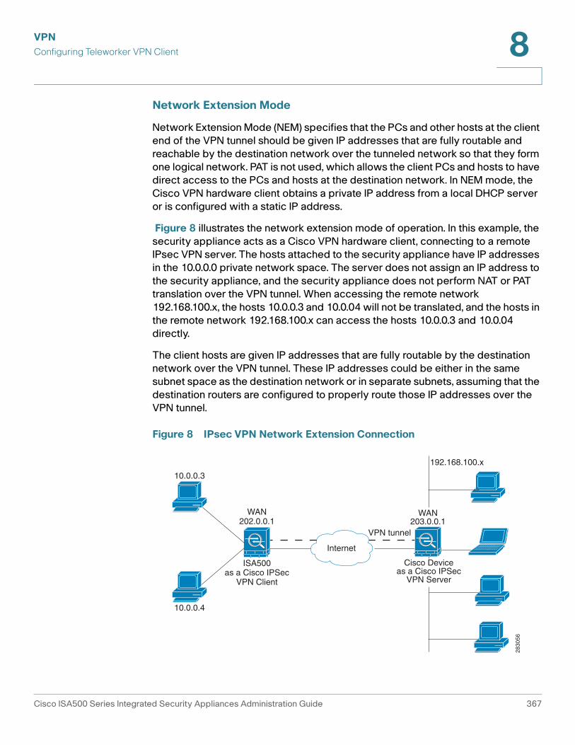
Network Extension Mode
Network Extension Mode (NEM) specifies that the PCs and other hosts at the client
end of the VPN tunnel should be given IP addresses that are fully routable and
reachable by the destination network over the tunneled network so that they form
one logical network. PAT is not used, which allows the client PCs and hosts to have
direct access to the PCs and hosts at the destination network. In NEM mode, the
Cisco VPN hardware client obtains a private IP address from a local DHCP server
or is configured with a static IP address.
Figure 8 illustrates the network extension mode of operation. In this example, the
security appliance acts as a Cisco VPN hardware client, connecting to a remote
IPsec VPN server. The hosts attached to the security appliance have IP addresses
in the 10.0.0.0 private network space. The server does not assign an IP address to
the security appliance, and the security appliance does not perform NAT or PAT
translation over the VPN tunnel. When accessing the remote network
192.168.100.x, the hosts 10.0.0.3 and 10.0.04 will not be translated, and the hosts in
the remote network 192.168.100.x can access the hosts 10.0.0.3 and 10.0.04
directly.
The client hosts are given IP addresses that are fully routable by the destination
network over the VPN tunnel. These IP addresses could be either in the same
subnet space as the destination network or in separate subnets, assuming that the
destination routers are configured to properly route those IP addresses over the
VPN tunnel.
Figure 8 IPsec VPN Network Extension Connection
ISA500as a Cisco IPSec
VPN Client
Internet
Cisco Deviceas a Cisco IPSec
VPN Server
192.168.100.x
10.0.0.3
10.0.0.4
VPN tunnel
WAN202.0.0.1
WAN203.0.0.1
2830
56
Cisco ISA500 Series Integrated Security Appliances Administration Guide 367
VPN
Configuring Teleworker VPN Client 8
General Teleworker VPN Client Settings
This section describes how to enable the Teleworker VPN Client feature, configure
the Auto Initiation Retry settings, and manually connect or disconnect the VPN
connections.
STEP 1 Click VPN > Teleworker VPN Client.
STEP 2 Enter the following information:
• Teleworker VPN Client: Click On to enable the Teleworker VPN Client
feature and hence set the security appliance as a Cisco VPN hardware
client, or click Off to disable it.
NOTE: Enabling the Teleworker VPN Client feature will disable the
Site-to-Site VPN and IPsec Remote Access features and terminate their
connected VPN sessions.
• Auto Initiation Retry: Click On to enable the Auto Initiation Retry feature, or
click Off to disable it.
When you enable Auto Initiation Retry, the security appliance (set as the
Cisco VPN hardware client) first initiates the VPN connection to the primary
server. If there is no response from the primary server after the timeout that
you set in the Retry Interval field, the security appliance then re-initiates the
VPN connection to the primary server. This continues for the number of times
that you set in the Retry Limit field (or until the primary server is connected).
If the primary server cannot be connected after the specified number of
times, the security appliance tries to re-initiate the VPN connection to the
backup servers by following the specified timeout and retry times. If all three
backup servers cannot be connected, repeat the re-initiation process again
and again until an IPsec VPN server can be connected.
When you disable Auto Initiation Retry, the security appliance first initiates
the VPN connection to the primary server. If there is no response from the
primary server in 120 seconds, the security appliance then re-initiates the
VPN connection to the backup servers. If all three backup servers cannot be
connected, repeat the re-initiation process again and again until an IPsec
VPN server can be connected.
• Retry Interval: Specify how often, in seconds, that the security appliance
re-initiates the VPN connection to the primary server and the back servers.
The default value is 120 seconds.
• Retry Limit: Enter the number of times that the security appliance will retry
a VPN connection initiation. The default value is 2.
Cisco ISA500 Series Integrated Security Appliances Administration Guide 368
VPN
Configuring Teleworker VPN Client 8
STEP 3 Click Save to apply your settings.
STEP 4 To manually initiate the VPN connection, click the Connect icon in the Configure
column. By default, the group policy that the Activate Connection on Startup
setting is enabled will automatically initiate the VPN connection when the security
appliance starts up. Only one VPN connection can be active at a time.
STEP 5 To manually terminate the VPN connection, click the Disconnect icon.
Configuring Teleworker VPN Client Group Policies
To be able to complete the configuration of a Teleworker VPN Client group policy,
you must have the following information ready.
• IPsec VPN server’s IP address or hostname.
• IPsec VPN server’s group policy name.
• Pre-shared key or digital certificates for IKE authentication.
NOTE Up to 16 Teleworker VPN Client group policies can be configured on the security
appliance. You can create multiple group polices to connect to different VPN
servers but only one VPN connection can be active at a time.
STEP 1 Click VPN > Teleworker VPN Client.
STEP 2 To add a group policy, click Add.
Other Options: To edit an entry, click the Edit (pencil) icon. To delete an entry, click
the Delete (x) icon. To delete multiple entries, check them and click Delete.
The Teleworker VPN Client - Add/Edit window opens.
STEP 3 In the Basic Settings tab, enter the following information:
• Description: Enter the name for the group policy.
• Server (Remote Address): Enter the IP address or domain name of the
remote IPsec VPN server.
• Activate Connection on Startup: Click On to automatically initiate the VPN
connection when the security appliance starts up, or click Off to disable it.
Only one VPN connection can be active on startup.
Cisco ISA500 Series Integrated Security Appliances Administration Guide 369
VPN
Configuring Teleworker VPN Client 8
• IKE Authentication Method: The VPN client must be properly authenticated
before it can access the remote network. Choose one of the following
authentication methods:
- Pre-shared Key: Choose this option if the IPsec VPN server uses a
simple, password-based key to authenticate and then enter the following
information:
Group Name: Enter the name of the IPsec Remote Access group policy
that is defined on the IPsec VPN server. The security appliance will use
this group policy to establish the VPN connection with the IPsec VPN
server. The IPsec VPN server pushes the security settings over the VPN
tunnel to the security appliance.
Password: Enter the pre-shared key specified in the selected group
policy to establish a VPN connection. The pre-shared key must be
entered exactly the same here and on the IPsec VPN server.
- Certificate: Choose this option if the IPsec VPN server uses the digital
certificate from a third party Certificate Authority (CA) to authenticate.
Select a CA certificate as your local certificate from the Local Certificate
drop-down list and select the CA certificate used on the remote IPsec
VPN server as the remote certificate from the Peer Certificate
drop-down list for authentication.
NOTE: You must have valid CA certificates imported on your security
appliance before choosing this option. Go to the Device Management >
Certificate Management page to import the CA certificates. See
Managing Certificates for Authentication, page 418.
• Mode: The operation mode determines whether the inside hosts relative to
the Cisco VPN hardware client are accessible from the corporate network
over the VPN tunnel. Specifying an operation mode is mandatory before
making a VPN connection because the Cisco VPN hardware client does not
have a default mode. For more information about the operation mode, see
Modes of Operation, page 365.
- Choose Client if you want the PCs and other devices on the security
appliance’s inside networks to form a private network with private IP
addresses. Network Address Translation (NAT) and Port Address
Translation (PAT) will be used. Devices outside the LAN will not be able to
ping devices on the LAN, or reach them directly.
- Choose NEM (Network Extension Mode) if you want the devices
connected to the inside interfaces to have IP addresses that are routable
and reachable by the destination network. The devices at both ends of
Cisco ISA500 Series Integrated Security Appliances Administration Guide 370
VPN
Configuring Teleworker VPN Client 8
the connection will form one logical network. PAT will be automatically
disabled, allowing the PCs and hosts at both ends of the connection to
have direct access to one another.
• VLAN: If you choose NEM, specify the VLAN that permits access from and
to the private network of the IPsec VPN server.
• User Name: Enter the username used by the Teleworker VPN client to
establish a VPN connection.
• User Password: Enter the password used by the Teleworker VPN client to
establish a VPN connection.
STEP 4 In the Zone Access Control tab, you can control access from the zones in your
network to the remote network if the Teleworker VPN client works in Client mode.
Click Permit to permit access, or click Deny to deny access.
NOTE: The VPN firewall rules that are automatically generated by the zone access
control settings will be added to the list of firewall rules with the priority higher
than the default firewall rules, but lower than the custom firewall rules.
STEP 5 In the Advanced Settings tab, enter the following information.
• Backup Server 1/2/3: Enter the IP address or hostname for the backup
server. You can specify up to three servers as backup. When the connection
to the primary IPsec VPN server fails, the security appliance can initiate the
VPN connection to the backup servers. The backup server 1 has the highest
priority and the backup server 3 has the lowest priority.
NOTE: The Teleworker VPN client can get the backup servers from the IPsec
VPN server during the tunnel negotiation. The backup servers specified on
the IPsec VPN server have higher priority than the back servers specified on
the Teleworker VPN client. When the primary connection fails, first try to
connect to the backup servers specified on the IPsec VPN server, and then
try to connect to the backup servers specified on the Teleworker VPN client.
• Peer Timeout: Enter the value of detection timeout in seconds. If no
response and no traffic from the primary server or the backup server over
the timeout, declare the peer dead. The default value is 120 seconds.
STEP 6 Click OK to save your settings.
STEP 7 A warning message appears saying “Do you want to make this connection active
when the settings are saved? (Only one connection can be active at a time.)”
Cisco ISA500 Series Integrated Security Appliances Administration Guide 371
VPN
Configuring SSL VPN 8
• If you want to immediately activate the connection after the settings are
saved, click the Activate Connection button. When you create multiple
Teleworker VPN Client group policies at a time, only one connection can be
active after you save your settings. The security appliance will use the group
policy that was last created or edited to initiate the VPN connection.
• If you only want to create the Teleworker VPN client group policy and do not
want to immediately activate the connection after the settings are saved,
click the Do Not Activate button. You can click the Connect icon to manually
establish the VPN connection.
NOTE: This feature is different from the Active Connection on Startup
feature. It is used to activate the connection immediately after the settings
are saved, but the Activate Connection on Startup feature is used to activate
the connection when the security appliance starts up.
STEP 8 Click Save to apply your settings.
Configuring SSL VPN
SSL VPN is a flexible and secure way to extend network resources to virtually any
remote user. The security appliance supports the SSL VPN feature, and
interoperates with the Cisco AnyConnect Secure Mobility Client software.
A valid security license is required to support SSLVPN with mobile devices such
as smart phones and tablets. For more information, see Activating Security
Services, page 293.
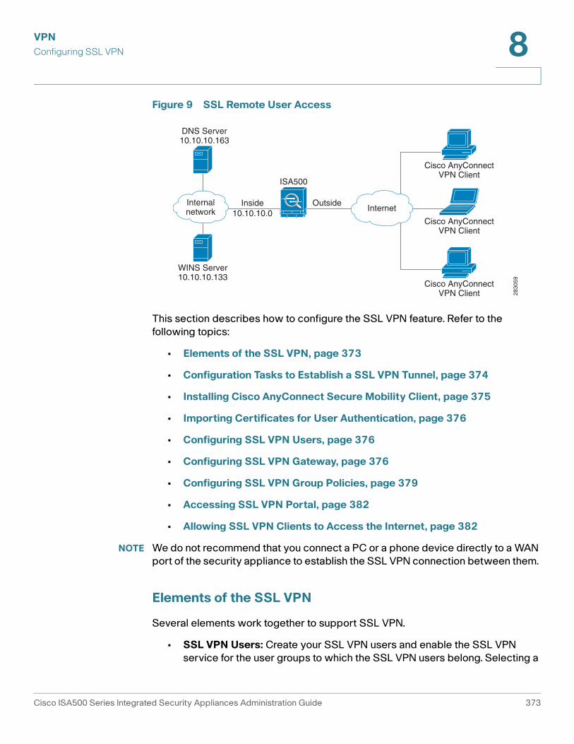
Figure 9 shows an example of SSL VPN. Users can remotely access the network
by using the Cisco AnyConnect Secure Mobility Client software. When the SSL
VPN tunnel is established, each user will have an IP address on the internal
network.
Cisco ISA500 Series Integrated Security Appliances Administration Guide 372
VPN
Configuring SSL VPN 8
Figure 9 SSL Remote User Access
This section describes how to configure the SSL VPN feature. Refer to the
following topics:
• Elements of the SSL VPN, page 373
• Configuration Tasks to Establish a SSL VPN Tunnel, page 374
• Installing Cisco AnyConnect Secure Mobility Client, page 375
• Importing Certificates for User Authentication, page 376
• Configuring SSL VPN Users, page 376
• Configuring SSL VPN Gateway, page 376
• Configuring SSL VPN Group Policies, page 379
• Accessing SSL VPN Portal, page 382
• Allowing SSL VPN Clients to Access the Internet, page 382
NOTE We do not recommend that you connect a PC or a phone device directly to a WAN
port of the security appliance to establish the SSL VPN connection between them.
Elements of the SSL VPN
Several elements work together to support SSL VPN.
• SSL VPN Users: Create your SSL VPN users and enable the SSL VPN
service for the user groups to which the SSL VPN users belong. Selecting a
Inside10.10.10.0
Outside
DNS Server10.10.10.163
WINS Server10.10.10.133
InternetInternalnetwork
ISA500
Cisco AnyConnectVPN Client
Cisco AnyConnectVPN Client
Cisco AnyConnectVPN Client 28
3059
Cisco ISA500 Series Integrated Security Appliances Administration Guide 373
VPN
Configuring SSL VPN 8
SSL VPN group policy can enable the SSL VPN service for a user group. All
members of the user group at remote sites can establish the SSL VPN
tunnels based on the selected SSL VPN group policy. See Configuring SSL
VPN Users, page 376.
• SSL VPN Group Policies: Create your SSL VPN group policies. The SSL
VPN group policy is used to establish the SSL VPN tunnel to access your
network resources. See Configuring SSL VPN Group Policies, page 379.
• Cisco AnyConnect Secure Mobility Client: The Cisco AnyConnect Secure
Mobility Client is the next-generation VPN client, providing remote users
with secure VPN connections to the SSL VPN gateway. See Installing
Cisco AnyConnect Secure Mobility Client, page 375.
Configuration Tasks to Establish a SSL VPN Tunnel
You need to complete below configuration tasks to establish the SSL VPN tunnel.
• Download and install the Cisco AnyConnect Secure Mobility Client
software on remote user’s PC. See Installing Cisco AnyConnect Secure
Mobility Client, page 375.
• (Optional) Import the certificates to your security appliance used for user
authentication. See Importing Certificates for User Authentication,
page 376.
• Enable the SSL VPN feature and configure the SSL VPN gateway settings.
See Configuring SSL VPN Gateway, page 376.
• Define the SSL VPN group policies. See Configuring SSL VPN Group
Policies, page 379.
• Create your SSL VPN users and user groups and specify the SSL VPN
group policy for each SSL VPN user group. See Configuring SSL VPN
Users, page 376.
• Launch the Cisco AnyConnect Secure Mobility Client software on user’s
PC, enter the address pair “Gateway IP address:Gateway port number” to
connect to the remote SSL VPN gateway, and then enter the authentication
credentials to establish the SSL VPN connection.
• View information for all active SSL VPN sessions. See Viewing SSL VPN
Status, page 337.
Cisco ISA500 Series Integrated Security Appliances Administration Guide 374
VPN
Configuring SSL VPN 8
Installing Cisco AnyConnect Secure Mobility Client
You can set up a PC to run the Cisco AnyConnect Secure Mobility Client software
by installing the client software for the appropriate operating system directly on
the user’s PC. The user starts the Cisco AnyConnect Secure Mobility Client
software and provides the authentication credentials to establish the VPN
connection.
The security appliance supports the Cisco AnyConnect Secure Mobility Client
Release 3.0 (use for SSL only). The Cisco AnyConnect Secure Mobility Client is
compatible with the following platforms:
• Windows 7 (32-bit and 64-bit)
• Windows Vista (32-bit and 64-bit)
• Windows XP SP2+ (32-bit and 64-bit)
• Linux Intel (2.6.x kernel)
• Mac OS X 10.5, 10.6.x, and 10.7
You can find the software installers from the CD that is packed with the security
appliance. The CD includes AnyConnect packages for Windows, Mac OS X, and
Linux. Choose correct AnyConnect package from the CD to download depending
on your operating system.
You can also download the Cisco AnyConnect Secure Mobility Client software by
going to this site:
http://www.cisco.com/cisco/software/type.html?mdfid=283000185&catid=null
You must log in and possess a valid service contract in order to access the Cisco
AnyConnect Secure Mobility Client software. A 3-year Cisco Small Business
Support Service Contract (CON-SBS-SVC2) is required to download the client
software from Cisco.com. If you don’t have one, contact your partner or reseller, or
Cisco Support for more information.
For more information about how to download, install, and configure the Cisco
AnyConnect Secure Mobility Client software, go to this site:
http://www.cisco.com/en/US/products/ps10884/tsd_products_support_series_h
ome.html
NOTE The Cisco AnyConnect Secure Mobility Client will keep the reconnecting state
after the cable of the WAN interface on the server is plugged out and then is
plugged in. In this case, you must first stop the client reconnecting, and then
manually connect to the SSL VPN server.
Cisco ISA500 Series Integrated Security Appliances Administration Guide 375
VPN
Configuring SSL VPN 8
Importing Certificates for User Authentication
The SSL VPN gateway holds a CA certificate that is presented to the SSL VPN
clients when the SSL VPN clients first connect to the gateway. The purpose of this
certificate is to authenticate the server. You can use the default certificate or an
imported certificate for authentication. For information on importing the
certificates, see Managing Certificates for Authentication, page 418.
Configuring SSL VPN Users
ISA550 and ISA550W support 25 SSL VPN users. ISA570 and ISA570W support
50 SSL VPN users. To configure the users and user groups for SSL VPN access,
go to the Users > Users and Groups page.
You can assign all SSL VPN users to one user group. However, if you have multiple
SSL VPN group policies, you can create multiple user groups and specify different
SSL VPN group policies for them. Specifying a SSL VPN group policy for a user
group can enable the SSL VPN service for all members of the user group. For
complete details, see Configuring Users and User Groups, page 389.
According to the user authentication settings specified on the security appliance,
the SSL VPN users can be authenticated by the local database or external AAA
server (such as Active Directory, LDAP, or RADIUS). For information on configuring
the user authentication settings, see Configuring User Authentication Settings,
page 393.
Configuring SSL VPN Gateway
Use the SSL VPN Configuration page to enable the SSL VPN feature and configure
the SSL VPN gateway settings.
STEP 1 Click VPN > SSL Remote User Access > SSL VPN Configuration.
The SSL VPN Configuration window opens.
STEP 2 Click On to enable the SSL VPN feature and hence set the security appliance as a
SSL VPN server, or click Off to disable it.
STEP 3 In the Mandatory Gateway area, enter the following information:
• Gateway Interface: Choose the WAN port that traffic passes through over
the SSL VPN tunnels.
Cisco ISA500 Series Integrated Security Appliances Administration Guide 376
VPN
Configuring SSL VPN 8
• Gateway Port: Enter the port number used for the SSL VPN gateway. By
default, SSL operates on port 443. However, the SSL VPN gateway should
be flexible to operate on a user defined port. The firewall should permit the
port to ensure delivery of packets destined for the SSL VPN gateway. The
SSL VPN clients need to enter the entire address pair “Gateway IP address:
Gateway port number” for connecting purposes.
• Certificate File: Choose the default certificate or an imported certificate to
authenticate users who try to access your network resource through the
SSL VPN tunnels. For information on importing the certificates, see
Managing Certificates for Authentication, page 418.
• Client Address Pool: The SSL VPN gateway has a configurable address
pool that is used to allocate IP addresses to remote VPN clients. Enter the IP
address pool for all remote clients. The client is assigned an IP address by
the SSL VPN gateway.
NOTE: Configure an IP address range that does not directly overlap with any
of addresses on your local network.
• Client Netmask: Enter the IP address of the netmask used for SSL VPN
clients. The client netmask can only be one of 255.255.255.0,
255.255.255.128, and 255.255.255.192.
The Client Address Pool is used with the Client Netmask. The following table
displays the valid settings for entering the client address pool and the client
netmask.
If they are set as follows, then the SSL VPN client will get a VPN address
whose range is from 10.10.10.1 to 10.10.10.254.
- Client Address Pool = 10.10.10.0
- Client Netmask = 255.255.255.0
• Client Internet Access: Check this box to automatically create advanced
NAT rules to allow SSL VPN clients to access the Internet. If you uncheck this
box, you can manually create advanced NAT rules. See Allowing SSL VPN
Clients to Access the Internet, page 382.
Client Netmask Client Address Pool
255.255.255.0 x.x.x.0
255.255.255.128 x.x.x.0, or x.x.x.128
255.255.255.192 x.x.x.0, x.x.x.64, x.x.x.128, or x.x.x.192
Cisco ISA500 Series Integrated Security Appliances Administration Guide 377
VPN
Configuring SSL VPN 8
• Client Domain: Enter the domain name that should be pushed to SSL VPN
clients.
• Login Banner: After the users logged in, a configurable login banner is
displayed. Enter the message text to display along with the banner.
STEP 4 In the Optional Gateway area, enter the following information:
• Idle Timeout: Enter the timeout value in seconds that the SSL VPN session
can remain idle. The default value is 2100 seconds.
• Session Timeout: Enter the timeout value in seconds that a SSL VPN
session can remain active. The default value is 0 seconds, which indicates
that the SSL VPN session can always be active.
• Client DPD Timeout: Dead Peer Detection (DPD) allows detection of dead
peers. Enter the DPD timeout that a session will be maintained with a
nonresponsive remote client. The default value is 300 seconds.
• Gateway DPD Timeout: Enter the DPD timeout that a session will be
maintained with a nonresponsive SSL VPN gateway. The default value is 300
seconds.
NOTE: If the SSL VPN gateway has no response over two or three times of
the DPD timeout, the SSL VPN session will be terminated.
• Keep Alive: Enter the interval, in seconds, at which the SSL VPN client will
send keepalive messages. These messages ensure that the SSL VPN
connection remains open, even if the client’s maximum idle time is limited by
an intermediate device, such as a proxy, firewall or NAT device.
• Lease Duration: Enter the amount of time after which the SSL VPN client
must send an IP address lease renewal request to the server. The default
value is 43200 seconds.
• Max MTU: Enter the maximum transmission unit for the session. The default
value is 1406 bytes.
• Rekey Method: Specify the session rekey method (SSL or New Tunnel).
Rekey allows the SSL keys to be renegotiated after the session has been
established.
• Rekey Interval: Enter the frequency of the rekey in this field. The default
value is 3600 seconds.
STEP 5 Click Save to apply your settings.
Cisco ISA500 Series Integrated Security Appliances Administration Guide 378
VPN
Configuring SSL VPN 8
Configuring SSL VPN Group Policies
All members of the SSL VPN user group can establish the SSL VPN tunnels based
on the specified SSL VPN group policy to access your network resources.
NOTE Up to 32 SSL VPN group policies can be configured on the security appliance.
STEP 1 Click VPN > SSL Remote User Access > SSL VPN Group Policies.
The SSL VPN Group Policies window opens. The default and custom SSL VPN
group policies are listed in the table.
STEP 2 To add a new SSL VPN group policy, click Add.
Other options: To edit an entry, click the Edit (pencil) icon. To delete an entry, click
the Delete (x) icon. To delete multiple entries, check them and click Delete. The
default SSL VPN group policy (SSLVPNDefaultPolicy) cannot be deleted.
The SSL VPN Group Policy - Add/Edit window opens.
STEP 3 In the Basic Settings tab, enter the following information:
• Policy Name: Enter the name for the SSL VPN group policy.
• Primary DNS: Enter the IP address of the primary DNS server.
• Secondary DNS: Enter the IP address of the secondary DNS server.
• Primary WINS: Enter the IP address of the primary WINS server.
• Secondary WINS: Enter the IP address of the secondary WINS server.
STEP 4 In the IE Proxy Settings tab, enter the following information:
The SSL VPN gateway can specify several Microsoft Internet Explorer (MSIE)
proxies for client PCs. If these settings are enabled, IE on the client PC is
automatically configured with these settings.
• IE Proxy Policy: Choose one of the following IE proxy policies:
- None: Allows the browser to use no proxy settings.
- Auto: Allows the browser to automatically detect the proxy settings.
- Bypass-Local: Allows the browser to bypass the proxy settings that are
configured on the remote user.
- Disable: Disables the MSIE proxy settings.
Cisco ISA500 Series Integrated Security Appliances Administration Guide 379
VPN
Configuring SSL VPN 8
• Address: If you choose Bypass-Local or Auto, enter the IP address or
domain name of the MSIE proxy server.
• Port: Enter the port number of the MSIE proxy server.
• IE Proxy Exception: You can specify the exception hosts for IE proxy
settings. This option allows the browser not to send traffic for the given
hostname or IP address through the proxy. To add an entry, enter the IP
address or domain name of an exception host and click Add. To delete an
entry, select it and click Delete.
STEP 5 In the Split Tunneling Settings area, enter the following information:
Split tunneling permits specific traffic to be carried outside of the SSL VPN tunnel.
Traffic is either included (resolved in tunnel) or excluded (resolved through the ISP
or WAN connection). Tunnel resolution configuration is mutually exclusive. An IP
address cannot be both included and excluded at the same time.
• Enable Split Tunneling: By default, all traffic from the host is directed
through the VPN tunnel. Check this box to enable the split tunneling feature
so that the VPN tunnel is used only for traffic that is specified by the client
routes.
• Split Selection: Choose one of the following options:
- Include Traffic: Allows you to add the client routes on the SSL VPN client
so that only traffic to the destination networks can be redirected through
the VPN tunnel. To add a client route, enter the destination subnet to
which a route is added on the SSL VPN client in the Address field and the
subnet mask for the destination network in the Netmask field, and then
click Add.
- Exclude Traffic: Allows you to exclude the destination networks on the
SSL VPN client. Traffic to the destination networks is redirected using the
SSL VPN client’s native network interface (resolved through the ISP or
WAN connection). To add a destination subnet, enter the destination
subnet to which a route is excluded on the SSL VPN client in the Address
field and the subnet mask for the excluded destination in the Netmask
field, and then click Add.
NOTE: To exclude the destination networks, make sure that the Exclude
Local LAN feature is enabled on the Cisco AnyConnect Secure Mobility
clients.
Cisco ISA500 Series Integrated Security Appliances Administration Guide 380
VPN
Configuring SSL VPN 8
- Exclude Local LAN: If you choose Exclude Traffic, check the box to
permit remote users to access their local LANs without passing through
VPN tunnel, or uncheck the box to deny remote users to access their local
LANs without passing through VPN tunnel.
NOTE: To exclude local LANs, make sure that the Exclude Local LAN
feature is enabled on both the SSL VPN server and the AnyConnect
clients.
• Split DNS: Split DNS can direct DNS packets in clear text over the Internet
to domains served through an external DNS (serving your ISP) or through the
VPN tunnel to domains served by the corporate DNS.
For example, a query for a packet destined for corporate.com would go
through the VPN tunnel to the DNS that serves the private network, while a
query for a packet destined for myfavoritesearch.com would be handled by
the ISP's DNS. To use Split DNS, you must also have split tunneling
configured.
To add a domain for tunneling packets to destinations in the private network,
enter the IP address or domain name in the field and click Add. To delete a
domain, select it and click Delete.
STEP 6 In the Zone-based Firewall Settings area, you can control access from the SSL
VPN clients to the zones over the VPN tunnels. Click Permit to permit access, or
click Deny to deny access.
NOTE: The VPN firewall rules that are automatically generated by the zone-based
firewall settings will be added to the list of firewall rules with the priority higher
than the default firewall rules, but lower than the custom firewall rules.
STEP 7 Click OK to save your settings.
STEP 8 Click Save to apply your settings.
Cisco ISA500 Series Integrated Security Appliances Administration Guide 381
VPN
Configuring SSL VPN 8
Accessing SSL VPN Portal
The SSL VPN portal provides a message to remind users to install the Cisco
AnyConnect Secure Mobility Client software to connect to the SSL VPN server.
You can find the software installers from the CD that is packed with the device or
download the software installers from Cisco.com. See Installing Cisco
AnyConnect Secure Mobility Client, page 375.
You can access the SSL VPN portal via a web browser from the WAN side by
using the HTTPS protocol. You must first enable the SSL VPN feature on the
security appliance and then enter the entire address pair “Gateway IP
address:Gateway port number” in the address bar to access the SSL VPN portal.
Allowing SSL VPN Clients to Access the Internet
Enabling Client Internet Access will automatically create advanced NAT rules to
allow SSL VPN clients to access the Internet over SSL VPN tunnels. This section
provides an example of manually configuring advanced NAT rules to allow SSL
VPN clients to access the Internet over SSL VPN tunnels.
STEP 1 Assuming that you enable the SSL VPN feature and configure the gateway
settings as follows.
STEP 2 If only a single WAN interface is configured, go to the Firewall > NAT > Advanced
NAT page to create an advanced NAT rule as follows.
Field Setting
Gateway Interface WAN1
Gateway Port 443
Certificate File default
Client Address Pool 192.168.200.0
Client Netmask 255.255.255.0
Field Setting
Name SSLVPN_to_WAN1
Cisco ISA500 Series Integrated Security Appliances Administration Guide 382
VPN
Configuring SSL VPN 8
STEP 3 If two WAN interfaces are configured and the WAN redundancy is set as the Load
Balancing mode, go to the Firewall > NAT > Advanced NAT page to create two
advanced NAT rule as follows.
Enable On
From Any
To WAN1
Original Source
Address
SSLVPN_ADDRESS_POOL
Original Destination
Address
Any
Original Services Any
Translated Source
Address
WAN1_IP
Translated
Destination Address
Any
Translated Services Any
Field Setting
Field Setting
Name SSLVPN_to_WAN1
Enable On
From Any
To WAN1
Original Source
Address
SSLVPN_ADDRESS_POOL
Original Destination
Address
Any
Original Services Any
Cisco ISA500 Series Integrated Security Appliances Administration Guide 383
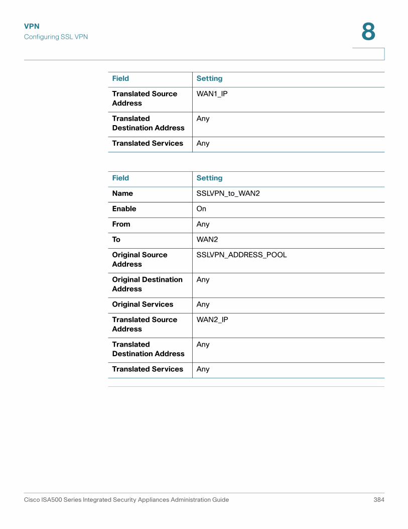
VPN
Configuring SSL VPN 8
Translated Source
Address
WAN1_IP
Translated
Destination Address
Any
Translated Services Any
Field Setting
Field Setting
Name SSLVPN_to_WAN2
Enable On
From Any
To WAN2
Original Source
Address
SSLVPN_ADDRESS_POOL
Original Destination
Address
Any
Original Services Any
Translated Source
Address
WAN2_IP
Translated
Destination Address
Any
Translated Services Any
Cisco ISA500 Series Integrated Security Appliances Administration Guide 384
VPN
Configuring L2TP Server 8
Configuring L2TP Server
Layer 2 Tunneling Protocol (L2TP) is a VPN tunneling protocol that allows remote
clients to use the public IP network to securely communicate with private
corporate network servers. L2TP uses PPP over UDP (port 1701) to tunnel the
data.
L2TP protocol is based on the client and server model. The security appliance can
terminate the L2TP-over-IPsec connections from incoming Microsoft Windows
clients.
STEP 1 Click VPN > L2TP Server.
STEP 2 Click On to enable L2TP server, or click Off to disable it.
STEP 3 If you enable L2TP server, enter the following information:
• Listen WAN Interface: Choose the WAN interface on which the L2TP server
listens to accept the incoming L2TP VPN connection.
• User Name: Enter the username that all L2TP clients use to access the L2TP
server.
• Password: Enter the password that all L2TP clients use to access the L2TP
server.
NOTE: All L2TP clients use the same username and password to log into the
L2TP server.
• MTU: Enter the MTU size in bytes that can be sent over the network. The
valid range is 128 to 1400 bytes. The default value is 1400 bytes.
• Authentication Method: Choose either CHAP (Challenge Handshake
Authentication Protocol) or PAP (Password Authentication Protocol), or both
to authenticate the L2TP clients. Click On to enable CHAP or PAP, or click Off
to disable it.
• Address Pool: The L2TP server assigns IP addresses to all L2TP clients.
Enter the starting IP address in the Start IP Address field and the ending IP
address in the End IP Address field.
• DNS1 IP Address: Enter the IP address of the primary DNS server.
• DNS2 IP Address: Optionally, enter the IP address of the secondary DNS
server.
Cisco ISA500 Series Integrated Security Appliances Administration Guide 385
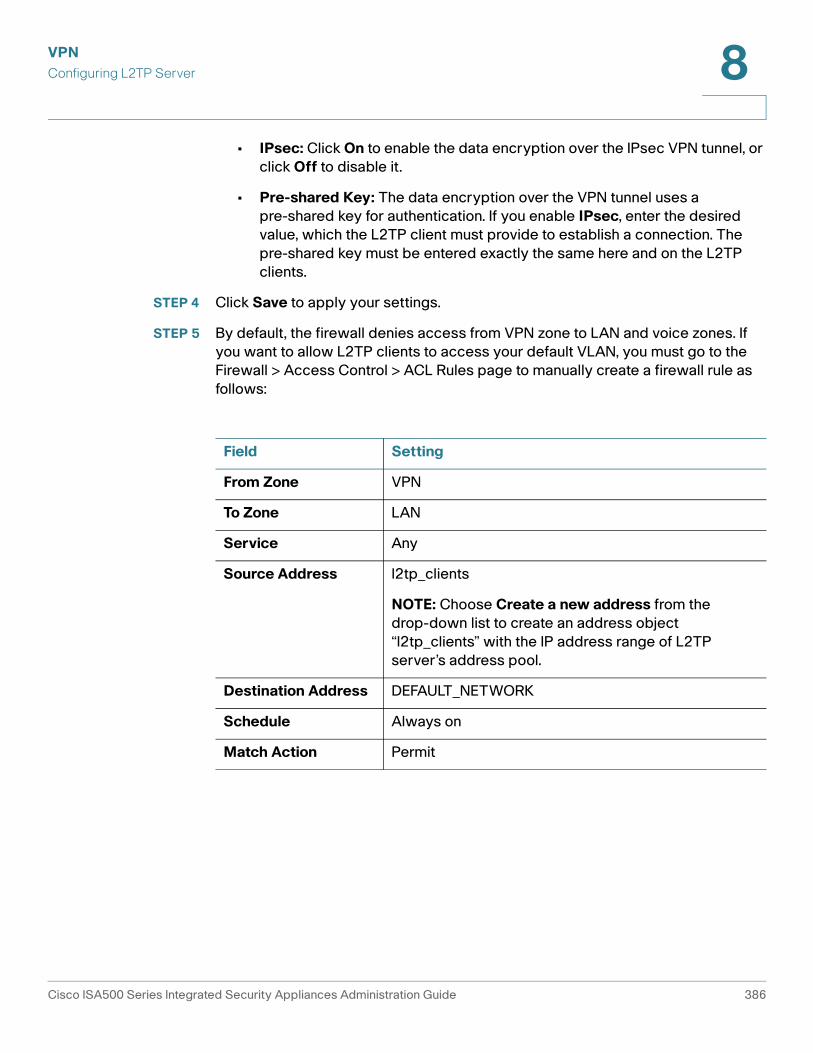
VPN
Configuring L2TP Server 8
• IPsec: Click On to enable the data encryption over the IPsec VPN tunnel, or
click Off to disable it.
• Pre-shared Key: The data encryption over the VPN tunnel uses a
pre-shared key for authentication. If you enable IPsec, enter the desired
value, which the L2TP client must provide to establish a connection. The
pre-shared key must be entered exactly the same here and on the L2TP
clients.
STEP 4 Click Save to apply your settings.
STEP 5 By default, the firewall denies access from VPN zone to LAN and voice zones. If
you want to allow L2TP clients to access your default VLAN, you must go to the
Firewall > Access Control > ACL Rules page to manually create a firewall rule as
follows:
Field Setting
From Zone VPN
To Zone LAN
Service Any
Source Address l2tp_clients
NOTE: Choose Create a new address from the
drop-down list to create an address object
“l2tp_clients” with the IP address range of L2TP
server’s address pool.
Destination Address DEFAULT_NETWORK
Schedule Always on
Match Action Permit
Cisco ISA500 Series Integrated Security Appliances Administration Guide 386
VPN
Configuring VPN Passthrough 8
Configuring VPN Passthrough
Use the VPN Passthrough page to configure VPN Passthrough to allow VPN traffic
that originates from VPN clients to pass through your security appliance. Use this
feature if there are devices behind your security appliance that need the IPSec
tunnels to be set up independently, such as connecting to another router on the
WAN.
STEP 1 Click VPN > VPN Passthrough.
The VPN Passthrough window opens.
STEP 2 Specify the type of traffic that can pass through the security appliance:
• Layer-2 Tunneling Protocol (L2TP): Click On to allow L2TP tunnels to pass
through the security appliance, or click Off to disable it.
• Point-to-Point Tunneling Protocol (PPTP): Click On to allow PPTP tunnels
to pass through the security appliance, or click Off to disable it.
• Internet Protocol Security (IPsec): Click On to allow IP security tunnels to
pass through the security appliance, or click Off to disable it.
STEP 3 Click Save to apply your settings.
Cisco ISA500 Series Integrated Security Appliances Administration Guide 387