VLSI Design & Embedded Systems Conference January 2015 Bengaluru, India Diagnostic Tests for...
23
VLSI Design & Embedded Systems Conference January 2015 Bengaluru, India Diagnostic Tests for Pre-Bond TSV Defects Bei Zhang Vishwani Agrawal
-
Upload
junior-little -
Category
Documents
-
view
213 -
download
0
Transcript of VLSI Design & Embedded Systems Conference January 2015 Bengaluru, India Diagnostic Tests for...

VLSI Design & Embedded Systems ConferenceJanuary 2015
Bengaluru, India
Diagnostic Tests for Pre-Bond TSV Defects
Bei ZhangVishwani Agrawal
Purpose of Pre-bond TSV Test
04/19/23© VLSI Design & Embedded Systems Conference -
20152
Defects arise in TSV manufacturing. Pre-bond TSV test helps identify defective dies early in the process.
Pre-bond TSV test provides known good die (KGD) information for die-on-die or die-on-wafer or wafer-on-wafer fabrication process.
Outline
• 3D IC Structure and TSV Models• Pre-bond TSV Probing technique• Test Session Generation• Experimental Results• Conclusion
04/19/23© VLSI Design & Embedded Systems Conference -
20153
4
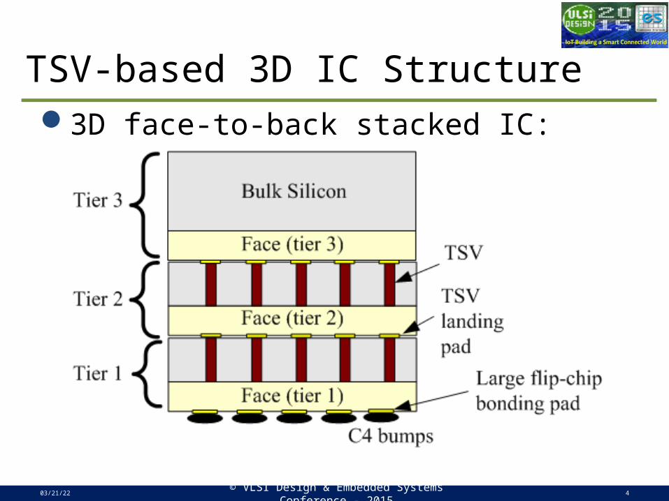
TSV-based 3D IC Structure3D face-to-back stacked IC:
04/19/23© VLSI Design & Embedded Systems Conference -
20154
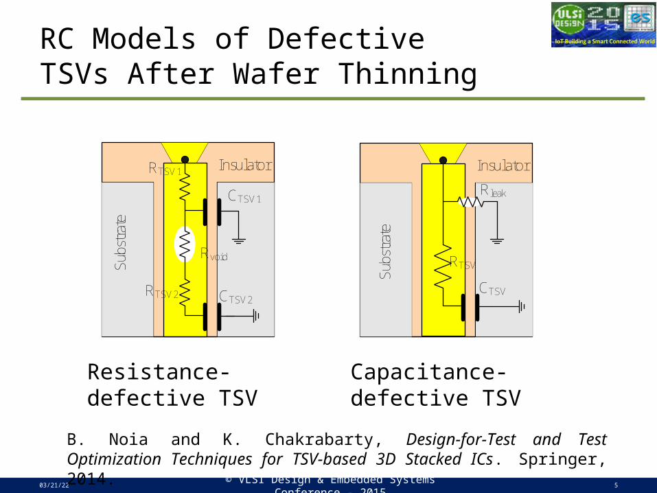
RC Models of DefectiveTSVs After Wafer Thinning
04/19/23© VLSI Design & Embedded Systems Conference -
20155
Resistance-defective TSV Capacitance-defective TSV
Sub
stra
te
InsulatorRTSV1
CTSV2RTSV2
CTSV1
Rvoid
Sub
stra
te
Insulator
CTSV
RTSV
Rleak
B. Noia and K. Chakrabarty, Design-for-Test and Test Optimization Techniques for TSV-based 3D Stacked ICs. Springer, 2014.
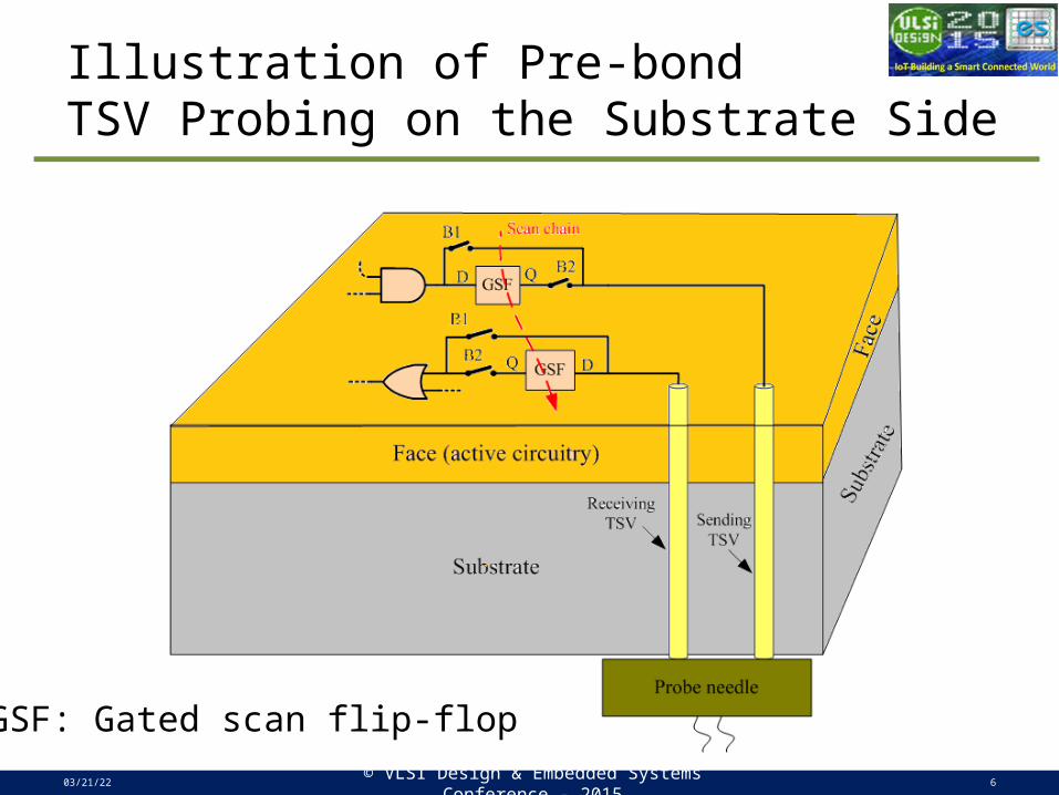
Illustration of Pre-bond TSV Probing on the Substrate Side
04/19/23© VLSI Design & Embedded Systems Conference -
20156
GSF: Gated scan flip-flop
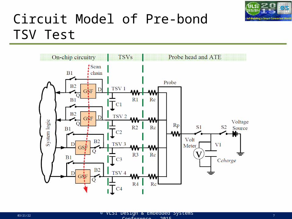
Circuit Model of Pre-bond TSV Test
04/19/23© VLSI Design & Embedded Systems Conference -
20157
04/19/23© VLSI Design & Embedded Systems Conference -
20158
1
1
1
1
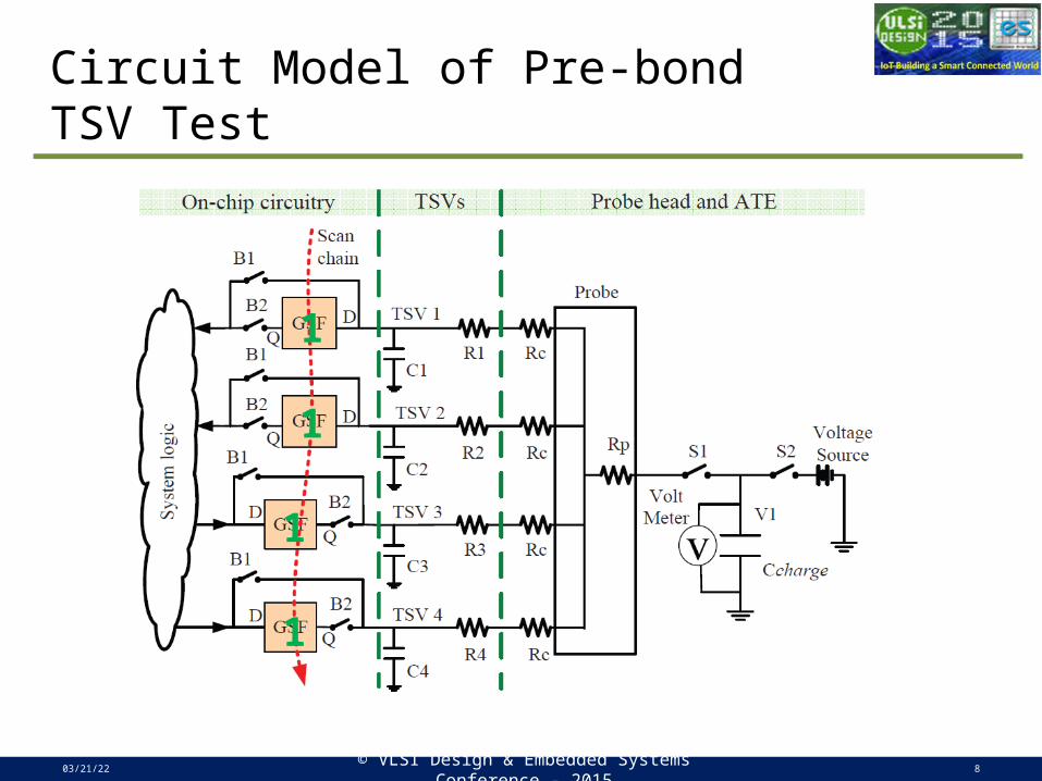
Circuit Model of Pre-bond TSV Test

04/19/23© VLSI Design & Embedded Systems Conference -
20159
1
1
1
1
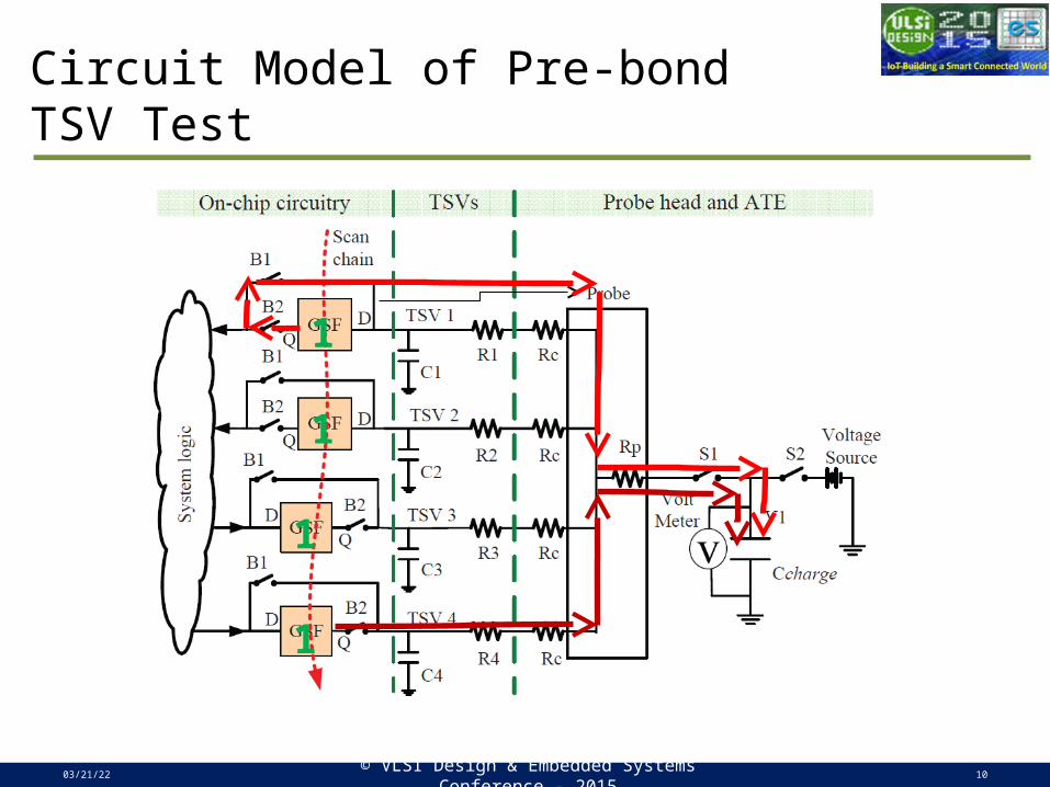
Circuit Model of Pre-bond TSV Test
04/19/23© VLSI Design & Embedded Systems Conference -
201510
1
1
1
1
Circuit Model of Pre-bond TSV Test
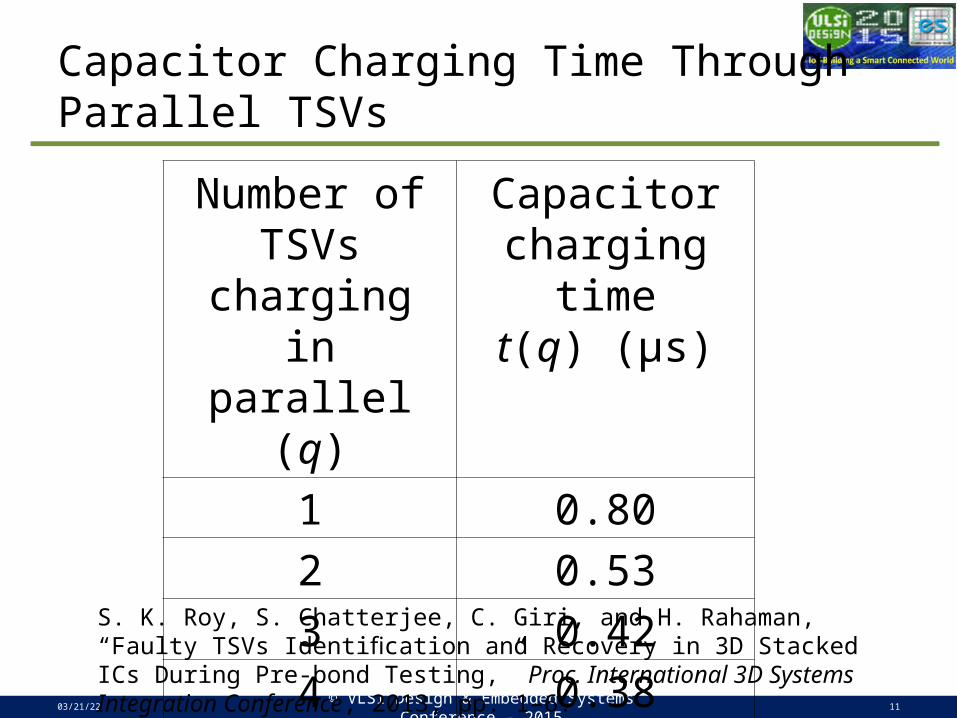
Capacitor Charging Time Through Parallel TSVs
04/19/23© VLSI Design & Embedded Systems Conference -
201511
Number of TSVs charging in parallel (q)
Capacitor charging time
t(q) (μs)1 0.802 0.533 0.424 0.38
S. K. Roy, S. Chatterjee, C. Giri, and H. Rahaman, “Faulty TSVs Identification and Recovery in 3D Stacked ICs During Pre-bond Testing,” Proc. International 3D Systems Integration Conference, 2013, pp. 1–6.
Two Important Observations
1) Any faulty TSV within a parallel test will cause the test to fail but we cannot tell which TSV(s) is (are) faulty.
2) A good parallel test implies that all TSVs within the parallel test are fault-free.
04/19/23© VLSI Design & Embedded Systems Conference -
201512

Terminology
04/19/23© VLSI Design & Embedded Systems Conference -
201513
TSV network TSVs simultaneously contacted by probe.
Test session (Si) TSVs grouped for parallel charging of capacitor.
Maximum number of faulty TSVs in network (m)
m is the number of redundant TSVs within the TSV network.
Session size (q) q is the number of active TSVs within a session.
Resolution (r) r is an upper bound on session size.
Test time of a session (t(q))
Charging time of Ccharge, related to session size.
Fault map (ρ) Fault map represents positions of defective TSVs within the TSV network.
Test Session Generation
Motivation Compared to individual TSV test, large test
time saving is possible if we test TSVs in parallel without losing the capability of identifying up to m faulty TSVs, while guaranteeing that the size of each test session does not exceed the resolution constraint r.
04/19/23© VLSI Design & Embedded Systems Conference -
201514
Test Session Generation
Problem Statement Given:
Test times t(q) for different session sizes q (q [1, r]), and∈Maximum number (m) of faulty TSVs in a
network of T TSVs.Determine: A set of test sessions of size less than r, such that up to m faulty TSVs are uniquely identified and the total test time is minimized.
04/19/23© VLSI Design & Embedded Systems Conference -
201515
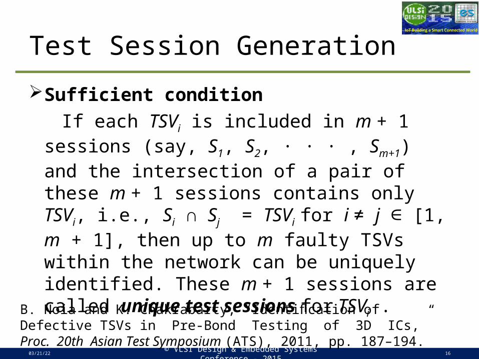
Test Session Generation
Sufficient condition If each TSVi is included in m + 1 sessions (say,
S1, S2, · · · , Sm+1) and the intersection of a pair of these m + 1 sessions contains only TSVi, i.e., Si ∩ Sj = TSVi for i ≠ j [1, ∈ m + 1], then up to m faulty TSVs within the network can be uniquely identified. These m + 1 sessions are called unique test sessions for TSVi .
04/19/23© VLSI Design & Embedded Systems Conference -
201516
B. Noia and K. Chakrabarty, “Identification of Defective TSVs in Pre-Bond Testing of 3D ICs,” Proc. 20th Asian Test Symposium (ATS), 2011, pp. 187–194.
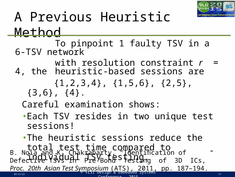
A Previous Heuristic Method To pinpoint 1 faulty TSV in a 6-TSV
network with resolution constraint r = 4, the
heuristic-based sessions are {1,2,3,4}, {1,5,6}, {2,5}, {3,6}, {4}. Careful examination shows:•Each TSV resides in two unique test
sessions! •The heuristic sessions reduce the total test
time compared to individual TSV testing.
04/19/23© VLSI Design & Embedded Systems Conference -
201517
B. Noia and K. Chakrabarty, “Identification of Defective TSVs in Pre-Bond Testing of 3D ICs,” Proc. 20th Asian Test Symposium (ATS), 2011, pp. 187–194.
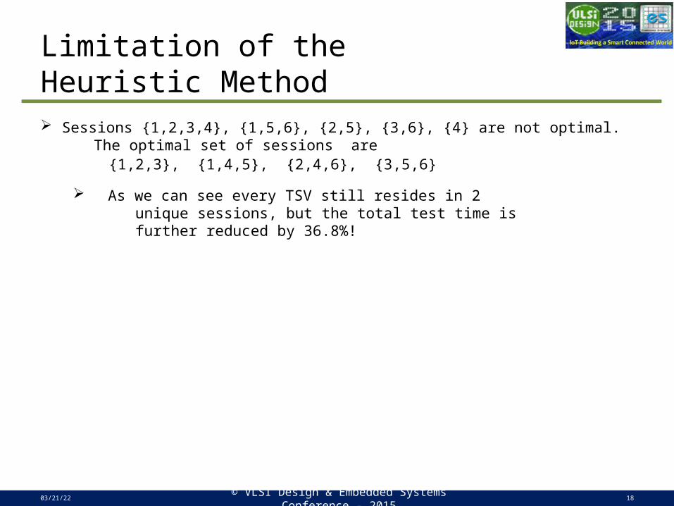
Limitation of the Heuristic Method Sessions {1,2,3,4}, {1,5,6}, {2,5}, {3,6}, {4} are not optimal. The optimal set of sessions are
{1,2,3}, {1,4,5}, {2,4,6}, {3,5,6}
As we can see every TSV still resides in 2 unique sessions, but the total test time is further reduced by 36.8%!
04/19/23© VLSI Design & Embedded Systems Conference -
201518
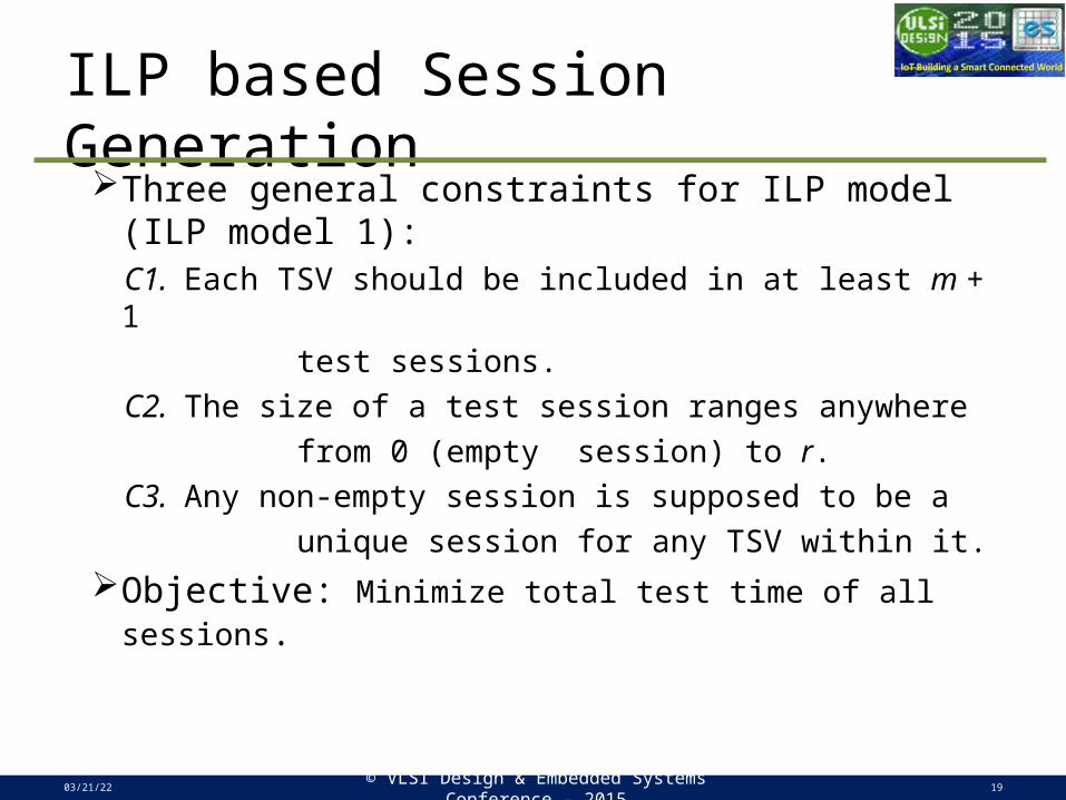
ILP based Session GenerationThree general constraints for ILP model (ILP
model 1): C1. Each TSV should be included in at least m + 1 test sessions. C2. The size of a test session ranges anywhere from 0 (empty session) to r. C3. Any non-empty session is supposed to be a unique session for any TSV within it.Objective: Minimize total test time of all sessions.
04/19/23© VLSI Design & Embedded Systems Conference -
201519

Experimental Results
04/19/23© VLSI Design & Embedded Systems Conference -
201520
Test time comparison for a 20-TSV network
Experimental Results
04/19/23© VLSI Design & Embedded Systems Conference -
201521
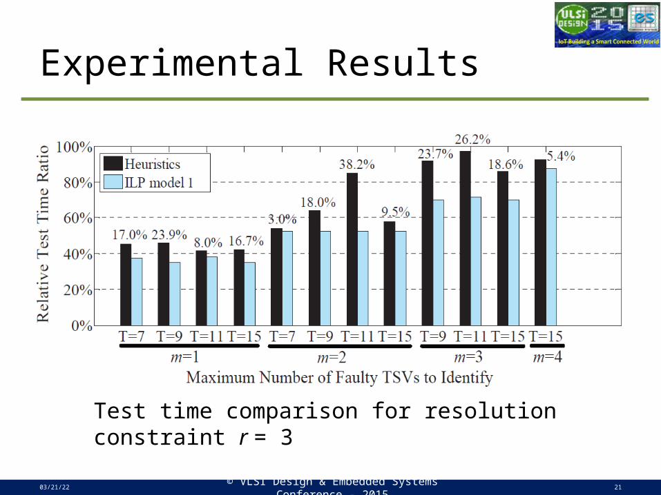
Test time comparison for resolution constraint r = 3

Experimental Results
04/19/23© VLSI Design & Embedded Systems Conference -
201522
Comparison of number of sessions for r = 4
Conclusion
04/19/23© VLSI Design & Embedded Systems Conference -
201523
• An ILP model is proposed to generate near-optimal set of test sessions for pre-bond TSV testing.
• ILP model always reduces pre-bond TSV identification time compared to that of a previous heuristic method.
• Future exploration can be possibly deriving necessary and sufficient conditions to generate globally optimal set of sessions.