VITG Training - 2nd Half.022712 Final€¦ · PCE – 1,000 ppb ANSWER: IEC Commercial Scenario #11...
76
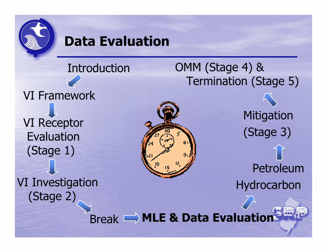
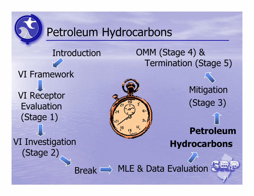
1 Data Evaluation Introduction VI Investigation (Stage 2) VI Receptor Evaluation (Stage 1) VI Framework Break Petroleum Hydrocarbon s MLE & Data Evaluation Mitigation (Stage 3) OMM (Stage 4) & Termination (Stage 5)
Transcript of VITG Training - 2nd Half.022712 Final€¦ · PCE – 1,000 ppb ANSWER: IEC Commercial Scenario #11...
1
Data Evaluation
Introduction
VI Investigation (Stage 2)
VI Receptor Evaluation(Stage 1)
VI Framework
Break
PetroleumHydrocarbon
s
MLE & Data Evaluation
Mitigation (Stage 3)
OMM (Stage 4) & Termination (Stage 5)
2
Data Evaluation
Topics to be discussed:
Data Usability
Multiple Lines of Evidence• Primary Factors• Secondary Factors
Background Investigations• Indoor Air• Ambient (outdoor Air)
VI Scenarios
3
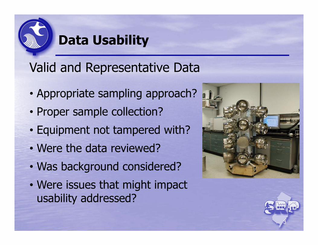
Data Usability
Valid and Representative Data
• Appropriate sampling approach?
• Proper sample collection?
• Equipment not tampered with?
• Were the data reviewed?
• Was background considered?
• Were issues that might impact usability addressed?
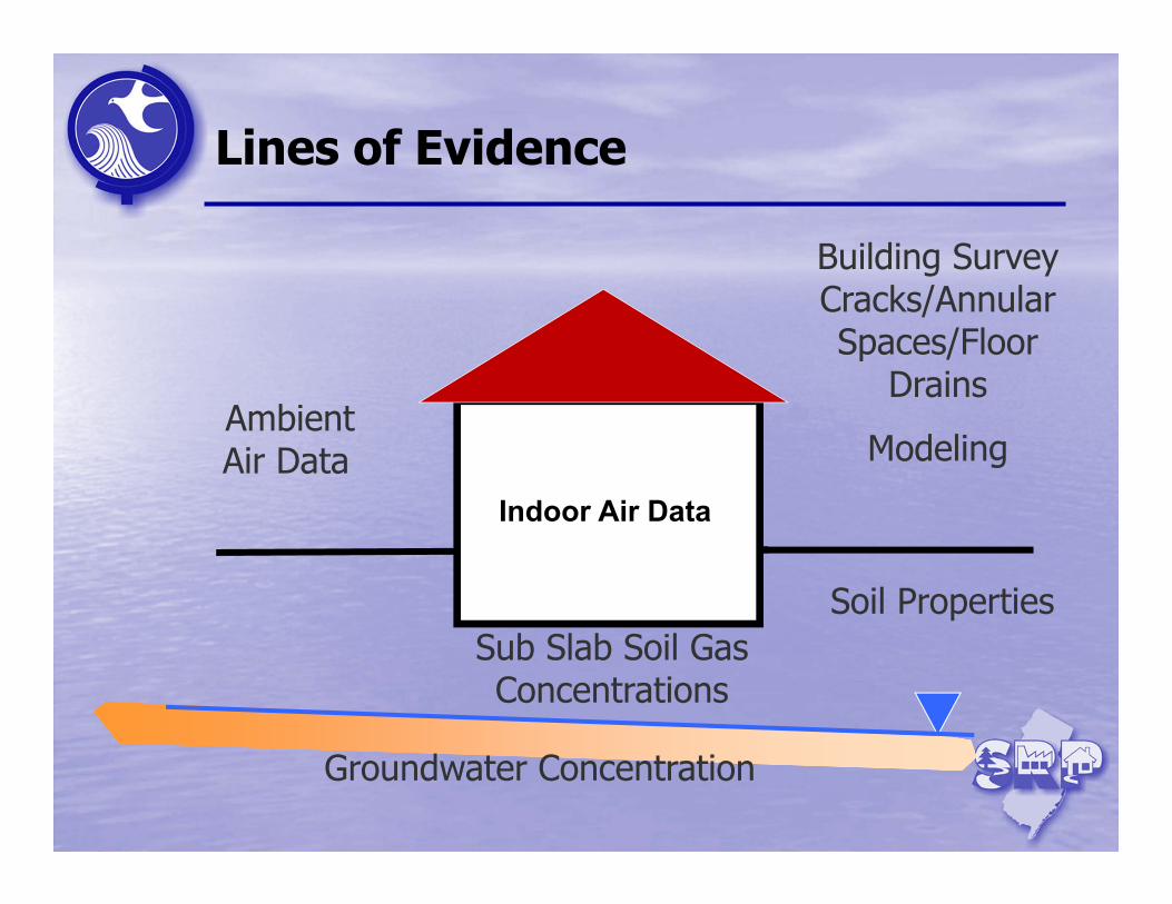
Groundwater Concentration
Sub Slab Soil Gas Concentrations
Indoor Air Data
Building Survey Cracks/Annular Spaces/Floor
Drains
ModelingAmbient Air Data
Lines of Evidence
Soil Properties
Multiple Lines of Evidence (MLE) Approach
Principle Concern: Is the VI Pathway from a Discharge to a Potentially Exposed Person Complete?
MLE Primary Factors:
• Indoor Air (and Background)• Groundwater Data• Site-Specific Contaminants of Concern• Sub Slab Soil Gas Samples• Ambient (outdoor) Air
Multiple Lines of Evidence (MLE) Approach
MLE Secondary Factors:
• Building Survey• Building Characteristics• Exterior Soil Gas Samples• Soil Properties• Modeling
Use these primary and secondary factors to refine your Conceptual Site Model
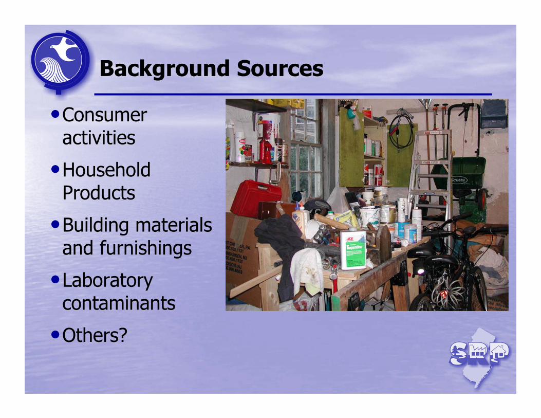
Background Sources
•Consumer activities
•Household Products
•Building materials and furnishings
•Laboratory contaminants
•Others?
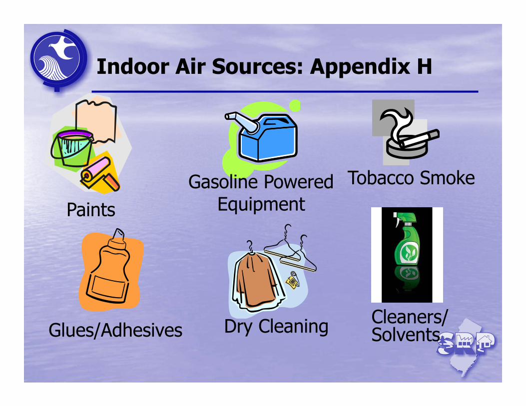
Indoor Air Sources: Appendix H
PaintsGasoline Powered
Equipment
Dry Cleaning
Tobacco Smoke
Glues/AdhesivesCleaners/Solvents
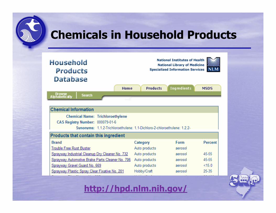
Chemicals in Household Products
http://hpd.nlm.nih.gov/
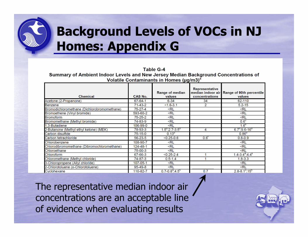
Background Levels of VOCs in NJ Homes: Appendix G
The representative median indoor air concentrations are an acceptable line of evidence when evaluating results
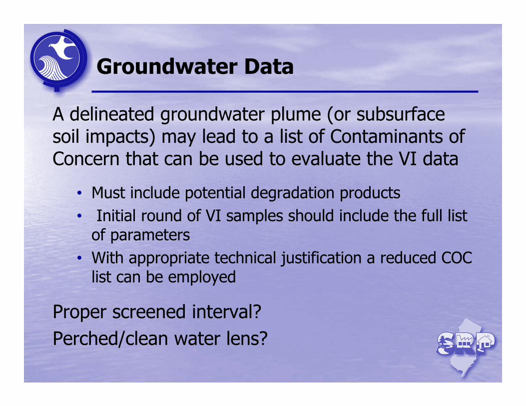
Groundwater Data
A delineated groundwater plume (or subsurface soil impacts) may lead to a list of Contaminants of Concern that can be used to evaluate the VI data
• Must include potential degradation products• Initial round of VI samples should include the full list
of parameters• With appropriate technical justification a reduced COC
list can be employed
Proper screened interval?Perched/clean water lens?
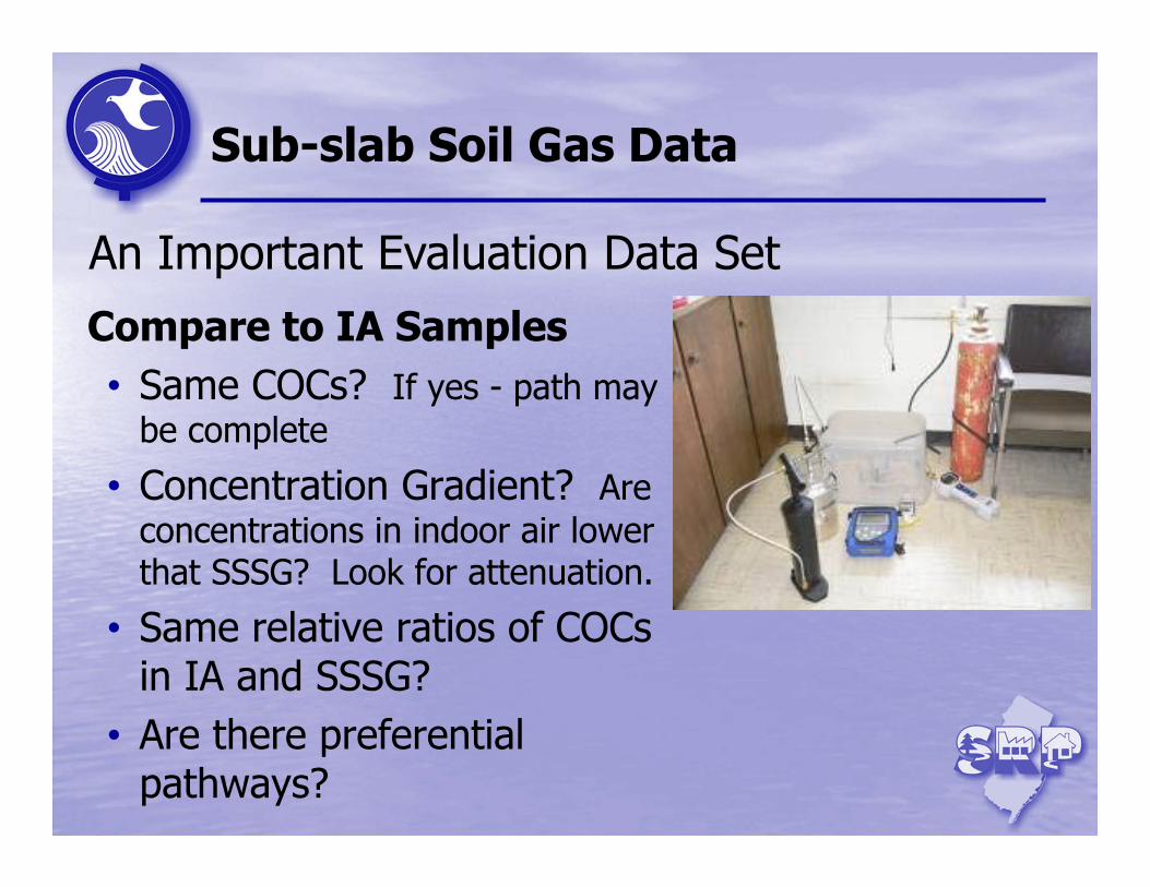
Sub-slab Soil Gas Data
Compare to IA Samples• Same COCs? If yes - path may
be complete
• Concentration Gradient? Are concentrations in indoor air lower that SSSG? Look for attenuation.
• Same relative ratios of COCs in IA and SSSG?
• Are there preferential pathways?
An Important Evaluation Data Set
Background Air Data
Ambient (Outdoor) Air SamplesCollect one sample during Indoor Air Sampling• Evaluate for potential impacts of indoor air from
outside air• Mitigation not required when Ambient > Indoor Air
Indoor Air BackgroundRefer to data available in Appendix G• Do not subtract background from IA data to
determine compliance
Building Characteristics
Review the Building Survey
• Potential Background Sources• Potential Preferential Pathways• HVAC and other building operational issues− Positive Air Pressure may minimize VI− Dirt Floors/Crawl Spaces− Ventilation Fans/Open doors− Sump pumps
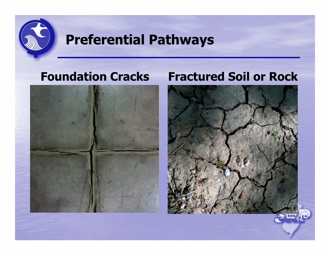
Preferential Pathways
Foundation Cracks Fractured Soil or Rock
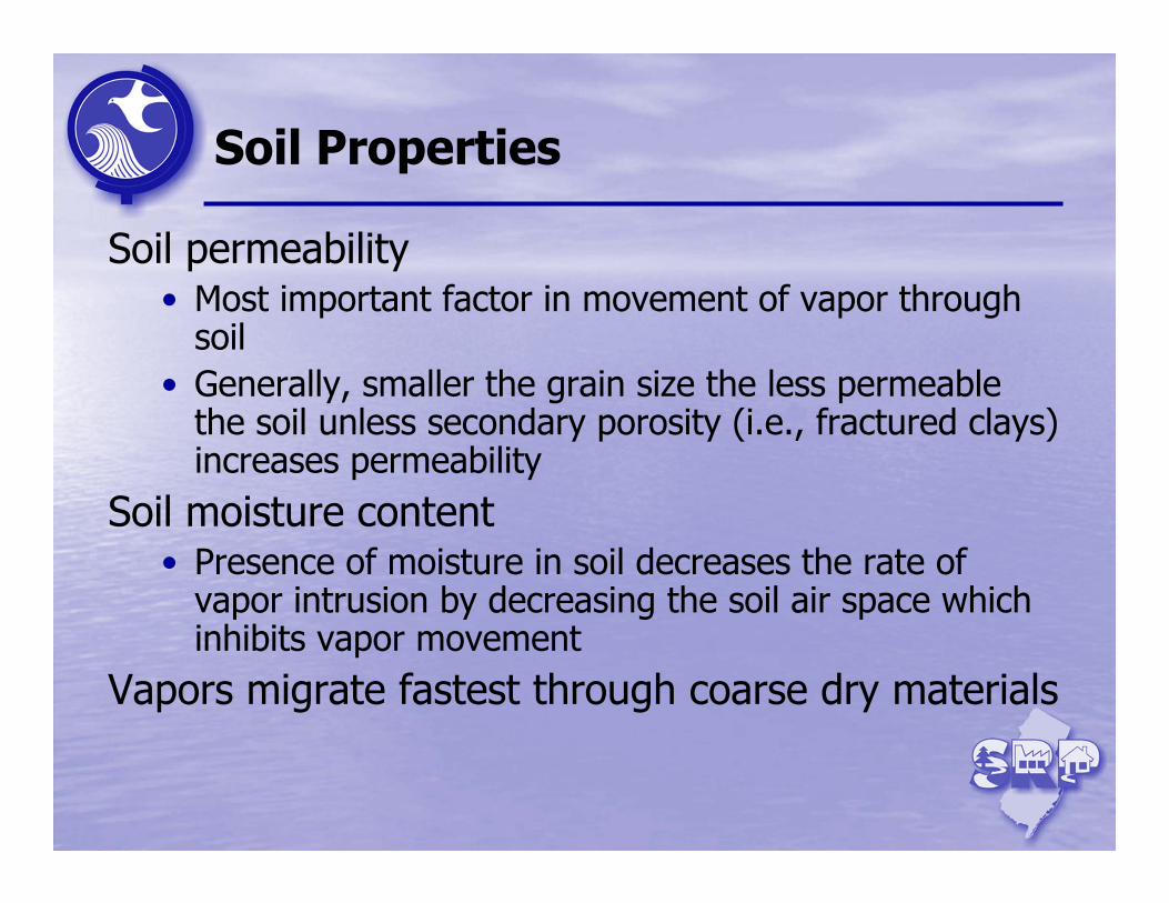
Soil Properties
Soil permeability• Most important factor in movement of vapor through
soil• Generally, smaller the grain size the less permeable
the soil unless secondary porosity (i.e., fractured clays) increases permeability
Soil moisture content• Presence of moisture in soil decreases the rate of
vapor intrusion by decreasing the soil air space which inhibits vapor movement
Vapors migrate fastest through coarse dry materials
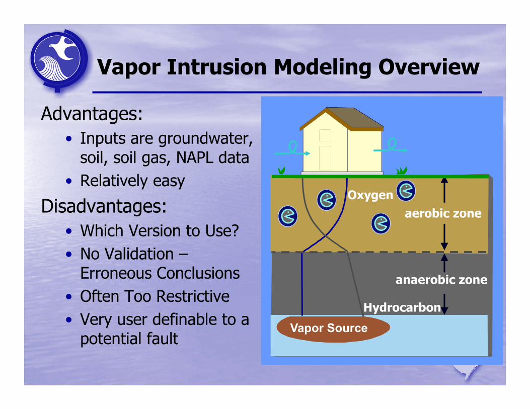
Vapor Intrusion Modeling Overview
Advantages:• Inputs are groundwater,
soil, soil gas, NAPL data• Relatively easy
Disadvantages:• Which Version to Use? • No Validation –
Erroneous Conclusions• Often Too Restrictive• Very user definable to a
potential faultVapor Source
Oxygenaerobic zone
anaerobic zone
Hydrocarbon
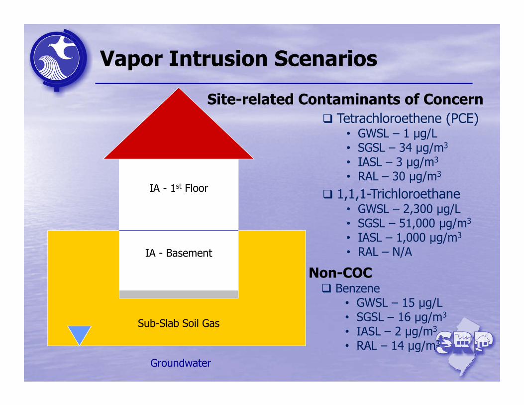
Vapor Intrusion Scenarios
Site-related Contaminants of Concern
IA - Basement
Sub-Slab Soil Gas
Groundwater
IA - 1st Floor
Tetrachloroethene (PCE)• GWSL – 1 µg/L• SGSL – 34 µg/m3
• IASL – 3 µg/m3
• RAL – 30 µg/m3
1,1,1-Trichloroethane • GWSL – 2,300 µg/L• SGSL – 51,000 µg/m3
• IASL – 1,000 µg/m3
• RAL – N/A
Non-COC Benzene
• GWSL – 15 µg/L• SGSL – 16 µg/m3
• IASL – 2 µg/m3
• RAL – 14 µg/m3

What Would the LSRP Do?
ISSUES:• IA COC > RAL• IA non-COC > IASL• SG & GW not
sampled• Status of VI Pathway
unknown
Benzene – 3 μg/m3
PCE – 35 μg/m3
SSSG not sampled
GW not sampled
Basement not sampled
ANSWER:
Investigate
Scenario #1
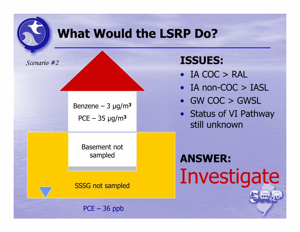
What Would the LSRP Do?
ISSUES:• IA COC > RAL• IA non-COC > IASL• GW COC > GWSL• Status of VI Pathway
still unknown
Benzene – 3 μg/m3
PCE – 35 μg/m3
SSSG not sampled
PCE – 36 ppb
Basement not sampled ANSWER:
Scenario #2
Investigate
What Would the LSRP Do?
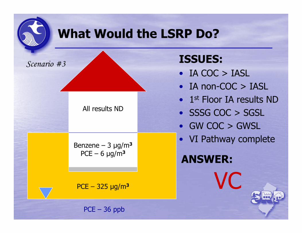
ISSUES:• IA COC > IASL• IA non-COC > IASL• 1st Floor IA results ND• SSSG COC > SGSL• GW COC > GWSL• VI Pathway complete
Benzene – 3 μg/m3
PCE – 6 μg/m3
PCE – 325 μg/m3
PCE – 36 ppb
All results ND
ANSWER:
VC
Scenario #3

What Would the LSRP Do?
ISSUES:• IA COC < IASL• IA non-COC > IASL• SSSG Non-COC > SGSL• GW Non-COC > GWSL• COCs well documented• VI Pathway complete
PCE – 1 μg/m3
Benzene – 6 μg/m3
PCE – 30 μg/m3
Benzene - 280 μg/m3
PCE – 4 μg/LBenzene – 45 μg/L
1st Floor not sampled
ANSWER:
VC, but . . .
Scenario #4
What Would the LSRP Do?
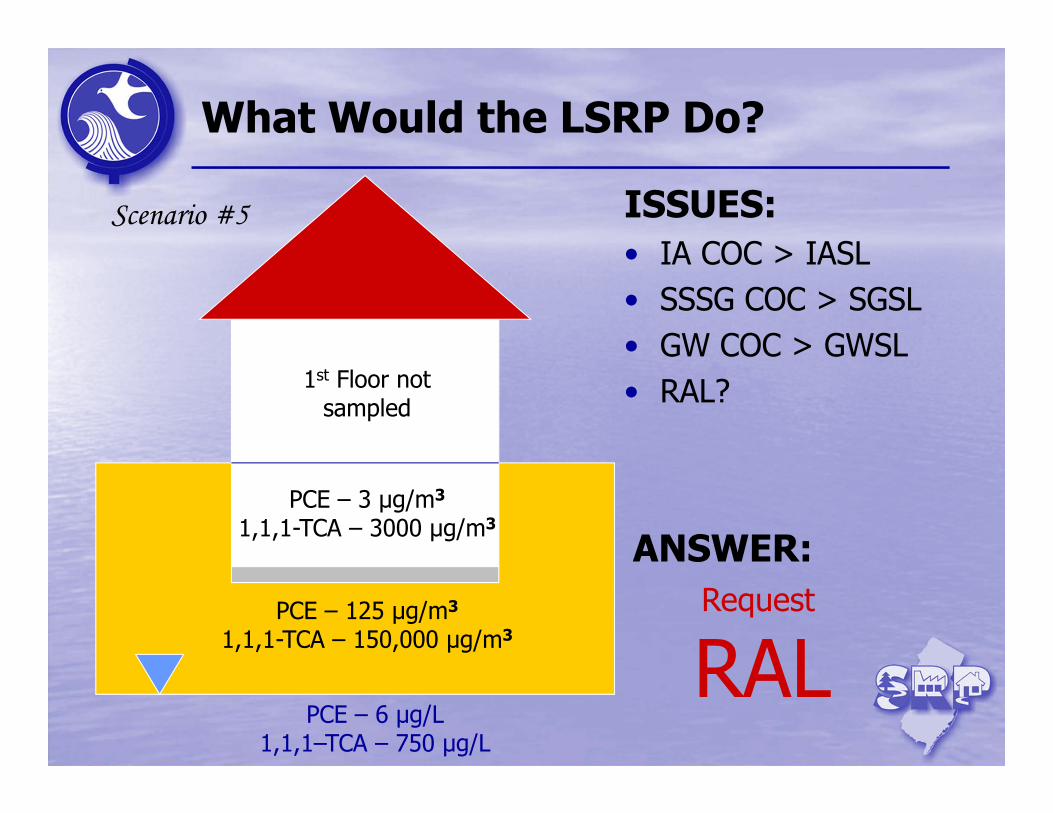
ISSUES:• IA COC > IASL• SSSG COC > SGSL• GW COC > GWSL • RAL?
PCE – 3 μg/m3
1,1,1-TCA – 3000 μg/m3
PCE – 125 μg/m3
1,1,1-TCA – 150,000 μg/m3
PCE – 6 μg/L1,1,1–TCA – 750 μg/L
ANSWER:Request
RAL
Scenario #5
1st Floor not sampled
What Would the LSRP Do?
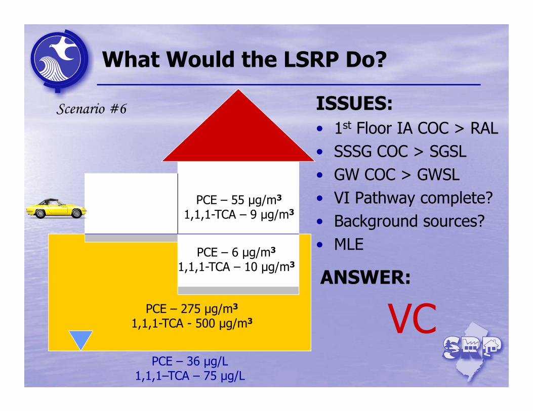
ISSUES:• 1st Floor IA COC > RAL• SSSG COC > SGSL• GW COC > GWSL • VI Pathway complete?• Background sources?• MLE
PCE – 55 μg/m3
1,1,1-TCA – 9 μg/m3
PCE – 275 μg/m3
1,1,1-TCA - 500 μg/m3
PCE – 36 μg/L1,1,1–TCA – 75 μg/L
ANSWER:
VC
PCE – 6 μg/m3
1,1,1-TCA – 10 μg/m3
Scenario #6
What Would the LSRP Do?
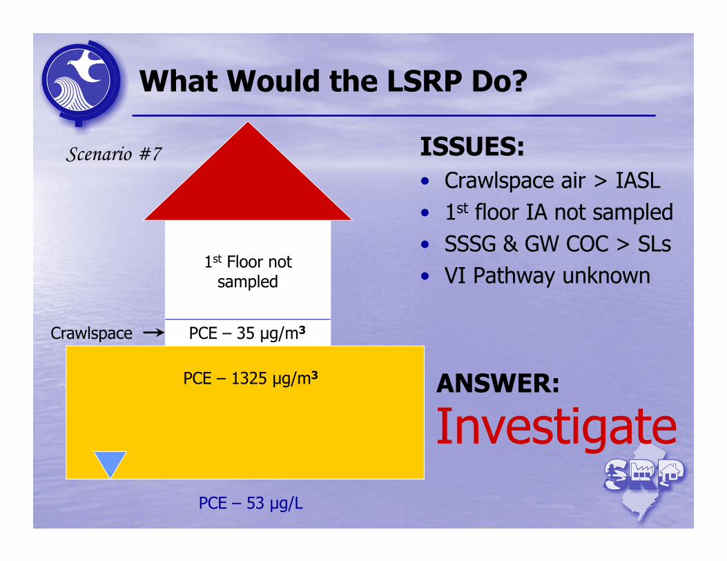
ISSUES:• Crawlspace air > IASL• 1st floor IA not sampled• SSSG & GW COC > SLs• VI Pathway unknown
PCE – 35 μg/m3
PCE – 1325 μg/m3
PCE – 53 μg/L
1st Floor not sampled
ANSWER:
Scenario #7
Crawlspace
Investigate
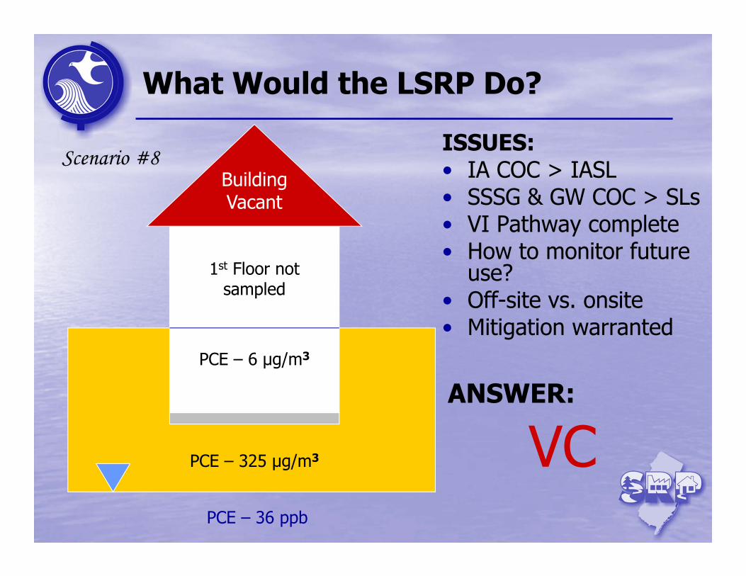
What Would the LSRP Do?
ISSUES:• IA COC > IASL• SSSG & GW COC > SLs• VI Pathway complete• How to monitor future
use?• Off-site vs. onsite• Mitigation warranted
PCE – 6 μg/m3
PCE – 325 μg/m3
PCE – 36 ppb
1st Floor not sampled
ANSWER:
VC
Building Vacant
Scenario #8
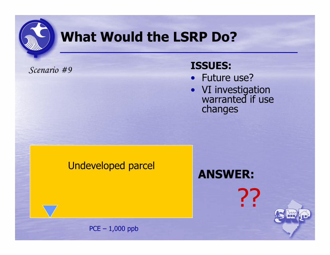
What Would the LSRP Do?
ISSUES:• Future use?• VI investigation
warranted if use changes
PCE – 1,000 ppb
ANSWER:
??
Scenario #9
Undeveloped parcel
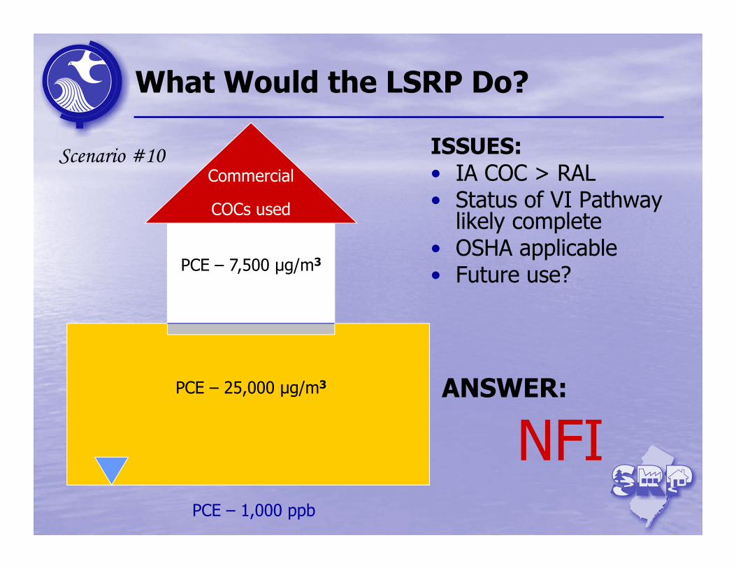
What Would the LSRP Do?
ISSUES:• IA COC > RAL• Status of VI Pathway
likely complete• OSHA applicable• Future use?PCE – 7,500 μg/m3
PCE – 25,000 μg/m3
PCE – 1,000 ppb
ANSWER:
NFI
CommercialScenario #10
COCs used
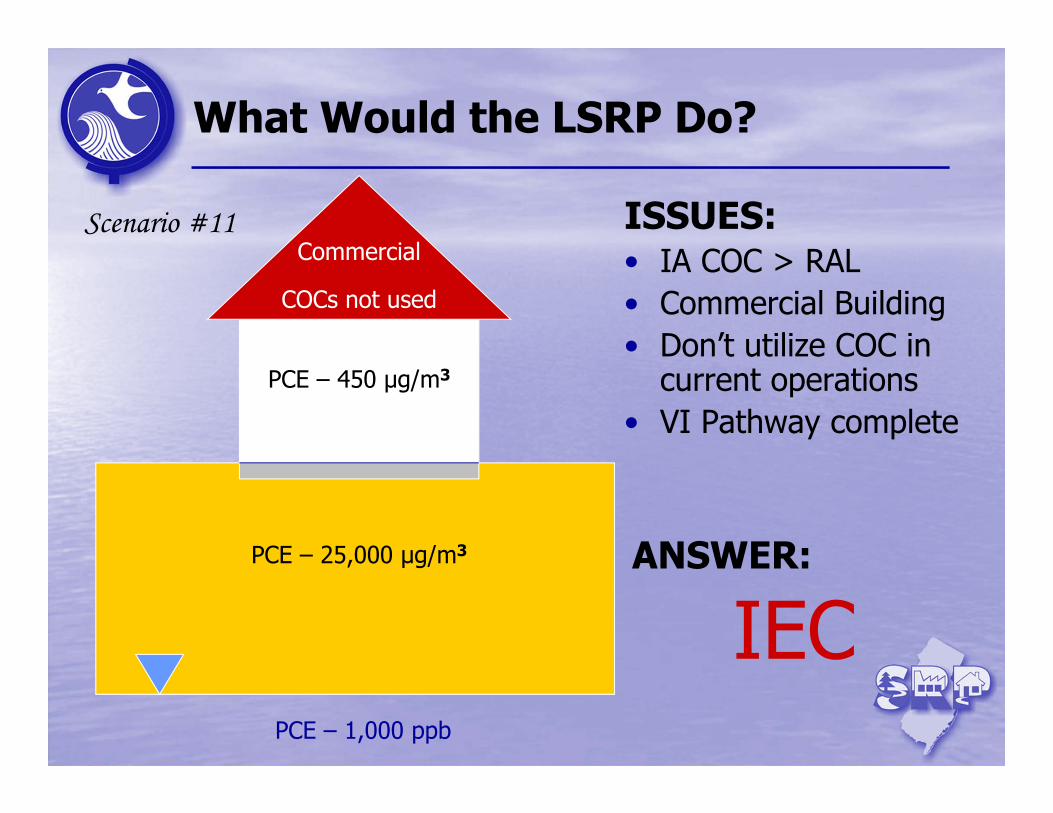
What Would the LSRP Do?
ISSUES:• IA COC > RAL• Commercial Building • Don’t utilize COC in
current operations• VI Pathway complete
PCE – 450 μg/m3
PCE – 25,000 μg/m3
PCE – 1,000 ppb
ANSWER:
IEC
CommercialScenario #11
COCs not used
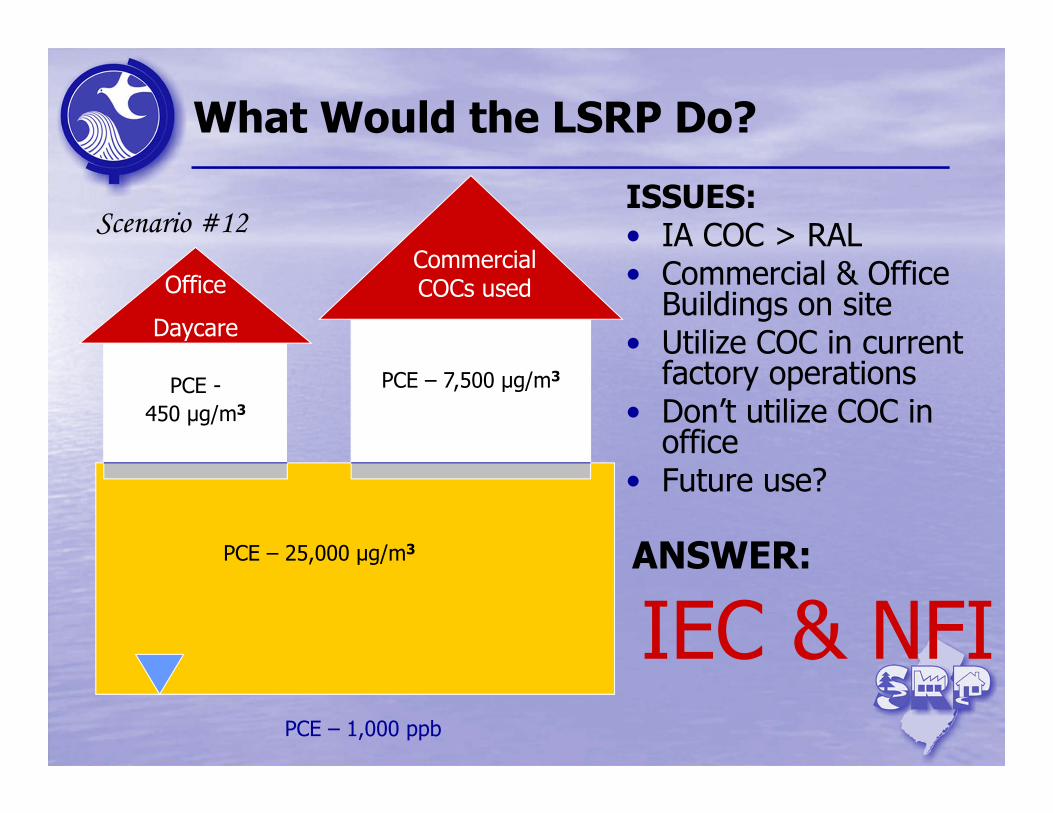
What Would the LSRP Do?
ISSUES:• IA COC > RAL• Commercial & Office
Buildings on site • Utilize COC in current
factory operations• Don’t utilize COC in
office• Future use?
PCE – 7,500 μg/m3
PCE – 25,000 μg/m3
PCE – 1,000 ppb
ANSWER:
IEC
CommercialCOCs usedOffice
Daycare
PCE -450 μg/m3
Scenario #12
& NFI
31
Petroleum Hydrocarbons
Introduction
VI Investigation (Stage 2)
VI Receptor Evaluation(Stage 1)
VI Framework
Break
PetroleumHydrocarbons
MLE & Data Evaluation
Mitigation (Stage 3)
OMM (Stage 4) & Termination (Stage 5)
32
Petroleum Hydrocarbons
Petroleum Hydrocarbons of interest to VI include:• gasoline, diesel fuel, No.2 Heating Oil, Kerosene, and
aviation fuels.
VI critical distance criteria (N.J.A.C.7:26E-1.18):• Free product located or suspected within 100 feet of
a building• Petroleum-related compounds in groundwater in
excess of the GWSL within 30 feet of a building
Gasoline discharges represent a significant portion of the petroleum–related VI investigations in New Jersey.
33
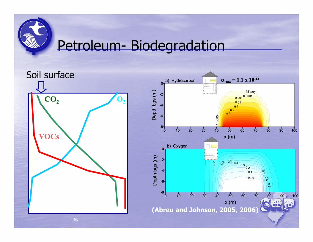
Petroleum- Biodegradation
Research over the last decade has demonstrated that petroleum-related compounds can biodegrade in the vadose zone.
General requirements include:• Microorganisms• Oxygen• Nutrients• Moisture
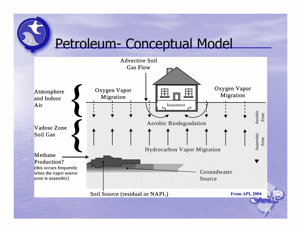
Petroleum- Conceptual Model
34
Atmosphereand IndoorAir
Groundwater Source
Vadose ZoneSoil Gas {
Soil Source (residual or NAPL)
Hydrocarbon Vapor Migration
basement{ Oxygen VaporMigration
Oxygen VaporMigration
Aerobic Biodegradation
MethaneProduction?(this occurs frequentlywhen the vapor sourcezone is anaerobic)
Advective SoilGas Flow
Ana
erob
icZo
neA
erob
icZo
ne
From API, 2004
Petroleum- Biodegradation
35
0 10 20 30 40 50 60 70 80 90 100
x (m)
-8
-6
-4
-2
0
Dep
th b
gs (m
)
0 10 20 30 40 50 60 70 80 90 100
x (m)
-8
-6
-4
-2
0
Dep
th b
gs (m
)
a) Hydrocarbon
b) Oxygen
bio = 1.1 x 10⁻¹³
0 10 20 30 40 50 60 70 80 90 100
x (m)
-8
-6
-4
-2
0
Dep
th b
gs (m
)
0 10 20 30 40 50 60 70 80 90 100
x (m)
-8
-6
-4
-2
0
Dep
th b
gs (m
)
a) Hydrocarbon
b) Oxygen
bio = 1.1 x 10⁻¹³
(Abreu and Johnson, 2005, 2006)
Soil surface
CO2
VOCs
O2
36
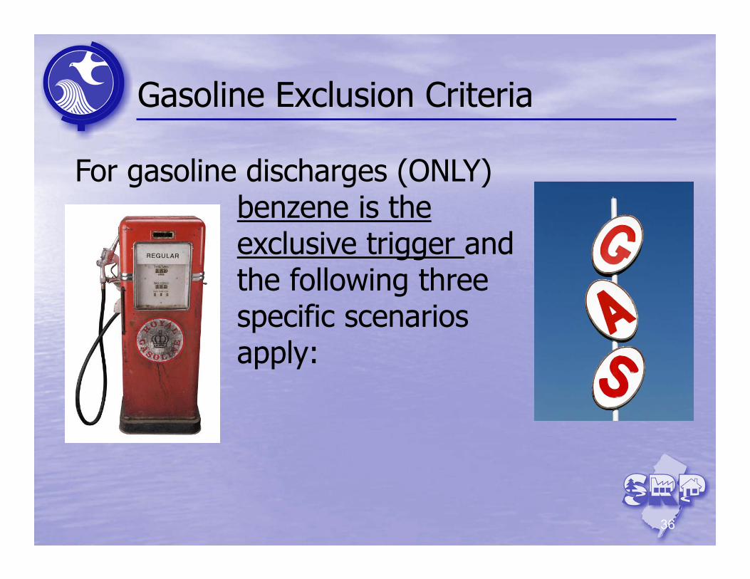
Gasoline Exclusion Criteria
For gasoline discharges (ONLY) benzene is the exclusive trigger and the following three specific scenarios apply:
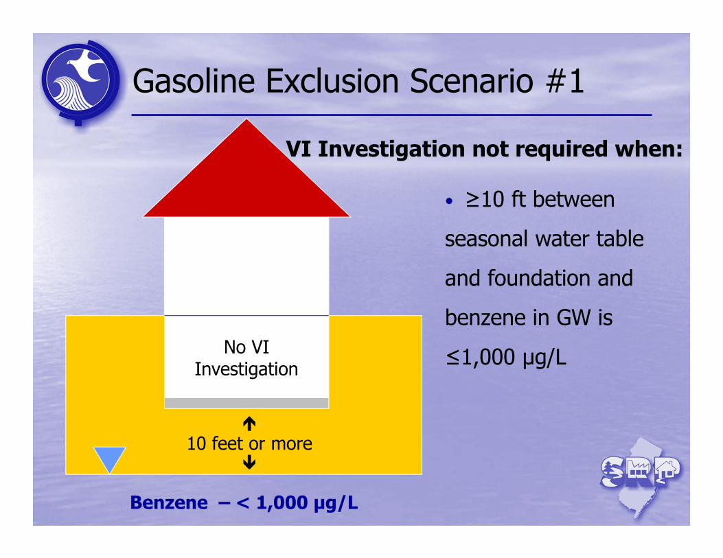
Gasoline Exclusion Scenario #1
PCE – 325 μg/m3 •
Benzene – < 1,000 μg/L
No VI Investigation
• ≥10 ft between
seasonal water table
and foundation and
benzene in GW is
≤1,000 μg/L
VI Investigation not required when:
10 feet or more
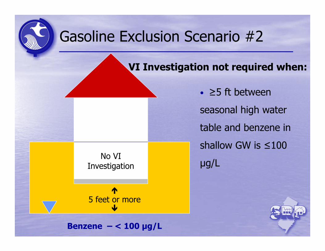
Gasoline Exclusion Scenario #2
PCE – 325 μg/m3 •
Benzene – < 100 μg/L
No VI Investigation
• ≥5 ft between
seasonal high water
table and benzene in
shallow GW is ≤100
μg/L
VI Investigation not required when:
5 feet or more
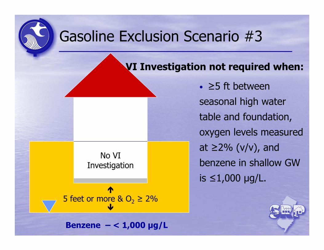
Gasoline Exclusion Scenario #3
PCE – 325 μg/m3 •
Benzene – < 1,000 μg/L
No VI Investigation
• ≥5 ft between
seasonal high water
table and foundation,
oxygen levels measured
at ≥2% (v/v), and
benzene in shallow GW
is ≤1,000 μg/L.
VI Investigation not required when:
5 feet or more & O2 ≥ 2%
40
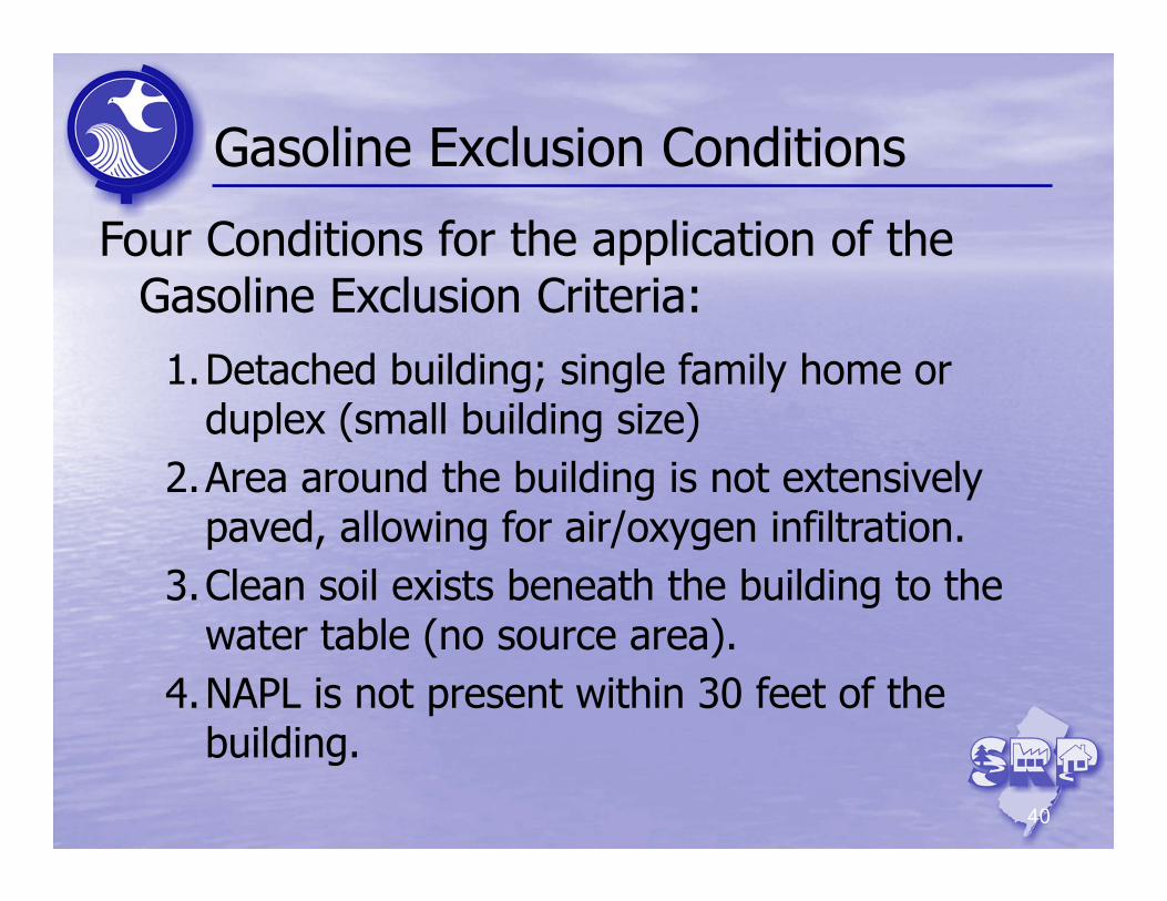
Gasoline Exclusion Conditions
Four Conditions for the application of the Gasoline Exclusion Criteria:
1.Detached building; single family home or duplex (small building size)
2.Area around the building is not extensively paved, allowing for air/oxygen infiltration.
3.Clean soil exists beneath the building to the water table (no source area).
4.NAPL is not present within 30 feet of the building.
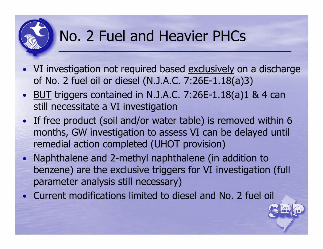
No. 2 Fuel and Heavier PHCs
• VI investigation not required based exclusively on a discharge of No. 2 fuel oil or diesel (N.J.A.C. 7:26E-1.18(a)3)
• BUT triggers contained in N.J.A.C. 7:26E-1.18(a)1 & 4 can still necessitate a VI investigation
• If free product (soil and/or water table) is removed within 6 months, GW investigation to assess VI can be delayed until remedial action completed (UHOT provision)
• Naphthalene and 2-methyl naphthalene (in addition to benzene) are the exclusive triggers for VI investigation (full parameter analysis still necessary)
• Current modifications limited to diesel and No. 2 fuel oil
42
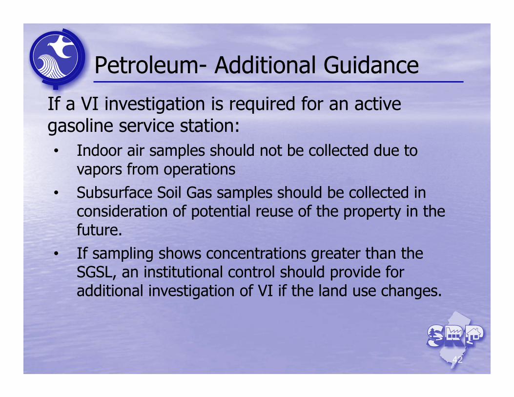
Petroleum- Additional Guidance
If a VI investigation is required for an active gasoline service station:• Indoor air samples should not be collected due to
vapors from operations• Subsurface Soil Gas samples should be collected in
consideration of potential reuse of the property in the future.
• If sampling shows concentrations greater than the SGSL, an institutional control should provide for additional investigation of VI if the land use changes.
43
Vapor Intrusion Mitigation (Stage 3)
Introduction
VI Investigation (Stage 2)
VI Receptor Evaluation(Stage 1)
VI Framework
Break
PetroleumHydrocarbons
MLE & Data Evaluation
Mitigation (Stage 3)
OMM (Stage 4) & Termination (Stage 5)
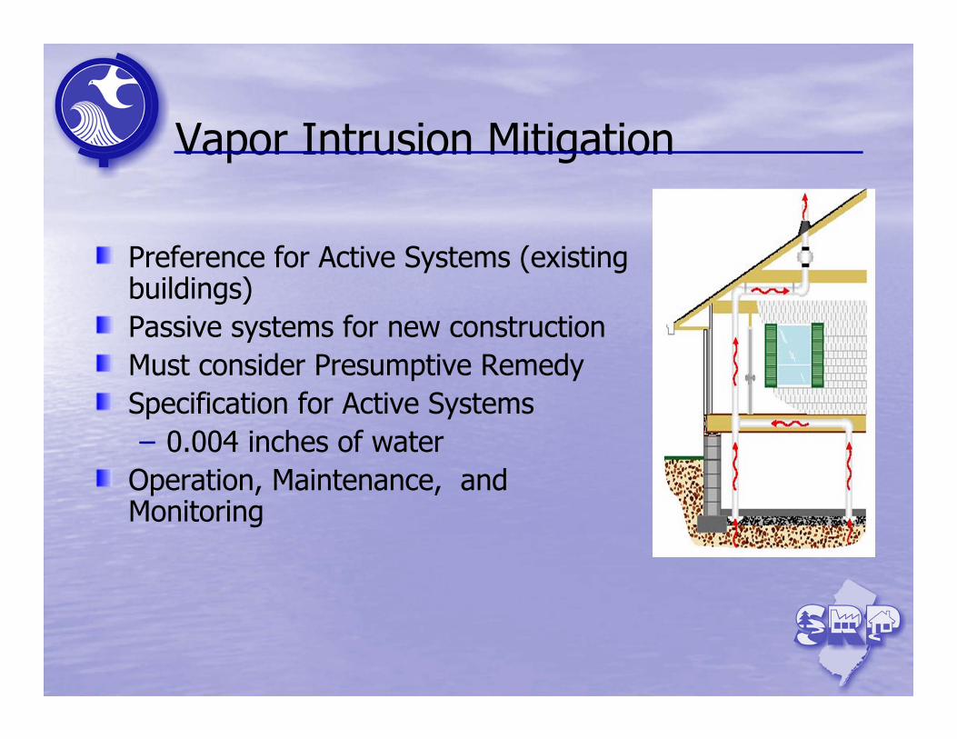
Vapor Intrusion Mitigation
Preference for Active Systems (existing buildings)Passive systems for new constructionMust consider Presumptive RemedySpecification for Active Systems– 0.004 inches of water
Operation, Maintenance, and Monitoring
45
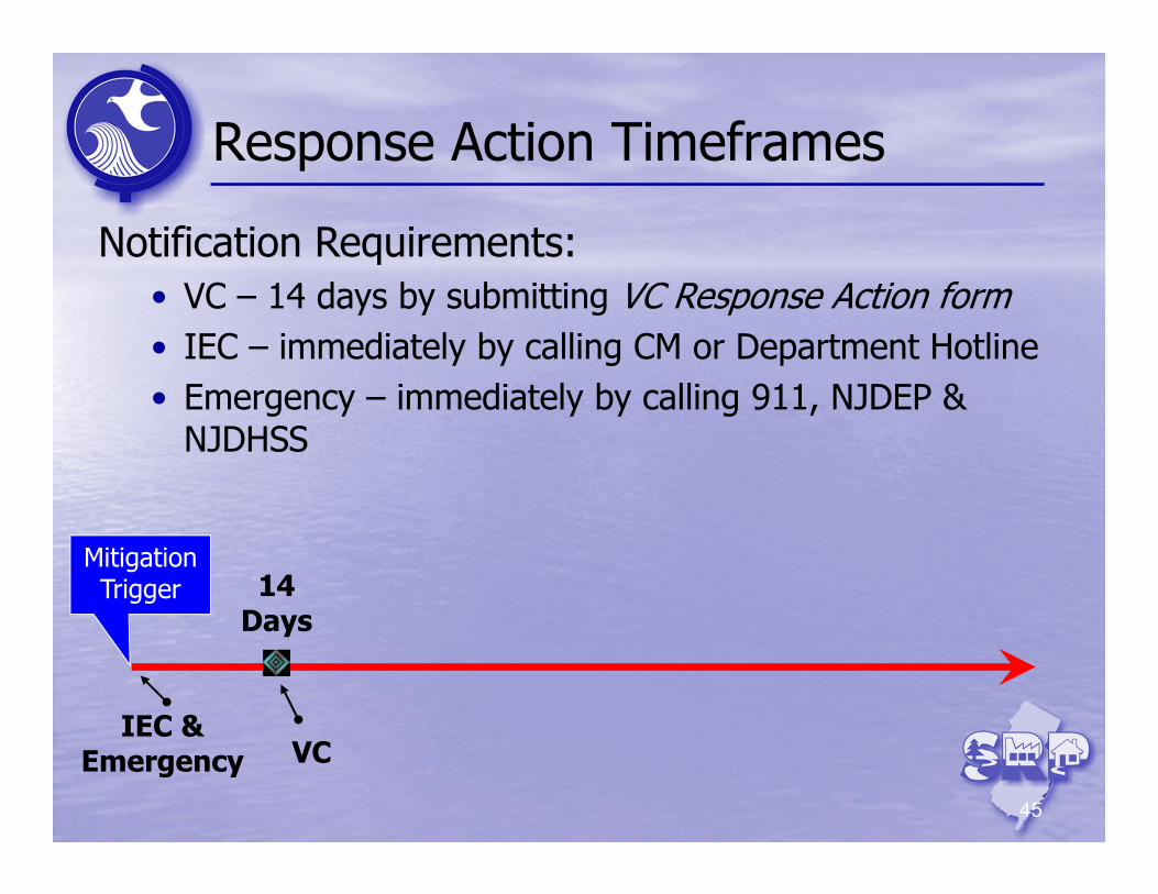
Response Action Timeframes
Mitigation Trigger 14
Days
IEC & Emergency VC
Notification Requirements:• VC – 14 days by submitting VC Response Action form• IEC – immediately by calling CM or Department Hotline• Emergency – immediately by calling 911, NJDEP &
NJDHSS
46
Response Action Timeframes
MitigationTrigger 14
Days
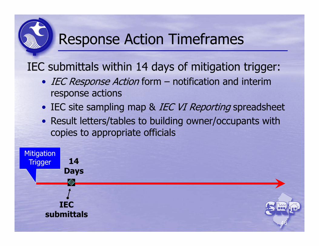
IEC submittals
IEC submittals within 14 days of mitigation trigger:• IEC Response Action form – notification and interim
response actions• IEC site sampling map & IEC VI Reporting spreadsheet• Result letters/tables to building owner/occupants with
copies to appropriate officials
47
Engineered System Response Action
Mitigation Trigger
Implement Plan
Submit Report
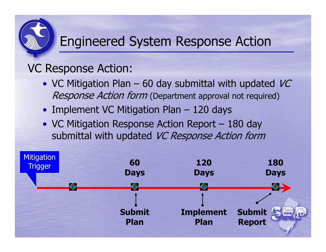
VC Response Action:• VC Mitigation Plan – 60 day submittal with updated VC
Response Action form (Department approval not required)
• Implement VC Mitigation Plan – 120 days• VC Mitigation Response Action Report – 180 day
submittal with updated VC Response Action form
60 Days
120 Days
180 Days
Submit Plan
48
Engineered System Response Action
Mitigation Trigger
Implement ESRA
Submit Report
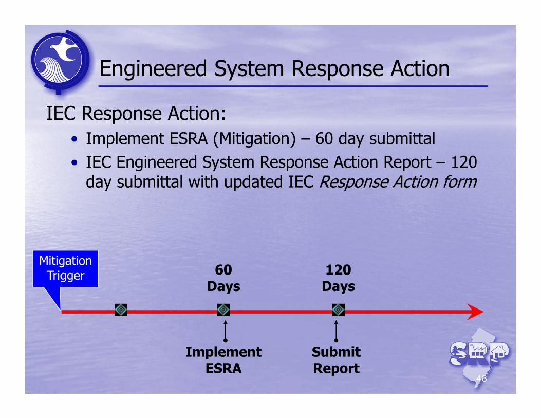
IEC Response Action:• Implement ESRA (Mitigation) – 60 day submittal • IEC Engineered System Response Action Report – 120
day submittal with updated IEC Response Action form
60 Days
120 Days
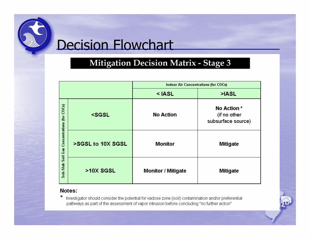
Decision Flowchart
Interim Response Actions
50
• Sealing major openings and cracks• Repairing compromised areas of the slab• Covering and sealing exposed earth• Covering and sealing sump pits• Utilizing carbon IA filtration fan units• Implementing selective or natural ventilation• Adjusting HVAC settings (e.g., positive
pressure, balance)• Limiting access to building or area of interest• Evacuating occupants
Initial mitigation steps conducted to protect receptors within 14 days of the IEC trigger
51
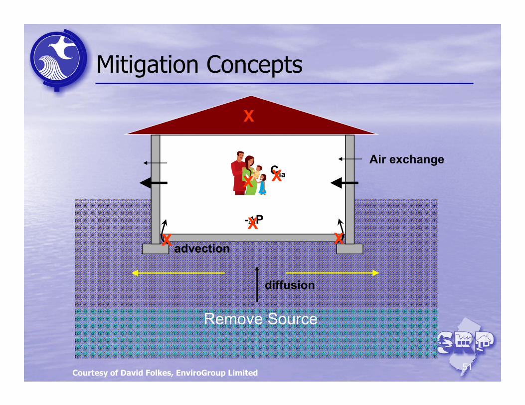
Mitigation Concepts
diffusion
advection
Air exchangeCia
-∆P
Remove Source
X
X XX
XX
Courtesy of David Folkes, EnviroGroup Limited
52
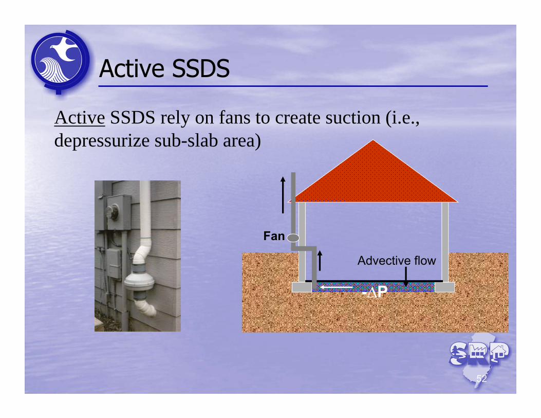
Active SSDS
-∆P
Advective flow
Fan
Active SSDS rely on fans to create suction (i.e., depressurize sub-slab area)
53
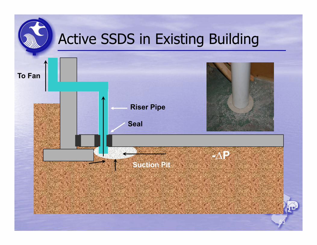
Active SSDS in Existing Building
Riser Pipe
To Fan
Seal
Suction Pit-∆P
54
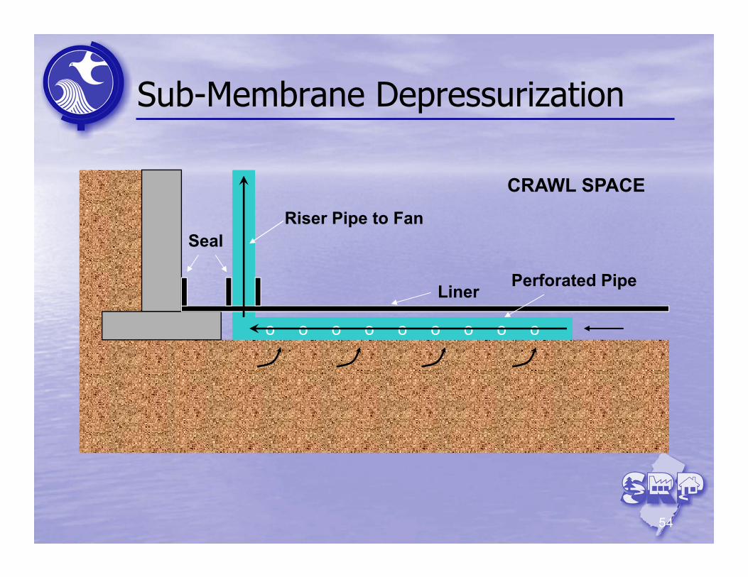
Sub-Membrane Depressurization
Riser Pipe to Fan
Liner
Seal
o o o o o o o o o
Perforated Pipe
CRAWL SPACE
55
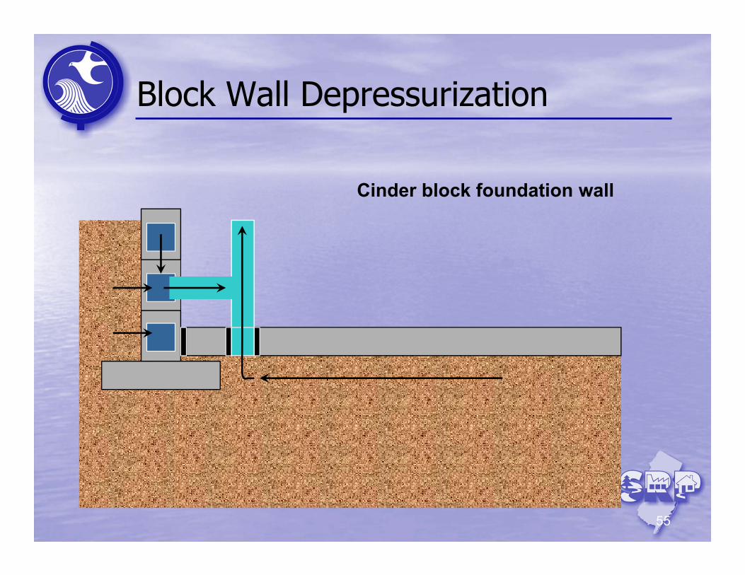
Block Wall Depressurization
Cinder block foundation wall
56
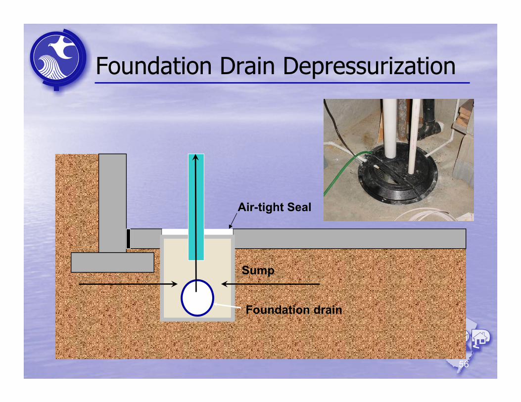
Foundation Drain Depressurization
Foundation drain
Sump
Air-tight Seal
57
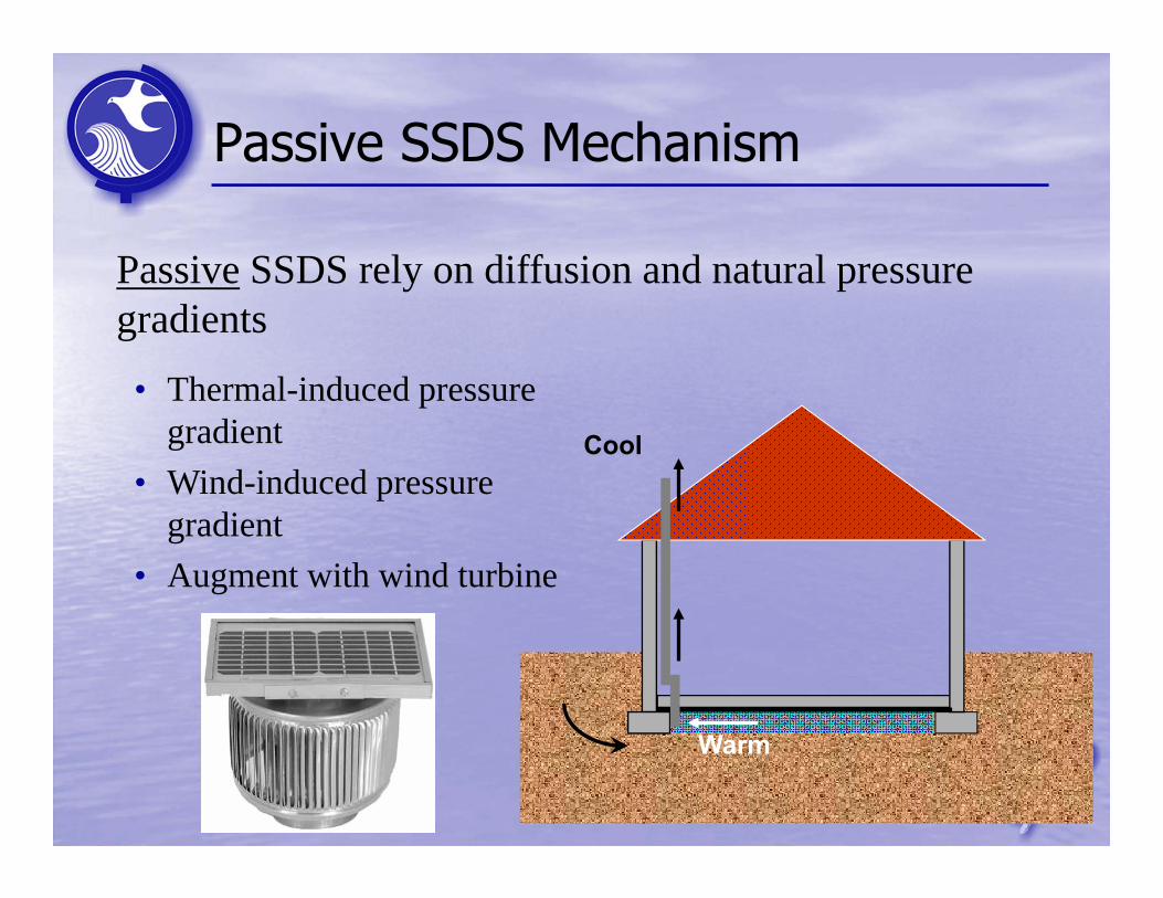
Passive SSDS Mechanism
Cool
Warm
• Thermal-induced pressure gradient
• Wind-induced pressure gradient
• Augment with wind turbine
Passive SSDS rely on diffusion and natural pressure gradients
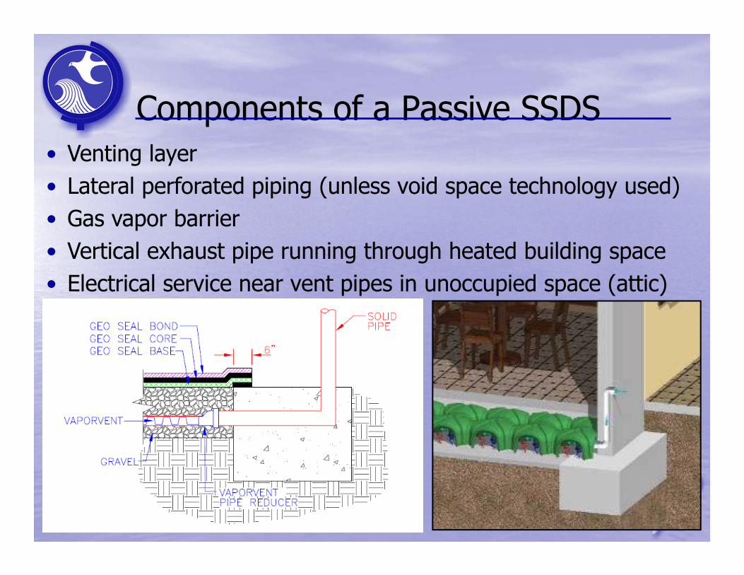
Components of a Passive SSDS
58
• Venting layer• Lateral perforated piping (unless void space technology used)• Gas vapor barrier • Vertical exhaust pipe running through heated building space• Electrical service near vent pipes in unoccupied space (attic)
59
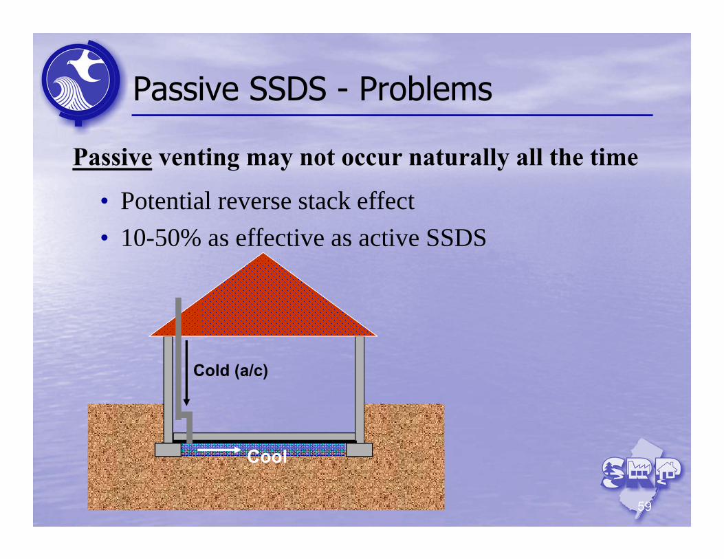
Passive SSDS - Problems
Cold (a/c)
Cool
Passive venting may not occur naturally all the time
• Potential reverse stack effect• 10-50% as effective as active SSDS
60
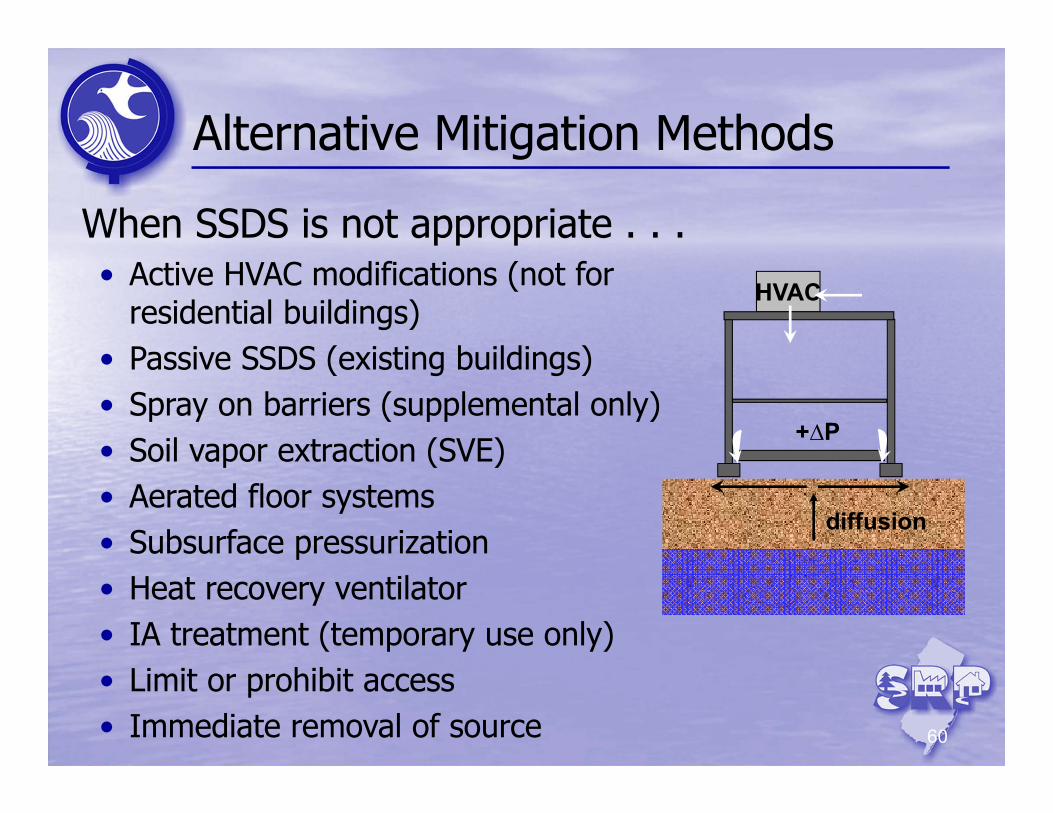
Alternative Mitigation Methods
HVAC
diffusion
+∆P
When SSDS is not appropriate . . .• Active HVAC modifications (not for
residential buildings)• Passive SSDS (existing buildings)• Spray on barriers (supplemental only)• Soil vapor extraction (SVE)• Aerated floor systems• Subsurface pressurization• Heat recovery ventilator• IA treatment (temporary use only)• Limit or prohibit access• Immediate removal of source
61
Design & Installer Qualifications
For design & installation of a vapor mitigation system, utilize:
• NJ Certified Radon Mitigation Contractor• Licensed Site Remediation Professional *• Licensed Professional Engineer ** with specific experience in VI or radon building mitigation
Don’t forget local building codes Licensed electrician will be needed Asbestos materials may be present
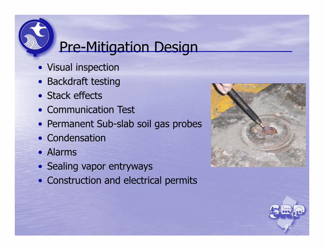
Pre-Mitigation Design
62
• Visual inspection• Backdraft testing• Stack effects• Communication Test• Permanent Sub-slab soil gas probes• Condensation• Alarms• Sealing vapor entryways• Construction and electrical permits

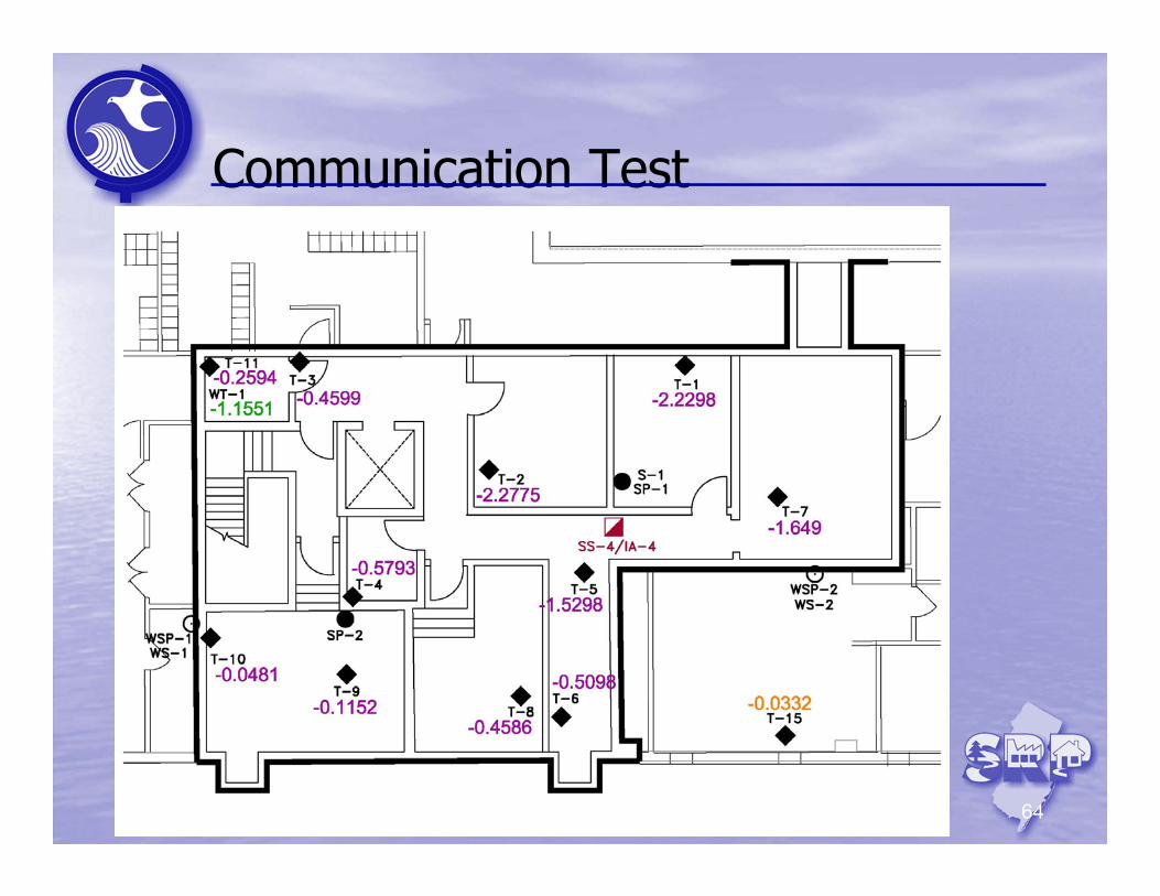
Communication Test
63
Critical step in proper design of active SSDS • Extent of depressurization field (suction) under slab• Determines the number and locations of suction point(s)
and fan size(s)• Minimum 0.004 inches water column (wc)
Slab
∆P = Pss – Pbuilding
Pss
Pbuilding
Negative ∆P
Positive ∆P
Communication Test
64
65
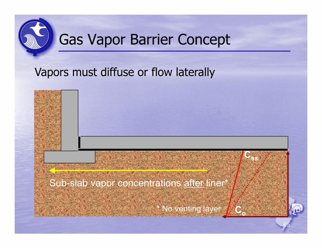
Gas Vapor Barrier Concept
Vapors must diffuse or flow laterally
Co
Css
Sub-slab vapor concentrations after liner*
* No venting layer
66
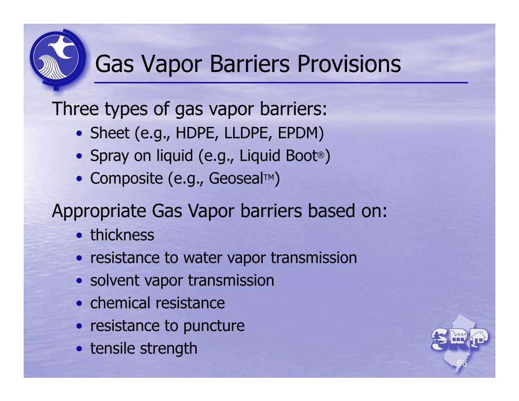
Gas Vapor Barriers Provisions
Three types of gas vapor barriers:• Sheet (e.g., HDPE, LLDPE, EPDM)• Spray on liquid (e.g., Liquid Boot®)• Composite (e.g., GeosealTM)
Appropriate Gas Vapor barriers based on:• thickness• resistance to water vapor transmission• solvent vapor transmission• chemical resistance• resistance to puncture• tensile strength
67
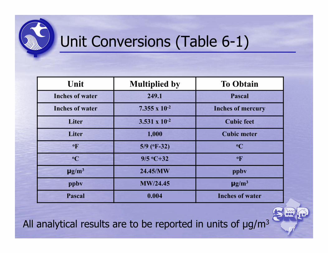
Unit Conversions (Table 6-1)
Unit Multiplied by To ObtainInches of water 249.1 Pascal
Inches of water 7.355 x 10⁻² Inches of mercury
Liter 3.531 x 10⁻² Cubic feet
Liter 1,000 Cubic meteroF 5/9 (oF-32) oCoC 9/5 oC+32 oF
µg/m3 24.45/MW ppbv
ppbv MW/24.45 µg/m3
Pascal 0.004 Inches of water
All analytical results are to be reported in units of μg/m3
System Commissioning
68
• Visual inspection of mitigation system• Comparison to Vapor Intrusion Mitigation System
Inspection Checklist (Appendix M)• Establishment of operational baseline from appropriate
system diagnostic parameters based on type of vapor mitigation system
• System assessment for alterations or augmentations• Trouble-shoot any problems (noise, vibration,
complaints)• Backdraft testing• Explanation of system components to building
owner/occupant
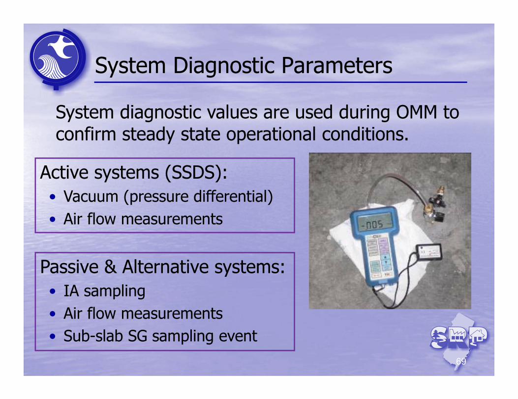
System Diagnostic Parameters
69
Active systems (SSDS):• Vacuum (pressure differential)• Air flow measurements
System diagnostic values are used during OMM to confirm steady state operational conditions.
Passive & Alternative systems:• IA sampling• Air flow measurements• Sub-slab SG sampling event
Verification Sampling (VS)
70
• Collect indoor and ambient air samples to verify the effectiveness of the vapor mitigation system
• Samples collected immediately following system commissioning (usually 30-45 days after system start-up)
• Minimum of one round of sampling during the heating season
• VS samples collected irrespective of the vapor mitigation system installed
• Background sources of COCs can complicate review of VS results
• Always use MLE when assessing system effectiveness
71
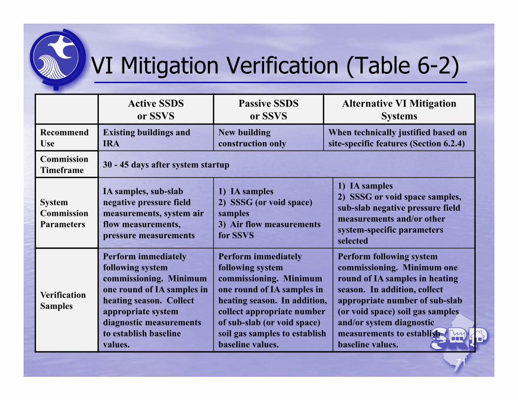
VI Mitigation Verification (Table 6-2)Active SSDS
or SSVSPassive SSDS
or SSVSAlternative VI Mitigation
SystemsRecommend Use
Existing buildings and IRA
New building construction only
When technically justified based on site-specific features (Section 6.2.4)
Commission Timeframe 30 - 45 days after system startup
System Commission Parameters
IA samples, sub-slab negative pressure field measurements, system air flow measurements, pressure measurements
1) IA samples 2) SSSG (or void space) samples3) Air flow measurements for SSVS
1) IA samples 2) SSSG or void space samples, sub-slab negative pressure field measurements and/or other system-specific parameters selected
Verification Samples
Perform immediately following system commissioning. Minimum one round of IA samples in heating season. Collect appropriate system diagnostic measurements to establish baseline values.
Perform immediately following system commissioning. Minimum one round of IA samples in heating season. In addition, collect appropriate number of sub-slab (or void space) soil gas samples to establish baseline values.
Perform following system commissioning. Minimum one round of IA samples in heating season. In addition, collect appropriate number of sub-slab (or void space) soil gas samples and/or system diagnostic measurements to establish baseline values.
72
OMM & Termination (Stages 4 & 5)
Introduction
VI Investigation (Stage 2)
VI Receptor Evaluation(Stage 1)
VI Framework
Break
PetroleumHydrocarbons
MLE & Data Evaluation
Mitigation (Stage 3)
OMM (Stage 4) & Termination (Stage 5)
73
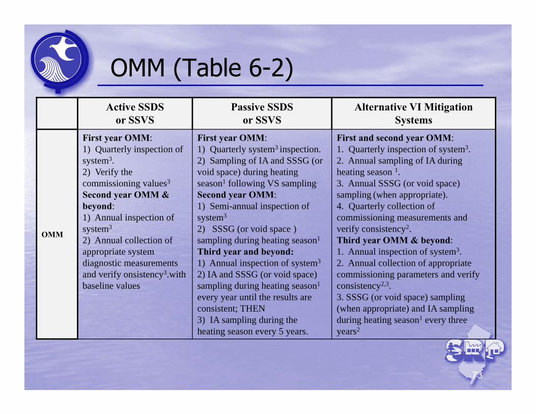
OMM (Table 6-2)Active SSDS
or SSVSPassive SSDS
or SSVSAlternative VI Mitigation
Systems
OMM
First year OMM:1) Quarterly inspection of system3. 2) Verify the commissioning values3
Second year OMM & beyond:1) Annual inspection of system3
2) Annual collection of appropriate system diagnostic measurements and verify onsistency3.with baseline values
First year OMM:1) Quarterly system3 inspection. 2) Sampling of IA and SSSG (or void space) during heating season1 following VS sampling.
Second year OMM:1) Semi-annual inspection of system3
2) SSSG (or void space ) sampling during heating season1
Third year and beyond:1) Annual inspection of system3
2) IA and SSSG (or void space) sampling during heating season1
every year until the results are consistent; THEN3) IA sampling during the heating season every 5 years.
First and second year OMM:1. Quarterly inspection of system3. 2. Annual sampling of IA during heating season 1. 3. Annual SSSG (or void space) sampling (when appropriate).4. Quarterly collection of commissioning measurements and verify consistency2.Third year OMM & beyond:1. Annual inspection of system3.2. Annual collection of appropriate commissioning parameters and verify consistency2,3.3. SSSG (or void space) sampling (when appropriate) and IA sampling during heating season1 every three years2
74
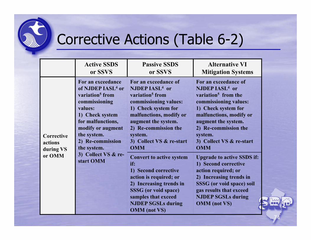
Corrective Actions (Table 6-2)
Active SSDSor SSVS
Passive SSDSor SSVS
Alternative VI Mitigation Systems
Corrective actions during VS or OMM
For an exceedance of NJDEP IASL4 or variation5 from commissioning values:1) Check system for malfunctions, modify or augment the system.2) Re-commission the system.3) Collect VS & re-start OMM
For an exceedance of NJDEP IASL4 or variation5 from commissioning values:1) Check system for malfunctions, modify or augment the system.2) Re-commission the system.3) Collect VS & re-start OMM
For an exceedance of NJDEP IASL4 or variation5 from the commissioning values:1) Check system for malfunctions, modify or augment the system.2) Re-commission the system.3) Collect VS & re-start OMM
Convert to active system if:1) Second corrective action is required; or2) Increasing trends in SSSG (or void space) samples that exceed NJDEP SGSLs during OMM (not VS)
Upgrade to active SSDS if:1) Second corrective action required; or2) Increasing trends in SSSG (or void space) soil gas results that exceed NJDEP SGSLs during OMM (not VS)
75
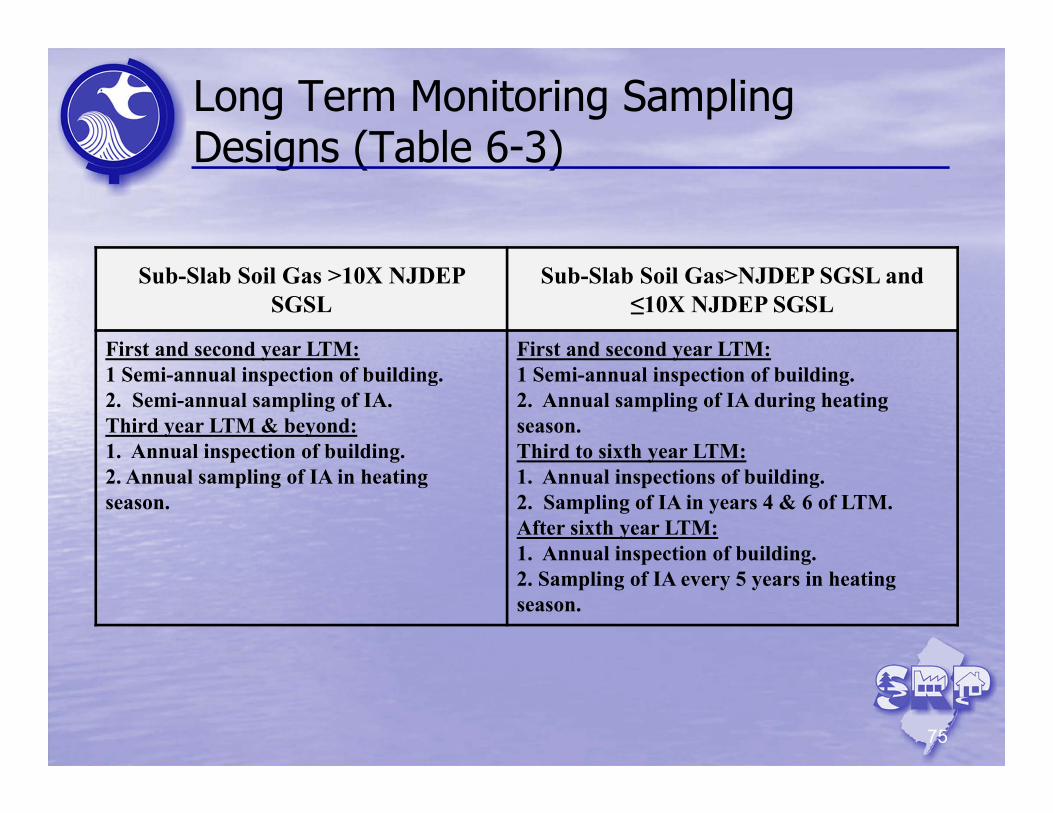
Long Term Monitoring Sampling Designs (Table 6-3)
Sub-Slab Soil Gas >10X NJDEP SGSL
Sub-Slab Soil Gas>NJDEP SGSL and ≤10X NJDEP SGSL
First and second year LTM:1 Semi-annual inspection of building.2. Semi-annual sampling of IA.Third year LTM & beyond:1. Annual inspection of building.2. Annual sampling of IA in heating season.
First and second year LTM:1 Semi-annual inspection of building.2. Annual sampling of IA during heating season.Third to sixth year LTM:1. Annual inspections of building.2. Sampling of IA in years 4 & 6 of LTM.After sixth year LTM:1. Annual inspection of building.2. Sampling of IA every 5 years in heating season.
Questions?