Vinp Current-Mode Driver TX RX CML (Current-Mode Logic)...
22
1/26 고속 SERIAL INTERFACE 회로 및 시스템 Current-Mode Driver CML (Current -Mode Logic) driver Current Steering Both side are terminated by 50Ω Used in most high-performance serial link Vinp Vbias Vinn Vdd Zo Zo 2Zo Zo Zo RX P RX N TX P TX N
Transcript of Vinp Current-Mode Driver TX RX CML (Current-Mode Logic)...
1/26고속 SERIAL INTERFACE 회로및시스템
Current-Mode Driver
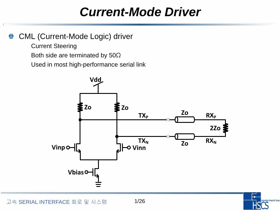
CML (Current-Mode Logic) driver– Current Steering
– Both side are terminated by 50Ω
– Used in most high-performance serial link
Vinp
Vbias
Vinn
Vdd
Zo
Zo
2Zo
ZoZoRXP
RXN
TXP
TXN
2/26고속 SERIAL INTERFACE 회로및시스템
Current-Mode Driver
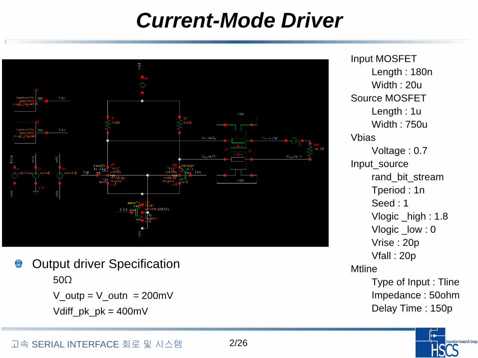
Output driver Specification
– 50Ω
– V_outp = V_outn = 200mV
– Vdiff_pk_pk = 400mV
– Input MOSFET
• Length : 180n
• Width : 20u
– Source MOSFET
• Length : 1u
• Width : 750u
– Vbias
• Voltage : 0.7
– Input_source
• rand_bit_stream
• Tperiod : 1n
• Seed : 1
• Vlogic _high : 1.8
• Vlogic _low : 0
• Vrise : 20p
• Vfall : 20p
– Mtline
• Type of Input : Tline
• Impedance : 50ohm
• Delay Time : 150p
3/26고속 SERIAL INTERFACE 회로및시스템
Current-Mode Driver
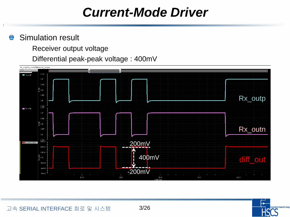
Simulation result
– Receiver output voltage
– Differential peak-peak voltage : 400mV
Rx_outp
diff_out
Rx_outn
400mV
200mV
-200mV
4/26고속 SERIAL INTERFACE 회로및시스템
Current-Mode Driver
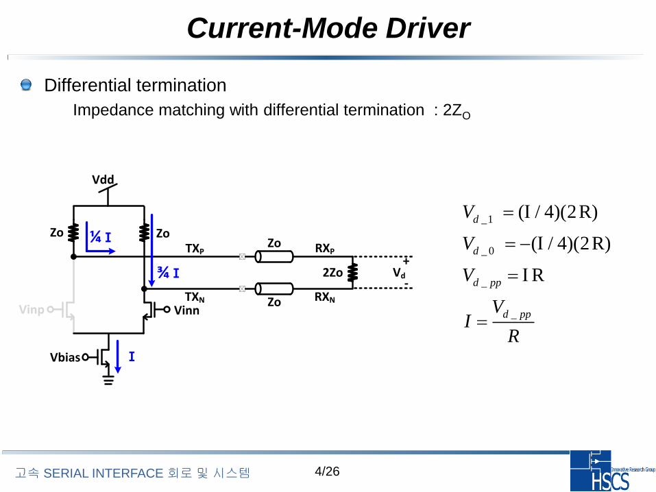
Differential termination
– Impedance matching with differential termination : 2ZO
Vinp
Vbias
Vinn
Vdd
Zo
Zo
2Zo
ZoZoRXP
RXN
TXP
TXN
¼Ⅰ
¾ Ⅰ
Ⅰ
Vd
+
-
_1
_ 0
_
_
( / 4)(2R)
( / 4)(2R)
R
d
d
d pp
d pp
V
V
V
VI
R
5/26고속 SERIAL INTERFACE 회로및시스템
Current-Mode Driver
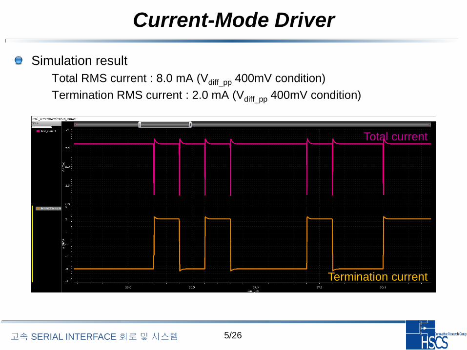
Simulation result
– Total RMS current : 8.0 mA (Vdiff_pp 400mV condition)
– Termination RMS current : 2.0 mA (Vdiff_pp 400mV condition)
Total current
Termination current
6/26고속 SERIAL INTERFACE 회로및시스템
Current-Mode Driver
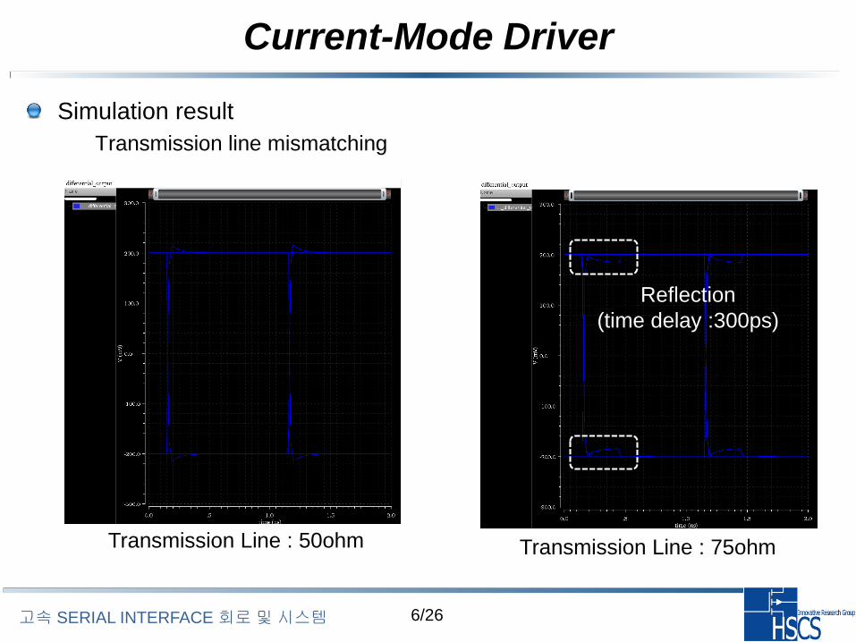
Simulation result
– Transmission line mismatching
Transmission Line : 50ohm Transmission Line : 75ohm
Reflection
(time delay :300ps)
7/26고속 SERIAL INTERFACE 회로및시스템
Current-Mode Driver
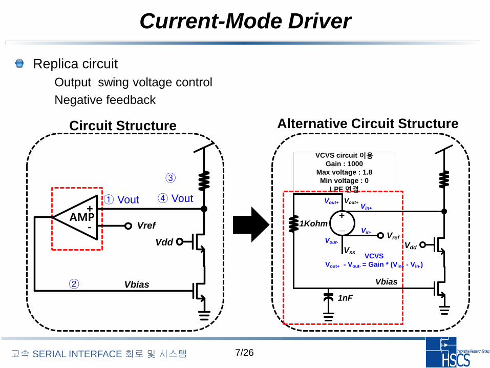
Replica circuit
– Output swing voltage control
– Negative feedback
Circuit Structure Alternative Circuit Structure
① Vout ↑
③ Id ↑
④ Vout ↓
②Vbias↑
Vdd
VrefAMP
+
-
Vbias
Vdd
Vref
+_
Vss
VCVS circuit 이용Gain : 1000
Max voltage : 1.8
Min voltage : 0
LPF 연결
1Kohm
1nF
Vin+
VCVS
Vout+ - Vout- = Gain * (Vin+ - Vin-)
Vin-
Vout+Vout+
Vout-
Vbias

8/26고속 SERIAL INTERFACE 회로및시스템
Current-Mode Driver
Schematic design
9/26고속 SERIAL INTERFACE 회로및시스템
Current-Mode Driver
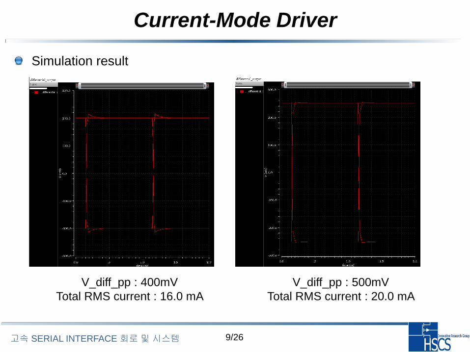
Simulation result
V_diff_pp : 400mV
Total RMS current : 16.0 mA
V_diff_pp : 500mV
Total RMS current : 20.0 mA
10/26고속 SERIAL INTERFACE 회로및시스템
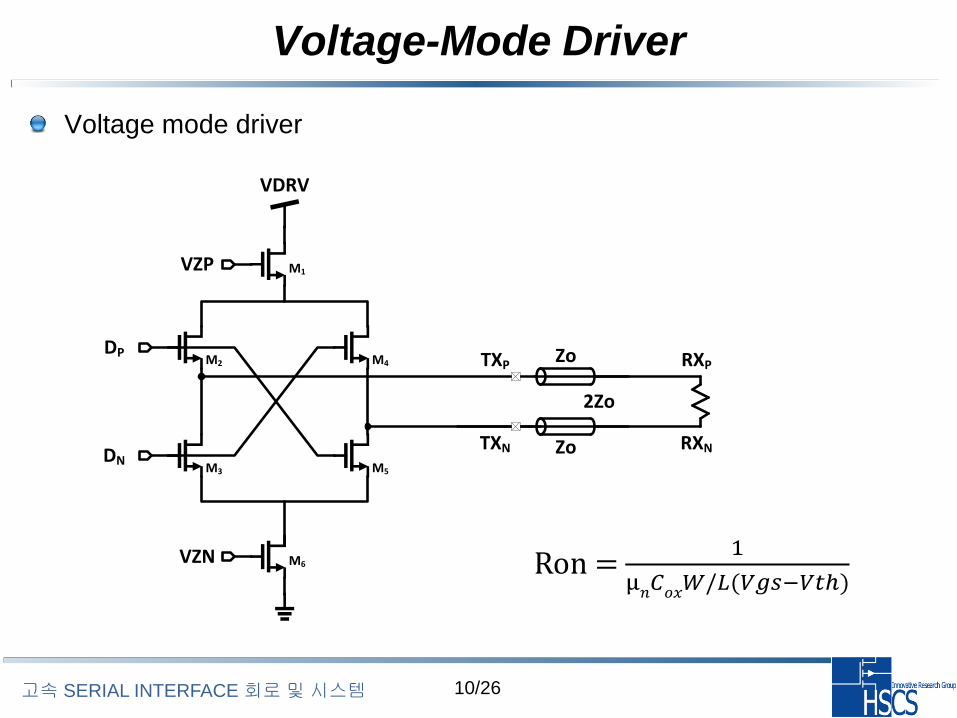
Voltage-Mode Driver
Voltage mode driver
Zo
Zo
2Zo
RXP
RXN
TXP
TXN
DP
DN
VZN
VZP
VDRV
M1
M2
M3 M5
M4
M6 Ron = 1
μ𝑛𝐶𝑜𝑥𝑊/𝐿(𝑉𝑔𝑠−𝑉𝑡ℎ)
11/26고속 SERIAL INTERFACE 회로및시스템
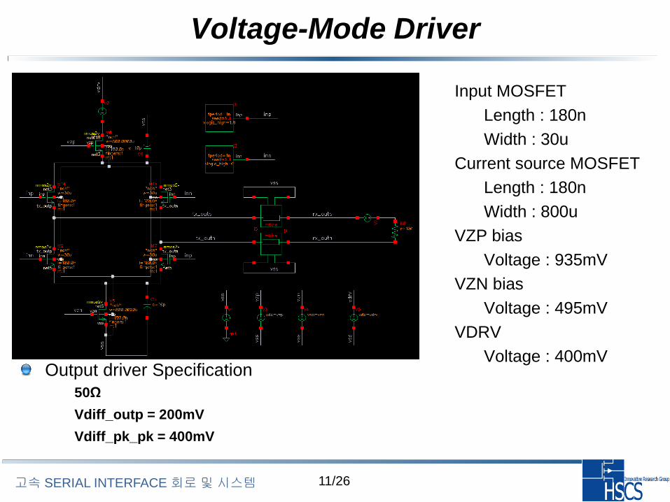
Voltage-Mode Driver
Output driver Specification
– 50Ω
– Vdiff_outp = 200mV
– Vdiff_pk_pk = 400mV
– Input MOSFET
• Length : 180n
• Width : 30u
– Current source MOSFET
• Length : 180n
• Width : 800u
– VZP bias
• Voltage : 935mV
– VZN bias
• Voltage : 495mV
– VDRV
• Voltage : 400mV

12/26고속 SERIAL INTERFACE 회로및시스템
Voltage-Mode Driver
Simulation result
– Output swing voltage
Rx_outp
Diff_out
Rx_outn
200mV
300mV
100mV
400mV
200mV
-200mV
13/26고속 SERIAL INTERFACE 회로및시스템
Voltage-Mode Driver
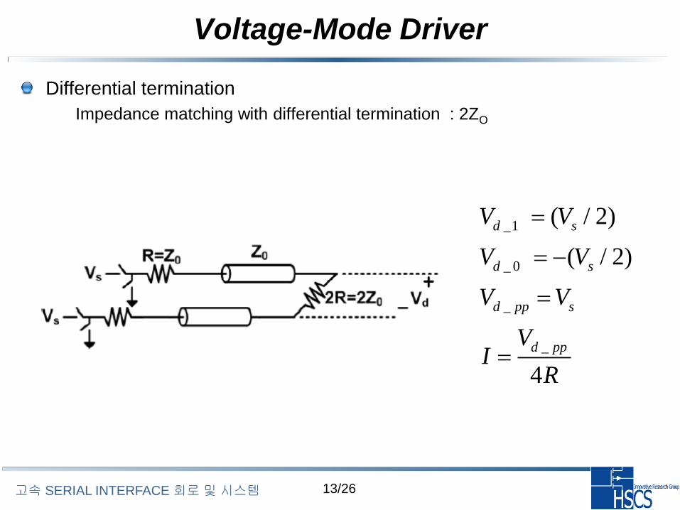
Differential termination
– Impedance matching with differential termination : 2ZO
_1
_ 0
_
_
( / 2)
( / 2)
4
d s
d s
d pp s
d pp
V V
V V
V V
VI
R
14/26고속 SERIAL INTERFACE 회로및시스템
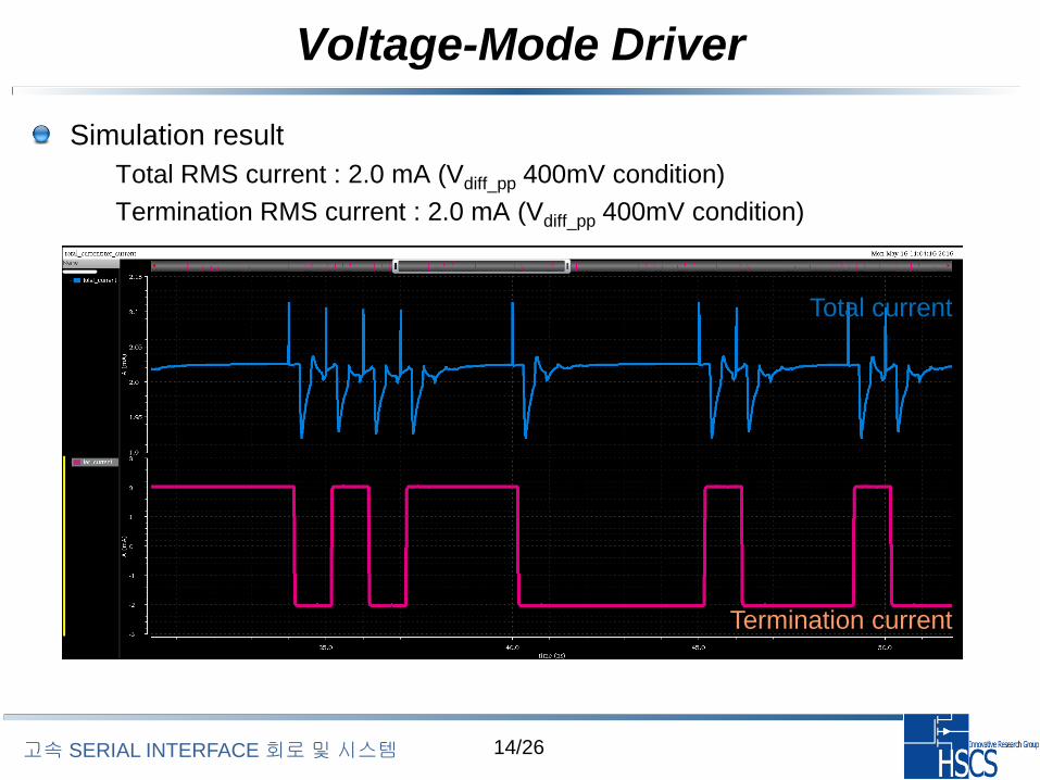
Voltage-Mode Driver
Simulation result
– Total RMS current : 2.0 mA (Vdiff_pp 400mV condition)
– Termination RMS current : 2.0 mA (Vdiff_pp 400mV condition)
Total current
Termination current
15/26고속 SERIAL INTERFACE 회로및시스템
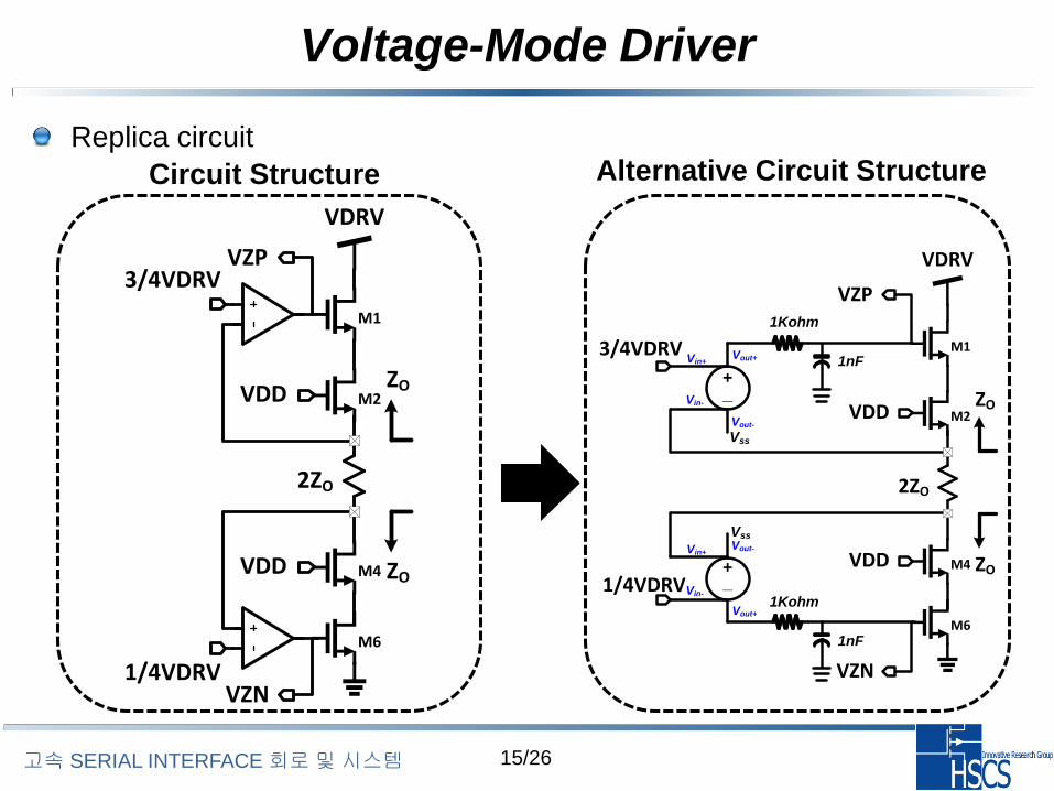
Voltage-Mode Driver
Replica circuit
Circuit Structure Alternative Circuit Structure
VDD
VDD
VDRV
2ZO
3/4VDRV
1/4VDRVVZN
VZP
M1
M2
M4
M6
ZO
ZO
+_
VDD
VDD
VDRV
2ZO
3/4VDRV
1/4VDRV
VZN
VZP
M1
M2
M4
M6
ZO
ZO
Vss
Vin+
Vin-
+_
Vin+
Vin-
Vout+
Vout-
Vss
Vout+
Vout-
1nF
1Kohm
1nF
1Kohm
16/26고속 SERIAL INTERFACE 회로및시스템
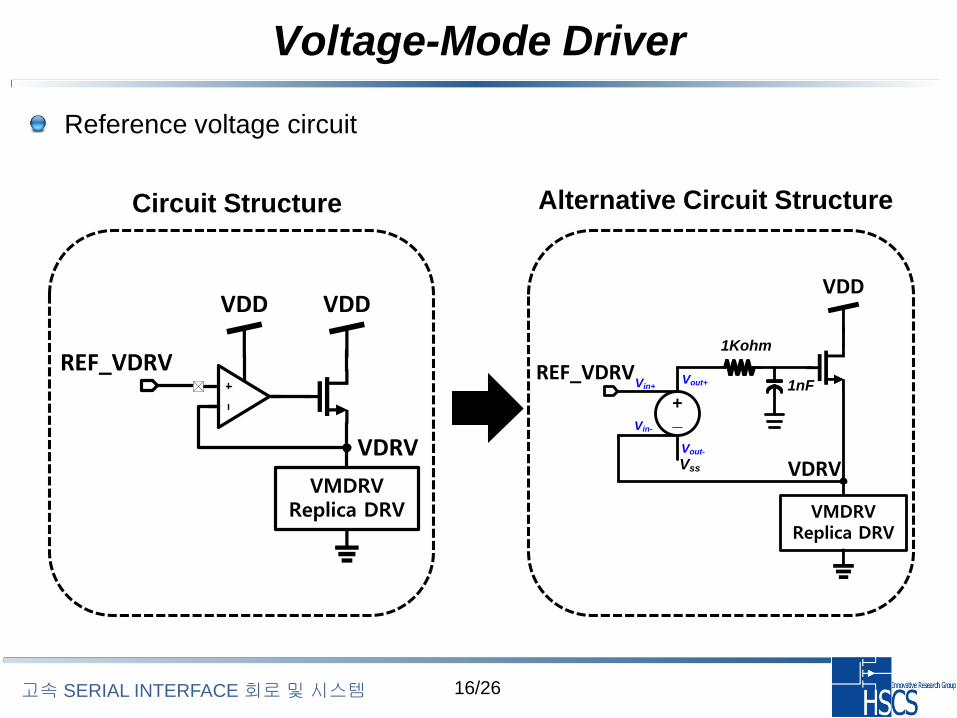
Voltage-Mode Driver
Reference voltage circuit
Circuit Structure Alternative Circuit Structure
VMDRVReplica DRV
VDDVDD
VDRV
REF_VDRV
VMDRVReplica DRV
VDD
VDRV
+_
REF_VDRV
Vss
Vin+
Vin-
Vout+
Vout-
1nF
1Kohm
17/26고속 SERIAL INTERFACE 회로및시스템
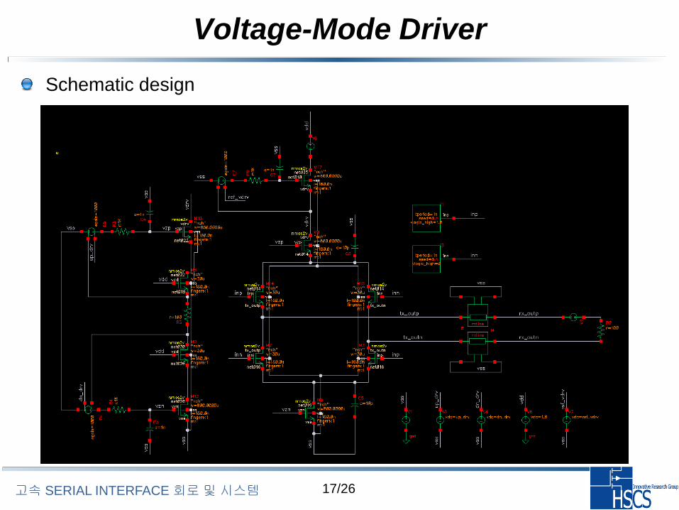
Voltage-Mode Driver
Schematic design
18/26고속 SERIAL INTERFACE 회로및시스템
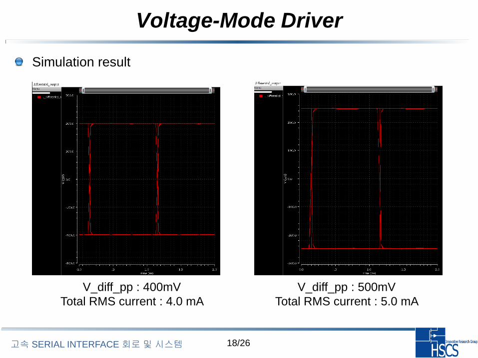
Voltage-Mode Driver
Simulation result
V_diff_pp : 400mV
Total RMS current : 4.0 mA
V_diff_pp : 500mV
Total RMS current : 5.0 mA
19/26고속 SERIAL INTERFACE 회로및시스템
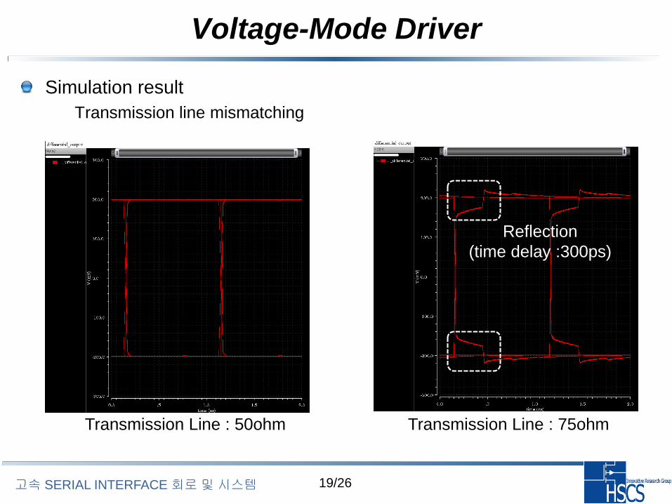
Voltage-Mode Driver
Simulation result
– Transmission line mismatching
Transmission Line : 50ohm Transmission Line : 75ohm
Reflection
(time delay :300ps)
20/26고속 SERIAL INTERFACE 회로및시스템
Voltage-Mode Driver
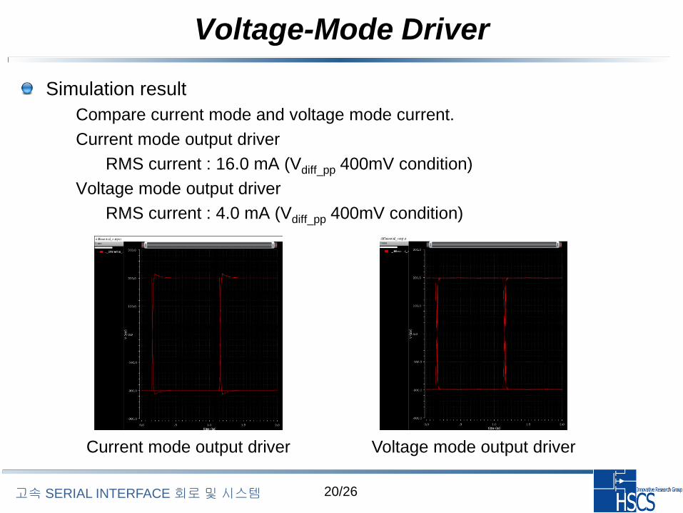
Simulation result
– Compare current mode and voltage mode current.
– Current mode output driver
• RMS current : 16.0 mA (Vdiff_pp 400mV condition)
– Voltage mode output driver
• RMS current : 4.0 mA (Vdiff_pp 400mV condition)
Current mode output driver Voltage mode output driver
21/26고속 SERIAL INTERFACE 회로및시스템
Exercise
Current mode and voltage mode output driver
– Design Vpk_pk 600mV Current and voltage mode driver with 50ohm
impedance.
• Derive mosfet size.
• Plot the output waveform and current waveform.
• Compare and analyze between current mode and voltage mode output
driver.
• Plot the eye diagram in case of transmission line impedance 75ohm and
50ohm. (Differential Rx termination 50ohm condition)
• Plot the eye diagram in case of differential rx termination 75ohm and
50ohm. (Transmission line impedance 50ohm condition)


![FARM Tx pada PEDIATRI,2014 [Compatibility Mode].pdf](https://static.fdocument.pub/doc/165x107/55cf9408550346f57b9f2ac3/farm-tx-pada-pediatri2014-compatibility-modepdf.jpg)