
UNIVERSAL TUBULAR SENSORS
48
UNIVERSAL TUBULAR SENSORS • Complete range of optic functions, universal, application and laser class 1 • Flat plastic tubular housing for improved versatility or metal cylindrical housing • Versions with axial or radial optics, with fixed, trimmer or EASYtouch™ teach-in adjustment • Cable or M12 connection with EN standard NPN or PNP NO-NC configuration The S50 series offers virtually all optical functions within an M18 housing. With the universal sensing functions of proximity, polarised retroreflex and through beam, which are also available with class 1 laser emission, as well as the more advanced functions of background suppression, background/foreground suppression, analogue displacement, contrast and luminescence, the S50 really is one housing for all applications. The S50 setting is carried out-by either by potentiometer, which is sealed to IP67, or using the patented EASYtouch™ push-button teach system, which gives rapid and precise automatic setting of the switching points. The S50 series is available both in flat plastic format ideal for M18 nut or screw mounting through the sensor body, as well as a cylindrical metallic housing. Axial or radial optics are available in both housings with integral cable or M12 connection conforming to EN 60947-5-2, the European wiring standard. The performance, versatility and extensive optical sensing options, positions the S50 series as the new bench mark for customers focused on the evolution of technology and development of standards. S50 SERIES TUB M18 MULTIFUNCTION OPTOELECTRONIC SENSORS one for all
Transcript of UNIVERSAL TUBULAR SENSORS

UN
IVER
SAL
TUB
ULA
R S
ENSO
RS
• Complete range of optic functions, universal, applicationand laser class 1
• Flat plastic tubular housing for improved versatility ormetal cylindrical housing
• Versions with axial or radial optics, with fixed, trimmer orEASYtouch™ teach-in adjustment
• Cable or M12 connection with EN standard NPN or PNPNO-NC configuration
The S50 series offers virtually all optical functions within an M18 housing. With theuniversal sensing functions of proximity, polarised retroreflex and through beam,which are also available with class 1 laser emission, as well as the moreadvanced functions of background suppression, background/foregroundsuppression, analogue displacement, contrast and luminescence, the S50 really isone housing for all applications.The S50 setting is carried out-by either by potentiometer, which is sealed to IP67,or using the patented EASYtouch™ push-button teach system, which gives rapidand precise automatic setting of the switching points.The S50 series is available both in flat plastic format ideal for M18 nut or screwmounting through the sensor body, as well as a cylindrical metallic housing. Axialor radial optics are available in both housings with integral cable or M12connection conforming to EN 60947-5-2, the European wiring standard. Theperformance, versatility and extensive optical sensing options, positions the S50series as the new bench mark for customers focused on the evolution oftechnology and development of standards.
S50 SERIES
TUB
M18 MULTIFUNCTION OPTOELECTRONICSENSORS
one for all

DIMENSIONS
INDICATORS AND SETTINGS
ACCESSORIES
For dedicated accessories refer to theACCESSORIES section of this catalogue.
Refer also to Connectors (A.03) and Fixingbrackets (A.04) of the General Catalogue.
OUTPUT status andstability LEDs (receiver);power on LED (emitter)
Adjustment tr immer(receiver)
M12 connector output
Cable output
Fixing nuts
Fixing gasket
B
B
F
F
D
C C
CC
E
A
B
C
D
E
F
THROUGH BEAM WITH INFRARED EMISSION
CONNECTIONS
Single-turn trimmer for sensitivity adjustment. Rotate in aclockwise direction to increase the operating distance.
EMITTER
RECEIVER
B
EMITTER
S50-PA/PR-5S50-PA/PR-2
Versions and options: refer to MODEL ALPHABETICAL INDEX of this catalogue.
RECEIVER
RADIAL OPTICS
2
A
Longer operating distances can beobtained utilising separate emitterand receiver units. The infraredemission is modulated to avoidinterference with other lightsources and the emitter is fittedwith test inputs for remote systeminterrogation.
G/F

receiver - axial optics - 2 m cableS50-PA-2-F01-NN 952001660 NPNS50-PA-2-F01-PP 952001150 PNP
emitter - axial optics - 2 m cableS50-PA-2-G00-XG 952001190
receiver - radial optics - 2 m cable S50-PR-2-F01-NN 952001820 NPNS50-PR-2-F01-PP 952001170 PNP
emitter - radial optics - 2 m cable S50-PR-2-G00-XG 952001210
receiver - axial optics - M12 connector S50-PA-5-F01-NN 952001550 NPNS50-PA-5-F01-PP 952001160 PNP
emitter - axial optics - M12 connector S50-PA-5-G00-XG 952001200
receiver - radial optics - M12 connector S50-PR-5-F01-NN 952001760 NPNS50-PR-5-F01-PP 952001180 PNP
emitter - radial optics - M12 connector S50-PR-5-G00-XG 952001220
DETECTION DIAGRAMS
TECHNICAL NOTES
2 Average life of 100.000 h with TA = +25 °C3 270° single-turn trimmer 4 Emitter off with Test+ on Vdc and Test- on 0 V5 PVC, 4 x 0.14 mm2
0 5 10 15 20 (m)
Recommended operating distance Maximum operating distance
axial
radial
15
10
20
15
TECHNICAL DATA
Operating distance:axial optics 0 ... 20 mradial optics 0 ... 15 m
Power supply: 10 ... 30 Vdc Ripple: ≤ 2 Vpp Consumption:
emitter ≤ 35 mAreceiver ≤ 30 mA
Light emission: infrared LED 880 nmSpot dimension:
axial optics aprox. 500 mm at 15 mradial optics aprox. 470 mm at 10 m
Setting: sensitivity trimmer Indicators:
yellow OUTPUT LED green STABILITY LED green POWER ON LED
Output type:PNP, NO and NCNPN, NO and NC
Output current: ≤ 100 mASaturation voltage: ≤ 2 V Response time: 2 ms Switching frequency: 250 Hz Operating mode: dark on NO / light on NCAuxiliary functions: Test + and Test -Connection:
2 m Ø 4 mm cableM12 4-pole connector
Electrical protection: class 2Mechanical protection: IP67Protection devices: A, BHousing material: PBTLens material: PMMAWeight:
75 g max. 25 g max.
Operating temperature: -25 ... +55°C Storage temperature: -25 ... +70°CReference standard: EN 60947-5-2
1
3
4
5
6
7
2
S50-
PA-2
-F01
-NN
S50-
PA-2
-F01
-PP
S50-
PA-2
-G00
-XG
S50-
PR-2
-F01
-NN
S50-
PR-2
-F01
-PP
S50-
PR-2
-G00
-XG
S50-
PA-5
-F01
-NN
S50-
PA-5
-F01
-PP
S50-
PA-5
-G00
-XG
S50-
PR-5
-F01
-NN
S50-
PR-5
-F01
-PP
S50-
PR-5
-G00
-XG
6 Compatible with quick connection systems
Detection areaExcess gain
axial
axial
radial
1 Limit values
7 A - reverse polarity protection B - overload and short-circuit protection on
receiver outputs
3
SELECTION TABLE
All the ordering codes and information aresummarised in the last pages of this catalogue.
radial
S50-PA/PR 20 m

Longer operating distances can beobtained utilising separate emitterand receiver units. The infraredemission is modulated to avoidinterference with other lightsources and the emitter is fittedwith test inputs for remote systeminterrogation.
DIMENSIONS
ACCESSORIES
For dedicated accessories refer to theACCESSORIES section of this catalogue.
Refer also to Connectors (A.03) and Fixingbrackets (A.04) of the General Catalogue.
D E
THROUGH BEAM WITH INFRARED EMISSION
Single-turn trimmer for sensitivity adjustment. Rotate in aclockwise direction to increase the operating distance.
EMITTER
RECEIVER
S50-MA/MR-5S50-MA/MR-2
B B
RADIAL OPTICS
4
INDICATORS AND SETTINGS OUTPUT status andstability LEDs (receiver);power on LED (emitter)
Adjustment tr immer(receiver)
M12 connector output
Cable output
Fixing nuts
A
B
C
D
E
CONNECTIONS
C C
CC
B
A
Versions and options: refer to MODEL ALPHABETICAL INDEX of this catalogue.
EMITTER
RECEIVER
G/F

5
TECHNICAL DATA
TECHNICAL NOTES
Operating distance:axial optics 0 ... 20 mradial optics 0 ... 15 m
Power supply: 10 ... 30 Vdc Ripple: ≤ 2 Vpp Consumption:
emitter ≤ 35 mAreceiver ≤ 30 mA
Light emission: infrared LED 880 nmSpot dimension:
axial optics aprox. 500 mm at 15 mradial optics aprox. 470 mm at 10 m
Setting: sensitivity trimmer Indicators:
yellow OUTPUT LED green STABILITY LED green POWER ON LED
Output type:PNP, NO and NCNPN, NO and NC
Output current: ≤ 100 mASaturation voltage: ≤ 2 V Response time: 2 ms Switching frequency: 250 Hz Operating mode: dark on NO / light on NCAuxiliary functions: Test + and Test -Connection:
2 m Ø 4 mm cableM12 4-pole connector
Electrical protection: class 2Mechanical protection: IP67Protection devices: A, BHousing material: nickel plated brassLens material: PMMAWeight:
110 g max. 60 g max.
Operating temperature: -25 ... +55°C Storage temperature: -25 ... +70°CReference standard: EN 60947-5-2
S50-
MA
-2-F
01-N
N
S50-
MA
-2-F
01-P
PS5
0-M
A-2
-G00
-XG
S50-
MR
-2-F
01-N
NS5
0-M
R-2
-F01
-PP
S50-
MR
-2-G
00-X
GS5
0-M
A-5
-F01
-NN
S50-
MA
-5-F
01-P
PS5
0-M
A-5
-G00
-XG
S50-
MR
-5-F
01-N
NS5
0-M
R-5
-F01
-PP
S50-
MR
-5-G
00-X
G
1
3
4
5
7
6
2
DETECTION DIAGRAMS
0 5 10 15 20 (m)
Recommended operating distance Maximum operating distance
axial
radial
15
10
20
15
2 Average life of 100.000 h with TA = +25 °C3 270° single-turn trimmer 4 Emitter off with Test+ on Vdc and Test- on 0 V5 PVC, 4 x 0.14 mm2
6 Compatible with quick connection systems
1 Limit values
7 A - reverse polarity protection B - overload and short-circuit protection on
receiver outputs
SELECTION TABLE
All the ordering codes and information aresummarised in the last pages of this catalogue.
receiver - axial optics - 2 m cable S50-MA-2-F01-NN 952021540 NPNS50-MA-2-F01-PP 952021050 PNP
emitter - axial optics - 2 m cable S50-MA-2-G00-XG 952021060
receiver - radial optics - 2 m cable S50-MR-2-F01-NN 952021640 NPNS50-MR-2-F01-PP 952021170 PNP
emitter - radial optics - 2 m cable S50-MR-2-G00-XG 952021180
receiver - axial optics - M12 connector S50-MA-5-F01-NN 952021800 NPNS50-MA-5-F01-PP 952021310 PNP
emitter - axial optics - M12 connector S50-MA-5-G00-XG 952021260
receiver - radial optics - M12 connector S50-MR-5-F01-NN 952021800 NPNS50-MR-5-F01-PP 952021370 PNP
emitter - radial optics - M12 connector S50-MR-5-G00-XG 952021380
Detection areaExcess gain
axial
radial
axial
radial
S50-MA/MR 20 m

NOT USED
TEST +
DIMENSIONS
INDICATORS AND SETTINGS
ACCESSORIES
For dedicated accessories refer to theACCESSORIES section of this catalogue.
Refer also to Connectors (A.03) and Fixingbrackets (A.04) of the General Catalogue.
OUTPUT status andpower on LED
Adjustment tr immer(receiver)
M12 connector output
Cable output
Fixing nuts
Fixing gasket
B
B
F
F
D
C C
CC
E
A
B
C
D
E
F
CONNECTIONS
Single-turn trimmer for sensitivity adjustment. Rotate in aclockwise direction to increase the operating distance.Decrease sensitivity to increase resolution.
EMITTER
RECEIVER
B
EMITTER
S50-PL/PH-5S50-PL/PH-2
Versions and options: refer to MODEL ALPHABETICAL INDEX of this catalogue.
RECEIVER
RADIAL OPTICS
6
A
The high operating distance typicalof emitter and receiver pairs isnotably increased thanks to theuse of visible red laser emission.The laser beam can be easilyaligned and offers excellentdetection resolution of even smallobjects. The class 1 laser emissionguarantees maximum safety for theoperators in all applications.
LASER THROUGH BEAM WITH RED EMISSIONL-G/F

7
S50-PL/PH 60 m
TECHNICAL DATA
Operating distance:axial optics 0 ... 60 mradial optics 0 ... 50 m
Power supply: 10 ... 30 Vdc Ripple: ≤ 2 Vpp Consumption:
emitter ≤ 35 mAreceiver ≤ 30 mA
Light emission:red Laser 650 nmclass 1 EN 60825-1class II CDRH21 CFR 1040.10
Resolution:aprox. 5 mm at 0.5 maprox. 6.5 mm over 1 m
Setting: sensitivity trimmer Indicators:
yellow OUTPUT LED green POWER ON LED
Output type:PNP, NO and NCNPN, NO and NC
Output current: ≤ 100 mASaturation voltage: ≤ 2 V Response time: 333 µs Switching frequency: 1.5 kHz Operating mode: dark on NO / light on NCAuxiliary functions: Test +Connection:
2 m Ø 4 mm cableM12 4-pole connector
Electrical protection: class 2Mechanical protection: IP67Protection devices: A, BHousing material: PBTLens material: PMMA / glassWeight:
75 g max. 25 g max.
Operating temperature: -10 ... +50°C Storage temperature: -25 ... +70°CReference standard: EN 60947-5-2,
EN 60825-1, CDRH21 CFR 1040.10
1
3
4
5
6
7
2
S50-
PL-2
-G00
-XG
S50-
PL-2
-F01
-NN
S50-
PL-2
-F01
-PP
S50-
PL-5
-G00
-XG
S50-
PL-5
-F01
-NN
S50-
PL-5
-F01
-PP
S50-
PH-2
-G00
-XG
S50-
PH-2
-F01
-NN
S50-
PH-2
-F01
-PP
S50-
PH-5
-G00
-XG
S50-
PH-5
-F01
-NN
S50-
PH-5
-F01
-PP
TECHNICAL NOTES1 Limit values2 Average life of 50.000 h with TA = +25 °C3 270° single-turn trimmer 4 Emitter off with Test+ connected to +Vcc
Emitter on with Test+ not connected or connected to 0V
5 PVC, 4 x 0.14 mm2
SELECTION TABLEemitter - axial optics - 2 m cable S50-PL-2-G00-XG 952001420
receiver - axial optics - 2 m cable S50-PL-2-F01-NN 952001890 NPNS50-PL-2-F01-PP 952001400 PNP
emitter - radial optics - 2 m cable S50-PH-2-G00-XG 952002060
receiver - radial optics - 2 m cable S50-PH-2-F01-NN 952002030 NPNS50-PH-2-F01-PP 952002020 PNP
emitter - axial optics - M12 connectorS50-PL-5-G00-XG 952001430
receiver - axial optics - M12 connectorS50-PL-5-F01-NN 952001860 NPNS50-PL-5-F01-PP 952001410 PNP
emitter - radial optics - M12 connectorS50-PH-5-G00-XG 952002070
receiver - radial optics - M12 connectorS50-PH-5-F01-NN 952002050 NPNS50-PH-5-F01-PP 952002040 PNP
All the ordering codes and information aresummarised in the last pages of this catalogue.
6 Compatible with quick connection systems 7 A - reverse polarity protection
B - overload and short-circuit protection on receiver outputs
DETECTION DIAGRAMS
0 15 30 45 60 (m)
Operating distance
60
50
Resolution - axialDetection area - axial
Detection area - radial Resolution - radial
radial
axial

DIMENSIONS
INDICATORS AND SETTINGS
ACCESSORIES
For dedicated accessories refer to theACCESSORIES section of this catalogue.
Refer also to Connectors (A.03) and Fixingbrackets (A.04) of the General Catalogue.
OUTPUT status andpower on LED
Adjustment tr immer(receiver)
M12 connector output
Cable output
Fixing nuts
Fixing gasket
A
B
C
D
E
F
CONNECTIONS
B
The high operating distance typicalof emitter and receiver pairs isnotably increased thanks to the useof visible red laser emission. Thelaser beam can be easily alignedand offers excellent detectionresolution of even small objects.The class 1 laser emissionguarantees maximum safety for theoperators in all applications.
S50-ML/MH-5S50-ML/MH-2EMITTER
8
Single-turn trimmer for sensitivity adjustment. Rotate in aclockwise direction to increase the operating distanceDecrease sensitivity to increase resolution.
A
NOT USED
TEST +
Versions and options: refer to MODEL ALPHABETICAL INDEX of this catalogue.
RECEIVER
LASER THROUGH BEAM WITH RED EMISSIONL-G/F
RADIAL OPTICS
D E
EMITTER
RECEIVER
B B
C C
CC

Operating distance:axial optics 0 ... 60 mradial optics 0 ... 50 m
Power supply: 10 ... 30 Vdc Ripple: ≤ 2 Vpp Consumption:
emitter ≤ 35 mAreceiver ≤ 30 mA
Light emission:red Laser 650 nmclass 1 EN 60825-1class II CDRH21 CFR 1040.10
Resolution:aprox. 5 mm at 0.5 maprox. 6.5 mm over 1 m
Setting: sensitivity trimmer Indicators:
yellow OUTPUT LED green POWER ON LED
Output type:PNP, NO and NCNPN, NO and NC
Output current: ≤ 100 mASaturation voltage: ≤ 2 V Response time: 333 µs Switching frequency: 1.5 kHz Operating mode: dark on NO / light on NCAuxiliary functions: Test +Connection:
2 m Ø 4 mm cableM12 4-pole connector
Electrical protection: class 2Mechanical protection: IP67Protection devices: A, BHousing material: nickel plated brassLens material: PMMA / glassWeight:
75 g max. 25 g max.
Operating temperature: -10 ... +50°C Storage temperature: -25 ... +70°CReference standard: EN 60947-5-2,
EN 60825-1, CDRH21 CFR 1040.10
1
3
4
5
6
7
2
TECHNICAL NOTES1 Limit values2 Average life of 50.000 h with TA = +25 °C3 270° single-turn trimmer 4 Emitter off with Test+ connected to +Vcc
Emitter on with Test+ not connected or connected to 0V
6 Compatible with quick connection systems 7 A - reverse polarity protection
B - overload and short-circuit protection on receiver outputs
DETECTION DIAGRAMS
0 15 30 45 60 (m)
Operating distance
60
50
Resolution - axialDetection area - axial
Detection area - radial Resolution - radial
radial
axial
9
S50-ML/MH 60 m
TECHNICAL DATA
S50-
ML-
2-G
00-X
G
S50-
ML-
2-F0
1-N
NS5
0-M
L-2-
F01-
PPS5
0-M
L-5-
G00
-XG
S50-
ML-
5-F0
1-N
NS5
0-M
L-5-
F01-
PPS5
0-M
H-2
-G00
-XG
S50-
MH
-2-F
01-N
NS5
0-M
H-2
-F01
-PP
S50-
MH
-5-G
00-X
GS5
0-M
H-5
-F01
-NN
S50-
MH
-5-F
01-P
P
SELECTION TABLEemitter - axial optics - 2 m cable S50-ML-2-G00-XG 952021430
receiver - axial optics - 2 m cable S50-ML-2-F01-NN 952021840 NPNS50-ML-2-F01-PP 952021420 PNP
emitter - radial optics - 2 m cable S50-MH-2-G00-XG 952022060
receiver - radial optics - 2 m cable S50-MH-2-F01-NN 952022030 NPNS50-MH-2-F01-PP 952022020 PNP
emitter - axial optics - M12 connectorS50-ML-5-G00-XG 952021470
receiver - axial optics - M12 connectorS50-ML-5-F01-NN 952021870 NPNS50-ML-5-F01-PP 952021460 PNP
emitter - radial optics - M12 connectorS50-MH-5-G00-XG 952022070
receiver - radial optics - M12 connectorS50-MH-5-F01-NN 952022050 NPNS50-MH-5-F01-PP 952022040 PNP
All the ordering codes and information aresummarised in the last pages of this catalogue.

RETROREFLEX WITH INFRARED EMISSIONWith retroreflex sensors the objectis detected when it interrupts thelight beam generated between thesensor and its associatedprismatic reflector. This retroreflexsystem, created between thesensor and the reflector, offers theadvantage of electricallyconnecting one single unit insteadof two, as in the emitter-receiversystem.
ACCESSORIES
For dedicated accessories refer to theACCESSORIES section of this catalogue.
Refer also to Connectors (A.03) and Fixingbrackets (A.04) of the General Catalogue.
DIMENSIONS
INDICATORS AND SETTINGS OUTPUT status LED
M12 connector output
Cable output
Fixing nuts
Fixing gasket
A
C
D
E
F
CONNECTIONS
S50-XX-5S50-XX-2
D E
F
Versions and options: refer to MODEL ALPHABETICAL INDEX of this catalogue.
PLASTIC HOUSING
METAL HOUSING
C
10
C
A
A
A

5 (m)
DETECTION DIAGRAMS
11
S50-PA 5 mS50-MA
TECHNICAL NOTES1 Limit values2 Average life of 100.000 h with TA = +25 °C43 PVC, 4 x 0.14 mm2
4 Compatible with quick connection systems 5 A - reverse polarity protection
B - overload and short-circuit protection on the outputs
TECHNICAL DATA
Operating distance: 0.1 ... 5 m Power supply: 10 ... 30 Vdc Ripple: ≤ 2 Vpp Consumption: ≤ 35 mALight emission: infrared LED 880 nmSpot dimension: aprox. 100 mm at 2 mIndicators: yellow OUTPUT LED Output type:
PNP, NO and NCNPN, NO and NC
Output current: ≤ 100 mASaturation voltage: ≤ 2 V Response time: 0.5 ms Switching frequency: 1 kHz Operating mode: dark on NO / light on NCConnection:
2 m Ø 4 mm cableM12 4-pole connector
Electrical protection: class 2Mechanical protection: IP67Protection devices: A, BHousing material:
PBTnickel plated brass
Lens material: PMMAWeight:
75 g max. 25 g max. 110 g max. 60 g max.
Operating temperature: -25 ... +55°C Storage temperature: -25 ... +70°CReference standard: EN 60947-5-2
1
3
4
5
2
S50-
PA-2
-A00
-NN
S50-
PA-2
-A00
-PP
S50-
PA-5
-A00
-NN
S50-
PA-5
-A00
-PP
S50-
MA
-2-A
00-N
N
S50-
MA
-2-A
00-P
PS5
0-M
A-5
-A00
-NN
S50-
MA
-5-A
00-P
P
SELECTION TABLEplastic - axial optics - cable 2 mS50-PA-2-A00-NN 952002090 NPNS50-PA-2-A00-PP 952002080 PNP
metal - axial optics - 2 m cable S50-MA-2-A00-NN 952022090 NPNS50-MA-2-A00-PP 952022080 PNP
plastic - axial optics - M12 connector S50-PA-5-A00-NN 952002110 NPNS50-PA-5-A00-PP 952002100 PNP
metal - axial optics - M12 connector S50-MA-5-A00-NN 952022110 NPNS50-MA-5-A00-PP 952022100 PNP
All the ordering codes and information aresummarised in the last pages of this catalogue.
Detection areaExcess gain
R2R5
R2 R5
10.1 2 3 4
Operating distance
axial on R5 5
axial on R2 4

POLARISED RETROREFLEX WITH RED EMISSION
DIMENSIONS
INDICATORS AND SETTINGS
ACCESSORIES
For dedicated accessories refer to theACCESSORIES section of this catalogue.
Refer also to Reflectors (A.01), Connectors(A.03) and Fixing brackets (A.04) of theGeneral Catalogue.
OUTPUT status andstability LEDs
Adjustment trimmer
M12 connector output
Cable output
Fixing nuts
Fixing gasket
A
B
C
D
E
F
CONNECTIONS
Single-turn trimmer for sensitivity adjustment. Rotate in aclockwise direction to increase the operating distance.
Versions and options: refer to MODEL ALPHABETICAL INDEX of this catalogue.
B
B
S50-XX-5S50-XX-2
RADIAL OPTICS
12
D E
F B F
PLASTIC HOUSING
METAL HOUSING
B C
C C
CB
B
A
A
With retroreflex sensors the objectis detected when it interrupts thelight beam generated between thesensor and its associatedprismatic reflector. High-polarisation optic filters also allowreliable detection of very reflectiveobjects, such as mirrored surfacesthat, differently from the prismaticreflector, reflect the light beamwithout rotating the polarisationplane.
B

DETECTION DIAGRAMS
TECHNICAL NOTES1 Limit values2 Average life of 100.000 h with TA = +25 °C3 270° single-turn trimmer 4 PVC, 4 x 0.14 mm2
5 Compatible with quick connection systems 6 A - reverse polarity protection
B - overload and short-circuit protection on the outputs
10.1 2 3 4 5 (m)
axial on R2 3.5
4.5
4
TECHNICAL DATA
Operating distance:axial optics 0.1 ... 1.7 m radial optics 0.1 ... 3 m
Power supply: 10 ... 30 Vdc Ripple: ≤ 2 Vpp Consumption: ≤ 35 mALight emission: red LED 660 nmSpot dimension:
axial optics aprox. 45 mm at 1 mradial optics aprox. 60 mm at 2 m
Setting: sensitivity trimmer Indicators:
yellow OUTPUT LED green STABILITY LED
Output type:PNP, NO and NCNPN, NO and NC
Output current: ≤ 100 mASaturation voltage: ≤ 2 V Response time: 0.5 ms Switching frequency: 1 kHz Operating mode: dark on NO / light on NCConnection:
2 m Ø 4 mm cableM12 4-pole connector
Electrical protection: class 2Mechanical protection: IP67Protection devices: A, BHousing material:
PBTnickel plated brass
Lens material: PMMAWeight:
75 g max. 25 g max. 110 g max. 60 g max.
Operating temperature: -25 ... +55°C Storage temperature: -25 ... +70°CReference standard: EN 60947-5-2
1
3
4
5
6
2
S50-
PA-2
-B01
-NN
S50-
PA-2
-B01
-PP
S50-
PA-5
-B01
-NN
S50-
PA-5
-B01
-PP
S50-
PR-2
-B01
-NN
S50-
PR-2
-B01
-PP
S50-
PR-5
-B01
-NN
S50-
PR-5
-B01
-PP
S50-
MA
-2-B
01-N
N
S50-
MA
-2-B
01-P
PS5
0-M
A-5
-B01
-NN
S50-
MA
-5-B
01-P
PS5
0-M
R-2
-B01
-NN
S50-
MR
-2-B
01-P
PS5
0-M
R-5
-B01
-NN
S50-
MR
-5-B
01-P
P
SELECTION TABLEplastic - axial optics - cable 2 mS50-PA-2-B01-NN 952001610 NPNS50-PA-2-B01-PP 952001010 PNP
metal - axial optics - 2 m cable S50-MA-2-B01-NN 952021500 NPNS50-MA-2-B01-PP 952021000 PNP
plastic - axial optics - M12 connector S50-PA-5-B01-NN 952001500 NPNS50-PA-5-B01-PP 952001020 PNP
metal - axial optics - M12 connector S50-MA-5-B01-NN 952021660 NPNS50-MA-5-B01-PP 952021200 PNP
plastic - radial optics - 2 m cable S50-PR-2-B01-NN 952001780 NPNS50-PR-2-B01-PP 952001030 PNP
metal - radial optics - 2 m cable S50-MR-2-B01-NN 952021600 NPNS50-MR-2-B01-PP 952021140 PNP
plastic - radial optics - M12 connectorS50-PR-5-B01-NN 952001720 NPNS50-PR-5-B01-PP 952001040 PNP
metal - radial optics - M12 connectorS50-MR-5-B01-NN 952021760 NPNS50-MR-5-B01-PP 952021340 PNPAll the ordering codes and information aresummarised in the last pages of this catalogue.
Recommended operating distance Maximum operating distance
radial on R5
radial on R2
2.5
2
3
2.5
axial on R5 4
Detection area - axialExcess gain - axial
Excess gain - radial Detection area - radial
13
R2
R2
High efficiency reflectors can be usedto obtain larger operating distances.Refer to Reflectors (A.01) of theGeneral Catalogue.
R5
R2
R5R5
R5 R2
3 mS50-PA/PR S50-MA/MR 4.5 m

D E
F B F
B C
C C
CB
B
LASER RETROREFLEX WITH RED EMISSION The visible red laser emissionincreases the operating distanceand resolution of the polarisedretroreflex sensor. Specific R7 orR8 reflectors with 0.8 mm micro-prisms are available for high-resolution detection of smallobjects. The class 1 laser emissionguarantees maximum safety for theoperators in all applications.
DIMENSIONS
INDICATORS AND SETTINGS
ACCESSORIES
For dedicated accessories refer to theACCESSORIES section of this catalogue.
Refer also to Reflectors (A.01), Connectors(A.03) and Fixing brackets (A.04) of theGeneral Catalogue.
OUTPUT status andpower on LED
Adjustment trimmer
M12 connector output
Cable output
Fixing nuts
Fixing gasket
A
B
C
D
E
F
CONNECTIONS
S50-XX-5S50-XX-2
PLASTIC HOUSING
Versions and options: refer to MODEL ALPHABETICAL INDEX of this catalogue.
B
B
14
METAL HOUSING
Single-turn trimmer for sensitivity adjustment. Rotate in aclockwise direction to increase the operating distanceDecrease sensitivity to increase resolution.
A
A
L-B
RADIAL OPTICS

DETECTION DIAGRAMS
TECHNICAL NOTES1 Limit values2 Average life of 50.000 h with TA = +25 °C3 270° single-turn trimmer 4 PVC, 4 x 0.14 mm2
SELECTION TABLEplastic - axial optics - 2 m cable S50-PL-2-B01-NN 952001870 NPNS50-PL-2-B01-PP 952001360 PNP
plastic - radial optics - 2 m cable S50-PH-2-B01-NN 952001950 NPNS50-PH-2-B01-PP 952001940 PNP
metal - axial optics - 2 m cable S50-ML-2-B01-NN 952021820 NPNS50-ML-2-B01-PP 952021400 PNP
metal - radial optics - 2 m cable S50-MH-2-B01-NN 952021950 NPNS50-MH-2-B01-PP 952021940 PNP
plastic -axial optics - M12 connectorS50-PL-5-B01-NN 952001840 NPNS50-PL-5-B01-PP 952001370 PNP
plastic -radial optics - M12 connectorS50-PH-5-B01-NN 952001970 NPNS50-PH-5-B01-PP 952001960 PNP
metal - axial optics - M12 connectorS50-ML-5-B01-NN 952021850 NPNS50-ML-5-B01-PP 952021440 PNP
metal - radial optics - M12 connectorS50-MH-5-B01-NN 952021970 NPNS50-MH-5-B01-PP 952021960 PNP
All the ordering codes and information aresummarised in the last pages of this catalogue.
TECHNICAL DATA
Operating distance:axial optics 0.1 ... 16 mradial optics 0.1 ... 9 m
Power supply: 10 ... 30 Vdc Ripple: ≤ 2 Vpp Consumption: ≤ 35 mALight emission:
red Laser 650 nmclass 1 EN 60825-1class II CDRH21 CFR 1040.10
Resolution: 9 mm max. over 1 mSetting: sensitivity trimmer Indicators:
yellow OUTPUT LED green POWER ON LED
Output type:PNP, NO and NCNPN, NO and NC
Output current: ≤ 100 mASaturation voltage: ≤ 2 V Response time: 333 µs Switching frequency: 1.5 kHz Operating mode: dark on NO / light on NCConnection:
2 m Ø 4 mm cableM12 4-pole connector
Electrical protection: class 2Mechanical protection: IP67Protection devices: A, BHousing material:
PBTnickel plated brass
Lens material: PMMA / glassWeight:
75 g max. 25 g max. 110 g max.60 g max.
Operating temperature: -10 ... +50°C Storage temperature: -25 ... +70°CReference standard: EN 60947-5-2,
EN 60825-1, CDRH21 CFR 1040.10
1
3
4
6
5
2
S50-
PL-2
-B01
-NN
S50-
PL-2
-B01
-PP
S50-
PH-2
-B01
-NN
S50-
PH-2
-B01
-PP
S50-
PL-5
-B01
-NN
S50-
PL-5
-B01
-PP
S50-
PH-5
-B01
-NN
S50-
PH-5
-B01
-PP
S50-
ML-
2-B
01-N
NS5
0-M
L-2-
B01
-PP
S50-
MH
-2-B
01-N
NS5
0-M
H-2
-B01
-PP
S50-
ML-
5-B
01-N
NS5
0-M
L-5-
B01
-PP
S50-
MH
-5-B
01-N
NS5
0-M
H-5
-B01
-PP
5 Compatible with quick connection systems 6 A - reverse polarity protection
B - overload and short-circuit protection on the outputs
15
High efficiency reflectors can be usedto obtain larger operating distances.Refer to Reflectors (A.01) of theGeneral Catalogue.
S50-PH/PL S50-MH/ML 16 m
8 12 16 (m)
axial on R7 11
Operating distance
radial on R2
radial on R7
9
6
axial on R2 16
Resolution on R7 reflector - axialDetection area - axial
Detection area - radial Resolution on R7 reflector - radial
R2 R5
R2 R5

RETROREFLEX FOR TRANSPARENTS WITH RED EMISSIONWith high sensitivity and reducedhysteresis this retroreflex sensorallows the detection of even asmall variation of the lightemission received by the sensor,typically created by the presenceof transparent objects such asglass or PET containers or plasticfilm sheets for packaging. Thepresence of polarising filtersavoids false switching on shinysurfaces.
ACCESSORIES
For dedicated accessories refer to theACCESSORIES section of this catalogue.
Refer also to Reflectors (A.01), Connectors(A.03) and Fixing brackets (A.04) of theGeneral Catalogue.
DIMENSIONS
INDICATORS AND SETTINGS OUTPUT status LED
Adjustment trimmer
M12 connector output
Cable output
Fixing nuts
Fixing gasket
A
B
C
D
E
F
D E
F
CONNECTIONS
Single-turn trimmer for sensitivity adjustment. Rotate in aclockwise direction to increase the operating distance.
B
B
B
B
BB
F
S50-XX-5S50-XX-2
C
Versions and options: refer to MODEL ALPHABETICAL INDEX of this catalogue.
PLASTIC HOUSING
METAL HOUSING
16
C C
C
A
A
RADIAL OPTICS
T

1 Limit values2 Average life of 100.000 h with TA = +25 °C

SHORT DIFFUSE PROXIMITY WITH INFRARED EMISSIONThis diffuse proximity sensorrepresents a reliable, simple andcost-effective solution for thedirect detection of any objectinside the fixed operating distance.Its particularly compactdimensions permit the installationin very small spaces.
ACCESSORIES
For dedicated accessories refer to theACCESSORIES section of this catalogue.
Refer also to Connectors (A.03) and Fixingbrackets (A.04) of the General Catalogue.
DIMENSIONS
INDICATORS AND SETTINGS OUTPUT status LED
M12 connector output
Cable output
Fixing nuts
Fixing gasket
A
C
D
E
F
CONNECTIONS
S50-XX-5S50-XX-2
D E
FF
Versions and options: refer to MODEL ALPHABETICAL INDEX of this catalogue.
PLASTIC HOUSING
METAL HOUSING
C
C
C
18
C
A
A
RADIAL OPTICS
C

Detection area - axialExcess gain - axial
Excess gain - radial
DETECTION DIAGRAMS
SELECTION TABLEplastic - axial optics - 2 m cableS50-PA-2-C10-NN 952001630 NPNS50-PA-2-C10-PP 952001240 PNP
metal - axial optics - 2 m cableS50-MA-2-C10-NN 952021520 NPNS50-MA-2-C10-PP 952021020 PNP
plastic - axial optics - M12 connectorS50-PA-5-C10-NN 952001520 NPNS50-PA-5-C10-PP 952001250 PNP
metal - axial optics - M12 connectorS50-MA-5-C10-NN 952021680 NPNS50-MA-5-C10-PP 952021220 PNP
plastic - radial optics - 2 m cable S50-PR-2-C10-NN 952001800 NPNS50-PR-2-C10-PP 952001490 PNP
metal - radial optics - 2 m cable S50-MR-2-C10-NN 952021620 NPNS50-MR-2-C10-PP 952021490 PNP
plastic - radial optics - M12 connectorS50-PR-5-C10-NN 952001740 NPNS50-PR-5-C10-PP 952001480 PNP
metal - radial optics - M12 connectorS50-MR-5-C10-NN 952021780 NPNS50-MR-5-C10-PP 952021480 PNP
TECHNICAL DATA
Operating distance:axial optics 0 ... 10 cmradial optics 0 ... 8 cm
Power supply: 10 ... 30 Vdc Ripple: ≤ 2 Vpp Consumption: ≤ 35 mALight emission: infrared LED 880 nmSpot dimension:
axial optics aprox. 80 mm at 10 cmradial optics aprox. 55 mm at 10 cm
Indicators: yellow OUTPUT LED Output type:
PNP, NO and NCNPN, NO and NC
Output current: ≤ 100 mASaturation voltage: ≤ 2 V Response time: 0.5 ms Switching frequency: 1 kHz Operating mode: dark on NO / light on NCConnection:
2 m Ø 4 mm cableM12 4-pole connector
Electrical protection: class 2Mechanical protection: IP67Protection devices: A, BHousing material:
PBTnickel plated brass
Lens material: PMMAWeight:
75 g max. 25 g max. 110 g max.60 g max.
Operating temperature: -25 ... +55°C Storage temperature: -25 ... +70°CReference standard: EN 60947-5-2
1
3
5
4
2
S50-
PA-2
-C10
-NN
S50-
PA-2
-C10
-PP
S50-
PA-5
-C10
-NN
S50-
PA-5
-C10
-PP
S50-
PR-2
-C10
-NN
S50-
PR-2
-C10
-PP
S50-
PR-5
-C10
-NN
S50-
PR-5
-C10
-PP
S50-
MA
-2-C
10-N
N
S50-
MA
-2-C
10-P
PS5
0-M
A-5
-C10
-NN
S50-
MA
-5-C
10-P
PS5
0-M
R-2
-C10
-NN
S50-
MR
-2-C
10-P
PS5
0-M
R-5
-C10
-NN
S50-
MR
-5-C
10-P
P
0 2.5 5 7.5 10 12.5 (cm)
axial
radial
10
2 Average life of 100.000 h with TA = +25 °C3 PVC, 4 x 0.14 mm2
4 Compatible with quick connection systems
1 Limit values
5 A - reverse polarity protection B - overload and short-circuit protection on
the outputs
TECHNICAL NOTES
All the ordering codes and information aresummarised in the last pages of this catalogue.
8
19
White 90%
Grey 18%
White 90%
Grey 18%
Grey 18%
White 90%
Grey 18%
Detection area - radial
White 90%
S50-PA/PR 10 cmS50-MA/MR
cm
cm
cm
cm
cm
cm
Recommended operating distance Maximum operating distance
11
9

DIFFUSE PROXIMITY WITH INFRARED EMISSIONThis version of diffuse proximitysensor has a detection distancethat can be set using thesensitivity adjustment trimmer. Thegreen stability LED indicateswhether the received signal isabove to the minimum signal forstable output switching.
ACCESSORIES
For dedicated accessories refer to theACCESSORIES section of this catalogue.
Refer also to Connectors (A.03) and Fixingbrackets (A.04) of the General Catalogue.
DIMENSIONS
INDICATORS AND SETTINGS OUTPUT status andstability LEDs
Adjustment trimmer
M12 connector output
Cable output
Fixing nuts
Fixing gasket
A
B
C
D
E
F
CONNECTIONS
Single-turn trimmer for sensitivity adjustment. Rotate in aclockwise direction to increase the operating distance.
B
B
S50-XX-5S50-XX-2
Versions and options: refer to MODEL ALPHABETICAL INDEX of this catalogue.
20
D E
F B
PLASTIC HOUSING
METAL HOUSING
B C
C
A
A
C

DETECTION DIAGRAMS
TECHNICAL DATA
Operating distance: 0 ... 40 cmPower supply: 10 ... 30 Vdc Ripple: ≤ 2 Vpp Consumption: ≤ 35 mALight emission: infrared LED 880 nmSpot dimension: aprox. 100 mm at 300 cmSetting: sensitivity trimmer Indicators:
yellow OUTPUT LED green STABILITY LED
Output type:PNP, NO and NCNPN, NO and NC
Output current: ≤ 100 mASaturation voltage: ≤ 2 V Response time: 0.5 ms Switching frequency: 1 kHz Operating mode: light on NO / dark on NCConnection:
2 m Ø 4 mm cableM12 4-pole connector
Electrical protection: class 2Mechanical protection: IP67Protection devices: A, BHousing material:
PBTnickel plated brass
Lens material: PMMAWeight:
75 g max. 25 g max. 110 g max.60 g max.
Operating temperature: -25 ... +55°C Storage temperature: -25 ... +70°CReference standard: EN 60947-5-2
1
3
4
6
5
2
S50-
PA-2
-C21
-NN
S50-
PA-2
-C21
-PP
S50-
PA-5
-C21
-NN
S50-
PA-5
-C21
-PP
S50-
MA
-2-C
21-N
N
S50-
MA
-2-C
21-P
PS5
0-M
A-5
-C21
-NN
S50-
MA
-5-C
21-P
P
SELECTION TABLEplastic - axial optics - 2 m cable S50-PA-2-C21-NN 952002170 NPNS50-PA-2-C21-PP 952002160 PNP
metal - axial optics - 2 m cable S50-MA-2-C21-NN 952022130 NPNS50-MA-2-C21-PP 952022120 PNP
plastic - axial optics - M12 connector S50-PA-5-C21-NN 952002190 NPNS50-PA-5-C21-PP 952002180 PNP
metal - axial optics - M12 connector S50-MA-5-C21-NN 952022150 NPNS50-MA-5-C21-PP 952022140 PNP
All the ordering codes and information aresummarised in the last pages of this catalogue.
2 Average life of 100.000 h with TA = +25 °C3 270° single-turn trimmer 4 PVC, 4 x 0.14 mm2
5 Compatible with quick connection systems
1 Limit values
6 A - reverse polarity protection B - overload and short-circuit protection on
the outputs
TECHNICAL NOTES
21
Recommended operating distanceMaximum operating distance
S50-PA 40 cmS50-MA
0 10 20 30 40 (cm)
40
Detection areaExcess gain
35
White 90%Grey 18% White 90%
Grey 18%

LONG DIFFUSE PROXIMITY WITH INFRARED EMISSIONThis version of diffuse proximitysensor offers the maximumoperating distance for the directdetection of objects. The detectiondistance can be set using thesensitivity adjustment trimmer. Thegreen stability LED indicateswhether the received signal isabove to the minimum signal forstable output switching.
ACCESSORIES
For dedicated accessories refer to theACCESSORIES section of this catalogue.
Refer also to Connectors (A.03) and Fixingbrackets (A.04) of the General Catalogue.
DIMENSIONS
INDICATORS AND SETTINGS OUTPUT status andstability LEDs
Adjustment trimmer
M12 connector output
Cable output
Fixing nuts
Fixing gasket
A
B
C
D
E
F
CONNECTIONS
Single-turn trimmer for sensitivity adjustment. Rotate in aclockwise direction to increase the operating distance.
B
B
S50-XX-5S50-XX-2
Versions and options: refer to MODEL ALPHABETICAL INDEX of this catalogue.
22
D E
F B F
PLASTIC HOUSING
METAL HOUSING
B C C
CC
B
B
A
A
RADIAL OPTICS
C

DETECTION DIAGRAMS
TECHNICAL DATA
Operating distance:axial optics 0 ... 70 cmradial optics 0 ... 40 cm
Power supply: 10 ... 30 Vdc Ripple: ≤ 2 Vpp Consumption: ≤ 35 mALight emission: infrared LED 880 nmSpot dimension:
axial optics aprox. 200 mm at 60 cmradial optics aprox. 35 mm at 40 cm
Setting: sensitivity trimmer Indicators:
yellow OUTPUT LED green STABILITY LED
Output type:PNP, NO and NCNPN, NO and NC
Output current: ≤ 100 mASaturation voltage: ≤ 2 V Response time: 0.5 ms Switching frequency: 1 kHz Operating mode: dark on NO / light on NCConnection:
2 m Ø 4 mm cableM12 4-pole connector
Electrical protection: class 2Mechanical protection: IP67Protection devices: A, BHousing material:
PBTnickel plated brass
Lens material: PMMAWeight:
75 g max. 25 g max. 110 g max.60 g max.
Operating temperature: -25 ... +55°C Storage temperature: -25 ... +70°CReference standard: EN 60947-5-2
1
3
4
6
5
2
S50-
PA-2
-C01
-NN
S50-
PA-2
-C01
-PP
S50-
PA-5
-C01
-NN
S50-
PA-5
-C01
-PP
S50-
PR-2
-C01
-NN
S50-
PR-2
-C01
-PP
S50-
PR-5
-C01
-NN
S50-
PR-5
-C01
-PP
S50-
MA
-2-C
01-N
N
S50-
MA
-2-C
01-P
PS5
0-M
A-5
-C01
-NN
S50-
MA
-5-C
01-P
PS5
0-M
R-2
-C01
-NN
S50-
MR
-2-C
01-P
PS5
0-M
R-5
-C01
-NN
S50-
MR
-5-C
01-P
P
SELECTION TABLEplastic - axial optics - 2 m cable S50-PA-2-C01-NN 952001620 NPNS50-PA-2-C01-PP 952001050 PNP
metal - axial optics - 2 m cable S50-MA-2-C01-NN 952021510 NPNS50-MA-2-C01-PP 952021010 PNP
plastic - axial optics - M12 connector S50-PA-5-C01-NN 952001510 NPNS50-PA-5-C01-PP 952001060 PNP
metal - axial optics - M12 connector S50-MA-5-C01-NN 952021670 NPNS50-MA-5-C01-PP 952021210 PNP
plastic - radial optics - 2 m cable S50-PR-2-C01-NN 952001790 NPNS50-PR-2-C01-PP 952001070 PNP
metal - radial optics - 2 m cable S50-MR-2-C01-NN 952021610 NPNS50-MR-2-C01-PP 952021150 PNP
plastic - radial optics - M12 connectorS50-PR-5-C01-NN 952001730 NPNS50-PR-5-C01-PP 952001080 PNP
metal - radial optics - M12 connectorS50-MR-5-C01-NN 952021770 NPNS50-MR-5-C01-PP 952021350 PNPAll the ordering codes and information aresummarised in the last pages of this catalogue.
2 Average life of 100.000 h with TA = +25 °C3 270° single-turn trimmer 4 PVC, 4 x 0.14 mm2
5 Compatible with quick connection systems
1 Limit values
6 A - reverse polarity protection B - overload and short-circuit protection on
the outputs
TECHNICAL NOTES
0 15 30 45 60 (cm)
axial
radial 35
60 70
40
23
Detection area - axialExcess gain - axial
Excess gain - radial
Grey 18%
White 90%
White 90%
White 90%
Grey 18%
Grey 18%
White 90%
Grey 18%
Detection area - radial
Recommended operating distanceMaximum operating distance
S50-PA/PR 70 cmS50-MA/MR
cm
cm
cm
cm
cm
cm

FIXED FOCUS PROXIMITY WITH RED EMISSION
ACCESSORIES
For dedicated accessories refer to theACCESSORIES section of this catalogue.
Refer also to Connectors (A.03) and Fixingbrackets (A.04) of the General Catalogue.
The fixed focus proximity sensoroffers a simple fixed backgroundsuppression distance beyondwhich no object is detected. Thefixed triangulation of the opticsgreatly reduces the detectiondistance of reflective objects. Thevisible red emission facilitatessensor installation.
DIMENSIONS
INDICATORS AND SETTINGS OUTPUT status LED
M12 connector output
Cable output
Fixing nuts
Fixing gasket
A
C
D
E
F
CONNECTIONS
S50-XX-5S50-XX-2
Versions and options: refer to MODEL ALPHABETICAL INDEX of this catalogue.
24
D E
FF
PLASTIC HOUSING
METAL HOUSING
CC
C C
A
A
RADIAL OPTICS
D

DETECTION DIAGRAMS
SELECTION TABLEplastic - axial optics - 2 m cable S50-PA-2-D00-NN 952001640 NPNS50-PA-2-D00-PP 952001090 PNP
metal - axial optics - 2 m cable S50-MA-2-D00-NN 952021530 NPNS50-MA-2-D00-PP 952021030 PNP
plastic - axial optics - M12 connector S50-PA-5-D00-NN 952001530 NPNS50-PA-5-D00-PP 952001100 PNP
metal - axial optics - M12 connector S50-MA-5-D00-NN 952021690 NPNS50-MA-5-D00-PP 952021230 PNP
plastic - radial optics - 2 m cable S50-PR-2-D00-NN 952001810 NPNS50-PR-2-D00-PP 952001110 PNP
metal - radial optics - 2 m cableS50-MR-2-D00-NN 952021630 NPNS50-MR-2-D00-PP 952021160 PNP
plastic - radial optics - M12 connector S50-PR-5-D00-NN 952001750 NPNS50-PR-5-D00-PP 952001120 PNP
metal - radial optics - M12 connector S50-MR-5-D00-NN 952021790 NPNS50-MR-5-D00-PP 952021360 PNP
TECHNICAL DATA
Operating distance:axial optics 0.5 ... 10 cmradial optics 0 ... 8 cm
Power supply: 10 ... 30 Vdc Ripple: ≤ 2 Vpp Consumption: ≤ 35 mALight emission: red LED 630 nmSpot dimension:
axial optics aprox. 20 mm at 10 cmradial optics aprox. 25 mm at 8 cm
Indicators: yellow OUTPUT LED Output type:
PNP, NO and NCNPN, NO and NC
Output current: ≤ 100 mASaturation voltage: ≤ 2 V Response time: 0.5 ms Switching frequency: 1 kHz Operating mode: dark on NO / light on NCConnection:
2 m Ø 4 mm cableM12 4-pole connector
Electrical protection: class 2Mechanical protection: IP67Protection devices: A, BHousing material:
PBTnickel plated brass
Lens material: PMMAWeight:
75 g max. 25 g max. 110 g max.60 g max.
Operating temperature: -25 ... +55°C Storage temperature: -25 ... +70°CReference standard: EN 60947-5-2
1
3
5
4
2
S50-
PA-2
-D00
-NN
S50-
PA-2
-D00
-PP
S50-
PA-5
-D00
-NN
S50-
PA-5
-D00
-PP
S50-
PR-2
-D00
-NN
S50-
PR-2
-D00
-PP
S50-
PR-5
-D00
-NN
S50-
PR-5
-D00
-PP
S50-
MA
-2-D
00-N
N
S50-
MA
-2-D
00-P
PS5
0-M
A-5
-D00
-NN
S50-
MA
-5-D
00-P
PS5
0-M
R-2
-D00
-NN
S50-
MR
-2-D
00-P
PS5
0-M
R-5
-D00
-NN
S50-
MR
-5-D
00-P
P
All the ordering codes and information aresummarised in the last pages of this catalogue.
0 2.5 5 7.5 10 (cm)
Operating distance
axial
radial
10
8
2 Average life of 100.000 h with TA = +25 °C3 PVC, 4 x 0.14 mm2
4 Compatible with quick connection systems
1 Limit values
5 A - reverse polarity protection B - overload and short-circuit protection on
the outputs
TECHNICAL NOTES
Detection area - axialExcess gain - axial
Excess gain - radial
Grey 18%
White 90%
Grey 18%
White 90%White 90%
Grey 18%
White 90%
Grey 18%
Detection - radial
S50-PA/PR 10 cmS50-MA/MR
cm
cm
cm
cm
cm
cm
25

D E
B F
B C C
CC
B
B
LASER PROXIMITY WITH RED EMISSIONThe visible red laser emissionallows the accurate detection ofvery small objects. The sensorsoperate as a proximity device up to35 cm and can be used as acontrast sensor for high contrastmark detection. The class 1 laseremission guarantees maximumsafety for the operators in allapplications.
DIMENSIONS
INDICATORS AND SETTINGS
ACCESSORIES
For dedicated accessories refer to theACCESSORIES section of this catalogue.
Refer also to Connectors (A.03) and Fixingbrackets (A.04) of the General Catalogue.
OUTPUT status andpower on LEDs
Adjustment trimmer
M12 connector output
Cable output
Fixing nuts
Fixing gasket
A
BB
C
D
E
F
CONNECTIONS
Single-turn trimmer for sensitivity adjustment. Rotate in aclockwise direction to increase the operating distance.
S50-XX-5S50-XX-2
B
26
PLASTIC HOUSING
METAL HOUSING
A
A
Versions and options: refer to MODEL ALPHABETICAL INDEX of this catalogue.
L-C
RADIAL OPTICS

DETECTION DIAGRAMS
TECHNICAL NOTES1 Limit values2 Average life of 50.000 h with TA = +25 °C3 270° single-turn trimmer 4 PVC, 4 x 0.14 mm2
SELECTION TABLEplastic - axial optics - 2 m cable S50-PL-2-C01-NN 952001880 NPNS50-PL-2-C01-PP 952001380 PNP
plastic - radial optics - 2 m cable S50-PH-2-C01-NN 952001990 NPNS50-PH-2-C01-PP 952001980 PNP
metal - axial optics - 2 m cable S50-ML-2-C01-NN 952021830 NPNS50-ML-2-C01-PP 952021410 PNP
metal - radial optics - 2 m cable S50-MH-2-C01-NN 952021990 NPNS50-MH-2-C01-PP 952021980 PNP
plastic - axial optics - M12 connectorS50-PL-5-C01-NN 952001850 NPNS50-PL-5-C01-PP 952001390 PNP
plastic - radial optics - M12 connectorS50-PH-5-C01-NN 952002010 NPNS50-PH-5-C01-PP 952002000 PNP
metal - axial optics - M12 connectorS50-ML-5-C01-NN 952021860 NPNS50-ML-5-C01-PP 952021450 PNP
metal - radial optics - M12 connectorS50-MH-5-C01-NN 952022010 NPNS50-MH-5-C01-PP 952022000 PNP
All the ordering codes and information aresummarised in the last pages of this catalogue.
TECHNICAL DATA
Operating distance:axial optics 0 ... 35 cmradial optics 0 ... 25 cm
Power supply: 10 ... 30 Vdc Ripple: ≤ 2 Vpp Consumption: ≤ 35 mALight emission:
red Laser 650 nmclass 1 EN 60825-1class II CDRH21 CFR 1040.10
Resolution:aprox. 0.3 mm at 5 cmaprox. 0.3 mm at 10 cmaprox. 0.5 mm at 15 cm
Setting: sensitivity trimmer Indicators:
yellow OUTPUT LED green POWER ON LED
Output type:PNP, NO and NCNPN, NO and NC
Output current: ≤ 100 mASaturation voltage: ≤ 2 V Response time: 333 µs Switching frequency: 1.5 kHz Operating mode: light on NO / dark on NCConnection:
2 m Ø 4 mm cableM12 4-pole connector
Electrical protection: class 2Mechanical protection: IP67Protection devices: A, BHousing material:
PBTnickel plated brass
Lens material: PMMA / glassWeight:
75 g max. 25 g max. 110 g max.60 g max.
Operating temperature: -10 ... +50°C Storage temperature: -25 ... +70°CReference standard: EN 60947-5-2,
EN 60825-1, CDRH21 CFR 1040.10
1
3
4
6
5
2
S50-
PL-2
-C01
-NN
S50-
PL-2
-C01
-PP
S50-
PH-2
-C01
-NN
S50-
PH-2
-C01
-PP
S50-
PL-5
-C01
-NN
S50-
PL-5
-C01
-PP
S50-
PH-5
-C01
-NN
S50-
PH-5
-C01
-PP
S50-
ML-
2-C
01-N
NS5
0-M
L-2-
C01
-PP
S50-
MH
-2-C
01-N
NS5
0-M
H-2
-C01
-PP
S50-
ML-
5-C
01-N
NS5
0-M
L-5-
C01
-PP
S50-
MH
-5-C
01-N
NS5
0-M
H-5
-C01
-PP
5 Compatible with quick connection systems 6 A - reverse polarity protection
B - overload and short-circuit protection on the outputs
0 10 20 40 (cm)
Operating distance
25
35
S50-PH/PL S50-MH/ML 35 cm
27
Resolution - axialDetection area - axial
Detection area - radial Resolution - radial
Grey 18%
White 90%
Grey 18%
White 90%
radial
axial

AXIAL BACKGROUND SUPPRESSION WITH RED EMISSION
DIMENSIONS
INDICATORS AND SETTINGS
ACCESSORIES
For dedicated accessories refer to theACCESSORIES section of this catalogue.
Refer also to Connectors (A.03) and Fixingbrackets (A.04) of the General Catalogue.
OUTPUT status andREADY / ERROR LEDs
Teach-in push-button
M12 connector output
Cable output
Fixing nuts
Fixing gasket
A
B
C
D
E
F
S50-XX-5S50-XX-2
Teach-in button for setting.EASYtouch™ provides two setting modes: standard or fine,both obtained by pressing the push-button only once. Pleaserefer to instructions manual for operating details.
A B
B
CONNECTIONS
Background suppression proximityallows to precisely adjust thedistance over which the object isnot detected, with the minimumdifference between reflectiveobjects. The EASYtouchTM settingprocedure fixes automatically thebest detection conditions, simplypressing once the teach-in push-button, in presence of thereference to detect.
Versions and options: refer to MODEL ALPHABETICAL INDEX of this catalogue.
C
C
D E
F
PLASTIC HOUSING
METAL HOUSING
B
B
28
A
M

DETECTION DIAGRAMS
TECHNICAL NOTES
TECHNICAL DATA
Operating distance: 5 ... 10 cmPower supply: 10 ... 30 Vdc Ripple: ≤ 2 Vpp Consumption: ≤ 30 mALight emission: red LED 630 nmSpot dimension: aprox. 8 mm at 10 cmSetting: teach-in push-button Setting procedure: teach-in EASYtouchTM
Indicators:yellow OUTPUT LED green / red READY / ERROR LED
Output type:PNP, NO and NCNPN, NO and NC
Output current: ≤ 100 mASaturation voltage: ≤ 2 V Response time: 1 ms Switching frequency: 500 Hz Operating mode: dark on NO / light on NCConnection:
2 m Ø 4 mm cableM12 4-pole connector
Electrical protection: class 2Mechanical protection: IP67Protection devices: A, BHousing material:
PBTnickel plated brass
Lens material: PMMAWeight:
75 g max. 25 g max. 110 g max.60 g max.
Operating temperature: -25 ... +55°C Storage temperature: -25 ... +70°CReference standard: EN 60947-5-2
1
3
5
4
2
S50-
PA-2
-M03
-NN
S50-
PA-2
-M03
-PP
S50-
PA-5
-M03
-NN
S50-
PA-5
-M03
-PP
S50-
MA
-2-M
03-N
NS5
0-M
A-2
-M03
-PP
S50-
MA
-5-M
03-N
N
S50-
MA
-5-M
03-P
P
SELECTION TABLEplastic - axial optics - 2 m cable S50-PA-2-M03-NN 952001670 NPNS50-PA-2-M03-PP 952001230 PNP
metal - axial optics - 2 m cable S50-MA-2-M03-NN 952021550 NPNS50-MA-2-M03-PP 952021070 PNP
plastic - axial optics - M12 connector S50-PA-5-M03-NN 952001560 NPNS50-PA-5-M03-PP 952001000 PNP
metal - axial optics - M12 connector S50-MA-5-M03-NN 952021710 NPNS50-MA-5-M03-PP 952021270 PNPAll the ordering codes and information aresummarised in the last pages of this catalogue.
2 Average life of 100.000 h with TA = +25 °C3 PVC, 4 x 0.14 mm2
4 Compatible with quick connection systems
1 Limit values
5 A - reverse polarity protection B - overload and short-circuit protection on
the outputs
0 2 4 6 8
Operating distance
10
10 (cm)
Detection difference withfine acquisition
Detection difference with EASYtouch™ acquisition
Grey 18%
White 90%Grey 18%
White 90%
% d
iffer
ence
obj
ect d
ista
nce
Setting distance on white 90% background Setting distance on white 90% background
% d
iffer
ence
obj
ect d
ista
nce
S50-PA S50-MA 10 cm
29

RADIAL BACKGROUND SUPPRESSION WITH RED EMISSION
DIMENSIONS
ACCESSORIES
For dedicated accessories refer to theACCESSORIES section of this catalogue.
Refer also to Connectors (A.03) and Fixingbrackets (A.04) of the General Catalogue. S50-XX-5S50-XX-2
Teach-in button for setting.EASYtouch™ provides two setting modes: standard or fine,both obtained by pressing the push-button only once. Pleaserefer to instructions manual for operating details.
D
B
CF
B
C
E
CONNECTIONS
Background suppression proximityallows to precisely adjust thedistance over which the object isnot detected, with the minimumdifference between reflectiveobjects. The EASYtouchTM settingprocedure fixes automatically thebest detection conditions, simplypressing once the teach-in push-button, in presence of the referenceto detect.
Versions and options: refer to MODEL ALPHABETICAL INDEX of this catalogue.
PLASTIC HOUSING
METAL HOUSING
INDICATORS AND SETTINGS
30
OUTPUT status andREADY / ERROR LEDs
Teach-in push-button
M12 connector output
Cable output
Fixing nuts
Fixing gasket
A
B
C
D
E
F
A B
BA
M

DETECTION DIAGRAMS
TECHNICAL NOTES
TECHNICAL DATA
Operating distance: 5 ... 10 cmPower supply: 10 ... 30 Vdc Ripple: ≤ 2 Vpp Consumption: ≤ 30 mALight emission: red LED 630 nmSpot dimension: aprox. 10 mm at 10 cmSetting: teach-in push-button Setting procedure: teach-in EASYtouchTM
Indicators:yellow OUTPUT LED green / red READY / ERROR LED
Output type:PNP, NO and NCNPN, NO and NC
Output current: ≤ 100 mASaturation voltage: ≤ 2 V Response time: 1 ms Switching frequency: 500 Hz Operating mode: dark on NO / light on NCConnection:
2 m Ø 4 mm cableM12 4-pole connector
Electrical protection: class 2Mechanical protection: IP67Protection devices: A, BHousing material:
PBT / PVCnickel plated brass
Lens material: glassWeight:
90 g max. 40 g max. 125 g max.75 g max.
Operating temperature: -25 ... +55°C Storage temperature: -25 ... +70°CReference standard: EN 60947-5-2
1
3
4
5
2
S50-
PS-2
-M03
-NN
S50-
PS-2
-M03
-PP
S50-
PS-5
-M03
-NN
S50-
PS-5
-M03
-PP
S50-
MS-
2-M
03-N
NS5
0-M
S-2-
M03
-PP
S50-
MS-
5-M
03-N
N
S50-
MS-
5-M
03-P
P
SELECTION TABLEplastic - 2 m cable S50-PS-2-M03-NN 952001900 NPNS50-PS-2-M03-PP 952001910 PNP
metal - 2 m cable S50-MS-2-M03-NN 952021900 NPNS50-MS-2-M03-PP 952021910 PNP
plastic - M12 connectorS50-PS-5-M03-NN 952001920 NPNS50-PS-5-M03-PP 952001930 PNP
metal - M12 connectorS50-MS-5-M03-NN 952021920 NPNS50-MS-5-M03-PP 952021930 PNPAll the ordering codes and information aresummarised in the last pages of this catalogue.
2 Average life of 100.000 h with TA = +25 °C3 PVC, 4 x 0.14 mm2
4 Compatible with quick connection systems
1 Limit values
5 A - reverse polarity protection B - overload and short-circuit protection on
the outputs
0 2 4 6 8
Operating distance
10
10 (cm)
Detection difference withfine acquisition
Detection difference with EASYtouch™ acquisition
Grey 18%
White 90%Grey 18%
White 90%
% d
iffer
ence
obj
ect d
ista
nce
Setting distance on white 90% background Setting distance on white 90% background
% d
iffer
ence
obj
ect d
ista
nce
S50-PS 10 cmS50-MS
31

FORE-BACKGROUND SUPPRESSION WITH RED EMISSION The fore-background suppressionproximity allows to preciselyadjust the minimum and maximumdetec t ion d is tance . TheEASYtouchTM setting procedurefixes automatically the bestdetection conditions, simplypressing once the teach-in push-button, in presence of thereference to detect.
DIMENSIONS
ACCESSORIES
For dedicated accessories refer to theACCESSORIES section of this catalogue.
Refer also to Connectors (A.03) and Fixingbrackets (A.04) of the General Catalogue.
INDICATORS AND SETTINGS
Teach-in button for setting.EASYtouch™ provides two setting modes: standard or fine,both obtained by pressing the push-button only once. Pleaserefer to instructions manual for operating details.
CONNECTIONS
S50-XX-5S50-XX-2
Versions and options: refer to MODEL ALPHABETICAL INDEX of this catalogue.
32
C
CB
D E
F
PLASTIC HOUSING
METAL HOUSING
B
OUTPUT status andREADY / ERROR LEDs
Teach-in push-button
M12 connector output
Cable output
Fixing nuts
Fixing gasket
A
B
C
D
E
F
A B
BA
N

DETECTION DIAGRAMS
TECHNICAL NOTES
SELECTION TABLEplastic - axial optics - 2 m cable S50-PA-2-N03-NN 952001680 NPNS50-PA-2-N03-PP 952001440 PNP
metal - axial optics - 2 m cable S50-MA-2-N03-NN 952021560 NPNS50-MA-2-N03-PP 952021080 PNP
plastic - axial optics - M12 connectorS50-PA-5-N03-NN 952001570 NPNS50-PA-5-N03-PP 952001450 PNP
metal - axial optics - M12 connectorS50-MA-5-N03-NN 952021720 NPNS50-MA-5-N03-PP 952021280 PNPAll the ordering codes and information aresummarised in the last pages of this catalogue.
TECHNICAL DATA
Operating distance: 4 ... 10 cmPower supply: 10 ... 30 Vdc Ripple: ≤ 2 Vpp Consumption: ≤ 30 mALight emission: red LED 630 nmSpot dimension: aprox. 8 mm at 10 cmSetting: teach-in push-button Setting procedure: teach-in EASYtouchTM
Indicators:yellow OUTPUT LED green / red READY / ERROR LED
Output type:PNP, NO and NCNPN, NO and NC
Output current: ≤ 100 mASaturation voltage: ≤ 2 V Response time: 2 ms Switching frequency: 250 Hz Operating mode: dark on NO / light on NCConnection:
2 m Ø 4 mm cableM12 4-pole connector
Electrical protection: class 2Mechanical protection: IP67Protection devices: A, BHousing material:
PBTnickel plated brass
Lens material: PMMAWeight:
75 g max. 25 g max. 110 g max.60 g max.
Operating temperature: -25 ... +55°C Storage temperature: -25 ... +70°CReference standard: EN 60947-5-2
1
3
5
4
2
S50-
PA-2
-N03
-NN
S50-
PA-2
-N03
-PP
S50-
PA-5
-N03
-NN
S50-
PA-5
-N03
-PP
S50-
MA
-2-N
03-N
NS5
0-M
A-2
-N03
-PP
S50-
MA
-5-N
03-N
N
S50-
MA
-5-N
03-P
P
2 Average life of 100.000 h with TA = +25 °C3 PVC, 4 x 0.14 mm2
4 Compatible with quick connection systems
1 Limit values
5 A - reverse polarity protection B - overload and short-circuit protection on
the outputs
0 2 4 6 8 10 (cm)
Operating distance
10
Detection hysteresis with EASYtouch™ acquisition
Background suppression area
Detection area
Foreground suppression area
4 5 6 7 8 9 10 11 (cm)
Distance
Dis
tanc
e
10
6
4
2
0
8
(cm)12
Note: in the fine acquisition mode, the foreground suppression distanceis nearer to the point where the object has been acquired
S50-PA S50-MA 10 cm
33

FIBRE-OPTIC AMPLIFIER WITH RED EMISSION The amplifier is built to accept anystandard 2.2 mm Ø fibre-opticwhich can be for either diffused orthrough beam operation. A lockingring when tightened holds thefibres firmly in position. Thesensitivity is adjusted by an IP67rated trimmer. The proximity orthrough beam fibres are mainlyused in applications where space isof a premium and for detection ofsmall objects. Special fibres arealso available for high temperatureand high wear applications. Forfurther information on theextensive range of fibre-opticaccessories please see the OFdatasheet.
DIMENSIONS
ACCESSORIES
For dedicated accessories refer to theACCESSORIES section of this catalogue.
Refer also to Fibre-optics (A.02), Connectors(A.03) and Fixing brackets (A.04) of theGeneral Catalogue.
INDICATORS AND SETTINGS OUTPUT status andstability LEDs
Adjustment trimmer
M12 connector output
Cable output
Fixing nuts
Fixing gasket
Fibre fixing nut
A
B
C
D
E
F
H
D
C
E
F
CONNECTIONS
Single-turn trimmer for sensitivity adjustment. Rotate in aclockwise direction to increase the operating distance.
B
B
S50-XX-5S50-XX-2
Versions and options: refer to MODEL ALPHABETICAL INDEX of this catalogue.
PLASTIC HOUSING
34
C
BMETAL HOUSING
H
H
B
A
A
E

DETECTION DIAGRAMS
TECHNICAL NOTES
SELECTION TABLEplastic - axial optics - 2 m cable S50-PA-2-E01-NN 952001650 NPNS50-PA-2-E01-PP 952001130 PNP
metal - axial optics - 2 m cableS50-MA-2-E01-NN 952021880 NPNS50-MA-2-E01-PP 952021040 PNP
plastic - axial optics - M12 connectorS50-PA-5-E01-NN 952001540 NPNS50-PA-5-E01-PP 952001140 PNP
metal - axial optics - M12 connectorS50-MA-5-E01-NN 952021890 NPNS50-MA-5-E01-PP 952021240 PNPAll the ordering codes and information aresummarised in the last pages of this catalogue.
TECHNICAL DATA
Operating distance:proximity 3 cm (OF-42-ST-20 standard fibres) through beam 10 cm (OF-43-ST-20 standard fibres)
Power supply: 10 ... 30 Vdc Ripple: ≤ 2 Vpp Consumption: ≤ 35 mALight emission: red LED 660 nmSetting: sensitivity trimmer Indicators:
yellow OUTPUT LED green STABILITY
Output type:PNP, NO and NCNPN, NO and NC
Output current: ≤ 100 mASaturation voltage: ≤ 2 V Response time: 0.5 ms Switching frequency: 1 kHz Operating mode: dark on NO / light on NCConnection:
2 m Ø 4 mm cableM12 4-pole connector
Electrical protection: class 2Mechanical protection: IP67Protection devices: A, BHousing material:
PBTnickel plated brass
Fibre fixing nut material: ABSWeight:
75 g max. 25 g max. 110 g max.60 g max.
Operating temperature: -25 ... +55°C Storage temperature: -25 ... +70°CReference standard: EN 60947-5-2
1
3
4
6
5
2
S50-
PA-2
-E01
-NN
S50-
PA-2
-E01
-PP
S50-
PA-5
-E01
-NN
S50-
PA-5
-E01
-PP
S50-
MA
-2-E
01-N
N
S50-
MA
-2-E
01-P
PS5
0-M
A-5
-E01
-NN
S50-
MA
-5-E
01-P
P2 Average life of 100.000 h with TA = +25 °C3 270° single-turn trimmer 4 PVC, 4 x 0.14 mm2
5 Compatible with quick connection systems
1 Limit values
6 A - reverse polarity protection B - overload and short-circuit protection on
the outputs
0 2.5 5 7.5 10 (cm)
Operating distance with standard fibres
Proximty
Through beam
3
10
* standard fibre-optics
Standard fibre-optics:OF-42-ST-20 proximityOF-43-ST-20 through beam
High efficiency fibre-optics or accessorylenses can be used to obtain largeroperating distances. Refer to Fibre-optics (A.02) of the GeneralCatalogue.
Detection area - proximity *Excess gain - proximity *
Excess gain - through beam * Detection area - through beam *
Grey 18% White 90%
White 90%
Grey 18%
S50-PA S50-MA 3/10 cm
35

CONTRAST SENSOR WITH WHITE EMISSION The white light LED emission isdesigned for the detection of alarge number of coloured or grey-scale contrasts, in order to detectprint registration marks or similar.The EASYtouch TM se t t ingprocedures automatically selectsthe best detection conditions,simply by pressing the teach-inpush-button once, in the presenceof a reference mark. By pressingthe teach-in push-button andholding it down until the greenlight on the rear of the sensorflashes, in the presence of thereference mark and then pressingthe button again in the presence ofthe contrast you wish to ignore, ahigher level of accuracy isobtained.
DIMENSIONS
ACCESSORIES
For dedicated accessories refer to theACCESSORIES section of this catalogue.
Refer also to Fibre-optics (A.02), Connectors(A.03) and Fixing brackets (A.04) of theGeneral Catalogue.
INDICATORS AND SETTINGS OUTPUT status andREADY / ERROR LEDs
Teach-in push-button
M12 connector output
Cable output
Fixing nuts
Fixing gasket
A
B
C
D
E
F
S50-XX-5S50-XX-2
Teach-in button for setting.EASYtouch™ provides two setting modes: standard or fine,both obtained by pressing the push-button only once. Pleaserefer to instructions manual for operating details.
CONNECTIONS
A
A
B
B
Versions and options: refer to MODEL ALPHABETICAL INDEX of this catalogue.
36
C
B
B
C
D E
F
PLASTIC HOUSING
METAL HOUSING
W

Sensitivity / operating distance
TECHNICAL DATA
DETECTION DIAGRAMS
SELECTION TABLE
Operating distance: 10 mmDepth of field (max.): ± 2 mmPower supply: 10 ... 30 Vdc Ripple: ≤ 2 Vpp Consumption: ≤ 25 mALight emission: white LED 400 - 700 nmSpot dimension: aprox. 4.5 mm at 10 mmMinimum detectable object: 0.5 mmSetting: teach-in push-button Setting procedure: teach-in EASYtouchTM
Indicators:yellow OUTPUT LED green / red READY / ERROR LED
Output type:PNP, NO and NCNPN, NO and NC
Output current: ≤ 100 mASaturation voltage: ≤ 2 V Response time: 100 µs Switching frequency: 5 kHz Operating mode:
dark with EASYtouchTM
automatic dark / light with fine acq.Connection:
2 m Ø 4 mm cableM12 4-pole connector
Electrical protection: class 2Mechanical protection: IP67Protection devices: A, BHousing material:
PBTnickel plated brass
Lens material: PMMAWeight:
75 g max. 25 g max. 110 g max.60 g max.
Operating temperature: -25 ... +55°C Storage temperature: -25 ... +70°CReference standard: EN 60947-5-2
S50-
PA-2
-W03
-NN
S50-
PA-2
-W03
-PP
S50-
PA-5
-W03
-NN
S50-
PA-5
-W03
-PP
S50-
MA
-2-W
03-N
NS5
0-M
A-2
-W03
-PP
S50-
MA
-5-W
03-N
NS5
0-M
A-5
-W03
-PP plastic - axial optics - 2 m cable
S50-PA-2-W03-NN 952001710 NPNS50-PA-2-W03-PP 952001320 PNP
metal - axial optics - 2 m cable S50-MA-2-W03-NN 952021590 NPNS50-MA-2-W03-PP 952021110 PNP
plastic - axial optics - M12 connector S50-PA-5-W03-NN 952001600 NPNS50-PA-5-W03-PP 952001330 PNP
metal - axial optics - M12 connector S50-MA-5-W03-NN 952021750 NPNS50-MA-5-W03-PP 952021310 PNP
TECHNICAL NOTES
1
3
5
4
2
All the ordering codes and information aresummarised in the last pages of this catalogue.
Rel
ativ
e se
nsiti
vity
2 Average life of 100.000 h with TA = +25 °C3 PVC, 4 x 0.14 mm2
4 Compatible with quick connection systems
1 Limit values
5 A - reverse polarity protection B - overload and short-circuit protection on
the outputs
0 4 8 12 (mm)
Operating distance
12
S50-PA S50-MA 10 mm
37

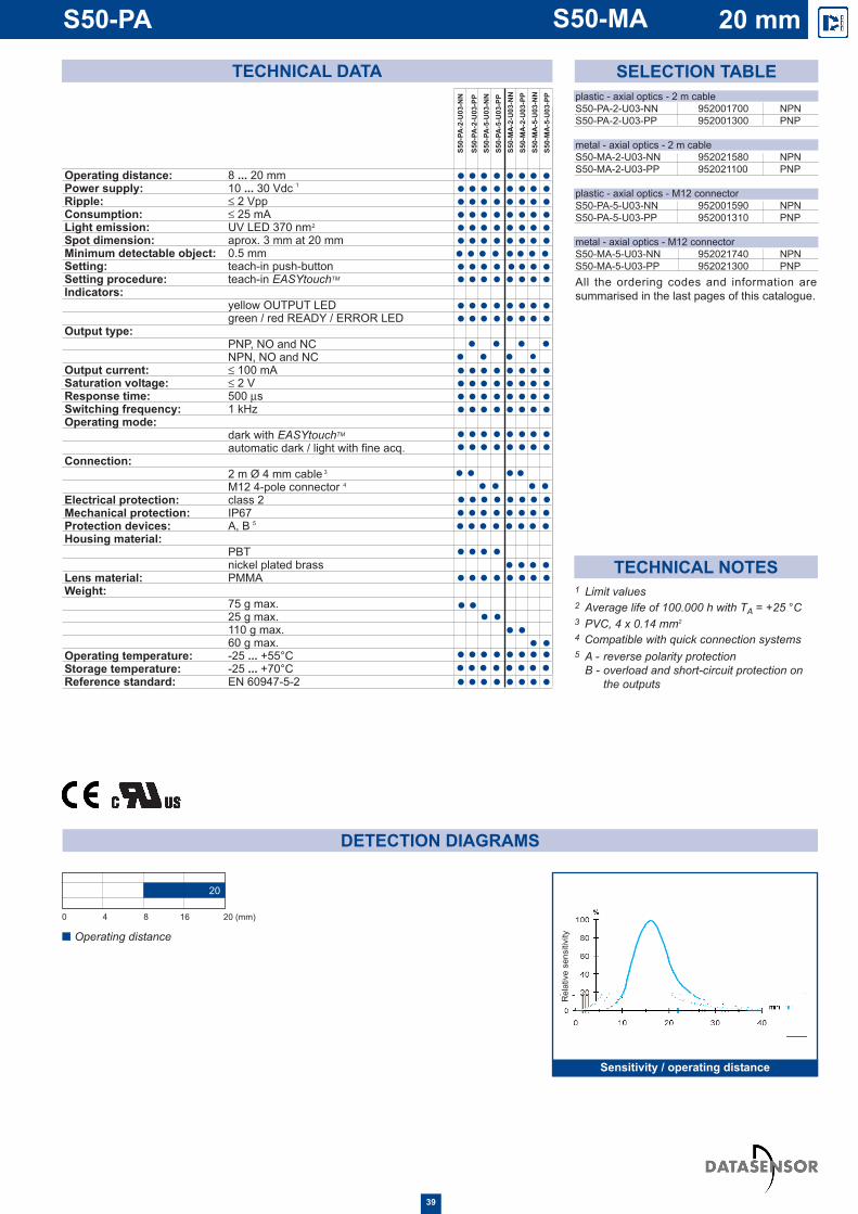
LUMINESCENCE SENSOR WITH UV EMISSION The UV light LED emission detectsany luminescent reference, evenon very reflective surfaces, such asceramics, metal or mirrored glass.The EASYtouch TM se t t ingprocedures fixes automatically thebest detection conditions, simplyby pressing the teach-in push-button once, with the luminescentobject present. By pressing theteach-in push-button and holding itdown until the green light on therear of the sensor flashes, with theluminescent object present andthen pressing the button again inthe presence of a luminescentreference you wish to ignore, ahigher level of accuracy isobtained.
DIMENSIONS
For dedicated accessories refer to theACCESSORIES section of this catalogue.
Refer also to Fibre-optics (A.02), Connectors(A.03) and Fixing brackets (A.04) of theGeneral Catalogue.
INDICA15.5.7iRS AND SETTINGS
T t e a c h - i n b u t t o n f F o r ( s e t t i n . e ) ] T J / T 3 2 1 T f 0 - 1 2 0 T D ( E A S Y t o u c h ) T j / T T 2 1 T f 6 5 . 1 8 4 3 0 T D 0 1 0 7 9 8 T w [ ™ e p o v i d i e s t w o r ( s e t t i n m o d i e : s a t ) 1 4 1 ( a n a r d l o r f a i n , . ) ] T J 6 5 . 1 8 4 3 - 1 2 0 T D 0 . 0 4 3 8 T w [ b o i t h ( o b t ) 1 4 . 2 ( a i n e ( b y p r e s s i n g t h e p u s h - b u t t o n o n l l y o n c . P l e a s e . ) ] T J T * 8 T w [ ( r e f e r t o i n s t r u e c t i o s m a n u r a l f F o r o p n e r t t i n d e t ) 1 4 . 2 ( a l s s . ) ] T J E T / C s 9 c s 0 . 2 s c n 1 3 8 1 6 5 7 2 6 3 9 . 8 4 3 - 6 5 7 . 3 r e 3 4 4 . 0 7 8 9 8 7 0 . 3 6 8 m c f * B T / T T 1 1 T f 1 2 0 0 1 2 3 9 . 1 7 7 2 6 2 5 3 3 . 6 8 1 T m 1 s c n C O N N E C T S I O N S ) T j E T / C s 8 c s 0 0 0 0 s c n 2 1 7 . 5 8 3 1 5 . 7 4 3 4 1 . 2 5 - 7 9 . 3 8 r e 4 2 7 . 1 4 8 2 5 3 3 . 6 8 1 m e f * B T / T T 2 1 T f 8 0 0 8 2 3 8 2 3 6 2 1 2 8 9 . 1 3 8 T m 0 0 0 1 s c n [ ( V ) 5 5 4 . 2 e r s t i o s ( a n d - o p t i o s : ( r e f e r t o e ) ] T J / T T 1 1 T f 0 3 . 8 5 6 1 0 T D [ M O D E L ) - 2 2 2 6 ( A L P H A B E T D I C L ) - 5 7 9 . [ ( I N E X )
DETECTION DIAGRAMS
TECHNICAL NOTES
SELECTION TABLE
All the ordering codes and information aresummarised in the last pages of this catalogue.
plastic - axial optics - 2 m cable S50-PA-2-U03-NN 952001700 NPNS50-PA-2-U03-PP 952001300 PNP
metal - axial optics - 2 m cable S50-MA-2-U03-NN 952021580 NPNS50-MA-2-U03-PP 952021100 PNP
plastic - axial optics - M12 connector S50-PA-5-U03-NN 952001590 NPNS50-PA-5-U03-PP 952001310 PNP
metal - axial optics - M12 connector S50-MA-5-U03-NN 952021740 NPNS50-MA-5-U03-PP 952021300 PNP
TECHNICAL DATA
Operating distance: 8 ... 20 mmPower supply: 10 ... 30 Vdc Ripple: ≤ 2 Vpp Consumption: ≤ 25 mALight emission: UV LED 370 nmSpot dimension: aprox. 3 mm at 20 mmMinimum detectable object: 0.5 mmSetting: teach-in push-button Setting procedure: teach-in EASYtouchTM
Indicators:yellow OUTPUT LED green / red READY / ERROR LED
Output type:PNP, NO and NCNPN, NO and NC
Output current: ≤ 100 mASaturation voltage: ≤ 2 V Response time: 500 µs Switching frequency: 1 kHz Operating mode:
dark with EASYtouchTM
automatic dark / light with fine acq.Connection:
2 m Ø 4 mm cableM12 4-pole connector
Electrical protection: class 2Mechanical protection: IP67Protection devices: A, BHousing material:
PBTnickel plated brass
Lens material: PMMAWeight:
75 g max. 25 g max. 110 g max.60 g max.
Operating temperature: -25 ... +55°C Storage temperature: -25 ... +70°CReference standard: EN 60947-5-2
S50-
PA-2
-U03
-NN
S50-
PA-2
-U03
-PP
S50-
PA-5
-U03
-NN
S50-
PA-5
-U03
-PP
S50-
MA
-2-U
03-N
NS5
0-M
A-2
-U03
-PP
S50-
MA
-5-U
03-N
NS5
0-M
A-5
-U03
-PP
1
3
5
4
2
2 Average life of 100.000 h with TA = +25 °C3 PVC, 4 x 0.14 mm2
4 Compatible with quick connection systems
1 Limit values
5 A - reverse polarity protection B - overload and short-circuit protection on
the outputs
0 4 8 16 20 (mm)
Operating distance
20
Sensitivity / operating distance
Rel
ativ
e se
nsiti
vity
S50-PA S50-MA 20 mm
39

DISTANCE SENSOR WITH RED EMISSIONThis sensor gives an analogue0-10 Vdc output proportional to anobject's distance from the face ofthe sensor over a distance of100 mm. The light intensity of theyellow indicator LED at the rear ofthe sensor is proportional to theobject's distance, the red LEDturns on when the object is outsidethe measurement field.
DIMENSIONS
ACCESSORIES
For dedicated accessories refer to theACCESSORIES section of this catalogue.
Refer also to Connectors (A.03) and Fixingbrackets (A.04) of the General Catalogue.
CONNECTIONS
S50-XX-5S50-XX-2
OUTPUT status andfield LEDs
M12 connector output
Cable output
Fixing nuts
Fixing gasket
A
C
D
E
F
D
C
E
F
C
INDICATORS AND SETTINGSA
A
Versions and options: refer to MODEL ALPHABETICAL INDEX of this catalogue.
PLASTIC HOUSING
METAL HOUSING
40
Y

3 Direct proportionality (DIR) is activated when white wire is connected to +Vdc;Inverse proportionality (INV) is activated when white wire is connected to 0 V.The white wire must always be connected.
DETECTION DIAGRAMS
TECHNICAL NOTES
TECHNICAL DATA
Operating distance: 5 ... 10 cmPower supply: 10 ... 30 Vdc Ripple: ≤ 2 Vpp Consumption: ≤ 30 mALight emission: red LED 630 nmSpot dimension: aprox. 8 mm at 10 cmIndicators:
yellow proportional OUTPUT LED red field LED
Output type: analogue with 0 ... 10V voltageOutput resistance: 2 kΩLoad resistance: ≥ 20 kΩResponse time: 3,33 ms Switching frequency: 150 Hz Resolution: 1 mm / 200 mVOperating mode: direct / inverse proportionalityConnection:
2 m Ø 4 mm cableM12 4-pole connector
Electrical protection: class 2Mechanical protection: IP67Protection devices: A, BHousing material:
PBTnickel plated brass
Lens material: PMMAWeight:
75 g max. 25 g max. 110 g max.60 g max.
Operating temperature: -25 ... +55°C Storage temperature: -25 ... +70°CReference standard: EN 60947-5-2
1
6
4
3
5
2
S50-
PA-2
-Y00
-VK
S50-
PA-5
-Y00
-VK
S50-
MA
-2-Y
00-V
K
S50-
MA
-5-Y
00-V
K
SELECTION TABLEplastic - axial optics - 2 m cable
S50-PA-2-Y00-VK 952001340
metal - axial optics - 2 m cableS50-MA-2-Y00-VK 952021120
plastic - axial optics - M12 connectorS50-PA-5-Y00-VK 952001350
metal - axial optics - M12 connectorS50-MA-5-Y00-VK 952021320
All the ordering codes and information aresummarised in the last pages of this catalogue.
2 Average life of 100.000 h with TA = +25 °C
1 Limit values
4 PVC, 4 x 0.14 mm2
5 Compatible with quick connection systems 6 A - reverse polarity protection
B - overload and short-circuit protection on the outputs
0 2 4 6 8 10 (cm)
Operating distance
10
Measurement field ininverse proportionality
Measurement field indirect proportionality
Direct proportionality (DIR)
Tens
ion
(V)
Tens
ion
(V)
Inverse proportionality (INV)
S50-PA 10 cmS50-MA
41

MODEL DESCRIPTION ORDER N°ST-5010 M18/14 fixing bracket 95ACC5230ST-5011 M18 fixing bracket 95ACC5240ST-5012 M18 fixing bracket 95ACC5250ST-5017 M18 fixing bracket 95ACC5270SP-5037 bracket holder for 6x6 standard profile 95ACC5280SP-5038 bracket holder for 8x8 standard profile 95ACC5290S50 EASY-IN M18/14 EASYin™ adjustable fixing support 95ACC5300JOINT-18 M18 jointed support 95ACC5220SWING-18 adjustable support for plastic tubular M18 sensors 895000006MICRO-18 support with micrometric regulation for tubular M18 sensors 95ACC1380SP-40 fixed support for tubular M18 sensors 9ACC1370MEK-PROOF front protection G5000001Refer also to Accessories for Sensors of the General Catalogue
TECHNOLOGY
The series is compatible with all the Datasensor accessories already developed fortubular sensors. In the General Catalogue refer to:- CS connectors - R reflectors- OF fibre-optics - ST fixing brackets New accessories dedicated to the S50 series have been developed to cover all thefixing requirements and to improve the functioning.In particular EASYin™ is an innovative fixing system that can be used only for theplastic flat version, that allows a fast and safe positioning of the sensor, facilitating theadjustment as well as the locking and unlocking.
1
2
3
4
5
Housing and fixing nuts in indeformable plasticproviding excellent resistance against hostileenvironments. Indelible laser marking
A modular product developed for the automation ofthe assembling and testing process necessary toguarantee intrinsic quality, repeatability andreliabil i ty. One-piece-flow management forimproved service
6
7
42
1
2
3
4
5
ACCESSORIES
ACCESSORIES SELECTION TABLE AND ORDER INFORMATION
EASYtouch™ is a Datasensor patent-covered technology that allows a rapid and safe setting of micro-controlledsensors equipped with a teach-in push-button. A pressure longer than two seconds of the push-button allows a goodadjustment of the sensitivity threshold. EASYtouch™ is the easiest and fastest calibration procedure available on themarket. The instructions on how to best use EASYtouch™ are given in the product's instruction manual.
Multi-layer fine-line PCB
Chip-size components, integrated circuits in 8bumps flip-chip
Analogue digital ASIC
Power ASIC for antivalent outputs
M12 custom connector compatible with quickconnection systems. The four terminals are cone-shaped to facilitate the direct insertion in the cableconductors (4 x 0,5 mm2)
7
6

DIMENSIONS ACCESSORIES
JOINT-18
UNI-5931 M6 SCREWS
VERTICAL OPTIC AXIS HORIZONTAL OPTIC AXIS
S50 EASYin™
UNI-7687 M3 SCREWS UNI-7687 M3 SCREWS
43

44
DIMENSIONS ACCESSORIES
ST-5010 ST-5011
ST-5017ST-5012
SP-5037 SP-5038

DIMENSIONS ACCESSORIES
MICRO-18 SWING-18
SP-40 MEK PROOF
glass
45
* 2 nuts are included

PLASTIC FLAT HOUSING WITH LASER RADIAL OPTICS MODEL CODE N° OPTIC FUNCTION PAGES50-PH-2-B01-NN 952001950 laser retroreflex 14S50-PH-2-B01-PP 952001940 laser retroreflex 14S50-PH-2-C01-NN 952001990 laser proximity 26S50-PH-2-C01-PP 952001980 laser proximity 26S50-PH-2-F01-NN 952002030 laser receiver 6S50-PH-2-F01-PP 952002020 laser receiver 6S50-PH-2 G00-XG 952002060 laser emitter 6S50-PH-5-B01-NN 952001970 laser retroreflex 14S50-PH-5-B01-PP 952001960 laser retroreflex 14S50-PH-5-C01-NN 952002010 laser proximity 26S50-PH-5-C01-PP 952002000 laser proximity 26S50-PH-5-F01-NN 952002050 laser receiver 6S50-PH-5-F01-PP 952002040 laser receiver 6S50-PH-5-G00-XG 952002070 laser emitter 6
PLASTIC FLAT HOUSING WITH LASER AXIAL OPTICS MODEL CODE N° OPTIC FUNCTION PAGES50-PL-2-B01-NN 952001870 laser retroreflex 14S50-PL-2-B01-PP 952001360 laser retroreflex 14S50-PL-2-C01-NN 952001880 laser proximity 26S50-PL-2-C01-PP 952001380 laser proximity 26S50-PL-2-F01-NN 952001890 laser receiver 6S50-PL-2-F01-PP 952001400 laser receiver 6S50-PL-2 G00-XG 952001420 laser emitter 6S50-PL-5-B01-NN 952001840 laser retroreflex 14S50-PL-5-B01-PP 952001370 laser retroreflex 14S50-PL-5-C01-NN 952001850 laser proximity 26S50-PL-5-C01-PP 952001390 laser proximity 26S50-PL-5-F01-NN 952001860 laser receiver 6S50-PL-5-F01-PP 952001410 laser receiver 6S50-PL-5-G00-XG 952001430 laser emitter 6
PLASTIC FLAT HOUSING WITH RADIAL OPTICSMODEL CODE N° OPTIC FUNCTION PAGES50-PR-2-B01-NN 952001780 polarised retroreflex 12S50-PR-2-B01-PP 952001030 polarised retroreflex 12S50-PR-2-C01-NN 952001790 long diffuse proximity 22S50-PR-2-C01-PP 952001070 long diffuse proximity 22S50-PR-2-C10-NN 952001800 short diffuse proximity 18S50-PR-2-C10-PP 952001490 short diffuse proximity 18S50-PR-2-D00-NN 952001810 fixed focus proximity 24S50-PR-2-D00-PP 952001110 fixed focus proximity 24S50-PR-2-F01-NN 952001820 receiver 2S50-PR-2-F01-PP 952001170 receiver 2S50-PR-2-G00-XG 952001210 emitter 2S50-PR-2-T01-NN 952001830 retroreflex for transparents 16S50-PR-2-T01-PP 952001280 retroreflex for transparents 16S50-PR-5-B01-NN 952001720 polarised retroreflex 12S50-PR-5-B01-PP 952001040 polarised retroreflex 12S50-PR-5-C01-NN 952001730 long diffuse proximity 22S50-PR-5-C01-PP 952001080 long diffuse proximity 22S50-PR-5-C10-NN 952001740 short diffuse proximity 18S50-PR-5-C10-PP 952001480 short diffuse proximity 18S50-PR-5-D00-NN 952001750 fixed focus proximity 24S50-PR-5-D00-PP 952001120 fixed focus proximity 24S50-PR-5-F01-NN 952001760 receiver 2S50-PR-5-F01-PP 952001180 receiver 2S50-PR-5-G00-XG 952001220 emitter 2S50-PR-5-T01-NN 952001770 retroreflex for transparents 16S50-PR-5-T01-PP 952001290 retroreflex for transparents 16
PLASTIC FLAT HOUSING WITH AXIAL OPTICS MODEL CODE N° OPTIC FUNCTION PAGES50-PA-2-A00-NN 952002090 retroreflex 10S50-PA-2-A00-PP 952002080 retroreflex 10S50-PA-2-B01-NN 952001610 polarised retroreflex 12S50-PA-2-B01-PP 952001010 polarised retroreflex 12S50-PA-2-C01-NN 952001620 long diffuse proximity 22S50-PA-2-C01-PP 952001050 long diffuse proximity 22S50-PA-2-C10-NN 952001630 short diffuse proximity 18S50-PA-2-C10-PP 952001240 short diffuse proximity 18S50-PA-2-C21-NN 952002170 midi diffuse proximity 20S50-PA-2-C21-PP 952002160 midi diffuse proximity 20S50-PA-2-D00-NN 952001640 fixed focus proximity 24S50-PA-2-D00-PP 952001090 fixed focus proximity 24S50-PA-2-E01-NN 952001650 fibre-optic amplifier 34S50-PA-2-E01-PP 952001130 fibre-optic amplifier 34S50-PA-2-F01-NN 952001660 receiver 2S50-PA-2-F01-PP 952001150 receiver 2S50-PA-2-G00-XG 952001190 emitter 2S50-PA-2-M03-NN 952001670 background suppression 28S50-PA-2-M03-PP 952001230 background suppression 28S50-PA-2-N03-NN 952001680 fore-background suppression 32S50-PA-2-N03-PP 952001440 fore-background suppression 32S50-PA-2-T01-NN 952001690 retroreflex for transparents 16S50-PA-2-T01-PP 952001260 retroreflex for transparents 16S50-PA-2-U03-NN 952001700 luminescence sensor 38S50-PA-2-U03-PP 952001300 luminescence sensor 38S50-PA-2-W03-NN 952001710 contrast sensor 36S50-PA-2-W03-PP 952001320 contrast sensor 36S50-PA-2-Y00-VK 952001340 distance sensor 40S50-PA-5-A00-NN 952002110 retroreflex 10S50-PA-5-A00-PP 952002100 retroreflex 10S50-PA-5-B01-NN 952001500 polarised retroreflex 12S50-PA-5-B01-PP 952001020 polarised retroreflex 12S50-PA-5-C01-NN 952001510 long diffuse proximity 22S50-PA-5-C01-PP 952001060 long diffuse proximity 22S50-PA-5-C10-NN 952001520 short diffuse proximity 18S50-PA-5-C10-PP 952001250 short diffuse proximity 18S50-PA-5-C21-NN 952002190 midi diffuse proximity 20S50-PA-5-C21-PP 952002180 midi diffuse proximity 20S50-PA-5-D00-NN 952001530 fixed focus proximity 24S50-PA-5-D00-PP 952001100 fixed focus proximity 24S50-PA-5-E01-NN 952001540 fibre-optic amplifier 34S50-PA-5-E01-PP 952001140 fibre-optic amplifier 34S50-PA-5-F01-NN 952001550 receiver 2S50-PA-5-F01-PP 952001160 receiver 2S50-PA-5-G00-XG 952001200 emitter 2S50-PA-5-M03-NN 952001560 background suppression 28S50-PA-5-M03-PP 952001000 background suppression 28S50-PA-5-N03-NN 952001570 fore-background suppression 32S50-PA-5-N03-PP 952001450 fore-background suppression 32S50-PA-5-T01-NN 952001580 retroreflex for transparents 16S50-PA-5-T01-PP 952001270 retroreflex for transparents 16S50-PA-5-U03-NN 952001590 luminescence sensor 38S50-PA-5-U03-PP 952001310 luminescence sensor 38S50-PA-5-W03-NN 952001600 contrast sensor 36S50-PA-5-W03-PP 952001330 contrast sensor 36S50-PA-5-Y00-VK 952001350 distance sensor 40
PLASTIC FLAT HOUSING WITH LATERAL OPTICSMODEL CODE N° OPTIC FUNCTION PAGES50-PS-2-M03-NN 952001900 background suppression 30S50-PS-2-M03-PP 952001910 background suppression 30S50-PS-5-M03-NN 952001920 background suppression 30S50-PS-5-M03-PP 952001930 background suppression 30
MODEL ALPHABETICAL INDEX
46

METAL CYLINDRICAL HOUSING WITH LASER AXIAL OPTICSMODEL CODE N° OPTIC FUNCTION PAGES50-ML-2-B01-NN 952021820 laser retroreflex 14S50-ML-2-B01-PP 952021400 laser retroreflex 14S50-ML-2-C01-NN 952021830 laser proximity 26S50-ML-2-C01-PP 952021410 laser proximity 26S50-ML-2-F01-NN 952021840 laser receiver 8S50-ML-2-F01-PP 952021420 laser receiver 8S50-ML-2-G00-XG 952021430 laser emitter 8S50-ML-5-B01-NN 952021850 laser retroreflex 14S50-ML-5-B01-PP 952021440 laser retroreflex 14S50-ML-5-C01-NN 952021860 laser proximity 26S50-ML-5-C01-PP 952021450 laser proximity 26S50-ML-5-F01-NN 952021870 laser receiver 8S50-ML-5-F01-PP 952021460 laser receiver 8S50-ML-5-G00-XG 952021470 laser emitter 8
METAL CYLINDRICAL HOUSING WITH RADIAL OPTICSMODEL CODE N° OPTIC FUNCTION PAGES50-MR-2-B01-NN 952021600 polarised retroreflex 12S50-MR-2-B01-PP 952021140 polarised retroreflex 12S50-MR-2-C01-NN 952021610 long diffuse proximity 22S50-MR-2-C01-PP 952021150 long diffuse proximity 22S50-MR-2-C10-NN 952021620 short diffuse proximity 18S50-MR-2-C10-PP 952021490 short diffuse proximity 18S50-MR-2-D00-NN 952021630 fixed focus proximity 24S50-MR-2-D00-PP 952021160 fixed focus proximity 24S50-MR-2-F01-NN 952021640 receiver 4S50-MR-2-F01-PP 952021170 receiver 4S50-MR-2-G00-XG 952021180 emitter 4S50-MR-2-T01-NN 952021650 retroreflex for transparents 16S50-MR-2-T01-PP 952021190 retroreflex for transparents 16S50-MR-5-B01-NN 952021760 polarised retroreflex 12S50-MR-5-B01-PP 952021340 polarised retroreflex 12S50-MR-5-C01-NN 952021770 long diffuse proximity 22S50-MR-5-C01-PP 952021350 long diffuse proximity 22S50-MR-5-C10-NN 952021780 short diffuse proximity 18S50-MR-5-C10-PP 952021480 short diffuse proximity 18S50-MR-5-D00-NN 952021790 fixed focus proximity 24S50-MR-5-D00-PP 952021360 fixed focus proximity 24S50-MR-5-F01-NN 952021800 receiver 4S50-MR-5-F01-PP 952021370 receiver 4S50-MR-5-G00-XG 952021380 emitter 4S50-MR-5-T01-NN 952021810 retroreflex for transparents 16S50-MR-5-T01-PP 952021390 retroreflex for transparents 16
METAL CYLINDRICAL HOUSING WITH AXIAL OPTICS MODEL CODE N° OPTIC FUNCTION PAGES50-MA-2-A00-NN 952022080 retroreflex 10S50-MA-2-A00-PP 952022090 retroreflex 10S50-MA-2-B01-NN 952021500 polarised retroreflex 12S50-MA-2-B01-PP 952021000 polarised retroreflex 12S50-MA-2-C01-NN 952021510 long diffuse proximity 22S50-MA-2-C01-PP 952021010 long diffuse proximity 22S50-MA-2-C10-NN 952021520 short diffuse proximity 18S50-MA-2-C10-PP 952021020 short diffuse proximity 18S50-MA-2-C21-NN 952022130 midi diffuse proximity 20S50-MA-2-C21-PP 952022120 midi diffuse proximity 20S50-MA-2-D00-NN 952021530 fixed focus proximity 24S50-MA-2-D00-PP 952021030 fixed focus proximity 24S50-MA-2-E01-NN 952021880 fibre-optic amplifier 34S50-MA-2-E01-PP 952021040 fibre-optic amplifier 34S50-MA-2-F01-NN 952021540 receiver 4S50-MA-2-F01-PP 952021050 receiver 4S50-MA-2-G00-XG 952021060 emitter 4S50-MA-2-M03-NN 952021550 background suppression 28S50-MA-2-M03-PP 952021070 background suppression 28S50-MA-2-N03-NN 952021560 fore-background suppression 32S50-MA-2-N03-PP 952021080 fore-background suppression 32S50-MA-2-T01-NN 952021570 retroreflex for transparents 16S50-MA-2-T01-PP 952021090 retroreflex for transparents 16S50-MA-2-U03-NN 952021580 luminescence sensor 38S50-MA-2-U03-PP 952021100 luminescence sensor 38S50-MA-2-W03-NN 952021590 contrast sensor 36S50-MA-2-W03-PP 952021110 contrast sensor 36S50-MA-2-Y00-VK 952021120 distance sensor 40S50-MA-5-A00-NN 952022110 retroreflex 10S50-MA-5-A00-PP 952022100 retroreflex 10S50-MA-5-B01-NN 952021660 polarised retroreflex 12S50-MA-5-B01-PP 952021200 polarised retroreflex 12S50-MA-5-C01-NN 952021670 long diffuse proximity 22S50-MA-5-C01-PP 952021210 long diffuse proximity 22S50-MA-5-C10-NN 952021680 short diffuse proximity 18S50-MA-5-C10-PP 952021220 short diffuse proximity 18S50-MA-5-C21-NN 952022150 midi diffuse proximity 20S50-MA-5-C21-PP 952022140 midi diffuse proximity 20S50-MA-5-D00-NN 952021690 fixed focus proximity 24S50-MA-5-D00-PP 952021230 fixed focus proximity 24S50-MA-5-E01-NN 952021890 fibre-optic amplifier 34S50-MA-5-E01-PP 952021240 fibre-optic amplifier 34S50-MA-5-F01-NN 952021700 receiver 4S50-MA-5-F01-PP 952021250 receiver 4S50-MA-5-G00-XG 952021260 emitter 4S50-MA-5-M03-NN 952021710 background suppression 28S50-MA-5-M03-PP 952021270 background suppression 28S50-MA-5-N03-NN 952021720 fore-background suppression 32S50-MA-5-N03-PP 952021280 fore-background suppression 32S50-MA-5-T01-NN 952021730 retroreflex for transparents 16S50-MA-5-T01-PP 952021290 retroreflex for transparents 16S50-MA-5-U03-NN 952021740 luminescence sensor 38S50-MA-5-U03-PP 952021300 luminescence sensor 38S50-MA-5-W03-NN 952021750 contrast sensor 36S50-MA-5-W03-PP 952021310 contrast sensor 36S50-MA-5-Y00-VK 952021320 distance sensor 40
METAL CYLINDRICAL HOUSING WITH LASER RADIAL OPTICSMODEL CODE N° OPTIC FUNCTION PAGES50-MH-2-B01-NN 952021970 laser retroreflex 14S50-MH-2-B01-PP 952021960 laser retroreflex 14S50-MH-2-C01-NN 952022010 laser proximity 26S50-MH-2-C01-PP 952022000 laser proximity 26S50-MH-2-F01-NN 952022030 laser receiver 8S50-MH-2-F01-PP 952022020 laser receiver 8S50-MH-2-G00-XG 952022060 laser emitter 8S50-MH-5-B01-NN 952021970 laser retroreflex 14S50-MH-5-B01-PP 952021960 laser retroreflex 14S50-MH-5-C01-NN 952022010 laser proximity 26S50-MH-5-C01-PP 952022000 laser proximity 26S50-MH-5-F01-NN 952022050 laser receiver 8S50-MH-5-F01-PP 952022040 laser receiver 8S50-MH-5-G00-XG 952022070 laser emitter 8
METAL CYLINDRICAL HOUSING WITH LATERAL OPTICSMODEL CODE N° OPTIC FUNCTION PAGES50-MS-2-M03-NN 952021900 background suppression 30S50-MS-2-M03-PP 952021910 background suppression 30S50-MS-5-M03-NN 952021920 background suppression 30S50-MS-5-M03-PP 952021930 background suppression 30
47
MODEL ALPHABETICAL INDEX

S 5 0 - P A - 2 - B 0 1 - N N
MODEL CODING TABLE
HEADQUARTERS
DATASENSOR SpAvia Lavino, 265 - 40050 Monte San Pietro, BO - ItalyTel. +39 051/6765611 • Fax +39 051/6759324 www.datasensor.com • e-mail [email protected]
UN
IVER
SAL
TUB
ULA
R S
ENSO
RS
Datasensor SpA endeavours to continuously improve and renew its products; for this reason thetechnical data and contents of this catalogue may undergo variations without prior notice. For correctinstallation and use Datasensor SpA can guarantee only the data indicated in the instruction manualsupplied with the products. 9C
5001
17E
- P
rinte
d in
Ital
y in
May
200
2
Rev
. 01
UNI EN ISO9001 UNI EN ISO14000
Distributed by:
HOUSING P = plastic flatM = metal cylindrical
OPTICSA = axialH = laser radialL = laser axial R = radialS = lateral
CONNECTION2 = cable5 = M12 connector
OPTIC FUNCTION refer to MODELALPHABETICALINDEX
SETTING0 = fixed1 = trimmer 3 = teach-in
push-button
INPUTS / OUTPUTS NN = NPN NO-NC outputsPP = PNP NO-NC outputsXG = no output - test inputVK = 0 - 10 Vdc output with
dir/inv sel. input