Unified Propulsion System to Explore Near-Earth Asteroids ...
8
KOIZUMI 1 28 th Annual AIAA/USU Conference on Small Satellites SSC14-VI-6 Unified Propulsion System to Explore Near-Earth Asteroids by a 50 kg Spacecraft Hiroyuki KOIZUMI Research Center for Advanced Science and Technology, The University of Tokyo, Japan Faculty of Engineering Bldg.7, 7-3-1 Hongo, Bunkyo-ku, Tokyo 113-8656 JAPAN; +81-3-5841-1838 [email protected] Tadashi INAGAKI, Yusuke KASAGI, Taro NAOI, Tomoyuki HAYASHI, Ryu FUNASE Department of Aeronautics and Astronautics, The University of Tokyo, Japan Faculty of Engineering Bldg.7, 7-3-1 Hongo, Bunkyo-ku, Tokyo 113-8656 JAPAN; +81-3-5841-6586 [email protected] Kimiya KOMURASAKI Department of Advanced Energy, The University of Tokyo, Japan 5-1-5, Kashiwanoha , Kashiwa 277-8561; +81-4-7136-3829 [email protected] ABSTRACT In this study, the micropropulsion system I-COUPS (Ion Thruster and COld-gas Thruster Unified Propulsion System) is proposed for 50-kg-class spacecraft to explore the deep space. The I-COUPS is a unified propulsion system of ion thrusters and cold-gas thrusters by sharing the same xenon gas system. It provides the spacecraft with high ΔV maneuver, high thrust, short time maneuver, and reaction control by eight thrusters. The total wet mass of the propulsion system is expected to 9.5 kg with 2.5 kg xenon. The ion thruster has thrust of 300 μN and specific impulse of 1000 s by 35 W power consumption, and the cold-gas thruster has thrust of 30 mN and specific impulse of 24 s by 8 W power. Up to date, structural and thermal model of the I-COUPS finished the developments and environmental tests successfully, and its flight model is under developments and operations. The I-COUPS intended to be installed on the 70 kg spacecraft PROCYON, small space spacecraft to explore near-Earth asteroids by using a micropropulsion system. Its launch is scheduled at the end of 2014 as a small secondary payload by an H-IIA launch vehicle. INTRDUCTION Development and utilization of small satellites are continuing to grow up in the world. Concepts reducing the barrier to entry space development by small satellites have been verified in the 2000s, and eventually practical and commercial utilizations have emerged in the 2010s. Currently most of space missions using small satellites have been remote sensing in LEO. This is because it is the mission strongly related to our lives the most, and therefore commercial applications. From another point of view, however, this is because the capability of the small satellites is limited to remote sensing in LEO. To explore further possibilities by small satellites, wide varieties of space missions need to be realized. Nevertheless, there are a lot of difficulties for this, such as communications, power generation, thermal management, radiation tolerant, and launch chances. Among those difficulties, lack of a propulsion system has greatly limited the activity of the satellites. Most of current small satellites have not installed a propulsion system and they could not control their orbits. Developing a small propulsion system suitable for small satellites can drastically enlarge the available missions[1]. Especially, propulsion with high ΔV ability will remove a number of limitations been charged to small satellites so far. The University of Tokyo has started to develop the new micropropulsion system I-COUPS (Ion Thruster and COld-gas Thruster Unified Propulsion System) for the first step of pioneering in novel missions of small spacecraft. The I-COUPS is a unified propulsion system of ion thrusters [2] and cold-gas thrusters by sharing the same gas system. Combination of electric and chemical propulsion provides the spacecraft with both high ΔV maneuver and high thrust, short time maneuver. Additionally, extremely simple structure of cold-gas thrusters and sharing the same gas system with ion thruster realize very light weight and compact reaction control system suitable for small spacecraft.
Transcript of Unified Propulsion System to Explore Near-Earth Asteroids ...

KOIZUMI 1 28th
Annual AIAA/USU
Conference on Small Satellites
SSC14-VI-6
Unified Propulsion System to Explore Near-Earth Asteroids by a 50 kg Spacecraft
Hiroyuki KOIZUMI
Research Center for Advanced Science and Technology, The University of Tokyo, Japan
Faculty of Engineering Bldg.7, 7-3-1 Hongo, Bunkyo-ku, Tokyo 113-8656 JAPAN; +81-3-5841-1838
Tadashi INAGAKI, Yusuke KASAGI, Taro NAOI, Tomoyuki HAYASHI, Ryu FUNASE
Department of Aeronautics and Astronautics, The University of Tokyo, Japan
Faculty of Engineering Bldg.7, 7-3-1 Hongo, Bunkyo-ku, Tokyo 113-8656 JAPAN; +81-3-5841-6586
Kimiya KOMURASAKI
Department of Advanced Energy, The University of Tokyo, Japan
5-1-5, Kashiwanoha , Kashiwa 277-8561; +81-4-7136-3829
ABSTRACT
In this study, the micropropulsion system I-COUPS (Ion Thruster and COld-gas Thruster Unified Propulsion
System) is proposed for 50-kg-class spacecraft to explore the deep space. The I-COUPS is a unified propulsion
system of ion thrusters and cold-gas thrusters by sharing the same xenon gas system. It provides the spacecraft with
high ΔV maneuver, high thrust, short time maneuver, and reaction control by eight thrusters. The total wet mass of
the propulsion system is expected to 9.5 kg with 2.5 kg xenon. The ion thruster has thrust of 300 μN and specific
impulse of 1000 s by 35 W power consumption, and the cold-gas thruster has thrust of 30 mN and specific impulse
of 24 s by 8 W power. Up to date, structural and thermal model of the I-COUPS finished the developments and
environmental tests successfully, and its flight model is under developments and operations. The I-COUPS intended
to be installed on the 70 kg spacecraft PROCYON, small space spacecraft to explore near-Earth asteroids by using a
micropropulsion system. Its launch is scheduled at the end of 2014 as a small secondary payload by an H-IIA launch
vehicle.
INTRDUCTION
Development and utilization of small satellites are
continuing to grow up in the world. Concepts reducing
the barrier to entry space development by small
satellites have been verified in the 2000s, and
eventually practical and commercial utilizations have
emerged in the 2010s. Currently most of space missions
using small satellites have been remote sensing in LEO.
This is because it is the mission strongly related to our
lives the most, and therefore commercial applications.
From another point of view, however, this is because
the capability of the small satellites is limited to remote
sensing in LEO.
To explore further possibilities by small satellites, wide
varieties of space missions need to be realized.
Nevertheless, there are a lot of difficulties for this, such
as communications, power generation, thermal
management, radiation tolerant, and launch chances.
Among those difficulties, lack of a propulsion system
has greatly limited the activity of the satellites. Most of
current small satellites have not installed a propulsion
system and they could not control their orbits.
Developing a small propulsion system suitable for small
satellites can drastically enlarge the available
missions[1]. Especially, propulsion with high ΔV
ability will remove a number of limitations been
charged to small satellites so far.
The University of Tokyo has started to develop the new
micropropulsion system I-COUPS (Ion Thruster and
COld-gas Thruster Unified Propulsion System) for the
first step of pioneering in novel missions of small
spacecraft. The I-COUPS is a unified propulsion system
of ion thrusters [2] and cold-gas thrusters by sharing the
same gas system. Combination of electric and chemical
propulsion provides the spacecraft with both high ΔV
maneuver and high thrust, short time maneuver.
Additionally, extremely simple structure of cold-gas
thrusters and sharing the same gas system with ion
thruster realize very light weight and compact reaction
control system suitable for small spacecraft.
KOIZUMI 2 28th
Annual AIAA/USU
Conference on Small Satellites
The I-COUPS is intended to be installed on the 70 kg
spacecraft PROCYON developed by the University of
Tokyo and Japan Space Exploration Agency [3]. The
main purpose of the PROCYON is verification and
demonstration of spacecraft BUS and key technologies
for deep space exploration by 50-kg-class spacecraft.
The final mission target thorough those verifications is
to perform flyby observation of near-Earth asteroids,
and PROCYON is an acronym of PRoximate Object
Close flYby with Optical Navigation. The detail of the
spacecraft will be described in the reference [3].
The PROCYON is potentially the first small space
spacecraft (<100 kg) to explore near-Earth asteroids by
using a micropropulsion system. The launch of
PROCYON is currently scheduled at the end of 2014 as
a small secondary payload by an H-IIA launch vehicle
along with the main payload HAYABUSA-2. Up to
date, structural and thermal model of the spacecraft has
been developed including the new propulsion system.
Currently, the flight model is under development
toward the completion of all of the tests by the end of
this summer.
I-COUPS
Three propulsion capabilities are required for I-COUPS
to realize the fly-by observation of small asteroids: 1)
reaction control for wheel unloading, 2) high delta-V
for the Earth gravity assist, and 3) high thrust for
trajectory correction maneuver.
1) Spacecraft in planetary orbit have to install a reaction
control system by thrusters. In general, disturbance
torques due to solar pressure, atmospheric drag, and
misaligned thrust vector change the angular momentum
of spacecraft. The momentum is temporally
accumulated into reaction wheels of the spacecraft, and
is eventually released to the outside before the
saturation. In the case of small/micro-satellites in LEO,
that release, called as “unloading”, is conducted by
using magnetic torques rather than thrusters as
standard-sized spacecraft. However, spacecraft in
planetary orbits cannot use the magnetic torques and
have to install thrusters for it.
2) One year after the launch and orbit insertion, the
spacecraft is performing Earth-gravity assist to change
its trajectory toward the asteroid. The re-gathering with
Earth requires an orbit transfer with a delta-V of 30 to
100 m/s or more. The exact value of that delta-V
depends on the orbit insertion of the main payload, and
a secondary payload needs to prepare delta-V as high as
possible to fit to various cases.
3) In the final phase, proximity operation mission of the
asteroid, the spacecraft has to correct its trajectory
within a limited period to fly by the asteroid as close as
possible. This period is estimated to a few days, and it
requires more than 10 mN of thrust.
To achieve the above-mentioned three propulsion
capabilities in the constraints of a 50-kg-class
spacecraft, a propulsion system which unifies an ion
thruster and multiple cold-gas thrusters are proposed
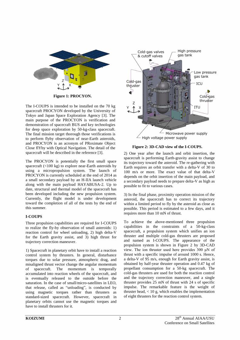
and named as I-COUPS. The appearance of the
propulsion system is shown in Figure 2 by 3D-CAD
view. The ion thruster used here provides 300 μN of
thrust with a specific impulse of around 1000 s. Hence,
a delta-V of 95 m/s, enough for Earth gravity assist, is
obtained by half-year thruster operation and 0.47 kg of
propellant consumption for a 50-kg spacecraft. The
cold-gas thrusters are used for both the reaction control
and the trajectory correction maneuver, and a single
thruster provides 25 mN of thrust with 24 s of specific
impulse. The remarkable feature is the weight of
thruster head, < 10 g, which enables the implementation
of eight thrusters for the reaction control system.
Figure 1: PROCYON.
Figure 2: 3D-CAD view of the I-COUPS.
X
Z
Y
X
Z
Y
High voltage power supply
Microwave power supply
ITU
ICU
Low pressuregas tank
Cold-gas valves& cutoff valves
High pressuregas tank
Cold-gasthruster
Cold-gasthruster
KOIZUMI 3 28th
Annual AIAA/USU
Conference on Small Satellites
The I-COUPS consists of five units: an ion-thruster unit
(ITU), a cold gas thruster unit (CTU), a power-
processing unit (PPU), a gas-management unit (GMU),
and a I-COUPS control unit (ICU). A simplified block
diagram of the system is given in the Figure 3. The
components and structure of I-COUPS are based on the
miniature ion propulsion system: MIPS [4-6], which
was developed for the 60-kg, LEO-satellite
HODOYOSHI-4 [7-9]. The essential difference from
the MIPS is the addition of CTU whose gas is extracted
from the xenon GMU. The details of the gas system are
described in the next section. The controller ICU
implemented an additional board to handle newly added
12 valves, where eight are thruster valves and four are
for the redundancy. ITU and PPU have no difference
from the units installed as MIPS.
DETAILS OF THE UNITS
GMU: Gas Management Unit
A gas management unit, GMU, controls the xenon flow
rate by a “bang-bang control”. Pressurized xenon is
stored in a CFRP/GFRP tank (Teijin, ALT764J). The
capacity of the tank is 2.0 L, its dry mass is 1.00 kg, and
the service pressure is 19.6 MPa. The nominal charging
pressure of the I-COUPS was set to 7.75 MPa at 30 °C.
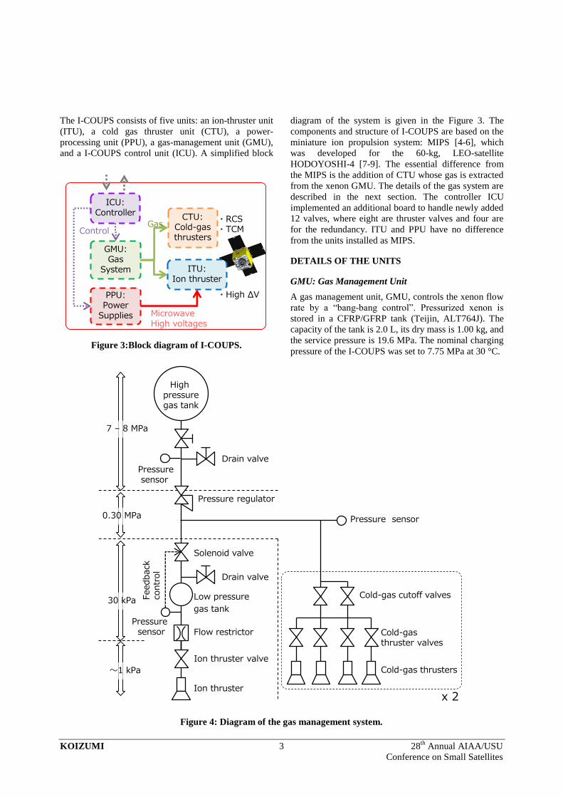
Figure 3:Block diagram of I-COUPS.
Figure 4: Diagram of the gas management system.
GMU:Gas
System ITU:Ion thruster
CTU:Cold-gasthrusters
ICU:Controller
ControlGas
PPU:Power
Supplies MicrowaveHigh voltages
・RCS・TCM
・High ΔV
Pressure regulator
Drain valve
Low pressure
gas tank
Pressure sensor
Ion thruster valve
Flow restrictor
7 – 8 MPa
0.30 MPa
30 kPa
~1 kPa
Ion thruster
Highpressuregas tank
Solenoid valve
Feedback
contr
ol
Drain valve
Pressuresensor
Cold-gas thrusters
Cold-gas thruster valves
Cold-gas cutoff valves
x 2
Pressure sensor
KOIZUMI 4 28th
Annual AIAA/USU
Conference on Small Satellites
The GMU has a two-staged pressure regulation to
provide two different mass flow rates for an ion thruster
and cold-gas thrusters. The system diagram of the GMU
is shown in the Figure 4. Firstly, the high pressure gas
( 8 MPa) is regulated down to 0.30 MPa by a pre-fixed
mechanical pressure regulator. The gas line is divided
to the ITU and CTU at this pressure. In the ITU, 0.30
MPa gas is further regulated down to about 30 kPa
using a solenoid valve and pressure sensor. A low
pressure tank is installed as an accumulator to extend
the control period. The exit of the low pressure tank is
connected to the ITU through a flow restrictor. The
pressure is controlled depending on the required mass
flow rate. In the CTU, 0.30 MPa gas is directly used for
cold gas thrusters.
ICU: I-COUPS Control Unit
An I-COUPS control unit is the only electrical interface
with the spacecraft on-board computer (OBC). The ICU
receives commands from the OBC, to open/close all of
the valves and to switch on/off of the HVPS and MPS.
This control includes the open/close of the solenoid
valve to regulate the pressure at the low pressure tank
for the gas flow to the ITU. All of the analog
telemetries and statuses of the propulsion components
are gathered by the ICU and sent to the OBC after the
electrical isolations and analog-to-digital conversions.
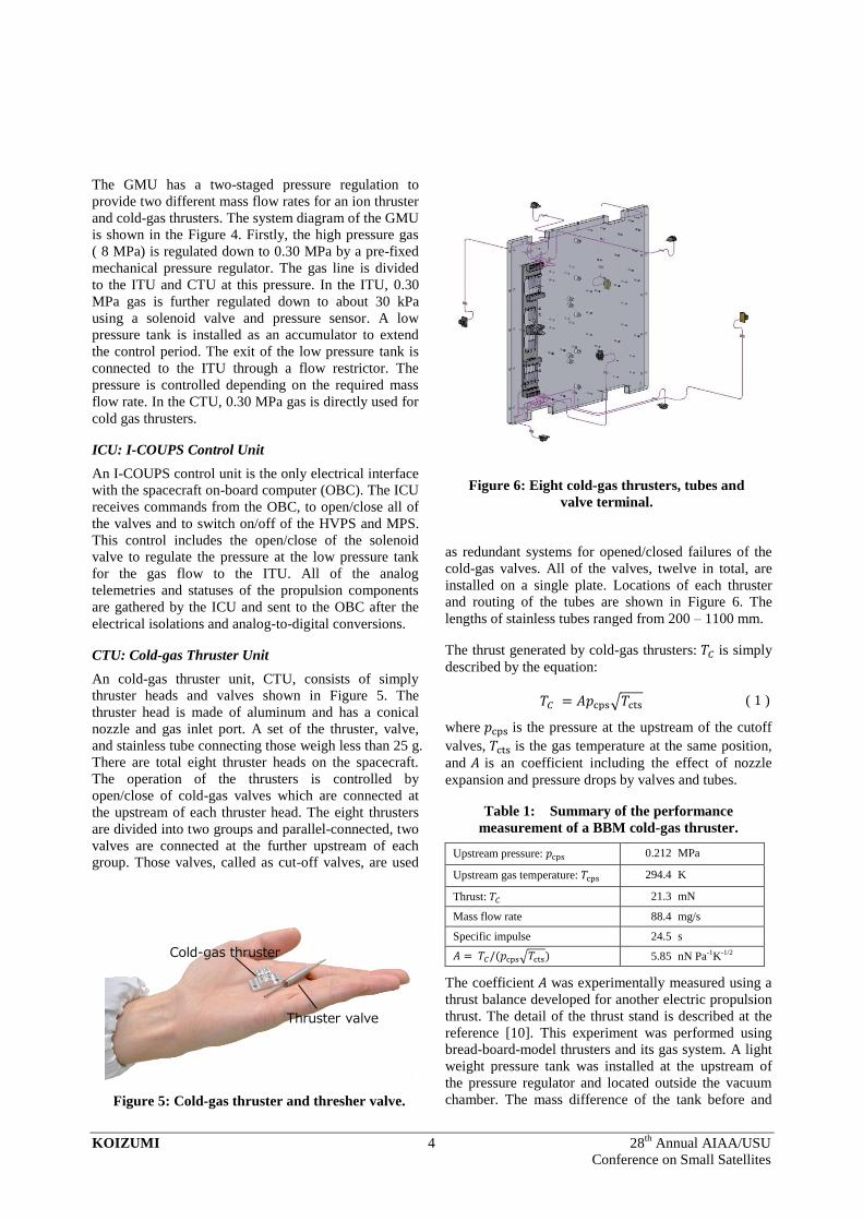
CTU: Cold-gas Thruster Unit
An cold-gas thruster unit, CTU, consists of simply
thruster heads and valves shown in Figure 5. The
thruster head is made of aluminum and has a conical
nozzle and gas inlet port. A set of the thruster, valve,
and stainless tube connecting those weigh less than 25 g.
There are total eight thruster heads on the spacecraft.
The operation of the thrusters is controlled by
open/close of cold-gas valves which are connected at
the upstream of each thruster head. The eight thrusters
are divided into two groups and parallel-connected, two
valves are connected at the further upstream of each
group. Those valves, called as cut-off valves, are used
as redundant systems for opened/closed failures of the
cold-gas valves. All of the valves, twelve in total, are
installed on a single plate. Locations of each thruster
and routing of the tubes are shown in Figure 6. The
lengths of stainless tubes ranged from 200 – 1100 mm.
The thrust generated by cold-gas thrusters: is simply
described by the equation:
√ ( 1 )
where is the pressure at the upstream of the cutoff
valves, is the gas temperature at the same position,
and is an coefficient including the effect of nozzle
expansion and pressure drops by valves and tubes.
Table 1: Summary of the performance
measurement of a BBM cold-gas thruster.
Upstream pressure: 0.212 MPa
Upstream gas temperature: 294.4 K
Thrust: 21.3 mN
Mass flow rate 88.4 mg/s
Specific impulse 24.5 s
√ 5.85 nN Pa-1K-1/2
The coefficient was experimentally measured using a
thrust balance developed for another electric propulsion
thrust. The detail of the thrust stand is described at the
reference [10]. This experiment was performed using
bread-board-model thrusters and its gas system. A light
weight pressure tank was installed at the upstream of
the pressure regulator and located outside the vacuum
chamber. The mass difference of the tank before and
Figure 5: Cold-gas thruster and thresher valve.
Figure 6: Eight cold-gas thrusters, tubes and
valve terminal.
Cold-gas thruster
Thruster valve
KOIZUMI 5 28th
Annual AIAA/USU
Conference on Small Satellites
after the 30-s-operation of the BBM thruster was
measured by a precise balance and averaged mass flow
rate was obtained. The measurements were conducted
with different tube length from 270 to 1000 mm and
with different number of the tube-bending from 2 to 6.
The measured thrust and mass flow rate did not depend
on those parameters. The result was summarized in
Table 1 by averaging the data of the all conditions. In
this experiment, the upstream pressure was set to 0.21 –
0.23 MPa. Flight model, cold-gas thruster is driven by
upstream pressure of 0.30 MPa (setting) and the thrust
of 30 mN is estimated.
ITU: Ion Thruster Unit
An ion thruster unit, ITU, consists of an ion beam
source, a neutralizer, a thruster valve, a gas distributer,
a gas isolator, and DC-blocks. The ion beam source and
the neutralizer have ECR-plasma sources driven by
microwave injection respectively and both sources have
almost identical design. Both plasmas need the same
amount of microwave power, typically 1.0 W each
other. The detail of the discharge chamber was
described in the reference [11-13]. The ion beam source
installs a two-grids system to accelerate and exhaust
ions. The neutralizer installs a four-holed orifice,
instead of the grid system, for electron emission.
Contrasting to the microwave power, lower gas
conductance of the neutralizer orifice causes the half
gas flow rate of the neutralizer compared with the ion
beam source.
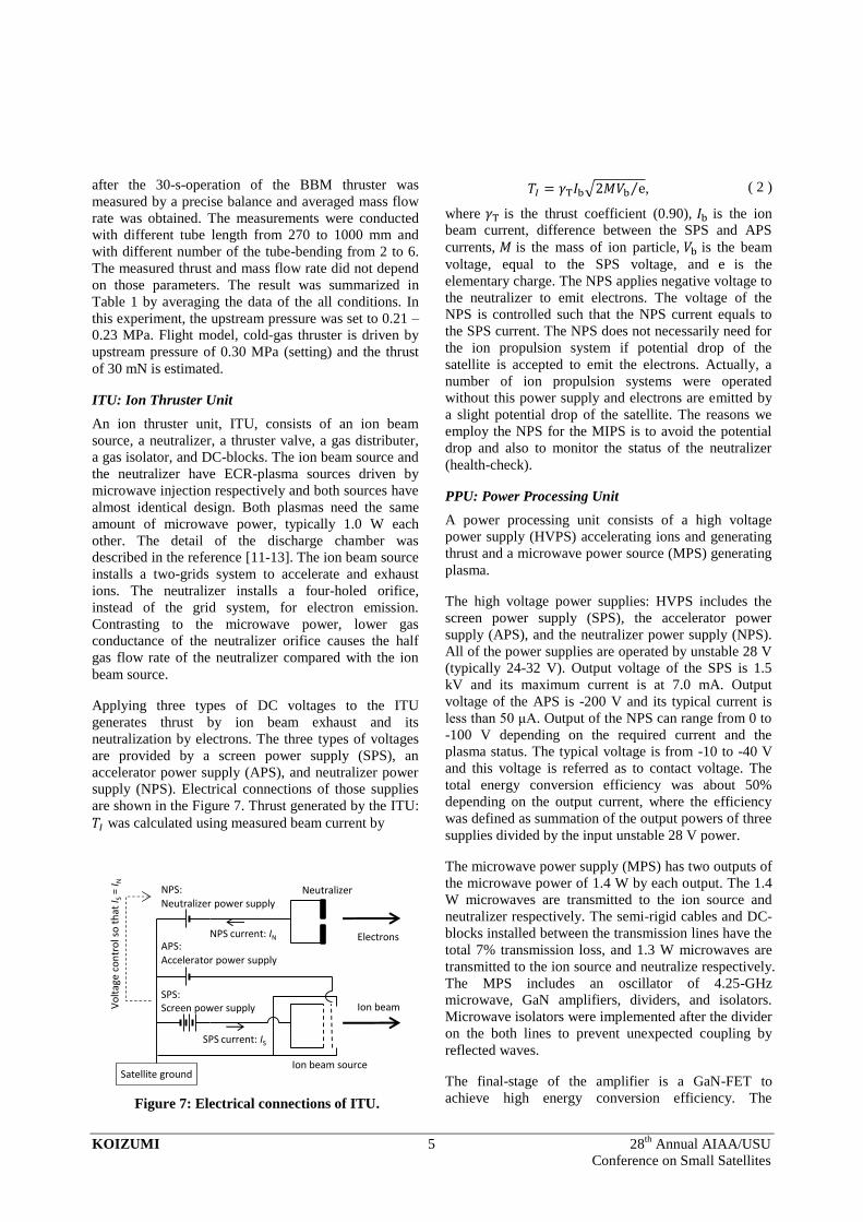
Applying three types of DC voltages to the ITU
generates thrust by ion beam exhaust and its
neutralization by electrons. The three types of voltages
are provided by a screen power supply (SPS), an
accelerator power supply (APS), and neutralizer power
supply (NPS). Electrical connections of those supplies
are shown in the Figure 7. Thrust generated by the ITU:
was calculated using measured beam current by
√ ⁄ , ( 2 )
where is the thrust coefficient (0.90), is the ion
beam current, difference between the SPS and APS
currents, is the mass of ion particle, is the beam
voltage, equal to the SPS voltage, and is the
elementary charge. The NPS applies negative voltage to
the neutralizer to emit electrons. The voltage of the
NPS is controlled such that the NPS current equals to
the SPS current. The NPS does not necessarily need for
the ion propulsion system if potential drop of the
satellite is accepted to emit the electrons. Actually, a
number of ion propulsion systems were operated
without this power supply and electrons are emitted by
a slight potential drop of the satellite. The reasons we
employ the NPS for the MIPS is to avoid the potential
drop and also to monitor the status of the neutralizer
(health-check).
PPU: Power Processing Unit
A power processing unit consists of a high voltage
power supply (HVPS) accelerating ions and generating
thrust and a microwave power source (MPS) generating
plasma.
The high voltage power supplies: HVPS includes the
screen power supply (SPS), the accelerator power
supply (APS), and the neutralizer power supply (NPS).
All of the power supplies are operated by unstable 28 V
(typically 24-32 V). Output voltage of the SPS is 1.5
kV and its maximum current is at 7.0 mA. Output
voltage of the APS is -200 V and its typical current is
less than 50 μA. Output of the NPS can range from 0 to
-100 V depending on the required current and the
plasma status. The typical voltage is from -10 to -40 V
and this voltage is referred as to contact voltage. The
total energy conversion efficiency was about 50%
depending on the output current, where the efficiency
was defined as summation of the output powers of three
supplies divided by the input unstable 28 V power.
The microwave power supply (MPS) has two outputs of
the microwave power of 1.4 W by each output. The 1.4
W microwaves are transmitted to the ion source and
neutralizer respectively. The semi-rigid cables and DC-
blocks installed between the transmission lines have the
total 7% transmission loss, and 1.3 W microwaves are
transmitted to the ion source and neutralize respectively.
The MPS includes an oscillator of 4.25-GHz
microwave, GaN amplifiers, dividers, and isolators.
Microwave isolators were implemented after the divider
on the both lines to prevent unexpected coupling by
reflected waves.
The final-stage of the amplifier is a GaN-FET to
achieve high energy conversion efficiency. The
Figure 7: Electrical connections of ITU.
APS:Accelerator power supply
NPS:Neutralizer power supply
Ion beam
Electrons
Ion beam source
Neutralizer
Vo
ltag
e co
ntr
ol s
o t
hat
I S= I N
SPS:Screen power supply
SPS current: IS
NPS current: IN
Satellite ground
KOIZUMI 6 28th
Annual AIAA/USU
Conference on Small Satellites
conversion efficiency of the MPS-BBM showed the
maximum efficiency of 48% from three DC powers to
the output microwave power (single output). Three DC
voltages are 24 V to the FET drain, -5 V to the FET
gate, and 5.0 V for the oscillator. Flight operation of the
MPS needs to consider more two efficiencies. DC/DC
conversion from unstable 28 V, which is supplied from
the satellite bus, to the regulated those three has typical
efficiency around 70%. Splitting and isolating the
output microwave power has efficiency around 80%.
As a result, the MPS-FM had about 20% of the total
efficiency.
DEVELOPMENT
STM: Structural and Thermal Model
Structure and components of PROCYON and I-COUPS
are based on HODOYOSHI-3/4 and MIPS respectively.
Then development of PROCYON and I-COUPS started
from its structural and thermal model (STM) to check
the differences. The major difference of I-COUPS from
the MIPS is to addition of CTU and modification of
GMU. Cold-gas thrusters and its gas tubes are
completely new developments. The valves used for
CTU are the same as RV and IV of MIPS and have
already cleared required environmental tests. As to the
GMU, the size of high pressure tank increased from 1.1
L of MIPS to 2.0 L of I-COUPS. Then mechanical
structure supporting the tank was newly designed.
Additionally, several modifications were performed to
increase the reliability of the GMU, because it is a
critical component providing reaction controls for the
spacecraft. It is contrast to the HODOYOSHI-4 where
MIPS was installed as mission component and its
failure does not have fatal impact to the satellite.
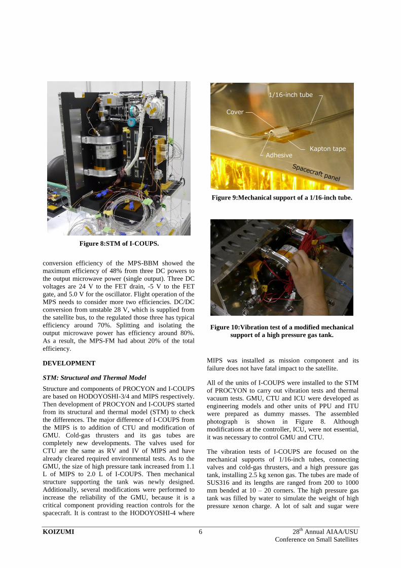
All of the units of I-COUPS were installed to the STM
of PROCYON to carry out vibration tests and thermal
vacuum tests. GMU, CTU and ICU were developed as
engineering models and other units of PPU and ITU
were prepared as dummy masses. The assembled
photograph is shown in Figure 8. Although
modifications at the controller, ICU, were not essential,
it was necessary to control GMU and CTU.
The vibration tests of I-COUPS are focused on the
mechanical supports of 1/16-inch tubes, connecting
valves and cold-gas thrusters, and a high pressure gas
tank, installing 2.5 kg xenon gas. The tubes are made of
SUS316 and its lengths are ranged from 200 to 1000
mm bended at 10 – 20 corners. The high pressure gas
tank was filled by water to simulate the weight of high
pressure xenon charge. A lot of salt and sugar were
Figure 8:STM of I-COUPS.
Figure 9:Mechanical support of a 1/16-inch tube.
Figure 10:Vibration test of a modified mechanical
support of a high pressure gas tank.
Cover
1/16-inch tube
Kapton tapeAdhesive
KOIZUMI 7 28th
Annual AIAA/USU
Conference on Small Satellites
dissolved into the water to increase the density and
match it to that of 7.75 MPa xenon at 30 °C, 1.25 g/cc.
The stainless tubes are fixed on the panel surfaces of
the craft by cover plates and adhesives, as shown in
Figure 9, where two types of adhesives: RTV silicone
rubber and epoxy adhesive are used. As a result of the
vibration tests, several cover plates using RTV fell off
and the others had never fallen, and selected for the
flight model. In addition, screw-clamped fixtures are
added to the flight model to increase the handling
abilities.
Initial design of the tank support could not hold the tank
during all of the vibration tests. In that design, the tank
was bounded toward the corner of two inner panels by
two bands clamping those panels. However, sinusoidal
vibration vertical to the tank axis rotated the tank
around its axis. Deformations of the panels by the
vibration generated gaps between bands and tank to
rotate it. A new supporting structure was proposed for
the flight model, which holds the tank independently on
the panel. The vibration tests of this new support were
conducted as additional tests and there was no tank
rotation between before and after the vibration tests.
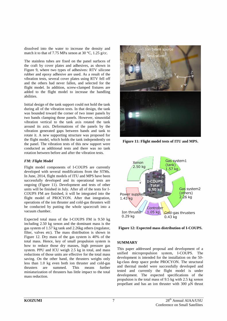
FM: Flight Model
Flight model components of I-COUPS are currently
developed with several modifications from the STMs.
In June, 2014, flight models of ITU and MPS have been
successfully developed and its operational tests are
ongoing (Figure 11). Development and tests of other
units will be finished in July. After all of the tests for I-
COUPS FM are finished, it will be integrated into the
flight model of PROCYON. After that integration,
operations of the ion thruster and cold-gas thrusters will
be conducted by putting the whole spacecraft into a
vacuum chamber.
Expected total mass of the I-COUPS FM is 9.50 kg
including 2.50 kg xenon and the dominant mass is the
gas system of 1.57 kg tank and 2.26kg others (regulator,
filter, valves etc). The mass distribution is shown in
Figure 12. Dry mass of the gas system is 40% of the
total mass. Hence, key of small propulsion system is
how to reduce those dry masses, high pressure gas
system. PPU and ICU weigh 2.5 kg in total, and mass
reductions of those units are effective for the total mass
saving. On the other hand, the thrusters weighs only
less than 1.0 kg even both ion thruster and cold-gas
thrusters are summed. This means further
miniaturization of thrusters has little impact to the total
mass reduction.
SUMMARY
This paper addressed proposal and development of a
unified micropropulsion system, I-COUPS. The
development is intended for the installation on the 50-
kg-class deep space probe PROCYON. The structural
and thermal model were successfully developed and
tested and currently the flight model is under
development. The expected specifications of the
propulsion is the total mass of 9.5 kg with 2.5 kg xenon
propellant and has an ion thruster with 300 μN thrust
Figure 11: Flight model tests of ITU and MPS.
Figure 12: Expected mass distribution of I-COUPS.
X
ZY
Ion beam source
Neutralizer
Gas system1(tank)1.57 kg
Gas system2(others)2.26 kg
Cold-gas thrusters0.43 kg
Controller1.05 kg
Power supplies1.43 kg
Ion thruster0.29 kg
Xenon2.50 kg
KOIZUMI 8 28th
Annual AIAA/USU
Conference on Small Satellites
and 1000 s Isp and eight cold-gas thrusters with 30 mN
thrust and 24 s Isp each.
Acknowledgments
This work was supported by JSPS KAKENHI grant:
Grant-in-Aid for Scientific Research (B), No. 25289304.
The authors would like to express their deepest
gratitude to Mr. Asakawa, Mr. Kawahara, and Mr.
Yaginuma, at Space Propulsion lab in the University of
Tokyo, for a lot of efforts since April 2014 to develop
the flight model of I-COUPS.
References
1. Micci, M. M., and Ketsdever, A. D.,
Micropropulsion for Small Spacecraft, American
Institute of Aeronautics and Astronautics,
Washington, D.C., 2000.
2. Goebel, D.M. and Katz, I., Fundamentals of
Electric Propulsion, Wiley, New Jersey, 2008.
3. Funase, R., Kawakatsu, Y., Fukushima, Y.,
Tomiki, A., Kobayashi, Y., Nakatsuka, J., Mita,
M., and Kobayashi, D., “50kg—Class Deep
Space Exploration Technology Demonstration
Micro—spacecraft PROCYON,” 28th
Annual
AIAA/USU Conference on Small Satellites, Utah
State University, 2-7 August 2014.
4. Koizumi, H. Komurasaki, K., and Arakawa, Y.,
“Development of the Miniature Ion Propulsion
System for 50 kg Small Spacecraft,” 48th
AIAA/ASME/SAE/ASEE Joint Propulsion
Conference & Exhibit, , Atlanta, Georgia, 30 July
- 01 August 2012, AIAA 2012-3949.
5. Koizumi, H. Komurasaki, K., Aoyama, J., and
Yamaguchi, K., “Engineering Model of the
Miniature Ion Propulsion System for the Nano-
satellite,” Trans. JSASS Space Tech. Japan, Vol.
12, pp.Tb_19-Tb_24, 2014.
6. Koizumi, H., Inagaki, T., Naoi, T., Kasagi, Y.,
Komurasaki, K., Aoyama, J., and Yamaguchi, K.,
“Development of the Miniature Ion Propulsion
System: MIPS for the 50-kg-Nano-satellite
HODOYOSHI-4,” Space Propulsion 2014,
Cologne, Germany, 19-22 May 2014.
7. Nakasuka, S., “From Education to Practical Use
of Nano-satellites –Japanese University
Challenge towards Low Cost Space Utilization –,”
8th IAA Symposium on Small Satellites for Earth
Observation, Berlin, April, 2011.
8. Nakasuka, S., “Low Cost Practical Micro/Nano-
Satellites with Reasonably Reliable Systems
"HODOYOSHI" Concept,” The 3rd Aerospace
Innovation Workshop, University of Tokyo,
Japan, 2011.
9. Shiraska, S., Nakasuka, S., “Realization of the
Concept of Reasonably Reliable Systems
Engineering in the Design of Nano-Satellites,”
Trans. Jpn. Soc. Aeronaut. Space Sci., Aerospace
Tech. Jph., 10(2012), pp.7-12.
10. Nagao, N., Yokota, S., Komurasaki, K., Arakawa,
Y., “Development of a Two-dimensional Dual
Pendulum Thrust Stand for Hall Thrusters,”
Review of Scientific Instruments, Vol. 7, 115108,
2007.
11. Koizumi, H. and Kuninaka, H.: Antenna Design
Method for Low Power Miniaturized Microwave
Discharge Ion thrusters, J. JSASS, 57 (2009).
12. Koizumi, H. and Kuninaka, H., “Development of
a Miniature microwave discharge ion thruster
driven by 1 W microwave power,” Journal of
Propulsion and Power, Vol26,No.3, pp.601-604,
2010.
13. Koizumi, H. and Kuninaka, H.: Performance
Evaluation of a Miniature Ion Thruster μ1 with a
Unipolar and Bipolar Operation, International
Electric Propulsion Conference, IEPC-2011-297.
14. Wyatt, C.L., Radiometric Calibration: Theory
and Methods, Academic Press, New York, 1978.


![Propulsion%20system %203rd[1]](https://static.fdocument.pub/doc/165x107/55d52409bb61eb74118b4634/propulsion20system-203rd1.jpg)