
Understanding crystallization processes of NiO/Ce0.9Gd0.1O2−δ sol–gel processed thin films for...
6
Understanding crystallization processes of NiO/Ce 0.9 Gd 0.1 O 2d sol–gel processed thin films for the design of efficient electrodes: an in situ thermal ellipsometry analysis† Guillaume M€ uller, ab C edric Boissi ere, a David Grosso, a Armelle Ringued e, b Christel Laberty-Robert * a and Cl ement Sanchez a Received 12th December 2011, Accepted 7th March 2012 DOI: 10.1039/c2jm16550c We describe a simple, non-destructive method, in situ thermal ellipsometry analysis (TEA), for understanding the different processes (decomposition of organics, crystallization, and sintering) occurring upon heating hybrid organic–inorganic films. According to these studies, a thermal treatment was tailored in order to obtain robust, nanocrystalline inorganic mesoporous 100–150 nm thick films with efficiently connected porosity surrounded by a crystalline inorganic network. Polymodal porous, nanocrystalline NiO/Gd-doped Ceria composites or Ni/Gd-doped Ceria films, interconnected network of open pores ranging from macro- to micro-pores, have been synthesized. The inorganic network is built from connected crystalline nanoparticles with mean diameters of 12 3 nm, whose small size is still preserved even at 800 C. We also show that the thermal ellipsometry analysis is readily extendable to MO/Gd-doped Ceria with M ¼ Cu, Ni, Co, etc., therefore demonstrating the interest of this technique in understanding thermal phenomena in complex ceramic and composite systems. This is trivial for designing electrodes with efficient microstructure. Introduction Mesoporous inorganic films open up a land of opportunity for the design of new materials 1,2 for photonics, 3,4 catalysis, 5 membranes, 6,7 sensing 8 and energy conversion 9,10 owing to their high specific surface area, their nanoparticles and their well-con- nected inorganic and porous networks. Gadolinium doped Ceria (Gd–CeO 2 , GDC) is a strategic material used as a cathodic interface in Solid Oxide Fuel Cells (designated as SOFCs), while Ni/Gd–CeO 2 cermets are used as anodes for low-temperature SOFCs. 11,12 Other nanocomposite materials such as Au–CeO 2 have been extensively studied for water gas-shift reactions. 13–16 Although these materials are well-established for these types of applications, the development of materials with a controlled nanoarchitecture continues with an emphasis on achieving enhanced stability, important ionic and electronic conductivities, and a continuous porous network for gas diffusion. Ceria-based thin films dominate the landscape of active layers for micro-SOFCs 17 due to their high ionic conductivities at low temperature 18,19 and to their both chemical and thermal stabili- ties at temperatures below 500 C. 20–23 Various methods such as pulsed laser deposition, 24,25 electrostatic spray deposition, 26 spin and dip-coating 27,28 and electrophoretic infiltration 29 have been explored to synthesize composite NiO/Gd–CeO 2 films. However, none of these methods report the optimization of the porosity of these films. However, this physical characteristic is very impor- tant as it influences gas diffusion and electro-catalytic active sites distribution. For example, efficient gas diffusion is important as it will allow homogeneous reduction of NiO to Ni. Finally, a percolated-Ni network could be achieved, limiting the voltage losses of the fuel cell at high and low current density. The elec- trochemical performance of these layers is not yet competitive, but its mixed conductivities improve markedly when synthesized in high-surface area, nanoscale forms. 26 The electrochemical properties of Ceria-based thin films may be further enhanced by controlling the pore-solid network, as we recently described for a pure ionic conductor Gd 0.1 Ce 0.9 O 2 . 10 In the present paper, we propose to use ‘‘the sol–gel process’’ combined with dip-coating to tune the pore solid network to fabricate, for the first time via this approach, a composite elec- trode, NiO/Gd–CeO 2 , with controlled microstructure. Hereby, the pore size and connectivity are mainly due to the decompo- sition of an amphiphilic block-copolymer within the hybrid organic–inorganic layer. a Laboratoire de Chimie de La Mati ere Condens ee de Paris, UMR UPMC-CNRS-Coll ege de France 7574, Universit e Pierre et Marie Curie, Paris 6, Coll ege de France, 11 Place Marcellin Berthelot, 75231 Paris, France. E-mail: [email protected]; Fax: +33 1 44 27 15 04; Tel: +33 1 44 27 15 28 b Laboratoire d’Electrochimie, Chimie des Interfaces et Mod elisation pour l’Energie, UMR ENSCP-CNRS 7575, Chimie Paristech, 11 Rue Pierre et Marie Curie, 75231 Paris, France. E-mail: armelle-ringuede@ chimie-paristech.fr; Fax: +33 1 44 27 67 50; Tel: +33 1 55 42 12 35 † Electronic supplementary information (ESI) available. See DOI: 10.1039/c2jm16550c 9368 | J. Mater. Chem., 2012, 22, 9368–9373 This journal is ª The Royal Society of Chemistry 2012 Dynamic Article Links C < Journal of Materials Chemistry Cite this: J. Mater. Chem., 2012, 22, 9368 www.rsc.org/materials PAPER Published on 02 April 2012. Downloaded by Carnegie Mellon University on 19/10/2014 07:51:40. View Article Online / Journal Homepage / Table of Contents for this issue
Transcript of Understanding crystallization processes of NiO/Ce0.9Gd0.1O2−δ sol–gel processed thin films for...

Dynamic Article LinksC<Journal ofMaterials Chemistry
Cite this: J. Mater. Chem., 2012, 22, 9368
www.rsc.org/materials PAPER
Publ
ishe
d on
02
Apr
il 20
12. D
ownl
oade
d by
Car
negi
e M
ello
n U
nive
rsity
on
19/1
0/20
14 0
7:51
:40.
View Article Online / Journal Homepage / Table of Contents for this issue
Understanding crystallization processes of NiO/Ce0.9Gd0.1O2�d sol–gelprocessed thin films for the design of efficient electrodes: an in situ thermalellipsometry analysis†
Guillaume M€uller,ab C�edric Boissi�ere,a David Grosso,a Armelle Ringued�e,b Christel Laberty-Robert*a
and Cl�ement Sancheza
Received 12th December 2011, Accepted 7th March 2012
DOI: 10.1039/c2jm16550c
We describe a simple, non-destructive method, in situ thermal ellipsometry analysis (TEA), for
understanding the different processes (decomposition of organics, crystallization, and sintering)
occurring upon heating hybrid organic–inorganic films. According to these studies, a thermal treatment
was tailored in order to obtain robust, nanocrystalline inorganic mesoporous 100–150 nm thick films
with efficiently connected porosity surrounded by a crystalline inorganic network. Polymodal porous,
nanocrystalline NiO/Gd-doped Ceria composites or Ni/Gd-doped Ceria films, interconnected network
of open pores ranging from macro- to micro-pores, have been synthesized. The inorganic network is
built from connected crystalline nanoparticles with mean diameters of 12 � 3 nm, whose small size is
still preserved even at 800 �C. We also show that the thermal ellipsometry analysis is readily extendable
to MO/Gd-doped Ceria with M ¼ Cu, Ni, Co, etc., therefore demonstrating the interest of this
technique in understanding thermal phenomena in complex ceramic and composite systems. This is
trivial for designing electrodes with efficient microstructure.
Introduction
Mesoporous inorganic films open up a land of opportunity for the
design of new materials1,2 for photonics,3,4 catalysis,5
membranes,6,7 sensing8 and energy conversion9,10 owing to their
high specific surface area, their nanoparticles and their well-con-
nected inorganic and porous networks. Gadolinium doped Ceria
(Gd–CeO2, GDC) is a strategic material used as a cathodic
interface in Solid Oxide Fuel Cells (designated as SOFCs), while
Ni/Gd–CeO2 cermets are used as anodes for low-temperature
SOFCs.11,12 Other nanocomposite materials such as Au–CeO2
have been extensively studied for water gas-shift reactions.13–16
Although these materials are well-established for these types of
applications, the development of materials with a controlled
nanoarchitecture continues with an emphasis on achieving
enhanced stability, important ionic and electronic conductivities,
and a continuous porous network for gas diffusion.
aLaboratoire de Chimie de La Mati�ere Condens�ee de Paris, UMRUPMC-CNRS-Coll�ege de France 7574, Universit�e Pierre et MarieCurie, Paris 6, Coll�ege de France, 11 Place Marcellin Berthelot, 75231Paris, France. E-mail: [email protected]; Fax: +33 1 44 27 1504; Tel: +33 1 44 27 15 28bLaboratoire d’Electrochimie, Chimie des Interfaces et Mod�elisation pourl’Energie, UMR ENSCP-CNRS 7575, Chimie Paristech, 11 Rue Pierreet Marie Curie, 75231 Paris, France. E-mail: [email protected]; Fax: +33 1 44 27 67 50; Tel: +33 1 55 42 12 35
† Electronic supplementary information (ESI) available. See DOI:10.1039/c2jm16550c
9368 | J. Mater. Chem., 2012, 22, 9368–9373
Ceria-based thin films dominate the landscape of active layers
for micro-SOFCs17 due to their high ionic conductivities at low
temperature18,19 and to their both chemical and thermal stabili-
ties at temperatures below 500 �C.20–23 Various methods such as
pulsed laser deposition,24,25 electrostatic spray deposition,26 spin
and dip-coating27,28 and electrophoretic infiltration29 have been
explored to synthesize composite NiO/Gd–CeO2 films. However,
none of these methods report the optimization of the porosity of
these films. However, this physical characteristic is very impor-
tant as it influences gas diffusion and electro-catalytic active sites
distribution. For example, efficient gas diffusion is important as
it will allow homogeneous reduction of NiO to Ni. Finally,
a percolated-Ni network could be achieved, limiting the voltage
losses of the fuel cell at high and low current density. The elec-
trochemical performance of these layers is not yet competitive,
but its mixed conductivities improve markedly when synthesized
in high-surface area, nanoscale forms.26 The electrochemical
properties of Ceria-based thin films may be further enhanced by
controlling the pore-solid network, as we recently described for
a pure ionic conductor Gd0.1Ce0.9O2.10
In the present paper, we propose to use ‘‘the sol–gel process’’
combined with dip-coating to tune the pore solid network to
fabricate, for the first time via this approach, a composite elec-
trode, NiO/Gd–CeO2, with controlled microstructure. Hereby,
the pore size and connectivity are mainly due to the decompo-
sition of an amphiphilic block-copolymer within the hybrid
organic–inorganic layer.
This journal is ª The Royal Society of Chemistry 2012

Publ
ishe
d on
02
Apr
il 20
12. D
ownl
oade
d by
Car
negi
e M
ello
n U
nive
rsity
on
19/1
0/20
14 0
7:51
:40.
View Article Online
Previous work on mesoporous GDC10 highlights that
a controlled thermal treatment is necessary for both the crystal-
lization of the inorganic network and the formation of the porous
network. This step is crucial as it tunes the microstructure of the
electrode and therefore their electrochemical performances. In
general, competition between decomposition of the organic
network and crystallization of the inorganic network occurs and
in some cases, it is difficult to preserve the porous network.30,31
This could be achieved through a perfect tuning of the heat
treatment. Understanding thermal events occurring during the
heating of the films allows the determination of the adequate heat
treatment. This step is important in order to design the efficient
electrode microstructure i.e. (i) connected porous network for gas
diffusion, (ii) well-connected GDC network through optimized
grain boundaries for good ionic transport, (iii) developed
NiO/Gd–CeO2 interface for achieving good triple phase bound-
aries, and (iv) well-connected NiO network for achieving
a percolated-Ni network upon reduction treatment. The sintering
temperature can be determinedwhich indicates the temperature at
which the nanoparticles start to grow. Then, understanding the
thermal behaviour of the films allows us to predict the collapse of
themicrostructure and then its stability under various conditions.
The present work aimed to study via a non-destructive tech-
nique the different thermal events occurring during the heating of
these mesoporous thin films. Since these films exhibit optical
quality, an in situ thermal ellipsometry (TE) analysis was used.32
This technique previously developed in the laboratory allows us
to follow the change in refractive index, absorption coefficient
and thickness upon heating a mesostructured film under air to
understand the different thermal events.32 Previous works on
mesoporous TiO2 films and dense, nanocomposite TiO2/SiO2
films have shown the interest of the technique. Louis et al. have
demonstrated how appropriate it can be to understand pores
formation, crystallization and sintering phenomena for designing
materials with adequate properties.32,33 In this study, our interest
will be less to relate to the porous structure than the under-
standing of thermal-treatment phenomena. We further demon-
strate that the developed technique is relevant to more complex
systems that are relevant to electrodes for micro-SOFCs.
Experimental section
Chemical
Nickel(II) chloride hexahydrate (Aldrich, 99.999%), cerium(III)
chloride heptahydrate (Aldrich, 99.999%), gadolinium(III) chlo-
ride hexahydrate (Aldrich, 99.999%), copper(II) nitrate (Aldrich,
99.999%), ethylalcohol(PS-b-PEO), polystyrene (40 000)-b-
polyethylene (49 000) oxide (Polymer Sources Inc.) and tetra-
hydrofuran were used, as received.
0.413 mmol of CeCl3$7H2O, 0.05 mmol of GdCl3$6H2O and
1.540 mmol of NiCl2$6H2O were dissolved in a mixture of
ethanol–water (0.087 mol/0.042 mol) and stirred for 1 h (solution
A). A solution (B) containing 100 mg of PS-b-PEO dissolved in
�2.3 mL (0.027 mol) of THF is stirred for 1 hour in order to form
and stabilize the micelles in solution. The solution B was added
to the solution A and stirred for �24 h at room temperature
under air. Because of the contrast between hydrophilic and
hydrophobic groups and the different interaction existing
This journal is ª The Royal Society of Chemistry 2012
between the solvent and the polymer chains, spherical micelles
averaging �30 nm in diameter (estimated by Dynamic Light
Scattering analysis, DLS) were formed. In the final solution,
these micelles are surrounded by the hydrated Ce(III), Gd(III), and
Ni(II) cations.
A solution containing Cu was also prepared from
a Cu(NO3)2$2.5H2O precursor. Pluronic� F127 was deliberately
used as a template. We have chosen these templates to generalize
the analysis to low cost block-copolymer templates, even if it
decomposes at a lower temperature than PS-b-PEO. 120 mg of
Pluronic� F127 was added to 8 mL of solution A containing
copper and stirred for 24 h.
Film synthesis
The NiO/GDC and CuO/GDC films were deposited by dip
coating on Si substrates with a withdrawal speed of 3–6 mm s�1.
The silicon substrateswerewashedwith ethanol and acetone prior
to deposition. The compositions of the films studied resulted in
aNi/GDCvolumetric ratio of 20/80, 30/70, 50/50, 80/20, and100/0
(puremetal), which correspond to aNiO/GDCvolumetric ratio of
29.7/70.3, 42.0/58.0, 62.8/37.2, 87.1/12.9 and 100/0, respectively.
For convenience 50/50 vol% corresponds to 62.8/37.2 vol% of
NiO/GDC and 64/36 vol% of CuO/GDC and most of the char-
acterization has been done on these compositions.
Characterizations
The thickness (h), the refractive index (n), and the absorption
index (k) of optical films were measured by spectroscopic
ellipsometry. Measurements were performed within the
UV-Visible range (240–1000 nm) at an incident angle of 70� usinga (VASA) M-2000U from Woollam. In situ Thermal Ellipsom-
etry Analyses (TEAs) were performed, using a covered heating
unit connected and monitored by a programmable temperature
regulator. The thermocouple regulator was directly in contact
with the sample. After the deposition, the as-prepared samples
were heated at 80 �C for 10 minutes inside the covered heating
unit, just before analysis measurements. Data analysis was per-
formed with Wvase32 software, where ellipsometric J and D
angle plots were fitted using a single Lorentz layer model
composed of one oscillator having its maximal energy fixed
at 0 eV, and another having the energy modulated in the
UV-Visible range.
The microstructure of the films obtained after different heat
treatment was observed by Field Emission Gun Scanning Elec-
tronMicroscopy (FE-SEM, Zeiss Ultra 55) and High Resolution
Transmission Electronic Microscopy (HR-TEM; JEOL JEM
2011). For HR-TEM analyses, mesoporous films are scratched
from the substrates and the obtained powders are deposited on
coated carbon–copper grids.
The structures of the NiO/GDC and CuO/GDC films were
analyzed using a Bruker D8 Advance X-ray diffractometer with
monochromatic Cu Ka radiation (40 kV, 40 mA) and Ni filter. A
2q survey scan was performed from 20� to 60� at 0.3� min�1 with
a sample interval of 0.01�. After fitting peaks by a Gauss model
with Igor Pro software and correcting the machine broadening
and the Cu Ka2 peak, the mean particle size was evaluated using
the Debye–Scherrer equation.34
J. Mater. Chem., 2012, 22, 9368–9373 | 9369
Publ
ishe
d on
02
Apr
il 20
12. D
ownl
oade
d by
Car
negi
e M
ello
n U
nive
rsity
on
19/1
0/20
14 0
7:51
:40.
View Article Online
Optical spectroscopies (UV-Visible and FT-IR) were used on
both NiO/GDC films and NiO/GDC solutions. UVIKON XL
160 from Secoman has been used for UV-Visible analysis and
a Spectrum 400 from PerkinElmer for the FT-IR analysis.
Results and discussion
While different methods have been reported for the synthesis of
NiO (50 vol%)/GDC (50 vol%) (noted as NiO/GDC) composite
thin films,24–26,35 the evaporation induced self-assembly approach
to produce well-defined mesoporous NiO/GDC nanocomposite
films has not been reported yet to the best of our knowledge. This
method allows for the preparation of inorganic films with both
a mesoporous morphology and a nanocrystalline frame-
work.1,36,37Briefly, an isotropic THF-ethanolic PS-b-PEOdiblock
copolymer solution containing the corresponding hydrated metal
salt is dip-coated onto a polar substrate. Upon evaporation of the
volatile constituents, the various non-volatile species co-assemble
to form a mesostructured inorganic–organic composite layer.
Thermal treatment is used to initiate hydrolysis and condensation
reactions, to decompose the PS-b-PEO template and to induce the
crystallization of both GDC and NiO oxides. The PS-b-PEO
template has been chosen because of its high amphiphilic contrast
and the thermal stability of the PS block. Generally, it is suitable
for the preparation of ordered mesoporous thin films with both
highly crystalline walls and large pores. This template produces
walls close to 15 nm thick, which usually enables the formation of
relatively large but stable crystalliteswithout significant distortion
of the pore network symmetry during crystallization. The as-
synthesized films exhibit optical quality after stabilization at 70 �Cfor 24 hours, as already observed for GDC films.10 After heat
treatment at 500 �C for 1 hour under air, the calcined films are
transparent, and exhibit the crystalline, pearl-necklace structure
characteristic of single GDC films (Note: 500 �CNiO/GDC films)
(Fig. 1a). The 500-calcined-GDC films retain the pore-solid
network.
The evolution of the crystallinity of the as-synthesized
NiO/GDC films is studied via ex situ X-ray diffraction analyses
(Fig. 2a). The 300 �Ccalcined films exhibit the peaks characteristic
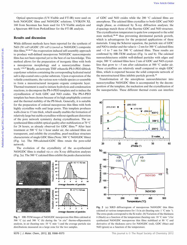
Fig. 1 HR-TEM images of NiO/GDCmesoporous thin films calcined at
500 �C (a) and 300 �C (b) during the ‘‘in situ’’ thermo-ellipsometric
analysis, in air (heating rate: 10 �C min�1) and the average particle size
distributions measured on a large zone for the two samples.
9370 | J. Mater. Chem., 2012, 22, 9368–9373
of GDC and NiO oxides while the 200 �C calcined films are
amorphous. The calcined films crystallize to both GDC and NiO
single phase, as evidenced by X-ray diffraction analyses; the
d-spacings match those of the fluorine GDC and NiO structure.
The crystallization temperature is quite low compared to the solid
state method,38–40 thus preventing detrimental particle growth,
which is advantageous for the projected applications of these
materials. Using the Scherrer equation, the particle size of GDC
andNiO is similar and the value is�2 nm for 300 �C calcined films
and �5 to 7 nm for 500 �C calcined films. These results are
confirmed by HR-TEM analyses (Fig. 1a and b). The calcined
nanoarchitectures exhibit well-defined particles with edges and
steps; 300 �C calcined films have 2 nm of GDC and NiO crystal-
lites that grow to �5 nm after calcination at 500 �C under air.
These crystallites are relatively small compared to single GDC
films, which is expected because the solid composite network of
the mesostructured films inhibits particle growth.41
Transformation of the amorphous nanoarchitecture into
nanocrystalline NiO/GDC films is accompanied by the decom-
position of the template, the nucleation and the crystallization of
the nanoparticles. These different thermal events can interfere
Fig. 2 (a) XRD diffractogram of mesoporous NiO/GDC thin films
calcined at various temperatures for 1 h in air (heating rate: 1 �C min�1).
The extra-peaks correspond to the Si-wafer. (b) Variation of the thickness
h (black) as a function of the temperature (heating rate: 10 �C min�1) for
synthesized NiO/GDC mesoporous thin films stabilized at 80 �C and
derivative of the thickness curve for NiO/GDC (red), GDC (blue) and
NiO (green) as a function of the temperature.
This journal is ª The Royal Society of Chemistry 2012
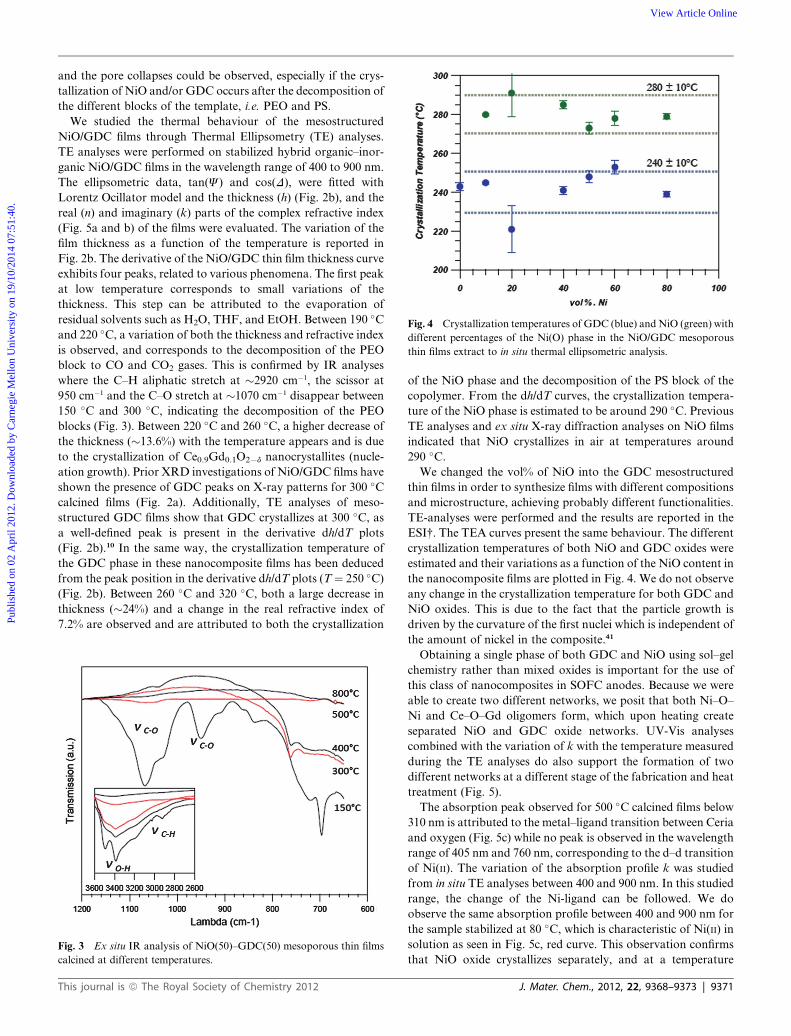
Fig. 4 Crystallization temperatures of GDC (blue) andNiO (green) with
different percentages of the Ni(O) phase in the NiO/GDC mesoporous
thin films extract to in situ thermal ellipsometric analysis.
Publ
ishe
d on
02
Apr
il 20
12. D
ownl
oade
d by
Car
negi
e M
ello
n U
nive
rsity
on
19/1
0/20
14 0
7:51
:40.
View Article Online
and the pore collapses could be observed, especially if the crys-
tallization of NiO and/or GDC occurs after the decomposition of
the different blocks of the template, i.e. PEO and PS.
We studied the thermal behaviour of the mesostructured
NiO/GDC films through Thermal Ellipsometry (TE) analyses.
TE analyses were performed on stabilized hybrid organic–inor-
ganic NiO/GDC films in the wavelength range of 400 to 900 nm.
The ellipsometric data, tan(J) and cos(D), were fitted with
Lorentz Ocillator model and the thickness (h) (Fig. 2b), and the
real (n) and imaginary (k) parts of the complex refractive index
(Fig. 5a and b) of the films were evaluated. The variation of the
film thickness as a function of the temperature is reported in
Fig. 2b. The derivative of the NiO/GDC thin film thickness curve
exhibits four peaks, related to various phenomena. The first peak
at low temperature corresponds to small variations of the
thickness. This step can be attributed to the evaporation of
residual solvents such as H2O, THF, and EtOH. Between 190 �Cand 220 �C, a variation of both the thickness and refractive index
is observed, and corresponds to the decomposition of the PEO
block to CO and CO2 gases. This is confirmed by IR analyses
where the C–H aliphatic stretch at �2920 cm�1, the scissor at
950 cm�1 and the C–O stretch at �1070 cm�1 disappear between
150 �C and 300 �C, indicating the decomposition of the PEO
blocks (Fig. 3). Between 220 �C and 260 �C, a higher decrease of
the thickness (�13.6%) with the temperature appears and is due
to the crystallization of Ce0.9Gd0.1O2�d nanocrystallites (nucle-
ation growth). Prior XRD investigations of NiO/GDC films have
shown the presence of GDC peaks on X-ray patterns for 300 �Ccalcined films (Fig. 2a). Additionally, TE analyses of meso-
structured GDC films show that GDC crystallizes at 300 �C, asa well-defined peak is present in the derivative dh/dT plots
(Fig. 2b).10 In the same way, the crystallization temperature of
the GDC phase in these nanocomposite films has been deduced
from the peak position in the derivative dh/dT plots (T¼ 250 �C)(Fig. 2b). Between 260 �C and 320 �C, both a large decrease in
thickness (�24%) and a change in the real refractive index of
7.2% are observed and are attributed to both the crystallization
Fig. 3 Ex situ IR analysis of NiO(50)–GDC(50) mesoporous thin films
calcined at different temperatures.
This journal is ª The Royal Society of Chemistry 2012
of the NiO phase and the decomposition of the PS block of the
copolymer. From the dh/dT curves, the crystallization tempera-
ture of the NiO phase is estimated to be around 290 �C. PreviousTE analyses and ex situ X-ray diffraction analyses on NiO films
indicated that NiO crystallizes in air at temperatures around
290 �C.We changed the vol% of NiO into the GDC mesostructured
thin films in order to synthesize films with different compositions
and microstructure, achieving probably different functionalities.
TE-analyses were performed and the results are reported in the
ESI†. The TEA curves present the same behaviour. The different
crystallization temperatures of both NiO and GDC oxides were
estimated and their variations as a function of the NiO content in
the nanocomposite films are plotted in Fig. 4. We do not observe
any change in the crystallization temperature for both GDC and
NiO oxides. This is due to the fact that the particle growth is
driven by the curvature of the first nuclei which is independent of
the amount of nickel in the composite.41
Obtaining a single phase of both GDC and NiO using sol–gel
chemistry rather than mixed oxides is important for the use of
this class of nanocomposites in SOFC anodes. Because we were
able to create two different networks, we posit that both Ni–O–
Ni and Ce–O–Gd oligomers form, which upon heating create
separated NiO and GDC oxide networks. UV-Vis analyses
combined with the variation of k with the temperature measured
during the TE analyses do also support the formation of two
different networks at a different stage of the fabrication and heat
treatment (Fig. 5).
The absorption peak observed for 500 �C calcined films below
310 nm is attributed to the metal–ligand transition between Ceria
and oxygen (Fig. 5c) while no peak is observed in the wavelength
range of 405 nm and 760 nm, corresponding to the d–d transition
of Ni(II). The variation of the absorption profile k was studied
from in situ TE analyses between 400 and 900 nm. In this studied
range, the change of the Ni-ligand can be followed. We do
observe the same absorption profile between 400 and 900 nm for
the sample stabilized at 80 �C, which is characteristic of Ni(II) in
solution as seen in Fig. 5c, red curve. This observation confirms
that NiO oxide crystallizes separately, and at a temperature
J. Mater. Chem., 2012, 22, 9368–9373 | 9371
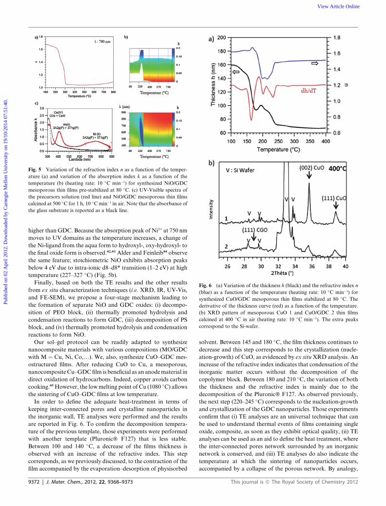
Fig. 6 (a) Variation of the thickness h (black) and the refractive index n
(blue) as a function of the temperature (heating rate: 10 �C min�1) for
synthesized CuO/GDC mesoporous thin films stabilized at 80 �C. Thederivative of the thickness curve (red) as a function of the temperature.
(b) XRD pattern of mesoporous CuO 1 and CuO/GDC 2 thin films
calcined at 400 �C in air (heating rate: 10 �C min�1). The extra peaks
correspond to the Si-wafer.
Fig. 5 Variation of the refraction index n as a function of the temper-
ature (a) and variation of the absorption index k as a function of the
temperature (b) (heating rate: 10 �C min�1) for synthesized NiO/GDC
mesoporous thin films pre-stabilized at 80 �C. (c) UV-Visible spectra of
the precursors solution (red line) and NiO/GDC mesoporous thin films
calcined at 500 �C for 1 h, 10 �Cmin�1 in air. Note that the absorbance of
the glass substrate is reported as a black line.
Publ
ishe
d on
02
Apr
il 20
12. D
ownl
oade
d by
Car
negi
e M
ello
n U
nive
rsity
on
19/1
0/20
14 0
7:51
:40.
View Article Online
higher thanGDC. Because the absorption peak of Ni2+ at 750 nm
moves to UV domains as the temperature increases, a change of
the Ni-ligand from the aqua form to hydroxyl-, oxy-hydroxyl- to
the final oxide form is observed.42,43 Alder and Feinleib44 observe
the same feature; stoichiometric NiO exhibits absorption peaks
below 4 eV due to intra-ionic d8–d8* transition (1–2 eV) at high
temperature (227–327 �C) (Fig. 5b).Finally, based on both the TE results and the other results
from ex situ characterization techniques (i.e. XRD, IR, UV-Vis,
and FE-SEM), we propose a four-stage mechanism leading to
the formation of separate NiO and GDC oxides: (i) decompo-
sition of PEO block, (ii) thermally promoted hydrolysis and
condensation reactions to form GDC, (iii) decomposition of PS
block, and (iv) thermally promoted hydrolysis and condensation
reactions to form NiO.
Our sol–gel protocol can be readily adapted to synthesize
nanocomposite materials with various compositions (MO/GDC
with M ¼ Cu, Ni, Co,.). We, also, synthesize CuO–GDC mes-
ostructured films. After reducing CuO to Cu, a mesoporous,
nanocomposite Cu–GDCfilm is beneficial as an anodematerial in
direct oxidation of hydrocarbons. Indeed, copper avoids carbon
cooking.45However, the lowmelting point of Cu (1080 �C) allowsthe sintering of CuO–GDC films at low temperature.
In order to define the adequate heat-treatment in terms of
keeping inter-connected pores and crystalline nanoparticles in
the inorganic wall, TE analyses were performed and the results
are reported in Fig. 6. To confirm the decomposition tempera-
ture of the previous template, those experiments were performed
with another template (Pluronic� F127) that is less stable.
Between 100 and 140 �C, a decrease of the films thickness is
observed with an increase of the refractive index. This step
corresponds, as we previously discussed, to the contraction of the
film accompanied by the evaporation–desorption of physisorbed
9372 | J. Mater. Chem., 2012, 22, 9368–9373
solvent. Between 145 and 180 �C, the film thickness continues to
decrease and this step corresponds to the crystallization (nucle-
ation-growth) of CuO, as evidenced by ex situ XRD analysis. An
increase of the refractive index indicates that condensation of the
inorganic matter occurs without the decomposition of the
copolymer block. Between 180 and 210 �C, the variation of both
the thickness and the refractive index is mainly due to the
decomposition of the Pluronic� F127. As observed previously,
the next step (220–245 �C) corresponds to the nucleation-growth
and crystallization of the GDC nanoparticles. Those experiments
confirm that (i) TE analyses are an universal technique that can
be used to understand thermal events of films containing single
oxide, composite, as soon as they exhibit optical quality, (ii) TE
analyses can be used as an aid to define the heat treatment, where
the inter-connected pores network surrounded by an inorganic
network is conserved, and (iii) TE analyses do also indicate the
temperature at which the sintering of nanoparticles occurs,
accompanied by a collapse of the porous network. By analogy,
This journal is ª The Royal Society of Chemistry 2012

Publ
ishe
d on
02
Apr
il 20
12. D
ownl
oade
d by
Car
negi
e M
ello
n U
nive
rsity
on
19/1
0/20
14 0
7:51
:40.
View Article Online
we expect that a similar nanocomposite structure composed of
a complex oxide such as La0.6Sr0.4Co0.2Fe0.8O3 and GDC
nanoparticles will contain optimized three-phase boundary
catalytic sites for use as micro-SOFC cathodes.
We also prepared mesostructured Ni/GDC films, by heating
the NiO/GDC mesoporous films at 550 �C under 10% H2/N2.
During this step, NiO is reduced to Ni, as it is evidenced by ex
situ XRD analyses (S.I.). We, then, measured the polarization
resistance of the films at 500 �C and found that the film exhibits
mixed conductivity as the film resistance is much lower than the
one observed for GDC mesostructured films at the same
temperature (13.9 U cm2 for GDC and 0.71 U cm2 at 500 �C for
Ni(50)/GDC(50)). This indicates that NiO is reduced to Ni and
the Ni network is percolated.
Conclusions
In summary, we describe a low-temperature, facile route to
synthesize GDC-based nanocomposites as mesoporous thin films
for micro-SOFC anodes. The thermal behaviour of these
mesoporous GDC-based nanocomposites was studied from
TE-analyses in order to characterize the decomposition of the
template, the crystallization and the sintering of these films. This
technique combined with other characterization techniques
(XRD, FE-SEM, IR,.) allows optimization of thermal
processes that permit conservation of interconnected porous
networks and crystalline inorganic pore walls. Such a micro-
structure is suitable for the development of efficient SOFC
compounds because it yields mixed conductivity. In conclusion,
we demonstrate that the sol–gel method containing a surfactant
and combined with the dip-coating approach is readily adapted
to multi-component GDC-based nanocomposites containing
simple (NiO and CuO) or more complex oxides (La0.6Sr0.4-
Co0.2Fe0.8O3) of relevance to electrocatalytic reactions.
Acknowledgements
The authors thank the EADS Foundation for supporting
G. M€uller PhD grant. They also thank D. Montero for doing
FE-SEM analyses.
Notes and references
1 C. Sanchez, C. Boissiere, D. Grosso, C. Laberty and L. Nicole, Chem.Mater., 2008, 20, 682–737.
2 B.-L. Su, C. Sanchez and X.-Y. Yang, Insights into hierarchicallystructured porous materials : from nanoscience to catalysis,separation, optics, energy and life science, Wiley-VCH Verlag & Co.KGaA, Boschstr, Weinheim, Germany, 2012, vol. 12, p. 69469.
3 C. Sanchez and B. Lebeau, MRS Bull., 2001, 26, 377–387.4 S. I. Najafi, T. Touam, R. Sara, M. P. Andrews and M. A. Fardad,J. Lightwave Technol., 1998, 16, 1640–1646.
5 G. A. Seisenbaeva, M. P. Moloney, R. Tekoriute, A. Hardy-Dessources, J. M. Nedelec, Y. K. Gun’ko and V. G. Kessler,Langmuir, 2010, 26, 9809–9817.
6 V. V. Guliants, M. A. Carreon and Y. S. Lin, J. Membr. Sci., 2004,235, 53–72.
7 H. Choi, E. Stathatos and D. D. Dionysiou, Appl. Catal., B, 2006, 63,60–67.
8 T. Brezesinski, A. Fischer, K. Iimura, C. Sanchez, D. Grosso,M. Antonietti and B. M. Smarsly, Adv. Funct. Mater., 2006, 16,1433–1440.
9 A. Kay and M. Gratzel, Chem. Mater., 2002, 14, 2930–2935.
This journal is ª The Royal Society of Chemistry 2012
10 J. Hierso, O. Sel, A. Ringuede, C. Laberty-Robert, L. Bianchi,D. Grosso and C. Sanchez, Chem. Mater., 2009, 21, 2184–2192.
11 A. Atkinson, S. Barnett, R. J. Gorte, J. T. S. Irvine, A. J. McEvoy,M. Mogensen, S. C. Singhal and J. Vohs, Nat. Mater., 2004, 3, 17–27.
12 K. C. Wincewicz and J. S. Cooper, J. Power Sources, 2005, 140, 280–296.
13 S. Hilaire, X. Wang, T. Luo, R. J. Gorte and J. Wagner, Appl. Catal.,A, 2001, 215, 271–278.
14 Q. Fu, A. Weber andM. Flytzani-Stephanopoulos,Catal. Lett., 2001,77, 87–95.
15 Q. Fu, H. Saltsburg and M. Flytzani-Stephanopoulos, Science, 2003,301, 935–938.
16 D. Andreeva, V. Idakiev, T. Tabakova, L. Ilieva, P. Falaras,A. Bourlinos and A. Travlos, Catal. Today, 2002, 72, 51–57.
17 D. Beckel, A. Bieberle-Hutter, A. Harvey, A. Infortuna,U. P. Muecke, M. Prestat, J. L. M. Rupp and L. J. Gauckler,J. Power Sources, 2007, 173, 325–345.
18 H. L. Tuller, Solid State Ionics, 2000, 131, 143–157.19 H. L. Tuller and A. S. Nowick, J. Electrochem. Soc., 1975, 122, 255–
259.20 J. L. M. Rupp, C. Solenthaler, P. Gasser, U. P. Muecke and
L. J. Gauckler, Acta Mater., 2007, 55, 3505–3512.21 J. L. M. Rupp, A. Infortuna and L. J. Gauckler, Acta Mater., 2006,
54, 1721–1730.22 J. L. M. Rupp, A. Infortuna and L. J. Gauckler, J. Am. Ceram. Soc.,
2007, 90, 1792–1797.23 J. L. M. Rupp and L. J. Gauckler, Solid State Ionics, 2006, 177, 2513–
2518.24 A. Infortuna, A. S. Harvey, U. P. Muecke and L. J. Gauckler, Phys.
Chem. Chem. Phys., 2009, 11, 3663–3670.25 U. P. Muecke, K. Akiba, A. Infortuna, T. Salkus, N. V. Stus and
L. J. Gauckler, Solid State Ionics, 2008, 178, 1762–1768.26 U. P. Muecke, S. Graf, U. Rhyner and L. J. Gauckler, Acta Mater.,
2008, 56, 677–687.27 S. Pinol, M. Morales and F. Espiell, in 2nd National Congress on Fuel
Cells, Elsevier Science Bv, Madrid, Spain, 2006, pp. 2–8.28 T. Suzuki, I. Kosacki and H. U. Anderson, Solid State Ionics, 2002,
151, 111–121.29 N. Oishi, A. Atkinson, N. P. Brandon, J. A. Kilner and
B. C. H. Steele, J. Am. Ceram. Soc., 2005, 88, 1394–1396.30 I. M. Hung, K. Z. Fung, D. T. Hung and M. H. Hon, J. Eur. Ceram.
Soc., 2008, 28, 1161–1167.31 D. M. Lyons, K. M. Ryan and M. A. Morris, J. Mater. Chem., 2002,
12, 1207–1212.32 J. D. Bass, D. Grosso, C. Boissiere and C. Sanchez, J. Am. Chem.
Soc., 2008, 130, 7882–7897.33 B. Louis, N. Krins, M. Faustini and D. Grosso, J. Phys. Chem. C,
2011, 115, 3115–3122.34 P. Debye and P. Scherrer, Phys. Z., 1917, 18, 291–301.35 G. Laukaitis and J. Dudonis, J. Alloys Compd., 2008, 459, 320–
327.36 G. J. D. Soler-illia, C. Sanchez, B. Lebeau and J. Patarin, Chem. Rev.,
2002, 102, 4093–4138.37 D. Grosso, F. Cagnol, G. Soler-Illia, E. L. Crepaldi, H. Amenitsch,
A. Brunet-Bruneau, A. Bourgeois and C. Sanchez, Adv. Funct.Mater., 2004, 14, 309–322.
38 H. Mitsuyasu, Y. Nonaka and K. Eguchi, Solid State Ionics, 1998,113, 279–284.
39 K. Eguchi, N. Akasaka, H. Mitsuyasu and Y. Nonaka, Solid StateIonics, 2000, 135, 589–594.
40 Y. J. Leng, S. H. Chan, S. P. Jiang and K. A. Khor, Solid State Ionics,2004, 170, 9–15.
41 G. Baldinozzi, G. Muller, C. Laberty-Robert, D. Gosset,D. Simeone and C. Sanchez, J. Phys. Chem. C, 2012, DOI:10.1021/jp211872z.
42 Y. Zhou, Y. Y. Geng, D. H. Gu, W. B. Gu and Z. Jiang, Phys. B,2010, 405, 3875–3878.
43 M. Chigane,M. Ishikawa andH. Inoue, Sol. EnergyMater. Sol. Cells,2000, 64, 65–72.
44 D. Adler and J. Feinleib, Phys. Rev. B: Solid State, 1970, 2, 3112–3134.
45 H. L. Maynard and J. P. Meyers, J. Vac. Sci. Technol., B, 2002, 20,1287–1297.
J. Mater. Chem., 2012, 22, 9368–9373 | 9373


![Crystallization-Induced Energy Level Change of [6,6]-Phenyl ...opac.ll.chiba-u.jp/da/curator/100085/Crystallization...1 Crystallization-Induced Energy Level Change of [6,6]-Phenyl-C61-Butyric](https://static.fdocument.pub/doc/165x107/60dcd50502116a77a0410407/crystallization-induced-energy-level-change-of-66-phenyl-opacllchiba-ujpdacurator100085crystallization.jpg)