
UML2 UML2 - WIDE Project · completion transition Activity View (Activity Diagram) • An activity...
25
Koichiro Ochimizu, JAIST UML2.0 1 Schedule(2/2) • Feb. 25th – 13:00 Outline of UML: Static Modeling (details of class definition) – 14:30 Outline of UML: Dynamic Modeling (state machine, communication diagram, sequence diagram) • March. 4th – 13:00 Unified Process and Usecase-Driven Approach Case Study: Elevator Control System – 14:30 UML2.0, Contribution of OO in SE UML2(UML2.0) James Rumbaugh, Ivar Jacobson, Grady Booch, “The Unified Modeling Language Reference Manual, Second Edition”, Addison-Wesley, 2005. Koichiro Ochimizu Japan Advanced Institute of Science and technologies School of Information Science
Transcript of UML2 UML2 - WIDE Project · completion transition Activity View (Activity Diagram) • An activity...
Koichiro Ochimizu, JAIST
UML2.0 1
Schedule(2/2)• Feb. 25th
– 13:00 Outline of UML: Static Modeling(details of class definition)
– 14:30 Outline of UML: Dynamic Modeling(state machine, communication diagram, sequence diagram)
• March. 4th– 13:00 Unified Process and Usecase-Driven Approach
Case Study: Elevator Control System– 14:30 UML2.0, Contribution of OO in SE
UML2(UML2.0)
James Rumbaugh, Ivar Jacobson, Grady Booch, “The Unified Modeling Language Reference Manual, Second Edition”,
Addison-Wesley, 2005.
Koichiro OchimizuJapan Advanced Institute of
Science and technologiesSchool of Information Science
Koichiro Ochimizu, JAIST
UML2.0 2
MDA and CBSD
• MDA ( Model Driven Architecture)• CBSD (Component Based Software
Development)
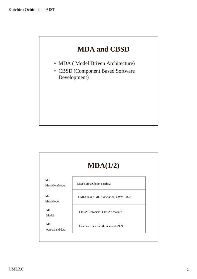
MDA(1/2)
M3
MetaMetaModel
M2
MetaModel
M1
Model
M0
objects and data
MOF (Meta Object Facility)
UML Class, UML Association, CWM Table
Class “Customer”, Class “Account”
Customer Jane Smith, Account 2989

Koichiro Ochimizu, JAIST
UML2.0 3
MDA(2/2)
Meta Language
Language 1 Language 2MappingDefinition
PIM(Platform
IndependentModel)
PIM(PlatformSpecificModel)
Translator
is-described-by
is-described-by is-described-by
is-described-by
is-used-by
New Features of UML2.0
• Sequence Diagram constructs and notation based largely on the ITU(International Telecommunication Union)Message Sequence Chart standard, adapted to make it more object-oriented
• Decoupling of activity modeling concepts from state machines and use of notation popular in the business modeling community.
• Contextual modeling constructs for the internal composition of classes and collaborations. Theses constructs permit both loose and strict encapsulation and wiring of internal structures from smaller parts.
• Repositioning of components as design constructs and artifacts as physical entities that are deployed
Koichiro Ochimizu, JAIST
UML2.0 4
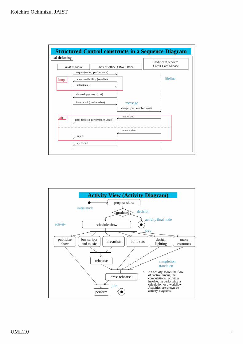
Structured Control constructs in a Sequence Diagram sd ticketing
box of office:Box Officekiosk:KioskCredit card service: Credit Card Service
request(count, performance)
show availability (seat-list)
select(seat)
loop
demand payment (cost)
insert card (card number)
charge (card number, cost)
eject card
authorized
reject
unauthorized
print tickets ( performance ,seats )alt
lifeline
message
propose show
produce?
schedule show
publicizeshow
buy scriptsand music hire artists build sets design
lightingmake
costumes
rehearse
dress rehearsal
perform
initial nodedecision
activity final nodeactivity
fork
join
completion transition
Activity View (Activity Diagram)
• An activity shows the flow of control among the computational activities involved in performing a calculation or a workflow. Activities are shown on activity diagrams
Koichiro Ochimizu, JAIST
UML2.0 5
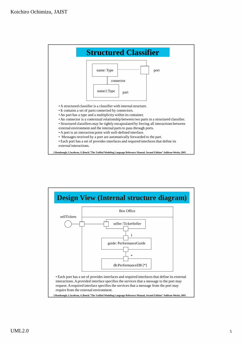
Structured Classifier
J.Rumbaugh, I.Jacobson, G.Booch,”The Unified Modeling Language Reference Manual, Second Edition” Addison-Wesley 2005
name: Type
name1:Type
port
connector
part
• A structured classifier is a classifier with internal structure.• It contains a set of parts connected by connectors.• An part has a type and a multiplicity within its container.• An connector is a contextual relationship between two parts in a structured classifier.• Structured classifiers may be tightly encapsulated by forcing all interactions between external environment and the internal parts to pass through ports.• A port is an interaction point with well-defined interface.• Messages received by a port are automatically forwarded to the part.• Each port has a set of provides interfaces and required interfaces that define its external interactions.
Design View (Internal structure diagram)Box Office
seller: TicketSeller
guide: PerformanceGuide
db:PerformanceDB [*]
sellTickets
1
*
J.Rumbaugh, I.Jacobson, G.Booch,”The Unified Modeling Language Reference Manual, Second Edition” Addison-Wesley 2005
• Each port has a set of provides interfaces and required interfaces that define its external interactions. A provided interface specifies the services that a message to the port may request. A required interface specifies the services that a message from the port may require from the external environment.
Koichiro Ochimizu, JAIST
UML2.0 6
Design View (component diagram)
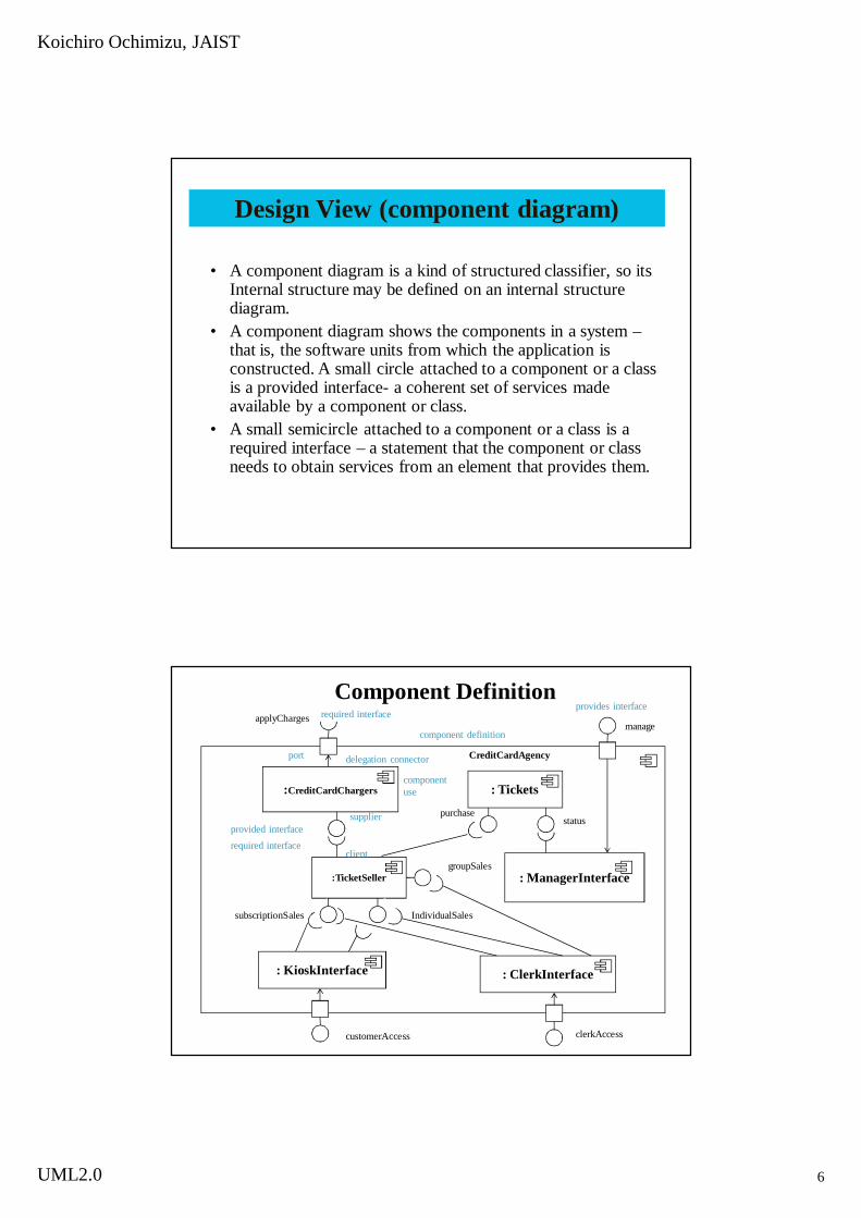
• A component diagram is a kind of structured classifier, so its Internal structure may be defined on an internal structure diagram.
• A component diagram shows the components in a system –that is, the software units from which the application is constructed. A small circle attached to a component or a class is a provided interface- a coherent set of services made available by a component or class.
• A small semicircle attached to a component or a class is a required interface – a statement that the component or class needs to obtain services from an element that provides them.
Component Definition
:CreditCardChargers : Tickets
:TicketSeller
: KioskInterface : ClerkInterface
: ManagerInterface
subscriptionSales IndividualSales
groupSales
required interface
purchasestatus
applyChargesmanage
provides interface
component definition
port delegation connector
component use
provided interfacerequired interface
supplier
client
CreditCardAgency
customerAccess clerkAccess

Koichiro Ochimizu, JAIST
UML2.0 7
Component Diagram(is a kind of structured classifier)
CreditCardChargesTickets
KioskInterface ClerkInterface
ManagerInterface
subscriptionSales individualSales
required interface
purchase
status
applyCharges
manage
provided interface on port
component definition
port
provided interface
customerAccess clerkAccess
groupSales
individualSalessubscriptionSales
TicketSellergroupSales
subscriptionSales IndividualSales
purchasecharge
chargestatus
CreditCardAgencyapplyCharges
manage customerAccess clerkAcsess
compatible interface
Views of UML1.5
Use-CaseView
ConcurrencyView
LogicalView
DeploymentView
ComponentView
H.E. Eriksson and M. Penker, “UML Toolkit” John Wiley & Sons, Inc.
Koichiro Ochimizu, JAIST
UML2.0 8
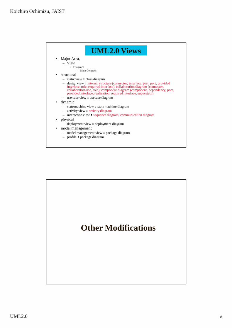
UML2.0 Views• Major Area,
– View• Diagram
– Main Concepts• structural
– static view:class diagram– design view:internal structure (connector, interface, part, port, provided
interface, role, required interface), collaboration diagram (connector, collaboration use, role), component diagram (component, dependency, port, provided interface, realization, required interface, subsystem)
– use case view:usecase diagram• dynamic
– state machine view:state machine diagram– activity view:activity diagram– interaction view:sequence diagram, communication diagram
• physical– deployment view:deployment diagram
• model management– model management view:package diagram– profile:package diagram
Other Modifications
Koichiro Ochimizu, JAIST
UML2.0 9
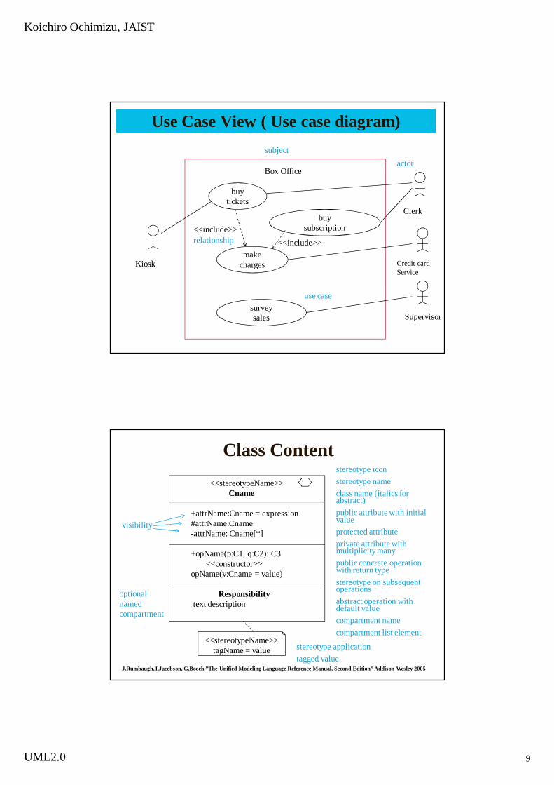
Use Case View ( Use case diagram)
buytickets
buysubscription
makecharges
surveysales
Box Office
<<include>><<include>>relationship
use case
actorsubject
Clerk
Credit card Service
Supervisor
Kiosk
Class Content<<stereotypeName>>
Cname
+attrName:Cname = expression#attrName:Cname-attrName: Cname[*]
+opName(p:C1, q:C2): C3<<constructor>>
opName(v:Cname = value)
Responsibilitytext description
J.Rumbaugh, I.Jacobson, G.Booch,”The Unified Modeling Language Reference Manual, Second Edition” Addison-Wesley 2005
visibility
optional named compartment
stereotype iconstereotype nameclass name (italics for abstract)public attribute with initial valueprotected attributeprivate attribute with multiplicity manypublic concrete operation with return typestereotype on subsequent operationsabstract operation with default valuecompartment namecompartment list element
<<stereotypeName>>tagName = value stereotype application
tagged value
Koichiro Ochimizu, JAIST
UML2.0 10
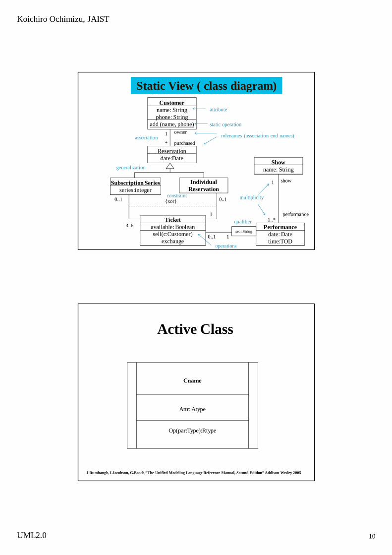
Static View ( class diagram)Customer
name: Stringphone: String
add (name, phone)
Reservationdate:Date
Subscription Seriesseries:integer
IndividualReservation
Ticketavailable: Booleansell(c:Customer)
exchange
Showname: String
Performancedate: Datetime:TOD
seat:String
1
*
0..1 0..1
3..6
1
10..1
1
1..*
{xor}
show
performance
owner
purchased
attribute
static operation
rolenames (association end names)association
generalization
constraint multiplicity
qualifier
operations
Active Class
Cname
Attr: Atype
Op(par:Type):Rtype
J.Rumbaugh, I.Jacobson, G.Booch,”The Unified Modeling Language Reference Manual, Second Edition” Addison-Wesley 2005

Koichiro Ochimizu, JAIST
UML2.0 11
Relationship
J.Rumbaugh, I.Jacobson, G.Booch,”The Unified Modeling Language Reference Manual, Second Edition” Addison-Wesley 2005
<<kind>>
association
generalization
realization
dependency
Aname
Design View (collaboration diagram)• A collaboration is a contextual relationship among
a set of objects that work together to fullfill some purpose.
• It contains a collection of roles ‒ contextual slots within a generic pattern that can be played by, or bound to, individual objects.
TheatreSales
kiosk: Kiosk[*] :BoxOffice terminal: SalesTerminal[*]1 *
*
1

Koichiro Ochimizu, JAIST
UML2.0 12
Interaction View
• The interaction view describes sequence of message exchanges among the parts of a system.
• An interaction is based on a structured classifier or a collaboration.
• A role is a slot that may be filled by objects in a particular us of an interaction.
• Interaction view shows the flow of control across many objects and is displayed in two diagrams focused on different aspects: sequence diagrams and communication diagrams. The communication diagram is called a collaboration diagram in UML1.5.
Interaction View ( Sequence Diagram )sd ticketing
box of office:Box Officekiosk:KioskCredit card service: Credit Card Service
request(count, performance)
show availability (seat-list)
select(seat)
loop
demand payment (cost)
insert card (card number)
charge (card number, cost)
eject card
authorized
reject
unauthorized
print tickets ( performance ,seats )alt
lifeline
message

Koichiro Ochimizu, JAIST
UML2.0 13
Interaction View ( communication diagram)
kiosk
ticketSeller
performanceGuide
role bound to active objects
link
connector bound to persistent links
message
connector bound to transitive links
guide: DBCluster
db db: PerformanceDB[*]3: seat-list:=lock(count)
6: claim(seats)
7:unlock(seat-list)
1: request(count, performance)4: offer(seat-list)5: buy(seats)8: comfirm(seats, cost)
2: db := findDB( performance)guide
State Machine View (state machine diagram)
Available Locked Sold
subscribe/assign()
exchange(other)/assign();reset(other)
timed out/unlock()
select/lock()
reject/unlock()
accept/buy()stateinitial state
trigger event event parameter effect
transition
Koichiro Ochimizu, JAIST
UML2.0 14
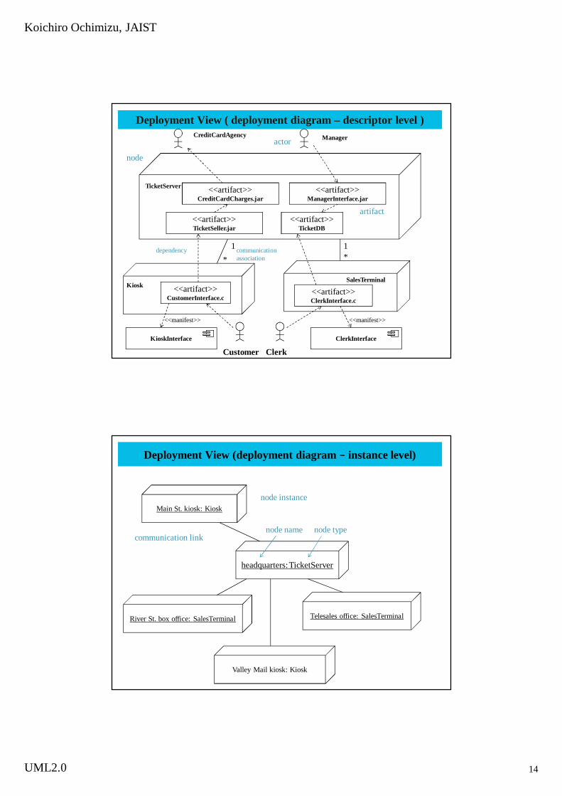
Deployment View ( deployment diagram – descriptor level )
<<artifact>>CustomerInterface.c
KioskInterface ClerkInterface
Customer Clerk
Kiosk<<artifact>>ClerkInterface.c
SalesTerminal
CreditCardAgency Manager
TicketServer <<artifact>>CreditCardCharges.jar
<<artifact>>ManagerInterface.jar
<<artifact>>TicketSeller.jar
<<artifact>>TicketDB
1 1* *
artifact
actor
node
dependency communication association
<<manifest>><<manifest>>
Deployment View (deployment diagram ‒ instance level)
Main St. kiosk: Kiosk
headquarters: TicketServer
River St. box office: SalesTerminal Telesales office: SalesTerminal
Valley Mail kiosk: Kiosk
node instance
node name node typecommunication link

Koichiro Ochimizu, JAIST
UML2.0 15
Model Management View ( package diagram)
Operations
Purchasing
Planning
Publicity
Box Office
Ticket Sales
Scheduling
CustomerRecords
TicketRecords
Accounting Payroll
dependency
package
package
Model Management View ( Profile)
• The profile mechanism permits limited changes to UML without modifying the underlying metamodel.
• UML includes three main extensibility constructs: constraints, stereotypes, and tagged
Showname: String
<<database>>TicketDB
<<database>>Scheduling
{names for one season must be unique}
TicketDB
<<authorship>>author = “Frank Martin”
Due = Dec.31,2009
constraint
stereotype
application
stereotype icon
tagged values

Koichiro Ochimizu, JAIST
UML2.0 16
Schedule(2/2)• Feb. 25th
– 13:00 Outline of UML: Static Modeling(details of class definition)
– 14:30 Outline of UML: Dynamic Modeling(state machine, communication diagram, sequence diagram)
• March. 4th– 13:00 Unified Process and Usecase-Driven Approach
Case Study: Elevator Control System– 14:30 UML2.0, Contribution of OO in SE
OOT in SE
Koichiro OchimizuJapan Advanced Institute of
Science and TechnologiesSchool of Information Science
Koichiro Ochimizu, JAIST
UML2.0 17
What is Software Engineering?
Software Development is Challenging but Difficult to Achieve!
• Software entities are more complex than most things people build like buildings, automobiles or VLSI.
• Within only 30 years the amount of software in cars went from 0 to more than 10,000,000 lines of code. More than 2000 individual functions are realized or controlled by software in premium cars, today. 50-70% of the development costs of the software/hardware systems are software costs. (Manfred Broy, “Challenges in Automotive Software Engineering”, ICSE2006, pp33-42,2006)
Koichiro Ochimizu, JAIST
UML2.0 18
Why is Software Development so difficult ? (F.Brooks,Jr)
1. Complexity• Computer programs are complex by their nature:
a huge amount of parts and their relationships.2. Conformity
• Software can not be created in isolation, but must conform to real-world constraints – pre-existing hardware , third party components, government regulations, legacy data formats, and so on.
3. Changeability• Software is always evolving, as the outer
environments of software change. 4. Invisibility
– Software doesn’t exist in a way that can be represented using geometric models, especially for representing the behavior of software.
Why is Software Development so difficult ? (F.Brooks,Jr)

Koichiro Ochimizu, JAIST
UML2.0 19
Who makes such a complex software? ?
• Human beings• A group of human being should collaborate to
complete the work within specified time and cost with producing high quality product.
• Difficult to deal with the following problems caused by human beings– Variation– Uncertainty– Contingency
Software Engineering can support their activities
• Software Engineering Technologies– Provide us to control the problems specific to
software developments– Support the team to proceed the work smoothly
Koichiro Ochimizu, JAIST
UML2.0 20
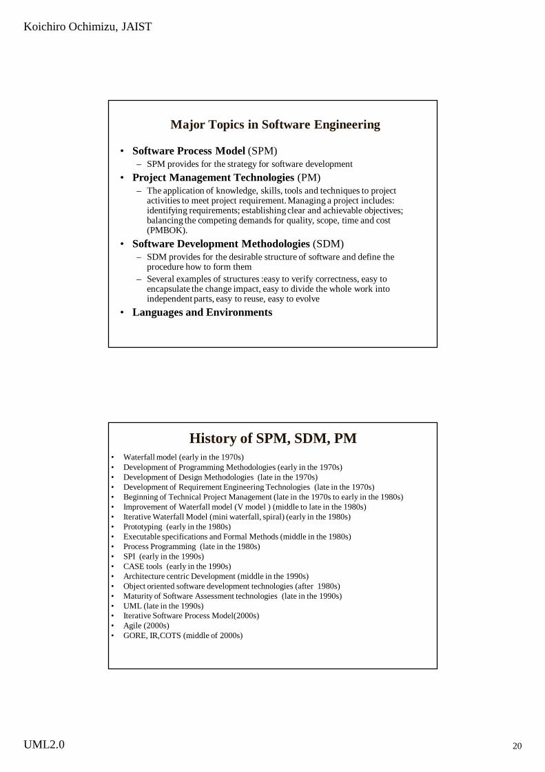
Major Topics in Software Engineering
• Software Process Model (SPM)– SPM provides for the strategy for software development
• Project Management Technologies (PM)– The application of knowledge, skills, tools and techniques to project
activities to meet project requirement. Managing a project includes: identifying requirements; establishing clear and achievable objectives; balancing the competing demands for quality, scope, time and cost (PMBOK).
• Software Development Methodologies (SDM)– SDM provides for the desirable structure of software and define the
procedure how to form them – Several examples of structures :easy to verify correctness, easy to
encapsulate the change impact, easy to divide the whole work into independent parts, easy to reuse, easy to evolve
• Languages and Environments
History of SPM, SDM, PM• Waterfall model (early in the 1970s)• Development of Programming Methodologies (early in the 1970s)• Development of Design Methodologies (late in the 1970s)• Development of Requirement Engineering Technologies (late in the 1970s)• Beginning of Technical Project Management (late in the 1970s to early in the 1980s)• Improvement of Waterfall model (V model ) (middle to late in the 1980s)• Iterative Waterfall Model (mini waterfall, spiral) (early in the 1980s)• Prototyping (early in the 1980s)• Executable specifications and Formal Methods (middle in the 1980s)• Process Programming (late in the 1980s)• SPI (early in the 1990s)• CASE tools (early in the 1990s)• Architecture centric Development (middle in the 1990s)• Object oriented software development technologies (after 1980s)• Maturity of Software Assessment technologies (late in the 1990s)• UML (late in the 1990s)• Iterative Software Process Model(2000s)• Agile (2000s)• GORE, IR,COTS (middle of 2000s)
Koichiro Ochimizu, JAIST
UML2.0 21
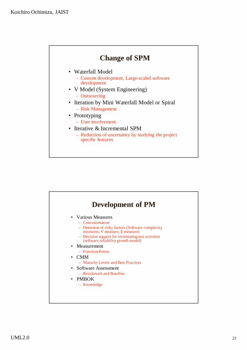
Change of SPM
• Waterfall Model– Custom development, Large-scaled software
development• V Model (System Engineering)
– Outsourcing• Iteration by Mini Waterfall Model or Spiral
– Risk Management• Prototyping
– User involvement• Iterative & Incremental SPM
– Reduction of uncertainty by studying the project specific features
Development of PM• Various Measures
– Cost-estimation– Detection of risky factors (Software complexity
measures, V measure, E measure)– Decision support for terminating test activities
(software reliability growth model)• Measurement
– Function Points• CMM
– Maturity Levels and Best Practices• Software Assessment
– Benchmark and Baseline• PMBOK
– Knowledge

Koichiro Ochimizu, JAIST
UML2.0 22
History of SDMWhat structures and How
• Structured Programming– easy to verify correctness a program, easy to divide the whole work into
independent parts• Information Hiding Module
– Encapsulation of change impact• Structured Analysis and Design
– Encapsulation of change impact• Requirement Engineering
– Requirements definition• Executable Specifications and Formal Methods
– Verifying and proving some properties of a program, Generation of a program, • Object-Orientation
– easy to encapsulate the change impact, easy to reuse and easy to evolve a program• Goal Oriented Requirement Engineering, Integrated Requirement Engineering,
COTS – Shortening the development time
Principles on Software Engineering1. Rigor and Formality
Rigorous approach enables us to produce more reliable products, control their cost, and increase our confidence in their reliability. Formality is a stronger requirement than rigor; it requires the software process to be driven and evaluated by mathematical laws.
2. Separation of ConcernsTo deal with different individual aspects of a problem and we can concentrate on each separately.
3. ModularityKind of Separation of Concerns. A complex system may be divided into simpler pieces called modules, allowing details of each module being handled in isolation.
4. AbstractionKind of Separation of Concerns; Separation of what from how. The we can identify the important aspects of a phenomenon and ignore its details.
5. Anticipation of ChangeWhen likely changes are identified, special care must be taken to proceed in a way that will make future changes easy to apply.
6. GeneralityGeneralizing the problem to make the solution more potential one for being reused.
7. IncrementalityA process that proceeds in stepwise fashion, in increments, for risk reduction.
Koichiro Ochimizu, JAIST
UML2.0 23
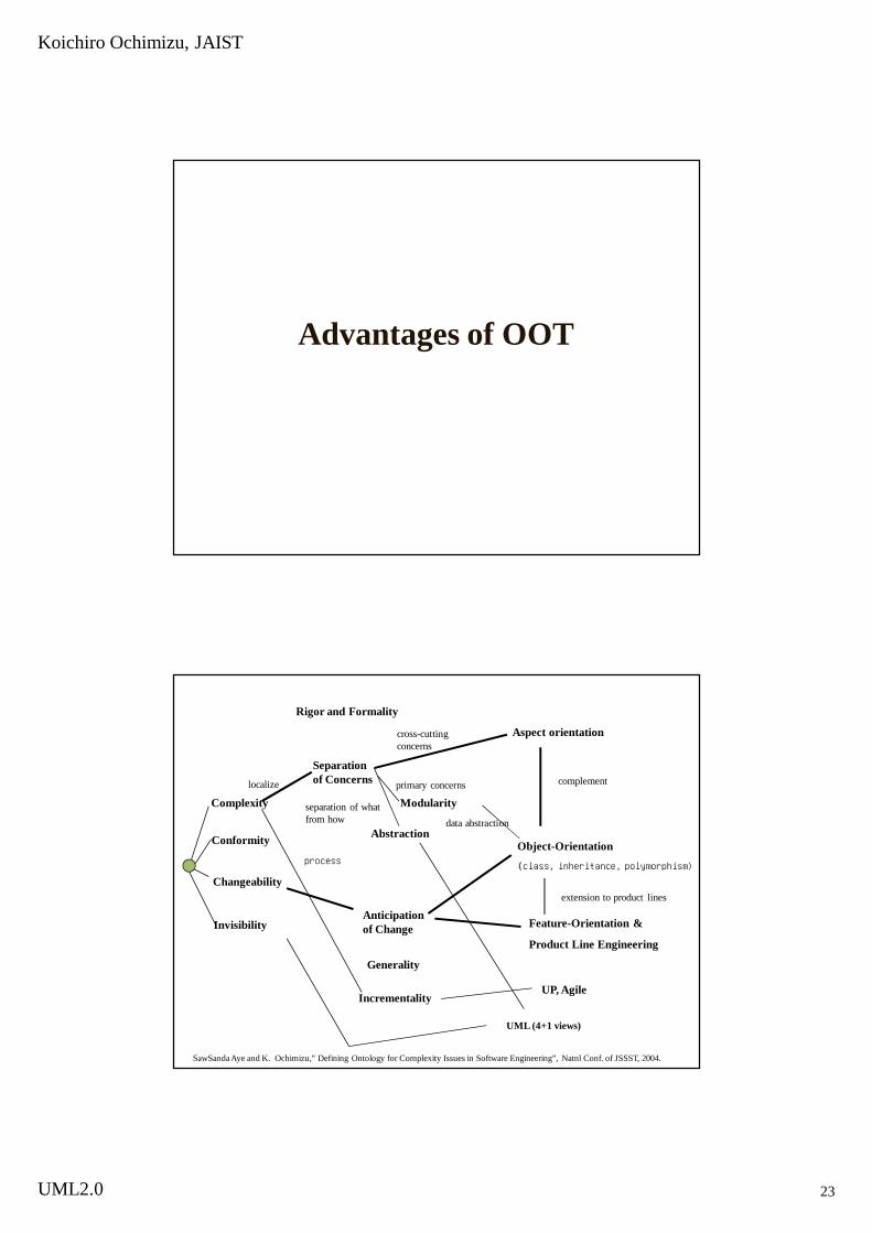
Advantages of OOT
Feature-Orientation &
Product Line Engineering
Object-Orientation
(class, inheritance, polymorphism)
complement
extension to product lines
cross-cutting concerns
localize
UML (4+1 views)
separation of what from how
primary concerns
data abstraction
Rigor and Formality
Separation of Concerns
Modularity
Abstraction
Anticipation of Change
Generality
Incrementality
Aspect orientation
Complexity
Conformity
Changeability
Invisibility
process
UP, Agile
SawSanda Aye and K. Ochimizu,” Defining Ontology for Complexity Issues in Software Engineering”, Natnl Conf. of JSSST, 2004.

Koichiro Ochimizu, JAIST
UML2.0 24
Object-Oriented Technology
• Mainly deal with Anticipation of Change
– Class for change of data structure– Inheritance for variation of properties over
the several problem domains– Polymorphism for common signature of
operations with different implementations
Aspect Oriented Programming
• Aspect oriented programming complement the defects of object oriented programming. We can not encapsulate all of the functionality in objects (primary concerns). For an example, Codes related to logging spread over related objects (cross cutting concerns). Aspect can define a cross cutting concerns separately.

Koichiro Ochimizu, JAIST
UML2.0 25
Feature Modeling and Product Line Engineering
• New technology for Anticipation of Change
– Common features and Product Specific features are arranged by Variation Point Analysis Techniques