UML Based Requirement Management Process in Mobile
42
UML Based Requirement Management Process in Mobile Multimedia Software Projects Jarno Kallio Master's Thesis Degree Programme in Welfare Technology
Transcript of UML Based Requirement Management Process in Mobile

UML Based Requirement Management Process
in Mobile Multimedia Software Projects
Jarno Kallio
Master's Thesis
Degree Programme in Welfare Technology

SAVONIA-AMMATTIKORKEAKOULUKoulutusohjelma, suuntautumisvaihtoehto (jos on)Hyvinvointiteknologia
TekijäJarno Kallio
Työn nimiUML Based Requirement Management Process in Mobile Multimedia Software Projects
Työn lajiOpinnäytetyö
Päiväys18.10.2010
Sivumäärä42
Työn ohjaajaYliopettaja Ari Suopelto
ToimeksiantajaPacketVideo Finland Oy
TiivistelmäVaatimushallinta on tärkeä aliprosessi ohjelmistojen kehityksessä. Sen tarkoituksena on varmistaa,että projektin tuotos vastaa asiakkaan ja muiden sisäisten ja ulkoisten projektiin osallisten sovittujaodotuksia. Ilman toimivaa vaatimushallintaprosessia projektit eivät onnistu pysymään luvatuissaaika, budjetti, laajuus ja laatukehyksissään.
Vaatimuksiin liittyvien haasteiden ratkaisemiseksi tutkittiin viimeaikaisia laajennuksia UMLkuvauskieleen. Näitä UML laajennuksia käyttämällä voidaan mallintaa asiakkaanliiketoimintaprosessit ja vaatimukset. Nykyisin UML:ää käytetään laajastiohjelmistonsuunnittelussa. Mutta kun sitä käytetään myös mallintamaan liiketoimintaprosesesseja javaatimuksia siitä seuraa useita parannuksia perinteiseen tapaan hallita vaatimuksia: vaatimustenjäljittäminen toteutukseen on paljon helpompaa, ongelmallisten asioiden ja niiden vaatimusrelaationkommunikointi on tehokkaampaa, järjestelmän kokonaisuuden hahmottaminen on jakautunutlaajemmalle projektitiimissä ja toimitettavaa järjestelmää kuvaavasta mallista tulee kattavampi,integroiduimpi ja enemmän todellisuutta vastaava.
Tutkimuksen tuotoksena on uudentyyppinen vaatimushallintaprosessi. Tämä aliprosessi onsulautettavissa ja sovellettavissa mille tahansa ohjelmointikielelle. Se sopii monentyyppisiinohjelmistonkehitysprosesseihin ja projekteihin. Organisaation täytyy myös hallita UML ja siihenliittyvien työkalujen käyttö.
AsiasanatUML, SysML, vaatimukset, vaatimushallinta, projektinhallinta, ohjelmistotuotanto, mallinnus
JulkisuusJulkinen

SAVONIA UNIVERSITY OF APPLIED SCIENCESDegree Programme, optionWelfare Technology
AuthorJarno Kallio
Title of studyUML Based Requirement Management Process in Mobile Multimedia Software Projects
Type of projectThesis
Date18 October, 2010
Pages42
Supervisor of studyMr Ari Suopelto, Principal Lecturer
Executive organisationPacketVideo Finland Oy
AbstractRequirements management is an important sub-process in software development lifecycle. Itspurpose is to assure that the project outcome meets the expectations of the customers and otherinternal or external stakeholders. Without a proper requirement management projects will certainlyfail to deliver within the promised time, budget, scope and quality.
To better cope with the requirement related challenges extended Unified Modeling Language (UML)methodologies were studied. These UML extensions can be used to model the business processesand requirements. Currently the UML is extensively used in the industry to design software systems.But when used also to model the business processes and requirements a number of benefits over thetradional way of managing requirements result: tracebility from requirements to design and toimplementation is much easier, communication of complex issues and their relation to requirementsis much enhanced, understanding of the system behaviour is distributed in the project team and thesystem model describing the product is more complete, integrated and accurate.
As a result of this thesis new type of requirement management process was created. This process isembeddable and applicable to any implementation language and many types of developmentprocesses and projects. To succesfully deploy such a process one has to have the necessary toolsupport and the organisation must be UML literate.
KeywordsUML, SysML, Requirements, Requirement Management, Project Management, Modeling
ConfidentialityPublic

4
ACKNOWLEGDEMENTS
I want to thank the two supervisors of this thesis: Mr Ari Suopelto, Principal Lecturer
from Savonia University of Applied Sciences for both enthusiastic and at the same
time patient support during the long process and Mr Pekka Lyytinen, Vice President
of European Product line, for granting the possibility to study this topic and deploy it
into practice as a part of project work inside PacketVideo.
18 October, 2010.
__________________________________Jarno Kallio

5
1 INTRODUCTION
The motivation to study this topic comes from the experiences gained over ten years
of professional career on demanding multi-site mobile multimedia software projects in
two leading companies of the industry. I have had the opportunity to work in various
roles: As a Developer, Tester, Test Manager, Quality Manager, Release Manager,
Requirement Analyst, Senior Architect and Project Manager. Based on my
experiences I share the opinion of many other professionals in the industry that
managing the outcome of software development is always very difficult. There are
many methods and processes developed that have improved the way engineers work
in project teams. However, I have personally felt that there is a lack of methods and
processes to nit the complex requirements into actual practical implementation work.
There is all too wide a gap between typical requirement specification and architecture
not to mention code and test cases.
In the process of narrowing this information gap, as this thesis will present, that by
extending the use of UML as a way to design the software to model business
processes, requirements and use the advanced capability to link different diagrams in a
sophisticated way, significant improvements are achieved. When this process has been
piloted in project teams they have better managed the complexity of building
demanding software applications. This has led to improvement in the predictability of
the achievable outcome, leading to better products, on time and with increased
customer satisfaction.

6
TABLE OF CONTENTS
ACKNOWLEGDEMENTS...........................................................................................4
1 INTRODUCTION.......................................................................................................5
2 INTRODUCTION TO SOFTWARE ENGINEERING .............................................8
2.1 Software Engineering Process.............................................................................8
2.2 Requirements Management.................................................................................9
2.3 Design...............................................................................................................10
2.4 Implementation ................................................................................................11
2.5 Testing...............................................................................................................11
2.6 Maintenance......................................................................................................12
2.7 Configuration Management .............................................................................12
2.8 Software Engineering Management .................................................................13
2.9 Methods, Tools, and Quality ............................................................................13
3 INTRODUCTION TO USE OF MODELS IN SOFTWARE ENGINEERING.......15
3.1 Introduction to Unified Modeling Language ...................................................16
3.1.1 UML Diagrams.......................................................................................17
3.1.2 UML Extensions by Profiles..................................................................18
3.2 Introduction to SysML Language ....................................................................18
3.2.1 SysML's Extensions and Omissions to UML.........................................19
4 MODELING BUSINESS PROCESSES...................................................................21
4.1 Introduction.......................................................................................................21
4.2 Selection of Modeling Language......................................................................22
5 MODELING REQUIREMENTS..............................................................................25
5.1 Definition of Requirement................................................................................25
5.2 Requirements Relationships and Rationale.......................................................26
6 UML ELEMENTS AND THEIR RELATIONS TO REQUIREMENTS.................29
6.1 Use Cases..........................................................................................................29
6.2 Sequence Diagrams...........................................................................................30
6.3 Allocations and Callout diagram.......................................................................31
7 CONCLUSIONS.......................................................................................................32
7.1 UML Based Requirement Management Process..............................................32
7.1.1 Elicitation................................................................................................32
7.1.2 Analysis..................................................................................................34
7.1.3 Validation...............................................................................................35
7
7.1.4 Change Control ......................................................................................36
7.2 Perceived Benefits of the UML-RM Process....................................................37
7.3 Limitations of the UML-RM Process...............................................................38
REFERENCES............................................................................................................39

8
2 INTRODUCTION TO SOFTWARE ENGINEERING
"Software engineering is the engineering discipline through which software is
developed." [1] Commonly the development of software product involves following
activities (i.e. tasks): finding out what the customer needs are, composing this into
requirements, designing these into a new or existing architecture, programming (i.e.
coding or implementing), testing (i.e. verifying or validating), deploying and
maintaining the software. These activities are controlled by means of a software
development process, which gives development a structure. There is a multitude of
process models to choose from, each describing approaches to a variety of activities
that take place during the development process. Used terminology is different between
process models. For example, depending on the used software development process,
activities are grouped into different phases (i.e. stages or steps) in the lifecycle of a
project.
To give an overview on topic of software engineering and remain neutral to used
development process, categorization found in the Software Engineering Body of
Knowledge (SWEBOK), which is closest of being authorized source of defining what
software engineering is, is used. SWEBOK divides software engineering into ten
knowledge areas: requirements (management), design, construction (i.e.
implementation), testing, maintenance, configuration management, engineering
management, engineering process, tools and methods, quality. [2]
2.1 Software Engineering Process
Each organization should adopt the most appropriate development process for their
line of business and projects. Each process model has its advantages and
disadvantages. Discussion on the subtle and not so subtle differences between the
various software development processes is out of the scope of this thesis.
The sub-process defined in this thesis to manage requirements with UML based
methods can be embedded to be part of any development process, which gives
emphasis on defining requirements. One particular example of iterative development
process could be Rational Unified Process (RUP) or any evolution of that model (e.g.

9
OpenUP, ICONIX) [6]. An example of the approach selected in the RUP is presented
in Figure 1.
Figure 1: RUP phases and disciplines [6]
As can be seen in Figure 1 the RUP project starts ('Inception' phase) with business
modeling and requirements and it is continued with analysis and design activities,
followed by implementation, testing, and deployment tasks. Each continuing
concurrently and having their natural resource usage peaks in different phases of the
project.
2.2 Requirements Management
Requirements management is the process of eliciting (i.e. gathering the requirements
from stakeholders), analyzing (i.e. checking for consistency and completeness),
documenting (i.e. specifying), and validating (i.e. making sure the specified
requirements are correct) requirements and then controlling the change and
communicating it to relevant stakeholders. It is a continuous process throughout a
project. The purpose of requirements management is to assure the organization meets
the expectations of its customers and other internal or external stakeholders. [3], [4]
Proper requirement management is vital for project success. A widely referenced
CHAOS study on software project failures revealed that a half (48,1%) of a project's
primary causes of failure link directly to requirements management. Top three reasons

10
were 'lack of user input', 'incomplete requirements and specifications' and 'changing
requirements and specifications'. Table 1 lists the requirement related reasons out of
top ten reasons for project failure revealed by the CHAOS study.
Table 1: Requirement related reasons for project failures [5]
1. Lack of User Input 12.8%
2. Incomplete Requirements & Specifications 12.3%
3. Changing Requirements & Specifications 11.8%
7. Unrealistic Expectations 5.9%
8. Unclear Objectives 5.3%
The primary focus of this thesis is to apply advanced UML methodologies and
provide requirement process that aids the organization to overcome these challenging
factors. It is dealt extensively in following chapters. A description on one practical
approach to model business processes is described in Chapter 4. MODELING
BUSINESS PROCESSES. The visual modeling of requirements using the selected
technique is described in Chapter 5. MODELING REQUIREMENTS. The advantages
of using the requirement model tightly integrated with structural and behavioral
aspects of the system model is described in Chapter 6. UML ELEMENTS AND
THEIR RELATIONS TO REQUIREMENTS and the advantageous results are
expressed in Chapter 7. CONCLUSIONS.
2.3 Design
Design is defined as both "the process of defining the architecture, components,
interfaces, and other characteristics of a system or component" and "the result of [that]
process." Viewed as a process, software design is the software engineering life cycle
activity in which software requirements are analyzed in order to produce a description
of the software's internal structure that will serve as the basis for its construction.
More precisely, a software design (the result) must describe the software architecture -
that is, how software is decomposed and organized into components - and the
interfaces between those components. It must also describe the components at a level
of detail that enable their construction [2]. All this can be accomplished with UML
modeling which is introduced in Chapter 3 INTRODUCTION TO USE OF MODELS
IN SOFTWARE ENGINEERING.

11
Software design plays an important role in developing software: it allows software
engineers to produce various models that form a kind of blueprint of the solution to be
implemented, analyze and evaluate these models to determine whether or not they will
allow us to fulfill the various requirements. Furthermore, it makes it possible to
examine and evaluate various alternative solutions and trade-offs. Finally, the
resulting models can be used to plan the subsequent development activities, in
addition to using them as an input of implementation and testing.
In this thesis the linking of the design model into the requirement model is studied at a
detail level in Chapter 6 UML ELEMENTS AND THEIR RELATIONS TO
REQUIREMENTS.
2.4 Implementation
The term software implementation refers to the detailed creation of working,
meaningful software through a combination of coding (i.e. programming), unit testing,
integration testing, and debugging. Detailed boundaries between design, construction,
and testing will vary depending on the selected software development process. [2]
The implementation of software can be significantly aided by the system model, some
tools allow a code being generated based on the model constructs or vice versa model
being generated from the code. Maintaining the synchronization of the system model
and the actual implementation in code is an important issue but is out of scope of this
thesis.
2.5 Testing
Testing is an activity performed for evaluating product quality, and for improving it,
by identifying defects and problems. Software testing consists of the dynamic
verification of the behavior of a program on a finite set of test cases, suitably selected
from the usually infinite executions domain, against the expected behavior. Software
testing is an activity which should influence the whole development and maintenance
process and is itself an important part of the actual product construction. Planning for
testing starts with the early stages of the requirement process, and test plans and
12
procedures must be systematically and continuously developed, and possibly refined,
as the development proceeds. These test planning and designing activities themselves
constitute useful input for designers in highlighting potential weaknesses such as
design oversights or contradictions, and omissions or ambiguities in the
documentation. [2]
A Requirement model thriven project aids testing efforts by providing important
linkage of functional requirements to use cases and then further into test cases. Also,
non-functional requirements can be linked to test cases thus through this method the
test coverage can be shown. This topic is briefly discussed in Chapter 6. UML
ELEMENTS AND THEIR RELATIONS TO REQUIREMENTS.
2.6 Maintenance
Successful software development efforts lead to the deployment of a software product,
which satisfies user requirements. Accordingly, the software product do change or
evolve. Once in operation, defects are uncovered, operating environments change, and
new user requirements surface. The maintenance phase of the life cycle begins
following a warranty period or a post-implementation support delivery, but
maintenance activities should occur much earlier. [2]
The maintenance phase activities are not studied in this thesis. However, when system
model accurately represents the state of the system, maintenance will greatly benefit.
If new features are implemented they can be added to the model. Even in a case where
system under maintenance has not been modelled, doing modeling afterwords either in
part or full allows developers save time in the end. [7]
2.7 Configuration Management
Configuration management can defined as "a discipline applying technical and
administrative direction and surveillance to: identify and document the functional and
physical characteristics of a configuration item, control changes to those
characteristics, record and report change processing and implementation status, and
verify compliance with specified requirements." [2]
13
Configuration management of the model, code, test data and other items and the
dependencies between them is important activity during the life cycle of project. As
noted in the connection with implementation this is excluded on the thesis scope.
2.8 Software Engineering Management
Software Engineering Management can be defined as the application of management
activities: planning, coordinating, measuring, monitoring, controlling, and reporting.
These are performed to ensure that the development and the maintenance of software
is done in a systematic, a disciplined, and a quantified manner.
Finding the manageable scope for the project is significantly dependent on the
requirements. Management decisions are greatly aided by the easily understandable
and consistent manner in which the model present the system. This allows the
decisions makers to improve the quality of direction given to the project team whether
it concerns the scope, time, cost or quality of the project. Especially change
management benefits from detailed impact analysis made possible by the model.
The manner in which the management activities are performed depends heavily on the
development process used to guide the software engineering as discussed earlier in
sub-chapter 2.1 Software Engineering Process.
2.9 Methods, Tools, and Quality
Software engineering methods impose structure on the software engineering activity
with the goal of making the activity systematic and ultimately more likely to be
successful. Methods usually provide a notation and a vocabulary, procedures for
performing identifiable tasks, and guidelines for checking both the process and the
product. UML methodologies are extensively applied in this thesis.
Software development tools are the computer-based tools that are intended to assist
the software life cycle processes. Tools allow repetitive, well-defined actions to be
automated, reducing the cognitive load on the software engineer who is then free to
concentrate on the creative aspects of the process. Tools are often designed to support
particular software engineering methods, reducing any administrative load associated

14
with applying the method manually. Like software engineering methods, they are
intended to make software engineering more systematic, and they vary in scope from
supporting individual tasks to encompassing the complete life cycle. Model based
requirement management process is very dependent on tool support. The extent in
which this process can be applied is limited by the features found on selected tool as
stated in Chapter 7. CONCLUSIONS.
The quality benefits achieved by applying UML based requirement management
process are discussed in Chapter 7. CONCLUSIONS.
15
3 INTRODUCTION TO USE OF MODELS IN SOFTWARE ENGINEERING
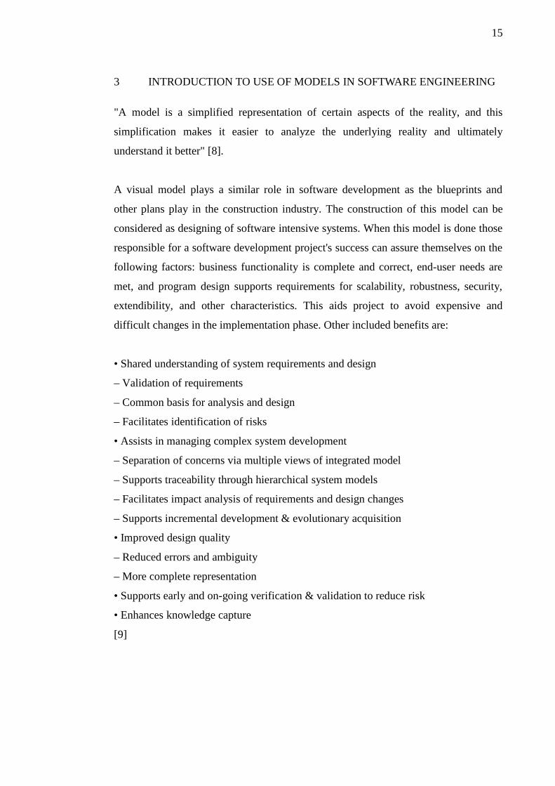
"A model is a simplified representation of certain aspects of the reality, and this
simplification makes it easier to analyze the underlying reality and ultimately
understand it better" [8].
A visual model plays a similar role in software development as the blueprints and
other plans play in the construction industry. The construction of this model can be
considered as designing of software intensive systems. When this model is done those
responsible for a software development project's success can assure themselves on the
following factors: business functionality is complete and correct, end-user needs are
met, and program design supports requirements for scalability, robustness, security,
extendibility, and other characteristics. This aids project to avoid expensive and
difficult changes in the implementation phase. Other included benefits are:
• Shared understanding of system requirements and design
– Validation of requirements
– Common basis for analysis and design
– Facilitates identification of risks
• Assists in managing complex system development
– Separation of concerns via multiple views of integrated model
– Supports traceability through hierarchical system models
– Facilitates impact analysis of requirements and design changes
– Supports incremental development & evolutionary acquisition
• Improved design quality
– Reduced errors and ambiguity
– More complete representation
• Supports early and on-going verification & validation to reduce risk
• Enhances knowledge capture
[9]

16
There are number of different modeling languages available, none of them being ideal
for every domain and project. The Unified Modeling Language is the most accepted
modeling language in the software industry and ISO standard. However, for complex
systems it's modeling capabilities are insufficient [10]. To address these shortcomings
extension to UML Systems Modeling Language (SysML) was created. In this thesis
SysML and particularly it's requirement and callout diagrams to extend the
capabilities of model are studied in Chapter 6. UML ELEMENTS AND THEIR
RELATIONS TO REQUIREMENTS. Another important aspect of defining software
that meets the customer expectations is business process modeling. To have this
aspect included in model another UML extension Eriksson-Penker Business Modeling
Profile is applied, this is discussed in detail in Chapter 4 MODELING BUSINESS
PROCESSES.
3.1 Introduction to Unified Modeling Language
The Unified Modeling Language (UML) is a family of graphical notations, which
provides system architects, software engineers, and other team members tools for
analysis, design, and implementation of software based systems as well as for
modeling business and similar processes. The UML helps engineers to specify,
visualize, and document models of software systems, including their structure and
design, in a way that meets all of these requirements.
The initial version of UML originated with three leading object-oriented methods
(Booch, OMT, and OOSE), and incorporated a number of best practices from
modeling language design, object-oriented programming, and architectural description
languages. Future revisions of UML have enhanced standard with significantly more
precise definitions of its abstract syntax rules and semantics, a more modular language
structure, and a greatly improved capability for modeling large-scale systems. [11]
In UML 2.0 it is possible to zoom out from a detailed view of an application to the
environment where it executes, visualizing connections to other applications.
Alternatively, it is possible to focus on different aspects of the application, such as the
Figure 2: UML 2.2 Diagram types

17
business process that it automates, or a business rules view. The new ability to nest
model elements supports this concept directly. [12]
Modeling almost about any type of application, running on any type and combination
of hardware, operating system, programming language, and network, is possible with
UML. It is built upon fundamental object orientation concepts including class and
operation, making it designed for object-oriented languages and environments but it
can also be used to model non- object oriented applications.
3.1.1 UML Diagrams
It is very important to distinguish between the UML model and the set of diagrams of
a system. A diagram is a partial graphical representation of a system's model. UML
diagrams represent two different views of a system model: Static (or structural) and
Dynamic (or behavioral). The static view emphasizes the static structure of the system
using objects, attributes, operations and relationships. The dynamic (or behavioral)
view emphasizes the dynamic behavior of the system by showing collaborations
among objects and changes in the internal states of objects.
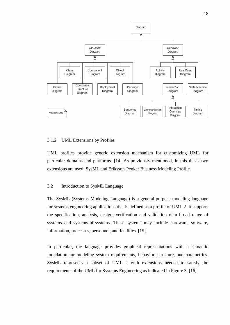
UML 2.2 has 14 types of diagrams divided into these two categories. Seven diagram
types represent structural information, and the other seven represent general types of
behavior, including four that represent different aspects of interactions. These
diagrams can be categorized hierarchically as shown in Figure 2. [13]
18
3.1.2 UML Extensions by Profiles
UML profiles provide generic extension mechanism for customizing UML for
particular domains and platforms. [14] As previously mentioned, in this thesis two
extensions are used: SysML and Eriksson-Penker Business Modeling Profile.
3.2 Introduction to SysML Language
The SysML (Systems Modeling Language) is a general-purpose modeling language
for systems engineering applications that is defined as a profile of UML 2. It supports
the specification, analysis, design, verification and validation of a broad range of
systems and systems-of-systems. These systems may include hardware, software,
information, processes, personnel, and facilities. [15]
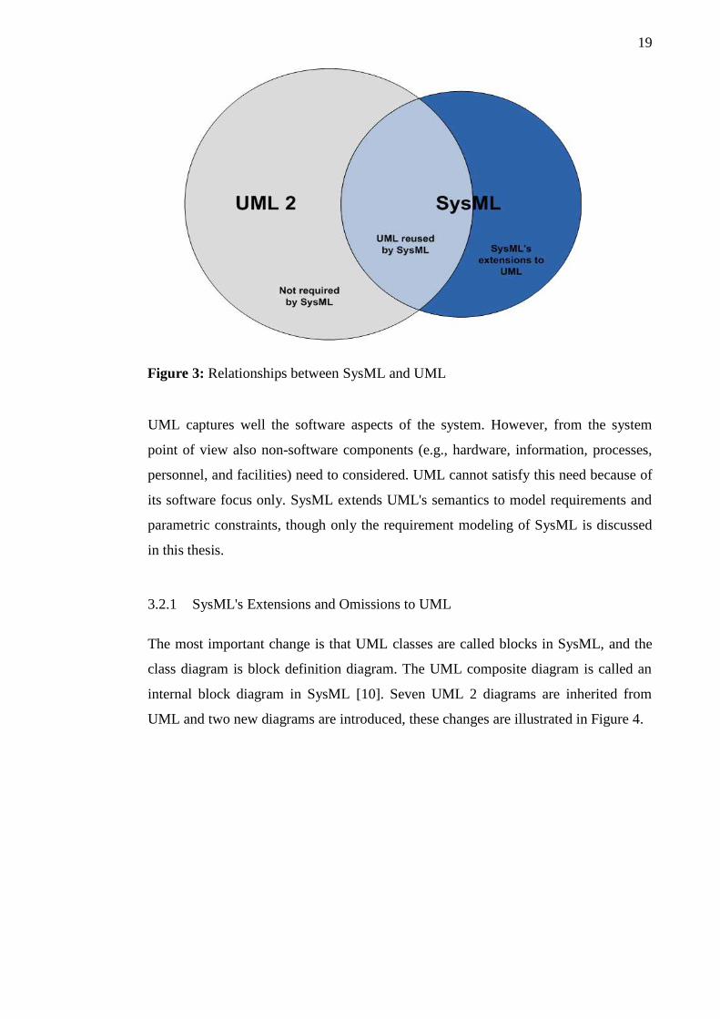
In particular, the language provides graphical representations with a semantic
foundation for modeling system requirements, behavior, structure, and parametrics.
SysML represents a subset of UML 2 with extensions needed to satisfy the
requirements of the UML for Systems Engineering as indicated in Figure 3. [16]
19
UML captures well the software aspects of the system. However, from the system
point of view also non-software components (e.g., hardware, information, processes,
personnel, and facilities) need to considered. UML cannot satisfy this need because of
its software focus only. SysML extends UML's semantics to model requirements and
parametric constraints, though only the requirement modeling of SysML is discussed
in this thesis.
3.2.1 SysML's Extensions and Omissions to UML
The most important change is that UML classes are called blocks in SysML, and the
class diagram is block definition diagram. The UML composite diagram is called an
internal block diagram in SysML [10]. Seven UML 2 diagrams are inherited from
UML and two new diagrams are introduced, these changes are illustrated in Figure 4.
Figure 3: Relationships between SysML and UML

20
SysML allocation tables support common kinds of allocations. Whereas UML
provides only limited support for tabular notations, SysML furnishes flexible
allocation tables that will support requirements allocation, functional allocation, and
structural allocation. This capability facilitates automated verification and validation
and gap analysis. This is discussed in detail in Chapter 6 UML ELEMENTS AND
THEIR RELATIONS TO REQUIREMENTS. With SysML it is possible to use
requirement diagrams to efficiently capture functional, performance and interface
requirements. If UML is solely used team is subject to the limitations of the Use Case
diagrams to define high-level functional requirements.
Figure 4: SysML Diagram Types

21
4 MODELING BUSINESS PROCESSES
4.1 Introduction
"Business processes are the activities that a commercial organisation performs in order
to carry out its business. All organisations depend for their competitiveness on the
efficiency with which their business processes operate" [17].
For any software project to achieve a commercial success over the bare technical code
complete, the solution provider must have a sufficient understanding about customer's
business processes. Unfortunately, this step is very often neglected and as a result the
software solutions are ill adjusted to support the customer's business, and instead of
being enablers in the business they tend to disable opportunities for a organisation.
This occurs because from the software provider side there is reluctance to study, so
called domain knowledge area of customer, and from customer side there is often lack
of interest to understand the software solutions [18]. Therefore, in order to narrow this
information gap and integrate the project's stakeholder's vision of the expected
outcome, modeling business processes is useful step before requirements engineering.
The extent of a needed research depends generally on the nature of the project: type,
size, complexity, criticality, and customer requirements and the chosen development
process of the software provider. For example ERP (Enterprise Resource Planning)
projects require intimate understanding of the customer's business [19]. In turn smaller
and simpler projects the time and energy spent analyzing customer's business process
can be minute [20]. Furthermore, good analyst understands that business process
model has a broader and more inclusive range than any software system being
considered. As a result, an effective business model allows clearly map the scope of
the proposed system as well as pieces of the process that must be implemented in
other ways, such as manual processes that the software system can not handle [21].

22
A business process model specification typically consist of the following elements:
• Goal of the process
• Specific inputs and outputs
• Used resources
• Events that drive or affect the process
• Activities and the order in which they are performed
Inputs and outputs often refer to data, but they can also be something that is processed
or worked upon. For example, a system requires data input and typically outputs data
in return: a report, a completed customer order, etc. Resources can be persons or parts
of a system that are involved in performing the activities. Events can be any number
of things, which trigger something that initiates a business process. For example a
deadline might trigger the start of an invoicing process. [22]
4.2 Selection of Modeling Language
When documenting the process it is very important to keep in mind that a business
process model must be in the type of a format that all stakeholders can understand it.
There exist a variety of ways to document business processes ranging from textual
descriptions to sophisticated models [21]. Four common uses of modeling languages
in business processes context are briefly introduced here: UML Use Cases, UML
Activity Diagram, Business Process Modeling Notation (BPMN), and UML Extension
Eriksson-Penker Business Modeling Profile (EPBE).
Firstly, project utilizing Rational Unified Software Development Process (RUP) or its
variants, which gives emphasis to use cases, would model processes through user
interactions alone. This can be sufficient way to describe them in many cases [21].
Secondly, the UML activity diagram can be applied to business process modeling. As
it states in the UML standard "Activities may be applied to organizational modeling
for business process engineering and workflow" [23]. But as brought out by a study
by Eloranta, Kallio, Terho (2006), the use of an activity diagram requires the modeler
to carefully select, which elements are appropriate for business modeling and it will
require the audience to be literate on the UML activity diagram notation [24].
23
Thirdly, Business Process Modeling Notation is widely used among the business
people and being designed for this sole purpose can indeed model the processes
accurately. It has it similarities to UML activity diagram but at least while writing this
these to modeling languages have not converged even though there is growing
pressure to align these two modeling languages [25].
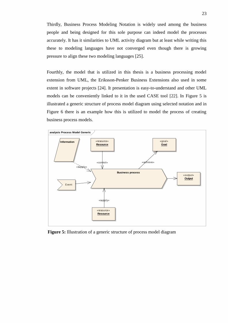
Fourthly, the model that is utilized in this thesis is a business processing model
extension from UML, the Eriksson-Penker Business Extensions also used in some
extent in software projects [24]. It presentation is easy-to-understand and other UML
models can be conveniently linked to it in the used CASE tool [22]. In Figure 5 is
illustrated a generic structure of process model diagram using selected notation and in
Figure 6 there is an example how this is utilized to model the process of creating
business process models.
Figure 5: Illustration of a generic structure of process model diagram
analysis Process Model Generic
Business process
Even t
«goal»Goal
Information
«outpu t»Output
«resource»Resource
«resource»Resource
«ach ieve»
«supply»
«supply»
«con tro l»

24
Figure 6 shows how the triggering event for the process is the need to understand the
domain aspects of the software project better. The principal stakeholder is a person
who acts as a Business Analyst who facilitates the process by taking the information
input (hierarchy charts, manuals, existing process definitions, etc.) and using the other
resources that contribute the process model creation (a team may consist of
department heads, experts, project leads, etc.). The goal is to accurately model the
business as it is or how the team wants it to be when the system is ready. This goal is
achieved by creating a business model diagram that contains relevant information.
analysis Process Model of Creation of Process Model
Business process of Creating Business Process Model
Requi rem ent team needs to understand
the dom a in aspects of the SW pro ject
«goa l»Accurate model that effectively describe
business logicHierarchy charts,
Manuals, Process
definitions, etc. «ou tput»
Business process model of a customer
in a form analysis diagram
«resource»Business Analyst
«resource»Team that contributes
business process modeling
«ach ieve»«con tro l»
«supp ly»
«supply»
Figure 6: Example showing how an analysis diagram is used to describe a processrelated to creating a model of business processes.
25
5 MODELING REQUIREMENTS
5.1 Definition of Requirement
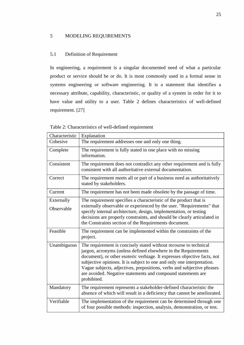
In engineering, a requirement is a singular documented need of what a particular
product or service should be or do. It is most commonly used in a formal sense in
systems engineering or software engineering. It is a statement that identifies a
necessary attribute, capability, characteristic, or quality of a system in order for it to
have value and utility to a user. Table 2 defines characteristics of well-defined
requirement. [27]
Table 2: Characteristics of well-defined requirement
Characteristic ExplanationCohesive The requirement addresses one and only one thing.
Complete The requirement is fully stated in one place with no missinginformation.
Consistent The requirement does not contradict any other requirement and is fullyconsistent with all authoritative external documentation.
Correct The requirement meets all or part of a business need as authoritativelystated by stakeholders.
Current The requirement has not been made obsolete by the passage of time.
Externally
Observable
The requirement specifies a characteristic of the product that isexternally observable or experienced by the user. "Requirements" thatspecify internal architecture, design, implementation, or testingdecisions are properly constraints, and should be clearly articulated inthe Constraints section of the Requirements document.
Feasible The requirement can be implemented within the constraints of theproject.
Unambiguous The requirement is concisely stated without recourse to technicaljargon, acronyms (unless defined elsewhere in the Requirementsdocument), or other esoteric verbiage. It expresses objective facts, notsubjective opinions. It is subject to one and only one interpretation.Vague subjects, adjectives, prepositions, verbs and subjective phrasesare avoided. Negative statements and compound statements areprohibited.
Mandatory The requirement represents a stakeholder-defined characteristic theabsence of which will result in a deficiency that cannot be ameliorated.
Verifiable The implementation of the requirement can be determined through oneof four possible methods: inspection, analysis, demonstration, or test.

26
In the classical engineering approach, sets of requirements are used as inputs into the
design stages of product development. When requirements are described manner
outlined in Table 2 they effectively show what elements and functions are necessary
for the particular project. [27]
In SysML standard [28] requirements are defined trough Requirement Diagram. A
requirement is defined as a stereotype of UML Class. The «requirement» stereotype
represents a text based requirement it includes id and text properties. Figure 7
illustrates this. It can be extended with user defined properties e.g. verification method
and user defined requirements categories (e.g. functional, interface, performance).
5.2 Requirements Relationships and Rationale
Several requirements relationships can be specified via stereotyped dependencies in
UML that enable the modeler to relate the requirements to other requirements as well
as to other model elements. The «deriveReqt» and «satisfy» dependencies describe the
derivation of requirements from other requirements and the satisfaction of
requirements by design, respectively. The «verify» dependency shows the link from a
test case to the requirement or requirements it verifies. In addition, the UML «refine»
dependency is used to indicate that an SysML model element is a refinement of a
textual requirement, and «a copy» relationship is used to show reuse of a requirement
within a different requirement hierarchy. [29]
The «rationale» concept can be used to annotate any model element to identify
supporting rationale including analysis and trade studies for a derived requirement, a
design or some other decision. A rationale is a SysML model element that can be
req sysML Example Require...
«requi rem ent»Requirement name
+ text = Description of ...+ id = 112
Figure 7: Simple example of SysML requirement diagram with one requirement

27
associated with either a requirement or a relationship between requirements. As the
name implies, the rationale is intended to capture the reason for a particular design
decision. Although rationale is described here for requirements, it is a model element
that can be applied throughout the model to capture the reason for any type of
decision. [28] Example of its usage can be seen in Figure 8.
A composite requirement can contain sub-requirements in terms of a requirements
hierarchy, specified using the UML namespace containment mechanism. This
relationship enables a complex requirement to be decomposed into its containing child
requirements. A composite requirement may state that the system shall do A and B
and C, which can be decomposed into the child requirements that the system shall do
A, the system shall do B, and the system shall do C. An entire specification can be
decomposed into children requirements, which can be further decomposed into their
children to define the requirements hierarchy. These relations ships are illustrated in
Figure 8.
The “derive requirement” relationship relates a derived requirement to its source
requirement. This typically involves an analysis to determine the multiple derived
req Example Requirement Relationships
Cl ient sha l l download l i ve T V m etadata from ded icated server
Requi red m etadata for cl ien t l ive T V service
Channel re la ted m etada
Channel logo
Channel ti tl e
Program re la ted m etadata
Program ti tle
Program genre
Program tim es (i .e . start and end tim e)
Program descrip tion
<<rationa le>> L ive T V M etadata is log ica l to sp l i t in to Channel and Program parts. Channel representing the provider (e .g . broadcaster) o f flow d i ffe rent program s. Program s present e .g . part o f T V series that wi l l be ava i lab le for viewing over certa in dura ta ion.
Figure 8: Composition of Live TV EPG client requirements and use of Rationale

28
requirements that support a source requirement. The derived requirements generally
correspond to requirements at the next level of the system hierarchy.
The satisfy relationship describes how a design or implementation model satisfies one
or more requirements. A system modeler specifies the system design elements that are
intended to satisfy the requirement.
The verify relationship defines how a test case or other model element verifies a
requirement. In SysML, a test case or other named element can be used as a general
mechanism to represent any of the standard verification methods for inspection,
analysis, demonstration, or test. Additional subclasses can be defined by the user if
required to represent the different verification methods. A verdict property of a test
case can be used to represent the verification result. The SysML test case is defined
consistent with the UML testing profile to facilitate integration between the two
profiles.
The refine requirement relationship can be used to describe how a model element or a
set of elements can be used to further refine a requirement. For example, a use case or
activity diagram may be used to refine a text-based functional requirement.
Alternatively, it may be used to show how a text-based requirement refines a model
element. In this case, some elaborated text could be used to refine a less fine-grained
model element.
A generic trace requirement relationship provides a general-purpose relationship
between a requirement and any other model element. The semantics of trace include
no real constraints and therefore are quite weak. As a result, it is recommended that
the trace relationship not be used in conjunction with the other requirements
relationships described above.

29
6 UML ELEMENTS AND THEIR RELATIONS TO REQUIREMENTS
After modeling business processes, use cases and requirements are usually
concurrently modeled. After this developers need to extend the design with diagrams
describing the structure of system i.e. architecture and other design aspects such as the
dynamics using e.g. sequence diagrams.
6.1 Use Cases
Use case diagrams are useful for requirements management when kept in mind that
they are good for capturing interaction between external user and the system.
However, there are not enough to describe exhaustively the non-functional
characteristic of the system.
The core of a use case description is about answering to a simple questions: who,
what, when and how, and being able to communicate this to the relevant stakeholders.
The who refers to one or more actors that interact with the system. The what describes
the actor's goal. The when refers to the pre- and post-requisites. When it can be started
and when it's completed. Finally, the how describes the scenario of events that are
needed to accomplish the goal. Figure 9 describes an example use case where 'Mobile
TV application downloads EPG information on it's start-up'.
Figure 9: Use case diagram describing intial download of EPG information

30
As can be seen in Figure 9 it is the user who starts the application which then triggers
the initial EPG download use case. Download of ongoing live TV show's metadata
information is accomplished (for reference see also Figure 8. Composition of Live TV
EPG client requirements and use of Rationale). Case is executed at the application
startup and it is completed when necessary EPG information has been downloaded. To
further define how this accompished, the expression power of use case can be
extended with a nested diagram such as sequence diagram.
6.2 Sequence Diagrams
A sequence diagram is an interaction diagram that shows how processes or objects
operate with one another and in what order. In parallel are vertical lines (lifelines),
they are different processes or objects that live simultaneously, and, as horizontal
arrows, the messages exchanged between them, in the order in which they occur. This
allows the specification of simple runtime scenarios in a graphical manner. Figure 10
is a nested sequence diagram that describes the interaction needed to download initial
EPG information. It describes how application components: main, user interface,
storage, EPG client communicate with EPG server to accomplish this goal.
Figure 10: Sequence diagram (nested element of use case) defining details of initialEPG download

31
6.3 Allocations and Callout diagram
Allocation is the term used by systems engineers to denote the organized cross-
association (mapping) of elements within the various structures or hierarchies of a
user model. The concept of “allocation” requires flexibility suitable for the abstract
system specification, rather than a particular constrained method of a system or a
software design. System modelers often associate various elements in a user model in
abstract, preliminary, and sometimes tentative ways. Allocations can be used early in
the design as a precursor to more detailed rigorous specifications and
implementations. The allocation relationship can provide an effective means for
navigating the model by establishing cross relationships, and ensuring the various
parts of the model are properly integrated. The callout notation is used when
requirements do not appear on other kinds of diagrams, or when other model elements
do not appear on a requirement diagram [28]. Figure 11 presents an example of this
where in the use case presented earlier is associated with the requirements that it
realizes.
Figure 11: Callout diagram describing how 'initial EPG download' use caseimplements the two sub-requirements of EPG download
32
7 CONCLUSIONS
7.1 UML Based Requirement Management Process
A typical requirement management process consists of several sub-processes:
elicitation, analysis, documentation (i.e. specification), validation, and change
control. This is valid also for the UML-RM process with the exception that
documentation is not really a separate activity, since in this UML-RM process the
model is created from beginning and updated constantly.
A requirement analyst is the main responsible for documentation efforts and the
principal owner of the requirement model [31]. Therefore, typically the analyst would
be the person that implements business process, use case, and requirement diagrams.
However, all users of the system model are applying, extending, and connecting to
these diagrams and their elements. Connecting the requirement model to a design
model is an essential to provide added value on understanding the problem to be
solved. The model that is one of the project outcomes owned by whole project team.
7.1.1 Elicitation
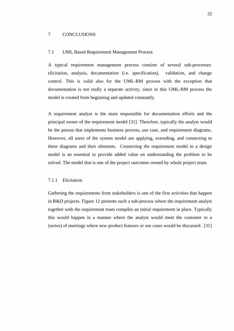
Gathering the requirements from stakeholders is one of the first activities that happen
in R&D projects. Figure 12 presents such a sub-process where the requirement analyst
together with the requirement team compiles an initial requirement in place. Typically
this would happen in a manner where the analyst would meet the customer in a
(series) of meetings where new product features or use cases would be discussed. [31]

33
An existing product's requirement specifications, market studies, customer requests
can help the analyst to determine what are the initial requirements for a software
product. A good analyst acts pro-actively to help the users to articulate the system
capabilities they need to meet their business objectives. Users naturally emphasize the
system’s functional requirements, but discussion is needed to include quality
attributes, performance goals, business rules, external interfaces and constraints.
A well done elicitation can significantly reduce the need for costly change requests
later in the project.
An organization must select how many times the elicitation sub-process happens in
the lifetime of the project: only once in the beginning of the project or at the start of
each iteration of development. If the development process is similar to the waterfall
model then it would be natural to try to describe all the requirements in one-time
effort and handle possible changes through a change control process. On the other
hand, if the selected process has relatively short iterations, then elicitation would be
happening in the beginning of each iteration.
Depending on the project complexity an output contains a varying number of business
processes, use case and requirement diagrams.
Figure 12: Requirement elicitation process diagram

34
7.1.2 Analysis
When elicitation is completed requirements need to be checked for completeness and
consistency. This sub-process is effectively a review process where the team inspects
the requirement model. Experts from development, testing and other functional areas
of project are involved in auditing and approving the requirement set.
In practice, this could be a scheduled meeting with given material (initial requirement
model) and time to give review comments that are discussed in the review meeting
where analyst could act as a chairperson and a secretary.
Review participants should look for derived requirements that are a logical
consequence of the customers requests, as well as hunting for those implicit
requirements that they expect but haven’t verbalized. Attention should be placed on
vague, weak words that cause ambiguity and confusion. Auditors should point out
conflicting requirements and areas that need more detail. Functional requirements
should be described in a suitable level of detail for the developers.
Figure 13: Requirement analysis process diagram

35
After one or more review meetings and approval from the customer and project
management the requirement model should be stable enough to be 'frozen' i.e. all the
new requirements or changes to existing ones are implemented under change control
process.
7.1.3 Validation
Analysis and validation sub-processes aim for the same goal: Ensuring that the
documented requirements satisfy the customer needs and that they are clear, complete,
correct, feasible, necessary, traceable, unambiguous, and verifiable. The subtle
distinction of the two sub-processes is in the time line of the activity. An analysis
needs to happen after elicitation without the existing design diagrams, code and test
cases. Whereas validation happens when the design model, implementation and test
model are at least partially ready. Figure 14 describes such a process.
In practice, the requirement model is validated by creating the development model
based on the analyzed requirement model. This is a joint effort of the developers,
Figure 14: Requirement validation process diagram

36
analyst, and project manager. Furthermore, there might arise a need to involve
customer or other stakeholders to support the process and adjust certain aspects.
This mapping of requirement model and development is discussed in Chapter 6. UML
ELEMENTS AND THEIR RELATIONS TO REQUIREMENTS. Typically
developers would create embedded sequence diagrams to use cases, testers would
create (system) test cases from use cases and UI designers would create flows based
on use cases and user interface related requirements, etc. Diagrams that describe
structural aspects (i.e. architecture) would be traced into requirement elements so each
module would be responsible for fulfilling the required to functionality. If those
connections were not to be found than either there would be a missing requirement or
redundant code in a system
A validated model accurately pictures the system and in the process of update the
project team can learn many things. Such as that the whole team can intimately
understand the relation between the implementation and the customer requirement.
Having a project team to work integrated for the same cause and avoiding duplicate
work is a challenge in all projects especially in multi-site and technically demanding
ones [32]. The requirement validation sub-process contributes enormously to the
integrity of project.
Furthermore, a properly validated model gives a strong promise that the product can
be built and delivered or if it actually reveals severe challenges it aids the project
management to realize the risk of failure earlier in the project.
7.1.4 Change Control
There are entire books on this topic alone, managing change in a controlled manor is
demanding in the pressures of project life. In the industry there is widely spread
culture for NOT accepting the self-evident fact that change causes impact. Typical
phenomena of this is a scope creep where for example customer pushes for scope
changes and would not accept the affect on the delivery time and budget. These can be
avoided if the agreement for the project specifies a change control process. An
example of such a process is presented in Figure 15.
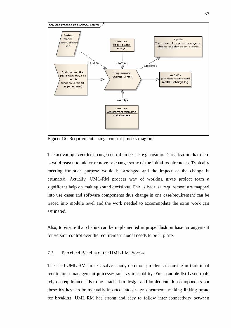
37
The activating event for change control process is e.g. customer's realization that there
is valid reason to add or remove or change some of the initial requirements. Typically
meeting for such purpose would be arranged and the impact of the change is
estimated. Actually, UML-RM process way of working gives project team a
significant help on making sound decisions. This is because requirement are mapped
into use cases and software components thus change in one case/requirement can be
traced into module level and the work needed to accommodate the extra work can
estimated.
Also, to ensure that change can be implemented in proper fashion basic arrangement
for version control over the requirement model needs to be in place.
7.2 Perceived Benefits of the UML-RM Process
The used UML-RM process solves many common problems occurring in traditional
requirement management processes such as traceability. For example list based tools
rely on requirement ids to be attached to design and implementation components but
these ids have to be manually inserted into design documents making linking prone
for breaking. UML-RM has strong and easy to follow inter-connectivity between
Figure 15: Requirement change control process diagram

38
requirement, design, and software components. This allows managers to check which
implementation component is responsible of what requirement. This again reduces
wasted effort on the project and makes teams and product more integrated.
Modeling also allows team to check the design before costly implementation work is
started reducing risk and wasted effort.
7.3 Limitations of the UML-RM Process
Since this process is based on UML notation it requires a project team to understand
the relevant diagrams. For example a customer is required to understand only simple
use case and requirement diagrams. Addition to these two diagrams project
management should also understand basic structural diagrams describing the
architecture. Whereas the developers should know how to apply for example sequence
diagrams to model interaction between components and class diagrams to specify the
system. UML is widely taught in universities so many professionals are familiar with
it. As a practical note requirement analyst might still need to act as a instructor to the
customer about the use case and requirement diagram notation when performing
requirement elicitation.
UML-RM is applicable to any implementation language and fitting for many
development processes and types of projects. The presented process is a custom fusion
of existing Use Case driven (ICONIX) and SysML methodologies. It applies well in
the software development areas were complexity is high for example multimedia
system projects.

39
REFERENCES
[1] Software Engineering. March 1, 2010 [online].
http://en.wikibooks.org/wiki/Software_Engineering
[2] Alain, Abran and James, Moore. Guide to the Software Engineering Body of
Knowledge (SWEBOK 2004). IEEE. March 1, 2010 [online].
http://www.computer.org/portal/web/swebok/htmlformat
[3] Bashar, Nuseibeh and Steve, Easterbrook. Requirements Engineering: A
Roadmap. 2000.
http://mcs.open.ac.uk/ban25/papers/sotar.re.pdf
[4] Wikipedia. Requirements management. March 1, 2010 [online].
http://en.wikipedia.org/wiki/Requirements_management
[5] The Standish Group. Report: CHAOS. 1995. April 13, 2010 [online].
http://www.projectsmart.co.uk/docs/chaos-report.pdf
[6] Wikipedia. IBM Rational Unified Process. April 13, 2010 [online].
http://en.wikipedia.org/wiki/IBM_Rational_Unified_Process
[7] Karl E. Wiegers. Requirements When the Field Isn’t Green. April 27, 2010
[online].
http://www.processimpact.com/articles/reqs_not_green.pdf
[8] Benoît Marchal. Working XML: UML, XMI, and code generation, Part 4. May
11, 2010 [online].
http://www.ibm.com/developerworks/xml/library/x-wxxm26/
[9] Sanford Friedenthal, Alan Moore, and Rick Steiner. Object Management
Group. OMG Systems Modeling Language (OMG SysML™) Tutorial. May 11,
2010 [online].
http://www.omgsysml.org/INCOSE-2008-OMGSysML-Tutorial-Final-revb.pdf
40
[10] Tim Weilkiens. Systems engineering with SysML/UML: modeling, analysis,
design. Morgan Kaufmann. 2007.
[11] OMG Unified Modeling Language, Infrastructure. Version 2.2. February 2009.
May 11, 2010 [online]
http://www.omg.org/spec/UML/2.2/Infrastructure/PDF/
[12] Object Management Group. Introduction To OMG's Unified Modeling
Language. July 2005. May 11, 2010 [online].
http://www.omg.org/gettingstarted/what_is_uml.htm
[13] Wikipedia. Unified Modeling Language. May 11, 2010 [online].
http://en.wikipedia.org/wiki/Unified_Modeling_Language
[14] Wikipedia. Profile (UML). May 11, 2010 [online].
http://en.wikipedia.org/wiki/Profile_(UML)
[15] SysML FAQ. May 11, 2010 [online].
http://www.sysmlforum.com/FAQ.htm
[16] The Official OMG SysML site. May 11, 2010 [online].
http://www.omgsysml.org/
[17] Peter Henderson. Systems engineering for business process change:
collected papers from the EPSRC research programme: Business Processes,
Legacy Systems and a Fully Flexible Future. Page 2. Springer. 2000.
[18] Sten and Per Sundblad. Requirements Management
Software Directory. Microsoft Architect Journal: Business Improvement
Through Better Software Architecture. May 11, 2010 [online].
http://msdn.microsoft.com/en-us/library/bb266336.aspx
[19] Štemberger, Mojca Indihar and Kovacic, Andrej. The Role

41
of Business Process Modelling in ERP Implementation Projects.
This paper appears in: Computer Modeling and Simulation, 2008. UKSIM 2008.
Publication Date: 1-3 April 2008. pages: 260-265.
[20] Mohan Babu K. Is IT-Business/Domain Knowledge overrated? May 11, 2010
[online].
http://www.infosysblogs.com/managing-offshore-
it/2007/02/is_businessdomain_knwledge_ove_1.html
[21] IBM. Slack Sally. Understanding business process modeling. August 2008. May
11, 2010 [online].
http://download.boulder.ibm.com/ibmdl/pub/software/dw/
architecture/ar-undprocmod/ar-undprocmod-pdf.pdf
[22] Sparx Systems. UML TUTORIALS: THE BUSINESS PROCESS MODEL. May
11, 2010 [online].
http://www.sparxsystems.com/downloads/whitepapers/
The_Business_Process_Model.pdf
[23] OMG Unified Modeling Language, Superstructure. Version 2.2. p. 332.
February 2009. May 18, 2010 [online]
http://www.omg.org/spec/UML/2.2/Superstructure/PDF/
[24] Eloranta, Kallio, and Terho: A Notation Evaluation of BPMN and UML AD.
2006. May 18, 2010 [online]
http://www.soberit.hut.fi/T-86/T-86.5161/2006/BPMN_vs_UML_final.pdf
[25] IBM. Steven A. White. Process Modeling Notations and Workflow Patterns.
BPTrends. March, 2004. May 18, 2010 [online]
http://www.bptrends.com/publicationfiles/03-04%20WP%20Notations%20and
%20Workflow%20Patterns%20-%20White.pdf
[26] Gurau, Calin. Restructuring the Marketing Information System for eCRM:
An Application of the Eriksson-Penker Method.

42
[27] Wikipedia. Requirement. May 18, 2010 [online].
http://en.wikipedia.org/wiki/Requirement
[28] OMG Systems Modeling Language (OMG SysML™). Version 1.1.
November 2008. July 26, 2010 [online]
http://www.omg.org/spec/SysML/1.1/changebar/PDF/
[29] Matthew Hause. The SysML Modelling Language.
September 2006. July 26, 2010 [online].
http://www.omgsysml.org/The_SysML_Modelling_Language.pdf
[30] Sanford, Friedenthal; Alan, Moore and Rick Steiner. A Practical Guide to
SysML: The Systems Modeling Language. Morgan Kaufmann. 2008.
[31] Karl E. Wiegers. So You Want To Be a Requirements Analyst? 2003. July 27,
2010 [online].
http://www.processimpact.com/articles/be_analyst.pdf
[32] Harold, Kerzner. Project Management: A Systems Approach to Planning,
Scheduling. and Controlling. Ninth Edition. Wiley. 2006.