Towards 100 Gigabit Carrier Ethernet Transport Networks
12
Towards 100 Gigabit Carrier Ethernet Transport Networks A. RASMUSSEN, J. ZHANG, H. YU, R. FU, S. RUEPP, H. WESSING, M. BERGER DTU Fotonik Technical University of Denmark DTU Bldg. 343, DK-2800 Kgs. Lyngby DENMARK [email protected] http://www.fotonik.dtu.dk Abstract: - Ethernet as a transport technology has, up to now, lacked the features such as network layer architecture, customer separation and manageability that carriers require for wide-scale deployment. However, with the advent of PBB-TE and T- MPLS, it is now possible to use Ethernet as a transport technology, making the use of Ethernet as a convergence layer for Next Generation Networks a distinct possibility. Triple Play services, in particular IPTV, are expected to be a main drivers for carrier Ethernet, however, a number of challenges must be addressed including QoS enabled control plane, enhanced OAM functions, survivability and the increased bandwidth requirements of carrier class systems. This article provides an overview of PBB-TE and T-MPLS and demonstrates how IPTV services can be realized in the framework of Carrier Ethernet. In addition we provide a case study on performing bit error rate (BER) measurements on the aggregated 100G stream. Key-Words: - Carrier Ethernet, IPTV, T-MPLS, PBB-TE, NGN, BERT, 100G 1 Introduction For many years, the telecommunication service providers have been looking for new ways to compensate the declining revenue on the plain old telephone service and broadband access. The next big step that can deliver a substantial increase in revenue is believed to be the introduction of IPTV. As a response to the increased interest in television via the Internet (IPTV) the Danish Advanced Technology Foundation decided to finance two new research projects entitled High quality IP network for IPTV and VOIP (HIPT) and “The Road to 100 Gigabit Ethernet” (100G) respectively. The objective of the HIPT project is to enhance carrier Ethernet transport for IPTV applications by developing technology that can fulfill the increasing requirements in terms of quality while reducing the cost of network operation. The 100G project is mainly focused on the task of switching Carrier Ethernet traffic with carrier class QoS and monitoring functionality as well as carrying out performance measurements on such systems. This should all be done at the unprecedented speed of 100Gbps corresponding to more than 148 million MAC frames per second. Metro Ethernet forum (MEF) has provided a clear definition of carrier Ethernet in relation to Ethernet services. Ac- cording to MEF, a Carrier Ethernet service and the underlying equipment supporting the service must possess the following attributes: Standardized services, Scalability, reliability, Quality of Service and Service management. This article provides in section 2 an overview of Carrier Ethernet transport technology with focus on Traffic Engineered Provider Backbone Transport (PBB-TE), Transport-MPLS (T-MPLS) and the internal Physical Coding Sublayer (PCS) for 100G Ethernet. Following that, in section 3, the high level network architecture for IPTV transport over Carrier Ethernet adopted by the HIPT project is introduced. Section 4 lists the main research challenges envisaged by the HIPT and 100G projects to make Carrier Ethernet comply with IPTV transport in terms of functionality, quality and bandwidth. Finally, we present a case study on the challenges of performing bit error rate measurements on the aggregated 100G stream over a 100 Gigabit Media Independent Interface (CGMII). The main areas for further research are identified and solutions as well as future directions are given. 2 Carrier Ethernet Technology Telecom carriers have spent more than 10 years developing a Next Generation Network concept that will allow them to simultaneously deliver packet-based and circuit-based services. It is now widely accepted that the Internet Protocol (IP) will form the basis for new services, as well as assist in the transition of circuit-based services to packet-based services (e.g. Voice and Video over IP). However, it is far from certain that IP routing technology will be adopted as the transport convergence layer. IP/MPLS has been widely deployed, especially in carrier backbone/core networks as a service layer and as a convergence layer, but Ethernet is fast becoming a credible alternative candidate. 95% of all data traffic either originates or terminates as Ethernet, and data volume is forecast to grow tremendously WSEAS TRANSACTIONS on COMMUNICATIONS ISSN: 1109-2742 153 Issue 3, Volume 9, March 2010
Transcript of Towards 100 Gigabit Carrier Ethernet Transport Networks
Towards 100 Gigabit Carrier Ethernet Transport Networks A. RASMUSSEN, J. ZHANG, H. YU, R. FU, S. RUEPP, H. WESSING, M. BERGER
DTU Fotonik Technical University of Denmark
DTU Bldg. 343, DK-2800 Kgs. Lyngby DENMARK
[email protected] http://www.fotonik.dtu.dk
Abstract: - Ethernet as a transport technology has, up to now, lacked the features such as network layer architecture, customer separation and manageability that carriers require for wide-scale deployment. However, with the advent of PBB-TE and T-MPLS, it is now possible to use Ethernet as a transport technology, making the use of Ethernet as a convergence layer for Next Generation Networks a distinct possibility. Triple Play services, in particular IPTV, are expected to be a main drivers for carrier Ethernet, however, a number of challenges must be addressed including QoS enabled control plane, enhanced OAM functions, survivability and the increased bandwidth requirements of carrier class systems. This article provides an overview of PBB-TE and T-MPLS and demonstrates how IPTV services can be realized in the framework of Carrier Ethernet. In addition we provide a case study on performing bit error rate (BER) measurements on the aggregated 100G stream. Key-Words: - Carrier Ethernet, IPTV, T-MPLS, PBB-TE, NGN, BERT, 100G 1 Introduction For many years, the telecommunication service providers have been looking for new ways to compensate the declining revenue on the plain old telephone service and broadband access. The next big step that can deliver a substantial increase in revenue is believed to be the introduction of IPTV. As a response to the increased interest in television via the Internet (IPTV) the Danish Advanced Technology Foundation decided to finance two new research projects entitled High quality IP network for IPTV and VOIP (HIPT) and “The Road to 100 Gigabit Ethernet” (100G) respectively. The objective of the HIPT project is to enhance carrier Ethernet transport for IPTV applications by developing technology that can fulfill the increasing requirements in terms of quality while reducing the cost of network operation. The 100G project is mainly focused on the task of switching Carrier Ethernet traffic with carrier class QoS and monitoring functionality as well as carrying out performance measurements on such systems. This should all be done at the unprecedented speed of 100Gbps corresponding to more than 148 million MAC frames per second. Metro Ethernet forum (MEF) has provided a clear definition of carrier Ethernet in relation to Ethernet services. Ac-cording to MEF, a Carrier Ethernet service and the underlying equipment supporting the service must possess the following attributes: Standardized services, Scalability, reliability, Quality of Service and Service management. This article provides in section 2 an overview of Carrier
Ethernet transport technology with focus on Traffic Engineered Provider Backbone Transport (PBB-TE), Transport-MPLS (T-MPLS) and the internal Physical Coding Sublayer (PCS) for 100G Ethernet. Following that, in section 3, the high level network architecture for IPTV transport over Carrier Ethernet adopted by the HIPT project is introduced. Section 4 lists the main research challenges envisaged by the HIPT and 100G projects to make Carrier Ethernet comply with IPTV transport in terms of functionality, quality and bandwidth. Finally, we present a case study on the challenges of performing bit error rate measurements on the aggregated 100G stream over a 100 Gigabit Media Independent Interface (CGMII). The main areas for further research are identified and solutions as well as future directions are given.
2 Carrier Ethernet Technology Telecom carriers have spent more than 10 years developing a Next Generation Network concept that will allow them to simultaneously deliver packet-based and circuit-based services. It is now widely accepted that the Internet Protocol (IP) will form the basis for new services, as well as assist in the transition of circuit-based services to packet-based services (e.g. Voice and Video over IP). However, it is far from certain that IP routing technology will be adopted as the transport convergence layer. IP/MPLS has been widely deployed, especially in carrier backbone/core networks as a service layer and as a convergence layer, but Ethernet is fast becoming a credible alternative candidate. 95% of all data traffic either originates or terminates as Ethernet, and data volume is forecast to grow tremendously
given the impact of new video services and IPTV, for example. This situation has prompted many telecom carriers to consider Ethernet as a potential convergence solution for Next Generation Networks. With its scalability, ubiquity and natural support for IP services, Ethernet provides a compelling case. But before Ethernet can be adopted, it must be capable of supporting multiple services with at least the same level of quality as existing carrier services. In other words Ethernet must achieve a carrier grade of quality. 2.1 Provider Backbone Transport IEEE has developed a number of standards providing enhancements to the original Ethernet standards (dating from over 30 years ago). These include [1-5]: 802.1Q: Virtual LAN 802.1ad: Provider Bridging 802.1ah: Provider Backbone Bridging (draft) 802.3ah: Ethernet in the First Mile (with OAM) 802.1ag: Connectivity Fault Management (OAM) PBB-TE builds upon these standards to provide a network solution designed specifically for transport applications. PBB-TE creates an independent connection-oriented packet-switched transport layer. This allows various services, not necessarily limited to Ethernet services, to be transported transparently through the network. The following sections will concentrate on key features, which form the foundation of PBB-TE operation. 2.1.1 Provider Bridging (PB) 802.1Q VLAN capabilities were originally developed to provide a logical division of the same physical Ethernet network. However, only a limited range of possible VLAN instances was defined (4094 to be precise). This is the so-called “Single Tag”. In order to improve scalability, equipment vendors added support for a second VLAN tag. The resulting “Q-in-Q” or “Double Tagging” mechanism has been formalized in the IEEE 802.1ad Provider Bridging revision to 802.1Q. The inner tag field or C-Tag, see Figure 1, carries the customer VLAN Identifier (C-VID), which identifies a customer VLAN (C-VLAN). The outer tag field, or S-Tag, carries the S-VID, which identifies a service VLAN (S-VLAN). This tag is used to identify a service instance and defines a topological partition of the network based on the topology of this service instance. Spanning tree protocol is used to prevent loops in each S-VLAN (and independently, to prevent loops in each C-VLAN). S-VLAN provides customer separation and also isolation of customers from a carrier's network. However, the S-VLAN tag is itself too limited for large-scale carrier networks (ie. more than 4000 customers).
2.1.2 Independent VLAN Learning As the name suggests, with IVL there is an independent MAC address table for each VLAN. Forwarding is based both on the VLAN and destination MAC address. With IVL the MAC address table is local to a specific VLAN, which allows isolation of addressing within a customer or service VLAN instance. Double tagging can be used with Independent-VLAN-Learning (IVL), defined in 802.1Q. However, the tag space limits the number of S-VLAN to 4094, which limits the number of service instances that can be deployed in a single network. Thus, Ethernet's scalability problem remains. A consequence of partitioning the single Ethernet layer network is that S-VLAN specific state must be maintained by all switches in the network, which further limits scalability. In addition, VLANs are assigned across all ports in a switch, so reuse of VLAN IDs on different links is not possible. 2.1.3 Provider Backbone Bridging (PBB) PBB (also known as MAC-in-MAC) encapsulation adds layer-networking support to Ethernet. MAC-in-MAC encapsulation is now being formalized in the 802.1ah 'Provider Backbone Bridges' draft standard. Client PB Ethernet frames are encapsulated and forwarded in the backbone network based on new B-DA, B-SA and B-VID backbone-destination-address, backbone-source-address, and backbone-VLAN-ID fields. MAC-in-MAC encapsulation support improves upon the separation and isolation features introduced in 802.1ad: it supports complete isolation of individual client-addressing fields as well as isolation from address fields used in the operator's backbone. 802.1ah also introduces a new 24 bit tag field; the I-SID service instance identifier. This 24-bit tag field is proposed as a solution to the scalability limitations encountered with the 12 bit S-VID defined in Provider Bridges. 802.1ah Provider Backbone Bridges operate the same way as traditional Ethernet bridges. Service is still connectionless, flooding is used when destination MAC addresses are not recognized, and spanning tree is used to prevent loops. VLAN tags are reserved on a network, rather than a per-port basis.
WSEAS TRANSACTIONS on COMMUNICATIONSA. Rasmussen, J. Zhang, H. Yu, R. Fu, S. Ruepp, H. Wessing, M. Berger
ISSN: 1109-2742 154 Issue 3, Volume 9, March 2010
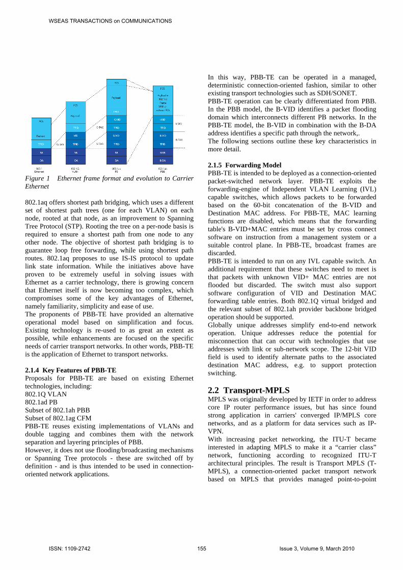
Figure 1 Ethernet frame format and evolution to Carrier Ethernet 802.1aq offers shortest path bridging, which uses a different set of shortest path trees (one for each VLAN) on each node, rooted at that node, as an improvement to Spanning Tree Protocol (STP). Rooting the tree on a per-node basis is required to ensure a shortest path from one node to any other node. The objective of shortest path bridging is to guarantee loop free forwarding, while using shortest path routes. 802.1aq proposes to use IS-IS protocol to update link state information. While the initiatives above have proven to be extremely useful in solving issues with Ethernet as a carrier technology, there is growing concern that Ethernet itself is now becoming too complex, which compromises some of the key advantages of Ethernet, namely familiarity, simplicity and ease of use. The proponents of PBB-TE have provided an alternative operational model based on simplification and focus. Existing technology is re-used to as great an extent as possible, while enhancements are focused on the specific needs of carrier transport networks. In other words, PBB-TE is the application of Ethernet to transport networks.
2.1.4 Key Features of PBB-TE Proposals for PBB-TE are based on existing Ethernet technologies, including: 802.1Q VLAN 802.1ad PB Subset of 802.1ah PBB Subset of 802.1ag CFM PBB-TE reuses existing implementations of VLANs and double tagging and combines them with the network separation and layering principles of PBB. However, it does not use flooding/broadcasting mechanisms or Spanning Tree protocols - these are switched off by definition - and is thus intended to be used in connection-oriented network applications.
In this way, PBB-TE can be operated in a managed, deterministic connection-oriented fashion, similar to other existing transport technologies such as SDH/SONET. PBB-TE operation can be clearly differentiated from PBB. In the PBB model, the B-VID identifies a packet flooding domain which interconnects different PB networks. In the PBB-TE model, the B-VID in combination with the B-DA address identifies a specific path through the network,. The following sections outline these key characteristics in more detail. 2.1.5 Forwarding Model PBB-TE is intended to be deployed as a connection-oriented packet-switched network layer. PBB-TE exploits the forwarding-engine of Independent VLAN Learning (IVL) capable switches, which allows packets to be forwarded based on the 60-bit concatenation of the B-VID and Destination MAC address. For PBB-TE, MAC learning functions are disabled, which means that the forwarding table's B-VID+MAC entries must be set by cross connect software on instruction from a management system or a suitable control plane. In PBB-TE, broadcast frames are discarded. PBB-TE is intended to run on any IVL capable switch. An additional requirement that these switches need to meet is that packets with unknown VID+ MAC entries are not flooded but discarded. The switch must also support software configuration of VID and Destination MAC forwarding table entries. Both 802.1Q virtual bridged and the relevant subset of 802.1ah provider backbone bridged operation should be supported. Globally unique addresses simplify end-to-end network operation. Unique addresses reduce the potential for misconnection that can occur with technologies that use addresses with link or sub-network scope. The 12-bit VID field is used to identify alternate paths to the associated destination MAC address, e.g. to support protection switching.
2.2 Transport-MPLS MPLS was originally developed by IETF in order to address core IP router performance issues, but has since found strong application in carriers' converged IP/MPLS core networks, and as a platform for data services such as IP-VPN. With increasing packet networking, the ITU-T became interested in adapting MPLS to make it a “carrier class” network, functioning according to recognized ITU-T architectural principles. The result is Transport MPLS (T-MPLS), a connection-oriented packet transport network based on MPLS that provides managed point-to-point
WSEAS TRANSACTIONS on COMMUNICATIONSA. Rasmussen, J. Zhang, H. Yu, R. Fu, S. Ruepp, H. Wessing, M. Berger
ISSN: 1109-2742 155 Issue 3, Volume 9, March 2010

connections to different client layer networks (such as Ethernet). However, unlike MPLS, it does not support a connectionless mode and is intended to be simpler in scope, less complex in operation and more easily managed. Layer 3 features have been eliminated and the control plane uses a minimum of IP - this should lead to equipment implementations that support carriers' needs for lower-cost, high-volume packet networking in their next-generation architectures.
Figure 2 Example T-MPLS network architecture T-MPLS is formulated in conjunction with today's circuit-based transport networks, following the same architectural, management and operational models. It is thus intended to provide an optimum evolution path for many carriers in their metro and access networks, as they transition to a packet-based future. 2.2.1 T-MPLS Standardization ITU-T Study Group 15 has been standardizing the definition of T-MPLS since early 2005, with the stated objective of identifying a subset of existing MPLS necessary and sufficient to provide connection oriented packet transport. T-MPLS is initially focused on supporting Ethernet services but the client/server architecture can handle all packet services, including IP/MPLS, in concert with SDH/OTH circuit services. One of the main definition goals of T-MPLS was to be aligned with ITU-T Recommendations G.805 and G.809 [6] [7] which themselves define a layered network architecture model for today's transport networks. This standardization approach has been supported by a number of leading systems houses, with a combined market share of well over 70% of the WDM/SDH transport equipment market and indeed some early and target product platforms are already on the commercial market. In 2006, ITU-T approved the first three Recommendations on Transport MPLS after various developments during the year in co-operation with IETF and MFA Forum. These three documents are: • G.8110.1: Architecture of Transport MPLS (T-MPLS) Layer Network; • G.8112: Interfaces for the Transport MPLS (T-MPLS) Hierarchy (TMH);
• G.8121: Characteristics of multi-protocol label switched (MPLS) equipment functional blocks. T-MPLS scope is large and further standardization work is ongoing, including: • New amendment to G.8110.1, due for consent in 2007; • OAM requirements and mechanisms (G.8113, G.8114), also scheduled for consent in 2007; • Linear and ring protection methodologies (G.8131,G.8132); • IETF T-MPLS work under the moniker “draft-bryantpwe3-mpls-transport-00.txt” in the PWE3 WG 2.2.2 Definition of T-MPLS T-MPLS might best be described as a transport network profile of IETF RFCs and G.8110 (the ITU-T's definition of MPLS), and is defined as a strictly connection-oriented subset of MPLS, meaning that: • Forwarding behavior of T-MPLS is a subset of IETF defined MPLS. This common data/forwarding plane retains the essential nature of MPLS and ensures that interoperability and interworking will be readily achievable. • Survivability is specific to the transport network. See section on Resiliency and survilability • OAM is specific to the transport network and functionality is referenced from ITU-T's Y.1711 (OAM mechanism for MPLS networks). • T-MPLS control plane (specific for the transport network) is currently null. In other words, the management plane will be used for manual/automated provisioning, in the same way as SDH and OTN/WDM networks are provisioned today. • No label reservation. That is, T-MPLS will not reserve labels for its own use independently of MPLS. Any requirements for special label assignment will be handled by IETF and co-ordinated with the MPLS standards. Again, this helps to ensure that interoperability and interworking will be readily achievable. 2.2.3 Differences from MPLS In order to define a subset of MPLS that is connection-oriented and that can be readily dealt with using the established transport OAM model, several MPLS protocol features have been excluded from T-MPLS. Key differences of T-MPLS compared with MPLS include: • Use of bi-directional LSPs (Label Switched Paths). Whilst MPLS LSPs are uni-directional, transport networks conventionally provision bi-directional connections. T-MPLS therefore pairs the forward and backward LSPs to follow the same nodes and links. • No PHP (Penultimate Hop Popping) option. PHP, by removing the MPLS label one node before the egress node, simplifies the egress processing required. Indeed, it comes from a historical legacy of wanting to minimize router
WSEAS TRANSACTIONS on COMMUNICATIONSA. Rasmussen, J. Zhang, H. Yu, R. Fu, S. Ruepp, H. Wessing, M. Berger
ISSN: 1109-2742 156 Issue 3, Volume 9, March 2010
processing requirements. However, the interface now has a mix of IP and MPLS packets and the final node must perform an IP (or other payload) look-up instead. More importantly, OAM is more complex or even impossible since the MPLS label context is lost. • No LSP Merging option. LSP Merge means that all traffic forwarded along the same path to the same destination may use the same MPLS label. Whilst this may promote scalability, in fact it makes effective OAM and Performance Monitoring (PM) difficult or even impossible, since the traffic source becomes ambiguous and unknown. It is thus not a connection-oriented concept. • No ECMP (Equal Cost Multiple Path) option. ECMP allows traffic within one LSP to be routed along multiple network paths. Not only does this require additional IP header processing, as well as MPLS label processing, but it makes OAM more complex since Continuity Check (CC) and PM flows may follow different paths. This concept is not needed in a connection-oriented network. 2.3 Standardisation of 100 Gigabit Ethernet The 100 gigabit Ethernet standard has been under development for quite some time as is still only available in a draft version. The following section describes some of the basics of the PCS layer and the CGMII interface in accordance to draft version 2.1 from May 2009 [9].
2.3.1 100G Media Independent Interface Similar to the 10G standard, the 100G draft standard specifies a Media Independent Interface (MII) for interconnecting the PHY and the MAC. The new 100G interface is very similar to the 10G MII (XGMII) interface standard, using the same control sequences to indicate Error (/E), Start-Of-Frame (SOF), End-Of-Frame (EOF) and Idle characters. However, a number of simplifications have been made to the new interface compared to the 10G version. In contrast to the XGMII interface, which is 4 byte aligned, the new 100G MII (CGMII) interface is 8 byte aligned i.e. it uses 8 byte words. This impacts functions such as SOF detection, since this character can only appear in the 1st byte position of the 8 byte word. Similarly, Idle sequences after the word containing the EOF character can only be a multiple of 8 bytes. Another restriction is placed on the occurrence of Error characters within the payload. Where XGMII allowed for single error characters everywhere in the binary data, the CGMII interface does not support single error characters in between the data bytes in the frame payload. Hence, if an error is detected in an 8 byte data word, the standard dictates that the entire word should be decoded as error characters. This is due to the 64b/66b encoding format, which unlike the 8b/10b encoding (see
2.3.2) does not allow the decoder to detect single byte or character errors in the payload.
2.3.2 100G Attachment Unit Interface As was the case for the XGMII interface, the pin count of the CGMII interface makes it an unviable solution for chip-to-chip or board-to-board communications. Hence, when communicating between devices, such as the MAC and the PHY a more serialized Attachment Unit Interface (AUI) is used. For the 10G AUI (XAUI), this interface was comprised of four individual physical lanes, each running at 3.125Gbps using 8b/10b encoding. The 100G AUI (CAUI) builds on the same concept, but utilizes 64b/66b rather than 8b/10b encoding to reduce the coding overhead. The CAUI also introduces the concept of “virtual lanes”. Instead of splitting the traffic onto 4 physical lanes, the CAUI distributes the 66b blocks direction between 20 virtual lanes. Splitting the traffic onto 20 lanes makes it possible to adapt the output to several bus-width/line-speed combinations by simple multiplexing, such as 4x25G or 10x10G, depending on the physical output device. In order to keep the different lanes correctly aligned, the XAUI uses a special 8b/10b encoded character, which is sent periodically over all lanes simultaneously. The receiving XAUI uses these alignment characters to verify, that all lanes are properly aligned and to correct the problem, should a misalignment occur. CAUI uses a similar approach, but has extended the alignment markers to fill up an entire 66b codeword on each virtual lane. Aside from a known three byte sequence, which is unique to each individual lane, the alignment markers also include a BIP8 even parity check sum calculated over all the 66b words from and including the last alignment marker. The last four bytes in the alignment marker is simply the inverse of the first four bytes, thus ensuring proper DC balance. A final difference, which we will point out, is the fact that the CAUI uses a scrambler in order to guarantee DC balance and transition density over the 66b words. The first two bits, which determine if the word is a control word or a data word, are kept unscrambled, as are the alignment markers. 3 IPTV over Carrier Ethernet Layer 3 and IP have proven useful in addressing Internet and other best effort data applications, however, this approach is not well suited to high-bandwidth, critical services, such as IPTV, which, in general, cannot tolerate delays in the network [16]. In the HIPT project, we intend to investigate whether more intelligent layer 2 and layer 1 networks can be used to alleviate problems anticipated in
WSEAS TRANSACTIONS on COMMUNICATIONSA. Rasmussen, J. Zhang, H. Yu, R. Fu, S. Ruepp, H. Wessing, M. Berger
ISSN: 1109-2742 157 Issue 3, Volume 9, March 2010
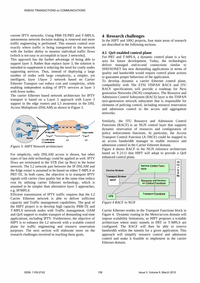
current IPTV networks. Using PBB-TE/PBT and T-MPLS, autonomous network decision making is removed and more traffic engineering is performed. This ensures control over exactly where traffic is being transported in the network with the further ability to monitor individual traffic flows (which is not easy to accomplish in layer 3 networks). This approach has the further advantage of being able to support layer 3. Rather than replace layer 3, the solution is intended to supplement it reducing the need for costly nodes supporting services. Thus, instead of deploying a large number of nodes with large complexity, a simpler, yet intelligent, layer 1/layer 2 network based on Carrier Ethernet Transport can reduce cost and complexity, while enabling independent scaling of IPTV services at layer 3 with fewer nodes. The carrier Ethernet based network architecture for IPTV transport is based on a Layer 2 approach with Layer 3 support in the edge routers and L3 awareness in the DSL Access Multiplexer (DSLAM) as shown in Figure 3.
Figure 3: HIPT Network architecture For simplicity, only DSLAM access is shown, but other types of last mile technology could be applied as well. IPTV flows are terminated in the STB (Set op Box) in the home network. The L2 network part between the IP DSLAM and the Edge router is assumed to be based on either T-MPLS or PBT-TE. In both cases, the objective is to transport IPTV signals with carrier class quality but at the same time reduce cost by utilising carrier Ethernet technology, which is assumed to be simpler than alternative layer 3 approaches, e.g. IP/MPLS. Efficient transmission of IPTV traffic requires that the L2 Carrier Ethernet network is able to deliver sufficient capacity and Traffic management capabilities. The goal of the HIPT project is to develop high capacity PBB-TE and T-MPLS network nodes with Traffic management, OAM and QoS support to enable transport of demanding real-time applications, including IPTV. Furthermore, the objective of HIPT is to enhance the L2 network with a scalable control plane for traffic engineering and resource reservation purposes. The next section will elaborate more on the research challenges involved in reaching these goals.
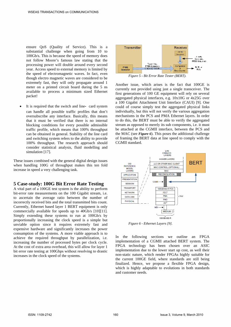
4 Research challenges In the HIPT and 100G projects, four main areas of research are described in the following sections. 4.1 QoS enabled control plane For PBT and T-MPLS, a dynamic control plane is a key area for future development. Today, the technologies deliver managed end-to-end connections similar to SHD/SONET but new demanding applications in terms of quality and bandwidth would require control plane actions to guarantee proper behaviour of the application. To develop dynamic a carrier Ethernet control plane, compatibility with The ETSI TISPAN RACS and ITU RACF specifications will provide a roadmap for Next generation Networks (NGN) compliance. The Resource and Admission Control Subsystem (RACS) layer is the TISPAN next-generation network subsystem that is responsible for elements of policing control, including resource reservation and admission control in the access and aggregation networks. Similarly, the ITU Resource and Admission Control Functions (RACF) is an NGN control layer that supports dynamic reservation of resources and configuration of policy enforcement functions. In particular, the Access Transport Control Function (A-TRCF) could be mapped to an access bandwidth manager to enable resource and admission control in the Carrier Ethernet domain. Figure 4 shows RACF in the NGN reference architecture based on Y.2111 that HIPT will adopt to provide a QoS enhanced control plane.
Figure 4 RACF in NGN Carrier Ethernet resides in the Transport Functions block in Figure 4. Dynamic routing in the Metro/access domain will impose scalability limitations, so HIPT proposes a scalable architecture where static tunnels in PBT or T-MPLS are configured. The RACF will then be able to reserve bandwidth within the tunnels for a given application. This approach will simplify resource control and admission control and make it feasible to implement in the carrier Ethernet domain.
WSEAS TRANSACTIONS on COMMUNICATIONSA. Rasmussen, J. Zhang, H. Yu, R. Fu, S. Ruepp, H. Wessing, M. Berger
ISSN: 1109-2742 158 Issue 3, Volume 9, March 2010

4.2 OAM for IPTV flow monitoring With the IPTV service, the viewers will directly watch the quality of the network, thus it is very important that the network delivers carrier grade quality. Today, the networks do not deliver the required OAM functionalities and IPTV operators are forced to deploy very expensive solutions to monitor the TV signals. Typically, monitoring the quality is done by decoding all the TV signals and showing them on screens on various locations in the network. Draft standard IEEE 802.1ag Connectivity Fault Management (CFM) has been recently developed to address the lack of end-to-end OAM in traditional Ethernet networks. It is closely aligned with the ITU's Y.1731 Recommendation (which also defines Performance Monitoring functions). Key functions such as loopback at specific MACs, linktrace to identify network paths and continuity check are defined. OAM is specific to the transport network and functionality is referenced from ITU-T's Y.1711 (OAM mechanism for MPLS networks). This provides the same OAM concepts and methods (e.g. connectivity verification, alarm suppression, remote defect indication) already available in other transport networks, without requiring complex IP data plane capabilities. Ongoing standardisation initiatives focus on G.8113 (Requirements for OAM functions in T-MPLS based networks) and G.8114 (Operation and maintenance mechanism for T-MPLS layer networks). In relation to OAM, the goal of HIPT is to be able to find a clear relation between user quality of experience and quantitative measurements in order to determine the threshold for sufficient network layer QoS. The vision is then to enable the Carrier Ethernet infrastructure to detect QoS degradations below the threshold by appropriate OAM mechanisms in the network layer. The level of IPTV awareness in the network layer OAM functions is a topic of research in HIPT. 4.3 Resiliency and survivability In PBB-TE, working and protection paths are precalculated, and the forwarding tables in nodes on these paths are provisioned/configured with the required forwarding entries. Both the working and protection traffic uses the MAC address of the destination node to fill the Destination MAC Address field. Working traffic uses the VID value assigned for the working path. A different VID value is used to forward the traffic along the protection path. Faults are detected and forwarded using a subset of 802.1ag connectivity fault management. Loss of Continuity Check is interpreted as a fault and also triggers protection switching. During path protection switching, the source nodes swap the VID value to redirect traffic onto the preconfigured protection path.
If span or local-bypass protection is used, VID tags are swapped at transit locations that bracket the failed span, node or sub-network connection. Switch-over times are short, because the required VID value and path are preconfigured. Survivability is specific to the transport network. T-MPLS therefore defines its protection capability using ITU-T's Recommendations G.8131/Y.1382 (T-MPLS linear protection switching with 1+1, 1:1 and 1:N options) and G.8132/Y.1383 (T-MPLS ring protection switching). MPLS Fast ReRoute (FRR) capability requires the use of LSP Merge that is excluded from T-MPLS. Network survivability traditionally deals with connection recovery after infrastructure or equipment failures, e.g. cable cuts or node outages, which are characterised by loss of signal [18]. In addition to these “hard failures”, users of IPTV may experience signal quality degradation as a “soft failure”, caused by gradual component degrading or malfunction. Since the customers’ perception of the signal quality is critical for the success of IP-TV, survivability measures related to “soft failures” will be investigated in HIPT.
4.4 Scaling to 100 Gigabit/s The main area of research in the 100G project is the challenges of scaling Ethernet capacity from current state‐ of‐ the‐ art at 10Gb/s to next generation 100Gb/s. The challenges will include interface adaptation, data and control plane processing, switching, power and printed circuit board requirements. The goal of 100Gb/s is very ambitious, and requires first of all improvements in the low level circuit technology. However, these improvements will be far from enough to deliver a factor 10 in performance when moving from 10Gb/s to 100Gb/s. The project will as a first step concentrate on a number of main research challenges that need to be addressed to reach a factor of 10 in performance:
• When a packet is received, several lookup operations will be performed to determine the appropriate treatment of the packet, i.e. destination, service level and profile conformance. Since Ethernet packets can be down to 512 bits (64 bytes) in size, this leaves us with only around 5 ns per packet for processing, which is extremely short time. Therefore, it is of utmost importance to develop a lookup algorithm, which is very fast and efficient in terms of memory utilisation.
• Access to external memory located next to the chips is necessary to perform traffic management and
WSEAS TRANSACTIONS on COMMUNICATIONSA. Rasmussen, J. Zhang, H. Yu, R. Fu, S. Ruepp, H. Wessing, M. Berger
ISSN: 1109-2742 159 Issue 3, Volume 9, March 2010
ensure QoS (Quality of Service). This is a substantial challenge when going from 10 to 100Gb/s. This is because the speed of memory does not follow Moore’s famous law stating that the processing power will double around every second year. Access speed to external memory is limited by the speed of electromagnetic waves. In fact, even though electro magnetic waves are considered to be extremely fast, they will only propagate around 1 meter on a printed circuit board during the 5 ns available to process a minimum sized Ethernet packet!
• It is required that the switch and line‐ card system can handle all possible traffic profiles that don’t oversubscribe any interface. Basically, this means that it must be verified that there is no internal blocking conditions for every possible admissible traffic profile, which means that 100% throughput can be obtained in general. Stability of the line card and switching system refers to the ability to provide 100% throughput. The research approach should consider statistical analysis, fluid modelling and simulation [17].
These issues combined with the general digital design issues when handling 100G of throughput makes this ten fold increase in speed a very challenging task. 5 Case-study: 100G Bit Error Rate Testing A vital part of a 100GE test system is the ability to perform bit-error rate measurements on the 100 Gigabit stream, i.e. to ascertain the average ratio between the number of incorrectly received bits and the total transmitted bits count. Currently, Ethernet based layer 1 BERT equipment is only commercially available for speeds up to 40Gb/s [10][11]. Simply extending these systems to run at 100Gb/s by proportionally increasing the clock speed is a simple but unviable option since it requires extremely fast and expensive hardware and significantly increases the power consumption of the systems. A more viable approach is to achieve the required throughput by parallelization, i.e. increasing the number of processed bytes per clock cycle. At the cost of extra area overhead, this will allow for layer 1 bit error rate testing at 100Gbps without resolving to drastic increases in the clock speed of the systems.
Figure 5 - Bit Error Rate Tester (BERT).
Another issue, which arises is the fact that 100GE is currently not provided using just a single transceiver. The first generations of 100 GE equipment will rely on several aggregated physical interfaces, e.g. 10x10G or 4x25G over a 100 Gigabit Attachment Unit Interface (CAUI) [9]. One could of course simply test the aggregated physical links individually, but this will not verify the various aggregation mechanisms in the PCS and PMA Ethernet layers. In order to do this, the BERT must be able to verify the aggregated stream as opposed to merely its sub components, i.e. it must be attached at the CGMII interface, between the PCS and the MAC (see Figure 6). This poses the additional challenge of framing the BERT data at line speed to comply with the CGMII standard.
Figure 6 - Ethernet Layers [9].
In the following sections we outline an FPGA implementation of a CGMII attached BERT system. The FPGA technology has been chosen over an ASIC implementation due to the lower start up cost, as well their non-static nature, which render FPGAs highly suitable for the current 100GE field, where standards are still being finalized. Hence, we propose a flexible FPGA design, which is highly adaptable to evolutions in both standards and customer needs.
WSEAS TRANSACTIONS on COMMUNICATIONSA. Rasmussen, J. Zhang, H. Yu, R. Fu, S. Ruepp, H. Wessing, M. Berger
ISSN: 1109-2742 160 Issue 3, Volume 9, March 2010
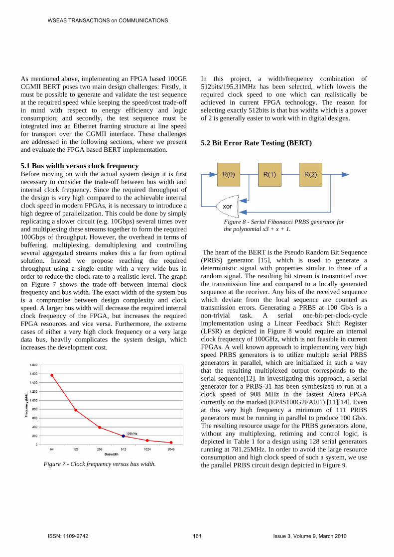
As mentioned above, implementing an FPGA based 100GE CGMII BERT poses two main design challenges: Firstly, it must be possible to generate and validate the test sequence at the required speed while keeping the speed/cost trade-off in mind with respect to energy efficiency and logic consumption; and secondly, the test sequence must be integrated into an Ethernet framing structure at line speed for transport over the CGMII interface. These challenges are addressed in the following sections, where we present and evaluate the FPGA based BERT implementation. 5.1 Bus width versus clock frequency Before moving on with the actual system design it is first necessary to consider the trade-off between bus width and internal clock frequency. Since the required throughput of the design is very high compared to the achievable internal clock speed in modern FPGAs, it is necessary to introduce a high degree of parallelization. This could be done by simply replicating a slower circuit (e.g. 10Gbps) several times over and multiplexing these streams together to form the required 100Gbps of throughput. However, the overhead in terms of buffering, multiplexing, demultiplexing and controlling several aggregated streams makes this a far from optimal solution. Instead we propose reaching the required throughput using a single entity with a very wide bus in order to reduce the clock rate to a realistic level. The graph on Figure 7 shows the trade-off between internal clock frequency and bus width. The exact width of the system bus is a compromise between design complexity and clock speed. A larger bus width will decrease the required internal clock frequency of the FPGA, but increases the required FPGA resources and vice versa. Furthermore, the extreme cases of either a very high clock frequency or a very large data bus, heavily complicates the system design, which increases the development cost.
Figure 7 - Clock frequency versus bus width.
In this project, a width/frequency combination of 512bits/195.31MHz has been selected, which lowers the required clock speed to one which can realistically be achieved in current FPGA technology. The reason for selecting exactly 512bits is that bus widths which is a power of 2 is generally easier to work with in digital designs.
5.2 Bit Error Rate Testing (BERT)
Figure 8 - Serial Fibonacci PRBS generator for the polynomial x3 + x + 1.
The heart of the BERT is the Pseudo Random Bit Sequence (PRBS) generator [15], which is used to generate a deterministic signal with properties similar to those of a random signal. The resulting bit stream is transmitted over the transmission line and compared to a locally generated sequence at the receiver. Any bits of the received sequence which deviate from the local sequence are counted as transmission errors. Generating a PRBS at 100 Gb/s is a non-trivial task. A serial one-bit-per-clock-cycle implementation using a Linear Feedback Shift Register (LFSR) as depicted in Figure 8 would require an internal clock frequency of 100GHz, which is not feasible in current FPGAs. A well known approach to implementing very high speed PRBS generators is to utilize multiple serial PRBS generators in parallel, which are initialized in such a way that the resulting multiplexed output corresponds to the serial sequence[12]. In investigating this approach, a serial generator for a PRBS-31 has been synthesized to run at a clock speed of 908 MHz in the fastest Altera FPGA currently on the marked (EP4S100G2FA0I1) [11][14]. Even at this very high frequency a minimum of 111 PRBS generators must be running in parallel to produce 100 Gb/s. The resulting resource usage for the PRBS generators alone, without any multiplexing, retiming and control logic, is depicted in Table 1 for a design using 128 serial generators running at 781.25MHz. In order to avoid the large resource consumption and high clock speed of such a system, we use the parallel PRBS circuit design depicted in Figure 9.
WSEAS TRANSACTIONS on COMMUNICATIONSA. Rasmussen, J. Zhang, H. Yu, R. Fu, S. Ruepp, H. Wessing, M. Berger
ISSN: 1109-2742 161 Issue 3, Volume 9, March 2010
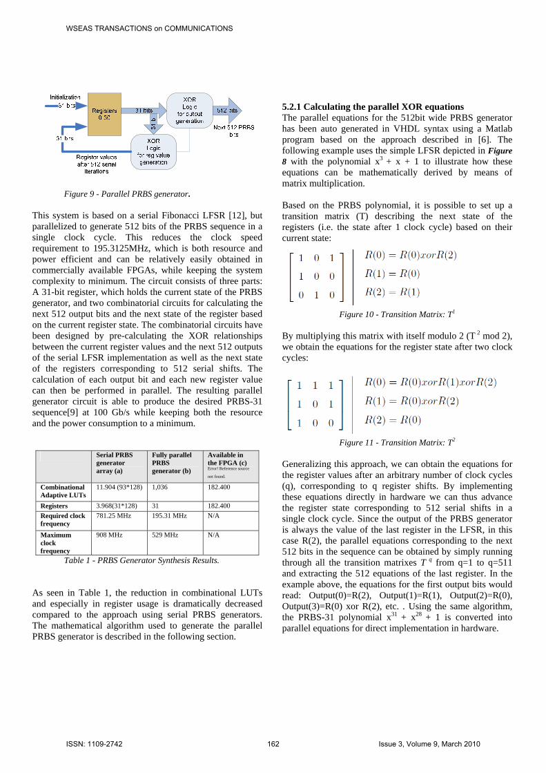
Figure 9 - Parallel PRBS generator.
This system is based on a serial Fibonacci LFSR [12], but parallelized to generate 512 bits of the PRBS sequence in a single clock cycle. This reduces the clock speed requirement to 195.3125MHz, which is both resource and power efficient and can be relatively easily obtained in commercially available FPGAs, while keeping the system complexity to minimum. The circuit consists of three parts: A 31-bit register, which holds the current state of the PRBS generator, and two combinatorial circuits for calculating the next 512 output bits and the next state of the register based on the current register state. The combinatorial circuits have been designed by pre-calculating the XOR relationships between the current register values and the next 512 outputs of the serial LFSR implementation as well as the next state of the registers corresponding to 512 serial shifts. The calculation of each output bit and each new register value can then be performed in parallel. The resulting parallel generator circuit is able to produce the desired PRBS-31 sequence[9] at 100 Gb/s while keeping both the resource and the power consumption to a minimum.
Serial PRBS generator array (a)
Fully parallel PRBS generator (b)
Available in the FPGA (c) Error! Reference source
not found. Combinational Adaptive LUTs
11.904 (93*128) 1,036 182.400
Registers 3.968(31*128) 31 182.400 Required clock frequency
781.25 MHz 195.31 MHz N/A
Maximum clock frequency
908 MHz 529 MHz N/A
Table 1 - PRBS Generator Synthesis Results. As seen in Table 1, the reduction in combinational LUTs and especially in register usage is dramatically decreased compared to the approach using serial PRBS generators. The mathematical algorithm used to generate the parallel PRBS generator is described in the following section.
5.2.1 Calculating the parallel XOR equations The parallel equations for the 512bit wide PRBS generator has been auto generated in VHDL syntax using a Matlab program based on the approach described in [6]. The following example uses the simple LFSR depicted in Figure 8 with the polynomial x3 + x + 1 to illustrate how these equations can be mathematically derived by means of matrix multiplication. Based on the PRBS polynomial, it is possible to set up a transition matrix (T) describing the next state of the registers (i.e. the state after 1 clock cycle) based on their current state:
Figure 10 - Transition Matrix: T1
By multiplying this matrix with itself modulo 2 (T 2 mod 2), we obtain the equations for the register state after two clock cycles:
Figure 11 - Transition Matrix: T2
Generalizing this approach, we can obtain the equations for the register values after an arbitrary number of clock cycles (q), corresponding to q register shifts. By implementing these equations directly in hardware we can thus advance the register state corresponding to 512 serial shifts in a single clock cycle. Since the output of the PRBS generator is always the value of the last register in the LFSR, in this case R(2), the parallel equations corresponding to the next 512 bits in the sequence can be obtained by simply running through all the transition matrixes T q from q=1 to q=511 and extracting the 512 equations of the last register. In the example above, the equations for the first output bits would read: Output(0)=R(2), Output(1)=R(1), Output(2)=R(0), Output(3)=R(0) xor R(2), etc. . Using the same algorithm, the PRBS-31 polynomial x31 + x28 + 1 is converted into parallel equations for direct implementation in hardware.
WSEAS TRANSACTIONS on COMMUNICATIONSA. Rasmussen, J. Zhang, H. Yu, R. Fu, S. Ruepp, H. Wessing, M. Berger
ISSN: 1109-2742 162 Issue 3, Volume 9, March 2010
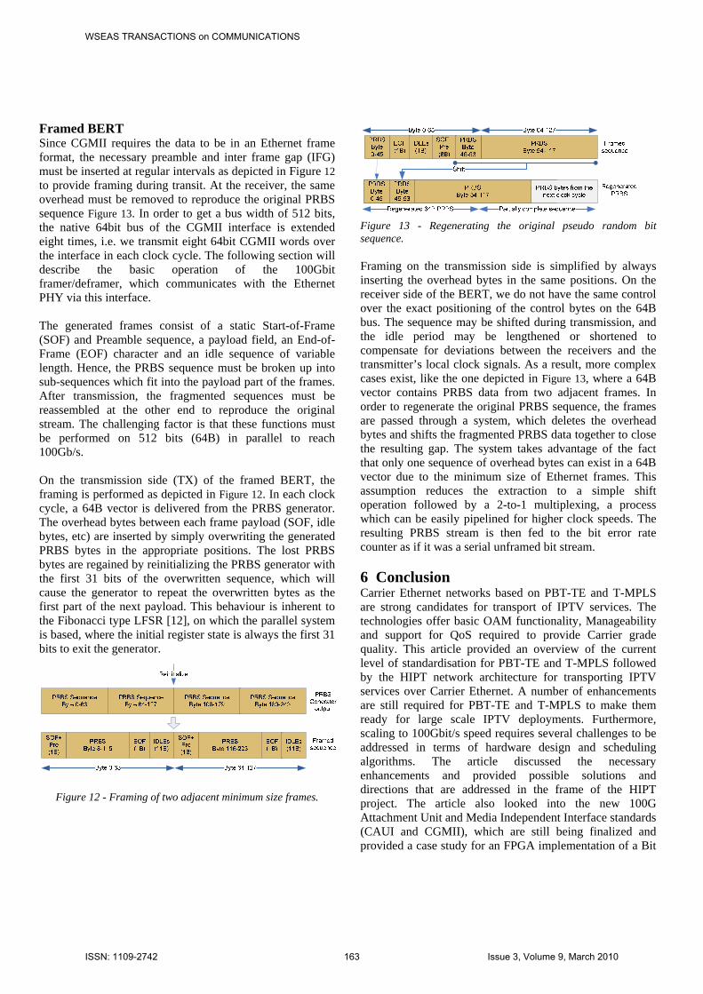
Framed BERT Since CGMII requires the data to be in an Ethernet frame format, the necessary preamble and inter frame gap (IFG) must be inserted at regular intervals as depicted in Figure 12 to provide framing during transit. At the receiver, the same overhead must be removed to reproduce the original PRBS sequence Figure 13. In order to get a bus width of 512 bits, the native 64bit bus of the CGMII interface is extended eight times, i.e. we transmit eight 64bit CGMII words over the interface in each clock cycle. The following section will describe the basic operation of the 100Gbit framer/deframer, which communicates with the Ethernet PHY via this interface. The generated frames consist of a static Start-of-Frame (SOF) and Preamble sequence, a payload field, an End-of-Frame (EOF) character and an idle sequence of variable length. Hence, the PRBS sequence must be broken up into sub-sequences which fit into the payload part of the frames. After transmission, the fragmented sequences must be reassembled at the other end to reproduce the original stream. The challenging factor is that these functions must be performed on 512 bits (64B) in parallel to reach 100Gb/s. On the transmission side (TX) of the framed BERT, the framing is performed as depicted in Figure 12. In each clock cycle, a 64B vector is delivered from the PRBS generator. The overhead bytes between each frame payload (SOF, idle bytes, etc) are inserted by simply overwriting the generated PRBS bytes in the appropriate positions. The lost PRBS bytes are regained by reinitializing the PRBS generator with the first 31 bits of the overwritten sequence, which will cause the generator to repeat the overwritten bytes as the first part of the next payload. This behaviour is inherent to the Fibonacci type LFSR [12], on which the parallel system is based, where the initial register state is always the first 31 bits to exit the generator.
Figure 12 - Framing of two adjacent minimum size frames.
Figure 13 - Regenerating the original pseudo random bit sequence. Framing on the transmission side is simplified by always inserting the overhead bytes in the same positions. On the receiver side of the BERT, we do not have the same control over the exact positioning of the control bytes on the 64B bus. The sequence may be shifted during transmission, and the idle period may be lengthened or shortened to compensate for deviations between the receivers and the transmitter’s local clock signals. As a result, more complex cases exist, like the one depicted in Figure 13, where a 64B vector contains PRBS data from two adjacent frames. In order to regenerate the original PRBS sequence, the frames are passed through a system, which deletes the overhead bytes and shifts the fragmented PRBS data together to close the resulting gap. The system takes advantage of the fact that only one sequence of overhead bytes can exist in a 64B vector due to the minimum size of Ethernet frames. This assumption reduces the extraction to a simple shift operation followed by a 2-to-1 multiplexing, a process which can be easily pipelined for higher clock speeds. The resulting PRBS stream is then fed to the bit error rate counter as if it was a serial unframed bit stream. 6 Conclusion Carrier Ethernet networks based on PBT-TE and T-MPLS are strong candidates for transport of IPTV services. The technologies offer basic OAM functionality, Manageability and support for QoS required to provide Carrier grade quality. This article provided an overview of the current level of standardisation for PBT-TE and T-MPLS followed by the HIPT network architecture for transporting IPTV services over Carrier Ethernet. A number of enhancements are still required for PBT-TE and T-MPLS to make them ready for large scale IPTV deployments. Furthermore, scaling to 100Gbit/s speed requires several challenges to be addressed in terms of hardware design and scheduling algorithms. The article discussed the necessary enhancements and provided possible solutions and directions that are addressed in the frame of the HIPT project. The article also looked into the new 100G Attachment Unit and Media Independent Interface standards (CAUI and CGMII), which are still being finalized and provided a case study for an FPGA implementation of a Bit
WSEAS TRANSACTIONS on COMMUNICATIONSA. Rasmussen, J. Zhang, H. Yu, R. Fu, S. Ruepp, H. Wessing, M. Berger
ISSN: 1109-2742 163 Issue 3, Volume 9, March 2010

Error Rate Tester (BERT) for the new CGMII interface. Our results show that it is indeed possible to implement such a tester on a modern FPGA platform with modest resource usage, thus leaving plenty of space for additional functionality on the chip. References: [1] IEEE Std. 802.1Q-2005: Virtual Bridged Local
Area Networks. [2] IEEE Std. 802.1ad-2005: Virtual Bridged Local
Area Networks. Amendment 4: Provider Bridges. [3] IEEE Draft 802.1ah: Provider Backbone Bridges. [4] IEEE Std. 802.3ah-2004: Ethernet in the First Mile. [5] IEEE Draft 802.1ag: Connectivity Fault Manage-
ment. [6] ITU-T G.805-2000: Generic functional architecture
of transport networks. [7] ITU-T G.809-2003: Functional architecture of
connectionless layer networks. [8] M. Rowe, “40-Gbps and 100-Gbps Ethernet will
bring new test challenges,” Test & Measurement World, Mar. 2009.
[9] LAN/MAN Standards Committee of the IEEE Computer Society, “IEEE p802.3ba d2.1 - amendment: Media access control parameters, physical layers and management parameters for 40 gb/s and 100 gb/s operation,” pp. 144–156, 2009.
[10] EXFO, “EXFO product listing: www.exfo.com,” Jan. 2010.
[11] Altera Corporation, “Altera product listing: www.altera.com,” IEEE JOURNAL OF SOLID-STATE CIRCUITS, Jan. 2010.
[12] H. Veenstra and J.R. Long, “Circuit and inter-connect design for rf and high bit-rate applications,” 2008.
[13] E. Laskin and S. P. Voinigescu, “A 60 mw per lane, 4x23-gb/s 2(7)-1 prbs generator,” IEEE JOURNAL OF SOLID-STATE CIRCUITS, vol. 41, no. 10, pp. 2198–2208, Oct. 2006.
[14] Altera Corporation, “Stratix IV device handbook,” p. 15, 2009.
[15] N.G Bardis, A.P. Markovskyy and D.V. Andrikou , “Method for designing pseudorandom binary sequences generators on nonlinear feedback shift register (NFSR)”, WSEAS Transactions on Communications, vol. 3, Issue 2, pp.758-763, 2004.
[16] R. Bruzgiene, L. Narbutaite, T. Adomkus, “Analysis of quality parameters influence to translation of IPTV service”, WSEAS Transactions on Communications, vol. 4, Issue 11, pp.551-560, 2009.
[17] J. Incera, L. Carballo, “A fluid model of the RED AQM algorithm and its implementation in a fluid-based network simulator”, WSEAS Transactions on Communications, vol. 5, Issue 6, pp.1081-1096, 2006.
[18] S. Ruepp, T. Stidsen, L. Dittmann, M. Berger, “Capacity Efficiency of Recovery Request Bundling”, WSEAS International conference: Recent Advances in Curcuits, Systems, Signal and Telecommunications; Jan. 2010.
WSEAS TRANSACTIONS on COMMUNICATIONSA. Rasmussen, J. Zhang, H. Yu, R. Fu, S. Ruepp, H. Wessing, M. Berger
ISSN: 1109-2742 164 Issue 3, Volume 9, March 2010