Tools for simulation and visualization of complex - Departamento de
8
Proceedings of Virtual Concept 2005 Biarritz, France, November 8 th – November 10 th , 2005 Tools for simulation and visualization of complex illumination environments Emilio J. Sobreviela, Francisco J. Seron, Sandra Baldassarri, Juan A. Magallon, Diego Gutierrez Grupo de Informática Gráfica Avanzada Informática e Ingeniería de Sistemas – Centro Politécnico Superior University of Zaragoza C/ María de Luna, 1 50018-Zaragoza (Spain) Phone: +34 976762355 / Fax: +34 976761914 E-mail : {emilioj,seron,sandra,magallon,diegog}@unizar.es Abstract: The aim of this paper is to present the tools and methods developed for the visualization and simulation of industrial complex illumination projects, such as the ergonomics and usability of space inside buildings or the analysis of vial security scenarios. In such cases, not only realistic illumination but also moving objects or persons are key for human perception. The developed tools consist of two software packages for calculating lighting simulation, a package for the simulation of the human visual system and another package for the animation of human locomotion. All these software are integrated in our Cave-Like System. The simulations done with our hardware and software include the physical phenomena that happen when light and matter interact in complex environments where there are moving elements, amongst which virtual humans stand out. In this way, the results presented in the immersive environment are as close to reality as possible, as perceived by a human observer. Key words: CAVE; Stereoscopy; Lighting Design; Perception; Virtual Humans. 1- Introduction The gap between lighting design and computer graphics has been filled in recent years, when computer graphics algorithms have been used to solve complex lighting simulations. This implies a conversion of the algorithms to full simulation systems, where physical data are used to drive the simulation. The results then become numbers, not images. Visualization of these data is very important in this kind of simulations. Many techniques derived from Numeric Data Visualization can be applied to analyze data from an engineering point of view. But also a realistic visualization for scene imagery is needed, and therefore a full new field of research appears: the understanding and simulation of the Human Visualization System (HVS), to try to match the impressions the observer would feel when looking at the real scene. However, depending on the final application, the precise simulation of the light is not enough. Virtual humans are necessary in order to achieve a natural feel in the scene, more credible environments and a greater sensation of reality, or are even essential elements when studying certain problems in areas such as road lighting. Of course new methods of interaction with those visualizations are also needed. For real collaborative work, immersive systems offer new interesting possibilities, and they should also allow some kind of interactive control by the user. New technologies can be used to lower the cost of such systems. The remainder of this paper develops as follows: Section 2 presents a general description of the hardware and software that conforms the immersive visualization system, a new Cave-Like System as evolution of the previously one, exposed in Virtual Concept 2002[1]. Section 3 explains, in detail, the software packages developed for lighting simulation (ALEPH, SICARA3D and SEKER). In Section 4 there is a description of the developed human locomotion system, named BILL. In Section 5 several case studies with virtual humans walking in different environments are presented. Here, the results obtained with the developed software are reflected. Finally, in Section 6, the conclusions and the possible future works are exposed. 2- Visualization system The architects and lighting engineers demand more and more capacity to see their lighting designs in a way that closer mimics reality. For that reason we have also added the power of low-cost, PC-based CAVE immersive systems. With this combination, we include stereoscopy [2] and a collaborative environment to the reliability of the numerical results and the realistic aspect of the imagery. Several users can now see and feel how a given lighting project is going to work out, even 62 -1- Copyright Virtual Concept
Transcript of Tools for simulation and visualization of complex - Departamento de
Proceedings of Virtual Concept 2005 Biarritz, France, November 8th – November 10th, 2005
Tools for simulation and visualization of complex illumination environments
Emilio J. Sobreviela, Francisco J. Seron, Sandra Baldassarri, Juan A. Magallon, Diego Gutierrez
Grupo de Informática Gráfica Avanzada Informática e Ingeniería de Sistemas – Centro Politécnico Superior
University of Zaragoza C/ María de Luna, 1 50018-Zaragoza (Spain) Phone: +34 976762355 / Fax: +34 976761914
E-mail : {emilioj,seron,sandra,magallon,diegog}@unizar.es
Abstract: The aim of this paper is to present the tools and methods developed for the visualization and simulation of industrial complex illumination projects, such as the ergonomics and usability of space inside buildings or the analysis of vial security scenarios. In such cases, not only realistic illumination but also moving objects or persons are key for human perception.
The developed tools consist of two software packages for calculating lighting simulation, a package for the simulation of the human visual system and another package for the animation of human locomotion. All these software are integrated in our Cave-Like System.
The simulations done with our hardware and software include the physical phenomena that happen when light and matter interact in complex environments where there are moving elements, amongst which virtual humans stand out. In this way, the results presented in the immersive environment are as close to reality as possible, as perceived by a human observer.
Key words: CAVE; Stereoscopy; Lighting Design; Perception; Virtual Humans.
1- Introduction
The gap between lighting design and computer graphics has been filled in recent years, when computer graphics algorithms have been used to solve complex lighting simulations. This implies a conversion of the algorithms to full simulation systems, where physical data are used to drive the simulation. The results then become numbers, not images. Visualization of these data is very important in this kind of simulations. Many techniques derived from Numeric Data Visualization can be applied to analyze data from an engineering point of view. But also a realistic visualization for scene imagery is needed, and therefore a full new field of research appears: the understanding and simulation of the Human Visualization System (HVS), to try to match the impressions the observer would feel when looking at the real scene.
However, depending on the final application, the precise simulation of the light is not enough. Virtual humans are necessary in order to achieve a natural feel in the scene, more credible environments and a greater sensation of reality, or are even essential elements when studying certain problems in areas such as road lighting.
Of course new methods of interaction with those visualizations are also needed. For real collaborative work, immersive systems offer new interesting possibilities, and they should also allow some kind of interactive control by the user. New technologies can be used to lower the cost of such systems.
The remainder of this paper develops as follows: Section 2 presents a general description of the hardware and software that conforms the immersive visualization system, a new Cave-Like System as evolution of the previously one, exposed in Virtual Concept 2002[1]. Section 3 explains, in detail, the software packages developed for lighting simulation (ALEPH, SICARA3D and SEKER). In Section 4 there is a description of the developed human locomotion system, named BILL. In Section 5 several case studies with virtual humans walking in different environments are presented. Here, the results obtained with the developed software are reflected. Finally, in Section 6, the conclusions and the possible future works are exposed.
2- Visualization system
The architects and lighting engineers demand more and more capacity to see their lighting designs in a way that closer mimics reality. For that reason we have also added the power of low-cost, PC-based CAVE immersive systems. With this combination, we include stereoscopy [2] and a collaborative environment to the reliability of the numerical results and the realistic aspect of the imagery. Several users can now see and feel how a given lighting project is going to work out, even
62 -1- Copyright Virtual Concept
Virtual Concept 2005 Tools for simulation and visualization
from its early design stages.
Since our system visualization is an alternative approach to the classical CAVE [3] we have named it CAVE-Like System [4] or, more commonly, CLS.
Four to eight people can fit in comfortably, although there is only one ideal point of view from which perspective and stereoscopy appear to be perfect, since it is the point of view for which both have been calculated.
The CLS works under two different modes of visualization: when the design implies a complex simulation of light and matter, and the results also depend on the point of view in the scene, the low-cost approach rules out the notion of real time. The images and animations are therefore prerendered, and the interaction with the audience is limited to selecting a given image or animation. When the results do not depend on the point of view, the transfer of energy in the scene is calculated only once, and the audience can then interact with the synthetic world by using wireless mice or joysticks.
2.1 – Hardware
The idea of the CLS is that imagery projected on each screen is generated by separate PCs, which are synchronized by another computer. Although we use consumer class PCs (commonly used for gaming) performance is fair enough for our purpose.
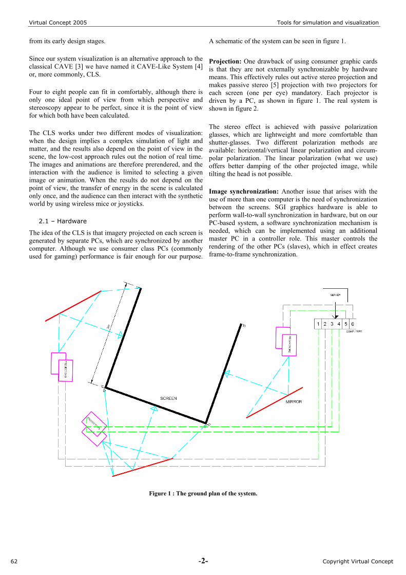
A schematic of the system can be seen in figure 1.
Projection: One drawback of using consumer graphic cards is that they are not externally synchronizable by hardware means. This effectively rules out active stereo projection and makes passive stereo [5] projection with two projectors for each screen (one per eye) mandatory. Each projector is driven by a PC, as shown in figure 1. The real system is shown in figure 2.
The stereo effect is achieved with passive polarization glasses, which are lightweight and more comfortable than shutter-glasses. Two different polarization methods are available: horizontal/vertical linear polarization and circum-polar polarization. The linear polarization (what we use) offers better damping of the other projected image, while tilting the head is not possible.
Image synchronization: Another issue that arises with the use of more than one computer is the need of synchronization between the screens. SGI graphics hardware is able to perform wall-to-wall synchronization in hardware, but on our PC-based system, a software synchronization mechanism is needed, which can be implemented using an additional master PC in a controller role. This master controls the rendering of the other PCs (slaves), which in effect creates frame-to-frame synchronization.
Figure 1 : The ground plan of the system.
62 -2- Copyright Virtual Concept
Virtual Concept 2005 Tools for simulation and visualization
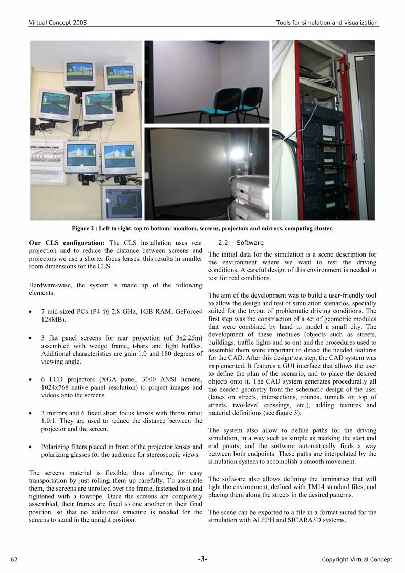
Figure 2 : Left to right, top to bottom: monitors, screens, projectors and mirrors, computing cluster.
Our CLS configuration: The CLS installation uses rear projection and to reduce the distance between screens and projectors we use a shorter focus lenses; this results in smaller room dimensions for the CLS.
Hardware-wise, the system is made up of the following elements:
• 7 mid-sized PCs (P4 @ 2,8 GHz, 1GB RAM, GeForce4 128MB).
• 3 flat panel screens for rear projection (of 3x2.25m) assembled with wedge frame, t-bars and light baffles. Additional characteristics are gain 1.0 and 180 degrees of viewing angle.
• 6 LCD projectors (XGA panel, 3000 ANSI lumens, 1024x768 native panel resolution) to project images and videos onto the screens.
• 3 mirrors and 6 fixed short focus lenses with throw ratio: 1.0:1. They are used to reduce the distance between the projector and the screen.
• Polarizing filters placed in front of the projector lenses and polarizing glasses for the audience for stereoscopic views.
The screens material is flexible, thus allowing for easy transportation by just rolling them up carefully. To assemble them, the screens are unrolled over the frame, fastened to it and tightened with a towrope. Once the screens are completely assembled, their frames are fixed to one another in their final position, so that no additional structure is needed for the screens to stand in the upright position.
2.2 – Software
The initial data for the simulation is a scene description for the environment where we want to test the driving conditions. A careful design of this environment is needed to test for real conditions.
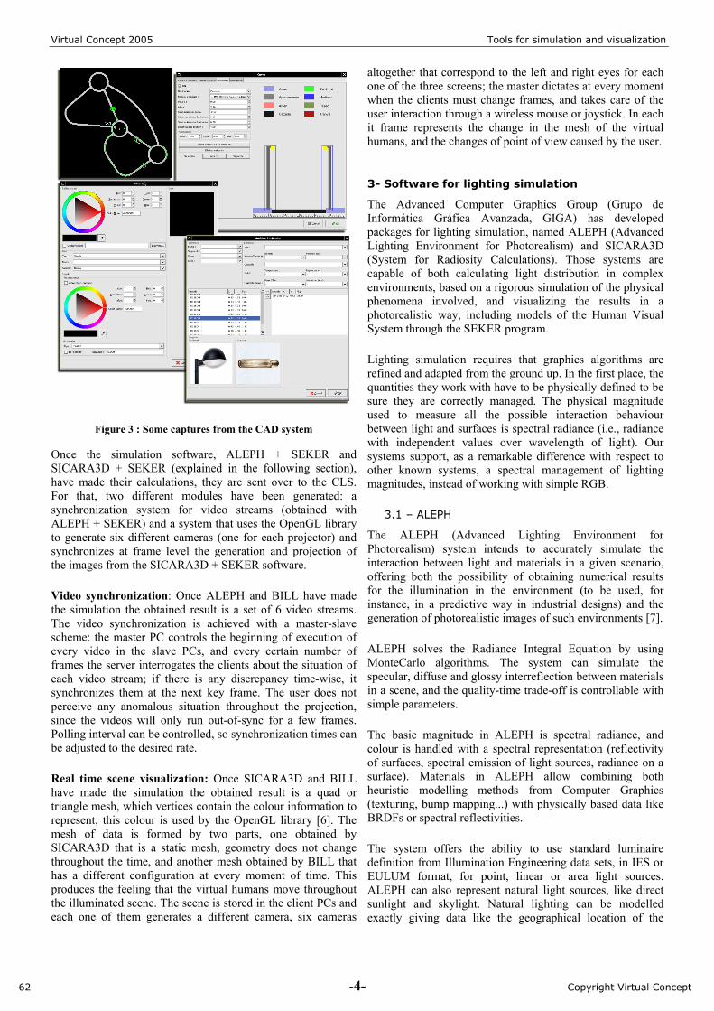
The aim of the development was to build a user-friendly tool to allow the design and test of simulation scenarios, specially suited for the tryout of problematic driving conditions. The first step was the construction of a set of geometric modules that were combined by hand to model a small city. The development of these modules (objects such as streets, buildings, traffic lights and so on) and the procedures used to assemble them were important to detect the needed features for the CAD. After this design/test step, the CAD system was implemented. It features a GUI interface that allows the user to define the plan of the scenario, and to place the desired objects onto it. The CAD system generates procedurally all the needed geometry from the schematic design of the user (lanes on streets, intersections, rounds, tunnels on top of streets, two-level crossings, etc.), adding textures and material definitions (see figure 3).
The system also allow to define paths for the driving simulation, in a way such as simple as marking the start and end points, and the software automatically finds a way between both endpoints. These paths are interpolated by the simulation system to accomplish a smooth movement.
The software also allows defining the luminaries that will light the environment, defined with TM14 standard files, and placing them along the streets in the desired patterns.
The scene can be exported to a file in a format suited for the simulation with ALEPH and SICARA3D systems.
62 -3- Copyright Virtual Concept
Virtual Concept 2005 Tools for simulation and visualization
Figure 3 : Some captures from the CAD system
Once the simulation software, ALEPH + SEKER and SICARA3D + SEKER (explained in the following section), have made their calculations, they are sent over to the CLS. For that, two different modules have been generated: a synchronization system for video streams (obtained with ALEPH + SEKER) and a system that uses the OpenGL library to generate six different cameras (one for each projector) and synchronizes at frame level the generation and projection of the images from the SICARA3D + SEKER software.
Video synchronization: Once ALEPH and BILL have made the simulation the obtained result is a set of 6 video streams. The video synchronization is achieved with a master-slave scheme: the master PC controls the beginning of execution of every video in the slave PCs, and every certain number of frames the server interrogates the clients about the situation of each video stream; if there is any discrepancy time-wise, it synchronizes them at the next key frame. The user does not perceive any anomalous situation throughout the projection, since the videos will only run out-of-sync for a few frames. Polling interval can be controlled, so synchronization times can be adjusted to the desired rate.
Real time scene visualization: Once SICARA3D and BILL have made the simulation the obtained result is a quad or triangle mesh, which vertices contain the colour information to represent; this colour is used by the OpenGL library [6]. The mesh of data is formed by two parts, one obtained by SICARA3D that is a static mesh, geometry does not change throughout the time, and another mesh obtained by BILL that has a different configuration at every moment of time. This produces the feeling that the virtual humans move throughout the illuminated scene. The scene is stored in the client PCs and each one of them generates a different camera, six cameras
altogether that correspond to the left and right eyes for each one of the three screens; the master dictates at every moment when the clients must change frames, and takes care of the user interaction through a wireless mouse or joystick. In each it frame represents the change in the mesh of the virtual humans, and the changes of point of view caused by the user.
3- Software for lighting simulation
The Advanced Computer Graphics Group (Grupo de Informática Gráfica Avanzada, GIGA) has developed packages for lighting simulation, named ALEPH (Advanced Lighting Environment for Photorealism) and SICARA3D (System for Radiosity Calculations). Those systems are capable of both calculating light distribution in complex environments, based on a rigorous simulation of the physical phenomena involved, and visualizing the results in a photorealistic way, including models of the Human Visual System through the SEKER program.
Lighting simulation requires that graphics algorithms are refined and adapted from the ground up. In the first place, the quantities they work with have to be physically defined to be sure they are correctly managed. The physical magnitude used to measure all the possible interaction behaviour between light and surfaces is spectral radiance (i.e., radiance with independent values over wavelength of light). Our systems support, as a remarkable difference with respect to other known systems, a spectral management of lighting magnitudes, instead of working with simple RGB.
3.1 – ALEPH
The ALEPH (Advanced Lighting Environment for Photorealism) system intends to accurately simulate the interaction between light and materials in a given scenario, offering both the possibility of obtaining numerical results for the illumination in the environment (to be used, for instance, in a predictive way in industrial designs) and the generation of photorealistic images of such environments [7].
ALEPH solves the Radiance Integral Equation by using MonteCarlo algorithms. The system can simulate the specular, diffuse and glossy interreflection between materials in a scene, and the quality-time trade-off is controllable with simple parameters.
The basic magnitude in ALEPH is spectral radiance, and colour is handled with a spectral representation (reflectivity of surfaces, spectral emission of light sources, radiance on a surface). Materials in ALEPH allow combining both heuristic modelling methods from Computer Graphics (texturing, bump mapping...) with physically based data like BRDFs or spectral reflectivities.
The system offers the ability to use standard luminaire definition from Illumination Engineering data sets, in IES or EULUM format, for point, linear or area light sources. ALEPH can also represent natural light sources, like direct sunlight and skylight. Natural lighting can be modelled exactly giving data like the geographical location of the
62 -4- Copyright Virtual Concept
Virtual Concept 2005 Tools for simulation and visualization
scene (latitude-longitude), date and time of day, and clearness or turbidity of the sky.
Results from ALEPH are spectral radiance values computed over a finite mesh on top of surfaces of the scene (to produce a view-independent solution), or spectral radiance images (view-dependent solutions), where full complex materials can be managed correctly.
3.2 – SICARA3D
SICARA3D (System for Radiosity Calculations) is based on progressive radiosity [8]. SICARA3D quantifies the intensity of light at any point in a scene, in real units (luxes, candles) and generates images that look realistic. This software solves the light distribution with the radiosity global illumination methods [9].
SICARA3D is built by three differentiated modules: a CAD module for the description of the scene; a simulator of the light/matter interaction and a 3D visualizer of the results of the simulation. In the first part of the calculations SICARA3D uses ray tracing techniques and spatial indexing methods, to reduce computation times for ray-scene intersections. After that, SICARA3D works with progressive radiosity to solve the linear system of equations. Finally, as an extra option, SICARA3D can generate an image using the results of the radiosity calculation plus a simple ray tracer, so that surfaces with reflections can be obtained. The CAD tool allows describing the geometry of the scene with parametric surfaces or importing 3DS files, the properties of the materials, as well as the definition of the light sources. We have integrated a vegetation generator module for exteriors scenes that allows defining trees and shrubs in their different growth stages.
The light sources that can be defined are: an extensive light source, it consists of an object with one or more surfaces with emission properties; a luminary with real photometric data in Indal, Eulumdat and TM14 format (depending on the luminary manufacturer); and the solar illumination, calculated by giving the location (through latitude and longitude or through the name of a city), the date, the hour and indicating if the sky is clear or cloudy.
The results obtained by SICARA3D are view-independent, which allows representing the values obtained over the mesh of the surfaces with the OpenGL graphics library.
3.3 – SEKER
Named after an Egyptian god of light, SEKER has also been developed by GIGA. It is a software suite that correctly maps world luminances to display luminances, while including a model of the Human Visual System (HVS). The algorithms are based on the notion that we perceive our world by the sensation of brightness (which is based on contrast), not by absolute luminances themselves. The HSV model takes into account several effects such as veiling glare, colour loss, loss of visual acuity or bleaching of the photoreceptors. This software can post process the images generated by either ALEPH or SICARA3D, in order to generate an image that
provokes the same physiological responses as when viewing the real scene in the real world.
4- Software for human animation
The process of animating realistic human locomotion involves two aims: the description of the body shape and the generation of the body movement. Although our calculation system is based on a skeleton model, the final graphical output allows the representation of the human body as a skeleton, a wireframe model or a surface model.
Concerning with the development of human locomotion algorithms, two main approaches are commonly adopted in Computer Graphics: methods built on knowledge-based kinematics and methods that use dynamics or that incorporate dynamic constraints in the generation of motion. For getting the benefices of the realism offered by dynamics laws without having to specify the forces that create the motion, our system uses a hybrid kinematic-dynamic method [10][11][12].
4.1 – System Description
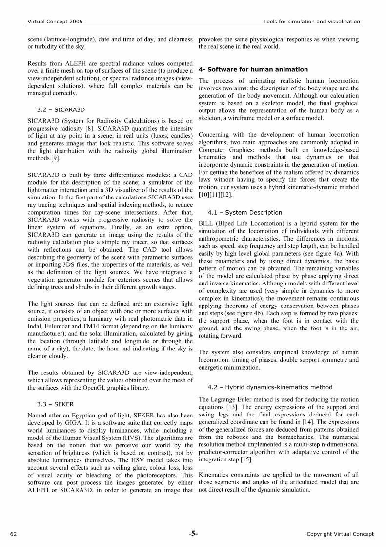
BILL (BIped Life Locomotion) is a hybrid system for the simulation of the locomotion of individuals with different anthropometric characteristics. The differences in motions, such as speed, step frequency and step length, can be handled easily by high level global parameters (see figure 4a). With these parameters and by using direct dynamics, the basic pattern of motion can be obtained. The remaining variables of the model are calculated phase by phase applying direct and inverse kinematics. Although models with different level of complexity are used (very simple in dynamics to more complex in kinematics); the movement remains continuous applying theorems of energy conservation between phases and steps (see figure 4b). Each step is formed by two phases: the support phase, when the foot is in contact with the ground, and the swing phase, when the foot is in the air, rotating forward.
The system also considers empirical knowledge of human locomotion: timing of phases, double support symmetry and energetic minimization.
4.2 – Hybrid dynamics-kinematics method
The Lagrange-Euler method is used for deducing the motion equations [13]. The energy expressions of the support and swing legs and the final expressions deduced for each generalized coordinate can be found in [14]. The expressions of the generalized forces are deduced from patterns obtained from the robotics and the biomechanics. The numerical resolution method implemented is a multi-step n-dimensional predictor-corrector algorithm with adaptative control of the integration step [15].
Kinematics constraints are applied to the movement of all those segments and angles of the articulated model that are not direct result of the dynamic simulation.
62 -5- Copyright Virtual Concept
Virtual Concept 2005 Tools for simulation and visualization
(a) Levels of control (b) Finite State Machine for the calculation of each step
Figure 4 : Human Locomotion System
The constraints can fit to values extracted from anthropometrical measures, either experimental or aesthetic, that allow the characterization of each animation individually. The kinematics of the support leg reflects the biomechanical performance of the knee and the ankle while the kinematics of the swing leg completes the foot movement by linear interpolation. The upper body model kinematically simulates all the vertebral column gathering the movements according to lumbar, thoracic and cervical vertebras. In the transverse plane, the shoulders rotate in an opposite direction and proportionally to the pelvis. In the walking plane, instead, the arms rotate proportionally to the “dynamic” angle of the hip of the opposite leg and the forearms are directly interpolated between the experimental values.
4.3 – Output
The locomotion system allows obtaining different graphical outputs of humans with different anthropometric characteristics. These outputs are: a final real time visualization with the human body as a skeleton, either a wireframe model or surface model; a VRML file with the information about the geometry and the movements of the body; files with the GL coordinates, one for each time step; and still images or video sequences.
5- Case studies
In this section we present some of the results obtained in the Light Simulation Lab combining all the packages previously described within the CLS environment. Also the results of including the virtual humans in a commercial software are presented.
5.1 – Working with PERFORMER
Driving simulators try to create a sensation of being there for the drivers. Including moving human characters help to increase the feeling of immersion in the environment. The simplest lighting scenario consists on working with a no-realistic scene, generating images that look like those from a video game. In this sense we have chosen to work with the PERFORMER commercial library, owed to its versatility and multi-platform availability.
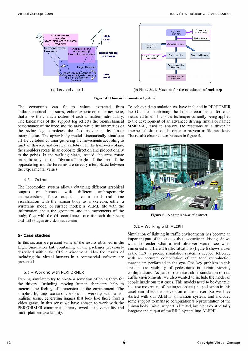
To achieve the simulation we have included in PERFOMER the GL files containing the human coordinates for each measured time. This is the technique currently being applied to the development of an advanced driving simulator named SIMPRAC, used to analyze the reactions of a driver in unexpected situations, in order to prevent traffic accidents. The results obtained can be seen in figure 5.
Figure 5 : A sample view of a street
5.2 – Working with ALEPH
Simulation of lighting in traffic environments has become an important part of the studies about security in driving. As we want to render what a real observer would see when immersed in different traffic situations (figure 6 shows a user in the CLS), a precise simulation system is needed, followed with an accurate computation of the tone reproduction mechanism performed in the eye. One key problem in this area is the visibility of pedestrians in certain viewing configurations. As part of our research in simulation of real traffic environments, we also wanted to include the model of people inside our test cases. This models need to be dynamic, because movement of the target object (the pedestrian in this case) can affect the perception of the driver. So we have started with our ALEPH simulation system, and included some support to manage computational representation of the human body. Initial support is limited, but plans exist to fully integrate the output of the BILL system into ALEPH.
62 -6- Copyright Virtual Concept
Virtual Concept 2005 Tools for simulation and visualization
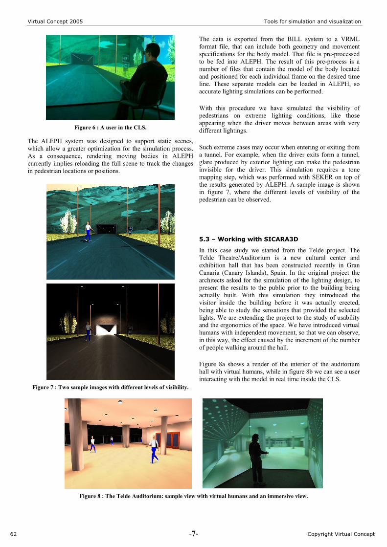
Figure 6 : A user in the CLS.
The ALEPH system was designed to support static scenes, which allow a greater optimization for the simulation process. As a consequence, rendering moving bodies in ALEPH currently implies reloading the full scene to track the changes in pedestrian locations or positions.
Figure 7 : Two sample images with different levels of visibility.
The data is exported from the BILL system to a VRML format file, that can include both geometry and movement specifications for the body model. That file is pre-processed to be fed into ALEPH. The result of this pre-process is a number of files that contain the model of the body located and positioned for each individual frame on the desired time line. These separate models can be loaded in ALEPH, so accurate lighting simulations can be performed.
With this procedure we have simulated the visibility of pedestrians on extreme lighting conditions, like those appearing when the driver moves between areas with very different lightings.
Such extreme cases may occur when entering or exiting from a tunnel. For example, when the driver exits form a tunnel, glare produced by exterior lighting can make the pedestrian invisible for the driver. This simulation requires a tone mapping step, which was performed with SEKER on top of the results generated by ALEPH. A sample image is shown in figure 7, where the different levels of visibility of the pedestrian can be observed.
5.3 – Working with SICARA3D
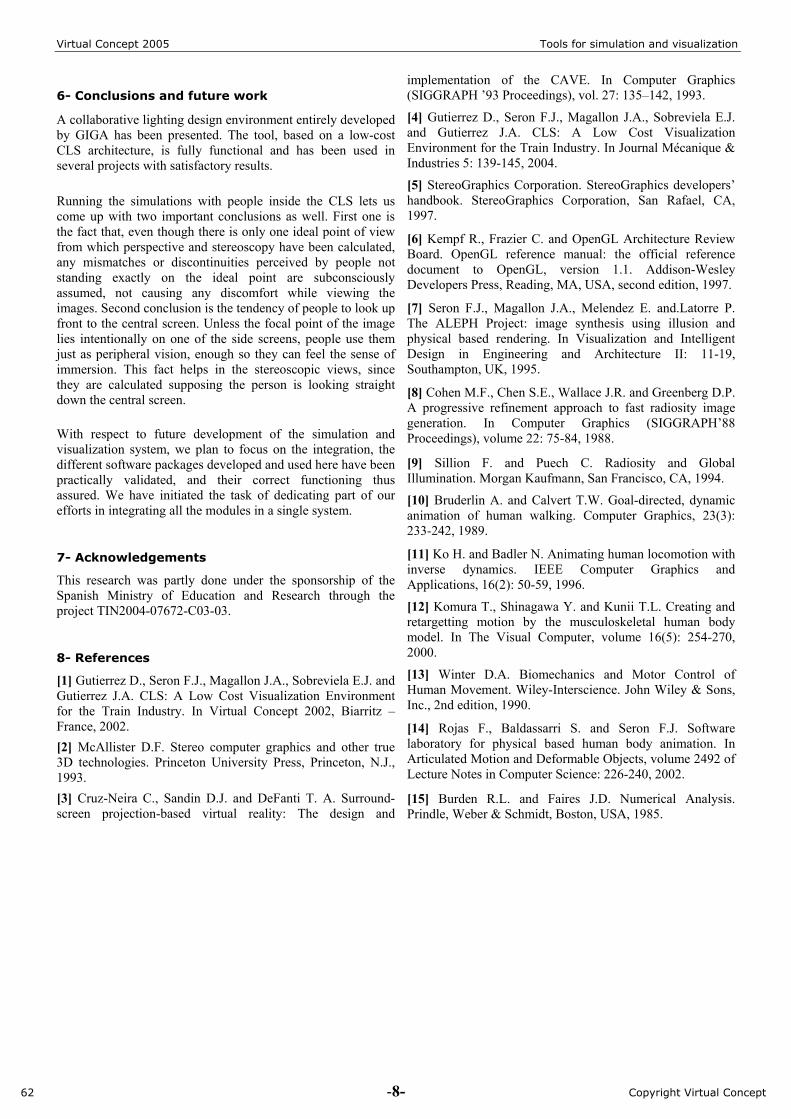
In this case study we started from the Telde project. The Telde Theatre/Auditorium is a new cultural center and exhibition hall that has been constructed recently in Gran Canaria (Canary Islands), Spain. In the original project the architects asked for the simulation of the lighting design, to present the results to the public prior to the building being actually built. With this simulation they introduced the visitor inside the building before it was actually erected, being able to study the sensations that provided the selected lights. We are extending the project to the study of usability and the ergonomics of the space. We have introduced virtual humans with independent movement, so that we can observe, in this way, the effect caused by the increment of the number of people walking around the hall.
Figure 8a shows a render of the interior of the auditorium hall with virtual humans, while in figure 8b we can see a user interacting with the model in real time inside the CLS.
Figure 8 : The Telde Auditorium: sample view with virtual humans and an immersive view.
62 -7- Copyright Virtual Concept
Virtual Concept 2005 Tools for simulation and visualization
6- Conclusions and future work
A collaborative lighting design environment entirely developed by GIGA has been presented. The tool, based on a low-cost CLS architecture, is fully functional and has been used in several projects with satisfactory results.
Running the simulations with people inside the CLS lets us come up with two important conclusions as well. First one is the fact that, even though there is only one ideal point of view from which perspective and stereoscopy have been calculated, any mismatches or discontinuities perceived by people not standing exactly on the ideal point are subconsciously assumed, not causing any discomfort while viewing the images. Second conclusion is the tendency of people to look up front to the central screen. Unless the focal point of the image lies intentionally on one of the side screens, people use them just as peripheral vision, enough so they can feel the sense of immersion. This fact helps in the stereoscopic views, since they are calculated supposing the person is looking straight down the central screen.
With respect to future development of the simulation and visualization system, we plan to focus on the integration, the different software packages developed and used here have been practically validated, and their correct functioning thus assured. We have initiated the task of dedicating part of our efforts in integrating all the modules in a single system.
7- Acknowledgements
This research was partly done under the sponsorship of the Spanish Ministry of Education and Research through the project TIN2004-07672-C03-03.
8- References
[1] Gutierrez D., Seron F.J., Magallon J.A., Sobreviela E.J. and Gutierrez J.A. CLS: A Low Cost Visualization Environment for the Train Industry. In Virtual Concept 2002, Biarritz – France, 2002. [2] McAllister D.F. Stereo computer graphics and other true 3D technologies. Princeton University Press, Princeton, N.J., 1993. [3] Cruz-Neira C., Sandin D.J. and DeFanti T. A. Surround-screen projection-based virtual reality: The design and
implementation of the CAVE. In Computer Graphics (SIGGRAPH ’93 Proceedings), vol. 27: 135–142, 1993.
[4] Gutierrez D., Seron F.J., Magallon J.A., Sobreviela E.J. and Gutierrez J.A. CLS: A Low Cost Visualization Environment for the Train Industry. In Journal Mécanique & Industries 5: 139-145, 2004.
[5] StereoGraphics Corporation. StereoGraphics developers’ handbook. StereoGraphics Corporation, San Rafael, CA, 1997.
[6] Kempf R., Frazier C. and OpenGL Architecture Review Board. OpenGL reference manual: the official reference document to OpenGL, version 1.1. Addison-Wesley Developers Press, Reading, MA, USA, second edition, 1997.
[7] Seron F.J., Magallon J.A., Melendez E. and.Latorre P. The ALEPH Project: image synthesis using illusion and physical based rendering. In Visualization and Intelligent Design in Engineering and Architecture II: 11-19, Southampton, UK, 1995.
[8] Cohen M.F., Chen S.E., Wallace J.R. and Greenberg D.P. A progressive refinement approach to fast radiosity image generation. In Computer Graphics (SIGGRAPH’88 Proceedings), volume 22: 75-84, 1988.
[9] Sillion F. and Puech C. Radiosity and Global Illumination. Morgan Kaufmann, San Francisco, CA, 1994.
[10] Bruderlin A. and Calvert T.W. Goal-directed, dynamic animation of human walking. Computer Graphics, 23(3): 233-242, 1989.
[11] Ko H. and Badler N. Animating human locomotion with inverse dynamics. IEEE Computer Graphics and Applications, 16(2): 50-59, 1996.
[12] Komura T., Shinagawa Y. and Kunii T.L. Creating and retargetting motion by the musculoskeletal human body model. In The Visual Computer, volume 16(5): 254-270, 2000.
[13] Winter D.A. Biomechanics and Motor Control of Human Movement. Wiley-Interscience. John Wiley & Sons, Inc., 2nd edition, 1990.
[14] Rojas F., Baldassarri S. and Seron F.J. Software laboratory for physical based human body animation. In Articulated Motion and Deformable Objects, volume 2492 of Lecture Notes in Computer Science: 226-240, 2002.
[15] Burden R.L. and Faires J.D. Numerical Analysis. Prindle, Weber & Schmidt, Boston, USA, 1985.
62 -8- Copyright Virtual Concept