Tokamak/Stellarator (vs. FRC) Transport and · Imadera, Kishimoto et al. 25th FEC, TH/P5-8 • Flux...
32
Y. Kishimoto + and T. Tajima *,** T.‐H. Watanabe 1 , H. Sugama 1 , K. Tanaka 1 , S. Kobayashi ++ , K. Nagasaki ++ Tokamak/Stellarator (vs. FRC) : Transport and Other Fundamentals + Kyoto university, Uji, Kyoto, Japan, 611‐0011, Japan * University of California, Irvine, CA 92697, USA ** Tri Alpha Energy (TAE), Inc., Rancho Santa Margarita, CA 92688, USA Collaborating with J. Q. Li +,+++ , K. Imadera + , A. Ishizawa + , Y. Nakamura + 1. National Institute for Fusion Study (NIFS) ** Institute of Advanced Energy (IAE), Kyoto University +++ SWIP, China
Transcript of Tokamak/Stellarator (vs. FRC) Transport and · Imadera, Kishimoto et al. 25th FEC, TH/P5-8 • Flux...

Y. Kishimoto+ and T. Tajima*,**
T.‐H. Watanabe1, H. Sugama1, K. Tanaka1, S. Kobayashi++, K. Nagasaki++
Tokamak/Stellarator (vs. FRC) : Transport and Other Fundamentals
+ Kyoto university, Uji, Kyoto, Japan, 611‐0011, Japan* University of California, Irvine, CA 92697, USA
** Tri Alpha Energy (TAE), Inc., Rancho Santa Margarita, CA 92688, USA
Collaborating with J. Q. Li+,+++, K. Imadera+, A. Ishizawa+, Y. Nakamura+
1. National Institute for Fusion Study (NIFS)** Institute of Advanced Energy (IAE), Kyoto University
+++ SWIP, China

Motivation:– No easy solution for fusion reactor
tokamak, spherical torus, stellarator (torsatron, heliotron, heliac, helias ..), miller, FRC, RFP, spheromak, dipole ….
Outline
– Beam driven FRC, opportunity to reconsider plasma, highly nonlinear medium, for fusion study from the view of fundamental discipline,
“Rigid” approach or “soft” approach in designing device ? ─ the former tries to kill the characteristics of self‐organization of plasma
while the latter relies on it.
Transport in “tokamak” (quasi‐rigid system) dominated by self‐self‐organized criticality, and the recipe to break it
Transport in “stellarator ” (rigid system) and reciprocal relationbetween linear and nonlinear response
( in FRC)“magnetic shear ” as a parameter to regulate self‐organizations
ˆ 0s Discussion and summary
No easy solution for fusion reactor
Tokamak approach based on H‐mode & D‐shape
Optimized for core confinement but not for power handling
New (but realistic) innovation necessary optimized both for “stability/confinement” and “power handing”
M. Kikuchi et al.,, ICPP2016, June 27‐July 1, 2016, Taiwan

“Rigid‐approach” “Soft‐approach”“intermediate”Magnetic field fully determined from coil
Poloidal field : driven by current (BS‐current)
“Rigid” or “soft” approach in designing device ?
High‐performance realizedcf. H‐mode (ETB), ITB, their combination
High performance in going on ?
stellarator
tokamak
ST
RFP
RFCspheromak
Only dia‐magnetic current
Self‐organization of “plasma” under rigid magnetic field, leading to L‐mode
“Full self‐organization” of both “plasma” and “magnetic field”A relaxed state after MHD instability (high‐ )Self‐organization in high pressure
(high input power regime) How the state can be again more self‐organized in high input power regime

“Rigid‐approach” “Soft‐approach”“intermediate”Magnetic field fully determined from coil
Poloidal field : driven by current (BS‐current)
“Rigid” or “soft” approach in designing device ?
stellarator
tokamak
ST
RFP
RFCspheromak
Only dia‐magnetic current
“plasma confinement”• magnetic well (average) :
• magnetic shear :
RFC (reversed field configuration)• No non‐rational magnetic surface and then no magnetic shear
• Looks like “miller (rigid system)”but essential difference, i.e. closed core field with null O/X points
• Large advantage in power handling i.e. linear unrestricted divertor
wellD ˆ ln s r q r
0q ˆ 0s
Central temperature
Density
*con
finem
ent tim
e (/xm
3 /sec)
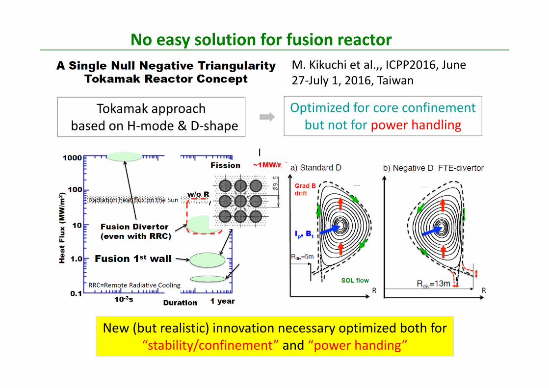
Collisional transport Turbulent transport
212TBnD iTD
B a
1~ ix a
1~ ~auto d
p~x
coll~
Opposite dependence to the goal (Bohm scaling)
~ EQ n T
What determines spatio‐temporal size of particle diffusion?
C‐2U analysis : from Tajima et al.
2 3 2
3/2~a B a BT T
Serious challenge : scaling nob ~ a
0.5 ~ 1
2
~ ii
aTB
22
~ ei
S
TaL B
Using 2~nT B assuming ~ 1O
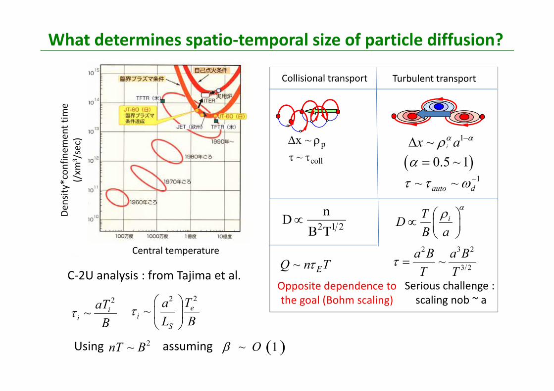
Tokamak : “quasi‐rigid” system, toroidal field is given from outside while a freedom to control poloidal field by current drive
“Rigid” or “soft” approach in designing device ? : Takamak case
ˆ ~ 1r qsq r
0 ~ rq
qrs
2 ~T
P
Br mq rR B n
( ) 2ˆ~ 2 exp
2n
nsx H i x i x
current
TB
pB
J
r
R
0
0.5
1.0
1.5
2.0
0 0.2 0.4 0.6 0.8 1
qmin
0 0.2 0.4 0.6 0.8 10
1
2
3
4
J q

• Mode-structure in non-uniform medium:(Extension to non-local ballooning theory)
jiexpjx rAx,r 00j
0th order eigen-function: 0r ,
2
0 0
ˆ exp -
2 sinfrk sA r r
r r
VkVkf
0,r • Representation of 2d-structure:
0 02 sin
ˆ frk sr r
21
r
max0
0 ˆ2
fr
r rk s
31
0 0 0cos
Tokamak is a system which allows meso scale fluctuation
1/2
~ˆ
T iLs
1~ˆ Tsk L
31
BΒ
E B
n=150
J.Y. Kim and M. Wakatani, PRL 73, 2200 (1994) Y. Kishimoto, J.Y. Kim, W. Horton, T. Tajima et al., Plasmas Phys. Controlled Fusion 41, A663 (1999)
radius
radius
ˆ1r sk
ˆ1r sk
mn
1mn1m
n
mn
1mn1m
n
0
(c)
rm+1 m+2m-2 m-1 ……( radius)m
n n nnn
0
Bloch angle
|s | 1~
T(r)
T(r)

“Constraint” on the profile and self‐similar relaxation• Constraint on the profile and relaxation
Kishimoto, Lebrun, Tajima, horton, Kim, PoP 3, 1289 (1996)
(No zonal flow) 110 ,rtT
1 0 0, 0T t r
1 ~ r L
~0rSelf-organized profile
110 , rtTRelaxation of
self-organized profile
Constraint on profile
Self‐similarity in the relaxation
(fast time scale)
(slow time scale)
perturbation
1 ~ r L・ ・
・
・・
• Avalanches on the self‐organized profile
2
0 1t t t
0 1r r r
slow relaxation
fast relaxation
micro-scalevariation
macro-scalevariation
11 1
1~ expT
rr L t
10
1~ exp
T
rTL t
• Spatio‐temporal hierarchy
1
01
~ expT
rT
L t
T TR L
Free energy is kept
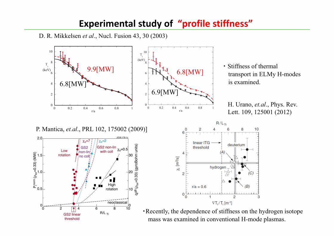
D. R. Mikkelsen et al., Nucl. Fusion 43, 30 (2003)
H. Urano, et.al., Phys. Rev. Lett. 109, 125001 (2012)
・ Stiffness of thermal transport in ELMy H-modes is examined.
9.9[MW] 6.8[MW]
6.8[MW]6.9[MW]
Experimental study of “profile stiffness”
・Recently, the dependence of stiffness on the hydrogen isotope mass was examined in conventional H-mode plasmas.
P. Mantica, et.al., PRL 102, 175002 (2009)]

Numerical laboratory for tokamak experimentsbased on global gyro‐kinetic modeling
Gyro‐Kinetic based Numerical Experimental Tokamak : GKNETImadera, Kishimoto et al. 25th FEC, TH/P5-8
• Flux driven full‐f global toroidal geometry with external source and sink
, , source sink collisionf f fH v H S S Ct v
R
R
• Electrostatic model with adiabatic electron• Full‐order of FLR effect • Conservative linear collision operator
*1 ||
0 0
1 1( ) ( )f
e i
f B dv dT r n r
• Vlasov solver : 4th‐order Morinishi scheme
▶ Basic equation system
▶ Numerical method
• Time integration : 4th‐order RK scheme• Parallelization: 5D (R‐Z‐φ‐v‐μ) MPI decomposition
Field equation is solved in real space (not k‐space)
Gyro‐Kinetic based Numerical Experiment of
Tokamak (GKNET)
Heat input and dissipation balance, leading to a self‐organized state
11

Transport events with different time and spatial scales Time : Intermittent (bursting) behavior due to various types of avalanches Space : self‐similarity in relaxation and self‐organization in profile
marginal state
(1)
(2b ) (2a )
3)
1) Spatially Localized avalanches propagating with fast time scale
2) Radially extended global bursts ranging for meso‐ to macro scale)
3) Spatially localized avalanches propagating with slow time scale coupled with ExB staircase, causing long time scale breathing in transport
1 2/c i T i~ L
1 2/c T i T~ L L
1 2/c T i~ L
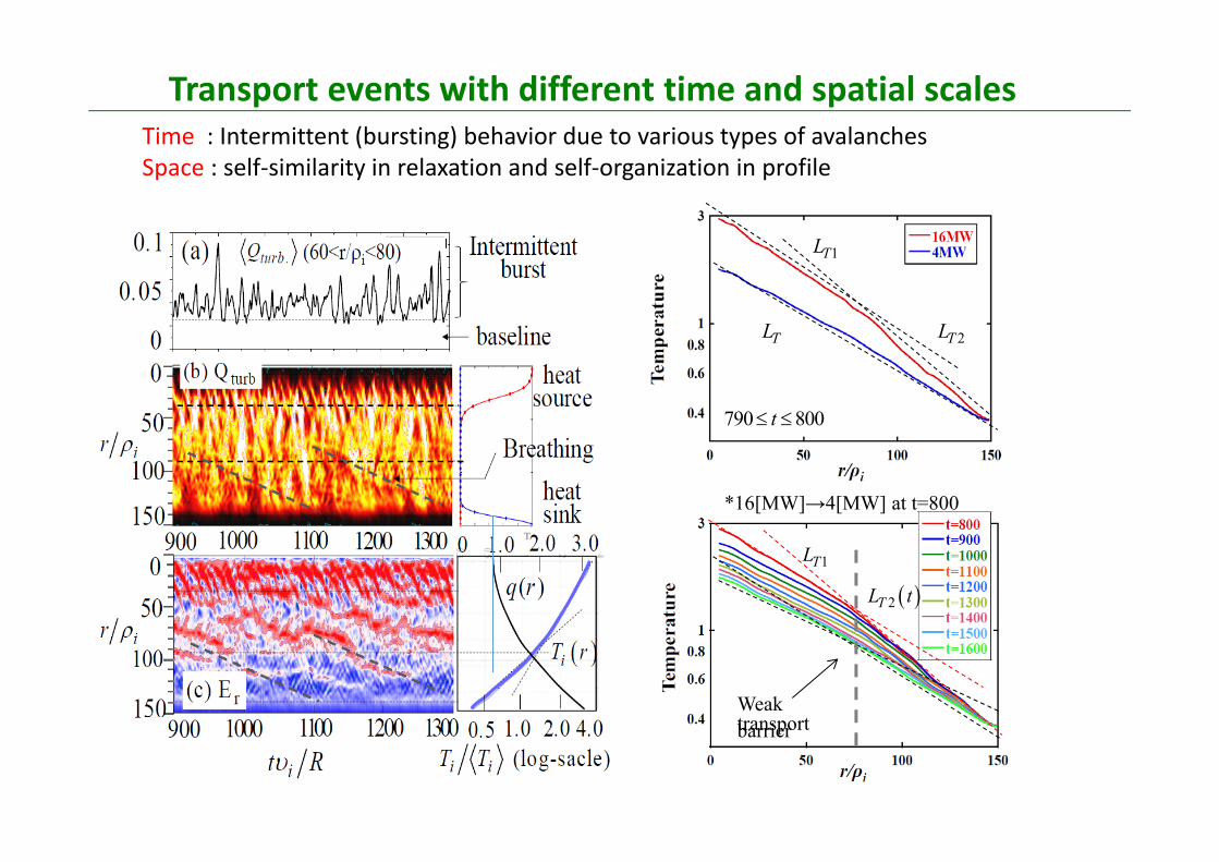
790 800t
2TL
1TL
TL
1TL
2TL t
*16[MW]→4[MW] at t=800
Weak transport barrier
Transport events with different time and spatial scales Time : Intermittent (bursting) behavior due to various types of avalanches Space : self‐similarity in relaxation and self‐organization in profile

Quasi‐periodic bursts due to the radially extended global mode
(A) t=566
(B) t=574
520 530 540 550 560 570 580 590 6000
50
100
150
ar
χi
20t ~
• Appearance of radially extended ballooning mode and subsequent growth, leading to a burst over macro‐scale
60 70r ~
A
B
C
(C) t=586
t=722
1 2T ir ~ L ~ a a
• Symmetry structurewith no titling:
0 0~
BΒ
0n=15
0 0 0cos 0rdE
dr60 70r ~

Symmetry recovery due to the cancellationbetween diamagnetic shear and mean ErxB shear
• The effect of global temperature profile is cancelled by that of global mean radial electric field, so that the symmetry is recovered and the growth is enhanced.
1dv2dv
r
r
E
r
1dv2dv
0 0 0cos~ ~
∓
/~ 0
2
/
∞
1dv2dv
1dv2dv
~c TL
– The system is self‐organized so as to expel the input power efficiently to outside by adjusting spatio‐temporal structure of turbulence and also profile.

Fig. 4. Effective heat diffusivity of three global gyrokinetic codes as a function of ρ∗. (copied from Fig.5 in Ref. 3)[3] Sarazin, et. al, Nucl. Fusion 51 (2011)
[Y. Idomura et al., Phys. Plasmas 21, 020706 (2014).]
GT5D code: Plasma size scaling at ITER‐size
Controversial discussion on Bohm/Gyro‐Bohm transition ?
Qtotal
Averaged heat fluxamong [1400, 1600]GKNET simulation
[1] Z. Lin et al., PRL 88, 195004 (2002).
Scaling using flux‐driven modeling

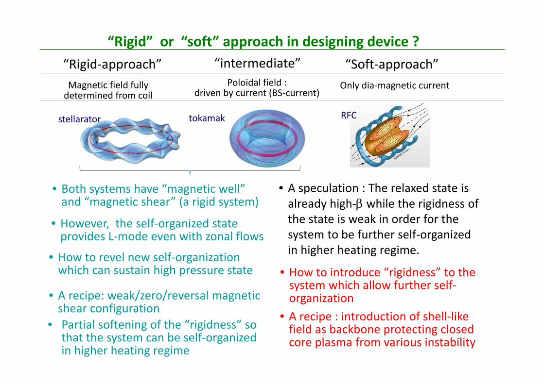
“Rigid‐approach” “Soft‐approach”“intermediate”Magnetic field fully determined from coil
Poloidal field : driven by current (BS‐current)
“Rigid” or “soft” approach in designing device ?
RFC
Only dia‐magnetic current
stellarator tokamak
• Both systems have “magnetic well” and “magnetic shear” (a rigid system)
• How to revel new self‐organization which can sustain high pressure state
• However, the self‐organized state provides L‐mode even with zonal flows

(A) S=0.2
(B) S=0.1 : weak magnetic shear
[Kishimoto,Li, et al., IAEA ’02]
0
2
4
6
8
10
2 3 4 5 6 7
e/[(
e/Ln)(c
Te/e
B)]
e
s= 0.1
s= 0.2(A )
(B )
s= 0.4
1 0 - 2
1 0 - 1
1 0 0
1 0 1
2 3 4 5 6 7
<|d
(z) /d
x|>2 /2
( a )
s= 0 .1
s= 0 .2
e
(B )
(A )
s= 0 .4
+
-
Self‐organization in high pressure state : magnetic shear
( )
( ) ( )
ZF
ZF turb ZF
EE E
fluctuation energy = turbulent part + laminar part
turbulence + zonal flow
turbulence
Formation of large scale structure

Coherency and phase between Ey and T
*~ E BQ T
Phase difference between potential and temperature
causes net transport Horton Rev. Mod. Physics 71,
735 (1999).
The phase of the large scale structure is locked so as not to cause transport

Comparison between LHD and Heliotron J (HJ)
Heliotron J
Heliotron J Inward‐shift configuration
LHD
HJ
W7‐X
TJ2
Magnetic hill MHD‐mode unstable
• Magnetic well →MHD‐mode stable
LHD TJ2 NCSX QPS Magnetic fields are designed to minimize
• Neo‐classical transport• MHD activity• Micro‐instability and turbulent transport
2r
q r
Ishizawa, Nakamura, Kishimoto et al. IAEA2016, Kyoto

Two families in Stellarator based on two key parameters
ˆ r qsq r
0wellD
Mercier magnetic well parameter
: magnetic well
0wellD : magnetic hill
Heliotron J
W7‐XHeliotronJHSX, TJ‐II LHD
CHSHelotronE
Heliotron J Inward‐shift configuration
GKV (EM) simulation (Local flux tube, trapped electron, collision )
Wave function along magnetic field
Stellarator : large growth rate in HJ than that in LHDEM‐ITG mode, TEM mode, Kinetic‐ballooning mode, micro‐tearing mode
Ishizawa, Nakamura, Kishimoto et al. IAEA2016, Kyoto

“Reciprocal relation” between linear and nonlinear dynamics
Heliotron JHeliotron J Inward‐shift configuration
Stellarator : lower transport (gyro‐Bohm unit) in HJ than that in LHD“Reciprocal relation” between linear and nonlinear dynamics
Ishizawa, Nakamura, Kishimoto et al. IAEA2016, Kyoto

Heliotron JHeliotron J Inward‐shift configuration
Stellarator : large fraction of zonal flows in HJ than that in LHD(cf. transition from turbulence dominate plasma to that of zonal flows )
Enhanced zonal flow generation in weak shear regime
( )
( ) ( )
ZF
ZF turb ZF
EE E
Ishizawa, Nakamura, Kishimoto et al. IAEA2016, Kyoto
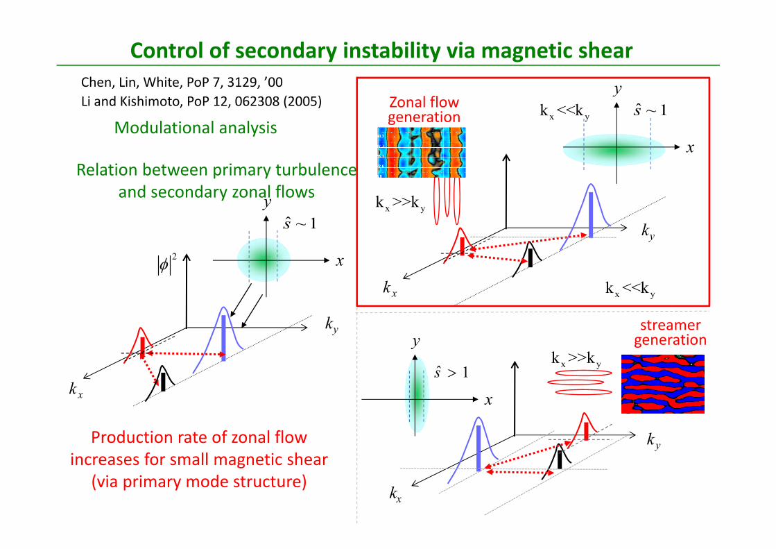
Modulational analysisLi and Kishimoto, PoP 12, 062308 (2005)
yk
xk
x yk >>k
yk
xk
yk
xk
x yk >>k
Chen, Lin, White, PoP 7, 3129, ’00
Control of secondary instability via magnetic shear
1~s
x
y
2
x yk <<k 1~s
x
y
x yk <<k
ˆ 1s
x
y
Zonal flow generation
streamer generation
Production rate of zonal flow increases for small magnetic shear
(via primary mode structure)
Relation between primary turbulence and secondary zonal flows

2 0.78nds
6 0.23ths 4 0.55ths
16MW case
500 550 600 650 700 750 800
0
50
100
150
ir
0
50
100
150
ir
Qturb(2nd)
Qturb(6th)
• Weak /zero and/or magnetic shear configuration
• Reversed magnetic shear configuration
Recipe in breaking self‐organized critical plasmas
Imadera, et al. IAEA2014, Kyoto

• Simulation condition
ElectronTemperature ,
magnetic shear
0.85
Ion density
Ion temperature
0 50 100 1500123
0
1
4
2
3
0 50 100 150
Weak/zero magnetic shear with momentum input
We compare two cases;(A) without momentum source (B) with momentum source at 90
/ //
,/
, 0.5 , , 0,
, ||, 2 /
0.5 ∥ ∥/
Parameter Value
⁄ 150⁄ 0.36
/ ⁄ 2.22
/⁄ 10.0
/⁄ 6.92
∗ 0.284 MW
45
Momentum source operator
/0 30 60 150
012090
0.2
0.4
0.6
0.8
1
oto, ICPP2016 (Taiwan), IAEA2016 (Kyoto)

ITB formation in weak magnetic shear plasma (1)
1
2
3
⁄
0 0.2 0.4 10.6 0.8/
0
No Input
Co Input
Ctr Input
HeatSource
Mom.Source
Sink
(A) Ion Temperature (B) Radial force balance
0 0.2 0.4 10.8
0.25
0
‐0.250.6
: ∥ :
/
(a.u.)
Co Input
② Momentum input by beam injection with co‐current toroidal rotation ① Flattening q‐profile in the core . ˆ ~ 0s
Requirements in causing ITB formation (self‐organization)
cf. qualitative agreement with the observations in the JET experiment
Imadera, Li, Kishimoto, ICPP2016 (Taiwan), IAEA2016 (Kyoto)

0/
3060901201500
/
306090120150
0 400 /
24001200800 1600 2000
[Y. Idomura, et al. Nucl. Fusion, 49, 065029 (2009).][M. Kikuchi and M. Azumi, Rev. Mod. Phys. 84, 1807 (2012).]
/
1.5
1.0
0.5
00 30 60 15090 120
/
/ ,
,• Clear correlation between the sign of
shear and the direction of avalanches can be observed.
• Strong shear triggered by toroidal rotation in outer region suppresses the turbulence, leading to an ITB formation.
t=2400
ITB formation in weak magnetic shear plasma (2)
Imadera, Li, Kishimoto, ICPP2016 (Taiwan), IAEA2016 (Kyoto)

1
2
3
⁄
0 0.2 0.4 10.6 0.8/
0
: t=1600(start co‐input): t=3200(stop co‐input)
: t=4000: t=4800
: : ∥ : :
0 0.2 10.8/
0.4 0.6 0 0.2 10.8/
0.4 0.6
0
0.1
‐0.1
0
0.1
‐0.1
Γ
Γ Γ
• The position of ITB is insensitive to the momentum source profile, which is determined only by the surface.
t=1600 t=3200
t=4000 t=4800
∗~
2 4
Reversed q
ITB formation in reversed magnetic shear plasma (1)
Imadera, Li, Kishimoto, ICPP2016 (Taiwan), IAEA2016 (Kyoto)
“Rigid‐approach” “Soft‐approach”“intermediate”Magnetic field fully determined from coil
Poloidal field : driven by current (BS‐current)
“Rigid” or “soft” approach in designing device ?
RFC
Only dia‐magnetic current
stellarator tokamak
• Both systems have “magnetic well” and “magnetic shear” (a rigid system)
• How to revel new self‐organization which can sustain high pressure state
• However, the self‐organized state provides L‐mode even with zonal flows
• A recipe: weak/zero/reversal magnetic shear configuration
• Partial softening of the “rigidness” so that the system can be self‐organized in higher heating regime
• A speculation : The relaxed state is already high‐ while the rigidness of the state is weak in order for the system to be further self‐organized in higher heating regime.
• How to introduce “rigidness” to the system which allow further self‐organization
• A recipe : introduction of shell‐like field as backbone protecting closed core plasma from various instability
“Soft‐approach”
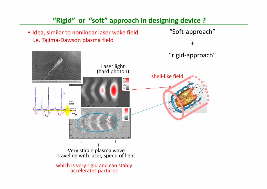
“Rigid” or “soft” approach in designing device ? • Idea, similar to nonlinear laser wake field, i.e. Tajima‐Dawson plasma field
Laser light (hard photon)
Very stable plasma wavetraveling with laser, speed of light
which is very rigid and can stably accelerates particles
“rigid‐approach”
+
shell‐like field
─ (quasi‐) rigid magnetic configuration with magnetic shear─ Rigid magnetic structure produces radially extended global mode
and self‐similar relaxation leading to L‐mode.
Summary
Transport in tokamak and stellarator is investigated using gyro‐kinetic modeling.
A freedom for changing magnetic shear is used in regulating transport.
─ Introduction of weak/zero magnetic, which corresponds to “softening the rigidness”, can lead to a new type of self‐organization in high pressure state.
Combination and/or mixture between soft approach and rigid approach is a key to exhibit self‐organization for confinement improvement.