TÜV Rheinland Energie und Umwelt...
24
TÜV Rheinland Energie und Umwelt GmbH Test Centre for Energy Appliances TÜV Rheinland Energie und Umwelt GmbH Am Grauen Stein D-51105 Cologne, Germany Managing Director Country Court Cologne Commercial Register HRB 56171 Telefon: Telefax: 0221-806-5200 0221-806–1349 Marcus Staude V 360 02 15.docx Report Nr. V 360.02/15 Extension of the SIL Assessment for Linear Actuators according to IEC 61508:2010 and IEC 61511:2004 Linear Actuator series: HDL-Series (HDLSRE, HDLSRR, HDLDA) L-Series (LSRE, LSRR, LDA) HDH-Series (HDHSRE, HDHSRR, HDHDA) H-Series (HSRE, HSRR, HDA) Company Automation Technology, LLC. Houston, Tx., USA 2015 This report may only be published and forwarded to third parties in its complete, unabridged form. The publication or dissemination of extracts, summaries, appraisals or any other adaptations and alterations, in particular for advertising purposes, is only permissible with the prior written permission of TÜV Rheinland. The publication of page 2 and 3 is permitted. The test results presented in this report refer solely to the test object stated as described on page 2. The report does not represent a general statement about the serial production of the test object and gives not an authorization for use of a TÜV Rheinland test- / certification mark.
Transcript of TÜV Rheinland Energie und Umwelt...
TÜV Rheinland Energie und Umwelt GmbH
Test Centre for Energy Appliances
TÜV Rheinland
Energie und Umwelt GmbH
Am Grauen Stein
D-51105 Cologne, Germany
Managing Director Country Court Cologne
Commercial Register HRB 56171
Telefon:
Telefax:
0221-806-5200
0221-806–1349
Marcus Staude V 360 02 15.docx
Report Nr. V 360.02/15
Extension of the SIL Assessment for Linear Actuators according to
IEC 61508:2010 and IEC 61511:2004
Linear Actuator series:
HDL-Series (HDLSRE, HDLSRR, HDLDA)
L-Series (LSRE, LSRR, LDA)
HDH-Series (HDHSRE, HDHSRR, HDHDA)
H-Series (HSRE, HSRR, HDA)
Company
Automation Technology, LLC.
Houston, Tx., USA
2015
This report may only be published and forwarded to third parties in its complete, unabridged form. The publication or
dissemination of extracts, summaries, appraisals or any other adaptations and alterations, in particular for advertising purposes, is only permissible with the prior written permission of TÜV Rheinland.
The publication of page 2 and 3 is permitted.
The test results presented in this report refer solely to the test object stated as described on page 2. The report does not represent a general statement about the serial production of the test object and gives not an authorization for use of a
TÜV Rheinland test- / certification mark.
TÜV Rheinland Energie und Umwelt GmbH
Test Centre for Energy Appliances
Order No. 21228508 page 2 / 24 Report No. V 360.02/15
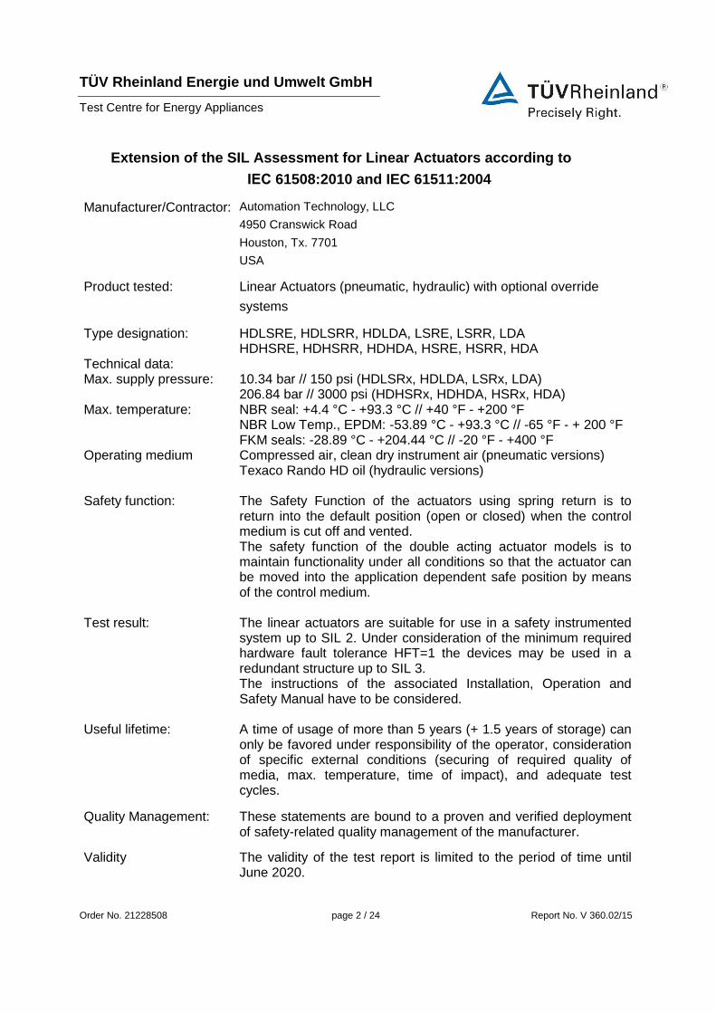
Extension of the SIL Assessment for Linear Actuators according to
IEC 61508:2010 and IEC 61511:2004
Manufacturer/Contractor: Automation Technology, LLC
4950 Cranswick Road
Houston, Tx. 7701
USA
Product tested: Linear Actuators (pneumatic, hydraulic) with optional override
systems
Type designation: HDLSRE, HDLSRR, HDLDA, LSRE, LSRR, LDA HDHSRE, HDHSRR, HDHDA, HSRE, HSRR, HDA
Technical data: Max. supply pressure: 10.34 bar // 150 psi (HDLSRx, HDLDA, LSRx, LDA)
206.84 bar // 3000 psi (HDHSRx, HDHDA, HSRx, HDA) Max. temperature: NBR seal: +4.4 °C - +93.3 °C // +40 °F - +200 °F
NBR Low Temp., EPDM: -53.89 °C - +93.3 °C // -65 °F - + 200 °F FKM seals: -28.89 °C - +204.44 °C // -20 °F - +400 °F
Operating medium Compressed air, clean dry instrument air (pneumatic versions) Texaco Rando HD oil (hydraulic versions)
Safety function: The Safety Function of the actuators using spring return is to return into the default position (open or closed) when the control medium is cut off and vented. The safety function of the double acting actuator models is to maintain functionality under all conditions so that the actuator can be moved into the application dependent safe position by means of the control medium.
Test result: The linear actuators are suitable for use in a safety instrumented system up to SIL 2. Under consideration of the minimum required hardware fault tolerance HFT=1 the devices may be used in a redundant structure up to SIL 3. The instructions of the associated Installation, Operation and Safety Manual have to be considered.
Useful lifetime: A time of usage of more than 5 years (+ 1.5 years of storage) can only be favored under responsibility of the operator, consideration of specific external conditions (securing of required quality of media, max. temperature, time of impact), and adequate test cycles.
Quality Management: These statements are bound to a proven and verified deployment of safety-related quality management of the manufacturer.
Validity The validity of the test report is limited to the period of time until June 2020.

TÜV Rheinland Energie und Umwelt GmbH
Test Centre for Energy Appliances
Order No. 21228508 page 3 / 24 Report No. V 360.02/15
The test results refer only to the test object. The test results do not represent any statement
with regard to the safety integrity level (SIL) of the final system. The suitability for certain
applications can only be realized through the evaluation of the respective safety-related
overall system, including all safety-related components, in accordance with IEC 61508 and
IEC 61511.
The test statement is valid for new linear actuators for a period of 5 years after commissioning
(+ 1.5 years storage). The test statement presupposes that during this period of time the linear
actuators are maintained and operated in accordance with the manufacturer’s specifications.
The Test Centre does not assume any further liability for application of the values
determined.
Cologne, 08.06.2015 Test Centre for Energy Appliances
Expert Review
i. A. i. A.
M.Eng. Christian Schneider Dr.-Ing. Jan Schumacher

TÜV Rheinland Energie und Umwelt GmbH
Test Centre for Energy Appliances
Order No. 21228508 page 4 / 24 Report No. V 360.02/15
Summary of technical safety characteristics
Table: Device specific values pneumatic spring return extend / retract HDL- / L-Series
(HDLSRR, HDLSRE, LSRR, LSRE)
Device-Specific Values Probability of Dangerous Failure on Demand
PFDspec 7.97 E-04
Test Interval Ti 1 a
Confidence Level 1-α 95 %
Safe Failure Fraction SFF 83.7 %
Hardware Fault Tolerance HFT 0
Diagnostic Coverage DC 0 %
Type of Sub System Type A
Mode of Operation Low Demand
Derived Values for 1oo1-Architecture
Assumed Demands per Year fnp 1 / a 1.14 E-04 / h
Total Failure Rate λS + λD 5.58 E-07 / h 558 FIT
Lambda Dangerous Detected λDD 0.00 E+00 / h 0 FIT
Lambda Dangerous Undetected λDU 9.10 E-08 / h 91 FIT
Lambda Safe λS 4.67 E-07 / h 467 FIT
Mean Time To Failures MTTF 1.79 E+06 h 205 a
Mean Time To Dangerous Failures MTTFD 1.10 E+07 h 1,255 a
Average Probability of Failure on Demand PFDavg 3.98 E-04
TÜV Rheinland Energie und Umwelt GmbH
Test Centre for Energy Appliances
Order No. 21228508 page 5 / 24 Report No. V 360.02/15
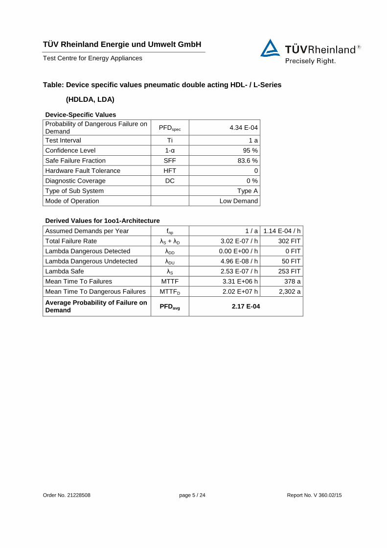
Table: Device specific values pneumatic double acting HDL- / L-Series
(HDLDA, LDA)
Device-Specific Values Probability of Dangerous Failure on Demand
PFDspec 4.34 E-04
Test Interval Ti 1 a
Confidence Level 1-α 95 %
Safe Failure Fraction SFF 83.6 %
Hardware Fault Tolerance HFT 0
Diagnostic Coverage DC 0 %
Type of Sub System Type A
Mode of Operation Low Demand
Derived Values for 1oo1-Architecture
Assumed Demands per Year fnp 1 / a 1.14 E-04 / h
Total Failure Rate λS + λD 3.02 E-07 / h 302 FIT
Lambda Dangerous Detected λDD 0.00 E+00 / h 0 FIT
Lambda Dangerous Undetected λDU 4.96 E-08 / h 50 FIT
Lambda Safe λS 2.53 E-07 / h 253 FIT
Mean Time To Failures MTTF 3.31 E+06 h 378 a
Mean Time To Dangerous Failures MTTFD 2.02 E+07 h 2,302 a
Average Probability of Failure on Demand PFDavg 2.17 E-04
TÜV Rheinland Energie und Umwelt GmbH
Test Centre for Energy Appliances
Order No. 21228508 page 6 / 24 Report No. V 360.02/15
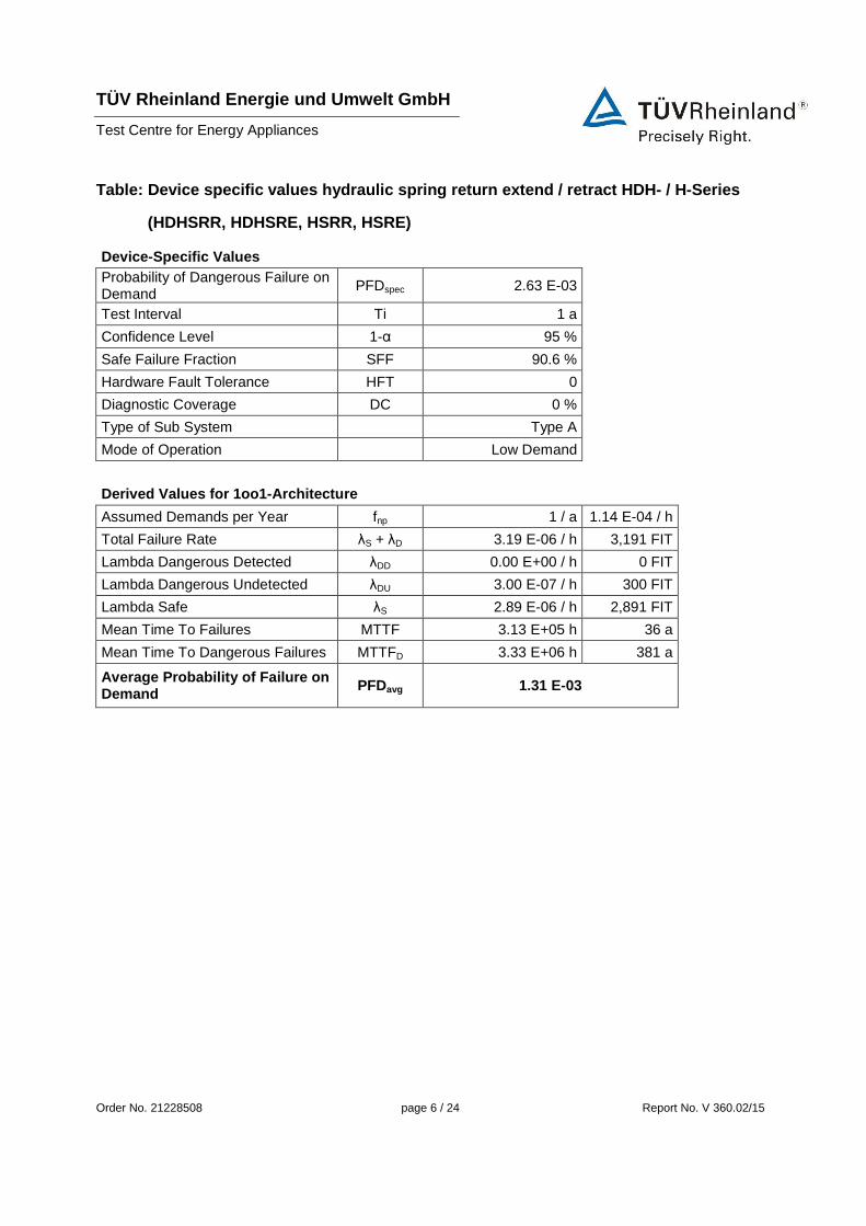
Table: Device specific values hydraulic spring return extend / retract HDH- / H-Series
(HDHSRR, HDHSRE, HSRR, HSRE)
Device-Specific Values Probability of Dangerous Failure on Demand
PFDspec 2.63 E-03
Test Interval Ti 1 a
Confidence Level 1-α 95 %
Safe Failure Fraction SFF 90.6 %
Hardware Fault Tolerance HFT 0
Diagnostic Coverage DC 0 %
Type of Sub System Type A
Mode of Operation Low Demand
Derived Values for 1oo1-Architecture
Assumed Demands per Year fnp 1 / a 1.14 E-04 / h
Total Failure Rate λS + λD 3.19 E-06 / h 3,191 FIT
Lambda Dangerous Detected λDD 0.00 E+00 / h 0 FIT
Lambda Dangerous Undetected λDU 3.00 E-07 / h 300 FIT
Lambda Safe λS 2.89 E-06 / h 2,891 FIT
Mean Time To Failures MTTF 3.13 E+05 h 36 a
Mean Time To Dangerous Failures MTTFD 3.33 E+06 h 381 a
Average Probability of Failure on Demand PFDavg 1.31 E-03

TÜV Rheinland Energie und Umwelt GmbH
Test Centre for Energy Appliances
Order No. 21228508 page 7 / 24 Report No. V 360.02/15
Table: Device specific values hydraulic double acting HDH- / H-Series
(HDHDA, HDA)
Device-Specific Values Probability of Dangerous Failure on Demand
PFDspec 1.76 E-03
Test Interval Ti 1 a
Confidence Level 1-α 95 %
Safe Failure Fraction SFF 83.6 %
Hardware Fault Tolerance HFT 0
Diagnostic Coverage DC 0 %
Type of Sub System Type A
Mode of Operation Low Demand
Derived Values for 1oo1-Architecture
Assumed Demands per Year fnp 1 / a 1.14 E-04 / h
Total Failure Rate λS + λD 1.22 E-06 / h 1,224 FIT
Lambda Dangerous Detected λDD 0.00 E+00 / h 0 FIT
Lambda Dangerous Undetected λDU 2.01 E-07 / h 201 FIT
Lambda Safe λS 1.02 E-06 / h 1,024 FIT
Mean Time To Failures MTTF 8.17 E+05 h 93 a
Mean Time To Dangerous Failures MTTFD 4.98 E+06 h 568 a
Average Probability of Failure on Demand PFDavg 8.80 E-04
TÜV Rheinland Energie und Umwelt GmbH
Test Centre for Energy Appliances
Order No. 21228508 page 8 / 24 Report No. V 360.02/15
Content
1. Task Definition 9
1.1 Test Basis 9
1.2 Previous Reports 10
2. Description of Test Item 11
2.1 Design Variants of Linear Actuators 13
2.2 Optional Manual Overrides 14
2.3 Safety Function 15
3. Assessment 16
3.1 Mode of Operation 16
3.2 Type of Subsystem 16
3.3 Diagnostic Coverage 16
3.4 Hardware Fault Tolerance 16
3.5 Common Cause Factor 16
3.6 Safe Failure Fraction 17
3.7 Calculated values 18
3.8 Systematic Safety Integrity 20
3.9 Requirements for the prevention of failures 20
3.10 Requirements for the control of systematic failures 21
4. Test Statement 22
TÜV Rheinland Energie und Umwelt GmbH
Test Centre for Energy Appliances
Order No. 21228508 page 9 / 24 Report No. V 360.02/15
1. Task Definition
The aim of the appraisal is to determine the suitability of the test items for utilization in safety-
related systems in accordance with IEC 61508:2010 and IEC 61511:2004 for operating
modes with a low demand on the safety function (low demand mode).
The linear actuators inspected are used in safety-related systems as part of a final controlling
device (shut off valve, control valve). This extension is carried out on the assessment of the
HDLSRE, HDLSRR, HDLDA, HDHSRE, HDHSRR and HDHDA heavy duty series
documented in the report V 360 2010 S1 (dated 2010-08-30) which was based on the
determination of the safe failure fraction of the test item. No constructional changes were
made in the assessed type series. Furthermore the versions for use on control valves (LSRE,
LSRR, LDA, HSRE, HSRR, HDA) shall be assessed and included into this report.
The safety function of the actuators using spring return is to return into the default position
(open or closed) when the control medium is cut off and vented.
The safety function of the double acting actuator models is to maintain functionality under all
conditions so that the actuator can be moved into the application dependent safe position by
means of the control medium.
The evaluation of the test items was carried out on the basis of
- manufacturer declaration of constructive / design / material analogousness of the test
items compared to test report V 360 2010 S1
- an updated Failure Mode and Effect Analysis (FMEA) for recalculating the SFF
- statistically evaluation of sales and customer complaint tables
- the previous assessment and results as described in report V 360 2010 S1
- the certified quality management system of the manufacturer.
The test results refer only to the mechanical safety function of the test object. The suitability
for certain applications can only be realized through the evaluation of the respective safety-
related overall system, including all safety-related components, in accordance with the
relevant standard.
1.1 Test Basis
[N1] IEC 61508 Parts 1-2, 4-7:2010
[N2] IEC 61511 Parts 1-3:2004
TÜV Rheinland Energie und Umwelt GmbH
Test Centre for Energy Appliances
Order No. 21228508 page 10 / 24 Report No. V 360.02/15
1.2 Previous Reports
Types Report -No.
HDLSRE, HDLSRR, HDLDA, HDHSRE,
HDHSRR, HDHDA
V 360 2010 S1 (2010-08-30)
TÜV Rheinland Energie und Umwelt GmbH
Test Centre for Energy Appliances
Order No. 21228508 page 11 / 24 Report No. V 360.02/15
2. Description of Test Item
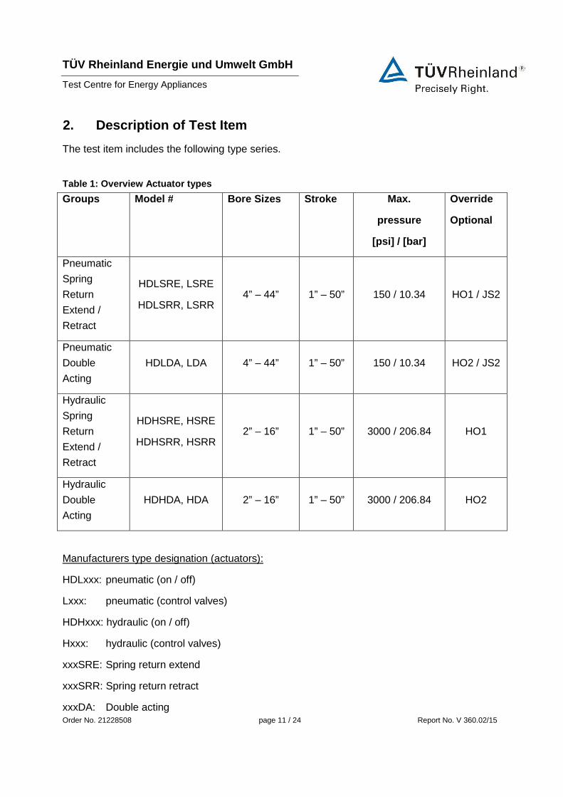
The test item includes the following type series.
Table 1: Overview Actuator types
Groups Model # Bore Sizes Stroke Max.
pressure
[psi] / [bar]
Override
Optional
Pneumatic
Spring
Return
Extend /
Retract
HDLSRE, LSRE
HDLSRR, LSRR 4” – 44” 1” – 50” 150 / 10.34 HO1 / JS2
Pneumatic
Double
Acting
HDLDA, LDA 4” – 44” 1” – 50” 150 / 10.34 HO2 / JS2
Hydraulic
Spring
Return
Extend /
Retract
HDHSRE, HSRE
HDHSRR, HSRR 2” – 16” 1” – 50” 3000 / 206.84 HO1
Hydraulic
Double
Acting
HDHDA, HDA 2” – 16” 1” – 50” 3000 / 206.84 HO2
Manufacturers type designation (actuators):
HDLxxx: pneumatic (on / off)
Lxxx: pneumatic (control valves)
HDHxxx: hydraulic (on / off)
Hxxx: hydraulic (control valves)
xxxSRE: Spring return extend
xxxSRR: Spring return retract
xxxDA: Double acting

TÜV Rheinland Energie und Umwelt GmbH
Test Centre for Energy Appliances
Order No. 21228508 page 12 / 24 Report No. V 360.02/15
The test items are linear actuators. In the normal mode of operation the test items are
actuated by means of the respective control medium. For the pneumatic versions clean, dry
air is used, for the hydraulic versions Texaco Rando HD oil is used as control medium.
The difference between the L- and LD-Series respectively the H- and HD-Series is the
intended use (control valve, on/off application) and the pressure rating. Their functional
behaviour and constructional design is the same.
The examined type series contain optional override mechanisms. In override mode the test
items can be actuated by a hand wheel override (JS2) or a hydraulic override (HO2 / HO1).
Hydraulic and manual overrides ensure the ability to operate the actuator upon complete loss
of electricity or air / hydraulic pressure.
The hand wheel override uses a worm gear and a thrust rod to move the actuator without
control medium. The hand wheel override is coupled via a screw with the actuator. In normal
mode the screw is retracted and the hand wheel override and the actuator are uncoupled.
The hydraulic override uses a hand pump which fills a hydraulic cylinder installed on top of the
pneumatic cylinder / spring compartment of the actuator. The hydraulic cylinder contains a
piston connected to the actuators thrust rod. By filling one side of the hydraulic cylinder using
the hand pump the actuator is moved in the corresponding direction. In normal mode of
operation the hydraulic cylinder is empty. The piston inside the hydraulic cylinder remains
connected to thrust rod.
The following options exist for the used elastomeric sealings.
Table 2: Overview used Sealings
Permissible operating temperature [A40, A41]
Sealing Option °F °C
NBR Sealings +40 – +200 +4.4 – +93.3
NBR Low Temp Sealings -65 – +200 -53.89 – +93.3
EPDM -65 – +200 -53.89 – +93.3
TÜV Rheinland Energie und Umwelt GmbH
Test Centre for Energy Appliances
Order No. 21228508 page 13 / 24 Report No. V 360.02/15
FKM Sealings -20 – +400 -28.89 – +204.44
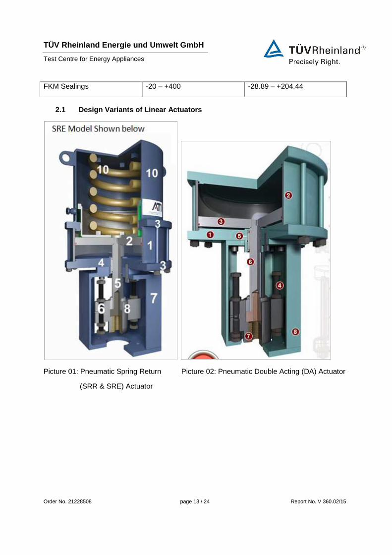
2.1 Design Variants of Linear Actuators
Picture 01: Pneumatic Spring Return Picture 02: Pneumatic Double Acting (DA) Actuator
(SRR & SRE) Actuator

TÜV Rheinland Energie und Umwelt GmbH
Test Centre for Energy Appliances
Order No. 21228508 page 14 / 24 Report No. V 360.02/15
Picture 03: Hydraulic Spring Return Picture 04: Hydraulic Double Acting (DA) Actuator
(SRR & SRE) Actuator
2.2 Optional Manual Overrides
JS2 Override:
- capable of extending or retracting the actuator
- can be engaged at any position from full open to full closed
- entire mechanism incorporated in actuator adapter
- allows for removal or service of the power cylinder while maintaining complete
control of the valve

TÜV Rheinland Energie und Umwelt GmbH
Test Centre for Energy Appliances
Order No. 21228508 page 15 / 24 Report No. V 360.02/15
HO1 Override:
- one way hydraulic override for use on spring return actuators
- compresses spring and operates valve
- spring force is used to move valve to failure position
HO2 Override:
- used on double acting actuators
- capable of extending or retracting actuator
- allows for precise speed control by regulating flow of hydraulic fluid in system
2.3 Safety Function
The safety function of the actuators using spring return is to return into the default position
(open or closed) when the control medium is cut off and vented.
The safety function of the double acting actuator models is to maintain functionality under all
conditions so that the actuator can be moved into the application dependent safe position by
means of the control medium.
TÜV Rheinland Energie und Umwelt GmbH
Test Centre for Energy Appliances
Order No. 21228508 page 16 / 24 Report No. V 360.02/15
3. Assessment
To assess the capability of the test item for its use in safety related applications several
parameters are necessary. The following chapter explains how all parameters of the
certificate have been determined.
3.1 Mode of Operation
The operation mode of the test item can be classified as an operation mode with a low rate of
demand in accordance with IEC 61508-4, 3.5.16.
LDM
3.2 Type of Subsystem
The system is classified as Type A in accordance with IEC 61508-2, Section 7.4.4.1.2.
The FMEA of the test items has shown that the failure behavior of all components is defined
sufficiently.
Due to the proven in use data and customer complaints of the test item, the behavior of the
test item under fault conditions can be suspected as completely determined.
Type A
3.3 Diagnostic Coverage
The test item itself does not contain any diagnostic measures. If diagnosis is required for the
safety function of the test item then this must be provided through external measures as part
of the safety-related overall system.
DC = 0 %
3.4 Hardware Fault Tolerance
The test item is a single-channel system and consequently itself has no hardware fault
tolerance. If a hardware fault tolerance is necessary then a multichannel structure has to be
stipulated as required.
HFT = 0
3.5 Common Cause Factor
The βint-factor states how many failures in redundant architectures can be lead back on a
common cause. It was calculated acc. IEC 61508-6, table D.1.
βint = 10 %
TÜV Rheinland Energie und Umwelt GmbH
Test Centre for Energy Appliances
Order No. 21228508 page 17 / 24 Report No. V 360.02/15
3.6 Safe Failure Fraction
The safe failure fraction (SFF) states the ratio of safe failures to all possible failures of the
safety function of the component. A safe failure of the safety function is a failure that does not
lead to a dangerous situation. Therefore dangerous detected and dangerous excluded failures
are also on the top of the fraction bar.
A reevaluation of all failures was done within the FMEA with the alternative method from
EN 161:2011/A3:2013 which pays respect to systematic and random failures.
For the FMEA one type of each actuator group has been select as a worst case scenario for
the whole group. The following types have been selected.
Table 3: Types used for FMEA
Types used for FMEA
Group Type
Pneumatic spring return HDLSRE with JS2
Pneumatic double acting HDLDA with HO2
Hydraulic spring return HDHSRE
The different versions of the pneumatic linear actuators HDLSRR, HDLSRE (heavy duty, on /
off application) and LSRR, LSRE (control valve) were considered as technically identical and
only differ from the intended use and intended operating conditions. The same was assumed
for the double acting versions and the hydraulic versions.
During the FMEA only the normal operating mode for the actuators with disengaged override
systems has been considered. Since the hand wheel override (JS1, JS2) is uncoupled from
the actuator in normal mode of operation it does not generate additional possible failures. The
hydraulic override (HO1, HO2) does generate additional possible failures since during normal
operation the piston of the hydraulic override remains connected to the thrust rod of the
actuator.
��� =
∑λ���� + ∑λ����� ���������+∑ λ����� ����� ���
∑λ���� + ∑λ����� �

TÜV Rheinland Energie und Umwelt GmbH
Test Centre for Energy Appliances
Order No. 21228508 page 18 / 24 Report No. V 360.02/15
Using the specified types, the FMEA lead to the following results.
Table 4: determined SFF
FMEA results
Group Safe Failures Dangerous Failures SFF
Pneumatic spring
return extend / retract
41 8 83.7 %
Pneumatic double
acting(X)
42 9 82.4 %
Hydraulic spring
return extend / retract
58 6 90.6 %
Hydraulic double
acting(X)
42 9 82.4 %
JS2 - - -
HO2, HO1 9 1 90.0 %
(X)In Addition to the failures considered in this report, possible failures for the pressure supply have to be considered for the
double acting types HDLDA , LDA and HDHDA, HDA.
The number of safe and dangerous failure for the hydraulic override (HO1, HO2) has to be
added to any actuator equipped with this override and the safe failure fraction has to be
recalculated according to the result of this addition.
In addition to the numbers from the FMEA additional failures that can lead to a failure of the
control medium supply have to be considered for the double acting design.
3.7 Calculated values
Failure rates have been calculated by results of the proven in use data and the customer
complaint list (years 2010-2014) submitted by the manufacturer and the recalculated SFF by
means of an updated FMEA. According to the manufacturer ca. 25 % of all sold units are used
in safety relevant applications (LDM with 1 demand per year). In total 11.5 demands per year
were considered for calculation.
TÜV Rheinland Energie und Umwelt GmbH
Test Centre for Energy Appliances
Order No. 21228508 page 19 / 24 Report No. V 360.02/15
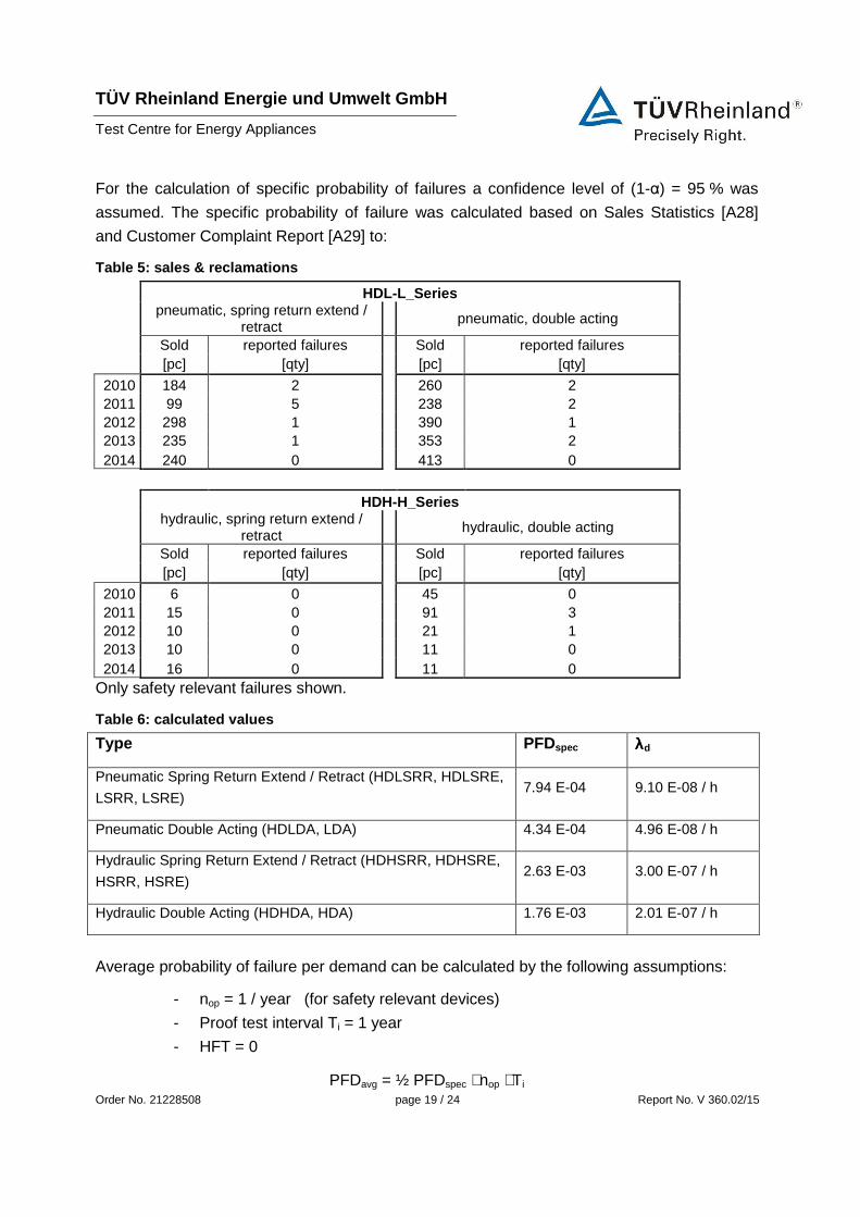
For the calculation of specific probability of failures a confidence level of (1-α) = 95 % was
assumed. The specific probability of failure was calculated based on Sales Statistics [A28]
and Customer Complaint Report [A29] to:
Table 5: sales & reclamations
HDL-L_Series pneumatic, spring return extend /
retract pneumatic, double acting
Sold reported failures Sold reported failures [pc] [qty] [pc] [qty]
2010 184 2 260 2 2011 99 5 238 2 2012 298 1 390 1 2013 235 1 353 2 2014 240 0 413 0
HDH-H_Series hydraulic, spring return extend /
retract hydraulic, double acting
Sold reported failures Sold reported failures [pc] [qty] [pc] [qty]
2010 6 0 45 0 2011 15 0 91 3 2012 10 0 21 1 2013 10 0 11 0 2014 16 0 11 0
Only safety relevant failures shown.
Table 6: calculated values
Type PFDspec λλλλd
Pneumatic Spring Return Extend / Retract (HDLSRR, HDLSRE,
LSRR, LSRE) 7.94 E-04 9.10 E-08 / h
Pneumatic Double Acting (HDLDA, LDA) 4.34 E-04 4.96 E-08 / h
Hydraulic Spring Return Extend / Retract (HDHSRR, HDHSRE,
HSRR, HSRE) 2.63 E-03 3.00 E-07 / h
Hydraulic Double Acting (HDHDA, HDA) 1.76 E-03 2.01 E-07 / h
Average probability of failure per demand can be calculated by the following assumptions:
- nop = 1 / year (for safety relevant devices)
- Proof test interval Ti = 1 year
- HFT = 0
PFDavg = ½ PFDspec ⋅ nop ⋅ Ti

TÜV Rheinland Energie und Umwelt GmbH
Test Centre for Energy Appliances
Order No. 21228508 page 20 / 24 Report No. V 360.02/15
Table 7: calculated PFD avg
Type PFDavg
Pneumatic Spring Return Extend / Retract (HDLSRR, HDLSRE,
LSRR, LSRE) 3.98 E-04
Pneumatic Double Acting (HDLDA, LDA) 2.17 E-04
Hydraulic Spring Return Extend / Retract (HDHSRR, HDHSRE,
HSRR, HSRE) 1.31 E-03
Hydraulic Double Acting (HDHDA, HDA) 8.80 E-04
3.8 Systematic Safety Integrity
The systematic safety integrity has been proved by a valid ISO 9001 certificate (Annex A 30)
and by installation, operation and maintenance instructions (Annex A 14 to A 19) as well as
the SIL users guide (Annex A46).
To be able to use a component in a safety related system according to IEC 61508, this
component has to fulfil requirements regarding the systematic safety integrity to proof an
adequate safety against systematic failures.
A systematic failure is defined in accordance with IEC 61508-4 as a failure whose cause can
be clearly identified. Examples for causes of systematic failures are errors during design,
assembly and installation of the product.
Possible causes for systematic failures have been identified during the FMEA.
3.9 Requirements for the prevention of failures
To prevent failures because of errors during the design of the component a suitable range of
methods has to be employed according to IEC 61508-2. It is the opinion of the test centre,
that a quality management system fulfilling the requirements of ISO 9001 [A30] is a suitable
means to meet these requirements.
TÜV Rheinland Energie und Umwelt GmbH
Test Centre for Energy Appliances
Order No. 21228508 page 21 / 24 Report No. V 360.02/15
The specific measures employed to prevent specific systematic failures have been identified
and documented in the FMEA.
3.10 Requirements for the control of systematic failures
In addition to the requirements for the prevention of systematic failures IEC 61508-2 presents
requirements to ensure that the design of the booster relays is tolerant against:
1. the remaining design errors present, unless it is possible to exclude the possibility ofremaining design errors.
2. stress induced by the ambient conditions of the examined system3. errors made by the operator of the equipment.
It is the opinion of the test centre, that it is a valid assumption, that no design errors remain in
the mechanical component of the examined actuator, because the test item consists of well-
known mechanical components and a long history and experience in the use of this
components and their design exists. Therefore the first point can be seen as fulfilled. The
maintenance interval of 5 years specified in the Installation, Operation and Maintenance
Manual seems suitable to detect aging effects before these effects can lead to a dangerous
condition.
The ambient conditions of the actuators are well defined and do not present a harmful
condition for the mechanical part of the actuators as documented by the specification of the
sealing. Therefore the second point can be seen as fulfilled.
Errors made by the operator of the equipment might prove to be harmful. Since the “operator”
of the actuator is a control system, it is valid to pass this requirement on to the design of this
system. Information for the safe use of the manual override is included in the operating
manual. Therefore all three points can be seen as fulfilled.
TÜV Rheinland Energie und Umwelt GmbH
Test Centre for Energy Appliances
Order No. 21228508 page 22 / 24 Report No. V 360.02/15
4. Test Statement
The
linear actuators
of the type series
HDLSRE, HDLSRR, HDLDA,
LSRE, LSRR, LDA
HDHSRE, HDHSRR, HDHDA
HSRE, HSRR, HDA
with optionally installed
override systems
of type series
JS2 and HO1 / HO2
of the manufacturer Automation Technology, LLC
4950 Cranswick Road
Houston, Tx., 77041
USA
are suitable for use in a safety instrumented system up to SIL 2 according to IEC 61508:2010
and IEC 61511:2004.
Under consideration of the minimum hardware fault tolerance HFT =1 the actuators may be
used in a redundant structure up to SIL 3.

TÜV Rheinland Energie und Umwelt GmbH
Test Centre for Energy Appliances
Order No. 21228508 page 23 / 24 Report No. V 360.02/15
List of Inspected Documents
A01 Linear Actuators – Product Overview Brochure
A02 Assembly Drawing & Material List HDHSRR, No. 27305, Rev. A 4/23/15
A03 Assembly Drawing & Material List HDHSRE, No. 27304, Rev. A 4/23/15
A04 Assembly Drawing & Material List HDHDA, No. 27306, Rev. A 4/23/15
A05 Assembly Drawing & Material List HSRR, No. 27308, Rev. A 4/23/15
A06 Assembly Drawing & Material List HSRE, No. 27307, Rev. A 4/23/15
A07 Assembly Drawing & Material List HDA, No. 27309, Rev. A 4/23/15
A08 Assembly Drawing & Material List HDLSRR, No. 26414, Rev. A 4/24/15
A09 Assembly Drawing & Material List HDLSRE, No. 27296, Rev. A 4/24/15
A10 Assembly Drawing & Material List HDLDA, No. 27298, Rev. A 4/24/15
A11 Assembly Drawing & Material List LSRR, No. 27302, Rev. A 4/24/15
A12 Assembly Drawing & Material List LSRE, No. 27299, Rev. A 4/24/15
A13 Assembly Drawing & Material List LDA, No. 27303, Rev. A 4/24/15
A14 Instruction / Operation / Maintenance Manual, Hydraulic Type SRR, IOM 1005 Rev A
A15 Instruction / Operation / Maintenance Manual, Hydraulic Type SRE, IOM 1004 Rev A
A16 Instruction / Operation / Maintenance Manual, Hydraulic Type DA, IOM 1006 Rev B
A17 Instruction / Operation / Maintenance Manual, Pneumatic Type SRR, IOM 1002 Rev C
A18 Instruction / Operation / Maintenance Manual, Pneumatic Type SRE, IOM 1001 Rev B
A19 Instruction / Operation / Maintenance Manual, Pneumatic Type DA, IOM 1003 Rev C
A20 FMEA HDH-SRE, TÜV Rheinland
A21 FMEA HDLDA, TÜV Rheinland
A22 FMEA HDL-JS2, TÜV Rheinland
A23 PFD Calculation HDL-L-Series spring return extension, TÜV Rheinland
A24 PFD Calculation HDL-L-Series double acting, TÜV Rheinland
A25 PFD Calculation HDH-H-Series spring return extension, TÜV Rheinland
A26 PFD Calculation HDH-H-Series double acting, TÜV Rheinland
A27 ATI Sales Presentation
TÜV Rheinland Energie und Umwelt GmbH
Test Centre for Energy Appliances
Order No. 21228508 page 24 / 24 Report No. V 360.02/15
A28 Sales Statistic, ATI, 2010-2014, L-/HDL-/H-/HDH-Series
A29 Customer Complaint Report Log, 2010-2014
A30 ISO 9001 Certificate, ATI, valid until 18. Sept. 2015
A31 QM-Certificate acc. Directive 97/23/EC Module H, ATI, valid until 18. Sept. 2015
A32 Report V360 2010 S1, Examination of Suitability acc. IEC 61508, TÜV Rheinland,
2010-10-06
A33 Private Label Agreement ATI / Fisher Controls International LLC, Mail 9 March 2015
A34 Instruction / Operation / Maintenance Manual, Type DA with hydraulic overrides HO2,
IOM 1017 Rev B
A35 ATI Technical Description / Hydraulic Oil Specs, 2010
A36 Test and Inspection Procedure, MP1015, Rev. J 6/16/14
A37 Test and Inspection Report, MF1001, Rev. M
A38 Final Inspection Report QF0009 Rev. J 4/7/15
A39 Order Entry Engineering Form, S-115, 12/6/02
A40 Seal Documentation, Buna / Low Temp Buna / Viton / PTFE wear band
(1990/1985/2000)
A41 Seal Documentation, EPDM (-70 to 300 °F), Buna (-35 to +250 °F), Viton (-15 to
+400 °F)
A42 Quality Assurance Manual, ISO 9001-2008, Rev. E, 6/2/14
A43 General Product Stress Analysis, #EP4001, Rev. C 4/19/13
A44 Manufacturer Declaration of unchanged design, 2015-05-13
A45 Confirmation only 25% of sold actuators used in safety relevant applications, 2015-05-
26
A46 Calculation β-factor
A47 SIL Handbook