
Thomas & Betts Microlectric Meter Sockets -...
82
Transcript of Thomas & Betts Microlectric Meter Sockets -...

www.youtube.com/user/ebhorsman
Visit our Shop Online
ebhorsman.com
proud distributorof
w w w . t n b . c a D1
Meter Sockets
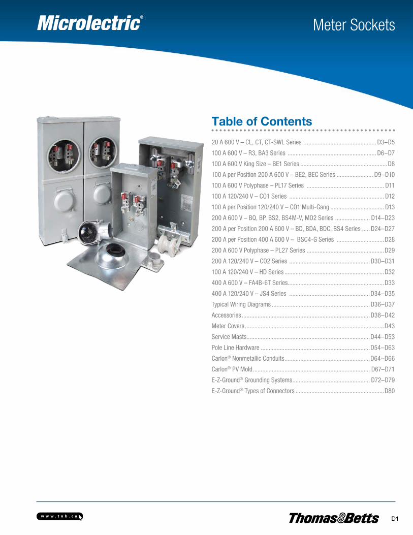
Table of Contents
20 A 600 V – CL, CT, CT-SWL Series .............................................. D3–D5
100 A 600 V – R3, BA3 Series ........................................................ D6–D7
100 A 600 V King Size – BE1 Series .......................................................D8
100 A per Position 200 A 600 V – BE2, BEC Series ....................... D9–D10
100 A 600 V Polyphase – PL17 Series ................................................. D11
100 A 120/240 V – CO1 Series ............................................................ D12
100 A per Position 120/240 V – CO1 Multi-Gang .................................. D13
200 A 600 V – BQ, BP, BS2, BS4M-V, MO2 Series ...................... D14–D23
200 A per Position 200 A 600 V – BD, BDA, BDC, BS4 Series ..... D24–D27
200 A per Position 400 A 600 V – BSC4-G Series ..............................D28
200 A 600 V Polyphase – PL27 Series .................................................D29
200 A 120/240 V – CO2 Series ...................................................D30–D31
100 A 120/240 V – HD Series ...............................................................D32
400 A 600 V – FA4B-6T Series.............................................................D33
400 A 120/240 V – JS4 Series ...................................................D34–D35
Typical Wiring Diagrams ..............................................................D36–D37
Accessories .................................................................................D38–D42
Meter Covers ........................................................................................D43
Service Masts ..............................................................................D44–D53
Pole Line Hardware .....................................................................D54–D63
Carlon® Nonmetallic Conduits ......................................................D64–D66
Carlon® PV Mold .......................................................................... D67–D71
E-Z-Ground® Grounding Systems ................................................. D72–D79
E-Z-Ground® Types of Connectors ........................................................D80
w w w . t n b . c aD2
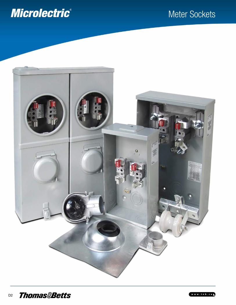
Meter Sockets
w w w . t n b . c a D3
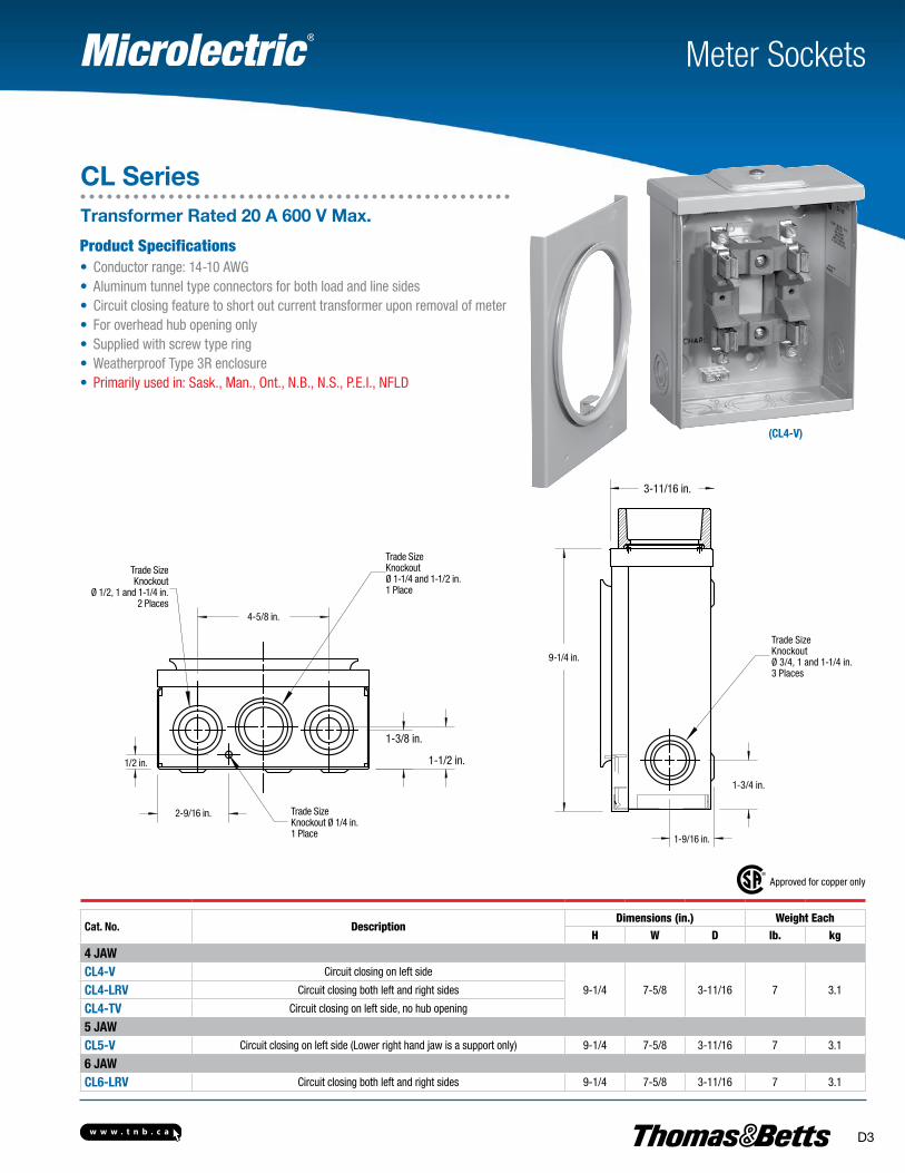
(CL4-V)
Meter Sockets
CL SeriesTransformer Rated 20 A 600 V Max.
Product Specifications• Conductor range: 14-10 AWG• Aluminum tunnel type connectors for both load and line sides• Circuit closing feature to short out current transformer upon removal of meter• For overhead hub opening only• Supplied with screw type ring• Weatherproof Type 3R enclosure• Primarily used in: Sask., Man., Ont., N.B., N.S., P.E.I., NFLD
Approved for copper only
Cat. No. DescriptionDimensions (in.) Weight Each
H W D lb. kg
4 JAWCL4-V Circuit closing on left side
9-1/4 7-5/8 3-11/16 7 3.1CL4-LRV Circuit closing both left and right sides
CL4-TV Circuit closing on left side, no hub opening
5 JAWCL5-V Circuit closing on left side (Lower right hand jaw is a support only) 9-1/4 7-5/8 3-11/16 7 3.1
6 JAWCL6-LRV Circuit closing both left and right sides 9-1/4 7-5/8 3-11/16 7 3.1
3-11/16 in.
9-1/4 in.
4-5/8 in.
2-9/16 in.
1-3/8 in.
1-1/2 in.1/2 in.
Trade SizeKnockoutØ 3/4, 1 and 1-1/4 in.3 Places
Trade SizeKnockoutØ 1-1/4 and 1-1/2 in.1 Place
Trade SizeKnockout
Ø 1/2, 1 and 1-1/4 in.2 Places
1-3/4 in.
1-9/16 in.
Trade Size Knockout Ø 1/4 in.1 Place
w w w . t n b . c aD4
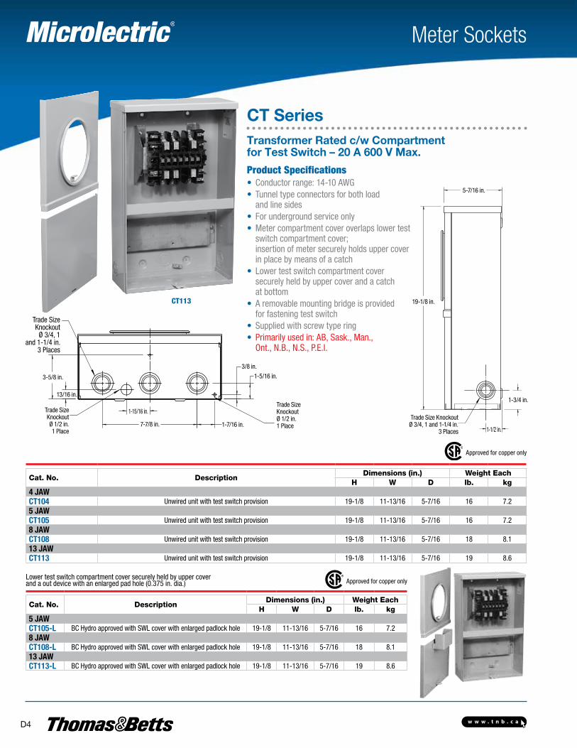
CT113
Meter Sockets
CT SeriesTransformer Rated c/w Compartment for Test Switch – 20 A 600 V Max.
Lower test switch compartment cover securely held by upper cover and a out device with an enlarged pad hole (0.375 in. dia.) Approved for copper only
Cat. No. DescriptionDimensions (in.) Weight Each
H W D lb. kg5 JAWCT105-L BC Hydro approved with SWL cover with enlarged padlock hole 19-1/8 11-13/16 5-7/16 16 7.28 JAWCT108-L BC Hydro approved with SWL cover with enlarged padlock hole 19-1/8 11-13/16 5-7/16 18 8.113 JAWCT113-L BC Hydro approved with SWL cover with enlarged padlock hole 19-1/8 11-13/16 5-7/16 19 8.6
Approved for copper only
Cat. No. DescriptionDimensions (in.) Weight Each
H W D lb. kg4 JAWCT104 Unwired unit with test switch provision 19-1/8 11-13/16 5-7/16 16 7.25 JAWCT105 Unwired unit with test switch provision 19-1/8 11-13/16 5-7/16 16 7.28 JAWCT108 Unwired unit with test switch provision 19-1/8 11-13/16 5-7/16 18 8.113 JAWCT113 Unwired unit with test switch provision 19-1/8 11-13/16 5-7/16 19 8.6
Trade SizeKnockout
Ø 3/4, 1 and 1-1/4 in.
3 Places
3-5/8 in.
13/16 in.
Trade Size Knockout Ø 1/2 in.1 Place
1-15/16 in.
7-7/8 in.
3/8 in.
1-7/16 in.
1-5/16 in.
Trade Size Knockout Ø 1/2 in.1 Place
19-1/8 in.
5-7/16 in.
1-3/4 in.
1-1/2 in.
Trade Size KnockoutØ 3/4, 1 and 1-1/4 in.
3 Places
Product Specifications• Conductor range: 14-10 AWG• Tunnel type connectors for both load
and line sides• For underground service only• Meter compartment cover overlaps lower test
switch compartment cover; insertion of meter securely holds upper cover in place by means of a catch
• Lower test switch compartment cover securely held by upper cover and a catch at bottom
• A removable mounting bridge is provided for fastening test switch
• Supplied with screw type ring• Primarily used in: AB, Sask., Man.,
Ont., N.B., N.S., P.E.I.
w w w . t n b . c a D5
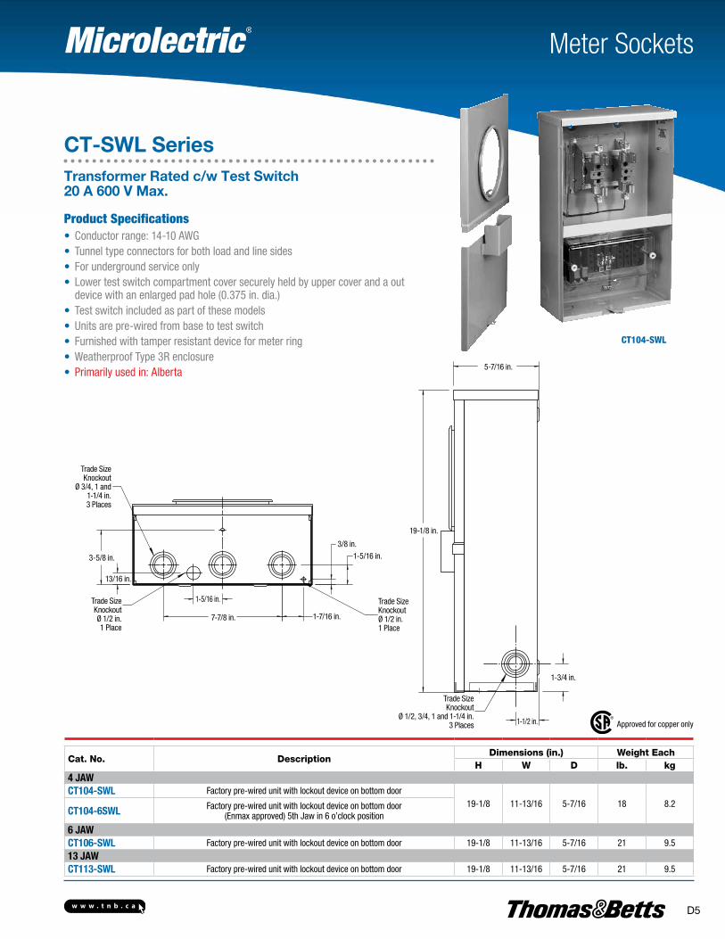
CT104-SWL
Meter Sockets
CT-SWL SeriesTransformer Rated c/w Test Switch 20 A 600 V Max.
Product Specifications• Conductor range: 14-10 AWG• Tunnel type connectors for both load and line sides• For underground service only• Lower test switch compartment cover securely held by upper cover and a out
device with an enlarged pad hole (0.375 in. dia.)• Test switch included as part of these models• Units are pre-wired from base to test switch• Furnished with tamper resistant device for meter ring• Weatherproof Type 3R enclosure• Primarily used in: Alberta
Approved for copper only
Cat. No. DescriptionDimensions (in.) Weight Each
H W D lb. kg4 JAWCT104-SWL Factory pre-wired unit with lockout device on bottom door
19-1/8 11-13/16 5-7/16 18 8.2CT104-6SWL Factory pre-wired unit with lockout device on bottom door
(Enmax approved) 5th Jaw in 6 o’clock position
6 JAWCT106-SWL Factory pre-wired unit with lockout device on bottom door 19-1/8 11-13/16 5-7/16 21 9.513 JAWCT113-SWL Factory pre-wired unit with lockout device on bottom door 19-1/8 11-13/16 5-7/16 21 9.5
Trade SizeKnockout
Ø 3/4, 1 and 1-1/4 in.3 Places
3-5/8 in.
13/16 in.
Trade Size Knockout Ø 1/2 in.1 Place
1-5/16 in.
7-7/8 in. 1-7/16 in.
3/8 in.
1-5/16 in.
Trade Size Knockout Ø 1/2 in.1 Place
19-1/8 in.
Trade SizeKnockout
Ø 1/2, 3/4, 1 and 1-1/4 in.3 Places 1-1/2 in.
1-3/4 in.
5-7/16 in.
w w w . t n b . c aD6
Meter Sockets
R3 SeriesRound Aluminum 100 A 600 V Max.
Product Specifications• Conductor range: 14-2 AWG• Aluminum tunnel type connectors for both load and line sides• Can be converted from vertical to horizontal mounting using same components• Supplied with screw type ring• Aluminum die cast socket• Weatherproof Type 3R enclosure• Primarily used in: B.C., Northern Ont.
Approved for copper only
Cat. No. DescriptionDimensions (in.) Weight EachDia. D lb. kg
4 JAWR3-1V 1 in. hub
7-1/8 3-1/8 2 0.9R3-1-1/4V 1-1/4 in. hub
R3-1-5V 1 in. hub - 5th jaw, standard capacity, 9 o’clock position
R3-1 1/4-5V 1-1/4 in. hub - 5th jaw, standard capacity, 9 o’clock position
2-7/8 in.
5-1/8 in.
2-1/8 in.
2-7/8 in.
1-1/8 in.
7-1/8 in.
w w w . t n b . c a D7
Meter Sockets
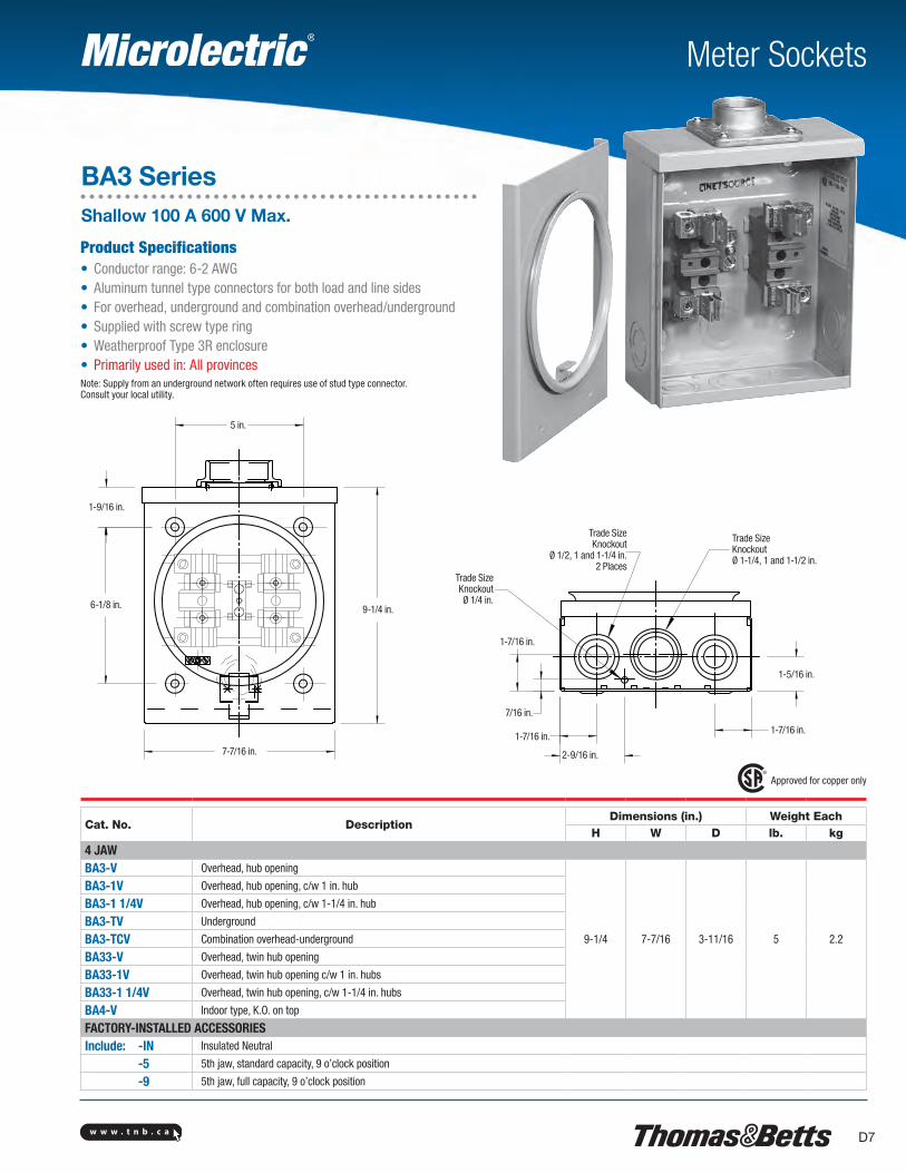
BA3 SeriesShallow 100 A 600 V Max.
Product Specifications• Conductor range: 6-2 AWG• Aluminum tunnel type connectors for both load and line sides• For overhead, underground and combination overhead/underground • Supplied with screw type ring• Weatherproof Type 3R enclosure• Primarily used in: All provincesNote: Supply from an underground network often requires use of stud type connector. Consult your local utility.
Approved for copper only
Cat. No. DescriptionDimensions (in.) Weight Each
H W D lb. kg
4 JAWBA3-V Overhead, hub opening
9-1/4 7-7/16 3-11/16 5 2.2
BA3-1V Overhead, hub opening, c/w 1 in. hub
BA3-1 1/4V Overhead, hub opening, c/w 1-1/4 in. hub
BA3-TV Underground
BA3-TCV Combination overhead-underground
BA33-V Overhead, twin hub opening
BA33-1V Overhead, twin hub opening c/w 1 in. hubs
BA33-1 1/4V Overhead, twin hub opening, c/w 1-1/4 in. hubs
BA4-V Indoor type, K.O. on top
FACTORY-INSTALLED ACCESSORIESInclude: -IN Insulated Neutral
-5 5th jaw, standard capacity, 9 o’clock position
-9 5th jaw, full capacity, 9 o’clock position
1-9/16 in.
5 in.
9-1/4 in.
7-7/16 in.
6-1/8 in.
Trade SizeKnockout
Ø 1/2, 1 and 1-1/4 in.2 Places
Trade SizeKnockoutØ 1-1/4, 1 and 1-1/2 in.
Trade Size Knockout Ø 1/4 in.
1-7/16 in.
7/16 in.
1-7/16 in.
2-9/16 in.
1-7/16 in.
1-5/16 in.
w w w . t n b . c aD8
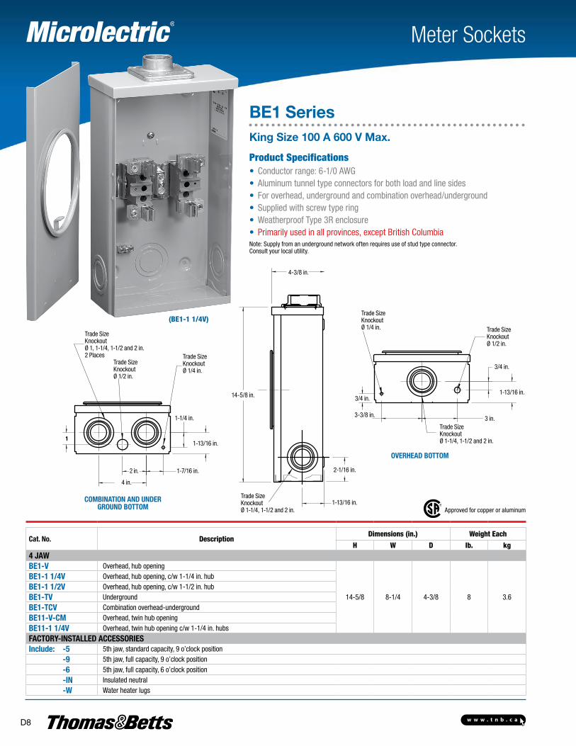
(BE1-1 1/4V)
Meter Sockets
BE1 SeriesKing Size 100 A 600 V Max.
Product Specifications• Conductor range: 6-1/0 AWG• Aluminum tunnel type connectors for both load and line sides• For overhead, underground and combination overhead/underground • Supplied with screw type ring• Weatherproof Type 3R enclosure• Primarily used in all provinces, except British ColumbiaNote: Supply from an underground network often requires use of stud type connector. Consult your local utility.
Approved for copper or aluminum
Cat. No. DescriptionDimensions (in.) Weight Each
H W D lb. kg4 JAWBE1-V Overhead, hub opening
14-5/8 8-1/4 4-3/8 8 3.6
BE1-1 1/4V Overhead, hub opening, c/w 1-1/4 in. hubBE1-1 1/2V Overhead, hub opening, c/w 1-1/2 in. hubBE1-TV UndergroundBE1-TCV Combination overhead-undergroundBE11-V-CM Overhead, twin hub openingBE11-1 1/4V Overhead, twin hub opening c/w 1-1/4 in. hubsFACTORY-INSTALLED ACCESSORIESInclude: -5 5th jaw, standard capacity, 9 o’clock position -9 5th jaw, full capacity, 9 o’clock position -6 5th jaw, full capacity, 6 o’clock position -IN Insulated neutral -W Water heater lugs
COMBINATION AND UNDER GROUND BOTTOM
OVERHEAD BOTTOM
4 in.
2 in. 1-7/16 in.
1-13/16 in.
1-1/4 in.
Trade Size Knockout Ø 1/4 in.
Trade Size Knockout Ø 1/2 in.
Trade SizeKnockoutØ 1, 1-1/4, 1-1/2 and 2 in.2 Places
4-3/8 in.
14-5/8 in.
2-1/16 in.
1-13/16 in.Trade SizeKnockoutØ 1-1/4, 1-1/2 and 2 in.
Trade Size Knockout Ø 1/4 in. Trade Size
Knockout Ø 1/2 in.
3/4 in.
1-13/16 in.3/4 in.
3-3/8 in.
Trade SizeKnockoutØ 1-1/4, 1-1/2 and 2 in.
3 in.
w w w . t n b . c a D9
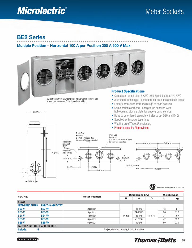
Meter Sockets
BE2 SeriesMultiple Position – Horizontal 100 A per Position 200 A 600 V Max.
Product Specifications• Conductor range: Line: 6 AWG-250 kcmil, Load: 6-1/0 AWG• Aluminum tunnel type connectors for both line and load sides• Factory prebussed from main lugs to each position• Combination overhead-underground supplied with
hub opening closure plate for underground service• Hubs to be ordered separately (refer to pp. D39 and D40)• Supplied with screw type rings• Weatherproof Type 3R enclosure• Primarily used in: All provinces
Approved for copper or aluminum
Cat. No. Meter PositionDimensions (in.) Weight Each
H W D lb. kg4 JAWLEFT-HAND ENTRY RIGHT-HAND ENTRYBE2-V BE2-VH 2 position
14-5/8
16-1/2
5-3/16
18 8.1BE3-V BE3-VH 3 position 24-13/16 26 11.8BE4-V BE4-VH 4 position 33-1/8 34 15.4BE5-V BE5-VH 5 position 41-7/16 42 19.0BE6-V BE6-VH 6 position 49-3/4 50 22.7FACTORY-INSTALLED ACCESSORIESInclude: -5 5th jaw, standard capacity, 9 o’clock position
NOTE: Supply from an underground network often requires useof stud type connector. Consult your local utility.
5-3/16 in.
14-5/8 in.
2-1/2 in.
2-1/4 in.
Trade SizeKnockoutØ 1-1/4, 1-1/2 and 2 in.(each side of the box separation)
Trade SizeKnockoutØ 1/22 Places(for each end of the bottom)
1-13/16 in.
1-1/16 in. 4-1/8 in.
8-5/16 in.
2-3/16 in.
Trade SizeKnockoutØ 1-1/4, 1-1/2, 2 and 2-1/2 in.(for every box separation)
1-1/16 in.4-1/16 in. 8-5/16 in.
8-5/16 in.8-3/16 in.
w w w . t n b . c aD10
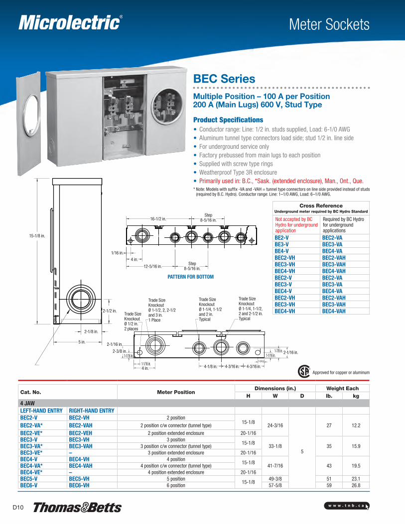
Meter Sockets
BEC SeriesMultiple Position – 100 A per Position 200 A (Main Lugs) 600 V, Stud Type
Product Specifications• Conductor range: Line: 1/2 in. studs supplied, Load: 6-1/0 AWG• Aluminum tunnel type connectors load side; stud 1/2 in. line side• For underground service only• Factory prebussed from main lugs to each position• Supplied with screw type rings• Weatherproof Type 3R enclosure• Primarily used in: B.C., *Sask. (extended enclosure), Man., Ont., Que.* Note: Models with suffix -VA and -VAH = tunnel type connectors on line side provided instead of studs
(required by B.C. Hydro). Conductor range: Line: 1–1/0 AWG, Load: 6–1/0 AWG.
Approved for copper or aluminum
Cat. No. Meter PositionDimensions (in.) Weight Each
H W D lb. kg4 JAWLEFT-HAND ENTRY RIGHT-HAND ENTRYBEC2-V BEC2-VH 2 position
15-1/824-3/16
5
27 12.2BEC2-VA* BEC2-VAH 2 position c/w connector (tunnel type)
BEC2-VE* BEC2-VEH 2 position extended enclosure 20-1/16BEC3-V BEC3-VH 3 position
15-1/833-1/8 35 15.9BEC3-VA* BEC3-VAH 3 position c/w connector (tunnel type)
BEC3-VE* – 3 position extended enclosure 20-1/16BEC4-V BEC4-VH 4 position
15-1/841-7/16 43 19.5BEC4-VA* BEC4-VAH 4 position c/w connector (tunnel type)
BEC4-VE* – 4 position extended enclosure 20-1/16BEC5-V BEC5-VH 5 position
15-1/849-3/8 51 23.1
BEC6-V BEC6-VH 6 position 57-5/8 59 26.8
PATTERN FOR BOTTOM
Cross Reference Underground meter required by BC Hydro Standard
Not accepted by BC Hydro for underground application
Required by BC Hydro for underground applications
BE2-V BEC2-VABE3-V BEC3-VABE4-V BEC4-VABEC2-VH BEC2-VAHBEC3-VH BEC3-VAHBEC4-VH BEC4-VAHBEC2-V BEC2-VABEC3-V BEC3-VABEC4-V BEC4-VABEC2-VH BEC2-VAHBEC3-VH BEC3-VAHBEC4-VH BEC4-VAH
15-1/8 in.
2-1/2 in.
2-1/8 in.
5 in.
16-1/2 in.Step
8-5/16 in.
1/16 in.4 in.
12-5/16 in.Step
8-5/16 in.
Trade Size Knockout Ø 1/2 in.2 places
Trade SizeKnockoutØ 1-1/2, 2, 2-1/2 and 3 in.1 Place
Trade SizeKnockoutØ 1-1/4, 1-1/2 and 2 in.Typical
Trade SizeKnockoutØ 1-1/4, 1-1/2, 2 and 2-1/2 in.Typical
2-3/8 in.1-1/16 in.
1-1/16 in.4 in. 4-1/8 in. 4-3/16 in. 4-3/16 in.
1-1/4 in.
1-1/16 in.1-7/8 in.
2-1/16 in.
2-1/16 in.
w w w . t n b . c a D11
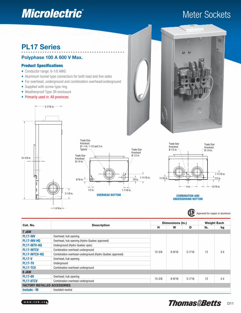
Meter Sockets
Approved for copper or aluminum
Cat. No. DescriptionDimensions (in.) Weight Each
H W D lb. kg7 JAWPL17-INV Overhead, hub opening
15-5/8 8-9/16 5-7/16 12 5.4
PL17-INV-HQ Overhead, hub opening (Hydro-Quebec approved)
PL17-INTV-HQ Underground (Hydro-Quebec spec)
PL17-INTCV Combination overhead-underground
PL17-INTCV-HQ Combination overhead-underground (Hydro-Quebec approved)
PL17-V Overhead, hub opening
PL17-TV Underground
PL17-TCV Combination overhead-underground
8 JAWPL17-8V Overhead, hub opening
15-5/8 8-9/16 5-7/16 12 5.4PL17-8TCV Combination overhead-underground
FACTORY INSTALLED ACCESSORIESInclude: -IN Insulated neutral
PL17 SeriesPolyphase 100 A 600 V Max.
Product Specifications• Conductor range: 6-1/0 AWG• Aluminum tunnel type connectors for both load and line sides• For overhead, underground and combination overhead/underground • Supplied with screw type ring• Weatherproof Type 3R enclosure• Primarily used in: All provinces
OVERHEAD BOTTOM COMBINATION AND UNDERGROUND BOTTOM
Trade SizeKnockoutØ 1-1/4, 1-1/2 and 2 in.Typical
1-3/16 in.
2-1/8 in.
15-5/8 in.
5-7/16 in.
Trade Size Knockout Ø 1/4 in.
9/16 in.
1/2 in. 1-1/16 in.
7/8 in.1-11/16 in.
Trade Size Knockout Ø 1/2 in.
Trade Size Knockout Ø 1/2 in.
Trade Size Knockout Ø 1/4 in.
11/16 in.
13/16 in.4 in.
1/2 in.
1-11/16 in.
w w w . t n b . c aD12
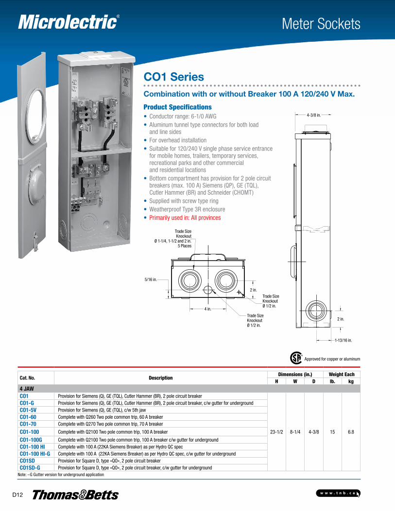
Meter Sockets
CO1 Series Combination with or without Breaker 100 A 120/240 V Max.
Product Specifications• Conductor range: 6-1/0 AWG• Aluminum tunnel type connectors for both load
and line sides• For overhead installation • Suitable for 120/240 V single phase service entrance
for mobile homes, trailers, temporary services, recreational parks and other commercial and residential locations
• Bottom compartment has provision for 2 pole circuit breakers (max. 100 A) Siemens (QP), GE (TQL), Cutler Hammer (BR) and Schneider (CHOMT)
• Supplied with screw type ring• Weatherproof Type 3R enclosure• Primarily used in: All provinces
Approved for copper or aluminum
Cat. No. DescriptionDimensions (in.) Weight Each
H W D lb. kg4 JAWCO1 Provision for Siemens (Q), GE (TQL), Cutler Hammer (BR), 2 pole circuit breaker
23-1/2 8-1/4 4-3/8 15 6.8
CO1-G Provision for Siemens (Q), GE (TQL), Cutler Hammer (BR), 2 pole circuit breaker, c/w gutter for undergroundCO1-5V Provision for Siemens (Q), GE (TQL), c/w 5th jawCO1-60 Complete with Q260 Two pole common trip, 60 A breakerCO1-70 Complete with Q270 Two pole common trip, 70 A breaker
CO1-100 Complete with Q2100 Two pole common trip, 100 A breaker
CO1-100G Complete with Q2100 Two pole common trip, 100 A breaker c/w gutter for undergroundCO1-100 HI Complete with 100 A (22KA Siemens Breaker) as per Hydro QC specCO1-100 HI-G Complete with 100 A (22KA Siemens Breaker) as per Hydro QC spec, c/w gutter for undergroundCO1SD Provision for Square D, type «QO», 2 pole circuit breakerCO1SD-G Provision for Square D, type «QO», 2 pole circuit breaker, c/w gutter for underground
Note: –G Gutter version for underground application
Trade SizeKnockout
Ø 1-1/4, 1-1/2 and 2 in.5 Places
5/16 in.
2 in.
4 in.
Trade Size Knockout Ø 1/2 in.
Trade Size Knockout Ø 1/2 in.
1-13/16 in.
2 in.
4-3/8 in.
w w w . t n b . c a D13
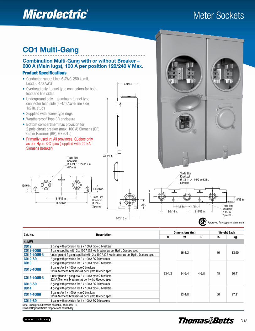
Meter Sockets
CO1 Multi-GangCombination Multi-Gang with or without Breaker – 200 A (Main lugs), 100 A per position 120/240 V Max.Product Specifications• Conductor range: Line: 6 AWG-250 kcmil,
Load: 6-1/0 AWG• Overhead only, tunnel type connectors for both
load and line sides• Underground only – aluminum tunnel type
connector load side (6–1/0 AWG) line side 1/2 in. studs
• Supplied with screw type rings• Weatherproof Type 3R enclosure• Bottom compartment has provision for
2 pole circuit breaker (max. 100 A) Siemens (QP), Cutler Hammer (BR), GE (QTL)
• Primarily used in: All provinces, Quebec only as per Hydro QC spec (supplied with 22 kA Siemens breaker)
Approved for copper or aluminum
Cat. No. DescriptionDimensions (in.) Weight Each
H W D lb. kg4 JAWCO12 2 gang with provision for 2 x 100 A type Q breakers
23-1/2
16-1/2
4-3/8
30 13.60CO12-100HI 2 gang supplied with 2 x 100 A (22 kA) breaker as per Hydro Quebec specCO12-100HI-U Underground 2 gang supplied with 2 x 100 A (22 kA) breaker as per Hydro Quebec specCO12-SD 2 gang with provision for 2 x 100 A SQ D breakersCO13 3 gang with provision for 3 x 100 A type Q breakers
24-3/4 45 20.41CO13-100HI 3 gang c/w 3 x 100 A type Q breakers
22 kA Siemens breakers as per Hydro Quebec spec
CO13-100HI-U Underground 3 gang c/w 3 x 100 A type Q breakers22 kA Siemens breakers as per Hydro Quebec spec
CO13-SD 3 gang with provision for 3 x 100 A SQ D breakersCO14 4 gang with provision for 4 x 100 A type Q breakers
33-1/8 60 27.21CO14-100HI 4 gang c/w 4 x 100 A type Q breakers22 kA Siemens breakers as per Hydro Quebec spec
CO14-SD 4 gang with provision for 4 x 100 A SQ D breakersNote: Underground version available, add suffix –UConsult Regional Sales for price and availability
1-13/16 in.
2 in.
23-1/2 in.
4-3/8 in.
Trade SizeKnockoutØ 1-1/4, 1-1/2 and 2 in.4 Places
15/16 in.
8-5/16 in.
14-1/16 in.
1-15/16 in.
Trade Size Knockout Ø 1/2 in.2 places
Trade SizeKnockoutØ 1/2, 1-1/4, 1-1/2 and 2 in.5 Places
4-1/8 in. 4-1/8 in.
8-5/16 in. 8-5/16 in.
1-15/16 in.15/16 in.
Trade Size Knockout Ø 1/2 in.2 places
w w w . t n b . c aD14
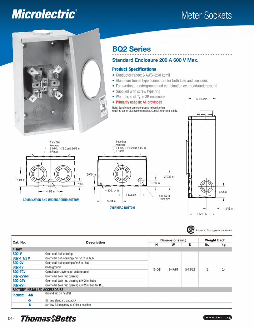
Meter Sockets
BQ2 SeriesStandard Enclosure 200 A 600 V Max.
Product Specifications• Conductor range: 6 AWG–250 kcmil• Aluminum tunnel type connectors for both load and line sides• For overhead, underground and combination overhead/underground • Supplied with screw type ring• Weatherproof Type 3R enclosure• Primarily used in: All provincesNote: Supply from an underground network oftenrequires use of stud type connector. Consult your local utility.
Approved for copper or aluminum
Cat. No. DescriptionDimensions (in.) Weight Each
H W D lb. kg4 JAWBQ2-V Overhead, hub opening
15-5/8 8-47/64 5-13/32 12 5.4
BQ2-1 1/2 V Overhead, hub opening c/w 1-1/2 in. hubBQ2-2V Overhead, hub opening c/w 2 in. hubBQ2-TV UndergroundBQ2-TCV Combination, overhead-undergroundBQ2-22VNH Overhead, twin hub openingBQ2-22V Overhead, twin hub opening c/w 2 in. hubsBQ2-2VR Overhead, twin hub opening c/w 2 in. hub for B.C.FACTORY INSTALLED ACCESSORIESInclude: -GN Ground lug on neutral
-5 5th jaw standard capacity -6 5th jaw full capacity, 6 o’clock position
5-13/32 in.
5-5/16 in.
1-13/16 in.
2-1/8 in.
29/64 in.
3-3/4 in.
3-17/64 in.
K.O. 1/4 in.
K.O. 1/2 in.Trade size
1-1/32 in.
2-7/32 in.
Trade SizeKnockoutØ 1-1/4, 1-1/2, 2 and 2-1/2 in.2 Places
7/8 in.
4-3/8 in.
2-1/4 in.
Trade SizeKnockoutØ 1-1/4, 1-1/2, 2 and 2-1/2 in.2 Places
OVERHEAD BOTTOM
COMBINATION AND UNDERGROUND BOTTOM
w w w . t n b . c a D15
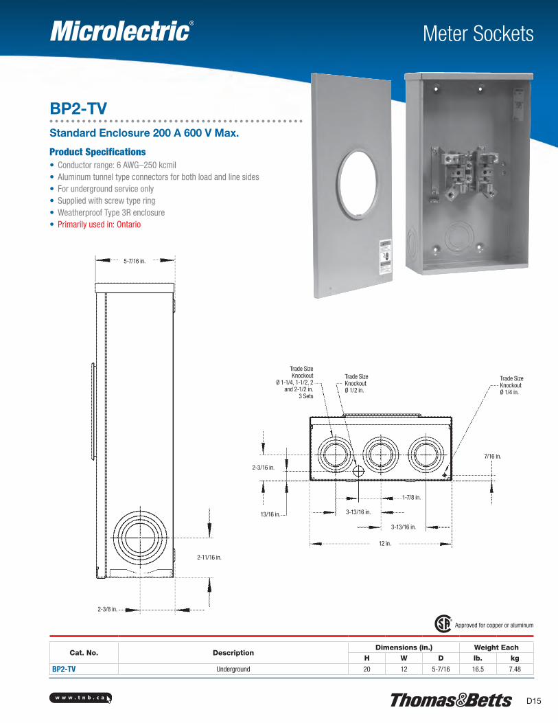
Meter Sockets
BP2-TVStandard Enclosure 200 A 600 V Max.
Product Specifications• Conductor range: 6 AWG–250 kcmil• Aluminum tunnel type connectors for both load and line sides• For underground service only • Supplied with screw type ring• Weatherproof Type 3R enclosure• Primarily used in: Ontario
Approved for copper or aluminum
Cat. No. DescriptionDimensions (in.) Weight Each
H W D lb. kg
BP2-TV Underground 20 12 5-7/16 16.5 7.48
2-3/16 in.
13/16 in.
Trade SizeKnockout
Ø 1-1/4, 1-1/2, 2 and 2-1/2 in.
3 Sets
Trade Size Knockout Ø 1/2 in.
Trade Size Knockout Ø 1/4 in.
7/16 in.
3-13/16 in.
1-7/8 in.
3-13/16 in.
12 in.
5-7/16 in.
2-11/16 in.
2-3/8 in.
w w w . t n b . c aD16
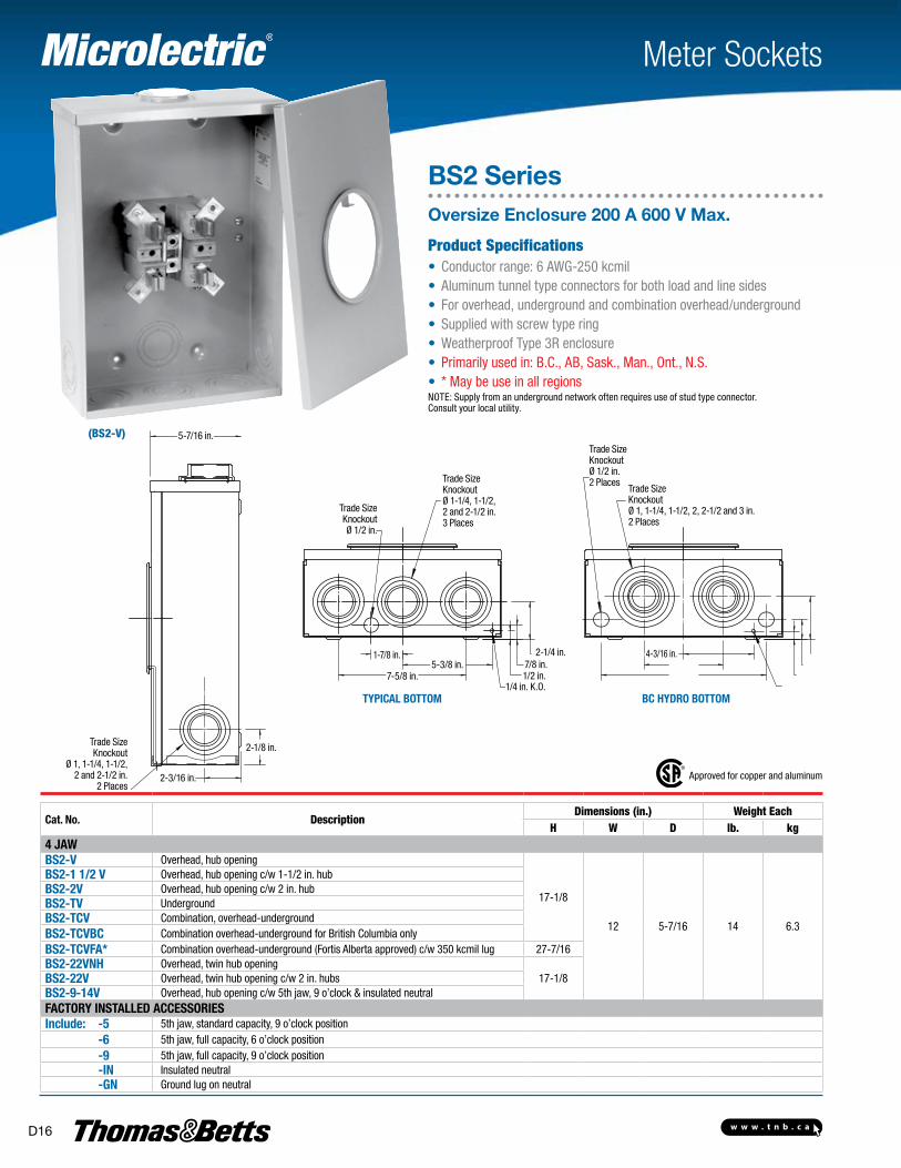
(BS2-V)
Approved for copper and aluminum
Cat. No. DescriptionDimensions (in.) Weight Each
H W D lb. kg4 JAWBS2-V Overhead, hub opening
17-1/8
12 5-7/16 14 6.3
BS2-1 1/2 V Overhead, hub opening c/w 1-1/2 in. hubBS2-2V Overhead, hub opening c/w 2 in. hubBS2-TV UndergroundBS2-TCV Combination, overhead-undergroundBS2-TCVBC Combination overhead-underground for British Columbia onlyBS2-TCVFA* Combination overhead-underground (Fortis Alberta approved) c/w 350 kcmil lug 27-7/16BS2-22VNH Overhead, twin hub opening
17-1/8BS2-22V Overhead, twin hub opening c/w 2 in. hubsBS2-9-14V Overhead, hub opening c/w 5th jaw, 9 o’clock & insulated neutralFACTORY INSTALLED ACCESSORIESInclude: -5 5th jaw, standard capacity, 9 o’clock position -6 5th jaw, full capacity, 6 o’clock position -9 5th jaw, full capacity, 9 o’clock position -IN Insulated neutral -GN Ground lug on neutral
Meter Sockets
BS2 SeriesOversize Enclosure 200 A 600 V Max.
Product Specifications• Conductor range: 6 AWG-250 kcmil• Aluminum tunnel type connectors for both load and line sides• For overhead, underground and combination overhead/underground • Supplied with screw type ring• Weatherproof Type 3R enclosure• Primarily used in: B.C., AB, Sask., Man., Ont., N.S.• * May be use in all regionsNOTE: Supply from an underground network often requires use of stud type connector. Consult your local utility.
TYpICAL BOTTOm BC HYDRO BOTTOm
5-7/16 in.
2-1/8 in.
2-3/16 in.
Trade SizeKnockout
Ø 1, 1-1/4, 1-1/2, 2 and 2-1/2 in.
2 Places
Trade Size Knockout Ø 1/2 in.
Trade SizeKnockoutØ 1-1/4, 1-1/2, 2 and 2-1/2 in.3 Places
1-7/8 in.
7-5/8 in.5-3/8 in.
1/4 in. K.O.1/2 in.7/8 in.
2-1/4 in.
Trade Size Knockout Ø 1/2 in.2 Places
Trade SizeKnockoutØ 1, 1-1/4, 1-1/2, 2, 2-1/2 and 3 in.2 Places
4-3/16 in.
w w w . t n b . c a D17
Meter Sockets
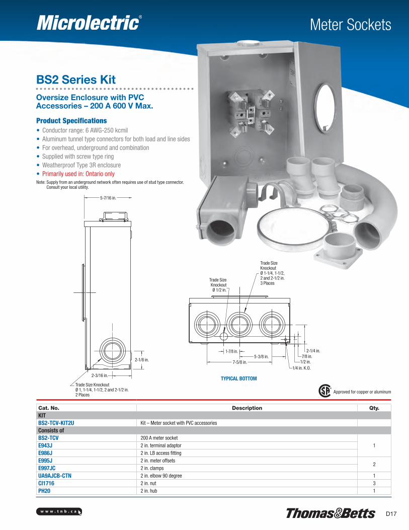
BS2 Series KitOversize Enclosure with PVC Accessories – 200 A 600 V Max.
Product Specifications• Conductor range: 6 AWG-250 kcmil• Aluminum tunnel type connectors for both load and line sides• For overhead, underground and combination • Supplied with screw type ring• Weatherproof Type 3R enclosure• Primarily used in: Ontario onlyNote: Supply from an underground network often requires use of stud type connector.
Consult your local utility.
Approved for copper or aluminum
Cat. No. Description Qty.KITBS2-TCV-KIT2U Kit – Meter socket with PVC accessories
Consists ofBS2-TCV 200 A meter socket
1E943J 2 in. terminal adaptor
E986J 2 in. LB access fitting
E995J 2 in. meter offsets2
E997JC 2 in. clamps
UA9AJCB-CTN 2 in. elbow 90 degree 1
CI1716 2 in. nut 3
PH20 2 in. hub 1
TYPICAL BOTTOM
5-7/16 in.
2-1/8 in.
2-3/16 in.
Trade Size KnockoutØ 1, 1-1/4, 1-1/2, 2 and 2-1/2 in.2 Places
Trade Size Knockout Ø 1/2 in.
Trade SizeKnockoutØ 1-1/4, 1-1/2, 2 and 2-1/2 in.3 Places
1-7/8 in.
7-5/8 in.5-3/8 in.
1/4 in. K.O.1/2 in.7/8 in.
2-1/4 in.
w w w . t n b . c aD18
Meter Sockets
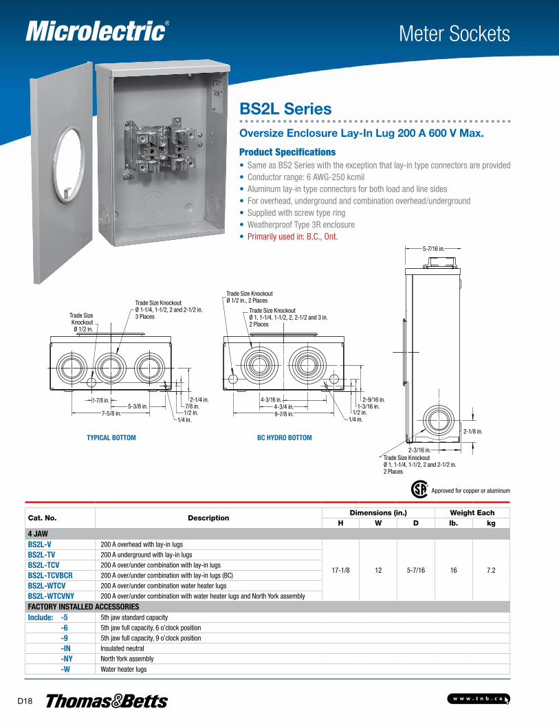
BS2L SeriesOversize Enclosure Lay-In Lug 200 A 600 V Max.
Product Specifications• Same as BS2 Series with the exception that lay-in type connectors are provided• Conductor range: 6 AWG-250 kcmil• Aluminum lay-in type connectors for both load and line sides• For overhead, underground and combination overhead/underground • Supplied with screw type ring• Weatherproof Type 3R enclosure• Primarily used in: B.C., Ont.
Approved for copper or aluminum
Cat. No. DescriptionDimensions (in.) Weight Each
H W D lb. kg
4 JAWBS2L-V 200 A overhead with lay-in lugs
17-1/8 12 5-7/16 16 7.2
BS2L-TV 200 A underground with lay-in lugs
BS2L-TCV 200 A over/under combination with lay-in lugs
BS2L-TCVBCR 200 A over/under combination with lay-in lugs (BC)
BS2L-WTCV 200 A over/under combination water heater lugs
BS2L-WTCVNY 200 A over/under combination with water heater lugs and North York assembly
FACTORY INSTALLED ACCESSORIESInclude: -5 5th jaw standard capacity
-6 5th jaw full capacity, 6 o’clock position
-9 5th jaw full capacity, 9 o’clock position
-IN Insulated neutral
-NY North York assembly
-W Water heater lugs
TYpICAL BOTTOm BC HYDRO BOTTOm
5-7/16 in.
2-1/8 in.
2-3/16 in.Trade Size KnockoutØ 1, 1-1/4, 1-1/2, 2 and 2-1/2 in.2 Places
Trade Size Knockout Ø 1/2 in.
Trade Size KnockoutØ 1-1/4, 1-1/2, 2 and 2-1/2 in.3 Places
Trade Size KnockoutØ 1, 1-1/4, 1-1/2, 2, 2-1/2 and 3 in.2 Places
Trade Size KnockoutØ 1/2 in., 2 Places
1-7/8 in.
7-5/8 in.5-3/8 in.
1/4 in. 1/4 in.1/2 in. 1/2 in.7/8 in.
2-1/4 in.1-3/16 in.
2-9/16 in.4-3/4 in.9-7/8 in.
4-3/16 in.
w w w . t n b . c a D19
Meter Sockets
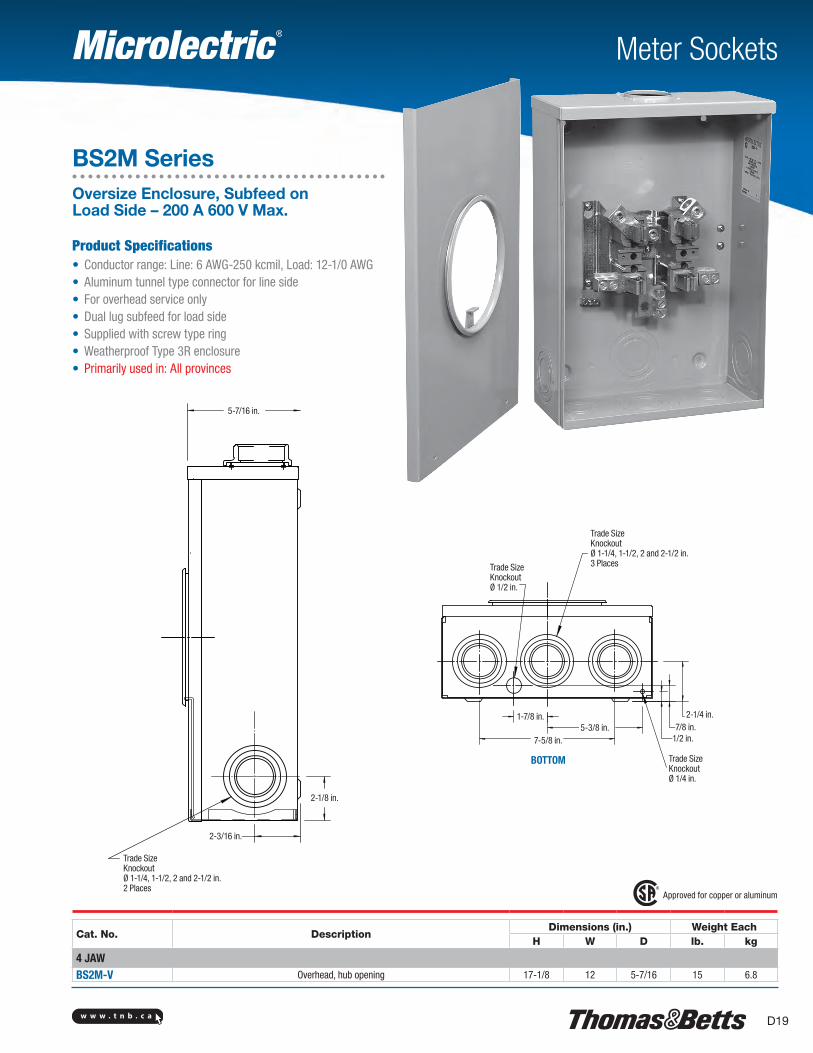
BS2M SeriesOversize Enclosure, Subfeed on Load Side – 200 A 600 V Max.
Product Specifications• Conductor range: Line: 6 AWG-250 kcmil, Load: 12-1/0 AWG• Aluminum tunnel type connector for line side• For overhead service only• Dual lug subfeed for load side• Supplied with screw type ring• Weatherproof Type 3R enclosure• Primarily used in: All provinces
Approved for copper or aluminum
Cat. No. DescriptionDimensions (in.) Weight Each
H W D lb. kg
4 JAWBS2M-V Overhead, hub opening 17-1/8 12 5-7/16 15 6.8
BOTTOM
5-7/16 in.
2-1/8 in.
2-3/16 in.
Trade SizeKnockoutØ 1-1/4, 1-1/2, 2 and 2-1/2 in.2 Places
Trade SizeKnockoutØ 1-1/4, 1-1/2, 2 and 2-1/2 in.3 PlacesTrade Size
Knockout Ø 1/2 in.
1-7/8 in.
7-5/8 in.5-3/8 in.
Trade Size Knockout Ø 1/4 in.
1/2 in.7/8 in.
2-1/4 in.
w w w . t n b . c aD20
Meter Sockets
Approved for copper or aluminum
Cat. No. DescriptionDimensions (in.) Weight Each
H W D lb. kg
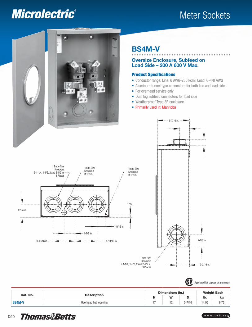
BS4M-V Overhead hub opening 17 12 5-7/16 14.95 6.75
BS4M-VOversize Enclosure, Subfeed on Load Side – 200 A 600 V Max.
Product Specifications• Conductor range: Line: 6 AWG-250 kcmil Load: 6-4/0 AWG• Aluminum tunnel type connectors for both line and load sides• For overhead service only• Dual lug subfeed connectors for load side• Weatherproof Type 3R enclosure• Primarily used in: Manitoba
5-7/16 in.
2-1/8 in.
2-3/16 in.
Trade SizeKnockout
Ø 1-1/4, 1-1/2, 2 and 2-1/2 in.3 Places
Trade SizeKnockout
Ø 1-1/4, 1-1/2, 2 and 2-1/2 in.3 Places
Trade Size Knockout Ø 1/2 in.
Trade Size Knockout Ø 1/2 in.
2-1/4 in.
1/2 in.
1-9/16 in.
3-13/16 in.3-13/16 in.
1-7/8 in.
w w w . t n b . c a D21
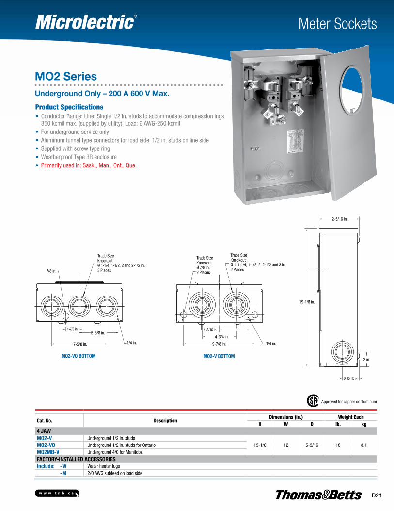
Meter Sockets
MO2 SeriesUnderground Only – 200 A 600 V Max.
Product Specifications• Conductor Range: Line: Single 1/2 in. studs to accommodate compression lugs
350 kcmil max. (supplied by utility), Load: 6 AWG-250 kcmil• For underground service only• Aluminum tunnel type connectors for load side, 1/2 in. studs on line side• Supplied with screw type ring• Weatherproof Type 3R enclosure• Primarily used in: Sask., Man., Ont., Que.
Approved for copper or aluminum
Cat. No. DescriptionDimensions (in.) Weight Each
H W D lb. kg4 JAWMO2-V Underground 1/2 in. studs
19-1/8 12 5-9/16 18 8.1MO2-VO Underground 1/2 in. studs for OntarioMO2MB-V Underground 4/0 for ManitobaFACTORY-INSTALLED ACCESSORIESInclude: -W Water heater lugs -M 2/0 AWG subfeed on load side
MO2-V BOTTOMMO2-VO BOTTOM
7-5/8 in. 1/4 in.
5-3/8 in.1-7/8 in.
7/8 in.
Trade SizeKnockoutØ 1-1/4, 1-1/2, 2 and 2-1/2 in.3 Places
Trade SizeKnockoutØ 7/8 in.2 Places
Trade SizeKnockoutØ 1, 1-1/4, 1-1/2, 2, 2-1/2 and 3 in.2 Places
1/4 in.9-7/8 in.
4-3/4 in.
4-3/16 in.
2-5/16 in.
19-1/8 in.
2-5/16 in.
2 in.
w w w . t n b . c aD22
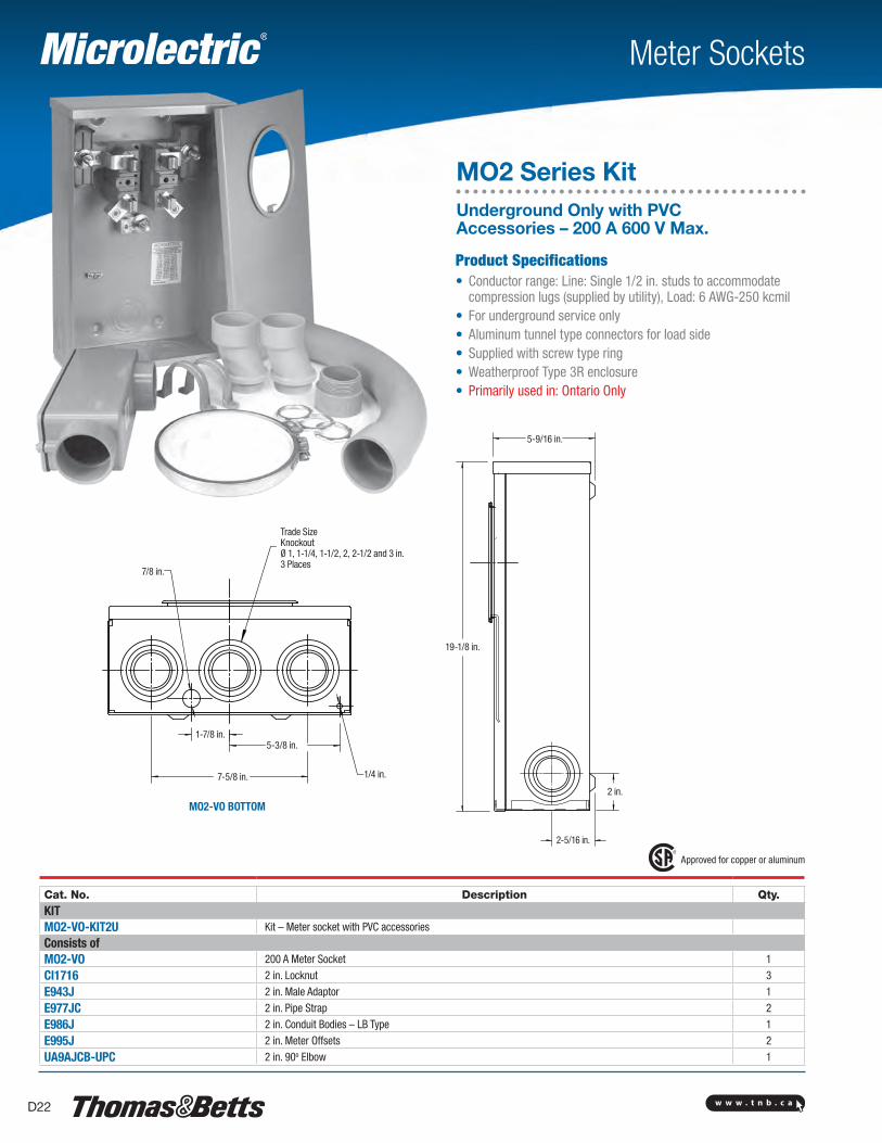
Meter Sockets
MO2 Series KitUnderground Only with PVC Accessories – 200 A 600 V Max.
Product Specifications• Conductor range: Line: Single 1/2 in. studs to accommodate
compression lugs (supplied by utility), Load: 6 AWG-250 kcmil • For underground service only• Aluminum tunnel type connectors for load side• Supplied with screw type ring• Weatherproof Type 3R enclosure• Primarily used in: Ontario Only
Approved for copper or aluminum
Cat. No. Description Qty.KITMO2-VO-KIT2U Kit – Meter socket with PVC accessories
Consists ofMO2-VO 200 A Meter Socket 1
CI1716 2 in. Locknut 3
E943J 2 in. Male Adaptor 1
E977JC 2 in. Pipe Strap 2
E986J 2 in. Conduit Bodies – LB Type 1
E995J 2 in. Meter Offsets 2
UA9AJCB-UPC 2 in. 90o Elbow 1
MO2-VO BOTTOM
7/8 in.
Trade SizeKnockoutØ 1, 1-1/4, 1-1/2, 2, 2-1/2 and 3 in.3 Places
1/4 in.7-5/8 in.
5-3/8 in.1-7/8 in.
5-9/16 in.
19-1/8 in.
2 in.
2-5/16 in.

w w w . t n b . c a D23
Meter Sockets
MO2 Series KitUnderground Only with PVC Accessories – 200 A 600 V Max.
Product Specifications• Conductor range: Line: Single 1/2 in. studs to accommodate
compression lugs (supplied by utility), Load: 6 AWG-250 kcmil• For underground service only• Aluminum tunnel type connectors for load side,
1/2 in. studs on line side• Supplied with screw type ring• Weatherproof Type 3R enclosure• Primarily used in: Quebec Only
Approved for copper or aluminum
Cat. No. Description Qty.KITMO2-V-KIT1-1/4U Meter socket with PVC accessories
Consists ofMO2-V 200 A Meter Socket
1CE942RL 3 in. PVC/DB2 Adaptor
CI1710 1-1/4 in. nut 2
CI1724 3 in. nut1
CI-DUCT-1 Duct Seal
E943G 1-1/4 in. Male Adaptor 2
E943L 3 in. Male Adaptor
1
E945L 3 in. Expansion Fitting
E977GC 1-1/4 in. Pipe Strap
E977LC-CAR 3 in. Pipe Strap
E986G 1-1/4 in. Conduit Bodies – LB Type
UA9AGCB-UPC 1-1/4 in. 90o Elbow
Cat. No. Description Qty.KITMO2-V-KIT2U Meter socket with PVC accessories
Consists ofMO2-V 200 A Meter Socket
1CE942RL 3 in. PVC/DB2 Adaptor
CI1716 2 in. nut 2
CI1724 3 in. nut1
CI-DUCT-1 Duct Seal
E943J 2 in. Male Adaptor 2
E943L 3 in. Male Adaptor
1
E945L 3 in. Expansion Fitting
E977JC 2 in. Pipe Strap
E977LC-CAR 3 in. Pipe Strap
E986J 2 in. Conduit Bodies – LB Type
UA9AJCB-UPC 2 in. 90o Elbow
MO2-V BOTTOM
5-9/16 in.
19-1/8 in.
2 in.
2-5/16 in.
Trade Size Knockout Ø 7/8 in.2 places
9-7/8 in. 1/4 in.
4-3/4 in.
4-3/16 in.
Trade SizeKnockoutØ 1, 1-1/4, 1-1/2, 2, 2-1/2 and 3 in.2 Places
w w w . t n b . c aD24
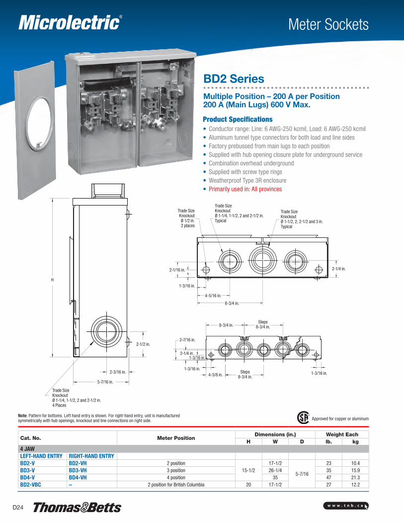
Meter Sockets
BD2 SeriesMultiple Position – 200 A per Position 200 A (Main Lugs) 600 V Max.
Product Specifications• Conductor range: Line: 6 AWG-250 kcmil, Load: 6 AWG-250 kcmil• Aluminum tunnel type connectors for both load and line sides• Factory prebussed from main lugs to each position• Supplied with hub opening closure plate for underground service• Combination overhead underground• Supplied with screw type rings• Weatherproof Type 3R enclosure• Primarily used in: All provinces
Approved for copper or aluminum
Cat. No. Meter PositionDimensions (in.) Weight Each
H W D lb. kg4 JAWLEFT-HAND ENTRY RIGHT-HAND ENTRYBD2-V BD2-VH 2 position
15-1/217-1/2
5-7/16
23 10.4BD3-V BD3-VH 3 position 26-1/4 35 15.9BD4-V BD4-VH 4 position 35 47 21.3BD2-VBC – 2 position for British Columbia 20 17-1/2 27 12.2
Note: Pattern for bottoms. Left hand entry is shown. For right-hand entry, unit is manufactured symmetrically with hub openings, knockout and line connections on right side.
2-1/2 in.
H
2-3/16 in.
5-7/16 in.
Trade SizeKnockoutØ 1-1/4, 1-1/2, 2 and 2-1/2 in.4 Places
2-1/16 in.
1-3/16 in.
4-5/16 in.
8-3/4 in.
2-1/4 in.
Trade SizeKnockoutØ 1-1/2, 2, 2-1/2 and 3 in.Typical
Trade SizeKnockoutØ 1-1/4, 1-1/2, 2 and 2-1/2 in.Typical
Trade Size Knockout Ø 1/2 in.2 places
8-3/4 in.Steps
8-3/4 in.
2-7/16 in.
2-1/4 in.1-3/16 in.
1-3/16 in.4-3/8 in.
Steps 8-3/4 in.
1-3/16 in.
w w w . t n b . c a D25
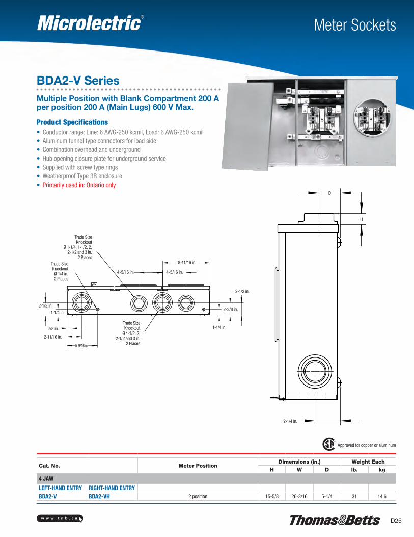
Meter Sockets
Product Specifications• Conductor range: Line: 6 AWG-250 kcmil, Load: 6 AWG-250 kcmil• Aluminum tunnel type connectors for load side• Combination overhead and underground• Hub opening closure plate for underground service• Supplied with screw type rings• Weatherproof Type 3R enclosure• Primarily used in: Ontario only
Approved for copper or aluminum
Cat. No. Meter PositionDimensions (in.) Weight Each
H W D lb. kg
4 JAW
LEFT-HAND ENTRY RIGHT-HAND ENTRYBDA2-V BDA2-VH 2 position 15-5/8 26-3/16 5-1/4 31 14.6
BDA2-V SeriesMultiple Position with Blank Compartment 200 A per position 200 A (Main Lugs) 600 V Max.
Trade SizeKnockout
Ø 1-1/4, 1-1/2, 2, 2-1/2 and 3 in.
2 PlacesTrade Size Knockout Ø 1/4 in.2 Places
4-5/16 in. 4-5/16 in.
8-11/16 in.
2-1/2 in.
2-3/8 in.
1-1/4 in.Trade SizeKnockout
Ø 1-1/2, 2, 2-1/2 and 3 in.
2 Places5-9/16 in.
2-11/16 in.
7/8 in.
1-1/4 in.2-1/2 in.
2-1/4 in.
H
D
w w w . t n b . c aD26
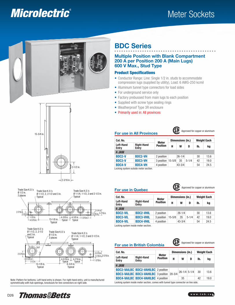
Locking system outside meter section.
Meter Sockets
BDC SeriesMultiple Position with Blank Compartment 200 A per Position 200 A (Main Lugs) 600 V Max., Stud TypeProduct Specifications• Conductor Range: Line: Single 1/2 in. studs to accommodate
compression lugs (supplied by utility), Load: 6 AWG-250 kcmil• Aluminum tunnel type connectors for load sides• For underground service only• Factory prebussed from main lugs to each position• Supplied with screw type sealing rings• Weatherproof Type 3R enclosure• Primarily used in: All provinces
For use in British Colombia Approved for copper or aluminum
Cat. No.Meter
Position
Dimensions (in.) Weight Each
Left-Hand Entry
Right-Hand Entry H W D lb. kg
4 JAWBDC2-VAILBC BDC2-VAHILBC 2 position
20-3/426-1/4 5-1/4 30 13.6
BDC3-VAILBC BDC3-VAHILBC 3 positionBDC4-VAILBC BDC4-VAHILBC 4 position 35 42 19.0
Locking system inside meter section, comes with tunnel type connector on line side.Note: Pattern for bottoms. Left hand entry is shown. For right-hand entry, unit is manufactured symmetrically with hub openings, knockouts for line connectors on right side.
For use in All Provinces Approved for copper or aluminum
Cat. No.Meter
Position
Dimensions (in.) Weight EachLeft-Hand Entry
Right-Hand Entry H W D lb. kg
4 JAWBDC2-V BDC2-VH 2 position
15-5/826-1/4
5-1/430 13.6
BDC3-V BDC3-VH 3 position 35 42 19.0BDC4-V BDC4-VH 4 position 43-3/4 54 24.5
For use in Quebec Approved for copper or aluminum
Cat. No.Meter
Position
Dimensions (in.) Weight EachLeft-Hand Entry
Right-Hand Entry H W D lb. kg
4 JAWBDC2-VIL BDC2-VHIL 2 position
15-5/826-1/4
5-1/430 13.6
BDC3-VIL BDC3-VHIL 3 position 35 42 19.0BDC4-VIL BDC4-VHIL 4 position 43-3/4 54 24.5
Locking system inside meter section.
15-5/8 in.
2-1/2 in.
2-3/16 in.
Trade Size K.O.’s Ø 1/2 in.2 places
Trade Size K.O.’s Ø 1-1/2, 2, 2-1/2 and 3 in.Typical
Trade Size K.O.’s Ø 1-1/2, 2, 2-1/2 and 3 in.Typical
Trade Size K.O.’s Ø 1-1/4, 1-1/2, 2 and 2-1/2 in.Typical
Trade Size K.O.’s Ø 1-1/4, 1-1/2, 2 and 2-1/2 in.Typical
2-7/16 in.
2-5/16 in.
1-9/16 in.
5-1/2 in.
1-1/8 in.
2-5/8 in.
4-5/16 in. 13-1/8 in.Typical
8-3/4 in.Typical
13-1/8 in.Typical
4-3/8 in.Typical
4-5/16 in.Typical
4-3/8 in.Typical
4-7/16 in.Typical
1-3/16 in.
1-3/16 in.
1-3/16 in.
1-1/16 in.
2-7/16 in.
2-5/16 in.
2-1/4 in.
2-3/16 in.
Trade Size K.O.’s Ø 1/2 in.2 places
w w w . t n b . c a D27
8-3/4
8-3/4
8-3/4
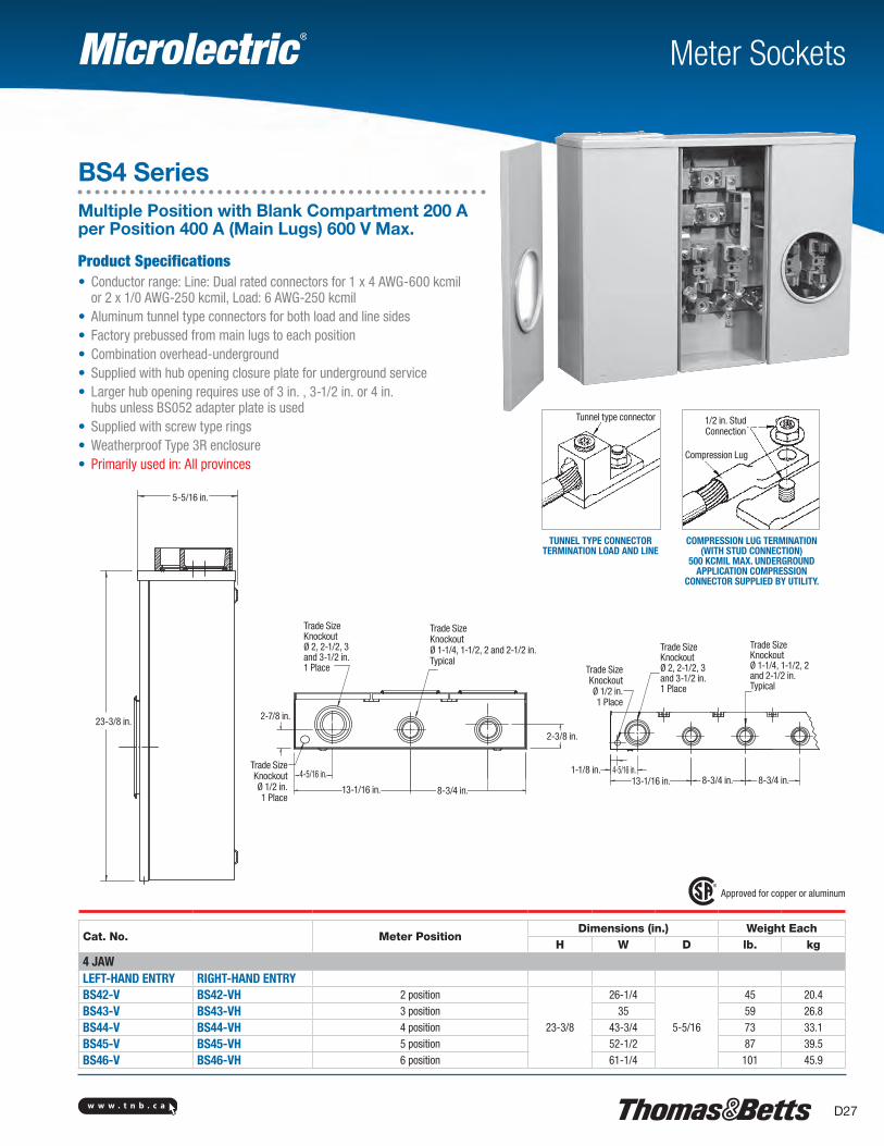
Meter Sockets
TUNNEL TYPE CONNECTOR TERMINATION LOAD AND LINE
COMPRESSION LUG TERMINATION (WITH STUD CONNECTION)
500 KCMIL MAX. UNDERGROUND APPLICATION COMPRESSION
CONNECTOR SUPPLIED BY UTILITY.
Approved for copper or aluminum
Cat. No. Meter PositionDimensions (in.) Weight Each
H W D lb. kg
4 JAWLEFT-HAND ENTRY RIGHT-HAND ENTRYBS42-V BS42-VH 2 position
23-3/8
26-1/4
5-5/16
45 20.4
BS43-V BS43-VH 3 position 35 59 26.8
BS44-V BS44-VH 4 position 43-3/4 73 33.1
BS45-V BS45-VH 5 position 52-1/2 87 39.5
BS46-V BS46-VH 6 position 61-1/4 101 45.9
BS4 SeriesMultiple Position with Blank Compartment 200 A per Position 400 A (Main Lugs) 600 V Max.
Product Specifications• Conductor range: Line: Dual rated connectors for 1 x 4 AWG-600 kcmil
or 2 x 1/0 AWG-250 kcmil, Load: 6 AWG-250 kcmil• Aluminum tunnel type connectors for both load and line sides• Factory prebussed from main lugs to each position• Combination overhead-underground• Supplied with hub opening closure plate for underground service • Larger hub opening requires use of 3 in. , 3-1/2 in. or 4 in.
hubs unless BS052 adapter plate is used• Supplied with screw type rings• Weatherproof Type 3R enclosure• Primarily used in: All provinces
Tunnel type connector
Compression Lug
1/2 in. Stud Connection
5-5/16 in.
23-3/8 in.
Trade SizeKnockoutØ 2, 2-1/2, 3 and 3-1/2 in.1 Place
Trade SizeKnockoutØ 1-1/4, 1-1/2, 2 and 2-1/2 in.Typical
2-3/8 in.
8-3/4 in.13-1/16 in.
4-5/16 in.Trade Size Knockout Ø 1/2 in.1 Place
2-7/8 in.
Trade Size Knockout Ø 1/2 in.1 Place
Trade SizeKnockoutØ 2, 2-1/2, 3 and 3-1/2 in.1 Place
Trade SizeKnockoutØ 1-1/4, 1-1/2, 2 and 2-1/2 in.Typical
1-1/8 in. 4-5/16 in.13-1/16 in. 8-3/4 in. 8-3/4 in.
w w w . t n b . c aD28
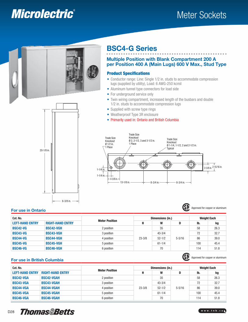
Meter Sockets
BSC4-G SeriesMultiple Position with Blank Compartment 200 A per Position 400 A (Main Lugs) 600 V Max., Stud Type
Product Specifications• Conductor range: Line: Single 1/2 in. studs to accommodate compression
lugs (supplied by utility), Load: 6 AWG-250 kcmil• Aluminum tunnel type connectors for load side• For underground service only• Twin wiring compartment, increased length of the busbars and double
1/2 in. studs to accommodate compression lugs• Supplied with screw type rings• Weatherproof Type 3R enclosure• Primarily used in: Ontario and British Columbia
For use in Ontario Approved for copper or aluminum
Cat. No.Meter Position
Dimensions (in.) Weight Each
LEFT-HAND ENTRY RIGHT-HAND ENTRY H W D lb. kg
BSC42-VG BSC42-VGH 2 position
23-3/8
35
5-5/16
58 26.3
BSC43-VG BSC43-VGH 3 position 43-3/4 72 32.7
BSC44-VG BSC44-VGH 4 position 52-1/2 86 39.0
BSC45-VG BSC45-VGH 5 position 61-1/4 100 45.4
BSC46-VG BSC46-VGH 6 position 70 114 51.8
For use in British Columbia Approved for copper or aluminum
Cat. No.Meter Position
Dimensions (in.) Weight Each
LEFT-HAND ENTRY RIGHT-HAND ENTRY H W D lb. kg
BSC42-VGA BSC42-VGAH 2 position
23-3/8
35
5-5/16
58 26.3
BSC43-VGA BSC43-VGAH 3 position 43-3/4 72 32.7
BSC44-VGA BSC44-VGAH 4 position 52-1/2 86 39.0
BSC45-VGA BSC45-VGAH 5 position 61-1/4 100 45.4
BSC46-VGA BSC46-VGAH 6 position 70 114 51.8
20-1/8 in.
6-3/8 in.
1-1/4 in.
1-1/4 in.4-3/8 in.
13-1/8 in. 8-3/4 in. 8-3/4 in.
2-3/8 in. 2-15/16 in.
Trade Size Knockout Ø 1/2 in.1 Place
Trade SizeKnockoutØ 2, 2-1/2, 3 and 3-1/2 in.1 Place
Trade SizeKnockoutØ 1-1/4, 1-1/2, 2 and 2-1/2 in.Typical
w w w . t n b . c a D29
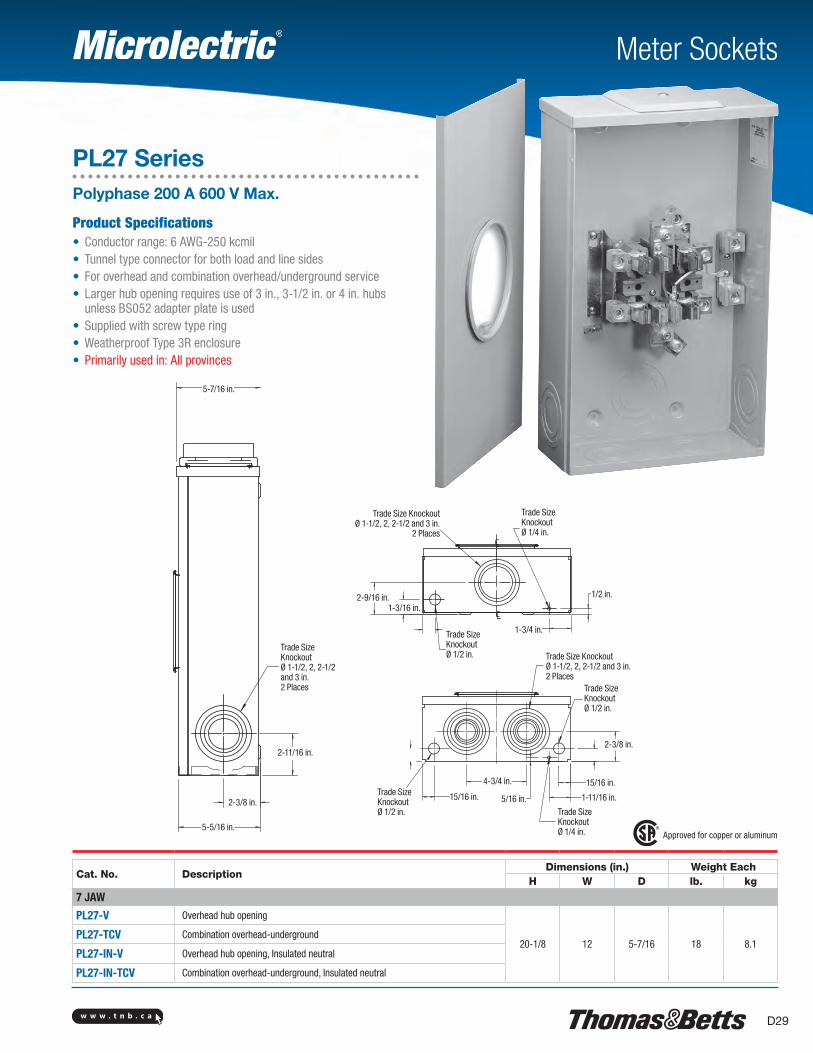
Meter Sockets
PL27 SeriesPolyphase 200 A 600 V Max.
Product Specifications• Conductor range: 6 AWG-250 kcmil• Tunnel type connector for both load and line sides• For overhead and combination overhead/underground service • Larger hub opening requires use of 3 in., 3-1/2 in. or 4 in. hubs
unless BS052 adapter plate is used• Supplied with screw type ring• Weatherproof Type 3R enclosure• Primarily used in: All provinces
Approved for copper or aluminum
Cat. No. DescriptionDimensions (in.) Weight Each
H W D lb. kg
7 JAW
PL27-V Overhead hub opening
20-1/8 12 5-7/16 18 8.1PL27-TCV Combination overhead-underground
PL27-IN-V Overhead hub opening, Insulated neutral
PL27-IN-TCV Combination overhead-underground, Insulated neutral
5-7/16 in.
Trade SizeKnockoutØ 1-1/2, 2, 2-1/2 and 3 in.2 Places
2-11/16 in.
2-3/8 in.
5-5/16 in.
Trade Size KnockoutØ 1-1/2, 2, 2-1/2 and 3 in.
2 Places
Trade Size Knockout Ø 1/4 in.
2-9/16 in.1-3/16 in.
Trade Size Knockout Ø 1/2 in.
1-3/4 in.
1/2 in.
Trade Size KnockoutØ 1-1/2, 2, 2-1/2 and 3 in.2 Places
Trade Size Knockout Ø 1/2 in.
2-3/8 in.
15/16 in.
1-11/16 in.
Trade Size Knockout Ø 1/4 in.
5/16 in.
4-3/4 in.
15/16 in.Trade Size Knockout Ø 1/2 in.
w w w . t n b . c aD30
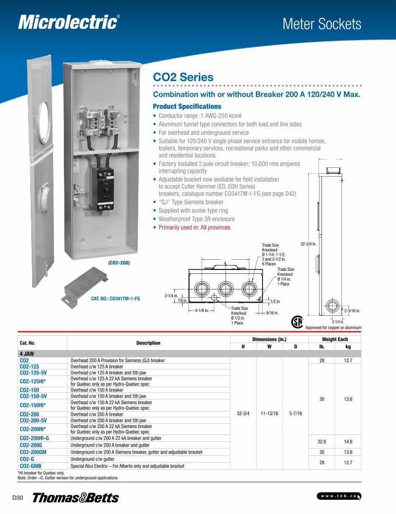
(CO2-200)
Meter Sockets
CO2 SeriesCombination with or without Breaker 200 A 120/240 V Max.
Cat. No.: Co3417M-1-FG
Approved for copper or aluminum
Cat. No. DescriptionDimensions (in.) Weight Each
H W D lb. kg4 JaWCo2 Overhead 200 A Provision for Siemens (QJ) breaker
32-3/4 11-13/16 5-7/16
28 12.7Co2-125 Overhead c/w 125 A breaker
30 13.6
Co2-125-5V Overhead c/w 125 A breaker and 5th jaw
Co2-125HI* Overhead c/w 125 A 22 kA Siemens breaker for Quebec only as per Hydro-Quebec spec
Co2-150 Overhead c/w 150 A breakerCo2-150-5V Overhead c/w 150 A breaker and 5th jaw
Co2-150HI* Overhead c/w 150 A 22 kA Siemens breakerfor Quebec only as per Hydro-Quebec spec
Co2-200 Overhead c/w 200 A breakerCo2-200-5V Overhead c/w 200 A breaker and 5th jaw
Co2-200HI* Overhead c/w 200 A 22 kA Siemens breaker for Quebec only as per Hydro-Quebec spec
Co2-200HI-G Underground c/w 200 A 22 kA breaker and gutter32.6 14.6
Co2-200G Underground c/w 200 A breaker and gutterCo2-200GM Underground c/w 200 A Siemens breaker, gutter and adjustable bracket 30 13.6Co2-G Underground c/w gutter
28 12.7Co2-GMB Special Atco Electric – For Alberta only and adjustable bracket
*HI breaker for Quebec only. Note: Order –G, Gutter version for underground applications
Product Specifications• Conductor range :1 AWG-250 kcmil• Aluminum tunnel type connectors for both load and line sides• For overhead and underground service• Suitable for 120/240 V single phase service entrance for mobile homes,
trailers, temporary services, recreational parks and other commercial and residential locations
• Factory installed 2 pole circuit breaker; 10,000 rms amperes interrupting capacity
• Adjustable bracket now available for field installation to accept Cutler Hammer (ED, EDH Series) breakers, catalogue number CO3417M-1-FG (see page D42)
• “QJ” Type Siemens breaker• Supplied with screw type ring• Weatherproof Type 3R enclosure• Primarily used in: All provinces
32-3/4 in.
2-3/16 in.
2-1/4 in.
Trade SizeKnockoutØ 1-1/4, 1-1/2, 2 and 2-1/2 in.6 Places
Trade Size Knockout Ø 1/4 in.1 Place
1/2 in.
9/16 in.Trade Size Knockout Ø 1/2 in.1 Place
4-1/6 in.
2-1/4 in.7/8 in.
w w w . t n b . c a D31
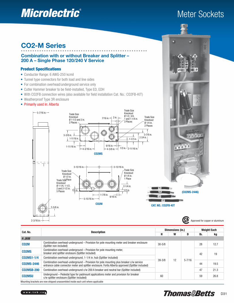
CO2MS
CO2M
(C02MS-2446)
Meter Sockets
Product Specifications• Conducter Range: 6 AWG-250 kcmil• Tunnel type connectors for both load and line sides• For combination overhead/underground service only• Cutler Hammer breaker to be field-installed, Type ED, EDH• With CO2FB connection wires (also available for field installation Cat. No.: CO2FB-KIT)• Weatherproof Type 3R enclosure• Primarily used in: Alberta
Approved for copper or aluminum
Cat. No. DescriptionDimensions (in.) Weight Each
H W D lb. kg4 JAW
CO2M Combination overhead-underground – Provision for pole mounting meter and breaker enclosure (Splitter non-included) 30-5/8
12 5-7/16
28 12.7
CO2MS Combination overhead-underground – Provision for pole mounting meter, breaker and splitter enclosure (Splitter included)
39-3/8
42 19CO2MS1-1/4 Combination overhead-underground, 1-1/4 in. hub (Splitter included)
CO2MS-2446 Combination overhead-underground – Provision for pole mounting plus breaker c/w service entrance cable connector meter and splitter enclosure. Fortis Alberta approved (Splitter included) 44 19.5
CO2MSB-200 Combination overhead-underground c/w 200 A breaker and neutral bar (Splitter included) 47 21.3
CO2MSU Underground – Pedestal type for padmount applications meter and provision for breaker c/w splitter enclosure (Splitter included) 60 59 26.8
Mounting brackets are now shipped unassembled inside each unit where applicable
CAT. NO.: CO2FB-KIT
CO2-M SeriesCombination with or without Breaker and Splitter – 200 A – Single Phase 120/240 V Service
5-7/16 in.
Trade SizeKnockoutØ 1-1/4, 1-1/2, 2 and 2-1/2 in.5 Places
2-5/8 in.
2-3/16 in.
5-15/16 in.
1-7/8 in.
7/8 in.
9/16 in.
1/2 in.
2-1/4 in.
Trade Size Knockout Ø 1/4 in.1 Place
3-13/16 in.3-13/16 in.
Trade Size Knockout Ø 1/2 in.1 Place
1-11/16 in.
1-11/16 in.
4-3/16 in. 4-3/8 in.9/16 in.
1/2 in. 2-11/16 in.
1-1/2 in.2-3/4 in.
3-7/8 in.
Trade Size Knockout Ø 1/4 in.2 Places
Trade SizeKnockoutØ 1/2, 3/4, 1 and 1-1/4 in.3 Places
2 in.7/16 in.
3-3/8 in.
Trade SizeKnockoutØ 1-1/2 and 2 in.2 Places
w w w . t n b . c aD32
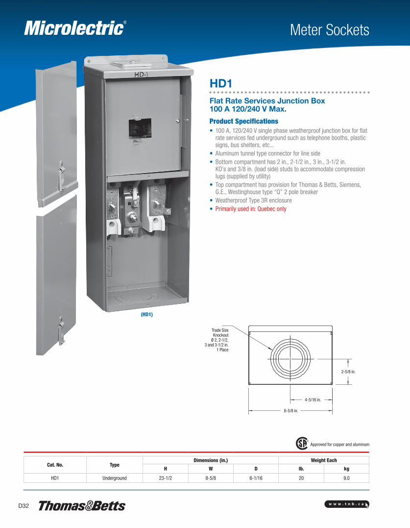
(HD1)
Meter Sockets
HD1Flat Rate Services Junction Box 100 A 120/240 V Max.
Product Specifications• 100 A, 120/240 V single phase weatherproof junction box for flat
rate services fed underground such as telephone booths, plastic signs, bus shelters, etc...
• Aluminum tunnel type connector for line side• Bottom compartment has 2 in., 2-1/2 in., 3 in., 3-1/2 in.
KO’s and 3/8 in. (load side) studs to accommodate compression lugs (supplied by utility)
• Top compartment has provision for Thomas & Betts, Siemens, G.E., Westinghouse type “Q” 2 pole breaker
• Weatherproof Type 3R enclosure• Primarily used in: Quebec only
Approved for copper and aluminum
Cat. No. TypeDimensions (in.) Weight Each
H W D lb. kg
HD1 Underground 23-1/2 8-5/8 6-1/16 20 9.0
Trade SizeKnockout
Ø 2, 2-1/2, 3 and 3-1/2 in.
1 Place
2-5/8 in.
4-5/16 in.
8-5/8 in.
w w w . t n b . c a D33
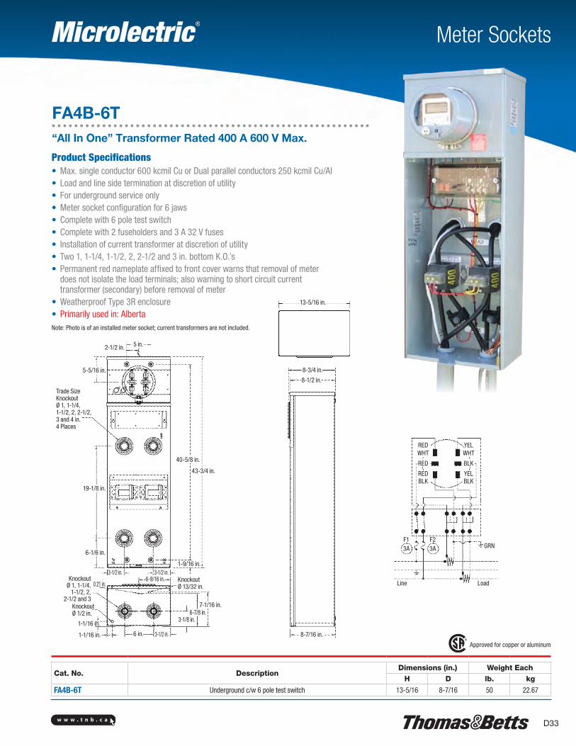
Meter Sockets
FA4B-6T“All In One” Transformer Rated 400 A 600 V Max.
Approved for copper or aluminum
Cat. No. DescriptionDimensions (in.) Weight Each
H D lb. kg
FA4B-6T Underground c/w 6 pole test switch 13-5/16 8-7/16 50 22.67
Product Specifications• Max. single conductor 600 kcmil Cu or Dual parallel conductors 250 kcmil Cu/Al• Load and line side termination at discretion of utility• For underground service only• Meter socket configuration for 6 jaws• Complete with 6 pole test switch• Complete with 2 fuseholders and 3 A 32 V fuses• Installation of current transformer at discretion of utility• Two 1, 1-1/4, 1-1/2, 2, 2-1/2 and 3 in. bottom K.O.’s• Permanent red nameplate affixed to front cover warns that removal of meter
does not isolate the load terminals; also warning to short circuit current transformer (secondary) before removal of meter
• Weatherproof Type 3R enclosure• Primarily used in: AlbertaNote: Photo is of an installed meter socket; current transformers are not included.
5 in.2-1/2 in.
5-5/16 in.
40-5/8 in.
43-3/4 in.
Trade SizeKnockoutØ 1, 1-1/4, 1-1/2, 2, 2-1/2, 3 and 4 in.4 Places
19-1/8 in.
6-1/6 in.
3-1/2 in. 3-1/2 in.1-9/16 in.
6-9/16 in. Knockout Ø 13/32 in.
7-1/16 in.6-7/8 in.
3-1/8 in.
3-1/2 in.6 in.1-1/16 in.
1-1/16 in.
Knockout Ø 1/2 in.
KnockoutØ 1, 1-1/4,
1-1/2, 2, 2-1/2 and 3
0.21 in.
8-7/16 in.
8-1/2 in.
8-3/4 in.
13-5/16 in.
RED YEL
RED BLK
RED YELBLK BLK
WHT WHT
F13A
F23A GRN
LoadLine
w w w . t n b . c aD34
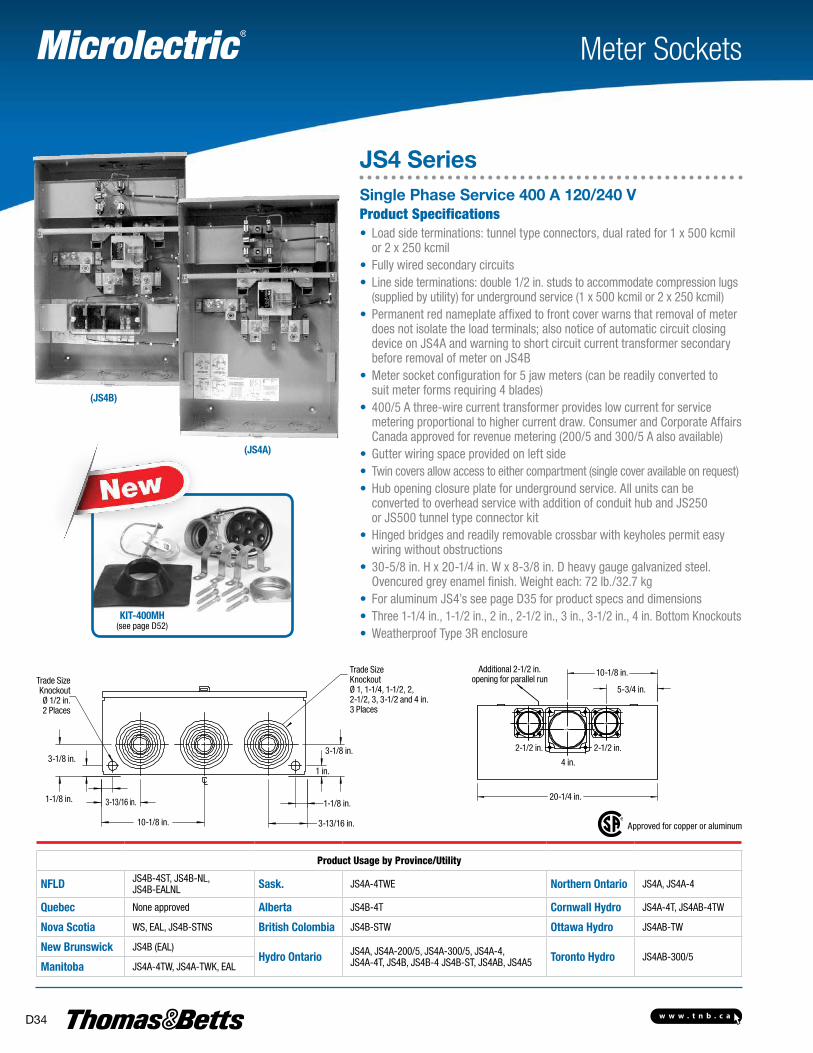
(JS4B)
(JS4A)
Product Specifications• Load side terminations: tunnel type connectors, dual rated for 1 x 500 kcmil
or 2 x 250 kcmil• Fully wired secondary circuits• Line side terminations: double 1/2 in. studs to accommodate compression lugs
(supplied by utility) for underground service (1 x 500 kcmil or 2 x 250 kcmil)• Permanent red nameplate affixed to front cover warns that removal of meter
does not isolate the load terminals; also notice of automatic circuit closing device on JS4A and warning to short circuit current transformer secondary before removal of meter on JS4B
• Meter socket configuration for 5 jaw meters (can be readily converted to suit meter forms requiring 4 blades)
• 400/5 A three-wire current transformer provides low current for service metering proportional to higher current draw. Consumer and Corporate Affairs Canada approved for revenue metering (200/5 and 300/5 A also available)
• Gutter wiring space provided on left side• Twin covers allow access to either compartment (single cover available on request)• Hub opening closure plate for underground service. All units can be
converted to overhead service with addition of conduit hub and JS250 or JS500 tunnel type connector kit
• Hinged bridges and readily removable crossbar with keyholes permit easy wiring without obstructions
• 30-5/8 in. H x 20-1/4 in. W x 8-3/8 in. D heavy gauge galvanized steel. Ovencured grey enamel finish. Weight each: 72 lb./32.7 kg
• For aluminum JS4’s see page D35 for product specs and dimensions• Three 1-1/4 in., 1-1/2 in., 2 in., 2-1/2 in., 3 in., 3-1/2 in., 4 in. Bottom Knockouts• Weatherproof Type 3R enclosure
Meter Sockets
JS4 SeriesSingle Phase Service 400 A 120/240 V
Approved for copper or aluminum
Product Usage by Province/Utility
NFLD JS4B-4ST, JS4B-NL, JS4B-EALNL Sask. JS4A-4TWE Northern Ontario JS4A, JS4A-4
Quebec None approved Alberta JS4B-4T Cornwall Hydro JS4A-4T, JS4AB-4TW
Nova Scotia WS, EAL, JS4B-STNS British Colombia JS4B-STW Ottawa Hydro JS4AB-TW
New Brunswick JS4B (EAL)Hydro Ontario JS4A, JS4A-200/5, JS4A-300/5, JS4A-4,
JS4A-4T, JS4B, JS4B-4 JS4B-ST, JS4AB, JS4A5 Toronto Hydro JS4AB-300/5Manitoba JS4A-4TW, JS4A-TWK, EAL
KIT-400MH(see page D52)
Trade Size Knockout Ø 1/2 in.2 Places
3-1/8 in.
1-1/8 in. 3-13/16 in.
10-1/8 in. 3-13/16 in.
1-1/8 in.
1 in.
3-1/8 in.
Trade Size Knockout Ø 1, 1-1/4, 1-1/2, 2, 2-1/2, 3, 3-1/2 and 4 in.3 Places
Additional 2-1/2 in. opening for parallel run
10-1/8 in.
5-3/4 in.
2-1/2 in.2-1/2 in.
4 in.
20-1/4 in.
w w w . t n b . c a D35
Meter Sockets
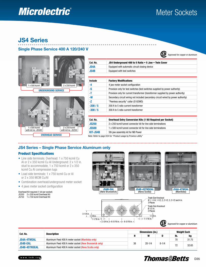
Approved for copper or aluminum
Cat. No. JS4 Underground 400 to 5 Ratio • 5 Jaw • Twin Cover
JS4A Equipped with automatic circuit closing device
JS4B Equipped with test switches
Include Factory Modifications
-4 4 jaw meter socket configuration
-S Provision only for test switches (test switches supplied by power authority)
-T Provision only for current transformer (transformer supplied by power authority)
-W Secondary circuit wiring not included (secondary circuit wired by power authority)
-Z ”Peerless security” collar (S102WD)
-200 / 5 200 A to 5 ratio current transformer
-300 / 5 300 A to 5 ratio current transformer
Cat. No. Overhead Entry Conversion Kits (1 Kit Required per Socket)
JS250 2 x 250 kcmil tunnel connector kit for line side terminations
JS500 1 x 500 kcmil tunnel connector kit for line side terminations
KIT-JS4B 5th jaw assembly kit for NB PowerNote: Refer to page D34 for “Product usage by Province utility”
UNDERGROUND SERVICE
OVERHEAD SERVICE
1 x 500 kcmil
1 x 500 kcmilwith kit no. JS500
2 x 250 kcmilwith kit no. JS250
2 x 250 kcmil
JS4B-EAL(New Brunswick)
JS4A-4TWEAL(Manitoba)
JS4B-4STNSEAL(Nova Scotia)
Product Specifications• Line side terminals: Overhead: 1 x 750 kcmil Cu
Al or 2 x 350 kcmil Cu Al Underground: 2 x 1/2 in. stud to accommodate, 1 x 750 kcmil or 2 x 350 kcmil Cu Al compression lugs
• Load side terminals: 1 x 750 kcmil Cu or Al or 2 x 350 MCM Cu/Al
• Combination overhead/underground meter socket• 4 jaws meter socket configuration
Overhead Kit required (1 kit per socket)JS350 2 x 350 kcmil Overhead KitJS750 1 x 750 kcmil Overhead Kit
Approved for copper or aluminium
Cat. No. DescriptionDimensions (in.) Weight Each
H W D lb. kgJS4A-4TWEAL Aluminum Feed 400 A meter socket (Manitoba only)
38 20-1/4 8-1/470 31.75
JS4B-EAL Aluminum Feed 400 A meter socket (New Brunswick only)72 32.65
JS4B-4STNSEAL Aluminum Feed 400 A meter socket (Nova Scotia only)
JS4 Series – Single Phase Service Aluminum only
JS4 SeriesSingle Phase Service 400 A 120/240 V
3-1/4 in.1-1/8 in. 1-1/8 in.
1-1/16 in.3-3/4 in. 6-5/16 in. 6-5/16 in.
1-1/16 in.
Trade Size Knockout Ø 1/2 in.2 Places
Trade Size Knockout Ø 1, 1-1/4, 1-1/2, 2, 2-1/2, 3, 3-1/2 and 4 in.3 Places
w w w . t n b . c aD36
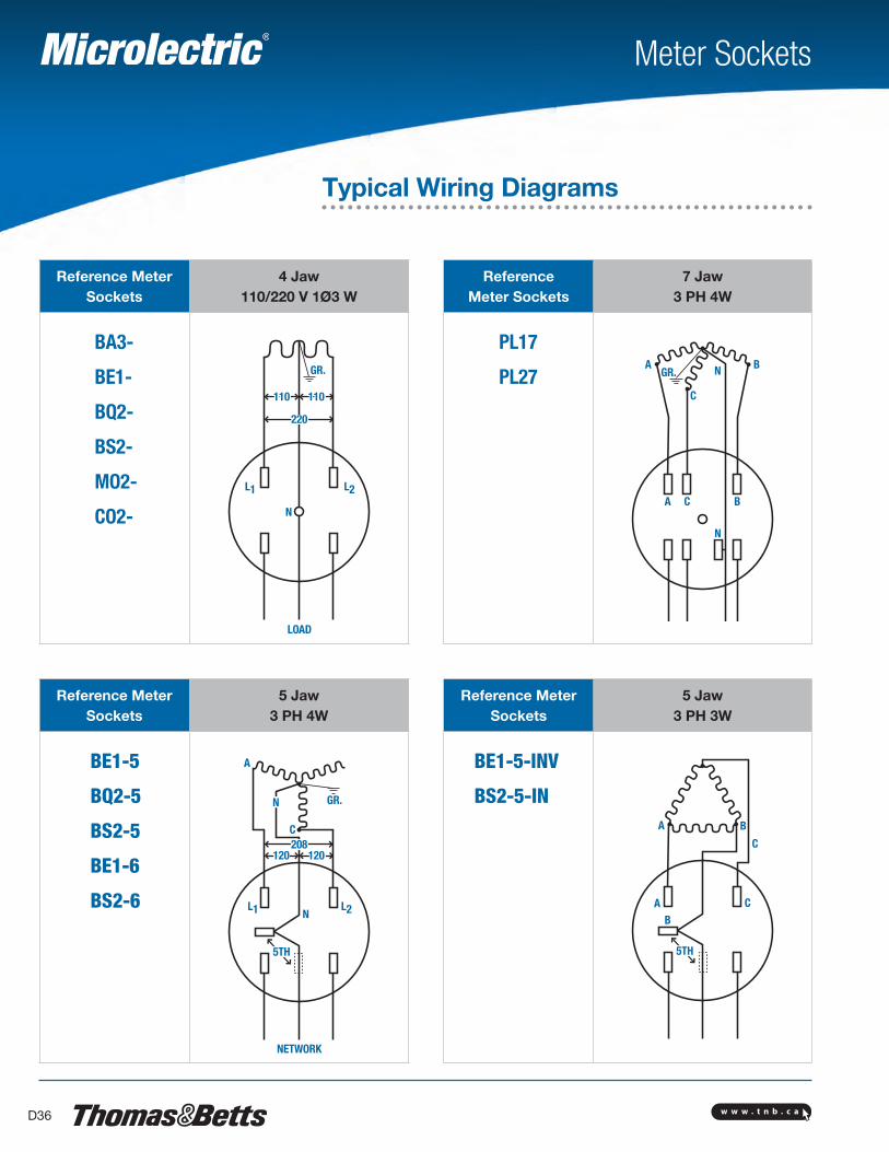
Reference Meter Sockets
4 Jaw 110/220 V 1Ø3 W
ReferenceMeter Sockets
7 Jaw3 PH 4W
BA3-
BE1-
BQ2-
BS2-
MO2-
CO2-
PL17
PL27
Reference Meter Sockets
5 Jaw3 PH 4W
Reference Meter Sockets
5 Jaw3 PH 3W
BE1-5
BQ2-5
BS2-5
BE1-6
BS2-6
BE1-5-INV
BS2-5-IN
Meter Sockets
Typical Wiring Diagrams
NETWORK
5TH
120 120
GR.
L1 L2
A
C
N
5TH
A
AB
C
B
C208
GR.
110110
220
L1 L2
N
LOAD
GR.A
A C B
C
BN
N
N
w w w . t n b . c a D37
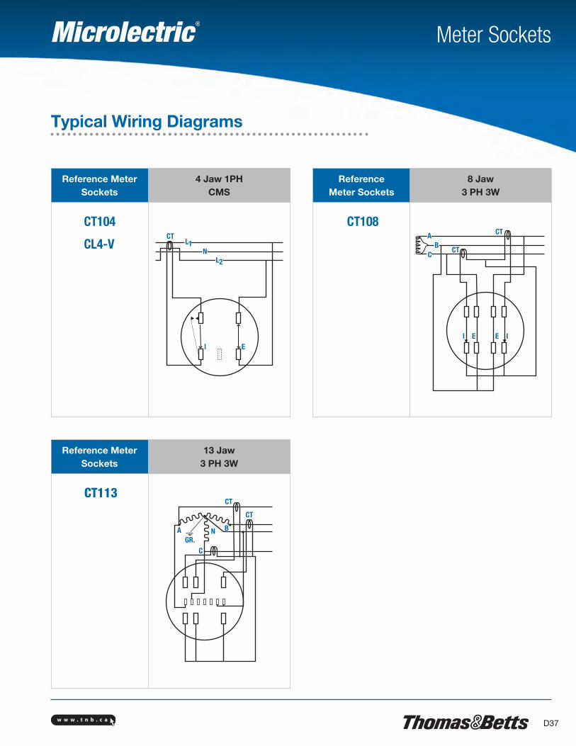
Reference Meter Sockets
4 Jaw 1PHCMS
ReferenceMeter Sockets
8 Jaw 3 PH 3W
CT104
CL4-V
CT108
Reference Meter Sockets
13 Jaw3 PH 3W
CT113
Meter Sockets
Typical Wiring Diagrams
I
AB
C
IE E
CT
CT
CT
CT
GR.A BN
C
EI
L1CT
L2N
w w w . t n b . c aD38
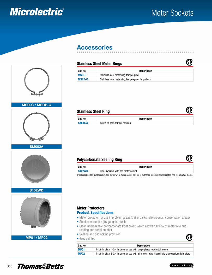
MSR-C / MSRP-C
SM002A
S102WD
MP01 / MP02
Meter Sockets
Accessories
Stainless Steel Meter Rings Cat. No. Description
MSR-C Stainless steel meter ring, tamper-proof
MSRP-C Stainless steel meter ring, tamper-proof for padlock
Stainless Steel Ring Cat. No. Description
SM002A Screw on type, tamper resistant
Polycarbonate Sealing Ring Cat. No. Description
S102WD Ring, available with any meter socketWhen ordering any meter socket, add suffix “Z” to meter socket cat. no. to exchange standard stainless steel ring for S102WD model.
Meter ProtectorsProduct Specifications• Meter protector for use in problem areas (trailer parks, playgrounds, conservation areas)• Steel construction (16 ga. galv. steel)• Clear, unbreakable polycarbonate front cover, which allows full view of meter revenue
reading and serial number• Sealing and padlocking provision• Grey painted Cat. No. DescriptionMP01 7-1/6 in. dia. x 4-3/4 in. deep for use with single phase residential meters
MP02 7-1/6 in. dia. x 8-3/4 in. deep for use with all meters, other than single phase residential meters
w w w . t n b . c a D39
BS087 / BS089 / BS090
CM-BS100
LS500
MH200
MH10X
BS052
B
B
A
Meter Sockets
Accessories
Blank Meter Cover Plates Cat. No. Description
BS087 Grey ABS
BS089 Plastic “throw-away” cover
BS090 Clear unbreakable polycarbonate
Jumper Bar Cat. No. Description
CM-BS100 200 A Max.
Meter Jaw Safety Shroud Cat. No. Description
LS500 Red polycarbonate, 100/200 A
Mast Coupler Cat. No. Description
MH200 Fits all sockets with regular 2-1/2 in. hub opening
Masts Coupler Cat. No. PVC Cat. No. A Hub Size (in.) B
MH10X — 1
For 2-1/2 in. regular hub opening (add hub adapter plate BS052 if usedwith units having 4 in. hub openings)
MH12X PH12 1-1/4
MH15X PH15 1-1/2
MH20X PH20 2
MH25X PH25 2-1/2
MH30X — 3
For 4 in. hub openingMH35X — 3-1/2
MH40X — 4Supplied with 4 Robertson head screws.
Hub Adapter Plate Cat. No. Description
BS052 Permits use of regular size hubs on larger hub openings
w w w . t n b . c aD40
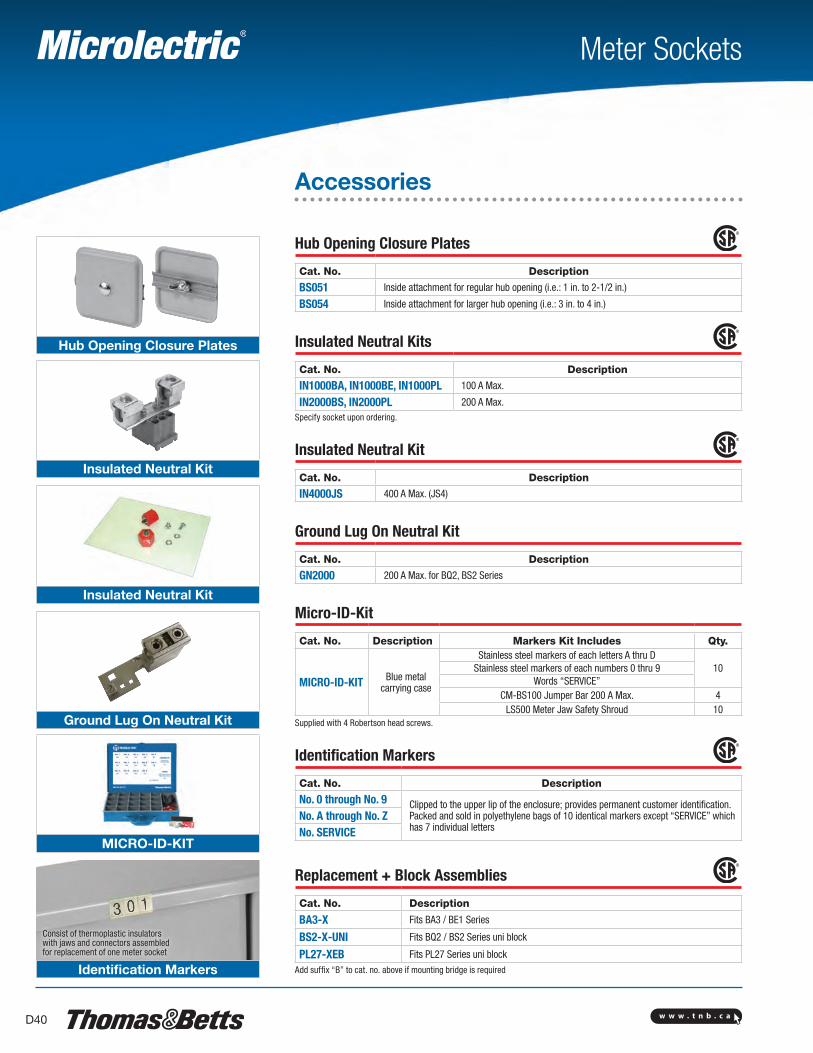
Hub Opening Closure Plates
Insulated Neutral Kit
Insulated Neutral Kit
Ground Lug On Neutral Kit
MICRO-ID-KIT
Identification Markers
Meter Sockets
Consist of thermoplastic insulators with jaws and connectors assembled for replacement of one meter socket
Accessories
Hub Opening Closure Plates Cat. No. Description
BS051 Inside attachment for regular hub opening (i.e.: 1 in. to 2-1/2 in.)
BS054 Inside attachment for larger hub opening (i.e.: 3 in. to 4 in.)
Insulated Neutral Kits Cat. No. Description
IN1000BA, IN1000BE, IN1000PL 100 A Max.
IN2000BS, IN2000PL 200 A Max.Specify socket upon ordering.
Insulated Neutral Kit Cat. No. Description
IN4000JS 400 A Max. (JS4)
Ground Lug On Neutral Kit Cat. No. Description
GN2000 200 A Max. for BQ2, BS2 Series
Micro-ID-Kit
Cat. No. Description Markers Kit Includes Qty.
MICRO-ID-KIT Blue metal carrying case
Stainless steel markers of each letters A thru D10Stainless steel markers of each numbers 0 thru 9
Words “SERVICE”CM-BS100 Jumper Bar 200 A Max. 4
LS500 Meter Jaw Safety Shroud 10Supplied with 4 Robertson head screws.
Identification Markers Cat. No. Description
No. 0 through No. 9 Clipped to the upper lip of the enclosure; provides permanent customer identification.Packed and sold in polyethylene bags of 10 identical markers except “SERVICE” which has 7 individual letters
No. A through No. ZNo. SERVICE
Replacement + Block Assemblies Cat. No. Description
BA3-X Fits BA3 / BE1 Series
BS2-X-UNI Fits BQ2 / BS2 Series uni block
PL27-XEB Fits PL27 Series uni blockAdd suffix “B” to cat. no. above if mounting bridge is required
w w w . t n b . c a D41
Meter Sockets
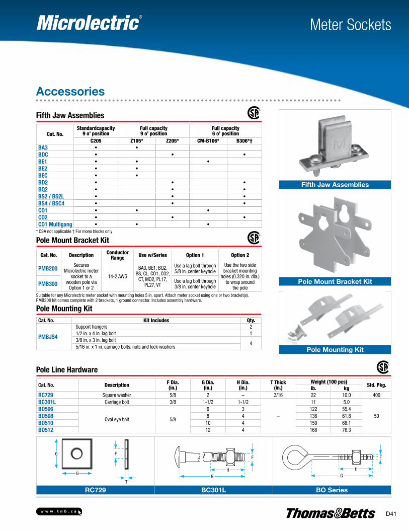
Fifth Jaw Assemblies
Cat. No.Standardcapacity
9 o’ positionFull capacity 9 o’ position
Full capacity 6 o’ position
C205 Z105* Z205* CM-B106* B306*†BA3 • •BDC • • •BE1 • • •BE2 • •BEC • •BD2 • • •BQ2 • • •BS2 / BS2L • • •BS4 / BSC4 • • •CO1 • • •CO2 • • •CO1 Multigang • • •
* CSA not applicable † For mono blocks only
Pole Mount Bracket Kit
Cat. No. Description Conductor Range Use w/Series Option 1 Option 2
PMB200Secures
Microlectric meter socket to a
wooden pole viaOption 1 or 2
14-2 AWG
BA3, BE1, BQ2, BS, CL, CO1, CO2,
CT, MO2, PL17, PL27, VT
Use a lag bolt through 5/8 in. center keyhole
Use the two side bracket mounting
holes (0.320 in. dia.) to wrap around
the polePMB300 Use a lag bolt through
3/8 in. center keyhole
Suitable for any Microlectric meter socket with mounting holes 5 in. apart. Attach meter socket using one or two bracket(s).PMB200 kit comes complete with 2 brackets, 1 ground connector. Includes assembly hardware.
Pole Mounting Kit Cat. No. Kit Includes Qty.
PMBJS4
Support hangers 21/2 in. x 4 in. lag bolt 13/8 in. x 3 in. lag bolt
45/16 in. x 1 in. carriage bolts, nuts and lock washers
Pole Line Hardware
Cat. No. Description F Dia.(in.)
G Dia.(in.)
H Dia.(in.)
T Thick(in.)
Weight (100 pcs)Std. Pkg.
lb. kgRC729 Square washer 5/8 2 – 3/16 22 10.0 400BC301L Carriage bolt 3/8 1-1/2 1-1/2
–
11 5.0
50BO506
Oval eye bolt 5/8
6 3 122 55.4BO508 8 4 136 61.8BO510 10 4 150 68.1BO512 12 4 168 76.3
Accessories
F
T
G
G
GH
F F
GH
RC729 BC301L BO Series
Fifth Jaw Assemblies
Pole Mount Bracket Kit
Pole Mounting Kit
w w w . t n b . c aD42
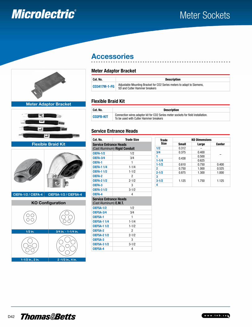
Meter Sockets
Accessories
Meter Adaptor Bracket
Cat. No. Description
CO3417M-1-FG Adjustable Mounting Bracket for CO2 Series meters to adapt to Siemens, SD and Cutler Hammer breakers
Flexible Braid Kit
Cat. No. Description
CO2FB-KIT Connection wires adaptor kit for CO2 Series meter sockets for field installation.To be used with Cutler Hammer breakers
Service Entrance Heads
Cat. No. Trade Size Trade Size
KO DimensionsSmall Large Center
1/2 0.312 –
–3/4 0.375 0.4001
0.4380.500
1-1/4 0.6251-1/2 0.610 0.750 0.4002 0.750 1.000 0.5252-1/2 0.875 1.300 1.0003
1.125 1.750 1.1253-1/24
Service Entrance Heads (Cast Aluminum) Rigid ConduitCIEFA-1/2 1/2CIEFA-3/4 3/4CIEFA-1 1CIEFA-1 1/4 1-1/4CIEFA-1 1/2 1-1/2CIEFA-2 2CIEFA-2 1/2 2-1/2CIEFA-3 3CIEFA-3 1/2 3-1/2CIEFA-4 4
Service Entrance Heads (Cast Aluminum) E.M.T.CIEFSA-1/2 1/2CIEFSA-3/4 3/4CIEFSA-1 1CIEFSA-1 1/4 1-1/4CIEFSA-1 1/2 1-1/2CIEFSA-2 2CIEFSA-2 1/2 2-1/2CIEFSA-3 3CIEFSA-3 1/2 3-1/2CIEFSA-4 4
KO Configuration
1/2 in. 3/4 in. - 1-1/4 in.
1-1/2 in., 2 in. 2 -1/2 in., 4 in.
Meter Adaptor Bracket
Flexible Braid Kit
CIEFA-1/2 / CIEFA-4 CIEFSA-1/2 / CIEFSA-4
w w w . t n b . c a D43
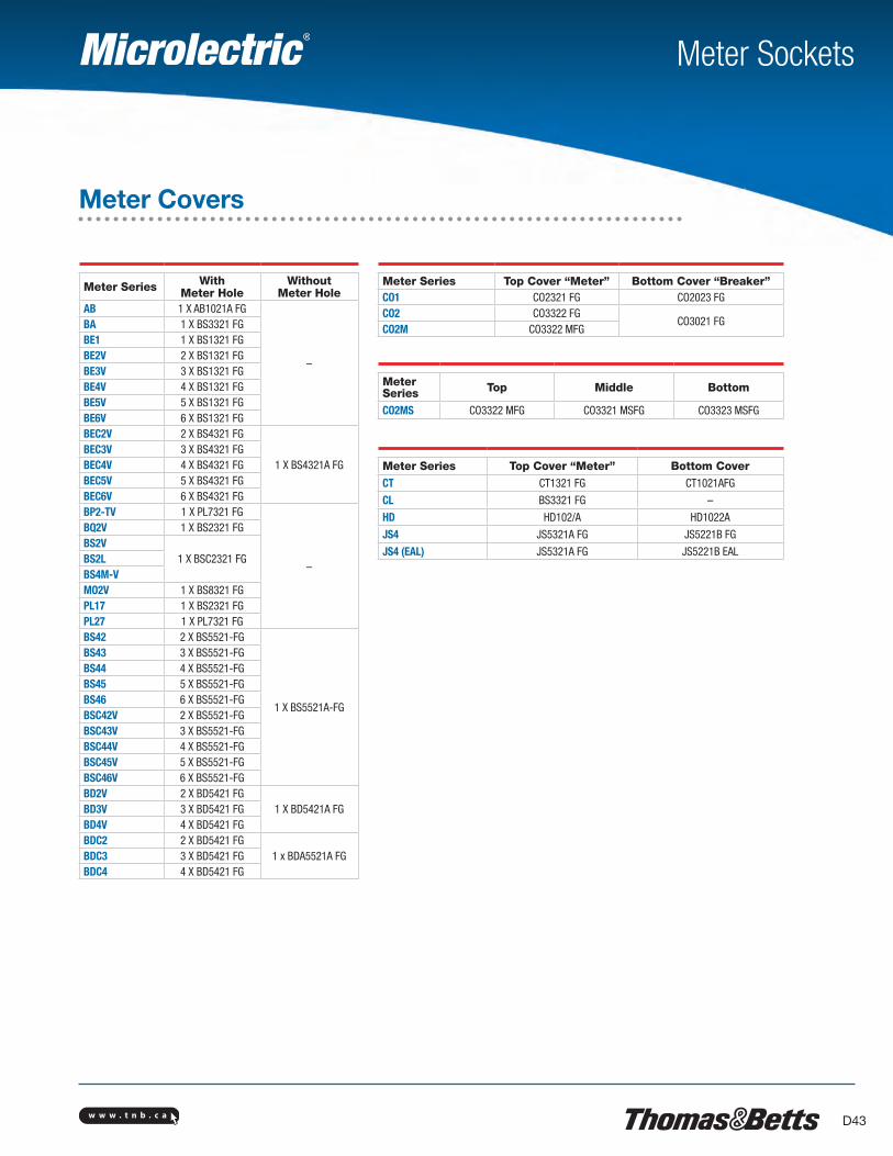
Meter Sockets
Meter Covers
Meter Series WithMeter Hole
WithoutMeter Hole
AB 1 X AB1021A FG
–
BA 1 X BS3321 FGBE1 1 X BS1321 FGBE2V 2 X BS1321 FGBE3V 3 X BS1321 FGBE4V 4 X BS1321 FGBE5V 5 X BS1321 FGBE6V 6 X BS1321 FGBEC2V 2 X BS4321 FG
1 X BS4321A FGBEC3V 3 X BS4321 FGBEC4V 4 X BS4321 FGBEC5V 5 X BS4321 FGBEC6V 6 X BS4321 FGBP2-TV 1 X PL7321 FG
–
BQ2V 1 X BS2321 FGBS2V
1 X BSC2321 FGBS2LBS4M-VMO2V 1 X BS8321 FGPL17 1 X BS2321 FGPL27 1 X PL7321 FGBS42 2 X BS5521-FG
1 X BS5521A-FG
BS43 3 X BS5521-FGBS44 4 X BS5521-FGBS45 5 X BS5521-FGBS46 6 X BS5521-FGBSC42V 2 X BS5521-FGBSC43V 3 X BS5521-FGBSC44V 4 X BS5521-FGBSC45V 5 X BS5521-FGBSC46V 6 X BS5521-FGBD2V 2 X BD5421 FG
1 X BD5421A FGBD3V 3 X BD5421 FGBD4V 4 X BD5421 FGBDC2 2 X BD5421 FG
1 x BDA5521A FGBDC3 3 X BD5421 FGBDC4 4 X BD5421 FG
Meter Series Top Cover “Meter” Bottom Cover “Breaker”CO1 CO2321 FG CO2023 FGCO2 CO3322 FG
CO3021 FGCO2M CO3322 MFG
Meter Series Top Cover “Meter” Bottom CoverCT CT1321 FG CT1021AFG
CL BS3321 FG –
HD HD102/A HD1022A
JS4 JS5321A FG JS5221B FG
JS4 (EAL) JS5321A FG JS5221B EAL
Meter Series Top Middle Bottom
CO2MS CO3322 MFG CO3321 MSFG CO3323 MSFG
w w w . t n b . c aD44
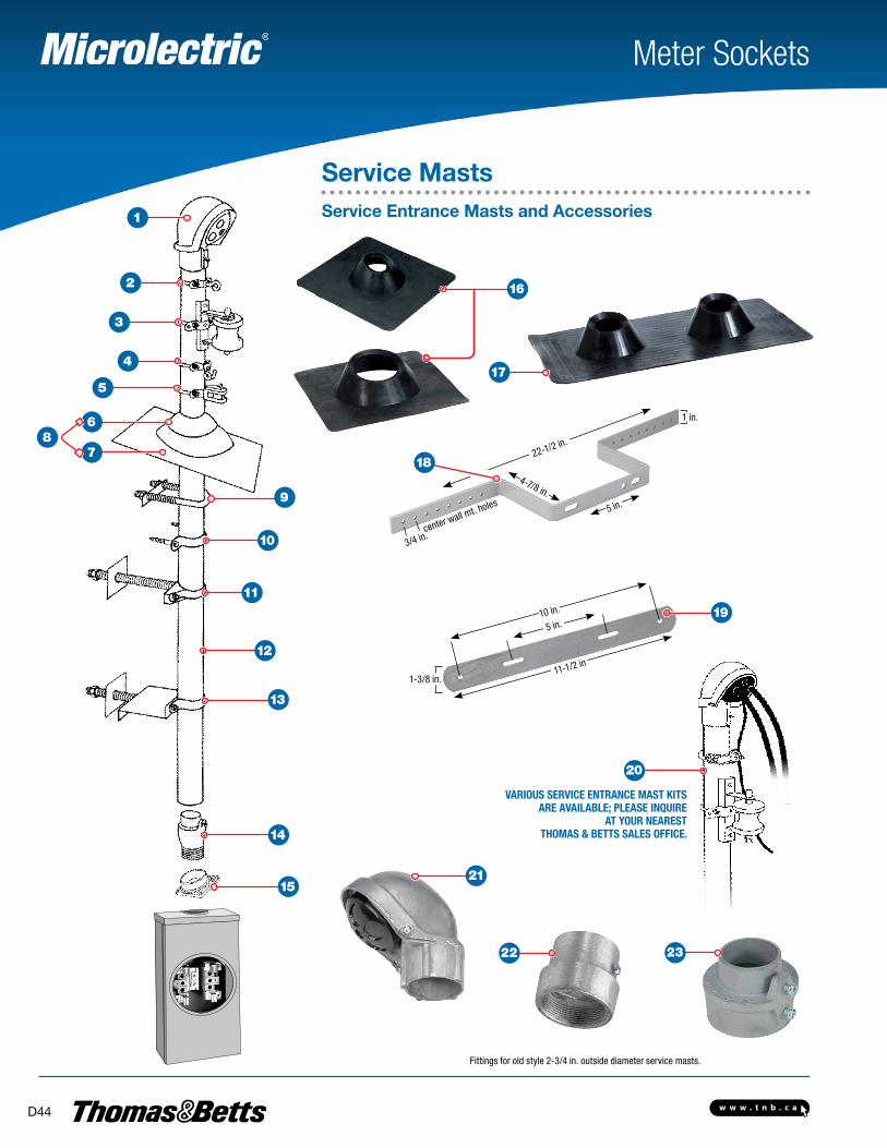
Meter Sockets
Service MastsService Entrance Masts and Accessories
11-1/2 in
10 in.
5 in.
1-3/8 in.
VARIOUS SERVICE ENTRANCE MAST KITS ARE AVAILABLE; PLEASE INQUIRE
AT YOUR NEAREST THOMAS & BETTS SALES OFFICE.
Fittings for old style 2-3/4 in. outside diameter service masts.
22-1/2 in.
4-7/8 in.
3/4 in.center wall mt. holes
1 in.
5 in.
1
2
3
4
5
6
7 8
9
13
10
12
11
14
15
18
19
20
21
22 23
17
16
w w w . t n b . c a D45
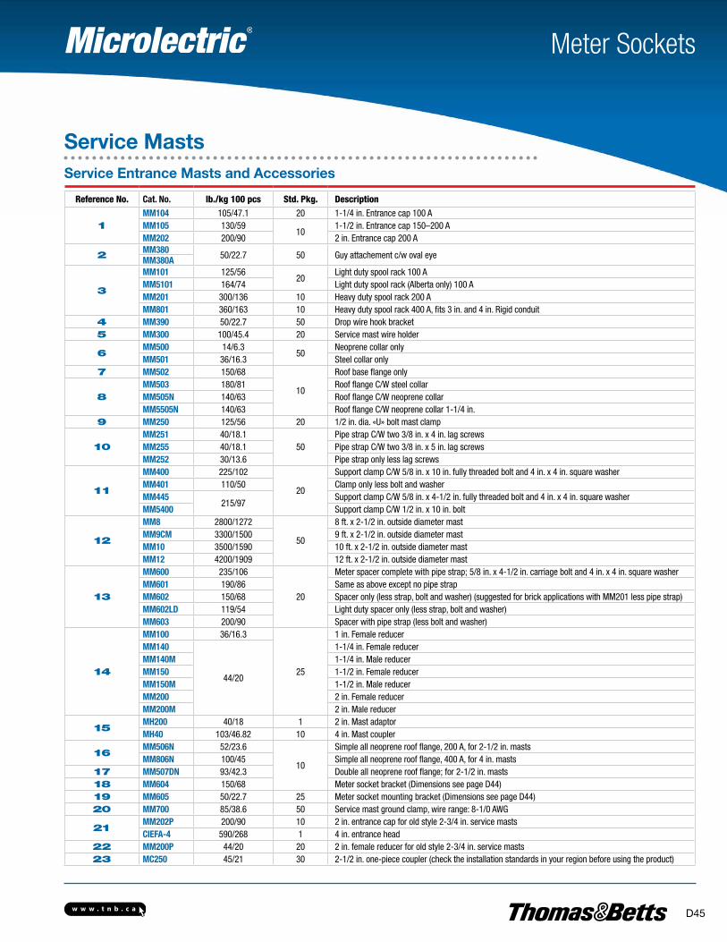
Meter Sockets
Service MastsService Entrance Masts and Accessories
Reference No. Cat. No. lb./kg 100 pcs Std. Pkg. Description
1MM104 105/47.1 20 1-1/4 in. Entrance cap 100 AMM105 130/59
101-1/2 in. Entrance cap 150–200 A
MM202 200/90 2 in. Entrance cap 200 A
2 MM380 50/22.7 50 Guy attachement c/w oval eyeMM380A
3
MM101 125/5620
Light duty spool rack 100 AMM5101 164/74 Light duty spool rack (Alberta only) 100 AMM201 300/136 10 Heavy duty spool rack 200 AMM801 360/163 10 Heavy duty spool rack 400 A, fits 3 in. and 4 in. Rigid conduit
4 MM390 50/22.7 50 Drop wire hook bracket5 MM300 100/45.4 20 Service mast wire holder
6MM500 14/6.3
50Neoprene collar only
MM501 36/16.3 Steel collar only7 MM502 150/68
10
Roof base flange only
8MM503 180/81 Roof flange C/W steel collarMM505N 140/63 Roof flange C/W neoprene collarMM5505N 140/63 Roof flange C/W neoprene collar 1-1/4 in.
9 MM250 125/56 20 1/2 in. dia. «U» bolt mast clamp
10MM251 40/18.1
50Pipe strap C/W two 3/8 in. x 4 in. lag screws
MM255 40/18.1 Pipe strap C/W two 3/8 in. x 5 in. lag screwsMM252 30/13.6 Pipe strap only less lag screws
11
MM400 225/102
20
Support clamp C/W 5/8 in. x 10 in. fully threaded bolt and 4 in. x 4 in. square washerMM401 110/50 Clamp only less bolt and washerMM445
215/97Support clamp C/W 5/8 in. x 4-1/2 in. fully threaded bolt and 4 in. x 4 in. square washer
MM5400 Support clamp C/W 1/2 in. x 10 in. bolt
12
MM8 2800/1272
50
8 ft. x 2-1/2 in. outside diameter mastMM9CM 3300/1500 9 ft. x 2-1/2 in. outside diameter mastMM10 3500/1590 10 ft. x 2-1/2 in. outside diameter mastMM12 4200/1909 12 ft. x 2-1/2 in. outside diameter mast
13
MM600 235/106
20
Meter spacer complete with pipe strap; 5/8 in. x 4-1/2 in. carriage bolt and 4 in. x 4 in. square washerMM601 190/86 Same as above except no pipe strapMM602 150/68 Spacer only (less strap, bolt and washer) (suggested for brick applications with MM201 less pipe strap)MM602LD 119/54 Light duty spacer only (less strap, bolt and washer)MM603 200/90 Spacer with pipe strap (less bolt and washer)
14
MM100 36/16.3
25
1 in. Female reducerMM140
44/20
1-1/4 in. Female reducerMM140M 1-1/4 in. Male reducerMM150 1-1/2 in. Female reducerMM150M 1-1/2 in. Male reducerMM200 2 in. Female reducerMM200M 2 in. Male reducer
15MH200 40/18 1 2 in. Mast adaptorMH40 103/46.82 10 4 in. Mast coupler
16MM506N 52/23.6
10
Simple all neoprene roof flange, 200 A, for 2-1/2 in. mastsMM806N 100/45 Simple all neoprene roof flange, 400 A, for 4 in. masts
17 MM507DN 93/42.3 Double all neoprene roof flange; for 2-1/2 in. masts18 MM604 150/68 Meter socket bracket (Dimensions see page D44)19 MM605 50/22.7 25 Meter socket mounting bracket (Dimensions see page D44)20 MM700 85/38.6 50 Service mast ground clamp, wire range: 8-1/0 AWG
21MM202P 200/90 10 2 in. entrance cap for old style 2-3/4 in. service mastsCIEFA-4 590/268 1 4 in. entrance head
22 MM200P 44/20 20 2 in. female reducer for old style 2-3/4 in. service masts23 MC250 45/21 30 2-1/2 in. one-piece coupler (check the installation standards in your region before using the product)
w w w . t n b . c aD46
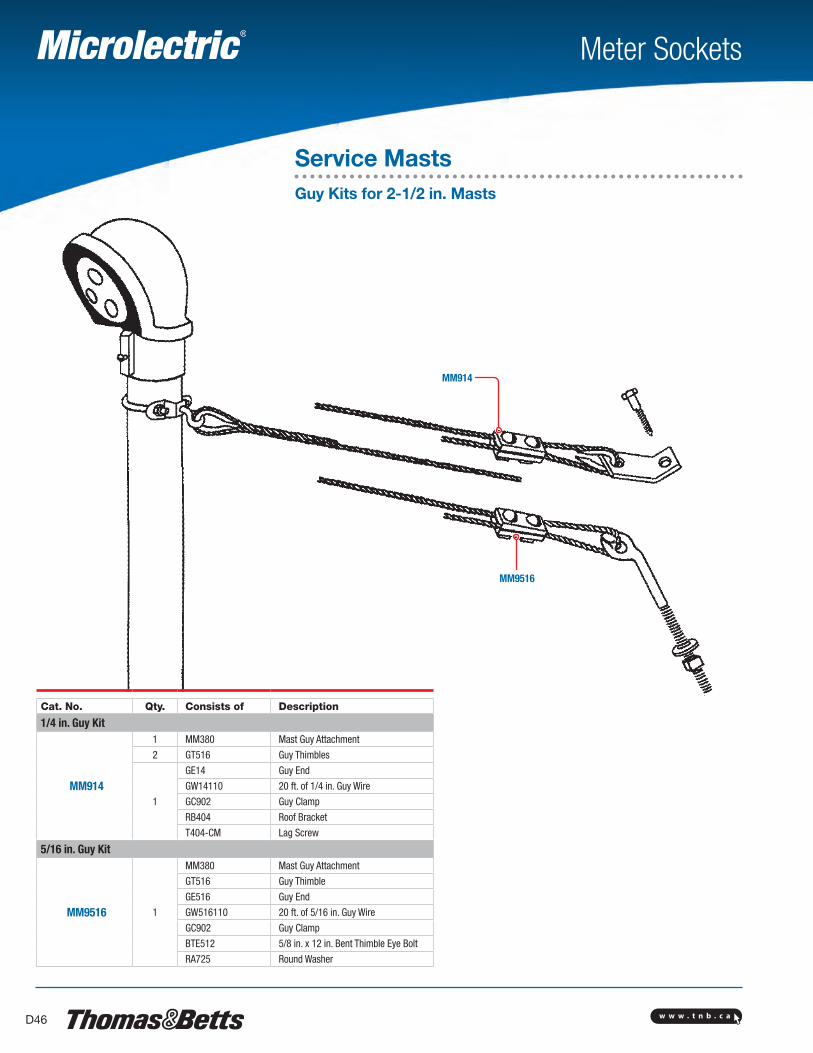
MM914
MM9516
Meter Sockets
Service MastsGuy Kits for 2-1/2 in. Masts
Cat. No. Qty. Consists of Description
1/4 in. Guy Kit
MM914
1 MM380 Mast Guy Attachment
2 GT516 Guy Thimbles
1
GE14 Guy End
GW14110 20 ft. of 1/4 in. Guy Wire
GC902 Guy Clamp
RB404 Roof Bracket
T404-CM Lag Screw
5/16 in. Guy Kit
MM9516 1
MM380 Mast Guy Attachment
GT516 Guy Thimble
GE516 Guy End
GW516110 20 ft. of 5/16 in. Guy Wire
GC902 Guy Clamp
BTE512 5/8 in. x 12 in. Bent Thimble Eye Bolt
RA725 Round Washer
w w w . t n b . c a D47
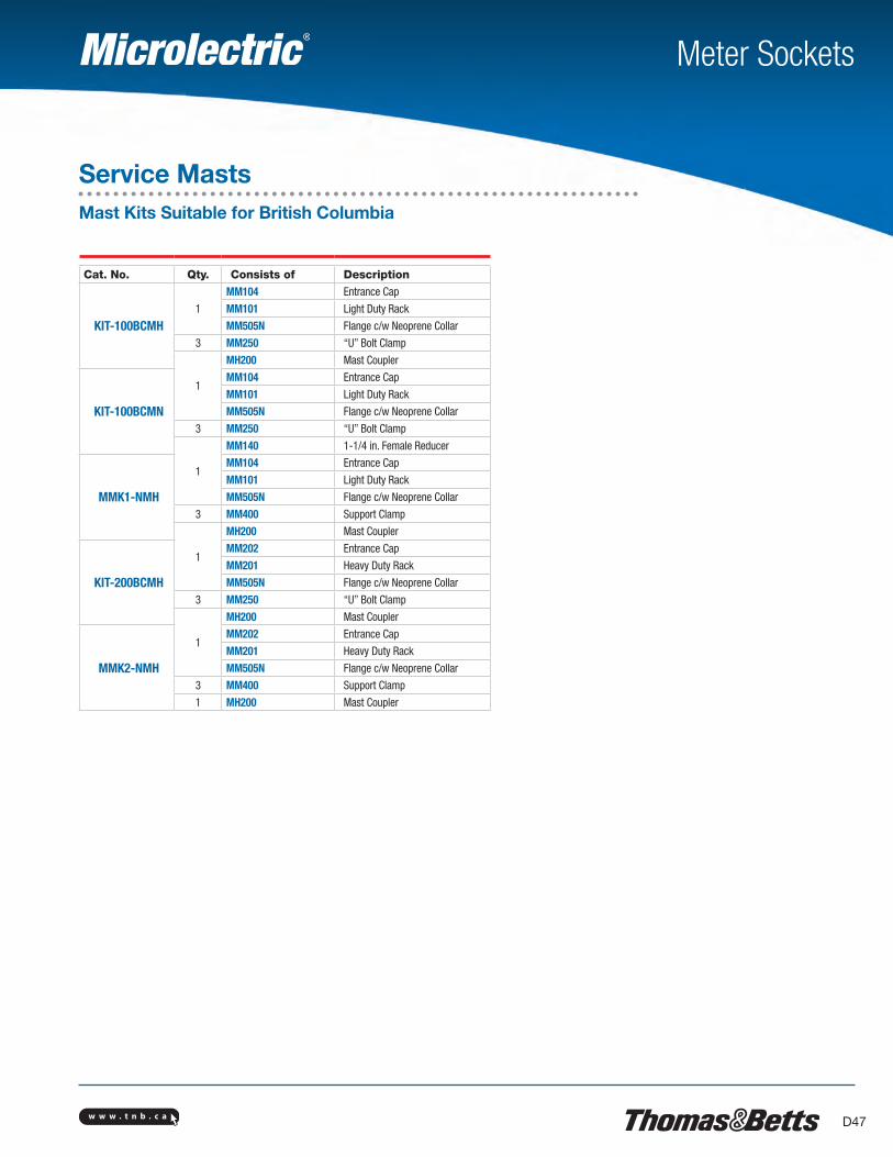
Meter Sockets
Service MastsMast Kits Suitable for British Columbia
Cat. No. Qty. Consists of Description
KIT-100BCMH1
MM104 Entrance Cap
MM101 Light Duty Rack
MM505N Flange c/w Neoprene Collar
3 MM250 “U” Bolt Clamp
1
MH200 Mast Coupler
KIT-100BCMN
MM104 Entrance Cap
MM101 Light Duty Rack
MM505N Flange c/w Neoprene Collar
3 MM250 “U” Bolt Clamp
1
MM140 1-1/4 in. Female Reducer
MMK1-NMH
MM104 Entrance Cap
MM101 Light Duty Rack
MM505N Flange c/w Neoprene Collar
3 MM400 Support Clamp
1
MH200 Mast Coupler
KIT-200BCMH
MM202 Entrance Cap
MM201 Heavy Duty Rack
MM505N Flange c/w Neoprene Collar
3 MM250 “U” Bolt Clamp
1
MH200 Mast Coupler
MMK2-NMH
MM202 Entrance Cap
MM201 Heavy Duty Rack
MM505N Flange c/w Neoprene Collar
3 MM400 Support Clamp
1 MH200 Mast Coupler
w w w . t n b . c aD48
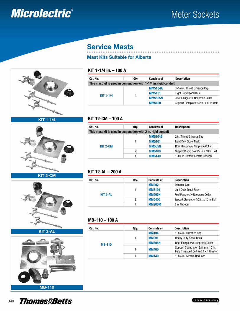
KIT 1-1/4
KIT 2-CM
KIT 2-AL
MB-110
Meter Sockets
KIT 1-1/4 in. – 100 A
Cat. No. Qty. Consists of Description
This mast kit is used in conjunction with 1-1/4 in. rigid conduit
KIT 1-1/4 1
MM5104A 1-1/4 in. Throat Entrance Cap
MM5101 Light Duty Spool Rack
MM5505N Roof Flange c/w Neoprene Collar
MM5400 Support Clamp c/w 1/2 in. x 10 in. Bolt
KIT 12-CM – 100 A
Cat. No. Qty. Consists of Description
This mast kit is used in conjunction with 2 in. rigid conduit
KIT 2-CM1
MM5104B 2 in. Throat Entrance Cap
MM5101 Light Duty Spool Rack
MM505N Roof Flange c/w Neoprene Collar
2 MM5400 Support Clamp c/w 1/2 in. x 10 in. Bolt
1 MM5140 1-1/4 in. Bottom Female Reducer
KIT 12-AL – 200 A
Cat. No. Qty. Consists of Description
KIT 2-AL1
MM202 Entrance Cap
MM5101 Light Duty Spool Rack
MM505N Roof Flange c/w Neoprene Collar
2 MM5400 Support Clamp c/w 1/2 in. x 10 in. Bolt
1 MM200M 2 in. Reducer
MB-110 – 100 A
Cat. No. Qty. Consists of Description
MB-110
1
MM104 1-1/4 in. Entrance Cap
MM201 Heavy Duty Spool Rack
MM505N Roof Flange c/w Neoprene Collar
3 MM400 Support Clamp c/w 5/8 in. x 10 in. Fully Threaded Bolt and 4 x 4 Washer
1 MM140 1-1/4 in. Female Reducer
Service MastsMast Kits Suitable for Alberta
w w w . t n b . c a D49
Meter Sockets
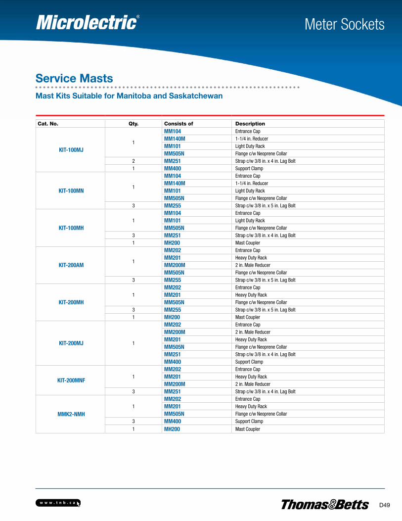
Cat. No. Qty. Consists of Description
KIT-100MJ1
MM104 Entrance Cap
MM140M 1-1/4 in. Reducer
MM101 Light Duty Rack
MM505N Flange c/w Neoprene Collar2 MM251 Strap c/w 3/8 in. x 4 in. Lag Bolt1 MM400 Support Clamp
KIT-100MN1
MM104 Entrance Cap
MM140M 1-1/4 in. Reducer
MM101 Light Duty Rack
MM505N Flange c/w Neoprene Collar3 MM255 Strap c/w 3/8 in. x 5 in. Lag Bolt
KIT-100MH1
MM104 Entrance Cap
MM101 Light Duty Rack
MM505N Flange c/w Neoprene Collar3 MM251 Strap c/w 3/8 in. x 4 in. Lag Bolt1 MH200 Mast Coupler
KIT-200AM1
MM202 Entrance Cap
MM201 Heavy Duty Rack
MM200M 2 in. Male Reducer
MM505N Flange c/w Neoprene Collar3 MM255 Strap c/w 3/8 in. x 5 in. Lag Bolt
KIT-200MH1
MM202 Entrance Cap
MM201 Heavy Duty Rack
MM505N Flange c/w Neoprene Collar3 MM255 Strap c/w 3/8 in. x 5 in. Lag Bolt1 MH200 Mast Coupler
KIT-200MJ 1
MM202 Entrance Cap
MM200M 2 in. Male Reducer
MM201 Heavy Duty Rack
MM505N Flange c/w Neoprene Collar
MM251 Strap c/w 3/8 in. x 4 in. Lag Bolt
MM400 Support Clamp
KIT-200MNF1
MM202 Entrance Cap
MM201 Heavy Duty Rack
MM200M 2 in. Male Reducer3 MM251 Strap c/w 3/8 in. x 4 in. Lag Bolt
MMK2-NMH1
MM202 Entrance Cap
MM201 Heavy Duty Rack
MM505N Flange c/w Neoprene Collar3 MM400 Support Clamp
1 MH200 Mast Coupler
Service MastsMast Kits Suitable for Manitoba and Saskatchewan
w w w . t n b . c aD50
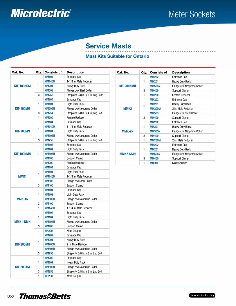
Meter Sockets
Service MastsMast Kits Suitable for Ontario
Cat. No. Qty. Consists of Description Cat. No. Qty. Consists of Description
KIT-200NMH1
MM202 Entrance Cap
MM201 Heavy Duty Rack
MM505N Flange c/w Neoprene Collar
3 MM400 Support Clamp
1 MM200 Female Reducer
MMK21
MM202 Entrance Cap
MM201 Heavy Duty Rack
MM200M 2 in. Male Reducer
MM503 Flange c/w Steel Collar
3 MM400 Support Clamp
MMK-2N1
MM202 Entrance Cap
MM201 Heavy Duty Rack
MM505N Flange c/w Neoprene Collar
3 MM400 Support Clamp
1 MM200M 2 in. Male Reducer
MMK2-NMH1
MM202 Entrance Cap
MM201 Heavy Duty Rack
MM505N Flange c/w Neoprene Collar
3 MM400 Support Clamp
1 MH200 Mast Coupler
KIT-100HDM1
MM104 Entrance Cap
MM140M 1-1/4 in. Male Reducer
MM201 Heavy Duty Rack
MM503 Flange c/w Steel Collar
3 MM255 Strap c/w 3/8 in. x 5 in. Lag Bolts
KIT-100MH1
MM104 Entrance Cap
MM101 Light Duty Rack
MM505N Flange c/w Neoprene Collar
3 MM251 Strap c/w 3/8 in. x 4 in. Lag Bolt
1 MM200 Female Reducer
KIT-100MN1
MM104 Entrance Cap
MM140M 1-1/4 in. Male Reducer
MM101 Light Duty Rack
MM505N Flange c/w Neoprene Collar
3 MM255 Strap c/w 3/8 in. x 5 in. Lag Bolt
KIT-100NMH 1
MM104 Entrance Cap
MM101 Light Duty Rack
MM505N Flange c/w Neoprene Collar
MM400 Support Clamp
MM200 Female Reducer
MMK11
MM104 Entrance Cap
MM101 Light Duty Rack
MM140M 1-1/4 in. Male Reducer
MM503 Flange c/w Steel Collar
3 MM400 Support Clamp
MMK-1N1
MM104 Entrance Cap
MM101 Light Duty Rack
MM505N Flange c/w Neoprene Collar
3 MM400 Support Clamp
1 MM140M 1-1/4 in. Male Reducer
MMK1-NMH1
MM104 Entrance Cap
MM101 Light Duty Rack
MM505N Flange c/w Neoprene Collar
3 MM400 Support Clamp
1 MH200 Mast Coupler
KIT-200MH1
MM202 Entrance Cap
MM201 Heavy Duty Rack
MM200M 2 in. Male Reducer
MM505N Flange c/w Neoprene Collar
3 MM255 Strap c/w 3/8 in. x 5 in. Lag Bolt
KIT-200AM1
MM202 Entrance Cap
MM201 Heavy Duty Rack
MM505N Flange c/w Neoprene Collar
3 MM255 Strap c/w 3/8 in. x 5 in. Lag Bolt
1 MH200 Mast Coupler
w w w . t n b . c a D51
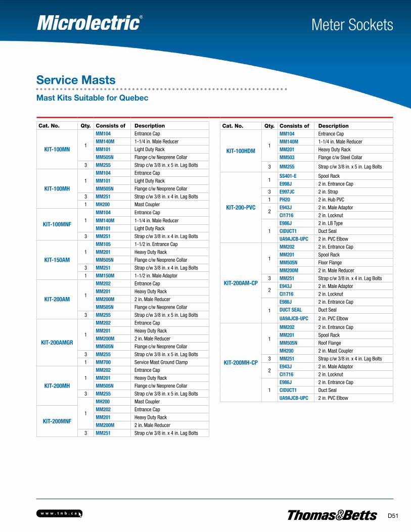
Meter Sockets
Service MastsMast Kits Suitable for Quebec
Cat. No. Qty. Consists of Description Cat. No. Qty. Consists of Description
KIT-100HDM1
MM104 Entrance Cap
MM140M 1-1/4 in. Male Reducer
MM201 Heavy Duty Rack
MM503 Flange c/w Steel Collar
3 MM255 Strap c/w 3/8 in. x 5 in. Lag Bolts
KIT-200-PVC
1SS401-E Spool Rack
E998J 2 in. Entrance Cap
3 E997JC 2 in. Strap
1 PH20 2 in. Hub PVC
2E943J 2 in. Male Adaptor
CI1716 2 in. Locknut
1
E986J 2 in. LB Type
CIDUCT1 Duct Seal
UA9AJCB-UPC 2 in. PVC Elbow
KIT-200AM-CP
1
MM202 2 in. Entrance Cap
MM201 Spool Rack
MM505N Floor Flange
MM200M 2 in. Male Reducer
3 MM251 Strap c/w 3/8 in. x 4 in. Lag Bolts
2E943J 2 in. Male Adaptor
CI1716 2 in. Locknut
1
E986J 2 in. Entrance Cap
DUCT SEAL Duct Seal
UA9AJCB-UPC 2 in. PVC Elbow
KIT-200MH-CP
1
MM202 2 in. Entrance Cap
MM201 Spool Rack
MM505N Roof Flange
MH200 2 in. Mast Coupler
3 MM251 Strap c/w 3/8 in. x 4 in. Lag Bolts
2E943J 2 in. Male Adaptor
CI1716 2 in. Locknut
1
E986J 2 in. Entrance Cap
CIDUCT1 Duct Seal
UA9AJCB-UPC 2 in. PVC Elbow
KIT-100MN1
MM104 Entrance Cap
MM140M 1-1/4 in. Male Reducer
MM101 Light Duty Rack
MM505N Flange c/w Neoprene Collar
3 MM255 Strap c/w 3/8 in. x 5 in. Lag Bolts
KIT-100MH1
MM104 Entrance Cap
MM101 Light Duty Rack
MM505N Flange c/w Neoprene Collar
3 MM251 Strap c/w 3/8 in. x 4 in. Lag Bolts
1 MH200 Mast Coupler
KIT-100MNF1
MM104 Entrance Cap
MM140M 1-1/4 in. Male Reducer
MM101 Light Duty Rack
3 MM251 Strap c/w 3/8 in. x 4 in. Lag Bolts
KIT-150AM1
MM105 1-1/2 in. Entrance Cap
MM201 Heavy Duty Rack
MM505N Flange c/w Neoprene Collar
3 MM251 Strap c/w 3/8 in. x 4 in. Lag Bolts
1 MM150M 1-1/2 in. Male Adaptor
KIT-200AM1
MM202 Entrance Cap
MM201 Heavy Duty Rack
MM200M 2 in. Male Reducer
MM505N Flange c/w Neoprene Collar
3 MM255 Strap c/w 3/8 in. x 5 in. Lag Bolts
KIT-200AMGR1
MM202 Entrance Cap
MM201 Heavy Duty Rack
MM200M 2 in. Male Reducer
MM505N Flange c/w Neoprene Collar
3 MM255 Strap c/w 3/8 in. x 5 in. Lag Bolts
1 MM700 Service Mast Ground Clamp
KIT-200MH1
MM202 Entrance Cap
MM201 Heavy Duty Rack
MM505N Flange c/w Neoprene Collar
3 MM255 Strap c/w 3/8 in. x 5 in. Lag Bolts
1
MH200 Mast Coupler
KIT-200MNF
MM202 Entrance Cap
MM201 Heavy Duty Rack
MM200M 2 in. Male Reducer
3 MM251 Strap c/w 3/8 in. x 4 in. Lag Bolts
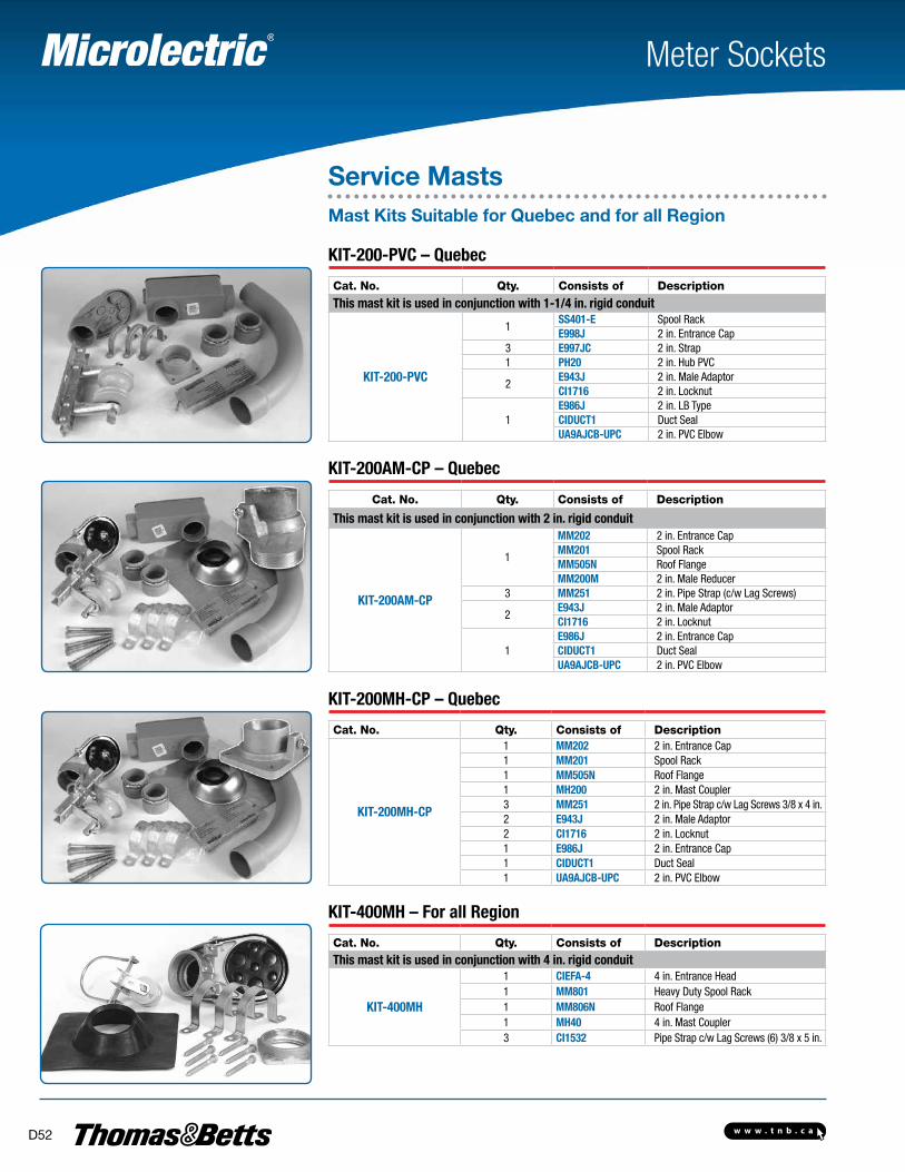
w w w . t n b . c aD52
Meter Sockets
KIT-200-PVC – Quebec
Cat. No. Qty. Consists of Description
This mast kit is used in conjunction with 1-1/4 in. rigid conduit
KIT-200-PVC
1SS401-E Spool RackE998J 2 in. Entrance Cap
3 E997JC 2 in. Strap1 PH20 2 in. Hub PVC
2E943J 2 in. Male AdaptorCI1716 2 in. Locknut
1E986J 2 in. LB TypeCIDUCT1 Duct SealUA9AJCB-UPC 2 in. PVC Elbow
KIT-200AM-CP – Quebec Cat. No. Qty. Consists of Description
This mast kit is used in conjunction with 2 in. rigid conduit
KIT-200AM-CP
1
MM202 2 in. Entrance CapMM201 Spool RackMM505N Roof FlangeMM200M 2 in. Male Reducer
3 MM251 2 in. Pipe Strap (c/w Lag Screws)
2E943J 2 in. Male AdaptorCI1716 2 in. Locknut
1E986J 2 in. Entrance CapCIDUCT1 Duct SealUA9AJCB-UPC 2 in. PVC Elbow
KIT-200MH-CP – Quebec
Cat. No. Qty. Consists of Description
KIT-200MH-CP
1 MM202 2 in. Entrance Cap1 MM201 Spool Rack1 MM505N Roof Flange1 MH200 2 in. Mast Coupler3 MM251 2 in. Pipe Strap c/w Lag Screws 3/8 x 4 in.2 E943J 2 in. Male Adaptor2 CI1716 2 in. Locknut1 E986J 2 in. Entrance Cap1 CIDUCT1 Duct Seal1 UA9AJCB-UPC 2 in. PVC Elbow
KIT-400MH – For all Region
Cat. No. Qty. Consists of DescriptionThis mast kit is used in conjunction with 4 in. rigid conduit
KIT-400MH
1 CIEFA-4 4 in. Entrance Head1 MM801 Heavy Duty Spool Rack1 MM806N Roof Flange1 MH40 4 in. Mast Coupler3 CI1532 Pipe Strap c/w Lag Screws (6) 3/8 x 5 in.
Service MastsMast Kits Suitable for Quebec and for all Region
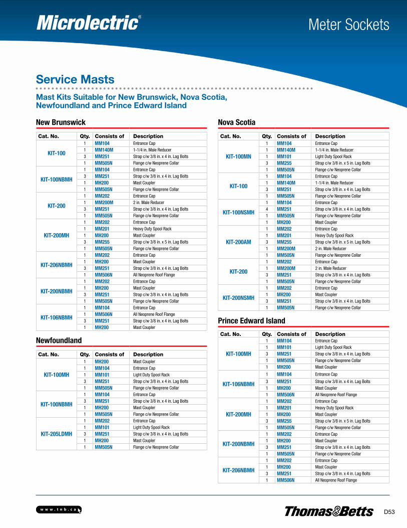
w w w . t n b . c a D53
Meter Sockets
Service MastsMast Kits Suitable for New Brunswick, Nova Scotia, Newfoundland and Prince Edward Island
New Brunswick
Cat. No. Qty. Consists of Description
KIT-100
1 MM104 Entrance Cap1 MM140M 1-1/4 in. Male Reducer3 MM251 Strap c/w 3/8 in. x 4 in. Lag Bolts1 MM505N Flange c/w Neoprene Collar
KIT-100NBMH
1 MM104 Entrance Cap3 MM251 Strap c/w 3/8 in. x 4 in. Lag Bolts1 MH200 Mast Coupler1 MM505N Flange c/w Neoprene Collar
KIT-200
1 MM202 Entrance Cap1 MM200M 2 in. Male Reducer3 MM251 Strap c/w 3/8 in. x 4 in. Lag Bolts1 MM505N Flange c/w Neoprene Collar
KIT-200MH
1 MM202 Entrance Cap1 MM201 Heavy Duty Spool Rack1 MH200 Mast Coupler3 MM255 Strap c/w 3/8 in. x 5 in. Lag Bolts1 MM505N Flange c/w Neoprene Collar
KIT-206NBMH
1 MM202 Entrance Cap1 MH200 Mast Coupler3 MM251 Strap c/w 3/8 in. x 4 in. Lag Bolts1 MM506N All Neoprene Roof Flange
KIT-200NBMH
1 MM202 Entrance Cap1 MH200 Mast Coupler3 MM251 Strap c/w 3/8 in. x 4 in. Lag Bolts1 MM505N Flange c/w Neoprene Collar
KIT-106NBMH
1 MM104 Entrance Cap1 MM506N All Neoprene Roof Flange3 MM251 Strap c/w 3/8 in. x 4 in. Lag Bolts1 MH200 Mast Coupler
Newfoundland
Cat. No. Qty. Consists of Description
KIT-100MH
1 MH200 Mast Coupler1 MM104 Entrance Cap1 MM101 Light Duty Spool Rack3 MM251 Strap c/w 3/8 in. x 4 in. Lag Bolts1 MM505N Flange c/w Neoprene Collar
KIT-100NBMH
1 MM104 Entrance Cap3 MM251 Strap c/w 3/8 in. x 4 in. Lag Bolts1 MH200 Mast Coupler1 MM505N Flange c/w Neoprene Collar
KIT-205LDMH
1 MM202 Entrance Cap1 MM101 Light Duty Spool Rack3 MM251 Strap c/w 3/8 in. x 4 in. Lag Bolts1 MH200 Mast Coupler1 MM505N Flange c/w Neoprene Collar
Nova Scotia
Cat. No. Qty. Consists of Description
KIT-100MN
1 MM104 Entrance Cap1 MM140M 1-1/4 in. Male Reducer1 MM101 Light Duty Spool Rack3 MM255 Strap c/w 3/8 in. x 5 in. Lag Bolts1 MM505N Flange c/w Neoprene Collar
KIT-100
1 MM104 Entrance Cap1 MM140M 1-1/4 in. Male Reducer3 MM251 Strap c/w 3/8 in. x 4 in. Lag Bolts1 MM505N Flange c/w Neoprene Collar
KIT-100NSMH
1 MM104 Entrance Cap4 MM251 Strap c/w 3/8 in. x 4 in. Lag Bolts1 MM505N Flange c/w Neoprene Collar1 MH200 Mast Coupler
KIT-200AM
1 MM202 Entrance Cap1 MM201 Heavy Duty Spool Rack3 MM255 Strap c/w 3/8 in. x 5 in. Lag Bolts1 MM200M 2 in. Male Reducer1 MM505N Flange c/w Neoprene Collar
KIT-200
1 MM202 Entrance Cap1 MM200M 2 in. Male Reducer3 MM251 Strap c/w 3/8 in. x 4 in. Lag Bolts1 MM505N Flange c/w Neoprene Collar
KIT-200NSMH
1 MM202 Entrance Cap1 MH200 Mast Coupler3 MM251 Strap c/w 3/8 in. x 4 in. Lag Bolts1 MM505N Flange c/w Neoprene Collar
Prince Edward Island
Cat. No. Qty. Consists of Description
KIT-100MH
1 MM104 Entrance Cap1 MM101 Light Duty Spool Rack3 MM251 Strap c/w 3/8 in. x 4 in. Lag Bolts1 MM505N Flange c/w Neoprene Collar1 MH200 Mast Coupler
KIT-106NBMH
1 MM104 Entrance Cap
3 MM251 Strap c/w 3/8 in. x 4 in. Lag Bolts1 MH200 Mast Coupler1 MM506N All Neoprene Roof Flange
KIT-200MH
1 MM202 Entrance Cap1 MM201 Heavy Duty Spool Rack1 MH200 Mast Coupler3 MM255 Strap c/w 3/8 in. x 5 in. Lag Bolts1 MM505N Flange c/w Neoprene Collar
KIT-200NBMH
1 MM202 Entrance Cap1 MH200 Mast Coupler3 MM251 Strap c/w 3/8 in. x 4 in. Lag Bolts1 MM505N Flange c/w Neoprene Collar
KIT-206NBMH
1 MM202 Entrance Cap1 MH200 Mast Coupler3 MM251 Strap c/w 3/8 in. x 4 in. Lag Bolts1 MM506N All Neoprene Roof Flange
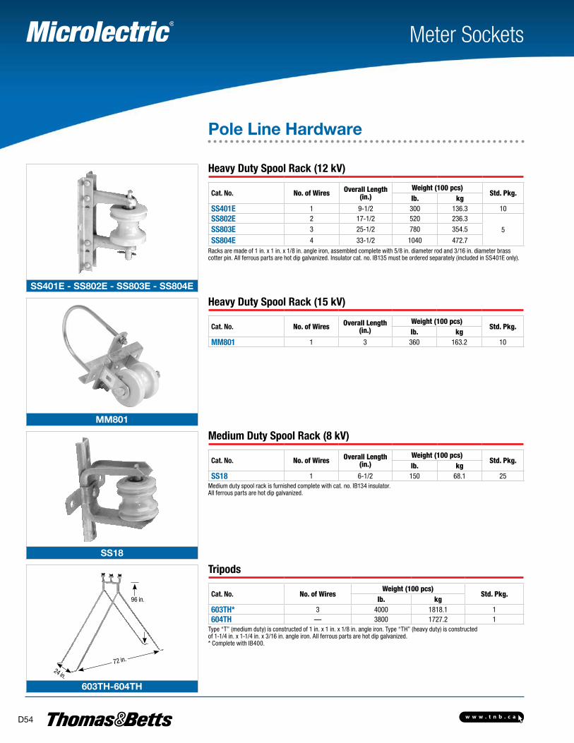
w w w . t n b . c aD54
SS401E - SS802E - SS803E - SS804E
MM801
SS18
603TH-604TH
Meter Sockets
Pole Line Hardware
Heavy Duty Spool Rack (12 kV)
Cat. No. No. of Wires Overall Length (in.)
Weight (100 pcs)Std. Pkg.
lb. kgSS401E 1 9-1/2 300 136.3 10SS802E 2 17-1/2 520 236.3
5SS803E 3 25-1/2 780 354.5
SS804E 4 33-1/2 1040 472.7Racks are made of 1 in. x 1 in. x 1/8 in. angle iron, assembled complete with 5/8 in. diameter rod and 3/16 in. diameter brass cotter pin. All ferrous parts are hot dip galvanized. Insulator cat. no. IB135 must be ordered separately (included in SS401E only).
Heavy Duty Spool Rack (15 kV)
Cat. No. No. of Wires Overall Length (in.)
Weight (100 pcs)Std. Pkg.
lb. kgMM801 1 3 360 163.2 10
Medium Duty Spool Rack (8 kV)
Cat. No. No. of Wires Overall Length (in.)
Weight (100 pcs)Std. Pkg.
lb. kgSS18 1 6-1/2 150 68.1 25
Medium duty spool rack is furnished complete with cat. no. IB134 insulator. All ferrous parts are hot dip galvanized.
Tripods
Cat. No. No. of WiresWeight (100 pcs)
Std. Pkg.lb. kg
603TH* 3 4000 1818.1 1604TH — 3800 1727.2 1
Type “T” (medium duty) is constructed of 1 in. x 1 in. x 1/8 in. angle iron. Type “TH” (heavy duty) is constructed of 1-1/4 in. x 1-1/4 in. x 3/16 in. angle iron. All ferrous parts are hot dip galvanized. * Complete with IB400.
72 in.
24 in.
96 in.
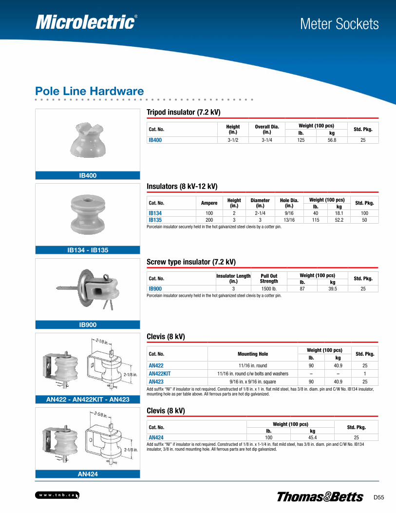
w w w . t n b . c a D55
IB400
IB134 - IB135
IB900
AN422 - AN422KIT - AN423
AN424
Tripod insulator (7.2 kV)
Cat. No. Height(in.)
Overall Dia. (in.)
Weight (100 pcs)Std. Pkg.
lb. kgIB400 3-1/2 3-1/4 125 56.8 25
Insulators (8 kV-12 kV)
Cat. No. Ampere Height(in.)
Diameter (in.)
Hole Dia.(in.)
Weight (100 pcs)Std. Pkg.
lb. kgIB134 100 2 2-1/4 9/16 40 18.1 100IB135 200 3 3 13/16 115 52.2 50
Porcelain insulator securely held in the hot galvanized steel clevis by a cotter pin.
Screw type insulator (7.2 kV)
Cat. No. Insulator Length (in.)
Pull OutStrength
Weight (100 pcs)Std. Pkg.
lb. kgIB900 3 1500 lb. 87 39.5 25
Porcelain insulator securely held in the hot galvanized steel clevis by a cotter pin.
Clevis (8 kV)
Cat. No. Mounting HoleWeight (100 pcs)
Std. Pkg.lb. kg
AN422 11/16 in. round 90 40.9 25
AN422KIT 11/16 in. round c/w bolts and washers – – 1
AN423 9/16 in. x 9/16 in. square 90 40.9 25Add suffix “NI” if insulator is not required. Constructed of 1/8 in. x 1 in. flat mild steel, has 3/8 in. diam. pin and C/W No. IB134 insulator, mounting hole as per table above. All ferrous parts are hot dip galvanized.
Clevis (8 kV)
Cat. No.Weight (100 pcs)
Std. Pkg.lb. kg
AN424 100 45.4 25Add suffix “NI” if insulator is not required. Constructed of 1/8 in. x 1-1/4 in. flat mild steel, has 3/8 in. diam. pin and C/W No. IB134 insulator, 3/8 in. round mounting hole. All ferrous parts are hot dip galvanized.
Meter Sockets
Pole Line Hardware
2-1/8 in.
2-1/8 in.
2-1/8 in.
2-5/8 in.
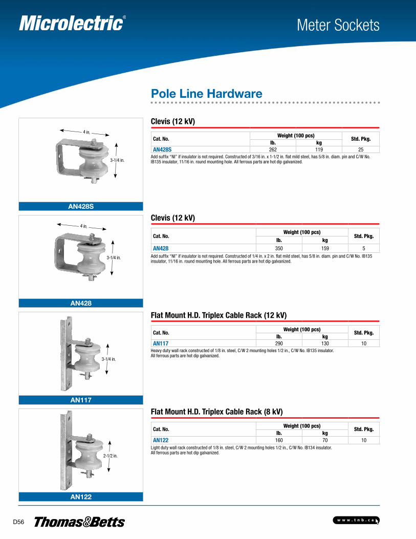
w w w . t n b . c aD56
AN428S
AN428
AN117
AN122
Meter Sockets
3-1/4 in.
4 in.
Clevis (12 kV)
Cat. No.Weight (100 pcs)
Std. Pkg.lb. kg
AN428S 262 119 25Add suffix “NI” if insulator is not required. Constructed of 3/16 in. x 1-1/2 in. flat mild steel, has 5/8 in. diam. pin and C/W No. IB135 insulator, 11/16 in. round mounting hole. All ferrous parts are hot dip galvanized.
Clevis (12 kV)
Cat. No.Weight (100 pcs)
Std. Pkg.lb. kg
AN428 350 159 5Add suffix “NI” if insulator is not required. Constructed of 1/4 in. x 2 in. flat mild steel, has 5/8 in. diam. pin and C/W No. IB135 insulator, 11/16 in. round mounting hole. All ferrous parts are hot dip galvanized.
Flat Mount H.D. Triplex Cable Rack (12 kV)
Cat. No.Weight (100 pcs)
Std. Pkg.lb. kg
AN117 290 130 10Heavy duty wall rack constructed of 1/8 in. steel, C/W 2 mounting holes 1/2 in., C/W No. IB135 insulator. All ferrous parts are hot dip galvanized.
Flat Mount H.D. Triplex Cable Rack (8 kV)
Cat. No.Weight (100 pcs)
Std. Pkg.lb. kg
AN122 160 70 10Light duty wall rack constructed of 1/8 in. steel, C/W 2 mounting holes 1/2 in., C/W No. IB134 insulator. All ferrous parts are hot dip galvanized.
Pole Line Hardware
3-1/4 in.
4 in.
3-1/4 in.
2-1/2 in.
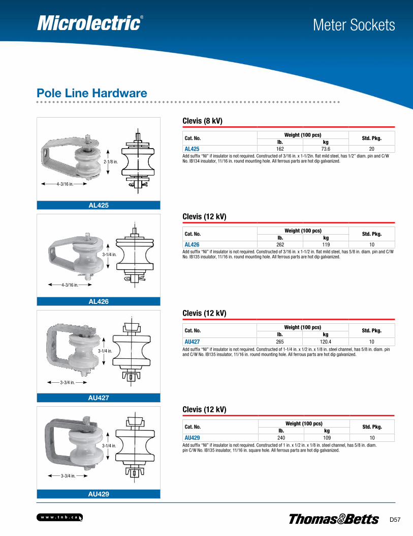
w w w . t n b . c a D57
AL425
AL426
AU427
AU429
Meter Sockets
Pole Line Hardware
2-1/8 in.
3-1/4 in.
4-3/16 in.
4-3/16 in.
3-1/4 in.
3-1/4 in.
3-3/4 in.
3-3/4 in.
Clevis (8 kV)
Cat. No.Weight (100 pcs)
Std. Pkg.lb. kg
AL425 162 73.6 20Add suffix “NI” if insulator is not required. Constructed of 3/16 in. x 1-1/2in. flat mild steel, has 1/2” diam. pin and C/W No. IB134 insulator, 11/16 in. round mounting hole. All ferrous parts are hot dip galvanized.
Clevis (12 kV)
Cat. No.Weight (100 pcs)
Std. Pkg.lb. kg
AL426 262 119 10Add suffix “NI” if insulator is not required. Constructed of 3/16 in. x 1-1/2 in. flat mild steel, has 5/8 in. diam. pin and C/W No. IB135 insulator, 11/16 in. round mounting hole. All ferrous parts are hot dip galvanized.
Clevis (12 kV)
Cat. No.Weight (100 pcs)
Std. Pkg.lb. kg
AU427 265 120.4 10Add suffix “NI” if insulator is not required. Constructed of 1-1/4 in. x 1/2 in. x 1/8 in. steel channel, has 5/8 in. diam. pin and C/W No. IB135 insulator, 11/16 in. round mounting hole. All ferrous parts are hot dip galvanized.
Clevis (12 kV)
Cat. No.Weight (100 pcs)
Std. Pkg.lb. kg
AU429 240 109 10Add suffix “NI” if insulator is not required. Constructed of 1 in. x 1/2 in. x 1/8 in. steel channel, has 5/8 in. diam. pin C/W No. IB135 insulator, 11/16 in. square hole. All ferrous parts are hot dip galvanized.
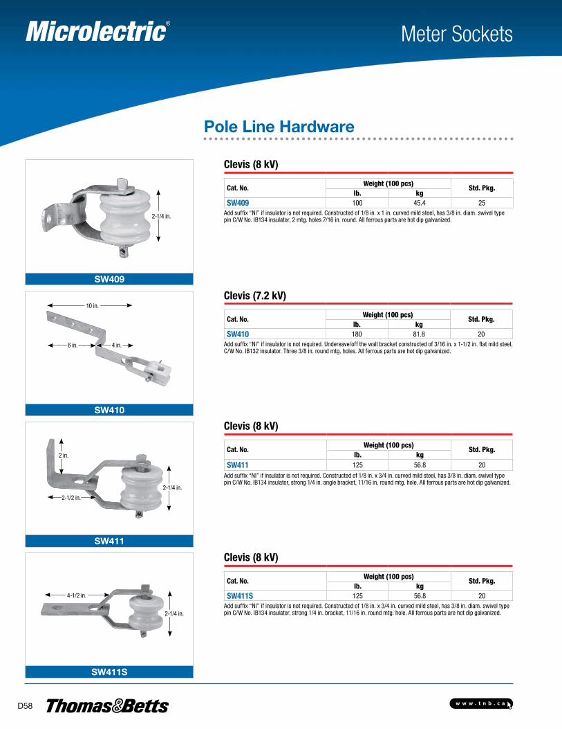
w w w . t n b . c aD58
SW409
SW410
SW411
SW411S
Meter Sockets
Pole Line Hardware
Clevis (8 kV)
Cat. No.Weight (100 pcs)
Std. Pkg.lb. kg
SW409 100 45.4 25Add suffix “NI” if insulator is not required. Constructed of 1/8 in. x 1 in. curved mild steel, has 3/8 in. diam. swivel type pin C/W No. IB134 insulator, 2 mtg. holes 7/16 in. round. All ferrous parts are hot dip galvanized.
Clevis (7.2 kV)
Cat. No.Weight (100 pcs)
Std. Pkg.lb. kg
SW410 180 81.8 20Add suffix “NI” if insulator is not required. Undereave/off the wall bracket constructed of 3/16 in. x 1-1/2 in. flat mild steel, C/W No. IB132 insulator. Three 3/8 in. round mtg. holes. All ferrous parts are hot dip galvanized.
Clevis (8 kV)
Cat. No.Weight (100 pcs)
Std. Pkg.lb. kg
SW411 125 56.8 20Add suffix “NI” if insulator is not required. Constructed of 1/8 in. x 3/4 in. curved mild steel, has 3/8 in. diam. swivel type pin C/W No. IB134 insulator, strong 1/4 in. angle bracket, 11/16 in. round mtg. hole. All ferrous parts are hot dip galvanized.
Clevis (8 kV)
Cat. No.Weight (100 pcs)
Std. Pkg.lb. kg
SW411S 125 56.8 20Add suffix “NI” if insulator is not required. Constructed of 1/8 in. x 3/4 in. curved mild steel, has 3/8 in. diam. swivel type pin C/W No. IB134 insulator, strong 1/4 in. bracket, 11/16 in. round mtg. hole. All ferrous parts are hot dip galvanized.
2-1/4 in.
2-1/4 in.
2-1/4 in.
2 in.
10 in.
6 in. 4 in.
2-1/2 in.
4-1/2 in.
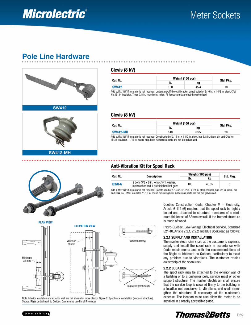
w w w . t n b . c a D59
SW412
SW412-MH
Meter Sockets
Pole Line Hardware
PLAN VIEWELEVATIoN VIEW
Bolt (mandatory)
Lag screw (prohibited)
Note: Interior insulation and exterior wall are not shown for more clarity. Figure 2: Spool rack installation (wooden structure). Source: Régie du bâtiment du Québec. Can also be used in all Provinces
Clevis (8 kV)
Cat. No.Weight (100 pcs)
Std. Pkg.lb. kg
SW412 100 45.4 10Add suffix “NI” if insulator is not required. Undereave/off the wall bracket constructed of 3/16 in. x 1-1/2 in. steel, C/W No. IB134 insulator. Three 3/8 in. round mtg. holes. All ferrous parts are hot dip galvanized.
Clevis (8 kV)
Cat. No.Weight (100 pcs)
Std. Pkg.lb. kg
SW412-MH 140 63.5 20Add suffix “NI” if insulator is not required. Constructed of 3/16 in. x 1-1/2 in. steel, has 5/8 in. diam. pin and C/W No. IB134 insulator. 11/16 in. round mtg. hole. All ferrous parts are hot dip galvanized.
Anti-Vibration Kit for Spool Rack
Cat. No. DescriptionWeight (100 pcs)
Std. Pkg.lb. kg
B3/8-6 2 bolts 3/8 x 6 in. long c/w 1 washer, 1 lockwasher and 1 nut finished hot galv. 100 45.35 5
Add suffix “NI” if insulator is not required. Constructed of 1-1/4 in. x 1/2 in. x 1/8 in. steel channel, has 5/8 in. diam. pin and C/W No. IB135 insulator, 11/16 in. round mounting hole. All ferrous parts are hot dip galvanized.
Minimum38 mm
Minimum38 mm
Québec Construction Code, Chapter V – Electricity, Article 6-112 (6) requires that the spool rack be tightly bolted and attached to structural members of a mini-mum thickness of 88mm overall, if the framed structure is made of wood.
Hydro-Québec, Low-Voltage Electrical Service, Standard E21-10, Article 2.2.1, 2.2.2 and Blue Book read as follows:
2.2.1 SUPPLY AND INSTALLATIoNThe master electrician shall, at the customer’s expense, supply and install the spool rack in accordance with Code requir ments and with the recommendations of the Régie du bâtiment du Québec, particularly to avoid any problem due to vibrations. The customer retains ownership of the spool rack.
2.2.2 LoCATIoNThe spool rack may be attached to the exterior wall of a building or to a customer pole, service mast or other support structure. The master electrician shall ensure that the service loop is secured firmly to the building in a location not conducive to vibrations, and shall stren-gthen the structure, if necessary, at the customer’s expense. The location must also allow the meter to be installed in a readily accessible place.
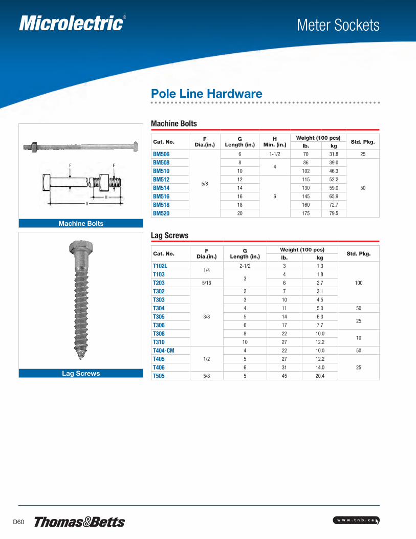
w w w . t n b . c aD60
GH
FF
Machine Bolts
Lag Screws
Meter Sockets
Pole Line Hardware
Machine Bolts
Cat. No. F Dia.(in.)
GLength (in.)
HMin. (in.)
Weight (100 pcs)Std. Pkg.
lb. kg
BM506
5/8
6 1-1/2 70 31.8 25
BM508 84
86 39.0
50
BM510 10 102 46.3
BM512 12
6
115 52.2
BM514 14 130 59.0
BM516 16 145 65.9
BM518 18 160 72.7
BM520 20 175 79.5
Lag Screws
Cat. No. F Dia.(in.)
GLength (in.)
Weight (100 pcs)Std. Pkg.
lb. kg
T102L1/4
2-1/2 3 1.3
100
T1033
4 1.8
T203 5/16 6 2.7
T302
3/8
2 7 3.1
T303 3 10 4.5
T304 4 11 5.0 50
T305 5 14 6.325
T306 6 17 7.7
T308 8 22 10.010
T310 10 27 12.2
T404-CM1/2
4 22 10.0 50
T405 5 27 12.2
25T406 6 31 14.0
T505 5/8 5 45 20.4
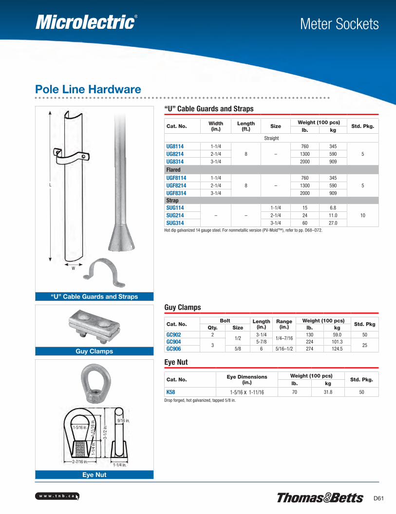
w w w . t n b . c a D61
“U” Cable Guards and Straps
Guy Clamps
Eye Nut
Meter Sockets
Pole Line Hardware
“U” Cable Guards and Straps
Cat. No. Width (in.)
Length(ft.) Size
Weight (100 pcs)Std. Pkg.
lb. kg
Straight
UG8114 1-1/4
8 –
760 345
5UG8214 2-1/4 1300 590
UG8314 3-1/4 2000 909
FlaredUGF8114 1-1/4
8 –
760 345
5UGF8214 2-1/4 1300 590
UGF8314 3-1/4 2000 909
StrapSUG114
– –
1-1/4 15 6.8
10SUG214 2-1/4 24 11.0
SUG314 3-1/4 60 27.0Hot dip galvanized 14 gauge steel. For nonmetallic version (PV-Mold™), refer to pp. D68–D72.
Guy Clamps
Cat. No.Bolt Length
(in.)Range
(in.)Weight (100 pcs)
Std. PkgQty. Size lb. kg
GC902 21/2
3-1/41/4–7/16
130 59.0 50GC904
35-7/8 224 101.3
25GC906 5/8 6 5/16–1/2 274 124.5
Eye Nut
Cat. No. Eye Dimensions(in.)
Weight (100 pcs)Std. Pkg.
lb. kg
K58 1-5/16 x 1-11/16 70 31.8 50
Drop forged, hot galvanized, tapped 5/8 in.
2-7/16 in.
9/16 in.
1-5/16 in.
1-1/
4 in
.
1-1/4 in.
1-11
/16
in.
3-1/
2 in
.
W
L
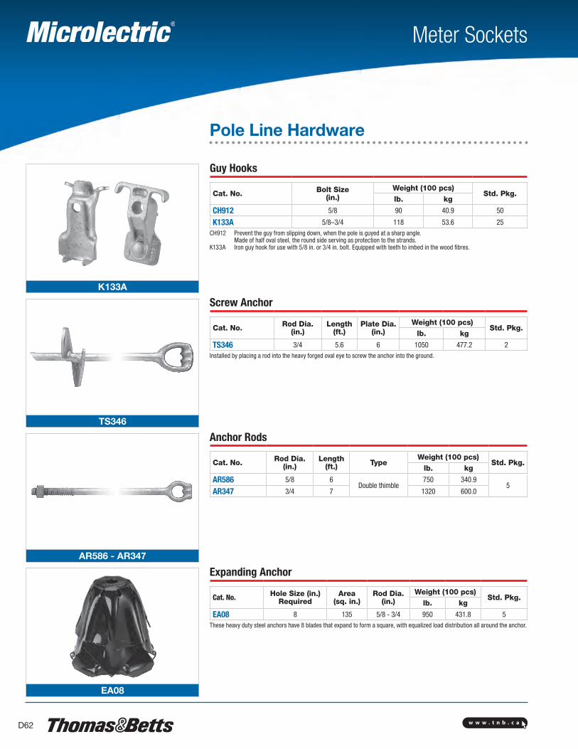
w w w . t n b . c aD62
K133A
TS346
AR586 - AR347
EA08
Meter Sockets
Pole Line Hardware
Guy Hooks
Cat. No. Bolt Size(in.)
Weight (100 pcs)Std. Pkg.
lb. kg
CH912 5/8 90 40.9 50
K133A 5/8–3/4 118 53.6 25CH912 Prevent the guy from slipping down, when the pole is guyed at a sharp angle. Made of half oval steel, the round side serving as protection to the strands.K133A Iron guy hook for use with 5/8 in. or 3/4 in. bolt. Equipped with teeth to imbed in the wood fibres.
Screw Anchor
Cat. No. Rod Dia.(in.)
Length(ft.)
Plate Dia.(in.)
Weight (100 pcs)Std. Pkg.
lb. kg
TS346 3/4 5.6 6 1050 477.2 2Installed by placing a rod into the heavy forged oval eye to screw the anchor into the ground.
Anchor Rods
Cat. No. Rod Dia.(in.)
Length(ft.) Type
Weight (100 pcs)Std. Pkg.
lb. kg
AR586 5/8 6Double thimble
750 340.95
AR347 3/4 7 1320 600.0
Expanding Anchor
Cat. No. Hole Size (in.)Required
Area(sq. in.)
Rod Dia. (in.)
Weight (100 pcs)Std. Pkg.
lb. kg
EA08 8 135 5/8 - 3/4 950 431.8 5These heavy duty steel anchors have 8 blades that expand to form a square, with equalized load distribution all around the anchor.
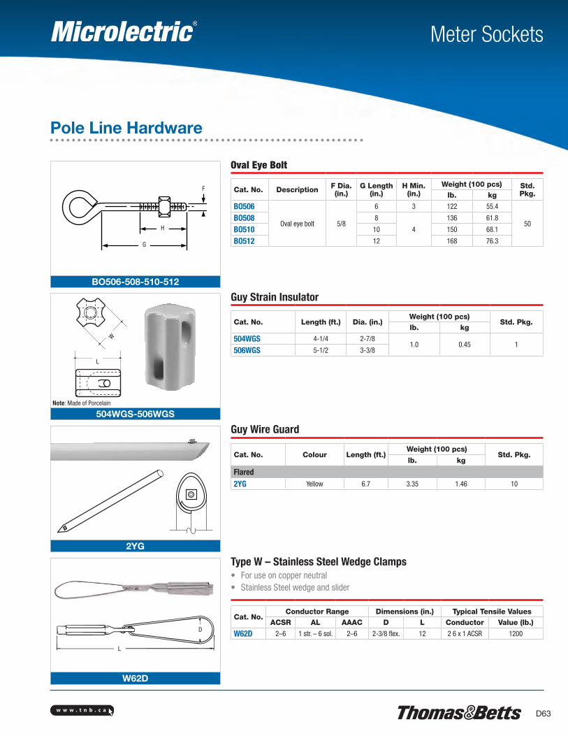
w w w . t n b . c a D63
BO506-508-510-512
504WGS-506WGS
2YG
D
L
W62D
G
H
F
L
W
D
L
Meter Sockets
Pole Line Hardware
Oval Eye Bolt
Cat. No. Description F Dia.(in.)
G Length (in.)
H Min.(in.)
Weight (100 pcs) Std. Pkg.lb. kg
BO506
Oval eye bolt 5/8
6 3 122 55.4
50BO508 8
4
136 61.8
BO510 10 150 68.1
BO512 12 168 76.3
Guy Strain Insulator
Cat. No. Length (ft.) Dia. (in.)Weight (100 pcs)
Std. Pkg.lb. kg
504WGS 4-1/4 2-7/81.0 0.45 1
506WGS 5-1/2 3-3/8
Guy Wire Guard
Cat. No. Colour Length (ft.)Weight (100 pcs)
Std. Pkg.lb. kg
Flared2YG Yellow 6.7 3.35 1.46 10
Type W – Stainless Steel Wedge Clamps• For use on copper neutral• Stainless Steel wedge and slider
Cat. No.Conductor Range Dimensions (in.) Typical Tensile Values
ACSR AL AAAC D L Conductor Value (lb.)
W62D 2–6 1 str. – 6 sol. 2–6 2-3/8 flex. 12 2 6 x 1 ACSR 1200
Note: Made of Porcelain
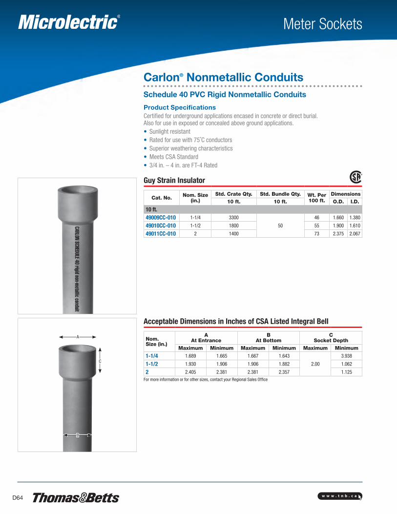
w w w . t n b . c aD64
B
A
C
Meter Sockets
Carlon® Nonmetallic ConduitsSchedule 40 PVC Rigid Nonmetallic Conduits
Product Specifications Certified for underground applications encased in concrete or direct burial. Also for use in exposed or concealed above ground applications.• Sunlight resistant• Rated for use with 75˚C conductors• Superior weathering characteristics• Meets CSA Standard• 3/4 in. – 4 in. are FT-4 Rated
Guy Strain Insulator
Cat. No. Nom. Size(in.)
Std. Crate Qty. Std. Bundle Qty. Wt. Per100 ft.
Dimensions10 ft. 10 ft. O.D. I.D.
10 ft.49009CC-010 1-1/4 3300
50
46 1.660 1.380
49010CC-010 1-1/2 1800 55 1.900 1.610
49011CC-010 2 1400 73 2.375 2.067
Acceptable Dimensions in Inches of CSA Listed Integral Bell
Nom. Size (in.)
A At Entrance
B At Bottom
C Socket Depth
Maximum Minimum Maximum Minimum Maximum Minimum
1-1/4 1.689 1.665 1.667 1.643
2.00
3.938
1-1/2 1.930 1.906 1.906 1.882 1.062
2 2.405 2.381 2.381 2.357 1.125For more information or for other sizes, contact your Regional Sales Office
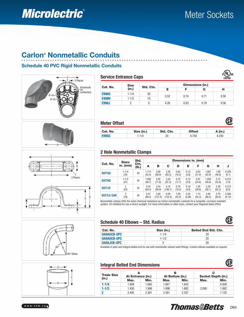
w w w . t n b . c a D65
Meter Sockets
Carlon® Nonmetallic ConduitsSchedule 40 PVC Rigid Nonmetallic Conduits
Service Entrance Caps
Cat. No. Size (in.) Std. Ctn.
Dimensions (in.)E F G H
E998G 1-1/4 203.52 0.74 0.71 0.50
E998H 1-1/2 10
E998J 2 5 4.26 0.83 0.78 0.56
Meter Offset
Cat. No. Size (in.) Std. Ctn. Offset A (in.)E995G 1-1/4 20 0.758 4.230
2 Hole Nonmetallic Clamps
Cat. No. Sizesin. (mm)
Std. Ctn. (lb.)
Dimensions in. (mm)
A B C D E F G H J
E977GC 1-1/4(35) 50 1.714
(43.5)2.68(68.0)
3.28(83.3)
0.64(16.2)
0.15(3.8)
0.83(21.0)
1.687(42.8)
1.89(48.0)
0.320(8.1)
E977HC 1-1/2(41) 50 1.920
(48.7)2.82(71.6)
3.44(87.3)
0.70(17.7)
0.15(3.8)
0.97(24.6)
1.930(49.0)
2.12(53.8)
0.312(7.9)
E977JC 2(53) 25 2.54
(64.5)3.54(89.9)
4.18(106.1)
0.76(19.3)
0.16(4.0)
1.05(26.6)
2.29(58.1)
2.49(63.2)
0.315(8.0)
E977LC-CAR 3(78) 20 3.47
(88.2)5.00
(127.0)6.00
(152.4)1.00(25.4)
0.20(5.08)
1.74(44.3)
3.48(88.4)
3.70(94.0)
0.360(9.14)
Nonmetallic clamps offer the same chemical resistance as Carlon nonmetallic conduits for a complete, corrosion resistant system. UV inhibited for use in direct sunlight. For more information or other sizes, contact your Regional Sales Office
Schedule 40 Elbows – Std. Radius
Cat. No. Size (in.) Belled End Std. Ctn.UA9AGCB-UPC 1-1/4 20UA9AHCB-UPC 1-1/2 25UA9AJCB-UPC 2 20
Available in plain and integral belled end for use with nonmetallic solvent weld fittings. Custom elbows available on request.
Integral Belled End Dimensions
Trade Size (in.)
AAt Entrance (in.)
BAt Bottom (in.)
CSocket Depth (in.)
Max. Min. Max. Min. Max. Min.1-1/4 1.689 1.665 1.667 1.643
2.0000.938
1-1/2 1.930 1.906 1.906 1.882 1.0622 2.405 2.381 2.381 2.357 1.125
Ø «G»
Ø «H»
E
Knockouts for conductors
F 3 Places
E
B
C
D
J2 Places
HG
AF
90° Elbow
R90°
A
A
B
C
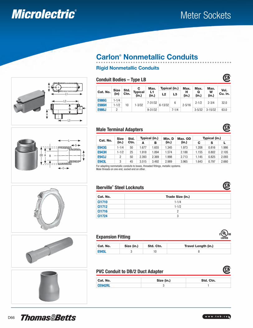
L1
Q
L2
H
L3
CW
OD A B
C
D
L
S
w w w . t n b . c aD66
Meter Sockets
Carlon® Nonmetallic ConduitsRigid Nonmetallic Conduits
Conduit Bodies – Type LB
Cat. No. Size (in)
Std. Ctn.
CTypical
(in.)
Max.L1 (in.)
Typical (in.) Max.H
(in.)
Max.Q
(in.)
Max.W
(in.)
Vol.Cu. in.L2 L3
E986G 1-1/410 1-3/32
7-31/326-13/32
62-5/16
2-1/2 2-3/4 32.0E986H 1-1/2
E986J 2 9-31/32 7-1/4 3-5/32 3-15/32 63.0
Male Terminal Adapters
Cat. No. Size (in.)
Std. Ctn.
Typical (in.) Min. D (in.)
Max. OD (in.)
Typical (in.)A B C S L
E943G 1-1/4 50 1.677 1.655 1.345 1.973 1.208 0.816 1.986
E943H 1-1/2 25 1.918 1.894 1.574 2.188 1.155 0.802 2.105
E943J 2 50 2.393 2.369 1.998 2.713 1.145 0.825 2.093
E943L 3 45 3.515 3.492 2.989 3.965 1.643 0.797 2.660For adapting nonmetallic conduits to boxes, threaded fittings, metallic systems. Male threads on one end, socket end on other.
Iberville® Steel Locknuts
Cat. No. Trade Size (in.)
CI1710 1-1/4
CI1712 1-1/2
CI1716 2
CI1724 3
Expansion Fitting
Cat. No. Size (in.) Std. Ctn. Travel Length (in.)
E945L 3 10 8
PVC Conduit to DB/2 Duct Adapter
Cat. No. Size (in.) Std. Ctn.
CE942RL 3 1
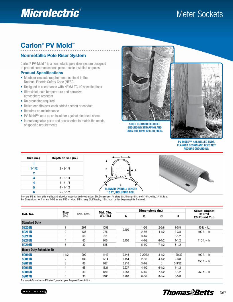
w w w . t n b . c a D67
Meter Sockets
Carlon® PV Mold™
Nonmetallic Pole Riser System
Steel U-GUard reqUireS GroUndinG StrappinG and
doeS not have belled endS.
pv-Mold™ haS belled endS, flanGed deSiGn and doeS not
reqUire GroUndinG.
Carlon® PV-Mold™ is a nonmetallic pole riser system designed to protect communications power cable installed on poles.Product Specifications• Meets or exceeds requirements outlined in the National Electric Safety Code (NESC)• Designed in accordance with NEMA TC-19 specifications• Ultraviolet, cold temperature and corrosive
atmosphere resistant• No grounding required• Belled end fits over each added section or conduit• Requires no maintenance• PV-Mold™ acts as an insulator against electrical shock• Interchangeable parts and accessories to match the needs
of specific requirements
Cat. No. Size(in.) Std. Ctn. Std. Ctn.
Wt. (lb.)
Dimensions (in.) Actual Impact @ 0 oC
20 Pound TupA B C H
Standard duty59208n 1 294 1059
0.1001-5/8 2-3/8 1-5/8 40 ft. – lb.
59211n 2 136 726 2-3/8 4-1/2 2-3/8 100 ft. – lb.
59213n 3 66 7610.150
3-1/2 6 3-1/2110 ft. – lb.59215n 4 65 910 4-1/2 6-1/2 4-1/2
59216n 5 30 515 5-1/2 7-1/2 5-1/2
heavy duty Schedule 4059010n 1-1/2 200 1142 0.145 2-29/32 3-1/2 1-29/32 100 ft. – lb.
59011n 2 136 1214 0.154 2-3/8 4-1/2 2-3/8150 ft. – lb.
59013n 3 66 937 0.216 3-1/2 6 3-9/32
59015n 4 65 1621 0.237 4-1/2 6-1/2 4-1/2260 ft. – lb.59016n 5 30 870 0.258 5-1/2 7-1/2 5-1/2
59017n 6 30 1160 0.280 6-5/8 8-3/4 6-5/8For more information on PV-Mold™, contact your Regional Sales Office.
Size (in.) Depth of Bell (in.) B
C
flanGed overall lenGth 10 ft., inclUdinG bell
HA
12 – 2-1/41-1/2
23 3 – 3-1/4
4 4 – 4-1/4
5 4 – 4-1/2
6 5 – 5-1/2Slots are 1/2 in. from side to side, and allow for expansion and contraction. Slot Dimensions: for sizes 2 in. through 6 in. are 5/16 in. wide, 3/4 in. long. Slot Dimensions: for 1 in. and 1-1/2 in. are 3/16 in. wide, 3/4 in. long. Slot Spacing: 18 in. from center, beginning 6 in. from end.

w w w . t n b . c aD68
A
B
DC D
A
B
C
A
E
D
BC
A
E
D
BC
E938JR E938NT E938NRR E938PRR
B
DC
A
B
A
D C
E939JN E939NR
A
C
B
E
E939NRT
Meter Sockets
Carlon® PV Mold™
PV-Mold™ Installation and FittingsPolyethylene Vented Boots and Adapters Note:1. A field cut may be needed to accommodate different boot or adapter to
Carlon® U-Mold size combinations.2. Recommendation: 2 sets of mounting holes per boot/fitting. To add mounting holes,
use a 3/8 in. drill bit and drill out where needed.3. When 3 in. or smaller conduit is being used, it’s recommended that the bottom
(largest section) of the boot or adapter section be buried 2 in. to 3 in. below ground surface.
Vented Boots
Cat. No. Size (in.)
Dimensions (in.)Std. Ctn. Std. Ctn.
Wt. (lb.)A B C D EE938JR 2 x 6 20.50 4.80 6.13 6.20 – 4 13.5
E938NT 4 x 8 21.00 15.00 11.34 9.76 – 4 21.0
E938NRR 4 x 6 20.87 16.57 12.87 11.68 11.43 6 26.4
E938PRR 5 x 6 16.74 3.65 10.84 11.43 – 6 23.2
Adapters
Cat. No. Size (in.)
Dimensions (in.)Std. Ctn. Std. Ctn.
Wt. (lb.)A B C DE939JN 2 x 4 11.00 6.75 5.88 5.07 8 10.0
E939NR 4 x 6 11.00 6.75 7.08 7.13 6 11.7
Cat. No. Size (in.)
Dimensions (in.)Std. Ctn. Std. Ctn.
Wt. (lb.)A B C D E
E939NRT 4 x 6 19.75 4.25 12.50 8.50 7.40 63 14.0
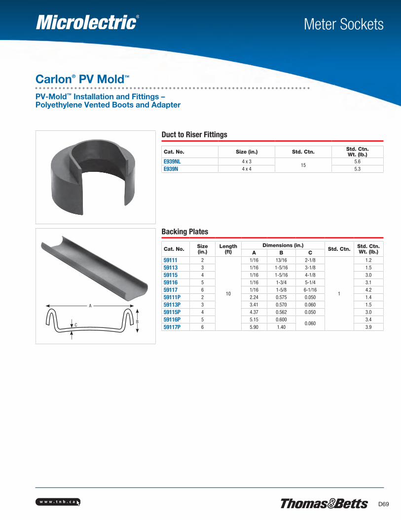
w w w . t n b . c a D69
A
BC
Meter Sockets
Carlon® PV Mold™
PV-Mold™ Installation and Fittings – Polyethylene Vented Boots and Adapter
Duct to Riser Fittings
Cat. No. Size (in.) Std. Ctn. Std. Ctn.Wt. (lb.)
E939NL 4 x 315
5.6
E939N 4 x 4 5.3
Backing Plates
Cat. No. Size (in.)
Length(ft)
Dimensions (in.)Std. Ctn. Std. Ctn.
Wt. (lb.)A B C59111 2
10
1/16 13/16 2-1/8
1
1.2
59113 3 1/16 1-5/16 3-1/8 1.5
59115 4 1/16 1-5/16 4-1/8 3.0
59116 5 1/16 1-3/4 5-1/4 3.1
59117 6 1/16 1-5/8 6-1/16 4.2
59111P 2 2.24 0.575 0.050 1.4
59113P 3 3.41 0.570 0.060 1.5
59115P 4 4.37 0.562 0.050 3.0
59116P 5 5.15 0.6000.060
3.4
59117P 6 5.90 1.40 3.9
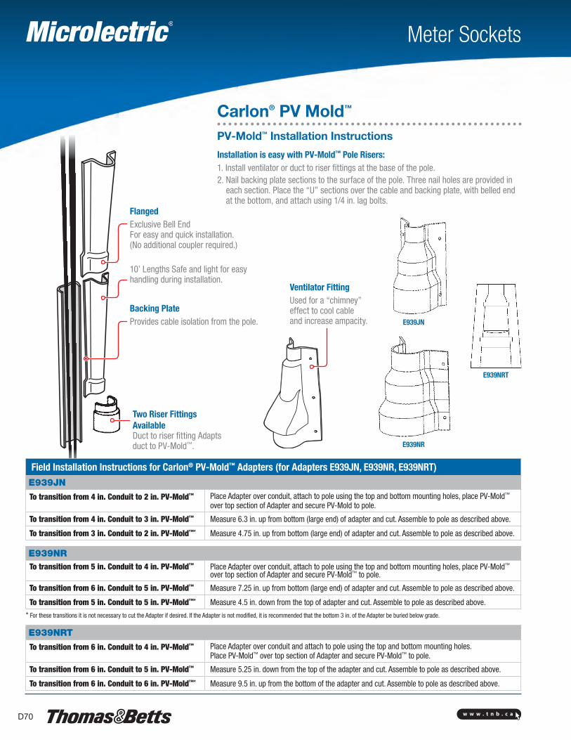
w w w . t n b . c aD70
E939JN
E939NR
E939NRT
Meter Sockets
Carlon® PV Mold™
PV-Mold™ Installation Instructions
Installation is easy with PV-Mold™ Pole Risers:1. Install ventilator or duct to riser fittings at the base of the pole.2. Nail backing plate sections to the surface of the pole. Three nail holes are provided in
each section. Place the “U” sections over the cable and backing plate, with belled end at the bottom, and attach using 1/4 in. lag bolts.
FlangedExclusive Bell End For easy and quick installation. (No additional coupler required.)
10’ Lengths Safe and light for easy handling during installation.
Backing PlateProvides cable isolation from the pole.
Ventilator FittingUsed for a “chimney” effect to cool cable and increase ampacity.
Field Installation Instructions for Carlon® PV-Mold™ Adapters (for Adapters E939JN, E939NR, E939NRT)E939JN
To transition from 4 in. Conduit to 2 in. PV-Mold™
Place Adapter over conduit, attach to pole using the top and bottom mounting holes, place PV-Mold™ over top section of Adapter and secure PV-Mold to pole.
To transition from 4 in. Conduit to 3 in. PV-Mold™ Measure 6.3 in. up from bottom (large end) of adapter and cut. Assemble to pole as described above.
To transition from 3 in. Conduit to 2 in. PV-Mold™* Measure 4.75 in. up from bottom (large end) of adapter and cut. Assemble to pole as described above.
E939NRTo transition from 5 in. Conduit to 4 in. PV-Mold™
Place Adapter over conduit, attach to pole using the top and bottom mounting holes, place PV-Mold™ over top section of Adapter and secure PV-Mold™ to pole.
To transition from 6 in. Conduit to 5 in. PV-Mold™ Measure 7.25 in. up from bottom (large end) of adapter and cut. Assemble to pole as described above.
To transition from 5 in. Conduit to 5 in. PV-Mold™* Measure 4.5 in. down from the top of adapter and cut. Assemble to pole as described above.
* For these transitions it is not necessary to cut the Adapter if desired. If the Adapter is not modified, it is recommended that the bottom 3 in. of the Adapter be buried below grade.
E939NRT
To transition from 6 in. Conduit to 4 in. PV-Mold™
Place Adapter over conduit and attach to pole using the top and bottom mounting holes. Place PV-Mold™ over top section of Adapter and secure PV-Mold™ to pole.
To transition from 6 in. Conduit to 5 in. PV-Mold™ Measure 5.25 in. down from the top of the adapter and cut. Assemble to pole as described above.
To transition from 6 in. Conduit to 6 in. PV-Mold™* Measure 9.5 in. up from the bottom of the adapter and cut. Assemble to pole as described above.
Two Riser Fittings AvailableDuct to riser fitting Adapts duct to PV-Mold™.
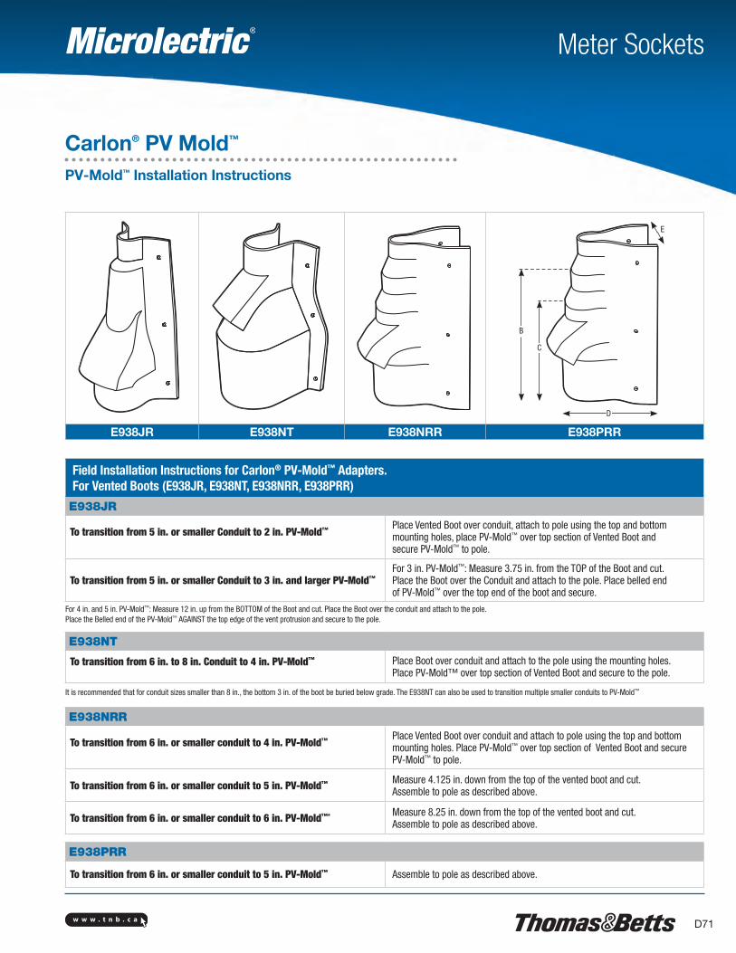
w w w . t n b . c a D71
C
B
D
E
E938JR E938NT E938NRR E938PRR
Meter Sockets
Carlon® PV Mold™
PV-Mold™ Installation Instructions
Field Installation Instructions for Carlon® PV-Mold™ Adapters. For Vented Boots (E938JR, E938NT, E938NRR, E938PRR)
E938JR
To transition from 5 in. or smaller Conduit to 2 in. PV-Mold™
Place Vented Boot over conduit, attach to pole using the top and bottom mounting holes, place PV-Mold™ over top section of Vented Boot and secure PV-Mold™ to pole.
To transition from 5 in. or smaller Conduit to 3 in. and larger PV-Mold™For 3 in. PV-Mold™: Measure 3.75 in. from the TOP of the Boot and cut. Place the Boot over the Conduit and attach to the pole. Place belled end of PV-Mold™ over the top end of the boot and secure.
For 4 in. and 5 in. PV-Mold™: Measure 12 in. up from the BOTTOM of the Boot and cut. Place the Boot over the conduit and attach to the pole. Place the Belled end of the PV-Mold™ AGAINST the top edge of the vent protrusion and secure to the pole.
E938NT
To transition from 6 in. to 8 in. Conduit to 4 in. PV-Mold™
Place Boot over conduit and attach to the pole using the mounting holes. Place PV-Mold™ over top section of Vented Boot and secure to the pole.
It is recommended that for conduit sizes smaller than 8 in., the bottom 3 in. of the boot be buried below grade. The E938NT can also be used to transition multiple smaller conduits to PV-Mold™
E938NRR
To transition from 6 in. or smaller conduit to 4 in. PV-Mold™
Place Vented Boot over conduit and attach to pole using the top and bottom mounting holes. Place PV-Mold™ over top section of Vented Boot and secure PV-Mold™ to pole.
To transition from 6 in. or smaller conduit to 5 in. PV-Mold™ Measure 4.125 in. down from the top of the vented boot and cut. Assemble to pole as described above.
To transition from 6 in. or smaller conduit to 6 in. PV-Mold™* Measure 8.25 in. down from the top of the vented boot and cut. Assemble to pole as described above.
E938PRR
To transition from 6 in. or smaller conduit to 5 in. PV-Mold™ Assemble to pole as described above.

w w w . t n b . c aD72
Waterpipe Ground Clamps
Cat. No.
Ground Wire Size Water Pipe Size
2-TB
#6, #4, #2 AWG
1/2 in., 3/4 in., 1 or rebar 4-10
3-TB 1-1/4 in., 1-1/2 in. or 2 in.
4 2-1/2 in., 3 in. or 3-1/2 in.
5-TB 4 in., 4-1/2 in. or 5 in.
6 6 in.Malleable iron crossbar, steel U-Bolt c/w copper cable clamp with serrations
Cat. No. Ground Wire Size Water Pipe Size
3902
#4–4/0 AWG
1/2 in.–1
3903 1-1/4 in.–2 in.
3904 2-1/2 in.–3-1/2 in.
3905-TB 4 in.–5 in.
3906-TB 6 in.
3907 8 in.
3908 10 in.
3909-TB 12 in.Material: Steel U-bolt and nut c/w bronzed aluminum cap and crossbar cadmium plated plus gold chromate finish
Cat. No. Ground Wire Size Water Pipe Size
3902BU*
#4–4/0 AWG
1/2 in.–1
3903BU* 1-1/4 in.–2 in.
3904BU* 2-1/2 in.–3-1/2 in.
3905BU* 4 in.–5 in.
3906BU* 6 in.
3907BU* 8 in.
3908BU* 10 in.
3909BU* 12 in.Material: Bronze U-bolt and nut c/w bronzed aluminum cap and crossbar with a brite dip finish. *UL Listed for Direct Burial
Meter Sockets
E-Z-Ground® Grounding Systems
Ground ClampsGround Clamps for K&L Grade Copper Tubing Only
Cat. No. Material Water Pipe, Copper Tubing Size
Ground Rod Size
3826* Malleable Iron1/2 in., 3/4 in. 1/2 in.–1
3846* Bronze
3849** Brass 1/2 in.–1–
3840-TB• Malleable Iron 1/2 in., 3/4 in. or 1* For unarmoured copper wires #6, #4 AWG. ** For copper and aluminum conductors; for #14 thru #2 AWG unarmoured copper wires for corrosive and outdoor use. UL approved for direct burial.• #8 thru #4 AWG. Not CSA Certified.
Cat. No. Ground Wire Size Water Pipe, Copper Tubing Size
3844*#8–#4 AWG
1/2 in.–1
3888** 1/2 in.–1 also rebar 4–10 * With Steel Screws. ** UL approved for direct burial. Silicon Bronze Screws
3844For armored and unarmoured wires.
38263849
3840-TB
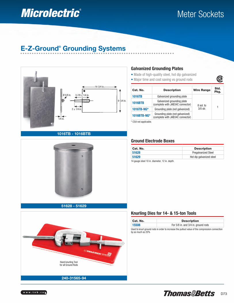
w w w . t n b . c a D73
Ø 5/8 in. 3-7/8 ± 1/4 in.
2 ± 1/4 in.
14-3/4 in.
1/4 in.
9-3/4 in.
1016TB - 1016BTB
51628 - 51629
Hand knurling Tool for all Ground Rods
240-31565-94
Meter Sockets
Galvanized Grounding Plates• Made of high-quality steel, hot dip galvanized• Major time and cost saving vs ground rods
Cat. No. Description Wire Range Std. Pkg.
1016TB Galvanized grounding plate
8 sol. to 3/0 str. 1
1016BTB Galvanized grounding plate(complete with JAB34C connector)
1016TB-NG* Grounding plate (not galvanized)
1016BTB-NG* Grounding plate (not galvanized)(complete with JAB34C connector)
* CSA not applicable.
E-Z-Ground® Grounding Systems
Ground Electrode Boxes
Cat. No. Description51628 Pregalvanized Steel
51629 Hot dip galvanized steel14 gauge steel 10 in. diameter, 12 in. depth.
Knurling Dies for 14- & 15-ton Tools
Cat. No. Description15508 For 5/8 in. and 3/4 in. ground rods
Used to knurl ground rods in order to increase the pullout value of the compression connection by as much as 20%
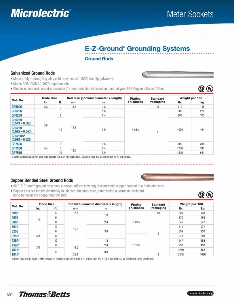
w w w . t n b . c aD74
Meter Sockets
Galvanized Ground Rods• Made of high-strength quality cold drawn steel, (1035) hot dip galvanized• Meets ANSI CI35.30-1979 requirements• Stainless steel rods are also available (for more detailed information, contact your T&B Regional Sales Office)
Cat. No.Trade Size Rod Size (nominal diameter x length) Plating
ThicknessStandard
PackagingWeight per 100
in. ft. mm m lb. kgGR5006 1/2
612.7 1.8
4 mils
10 410 186
GR6256
5/815.8
1.8
5
600 272
GR6258 8 2.4 800 363
GR6250(0.543 – 0.555)
10 3.0 1000 454GR6260(0.625 – 0.640)GR6250B*(0.618 – 0.623)GR7506
3/46 1.8 700 318
GR7508 819.0
2.4 1200 545
GR7510 10 3.0 1500 681* B suffix denotes black iron bare steel ground rod (CSA not applicable). CSA lists rods 1/2 in. and larger, 10 ft. and longer.
Copper Bonded Steel Ground Rods• All E-Z-Ground® ground rods have a heavy uniform covering of electrolytic copper bonded to a rigid steel core• Copper ions are forced electrically to join with the steel core, establishing a corrosion-resistant
bond between the copper and the steel
Cat. No.Trade Size Rod Size (nominal diameter x length) Plating
ThicknessStandard
PackagingWeight per 100
in. ft. mm m lb. kg
5005
1/2
5 12.71.8
5 mils
10 305 138
5006 6
15.8
5
370 168
5008 8 2.4 545 247
5010 10
3.0
611 277
62565/8
6 508 230
6258* 8
10 mils
678 308
6260* 10 1.8 847 384
7508*3/4
819.0
2.4 992 450
7510*10 3.0
1240 462
1010* 1 25.4 1 2248 1020* Ground rods are UL listed (425H), except for regular rods shorter than 8 ft. or less than 1/2 in. CSA lists rods 1/2 in. and larger, 10 ft. and longer.
E-Z-Ground® Grounding SystemsGround Rods
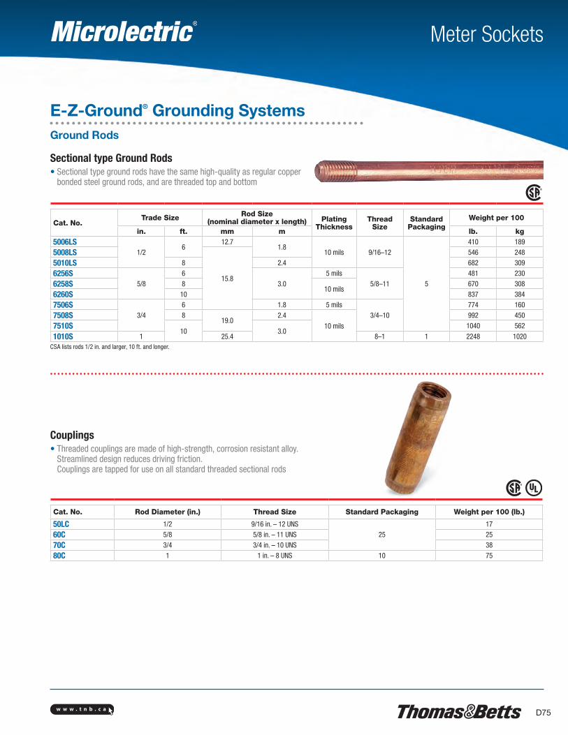
w w w . t n b . c a D75
Meter Sockets
E-Z-Ground® Grounding SystemsGround Rods
Sectional type Ground Rods• Sectional type ground rods have the same high-quality as regular copper
bonded steel ground rods, and are threaded top and bottom
Cat. No.Trade Size Rod Size
(nominal diameter x length) PlatingThickness
ThreadSize
Standard Packaging
Weight per 100
in. ft. mm m lb. kg5006LS
1/26
12.71.8
10 mils 9/16–12
5
410 189
5008LS
15.8
546 248
5010LS 8 2.4 682 309
6256S5/8
63.0
5 mils5/8–11
481 230
6258S 810 mils
670 308
6260S 10 837 384
7506S3/4
6 1.8 5 mils3/4–10
774 160
7508S 819.0
2.4
10 mils
992 450
7510S10 3.0
1040 562
1010S 1 25.4 8–1 1 2248 1020CSA lists rods 1/2 in. and larger, 10 ft. and longer.
Couplings• Threaded couplings are made of high-strength, corrosion resistant alloy.
Streamlined design reduces driving friction. Couplings are tapped for use on all standard threaded sectional rods
Cat. No. Rod Diameter (in.) Thread Size Standard Packaging Weight per 100 (lb.)
50LC 1/2 9/16 in. – 12 UNS25
17
60C 5/8 5/8 in. – 11 UNS 25
70C 3/4 3/4 in. – 10 UNS 38
80C 1 1 in. – 8 UNS 10 75
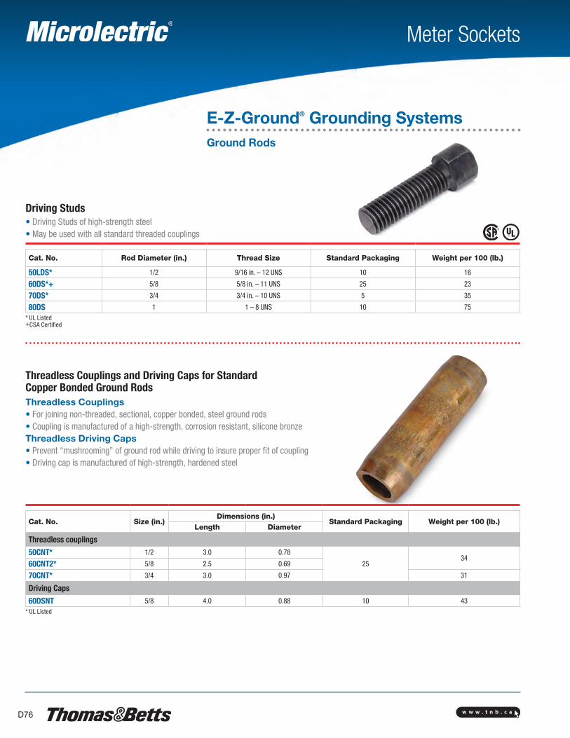
w w w . t n b . c aD76
Meter Sockets
E-Z-Ground® Grounding SystemsGround Rods
Driving Studs• Driving Studs of high-strength steel• May be used with all standard threaded couplings
Cat. No. Rod Diameter (in.) Thread Size Standard Packaging Weight per 100 (lb.)
50LDS* 1/2 9/16 in. – 12 UNS 10 16
60DS*+ 5/8 5/8 in. – 11 UNS 25 23
70DS* 3/4 3/4 in. – 10 UNS 5 35
80DS 1 1 – 8 UNS 10 75* UL Listed +CSA Certified
Threadless Couplings and Driving Caps for Standard Copper Bonded Ground RodsThreadless Couplings• For joining non-threaded, sectional, copper bonded, steel ground rods• Coupling is manufactured of a high-strength, corrosion resistant, silicone bronzeThreadless Driving Caps• Prevent “mushrooming” of ground rod while driving to insure proper fit of coupling• Driving cap is manufactured of high-strength, hardened steel
Cat. No. Size (in.)Dimensions (in.)
Standard Packaging Weight per 100 (lb.)Length Diameter
Threadless couplings
50CNT* 1/2 3.0 0.78
2534
60CNT2* 5/8 2.5 0.69
70CNT* 3/4 3.0 0.97 31
Driving Caps
60DSNT 5/8 4.0 0.88 10 43* UL Listed
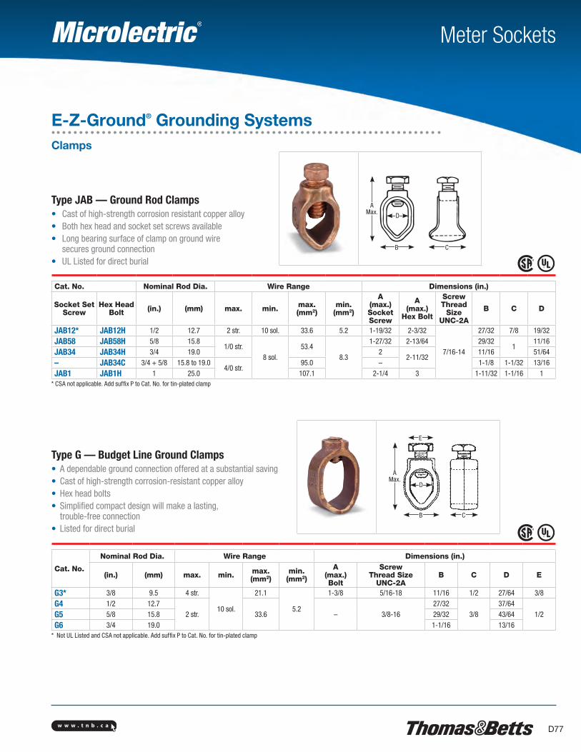
w w w . t n b . c a D77
CB
D
AMax.
Meter Sockets
E-Z-Ground® Grounding SystemsClamps
Type JAB — Ground Rod Clamps• Cast of high-strength corrosion resistant copper alloy• Both hex head and socket set screws available• Long bearing surface of clamp on ground wire
secures ground connection• UL Listed for direct burial
Cat. No. Nominal Rod Dia. Wire Range Dimensions (in.)
Socket Set Screw
Hex HeadBolt (in.) (mm) max. min. max.
(mm2)min.
(mm2)
A(max.)Socket Screw
A(max.)
Hex Bolt
ScrewThread
Size UNC-2A
B C D
JAB12* JAB12H 1/2 12.7 2 str. 10 sol. 33.6 5.2 1-19/32 2-3/32
7/16-14
27/32 7/8 19/32
JAB58 JAB58H 5/8 15.81/0 str.
8 sol.53.4
8.3
1-27/32 2-13/64 29/321
11/16
JAB34 JAB34H 3/4 19.0 22-11/32
11/16 51/64
– JAB34C 3/4 + 5/8 15.8 to 19.04/0 str.
95.0 – 1-1/8 1-1/32 13/16
JAB1 JAB1H 1 25.0 107.1 2-1/4 3 1-11/32 1-1/16 1* CSA not applicable. Add suffix P to Cat. No. for tin-plated clamp
Type G — Budget Line Ground Clamps• A dependable ground connection offered at a substantial saving• Cast of high-strength corrosion-resistant copper alloy• Hex head bolts• Simplified compact design will make a lasting,
trouble-free connection• Listed for direct burial
Cat. No.
Nominal Rod Dia. Wire Range Dimensions (in.)
(in.) (mm) max. min. max.(mm2)
min.(mm2)
A(max.)Bolt
ScrewThread Size
UNC-2AB C D E
G3* 3/8 9.5 4 str.
10 sol.
21.1
5.2
1-3/8 5/16-18 11/16 1/2 27/64 3/8
G4 1/2 12.72 str. 33.6 – 3/8-16
27/323/8
37/641/2G5 5/8 15.8 29/32 43/64
G6 3/4 19.0 1-1/16 13/16* Not UL Listed and CSA not applicable. Add suffix P to Cat. No. for tin-plated clamp
E
AMax.
D
B C
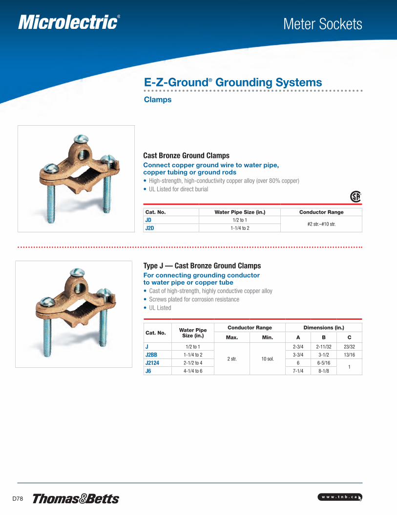
w w w . t n b . c aD78
Meter Sockets
E-Z-Ground® Grounding SystemsClamps
Cast Bronze Ground ClampsConnect copper ground wire to water pipe, copper tubing or ground rods• High-strength, high-conductivity copper alloy (over 80% copper)• UL Listed for direct burial
Cat. No. Water Pipe Size (in.) Conductor Range
JD 1/2 to 1#2 str.–#10 str.
J2D 1-1/4 to 2
Type J — Cast Bronze Ground ClampsFor connecting grounding conductor to water pipe or copper tube• Cast of high-strength, highly conductive copper alloy• Screws plated for corrosion resistance• UL Listed
Cat. No. Water PipeSize (in.)
Conductor Range Dimensions (in.)
Max. Min. A B C
J 1/2 to 1
2 str. 10 sol.
2-3/4 2-11/32 23/32
J2BB 1-1/4 to 2 3-3/4 3-1/2 13/16
J2124 2-1/2 to 4 6 6-5/161
J6 4-1/4 to 6 7-1/4 8-1/8
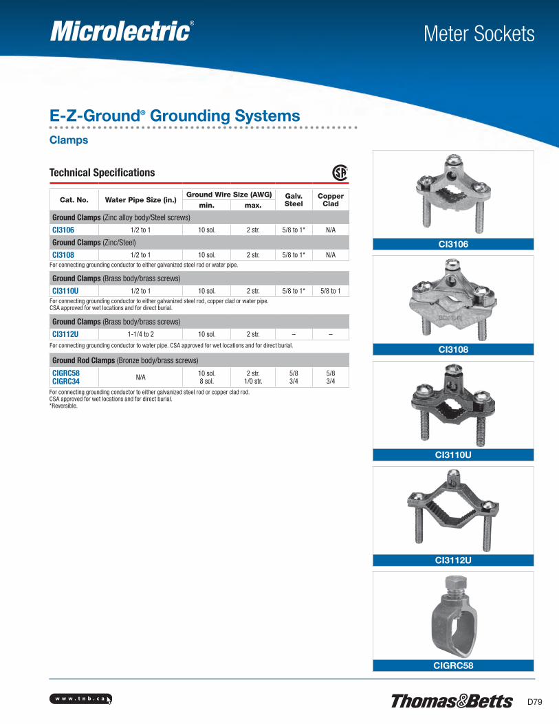
w w w . t n b . c a D79
CI3106
CI3108
CI3110U
CI3112U
CIGRC58
Meter Sockets
E-Z-Ground® Grounding SystemsClamps
Technical Specifications
Cat. No. Water Pipe Size (in.)Ground Wire Size (AWG) Galv.
SteelCopper
Cladmin. max.
Ground Clamps (Zinc alloy body/Steel screws)
CI3106 1/2 to 1 10 sol. 2 str. 5/8 to 1* N/A
Ground Clamps (Zinc/Steel)
CI3108 1/2 to 1 10 sol. 2 str. 5/8 to 1* N/AFor connecting grounding conductor to either galvanized steel rod or water pipe.
Ground Clamps (Brass body/brass screws)
CI3110U 1/2 to 1 10 sol. 2 str. 5/8 to 1* 5/8 to 1For connecting grounding conductor to either galvanized steel rod, copper clad or water pipe.CSA approved for wet locations and for direct burial.
Ground Clamps (Brass body/brass screws)
CI3112U 1-1/4 to 2 10 sol. 2 str. – –
For connecting grounding conductor to water pipe. CSA approved for wet locations and for direct burial.
Ground Rod Clamps (Bronze body/brass screws)
CIGRC58CIGRC34 N/A 10 sol.
8 sol.2 str.
1/0 str.5/83/4
5/83/4
For connecting grounding conductor to either galvanized steel rod or copper clad rod.CSA approved for wet locations and for direct burial. *Reversible.
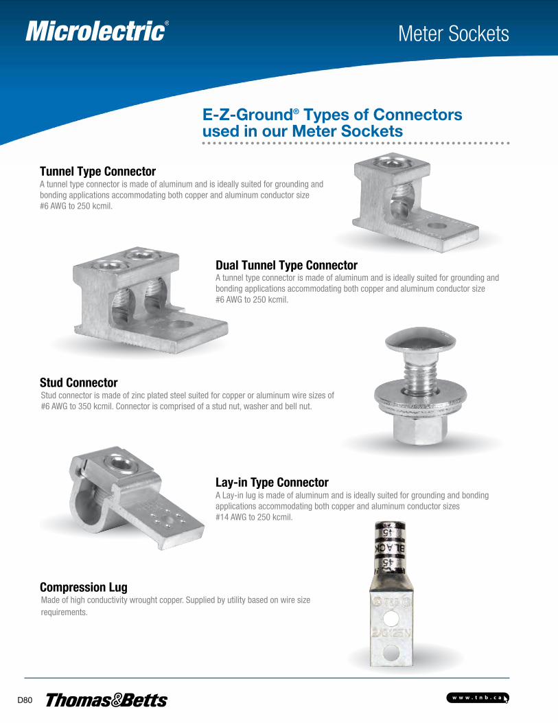
w w w . t n b . c aD80
Meter Sockets
A Lay-in lug is made of aluminum and is ideally suited for grounding and bonding applications accommodating both copper and aluminum conductor sizes #14 AWG to 250 kcmil.
Tunnel Type Connector
Dual Tunnel Type Connector
Stud connector is made of zinc plated steel suited for copper or aluminum wire sizes of#6 AWG to 350 kcmil. Connector is comprised of a stud nut, washer and bell nut.
Stud Connector
A tunnel type connector is made of aluminum and is ideally suited for grounding and bonding applications accommodating both copper and aluminum conductor size #6 AWG to 250 kcmil.
A tunnel type connector is made of aluminum and is ideally suited for grounding and bonding applications accommodating both copper and aluminum conductor size #6 AWG to 250 kcmil.
Lay-in Type Connector
Made of high conductivity wrought copper. Supplied by utility based on wire size requirements.
Compression Lug
E-Z-Ground® Types of Connectors used in our Meter Sockets

Head Office19295 25th AvenueSurrey, BC V3Z 3X1Tel: 778-545-9916Fax: 778-545-3099
Toll Free: 1-888-467-7626
Terrace5000 Pohle AvenueTerrace, BC V8G 4S8Tel: 250-635-6379
Prince George2255 S. Quinn StreetPrince George, BC V2N 2X4Tel: 250-563-0575
Kitimat622 Commercial AvenueKitimat, BC V8C 2C5Tel: 250-632-3774
Fort NelsonPO Box 3266 - 5016 48th AvenueFort Nelson, BC V0C 1R0Tel: 250-233-8570
Dawson Creek1101 97th AvenueDawson Creek, BC V1G 1N5Tel: 250-782-4896
Williams Lake527 S. MacKenzie AvenueWilliams Lake, BC V2G 1C8Tel: 250-392-7795
Vernon5203 24th StreetVernon, BC V1T 8X7Tel: 250-545-2191
Penticton401 Okanagan AvenuePenticton, BC V2A 3K1Tel: 250-492-4032
KamloopsB-983 Camosun CrescentKamloops, BC V2C 6G1Tel: 250-374-3191
CranbrookUnit A #800 Industrial Road. #2Cranbrook, BC V1C 4C9Tel: 250-489-4591
Parksville#105 - 425 E. Stanford AvenueParksville, BC V9P 2N4Tel: 250-954-1797
Duncan5286 Polkey RoadDuncan, BC V9L 6W3Tel: 250-748-3377
Courtenay2615 Moray PlaceCourtenay, BC V9N 8A9Tel: 250-334-0338
Campbell River1030 B - 9th AvenueCampbell River, BC V9W 4C2Tel: 250-287-9265
Surrey13055 80th AvenueSurrey, BC V3W 3B1Tel: 604-596-7111
Richmond12360 Vickers WayRichmond, BC V6V 1H9Tel: 604-273-1981
Langley#101 - 20550 Duncan WayLangley, BC V3A 7A3Tel: 604-533-1275
Burnaby3935 2nd AvenueBurnaby, BC V5C 3W9Tel: 604-292-4800
Lighting SpecialistTel: 778-545-9916
Projects GroupTel: 604-596-7111
Data Communications GroupTel: 778-545-9916
Process, Automation &Controls GroupTel: 778-545-9916
Unit 9, 7223 68 Avenue,Edmonton, Alberta T6B 3T6