Thermal chamber for adhesives creep testing machine
148
Thermal chamber for adhesives creep testing machine Manuel Brito Janeira Master Dissertation Supervisor: Prof. António Mendes Lopes Co-supervisor: Inv. Carlos Moreira da Silva Co-supervisor: Prof. Lucas F. M. da Silva Integrated Master in Mechanical Engineering January 2020
Transcript of Thermal chamber for adhesives creep testing machine
Thermal chamber for adhesives creep
testing machine
Manuel Brito Janeira
Master Dissertation
Supervisor: Prof. António Mendes Lopes
Co-supervisor: Inv. Carlos Moreira da Silva
Co-supervisor: Prof. Lucas F. M. da Silva
Integrated Master in Mechanical Engineering
January 2020

ii

iii
“Every chess master was once a beginner”
Irving Chernev

iv

v
Resumo
Os adesivos são cada vez mais utilizados num vasto leque de indústrias de ponta, devido
às suas excelentes propriedades, quando comparadas com métodos de ligação convencionais.
Assim, fabricantes e académicos estão empenhados em estudar estes materiais e as suas
caraterísticas.
O objetivo principal do Grupo de Adesivos (AJPU) da FEUP é estudar e avaliar
diferentes tipos de adesivos sujeitos a várias condições de trabalho. Um dos equipamentos
disponíveis no AJPU é uma máquina de ensaios à fluência com três postos de trabalho,
desenvolvida em Dissertações de Mestrado de Engenharia Mecânica realizadas em anos
anteriores. Os ensaios à fluência devem realizar-se a uma temperatura controlada, sendo assim
necessária a implementação de uma câmara térmica.
Com esta dissertação pretende desenvolver-se uma câmara térmica para a máquina de
ensaios à fluência já existente. A câmara tem de ser capaz de operar entre -100 e 200 e
apresentar baixo gradiente de temperaturas.
O primeiro passo foi conceber um isolador térmico para cada veio superior da máquina,
de modo a reduzir a temperatura nas células de carga para valores de serviço. O
desenvolvimento e validação do design do isolador térmico foi realizado recorrendo a
simulações numéricas no SolidWorks.
Posteriormente, o conceito da câmara foi desenvolvido, explorando diferentes soluções.
Quando conveniente, diferentes opções com influência na eficácia térmica da câmara foram
suportadas por explicações matemáticas. Ao mesmo tempo, os projetos de controlo e automação
necessários para o funcionamento da câmara foram desenvolvidos. Durante o processo de
desenvolvimento, os materiais e os componentes foram selecionados com base nas suas
propriedades, disponibilidade e preço.
Por fim, foram realizados os desenhos técnicos, definindo os materiais e as dimensões
dos componentes desenvolvidos.

vi
vii
Abstract
Adhesives have been increasingly used in a wide range of industries, due to their good
proprieties when compared with traditional joining methods. Therefore, manufacturers and
researchers have been making an effort to study these materials and their characteristics.
The main goal of the Adhesives Group (AJPU) of FEUP is to study and evaluate
different types of adhesives under different conditions. One equipment available at the AJPU
is a creep testing machine with three independent working stations, developed in the context of
previous Mechanical Engineering Master Dissertations. As the creep tests must be performed
under controlled temperature, the implementation of a thermal chamber was required.
The main goal of this masters’ dissertation is to design a thermal chamber for the
existing creep testing machine. The chamber needs to be capable of operating between -100
and 200 and have a low temperature gradient.
The first step was to design a heat insulator for each upper rod of the creep testing
machine, in order to limit the temperature at the load cells to service values. The development
and validation of the design were made using thermal simulations on SolidWorks.
Subsequently, the concept of the chamber was developed, exploring different possible
designs. When convenient, the solutions with influence on the thermal efficiency of the
chamber were supported analytically. The development of the chamber was made side by side
with the required control and automation project of the chamber. During this process, the
materials and the components were selected based on their proprieties, availability and market
price.
Finally, the technical drawings were defined and the materials were selected.

viii

ix
Acknowledgments
Firstly, I would like to thank my supervisors Prof. António Mendes Lopes, Inv. Carlos
Moreira da Silva and Prof. Lucas da Silva for all the support and knowledge they gave me
during the dissertation.
To Prof. Paulo Coelho and Mr. Joaquim Silva, for the availability and patience that was
fundamental to conclude all the work.
To my family, friends and especially to my girlfriend who during all my academic life
encouraged me to move forward and fight for my goals.
Finally, to all members of the AJPU for their help in every issue along this dissertation.

x

xi
Contents
1 Introduction ............................................................................................................................. 1
1.1 Background and motivations .................................................................................................. 1
1.2 Objectives .............................................................................................................................. 1
1.3 Methodology ........................................................................................................................... 2
1.4 Dissertation outline ................................................................................................................. 2
2 Literature review ..................................................................................................................... 4
2.1 Introduction to adhesives ....................................................................................................... 4
2.2 Creep testing machine ........................................................................................................... 5
2.2.1 The AJPU creep testing machine ........................................................................................... 6
2.2.2 Creep testing machines in the market .................................................................................... 8
2.3 Thermal chambers ................................................................................................................. 9
2.3.1 Heating system .................................................................................................................... 10
2.3.2 Colling system ...................................................................................................................... 11
2.3.3 Market solutions for thermal chambers ................................................................................ 12
2.4 Discussion ............................................................................................................................ 16
3 Thermal chamber design ..................................................................................................... 17
3.1 Heat transfer concepts and principles .................................................................................. 17
3.2 Thermal and dimensional restrictions for the chamber ......................................................... 19
3.3 Heat insulator ....................................................................................................................... 21
3.4 Structural design of the chamber ......................................................................................... 36
3.4.1 Chamber shells .................................................................................................................... 37
3.4.2 Insulations layers ................................................................................................................. 42
3.4.3 Front window ........................................................................................................................ 44
3.4.4 Connections between the thermal chamber and the creep testing machine ........................ 46
3.4.5 Back half .............................................................................................................................. 48
3.5 Discussion ............................................................................................................................ 50
4 Control and command .......................................................................................................... 51
4.1 Temperature control ............................................................................................................. 51
4.1.1 Heating control ..................................................................................................................... 54
4.1.2 Cooling control ..................................................................................................................... 55
4.2 Selection of the temperature controller ................................................................................ 56
4.2.1 Characteristics of OMRON temperature controllers ............................................................. 56
4.2.2 SSR precautions .................................................................................................................. 59
4.2.3 Selection of the OMRON controller ...................................................................................... 61
xii
4.3 Electronic components ......................................................................................................... 62
4.3.1 Temperature controller ......................................................................................................... 62
4.3.2 Temperature sensor ............................................................................................................. 63
4.3.3 SSR ………………………………………………………………………………………………….64
4.3.4 Heating elements and fan ..................................................................................................... 65
4.3.5 Cryogenic solenoid valve and cryogenic safety valve........................................................... 67
4.3.6 Fans ………………………………………………………………………………………………….68
4.3.7 Protective equipment ............................................................................................................ 69
4.3.8 Reed contact ........................................................................................................................ 69
4.3.9 Switches ............................................................................................................................... 69
4.3.10 Lights ........................................................................................................................... 70
4.4 Electric circuit ....................................................................................................................... 72
4.4.1 Power circuit ......................................................................................................................... 72
4.4.2 Command circuit................................................................................................................... 73
4.5 Discussions .......................................................................................................................... 74
5 Conclusions ..........................................................................................................................75
5.1 Conclusions .......................................................................................................................... 75
5.2 Future development .............................................................................................................. 76
6 References ...........................................................................................................................78
Appendix A: Table ................................................................................................................81
Appendix B: Technical drawing ............................................................................................85

xiii
List of Figures
Figure 1 – Strain versus time behavior during creep [8]. ........................................................... 5
Figure 2 – INSTRON model 3367 testing machine. .................................................................. 6
Figure 3 – INSTRON model 3119 environmental chamber....................................................... 6
Figure 4 – AJPU creep testing machine. .................................................................................... 7
Figure 5 – Creep test using hanging weights. ............................................................................. 7
Figure 6 – ZWICK’s multi-station creep testing machine [10]. ................................................. 8
Figure 7 – INSTRON’s multi-station creep testing machine [11].............................................. 9
Figure 8 – Scheme of the sandwich structure of a chamber. ...................................................... 9
Figure 9 – Examples of heating elements [18]. ........................................................................ 10
Figure 10 – Temperature versus time for different methods of cooling [21]. .......................... 12
Figure 11 – Example of creep testing machine with a thermal chamber by ZWICK [23]....... 13
Figure 12 – Example of two creep testing machines with thermal chambers from INSTRON
[16]. .......................................................................................................................................... 15
Figure 13 – Scheme of the airflow through the chamber [16].................................................. 15
Figure 14 – Scheme of the three modes of heat transfer [24]. ................................................. 17
Figure 15 – One-dimensional heat transfer by conduction [24]. .............................................. 18
Figure 16 – Scheme of heat transfer by convection [24]. ......................................................... 18
Figure 17 – Load cells from AEP transducers [25]. ................................................................. 20
Figure 18 – Example of a heat sink [3]. ................................................................................... 21
Figure 19 – Print screen from the QuickField tool [26]. .......................................................... 23
Figure 20 – Graphic of convection coefficient versus temperature.......................................... 23
Figure 21 – Heat sink. .............................................................................................................. 24
Figure 22 – Results of the thermal simulation with 20 fins, each one with 25 mm of width and
2 mm of thickness. .................................................................................................................... 24
Figure 23 – Results of the thermal simulation with 40 fins, each one with 25 mm of width and
2 mm of thickness. .................................................................................................................... 25
Figure 24 – Results of the thermal simulation with 40 fins, each one with 50 mm of width and
2 mm of thickness. .................................................................................................................... 25
Figure 25 – Results of the thermal simulation with 40 fins, each one with 60 mm of width and
1.5 mm of thickness. ................................................................................................................. 26
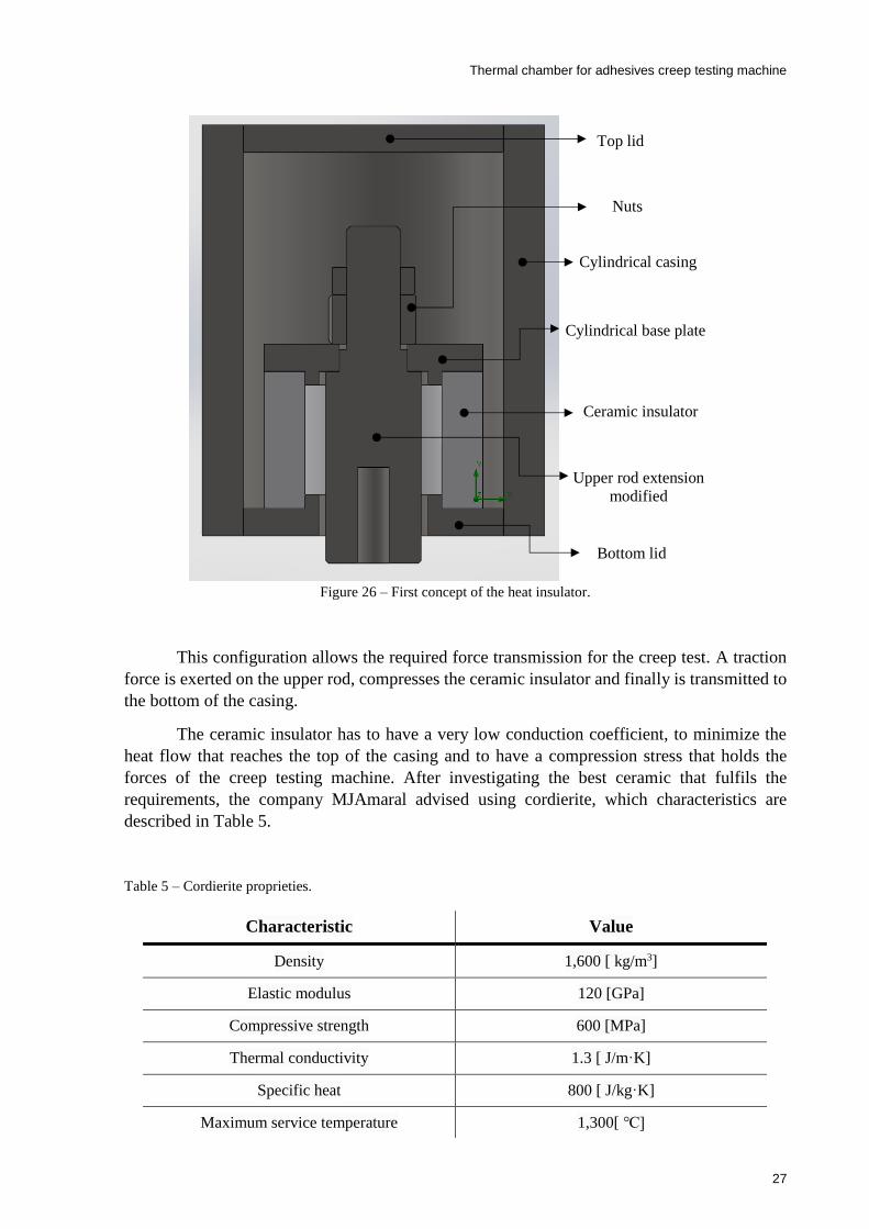
Figure 26 – First concept of the heat insulator. ........................................................................ 27

xiv
Figure 27 – Results of the thermal simulation made for the heat insulator’s initial design. .... 28
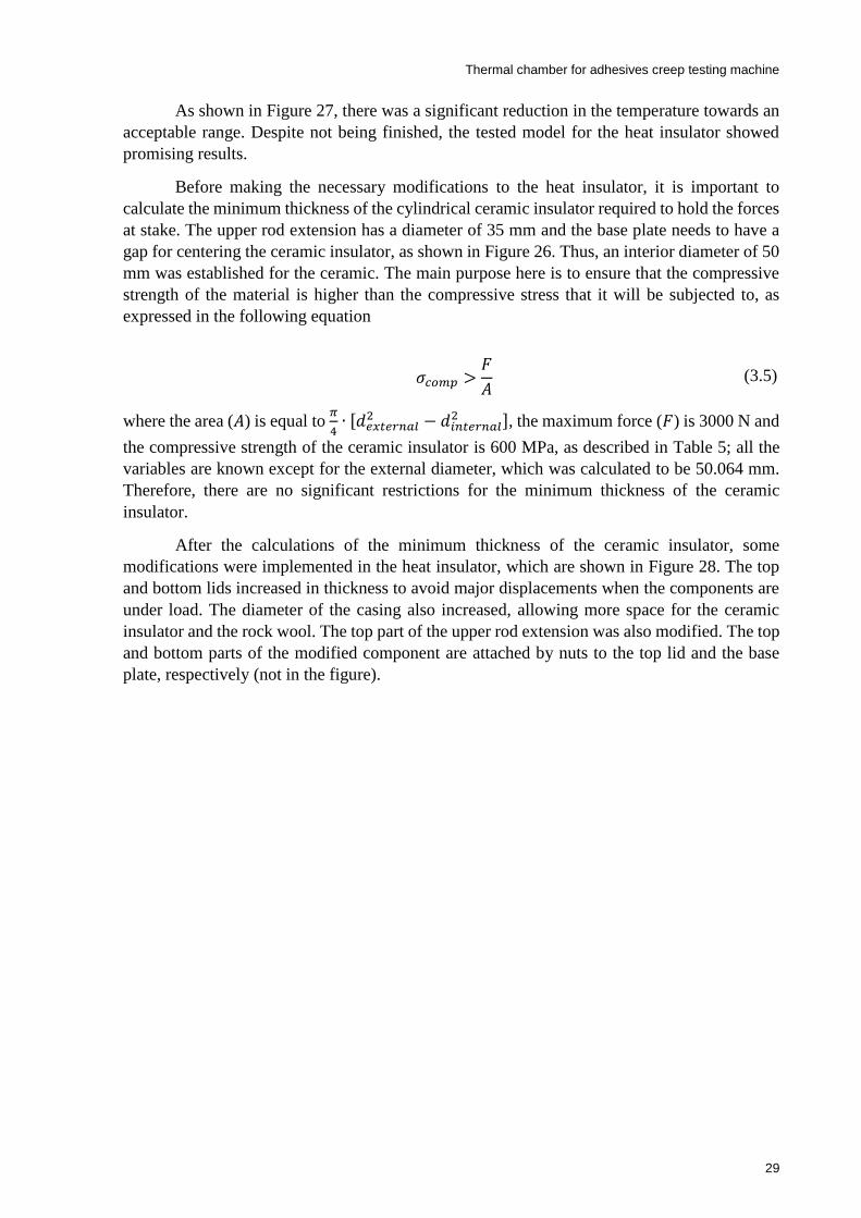
Figure 28 – Modified heat insulator. ........................................................................................ 30
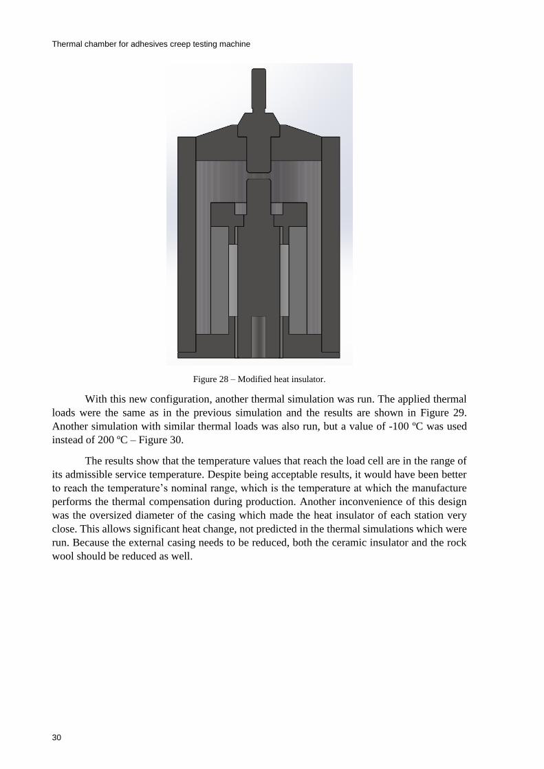
Figure 29 – Results of thermal simulation with a temperature load of 200. ........................ 31
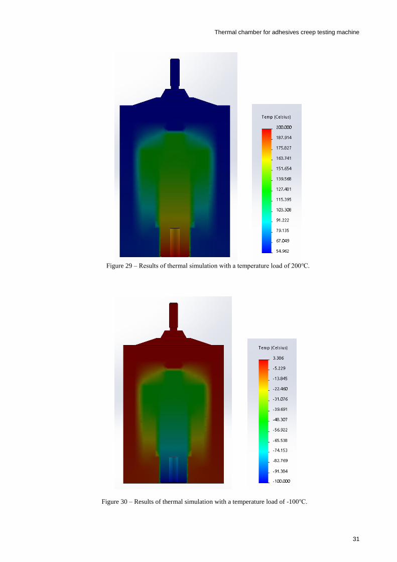
Figure 30 – Results of thermal simulation with a temperature load of -100. ...................... 31
Figure 31 – Heat insulator final design. ................................................................................... 32
Figure 32 – Thermal simulation for the final design of the heat insulator, with a temperature
load of 200. .......................................................................................................................... 33
Figure 33 – Thermal simulation for the final design of the heat insulator, with a temperature
load of -100. ......................................................................................................................... 34
Figure 34 – Stress results of the static load simulation. ........................................................... 35
Figure 35 – Displacement results of the static load simulation. .............................................. 35
Figure 36 – Exterior casing and lids. ....................................................................................... 37
Figure 37 – (a) Middle casing; (b) Section view of the exterior and middle casing forming the
insulation layer. ........................................................................................................................ 38
Figure 38 – (a) Middle shell; (b) Detail of the middle shell, where the slots for the air channels
were made. ............................................................................................................................... 38
Figure 39 – Internal shell. ........................................................................................................ 39
Figure 40 – The three structures assembled. ............................................................................ 39
Figure 41 – Exploded view of the assembly of the three shells. .............................................. 40
Figure 42 – Middles shell with the U structure profiles. ......................................................... 40
Figure 43 – Extra cuts made in the middle casing. .................................................................. 41
Figure 44 – Detail of the middle casing with the spacers glued. ............................................. 41
Figure 45 – Assembly of the chamber shell and the front frame components. ........................ 42
Figure 46 – Window hole for the front half of the chamber. ................................................... 44
Figure 47 – (a) Section view of the window; (b) Exploded view of the window. ................... 45
Figure 48 – Components responsible for the attachment between the chamber and the creep
testing machine. ....................................................................................................................... 46
Figure 49 – (a) Base plate screwed to the structural profile; (b) Scheme of the custom made
shaft. ......................................................................................................................................... 47
Figure 50 – Component of the crank. ...................................................................................... 47
Figure 51 – (a) Detail of the spacer; (b) exploded view of the spacer. .................................... 48
Figure 52 – Back panel. ........................................................................................................... 49
Figure 53 – Electrical enclosure............................................................................................... 49
Figure 54 – Scheme of the typical components of a temperature control system [27]. ........... 52

xv
Figure 55 – Different temperature responses of the controlled system [27]. ........................... 53
Figure 56 – Responses of the controlled system with different control actions [27]. .............. 53
Figure 57 – Configuration of a feedback control system [27]. ................................................. 54
Figure 58 – Temperature controller configuration [27]............................................................ 54
Figure 59 – Response to an ON/OFF control [31]. .................................................................. 55
Figure 60 – Scheme of the cooling method. ............................................................................. 56
Figure 61 – System response with one PID and two PID controllers [27]. .............................. 57
Figure 62 – Response with a time-proportional control [27]. .................................................. 58
Figure 63 – Circuit to eliminate the pulse noise at the input terminals of an SSR [34]. .......... 60
Figure 64 – Circuit to eliminate DC switching noise with inductive load [34]. ...................... 60
Figure 65 – Inrush current values compared with their normal current for different loads [34].
.................................................................................................................................................. 61
Figure 66 – Scheme of the command circuit. ........................................................................... 62
Figure 67 – Temperature controller from OMRON E5CC-T series [35]. ................................ 63
Figure 68 – Thermocouple type T [37]. ................................................................................... 64
Figure 69 – SSR from OMRON G3NA series [39]. ................................................................ 65
Figure 70 – Heating element from AEG [40]. .......................................................................... 65
Figure 71 – Motor and fan assembly from Belling [41]. .......................................................... 66
Figure 72 - Cryogenic solenoid valve [43]. .............................................................................. 67
Figure 73 – SUNON’s AC fan [45]. ......................................................................................... 68
Figure 74 – Two position switch [48]. ..................................................................................... 70
Figure 75 – Pushbutton. ............................................................................................................ 70
Figure 76 – RS Pro green indicator [49]................................................................................... 71
xvi
List of Tables
Table 1 – Application and sheath material of heating elements [20]. ...................................... 11
Table 2 – Characteristics of ZWICK’s thermal chambers [23]. .............................................. 14
Table 3 – Temperature values for the load cell [25]. ............................................................... 20
Table 4 – Characteristics values of stainless steel AISI 304 and aluminum 1060 alloy. ......... 22
Table 5 – Cordierite proprieties. .............................................................................................. 27
Table 6 – Rock wool proprieties. ............................................................................................. 28
Table 7 – Proprieties of the RTV silicon. ................................................................................ 41
Table 8 – Values of conductivity and convection coefficient. ................................................. 43
Table 9 – Parameter used to calculate the thermal resistances. ............................................... 46
Table 10 – Types of outputs. .................................................................................................... 58
Table 11 – Temperature ranges of thermocouples [36]. .......................................................... 63
Table 12 – Heating element characteristics [40]. ..................................................................... 66
Table 13 – Motor and fan assembly characteristics [41] [42]. ................................................. 66
Table 14 – Characteristics of the cryogenic solenoid valve [43]. ............................................ 67
Table 15 – Characteristics of the cryogenic safety valve [44]. ................................................ 68
Table 16 – Fan characteristics [46]. ......................................................................................... 68
Table 17 – RCBO characteristics [47]. .................................................................................... 69

xvii

xviii
Acronyms
AJPU – Advance Joining Processes Unit
AC – Alternating Current
CFM – Cubic Feet per Minute
DC – Direct Current
FEUP – Faculdade de Engenharia da Universidade do Porto
LED – Light Emitting Diode
RCBO – Residual Current circuit Breaker with Overcurrent protection
rpm – Rotations per Minute
RT – Room Temperature
SSR – Solid State Relay
UTM – Universal Test Machine

xix


Thermal chamber for adhesives creep testing machine
1
1 Introduction
1.1 Background and motivations
Adhesives have increasing importance in today’s industry, with a strong presence in the
aerospace, automotive, railway and marine industries, as well as in civil construction, electrical
equipment and even in medicine and dentistry areas.
The use of natural adhesive is very ancient, but just in recent years, the humankind
started to use adhesives based on synthetic polymers. The advantages of adhesive joints
compared to traditional mechanical joints led to an increase in the studies in this field [1].
At Faculdade de Engenharia da Universidade do Porto (FEUP), a research group
(Advance Joining Processes Unit - AJPU) was created to study the proprieties and behavior of
adhesives and adhesive joints, contributing with their research for the advance of the state-for-
the-art in the field. The AJPU is involved in different projects; therefore, the use of a large
variety of equipment is unceasing. An important equipment is the multi-station creep testing
machine. Being creep a typical characteristic of a material, adhesives included, its study and
understanding are fundamental. Due to the correlation between creep and temperature, studying
creep under different values of temperature is of paramount importance.
Freire [2], Pina [3] and Silva [4] developed the AJPU multi-station creep testing
machine. In their projects, the construction of a thermal chamber was mentioned, but it was
never developed.
1.2 Objectives
The main goal of this dissertation is to develop a thermal chamber that can operate
between -100 and 200 . The chamber has to be integrated with the existing multi-station
creep testing machine developed by Freire [2], Pina [3] and Silva [4].
Besides operating in a specified range of temperatures, the thermal chamber has to
ensure a low temperature gradient over its inner volume and to respect the dimensions imposed

Thermal chamber for adhesives creep testing machine
2
by the creep testing machine. It must also guarantee human safe values of on the exterior casing
and safe temperature values for all the components that constitute the equipment.
The chamber also needs to work autonomously, meaning that the temperature control
has to perform automatically over long periods of time, and the interface for setting up the
thermal tests should be user-friendly.
1.3 Methodology
Initially, a literature review on creep testing machines was done. For that propose, the
previous master dissertations of Freire [2], Pina [3] and Silva [4] were analyzed, books and
papers on the subject were read, and the state-of-the-art on such machines was revised.
After understanding the previous work and the solutions available on the market,
another literature review was done, now focused on thermal chambers. The principles of the
constructive solutions were understood, namely on how the insulation is made, how the heating
and cooling systems operate and what solutions for integrating thermal chambers in creep
testing machines exist in the market.
Then, the thermal and dimensional restrictions for the thermal chamber were established
and a heat insulator was designed. After performing thermal and static force simulations, the
solution was validated. Then, the design of the chamber was developed, having in mind the
thermal needs of the equipment.
Finally, the automation project was executed. All the required electric components were
selected, and the command and control circuits were established.
1.4 Dissertation outline
This dissertation is organized in six chapters, each one covering a subject of relevance
for the understanding of the content developed.
The first chapter gives a brief introduction to the dissertation, the background, the
motivation for the project and its main objectives.
In the second chapter, a small introduction to adhesives is made, followed by a literature
review on creep testing machines and thermal chambers.
In the third chapter, the development and the design of the thermal chamber, and the
conceived heat insulator are described. Afterwards, the steps for the material selection, the
mechanical connections between components, and all the features for the good functioning of
the chamber are contemplated. The thermal simulations necessary to validate the design of the
heat insulator are also presented in this chapter.

Thermal chamber for adhesives creep testing machine
3
The fourth chapter addresses the automation of the chamber. The development of the
command and control circuits are described and all electrical components are presented.
The fifth and last chapter compiles the most relevant conclusions of the dissertation. A
critical analysis is made, regarding the obtained results, and suggestions for further
improvements are presented.
Thermal chamber for adhesives creep testing machine
4
2 Literature review
This chapter presents a brief literature review on adhesives, creep testing machines and
thermal chambers.
2.1 Introduction to adhesives
An adhesive may be defined as a material that, when applied on the surfaces of two
substrates join them together and the formed joint can resist against separation loads [5]. For
thousands of years adhesives have been used by men. Originally, they were made of natural
products such as skin, bone, milk, fish, beeswax and tree sap. At the beginning of the twentieth
century, adhesives based on synthetic polymers started to be used, and their application on
the industry grew exponentially. Nowadays, it is possible to find adhesives in everyday
products and across different industries [1].
Adhesives can be classified in a variety of ways according to their form, type, chemistry
or their load-carrying capability. Regarding the latter, those materials can be defined as
structural and non-structural [6]. It is imperative that structural adhesives are capable of
transmitting structural stress without loss of structural integrity. Their major function is to join
parts together, in a way that the stress transmitted between the parts is distributed much more
evenly than when conventional mechanical fasteners are used. Consequently, adhesives often
permit the fabrication of structures that are mechanically equivalent to, or even stronger than,
conventional assemblies, at lower weight and cost [7].
Despite, being a very interesting material, with many useful proprieties, adhesives still
have some downsides when compared with other joining technologies. Careful preparation of
the surfaces that are to be bonded is required. The bonding is usually not instantaneous, which
requires the use of tools to maintain the parts in place, and their resistance to extreme
conditions of temperature and humidity is limited [1].

Thermal chamber for adhesives creep testing machine
5
2.2 Creep testing machine
A creep testing machine is an apparatus that measures the creep of a specimen of a
given material at constant stress and temperature. Creep is a deformation that accumulates
with time. According to the scale and the duration of the stress applied to a specimen, the
deformation may become so large that rupture occurs [8].
At certain temperatures, large creep strains may occur in adhesives, in which a leathery
or rubbery state is achieved. Thus, it is of extreme importance knowing the behavior of such
materials at different temperatures and loads.
There are different methods for creep testing, but the most common consists of
applying a constant force, either in compression or in tension, over the main axis of the
specimen that is being tested. The data obtained in creep tests are normally presented as a plot
of strain versus time, as shown in Figure 1. It is possible to identify three phases in the plot.
Phase I corresponds to the primary or transient creep, where the creep rate decreases
continuously. At the end of phase I, instantaneous elastic strain and delay elastic strain are
complete. Then, phase II corresponds to the secondary or steady-state creep. At the end of
phase II, Phase III initiates, where creep increases in an unsteady manner, accelerating
towards the rupture of the specimen. This part is denominated by tertiary creep [8] [9].
Figure 1 – Strain versus time behavior during creep [8].

Thermal chamber for adhesives creep testing machine
6
2.2.1 The AJPU creep testing machine
The AJPU group has a dual column tabletop testing machine, model 3367 from
INSTRON – Figure 2. The machine is equipped with an environmental chamber, model 3119
from the same manufacturer – Figure 3. Although this equipment is capable of performing
creep tests, the group uses it on a daily basis, so the long duration of creep tests makes the use
of the INSTRON machine impracticable.
Figure 2 – INSTRON model 3367 testing machine.
Figure 3 – INSTRON model 3119 environmental chamber.

Thermal chamber for adhesives creep testing machine
7
The creep testing machine developed by Freire [2], Pina [3] and Silva [4] – Figure 4 –
tries to respond to the AJPU needs. It is fully functional for tests at room temperature (RT), but
since it does not include a thermal chamber, its usability is limited. The AJPU resorted
temporarily to simple creep tests, using calibrated weights hanging on the specimen, as shown
in Figure 5. This set (calibrated weights plus specimen) is then put in a thermal chamber and
the displacement is measured at defined time intervals.
Figure 4 – AJPU creep testing machine.
Figure 5 – Creep test using hanging weights.
Thermal chamber for adhesives creep testing machine
8
2.2.2 Creep testing machines in the market
Different manufacturers, such as INSTRON, ZWICK, and SHIMADZU offer
solutions capable of performing creep tests. They have a variety of Universal Test Machines
(UTM’s) that are able to execute creep tests, and also have the option for including thermal
chambers. However, the vast majority of the models available are single-station. When
looking for multi-station solutions, the options drop exponentially and the prices rise.
Moreover, a multi-station machine with a climate chamber incorporated is scarce.
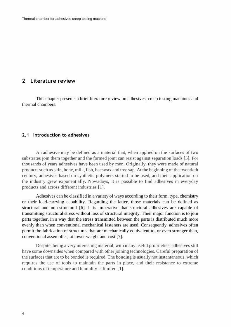
ZWICK offers an electromechanical creep testing machine – Figure 6 – with five or
six individually controlled test axis, each one with a maximum load capacity of 10 kN. This
equipment was designed to perform tests for long periods of time, up to 10,000 h. It is also
possible to have incorporated an irremovable climate chamber that can operate between -70
and 250 [10].
Figure 6 – ZWICK’s multi-station creep testing machine [10].
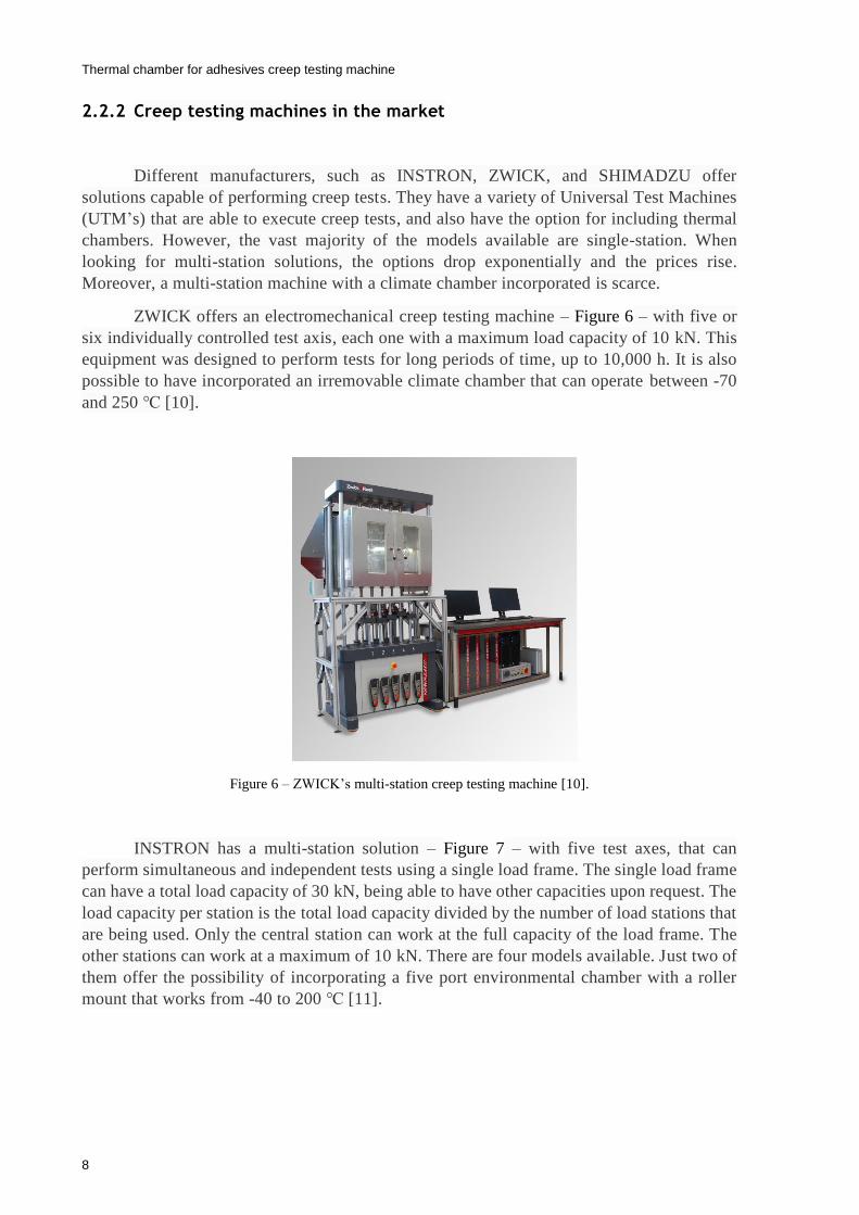
INSTRON has a multi-station solution – Figure 7 – with five test axes, that can
perform simultaneous and independent tests using a single load frame. The single load frame
can have a total load capacity of 30 kN, being able to have other capacities upon request. The
load capacity per station is the total load capacity divided by the number of load stations that
are being used. Only the central station can work at the full capacity of the load frame. The
other stations can work at a maximum of 10 kN. There are four models available. Just two of
them offer the possibility of incorporating a five port environmental chamber with a roller
mount that works from -40 to 200 [11].
Thermal chamber for adhesives creep testing machine
9
Figure 7 – INSTRON’s multi-station creep testing machine [11].
2.3 Thermal chambers
Generically, a thermal chamber is an equipment that allows temperature control in a
confined volume. Depending on the application, thermal chambers can work above, below or
both above and below RT. They can have humidity control and allow the introduction of
different gases in the inner volume to create a specific atmosphere. These equipments are
commonly used in many applications, namely in the food industry, medicine, pharmacology,
and chemistry [12] [13] [14] [15].
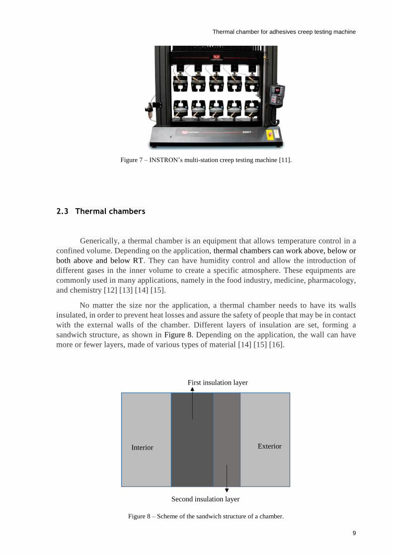
No matter the size nor the application, a thermal chamber needs to have its walls
insulated, in order to prevent heat losses and assure the safety of people that may be in contact
with the external walls of the chamber. Different layers of insulation are set, forming a
sandwich structure, as shown in Figure 8. Depending on the application, the wall can have
more or fewer layers, made of various types of material [14] [15] [16].
Figure 8 – Scheme of the sandwich structure of a chamber.
Interior Exterior
First insulation layer
Second insulation layer

Thermal chamber for adhesives creep testing machine
10
2.3.1 Heating system
The heating process in thermal chambers for creep testing machines is usually done by
forced convection. A fan either blows or vacuums air through or from the heating element,
increasing the air’s temperature, which spreads over the volume of the chamber. With this
method, the temperature inside the chamber reaches its set point quicker and with smaller
temperature gradients, when compared with the heating process by natural convection, in which
the heating element is set at the bottom part of the chamber, creating upwards convection
currents [13] [16].
According to Joule’s first law, when an electrical current flows through a conductive
material it generates a heat power that is directly proportional to the product of the material’s
resistance per the square of the current [17]. This is the principle of functioning of a heating
element, where a piece of conductive material with a certain resistance carries an electrical
current, generating heat.
There are several types of heating elements composed of different alloys and shapes
that fulfill the needs of each application [18]. By reading the product data sheets of two major
heating element manufacturers – KANTHAL and WATTACO – it becomes evident that the
combinations of alloys that exist in the market are vast, so naming all of them would be too
extensive for the purpose of this dissertation. Three examples of heating elements are depicted
in Figure 9.
Figure 9 – Examples of heating elements [18].
According to the KANTHAL Appliance alloys handbook, this manufacturer has
heating elements of:
NiFe;
Austenitic alloys – NiCr, NiCrFe;
Ferritic alloys – FeCrAl;
Copper-nickel alloys [19].
Thermal chamber for adhesives creep testing machine
11
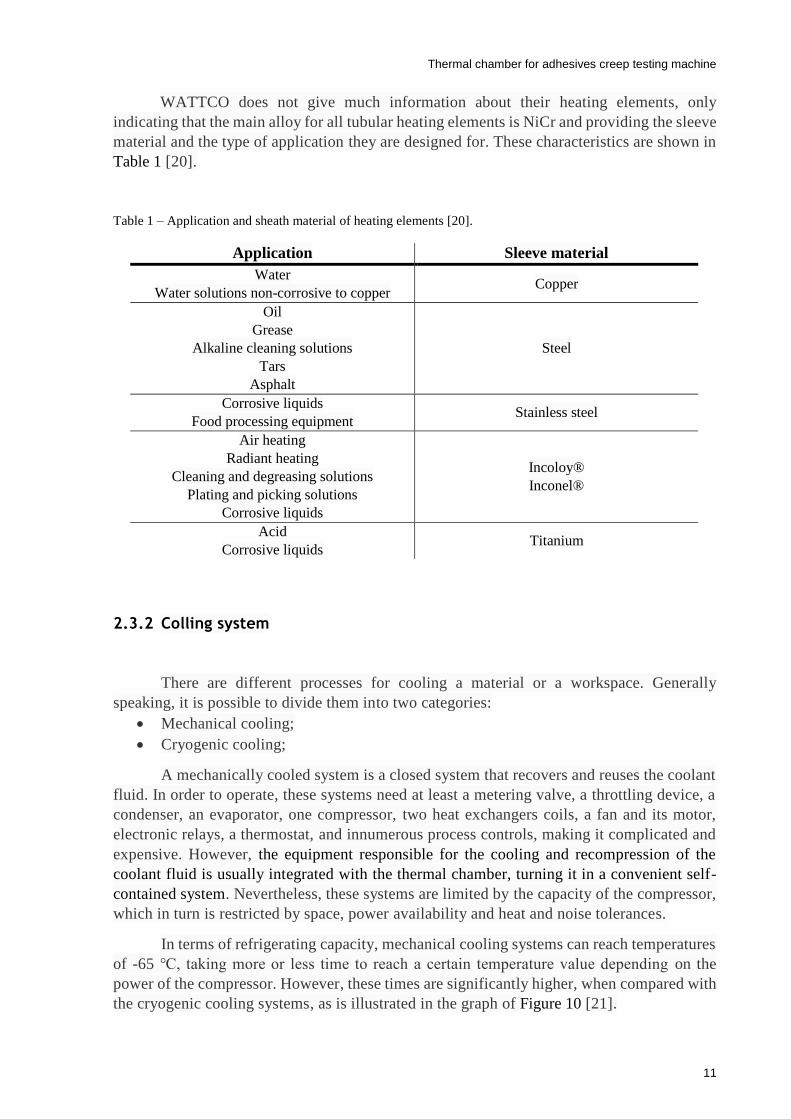
WATTCO does not give much information about their heating elements, only
indicating that the main alloy for all tubular heating elements is NiCr and providing the sleeve
material and the type of application they are designed for. These characteristics are shown in
Table 1 [20].
Table 1 – Application and sheath material of heating elements [20].
2.3.2 Colling system
There are different processes for cooling a material or a workspace. Generally
speaking, it is possible to divide them into two categories:
Mechanical cooling;
Cryogenic cooling;
A mechanically cooled system is a closed system that recovers and reuses the coolant
fluid. In order to operate, these systems need at least a metering valve, a throttling device, a
condenser, an evaporator, one compressor, two heat exchangers coils, a fan and its motor,
electronic relays, a thermostat, and innumerous process controls, making it complicated and
expensive. However, the equipment responsible for the cooling and recompression of the
coolant fluid is usually integrated with the thermal chamber, turning it in a convenient self-
contained system. Nevertheless, these systems are limited by the capacity of the compressor,
which in turn is restricted by space, power availability and heat and noise tolerances.
In terms of refrigerating capacity, mechanical cooling systems can reach temperatures
of -65 , taking more or less time to reach a certain temperature value depending on the
power of the compressor. However, these times are significantly higher, when compared with
the cryogenic cooling systems, as is illustrated in the graph of Figure 10 [21].
Application Sleeve material
Water
Water solutions non-corrosive to copper Copper
Oil
Grease
Alkaline cleaning solutions
Tars
Asphalt
Steel
Corrosive liquids
Food processing equipment Stainless steel
Air heating
Radiant heating
Cleaning and degreasing solutions
Plating and picking solutions
Corrosive liquids
Incoloy®
Inconel®
Acid
Corrosive liquids Titanium

Thermal chamber for adhesives creep testing machine
12
Figure 10 – Temperature versus time for different methods of cooling [21].
Contrary to the previous systems, the cryogenic solution is, in general, open. A
cryogenic coolant is injected in the chamber, cooling it down and is then expelled to the
atmosphere. The most common coolants are CO2 and N2. Being part of the Earth’s
atmosphere, they do not represent any harm to the environment. Although, if the workspace
where the cryogenic coolant fluids are being exhausted is not big enough and/or well
ventilated, the concentration of oxygen in the room can drop to levels that could be harmful
to humans.
The main components of a cryogenic cooling system are a supply vessel with the
cryogenic coolant, pressure reducer, a hose, a filter, a safety valve, a metering valve, and a
throttling device. This is a shorter and less complex list than the one mentioned for mechanical
cooling systems. The hardest part of cryogenic cooling is to compress and liquefy the coolant.
That responsibility is removed from the user of the system, since the vessel containing the
cryogenic coolant can be bought to a supplier that does all of the work. This way of cooling
is easy and cheap to implement and achieves great results in terms of temperature and time.
However, the cost of the coolant is much higher than the cost of electricity required for the
mechanical cooling system.
A cryogenic cooling system that uses L-CO2 (liquid CO2) can reach a temperature of
-80 in much less time than a mechanical system – Figure 10. If L-N2 (liquid N2) is used
instead, the temperature can drop to -175 or even more [21] [22].
2.3.3 Market solutions for thermal chambers
As said in section 2.2, the availability of multi-station creep testing machines is very
reduced due to the lack of market demand. Therefore, the information regarding thermal
chambers for these machines is also scarce. To bypass this absence of information, it is
Thermal chamber for adhesives creep testing machine
13
necessary to resort to the data of thermal chambers designed for single-station creep testing
machines and then interpret and adapt the information to bigger volumes chambers.
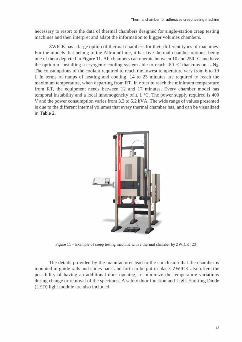
ZWICK has a large option of thermal chambers for their different types of machines.
For the models that belong to the AllroundLine, it has five thermal chamber options, being
one of them depicted in Figure 11. All chambers can operate between 10 and 250 and have
the option of installing a cryogenic cooling system able to reach -80 that runs on L-N2.
The consumptions of the coolant required to reach the lowest temperature vary from 6 to 19
l. In terms of ramps of heating and cooling, 14 to 23 minutes are required to reach the
maximum temperature, when departing from RT. In order to reach the minimum temperature
from RT, the equipment needs between 12 and 17 minutes. Every chamber model has
temporal instability and a local inhomogeneity of ± 1 . The power supply required is 400
V and the power consumption varies from 3.3 to 5.2 kVA. The wide range of values presented
is due to the different internal volumes that every thermal chamber has, and can be visualized
in Table 2.
Figure 11 – Example of creep testing machine with a thermal chamber by ZWICK [23].
The details provided by the manufacturer lead to the conclusion that the chamber is
mounted in guide rails and slides back and forth to be put in place. ZWICK also offers the
possibility of having an additional door opening, to minimize the temperature variations
during change or removal of the specimen. A safety door function and Light Emitting Diode
(LED) light module are also included.
Thermal chamber for adhesives creep testing machine
14
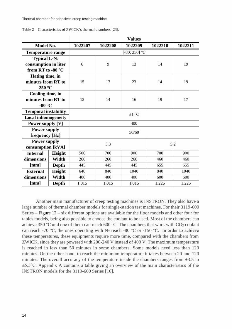
Table 2 – Characteristics of ZWICK’s thermal chambers [23].
Another main manufacturer of creep testing machines is INSTRON. They also have a
large number of thermal chamber models for single-station test machines. For their 3119-600
Series – Figure 12 – six different options are available for the floor models and other four for
tables models, being also possible to choose the coolant to be used. Most of the chambers can
achieve 350 and one of them can reach 600 . The chambers that work with CO2 coolant
can reach -70 , the ones operating with N2 reach -80 or -150 . In order to achieve
these temperatures, these equipments require more time, compared with the chambers from
ZWICK, since they are powered with 200-240 V instead of 400 V. The maximum temperature
is reached in less than 50 minutes in some chambers. Some models need less than 120
minutes. On the other hand, to reach the minimum temperature it takes between 20 and 120
minutes. The overall accuracy of the temperature inside the chambers ranges from ±3.5 to
±5.5. Appendix A contains a table giving an overview of the main characteristics of the
INSTRON models for the 3119-600 Series [16].
Values
Model No. 1022207 1022208 1022209 1022210 1022211
Temperature range [-80; 250]
Typical L-N2
consumption in liter
from RT to -80
6 9 13 14 19
Hating time, in
minutes from RT to
250
15 17 23 14 19
Cooling time, in
minutes from RT to
-80
12 14 16 19 17
Temporal instability ±1
Local inhomogeneity
Power supply [V] 400
Power supply
frequency [Hz] 50/60
Power supply
consumption [kVA] 3.3 5.2
Internal
dimensions
[mm]
Height 500 700 900 700 900
Width 260 260 260 460 460
Depth 445 445 445 655 655
External
dimensions
[mm]
Height 640 840 1040 840 1040
Width 400 400 400 600 600
Depth 1,015 1,015 1,015 1,225 1,225

Thermal chamber for adhesives creep testing machine
15
Figure 12 – Example of two creep testing machines with thermal chambers from INSTRON [16].
The chambers use forced convection to spread the heated air or the coolant,
accelerating the heat transfer and ensuring a more homogenous temperature inside the
chamber. Air at RT flows through a case that is between the insulation and the outer panels,
allowing more efficient insulation, as it is depicted in Figure 13. These equipments have other
features, such removable wedge ports ensuring a quick and easy setup of the chambers
without interfering with the pull rods and roller mounting can be installed to remove the
chamber from the test space.
Figure 13 – Scheme of the airflow through the chamber [16].

Thermal chamber for adhesives creep testing machine
16
2.4 Discussion
The implementation of a thermal chamber in the already existing creep testing machine
will add significant value to the AJPU group, allowing them to have a fully equipped creep
testing machine
The main idea of how a thermal chamber should behave, and how the heating and the
cooling systems work was described in this chapter. Cryogenic cooling was also shown to be a
good option. Moreover, the need for an extra layer of insulation, where air flows through it,
ensuring better insulation and limiting the exterior case temperature to levels not harmful to
humans, was perceived.
Thermal chamber for adhesives creep testing machine
17
3 Thermal chamber design
This chapter describes the design and validation of the thermal chamber and the heat
insulator that prevents the overheating of the load cells implemented in the top of the creep
testing machine.
3.1 Heat transfer concepts and principles
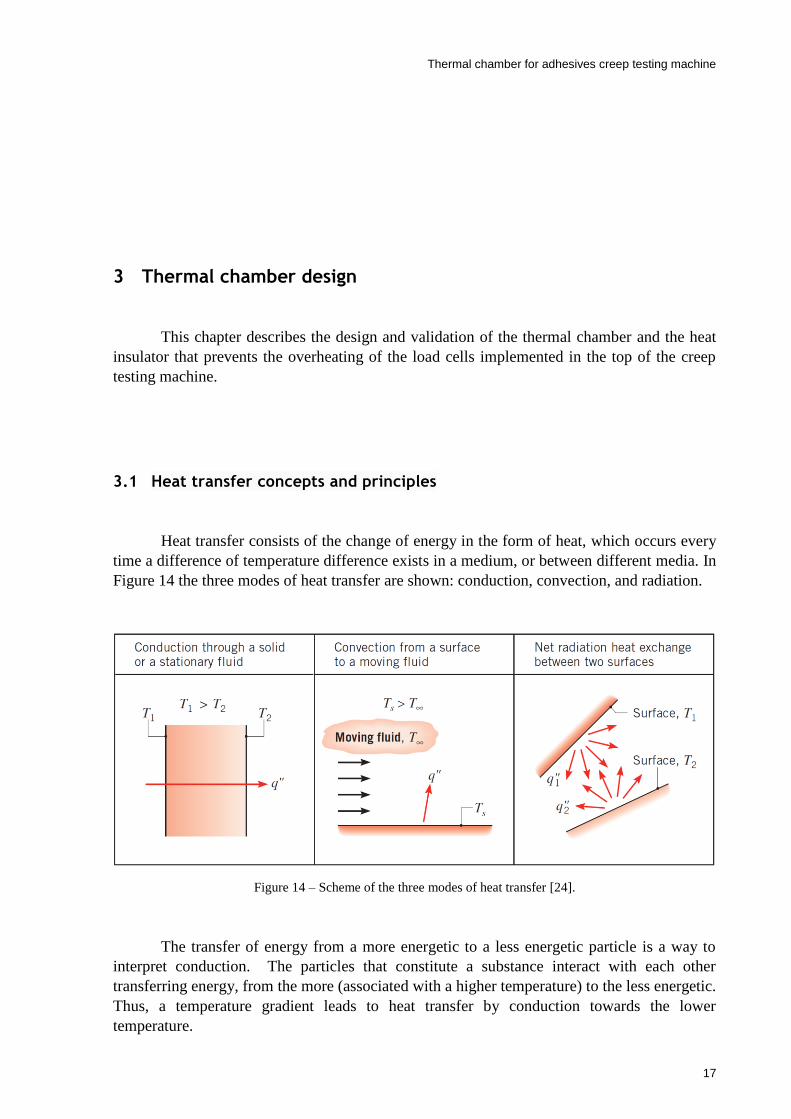
Heat transfer consists of the change of energy in the form of heat, which occurs every
time a difference of temperature difference exists in a medium, or between different media. In
Figure 14 the three modes of heat transfer are shown: conduction, convection, and radiation.
Figure 14 – Scheme of the three modes of heat transfer [24].
The transfer of energy from a more energetic to a less energetic particle is a way to
interpret conduction. The particles that constitute a substance interact with each other
transferring energy, from the more (associated with a higher temperature) to the less energetic.
Thus, a temperature gradient leads to heat transfer by conduction towards the lower
temperature.

Thermal chamber for adhesives creep testing machine
18
The Fourier’ law is used to quantify the heat flux that flows through a material. This
law translates into the following equation, under the steady-state conditions shown in Figure
15,
Figure 15 – One-dimensional heat transfer by conduction [24].
where 𝑞𝑥′′ is the conduction heat flux, expressed in W/m2 and 𝑘 is the thermal conductivity, a
propriety that varies with the material and is expressed in W/m⸱K. The length of the material,
where the heat flows is represented by 𝐿 and is expressed in meters and the difference of
temperature between 𝑇1 and 𝑇2 is represented by ∆𝑇.
The heat transfer by convection is divided into two mechanisms: diffusion – heat
transfer by random molecular motion – and the energy transferred by macroscopic motion of
the fluid. It can be classified in forced or free (or natural) convection, according to the nature
of the flow. In forced convection, an external source forces the movement of the fluid that
transfers heat with a surface – Figure 16. In natural convection the flow is induced by a
buoyancy force, which occurs due to the variation of temperature in the fluid, generating density
differences.
Figure 16 – Scheme of heat transfer by convection [24].
𝑞𝑥′′ = 𝑘
∆𝑇
𝐿 (3.1)
Thermal chamber for adhesives creep testing machine
19
Regardless of the convection being forced or natural, the equation that quantifies the
amount of heat flux is the same and called Newton’s law of cooling
where 𝑞′′ represents the convection heat flux, expressed in W/m2 and ℎ is the convection
coefficient, expressed in W/m2⸱K. This coefficient is determined by the fluid motion and
thermodynamic proprieties, boundary layer, and surface geometry. The heat flux is proportional
to the difference of temperatures, being 𝑇∞ the temperature of the fluid and 𝑇𝑠 the temperature
of the surface.
The Nusselt number is a dimensionless parameter, which correlates the convection
coefficient, the thermal conductivity of the fluid and a spatial coordinate. It can be defined as
the ratio of convection to pure conduction heat transfer and is expressed by the equation
The Nusselt number can also be calculated based on empirically and assumes drastically
different values according to the geometry of the surface and the nature (internal or external)
of the flow. Combining the equation above and one of the equations obtained by empirical
experience, it is possible to reach a value of the convection coefficient.
Thermal radiation is the energy emitted by any substance at a temperature greater than
absolute zero (0 K). This energy is transported by electromagnetic waves, not requiring the
presence of a material medium for heat transfer to take place. The Stefan-Boltzmann law
quantifies the energy that is emitted from a surface per unit area by radiation and is represented
in the following equation
where 𝐸 represents the heat flux by radiation and is denominated surface emissive power,
expressed in W/m2. The parameter 𝜀 is called emissivity and measures how efficiently a body
emits energy when compared to a blackbody. Its values are in the interval 0 ≤ 𝜀 ≤ 1. The
Stefan-Boltzmann constant is represented by 𝜎, with a value of 5.67×10⁻⁸ W/m2⸱K4. Finally,
the temperature of the body is defined by 𝑇𝑠 [24].
3.2 Thermal and dimensional restrictions for the chamber
The thermal chamber will be incorporated in the creep testing machine developed by
Freire [2], Pina [3] and Silva [4]. In order to fit between the existing two support columns, the
chamber cannot exceed 625 mm in width. Evidently, this value should be a little bit lower to
𝑞′′ = ℎ(𝑇∞ − 𝑇𝑠) (3.2)
𝑁𝑢 =ℎ𝐿
𝑘𝑓 (3.3)
𝐸 = 𝜀𝜎𝑇𝑠4 (3.4)
Thermal chamber for adhesives creep testing machine
20
ensure that the equipment does not hit the columns when installing it. In terms of height, the
chamber has to accommodate the entire stroke by the grips of the rods of the machine.
Regarding the chamber’s depth, it should comply with the size of the rods and fit the workspace.
The chamber has to operate in a range of temperatures between -100 and 200 .
The homogeneity of the temperature has to be as high as possible, avoiding thermal gradients
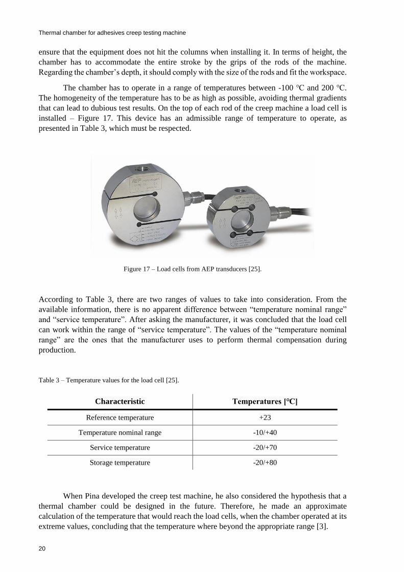
that can lead to dubious test results. On the top of each rod of the creep machine a load cell is
installed – Figure 17. This device has an admissible range of temperature to operate, as
presented in Table 3, which must be respected.
Figure 17 – Load cells from AEP transducers [25].
According to Table 3, there are two ranges of values to take into consideration. From the
available information, there is no apparent difference between “temperature nominal range”
and “service temperature”. After asking the manufacturer, it was concluded that the load cell
can work within the range of “service temperature”. The values of the “temperature nominal
range” are the ones that the manufacturer uses to perform thermal compensation during
production.
Table 3 – Temperature values for the load cell [25].
When Pina developed the creep test machine, he also considered the hypothesis that a
thermal chamber could be designed in the future. Therefore, he made an approximate
calculation of the temperature that would reach the load cells, when the chamber operated at its
extreme values, concluding that the temperature where beyond the appropriate range [3].
Characteristic Temperatures []
Reference temperature +23
Temperature nominal range -10/+40
Service temperature -20/+70
Storage temperature -20/+80

Thermal chamber for adhesives creep testing machine
21
3.3 Heat insulator
As said in section 3.2, the value of temperature that reaches the load cells is not low
enough to ensure the proper functioning of these transducers. Therefore, it is necessary to create
a device for protecting these equipments. A heat sink was the first idea considered, because it
would allow the dissipation of heat that flows through the upper rod of the creep testing
machine, reducing the temperature that reaches the load cells. In addition, Pina suggested the
same approach during the development of the creep testing machine [3].
The main goal of a heat sink is to dissipate heat, so it is necessary to increase the heat
flux going out of the upper rod. According to what has been presented in section 3.1, the best
way to increase the heat flux is to expand the surface area. So, a heat sink constituted by a
stainless steel slotted tube with aluminum fins attached was designed. A representation of the
heat sink is depicted in Figure 18 and the most relevant characteristics of the materials are
summarized in Table 4. The choice of material is due to the fact that aluminum has a much
higher thermal conductivity than stainless steel. Therefore, in order to prevent the increase of
heat flux by conduction, which results in a higher temperature near the load cell, the tube around
the upper rod needs to have a low thermal conductivity coefficient.
Figure 18 – Example of a heat sink [3].
The heat transfer that occurs in the heat sink is due to conduction, natural convection,
and radiation. Those phenomena occur simultaneously and in three spatial dimensions, making
them very hard to study without resort to simulation software. In order to obtain fast results that
allow implementing eventual changes to the heat sink, heat transfer by radiation was temporally
suppressed from the thermal analysis.
Slotted
tube
Fins

Thermal chamber for adhesives creep testing machine
22
Table 4 – Characteristics values of stainless steel AISI 304 and aluminum 1060 alloy.
The software utilized for the simulations was SolidWorks, since it was the one used to
design the components of the heat sink. To set up the thermal simulation it is required to create
a mesh, input the thermal loads and specify the materials and their proprieties. The mesh divides
the components under study in small geometric elements and analyzes each of them. It is
possible to refine the mesh adjusting the number of small geometric elements and making them
smaller. In the thermal load section, it is possible to set the values of temperature, convection,
heat flux, heat power and radiation for the desired surfaces. To choose the materials, the
software has a very complete database from which it is possible to select different materials or
even create new ones.
With all restrictions defined, the simulation parameters have to be specified. At this
point, the heating elements and the type of cooling system were still not determined. Therefore,
a temperature was defined in one section of the rod where the heat sink was supposed to be
connected. This temperature corresponds to the extreme values that the thermal chamber can
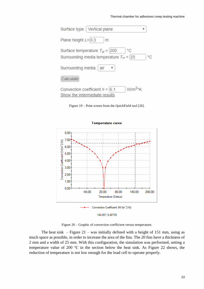
operate at, that is -100 and 200 . Evaluating the convection coefficient is not an easy task.
The literature on the subject is vast and there are innumerous equations that try to establish the
best approximation to the reality. The Nusselt equation for a cylinder can be used for a vertical
plane [24]. So, utilizing an online tool from QuickField that calculates the natural convection
coefficient [26] – Figure 19 – those values were obtained for the range of temperatures needed,
obtaining a graph of the evolution of the coefficient for different temperatures, as shown in
Figure 20. Now it is possible to define all the thermal loads required to run the thermal
simulation.
Values
Characteristic Stainless steel AISI
304 Aluminum 1060 alloy
Mass density [kg/m3] 8000 2,700
Thermal expansion coefficient [K-1] 1.8×10⁻⁵ 2.4×10⁻⁵
Thermal conductivity [J/m⸱K] 16 200
Specific heat [J/kg⸱K] 500 900
Thermal chamber for adhesives creep testing machine
23
Figure 19 – Print screen from the QuickField tool [26].
Figure 20 – Graphic of convection coefficient versus temperature.
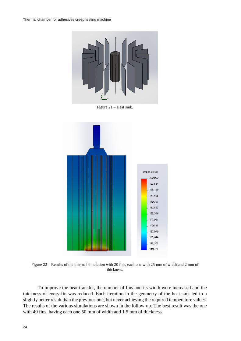
The heat sink – Figure 21 – was initially defined with a height of 151 mm, using as
much space as possible, in order to increase the area of the fins. The 20 fins have a thickness of
2 mm and a width of 25 mm. With this configuration, the simulation was performed, setting a
temperature value of 200 in the section below the heat sink. As Figure 22 shows, the
reduction of temperature is not low enough for the load cell to operate properly.
Thermal chamber for adhesives creep testing machine
24
Figure 21 – Heat sink.
Figure 22 – Results of the thermal simulation with 20 fins, each one with 25 mm of width and 2 mm of
thickness.
To improve the heat transfer, the number of fins and its width were increased and the
thickness of every fin was reduced. Each iteration in the geometry of the heat sink led to a
slightly better result than the previous one, but never achieving the required temperature values.
The results of the various simulations are shown in the follow-up. The best result was the one
with 40 fins, having each one 50 mm of width and 1.5 mm of thickness.
Slotted
tube
Fin

Thermal chamber for adhesives creep testing machine
25
Figure 23 – Results of the thermal simulation with 40 fins, each one with 25 mm of width and 2 mm of
thickness.
Figure 24 – Results of the thermal simulation with 40 fins, each one with 50 mm of width and 2 mm of
thickness.
Thermal chamber for adhesives creep testing machine
26
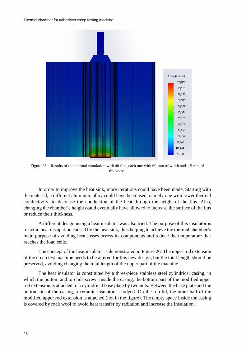
Figure 25 – Results of the thermal simulation with 40 fins, each one with 60 mm of width and 1.5 mm of
thickness.
In order to improve the heat sink, more iterations could have been made. Starting with
the material, a different aluminum alloy could have been used, namely one with lower thermal
conductivity, to decrease the conduction of the heat through the height of the fins. Also,
changing the chamber’s height could eventually have allowed to increase the surface of the fins
or reduce their thickness.
A different design using a heat insulator was also tried. The purpose of this insulator is
to avoid heat dissipation caused by the heat sink, thus helping to achieve the thermal chamber’s
main purpose of avoiding heat losses across its components and reduce the temperature that
reaches the load cells.
The concept of the heat insulator is demonstrated in Figure 26. The upper rod extension
of the creep test machine needs to be altered for this new design, but the total length should be
preserved, avoiding changing the total length of the upper part of the machine.
The heat insulator is constituted by a three-piece stainless steel cylindrical casing, in
which the bottom and top lids screw. Inside the casing, the bottom part of the modified upper
rod extension is attached to a cylindrical base plate by two nuts. Between the base plate and the
bottom lid of the casing, a ceramic insulator is lodged. On the top lid, the other half of the
modified upper rod extension is attached (not in the figure). The empty space inside the casing
is covered by rock wool to avoid heat transfer by radiation and increase the insulation.
Thermal chamber for adhesives creep testing machine
27
Figure 26 – First concept of the heat insulator.
This configuration allows the required force transmission for the creep test. A traction
force is exerted on the upper rod, compresses the ceramic insulator and finally is transmitted to
the bottom of the casing.
The ceramic insulator has to have a very low conduction coefficient, to minimize the
heat flow that reaches the top of the casing and to have a compression stress that holds the
forces of the creep testing machine. After investigating the best ceramic that fulfils the
requirements, the company MJAmaral advised using cordierite, which characteristics are
described in Table 5.
Table 5 – Cordierite proprieties.
Characteristic Value
Density 1,600 [ kg/m3]
Elastic modulus 120 [GPa]
Compressive strength 600 [MPa]
Thermal conductivity 1.3 [ J/m⸱K]
Specific heat 800 [ J/kg⸱K]
Maximum service temperature 1,300[ ]
Upper rod extension
modified
Cylindrical base plate
Cylindrical casing
Top lid
Bottom lid
Ceramic insulator
Nuts

Thermal chamber for adhesives creep testing machine
28
The rock wool used in the heat insulator suppresses the heat transfer by radiation
between the internal components and the external casing. It also offers good thermic insulation,
because it has a very low thermal conductivity, as shown in Table 6.
Table 6 – Rock wool proprieties.
To avoid losing more time developing the design of the heat insulator and without
guarantees that it would be a viable solution, a quick thermal simulation was executed. The
definition of thermal loads followed a similar principle of the ones performed before.
Convection was defined based on the values shown in Figure 20. A temperature value of 200
for the bottom part of the upper rod extension was also defined. The heat transfer by radiation
that occurs between the exterior case and the atmosphere was characterized by an emissivity of
0.4 and a view factor of 1, while the radiation inside the heat insulator was neglected.
Figure 27 – Results of the thermal simulation made for the heat insulator’s initial design.
Characteristic Value
Density 25 [ kg/m3]
Thermal conductivity 0.04 [ J/m⸱K]
Thermal chamber for adhesives creep testing machine
29
As shown in Figure 27, there was a significant reduction in the temperature towards an
acceptable range. Despite not being finished, the tested model for the heat insulator showed
promising results.
Before making the necessary modifications to the heat insulator, it is important to
calculate the minimum thickness of the cylindrical ceramic insulator required to hold the forces
at stake. The upper rod extension has a diameter of 35 mm and the base plate needs to have a
gap for centering the ceramic insulator, as shown in Figure 26. Thus, an interior diameter of 50
mm was established for the ceramic. The main purpose here is to ensure that the compressive
strength of the material is higher than the compressive stress that it will be subjected to, as
expressed in the following equation
where the area (𝐴) is equal to 𝜋
4∙ [𝑑𝑒𝑥𝑡𝑒𝑟𝑛𝑎𝑙
2 − 𝑑𝑖𝑛𝑡𝑒𝑟𝑛𝑎𝑙2 ], the maximum force (𝐹) is 3000 N and
the compressive strength of the ceramic insulator is 600 MPa, as described in Table 5; all the
variables are known except for the external diameter, which was calculated to be 50.064 mm.
Therefore, there are no significant restrictions for the minimum thickness of the ceramic
insulator.
After the calculations of the minimum thickness of the ceramic insulator, some
modifications were implemented in the heat insulator, which are shown in Figure 28. The top
and bottom lids increased in thickness to avoid major displacements when the components are
under load. The diameter of the casing also increased, allowing more space for the ceramic
insulator and the rock wool. The top part of the upper rod extension was also modified. The top
and bottom parts of the modified component are attached by nuts to the top lid and the base
plate, respectively (not in the figure).
𝜎𝑐𝑜𝑚𝑝 >𝐹
𝐴 (3.5)
Thermal chamber for adhesives creep testing machine
30
Figure 28 – Modified heat insulator.
With this new configuration, another thermal simulation was run. The applied thermal
loads were the same as in the previous simulation and the results are shown in Figure 29.
Another simulation with similar thermal loads was also run, but a value of -100 ºC was used
instead of 200 ºC – Figure 30.
The results show that the temperature values that reach the load cell are in the range of
its admissible service temperature. Despite being acceptable results, it would have been better
to reach the temperature’s nominal range, which is the temperature at which the manufacture
performs the thermal compensation during production. Another inconvenience of this design
was the oversized diameter of the casing which made the heat insulator of each station very
close. This allows significant heat change, not predicted in the thermal simulations which were
run. Because the external casing needs to be reduced, both the ceramic insulator and the rock
wool should be reduced as well.
Thermal chamber for adhesives creep testing machine
31
Figure 29 – Results of thermal simulation with a temperature load of 200.
Figure 30 – Results of thermal simulation with a temperature load of -100.
Thermal chamber for adhesives creep testing machine
32
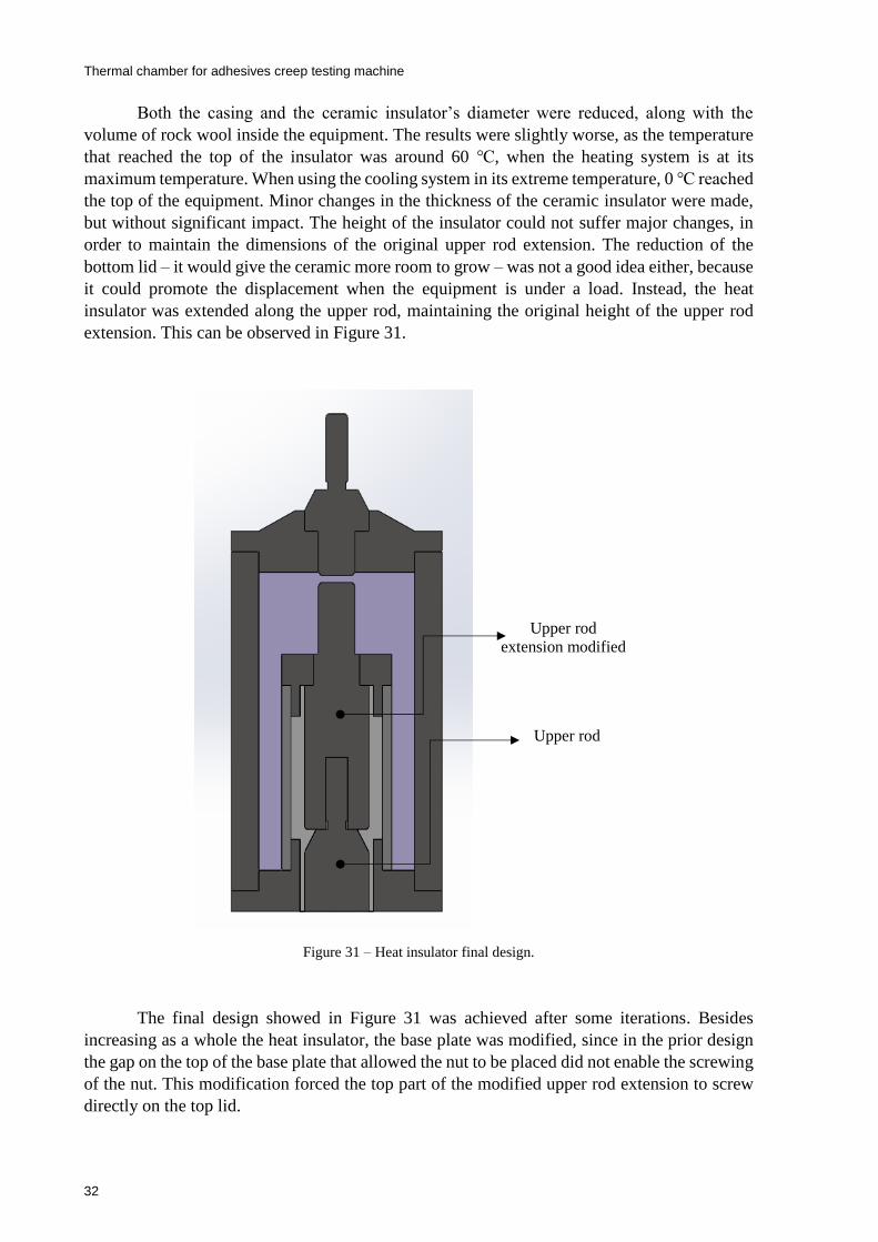
Both the casing and the ceramic insulator’s diameter were reduced, along with the
volume of rock wool inside the equipment. The results were slightly worse, as the temperature
that reached the top of the insulator was around 60 , when the heating system is at its
maximum temperature. When using the cooling system in its extreme temperature, 0 reached
the top of the equipment. Minor changes in the thickness of the ceramic insulator were made,
but without significant impact. The height of the insulator could not suffer major changes, in
order to maintain the dimensions of the original upper rod extension. The reduction of the
bottom lid – it would give the ceramic more room to grow – was not a good idea either, because
it could promote the displacement when the equipment is under a load. Instead, the heat
insulator was extended along the upper rod, maintaining the original height of the upper rod
extension. This can be observed in Figure 31.
Figure 31 – Heat insulator final design.
The final design showed in Figure 31 was achieved after some iterations. Besides
increasing as a whole the heat insulator, the base plate was modified, since in the prior design
the gap on the top of the base plate that allowed the nut to be placed did not enable the screwing
of the nut. This modification forced the top part of the modified upper rod extension to screw
directly on the top lid.
Upper rod
extension modified
Upper rod
Thermal chamber for adhesives creep testing machine
33
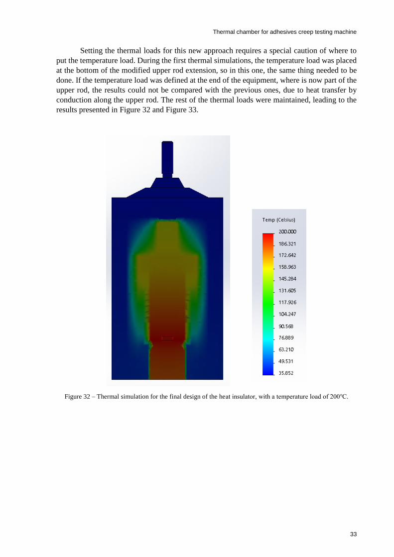
Setting the thermal loads for this new approach requires a special caution of where to
put the temperature load. During the first thermal simulations, the temperature load was placed
at the bottom of the modified upper rod extension, so in this one, the same thing needed to be
done. If the temperature load was defined at the end of the equipment, where is now part of the
upper rod, the results could not be compared with the previous ones, due to heat transfer by
conduction along the upper rod. The rest of the thermal loads were maintained, leading to the
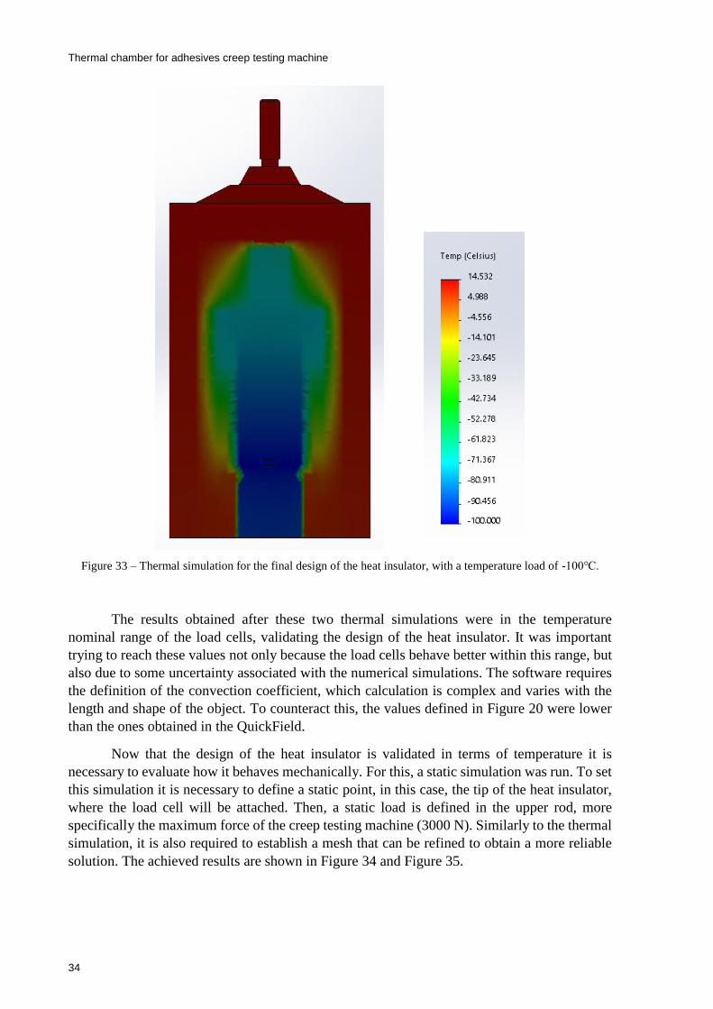
results presented in Figure 32 and Figure 33.
Figure 32 – Thermal simulation for the final design of the heat insulator, with a temperature load of 200.
Thermal chamber for adhesives creep testing machine
34
Figure 33 – Thermal simulation for the final design of the heat insulator, with a temperature load of -100.
The results obtained after these two thermal simulations were in the temperature
nominal range of the load cells, validating the design of the heat insulator. It was important
trying to reach these values not only because the load cells behave better within this range, but
also due to some uncertainty associated with the numerical simulations. The software requires
the definition of the convection coefficient, which calculation is complex and varies with the
length and shape of the object. To counteract this, the values defined in Figure 20 were lower
than the ones obtained in the QuickField.
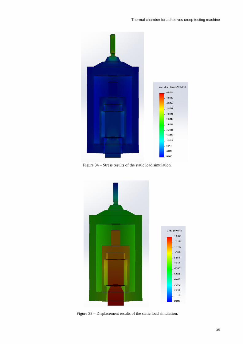
Now that the design of the heat insulator is validated in terms of temperature it is
necessary to evaluate how it behaves mechanically. For this, a static simulation was run. To set
this simulation it is necessary to define a static point, in this case, the tip of the heat insulator,
where the load cell will be attached. Then, a static load is defined in the upper rod, more
specifically the maximum force of the creep testing machine (3000 N). Similarly to the thermal
simulation, it is also required to establish a mesh that can be refined to obtain a more reliable
solution. The achieved results are shown in Figure 34 and Figure 35.
Thermal chamber for adhesives creep testing machine
35
Figure 34 – Stress results of the static load simulation.
Figure 35 – Displacement results of the static load simulation.

Thermal chamber for adhesives creep testing machine
36
It is possible to verify that the stress along the heat insulator is very low. The maximum
values of stress occur on the top of the component and are not significant. In terms of
displacement, the values are perfectly acceptable. In the exterior casing, the displacement is
between 5 and 8 microns, the maximum displacement is around 13 microns in the upper rod,
which does not influence significantly the measures of creep.
Now, having performed the thermal and mechanical validations of the heat insulator, its
design is concluded.
3.4 Structural design of the chamber
As said in chapter 2, the thermal chambers have at least one insulation layer. The layer
function is to preserve the heat inside the chamber and to protect the operator of the equipment.
Although this is a thermal concern, the number of insulation layers will affect the structural
design of the chamber. Having more layers will improve the thermal behavior of the chamber,
but the total size of these layers is conditioned by the available space and each additional layer
implies an increase of the total cost of the thermal chamber.
The most interesting solution for the insulation layers is to have a shell involving the
internal volume, constituted by a low conductivity material and a second layer where air flows
at RT. Thus, the heat is contained within the internal volume and at the same time, the outer
skin of the chamber is being cooled.
The first idea to design the chamber was to conceive a structure easy to assembly. This
way, the construction and maintenance of the equipment are simplified. Two main design
concepts were sketched. One similar to the thermal chambers of Figure 12, with a small door
and the rest of the equipment as one piece. In this type of configuration, a removable wedge
port allows the chamber to be removed from the test area. Although this solution is interesting
when used in single-station machines, applying it to a three-station machine implies having
three removable wedge ports, which compromises the structure of the chamber. Alternatively,
it is possible to have just one big removable wedge port, which is executable but brings many
concerns in terms of rigidity of the chamber. In the other design, the chamber is split vertically,
resulting in two halves. From here, two different possibilities are available on how to attach the
back half of the chamber to the creep testing machine. It can be mounted in rail mounts, which
allows it to roll back, exiting the test area. Alternatively, it can be attached to one of the columns
of the load frame as the front half will be. This way both halves swing around the axis of a
different column, opening space in the test area.
After some discussion, was adopted the design in which the two chambers are vertically
split and attached to the columns of the load frame.
According to Pina’s [3] initial drawings, there is some space limitation that should have
to be taken into consideration during the design of the chamber. The distance between the
outside stations and the inner wall has to be at least 75 mm. The internal height should have a
value between 700 and 750 mm, to accommodate a 300 mm stroke, that should be taken into
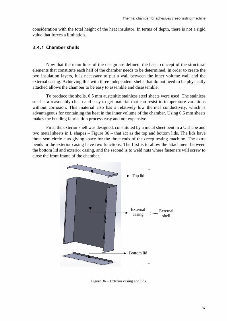
Thermal chamber for adhesives creep testing machine
37
consideration with the total height of the heat insulator. In terms of depth, there is not a rigid
value that forces a limitation.
3.4.1 Chamber shells
Now that the main lines of the design are defined, the basic concept of the structural
elements that constitute each half of the chamber needs to be determined. In order to create the
two insulation layers, it is necessary to put a wall between the inner volume wall and the
external casing. Achieving this with three independent shells that do not need to be physically
attached allows the chamber to be easy to assemble and disassemble.
To produce the shells, 0.5 mm austenitic stainless steel sheets were used. The stainless
steel is a reasonably cheap and easy to get material that can resist to temperature variations
without corrosion. This material also has a relatively low thermal conductivity, which is
advantageous for containing the heat in the inner volume of the chamber. Using 0.5 mm sheets
makes the bending fabrication process easy and not expensive.
First, the exterior shell was designed, constituted by a metal sheet bent in a U shape and
two metal sheets in L shapes – Figure 36 – that act as the top and bottom lids. The lids have
three semicircle cuts giving space for the three rods of the creep testing machine. The extra
bends in the exterior casing have two functions. The first is to allow the attachment between
the bottom lid and exterior casing, and the second is to weld nuts where fasteners will screw to
close the front frame of the chamber.
Figure 36 – Exterior casing and lids.
Top lid
External
casing
Bottom lid
External
shell
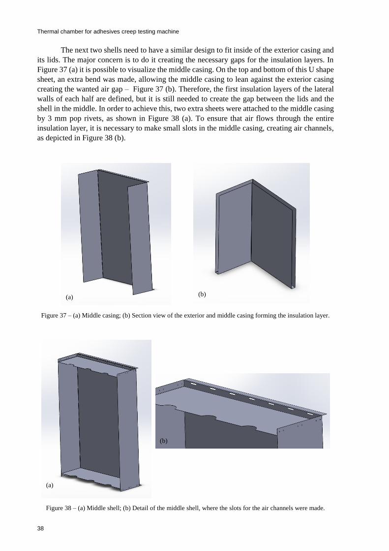
Thermal chamber for adhesives creep testing machine
38
The next two shells need to have a similar design to fit inside of the exterior casing and
its lids. The major concern is to do it creating the necessary gaps for the insulation layers. In
Figure 37 (a) it is possible to visualize the middle casing. On the top and bottom of this U shape
sheet, an extra bend was made, allowing the middle casing to lean against the exterior casing
creating the wanted air gap – Figure 37 (b). Therefore, the first insulation layers of the lateral
walls of each half are defined, but it is still needed to create the gap between the lids and the
shell in the middle. In order to achieve this, two extra sheets were attached to the middle casing
by 3 mm pop rivets, as shown in Figure 38 (a). To ensure that air flows through the entire
insulation layer, it is necessary to make small slots in the middle casing, creating air channels,
as depicted in Figure 38 (b).
Figure 37 – (a) Middle casing; (b) Section view of the exterior and middle casing forming the insulation layer.
Figure 38 – (a) Middle shell; (b) Detail of the middle shell, where the slots for the air channels were made.
(a) (b)
(a)
(b)
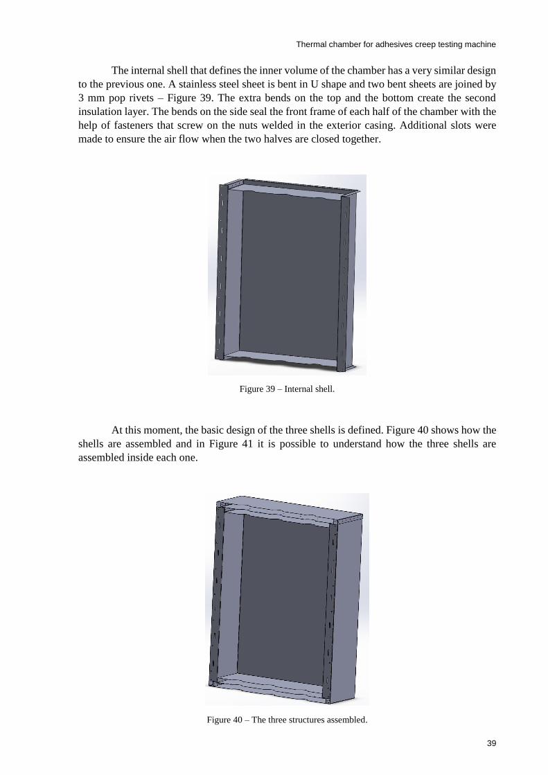
Thermal chamber for adhesives creep testing machine
39
The internal shell that defines the inner volume of the chamber has a very similar design
to the previous one. A stainless steel sheet is bent in U shape and two bent sheets are joined by
3 mm pop rivets – Figure 39. The extra bends on the top and the bottom create the second
insulation layer. The bends on the side seal the front frame of each half of the chamber with the
help of fasteners that screw on the nuts welded in the exterior casing. Additional slots were
made to ensure the air flow when the two halves are closed together.
Figure 39 – Internal shell.
At this moment, the basic design of the three shells is defined. Figure 40 shows how the
shells are assembled and in Figure 41 it is possible to understand how the three shells are
assembled inside each one.
Figure 40 – The three structures assembled.
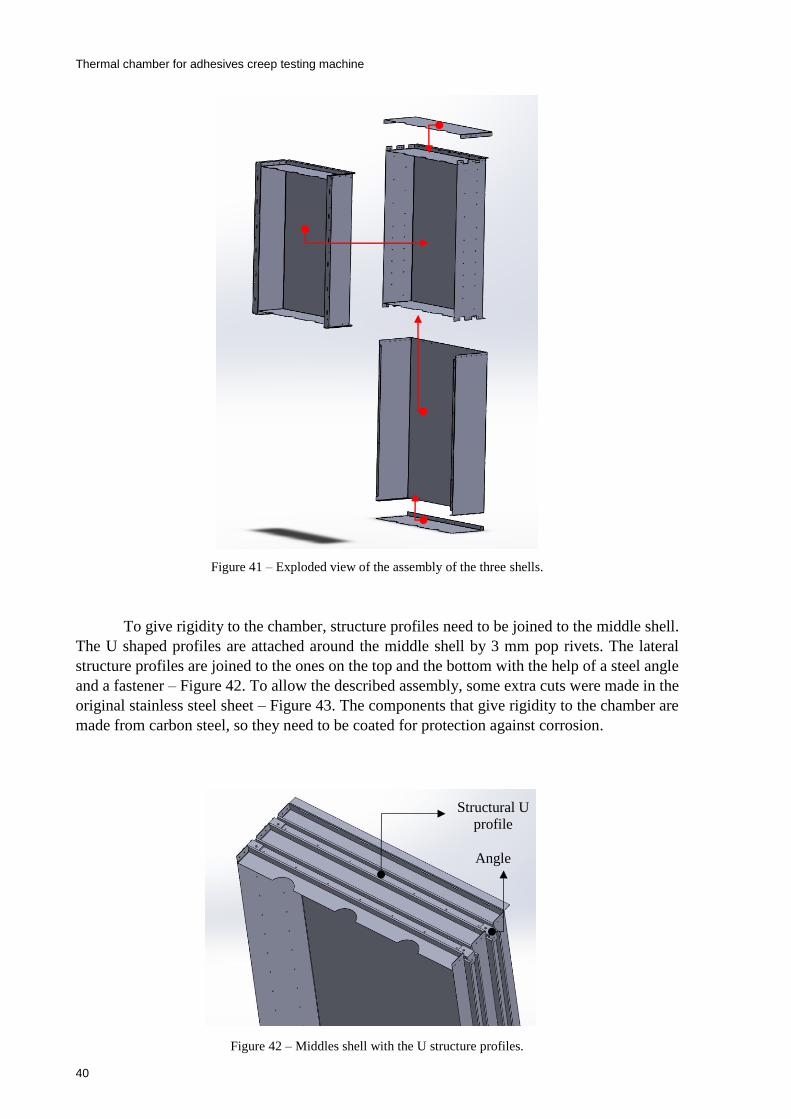
Thermal chamber for adhesives creep testing machine
40
Figure 41 – Exploded view of the assembly of the three shells.
To give rigidity to the chamber, structure profiles need to be joined to the middle shell.
The U shaped profiles are attached around the middle shell by 3 mm pop rivets. The lateral
structure profiles are joined to the ones on the top and the bottom with the help of a steel angle
and a fastener – Figure 42. To allow the described assembly, some extra cuts were made in the
original stainless steel sheet – Figure 43. The components that give rigidity to the chamber are
made from carbon steel, so they need to be coated for protection against corrosion.
Figure 42 – Middles shell with the U structure profiles.
Structural U
profile
Angle

Thermal chamber for adhesives creep testing machine
41
Figure 43 – Extra cuts made in the middle casing.
Some parts of the shells ensure guidance when assembled. Nevertheless, cylindrical
Teflon spacers were glued to the different structures with RTV silicon, guaranteeing a perfect
alignment/centering between the three shells and forming the two insulation chambers. In
Figure 44 it is depicted a detail of the middle shell where a few spacers were glued. In this
example, the spacers lead against the exterior casing, ensuring the alignment/centering. The
RTV silicone was used due to its high resistance to extreme temperatures. Table 7 shows some
proprieties of the RTV silicon.
Figure 44 – Detail of the middle casing with the spacers glued.
Table 7 – Proprieties of the RTV silicon.
Characteristic Value
Temperature range -110 to 180 []
Tensile strength range 2 to 10 [MPa]
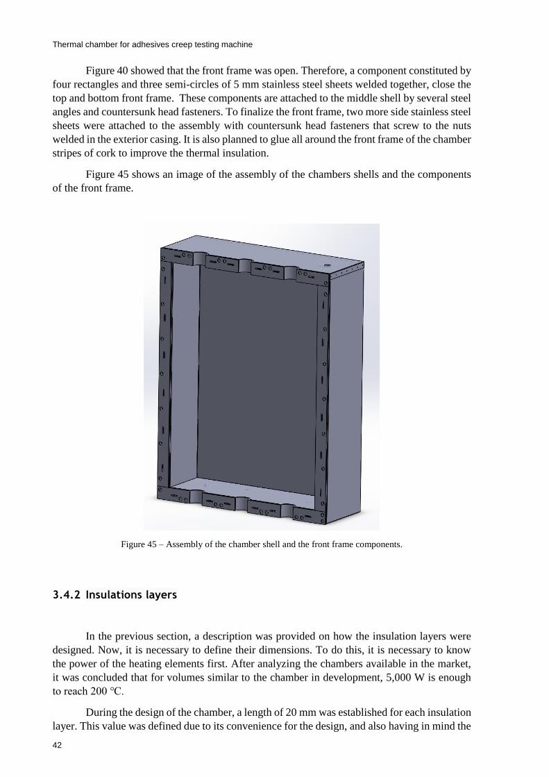
Thermal chamber for adhesives creep testing machine
42
Figure 40 showed that the front frame was open. Therefore, a component constituted by
four rectangles and three semi-circles of 5 mm stainless steel sheets welded together, close the
top and bottom front frame. These components are attached to the middle shell by several steel
angles and countersunk head fasteners. To finalize the front frame, two more side stainless steel
sheets were attached to the assembly with countersunk head fasteners that screw to the nuts
welded in the exterior casing. It is also planned to glue all around the front frame of the chamber
stripes of cork to improve the thermal insulation.
Figure 45 shows an image of the assembly of the chambers shells and the components
of the front frame.
Figure 45 – Assembly of the chamber shell and the front frame components.
3.4.2 Insulations layers
In the previous section, a description was provided on how the insulation layers were
designed. Now, it is necessary to define their dimensions. To do this, it is necessary to know
the power of the heating elements first. After analyzing the chambers available in the market,
it was concluded that for volumes similar to the chamber in development, 5,000 W is enough
to reach 200 .
During the design of the chamber, a length of 20 mm was established for each insulation
layer. This value was defined due to its convenience for the design, and also having in mind the
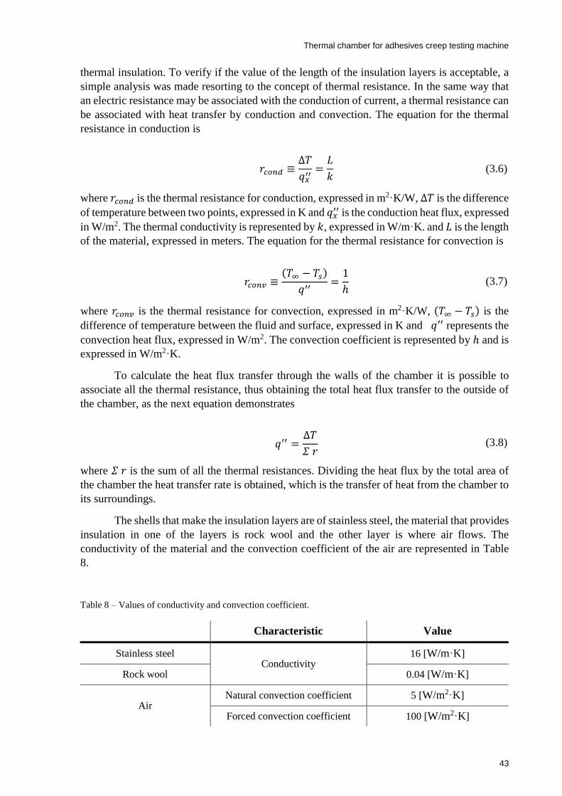
Thermal chamber for adhesives creep testing machine
43
thermal insulation. To verify if the value of the length of the insulation layers is acceptable, a
simple analysis was made resorting to the concept of thermal resistance. In the same way that
an electric resistance may be associated with the conduction of current, a thermal resistance can
be associated with heat transfer by conduction and convection. The equation for the thermal
resistance in conduction is
where 𝑟𝑐𝑜𝑛𝑑 is the thermal resistance for conduction, expressed in m2⸱K/W, ∆𝑇 is the difference
of temperature between two points, expressed in K and 𝑞𝑥′′ is the conduction heat flux, expressed
in W/m2. The thermal conductivity is represented by 𝑘, expressed in W/m⸱K. and 𝐿 is the length
of the material, expressed in meters. The equation for the thermal resistance for convection is
where 𝑟𝑐𝑜𝑛𝑣 is the thermal resistance for convection, expressed in m2⸱K/W, (𝑇∞ − 𝑇𝑠) is the
difference of temperature between the fluid and surface, expressed in K and 𝑞′′ represents the
convection heat flux, expressed in W/m2. The convection coefficient is represented by ℎ and is
expressed in W/m2⸱K.
To calculate the heat flux transfer through the walls of the chamber it is possible to
associate all the thermal resistance, thus obtaining the total heat flux transfer to the outside of
the chamber, as the next equation demonstrates
where 𝛴 𝑟 is the sum of all the thermal resistances. Dividing the heat flux by the total area of
the chamber the heat transfer rate is obtained, which is the transfer of heat from the chamber to
its surroundings.
The shells that make the insulation layers are of stainless steel, the material that provides
insulation in one of the layers is rock wool and the other layer is where air flows. The
conductivity of the material and the convection coefficient of the air are represented in Table
8.
Table 8 – Values of conductivity and convection coefficient.
𝑟𝑐𝑜𝑛𝑑 ≡∆𝑇
𝑞𝑥′′
=𝐿
𝑘 (3.6)
𝑟𝑐𝑜𝑛𝑣 ≡(𝑇∞ − 𝑇𝑠)
𝑞′′=
1
ℎ (3.7)
𝑞′′ =∆𝑇
𝛴 𝑟 (3.8)
Characteristic Value
Stainless steel Conductivity
16 [W/m⸱K]
Rock wool 0.04 [W/m⸱K]
Air Natural convection coefficient 5 [W/m2⸱K]
Forced convection coefficient 100 [W/m2⸱K]
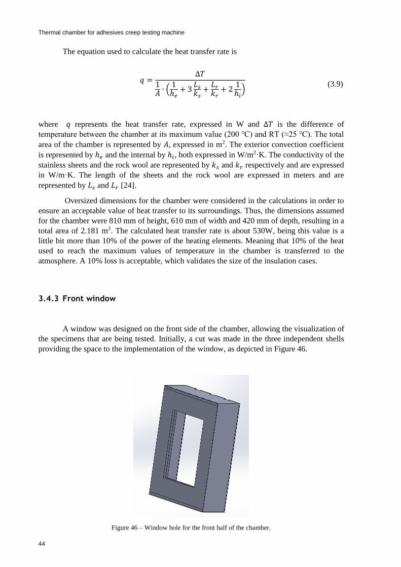
Thermal chamber for adhesives creep testing machine
44
The equation used to calculate the heat transfer rate is
where 𝑞 represents the heat transfer rate, expressed in W and ∆𝑇 is the difference of
temperature between the chamber at its maximum value (200 ) and RT (≈25 ). The total
area of the chamber is represented by 𝐴, expressed in m2. The exterior convection coefficient
is represented by ℎ𝑒 and the internal by ℎ𝑖, both expressed in W/m2⸱K. The conductivity of the
stainless sheets and the rock wool are represented by 𝑘𝑠 and 𝑘𝑟 respectively and are expressed
in W/m⸱K. The length of the sheets and the rock wool are expressed in meters and are
represented by 𝐿𝑠 and 𝐿𝑟 [24].
Oversized dimensions for the chamber were considered in the calculations in order to
ensure an acceptable value of heat transfer to its surroundings. Thus, the dimensions assumed
for the chamber were 810 mm of height, 610 mm of width and 420 mm of depth, resulting in a
total area of 2.181 m2. The calculated heat transfer rate is about 530W, being this value is a
little bit more than 10% of the power of the heating elements. Meaning that 10% of the heat
used to reach the maximum values of temperature in the chamber is transferred to the
atmosphere. A 10% loss is acceptable, which validates the size of the insulation cases.
3.4.3 Front window
A window was designed on the front side of the chamber, allowing the visualization of
the specimens that are being tested. Initially, a cut was made in the three independent shells
providing the space to the implementation of the window, as depicted in Figure 46.
Figure 46 – Window hole for the front half of the chamber.
𝑞 =
∆𝑇
1𝐴 ∙ (
1ℎ𝑒
+ 3𝐿𝑠
𝑘𝑠+
𝐿𝑟
𝑘𝑟+ 2
1ℎ𝑖
)
(3.9)
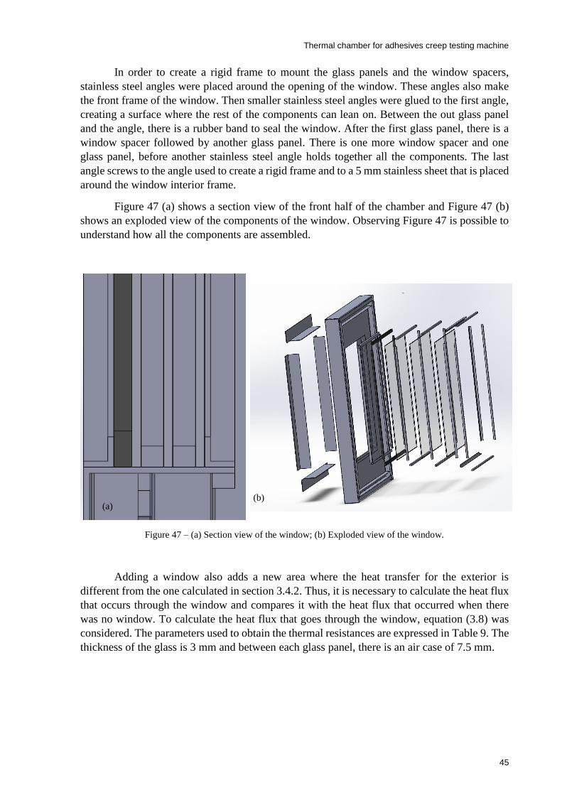
Thermal chamber for adhesives creep testing machine
45
In order to create a rigid frame to mount the glass panels and the window spacers,
stainless steel angles were placed around the opening of the window. These angles also make
the front frame of the window. Then smaller stainless steel angles were glued to the first angle,
creating a surface where the rest of the components can lean on. Between the out glass panel
and the angle, there is a rubber band to seal the window. After the first glass panel, there is a
window spacer followed by another glass panel. There is one more window spacer and one
glass panel, before another stainless steel angle holds together all the components. The last
angle screws to the angle used to create a rigid frame and to a 5 mm stainless sheet that is placed
around the window interior frame.
Figure 47 (a) shows a section view of the front half of the chamber and Figure 47 (b)
shows an exploded view of the components of the window. Observing Figure 47 is possible to
understand how all the components are assembled.
Figure 47 – (a) Section view of the window; (b) Exploded view of the window.
Adding a window also adds a new area where the heat transfer for the exterior is
different from the one calculated in section 3.4.2. Thus, it is necessary to calculate the heat flux
that occurs through the window and compares it with the heat flux that occurred when there
was no window. To calculate the heat flux that goes through the window, equation (3.8) was
considered. The parameters used to obtain the thermal resistances are expressed in Table 9. The
thickness of the glass is 3 mm and between each glass panel, there is an air case of 7.5 mm.
(a) (b)
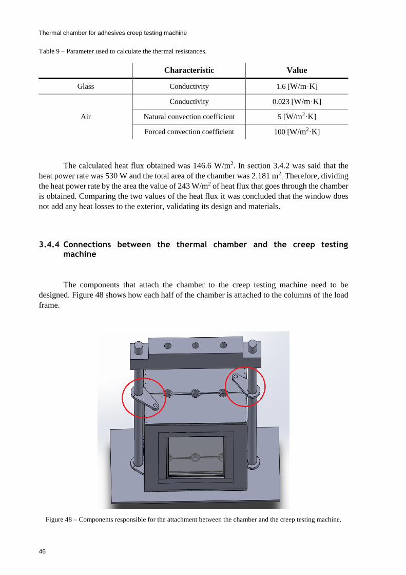
Thermal chamber for adhesives creep testing machine
46
Table 9 – Parameter used to calculate the thermal resistances.
The calculated heat flux obtained was 146.6 W/m2. In section 3.4.2 was said that the
heat power rate was 530 W and the total area of the chamber was 2.181 m2. Therefore, dividing
the heat power rate by the area the value of 243 W/m2 of heat flux that goes through the chamber
is obtained. Comparing the two values of the heat flux it was concluded that the window does
not add any heat losses to the exterior, validating its design and materials.
3.4.4 Connections between the thermal chamber and the creep testing machine
The components that attach the chamber to the creep testing machine need to be
designed. Figure 48 shows how each half of the chamber is attached to the columns of the load
frame.
Figure 48 – Components responsible for the attachment between the chamber and the creep testing machine.
Characteristic Value
Glass Conductivity 1.6 [W/m⸱K]
Air
Conductivity 0.023 [W/m⸱K]
Natural convection coefficient 5 [W/m2⸱K]
Forced convection coefficient 100 [W/m2⸱K]

Thermal chamber for adhesives creep testing machine
47
To create this mechanical connection, a base plate (made of a machined block of
aluminum) was screwed to the structural profiles on the top and the bottom of each half of the
chamber, as is depicted in Figure 49 (a). Then, a custom made shaft – Figure 49 (b) – is screwed
to the base plate, ensuring that the chamber and the cranks pivot together. The other end of the
crank involves around the column of the load frame, also ensuring that they pivot.
Figure 49 – (a) Base plate screwed to the structural profile; (b) Scheme of the custom made shaft.
Figure 50 shows an exploded view of the different elements that compose the crank.
The elements 1 and 2 of Figure 50 are bushings, elements 3 are spacers to ensure that when the
element 4 and 5 (the crank itself) are screwed together around the column this component can
pivot. The bushing 2 needs to have a slot to be placed around the column.
Figure 50 – Component of the crank.
Element that
allows the
crank to pivot
Element that
operate as a
spacer
Threaded
element (b) (a)
1
2
3
5
4

Thermal chamber for adhesives creep testing machine
48
On the bottom of the load frame, there is a table where two spacers (one for each half
of the chamber) hold both halves of the chamber, as depicted in Figure 51 (a). Figure 51 (b)
shows an exploded view of one of the spacers. The spacers have two halves that are screwed
to each other and a washer that creates a smooth surface for the chamber pivot. This washer
also needs to have a slot to be placed around the column.
Figure 51 – (a) Detail of the spacer; (b) exploded view of the spacer.
3.4.5 Back half
In the back half of the chamber a panel, where some components were installed, namely
the motors of the fans for the heating elements, the valves of the cooling system, the protective
equipment, the temperature controller and the switches was created. At the same time, three
holes in all shells of the back half of the chamber were made. Two are needed to allow the shaft
of the fans of the heating elements to go through the shells, while the other, in the center, is to
exhausts the coolant. In the exterior casing, two holes from where two fans blow air to one of
the insulation layers were also made. An electrical enclosure was also predicted to
accommodate the temperature controller and the switches.
Figure 52 depicts the back panel and some of the holes made in the back half of the
chamber.
(b) (a)
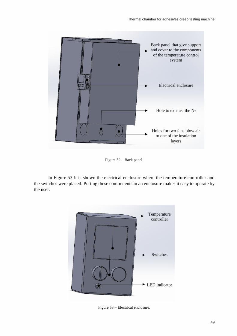
Thermal chamber for adhesives creep testing machine
49
Figure 52 – Back panel.
In Figure 53 It is shown the electrical enclosure where the temperature controller and
the switches were placed. Putting these components in an enclosure makes it easy to operate by
the user.
Figure 53 – Electrical enclosure.
Back panel that give support
and cover to the components
of the temperature control
system
Electrical enclosure
Hole to exhaust the N2
Holes for two fans blow air
to one of the insulation
layers
Temperature
controller
Switches
LED indicator

Thermal chamber for adhesives creep testing machine
50
3.5 Discussion
Chapter 3 presented the design of the thermal chamber and the heat insulators. The main
goal of the heat insulators is to reduce the temperature that reaches the load cells. To achieve
this, two distinct designs were explored and several iterations were made before achieving the
final solution, which was validated by a thermal simulation run in SolidWorks. The results
obtained showed that the temperature that reaches the load cells is in their nominal range.
Subsequently, the different solutions for the design of the thermal chamber were
presented, as well as their advantages and limitations. The design that splits vertically the
chamber into two halves was adopted. Then, a description of the different stages that lead to
the final designed was presented. When convenient, a mathematical explanation supporting
some configurations of the chamber was presented. Also, the mechanical connections that allow
the chamber to pivot were made and explained.
Finally, a panel was designed to be attached to the back half of the chamber to assemble
various components and an electrical enclosure for the temperature controller and for the
switches was created.
Thermal chamber for adhesives creep testing machine
51
4 Control and command
In this chapter, the necessary elements to control the temperature in the thermal chamber
are presented. Then, the electric components are selected and the control circuit is designed.
4.1 Temperature control
For controlling the temperature in the thermal chamber the following elements are used:
Temperature controller;
Cooling and heating elements;
Interface temperature controller/cooling and heating elements;
Temperature sensor;
Figure 54 depicts the way the components are connected. The temperature controller
receives a temperature setpoint from the user and information about the real temperature in the
chamber, measured by the temperature sensor. Based on these data and some suitable control
law, it generates a control action that is then applied to the heating and cooling elements through
some appropriate interface. These elements actuate over the chamber by cooling or heating the
volume of air inside it [27].
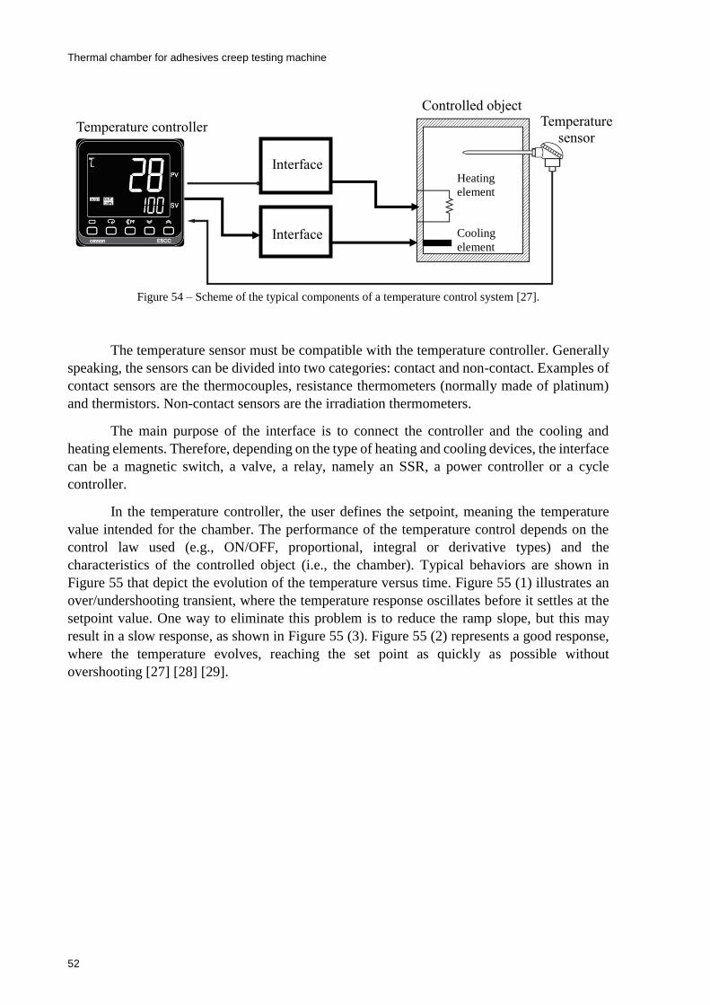
Thermal chamber for adhesives creep testing machine
52
Figure 54 – Scheme of the typical components of a temperature control system [27].
The temperature sensor must be compatible with the temperature controller. Generally
speaking, the sensors can be divided into two categories: contact and non-contact. Examples of
contact sensors are the thermocouples, resistance thermometers (normally made of platinum)
and thermistors. Non-contact sensors are the irradiation thermometers.
The main purpose of the interface is to connect the controller and the cooling and
heating elements. Therefore, depending on the type of heating and cooling devices, the interface
can be a magnetic switch, a valve, a relay, namely an SSR, a power controller or a cycle
controller.
In the temperature controller, the user defines the setpoint, meaning the temperature
value intended for the chamber. The performance of the temperature control depends on the
control law used (e.g., ON/OFF, proportional, integral or derivative types) and the
characteristics of the controlled object (i.e., the chamber). Typical behaviors are shown in
Figure 55 that depict the evolution of the temperature versus time. Figure 55 (1) illustrates an
over/undershooting transient, where the temperature response oscillates before it settles at the
setpoint value. One way to eliminate this problem is to reduce the ramp slope, but this may
result in a slow response, as shown in Figure 55 (3). Figure 55 (2) represents a good response,
where the temperature evolves, reaching the set point as quickly as possible without
overshooting [27] [28] [29].
Interface
Temperature controller Temperature
sensor
Controlled object
Heating
element
Cooling
element
Interface
Interface
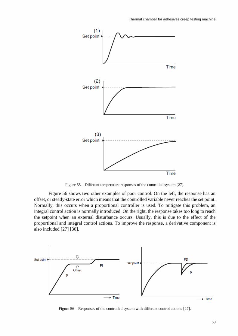
Thermal chamber for adhesives creep testing machine
53
Figure 55 – Different temperature responses of the controlled system [27].
Figure 56 shows two other examples of poor control. On the left, the response has an
offset, or steady-state error which means that the controlled variable never reaches the set point.
Normally, this occurs when a proportional controller is used. To mitigate this problem, an
integral control action is normally introduced. On the right, the response takes too long to reach
the setpoint when an external disturbance occurs. Usually, this is due to the effect of the
proportional and integral control actions. To improve the response, a derivative component is
also included [27] [30].
Figure 56 – Responses of the controlled system with different control actions [27].
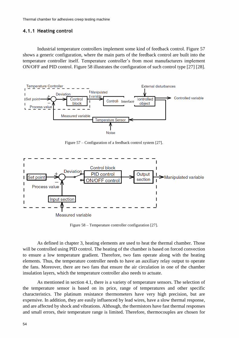
Thermal chamber for adhesives creep testing machine
54
4.1.1 Heating control
Industrial temperature controllers implement some kind of feedback control. Figure 57
shows a generic configuration, where the main parts of the feedback control are built into the
temperature controller itself. Temperature controller’s from most manufacturers implement
ON/OFF and PID control. Figure 58 illustrates the configuration of such control type [27] [28].
Figure 57 – Configuration of a feedback control system [27].
Figure 58 – Temperature controller configuration [27].
As defined in chapter 3, heating elements are used to heat the thermal chamber. Those
will be controlled using PID control. The heating of the chamber is based on forced convection
to ensure a low temperature gradient. Therefore, two fans operate along with the heating
elements. Thus, the temperature controller needs to have an auxiliary relay output to operate
the fans. Moreover, there are two fans that ensure the air circulation in one of the chamber
insulation layers, which the temperature controller also needs to actuate.
As mentioned in section 4.1, there is a variety of temperature sensors. The selection of
the temperature sensor is based on its price, range of temperatures and other specific
characteristics. The platinum resistance thermometers have very high precision, but are
expensive. In addition, they are easily influenced by lead wires, have a slow thermal response,
and are affected by shock and vibrations. Although, the thermistors have fast thermal responses
and small errors, their temperature range is limited. Therefore, thermocouples are chosen for
Interface

Thermal chamber for adhesives creep testing machine
55
measuring the chamber temperature, since they have a broad measurement range, have high
resistance to shock and vibrations, and have a fast thermal response [27].
4.1.2 Cooling control
Although the cooling and heating elements are different, the cooling control relies on
the same principle of the heating control: a feedback control system – Figure 57. The cooling
of the chamber uses a cryogenic coolant and a cryogenic solenoid to control the injection of the
coolant in the chamber. The valve has two positions: totally open and totally closed. Hence an
ON/OFF control action is necessary to command the valve.
Figure 59 shows the typical response to an ON/OFF control action. Interpreting the
Figure 59 as the cooling control, when the control action is set to ON, the cryogenic solenoid
valve is totally open, letting the coolant enter the chamber. As soon as the temperature sensor
detects a temperature value lower than the setpoint, the controller sets the control action to OFF,
closing the cryogenic solenoid valve. At this point, no more coolant enters in the chamber. The
remaining coolant in the chamber is slowly exhausted and the temperature inside the chamber
starts to rise until and then exceeds the set point. When the temperature sensor detects that the
effective temperature is higher than the setpoint, it sends again a signal to the controller, which
sets once more the control action to ON. These cycles perpetuate for as long as needed.
Figure 59 – Response to an ON/OFF control [31].
The fans used in the heating control to homogenize the temperature inside the chamber
are also used in the cooling. To ensure reduced temperature gradients, the entry points of the
coolant in the inner volume of the chamber are distributed.
The temperature sensor used for the heating control is the same as for the cooling
control, since thermocouples have a wide range of temperatures they can operate.
Figure 60 shows a scheme of the main components of the cooling method. At the end
of the vessel containing L-N2, is a pressure reducer valve that controls the pressure in the pipes.
Then, a directional control valve (in this case a cryogenic valve), commanded by a solenoid,
allows or blocks the passage of the coolant to the injectors inside the chamber. At the derivation
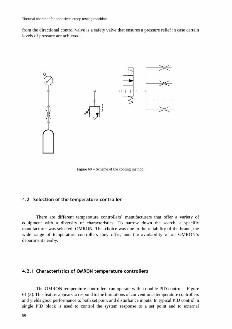
Thermal chamber for adhesives creep testing machine
56
from the directional control valve is a safety valve that ensures a pressure relief in case certain
levels of pressure are achieved.
Figure 60 – Scheme of the cooling method.
4.2 Selection of the temperature controller
There are different temperature controllers’ manufacturers that offer a variety of
equipment with a diversity of characteristics. To narrow down the search, a specific
manufacturer was selected: OMRON. This choice was due to the reliability of the brand, the
wide range of temperature controllers they offer, and the availability of an OMRON’s
department nearby.
4.2.1 Characteristics of OMRON temperature controllers
The OMRON temperature controllers can operate with a double PID control – Figure
61 (3). This feature appears to respond to the limitations of conventional temperature controllers
and yields good performance to both set point and disturbance inputs. In typical PID control, a
single PID block is used to control the system response to a set point and to external

Thermal chamber for adhesives creep testing machine
57
disturbances. Therefore, if good response to external disturbances is desired, then poor response
to the setpoint may be obtained – Figure 61 (1). On the other hand, if good response to the
setpoint is intended, then bad response to external disturbances can result – Figure 61 (2) [27].
Figure 61 – System response with one PID and two PID controllers [27].
Whatever the case, to ensure good temperature control, the PID constants need to be
adjusted properly. This can be done manually or automatically, through auto-tuning and self-
tuning. The most common methods used for auto-tuning are the step response and the limit
cycle methods.
A PID controller outputs a continuous control action between 0% and 100% of its signal
range, contrasting with the ON/OFF control mode that outputs just 100% (ON) or 0% (OFF).
The OMROM temperature controllers can implement both control modes. To implement PID
control, the temperature controller uses time-proportional control action, which allows control
output values between 0% and 100%. The controller output is then applied to the actuation
elements via a relay or SSR.
When using time-proportional control a time parameter has to be defined, denoted by
control period. Generically, it is necessary to set the control action to ON during a certain
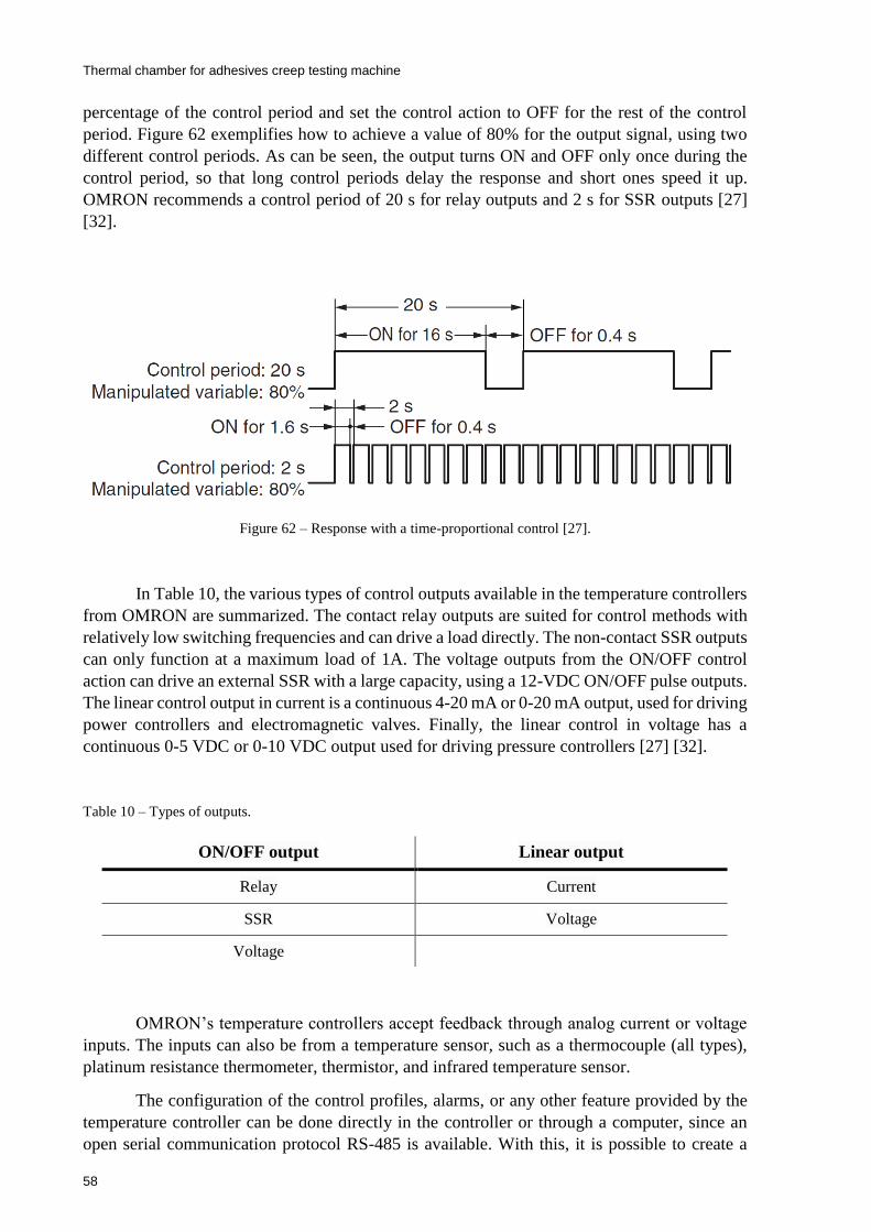
Thermal chamber for adhesives creep testing machine
58
percentage of the control period and set the control action to OFF for the rest of the control
period. Figure 62 exemplifies how to achieve a value of 80% for the output signal, using two
different control periods. As can be seen, the output turns ON and OFF only once during the
control period, so that long control periods delay the response and short ones speed it up.
OMRON recommends a control period of 20 s for relay outputs and 2 s for SSR outputs [27]
[32].
Figure 62 – Response with a time-proportional control [27].
In Table 10, the various types of control outputs available in the temperature controllers
from OMRON are summarized. The contact relay outputs are suited for control methods with
relatively low switching frequencies and can drive a load directly. The non-contact SSR outputs
can only function at a maximum load of 1A. The voltage outputs from the ON/OFF control
action can drive an external SSR with a large capacity, using a 12-VDC ON/OFF pulse outputs.
The linear control output in current is a continuous 4-20 mA or 0-20 mA output, used for driving
power controllers and electromagnetic valves. Finally, the linear control in voltage has a
continuous 0-5 VDC or 0-10 VDC output used for driving pressure controllers [27] [32].
Table 10 – Types of outputs.
OMRON’s temperature controllers accept feedback through analog current or voltage
inputs. The inputs can also be from a temperature sensor, such as a thermocouple (all types),
platinum resistance thermometer, thermistor, and infrared temperature sensor.
The configuration of the control profiles, alarms, or any other feature provided by the
temperature controller can be done directly in the controller or through a computer, since an
open serial communication protocol RS-485 is available. With this, it is possible to create a
ON/OFF output Linear output
Relay Current
SSR Voltage
Voltage
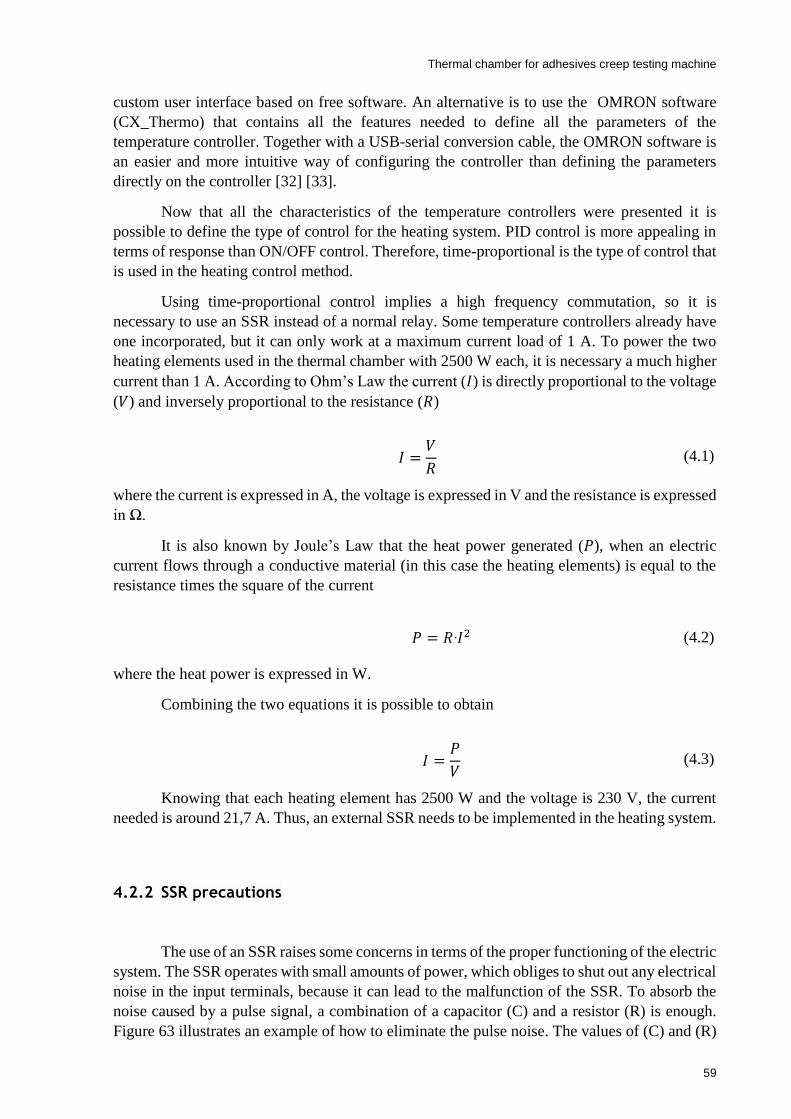
Thermal chamber for adhesives creep testing machine
59
custom user interface based on free software. An alternative is to use the OMRON software
(CX_Thermo) that contains all the features needed to define all the parameters of the
temperature controller. Together with a USB-serial conversion cable, the OMRON software is
an easier and more intuitive way of configuring the controller than defining the parameters
directly on the controller [32] [33].
Now that all the characteristics of the temperature controllers were presented it is
possible to define the type of control for the heating system. PID control is more appealing in
terms of response than ON/OFF control. Therefore, time-proportional is the type of control that
is used in the heating control method.
Using time-proportional control implies a high frequency commutation, so it is
necessary to use an SSR instead of a normal relay. Some temperature controllers already have
one incorporated, but it can only work at a maximum current load of 1 A. To power the two
heating elements used in the thermal chamber with 2500 W each, it is necessary a much higher
current than 1 A. According to Ohm’s Law the current (𝐼) is directly proportional to the voltage
(𝑉) and inversely proportional to the resistance (𝑅)
where the current is expressed in A, the voltage is expressed in V and the resistance is expressed
in Ω.
It is also known by Joule’s Law that the heat power generated (𝑃), when an electric
current flows through a conductive material (in this case the heating elements) is equal to the
resistance times the square of the current
where the heat power is expressed in W.
Combining the two equations it is possible to obtain
Knowing that each heating element has 2500 W and the voltage is 230 V, the current
needed is around 21,7 A. Thus, an external SSR needs to be implemented in the heating system.
4.2.2 SSR precautions
The use of an SSR raises some concerns in terms of the proper functioning of the electric
system. The SSR operates with small amounts of power, which obliges to shut out any electrical
noise in the input terminals, because it can lead to the malfunction of the SSR. To absorb the
noise caused by a pulse signal, a combination of a capacitor (C) and a resistor (R) is enough.
Figure 63 illustrates an example of how to eliminate the pulse noise. The values of (C) and (R)
𝐼 =𝑉
𝑅 (4.1)
𝑃 = 𝑅⸱𝐼2 (4.2)
𝐼 =𝑃
𝑉 (4.3)
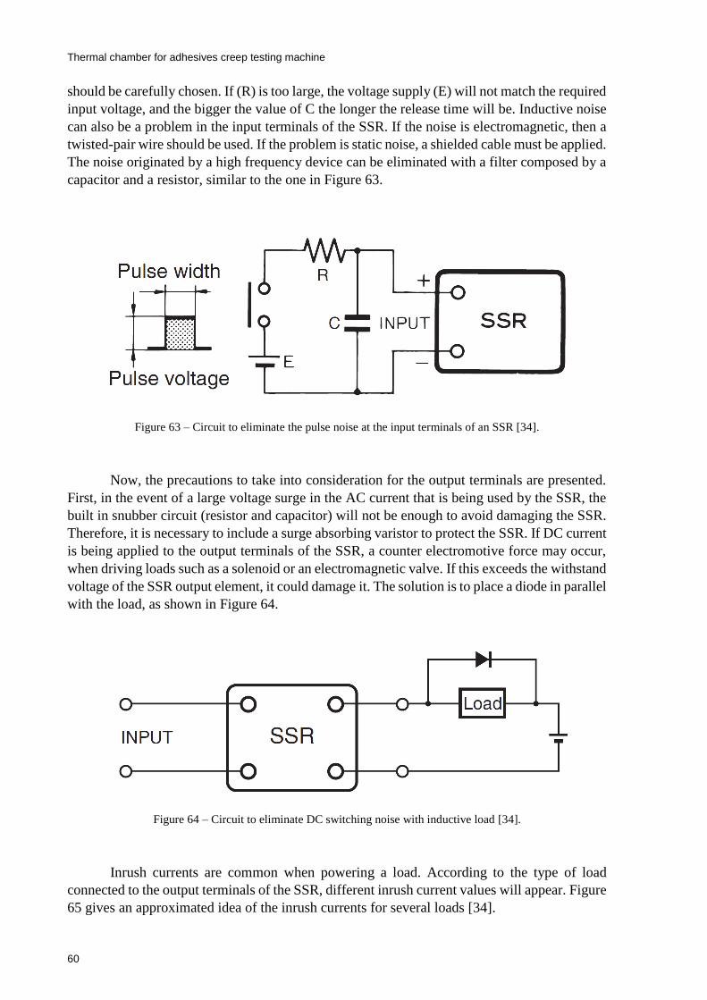
Thermal chamber for adhesives creep testing machine
60
should be carefully chosen. If (R) is too large, the voltage supply (E) will not match the required
input voltage, and the bigger the value of C the longer the release time will be. Inductive noise
can also be a problem in the input terminals of the SSR. If the noise is electromagnetic, then a
twisted-pair wire should be used. If the problem is static noise, a shielded cable must be applied.
The noise originated by a high frequency device can be eliminated with a filter composed by a
capacitor and a resistor, similar to the one in Figure 63.
Figure 63 – Circuit to eliminate the pulse noise at the input terminals of an SSR [34].
Now, the precautions to take into consideration for the output terminals are presented.
First, in the event of a large voltage surge in the AC current that is being used by the SSR, the
built in snubber circuit (resistor and capacitor) will not be enough to avoid damaging the SSR.
Therefore, it is necessary to include a surge absorbing varistor to protect the SSR. If DC current
is being applied to the output terminals of the SSR, a counter electromotive force may occur,
when driving loads such as a solenoid or an electromagnetic valve. If this exceeds the withstand
voltage of the SSR output element, it could damage it. The solution is to place a diode in parallel
with the load, as shown in Figure 64.
Figure 64 – Circuit to eliminate DC switching noise with inductive load [34].
Inrush currents are common when powering a load. According to the type of load
connected to the output terminals of the SSR, different inrush current values will appear. Figure
65 gives an approximated idea of the inrush currents for several loads [34].

Thermal chamber for adhesives creep testing machine
61
Figure 65 – Inrush current values compared with their normal current for different loads [34].
4.2.3 Selection of the OMRON controller
The temperature controller required for this system needs to fulfill the following
conditions:
Universal input for a thermocouple ;
Relay output control to command the cryogenic valve;
Voltage output control for driving an SSR;
Auxiliary relay output control for the fans;
Able to define set points and heating/cooling curves;
Compatible with 220-240 VAC, 50 Hz power supply;
The device selected is the industrial temperature controller E5CC-TQX3 A5 M-000,
because it complies with all the requested conditions. It has a universal input for different
temperature sensors, including for thermocouples. The control output #1 is a voltage output for
driving an external SSR, the control output #2 is an auxiliary relay output. The other two
auxiliary outputs are used to command the fans. The temperature controller has the ability to
define set points and heating/cooling curves and operates between 100-240 VAC [32].
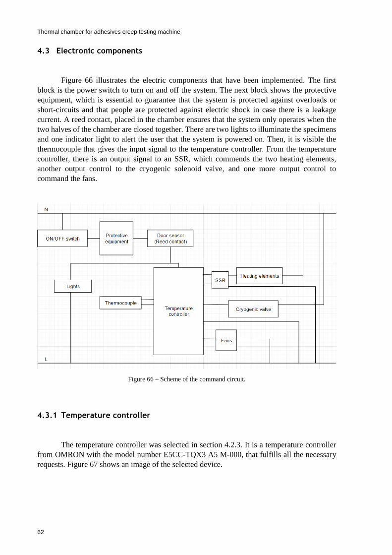
Thermal chamber for adhesives creep testing machine
62
4.3 Electronic components
Figure 66 illustrates the electric components that have been implemented. The first
block is the power switch to turn on and off the system. The next block shows the protective
equipment, which is essential to guarantee that the system is protected against overloads or
short-circuits and that people are protected against electric shock in case there is a leakage
current. A reed contact, placed in the chamber ensures that the system only operates when the
two halves of the chamber are closed together. There are two lights to illuminate the specimens
and one indicator light to alert the user that the system is powered on. Then, it is visible the
thermocouple that gives the input signal to the temperature controller. From the temperature
controller, there is an output signal to an SSR, which commends the two heating elements,
another output control to the cryogenic solenoid valve, and one more output control to
command the fans.
Figure 66 – Scheme of the command circuit.
4.3.1 Temperature controller
The temperature controller was selected in section 4.2.3. It is a temperature controller
from OMRON with the model number E5CC-TQX3 A5 M-000, that fulfills all the necessary
requests. Figure 67 shows an image of the selected device.
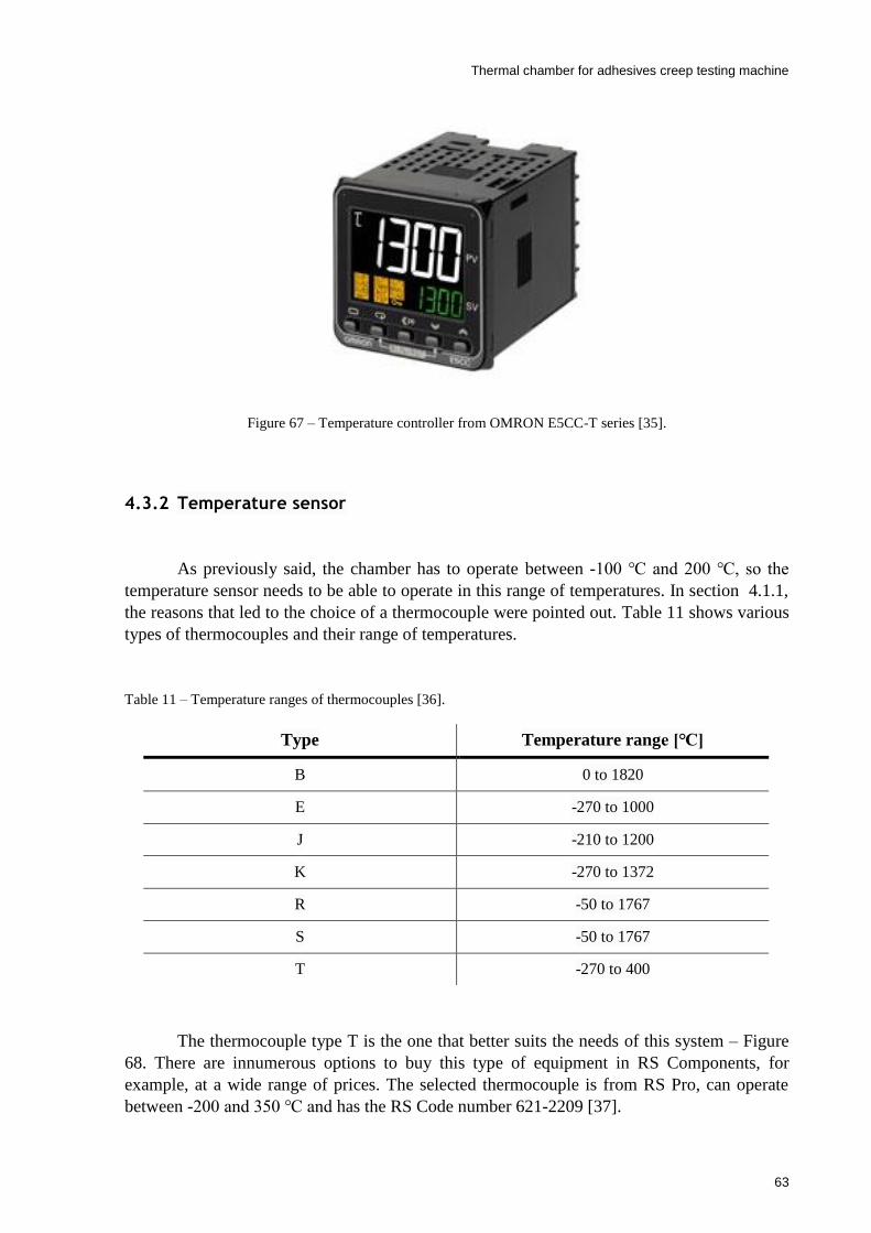
Thermal chamber for adhesives creep testing machine
63
Figure 67 – Temperature controller from OMRON E5CC-T series [35].
4.3.2 Temperature sensor
As previously said, the chamber has to operate between -100 and 200 , so the
temperature sensor needs to be able to operate in this range of temperatures. In section 4.1.1,
the reasons that led to the choice of a thermocouple were pointed out. Table 11 shows various
types of thermocouples and their range of temperatures.
Table 11 – Temperature ranges of thermocouples [36].
The thermocouple type T is the one that better suits the needs of this system – Figure
68. There are innumerous options to buy this type of equipment in RS Components, for
example, at a wide range of prices. The selected thermocouple is from RS Pro, can operate
between -200 and 350 and has the RS Code number 621-2209 [37].
Type Temperature range []
B 0 to 1820
E -270 to 1000
J -210 to 1200
K -270 to 1372
R -50 to 1767
S -50 to 1767
T -270 to 400

Thermal chamber for adhesives creep testing machine
64
Figure 68 – Thermocouple type T [37].
4.3.3 SSR
The SSR needs to have an input voltage of 12 VDC. The two heating elements are
powered at 220-240 VAC, so the output voltage of the SSR has to be the same. It is also
necessary to ensure that the current load admissible at the SSR terminals is superior to the one
that powers the heating elements. The calculations of the current load were made in section
4.2.1, resulting in a value of around 21.7 A.
The G3NA-225B-UTU DC5-24 from OMRON – Figure 69 – was selected. This SSR
has an input operating voltage range of 5-24 VDC and a load voltage range of 24-240 VAC.
Finally, the maximum load current admissible is 25 A, therefore all the requirements for the
SSR are fulfilled.
As said in section 4.2.2, there are some concerns that should not be overlooked when
using an SSR. In the input terminals, no additional equipment is required, since the SSR has a
built-in snubber. This relay also has a built-in surge absorbing varistor. So, there is no extra
equipment needed to protect the output terminals. Since the load that is being powered is a
resistive one, no inrush currents appear [38].
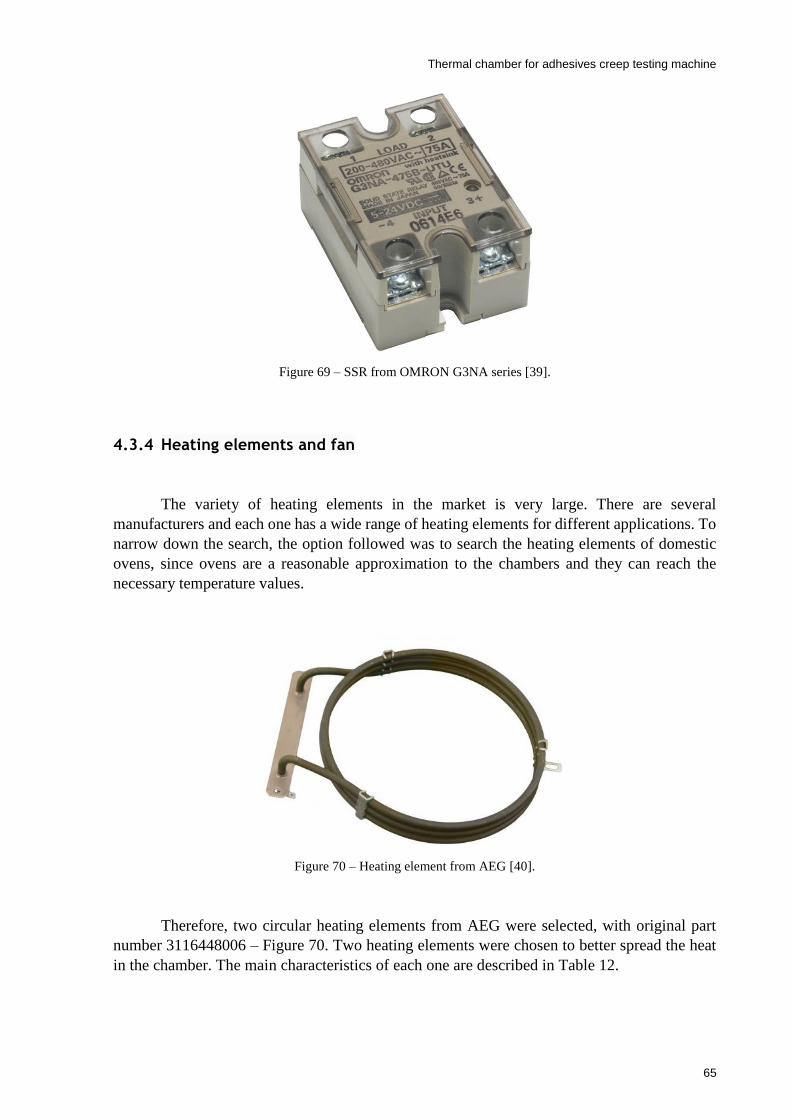
Thermal chamber for adhesives creep testing machine
65
Figure 69 – SSR from OMRON G3NA series [39].
4.3.4 Heating elements and fan
The variety of heating elements in the market is very large. There are several
manufacturers and each one has a wide range of heating elements for different applications. To
narrow down the search, the option followed was to search the heating elements of domestic
ovens, since ovens are a reasonable approximation to the chambers and they can reach the
necessary temperature values.
Figure 70 – Heating element from AEG [40].
Therefore, two circular heating elements from AEG were selected, with original part
number 3116448006 – Figure 70. Two heating elements were chosen to better spread the heat
in the chamber. The main characteristics of each one are described in Table 12.

Thermal chamber for adhesives creep testing machine
66
Table 12 – Heating element characteristics [40].
Another reason to select a heating element from a domestic oven is the facility to find a
fan with an incorporated motor that fits the heating element. So, a motor and fan assembly from
Belling was selected, with original part number 082603745 – Figure 71. The main
characteristics of the assembly are described in Table 13.
Figure 71 – Motor and fan assembly from Belling [41].
Table 13 – Motor and fan assembly characteristics [41] [42].
Characteristic Value
Power 2500 W
Voltage 230-240 V
Height 225 mm
Width 195 mm
Bracket 145 mm
Tags width 90 mm
Characteristic Value
Power 24-28 W
Voltage 220-240 V
Frequency 50/60 Hz
Class CL.180
Diameter of the motor mounting plate 130 mm
Depth of motor mounting plate 60 mm
Diameter of the fan blade 150 mm
Depth of fan blade 22 mm
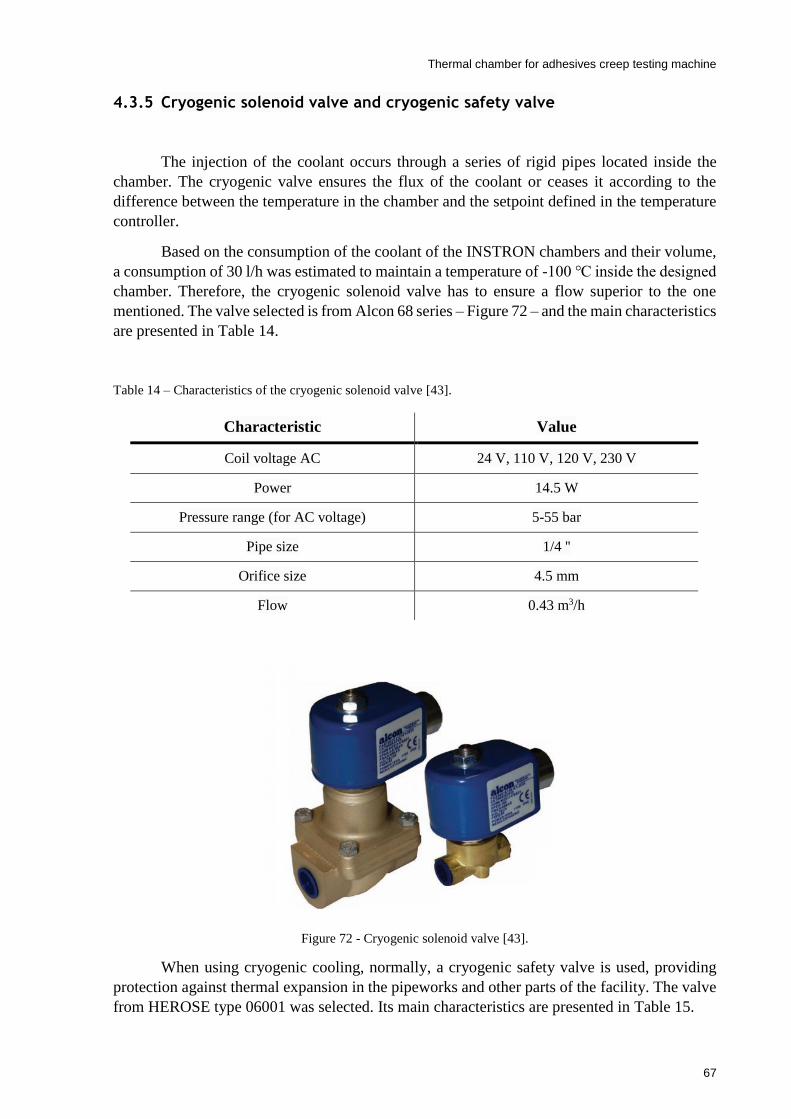
Thermal chamber for adhesives creep testing machine
67
4.3.5 Cryogenic solenoid valve and cryogenic safety valve
The injection of the coolant occurs through a series of rigid pipes located inside the
chamber. The cryogenic valve ensures the flux of the coolant or ceases it according to the
difference between the temperature in the chamber and the setpoint defined in the temperature
controller.
Based on the consumption of the coolant of the INSTRON chambers and their volume,
a consumption of 30 l/h was estimated to maintain a temperature of -100 inside the designed
chamber. Therefore, the cryogenic solenoid valve has to ensure a flow superior to the one
mentioned. The valve selected is from Alcon 68 series – Figure 72 – and the main characteristics
are presented in Table 14.
Table 14 – Characteristics of the cryogenic solenoid valve [43].
Figure 72 - Cryogenic solenoid valve [43].
When using cryogenic cooling, normally, a cryogenic safety valve is used, providing
protection against thermal expansion in the pipeworks and other parts of the facility. The valve
from HEROSE type 06001 was selected. Its main characteristics are presented in Table 15.
Characteristic Value
Coil voltage AC 24 V, 110 V, 120 V, 230 V
Power 14.5 W
Pressure range (for AC voltage) 5-55 bar
Pipe size 1/4 ''
Orifice size 4.5 mm
Flow 0.43 m3/h
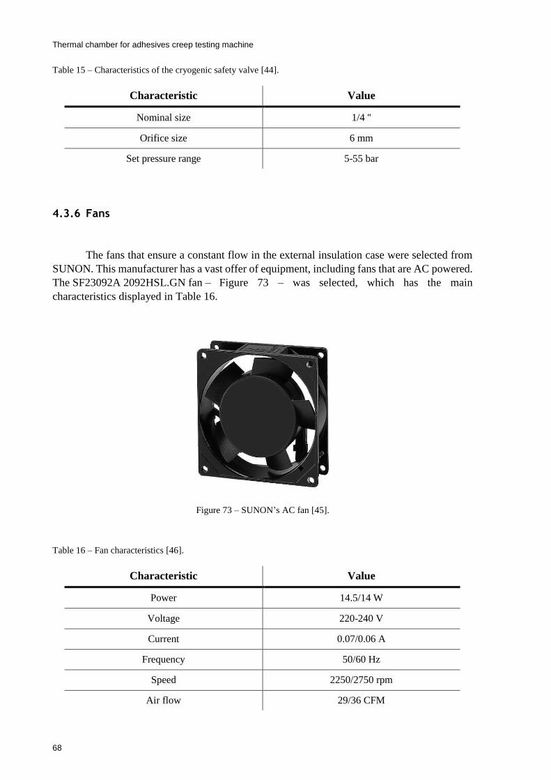
Thermal chamber for adhesives creep testing machine
68
Table 15 – Characteristics of the cryogenic safety valve [44].
4.3.6 Fans
The fans that ensure a constant flow in the external insulation case were selected from
SUNON. This manufacturer has a vast offer of equipment, including fans that are AC powered.
The SF23092A 2092HSL.GN fan – Figure 73 – was selected, which has the main
characteristics displayed in Table 16.
Figure 73 – SUNON’s AC fan [45].
Table 16 – Fan characteristics [46].
Characteristic Value
Nominal size 1/4 ''
Orifice size 6 mm
Set pressure range 5-55 bar
Characteristic Value
Power 14.5/14 W
Voltage 220-240 V
Current 0.07/0.06 A
Frequency 50/60 Hz
Speed 2250/2750 rpm
Air flow 29/36 CFM
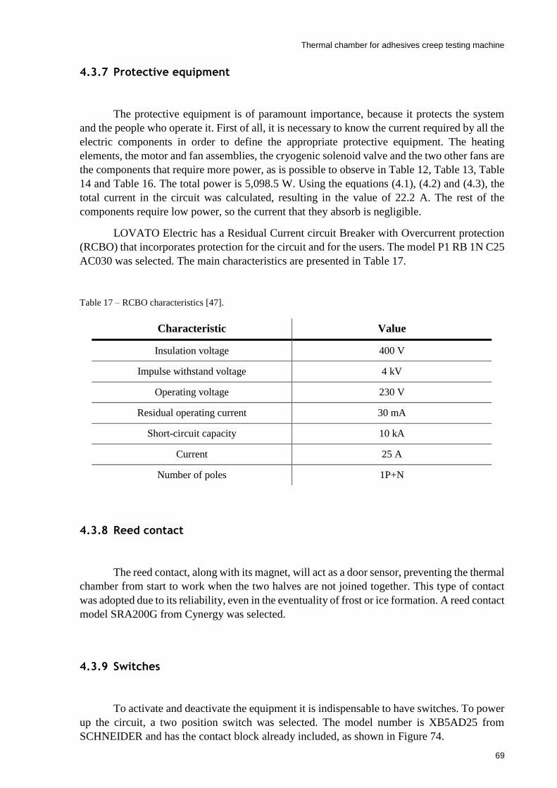
Thermal chamber for adhesives creep testing machine
69
4.3.7 Protective equipment
The protective equipment is of paramount importance, because it protects the system
and the people who operate it. First of all, it is necessary to know the current required by all the
electric components in order to define the appropriate protective equipment. The heating
elements, the motor and fan assemblies, the cryogenic solenoid valve and the two other fans are
the components that require more power, as is possible to observe in Table 12, Table 13, Table
14 and Table 16. The total power is 5,098.5 W. Using the equations (4.1), (4.2) and (4.3), the
total current in the circuit was calculated, resulting in the value of 22.2 A. The rest of the
components require low power, so the current that they absorb is negligible.
LOVATO Electric has a Residual Current circuit Breaker with Overcurrent protection
(RCBO) that incorporates protection for the circuit and for the users. The model P1 RB 1N C25
AC030 was selected. The main characteristics are presented in Table 17.
Table 17 – RCBO characteristics [47].
4.3.8 Reed contact
The reed contact, along with its magnet, will act as a door sensor, preventing the thermal
chamber from start to work when the two halves are not joined together. This type of contact
was adopted due to its reliability, even in the eventuality of frost or ice formation. A reed contact
model SRA200G from Cynergy was selected.
4.3.9 Switches
To activate and deactivate the equipment it is indispensable to have switches. To power
up the circuit, a two position switch was selected. The model number is XB5AD25 from
SCHNEIDER and has the contact block already included, as shown in Figure 74.
Characteristic Value
Insulation voltage 400 V
Impulse withstand voltage 4 kV
Operating voltage 230 V
Residual operating current 30 mA
Short-circuit capacity 10 kA
Current 25 A
Number of poles 1P+N

Thermal chamber for adhesives creep testing machine
70
Figure 74 – Two position switch [48].
Another switch is necessary to turn on and off the lights inside the chamber. Therefore,
a pushbutton with a normally open and a normally closed contact was selected from
SCHNEIDER, that has the contact block already incorporated. The model number is
XB4BW3165 – Figure 75 – and has a LED light incorporated.
Figure 75 – Pushbutton.
4.3.10 Lights
The indicator lights give a visual feedback that the equipment is working. There is a big
variety of these components with different possibilities of color, type of operating current, type
of terminals and so on. A green light indicator that can operate with 220-240 VAC was selected
from RS Pro, with the RS Stock No 700-1946 – Figure 76.
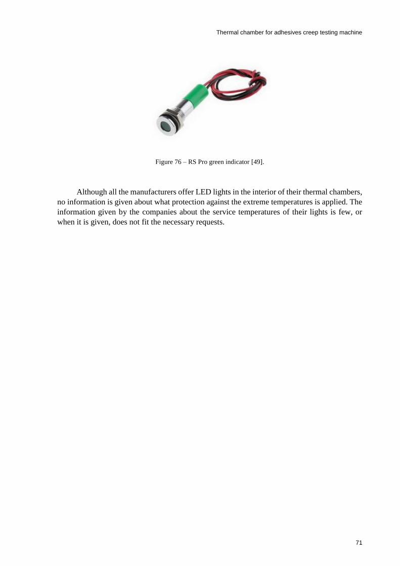
Thermal chamber for adhesives creep testing machine
71
Figure 76 – RS Pro green indicator [49].
Although all the manufacturers offer LED lights in the interior of their thermal chambers,
no information is given about what protection against the extreme temperatures is applied. The
information given by the companies about the service temperatures of their lights is few, or
when it is given, does not fit the necessary requests.

Thermal chamber for adhesives creep testing machine
72
4.4 Electric circuit
4.4.1 Power circuit
The power circuit is presented.
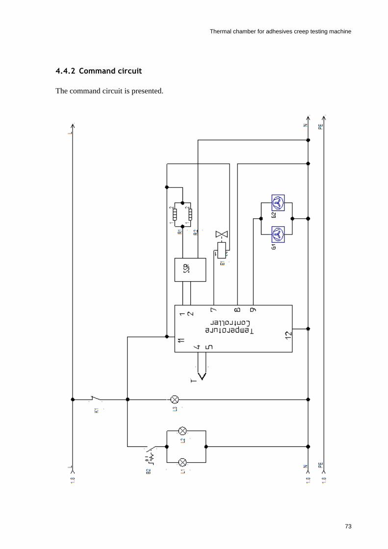
Thermal chamber for adhesives creep testing machine
73
4.4.2 Command circuit
The command circuit is presented.
Thermal chamber for adhesives creep testing machine
74
4.5 Discussions
Chapter 4 presented the control of the temperature chamber. When designing a system
like this, it is important to define how the heating and cooling is going to be performed. From
there, it is possible to define the appropriate type of control that is going to be adopted. At the
same time, it is fundamental to know the limitations and advantages of each type of control and
to implement the one that better suits the needs of the system.
Selecting the temperature controller is a critical step, because this device is the core of
the system. It has to fulfill all the needs of the heating and cooling functions and also
accommodate the complementary components that compose the system.
The selection of all the components was made, trying to find the best solution for the
equipment in terms of quality and performance. The command circuit was completely defined
Thermal chamber for adhesives creep testing machine
75
5 Conclusions
5.1 Conclusions
The market demand for thermal chambers for multi-station creep testing machines is
very low. Therefore, the few solutions that some manufacturers offer are expensive and not
suitable for models different from those they commercialize. This raised the need for designing
a thermal chamber for the three-station creep testing machine of the AJUP.
The main goal of this dissertation was to design a thermal chamber that operates
between -100 and 200 . The chamber has to be capable of performing temperature tests
automatically.
In a first stage, the commercial solutions of thermal chambers for creep testing machines
were analyzed and the designs that enable its incorporation were understood. The heating and
cooling solutions were studied to better perceive how the thermal chambers operate.
On the top of the creep testing machine of the AJUP, there are three load cells that have
a service temperature of -20 and 70 . The temperature values that reach the load cells when
the chamber is operating in its extreme values exceed the range of the service temperature.
Thus, it was necessary to develop a heat insulator, which reduces the temperature values applied
to the load cells. Two different designs were explored, trying not only to reach the service
temperature values, but also the temperature nominal range. Along with the development of the
heat insulator, the designs suffered several iterations that discredited or validated alternative
solutions after thermal simulation in SolidWorks.
The next step was to design the chamber. There were different approaches on how to
design it, but the followed solution was the one in which the chamber is split vertically in two
halves and each half is attached to one of the columns of the load frame. This attachment is
made by a crank that allows the chamber to pivot with the column. The evolution of the design
was presented and mathematical justifications were given for some relevant options in terms of
thermal efficiency of the chamber. In the back half of the chamber, a panel was designed to
accommodate several components of the temperature control system.
In the last stage, the temperature control system was presented and the heating and the
cooling methods were described. Then, the temperature controller was selected. After selecting
Thermal chamber for adhesives creep testing machine
76
the controller the different electric components were defined based on the needs of the chamber
and the temperature controller. At the end, the power and command circuit were defined.
The chamber was designed and its temperature control system was defined concretizing
the main goals of the dissertation.
The article “Thermal chamber for adhesives multi-station creep testing machine” was
submitted to the U.Porto Journal of Engineering.
5.2 Future development
A thermal simulation with all the components of the chamber should be run to confirm
the calculations made in terms of thermal efficiency. Ideally, the thermal simulation should also
have incorporated the creep testing machine. Since the chamber was designed in SolidWorks
and the creep testing machine in SolidEdge there is no recommendation for which software use.
The LED lights that illuminate the specimens need to be defined. It is also interesting
to incorporate a resistance in one of the glass panels of the window. This way during the cooling,
the air on the glass panel does not condensate.

Thermal chamber for adhesives creep testing machine
77
Thermal chamber for adhesives creep testing machine
78
6 References
1. Da Silva, L.F., A. Öchsner, and R.D. Adams, Handbook of adhesion technology. 2011:
Springer Science & Business Media.
2. Freire, H.M., Desenvolvimento de um dispositivo experimental para medir a resistência
à fluência de ligações adesivas. 2015.
3. Pina, L.P.L., Development of a multi-station creep testing machine for adhesive joints.
2016.
4. Silva, E.D.R., Development of a Three-station Creep Machine for Adhesive Joints
Testing. 2018.
5. Kinloch, A.J., Adhesion and adhesives: science and technology. 2012: Springer Science
& Business Media.
6. Adhesives&Selants. Types of Adhesives. 2019; Available from:
https://www.adhesives.org/adhesives-sealants/science-of-adhesion/design-of-
adhesives-bonds/types-of-adhesives.
7. Handbook, M.S., Adhesive Bonding. 1987, MIL-HDBK-691B, US Department of
Defense.
8. Dowling, N.E., Mechanical behavior of materials: engineering methods for
deformation, fracture, and fatigue. 2012: Pearson.
9. Da Silva, L.F., et al., Testing adhesive joints: best practices. 2012: John Wiley & Sons.
10. ZWICK, Creep Testing MachineKappa Multistation for Plastics. 2019.
11. INSTRON, Multi Station Systems 5900 series. 2018.
12. Associação de Laboratórios Acreditados de Portugal, Guia 19. 2004.
13. Pombeiro, A.J.L.O., Técnicas e operações unitárias em química laboratorial. 1983:
Fundação Calouste Gulbenkian.
14. Lefcourt, A., B. Buell, and U.J.A.E.i.A. Tasch, Large environmental chamber: Design
and operating characteristics. 2001. 17(5): p. 691.
15. Leskinen, A., et al., Characterization and testing of a new environmental chamber.
2015.
16. INSTRON, Enviromental Chambers 3119 600 Series. 2017.
17. Berryman, J.G. and W.D. Daily, Optimal joule heating of the subsurface. 1994, Google
Patents.

Thermal chamber for adhesives creep testing machine
79
18. WATTCO. Electric Heating Elements Wattco. 2019; Available from:
https://www.wattco.com/electric-heating-elements/.
19. Handbook, K.J.K.A., Heating Alloys for Electric Household Appliances. 2013.
20. WATTCO, Tubular heaters. 2017.
21. SIGMA, Cryogenic Coling for Temperature Chambers and Thermal Platforms. 2000.
22. Hashmi, S., Comprehensive materials processing. 2014: Newnes.
23. ZWICK, Temperature chambers for AllroundLine. 2019.
24. Bergman, T.L., et al., Fundamentals of heat and mass transfer. 2011: John Wiley &
Sons.
25. AEP Traducers, TS-TSA. 2018.
26. QuickField. Natural convection. 2019; Available from:
https://quickfield.com/natural_convection.htm.
27. OMRON, Techical Guide for Temperature Controllers. 2019.
28. Broutin, S.L. and J.W. Stayt Jr, Automatic closed-looped gain adjustment for a
temperature tuned, wavelength stabilized laser source in a closed-loop feedback control
system. 2002, Google Patents.
29. Dobkin, B. and J. Williams, Analog circuit design volume 2: immersion in the black art
of analog design. Vol. 2. 2012: Newnes.
30. Ogata, K. and Y. Yang, Modern control engineering. Vol. 5. 2010: Prentice hall Upper
Saddle River, NJ.
31. UNITRONICS. General background How PID Works. 2019; Available from:
https://unitronicsplc.com/Download/SoftwareHelp/UniLogic_Knowledgebase/Imports
/How_PID_Works.htm.
32. OMRON, Digital Temperature Controller E5_C/E5_C-T. 2019.
33. OMRON, Digital Temperature Controllers Communications Manual E5CC, E5EC.
2019.
34. OMRON, Solid State Relays Common Precautions. 2019.
35. OMRON. E5CC-T. 2019; Available from:
http://www.ia.omron.com/products/family/3288/download/catalog.html.
36. Powell, R.L., Thermocouple reference tables based on the IPTS-68. Vol. 125. 1974: US
National Bureau of Standards.
37. RS Pro, Cable Thermocouple Type T. 2019.
38. OMRON, Solid State Relay G3NA. 2016.
39. Mouser. G3NA-240B-UTU DC5-24 Omron Automation and Safety. 2020; Available
from: https://pt.mouser.com/ProductDetail/653-G3NA240BUTUDC524.
40. Sussex, C. AEG: Fan Oven Element 2500W - 3116448006. 2019; Available from:
https://www.sussexcookers.com/foe003-aeg-fan-oven-element-2500w-
3116448006?search=2500w.
Thermal chamber for adhesives creep testing machine
80
41. Cooker, S. Belling: 142 Oven Fan Motor Assembly. 2019; Available from:
https://www.sussexcookers.com/fom010-belling-142-oven-fan-motor-assembly.
42. Belling. Belling Fan Motor. 2019; Available from:
https://www.bellingspares.co.uk/product.pl?pid=268482.
43. ALCON Solenoid Valves, 68 Series. 2019.
44. HEROSE, Safety Valves Type 06001. 2019.
45. Mouser. SF23092A-2092HSL.GN Sunon. 2020; Available from:
https://pt.mouser.com/ProductDetail/369-SF23092A2092HSL.
46. SUNON, AC Axial Fan & Blower. 2018.
47. LOVATOEletric, Modular devices. 2019
48. SCHNEIDER, Product datasheet XB4BW33M5. 2019.
49. RS Pro, Datasheet RS Pro Flush indicator Panel Mout. 2019.

Thermal chamber for adhesives creep testing machine
81
Appendix A: Table
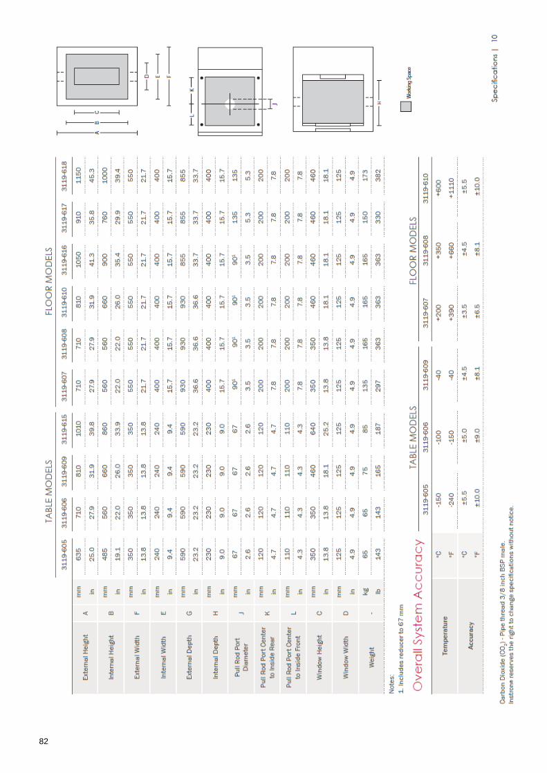
Thermal chamber for adhesives creep testing machine
82

Thermal chamber for adhesives creep testing machine
83

Thermal chamber for adhesives creep testing machine
84

Thermal chamber for adhesives creep testing machine
85
Appendix B: Technical drawings

2020012701A A
B B
C C
D D
E E
F F
8
8
7
7
6
6
5
5
4
4
3
3
2
2
1
1
DRAWN
CHK'D
APPV'D
MFG
Q.AA3
SHEET 1 OF 1SCALE:1:20
Thermal chamber
DWG NO.
ANGULAR:
FINISH:
LINEAR:TOLERANCES:
EDGES
NAME SIGNATURE DATE
MATERIAL:
DO NOT SCALE DRAWING REVISION
TITLE:
UNLESS OTHERWISE SPECIFIED:DIMENSIONS ARE IN MILLIMETERSSURFACE FINISH:
DEBURR AND BREAK SHARP
WEIGHT:
675
336
494
607
798
3
9.25
50
414
SOLIDWORKS Educational Product. For Instructional Use Only.
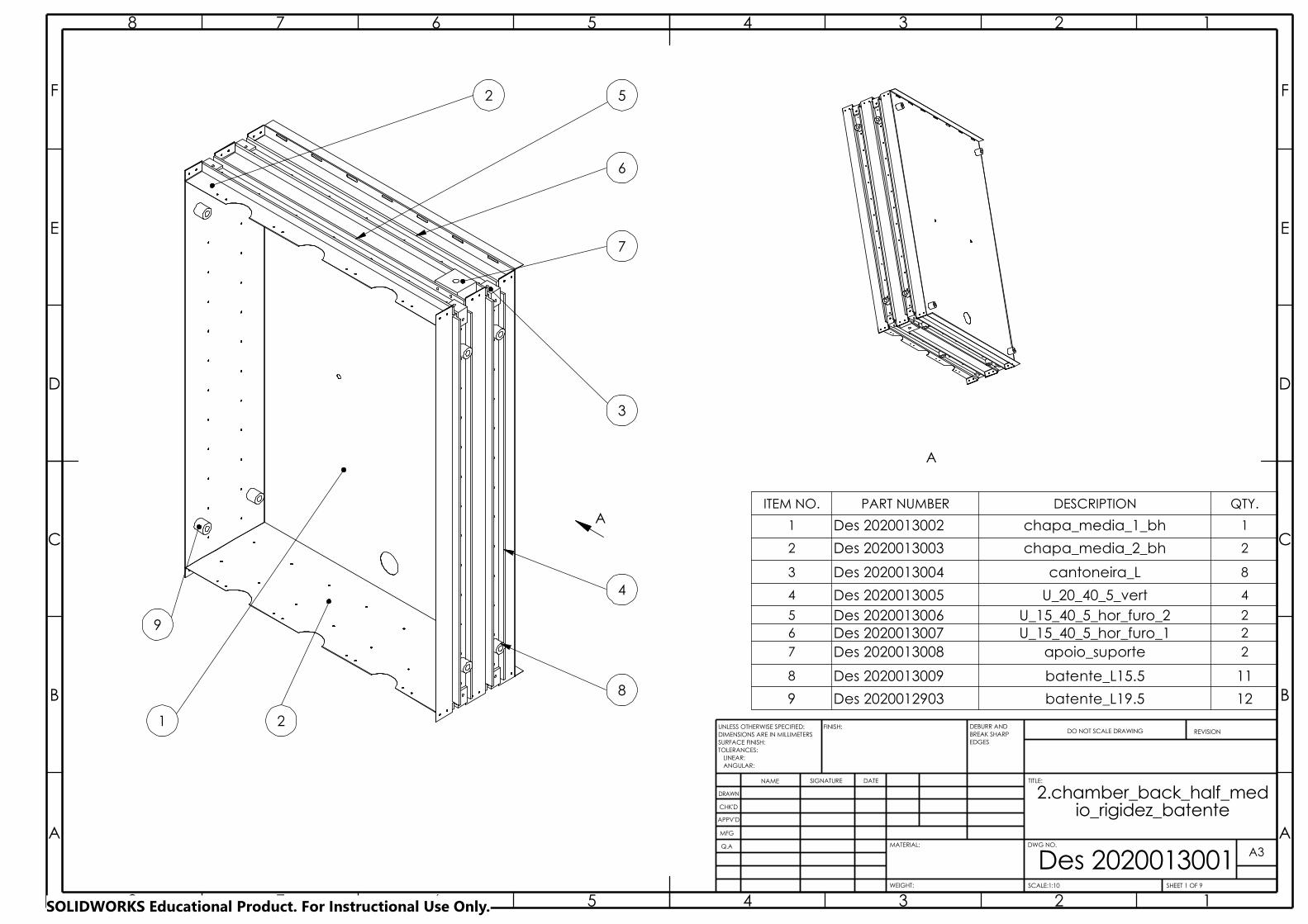
BREAK SHARP
A A
B B
C C
D D
E E
F F
8
8
7
7
6
6
5
5
4
4
3
3
2
2
1
1
DRAWN
CHK'D
APPV'D
MFG
Q.A
Des 2020013001WEIGHT:
A3
SHEET 1 OF 9SCALE:1:10
ANGULAR:
FINISH:
LINEAR:TOLERANCES:
EDGES
NAME SIGNATURE DATE
MATERIAL:
DO NOT SCALE DRAWING REVISION
TITLE:
DWG NO.
UNLESS OTHERWISE SPECIFIED:DIMENSIONS ARE IN MILLIMETERSSURFACE FINISH:
DEBURR AND
2.chamber_back_half_medio_rigidez_batente
21
2
3
4
8
6
7
5
9
AITEM NO. PART NUMBER DESCRIPTION QTY.
1 Des 2020013002 chapa_media_1_bh 1
2 Des 2020013003 chapa_media_2_bh 2
3 Des 2020013004 cantoneira_L 8
4 Des 2020013005 U_20_40_5_vert 4
5 Des 2020013006 U_15_40_5_hor_furo_2 26 Des 2020013007 U_15_40_5_hor_furo_1 27 Des 2020013008 apoio_suporte 2
8 Des 2020013009 batente_L15.5 11
9 Des 2020012903 batente_L19.5 12
A
SOLIDWORKS Educational Product. For Instructional Use Only.
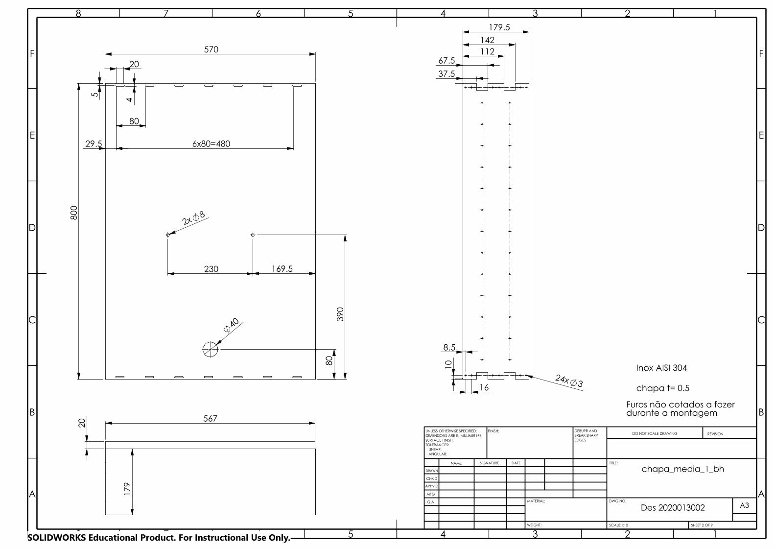
29.5
80
390
40
230
8
570
800
2x
4
80
6x80=480
20
5
169.5
567
20
179
3 24x
37.5
112 142
67.5
179.5
16
10
8.5
A3A A
B B
C C
D D
E E
F F
8
8
7
7
6
6
5
5
4
4
3
3
2
2
1
1
DRAWN
CHK'D
APPV'D
MFG
Q.A
WEIGHT: SHEET 2 OF 9
DWG NO.
Des 2020013002
SCALE:1:10
ANGULAR:
FINISH:
LINEAR:TOLERANCES:
EDGES
NAME SIGNATURE DATE
MATERIAL:
DO NOT SCALE DRAWING REVISION
TITLE:
UNLESS OTHERWISE SPECIFIED:DIMENSIONS ARE IN MILLIMETERSSURFACE FINISH:
DEBURR AND BREAK SHARP
chapa_media_1_bh
chapa t= 0.5
Inox AISI 304
Furos não cotados a fazerdurante a montagem
SOLIDWORKS Educational Product. For Instructional Use Only.
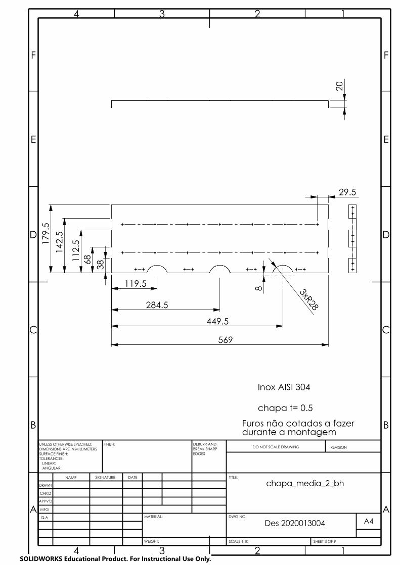
20
112
.5
179
.5
119.5
284.5
8
449.5
38
569
3xR28 6
8 142
.5
29.5
chapa t= 0.5
Inox AISI 304
Furos não cotados a fazerdurante a montagem
SHEET 3 OF 9
Des 2020013004
A A
B B
C C
D D
E E
F F
4
4
3
3
2
2
1
1
DRAWN
CHK'D
APPV'D
MFG
A4
TITLE:
WEIGHT: SCALE:1:10
DWG NO.Q.A
ANGULAR: LINEAR:
FINISH:
TOLERANCES:EDGES
NAME SIGNATURE DATE
MATERIAL:
DO NOT SCALE DRAWING REVISIONUNLESS OTHERWISE SPECIFIED:DIMENSIONS ARE IN MILLIMETERSSURFACE FINISH:
DEBURR AND BREAK SHARP
chapa_media_2_bh
SOLIDWORKS Educational Product. For Instructional Use Only.

Teflon26 peças
A4A A
B B
C C
D D
E E
F F
4
4
3
3
2
2
1
1
DRAWN
CHK'D
APPV'D
MFG
Q.A
WEIGHT: SCALE:2:1
DWG NO.
SHEET 4 OF 9
Des 2020013009
ANGULAR:
FINISH:
LINEAR:TOLERANCES:
EDGES
NAME SIGNATURE DATE
MATERIAL:
DO NOT SCALE DRAWING REVISION
TITLE:
UNLESS OTHERWISE SPECIFIED:DIMENSIONS ARE IN MILLIMETERSSURFACE FINISH:
DEBURR AND BREAK SHARP
batente_L15.5
15.
5
20
SOLIDWORKS Educational Product. For Instructional Use Only.

Des 2020013004A A
B B
C C
D D
E E
F F
4
4
3
3
2
2
1
1
DRAWN
CHK'D
APPV'D
MFG
Q.A
WEIGHT:
DWG NO.
SCALE:2:1
A4
SHEET 5 OF 9
ANGULAR:
FINISH:
LINEAR:TOLERANCES:
EDGES
NAME SIGNATURE DATE
MATERIAL:
DO NOT SCALE DRAWING REVISION
TITLE:
UNLESS OTHERWISE SPECIFIED:DIMENSIONS ARE IN MILLIMETERSSURFACE FINISH:
DEBURR AND BREAK SHARP
cantoneira_L
DIN 17100
Perfil L 30x30x4
14
4
19
2xM5
19
SOLIDWORKS Educational Product. For Instructional Use Only.

A4A A
B B
C C
D D
E E
F F
4
4
3
3
2
2
1
1
DRAWN
CHK'D
APPV'D
MFG
Q.A
WEIGHT: SHEET 6 OF 9SCALE:1:5
DWG NO.
Des 2020013007
ANGULAR:
FINISH:
LINEAR:TOLERANCES:
EDGES
NAME SIGNATURE DATE
MATERIAL:
DO NOT SCALE DRAWING REVISION
TITLE:
UNLESS OTHERWISE SPECIFIED:DIMENSIONS ARE IN MILLIMETERSSURFACE FINISH:
DEBURR AND BREAK SHARP
U_15_40_5_hor_furo_1
Perfil U 30x15x4
DIN 17100
3 7x
10
2xM5
548
85
15
6x8
5=51
0 2
9
29
2xM5
(56
8)
30
10
SOLIDWORKS Educational Product. For Instructional Use Only.
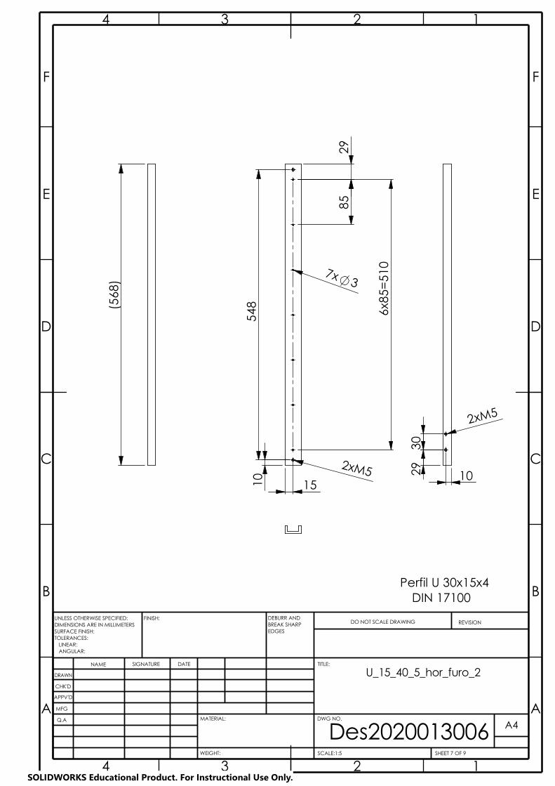
A4A A
B B
C C
D D
E E
F F
4
4
3
3
2
2
1
1
DRAWN
CHK'D
APPV'D
MFG
Q.A
WEIGHT: SHEET 7 OF 9
DWG NO.
Des2020013006SCALE:1:5
ANGULAR:
FINISH:
LINEAR:TOLERANCES:
EDGES
NAME SIGNATURE DATE
MATERIAL:
DO NOT SCALE DRAWING REVISION
TITLE:
UNLESS OTHERWISE SPECIFIED:DIMENSIONS ARE IN MILLIMETERSSURFACE FINISH:
DEBURR AND BREAK SHARP
U_15_40_5_hor_furo_2
15
7x 3
10
2xM5
548
85
6x8
5=51
0
29
Perfil U 30x15x4DIN 17100
(56
8)
30
29
10
2xM5
SOLIDWORKS Educational Product. For Instructional Use Only.

A4A A
B B
C C
D D
E E
F F
4
4
3
3
2
2
1
1
DRAWN
CHK'D
APPV'D
MFG
Q.A
WEIGHT: SHEET 8 OF 9SCALE:1:5
DWG NO.
Des 2020013005
ANGULAR:
FINISH:
LINEAR:TOLERANCES:
EDGES
NAME SIGNATURE DATE
MATERIAL:
DO NOT SCALE DRAWING REVISION
TITLE:
UNLESS OTHERWISE SPECIFIED:DIMENSIONS ARE IN MILLIMETERSSURFACE FINISH:
DEBURR AND BREAK SHARP
U_20_40_5_vert
(75
8)
9.5
7
39
15
5
2x
58
12x
58=
696
31
13x 3
Perfil U 30x15x4
DIN 17100
SOLIDWORKS Educational Product. For Instructional Use Only.
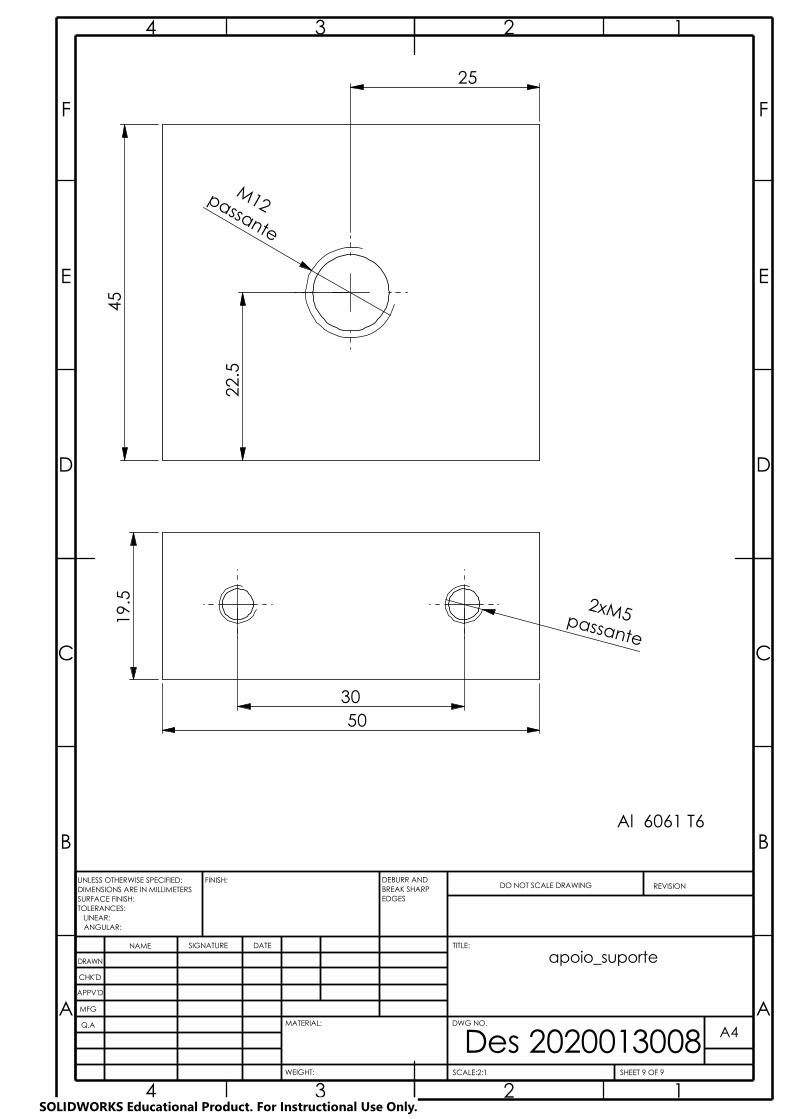
30 50
2xM5passante
19.
5
M12
45
passante
25
22.
5
Al 6061 T6
SHEET 9 OF 9
Des 2020013008SCALE:2:1WEIGHT:
A4A A
B B
C C
D D
E E
F F
4
4
3
3
2
2
1
1
DRAWN
REVISIONDO NOT SCALE DRAWING
TITLE:
DWG NO.MATERIAL:
CHK'D
APPV'D
LINEAR:
MFG
Q.A
ANGULAR:
FINISH:
TOLERANCES:EDGES
NAME SIGNATURE DATE
UNLESS OTHERWISE SPECIFIED:DIMENSIONS ARE IN MILLIMETERSSURFACE FINISH:
DEBURR AND BREAK SHARP
apoio_suporte
SOLIDWORKS Educational Product. For Instructional Use Only.
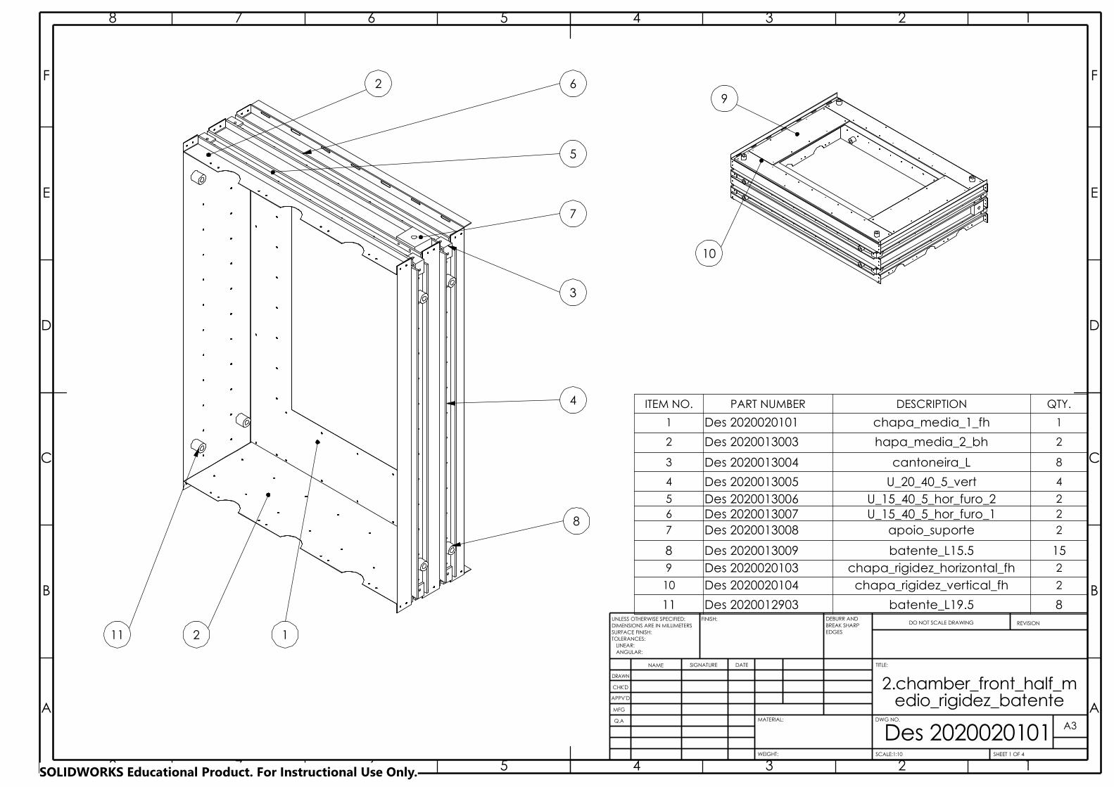
2
4
3
2
8
5
1
6
7
11
9
10
ITEM NO. PART NUMBER DESCRIPTION QTY.
1 Des 2020020101 chapa_media_1_fh 1
2 Des 2020013003 hapa_media_2_bh 2
3 Des 2020013004 cantoneira_L 8
4 Des 2020013005 U_20_40_5_vert 4
5 Des 2020013006 U_15_40_5_hor_furo_2 26 Des 2020013007 U_15_40_5_hor_furo_1 27 Des 2020013008 apoio_suporte 2
8 Des 2020013009 batente_L15.5 159 Des 2020020103 chapa_rigidez_horizontal_fh 2
10 Des 2020020104 chapa_rigidez_vertical_fh 2
11 Des 2020012903 batente_L19.5 8
3
3
2
2
1
DRAWN
4
4
5
5
6
CHK'D
APPV'D
SHEET 1 OF 4
MFG
Q.A
ANGULAR:
FINISH:
TOLERANCES:EDGES
NAME SIGNATURE DATE
MATERIAL:
DO NOT SCALE DRAWING REVISION
TITLE:
DWG NO.
SCALE:1:10
A3
WEIGHT:
Des 2020020101
LINEAR:
BREAK SHARP
edio_rigidez_batenteA A
B B
C C
D D
E E
F F
8
8
7
7
6
UNLESS OTHERWISE SPECIFIED:DIMENSIONS ARE IN MILLIMETERSSURFACE FINISH:
DEBURR AND
2.chamber_front_half_m
1
SOLIDWORKS Educational Product. For Instructional Use Only.

800
5
500
4
20
570
80
6x80=480
350
29.5
16
24x 3
37.5 67.5
142 112
179.5
8.5
10
567
20
179
Des 2020020101A A
B B
C C
D D
E E
F F
8
8
7
7
6
6
5
5
4
4
3
3
2
2
1
1
DRAWN
CHK'D
APPV'D
MFG
Q.A
WEIGHT:
A3
SHEET 2 OF 4SCALE:1:10
DWG NO.
ANGULAR:
FINISH:
LINEAR:TOLERANCES:
EDGES
NAME SIGNATURE DATE
MATERIAL:
DO NOT SCALE DRAWING REVISION
TITLE:
UNLESS OTHERWISE SPECIFIED:DIMENSIONS ARE IN MILLIMETERSSURFACE FINISH:
DEBURR AND BREAK SHARP
chapa_media_1_fh
Inox AISI 304
durante a montagemFuros não cotados a fazer
chapa t= 0.5
SOLIDWORKS Educational Product. For Instructional Use Only.
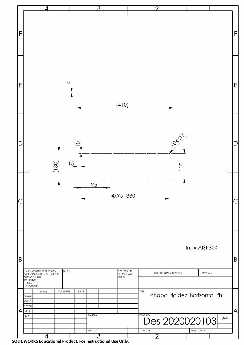
10
(13
0)
15
95
4x95=380
110
10x
3
4
(410)
Inox AISI 304
Des 2020020103A A
B B
C C
D D
E E
F F
4
4
3
3
2
2
1
1
DRAWN
CHK'D
APPV'D
MFG
Q.A
WEIGHT:
A4
SHEET 3 OF 4SCALE:1:5
DWG NO.
ANGULAR:
FINISH:
LINEAR:TOLERANCES:
EDGES
NAME SIGNATURE DATE
MATERIAL:
DO NOT SCALE DRAWING REVISION
TITLE:
UNLESS OTHERWISE SPECIFIED:DIMENSIONS ARE IN MILLIMETERSSURFACE FINISH:
DEBURR AND BREAK SHARP
chapa_rigidez_horizontal_fh
SOLIDWORKS Educational Product. For Instructional Use Only.
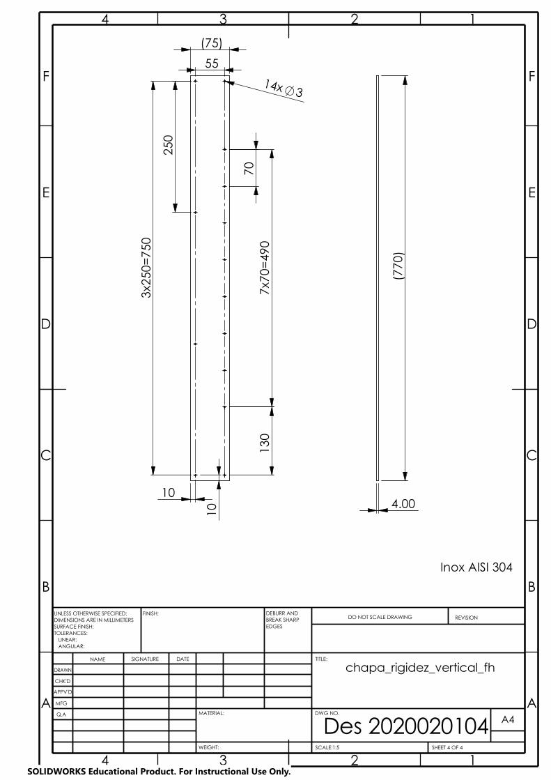
Inox AISI 304
55
10
3
250
(75)
3x2
50=
750
14x
70
7x7
0=49
0 1
30
10
Des 2020020104A A
B B
C C
D D
E E
F F
4
4
3
3
2
2
1
1
DRAWN
CHK'D
APPV'D
MFG
Q.A
WEIGHT:
A4
SHEET 4 OF 4SCALE:1:5
DWG NO.
ANGULAR:
FINISH:
LINEAR:TOLERANCES:
EDGES
NAME SIGNATURE DATE
MATERIAL:
DO NOT SCALE DRAWING REVISION
TITLE:
UNLESS OTHERWISE SPECIFIED:DIMENSIONS ARE IN MILLIMETERSSURFACE FINISH:
DEBURR AND BREAK SHARP
chapa_rigidez_vertical_fh
(77
0)
4.00
SOLIDWORKS Educational Product. For Instructional Use Only.
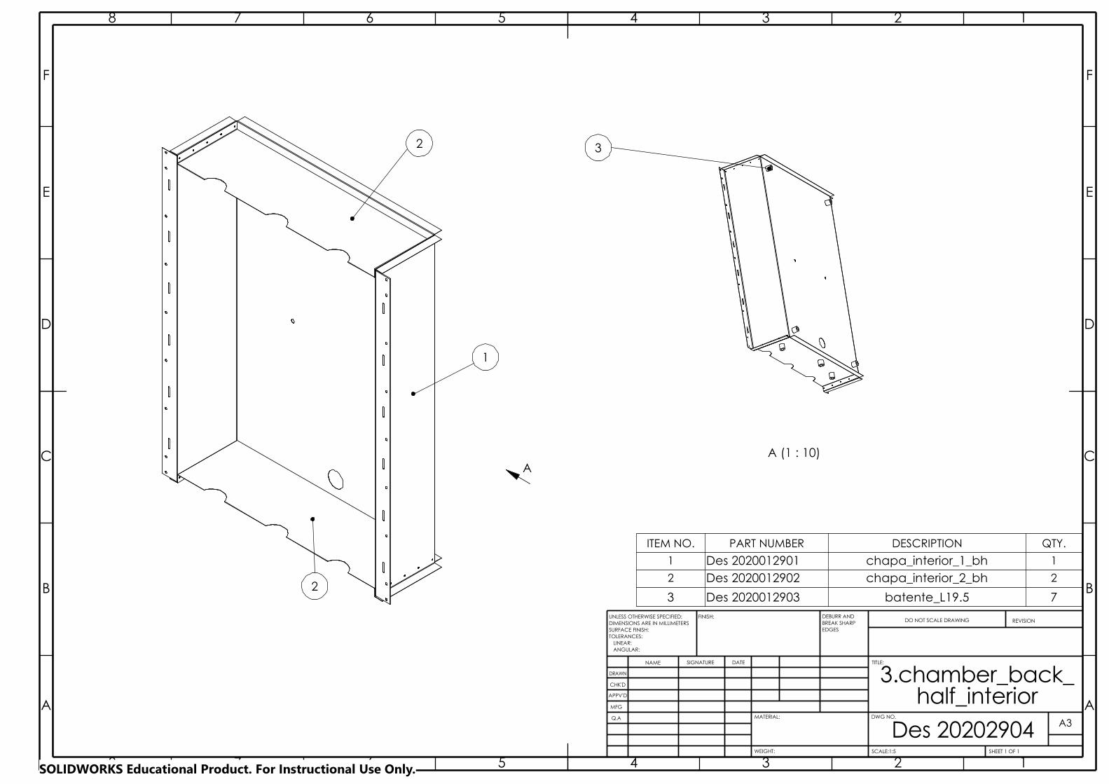
2
1
DRAWN
CHK'D
APPV'D
MFG
2
3
3
4
4
Q.A
ANGULAR:
Des 20202904
FINISH:
TOLERANCES:EDGES
NAME SIGNATURE DATE
MATERIAL:
DO NOT SCALE DRAWING REVISION
TITLE:
DWG NO.
SCALE:1:5 SHEET 1 OF 1
A3
WEIGHT:
LINEAR:
BREAK SHARP
half_interiorA A
B B
C C
D D
E E
F F
8
8
7
7
6
6
5
5
UNLESS OTHERWISE SPECIFIED:DIMENSIONS ARE IN MILLIMETERSSURFACE FINISH:
DEBURR AND
3.chamber_back_
1
1
2
2
AA (1 : 10)
3
ITEM NO. PART NUMBER DESCRIPTION QTY.
1 Des 2020012901 chapa_interior_1_bh 1
2 Des 2020012902 chapa_interior_2_bh 2
3 Des 2020012903 batente_L19.5 7
SOLIDWORKS Educational Product. For Instructional Use Only.
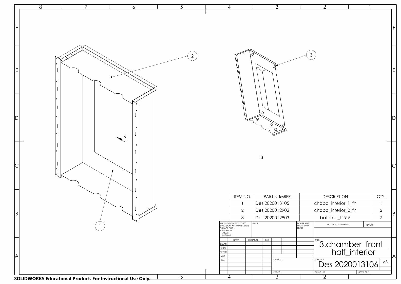
LINEAR:
BREAK SHARP
A A
B B
C C
D D
E E
F F
8
8
7
7
6
6
5
5
4
4
3
3
2
2
1
1
DRAWN
CHK'D
APPV'D
MFG
WEIGHT:
A3
SHEET 1 OF 2SCALE:1:10
DWG NO.Q.A
ANGULAR:
Des 2020013106
FINISH:
TOLERANCES:EDGES
NAME SIGNATURE DATE
MATERIAL:
DO NOT SCALE DRAWING REVISION
TITLE:
UNLESS OTHERWISE SPECIFIED:DIMENSIONS ARE IN MILLIMETERSSURFACE FINISH:
DEBURR AND
3.chamber_front_half_interior
1
2
B
ITEM NO. PART NUMBER DESCRIPTION QTY.
1 Des 2020013105 chapa_interior_1_fh 1
2 Des 2020012902 chapa_interior_2_fh 2
3 Des 2020012903 batente_L19.5 7
B
3
SOLIDWORKS Educational Product. For Instructional Use Only.
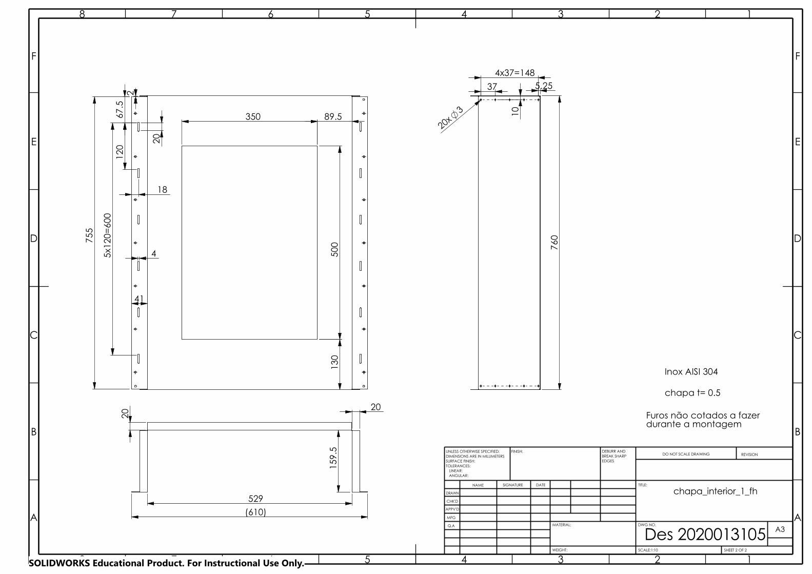
Des 2020013105A A
B B
C C
D D
E E
F F
8
8
7
7
6
6
5
5
4
4
3
3
2
2
1
1
DRAWN
CHK'D
APPV'D
MFG
Q.A
WEIGHT:
A3
SHEET 2 OF 2SCALE:1:10
DWG NO.
ANGULAR:
FINISH:
LINEAR:TOLERANCES:
EDGES
NAME SIGNATURE DATE
MATERIAL:
DO NOT SCALE DRAWING REVISION
TITLE:
UNLESS OTHERWISE SPECIFIED:DIMENSIONS ARE IN MILLIMETERSSURFACE FINISH:
DEBURR AND BREAK SHARP
chapa_interior_1_fh
500
755
2
120
6
7.5
41
5x1
20=
600
4
350
18
20
89.5
130
chapa t= 0.5
Inox AISI 304
Furos não cotados a fazerdurante a montagem
20
(610)
529
159
.5
20
760
5.25
3
20x
37
4x37=148
10
SOLIDWORKS Educational Product. For Instructional Use Only.
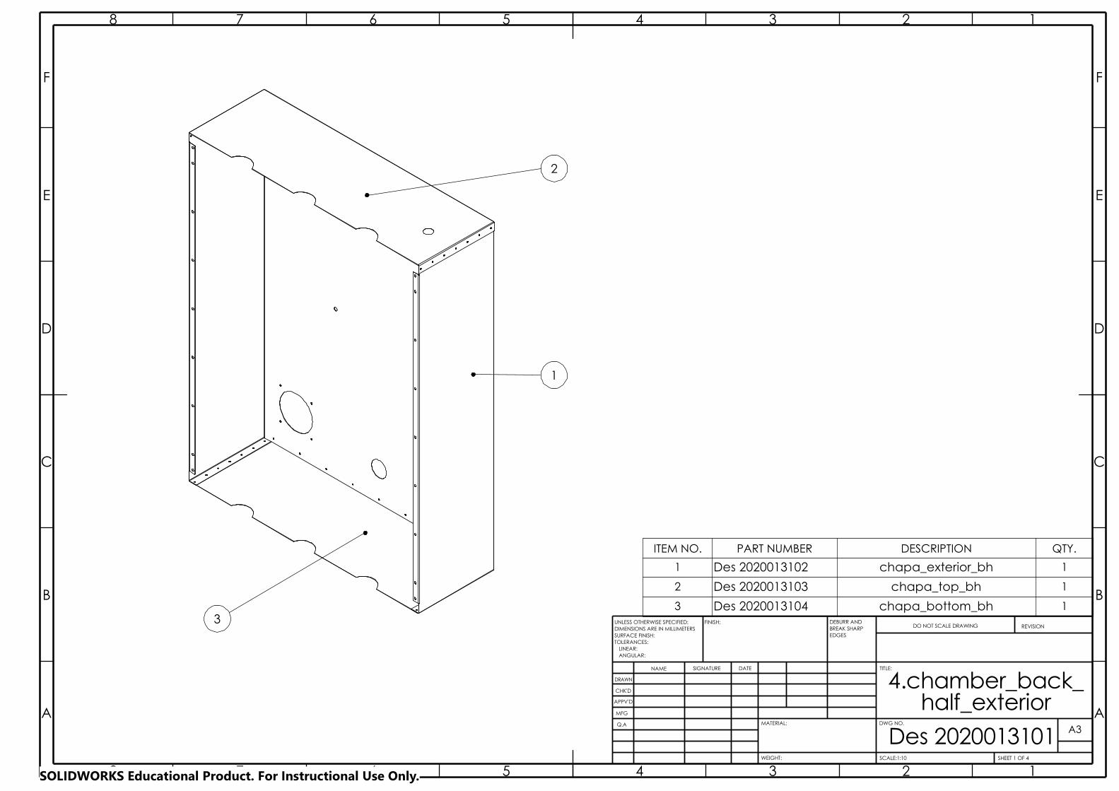
LINEAR:
BREAK SHARP
A A
B B
C C
D D
E E
F F
8
8
7
7
6
6
5
5
4
4
3
3
2
2
1
1
DRAWN
CHK'D
APPV'D
MFG
WEIGHT:
A3
SHEET 1 OF 4SCALE:1:10
DWG NO.Q.A
ANGULAR:
Des 2020013101
FINISH:
TOLERANCES:EDGES
NAME SIGNATURE DATE
MATERIAL:
DO NOT SCALE DRAWING REVISION
TITLE:
UNLESS OTHERWISE SPECIFIED:DIMENSIONS ARE IN MILLIMETERSSURFACE FINISH:
DEBURR AND
4.chamber_back_half_exterior
1
2
3
ITEM NO. PART NUMBER DESCRIPTION QTY.
1 Des 2020013102 chapa_exterior_bh 1
2 Des 2020013103 chapa_top_bh 1
3 Des 2020013104 chapa_bottom_bh 1
SOLIDWORKS Educational Product. For Instructional Use Only.
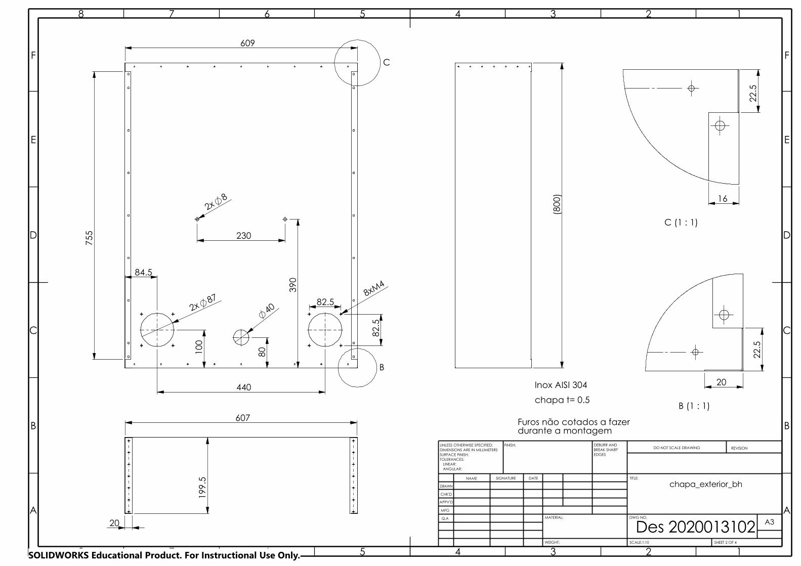
Des 2020013102A A
B B
C C
D D
E E
F F
8
8
7
7
6
6
5
5
4
4
3
3
2
2
1
1
DRAWN
CHK'D
APPV'D
MFG
Q.A
WEIGHT:
A3
SHEET 2 OF 4SCALE:1:10
DWG NO.
ANGULAR:
FINISH:
LINEAR:TOLERANCES:
EDGES
NAME SIGNATURE DATE
MATERIAL:
DO NOT SCALE DRAWING REVISION
TITLE:
UNLESS OTHERWISE SPECIFIED:DIMENSIONS ARE IN MILLIMETERSSURFACE FINISH:
DEBURR AND BREAK SHARP
chapa_exterior_bh
C (1 : 1)
16
22.
5
(80
0)
B (1 : 1)
22.
5
20
chapa t= 0.5
Inox AISI 304
Furos não cotados a fazerdurante a montagem
B
C
609
87 2x 40
8
80
230
390
84.5
100
440
8xM4
82.
5
82.5
2x
755
607
199
.5
20
SOLIDWORKS Educational Product. For Instructional Use Only.

Des 2020013103A A
B B
C C
D D
E E
F F
4
4
3
3
2
2
1
1
DRAWN
CHK'D
APPV'D
MFG
Q.A
WEIGHT:
A4
SHEET 3 OF 4SCALE:1:10
DWG NO.
ANGULAR:
FINISH:
LINEAR:TOLERANCES:
EDGES
NAME SIGNATURE DATE
MATERIAL:
DO NOT SCALE DRAWING REVISION
TITLE:
UNLESS OTHERWISE SPECIFIED:DIMENSIONS ARE IN MILLIMETERSSURFACE FINISH:
DEBURR AND BREAK SHARP
chapa_top_bh
chapa t= 0.5
Inox AISI 304
470.5
200
.5
3xR28
8
20
140.5
305.5 9
0
611
70 8x70=560
9.5
3
9x 25.5
20 3
14x
31
186
5
9.5
SOLIDWORKS Educational Product. For Instructional Use Only.
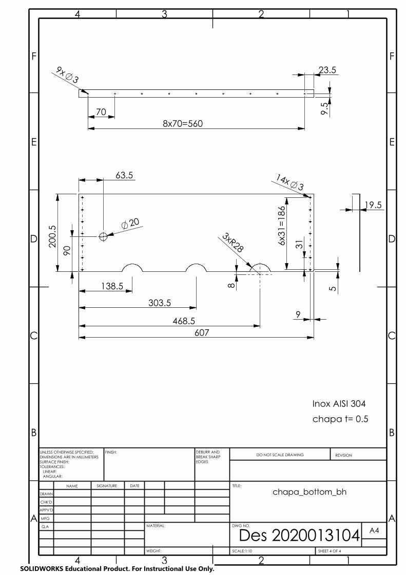
WEIGHT:
Des 2020013104A A
B B
C C
D D
E E
F F
4
4
3
3
2
2
1
1
DRAWN
CHK'D
APPV'D
MFG
A4
SHEET 4 OF 4SCALE:1:10
DWG NO.
TITLE:
Q.A
ANGULAR: LINEAR:
FINISH:
TOLERANCES:EDGES
NAME SIGNATURE DATE
MATERIAL:
DO NOT SCALE DRAWING REVISIONUNLESS OTHERWISE SPECIFIED:DIMENSIONS ARE IN MILLIMETERSSURFACE FINISH:
DEBURR AND BREAK SHARP
chapa_bottom_bh
Inox AISI 304
chapa t= 0.5
20
138.5
303.5
468.5
63.5
607
31
90 2
00.5
9
14x3
6x3
1=18
6
5 8
3xR28
19.5
9x
8x70=560
3
9.5
70
23.5
SOLIDWORKS Educational Product. For Instructional Use Only.
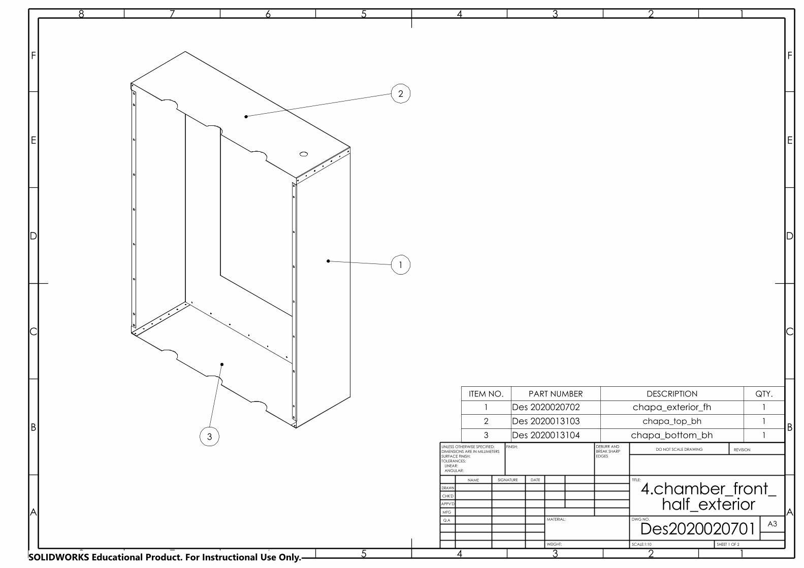
ITEM NO. PART NUMBER DESCRIPTION QTY.
1 Des 2020020702 chapa_exterior_fh 1
2 Des 2020013103 chapa_top_bh 1
3 Des 2020013104 chapa_bottom_bh 1
BREAK SHARP
A A
B B
C C
D D
E E
F F
8
8
7
7
6
6
5
5
4
4
3
3
2
2
1
1
DRAWN
CHK'D
APPV'D
MFG
Q.A
Des2020020701WEIGHT: SCALE:1:10
DWG NO.
SHEET 1 OF 2
ANGULAR:
FINISH:
LINEAR:TOLERANCES:
EDGES
NAME SIGNATURE DATE
MATERIAL:
DO NOT SCALE DRAWING REVISION
TITLE:
A3
UNLESS OTHERWISE SPECIFIED:DIMENSIONS ARE IN MILLIMETERSSURFACE FINISH:
DEBURR AND
4.chamber_front_half_exterior
2
3
1
SOLIDWORKS Educational Product. For Instructional Use Only.
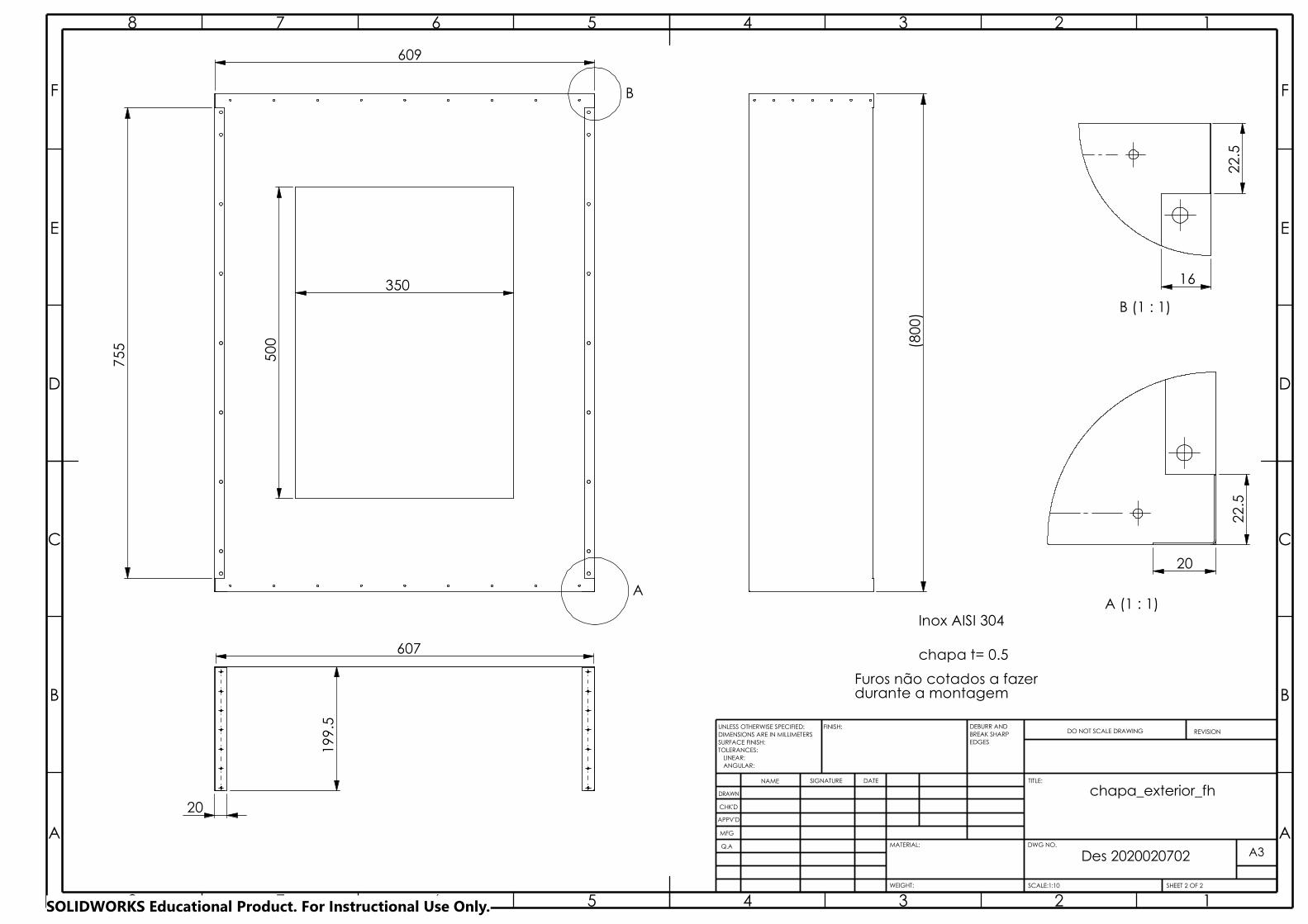
(80
0) B (1 : 1)
16
22.
5
Inox AISI 304
chapa t= 0.5
Furos não cotados a fazerdurante a montagem
A3A A
B B
C C
D D
E E
F F
8
8
7
7
6
6
5
5
4
4
3
3
2
2
1
1
DRAWN
CHK'D
APPV'D
MFG
Q.A
WEIGHT:
DWG NO.
Des 2020020702
SHEET 2 OF 2SCALE:1:10
ANGULAR:
FINISH:
LINEAR:TOLERANCES:
EDGES
NAME SIGNATURE DATE
MATERIAL:
DO NOT SCALE DRAWING REVISION
TITLE:
UNLESS OTHERWISE SPECIFIED:DIMENSIONS ARE IN MILLIMETERSSURFACE FINISH:
DEBURR AND BREAK SHARP
chapa_exterior_fh
A
B
500
609
350
755
607
199
.5
20
A (1 : 1)
20
22.
5
SOLIDWORKS Educational Product. For Instructional Use Only.

Des 2020012903
A A
B B
C C
D D
E E
F F
4
4
3
3
2
2
1
1
DRAWN
CHK'D
APPV'D
MFG
Q.AA4
SHEET 1 OF 1SCALE:5:1WEIGHT:
DWG NO.
ANGULAR:
FINISH:
LINEAR:TOLERANCES:
EDGES
NAME SIGNATURE DATE
MATERIAL:
DO NOT SCALE DRAWING REVISION
TITLE:
UNLESS OTHERWISE SPECIFIED:DIMENSIONS ARE IN MILLIMETERSSURFACE FINISH:
DEBURR AND BREAK SHARP
batente_L19.5
20
19.
5
Teflon 34 peças
SOLIDWORKS Educational Product. For Instructional Use Only.

BREAK SHARP
DRAWN
CHK'D
APPV'D
MFG
Q.A
Des 2020012901
2
3
3
4
ANGULAR:
FINISH:
LINEAR:TOLERANCES:
EDGES
NAME SIGNATURE DATE
MATERIAL:
DO NOT SCALE DRAWING REVISION
TITLE:
A3DWG NO.
SCALE:1:5
1WEIGHT: SHEET 1 OF 1
2
bhA A
B B
C C
D D
E E
F F
8
8
7
7
6
6
5
5
4
UNLESS OTHERWISE SPECIFIED:DIMENSIONS ARE IN MILLIMETERSSURFACE FINISH:
DEBURR AND
chapa_interior_1_
1
Inox AISI 304
chapa t= 0.5
Furos não cotados a fazerdurante a montagem
67.
5 1
20
5x1
20=
600
8 2x
20
755
40.5
4
60
370
18
230
2
40
159
.5
(610)
20
20
529
37
760
5.25
4x37=148
10
20x
3
SOLIDWORKS Educational Product. For Instructional Use Only.

BREAK SHARP
A A
B B
C C
D D
E E
F F
4
4
3
3
2
2
1
1
DRAWN
CHK'D
APPV'D
MFG
Q.A
Des 2020012902
WEIGHT:
A4
SHEET 1 OF 1SCALE:1:5
ANGULAR:
FINISH:
LINEAR:TOLERANCES:
EDGES
NAME SIGNATURE DATE
MATERIAL:
DO NOT SCALE DRAWING REVISION
TITLE:
DWG NO.
UNLESS OTHERWISE SPECIFIED:DIMENSIONS ARE IN MILLIMETERSSURFACE FINISH:
DEBURR AND
chapa_interior_2_bh
429.5
3xR28
529
159
.5
264.5
99.5 8
chapa t= 0.5
Inox AISI 304
Furos não cotados a fazerdurante a montagem
20
SOLIDWORKS Educational Product. For Instructional Use Only.
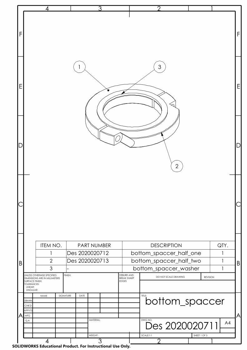
Des 2020020711A A
B B
C C
D D
E E
F F
4
4
3
3
2
2
1
1
DRAWN
CHK'D
APPV'D
MFG
Q.A
WEIGHT:
A4
SHEET 1 OF 3SCALE:1:1
DWG NO.
ANGULAR:
FINISH:
LINEAR:TOLERANCES:
EDGES
NAME SIGNATURE DATE
MATERIAL:
DO NOT SCALE DRAWING REVISION
TITLE:
UNLESS OTHERWISE SPECIFIED:DIMENSIONS ARE IN MILLIMETERSSURFACE FINISH:
DEBURR AND BREAK SHARP
bottom_spaccer
31
2
ITEM NO. PART NUMBER DESCRIPTION QTY.
1 Des 2020020712 bottom_spaccer_half_one 1
2 Des 2020020713 bottom_spaccer_half_two 1
3 - bottom_spaccer_washer 1
SOLIDWORKS Educational Product. For Instructional Use Only.
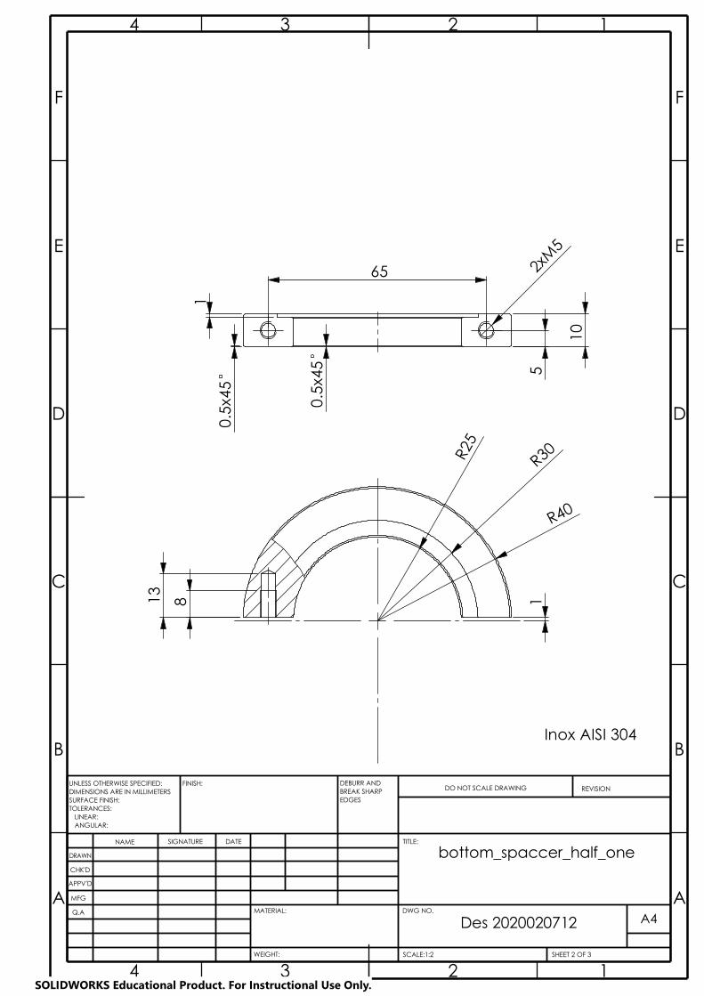
Des 2020020712
A A
B B
C C
D D
E E
F F
4
4
3
3
2
2
1
1
DRAWN
CHK'D
APPV'D
MFG
Q.A
WEIGHT:
A4
SHEET 2 OF 3SCALE:1:2
DWG NO.
ANGULAR:
FINISH:
LINEAR:TOLERANCES:
EDGES
NAME SIGNATURE DATE
MATERIAL:
DO NOT SCALE DRAWING REVISION
TITLE:
UNLESS OTHERWISE SPECIFIED:DIMENSIONS ARE IN MILLIMETERSSURFACE FINISH:
DEBURR AND BREAK SHARP
bottom_spaccer_half_one
Inox AISI 304
R25
R40
8
R30
13
1
1
2xM
5
10
5
0.5
x45
0.5
x45
65
SOLIDWORKS Educational Product. For Instructional Use Only.
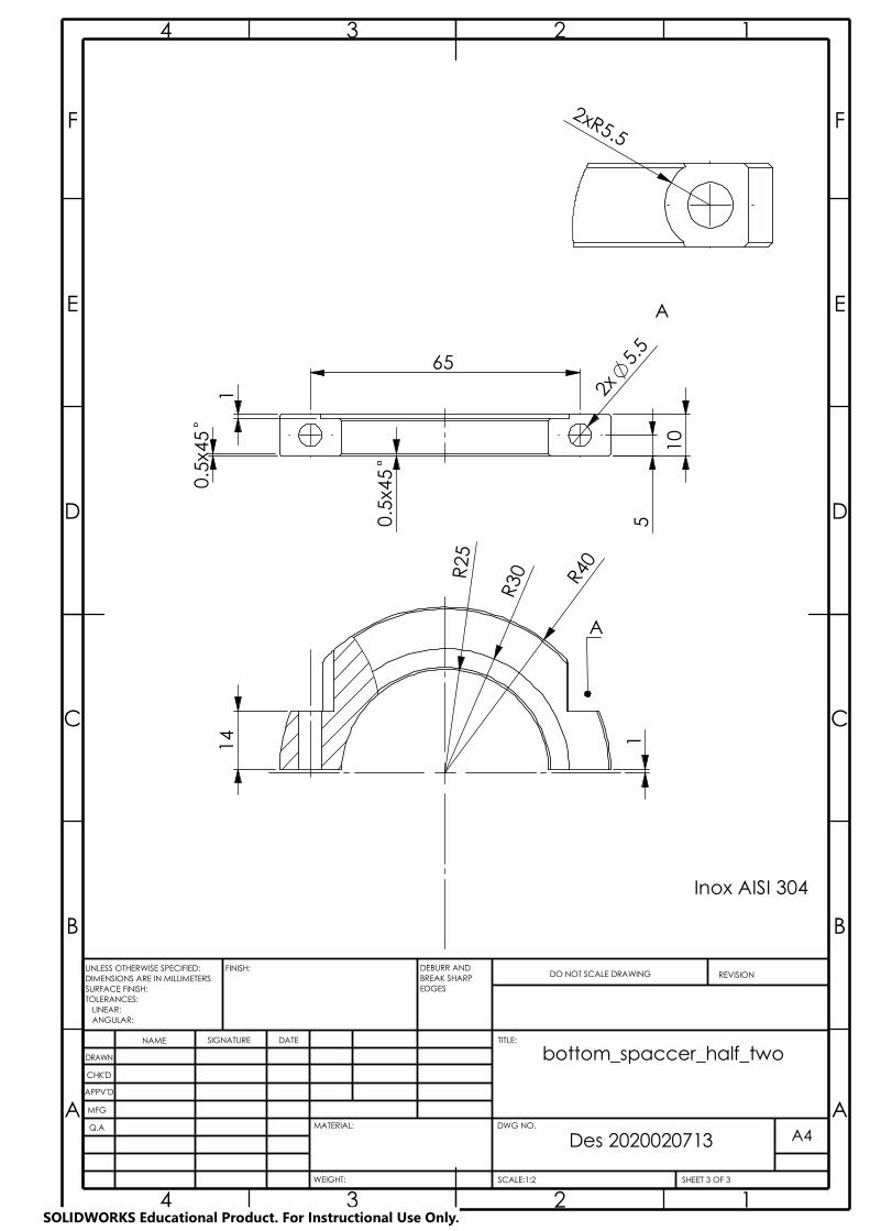
Des 2020020713
A A
B B
C C
D D
E E
F F
4
4
3
3
2
2
1
1
DRAWN
CHK'D
APPV'D
MFG
Q.A
WEIGHT:
A4
SHEET 3 OF 3SCALE:1:2
DWG NO.
ANGULAR:
FINISH:
LINEAR:TOLERANCES:
EDGES
NAME SIGNATURE DATE
MATERIAL:
DO NOT SCALE DRAWING REVISION
TITLE:
UNLESS OTHERWISE SPECIFIED:DIMENSIONS ARE IN MILLIMETERSSURFACE FINISH:
DEBURR AND BREAK SHARP
bottom_spaccer_half_two
65
1
10
5
0
.5x4
5
0.5
x45
2x
5.5
A
A
Inox AISI 304
R25
R30
14
R40
1
2xR5.5
SOLIDWORKS Educational Product. For Instructional Use Only.
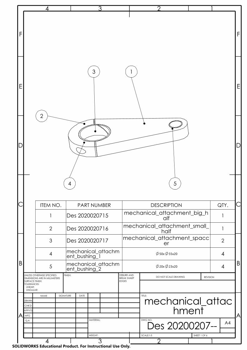
BREAK SHARP
A A
B B
C C
D D
E E
F F
4
4
3
3
2
2
1
1
DRAWN
CHK'D
APPV'D
MFG
Q.A
Des 20200207--WEIGHT:
A4
SHEET 1 OF 6SCALE:1:5
ANGULAR:
FINISH:
LINEAR:TOLERANCES:
EDGES
NAME SIGNATURE DATE
MATERIAL:
DO NOT SCALE DRAWING REVISION
TITLE:
DWG NO.
UNLESS OTHERWISE SPECIFIED:DIMENSIONS ARE IN MILLIMETERSSURFACE FINISH:
DEBURR AND
mechanical_attachment
3 1
5
2
4
ITEM NO. PART NUMBER DESCRIPTION QTY.
1 Des 2020020715 mechanical_attachment_big_half 1
2 Des 2020020716 mechanical_attachment_small_half 1
3 Des 2020020717 mechanical_attachment_spaccer 2
4 mechanical_attachment_bushing_1
50x 55x20 4
5 mechanical_attachment_bushing_2
20x 23x20 4
SOLIDWORKS Educational Product. For Instructional Use Only.
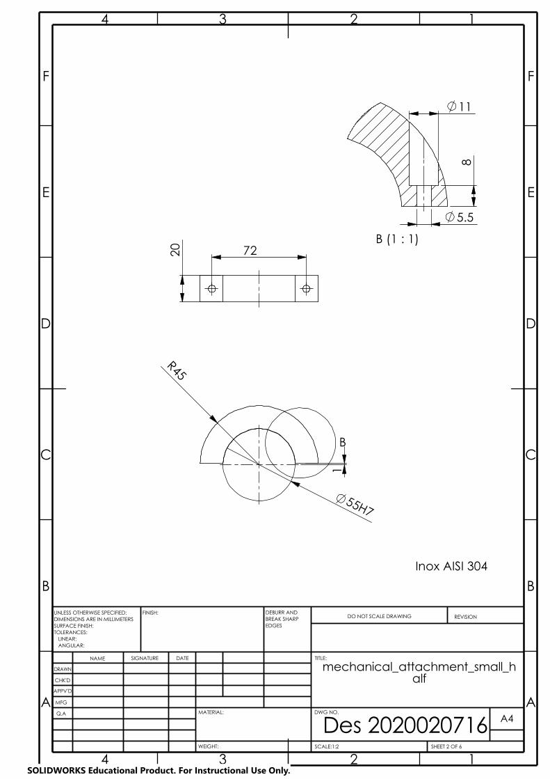
55H7
BREAK SHARP
A A
B B
C C
D D
E E
F F
4
4
3
3
2
2
1
1
DRAWN
CHK'D
APPV'D
MFG
Q.A
Des 2020020716WEIGHT:
A4
SHEET 2 OF 6SCALE:1:2
ANGULAR:
FINISH:
LINEAR:TOLERANCES:
EDGES
NAME SIGNATURE DATE
MATERIAL:
DO NOT SCALE DRAWING REVISION
TITLE:
DWG NO.
UNLESS OTHERWISE SPECIFIED:DIMENSIONS ARE IN MILLIMETERSSURFACE FINISH:
DEBURR AND
mechanical_attachment_small_half
Inox AISI 304
20 72
B
R45
1
B (1 : 1)
11
5.5
8
SOLIDWORKS Educational Product. For Instructional Use Only.
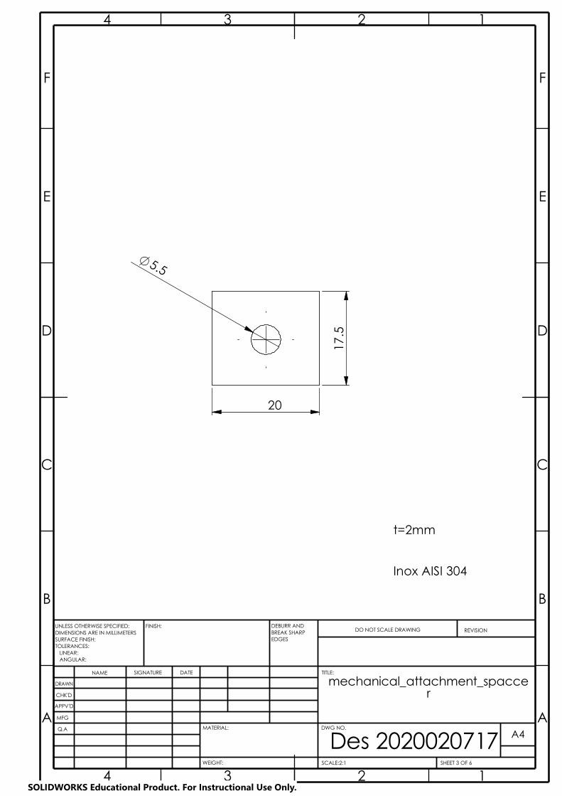
BREAK SHARP
A A
B B
C C
D D
E E
F F
4
4
3
3
2
2
1
1
DRAWN
CHK'D
APPV'D
MFG
Q.A
Des 2020020717WEIGHT:
A4
SHEET 3 OF 6SCALE:2:1
ANGULAR:
FINISH:
LINEAR:TOLERANCES:
EDGES
NAME SIGNATURE DATE
MATERIAL:
DO NOT SCALE DRAWING REVISION
TITLE:
DWG NO.
UNLESS OTHERWISE SPECIFIED:DIMENSIONS ARE IN MILLIMETERSSURFACE FINISH:
DEBURR AND
mechanical_attachment_spaccer
t=2mm
Inox AISI 304
17.
5
20
5.5
SOLIDWORKS Educational Product. For Instructional Use Only.

91
14
Inox AISI 304
BREAK SHARP
A A
B B
C C
D D
E E
F F
4
4
3
3
2
2
1
1
DRAWN
CHK'D
APPV'D
MFG
Q.A
Des 2020020715WEIGHT:
A4
SHEET 4 OF 6SCALE:1:5
ANGULAR:
FINISH:
LINEAR:TOLERANCES:
EDGES
NAME SIGNATURE DATE
MATERIAL:
DO NOT SCALE DRAWING REVISION
TITLE:
DWG NO.
UNLESS OTHERWISE SPECIFIED:DIMENSIONS ARE IN MILLIMETERSSURFACE FINISH:
DEBURR AND
mechanical_attachment_big_half
20
72
55H7
137
.4
R20
23
1
R45
A-A (1 : 1)
2xM5
9
SOLIDWORKS Educational Product. For Instructional Use Only.
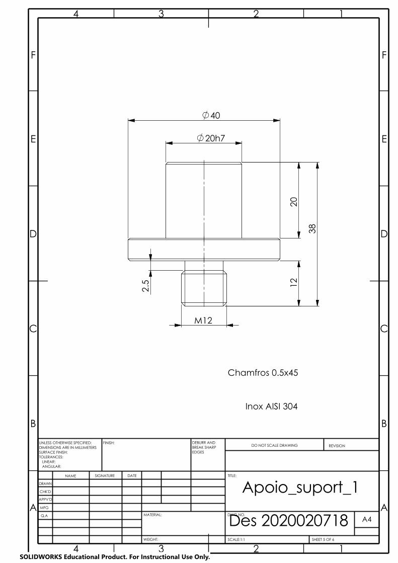
Des 2020020718A A
B B
C C
D D
E E
F F
4
4
3
3
2
2
1
1
DRAWN
CHK'D
APPV'D
MFG
Q.A
WEIGHT:
A4
SHEET 5 OF 6SCALE:1:1
DWG NO.
ANGULAR:
FINISH:
LINEAR:TOLERANCES:
EDGES
NAME SIGNATURE DATE
MATERIAL:
DO NOT SCALE DRAWING REVISION
TITLE:
UNLESS OTHERWISE SPECIFIED:DIMENSIONS ARE IN MILLIMETERSSURFACE FINISH:
DEBURR AND BREAK SHARP
Apoio_suport_1
Chamfros 0.5x45
Inox AISI 304
38
20h7
40
12
20
M12
2.5
SOLIDWORKS Educational Product. For Instructional Use Only.
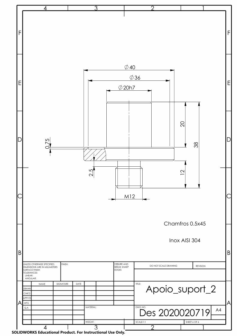
Des 2020020719A A
B B
C C
D D
E E
F F
4
4
3
3
2
2
1
1
DRAWN
CHK'D
APPV'D
MFG
Q.A
WEIGHT:
A4
SHEET 6 OF 6SCALE:1:1
DWG NO.
ANGULAR:
FINISH:
LINEAR:TOLERANCES:
EDGES
NAME SIGNATURE DATE
MATERIAL:
DO NOT SCALE DRAWING REVISION
TITLE:
UNLESS OTHERWISE SPECIFIED:DIMENSIONS ARE IN MILLIMETERSSURFACE FINISH:
DEBURR AND BREAK SHARP
Apoio_suport_2
Chamfros 0.5x45
Inox AISI 304
20h7
40
20
12
0.7
5
M12 3
8
2.5
36
SOLIDWORKS Educational Product. For Instructional Use Only.
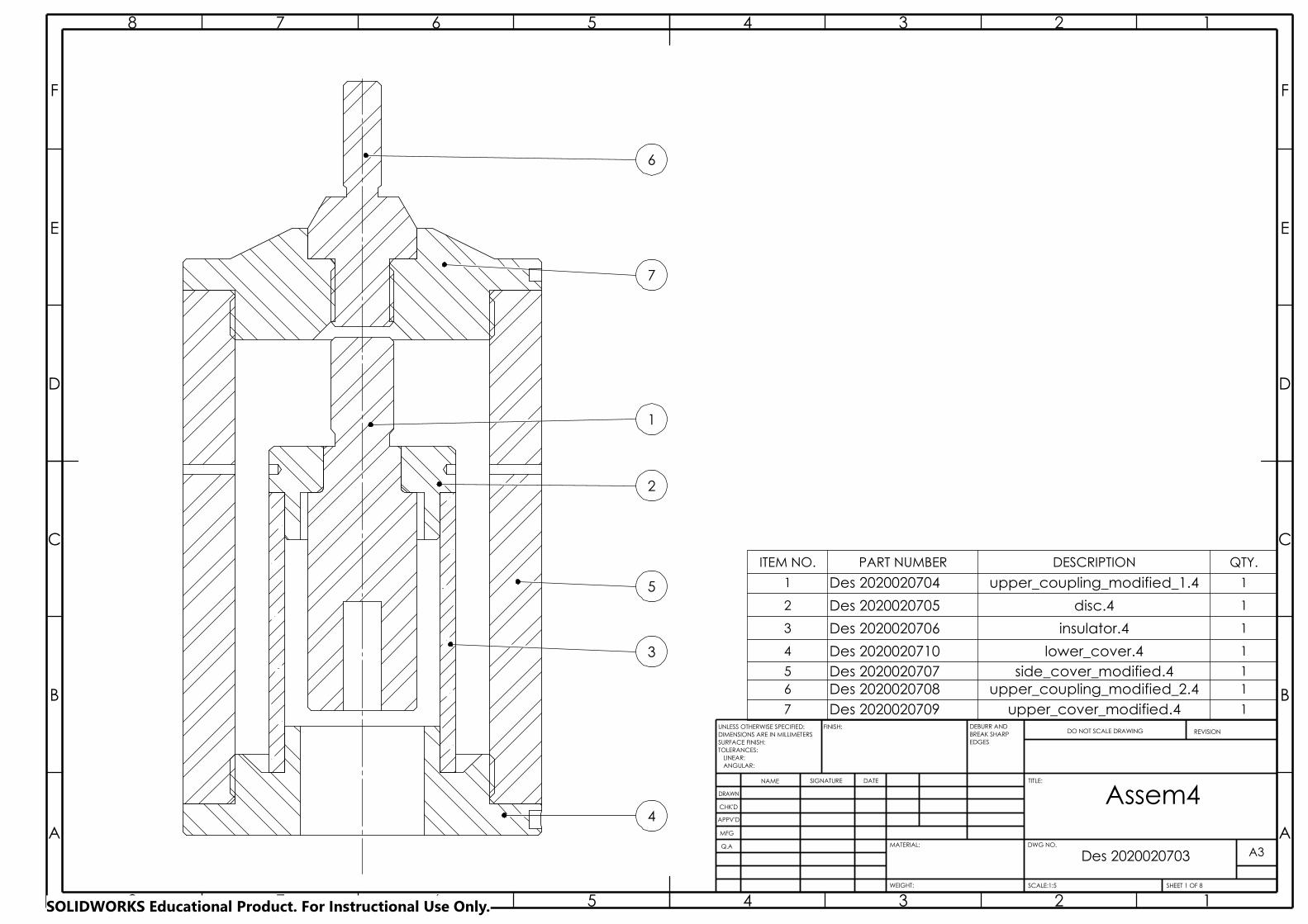
Des 2020020703
A A
B B
C C
D D
E E
F F
8
8
7
7
6
6
5
5
4
4
3
3
2
2
1
1
DRAWN
CHK'D
APPV'D
MFG
Q.A
WEIGHT:
A3
SHEET 1 OF 8SCALE:1:5
DWG NO.
ANGULAR:
FINISH:
LINEAR:TOLERANCES:
EDGES
NAME SIGNATURE DATE
MATERIAL:
DO NOT SCALE DRAWING REVISION
TITLE:
UNLESS OTHERWISE SPECIFIED:DIMENSIONS ARE IN MILLIMETERSSURFACE FINISH:
DEBURR AND BREAK SHARP
Assem4
ITEM NO. PART NUMBER DESCRIPTION QTY.
1 Des 2020020704 upper_coupling_modified_1.4 1
2 Des 2020020705 disc.4 1
3 Des 2020020706 insulator.4 1
4 Des 2020020710 lower_cover.4 1
5 Des 2020020707 side_cover_modified.4 16 Des 2020020708 upper_coupling_modified_2.4 1
7 Des 2020020709 upper_cover_modified.4 1
6
3
7
5
1
2
4
SOLIDWORKS Educational Product. For Instructional Use Only.
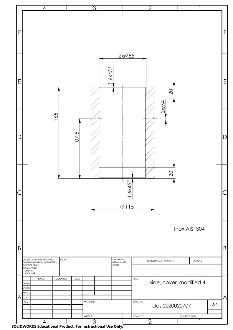
20
20
2xM85
107
.5
165
1
.6x4
5
1.6
x45
2xM
4
115
Inox AISI 304
Des 2020020707
A A
B B
C C
D D
E E
F F
4
4
3
3
2
2
1
1
DRAWN
CHK'D
APPV'D
MFG
Q.A
WEIGHT:
A4
SHEET 2 OF 8SCALE:1:2
DWG NO.
ANGULAR:
FINISH:
LINEAR:TOLERANCES:
EDGES
NAME SIGNATURE DATE
MATERIAL:
DO NOT SCALE DRAWING REVISION
TITLE:
UNLESS OTHERWISE SPECIFIED:DIMENSIONS ARE IN MILLIMETERSSURFACE FINISH:
DEBURR AND BREAK SHARP
side_cover_modified.4
SOLIDWORKS Educational Product. For Instructional Use Only.

4
A-A (2 : 1)
3x 6
15
40 1
6
M85
115
3x
0.4
6
45°
35
10
50.0 --0.2
1x4
5
2
Inox AISI 304
Des 2020020710
A A
B B
C C
D D
E E
F F
4
4
3
3
2
2
1
1
DRAWN
CHK'D
APPV'D
MFG
Q.A
WEIGHT:
A4
SHEET 3 OF 8SCALE:1:2
DWG NO.
ANGULAR:
FINISH:
LINEAR:TOLERANCES:
EDGES
NAME SIGNATURE DATE
MATERIAL:
DO NOT SCALE DRAWING REVISION
TITLE:
UNLESS OTHERWISE SPECIFIED:DIMENSIONS ARE IN MILLIMETERSSURFACE FINISH:
DEBURR AND BREAK SHARP
lower_cover.4
SOLIDWORKS Educational Product. For Instructional Use Only.

M20
4
Des 2020020709
A A
B B
C C
D D
E E
F F
4
4
3
3
2
2
1
1
DRAWN
CHK'D
APPV'D
MFG
Q.A
WEIGHT:
A4
SHEET 4 OF 8SCALE:1:2
DWG NO.
ANGULAR:
FINISH:
LINEAR:TOLERANCES:
EDGES
NAME SIGNATURE DATE
MATERIAL:
DO NOT SCALE DRAWING REVISION
TITLE:
UNLESS OTHERWISE SPECIFIED:DIMENSIONS ARE IN MILLIMETERSSURFACE FINISH:
DEBURR AND BREAK SHARP
upper_cover_modified.4
45
115
M85
35H7
16
10
6x4
5
36
154
1x4
5 2
Inox AISI 304
B-B (2 : 1)
3x 4
SOLIDWORKS Educational Product. For Instructional Use Only.
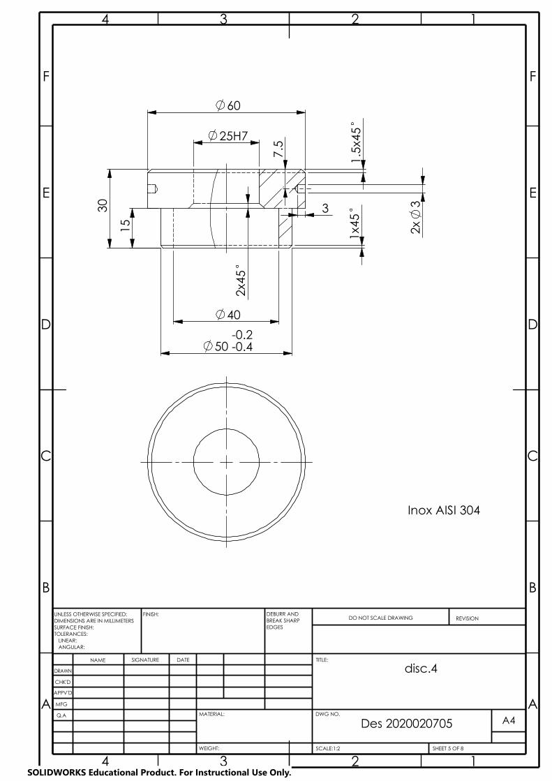
Des 2020020705
A A
B B
C C
D D
E E
F F
4
4
3
3
2
2
1
1
DRAWN
CHK'D
APPV'D
MFG
Q.A
WEIGHT:
A4
SHEET 5 OF 8SCALE:1:2
DWG NO.
ANGULAR:
FINISH:
LINEAR:TOLERANCES:
EDGES
NAME SIGNATURE DATE
MATERIAL:
DO NOT SCALE DRAWING REVISION
TITLE:
UNLESS OTHERWISE SPECIFIED:DIMENSIONS ARE IN MILLIMETERSSURFACE FINISH:
DEBURR AND BREAK SHARP
disc.4
Inox AISI 304
15
60
0.20.4
40
25H7
--
30
1x4
5
3
2x4
5
1.5
x45
50
2x
3
7.5
SOLIDWORKS Educational Product. For Instructional Use Only.

Des 2020020704
A A
B B
C C
D D
E E
F F
4
4
3
3
2
2
1
1
DRAWN
CHK'D
APPV'D
MFG
Q.A
WEIGHT:
A4
SHEET 6 OF 8SCALE:1:1
DWG NO.
ANGULAR:
FINISH:
LINEAR:TOLERANCES:
EDGES
NAME SIGNATURE DATE
MATERIAL:
DO NOT SCALE DRAWING REVISION
TITLE:
UNLESS OTHERWISE SPECIFIED:DIMENSIONS ARE IN MILLIMETERSSURFACE FINISH:
DEBURR AND BREAK SHARP
upper_coupling_modified_1.4
Inox AISI 304
-0.020
50
R1.5
35
35
M20
4
-0.007
120
25 g6
1x4
5
SOLIDWORKS Educational Product. For Instructional Use Only.
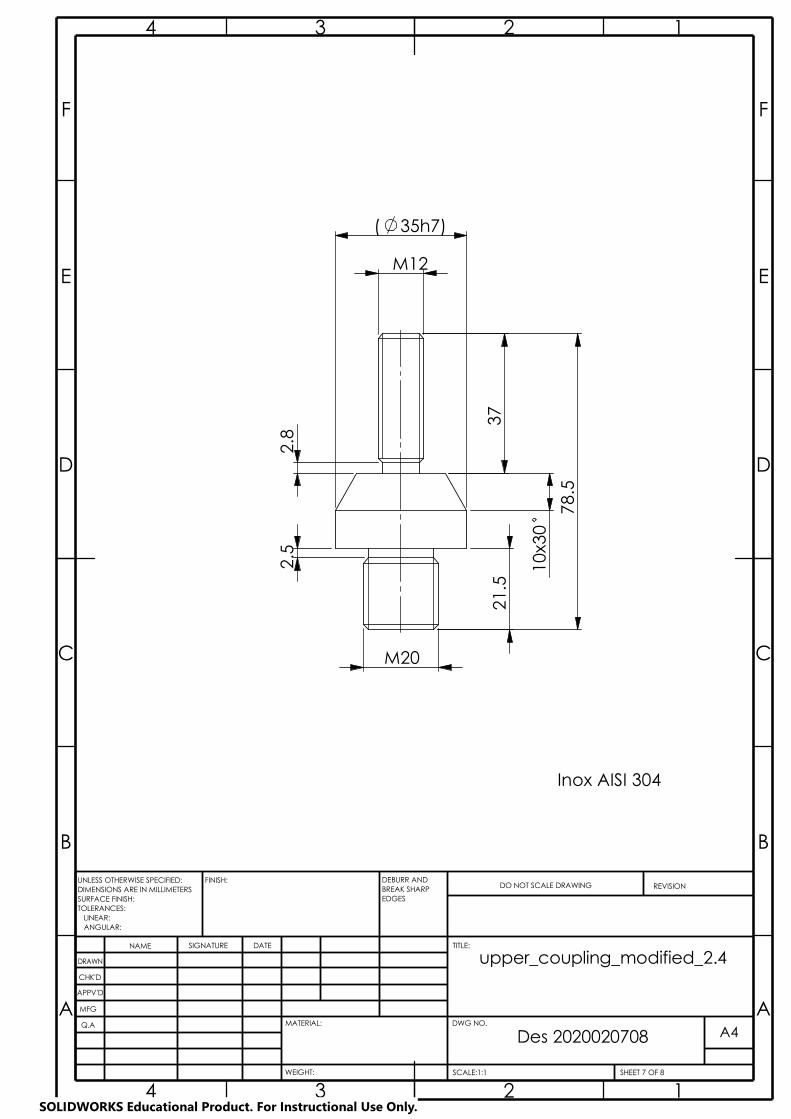
A A
B B
C C
D D
E E
F F
4
4
3
3
2
2
1
1
DRAWN
CHK'D
APPV'D
MFG
Q.A
UNLESS OTHERWISE SPECIFIED:DIMENSIONS ARE IN MILLIMETERSSURFACE FINISH:TOLERANCES: LINEAR: ANGULAR:
FINISH: DEBURR AND BREAK SHARP EDGES
NAME SIGNATURE DATE
MATERIAL:
DO NOT SCALE DRAWING REVISION
TITLE:
DWG NO.
SCALE:1:1 SHEET 7 OF 8
A4
WEIGHT:
Des 2020020708
upper_coupling_modified_2.4
Inox AISI 304
( 35h7)
2.8
M12
37
2.5
21.
5
78.
5
10x
30
M20
SOLIDWORKS Educational Product. For Instructional Use Only.
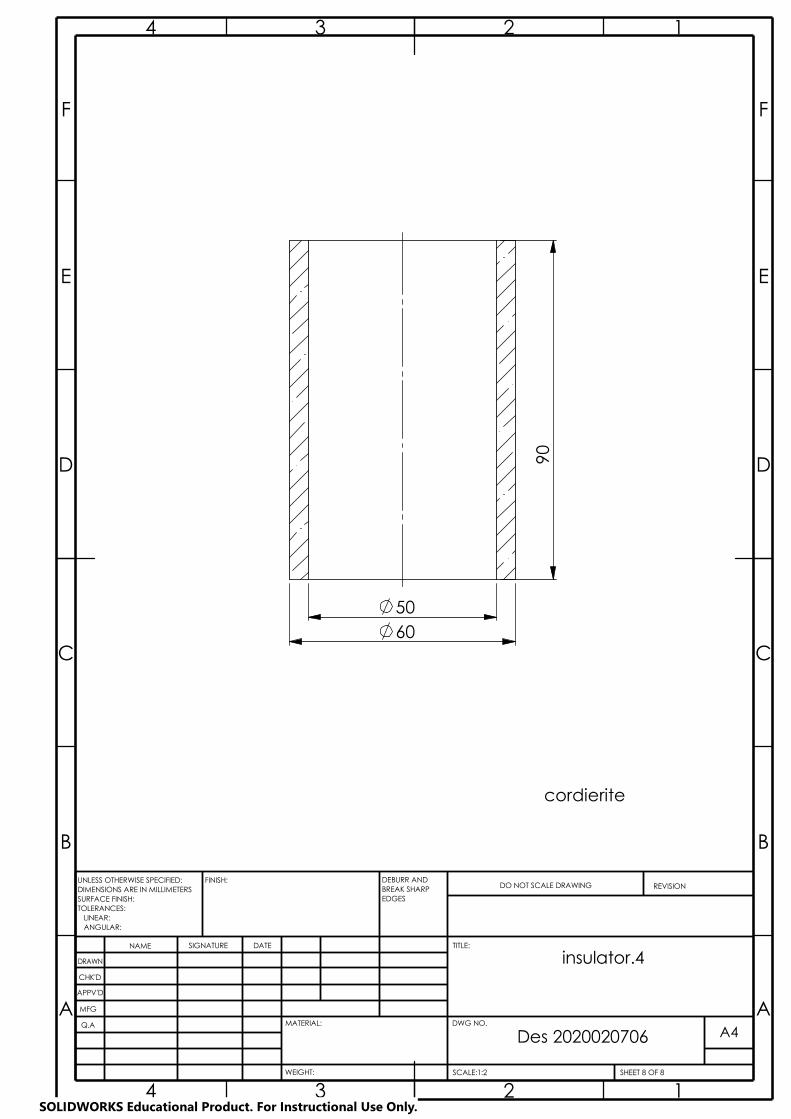
A A
B B
C C
D D
E E
F F
4
4
3
3
2
2
1
1
DRAWN
CHK'D
APPV'D
MFG
Q.A
UNLESS OTHERWISE SPECIFIED:DIMENSIONS ARE IN MILLIMETERSSURFACE FINISH:TOLERANCES: LINEAR: ANGULAR:
FINISH: DEBURR AND BREAK SHARP EDGES
NAME SIGNATURE DATE
MATERIAL:
DO NOT SCALE DRAWING REVISION
TITLE:
DWG NO.
SCALE:1:2 SHEET 8 OF 8
A4
WEIGHT:
Des 2020020706
insulator.4
cordierite
90
50 60
SOLIDWORKS Educational Product. For Instructional Use Only.