THE STRUCTURE OF PEROVSKITE-LIKE CÆSIUM PLUMBO …gymarkiv.sdu.dk/MFM/kdvs/mfm...
28
Matematisk-fysiske Meddelelse r udgivet af Det Kongelige Danske Videnskabernes Selska b Bind 32, nr . 2 Mat. Fys. Medd . Dan . Vid . Selsk . 32, no .2 (1959 ) THE STRUCTUR E OF PEROVSKITE-LIKE CÆSIU M PLUMBO TRIHALIDE S B Y CHRISTIAN KN . MØLLE R København 195 9 i kommission hos Ejnar Munksgaard
Transcript of THE STRUCTURE OF PEROVSKITE-LIKE CÆSIUM PLUMBO …gymarkiv.sdu.dk/MFM/kdvs/mfm...
Matematisk-fysiske Meddelelserudgivet af
Det Kongelige Danske Videnskabernes SelskabBind 32, nr . 2
Mat. Fys. Medd . Dan . Vid . Selsk . 32, no .2 (1959 )
THE STRUCTURE
OF PEROVSKITE-LIKE CÆSIUM
PLUMBO TRIHALIDE S
B Y
CHRISTIAN KN. MØLLER
København 195 9i kommission hos Ejnar Munksgaard

Synopsis
Crystalline compounds of composition CsPbX 3 , where X = Cl or Br, may b eprepared either from aqueous solutions or by fusing CsX and PhX 2. The pal eyellow CsPbC1 3 has cubic perovskite structure above 47°C . (a = 5 .605 A), theorange-coloured CsPbBr 3 above 130°C . (a = 5 .874 A). Below these temperaturesthe structures are slightly distorted, but apparently without changes of volum eat the transition points . CsPbBr 3 below 130°C . (and possibly also CsPbCls below47°C .) exhibits a superstructure, but not above this temperature . Application o fFourier methods shows that above as well as below the transition points, bot hthe halogen atoms and the Cs-atoms are a little displaced from those position sexpected for an ideal perovskite structure . Structure factors have been calcu-lated on the assumption that each halogen atom occupies one of four, each Cs-atom one of six close-lying potential-minima at random ; they show excellen tagreement with the observed structure factors . Tt is suggested that such a de-localization of certain atoms may be a common feature in cubic perovskite struc-tures where the tolerance factor t $ 1 . The PbCl-distances are 2 .86 Å and th ePbBr-distances 2 .99 A, i .e . considerably shorter than the sum of the correspondin gionic radii .
Printed in DenmarkBianco Lunos Bogtrykkeri A-S
Introduction
It has been demonstrated in a previous paper s that CsPbI 3 can exis t
in a black perovskite-like modification besides the yellow, orthorhombi c
form stable under ordinary conditions . It will be shown in the presen t
study that CsPbC13 and CsPbBr3 also form perovskite-like structures whic h
in this case are the stable modifications. CsPbF 3 has already been found b y
O. SCIIMITZ-DUMONT and G . BERGERHOFF to belong to this structure type 2
with the unit cell edge a = 4 .80 kX.Ideally, crystals with perovskite structure are cubic with one molecul e
in the unit cell, 3 but very often small deviations from cubic symmetry are
found. However, in such cases there usually is a transition temperatur e
above which the structure is strictly cubic . 4 With only one molecule ABX3in a cubic unit cell one would expect that all the atomic positions wer e
fixed by symmetry . This argument has been widely used, but may no t
always be applicable for the following reasons . It is known that alloys exist
which exhibit a cubic structure, but where the cubic symmetry is of a sta-tistical nature so that the distribution of atoms within only one unit cell a t
definite lattice sites need not at all conform to the observed "average sym-
metry
Secondly, it is generally agreed that crystals with perovskite structur ebelong to the so-called defect structures, 3 and as far as the author is aware ,
the nature of the defects in this case is not yet understood .If we imagine the ions to be solid spheres with definite ionic radii rA , rB ,
and rX the following relation can easily be demonstrated for the idea l
perovskite structure :
C . K . MØLLER, The Structure of CsPbI.3 , Mat . Fys . Medd . Dan. Vid . Selsk . 32, No . 1 (1959) .2 O . SCHMITZ-DUMONT and GUNTHER BERGERI-TOFF, Z . anorg. u . allgem. Chem. 283, 314-329
(1956) .3 See e. g . (a) . R . C . RvANS, Crystal Chemistry p .204-214, Cambridge 1939 . (b) A. F .
WELLS, Structural Inorganic Chemistry p . 112, P . 330, Oxford 1945 .4 H.D . MEGAw, Ferroelectricity in crystals, Chapters 4 and 5 . Methuen, London 1957 .b See e .g . Ref . 3a p . 109 .
1*

rA +rx°
1/-2-.t ,
rB+rx
where t = 1 . However, for many crystals with perovskite structure t willbe found to be different from 1 - usually in the range 0 .8 < t <1 when w e
insert the generally accepted ionic radii . '
We can interpret this either as an observable effect of the defect nature
of these crystals, or as an indication that the ions are not solid spheres wit h
fixed ionic radii . In fact, it has been proposed to use special ionic radi i
for ions when they form crystals of this type,' but from the observation s
to be described in what follows this procedure does not seem to be recom-mendable. It is presumably true that the bonding between the atoms i n
perovskite structures is mainly ionic and may be modified by polarizatio n
so that the interatomic distances will be shorter than calculated from theordinary ionic radii, but this can scarcely justify the use of separate "perov-skite ionic radii" .
In order to clarify some of the problems connected with the perovskit e
structure a detailed investigation has been made of CsPhC13 and CsPbBr 3 ,as will now be described .
Preparation and general propertie s
As has been shown by H . L . WELLS 3 and coworkers crystals with th e
compositions CsPbC1 3 and CsPbBr, can be prepared by dissolving PbC1 2 ,
resp . PbBr 2 , in a hot aqueous solution of CsCl, resp . CsBr, of suitable
concentration and then left to cooling . Besides this method of preparatio n
we have found that compounds of the type CsPbX 3, where X = Cl, Br, or
I can also be obtained by fusing CsX and PbX 2 in the correct stoichiometri c
proportion . The identity of the crystalline compounds prepared by eithe r
method was proved by the identity of their X-ray powder diagrams an d
transition temperatures (see below) .
The crystals grown in solution are quadratic or rectangular in shape,those of CsPbC13 pale yellow and those of CsPbBr 3 orange coloured . Their
refractive indices are high, above 1 .74 .
Although the crystals are decomposed by water it was possible to deter -
mine the density of CsPbC1 3-crystals by the flotation method in a Clerici ' s
V . M . GOLDSCHMIDT, Z . tech . Phys . 8, 256 (1927).2 S. GELLER, Acta Cryst . 10, 248 (1957) .
Fi . L . WELLS, Z . anorg . Chem. 3, 195 (1893) .
(1)
Nr. 2
5
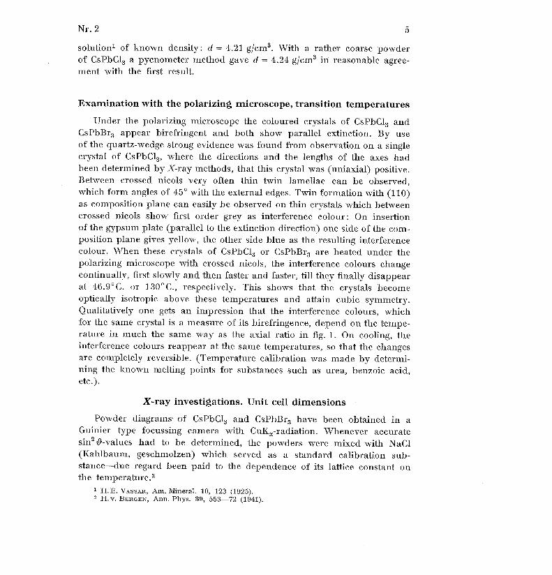
solution s of known density : d = 4 .21 g/cm3. With a rather coarse powderof CsPbC13 a pycnometer method gave d = 4 .24 g/cm3 in reasonable agree -ment with the first result .
Examination with the polarizing microscope, transition temperature s
Under the polarizing microscope the coloured crystals of CsPbC1 3 andCsPbBr3 appear birefringent and both show parallel extinction . By useof the quartz-wedge strong evidence was found from observation on a singl ecrystal of CsPbC13, where the directions and the lengths of the axes ha dbeen determined by X-ray methods, that this crystal was (uniaxial) positive .Between crossed nicols very often thin twin lamellae can be observed ,which form angles of 45° with the external edges . Twin formation with (110 )as composition plane can easily be observed on thin crystals which betwee ncrossed nicols show first order grey as interference colour : On insertionof the gypsum plate (parallel to the extinction direction) one side of the com-
position plane gives yellow, the other side blue as the resulting interferencecolour. When these crystals of CsPbC13 or CsPbBr3 are heated under thepolarizing microscope with crossed nicols, the interference colours chang econtinually, first slowly and then faster and faster, till they finally disappea rat 46 .9°C . or 130°C ., respectively . This shows that the crystals becom eoptically isotropic above these temperatures and attain cubic symmetry .Qualitatively one gets an impression that the interference colours, whic hfor the same crystal is a measure of its birefringence, depend on the tempe -rature in much the same way as the axial ratio in fig . 1 . On cooling, th einterference colours reappear at the same temperatures, so that the change sare completely reversible . (Temperature calibration was made by determi-ning the known melting points for substances such as urea, benzoic acid ,etc .) .
X-ray investigations. Unit cell dimensions
Powder diagrams' of CsPbC1 3 and CsPbBr 3 have been obtained in aGuinier type focussing camera with CuKa-radiation . Whenever accurat esin 2 &-values had to be determined, the powders were mixed with NaC l(Kahlbaum, geschmolzen) which served as a standard calibration sub-stance-due regard been paid to the dependence of its lattice constant o nthe temperature . 2
s H.E . VASSAR, Am . Mineral . 10, 123 (1925) .2 H . v . BERGEN, Ann . Phys . 39, 553-72 (1941) .

6
Nr . 2
In order to obtain diagrams of the powders at elevated temperature sthe sample was fixed with the smallest possible amount of Canada balsa mon a thin cover glass . This was squeezed into position between the circula rmetal holder and a piece of perforated mica with 6-7 turns of a 0 .2 mmthick Ni-Cr-wire which could be electrically heated . It was found that th ehot wire did not seriously affect the X-ray diagrams when it was kep tperpendicular to the cylinder axis of the curved quartz-monochromator ,and hence the samples were kept stationary, not rotated as is usual duringthe exposures . The temperatures were estimated from measurements of th eresistance of the hot wire during operation, the transition temperaturesdetermined by the optical investigation above being used as fix points .
Indices could be assigned to the "reflections" on the powder diagram sby application of the general formul a
sin2'O _~2 ( 1 h2 + 12 1
122 cos y
Izk },
(2)4 l a 2 sin2 y
b 2 sin2 y
c 2
ab sin2
JJJ
where in our case y was either 90° or very close to 90° and a = h c. Thelattice constants for the crystals at different temperatures were finally eva-luated from the coefficients to h2, 1 2 and hk in (2) giving best agreementbetween observed and calculated sin2 19-values . They are reproduced to-gether with indices, estimated intensities, and sin 2 l-values in Tables 1 and 2(A (Cute) = 1 .5418 Å) .
A few diffuse lines on the Guinier-diagrams of CsPbBr 3 below the transi-tion temperature (130°C.) cannot be accounted for with the indexing i nTable 2 unless the unit cell axes are doubled . However, in order to maintai nthe connection with the cubic unit cell, instead of doubling the axes we havechosen to use fractional indices for these reflections . It is characteristi cof these lines that they decrease in intensity as the crystalline powder i sheated above room temperature, and practically disappear when the unitcell axes become of equal length at 130°C ., only very faint diffuse band sbeing left in their place on the diagrams taken of the cubic form . Fromthis behaviour one would infer that the lines mentioned are due to a super -structure which "melts" in the crystal at 130°C ., only leaving some degre eof "local order" reminiscent of the superstructure .
Also CsPbC1 3 in the tetragonal form shows a few lines of this type, butit is difficult to decide whether they really disappear at 47°C ., and beside sthere are some rather sharp, very weak lines as well, which completel ypersist above 47°C . However, it has turned out that the latter originate from
Nr. 2 7
the compound Cs 4 PbC1 6 which then apparently is present as an impurity
in CsPbC1 3 prepared both from aqueous solution and by fusing CsCl an d
PbCl 2 .
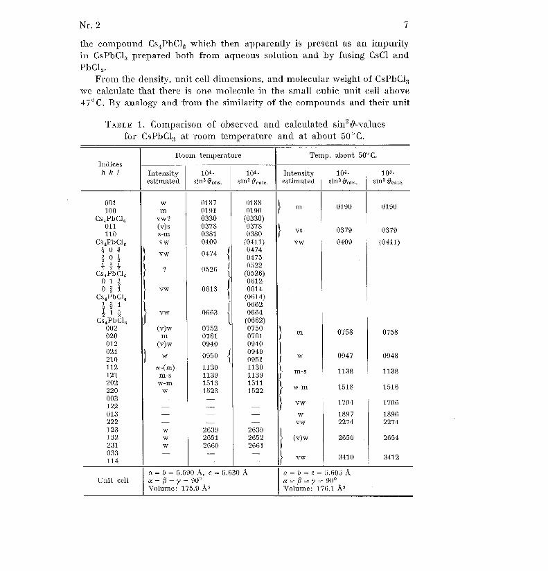
From the density, unit cell dimensions, and molecular weight of CsPbC13we calculate that there is one molecule in the small cubic unit cell abov e
47°C. By analogy and from the similarity of the compounds and their unit
TABLE 1 . Comparison of observed and calculated sin 2~-values
for CsPbC1 3 at room temperature and at about 50°C .
Room temperature Temp. about 50°C .Indicesh k I Intensity
estimated10 4 •
sins 99° ~,5,10 4 •
sin' ~ eaie,Intensityestimated
104 •
sin s 19,01,s .104 •
sin 2 ~cale .
00 110 0
Cs 4 PbC1 601 111 0
Cs 4 PbC1 6
2 00 i4
Cs 4 PbC1 60 1 L0 z 1
Cs 4PbC1 6
~ ~ 1t,
1
åCs 4PbC1 6
00 202 001 2
~011 212 120 222 000 312 201 322 2123132231033114
wm
vw ?(v) ss-mv w
Î
v w
L
?f
1
vw~
v w
(v)wm
(v)w
~
w
w-(m )m- sw- m
w
--www-
018 7019 1033 0037 8038 1040 9
0474
{
0526
f1
0613
1~
066 3
075 2076 1094 0
0950
{11301139151 3152 3
-263 9265 1266 0--
018 8019 0
(0330 )037 8038 0
(0411 )047 4047 50522
(0526)061 2061 4
(0614 )066 2066 4
(0662 )075 0076 1094 0
00949
95 111301139151 11522
-
-263 9265 2266 1--
1
mJ
~
v svw
~
4nf
~
w1
m- sflj
w m
~
v ww
vw
~
(v) w
vw
019 0
037 9
040 9
075 8
094 7
113 8
151 8
170 4
189 7227 4
265 6
3410
0190
037 9
(0411 )
075 8
0948
113 8
151 6
170 6
18962274
2654
341 2
n=6=5.590Å, c=5 .630Å a=6 =c= 5 .605 ÅUnit cell a = ß = y 90 °a=ß=y=90 °
Volume : 175 .9 A s Volume : 176 .1 Å 3
8 N r . 2
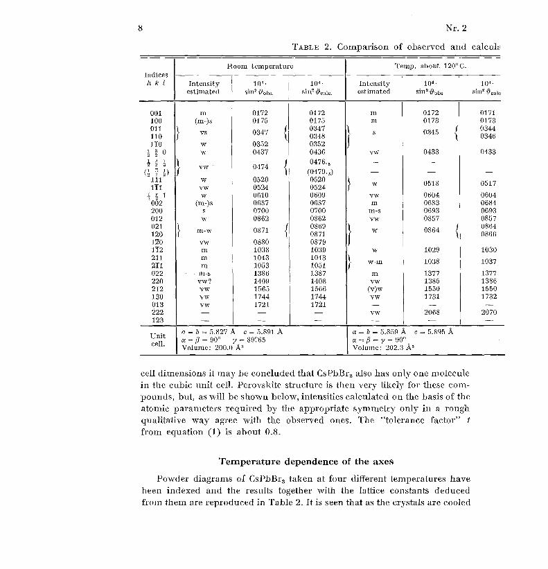
TABLE 2 . Comparison of observed and calcul a
Indice sh k 1
Room temperature Temp . about 120°C .
Intensity 10 4 • 10 4 - Intensity 104 - 10 4 •
estimated sin 2 Oobs . estimated sin 2 4iobs . sin 2 ~°,,i°
001 m 0172 0172 m 0172 017 1100 (m-)s 0175 0175 m 0173 017 3011 0347 034 4
vs}
0347
~s 034 5
110 0348 034 6110 w 0352 0352
i 4 0 w 0437 0436 vw 0433 043 3
-IT
i 0476 . 5 - - -
(z i z)~
vw 0474(0479, 5 ) - -
111 w 0520 0520w 0518 051 7
111 vw 0524 052 4Z L 1 w 0610 0609 vw 0604 0604
002 (m-)s 0687 0687 m 0683 0684200 s 0700 0700 m-s 0693 069 3012 w 0862 0862 vw 0857 085 7021 0869 0864
m-w 0871 w 0864{120 0871 086 6
120 vw 0880 087 9112 m 1038 1039 w 1029 103 0211 m 1043 1043 l
w-m 1038 103 7211 m 1053 1051 f022 m-s 1386 1387 m 1377 137 7220 vw? 1409 1408 vw 1385 138 6212 vw 1565 1566 (v)w 1550 155 0130 vw 1744 1744 vw 1731 173 2013 vw 1721 1721 -222 - - - vw 2068 207 0123 - - - - - -
a= b =5.827Å
c=5.891Å a = b =5.859Å
c=5.895 Åuni
cellt a=ß=90°
y = 89?65 a=ß =y=90°Volume : 200 .0 Å 3 Volume : 202 .3 Å3
cell dimensions it may be concluded that CsPbBr 3 also has only one molecule
in the cubic unit cell . Perovskite structure is then very likely for these com-pounds, but, as will be shown below, intensities calculated on the basis of th e
atomic parameters required by the appropriate symmetry only in a rough
qualitative way agree with the observed ones . The "tolerance factor" t
from equation (1) is about 0 .8 .
Temperature dependence of the axes
Powder diagrams of CsPbBr 3 taken at four different temperatures hav e
been indexed and the results together with the lattice constants deduce d
from them are reproduced in Table 2 . It is seen that as the crystals are coole d

Nr. 2. 9
'0-values for CsPbBr 3 at different temperatures .
Temp. about 125°C. Temp . about 135°C .Indice s
ntensityïtimated
10 4 •
sin' i~i,bs,
10 4 •
sin'~Q
u Calc .
Intensityestimated
10~p4 •
sin' V' obs.
10p4 •
sin' 1~cal °.h k 1
m-s 0172 0172 m 0172 017200110 0
0345s 0344
{ 0346 }
s 0345 0344 011 0110
a- - z i 0_ _ _
zi
s.
1-i (l I _ )
m-w 0516 0517 w 0516 051611 111 1
- - åz lm 0688 0687
0689 068900 2
m-s 0692 0691s
~ 20 0(v)w 0861 0860 01 2
w 0865 0864ni 0862 0861
02 112 0120
(1033) 112m-s 1036 1036 ~
m-s 1035 1035 21 121 1
m-s 1379
~111
1382 ~
ni-s 1379 1378 022 0vw 1551 1551 w-in 1546 1550 21 2vw 1725 1728 13 0vw
11721 1722
01 3vw 2069 2067 vw 2065 2066 22 2vw c .2400 2408 vw 2411 2411 12 3
=b=5.s64Å
c=5.881Å a = b =5.874 Å== ^1 = 90° a = Y =90°
Unit
Mime : 202 .2 Å3 Volume : 202 .7 Å3cell .
from temperatures above 130°C . the unit cell changes from cubic throug h
tetragonal to monoclinic symmetry at room temperature . Although thechanges of the axes are easily demonstrated, the change of volume of th e(pseudo-)unit cell when the transition point at 130°C. is passed, presum-
ably is not significant .Instead of making a similar investigation on powders of CsPbC1 3 at severa l
different temperatures, which would be rather time-consuming, it was chose nto measure the changes of the axes of a single crystal . The crystal was care -fully adjusted on a Weissenberg goniometer and a series of 3° oscillatio nphotographs were taken of the reflections 071 and 017, which have 20 . -155 0 for CulÇ radiation. The layer-line screen was used to separate th ezeroth layer line, and the film cylinder (diameter 57 .3 mm) was kept

10
Nr. 2
stationary for each pair of exposures : 071 at the "top" and the "bottom "of the film . Then the film cylinder was displaced 3 .0 mm (the width of theslot in the layer-line screen) and the oscillation regions of the crystal change d
so that now two similar exposures could be taken of 017 at the same tempe -rature. After that the temperature was changed, the film cylinder displace d3 .0 mm, and a set of four exposures taken at the new temperature, and s o
on. Exposure times were about 10 minutes .
The crystal could be heated by a controlled stream of N 2 from a cylinder ,passing a flowmeter and a very small, electrically heated "oven " , which
was placed immediately in front of the crystal . Temperature control wa s
afforded by a copper-constantan thermocouple in connection with a milli -
voltmeter . The oven-current could be read on an ammeter . Calibration wa smade in the following way . Two small polaroids were placed on either side
of the crystal, "crossed", but with maximum light passing through the crysta l
when it was illuminated with a beam of light through the pin-hole syste mof the goniometer, and the crystal was watched through the microscop e
attached to the goniometer . With constant N 2-flow the oven-current was
slowly increased till the crystal just became dark (optically isotropic) . Thetemperature must then be 47°C. For the same rate of flow of N 2 and nearly
constant room temperature it was then assumed that there was linea r
dependence between the thermoelectric power of the thermocouple an d
the temperature of the crystal for not too wide a range of temperatures .The relation between the changes in glancing angles measured on
the film and the changes in axial lengths is obtained from (2) by differ-
entiation . For 071 and 017 and with 4 c -2 J a it approximates t o
4a= -1 .06 a cot9-Af and 4c= -1 .03 a cotf•4m,
(3 )
where, with sufficient accuracy, a c 5 .60 A, as the total uncertainty on
4 a and 4 c is of the order of 10 per cent .
Similarly the change of the axial ratio is given by
4 (-c ) - 1 (4 c-4 a) .a
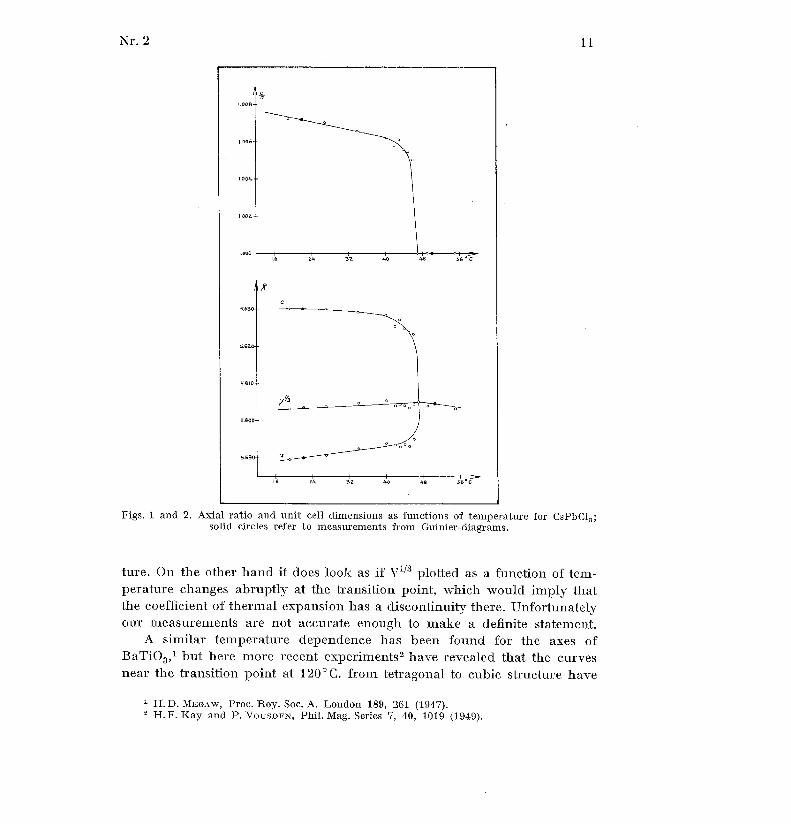
The results obtained are shown in the graphs figs . 1 and 2, where the
values of the axes at room temperature and at 50°C . have been adjustedso as to coincide with the values from the Guinier diagrams mentioned
above . It appears that neither for CsPhC13 is there any discernible chang e
of the volume, V, at the transition point from the tetragonal to cubic struc -
(4)
Nr . 2
1 1
Figs . 1 and 2 . Axial ratio and unit cell dimensions as functions of temperature for CsPbC1 3 ;solid circles refer to measurements from Guinier-diagrams .
ture . On the other hand it does look as if v'73 plotted as a function of tem -perature changes abruptly at the transition point, which would imply tha tthe coefficient of thermal expansion has a discontinuity there . Unfortunatelyour measurements are not accurate enough to make a definite statement .
A similar temperature dependence has been found for the axes o fBaTiO 3 , 1 but here more recent experiments 2 have revealed that the curvesnear the transition point at 120°C. from tetragonal to cubic structure have
H.D. MEGAW, Proc . Roy . Soc . A . London 189, 261 (1947) .2 H.F . Kay and P . VOUSDEN, Phil . Mag. Series 7, 40, 1019 (1949) .

12
Nr . 2
discontinuities and also that thermal hysteresis plays a rôle . It is possible
that a more refined technique will disclose similar irregularities also i n
the case of CsPbC1 3 .
Intensity measurements
In order to study the atomic arrangement in more detail, intensit y
measurements of the X-ray reflections on Weissenberg diagrams have bee nmade on single crystals of CsPbC1 3 and CsPbBr 3 , by means of CuK a-radia-tion . The reflections were photographed on sets of multiple filins and relative
intensities were visually estimated by comparison with an intensity scaleprepared by taking a series of photographs of a particular reflection, eac htime increasing the exposure time by about 30 per cent . The intensitie s
of these spots were then assumed to be proportional to their exposur e
times. Care was taken that X-ray intensity, temperature, speed of the Weis-senberg motor, developer, fixer, and film material were kept as constantas possible . A new intensity scale was made for each crystal .
In order to check the reliability of this method two independent set sof measurements were made of the 0 . and 1 . layer lines of two different
crystals of CsPbC1 3 at room temperature . One had the dimensions 100x 5 0
x 40y and the other 100 x 40 x 30, u . The longest edge was the rotation axis .The agreement was found to be good, only in one case of 45 reflection s
measured was the deviation above 30 per cent, on an average it was abou t
12 per cent. of the measured intensity .
The reflections from a single crystal of CsPbC1 3 (and similarly of CsPbBr 3 )
were photographed with CuKa-radiation both at room temperature (20°C . )and at 7-10 centigrades above the transition point on the same set of mul-
tiple films. This was achieved by displacing the film cylinder 3 .0 mm inits carriage between the two exposures . In this way intensity changes whichmight be observed of the reflections, should be influenced least possibl e
by film material and development. Heating and temperature control was
performed as explained above . The "high-temperature" reflections gavesmall, well-defined spots on the film, with a uniform blackening. But on
the room-temperature exposures of CsPbBr3, these spots had broken u p
into 3-4 smaller spots lying close together, so that it was necessary to ad d
up the intensities of the separate spots belonging to the same reflection .On heating the crystal to temperatures above 130°C. these spots again
coalesced, showing that it is a reversible phenomenon . The reason for it soccurrence is that when the crystals are cooled from temperatures wher ethe unit cell is strictly cubic to room temperature the unit cell is slightly
Nr . 2
1 3
modified by expansion of, say, the original a-axis and shrinkage of it stwo other axes. However, in other parts of the "single crystal" the expansio nmay be along the original b or c-axis (and shrinkage along the two others )and thus the result is a repeated twinning and microheterogeneity. l Asimilar effect could be observed on some of the diagrams of CsPbC1 3 , butwas there much less pronounced . For the particular crystal used it coul dalso be inferred from the fact that on heating from room temperature toabout 55°C. the reflections of type 0kO were always displaced towardssmaller, those of type 001 towards higher s9-values, that twinning could no the of major importance here .
The atomic scattering factors depend on the wavelength of the X-ra yradiation used (dispersion), as do also the absorption corrections, and s oit is conceivable that a more shortwaved radiation would give results dif-ferent from those obtained with CulÇ radiation. Therefore photographswere also taken of CsPbBr 3 at 140°C. with MoK a-radiation for intensitymeasurements .
Correction of the directly measured intensities for the Lorentz-polariza-tion factors was made graphically as described by Cochran .' It was pre-viously found that the absorption of X-radiation in CsPbI 3 was compensatedfor by the temperature factor and could be included in the latter .' As thisresult presumably will also be valid here, we have made no direct correction sfor the absorption . We thus finally obtain relative IF(hkl)1
2-values of which
the uncertainty is assumed not to exceed 20-30 per cent .As no piezoelectric effect has been detected in these crystals, neithe r
with a dynamical' nor with a static method, it seems reasonable to con-clude that they have centres of symmetry and consequently F(hkl) _
FF(hkl) I .
Application of Fourier method sWith only one molecule CsPbX 3 in a cubic unit cell the atomic positions
should be determined by symmetry. Thus we may have :
Pb in (0, 0, 0) ; Cs in (-2' 2 , ~) ; X in (2-, 0, 0) ; (0,
0) ; (0, 0,
(a )
or Pb in (0, 0, 0) ; Cs in 1 1 1 1 X in
0 1
1
0 . (b)2 2 2
(o,2 2) ' (2 '
2)' (2 ' 2' )Compare V.K . SEMENCHENKO, J . Cryst . U .S .S .R . 2, 145 (1957) .
2 W . COCHRAN, J . Set . Instr. 25, No . 7 (1948).3 C . K . MØLLER, loc. cit. p . 11 .4 V . FRANK, Unpublished work .
14
Nr. 2
Structure factors calculated on the basis of (a) with atomic scattering fac-
tors corrected for dispersion' do not give a very good agreement with th eexperimentally determined structure factors (Tables 3 and 4 ; Column 2to be compared with Columns 4 and 5 ; see also figs . 8 and 9) . The secondpossibility, (b), which is also equivalent to an interchange of Cs and Pbin (a), is even less satisfactory, and, furthermore, Pb would here acquirea coordination number 12, which seems rather unlikely .
Let us assume that Pb is correctly placed in (0, 0, 0), which is a centr eof symmetry . As the atomic scattering factor of lead for the reflections o ftype Okl exceeds the sum of the atomic scattering factors of Cs and 3 X,
the structure factors F(Okl) must be positive. Hence we can calculate the
electron projection on the bc-plane directly from the observed j F(0ki) I . Thishas been done for both CsPbC13 and CsPbBr3 above their transition tem-
peratures, i . e . in their cubic form, and the result is shown in figs . 3 and 5 .
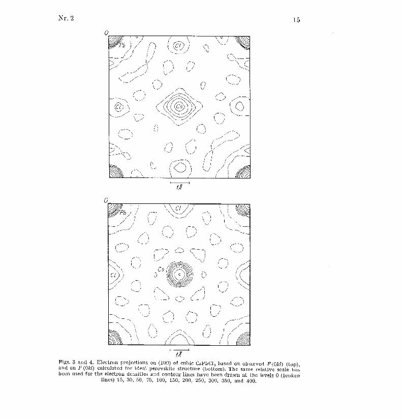
It is seen that the electron clouds surrounding the halogen atoms ar edrawn out at right angles to the unit cell edges . As for the Cs-atoms, thei r
peak heights come out much too low as compared with the peak heigh t
of the Pb-atoms, and on the projection of CsPbCl 3 their electron cloud s
seem to have "spikes " towards the Cl-atoms .
To estimate the contribution of diffraction effects to these somewhat
unexpected results another projection on the bc-plane was calculated fo r
CsPbC1 3 , but now using the structure factors calculated for this compoun dwith the atoms in position (a), instead of the observed F (Oki) as coefficients
in the Fourier series .
This "theoretical" projection faithfully reproduces the atoms in theexpected positions, and with reasonable peak heights . It is also seen thatthere is a definite correlation of the "diffraction errors" in figs . 3 and 4 ,
and it seems evident that they cannot be made responsible for the peculiarfeatures of the "experimental" projections .
An electron projection of CsPbBr3 calculated from structure factors
obtained with MoK IXradiation gives mainly the same result as that base dupon CuK «-radiation . It is thus unlikely that the latter kind of projectio nshould be seriously distorted by dispersion and absorption . This conclu-
sion gets further support from the fact that in the earlier work on CsPbI 3 2
the interpretation of the electron projections derived from intensities wit hCuIÇ-radiation was in no way obscured by any of the effects mentionedabove, although they would be expected to be of greater importance i n
this case .
i Atomic scattering factors were taken from W .H . BRAGG and W.L . BRAGG, The Crystal-line State . Vol . I p . 330-333 (London 1949), corrections for dispersion from G .H. DAUBE Rand D .H . TEmMPLETON, Acta Cryst . 8, 841 (1955) .
2 C . K. MØLLER, loc . cit .
Nr . 2
1 5
0
0
'\_- '
/
,r/
\
-',
/~
,
.,~
~ l\
)`-\
/i ,
_--'..,
\\
t\
1_
,
\1
,'s-
// \
/ri~
~i
)~~.
Figs . 3 and 4 . Electron projections on (100) of cubic CsPbC1 3 based on observed F(Okl) (top) ,and on F(Okl) calculated for ideal perovskite structure (bottom) . The same relative scale hasbeen used for the electron densities and contour lines have been drawn at the levels 0 (broke n
lines) 15, 30, 50, 75, 100, 150, 200, 250, 300, 350, and 400 .

0
/n1
dlFig. 5 . Electron projection on (100) of cubic CsPbBr 3 . Relative, arbitrary scale for electron
density . Contour lines drawn as in figs . 3 and 4.
Finally a projection of tetragonal CsPbC13 has been calculated fromits observed 1 F(Okl) I . The result is almost indistinguishable from that o f
the cubic form. Difference synthesis with the Fourier-coefficients F (Okl)tetr .- F(Okl)ellb, obtained from the experimentally determined intensities fo rthe cubic and tetragonal modifications of both CsPbC1a and CsPbBr 3 alsoshow near identity of the two forms ; in fact, the only observable changes in
the electron distributions on going from the tetragonal to the cubic struc-tures seem to be a reduction in peak height of the Cs-atoms and a smal ldisplacement of the halogen atoms towards the unit cell edges (about 0 .05 Å
in CsPbCl 3 ) .For the interpretation of the above results it should be remembere d
that an electron projection derived from experimental data represents a
superposition of the electron distributions in a huge number of unit cells . We
have so far been referring structures to the small unit cells given in Tables 1and 2 . The existence of a superstructure below the transition temperature sshows that this cannot be correct for the tetragonal form, but above th e
transition points both optical and X-ray evidence compel us to accept the
o
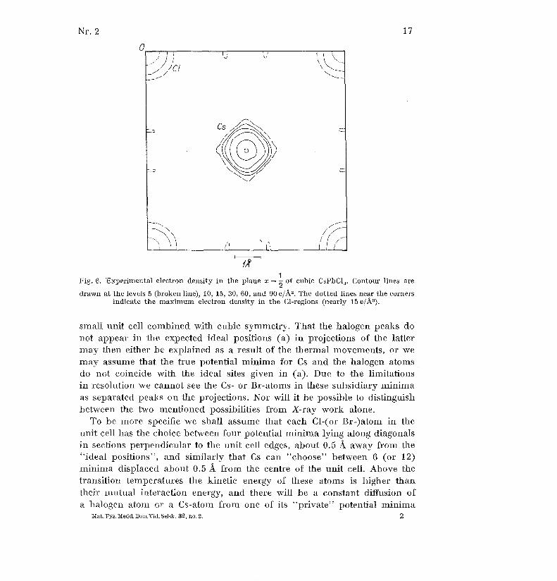
Fig . 6 . Experimental electron density in the plane x = 1 of cubic CsPbCl 3 . Contour lines are
drawn at the levels 5 (broken line), 10, 15, 30, 60, and 90 elk' . The dotted lines near the corner sindicate the maximum electron density in the Cl-regions (nearly 15 e/Ås) .
small unit cell combined with cubic symmetry . That the halogen peaks d onot appear in the expected ideal positions (a) in projections of the latter
may then either be explained as a result of the thermal movements, or w e
may assume that the true potential minima for Cs and the halogen atom sdo not coincide with the ideal sites given in (a) . Due to the limitations
in resolution we cannot see the Cs- or Br-atoms in these subsidiary minim aas separated peaks on the projections . Nor will it be possible to distinguish
between the two mentioned possibilities from X-ray work alone .
To be more specific we shall assume that each Cl-(or Br-)atom in th e
unit cell has the choice between four potential minima lying along diagonal sin sections perpendicular to the unit cell edges, about 0 .5 Å away from the
"ideal positions", and similarly that Cs can "choose" between 6 (or 12)minima displaced about 0 .5 Å from the centre of the unit cell . Above thetransition temperatures the kinetic energy of these atoms is higher tha n
their mutual interaction energy, and there will be a constant diffusion o f
a halogen atom or a Cs-atom from one of its "private" potential minim aMat . Fys . Medd . Dan .V id . Se1sk . 82, no . 2 .
2
18 Nr. 2
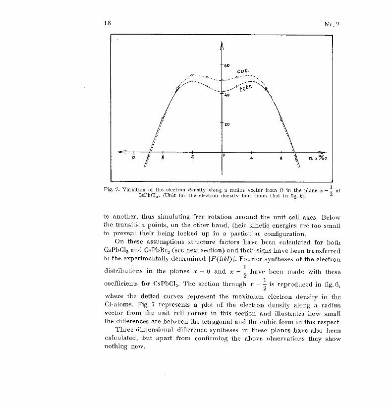
Fig . 7 . Variation of the electron density along a radius vector from O in the plane x = 2 o fCsPbCI 3 . (Unit for the electron density four times that in fig . 6) .
coefficients for CsPbC1 3. The section through x = - is reproduced in fig . 6 ,
where the dotted curves represent the maximum electron density in th eCl-atoms . Fig. 7 represents a plot of the electron density along a radiu svector from the unit cell corner in this section and illustrates how smal lthe differences are between the tetragonal and the cubic form in this respect .
Three-dimensional difference syntheses in these planes have also bee ncalculated, but apart from confirming the above observations they sho wnothing new .
to another, thus simulating free rotation around the unit cell axes . Belowthe transition points, on the other hand, their kinetic energies are too smal lto prevent their being locked up in a particular configuration .
On these assumptions structure factors have been calculated for bothCsPbC 13 and CsPbB r 3 (see next section) and their signs have been transferredto the experimentally determined IF(hk1)I . Fourier syntheses of the electron
distributions in the planes x = 0 and x - 2 have been made with these

Nr. 2
1 9
Comparison of calculated and observed structure factors
Further evidence that the assumption of random distribution of the Cs -
and the halogen atoms on certain selected sites is compatible with the X-ra y
work comes from a comparison of calculated and observed structure factors .These calculations have been made on the basis of the formula
F (hkl) = fi (hkl) • cos 2 Tc (hxi + kgi + lz i ), (5)
where xi , Ui, zi are the atomic parameters, fi the atomic scattering factors ,
and the summation is over all the atoms "i" in the unit cell . The fi (hkl )have been obtained for the different reflections hkl by a graphical method
and this may give rise to small errors of the order of a few per cent of theF(hkl), which, however, is small as compared with the experimental un -
certainty .
Nearly all the structure factors corresponding to reflections within th elimiting sphere for Cuba-radiation have been calculated for both CsPbC1 3and CsPbBr 3 with the atoms in the " ideal positions" (a) and isotropic
atomic scattering factors, i . e . f(hkl) = NO) . It is evident from Tables 3 an d
4 that the structure factors calculated in this way are not in very good agree -
ment with the experimental ones and in several places there are real dis-crepancies . The differences between weak and strong reflections are muc h
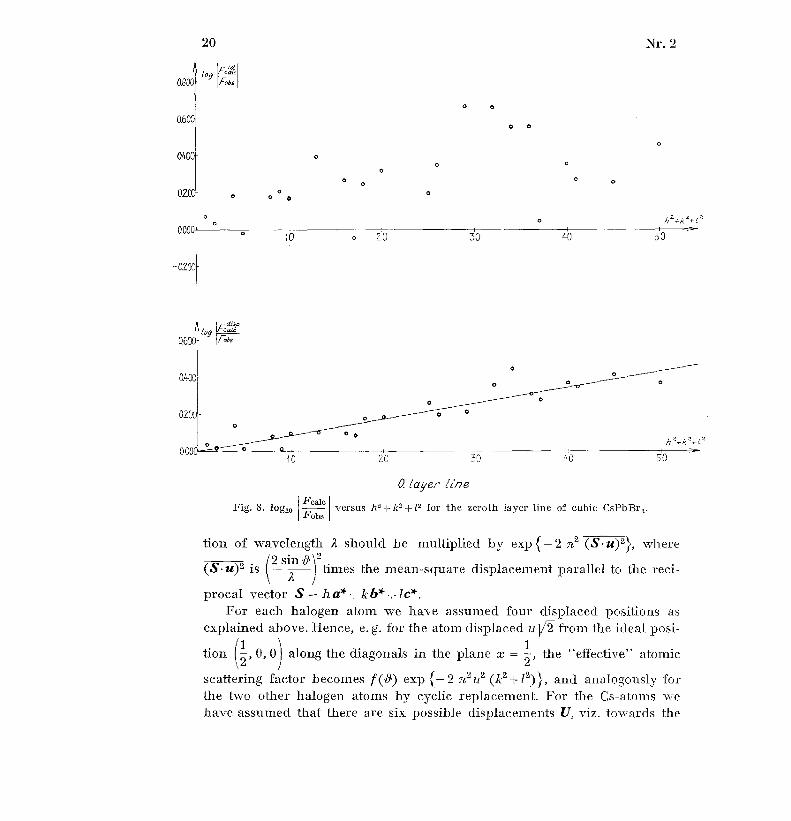
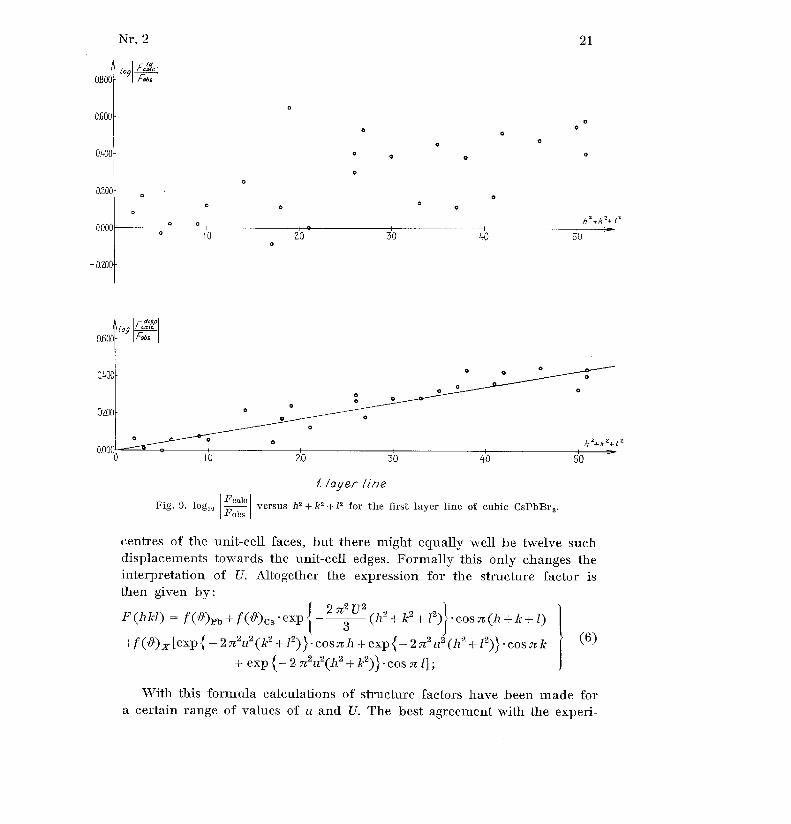
Fcale .less accentuated in the latter than in the former . Plots of log I againstFobs .
h 2 + k2 + 12 should theoretically approach a straight line,' but this is no tvery obvious as seen from the example of CsPbßr3 in figs. 8 and 9 .
Next we have calculated the structure factors on the assumption tha tthe Cs- and halogen atoms are randomly displaced from their ideal posi-
tions. For the X-ray analysis it makes no difference whether the smal l
displacements of the atoms are of a stationary character or whether they
are caused by thermal vibrations of the lattice . This allows the two possibili-
ties to be treated exactly alike and we can take over the whole treatmentof the influence of thermal vibrations on the X-ray intensities . 2
The result of these considerations is that if the displacement amplitud efor the atoms of species "i" is given by the vector u = u x a + u J b + u, c, their
atomic scattering factor appropriate for the reflection hkl with X-ray radia -
' See e .g . H . LIPSON and W . COCHRAN, Determination of Crystal Structures, p . 61 . Lon-don 1953.
2 See e.g . B.W . JAMES, The Optical Principles of the Diffraction of X-Bays . Chapters1 and V . London 1948 .
2*
20 Nr . 2
0.8001tog
0.600-
0.400-
0
o
o
o 0
o
°0
o02C
0
0
0
°
0.000'
0 o
h 2 +k z+( '
10
0
70
30
40
50
-0200 -
1 rog °"'0.6Ø
Fobs
0. layer prieFcalc
versus hz + Iz 2 + 1 2 for the zeroth Iayer line of cubic GsPbßr 3 .Fobs
-Lion of wavelength A should be multiplied by exp { - 2 n 2 (S • u)2 }, where~1 2
(S•u) 2 is
sin
A
I times the mean-square displacement parallel to the reci -
procal vector S = ha*+kb*+lc* .For each halogen atom we have assumed four displaced positions a s
explained above. Hence, e . g . for the atom displaced u V2 from the ideal posi-
tion (2- , 0, 0) along the diagonals in the plane x = 2, the "effective" atomic
scattering factor becomes f (~) exp {- 2 :72 u 2 (k2 + 1 2)), and analogously for
the two other halogen atoms by cyclic replacement. For the Cs-atoms wehave assumed that there are six possible displacements U, viz . towards th e
Fig . 8 . log10
Nr. 2 2 1
(O9 F å°A-;sa
0
0.600 o0
00
0
0 .400 o
G02001-
o
o
o
G
1 00.000
o
o
o
{o2 0
O
0
30
40 5 0
-0200
7 layer lineFcalc
versus 10 Ir + IQ for the first layer line of cubic CsPbBr 3 .Fobs
centres of the unit-cell faces, but there might equally well be twelve suc hdisplacements towards the unit-cell edges . Formally this only changes th einterpretation of U. Altogether the expression for the structure factor i sthen given by :
F(hlcl) = f (~)p b + f(D')c s •exp{ _ 2 763 U2 (hz +k2 +1 2) }•cosac(h +k+l)
+f (0)x [exp { - 27c 2 u 2 (k2 + 1 2))•cosach+exp { - 2ac2 u 2 (h 2 +1 2))•cosack } ( 6 )
+ exp {- 2 ac2 u2 (h2 + k 2)) • cos ~ 1] ;
With this formula calculations of structure factors have been made fo ra certain range of values of u and U. The best agreement with the experi -
Fig . 9 . log 10

22
Nr . 2
TABLE 3 . Comparison of observed and calculated F-values for CsPbC1 3 .
(0 ., 1 ., 2., and 3 . layer line)
Indi- CalculatedObserved F-valuesCubic
structureTetragonalstructureces F-values
Ideal s- Fab s Fobs . Fat
s. Fobs .h k 1perov- Placed temp . about temp.
skiteperov-
skite
ab t54° Co. . corr . 20° C corr .
010 38 37 37 37 36 3 6020 148 133 117 117 118 11 8030 29 29 34 35 33 3 4040 112 83 77 84 81 8 6050 23
27 25 29 24
i 26060 89
55 46 56 49 5 7070 18
27 24 31 26
, 32110 103
100 91 91 89 89120 32
38 38 38 39 40130 85
74 65 68 67 7 0140 26 40 42 46 39 4 2150 66 49 53 62 48 5 3160 20 40 35 42 33 3 9170 56 35 28 37 33 4 1220 130 107 93 96 94
i 9 7230 27 32 31 33 31 3 2240 104 72 62 69 61 6 7250 22 29 25 30 21 2 3260 86 50 39 49 42 4 9330 74 61 49 54 53 5 7340 22 35 28 32 33 3 7350 62 46 37 44 42 4 8360 19 36 25 32 25 3 0440 92 54 39 47 44 5 0450 19 32 25 32 29 34550 56 40 34 44 39 4 8
011 103 100 91 91 89 8 9021 32 38 40 41 36 3 7031 86 75 72 73 74 7 5041 26 40 43 47 41 4 4051 66 49 49 1
57 51 5 6061 20 39 39 147 42 49071 56 35 31 1
41 37 4 6111 T8
Î- -
121 93 91 77 79 70 72131 17 16 - - - -141 74 70 66 73 68 7 3151 8 2 5161 60 52 43 52 46 5 4171 7 28 - -221 29 38 40 42 34 3 5231 79 69 61 66 63 6 6241 24 38 33 37 34 3 7251 64 48 43 50 45 5 1260 19 38 26 33 31 3 6331 $ 25 - - - -341 66 56 46
54 51 5 6351 8 30 -361 57
44 36
46 34 41
Indi- CalculatedObserved F-value s
Tetragonalstructur eces F-values Cubic
structur e
Ideal s -pD Fobs Fobs .Fats
Fous .h k 1 perov- laced temp . temp .
skitepero vskite
about54°C . corr . about
20° G . corr .
441 20 35 25 30 29 33451 58 43 34 43 37 44551 7 32 24 31 24 2 9
012 32 38 32 33 33 3 4022 130 108 96 100 92 9 5032 27 32 33 36 36 3 8042 104 72 69 77
70 7 5052 22 29 28 33
28 3 2062 86 50 41 51
45 5 3112 93 91 81 83
84 8 6122 29 38 39 40
41 42132 79 69 64 69 66 69142 24 38 38 42 39 4 2152 64 47 41 48 44 5 0162 19 37 30 37 31 3 6222 119 91 85 90 80 8 5232 25 34 33 36 30 32242 99 64 54 62 58 6 4252 21 31 25 30 28 3 2262 84 47 38 47 40 4 8332 70 57 48 54 50 5 4342 22 35 29 34 29 3 3352 60 44 34 42 41 4 7362 18 34 25 33 28 34442 89 50 39 48 38 44452 18 32 28 36 28 3 3
013 85 74 57 60 60 6 3023 27 32 34 37 34 3 6033 74 61 60 65 63 6 8043 23 35 34 39 35 3 9053 61 45 37 44 35 4 1063 19 36 29 37 31 37113 10 16 18 19 22 23123 79 69 61 66 62 6 6133 8 25 27 30 29 3 1143 66 57 53 61 52 5 8153 8 29 26 32 26 3 0163 57 44 35 45 38 4 6223 25 33 34 37 33 36233 70 57 49 55 48 5 2243 22 35 30 35 32 3 7253 60 44 34 42 39 4 5263 18 34 25 33 28 3 4333 8 29 25 28 26 2 9343 61 49 39 46 40 4 6353 $
31 25 32 24 2 9443 19
34 28 35 26 3 1453 56
40 33 43 35
p
43

Nr .2
2 3
TABLE 4. Comparison of observed and calculated F-values for CsPbBr 3 .
(0 . and 1 . layer line )
Observed F-values
Cubic
Monoclini cstructure structure
hlclIdeal
perov -
Dis -placed
Fobs ,at
aboutFobstemp .
F ob s
at Fobs .temp .
skiteperov-
1.40° corr .about
corr .skite 20°C .
C -
010 54 50 46 47 48 4 9020 192 170 126 136 128 13 7030 42 27 26 31 23 2 6040 145 100 79 109 96 124050 33 1 9060 116 65 32 67 47 8 1070 26 2 0110 88 84 81 84 95 9 7120 47 50 49 54 53 5 7130 74 63 50 62 59 6 9140 37 51 41 58 49 6 4150 58 41. 26 44 32 4 7160 28 48 25 53 31 5 4170 49 29 14 (37) 21 4 6220 172 133 110
130 126 142230 39 33 26 34 24 3 0240 137 84 55 83 58 7 9250 31 25 15 28 15 2 3260 112 57 24 55 27 5 1330 65 55 37 53 37 4 8340 33
39 21 36 24 34350 54
4.2 15 30 23 3 8360 27
40 15 38
19 3 7440 120
59 26 50
24 3 9450 26
30 14 32
13 25550 49
39 17 46
18 40
Calculate dF-values
Observed F-value sIndi -
ces Cubic Monoclini cstructure structur e
h k 1Idea l
perov-
Dis-placed
Fobs .at
aboutFobs .temp .
Fobs .at
F obs .temp .
skiteperov-
140 ° corr.about
corr .skite 20°C .
C .
011 86 82 71 74 76 7 8021 47 50 50 55 51 5 5031 74 63 56 68 52 6 0041 37 50 45 64 46 5 9051 58 43 23 39 31 4 5061 28 48 22 46 18 3 2071 49 29 14 3 7111 ~ TT 43 46 46 4 8121 79 86 75 85 79 8 6131 3ff 3141 65 75 50 73 65 8 5151 36 17 11 2 0161 53 59 22 47 40 70171 30 22 8 2 2221 43 48 41 49 50 5 7231 69 65 39 51 55 6 8241 34 46 34 52 46 6 3251 56 43 23 42 38 6 0261 28 43 19 43331 40 16 9 1 3341 58 58 29 50 41 6 0351 34 25 12 24361 50 48 17 44 24 48441 30 39 22 42 49 8 0451 52 43 16 3 8551 30 31 12 3 5
Indi-ees
Calculate dF-values
mental I F(hkl) I is obtained with U = 0.075 and u = 0 .070 ; the latter i salso derived directly from the electron projection of CsPbC1 3. The corres-
ponding displacements in A-units are for CsPbC1 3 : 0 .42 Å and 0 .39 A ; and
for CsPbBr3 0 .43 5 A and 0 .40 5 A, respectively .Fdisp .
Plots of log ~aac . against h 2 + k 2 + 12 now show rather good approxima-Fobs .
fions to straight lines of the type
= logl o A+ B • (h 2 + k2 + 12 ), (7 )log loFe ale .
Fobs .
where A and B are constants which can easily be evaluated from the graphs .
The experimentally determined relative I F(hkl) l-values have then been
brought on absolute scales corresponding to F(000) = 186 for CsPbCl3 and
F(000) = 234 for CsPbBr 3 by multiplication with the factors A . They are
24
Nr . 2
given in Tables 3 and 4 in the 4th and 6th column . The last term in (7 )is due to the isotropic thermal movements of the atoms but also include sthe absorption correction . In order to eliminate its influence on the experi-mental F(hkl) they have finally been multiplied by the factor 10Be,liThis final version of the observed structure factors, which is reproduce din Columns 5 and 7 of Table 3 and 4 shows almost perfect agreementwith the structure factors calculated from (6), thus proving our assumption sto be appropriate .
Similar conversions and corrections have been applied to the structur efactors measured for the tetragonal or monoclinic form of these crystals an dthe constants, Btetr . have also been determined . As pointed out above, th eintensities here are more difficult to measure, and hence there is a greateruncertainty on the Fexp . However, the Btetr .-values determined for differentlayer lines of the same crystal at constant temperature are identical withi nthe accuracy of the measurements .
Although the B-values do include a term contributed form the absorp-tion, the differences Btetr .-Boob . by our method of comparing the inten-sities depend only on the temperatures and the possible changes of th eatomic arrangement . If we could be sure that only the changes in therma lmovements of the atoms were of importance the following relation shoul dbe approximately true : '
4B = 0.4343 • 3h21v 1
.4T,2k O, Ya 2
where OD is the "characteristic" or Debye-temperature . Inserting h = 6.62310_ 27
k = 1 .380 10-16 , N = 6.025 -10 23 , and rearranging we get with a, th eunit-cell edge, in Å units :
OD= 35 .32 -1(1 .A Tly
a 1V1 4 B)
In this formula M is the molecular weight of the vibrating particle ; in ou rcase we may presumably insert the molecular weight of the unit-cell con -tents, i .e. CsPbX 3 , thus asking for a lower limit of OD and consideringthe influence of the acoustic waves only .
Neglecting the existence of the superstructure we can then calculat ethe OD compatible with the decrease in intensity of the X-ray reflections
1 Cf . R.W . JAMES, loc . Cit . p . 219-38 .
(8)
(9)
Nr . 2
25
on heating the crystals from room temperature to above their transitio npoints, the results being
OD = 72°K for CsPbCl 3 and O D = 60°K for CsPbBr 3 .
As the characteristic temperatures obtained in this way do not see munreasonable these calculations indicate that very little happens to theatoms at the transition from cubic to tetragonal structure apart from thei rpreferred occupation of one particular set of their possible potential minima .
On the same assumption we may also estimate an average value for th eroot-mean-square displacements of the atoms, due to thermal movements ,from the approximate formula :
-z
a 3
4BT
u
n (10)0 .8686 4 T
We find for CsPbCl3 I 0 ft 0 .25 A, and for CsPbBr 3 j/u2 0 .28 A - valueswhich seem quite reasonable .
Discussion
One of the aims of the present investigations was to determine theconfiguration of the lead-halogen complexes, and at first sight it seemed tha ta very good argument could be given for the regular octahedron from th eexistence of perovskite-like structures with one molecule CsPbX 3 in theunit cell . However, the X-ray analysis shows that this cannot be true, an dif we accept the interpretation given above, it seems doubtful whether itis at all possible to speak of a fixed configuration of a particular PbX G -unit ,- or indeed of such units, in the cubic crystals .
In the tetragonal crystals, on the other hand, it appears that there i sa fixed configuration, but this is not that of a regular octahedron althoug hit is closely related to it . It is interesting that distorted PbX6-octahedra ar ealso found in the yellow, orthorhombic CsPbI3 and in the compoundsCs 4 PbXe, . '
Although the displacements of the atoms from their ideal positions i nthe cubic crystals could have been described in terms of thermal movement swe have here preferred to assume the existence of several possible potentia lminima for the Cs and X-toms, because the vibrational amplitudes in th e
C .K . MIØLLER . To be published in this series .
26 Nr . 2
former description become rather large . Nor can we exclude the possibi-lity of free rotations of these atoms in the cubic crystals, but wheneve rthis has been assumed to explain certain transition phenomena in crystals ,it has been shown that they may equally well, if not better, be explaine dby order-disorder transformations)
It is tried to get a decision of this question from measurement of the ,entropy change at the transformation (CsPbC13)tetr .
( CsPbC13)eub . .On the above assumption there cannot be one single characteristic Cs- X
distance in the cubic crystals, but rather a certain range of discrete values .The Pb-X distances on the other hand are well-defined, but they are con-siderably shorter than the distances to be expected from the sum of ioni cradii . 2 (See Table 5) .
This has also been observed for other crystals which contain lead an dhalogen atoms, and it may mean either that the ionic radius for Pb needs arevision or (more likely) that polarization ( "coval.ency") is of importanc ein these compounds . The colour of the crystals also strongly suggests th elatter explanation .
On the whole the perovskite-like crystals of the type CsPbX 3 show somany analogies to the crystals of mixed oxides of the BaTiO 3 -type that i tis tempting to apply also to the latter the interpretation given here of th etransformation from tetragonal to cubic structure . In this way there wouldbe a close analogy of dielectric phenomena in solids to those in gases :The situation at temperatures above the transition to cubic structure wher e"free" diffusion of anions and some cations among selected potential minim acreates a structure with maximum disorder of the kind described above,corresponds to a polar gas at very high temperatures in a very weak electri cfield (no orientation) . Below the transition temperature the preferred occupa-tion of certain potential minima (also present in the cubic state) may resultin a multiple cell with no dipole moment, in which case we have an anti-ferroelectric phase. This corresponds to a non-polar gas of associated dipola rmolecules (internal compensation) . - Or the result of the transformatio nmay be a unit cell with a dipole moment, whose electric field will hel pto create a preferred configuration all through the crystal, thus giving aferroelectric . The analogy here, of course, is a gas of polar molecules i nan electric field and at not too high temperatures .
Based on ideas of this kind MASON and MATT1-nAs 3 have developed aJ. FRENKEL, Kinetic Theory of Liquids . Chapter II. Oxford 1948 . See also J . P . MATHIEU ,
Yearbook . Phys . Soc. G.B., 23-29 (1956) .2 LANDOLT-BÖRNSTEIN, I . Band, 4. Teil p . 523 .2 w. P. MASON and B . T . MATHIAS, Phys. Rev. 74, 1622 (1948) .

Nr.2 27
TABLE 5 . Some interatomic distances in the perovskite-like
crystals of CsPbCl3 and CsPbBr3
Pb -X CS- Xmax. Cs - Xprob . CS-X min .
From the present work 2 .86 å 3 .76 Å 3 .68 Å 3 .13 ACsPbC1 3 From Pauling's ionic radii 3 .02 - 3 .50 -
From Goldschmidt's ionic radii 3 .13 - 3 .48 -
From the present work 2 .99 - 3.94 - 3 .85 -- 3 .28 -CsPbßr 3 jll From Pauling's ionic radii 3 .16 - 3 .64 -
From Goldschmidt's ionic radii . . 3 .28 - 3 .63 -
theory for ferroelectricity in BaTiO 3 which, however, has been severel ycriticized by JAYNES ' mainly for the following reason . An order-disordertransition involving 6 close-lying Ti-positions (as assumed by MASON andMATTIIIAS) will require an entropy change R log 6 3 .6 cal mol-ldeg ',
but the measured value is only about 0 .1 cal mol-' deg-1 . However, it doe snot seem quite obvious how the entropy measurements should be inter-
preted, nor whether the simple calculation of the entropy is strictly valid .It is hoped that measurement of the corresponding entropy change i nCsPhC 13 may help to clarify some of these problems, and it is also suggeste dthat it might be interesting to make a thorough neutron or X-ray investiga-tion of BaTiO 3 at temperatures above 120°C .
Acknowledgements
I wish to thank Professor A. TOVBORG JENSEN, Ph. D., for his interes tin this work and Mr . PETER COLDING JØRGENSEN for carrying out man yof the calculations and measurements .
For a survey and references see H .D . MEGA, Ferroelectricity in crystals, Chapter 10 .Methuen, London 1957 .
indleveret til selskabet den 11. juni 1959 .
Færdig fra trykkeriet den 31 . december 1959 .