
The Simultaneous Modeling Technique: closing gaps in ...
24
58 THE INTERNATIONAL JOURNAL OF ESTHETIC DENTISTRY CLINICAL RESEARCH Correspondence to: Gaetano Paolone, DDS Viale dei Quattro Venti, 233, 00152 Rome, Italy; Email: [email protected] The Simultaneous Modeling Technique: closing gaps in posteriors Salvatore Scolavino, DDS Private Practice, Nola, Naples, Italy Gaetano Paolone, DDS Private practice, Rome, Italy Adjunct Professor, Restorative Dentistry, Dental School, Vita-Salute San Raffaele University, Milan, Italy Giovanna Orsini, DDS, PhD Associate Professor, Restorative Dentistry, School of Dentistry, Polytechnic University of Marche, Ancona, Italy Walter Devoto, DDS Private and Referral Practice, Sestri Levante, Italy Lecturer, Master of Endodontics and Restorative Dentistry, University of Siena, Italy Visiting Professor, University of Marseille, France, and International University of Catalonia, Barcelona, Spain Angelo Putignano, MD, DDS Professor, Restorative Dentistry, Head of Department of Endodontics and Operative Dentistry, School of Dentistry, Polytechnic University of Marche, Ancona, Italy
Transcript of The Simultaneous Modeling Technique: closing gaps in ...
58THE INTERNATIONAL JOURNAL OF ESTHETIC DENTISTRY
CLINICAL RESEARCH
Correspondence to: Gaetano Paolone, DDS
Viale dei Quattro Venti, 233, 00152 Rome, Italy; Email: [email protected]
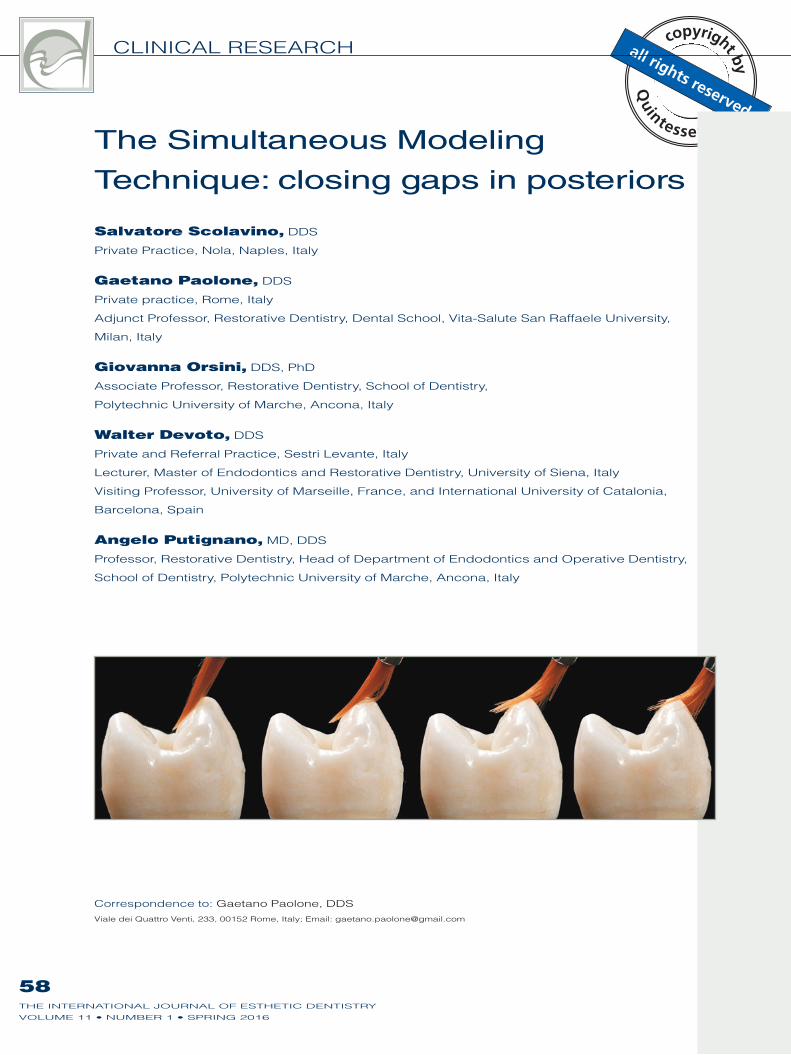
The Simultaneous Modeling
Technique: closing gaps in posteriors
Salvatore Scolavino, DDS
Private Practice, Nola, Naples, Italy
Gaetano Paolone, DDS
Private practice, Rome, Italy
Adjunct Professor, Restorative Dentistry, Dental School, Vita-Salute San Raffaele University,
Milan, Italy
Giovanna Orsini, DDS, PhD
Associate Professor, Restorative Dentistry, School of Dentistry,
Polytechnic University of Marche, Ancona, Italy
Walter Devoto, DDS
Private and Referral Practice, Sestri Levante, Italy
Lecturer, Master of Endodontics and Restorative Dentistry, University of Siena, Italy
Visiting Professor, University of Marseille, France, and International University of Catalonia,
Barcelona, Spain
Angelo Putignano, MD, DDS
Professor, Restorative Dentistry, Head of Department of Endodontics and Operative Dentistry,
School of Dentistry, Polytechnic University of Marche, Ancona, Italy
59THE INTERNATIONAL JOURNAL OF ESTHETIC DENTISTRY
SCOLAVINO ET AL
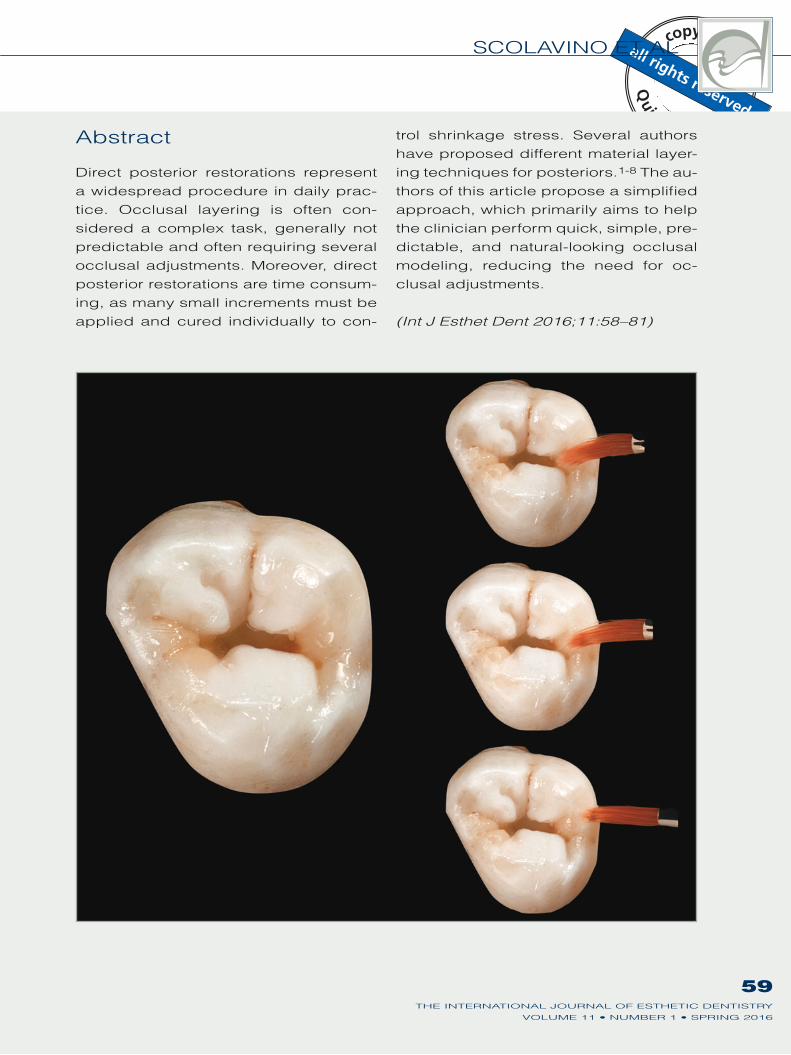
Abstract
Direct posterior restorations represent
a widespread procedure in daily prac-
tice. Occlusal layering is often con-
sidered a complex task, generally not
predictable and often requiring several
occlusal adjustments. Moreover, direct
posterior restorations are time consum-
ing, as many small increments must be
applied and cured individually to con-
trol shrinkage stress. Several authors
have proposed different material layer-
ing techniques for posteriors.1-8 The au-
thors of this article propose a simplified
approach, which primarily aims to help
the clinician perform quick, simple, pre-
dictable, and natural-looking occlusal
modeling, reducing the need for oc-
clusal adjustments.
(Int J Esthet Dent 2016;11:58–81)
59THE INTERNATIONAL JOURNAL OF ESTHETIC DENTISTRY
60THE INTERNATIONAL JOURNAL OF ESTHETIC DENTISTRY
CLINICAL RESEARCH
Introduction
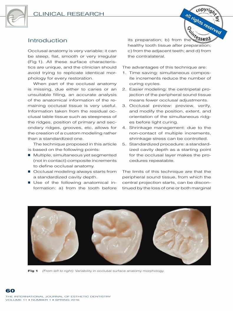
Occlusal anatomy is very variable; it can
be steep, flat, smooth or very irregular
(Fig 1). All these surface characteris-
tics are unique, and the clinician should
avoid trying to replicate identical mor-
phology for every restoration.
When part of the occlusal anatomy
is missing, due either to caries or an
unsuitable filling, an accurate analysis
of the anatomical information of the re-
maining occlusal tissue is very useful.
Information taken from the residual oc-
clusal table tissue such as steepness of
the ridges, position of primary and sec-
ondary ridges, grooves, etc, allows for
the creation of a custom modeling rather
than a standardized one.
The technique proposed in this article
is based on the following points:
Multiple, simultaneous yet segmented
(not in contact) composite increments
to define occlusal anatomy.
Occlusal modeling always starts from
a standardized cavity depth.
Use of the following anatomical in-
formation: a) from the tooth before
its preparation; b) from the residual
healthy tooth tissue after preparation;
c) from the adjacent teeth; and d) from
the contralateral.
The advantages of this technique are:
1. Time saving: simultaneous compos-
ite increments reduce the number of
curing cycles.
2. Easier modeling: the centripetal pro-
jection of the peripheral sound tissue
means fewer occlusal adjustments.
3. Occlusal preview: preview, verify,
and modify the position, extent, and
orientation of the simultaneous ridg-
es before light curing.
4. Shrinkage management: due to the
non-contact of multiple increments,
shrinkage stress can be controlled.
5. Standardized procedure: a standard-
ized cavity depth as a starting point
for the occlusal layer makes the pro-
cedures repeatable.
The limits of this technique are that the
peripheral sound tissue, from which the
central projection starts, can be discon-
tinued by the loss of one or both marginal
Fig 1 (From left to right): Variability in occlusal surface anatomy morphology.
61THE INTERNATIONAL JOURNAL OF ESTHETIC DENTISTRY
SCOLAVINO ET AL
ridges, or one or more cusps. Clinicians
can face two different situations with two
different outcomes:
1. Marginal ridges: these can be re-
stored in a predictable way using
proven techniques.9
2. Cusps: freehand modeling of a cusp
(height, thickness, and tip position) is
difficult, arbitrary, and unpredictable,
mainly due to the lack of references.
Due to rubber dam isolation, it is im-
possible to verify the interocclusal
relationship. Indirect restorations can
provide a more practical and predict-
able solution for the clinician in these
situations.
Description of the
technique
Knowledge of dental anatomy is cru-
cial. Although this technique presents a
workflow that allows for simplified mod-
eling in posteriors, the main aspects
of occlusal anatomy and their possible
variability should be known for every
tooth, including the average position of
grooves, pits, ridges, triangular ridges,
oblique ridges, and marginal ridges, as
well as the size ratio of ridges.
Observation
The preliminary stage of gathering in-
formation should be performed prior to
rubber dam isolation.
Analysis of the teeth to be treatedObservation plays a very important role
in the initial stage. If the teeth to be treat-
ed are not already destroyed or do not
contain incongruous extensive restor-
ations, the analysis of these teeth allows
the clinician to define the position of the
grooves and pits, as well as the orienta-
tion and steepness of the crestal slopes.
Analysis of the adjacent teethThe depth of the grooves, the inclina-
tion of the crestal slopes, and the height
of the marginal ridges (in the case of
class II) can be quickly detected from
the neighboring teeth.
Cavity requirements
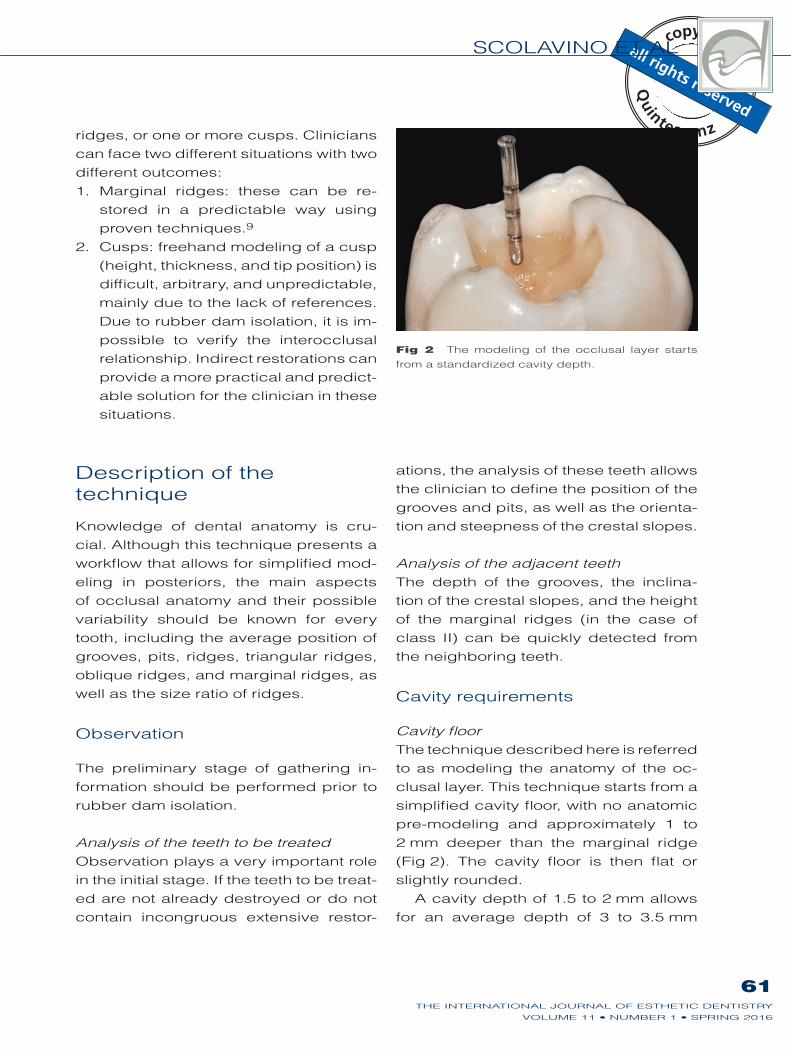
Cavity floorThe technique described here is referred
to as modeling the anatomy of the oc-
clusal layer. This technique starts from a
simplified cavity floor, with no anatomic
pre-modeling and approximately 1 to
2 mm deeper than the marginal ridge
(Fig 2). The cavity floor is then flat or
slightly rounded.
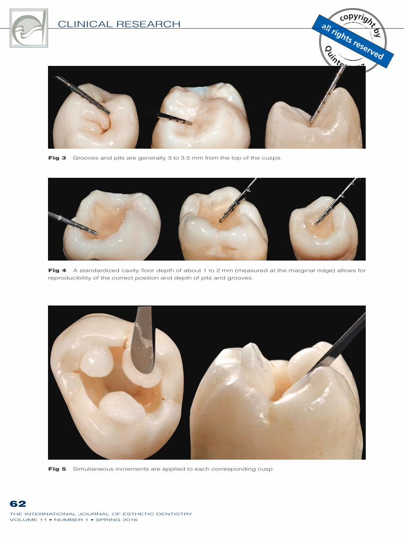
A cavity depth of 1.5 to 2 mm allows
for an average depth of 3 to 3.5 mm
Fig 2 The modeling of the occlusal layer starts
from a standardized cavity depth.
CLINICAL RESEARCH
62THE INTERNATIONAL JOURNAL OF ESTHETIC DENTISTRY
Fig 3 Grooves and pits are generally 3 to 3.5 mm from the top of the cusps.
Fig 4 A standardized cavity floor depth of about 1 to 2 mm (measured at the marginal ridge) allows for
reproducibility of the correct position and depth of pits and grooves.
Fig 5 Simultaneous increments are applied to each corresponding cusp.
SCOLAVINO ET AL
63THE INTERNATIONAL JOURNAL OF ESTHETIC DENTISTRY
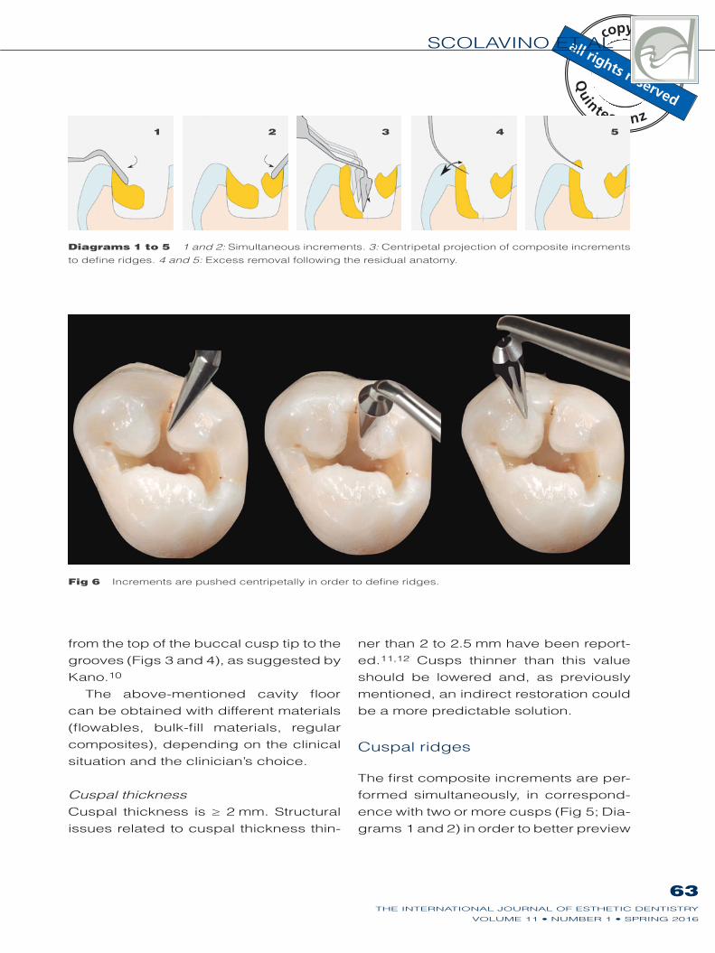
Fig 6 Increments are pushed centripetally in order to define ridges.
Diagrams 1 to 5 1 and 2: Simultaneous increments. 3: Centripetal projection of composite increments
to define ridges. 4 and 5: Excess removal following the residual anatomy.
from the top of the buccal cusp tip to the
grooves (Figs 3 and 4), as suggested by
Kano.10
The above-mentioned cavity floor
can be obtained with different materials
(flowables, bulk-fill materials, regular
composites), depending on the clinical
situation and the clinician’s choice.
Cuspal thicknessCuspal thickness is ≥ 2 mm. Structural
issues related to cuspal thickness thin-
ner than 2 to 2.5 mm have been report-
ed.11,12 Cusps thinner than this value
should be lowered and, as previously
mentioned, an indirect restoration could
be a more predictable solution.
Cuspal ridges
The first composite increments are per-
formed simultaneously, in correspond-
ence with two or more cusps (Fig 5; Dia-
grams 1 and 2) in order to better preview
1 2 3 4 5
CLINICAL RESEARCH
64THE INTERNATIONAL JOURNAL OF ESTHETIC DENTISTRY
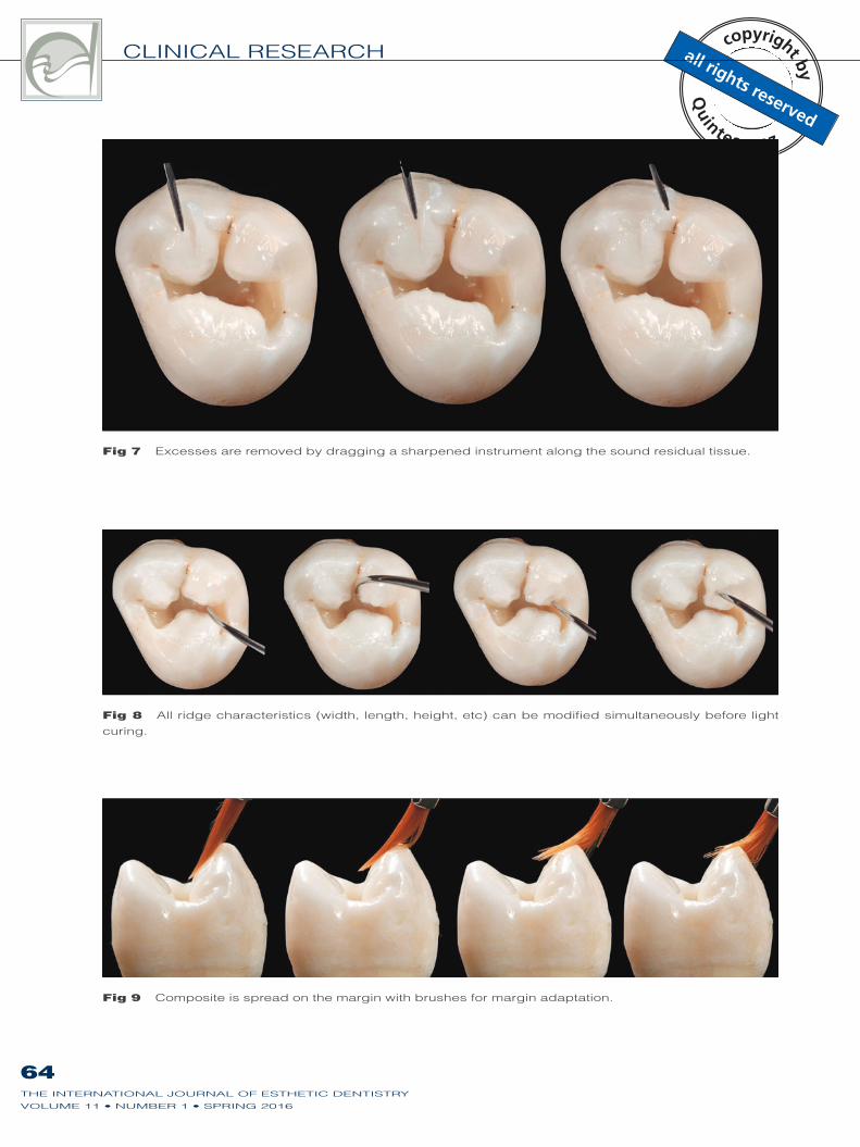
Fig 8 All ridge characteristics (width, length, height, etc) can be modified simultaneously before light
curing.
Fig 9 Composite is spread on the margin with brushes for margin adaptation.
Fig 7 Excesses are removed by dragging a sharpened instrument along the sound residual tissue.
SCOLAVINO ET AL
65THE INTERNATIONAL JOURNAL OF ESTHETIC DENTISTRY
cuspal relationships. Composite is then
squeezed and pushed toward the cent-
the ridge bodies (Diagram 3). To con-
trol shrinkage stress, ridge extensions
should not be in contact with each other.
The occlusal table will be closed in the
final step, allowing further anatomy ad-
justments. Any excess composite can
be removed by dragging along a sharp-
ened instrument parallel7 to the sound
residual tissue (Fig 7; Diagrams 4 and
5). Final ridge adjustments are done be-
fore light curing (Fig 8). Margin adapta-
tion is achieved by spreading compos-
ite on the margin with a brush (Fig 9;
Diagrams 5 to 7).
In this step, we define the anatomic
sketch that outlines:
1. Main ridge orientation, location, and
volume.
2. Approximate path of the primary
and secondary grooves.
3. Approximate position of the main pits.
In this step, the clinician can check
and correct length, orientation, and
ridge volumes before light curing (Dia-
grams 8 and 9). The first increments can
be slightly undersized, both to manage
shrinkage stress and to allow appropri-
ate corrections with further increments.
Marginal ridges
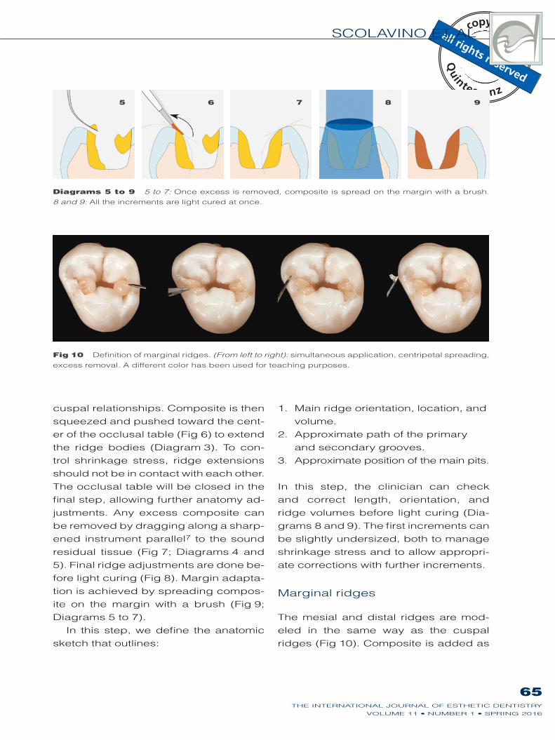
The mesial and distal ridges are mod-
eled in the same way as the cuspal
ridges (Fig 10). Composite is added as
Fig 10 Definition of marginal ridges. (From left to right): simultaneous application, centripetal spreading,
excess removal. A different color has been used for teaching purposes.
Diagrams 5 to 9 5 to 7: Once excess is removed, composite is spread on the margin with a brush.
8 and 9: All the increments are light cured at once.
5 6 7 8 9
CLINICAL RESEARCH
66THE INTERNATIONAL JOURNAL OF ESTHETIC DENTISTRY
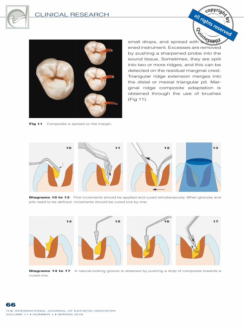
Diagrams 10 to 13 First increments should be applied and cured simultaneously. When grooves and
pits need to be defined, increments should be cured one by one.
Diagrams 14 to 17 A natural-looking groove is obtained by pushing a drop of composite towards a
cured one.
Fig 11 Composite is spread on the margin.
small drops, and spread with a sharp-
ened instrument. Excesses are removed
by pushing a sharpened probe into the
sound tissue. Sometimes, they are split
into two or more ridges, and this can be
detected on the residual marginal crest.
Triangular ridge extension merges into
the distal or mesial triangular pit. Mar-
ginal ridge composite adaptation is
obtained through the use of brushes
(Fig 11).
10 11 12 13
14 15 16 17
SCOLAVINO ET AL
67THE INTERNATIONAL JOURNAL OF ESTHETIC DENTISTRY
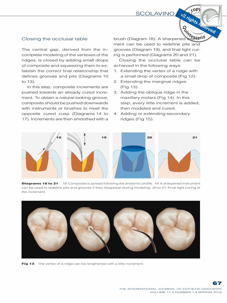
Closing the occlusal table
The central gap, derived from the in-
complete modeling of the vertexes of the
ridges, is closed by adding small drops
of composite and squeezing them to es-
tablish the correct final relationship that
defines grooves and pits (Diagrams 10
to 13).
In this step, composite increments are
pushed towards an already cured incre-
ment. To obtain a natural-looking groove,
composite should be pushed downwards
with instruments or brushes to meet the
opposite cured cusp (Diagrams 14 to
17). Increments are then smoothed with a
brush (Diagram 18). A sharpened instru-
ment can be used to redefine pits and
grooves (Diagram 19), and final light cur-
ing is performed (Diagrams 20 and 21).
Closing the occlusal table can be
achieved in the following ways:
1. Extending the vertex of a ridge with
a small drop of composite (Fig 12).
2. Extending the marginal ridges
(Fig 13).
3. Adding the oblique ridge in the
maxillary molars (Fig 14). In this
step, every little increment is added,
then modeled and cured.
4. Adding or extending secondary
ridges (Fig 15).
Diagrams 18 to 21 18: Composite is spread following the anatomic profile. 19: A sharpened instrument
can be used to redefine pits and grooves if they disappear during modeling. 20 to 21: Final light curing of
the increment.
Fig 12 The vertex of a ridge can be lengthened with a little increment.
18 19 20 21
CLINICAL RESEARCH
68THE INTERNATIONAL JOURNAL OF ESTHETIC DENTISTRY
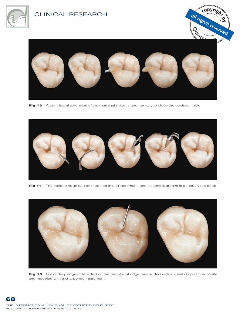
Fig 15 Secondary ridges, detected on the peripheral ridge, are added with a small drop of composite
and modeled with a sharpened instrument.
Fig 13 A centripetal extension of the marginal ridge is another way to close the occlusal table.
Fig 14 The oblique ridge can be modeled in one increment, and its central groove is generally not deep.
SCOLAVINO ET AL
69THE INTERNATIONAL JOURNAL OF ESTHETIC DENTISTRY
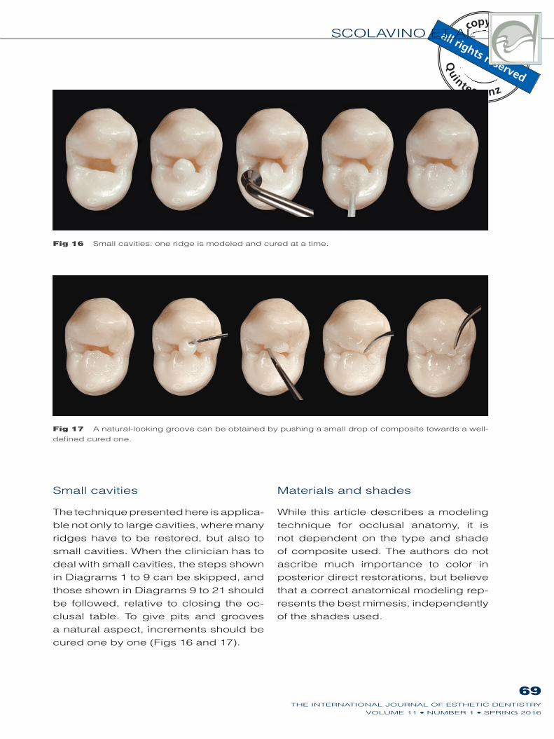
Fig 16 Small cavities: one ridge is modeled and cured at a time.
Fig 17 A natural-looking groove can be obtained by pushing a small drop of composite towards a well-
defined cured one.
Small cavities
The technique presented here is applica-
ble not only to large cavities, where many
ridges have to be restored, but also to
small cavities. When the clinician has to
deal with small cavities, the steps shown
in Diagrams 1 to 9 can be skipped, and
those shown in Diagrams 9 to 21 should
be followed, relative to closing the oc-
clusal table. To give pits and grooves
a natural aspect, increments should be
Materials and shades
While this article describes a modeling
technique for occlusal anatomy, it is
not dependent on the type and shade
of composite used. The authors do not
ascribe much importance to color in
posterior direct restorations, but believe
that a correct anatomical modeling rep-
resents the best mimesis, independently
of the shades used.

CLINICAL RESEARCH
70THE INTERNATIONAL JOURNAL OF ESTHETIC DENTISTRY
Shrinkage in the occlusal layer
Although none of the layering tech-
niques can avoid the effects of poly-
merization shrinkage,13 many studies
have shown that an incremental layer-
ing technique results in better perfor-
mance than does bulk placement.14-17
Shrinkage stress seems to relate more
to the volume of the restoration than to
its ‘C’ factor.18,19
In a multi-layered restoration, if the fi-
nal occlusal increment is cured all at
the same time, it produces the highest
cuspal deflection.20
The shrinkage direction of compos-
ite increments is affected by both the
bonded surfaces and the free ones.21
The simultaneous split incremental pro-
cedure proposed here is based on re-
specting all the above-mentioned issues
aimed to reduce polymerization shrink-
age stress. In particular, among all the
composite ridges, the final connection
(closing the occlusal table) is achieved
with only a little increment that fills the
small residual occlusal gap in the least
stressful way.
Clinical cases
The following clinical cases have been
restored using the technique described
in this article.
Case 1
Fig 18 Fig 19 Isolation. Fig 20 Cavity preparation.
SCOLAVINO ET AL
71THE INTERNATIONAL JOURNAL OF ESTHETIC DENTISTRY
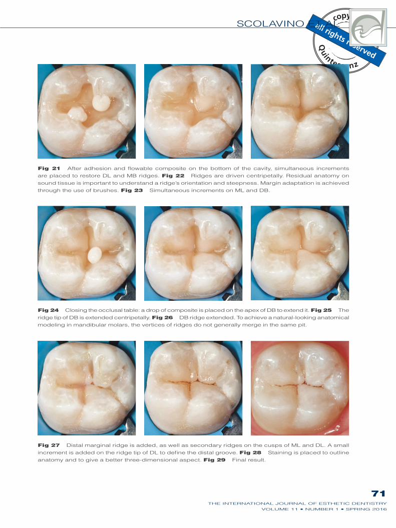
Fig 21 After adhesion and flowable composite on the bottom of the cavity, simultaneous increments
are placed to restore DL and MB ridges. Fig 22 Ridges are driven centripetally. Residual anatomy on
sound tissue is important to understand a ridge’s orientation and steepness. Margin adaptation is achieved
through the use of brushes. Fig 23 Simultaneous increments on ML and DB.
Fig 24 Closing the occlusal table: a drop of composite is placed on the apex of DB to extend it. Fig 25 The
ridge tip of DB is extended centripetally. Fig 26 DB ridge extended. To achieve a natural-looking anatomical
modeling in mandibular molars, the vertices of ridges do not generally merge in the same pit.
Fig 27 Distal marginal ridge is added, as well as secondary ridges on the cusps of ML and DL. A small
increment is added on the ridge tip of DL to define the distal groove. Fig 28 Staining is placed to outline
anatomy and to give a better three-dimensional aspect. Fig 29 Final result.
CLINICAL RESEARCH
72THE INTERNATIONAL JOURNAL OF ESTHETIC DENTISTRY
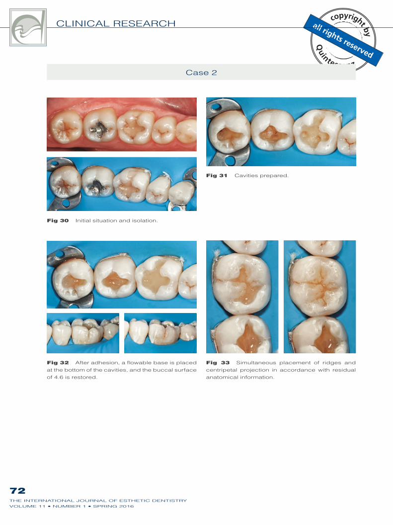
Case 2
Fig 30 Initial situation and isolation.
Fig 31 Cavities prepared.
Fig 32 After adhesion, a flowable base is placed
at the bottom of the cavities, and the buccal surface
Fig 33 Simultaneous placement of ridges and
centripetal projection in accordance with residual
anatomical information.
SCOLAVINO ET AL
73THE INTERNATIONAL JOURNAL OF ESTHETIC DENTISTRY
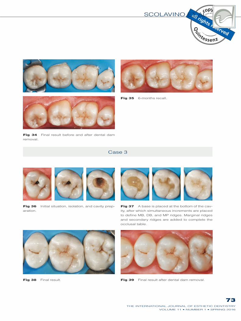
Fig 34 Final result before and after dental dam
removal.
Fig 35
Fig 38 Final result. Fig 39 Final result after dental dam removal.
Case 3
Fig 36 Initial situation, isolation, and cavity prep-
aration.
Fig 37 A base is placed at the bottom of the cav-
ity, after which simultaneous increments are placed
to define MB, DB, and MP ridges. Marginal ridges
and secondary ridges are added to complete the
occlusal table.
CLINICAL RESEARCH
74THE INTERNATIONAL JOURNAL OF ESTHETIC DENTISTRY
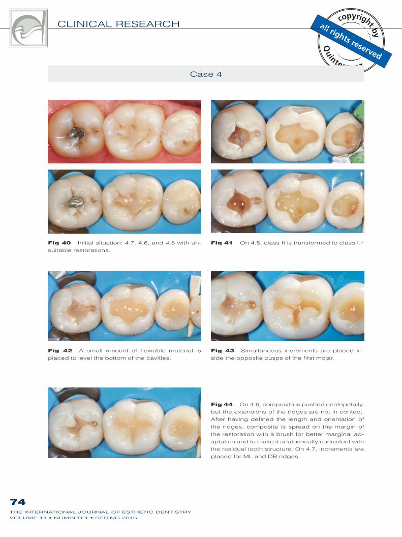
Fig 40 -
suitable restorations.
Fig 41 On 4.5, class II is transformed to class I.9
Fig 42 A small amount of flowable material is
placed to level the bottom of the cavities.
Fig 43 Simultaneous increments are placed in-
side the opposite cusps of the first molar.
Fig 44 but the extensions of the ridges are not in contact.
After having defined the length and orientation of
the ridges, composite is spread on the margin of
the restoration with a brush for better marginal ad-
aptation and to make it anatomically consistent with
the residual tooth structure. On 4.7, increments are
placed for ML and DB ridges.
Case 4
SCOLAVINO ET AL
75THE INTERNATIONAL JOURNAL OF ESTHETIC DENTISTRY
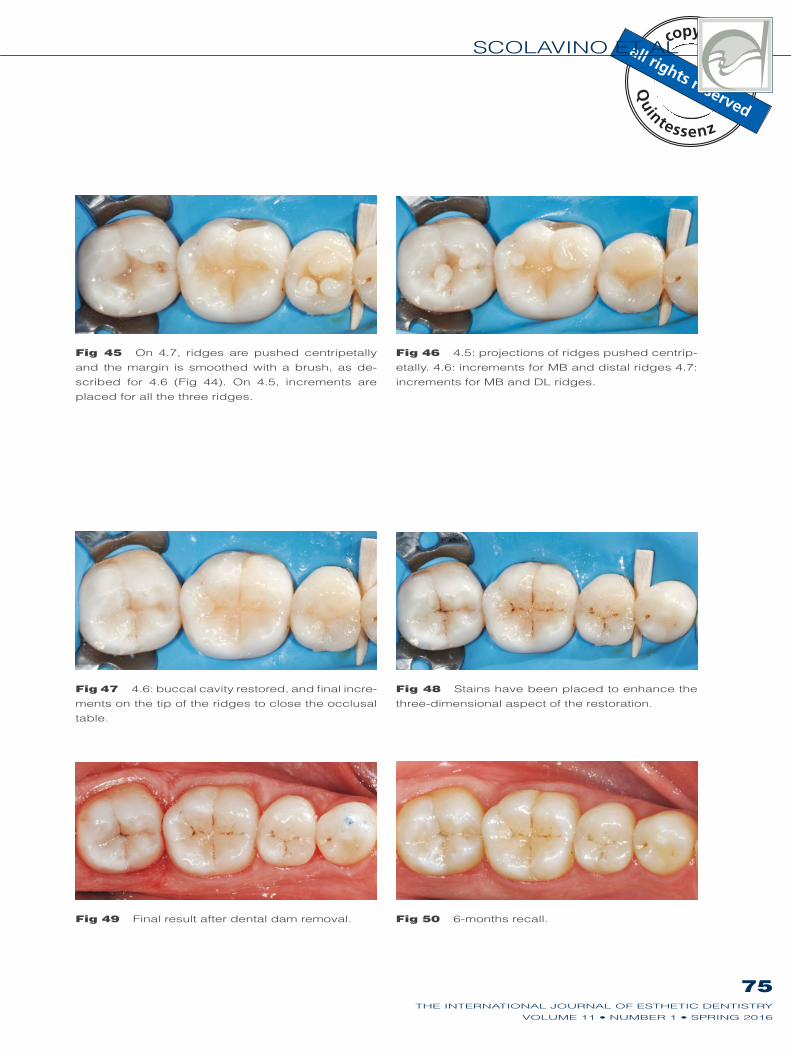
Fig 45 On 4.7, ridges are pushed centripetally
and the margin is smoothed with a brush, as de-
placed for all the three ridges.
Fig 46 4.5: projections of ridges pushed centrip-
increments for MB and DL ridges.
Fig 47 -
ments on the tip of the ridges to close the occlusal
table.
Fig 48 Stains have been placed to enhance the
three-dimensional aspect of the restoration.
Fig 49 Final result after dental dam removal. Fig 50
CLINICAL RESEARCH
76THE INTERNATIONAL JOURNAL OF ESTHETIC DENTISTRY
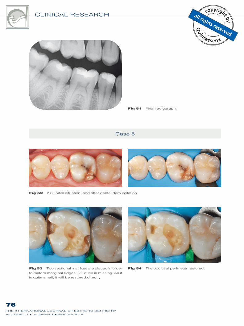
Fig 52
Fig 53 Two sectional matrixes are placed in order
to restore marginal ridges. DP cusp is missing. As it
is quite small, it will be restored directly.
Fig 54 The occlusal perimeter restored.
Case 5
Fig 51 Final radiograph.
SCOLAVINO ET AL
77THE INTERNATIONAL JOURNAL OF ESTHETIC DENTISTRY
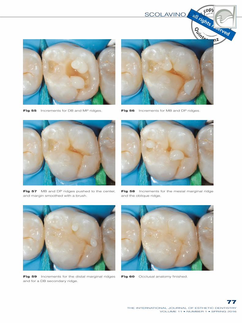
Fig 55 Increments for DB and MP ridges. Fig 56 Increments for MB and DP ridges.
Fig 57 MB and DP ridges pushed to the center,
and margin smoothed with a brush.
Fig 58 Increments for the mesial marginal ridge
and the oblique ridge.
Fig 59 Increments for the distal marginal ridges
and for a DB secondary ridge.
Fig 60 Occlusal anatomy finished.
CLINICAL RESEARCH
78THE INTERNATIONAL JOURNAL OF ESTHETIC DENTISTRY
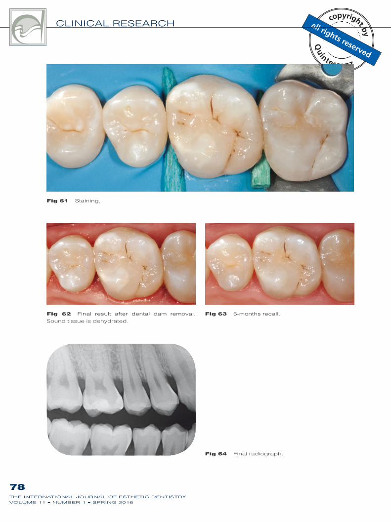
Fig 62 Final result after dental dam removal.
Sound tissue is dehydrated.
Fig 63
Fig 64 Final radiograph.
Fig 61 Staining.
SCOLAVINO ET AL
79THE INTERNATIONAL JOURNAL OF ESTHETIC DENTISTRY
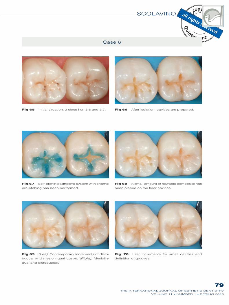
Fig 65 Fig 66 After isolation, cavities are prepared.
Fig 67 Self-etching adhesive system with enamel
pre-etching has been performed.
Fig 68 A small amount of flowable composite has
been placed on the floor cavities.
Fig 69 (Left): Contemporary increments of disto-
buccal and mesiolingual cusps. (Right): Mesiolin-
gual and distobuccal.
Fig 70 Last increments for small cavities and
definition of grooves.
CLINICAL RESEARCH
80THE INTERNATIONAL JOURNAL OF ESTHETIC DENTISTRY
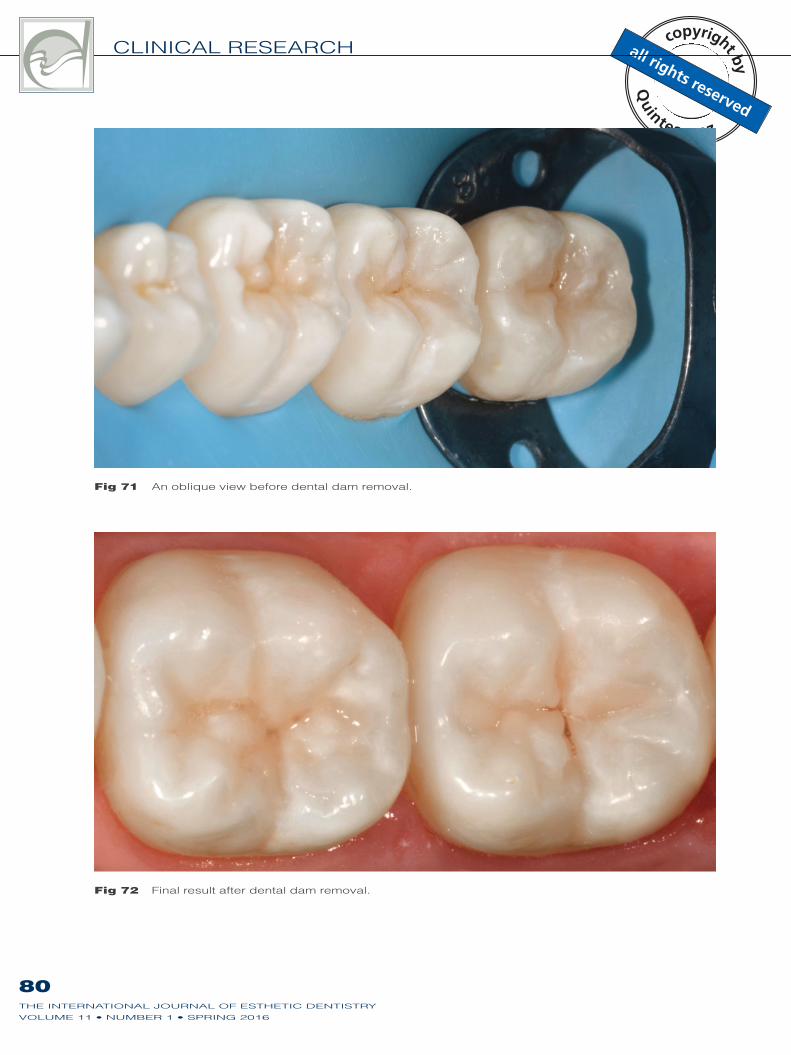
Fig 71 An oblique view before dental dam removal.
Fig 72 Final result after dental dam removal.
81THE INTERNATIONAL JOURNAL OF ESTHETIC DENTISTRY
SCOLAVINO ET AL
Conclusion
Direct posterior restorations are a com-
mon task in daily practice. This article
describes a simplified approach, based
on the simultaneous increments for mod-
eling the occlusal table according to the
peripheral residual anatomy. This helps
clinicians to perform simpler, quicker
restorations that need fewer occlusal
adjustments.
Acknowledgments
The authors would like to thank Dr Gurvinder Bhirth
and Dr Ronan O’Donoghue for their valuable sug-
gestions and their help with proofreading this article.
References
1. Tjan AH, Bergh BH, Lidner
C. Effect of various incre-
mental techniques on the
marginal adaptation of class
II composite restorations. J
2. Deliperi S, Bardwell DN. An
alternative method to reduce
polymerization shrinkage
in direct posterior compos-
ite restorations. J Am Dent
3. Lopes GC, Vieira LC, Araujo
E. Direct composite restor-
ations: a review of some clin-
ical procedures to achieve
predictable results in pos-
terior teeth. J Esthet Restor
-
sion 32.
4. Boer WM. Simple guidelines
for aesthetic success with
restorations. Pract Proced
247;quiz 248.
5. Schlichting LH, Monteiro S Jr,
Baratieri LN. A new proposal
to optimize the occlusal
margin in direct resin com-
posite restorations of poster-
ior teeth. Eur J Esthet Dent
-
tal and stratified layering
techniques to produce an
esthetic posterior composite
restoration with a predictable
prognosis. J Esthet Restor
7. Dietschi D, Spreafico R.
Adhesive metal-free restor-
in the aesthetic treatment of
posterior teeth. Berlin: Quin-
tessence, 1997.
8. Baratieri LN, Monteiro Júnior
S, Correa M, Ritter AV.
Posterior resin composite
restorations: a new tech-
nique. Quintessence Int
9. Bichacho N. The centripetal
build-up for composite resin
posterior restorations. Pract
Periodontics Aesthet Dent
10. Kano P. Challenging Nature:
Wax-up Techniques in Aes-
thetics and Functional Occlu-
sion. Quintessence, 2011.
11. Krifka S, Anthofer T, Fritzsch
M, Hiller KA, Schmalz G,
Federlin M. Ceramic inlays
and partial ceramic crowns:
influence of remaining cusp
wall thickness on the margin-
al integrity and enamel crack
formation in vitro. Oper Dent
12. Fichera G, Re C. Restauri
estetico-adesivi indiretti:
modello per diagnosi di con-
figurazione cavitaria. Den-
13. Loguercio AD, Reis A,
Schroeder M, Balducci I,
Versluis A, Ballester RY.
Polymerization shrinkage:
effects of boundary condi-
tions and filling technique of
resin composite restorations.
14. Wilson EG, Mandradjieff M,
Brindock T. Controversies
in posterior composite resin
restorations. Dent Clin North
15. Soares CJ, Bicalho AA, Tant-
birojn D, Versluis A. Polymer-
ization shrinkage stresses
in a premolar restored with
different composite resins
and different incremental
techniques. J Adhes Dent
Effect of layering methods,
composite type, and flow-
able liner on the polymer-
ization shrinkage stress of
light cured composites. Dent
17. Park J, Chang J, Ferracane
J, Lee IB. How should com-
posite be layered to reduce
shrinkage stress: incremental
or bulk filling? Dent Mater
18. Braga RR, Boaro LC, Kuroe
T, Azevedo CL, Singer JM.
Influence of cavity dimen-
sions and their derivatives
(volume and ‘C’ factor) on
shrinkage stress develop-
ment and microleakage of
composite restorations. Dent
19. Rodrigues FP, Silikas N,
Watts DC, Ballester RY. Finite
element analysis of bonded
model Class I ‘restorations’
after shrinkage. Dent Mater
20. González-López S, Lucena-
Martín C, de Haro-Gasquet
F, Vilchez-Díaz MA, de
Haro-Muñoz C. Influence of
different composite restor-
ation techniques on cuspal
deflection: an in vitro study.
21. Versluis A, Tantbirojn D,
Douglas WH. Do dental
composites always shrink
toward the light? J Dent Res