Линейный синтез – новый подход к логическому проектированию k -значных цифровых структур
Upload
jeffry-hamptonCategory
view
222download
2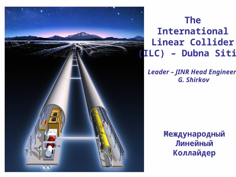
TheInternational
Linear Collider(ILC) – Dubna Siting
Leader – JINR Head Engineer G. Shirkov
МеждународныйЛинейныйКоллайдер
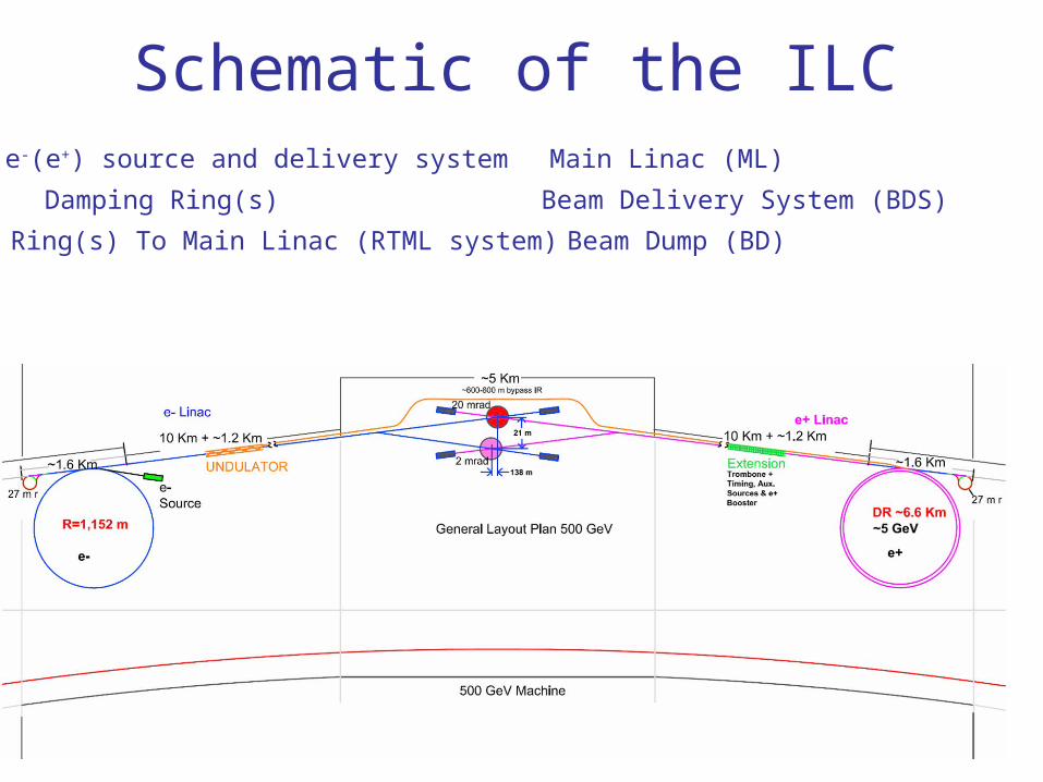
Schematic of the ILCe-(e+) source and delivery system
Damping Ring(s)
Ring(s) To Main Linac (RTML system)
Main Linac (ML)
Beam Delivery System (BDS)
Beam Dump (BD)
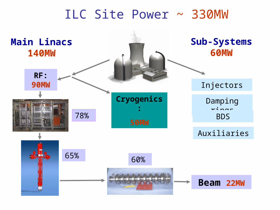
ILC Site Power ~ 330MW
Sub-Systems 60MW
Main Linacs 140MW
Cryogenics:
50MW
RF: 90MW
65%
78%
60%
Beam 22MW
Injectors
Damping rings
Auxiliaries
BDS
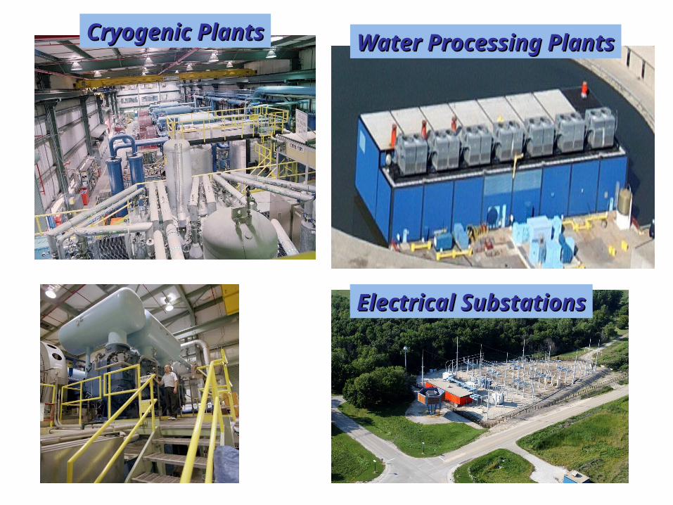
Cryogenic PlantsCryogenic Plants Water Processing PlantsWater Processing Plants
Electrical SubstationsElectrical Substations
ILC siting and conventional facilities in Dubna region

Joint Institute for Nuclear Research
Dubna, RussiaInternational Intergovernmental Organization
18 member states; 4 associate members
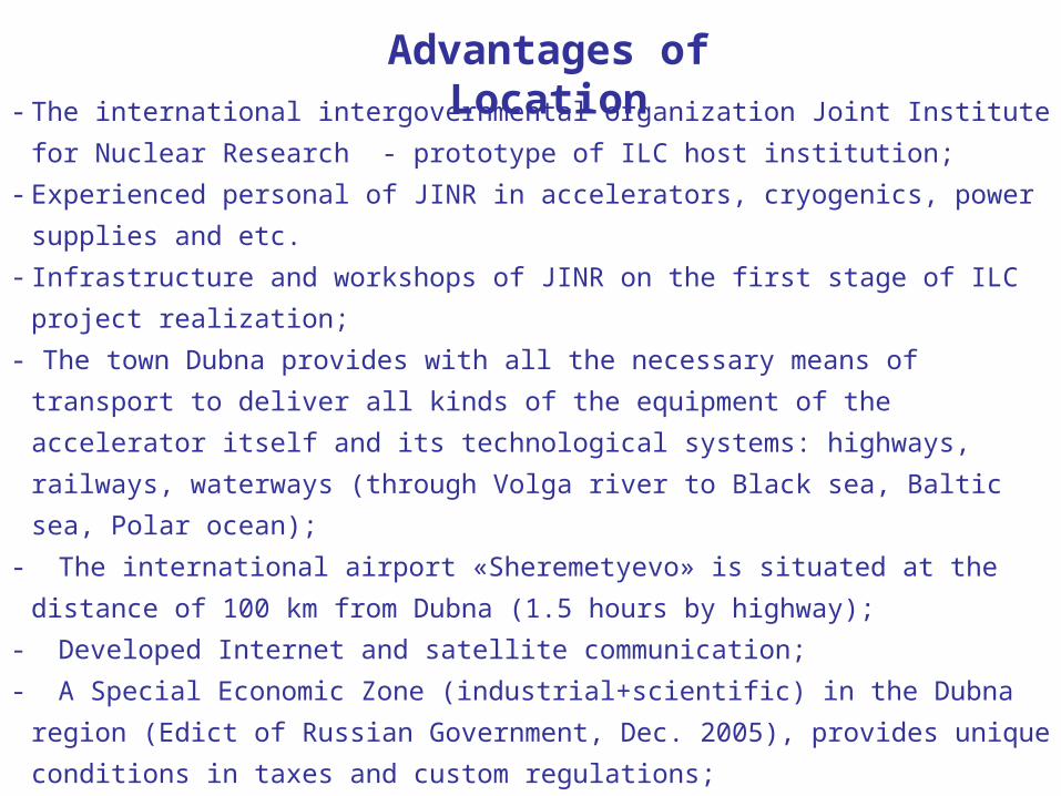
- The international intergovernmental organization Joint Institute for Nuclear Research -
prototype of ILC host institution;
- Experienced personal of JINR in accelerators, cryogenics, power supplies and etc.
- Infrastructure and workshops of JINR on the first stage of ILC project realization;
- The town Dubna provides with all the necessary means of transport to deliver all kinds of
the equipment of the accelerator itself and its technological systems: highways, railways,
waterways (through Volga river to Black sea, Baltic sea, Polar ocean);
- The international airport «Sheremetyevo» is situated at the distance of 100 km from
Dubna (1.5 hours by highway);
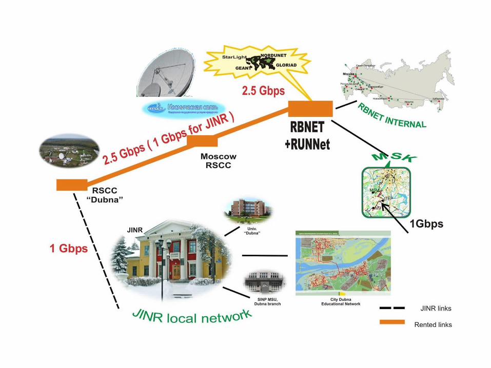
- Developed Internet and satellite communication;
- A Special Economic Zone (industrial+scientific) in the Dubna region (Edict of Russian
Government, Dec. 2005), provides unique conditions in taxes and custom regulations;
- A positive reaction received in preliminary discussions with the interested
governmental persons and organizations in Russia.
Advantages of Location
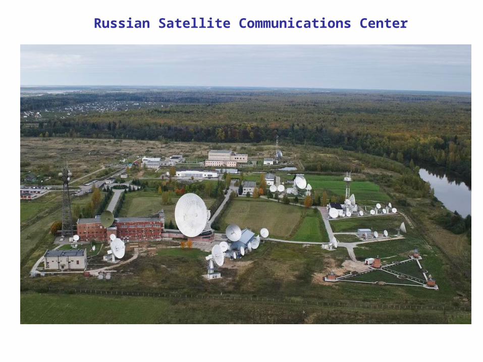
Russian Satellite Communications Center
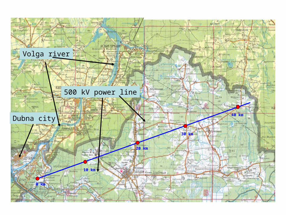
0 km
10 km
20 km
30 km
40 km
500 kV power line
Volga river
Dubna city
The area is thinly populated, the path of the accelerator traverses 2 small
settlements and a railway with light traffic between Taldom and Kimry.
Possible “line” crosses only the railway to Savelovo (of low utilization) and
the River Hotcha with a very small flow rate.
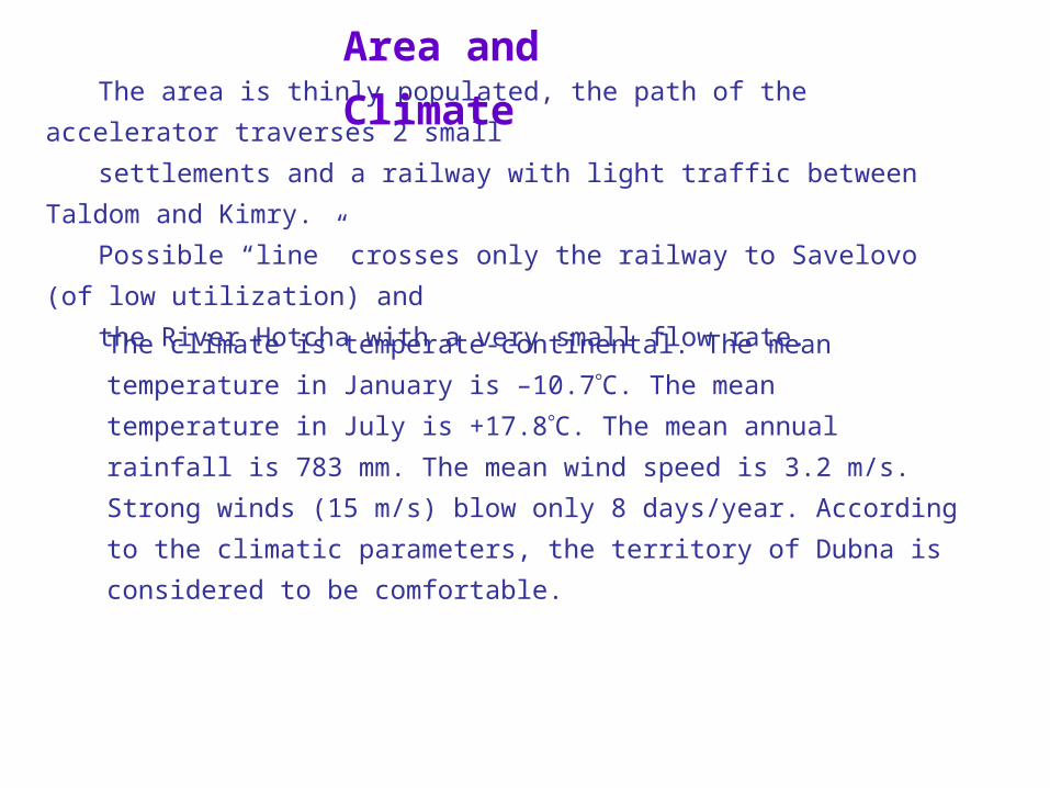
The climate is temperate-continental. The mean temperature in January
is –10.7С. The mean temperature in July is +17.8С. The mean annual
rainfall is 783 mm. The mean wind speed is 3.2 m/s. Strong winds (15
m/s) blow only 8 days/year. According to the climatic parameters, the
territory of Dubna is considered to be comfortable.
Area and Climate
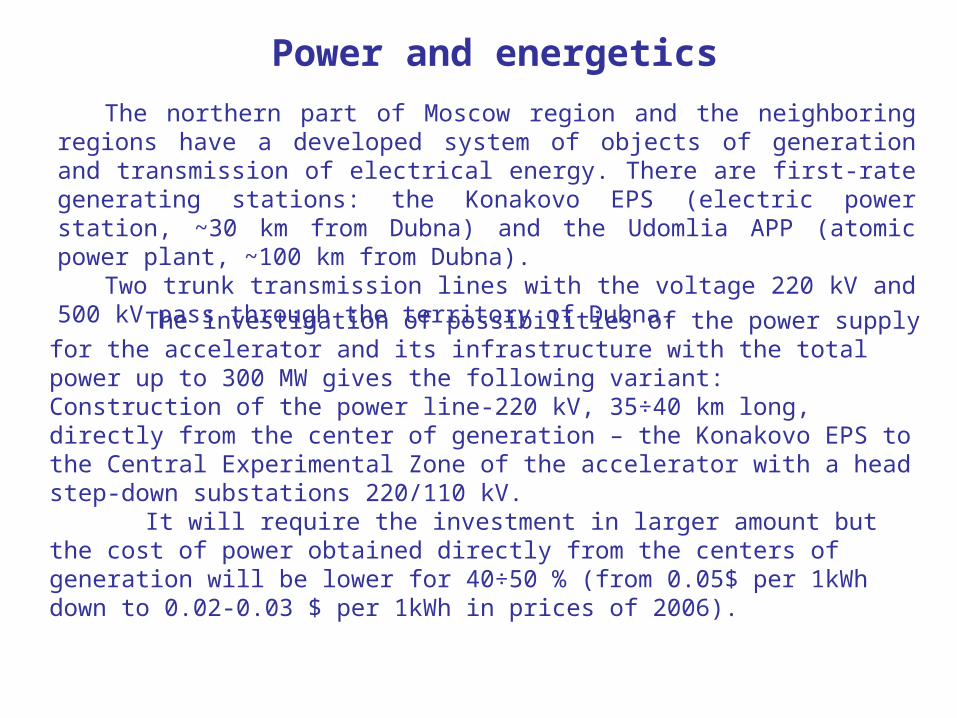
Power and energetics
The northern part of Moscow region and the neighboring regions have a developed system of objects of generation and transmission of electrical energy. There are first-rate generating stations: the Konakovo EPS (electric power station, ~30 km from Dubna) and the Udomlia APP (atomic power plant, ~100 km from Dubna).
Two trunk transmission lines with the voltage 220 kV and 500 kV pass through the territory of Dubna.
The investigation of possibilities of the power supply for the accelerator and its infrastructure with the total power up to 300 MW gives the following variant:Construction of the power line-220 kV, 35÷40 km long, directly from the center of generation – the Konakovo EPS to the Central Experimental Zone of the accelerator with a head step-down substations 220/110 kV.
It will require the investment in larger amount but the cost of power obtained directly from the centers of generation will be lower for 40÷50 % (from 0.05$ per 1kWh down to 0.02-0.03 $ per 1kWh in prices of 2006).
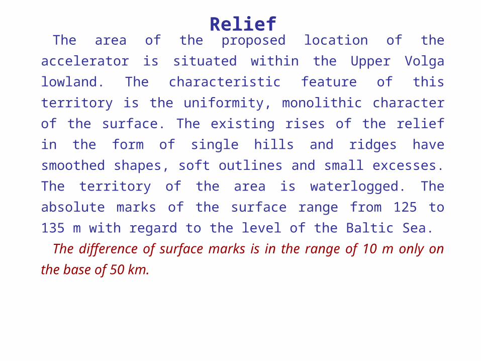
The area of the proposed location of the accelerator is situated
within the Upper Volga lowland. The characteristic feature of this
territory is the uniformity, monolithic character of the surface. The
existing rises of the relief in the form of single hills and ridges have
smoothed shapes, soft outlines and small excesses. The territory of
the area is waterlogged. The absolute marks of the surface range
from 125 to 135 m with regard to the level of the Baltic Sea.
The difference of surface marks is in the range of 10 m only on
the base of 50 km.
Relief
The area of the proposed location of the accelerator is situated within the Russian
plate – a part of the Eastern European ancient platform – a stable, steady structural
element of the earth’s crust.
The Russian plate, like all the other plates, has a well-defined double-tier
structure. The lower tier or structural floor is formed by the ancient – lower
Proterozoic and Archaean strata of metamorphic and abyssal rocks, which are more
than 1.7 billion of years old. All these strata are welded into a single tough body –
the foundation of the platform. The area of the ILC accelerator is located in the
southern part of a very gently sloping saucer-shaped structure – the Moscovian
syneclise.
Alluvial deposits i.e. fine water-saturated sands, 1-5 m of thickness. Below one
can find semisolid drift clay of the Moscovian glaciation with exception of detritus
and igneous rocks. The thickness of moraine deposits is 30-40 m.
Geology
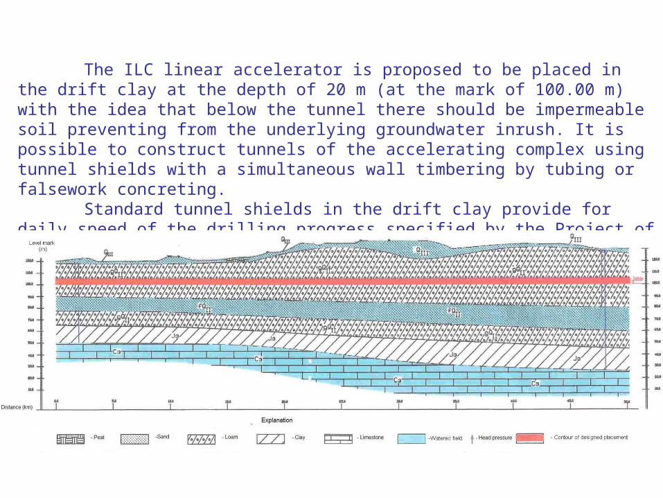
The ILC linear accelerator is proposed to be placed in the drift clay at the depth of 20 m (at the mark of 100.00 m) with the idea that below the tunnel there should be impermeable soil preventing from the underlying groundwater inrush. It is possible to construct tunnels of the accelerating complex using tunnel shields with a simultaneous wall timbering by tubing or falsework concreting.
Standard tunnel shields in the drift clay provide for daily speed of the drilling progress specified by the Project of the accelerator (it is needed for tunnel approximately 2.5 y’s).
BCD document (Conventional Facilities part)
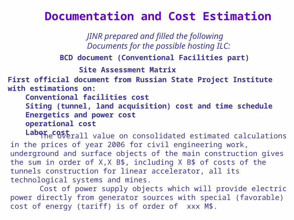
Documentation and Cost Estimation
Site Assessment MatrixFirst official document from Russian State Project Institute with estimations on: Conventional facilities cost Siting (tunnel, land acquisition) cost and time schedule Energetics and power cost operational cost Labor cost
JINR prepared and filled the followingDocuments for the possible hosting ILC:
The overall value on consolidated estimated calculations in the prices of year 2006 for civil engineering work, underground and surface objects of the main construction gives the sum in order of X,X B$, including X B$ of costs of the tunnels construction for linear accelerator, all its technological systems and mines.
Cost of power supply objects which will provide electric power directly from generator sources with special (favorable) cost of energy (tariff) is of order of xxx M$.

Structure
JINR participation in ILC
Accelerator physics & techniques
Detectors Particle PhysicsDetector concepts
R&DExperiments &Tests
Program for new physics
& experiments
R&DTest facilitiesInfrastructure
SitingSafety
Scientific Council of JINR (20.01.2006):• encourages JINR to be involved in the ILC design effort and to invest appropriate resources in scientific and technological developments to support its ability to play a leading role in the ILC project;• supports the intention of JINR to participate actively in the ILC project and the possible interest of JINR to host the ILC
JINR Committee of Plenipotentiaries approved this recommendation on 25.03.2006The Committee of Plenipotentiary Representatives of the Governments of the Member States is the supreme body governing the Institute.
JINR at ILC accelerator
Plans on opening of new themeJINR participation in design, construction and testing of prototype elements of the ILC accelerator complex (2007-2009).
Studying problem and main goal of researches:Development and creation of accelerator complex elements, study of the beam dynamics in linear colliders.
Participating countries and international organizationsBelarus, Germany, Italy, Russia, USA, Japan, CERN
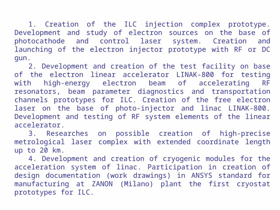
1. Creation of the ILC injection complex prototype. Development and study of electron sources on the base of photocathode and control laser system. Creation and launching of the electron injector prototype with RF or DC gun.
2. Development and creation of the test facility on base of the electron linear accelerator LINAK-800 for testing with high-energy electron beam of accelerating RF resonators, beam parameter diagnostics and transportation channels prototypes for ILC. Creation of the free electron laser on the base of photo-injector and linac LINAK-800. Development and testing of RF system elements of the linear accelerator.
3. Researches on possible creation of high-precise metrological laser complex with extended coordinate length up to 20 km.
4. Development and creation of cryogenic modules for the acceleration system of linac. Participation in creation of design documentation (work drawings) in ANSYS standard for manufacturing at ZANON (Milano) plant the first cryostat prototypes for ILC.
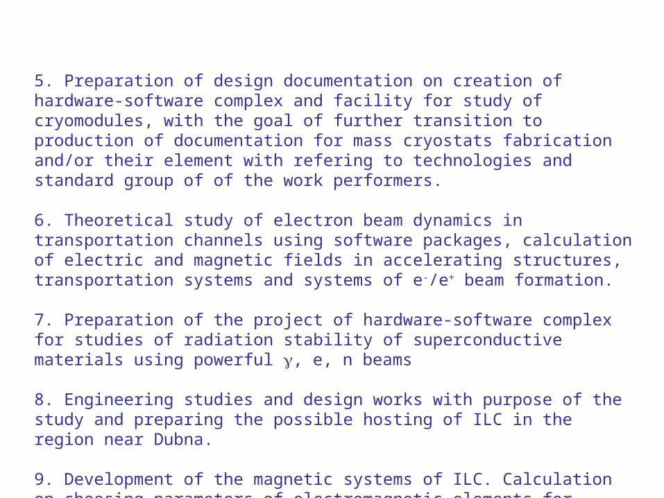
5. Preparation of design documentation on creation of hardware-software complex and facility for study of cryomodules, with the goal of further transition to production of documentation for mass cryostats fabrication and/or their element with refering to technologies and standard group of of the work performers.
6. Theoretical study of electron beam dynamics in transportation channels using software packages, calculation of electric and magnetic fields in accelerating structures, transportation systems and systems of e-/e+ beam formation.
7. Preparation of the project of hardware-software complex for studies of radiation stability of superconductive materials using powerful , e, n beams
8. Engineering studies and design works with purpose of the study and preparing the possible hosting of ILC in the region near Dubna.
9. Development of the magnetic systems of ILC. Calculation on choosing parameters of electromagnetic elements for Damping Rings (DR). Development and creation of the magnetic systems on base of superconducting and warm electromagnets, also for constant magnet variant.
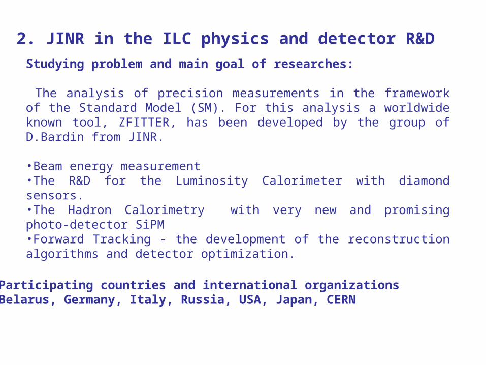
2. JINR in the ILC physics and detector R&D
Studying problem and main goal of researches:
The analysis of precision measurements in the framework of the Standard Model (SM). For this analysis a worldwide known tool, ZFITTER, has been developed by the group of D.Bardin from JINR.
•Beam energy measurement •The R&D for the Luminosity Calorimeter with diamond sensors.•The Hadron Calorimetry with very new and promising photo-detector SiPM•Forward Tracking - the development of the reconstruction algorithms and detector optimization.
Participating countries and international organizationsBelarus, Germany, Italy, Russia, USA, Japan, CERN
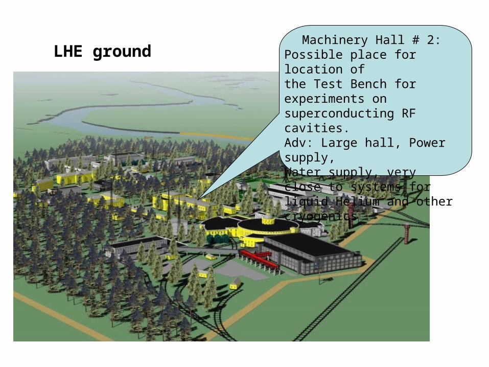
LHE groundMachinery Hall # 2:
Possible place for location of the Test Bench for experiments on superconducting RF cavities.Adv: Large hall, Power supply,Water supply, very close to systems for liquid Helium and other cryogenics
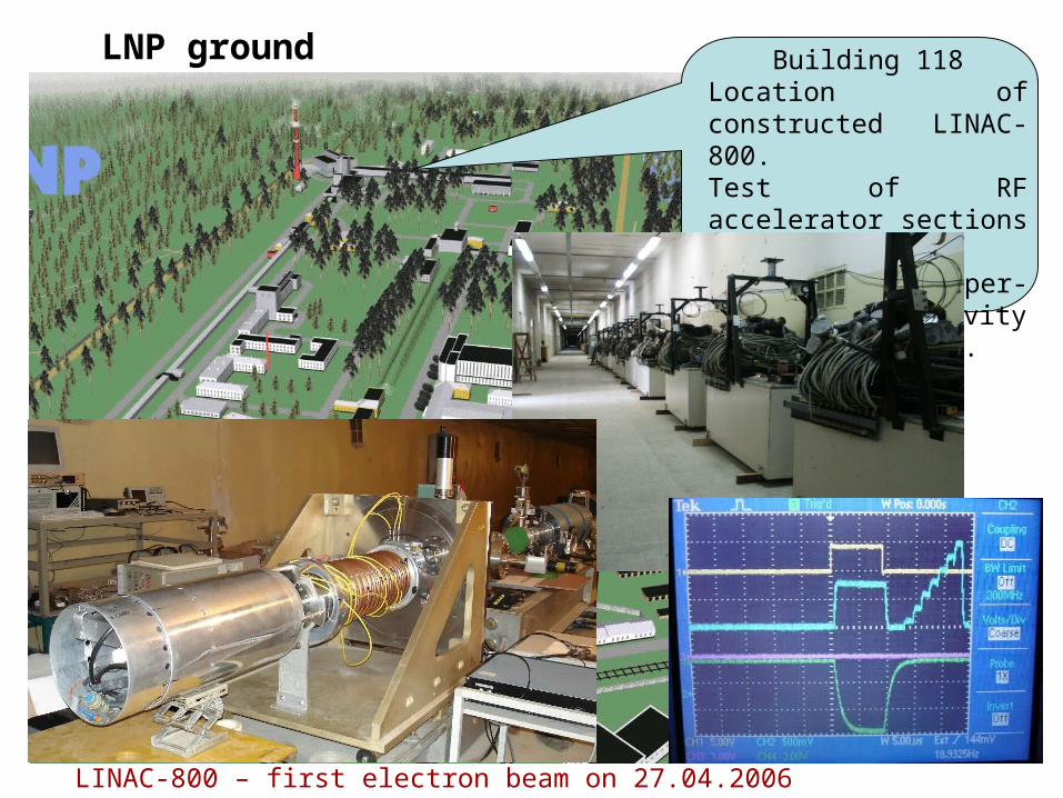
LNP ground Building 118Location of constructed LINAC-800.Test of RF accelerator sections and cryo modulesLINAC with super-conducting RF cavity(power,water, ...
LINAC-800 – first electron beam on 27.04.2006
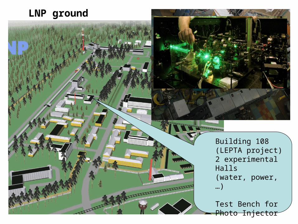
LNP ground
Building 108 (LEPTA project)2 experimental Halls(water, power, …)
Test Bench forPhoto Injector

Welcome to JINR (Dubna)Welcome to JINR (Dubna)
The materials of the talk of G.Shirkov at CALC-2006 were used.
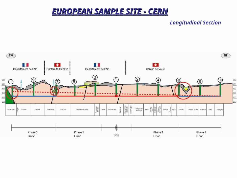
Longitudinal Section
EUROPEAN SAMPLE SITE - CERNEUROPEAN SAMPLE SITE - CERN
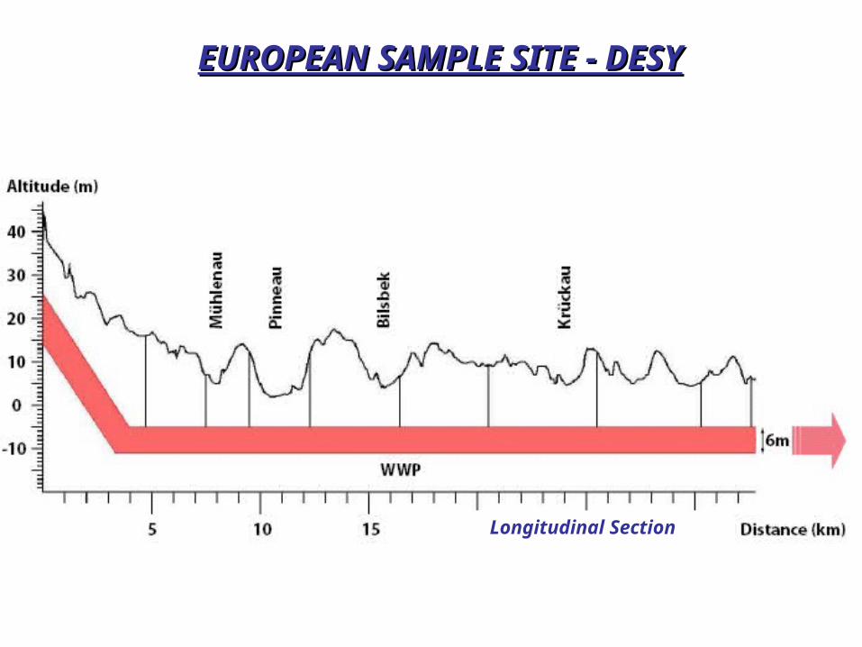
EUROPEAN SAMPLE SITE - DESYEUROPEAN SAMPLE SITE - DESY
Longitudinal Section
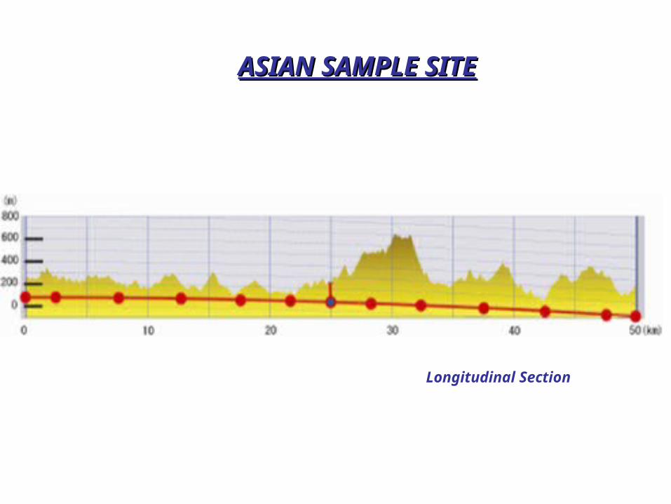
ASIAN SAMPLE SITEASIAN SAMPLE SITE
Longitudinal Section
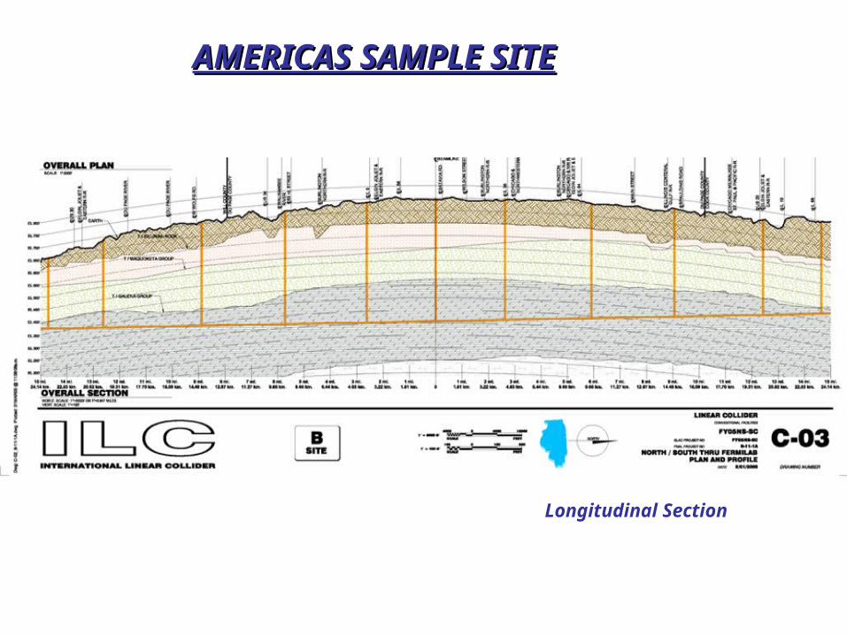
AMERICAS SAMPLE SITEAMERICAS SAMPLE SITE
Longitudinal Section


![1. Общие положения · 23 августа 2017 г. № 816 [2]; ... собой наложенную на линейный календарь матрицу, имеющую](https://static.fdocument.pub/doc/165x107/5ec5b31574b3aa2b4907d7db/1-23-f-2017-a-816-2-.jpg)