The Experience of Risk Assessment and its Future ... · and its Future Utilization at Rokkasho...
26
JNFL 1 The Experience of Risk Assessment and its Future Utilization at Rokkasho Reprocessing Plant Mr. Kazumi Takebe, Mr. Yoshikazu Tamauchi, Mr. Katsuyoshi Omori, Mr. Kunihiko Ogiya, Mr. Yoshiaki Hayashi, and Dr. Shingo Matsuoka. Safety Technology Office, Japan Nuclear Fuel Limited (JNFL). October 16-18, 2007
Transcript of The Experience of Risk Assessment and its Future ... · and its Future Utilization at Rokkasho...
JNFL1
The Experience of Risk Assessment and its Future Utilization at Rokkasho
Reprocessing Plant
Mr. Kazumi Takebe, Mr. Yoshikazu Tamauchi, Mr. Katsuyoshi Omori, Mr. Kunihiko Ogiya, Mr. Yoshiaki
Hayashi, and Dr. Shingo Matsuoka.
Safety Technology Office, Japan Nuclear Fuel Limited (JNFL).
October 16-18, 2007
JNFL2
Contents
Safety features of Rokkasho Reprocessing Plant (RRP)
Identification of events and PSA of RRP
An example of detailed PSA
Conclusion
Development and application of the Simplified PSA
Possible utilization of risk information
JNFL3
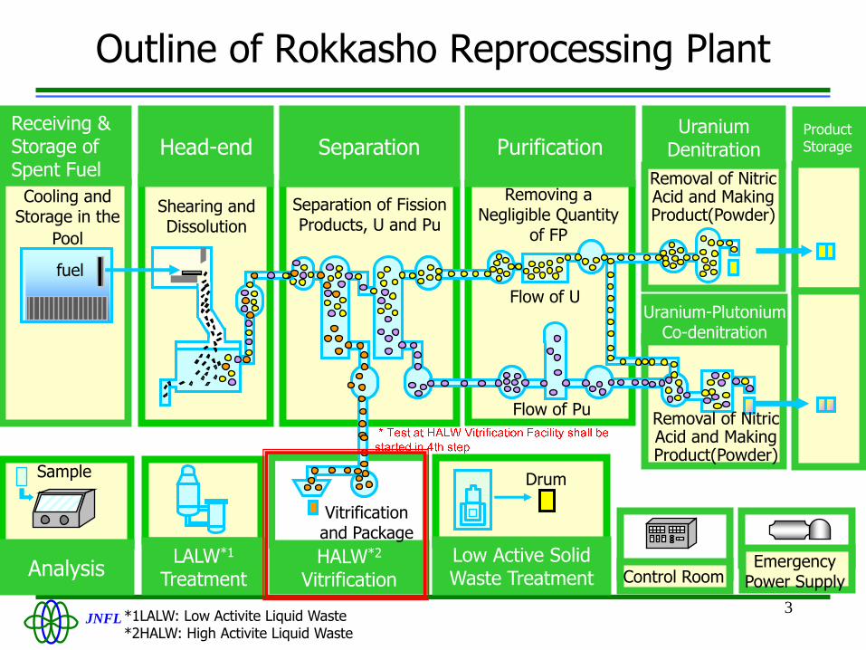
Shearing and Dissolution
Separation of Fission Products, U and Pu
Removing a Negligible Quantity
of FP
Purification
HALW*2
Vitrification
Uranium Denitration
Vitrificationand Package
Flow of U
Receiving & Storage of Spent Fuel
Cooling and Storage in the
Pool
Low Active Solid Waste Treatment
LALW*1
TreatmentAnalysis
DrumSample
Head-end
Removal of Nitric Acid and Making Product(Powder)
Flow of Pu
fuel
Separation
Control RoomEmergency
Power Supply
Uranium-Plutonium Co-denitration
Removal of Nitric Acid and Making Product(Powder)
Product Storage
*1LALW: Low Activite Liquid Waste*2HALW: High Activite Liquid Waste
Outline of Rokkasho Reprocessing Plant

JNFL4
Safety features of RRP
Safety features of RRP
Confinement ofRadioactive Materials
Radiation Shielding
Criticality Safety
A-seismic Design Decay HeatRemoval
Aircraft CrushProtection
Discharge Controlof Radioactive Effluents
Fire & ExplosionProtection
Multiple Protection Policy
JNFL5
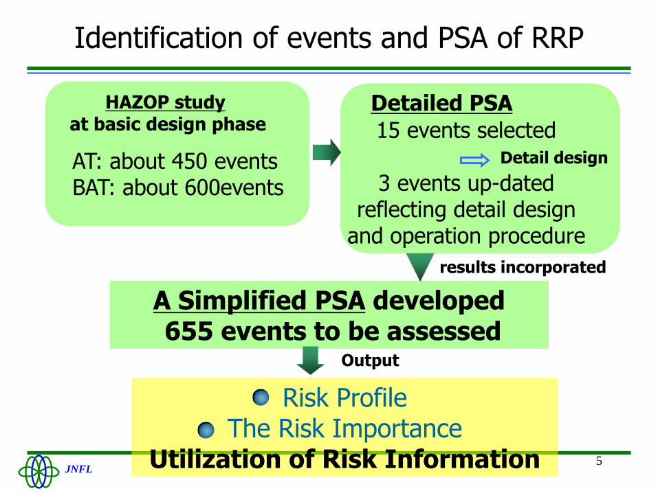
Identification of events and PSA of RRP
Risk ProfileThe Risk Importance
Utilization of Risk Information
A Simplified PSA developed655 events to be assessed
Output
Detailed PSAHAZOP studyat basic design phase
AT: about 450 eventsBAT: about 600events
15 events selected
results incorporated
Detail design
3 events up-dated reflecting detail design
and operation procedure

JNFL6
An example of detailed PSA
Loss of Hydrogen Gas Scavenging Function in Plutonium Solution vessels
ref.4) Tamauchi, Y. et al., “Application of Probabilistic Safety Assessment to Rokkasho Reprocessing Plant (1); The Occurrence Frequency of Loss of H2 Scavenging Function in Pu Solution Vessel,” Nihon- Genshiryoku-Gakkai Shi ( J. At. Energy Soc. Jpn.), 4[5], 334-346 (2006), [in Japanese].

JNFL7
Outline of scavenging air supply system
Safety Compressed Air Supply System
Safety Compressor
Normal Compressed Air Supply System
Scavenging Air
Service Air
Pu Purification Facility
Vessel
PP
P
F
P:Pressure gaugeF:Flow meter
Schematic diagram of the scavenging air supply system

JNFL8
Accident scenarios and evaluation method
Failure of three safety compressors
Connecting Normal compressed air to the
safety scavenging system
Using service air supply system
Success
Keep scavenging air
Failure
Initiating Events (IE)
Safety functions
Leakage from piping or valves
Success Failure
Loss of hydrogen scavenging function
Accident frequency assessment ET/FT method
Failure rate of equipment Selected from Published literatures
Failure rate of air compressor, air operated valve, etc.:→referred from database of THORP and Tokai Reprocessing Plant
Human error probability THERP method
Evaluation Method and Database
JNFL9
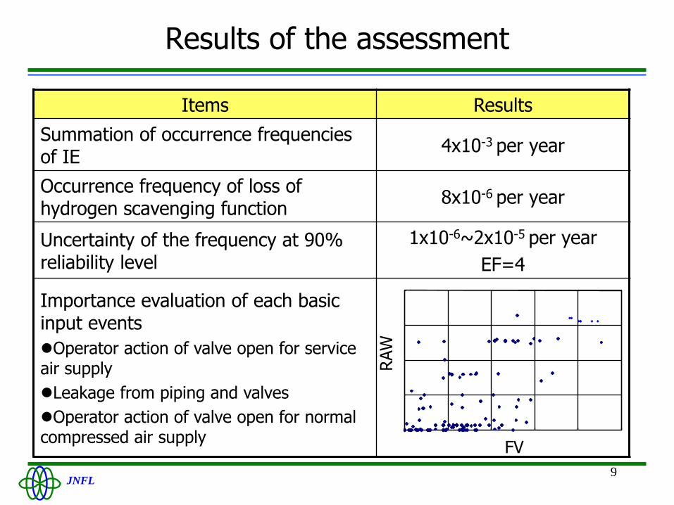
Results of the assessment
Items Results
Summation of occurrence frequencies of IE
4x10⁻³ per year
Occurrence frequency of loss of hydrogen scavenging function
8x10⁻⁶ per year
Uncertainty of the frequency at 90% reliability level
1x10⁻⁶~2x10⁻⁵ per year
EF=4
Importance evaluation of each basic input events
Operator action of valve open for service air supply
Leakage from piping and valves
Operator action of valve open for normal compressed air supply
FV
RAW
JNFL10
Development and application of the Simplified PSA
ref.3) Tatsuo SHOUJI, Yuuji KOHATA, Kazumi TAKEBE, Yoshikazu TAMAUCHI, Kazuya
HAYASHI, Katsuya KUROSU, “A Study on Graded Approsch for Risk Assessment of the
Rokkasho Reprocessing Plant”, Paper No. 460, Proceedings of GLOBAL 2005, Tsukuba, Japan,
Oct. 9-13, 2005

JNFL11
Development of Simplified PSA
A Simplified PSA has been developed
Detailed PSA
FTA results of utility facilitiesHuman reliability Analysis, etc.
Results IncorporatedComparison of results of Simplified PSA and Detailed PSA Method
It can evaluate systematically evaluate the risk of RRPIt can evaluate the importance of systems, componentsand Human actionIt is possible to use the MS Excel sheet for all evaluationThe formula corresponding FTA are inputted in the sheet

JNFL12
Outline of simplified PSA procedure 1
Simplified PSA consist of several MS Excel sheet as follow,
Input sheets(a) Safety function/System Matrix(b) Utilities/Systems datasheet(c) Consequence evaluation sheet
Output sheets(d) Event tree display sheet for each event(e) Consequence evaluation result display sheet for each event(f) Importance evaluation result display sheet for each event (g) Risk of all events display sheet(h) Importance related to risk of reprocessing plant

JNFL13
Outline of simplified PSA procedure 2
Design information
Identification of hazards and accident sequences
Identification of safety functions
Identification of systems, components and human actions essential to the safety functions
Design and Operation Information input and summarized in (a) Safety function/System Matrix

JNFL14
C om ponent
Event
PS-1
-2
M S-1
-2
-3
-4
Failure rate M TTR Unavailability M TTR Failure rate UnavailabilityM S-1 M S-2 M S-3 M S-4 M S-5 (/h) (h) (/d) (h) (/h) (/d)
Activecom p.
Rem ote-operated valve for service air supply toPu concentrate vessel
○3.00E-03 0 3.00E-03
M anual-operated valve for norm al com pressed airsupply to safety com pressed air supply system
○ ○1.00E-04 0 1.00E-04
Passive Scavenging air supply line in Pu purification ○ ○ ○ 1.00E-08 24 9.59E-09 2.40E-07
com p. Service air supply line in Pu purification facility(piping & valves)
○
1.00E-08 24 9.59E-09 2.40E-07
Norm al com pressed air supply line to safetycom pressed air supply system (piping & valves)
○ ○1.00E-08 24 9.59E-09 2.40E-07
The value consideringtim e m argin
Function of on-dutyFunction of on-
dem and
Pu C oncentrate VesselLoss of H 2 scavenging function
The contents of safety functions
C ontinuous feeding of scavenging air from "Safety C om pressed AirSupply System "
Em ergency feeding of service air from "Safety C om pressed Air SupplySystem " by low w arning of flow rate
C om pressed air feeding from "Norm al C om pressed Air Supply System "by low alarm of pressure
Prevention
Tim e m argin(h)
1
Safety function
-
C om pressed air feeding from "Norm al C om pressed Air Supply System "by low w arning of flow rate
Loss ofscavengingfunction
Tim e tooperate(h)
start operation
Increasing ofH 2 density
Releasesequence
Outline of simplified PSA procedure 3
Excerpt from (a) Safety function/System Matrix
Input failure rates for system, component,
human action related to initiating event and
safety function
A list “Database of system, component and human action” have been set
conservatively based on the published documents. Human error rate was determined based on detailed PSA.
Markup components essential for safety
function
Describe Components , human actions relating toprevention systems and
safety functions
Enter the Safety functions
Enter the Prevention systems against the
accident
Input the component and kind of event for
evaluation
JNFL15
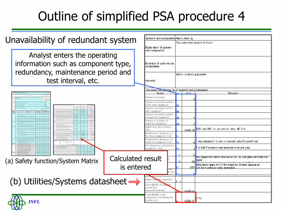
Outline of simplified PSA procedure 4
Num ber of system s
Num ber of needed system sof O n-duty equipm ent
Num ber of system s of O n-duty equipm ent
Num ber of needed system sof stand-by equipm ent
Num ber of system s ofstand-by equipm ent
failure rate(per system s)(/h)
M aintenance frequency ofO n-duty equipm ent (/yr)
M aintenance frequency ofstand-by equipm ent (/yr)
Test frequency of stand-byequipm ent (/yr)
m aintenance tim e(h)
M ean tim e to repair (h)
C C F factor2
Unavailability of signal andoperation,etc. related to thestand-by equipm ent start
failure rate (O n-duty)(/h)eff
unavailability of stand bysystem (O n-dem and)(/dem and)
Unabailability of thecom ponent considering thebackup, etc.
eff
Unavailability of redundant system
(b) Utilities/Systems datasheet
(a) Safety function/System Matrix
Analyst enters the operating information such as component type, redundancy, maintenance period and
test interval, etc.
Function of on-duty Function of on-dem and
failure rate M TTR Unavailability M TTR Failure rate Unavailability
(/h) (h) (/d) (h) (/h) (/d)
3.00E-03 0 3.00E-03
1.00E-04 0 1.00E-04
1.00E-08 24 9.59E-09 2.40E-07
1.00E-08 24 9.59E-09 2.40E-07
1.00E-08 24 9.59E-09 2.40E-07
1.00E-01 0 1.00E-01
1.00E-07 24 9.59E-08 2.40E-06
1.00E-04 0 1.00E-04
1.00E-07 24 9.59E-08 2.40E-06
1.00E-04 0 1.00E-04
1.00E-03 0 1.00E-03
1.00E-03 0 1.00E-03
1.00E-03 0 1.00E-03
1.00E-04 0 1.00E-04
1.00E-02 0 1.00E-02
Relation of initiating events and detection
○
○ ○
○ ○
○ ○
The value consideringtim e m argin
System s, com ponents and hum an actionsrelated to safety functions
Action of valve open for norm al com pressed air supply tosafety com pressed air supply system
Perception of loss of scavenging air through flow rate lowalarm
Action of valve open for service air supply to Puconcentrate vesselPerception of failure of safety com pressed air supplysystem through pressure low alarm
Pressure m eter for scavenging air in safety com pressedair supply system (two-redundant system )
Low alarm of pressure of scavenging air in safetycom pressed air supply system (two-redundant system )
Flow m eter for scavenging air to Pu concentrate vessel(installed for each vessel)
Low alarm of flow rate of scavenging air to Puconcentrate vessel(installed for each vessel)
Service air supply line in Pu purification facility (piping &valves)
Norm al com pressed air supply line to safety com pressedair supply system (piping & valves)
Scavenging air supply line in Pu purification facility(piping & valves)
Rem ote-operated valve for service air supply to Puconcentrate vesselM anual-operated valve for norm al com pressed air supplyto safety com pressed air supply system
Initiating events(Failure of individualsystem s below)
Scavenging air supply line in Pu purification facility (piping & valves)
Safety cooling water supply system
Safety com pressed air supply system
Em argency electric supply system
Low alarm of flow rate ofscavenging air to Pu concentratevessel(installed for each vessel)
Low alarm of pressure ofscavenging air in safetycom pressed air supply system(two-redundant system )
Calculated result is entered
C om ponent
Event
PS-1
-2
M S-1
-2
-3
-4
M S-1 M S-2 M S-3 M S-4 M S-5
Activecom p.
Rem ote-operated valve for service air supply toPu concentrate vessel
○
M anual-operated valve for norm al com pressed airsupply to safety com pressed air supply system
○ ○
Passive Scavenging air supply line in Pu purification ○ ○ ○com p. Service air supply line in Pu purification facility
(piping & valves)○
Norm al com pressed air supply line to safetycom pressed air supply system (piping & valves)
○ ○
I&C Flow m eter for scavenging air to Pu concentrate vessel(installedfor each vessel)
○ ○
Low alarm of flow rate of scavenging air to Pu concentrate vessel(installed for each vessel)
◎ ◎
Pressure m eter for scavenging air in safety com pressed air supplysystem (tw o-redundant system )
○
Low alarm of pressure of scavenging air in safety com pressed airsupply system (tw o-redundant system )
◎
Perception of loss of scavenging air through flow rate low alarm ○
Action of valve open for service air supply to Pu concentratevessel
○
Perception of failure of safety com pressed air supply systemthrough pressure low alarm
○ ○
Action of valve open for norm al com pressed air supply to safetycom pressed air supply system
○ ○
Norm al cooling water supply systemNorm al cooling water supply system for F facilitybackup cooling water supply systemSafety cooling water supply systemSafety cooling water supply system for F facilitygeneral cooling water supply system 1general cooling water supply system 2Norm al/buckup com pressed air supply systemSafety com pressed air supply systemNorm al steam supply system
Norm al electric supply system Backup electric supply system Em argency electric supply system Em argency electric supply system for F facility
Pu C oncentrate VesselLoss of H 2 scavenging function
The contents of safety functions
C ontinuous feeding of scavenging air from "Safety C om pressed AirSupply System "
Em ergency feeding of service air from "Safety C om pressed Air SupplySystem " by low warning of flow rate
C om pressed air feeding from "Norm al C om pressed Air Supply System "by low alarm of pressure
electricsystem
supportsystem
Prevention
Hum anaction
Tim e m argin(h)
1
Safety function
-
C om pressed air feeding from "Norm al C om pressed Air Supply System "by low warning of flow rate
Loss ofscavengingfunction
Tim e tooperate(h)
start operation
Increasing ofH 2 density
Releasesequence

JNFL16
Norm al cooling water supply systemNorm al cooling water supply system for F facilitybackup cooling water supply systemSafety cooling water supply systemSafety cooling water supply system for F facilityG eneral cooling water supply system 1G eneral cooling water supply system 2Norm al/buckup com pressed air supply systemSafety com pressed air supply systemNorm al steam supply system
Norm al electric supply system Backup electric supply system Em argency electric supply system Em argency electric supply system for F facility
Electricsystem
System s, com ponents and hum an actions related to safetyfunctions
Prevention Safety function
Supportsystem
Outline of simplified PSA procedure 5
Excerpt from (a) Safety function/System Matrix
Unavailability of such support systems as utilities, which related to many events, has been set in (a), with simplified
fault tree equation based on detailed PSA results.
. Therefore, analysts should select the support system
essential to the safety functions and mark the symbols

JNFL17
Outline of simplified PSA procedure 6
occurrencefrecency(1/y)
Dose (m Sv)
Risk(death/
y)
S 0.0E+00 0 0.0E+00
[PS-1]
S 8.4E-05 0 0.0E+00
F
S 7.7E-05 0 0.0E+00
F
S Pu conc. solution 3.8E-06 0 0.0E+00
[PS-2] 1.5m 3
F
S Pu conc. solution 0.0E+00 2.3E-02 0.0E+00
1.5m 3
F
Pu conc. solution 0.0E+00 5.0E+00 0.0E+00F 1.5m 3
total0.0E+00
Increasing ofH2 density
-
Increasing ofH2 density
Loss ofscavengingfanction
O ccurance ofabnorm alcondition
Loss ofpreventionsystem s
Safety functions
Releasesequense
M S-3 M S-4 M S-5
Increasing ofH2 density
M S-1 M S-2Sourse team
Em ergencyfeeding ofservice airfrom "SafetyC om pressedAir SupplySystem " bylow warningof flow rate
C om pressedair feedingfrom"Norm alC om pressedAir SupplySystem " bylow alarm ofpressure
C om pressedair feedingfrom"Norm alC om pressedAir SupplySystem " bylow warningof flow rate
Theam ount ofm aterial
1.6E-04(/y) 1.0E+00(/d) 4.9E-01(/d) 4.7E-02(/d)
C ontinuousfeeding ofscavenging airfrom "SafetyC om pressed AirSupply System "
Running macro program
(a) Safety function/System Matrix
Calculated occurrence frequency is automatically
shown in form of ET (d)
Function of on-duty Function of on-dem and
failure rate M TTR Unavailability M TTR Failure rate Unavailability
(/h) (h) (/d) (h) (/h) (/d)
3.00E-03 0 3.00E-03
1.00E-04 0 1.00E-04
1.00E-08 24 9.59E-09 2.40E-07
1.00E-08 24 9.59E-09 2.40E-07
1.00E-08 24 9.59E-09 2.40E-07
1.00E-01 0 1.00E-01
1.00E-07 24 9.59E-08 2.40E-06
1.00E-04 0 1.00E-04
1.00E-07 24 9.59E-08 2.40E-06
1.00E-04 0 1.00E-04
1.00E-03 0 1.00E-03
1.00E-03 0 1.00E-03
1.00E-03 0 1.00E-03
1.00E-04 0 1.00E-04
1.00E-02 0 1.00E-02
Relation of initiating events and detection
○
○ ○
○ ○
○ ○
The value consideringtim e m argin
System s, com ponents and hum an actionsrelated to safety functions
Action of valve open for norm al com pressed air supply tosafety com pressed air supply system
Perception of loss of scavenging air through flow rate lowalarm
Action of valve open for service air supply to Puconcentrate vesselPerception of failure of safety com pressed air supplysystem through pressure low alarm
Pressure m eter for scavenging air in safety com pressedair supply system (two-redundant system )
Low alarm of pressure of scavenging air in safetycom pressed air supply system (tw o-redundant system )
Flow m eter for scavenging air to Pu concentrate vessel(installed for each vessel)
Low alarm of flow rate of scavenging air to Puconcentrate vessel(installed for each vessel)
Service air supply line in Pu purification facility (piping &valves)
Norm al com pressed air supply line to safety com pressedair supply system (piping & valves)
Scavenging air supply line in Pu purification facility(piping & valves)
Rem ote-operated valve for service air supply to Puconcentrate vesselM anual-operated valve for norm al com pressed air supplyto safety com pressed air supply system
Initiating events(Failure of individualsystem s below)
Scavenging air supply line in Pu purification facility (piping & valves)
Safety cooling w ater supply system
Safety com pressed air supply system
Em argency electric supply system
Low alarm of flow rate ofscavenging air to Pu concentratevessel(installed for each vessel)
Low alarm of pressure ofscavenging air in safetycom pressed air supply system(two-redundant system )
Input relation of initiating events and detection
C om ponent
Event
PS-1
-2
M S-1
-2
-3
-4
M S-1 M S-2 M S-3 M S-4 M S-5
Activecom p.
Rem ote-operated valve for service air supply toPu concentrate vessel
○
M anual-operated valve for norm al com pressed airsupply to safety com pressed air supply system
○ ○
Passive Scavenging air supply line in Pu purification ○ ○ ○com p. Service air supply line in Pu purification facility
(piping & valves)○
Norm al com pressed air supply line to safetycom pressed air supply system (piping & valves)
○ ○
I&C Flow m eter for scavenging air to Pu concentrate vessel(installedfor each vessel)
○ ○
Low alarm of flow rate of scavenging air to Pu concentrate vessel(installed for each vessel)
◎ ◎
Pressure m eter for scavenging air in safety com pressed air supplysystem (tw o-redundant system )
○
Low alarm of pressure of scavenging air in safety com pressed airsupply system (tw o-redundant system )
◎
Perception of loss of scavenging air through flow rate low alarm ○
Action of valve open for service air supply to Pu concentratevessel
○
Perception of failure of safety com pressed air supply systemthrough pressure low alarm
○ ○
Action of valve open for norm al com pressed air supply to safetycom pressed air supply system
○ ○
Norm al cooling water supply systemNorm al cooling water supply system for F facilitybackup cooling water supply systemSafety cooling water supply systemSafety cooling water supply system for F facilitygeneral cooling water supply system 1general cooling water supply system 2Norm al/buckup com pressed air supply systemSafety com pressed air supply systemNorm al steam supply system
Norm al electric supply system Backup electric supply system Em argency electric supply system Em argency electric supply system for F facility
Pu C oncentrate VesselLoss of H 2 scavenging function
The contents of safety functions
C ontinuous feeding of scavenging air from "Safety C om pressed AirSupply System "
Em ergency feeding of service air from "Safety C om pressed Air SupplySystem " by low warning of flow rate
C om pressed air feeding from "Norm al C om pressed Air Supply System "by low alarm of pressure
electricsystem
supportsystem
Prevention
Hum anaction
Tim e m argin(h)
1
Safety function
-
C om pressed air feeding from "Norm al C om pressed Air Supply System "by low warning of flow rate
Loss ofscavengingfunction
Tim e tooperate(h)
start operation
Increasing ofH 2 density
Releasesequence
Input time margin to accident
occurrence from initiating event

JNFL18
Outline of simplified PSA procedure 7
In the simplified PSA, consequence is represented as radiation dose to the publicThe radiation dose is calculated in (c) Consequence evaluation sheet The result is showed on (e) Consequence evaluation result display sheet based on five-factors formula *
*ref.7) Nuclear Fuel Cycle Facility Accident Analysis Handbook, NUREG/CR-6410, (1998).
ST = MAR*DR*ARF*RF*LPFDi=ST*R*X/Q*H
Quantification of consequence
Where,MAR:Material At RiskDR:Damage RatioARF:Airborne Release FractionRF:Respirable FractionLPF: Leak path Factor
ST:Source TeamDi:Effective Dose due to inhalation R:Inhalation ratioX/Q:Relative concentrationH:Coefficient for ingestion and inhalation
JNFL19
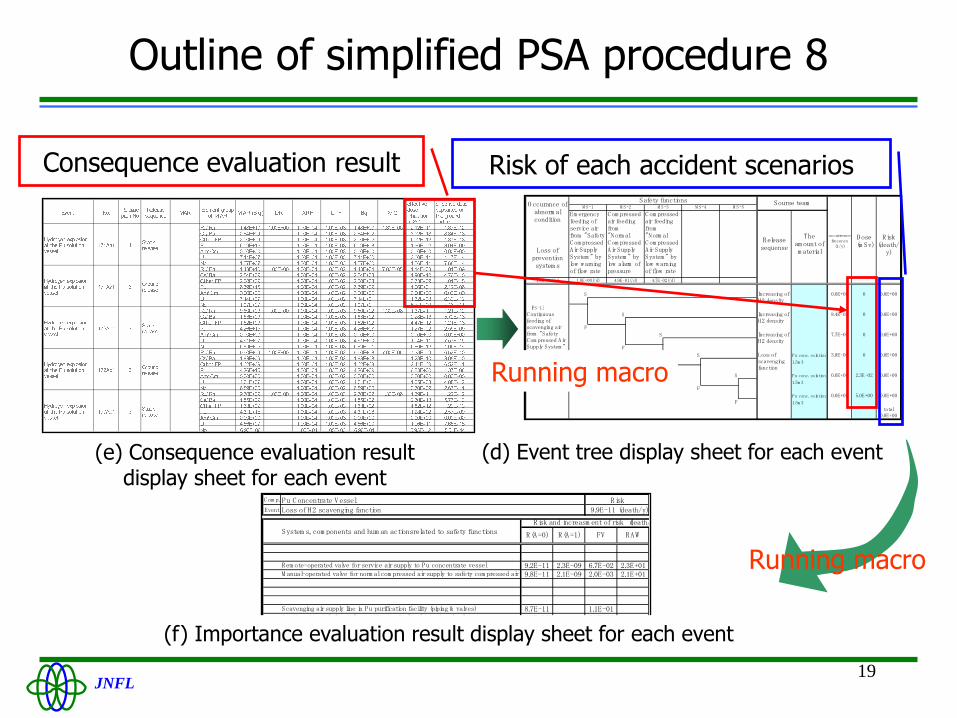
Outline of simplified PSA procedure 8
(e) Consequence evaluation result display sheet for each event
occurrencefrecency(1/y)
Dose (m Sv)
Risk(death/
y)
S 0.0E+00 0 0.0E+00
[PS-1]
S 8.4E-05 0 0.0E+00
F
S 7.7E-05 0 0.0E+00
F
S Pu conc. solution 3.8E-06 0 0.0E+00
[PS-2] 1.5m 3
F
S Pu conc. solution 0.0E+00 2.3E-02 0.0E+00
1.5m 3
F
Pu conc. solution 0.0E+00 5.0E+00 0.0E+00F 1.5m 3
total0.0E+00
Increasing ofH2 density
-
Increasing ofH2 density
Loss ofscavengingfanction
O ccurance ofabnorm alcondition
Loss ofpreventionsystem s
Safety functions
Releasesequense
M S-3 M S-4 M S-5
Increasing ofH2 density
M S-1 M S-2Sourse team
Em ergencyfeeding ofservice airfrom "SafetyC om pressedAir SupplySystem " bylow warningof flow rate
C om pressedair feedingfrom"Norm alC om pressedAir SupplySystem " bylow alarm ofpressure
C om pressedair feedingfrom"Norm alC om pressedAir SupplySystem " bylow warningof flow rate
Theam ount ofm aterial
1.6E-04(/y) 1.0E+00(/d) 4.9E-01(/d) 4.7E-02(/d)
C ontinuousfeeding ofscavenging airfrom "SafetyC om pressed AirSupply System "
(d) Event tree display sheet for each event
Consequence evaluation result Risk of each accident scenarios
Running macro
Running macro
C om p.Pu C oncentrate VesselEvent Loss of H2 scavenging fanction 9.9E-11 (death/y)
Risk and increasm ent of risk (death/y)System s, com ponents and hum an actionsrelated to safety functions
Rem ote-operated valve for service air supply to Pu concentrate vessel 9.2E-11 2.3E-09 6.7E-02 2.3E+01M anual-operated valve for norm al com pressed air supply to safety com pressed airsupply system
9.8E-11 2.1E-09 2.0E-03 2.1E+01
Scavenging air supply line in Pu purification facility (piping & valves) 8.7E-11 1.1E-01Service air supply line in Pu purification facility (piping & valves) 9.9E-11 5.3E-06
Norm al com pressed air supply line to safety com pressed air supply system (piping& valves)
9.9E-11 4.9E-064.3E-12 9.5E-10 9.6E-01 9.6E+00
FV
Risk
RAWR(A=0) R(A=1)
(f) Importance evaluation result display sheet for each event

JNFL20
Outline of simplified PSA procedure 9
(g) Risk of all events display sheet
1.E-05
1.E-03
1.E-01
1.E+01
1.E+03
Occurrence frequency (/yr)
Conse
quence
(m
Sv)
(h) Importance related to risk of reprocessing
plant.
FV index
RAW
1.E+00
1.E+01
1.E+02
1.E+03
1.E+04
1.E+05
1.E+001.E-051.E-10
JNFL21
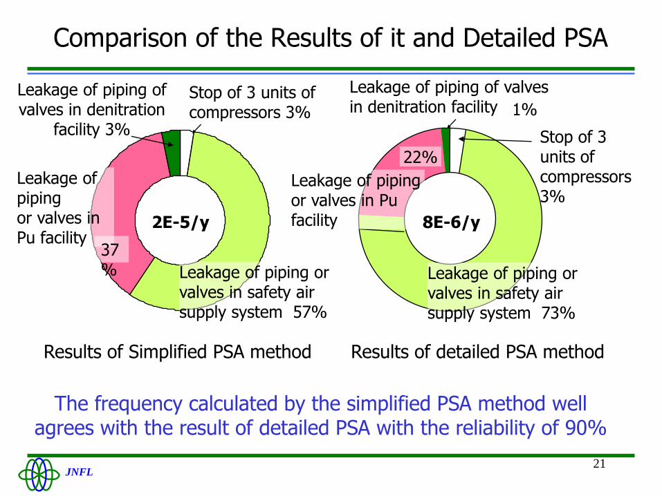
Comparison of the Results of it and Detailed PSA
Leakage of pipingor valves in Pu facility
1%
Stop of 3 units of compressors3%
Leakage of piping orvalves in safety airsupply system 73%
22%
8E-6/y
Leakage of pipingor valves in Pu facility
Leakage of piping of valves in denitration
facility 3%
Stop of 3 units ofcompressors 3%
Leakage of piping orvalves in safety airsupply system 57%
37%
2E-5/y
Results of detailed PSA methodResults of Simplified PSA method
Leakage of piping of valves in denitration facility
The frequency calculated by the simplified PSA method well agrees with the result of detailed PSA with the reliability of 90%

JNFL22
Possible utilization of risk information

JNFL23
A risk profile
An example of risk profile dotted according to the calculated results as of September 2007
1.E-06
1.E-05
1.E-04
1.E-03
1.E-02
1.E-01
1.E+00
1.E+01
1.E+02
1.E+03
1.E-10 1.E-08 1.E-06 1.E-04 1.E-02 1.E+00
Occurrence frequency (/yr)
Conse
quence
(m
Sv)

JNFL24
Risk importance for each components
An example of risk importance dotted according to the calculated results as of September 2007
FV index
RAW
1.E+00
1.E+01
1.E+02
1.E+03
1.E+04
1.E+05
1.E+001.E-051.E-10
JNFL25
Utilizing the risk information- future plan
Risk profile in 2 years
Classification of components and systems into three classes of risk importance
Determination of allowable outage time (AOT), examination of on-line maintenance and inspection period
“Residual risk” and seismic PSA

JNFL26
Mt.Fuji and Mts.Hakkouda 3776m
<1600m