
The Development of Optical Frequency Standards and its Application to Space Missions Naicheng Shen...
36
The Development of Optical Frequency Standards and its Application to Space Missions Naicheng Shen Joint Laboratory of Advanced Technology in Me asurements ( 中中中中中中中中中中中中中中中 ), Institute of Physics Ch inese Academy of Sciences, Beijing 100080 ASTROD Symposium 2006, July 14-16, Beijing
-
Upload
mercy-murphy -
Category
Documents
-
view
244 -
download
3
Transcript of The Development of Optical Frequency Standards and its Application to Space Missions Naicheng Shen...
The Development of Optical Frequency Standards and its Application to Space Missions
Naicheng Shen
Joint Laboratory of Advanced Technology in Measurements ( 中科院计量测试高技术联合实验室 ), Institute of Physics Chinese Academy of Sciences, Beijing 100080
ASTROD Symposium 2006, July 14-16, Beijing
Outline
Motivation and Background Optical Frequency Standards 532 nm Iodine Stabilized Nd:YAG Laser Optical Frequency Comb A Method of Synchronization of Clocks Using Signals From Orbiting Satellite such as GPS
ASTROD Symposium 2006, July 14-16, Beijing
Motivation
To develop optical frequency standads
To improve on reproducibility of 532 nm iodine
stabilized Nd:YAG laser
To pursue phase control femtosecond laser
To develop optical frequency comb
To develop a new technology for synchronization of clocks
ASTROD Symposium 2006, July 14-16, Beijing
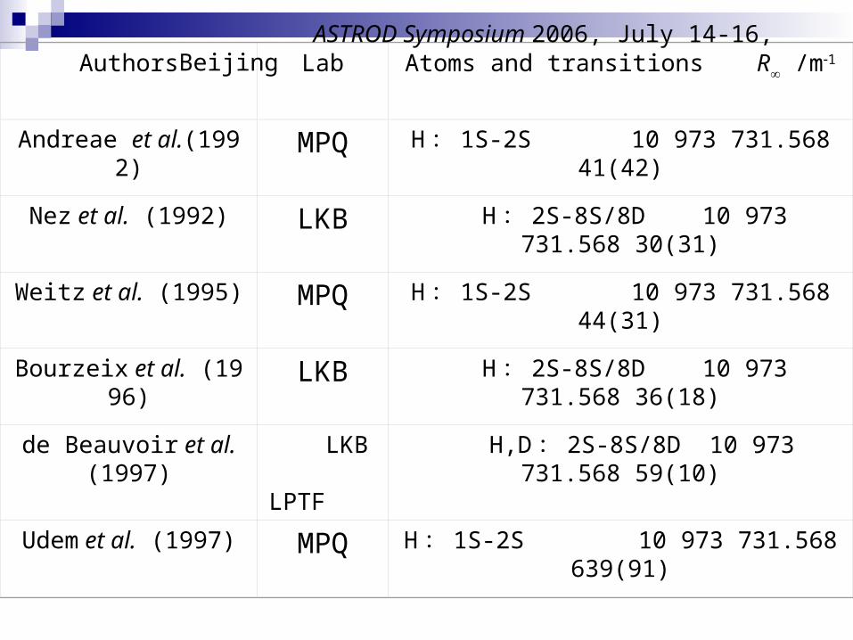
Authors Lab Atoms and transitions R /m1
Andreae et al.(1992) MPQ H : 1S-2S 10 973 731.568 41(42)
Nez et al. (1992) LKB H : 2S-8S/8D 10 973 731.568 30(31)
Weitz et al. (1995) MPQ H : 1S-2S 10 973 731.568 44(31)
Bourzeix et al. (1996) LKB H : 2S-8S/8D 10 973 731.568 36(18)
de Beauvoir et al. (1997)
LKB LPTF
H,D : 2S-8S/8D 10 973 731.568 59(10)
Udem et al. (1997) MPQ H : 1S-2S 10 973 731.568 639(91)
ASTROD Symposium 2006, July 14-16, Beijing
F
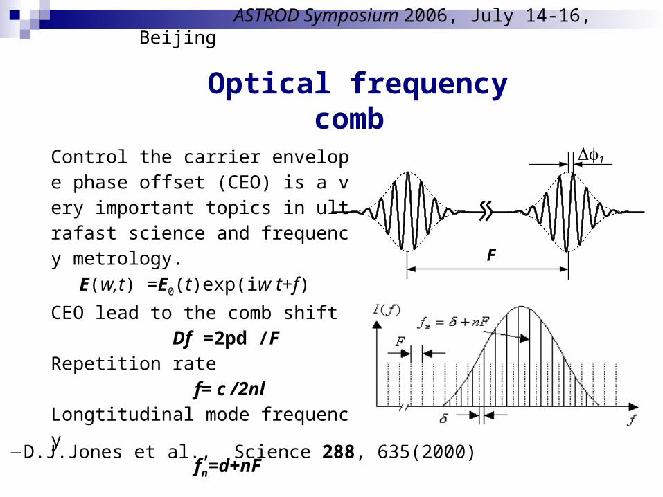
1 Control the carrier envelope phase offset (CEO) is a very important topics in ultrafast science and frequency metrology.
E(w,t) =E0(t)exp(iw t+f)
CEO lead to the comb shift Df =2pd /F Repetition rate f= c /2nlLongtitudinal mode frequency
fn=d+nF
Optical frequency comb
D.J.Jones et al., Science 288, 635(2000)
ASTROD Symposium 2006, July 14-16, Beijing
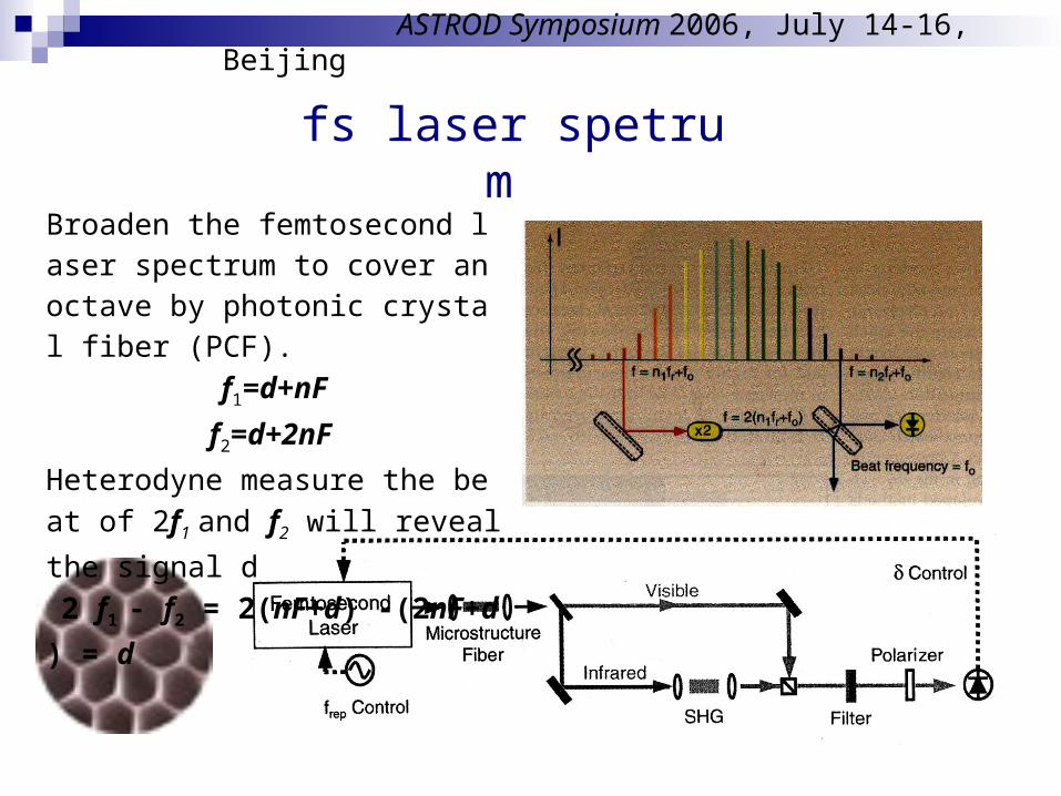
fs laser spetrum
Broaden the femtosecond laser spectrum to cover an octave by photonic crystal fiber (PCF).
f1=d+nF
f2=d+2nF
Heterodyne measure the beat of 2f1 an
d f2 will reveal the signal d
2 f1 - f2 = 2(nF+d) -(2nF+d ) = d
ASTROD Symposium 2006, July 14-16, Beijing
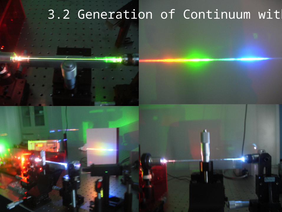
3.2 Generation of Continuum with PCF

Frequency Measurement Experimental Layoutantenna
PumpLaser
PCF
Reference 10MHzP
hase
loop
for re
petitio
n
rate
Phase
loop fo
r C
EO
Grating
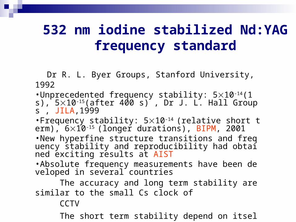
532 nm iodine stabilized Nd:YAGfrequency standard
Dr R. L. Byer Groups, Stanford University, 1992•Unprecedented frequency stability: 510-14(1 s), 510-15(after 400 s) , Dr J. L. Hall Groups , JILA,1999•Frequency stability: 510-14 (relative short term), 610-15 (longer durations), BIPM, 2001•New hyperfine structure transitions and frequency stability and reproducibility had obtained exciting results at AIST•Absolute frequency measurements have been developed in several countries The accuracy and long term stability are similar to the small Cs clock of CCTV
The short term stability depend on itself
Specifications Refer to the small Cs clock (HP-5071
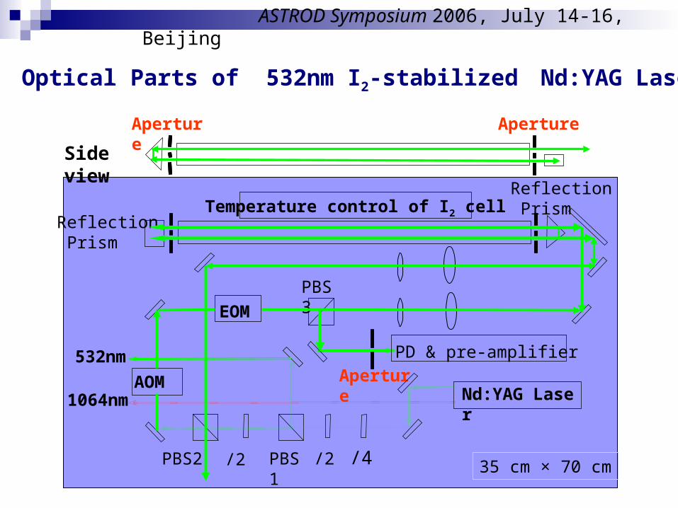
Optical Parts of 532nm I2-stabilized Nd:YAG Laser
532nm
1064nm
Reflection Prism
Reflection Prism
ApertureAOM
EOM
PD & pre-amplifier
Nd:YAG Laser
PBS1 /4/2 /2PBS2
PBS3
Temperature control of I2 cell
Side view
ApertureAperture
35 cm × 70 cm
ASTROD Symposium 2006, July 14-16, Beijing
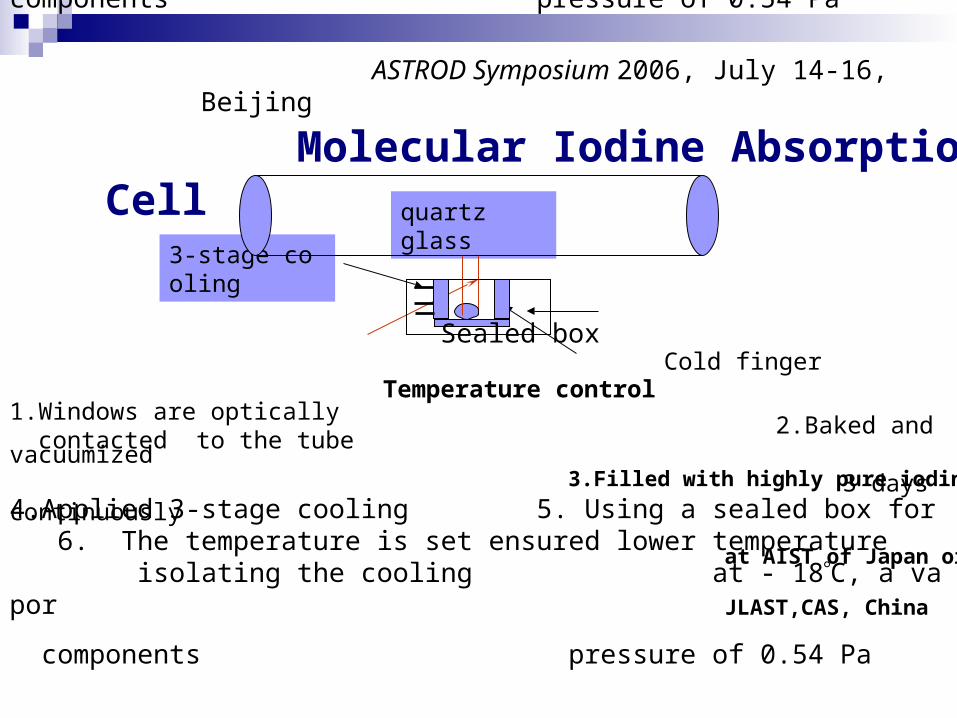
Molecular Iodine Absorption Cell
3-stage cooling
quartz glass
Temperature control Cold finger
Sealed box
1.Windows are optically contacted to the tube
2.Baked and vacuumized 3 days continuously
3.Filled with highly pure iodine at AIST of Japan or JLAST,CAS, China
4.Applied 3-stage cooling 5. Using a sealed box for 6. The temperature is set ensured lower temperature isolating the cooling at - 18C, a vapor components pressure of 0.54 Pa
ASTROD Symposium 2006, July 14-16, Beijing
4.Applied 3-stage cooling 5. Using a sealed box for 6. The temperature is set ensured lower temperature isolating the cooling at - 18C, a vapor
components pressure of 0.54 Pa
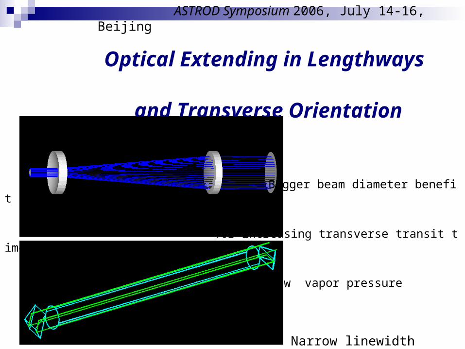
Optical Extending in Lengthways and Transverse Orientation
Bigger beam diameter benefit
for increasing transverse transit time
Low vapor pressure
Narrow linewidth
Good SNR
ASTROD Symposium 2006, July 14-16, Beijing
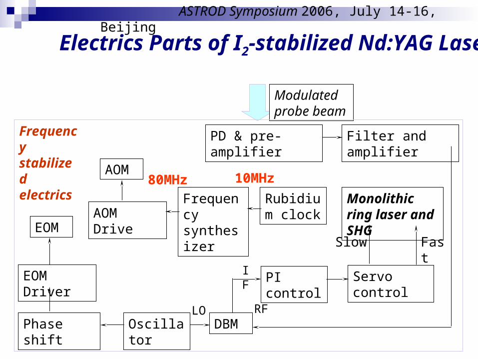
Electrics Parts of I2-stabilized Nd:YAG Laser
Modulated probe beam
Monolithic ring laser and SHG
PD & pre-amplifier Filter and amplifier
Servo control
Slow Fast
PI control
DBMOscillatorPhase shift
EOM Driver
EOM
AOM
AOM DriveFrequency synthesizer
Rubidium clock
RFLO
IF
10MHz80MHz
Frequency stabilized electrics
ASTROD Symposium 2006, July 14-16, Beijing
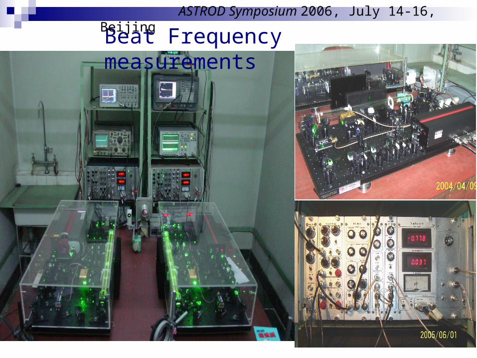
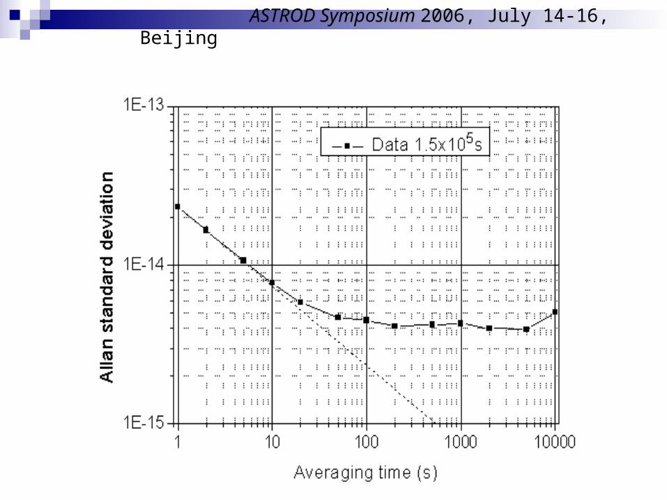
Beat Frequency measurements ASTROD Symposium 2006, July 14-16, Beijing
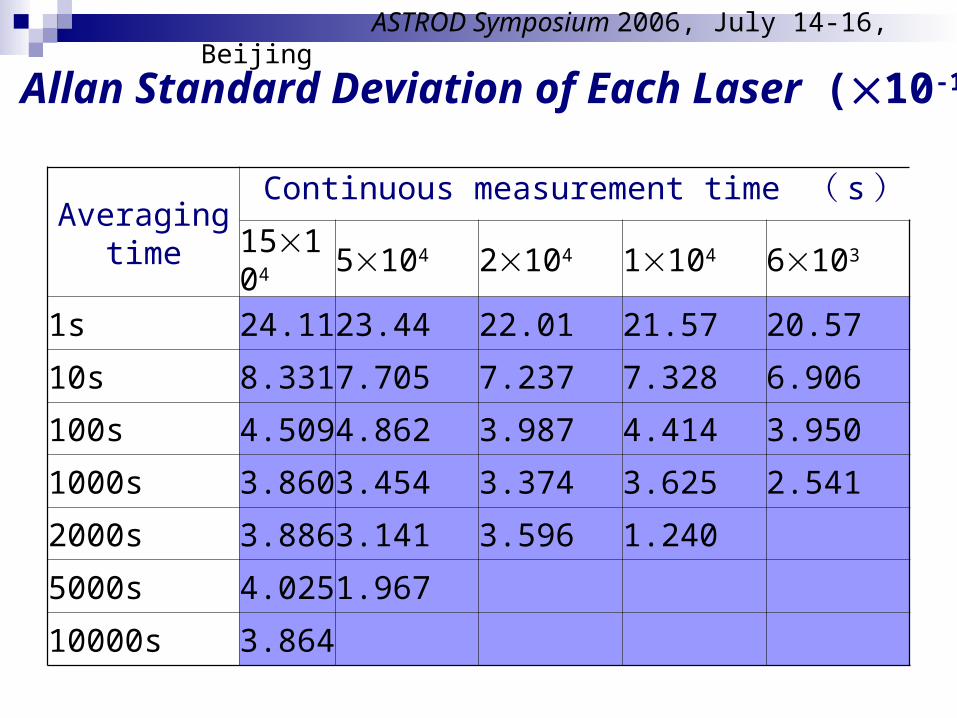
Allan Standard Deviation of Each Laser (10-15 )
Averaging time
Continuous measurement time ( s)15104 5104 2104 1104 6103
1s 24.11 23.44 22.01 21.57 20.57
10s 8.331 7.705 7.237 7.328 6.906
100s 4.509 4.862 3.987 4.414 3.950
1000s 3.860 3.454 3.374 3.625 2.541
2000s 3.886 3.141 3.596 1.240
5000s 4.025 1.967
10000s 3.864
ASTROD Symposium 2006, July 14-16, Beijing
ASTROD Symposium 2006, July 14-16, Beijing
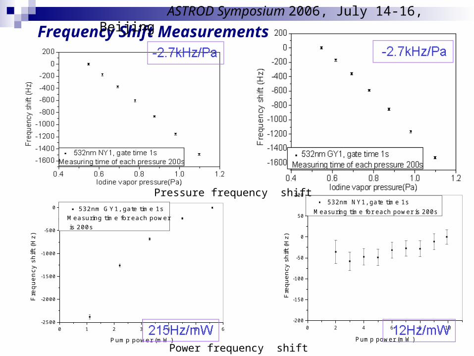
Frequency Shift Measurements
0 1 2 3 4 5 6-2500
-2000
-1500
-1000
-500
0
Fre
qu
en
cy s
hift
(H
z)
Pump power (mW)
532nm GY1, gate time 1sMeasuring time for each power is 200s
0 2 4 6 8 10-200
-150
-100
-50
0
50
100
Fre
quen
cy s
hift
(Hz)
Pump power (mW)
532nm NY1, gate time 1sMeasuring time for each power is 200s
Pressure frequency shift
Power frequency shift
ASTROD Symposium 2006, July 14-16, Beijing
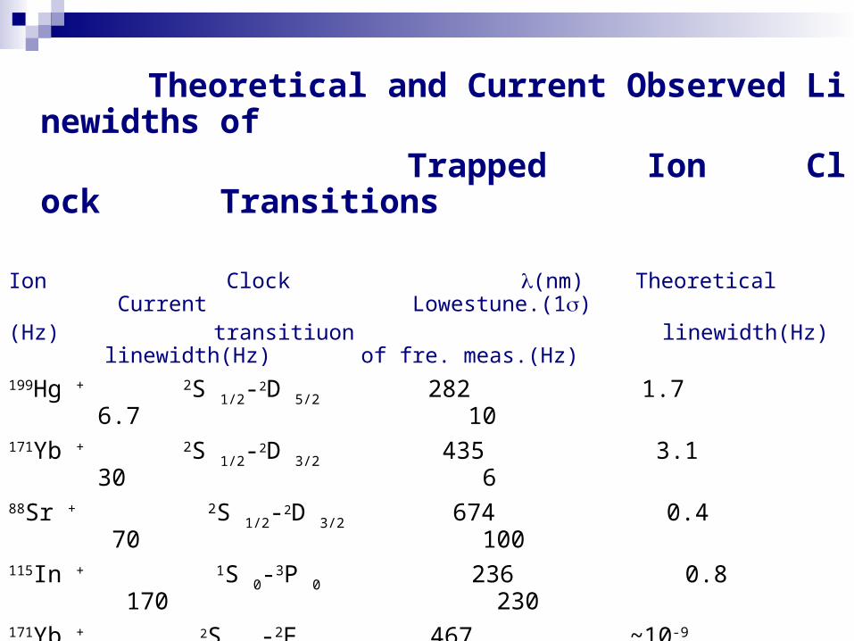
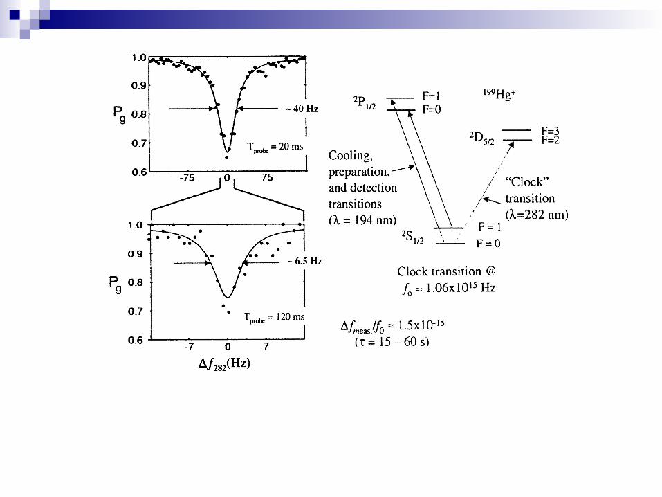
Theoretical and Current Observed Linewidths of Trapped Ion Clock Transitions
Ion Clock (nm) Theoretical Current Lowestune.(1)
(Hz) transitiuon linewidth(Hz) linewidth(Hz) of fre. meas.(Hz)
199Hg + 2S 1/2-2D 5/2 282 1.7 6.7 10
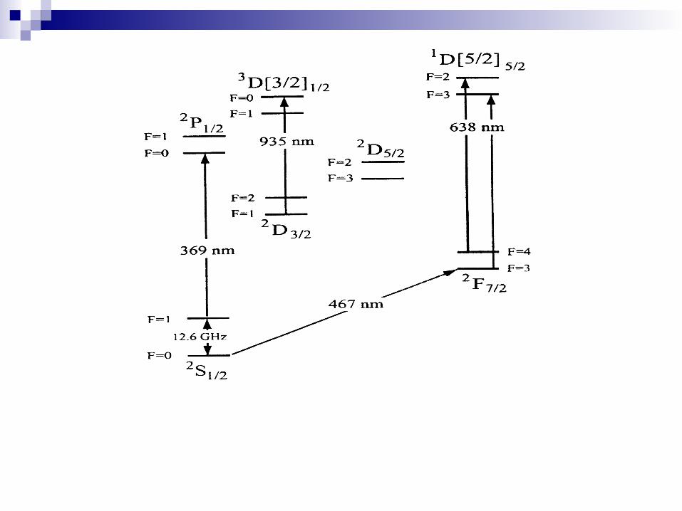
171Yb + 2S 1/2-2D 3/2 435 3.1 30 6
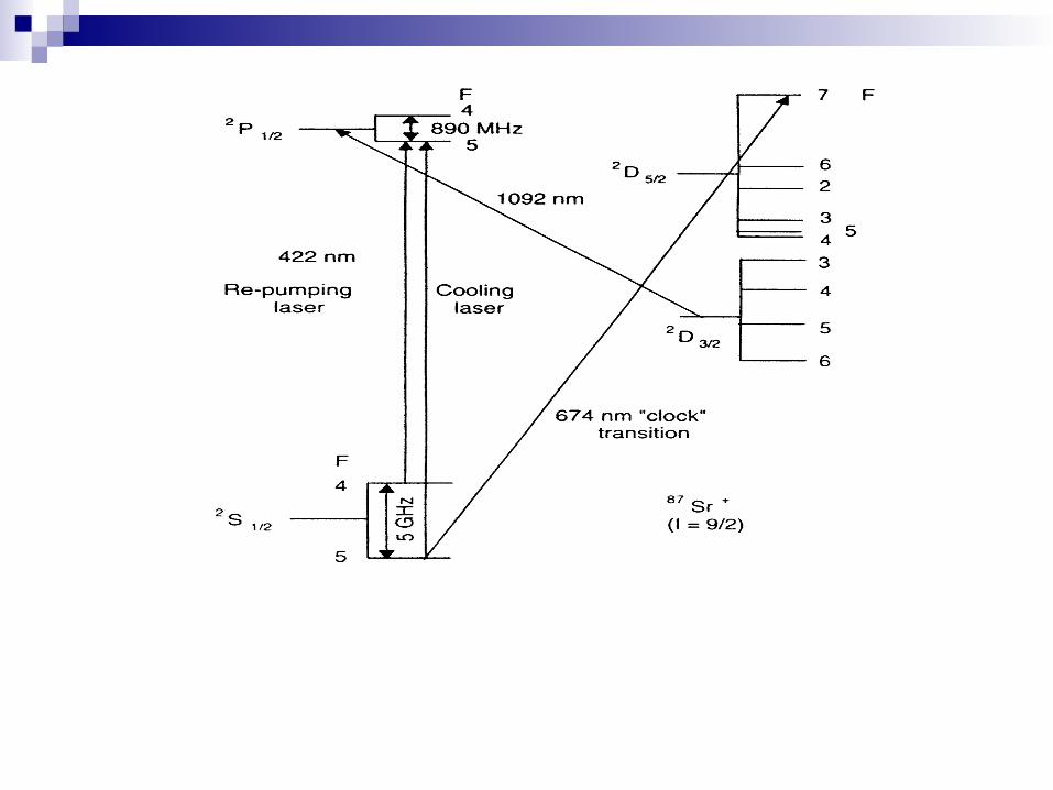
88Sr + 2S 1/2-2D 3/2 674 0.4 70 100
115In + 1S 0-3P 0 236 0.8 170 230
171Yb + 2S 1/2-2F 7/2 467 ~10-9 180 230
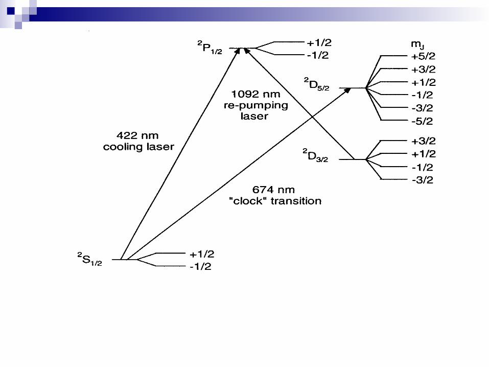
40Ca + 2S 1/2- 2D5/2 729 0.2 1000
• Frequency value of 40Ca + was not recommended by CIPM as reference for the
• Realization of the meter
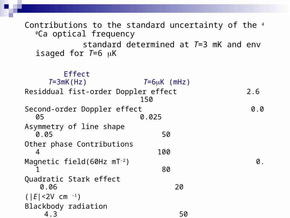
Contributions to the standard uncertainty of the 40Ca optical frequency
standard determined at T=3 mK and envisaged for T=6 K
Effect T=3mK(Hz) T=6K (mHz)Residdual fist-order Doppler effect 2.6 150Second-order Doppler effect 0.005 0.025 Asymmetry of line shape 0.05 50Other phase Contributions 4 100Magnetic field(60Hz mT-2) 0.1 80Quadratic Stark effect 0.06 20(|E|<2V cm -1) Blackbody radiation 4.3 50Servo electronics 3.2 100Influence of cold atom coll 1.8 260Statistical uncertainty of 3 <5frequency comparison Total uncertainty 8 350Total relative uncertainty / 2 10 –14 8 10 -16
ASTROD Symposium 2006, July 14-16, Beijing
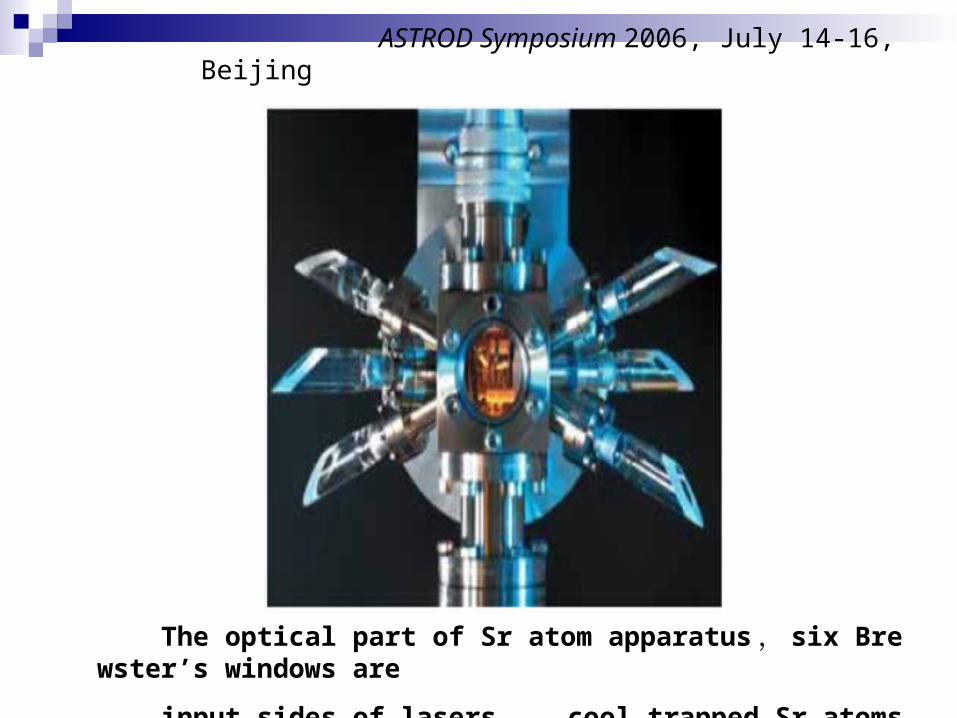
The optical part of Sr atom apparatus , six Brewster’s windows are
input sides of lasers , cool trapped Sr atoms are in the center part
Developing Definition of Second and Frequency Standards
Cold atom microwave frequency standards: Cs,Rb Optical cold atom frequency standards : Ca, Mg, Sr Ion frequency standards : : 199Hg +,115In + ,88Sr + , 87Sr + , 171Yb + ,Ca +
CIPM – CCTF adopted a 2001resolution to seek secondary ‘representations’ of the second. Such representations can be based on
the different cold ion and atom standards ,both optical and microwave, and would be able to take full advantage of improved stability and reproducibility, but remain limited to the caesium accuracy. This position represents a useful intermediate stage for evaluating the systematics of different systems prior to making any rational choice for a new time definition.
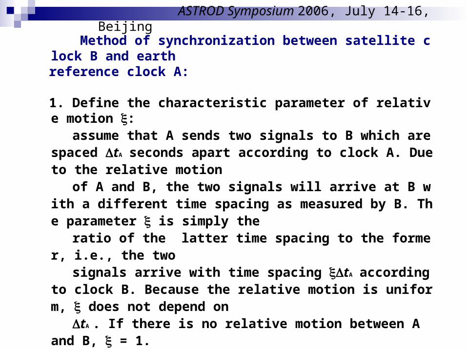
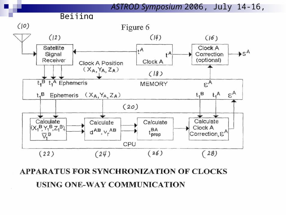
Method of synchronization between satellite clock B and earth reference clock A:
1. Define the characteristic parameter of relative motion : assume that A sends two signals to B which are spaced tA seconds ap
art according to clock A. Due to the relative motion of A and B, the two signals will arrive at B with a different time spaci
ng as measured by B. The parameter is simply the ratio of the latter time spacing to the former, i.e., the two signals arrive with time spacing tA according to clock B. Because th
e relative motion is uniform, does not depend on tA . If there is no relative motion between A and B, = 1.
2. If B sends two signals to A which are spaced tB seconds apart accor
ding to clock B. According relativity principle, the two signals will arrive at A with time spacing tB as measured by A. From the definiti
on of given above, we see that = (t2B – t1B )/(t2A – t1A ) = (t3A – t2A )/(t2B – t1B )
=[(t3A – t2A )/(t2A – t1A )]1/2
ASTROD Symposium 2006, July 14-16, Beijing
Without Locking Locking
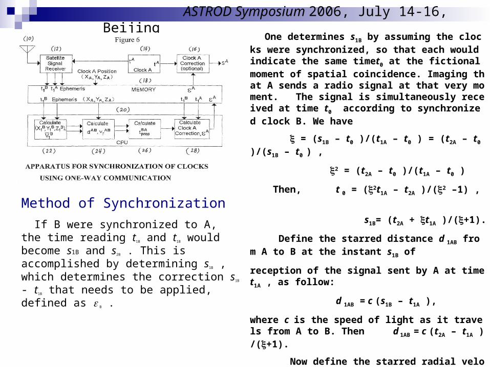
Method of Synchronization
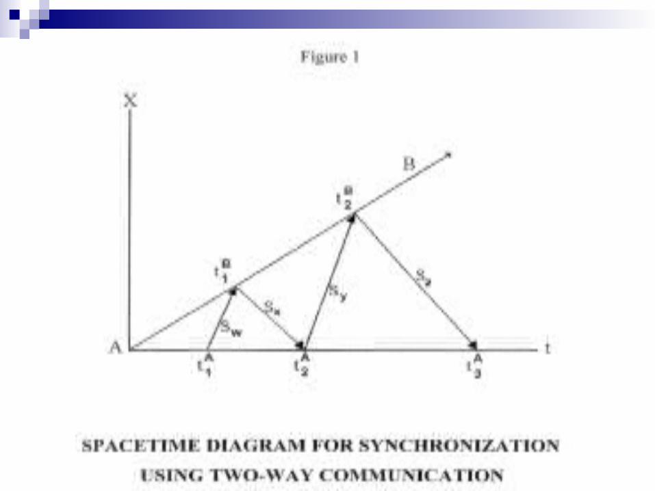
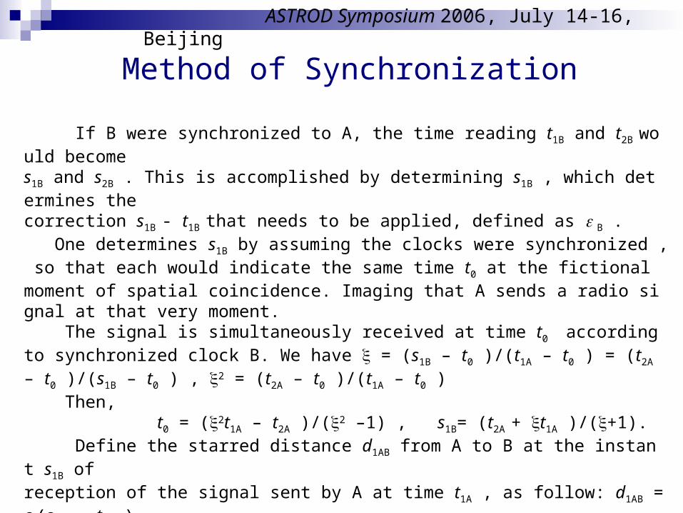
If B were synchronized to A, the time reading t1B and t2B would becomes1B and s2B . This is accomplished by determining s1B , which determines the correction s1B - t1B that needs to be applied, defined as B . One determines s1B by assuming the clocks were synchronized , so that each would indicate the same time t0 at the fictional moment of spatial coincidence. Imaging that A sends a radio signal at that very moment. The signal is simultaneously received at time t0 according to synchronized clock B. We have = (s1B – t0 )/(t1A – t0 ) = (t2A – t0 )/(s1B – t0 ) , 2 = (t2A – t0 )/(t1A – t0 ) Then, t0 = (2t1A – t2A )/(2 –1) , s1B= (t2A + t1A )/(+1). Define the starred distance d1AB from A to B at the instant s1B of reception of the signal sent by A at time t1A , as follow: d1AB = c (s1B – t1A ), where c is the speed of light as it travels from A to B. Then d1AB = c (t2A – t1A )/(+1). Now define the starred radial velocity vrAB between A and B as follow: vrAB =d1AB/s1B = [c (t2A –t1A )/(+1)]/[(t2A + t1A )/(+1)] =c (t2A–t1A)/(t2A+t1A) = c (-1)/.
ASTROD Symposium 2006, July 14-16, Beijing
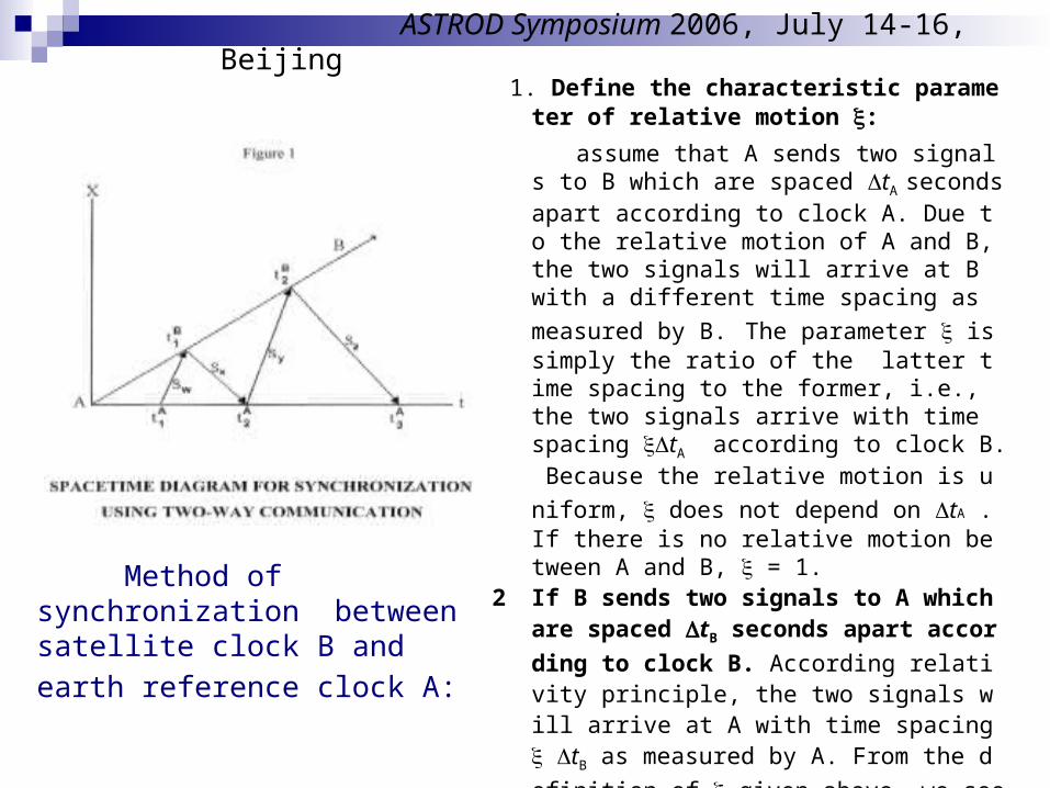
1. Define the characteristic parameter of relative
motion :
assume that A sends two signals to B which are spaced tA seconds apart according to clock A. Due to the relative motion of A and B, the two signals will arrive at B with a different time spacing as me
asured by B. The parameter is simply the ratio of the latter time spacing to the former, i.e., the two signals arrive with time spacing tA according to clock B. Because the relative motion is uniform,
does not depend on tA . If there is no relative motion between A and B, = 1.
2 If B sends two signals to A which are spaced tB
seconds apart according to clock B. According relativity principle, the two signals will arrive at A with time spacing tB as measured by A. From t
he definition of given above, we see that = (t2B – t1B )/(t2A – t1A )
= (t3A – t2A )/(t2A – t1A )
=[(t3A – t2A )/(t2A – t1A )]1/2
ASTROD Symposium 2006, July 14-16, Beijing
Method of synchronization between satellite clock B and earth
reference clock A:
ASTROD Symposium 2006, July 14-16, Beijing
ASTROD Symposium 2006, July 14-16, Beijing
Method of Synchronization
If B were synchronized to A, the time reading t1B and t1B would become s1B and s2B . This is accomplished by determining s1B , which determines the correction s1B - t1B that needs to be applied, defined as B .
One determines s1B by assuming the clocks were synchronized, so that each would indicate the same timet0 at the fictional moment of spatial coincidence. Imaging that A sends a radio signal at that very moment. The signal is simultaneously received at time t0 according to synchronized clock B. We have
= (s1B – t0 )/(t1A – t0 ) = (t2A – t0 )/(s1B – t0 ) ,
2 = (t2A – t0 )/(t1A – t0 )
Then, t 0 = (2t1A – t2A )/(2 –1) ,
s1B= (t2A + t1A )/(+1).
Define the starred distance d 1AB from A to B at the instant s1B of
reception of the signal sent by A at time t1A , as follow:
d 1AB = c (s1B – t1A ),
where c is the speed of light as it travels from A to B. Then d 1AB = c (t2A – t1A )/(+1).
Now define the starred radial velocity v rAB between A and B as follow:
v rAB =d 1AB/s 1B = [c (t2A –t1A )/(+1)]/[(t2A + t1A )/(+1)]
= c (t2A–t1A)/(t2A+t1A) = c (-1)/.
The End
Thank you for your attention!
ASTROD Symposium 2006, July 14-16, Beijing