
Technical Specification - 株式会社QT · 3GPP TS 25.413 V1.3.1 (1999-09) Technical Specification...
57
3GPP TS 25.413 V1.3.1 (1999-09) Technical Specification 3 rd Generation Partnership Project (3GPP); Technical Specification Group (TSG) RAN UTRAN Iu Interface RANAP Signalling [UMTS 25.413] <
-
Upload
truongquynh -
Category
Documents
-
view
228 -
download
0
Transcript of Technical Specification - 株式会社QT · 3GPP TS 25.413 V1.3.1 (1999-09) Technical Specification...
3GPP
TS 25.413 V1.3.1 (1999-09)Technical Specification
3rd Generation Partnership Project (3GPP);Technical Specification Group (TSG) RAN
UTRAN Iu Interface RANAP Signalling
[UMTS 25.413]
<
3GPP
TS 25.413 V1.3.1 (1999-09)2[UMTS 25.413]
Reference <Workitem> (<Shortfilename>.PDF)
Keywords <keyword[, keyword]>
3GPP
Postal address
Office address
Internet [email protected]
Individual copies of this deliverable can be downloaded from http://www.3gpp.org
Copyright Notification
No part may be reproduced except as authorized by written permission. The copyright and the foregoing restriction extend to reproduction in all media.
©
All rights reserved.
3GPP
TS 25.413 V1.3.1 (1999-09)3[UMTS 25.413]
Contents
Intellectual Property Rights.......................................................................................................................7
Foreword ................................................................................................................................................7
1 Scope ............................................................................................................................................7
2 References ....................................................................................................................................7
3 Definitions and abbreviations ...........................................................................................................8 3.1 Definitions............................................................................................................................................................................. 8 3.2 Abbreviations....................................................................................................................................................................... 9
4 General..........................................................................................................................................9
5 RANAP Services...........................................................................................................................9
6 Services expected from signalling transport ....................................................................................10
7 Functions of RANAP...................................................................................................................10
8 RANAP procedures.....................................................................................................................11 8.1 Elementary Procedures...................................................................................................................................................... 11 8.2 Radio Access Bearer Assignment................................................................................................................................... 12 8.2.1 Normal operation ......................................................................................................................................................... 12 8.2.2 Abnormal conditions .................................................................................................................................................. 14 8.3 RAB Release Request....................................................................................................................................................... 15 8.4 Iu Release Request ............................................................................................................................................................ 15 8.5 Iu Release............................................................................................................................................................................ 15 8.5.1 Normal operation ......................................................................................................................................................... 15 8.5.2 Abnormal conditions .................................................................................................................................................. 16 8.6 Relocation ........................................................................................................................................................................... 16 8.6.1 General........................................................................................................................................................................... 16 8.6.2 Relocation Preparation................................................................................................................................................ 17 8.6.2.1 Successful operation ............................................................................................................................................ 17 8.6.2.2 Unsuccessful operation ....................................................................................................................................... 17 8.6.2.3 Abnormal conditions............................................................................................................................................ 18 8.6.2.4 Relocation co-ordination in source RNC........................................................................................................... 18 8.6.2.5 Interactions with other RANAP procedures..................................................................................................... 18 8.6.3 Relocation resource allocation .................................................................................................................................. 19 8.6.3.1 Successful operation ............................................................................................................................................ 19 8.6.3.2 Unsuccessful operation ....................................................................................................................................... 19 8.6.3.3 Abnormal conditions............................................................................................................................................ 20 8.6.3.4 Relocation co-ordination in target RNC............................................................................................................. 21 8.6.4 Relocation Detect ........................................................................................................................................................ 21 8.6.4.1 Normal operation................................................................................................................................................... 21 8.6.4.2 Abnormal conditions............................................................................................................................................ 21 8.6.5 Relocation Complete ................................................................................................................................................... 22 8.6.5.1 Normal operation................................................................................................................................................... 22 8.6.5.2 Unsuccessful operation ....................................................................................................................................... 22 8.6.6 Relocation Cancel........................................................................................................................................................ 23 8.7 SRNS Context Transfer..................................................................................................................................................... 23 8.8 Paging.................................................................................................................................................................................. 24 8.9 Common Id .......................................................................................................................................................................... 24 8.10 CN Invoke Trace ................................................................................................................................................................ 25 8.11 Security Mode Control...................................................................................................................................................... 25 8.11.1 Successful operation................................................................................................................................................... 25 8.11.2 Unsuccessful operation.............................................................................................................................................. 26 8.12 Location Reporting Control.............................................................................................................................................. 27 8.12.1 Normal operation ......................................................................................................................................................... 27
3GPP
TS 25.413 V1.3.1 (1999-09)4[UMTS 25.413]
8.12.2 Abnormal conditions .................................................................................................................................................. 27 8.12.2.1 Abnormal conditions in RNC .............................................................................................................................. 27 8.13 Location Report.................................................................................................................................................................. 28 8.13.1 Successful operation................................................................................................................................................... 28 8.13.2 Unsuccessful operation.............................................................................................................................................. 28 8.13.3 Abnormal conditions .................................................................................................................................................. 28 8.13.3.1 Abnormal conditions in CN................................................................................................................................. 28 8.14 Data Volume Report........................................................................................................................................................... 28 8.15 Initial UE Message............................................................................................................................................................. 29 8.16 Direct Transfer.................................................................................................................................................................... 29 8.17 CN Information Broadcast................................................................................................................................................ 30 8.18 Overload Control................................................................................................................................................................ 31 8.18.1 General........................................................................................................................................................................... 31 8.18.2 Philosophy.................................................................................................................................................................... 31 8.18.3 Overload at the CN...................................................................................................................................................... 31 8.18.4 Overload at the UTRAN............................................................................................................................................. 32 8.19 Reset .................................................................................................................................................................................... 32 8.19.1 General........................................................................................................................................................................... 32 8.19.2 Reset at the UTRAN................................................................................................................................................... 32 8.19.3 Reset at the CN ............................................................................................................................................................ 33 8.19.4 Abnormal Conditions.................................................................................................................................................. 33 8.19.4.1 Abnormal Condition at the UTRAN................................................................................................................... 33 8.19.4.2 Abnormal Condition at the CN............................................................................................................................ 33 8.19.4.3 Crossing of Reset messages................................................................................................................................ 33 8.20 Error Indication................................................................................................................................................................... 34 8.20.1 General........................................................................................................................................................................... 34 8.20.2 CN originated Error Indication................................................................................................................................... 34 8.20.3 RNC originated Error Indication................................................................................................................................ 34
9 Elements for RANAP communication ...........................................................................................35 9.1 Message contents ............................................................................................................................................................. 35 9.1.1 RAB ASSIGNMENT REQUEST................................................................................................................................ 35 9.1.2 RAB ASSIGNMENT RESPONSE.............................................................................................................................. 36 9.1.3 RAB RELEASE REQUEST......................................................................................................................................... 37 9.1.4 IU RELEASE REQUEST.............................................................................................................................................. 37 9.1.5 IU RELEASE COMMAND......................................................................................................................................... 37 9.1.6 IU RELEASE COMPLETE.......................................................................................................................................... 38 9.1.7 RELOCATION REQUIRED ........................................................................................................................................ 38 9.1.8 RELOCATION REQUEST.......................................................................................................................................... 38 9.1.9 RELOCATION REQUEST ACKNOWLEDGE......................................................................................................... 39 9.1.10 RELOCATION COMMAND...................................................................................................................................... 39 9.1.11 RELOCATION DETECT............................................................................................................................................. 39 9.1.12 RELOCATION COMPLETE....................................................................................................................................... 39 9.1.13 RELOCATION PREPARATION FAILURE ............................................................................................................. 40 9.1.14 RELOCATION FAILURE........................................................................................................................................... 40 9.1.15 RELOCATION CANCEL............................................................................................................................................ 40 9.1.16 RELOCATION CANCEL ACKNOWLEDGE........................................................................................................... 40 9.1.17 SRNS CONTEXT REQUEST...................................................................................................................................... 40 9.1.18 SRNS CONTEXT RESPONSE.................................................................................................................................... 41 9.1.19 PAGING......................................................................................................................................................................... 41 9.1.20 COMMON ID............................................................................................................................................................... 41 9.1.21 CN INVOKE TRACE................................................................................................................................................... 41 9.1.22 SECURITY MODE COMMAND............................................................................................................................... 42 9.1.23 SECURITY MODE COMPLETE................................................................................................................................ 42 9.1.24 SECURITY MODE REJECT........................................................................................................................................ 42 9.1.25 LOCATION REPORTING CONTROL....................................................................................................................... 42 9.1.26 LOCATION REPORT.................................................................................................................................................. 42 9.1.27 DATA VOLUME REPORT REQUEST..................................................................................................................... 43 9.1.28 DATA VOLUME REPORT......................................................................................................................................... 43
3GPP
TS 25.413 V1.3.1 (1999-09)5[UMTS 25.413]
9.1.29 INITIAL UE MESSAGE.............................................................................................................................................. 43 9.1.30 DIRECT TRANSFER................................................................................................................................................... 43 9.1.31 CN INFORMATION BROADCAST REQUEST...................................................................................................... 44 9.1.32 CN INFORMATION BROADCAST CONFIRM ..................................................................................................... 44 9.1.33 CN INFORMATION BROADCAST REJECT.......................................................................................................... 44 9.1.34 OVERLOAD.................................................................................................................................................................. 44 9.1.35 RESET............................................................................................................................................................................ 44 9.1.36 RESET ACKNOWLEDGE........................................................................................................................................... 45 9.1.37 ERROR INDICATION................................................................................................................................................. 45 9.2 Information element definitions....................................................................................................................................... 45 9.2.1 Radio network layer related IEs ................................................................................................................................. 45 9.2.1.1 Message Type ....................................................................................................................................................... 45 9.2.1.2 RAB ID.................................................................................................................................................................... 45 9.2.1.3 RAB parameters..................................................................................................................................................... 45 9.2.1.4 Cause....................................................................................................................................................................... 45 9.2.1.5 Priority level, queuing and pre-emption indication.......................................................................................... 45 9.2.1.6 RAB linking............................................................................................................................................................ 46 9.2.1.7 CN Domain Indicator............................................................................................................................................ 46 9.2.1.8 Trace Type ............................................................................................................................................................. 46 9.2.1.9 Trigger ID ............................................................................................................................................................... 46 9.2.1.10 Trace Reference..................................................................................................................................................... 46 9.2.1.11 UE Identity ............................................................................................................................................................. 46 9.2.1.12 OMC ID................................................................................................................................................................... 46 9.2.1.13 Integrity Protection Information ......................................................................................................................... 46 9.2.1.14 Encryption Information ........................................................................................................................................ 46 9.2.1.15 UE Classmark ......................................................................................................................................................... 46 9.2.1.16 Chosen Integrity Protection Algorithm............................................................................................................. 46 9.2.1.17 Chosen Encryption Algorithm............................................................................................................................ 46 9.2.1.18 Broadcast Area...................................................................................................................................................... 46 9.2.1.19 Categorisation parameters ................................................................................................................................... 47 9.2.1.20 Request Type......................................................................................................................................................... 47 9.2.1.21 Data Volume Reporting Indication ..................................................................................................................... 47 9.2.1.22 User Plane Mode................................................................................................................................................... 47 9.2.1.23 Paging Area ID ...................................................................................................................................................... 47 9.2.1.24 Non Searching Indication .................................................................................................................................... 47 9.2.1.25 Source ID................................................................................................................................................................ 47 9.2.1.26 Target ID................................................................................................................................................................. 47 9.2.1.27 Source RNC to Target RNC Transparent Container........................................................................................ 47 9.2.1.28 Target RNC to Source RNC Transparent Container........................................................................................ 47 9.2.1.29 Number of steps .................................................................................................................................................... 47 9.2.1.30 DL GTP-PDU Sequence Number......................................................................................................................... 48 9.2.1.31 UL GTP-PDU Sequence Number......................................................................................................................... 48 9.2.1.32 UL RLC-PDU Sequence Number......................................................................................................................... 48 9.2.1.33 DL RLC-PDU Sequence Number......................................................................................................................... 48 9.2.2 Transport network layer related IEs .......................................................................................................................... 48 9.2.2.1 Transport address ................................................................................................................................................. 48 9.2.2.2 Iu transport association ....................................................................................................................................... 48 9.2.3 NAS related IEs ............................................................................................................................................................ 48 9.2.3.1 NAS Binding Information .................................................................................................................................... 48 9.2.3.2 Permanent NAS Identity ...................................................................................................................................... 48 9.2.3.3 Temporary UE ID................................................................................................................................................... 48 9.2.3.4 Paging Cause......................................................................................................................................................... 48 9.2.3.5 NAS Broadcast Information ................................................................................................................................ 49 9.2.3.6 NAS PDU................................................................................................................................................................ 49 9.2.3.7 LAI........................................................................................................................................................................... 49 9.2.3.8 RAC......................................................................................................................................................................... 49 9.2.3.9 Area Identity Code................................................................................................................................................ 49 9.2.3.10 Transmitted Data Volume..................................................................................................................................... 49 9.3 Message and Information element abstract syntax (with ASN.1).............................................................................. 49
3GPP
TS 25.413 V1.3.1 (1999-09)6[UMTS 25.413]
9.4 Message transfer syntax................................................................................................................................................... 52 9.5 Timers .................................................................................................................................................................................. 52
10 Handling of unknown, unforeseen and erroneous protocol data ........................................................53
11 Annex A (normative):...................................................................................................................53 Annex B Document Stability Assessment Table .......................................................................................................................... 53
12 History ........................................................................................................................................53
3GPP
TS 25.413 V1.3.1 (1999-09)7[UMTS 25.413]
Intellectual Property Rights
Foreword This Technical Specification has been produced by the 3rd Generation Partnership Project, Technical Specification Group <TSG name>.
The contents of this TS may be subject to continuing work within the 3GPP and may change following formal TSG approval. Should the TSG modify the contents of this TS, it will be re-released with an identifying change of release date and an increase in version number as follows:
Version m.t.e
where:
m indicates [major version number]
x the second digit is incremented for all changes of substance, i.e. technical enhancements, corrections, updates, etc.
y the third digit is incremented when editorial only changes have been incorporated into the specification.
1 Scope This document specifies the radio network layer signalling protocol called Radio Access Network Application Part (RANAP) for the Iu interface. RANAP supports the functions of Iu interface by signalling procedures defined in this document. RANAP is developed in accordance to the general principles stated in [1], [2] and [3].
2 References [Editor's note: To be updated.]
The following documents contain provisions which, through reference in this text, constitute provisions of the present document.
• References are either specific (identified by date of publication, edition number, version number, etc.) or non-specific.
• For a specific reference, subsequent revisions do not apply.
• For a non-specific reference, the latest version applies.
• A non-specific reference to an ETS shall also be taken to refer to later versions published as an EN with the same number.
[1] UMTS 23.930, Iu Principles
[2] UMTS 25.410, UTRAN Iu Interface; General Aspects and Principles
[3] UMTS 25.401, UTRAN Overall Description
[4] UMTS 25.931, UTRAN Functions, Examples on Signalling Procedures
[5] UMTS 25.412, UTRAN Iu Interface Signalling Transport
3GPP
TS 25.413 V1.3.1 (1999-09)8[UMTS 25.413]
[6] UMTS 25.415, Iu Interface CN-UTRAN User Plane Protocol
3 Definitions and abbreviations
3.1 Definitions For the purposes of the present document, the [following] terms and definitions [given in … and the following] apply.
Relocation of SRNS: Relocation of SRNS is a UMTS functionality used to relocate the serving RNS role from one RNS to another RNS. This UMTS functionality is realised by several elementary procedures executed in several interfaces and by several protocols and it may involve a change in the radio resources used between UTRAN and UE.
It is also possible to relocate the serving RNS role from one RNS to another relocation target external to UMTS or functionality equivalent to the serving RNS role from another relocation source external to UMTS to another RNS.
Serving RNS (SRNS): A role an RNS can take with respect to a specific connection between an UE and UTRAN. There is one Serving RNS for each UE that has a connection to UTRAN. The Serving RNS is in charge of the radio connection between a UE and the UTRAN. The Serving RNS terminates the Iu for this UE.
Serving RNC (SRNC): SRNC is the RNC belonging to SRNS.
Source RNS: A role, with respect to a specific connection between UTRAN and CN, that RNS takes when it decides to initiate a relocation of SRNS.
Source RNC: Source RNC is the RNC belonging to source RNS.
Target RNS: A role an RNS gets with respect to a specific connection between UTRAN and CN when it is being a subject of a relocation of SRNS which is being made towards that RNS.
Target RNC: Target RNC is the RNC belonging to target RNS.
Elementary Procedure: The RANAP protocol consists of Elementary Procedures (EPs). An Elementary Procedure is a unit of interaction between the RNS and the CN. An EP consists of an initiating message and possibly a response message. Three kinds of EPs are used:
• Class 1: Elementary Procedures with response (success or failure).
• Class 2: Elementary Procedures without response.
• Class 3: Elementary Procedures with possibility of multiple responses.
For Class 1 EPs, the types of responses can be as follows:
Successful
• A signalling message explicitly indicates that the elementary procedure successfully completed with the receipt of the response.
Unsuccessful
• A signalling message explicitly indicates that the EP failed.
• On time supervision expiry (i.e. absence of expected response).
Class 2 EPs are considered always successful.
3GPP
TS 25.413 V1.3.1 (1999-09)9[UMTS 25.413]
Class 3 EPs have one or several response messages reporting both successful, unsuccessful outcome of the requests and temporary status information about the requests. This type of EP only initiates and terminates through response(s) or EP timer expiry.
The following applies concerning interaction between Elementary Procedures:
• The Reset procedure can interact with all EPs.
• The Iu Release procedure can interact with all EPs except the Reset procedure.
3.2 Abbreviations AAL2 ATM Adaptation Layer type 2 AS Access Stratum ASN.1 Abstract Syntax Notation One ATM Asynchronous Transfer Mode CN Core Network CRNC Controlling RNC CS Circuit Switched DRNC Drift RNC DRNS Drift RNS EP Elementary Procedure MSC Mobile services Switching Center NAS Non Access Stratum PDU Protocol Data Unit PS Packet Switched QoS Quality of Service RAB Radio Access Bearer RNC Radio Network Controller RNS Radio Network Subsystem RANAP Radio Access Network Application Part SCCP Signalling Connection Control Part SGSN Serving GPRS Support Node SRNC Serving RNC SRNS Serving RNS UE User Equipment UTRAN UMTS Terrestrial Radio Access Network
4 General [Editor's note: This chapter should describe requirements on RANAP forward/backward compatibility, error handling principles, message coding principles etc.]
5 RANAP Services [Editor's note: This chapter should describe services of RANAP protocol.]
[Editor's note: It has been agreed that the editor will provide text for this section.]
The RANAP offers the following services:
3GPP
TS 25.413 V1.3.1 (1999-09)10[UMTS 25.413]
6 Services expected from signalling transport [Editor's note: This chapter should describe expected services from signalling transport.]
[Editor's note: It has been agreed that the editor will provide text for this section.]
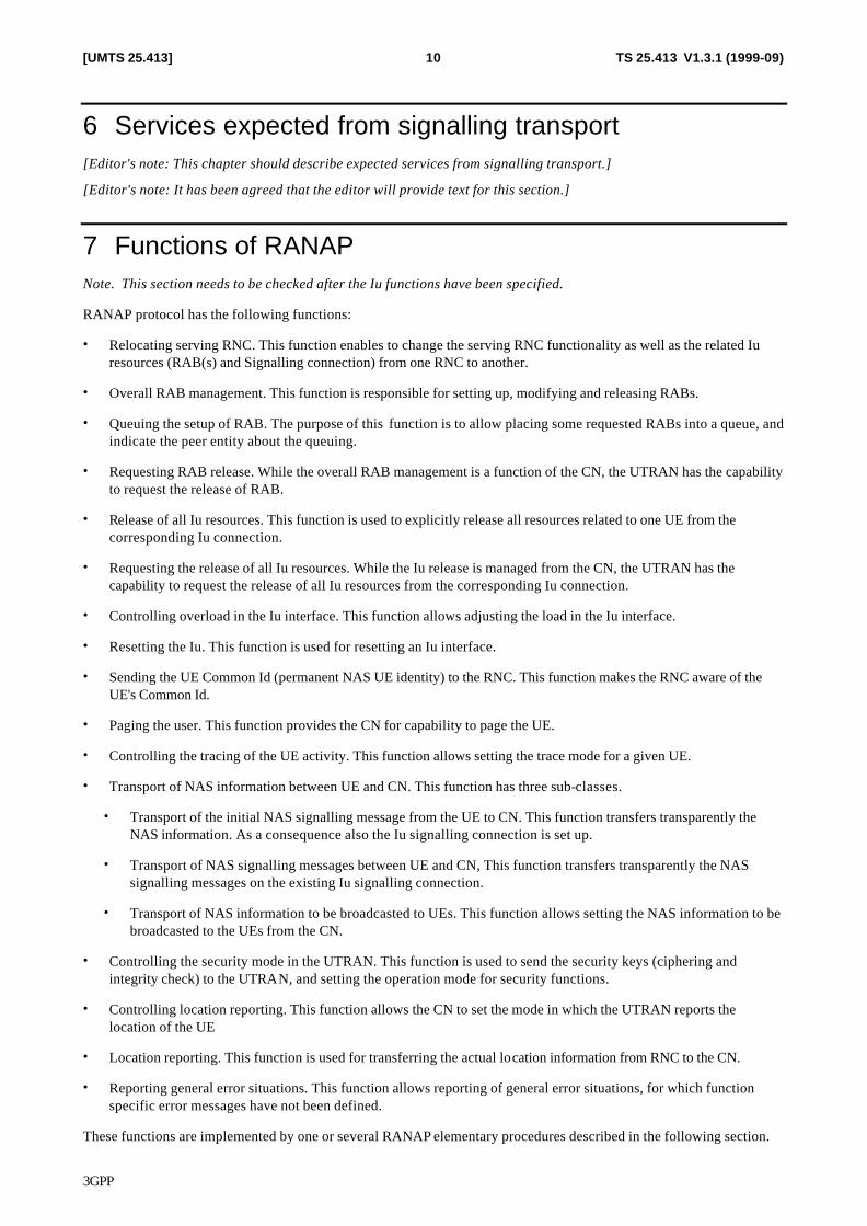
7 Functions of RANAP Note. This section needs to be checked after the Iu functions have been specified.
RANAP protocol has the following functions:
• Relocating serving RNC. This function enables to change the serving RNC functionality as well as the related Iu resources (RAB(s) and Signalling connection) from one RNC to another.
• Overall RAB management. This function is responsible for setting up, modifying and releasing RABs.
• Queuing the setup of RAB. The purpose of this function is to allow placing some requested RABs into a queue, and indicate the peer entity about the queuing.
• Requesting RAB release. While the overall RAB management is a function of the CN, the UTRAN has the capability to request the release of RAB.
• Release of all Iu resources. This function is used to explicitly release all resources related to one UE from the corresponding Iu connection.
• Requesting the release of all Iu resources. While the Iu release is managed from the CN, the UTRAN has the capability to request the release of all Iu resources from the corresponding Iu connection.
• Controlling overload in the Iu interface. This function allows adjusting the load in the Iu interface.
• Resetting the Iu. This function is used for resetting an Iu interface.
• Sending the UE Common Id (permanent NAS UE identity) to the RNC. This function makes the RNC aware of the UE's Common Id.
• Paging the user. This function provides the CN for capability to page the UE.
• Controlling the tracing of the UE activity. This function allows setting the trace mode for a given UE.
• Transport of NAS information between UE and CN. This function has three sub-classes.
• Transport of the initial NAS signalling message from the UE to CN. This function transfers transparently the NAS information. As a consequence also the Iu signalling connection is set up.
• Transport of NAS signalling messages between UE and CN, This function transfers transparently the NAS signalling messages on the existing Iu signalling connection.
• Transport of NAS information to be broadcasted to UEs. This function allows setting the NAS information to be broadcasted to the UEs from the CN.
• Controlling the security mode in the UTRAN. This function is used to send the security keys (ciphering and integrity check) to the UTRAN, and setting the operation mode for security functions.
• Controlling location reporting. This function allows the CN to set the mode in which the UTRAN reports the location of the UE
• Location reporting. This function is used for transferring the actual location information from RNC to the CN.
• Reporting general error situations. This function allows reporting of general error situations, for which function specific error messages have not been defined.
These functions are implemented by one or several RANAP elementary procedures described in the following section.
3GPP
TS 25.413 V1.3.1 (1999-09)11[UMTS 25.413]
8 RANAP procedures [Editor's note: The procedure descriptions starting in section 8.2 have been rearranged. This order is editor's proposal.]
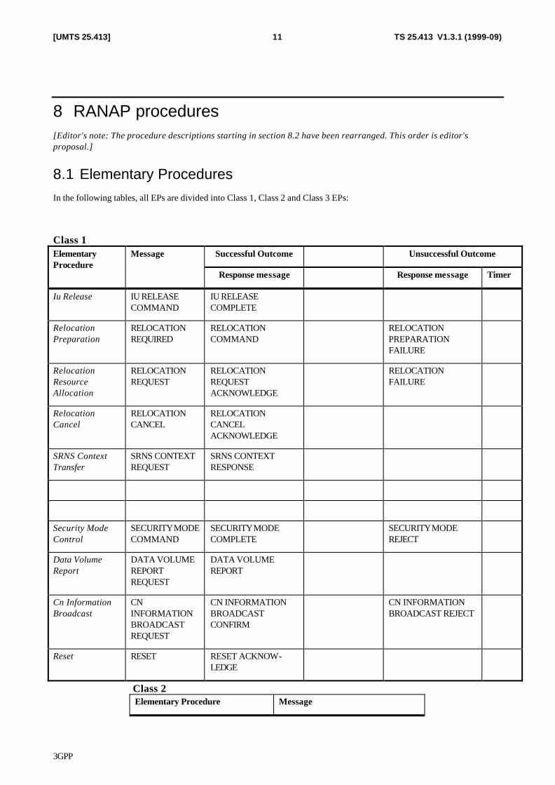
8.1 Elementary Procedures In the following tables, all EPs are divided into Class 1, Class 2 and Class 3 EPs:
Class 1 Successful Outcome Unsuccessful Outcome Elementary
Procedure Message
Response message Response message Timer
Iu Release IU RELEASE COMMAND
IU RELEASE COMPLETE
Relocation Preparation
RELOCATION REQUIRED
RELOCATION COMMAND
RELOCATION PREPARATION FAILURE
Relocation Resource Allocation
RELOCATION REQUEST
RELOCATION REQUEST ACKNOWLEDGE
RELOCATION FAILURE
Relocation Cancel
RELOCATION CANCEL
RELOCATION CANCEL ACKNOWLEDGE
SRNS Context Transfer
SRNS CONTEXT REQUEST
SRNS CONTEXT RESPONSE
Security Mode Control
SECURITY MODE COMMAND
SECURITY MODE COMPLETE
SECURITY MODE REJECT
Data Volume Report
DATA VOLUME REPORT REQUEST
DATA VOLUME REPORT
Cn Information Broadcast
CN INFORMATION BROADCAST REQUEST
CN INFORMATION BROADCAST CONFIRM
CN INFORMATION BROADCAST REJECT
Reset RESET RESET ACKNOW-LEDGE
Class 2 Elementary Procedure Message
3GPP
TS 25.413 V1.3.1 (1999-09)12[UMTS 25.413]
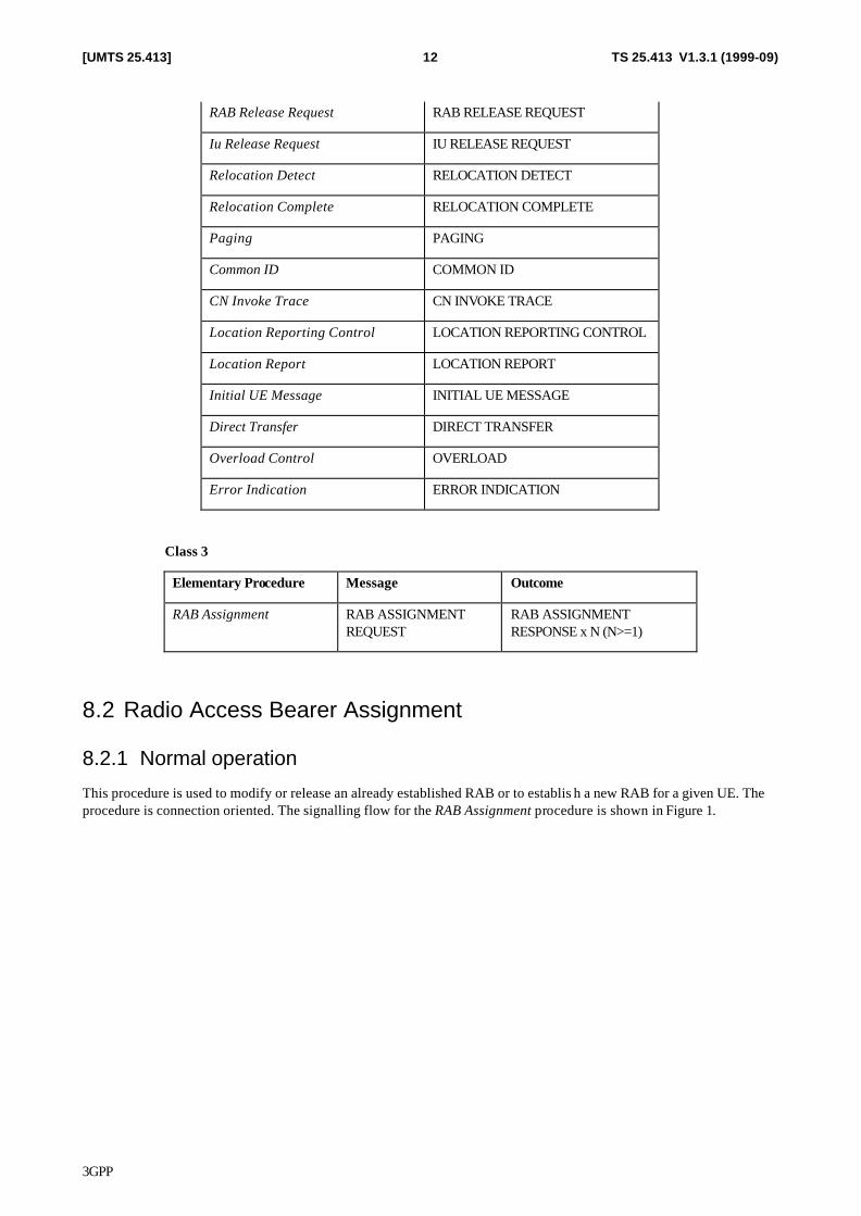
RAB Release Request RAB RELEASE REQUEST
Iu Release Request IU RELEASE REQUEST
Relocation Detect RELOCATION DETECT
Relocation Complete RELOCATION COMPLETE
Paging PAGING
Common ID COMMON ID
CN Invoke Trace CN INVOKE TRACE
Location Reporting Control LOCATION REPORTING CONTROL
Location Report LOCATION REPORT
Initial UE Message INITIAL UE MESSAGE
Direct Transfer DIRECT TRANSFER
Overload Control OVERLOAD
Error Indication ERROR INDICATION
Class 3
Elementary Procedure Message Outcome
RAB Assignment RAB ASSIGNMENT REQUEST
RAB ASSIGNMENT RESPONSE x N (N>=1)
8.2 Radio Access Bearer Assignment
8.2.1 Normal operation
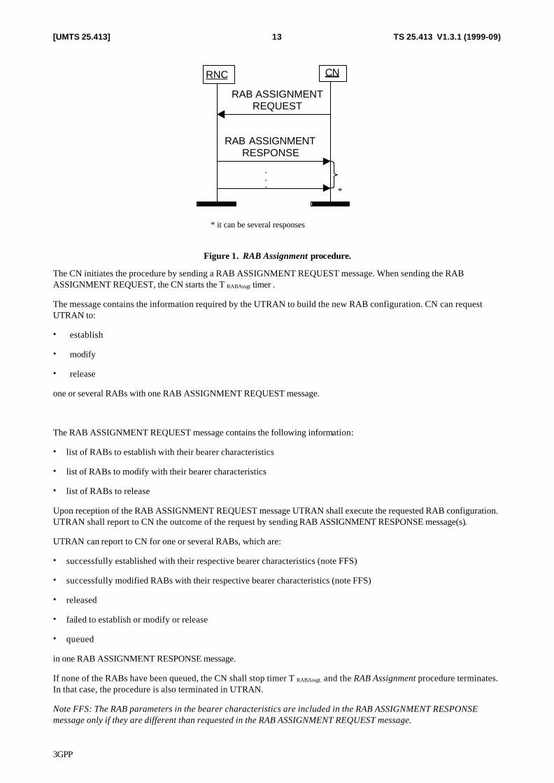
This procedure is used to modify or release an already established RAB or to establis h a new RAB for a given UE. The procedure is connection oriented. The signalling flow for the RAB Assignment procedure is shown in Figure 1.
3GPP
TS 25.413 V1.3.1 (1999-09)13[UMTS 25.413]
CN
RAB ASSIGNMENTREQUEST
RAB ASSIGNMENTRESPONSE
RNC
.
.
.*
* it can be several responses
Figure 1. RAB Assignment procedure.
The CN initiates the procedure by sending a RAB ASSIGNMENT REQUEST message. When sending the RAB ASSIGNMENT REQUEST, the CN starts the T RABAssgt timer .
The message contains the information required by the UTRAN to build the new RAB configuration. CN can request UTRAN to:
• establish
• modify
• release
one or several RABs with one RAB ASSIGNMENT REQUEST message.
The RAB ASSIGNMENT REQUEST message contains the following information:
• list of RABs to establish with their bearer characteristics
• list of RABs to modify with their bearer characteristics
• list of RABs to release
Upon reception of the RAB ASSIGNMENT REQUEST message UTRAN shall execute the requested RAB configuration. UTRAN shall report to CN the outcome of the request by sending RAB ASSIGNMENT RESPONSE message(s).
UTRAN can report to CN for one or several RABs, which are:
• successfully established with their respective bearer characteristics (note FFS)
• successfully modified RABs with their respective bearer characteristics (note FFS)
• released
• failed to establish or modify or release
• queued
in one RAB ASSIGNMENT RESPONSE message.
If none of the RABs have been queued, the CN shall stop timer T RABAssgt. and the RAB Assignment procedure terminates. In that case, the procedure is also terminated in UTRAN.
Note FFS: The RAB parameters in the bearer characteristics are included in the RAB ASSIGNMENT RESPONSE message only if they are different than requested in the RAB ASSIGNMENT REQUEST message.
3GPP
TS 25.413 V1.3.1 (1999-09)14[UMTS 25.413]
UTRAN shall report the outcome of a specific RAB configuration change only after the transport network control plane signalling, which is needed for this configuration establishment or modification, has been executed.
When the request to establish or modify one or several RABs is queued, UTRAN shall start the timer TQUEUING. This timer specifies the maximum time for queuing of the request of establishment or modification. The same timer TQUEUING is supervising all RABs being queued.
For each RABs that are queued the following outcomes are possible:
• successfully established or modified
• failed to establish or modify
• failed due to expiry of the timer TQUEUING
In the first RAB ASSIGNMENT RESPONSE message the RNC shall report about all RABs referenced in the RAB ASSIGNMENT REQUEST. Except in the case of TQUEUING expiry, UTRAN shall report the outcome of the queuing for every RAB individually or for several RABs in the RAB ASSIGNMENT RESPONSE message(s). This is left to implementation. UTRAN shall stop TQUEUING when all RABs have been either succesfully established or modified or failed to establish or modify. The RAB Assignment procedure is then terminated both in CN and UTRAN.
When CN receives the response that one or several RABs are queued, CN expects UTRAN to provide the outcome of the queuing function for each RAB before expiry of the T RABAssgt timer. Otherwise, CN considers the RAB Assignment procedure terminated.
In the case the timer TQUEUING expires, the RAB Assignment procedure terminates in UTRAN for all queued RABs, and UTRAN shall respond for all of them in one RAB ASSIGNMENT RESPONSE message. The RAB Assignment procedure is also terminated in CN.
8.2.2 Abnormal conditions
If the relocation becomes absolutely necessary during the RAB Assignment in order to keep the communication with the UE, the RNC may initiate the Relocation procedure while the RAB Assignment is in progress as follows:
1. The RNC shall terminate the RAB Assignment procedure:
• for all queued RABs,
• for RABs not already established or modified and
• for RABs not already released
with the cause ‘Relocation triggered’.
2. The RNC shall terminate the RAB Assignment procedure
• for RABs already established or modified but not yet reported to the CN and
• for RABs already released but not yet reported to the CN.
3. The RNC shall report this outcome of the procedure in one RAB ASSIGNMENT RESPONSE message.
4. The RNC shall invoke relocation by sending the RELOCATION REQUIRED to the active CN node(s).
5. The CN shall terminate the RAB Assignment procedure at reception of the RAB ASSIGNMENT RESPONSE message.
3GPP
TS 25.413 V1.3.1 (1999-09)15[UMTS 25.413]
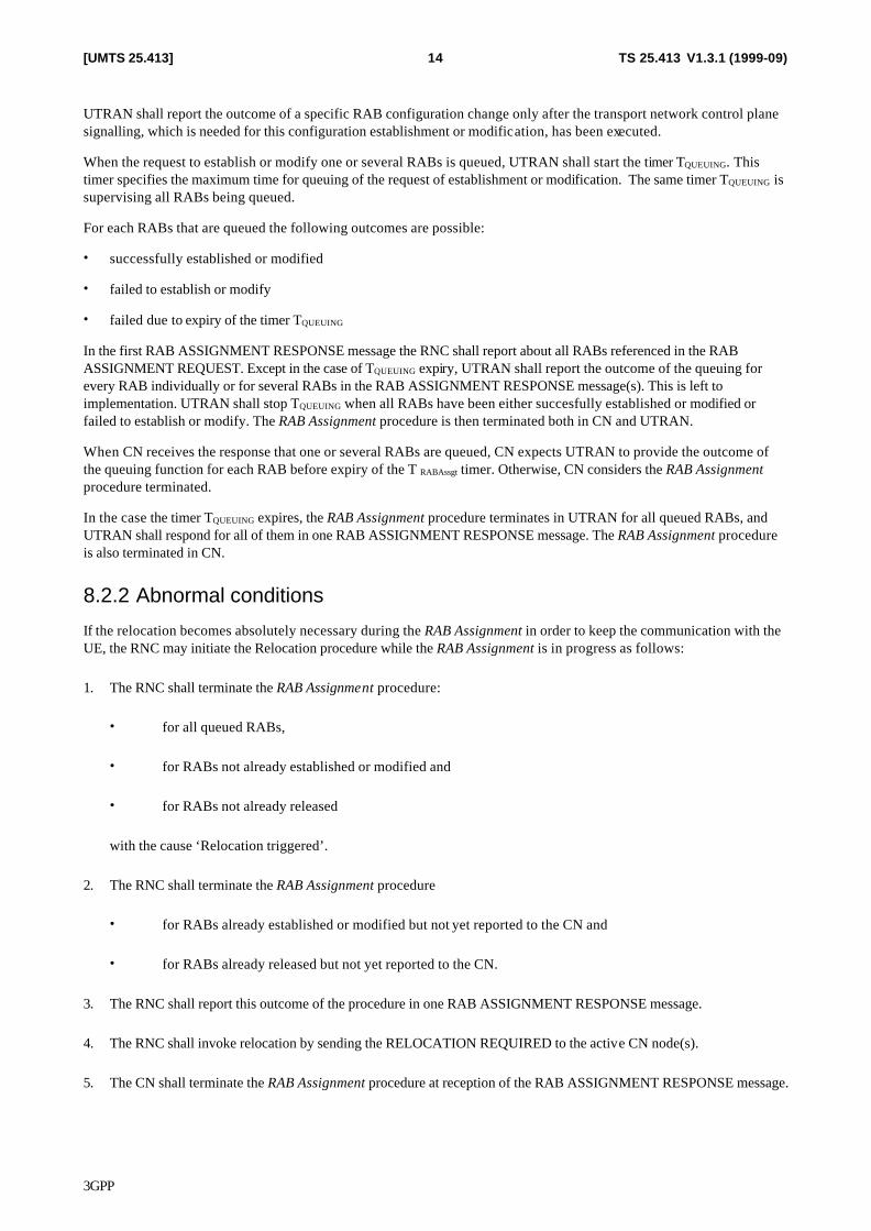
8.3 RAB Release Request This procedure is used to request a release of one or several radio access bearers from UTRAN side. Procedure is initiated by RNC generating a RAB RELEASE REQUEST message towards the CN. The procedure is connection oriented.
This message indicates the list of RABs requested to be released and cause value for each release request.
CN
RABRELEASE REQUEST
RNC
Figure 2. RAB Release Request procedure.
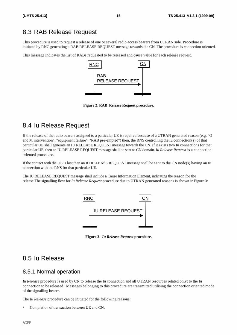
8.4 Iu Release Request If the release of the radio bearers assigned to a particular UE is required because of a UTRAN generated reason (e.g. "O and M intervention", "equipment failure", "RAB pre-empted") then, the RNS controlling the Iu connection(s) of that particular UE shall generate an IU RELEASE REQUEST message towards the CN. If it exists two Iu connections for that particular UE, then an IU RELEASE REQUEST message shall be sent to CN domain. Iu Release Request is a connection oriented procedure.
If the contact with the UE is lost then an IU RELEASE REQUEST message shall be sent to the CN node(s) having an Iu connection with the RNS for that particular UE.
The IU RELEASE REQUEST message shall include a Cause Information Element, indicating the reason for the release.The signalling flow for Iu Release Request procedure due to UTRAN generated reasons is shown in Figure 3:
CNRNC
IU RELEASE REQUEST
Figure 3. Iu Release Request procedure.
8.5 Iu Release
8.5.1 Normal operation
Iu Release procedure is used by CN to release the Iu connection and all UTRAN resources related onlyt to the Iu connection to be released. Messages belonging to this procedure are transmitted utilising the connection oriented mode of the signalling bearer.
The Iu Release procedure can be initiated for the following reasons:
• Completion of transaction between UE and CN.
3GPP
TS 25.413 V1.3.1 (1999-09)16[UMTS 25.413]
• UTRAN generated reasons, i.e. reception of IU RELEASE REQUEST.
• Completion of successful relocation of SRNS.
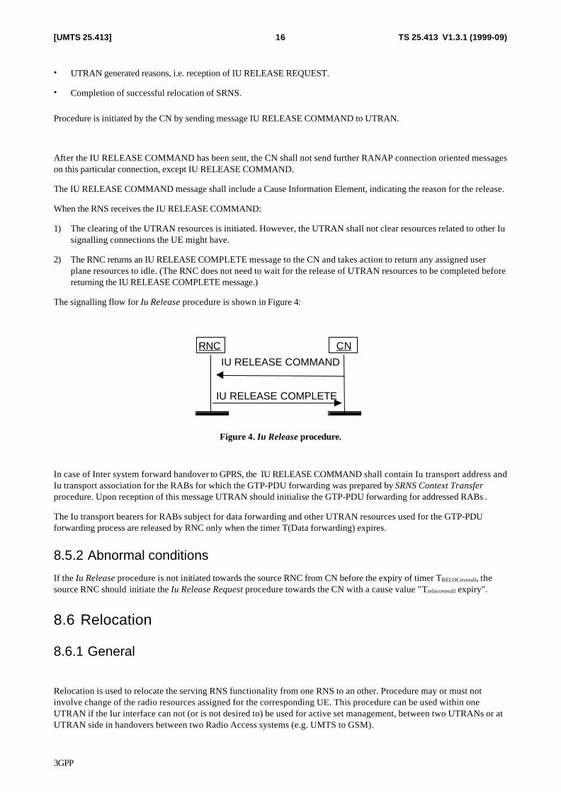
Procedure is initiated by the CN by sending message IU RELEASE COMMAND to UTRAN.
After the IU RELEASE COMMAND has been sent, the CN shall not send further RANAP connection oriented messages on this particular connection, except IU RELEASE COMMAND.
The IU RELEASE COMMAND message shall include a Cause Information Element, indicating the reason for the release.
When the RNS receives the IU RELEASE COMMAND:
1) The clearing of the UTRAN resources is initiated. However, the UTRAN shall not clear resources related to other Iu signalling connections the UE might have.
2) The RNC returns an IU RELEASE COMPLETE message to the CN and takes action to return any assigned user plane resources to idle. (The RNC does not need to wait for the release of UTRAN resources to be completed before returning the IU RELEASE COMPLETE message.)
The signalling flow for Iu Release procedure is shown in Figure 4:
CNRNC
IU RELEASE COMMAND
IU RELEASE COMPLETE
Figure 4. Iu Release procedure.
In case of Inter system forward handover to GPRS, the IU RELEASE COMMAND shall contain Iu transport address and Iu transport association for the RABs for which the GTP-PDU forwarding was prepared by SRNS Context Transfer procedure. Upon reception of this message UTRAN should initialise the GTP-PDU forwarding for addressed RABs .
The Iu transport bearers for RABs subject for data forwarding and other UTRAN resources used for the GTP-PDU forwarding process are released by RNC only when the timer T(Data forwarding) expires.
8.5.2 Abnormal conditions
If the Iu Release procedure is not initiated towards the source RNC from CN before the expiry of timer TRELOCoverall, the source RNC should initiate the Iu Release Request procedure towards the CN with a cause value "Trelocoverall expiry".
8.6 Relocation
8.6.1 General
Relocation is used to relocate the serving RNS functionality from one RNS to an other. Procedure may or must not involve change of the radio resources assigned for the corresponding UE. This procedure can be used within one UTRAN if the Iur interface can not (or is not desired to) be used for active set management, between two UTRANs or at UTRAN side in handovers between two Radio Access systems (e.g. UMTS to GSM).
3GPP
TS 25.413 V1.3.1 (1999-09)17[UMTS 25.413]
Relocation is carried over Iu interface, by the RANAP protocol.
All RANAP messages concerned with relocation are sent using the connection oriented mode of the signalling bearer.
8.6.2 Relocation Preparation
8.6.2.1 Successful operation
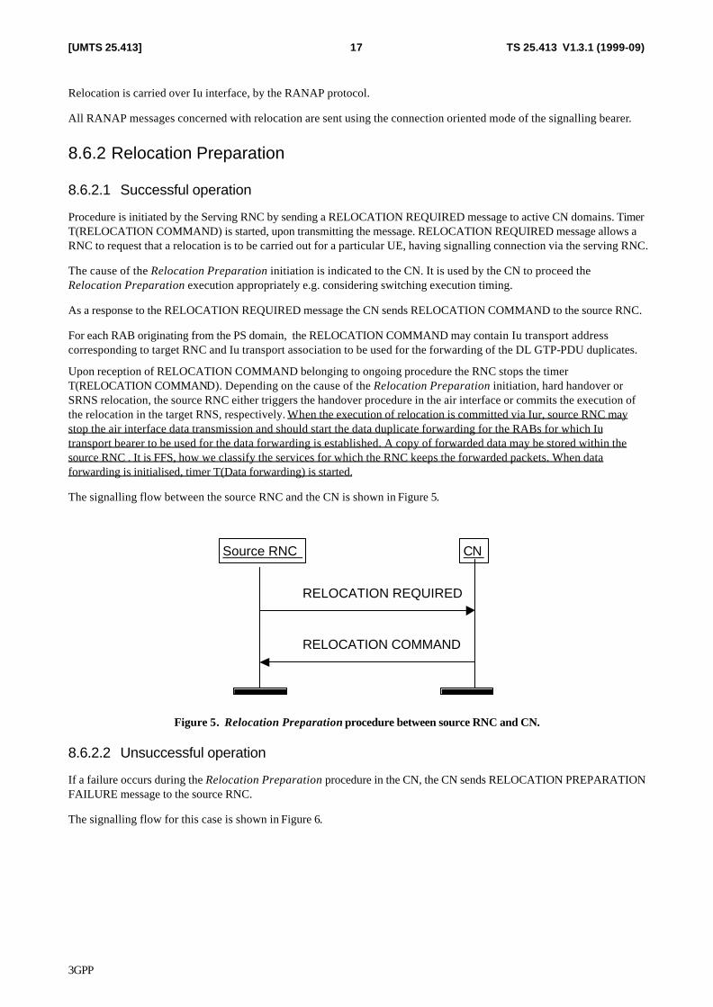
Procedure is initiated by the Serving RNC by sending a RELOCATION REQUIRED message to active CN domains. Timer T(RELOCATION COMMAND) is started, upon transmitting the message. RELOCATION REQUIRED message allows a RNC to request that a relocation is to be carried out for a particular UE, having signalling connection via the serving RNC.
The cause of the Relocation Preparation initiation is indicated to the CN. It is used by the CN to proceed the Relocation Preparation execution appropriately e.g. considering switching execution timing.
As a response to the RELOCATION REQUIRED message the CN sends RELOCATION COMMAND to the source RNC.
For each RAB originating from the PS domain, the RELOCATION COMMAND may contain Iu transport address corresponding to target RNC and Iu transport association to be used for the forwarding of the DL GTP-PDU duplicates.
Upon reception of RELOCATION COMMAND belonging to ongoing procedure the RNC stops the timer T(RELOCATION COMMAND). Depending on the cause of the Relocation Preparation initiation, hard handover or SRNS relocation, the source RNC either triggers the handover procedure in the air interface or commits the execution of the relocation in the target RNS, respectively. When the execution of relocation is committed via Iur, source RNC may stop the air interface data transmission and should start the data duplicate forwarding for the RABs for which Iu transport bearer to be used for the data forwarding is established. A copy of forwarded data may be stored within the source RNC . It is FFS, how we classify the services for which the RNC keeps the forwarded packets. When data forwarding is initialised, timer T(Data forwarding) is started.
The signalling flow between the source RNC and the CN is shown in Figure 5.
CNSource RNC
RELOCATION COMMAND
RELOCATION REQUIRED
Figure 5. Relocation Preparation procedure between source RNC and CN.
8.6.2.2 Unsuccessful operation
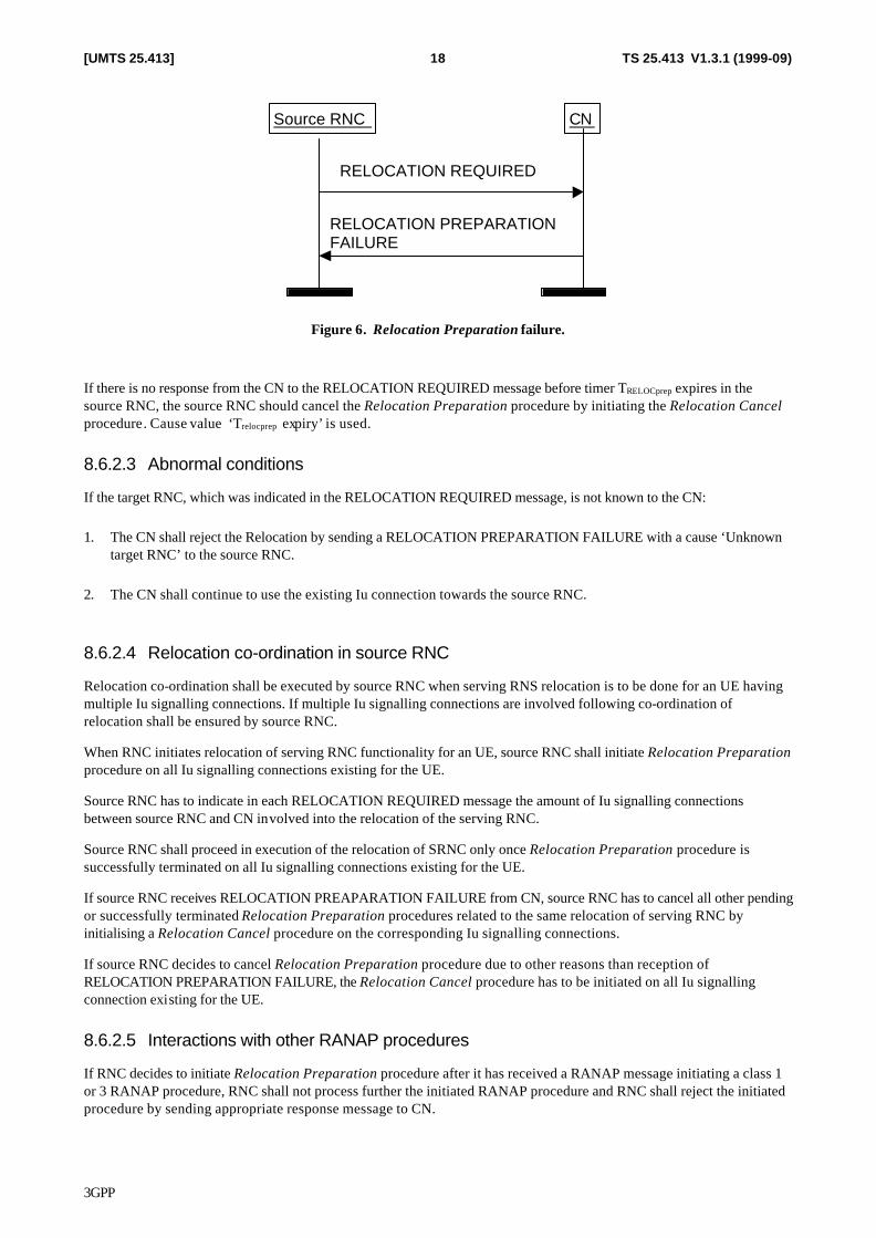
If a failure occurs during the Relocation Preparation procedure in the CN, the CN sends RELOCATION PREPARATION FAILURE message to the source RNC.
The signalling flow for this case is shown in Figure 6.
3GPP
TS 25.413 V1.3.1 (1999-09)18[UMTS 25.413]
CNSource RNC
RELOCATION PREPARATIONFAILURE
RELOCATION REQUIRED
Figure 6. Relocation Preparation failure.
If there is no response from the CN to the RELOCATION REQUIRED message before timer TRELOCprep expires in the source RNC, the source RNC should cancel the Relocation Preparation procedure by initiating the Relocation Cancel procedure. Cause value ‘Trelocprep expiry’ is used.
8.6.2.3 Abnormal conditions
If the target RNC, which was indicated in the RELOCATION REQUIRED message, is not known to the CN:
1. The CN shall reject the Relocation by sending a RELOCATION PREPARATION FAILURE with a cause ‘Unknown target RNC’ to the source RNC.
2. The CN shall continue to use the existing Iu connection towards the source RNC.
8.6.2.4 Relocation co-ordination in source RNC
Relocation co-ordination shall be executed by source RNC when serving RNS relocation is to be done for an UE having multiple Iu signalling connections. If multiple Iu signalling connections are involved following co-ordination of relocation shall be ensured by source RNC.
When RNC initiates relocation of serving RNC functionality for an UE, source RNC shall initiate Relocation Preparation procedure on all Iu signalling connections existing for the UE.
Source RNC has to indicate in each RELOCATION REQUIRED message the amount of Iu signalling connections between source RNC and CN involved into the relocation of the serving RNC.
Source RNC shall proceed in execution of the relocation of SRNC only once Relocation Preparation procedure is successfully terminated on all Iu signalling connections existing for the UE.
If source RNC receives RELOCATION PREAPARATION FAILURE from CN, source RNC has to cancel all other pending or successfully terminated Relocation Preparation procedures related to the same relocation of serving RNC by initialising a Relocation Cancel procedure on the corresponding Iu signalling connections.
If source RNC decides to cancel Relocation Preparation procedure due to other reasons than reception of RELOCATION PREPARATION FAILURE, the Relocation Cancel procedure has to be initiated on all Iu signalling connection existing for the UE.
8.6.2.5 Interactions with other RANAP procedures
If RNC decides to initiate Relocation Preparation procedure after it has received a RANAP message initiating a class 1 or 3 RANAP procedure, RNC shall not process further the initiated RANAP procedure and RNC shall reject the initiated procedure by sending appropriate response message to CN.
3GPP
TS 25.413 V1.3.1 (1999-09)19[UMTS 25.413]
If, after RELOCATION REQUIRED is sent, RNC receives a RANAP message initiating a RANAP class 1 or 3 procedure, RNC shall either
• cancel the relocation of SRNS (Execute Relocation Cancel procedure) and then continue the processing of the initiated RANAP procedure.
or
• reject the initiated RANAP procedure by sending appropriate response message to CN.
or
• execute the RANAP procedures.
If, after RELOCATION REQUIRED is sent RNC receives a RANAP message initiating a RANAP class 2 procedure (except Direct Transfer, which is handled normally) and the RNC does not decide to cancel the relocation, RNC shall ignore the received RANAP mesage.
When RELOCATION COMMAND is received from CN all RANAP messages (except those RANAP procedures that override other RANAP procedures) received via the same signalling bearer shall be ignored by RNC.
8.6.3 Relocation resource allocation
8.6.3.1 Successful operation
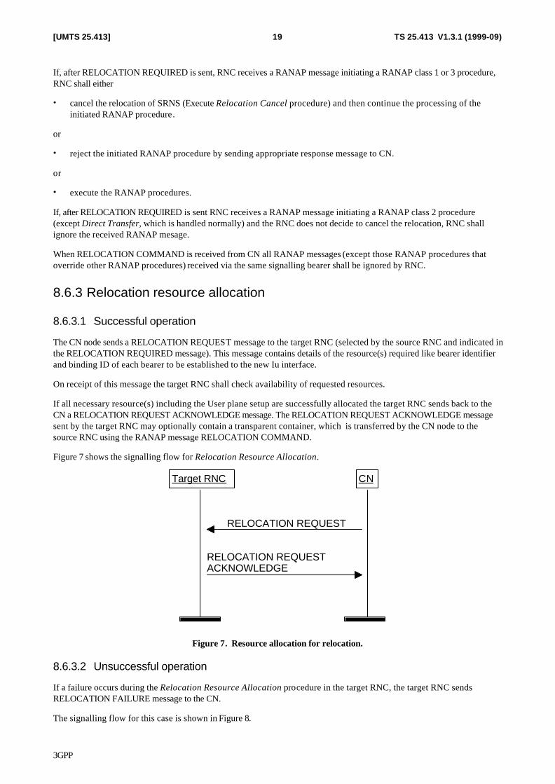
The CN node sends a RELOCATION REQUEST message to the target RNC (selected by the source RNC and indicated in the RELOCATION REQUIRED message). This message contains details of the resource(s) required like bearer identifier and binding ID of each bearer to be established to the new Iu interface.
On receipt of this message the target RNC shall check availability of requested resources.
If all necessary resource(s) including the User plane setup are successfully allocated the target RNC sends back to the CN a RELOCATION REQUEST ACKNOWLEDGE message. The RELOCATION REQUEST ACKNOWLEDGE message sent by the target RNC may optionally contain a transparent container, which is transferred by the CN node to the source RNC using the RANAP message RELOCATION COMMAND.
Figure 7 shows the signalling flow for Relocation Resource Allocation.
CNTarget RNC
RELOCATION REQUESTACKNOWLEDGE
RELOCATION REQUEST
Figure 7. Resource allocation for relocation.
8.6.3.2 Unsuccessful operation
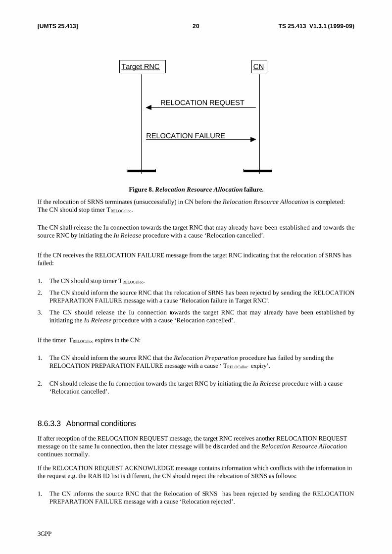
If a failure occurs during the Relocation Resource Allocation procedure in the target RNC, the target RNC sends RELOCATION FAILURE message to the CN.
The signalling flow for this case is shown in Figure 8.
3GPP
TS 25.413 V1.3.1 (1999-09)20[UMTS 25.413]
CNTarget RNC
RELOCATION FAILURE
RELOCATION REQUEST
Figure 8. Relocation Resource Allocation failure.
If the relocation of SRNS terminates (unsuccessfully) in CN before the Relocation Resource Allocation is completed: The CN should stop timer TRELOCalloc.
The CN shall release the Iu connection towards the target RNC that may already have been established and towards the source RNC by initiating the Iu Release procedure with a cause ‘Relocation cancelled’.
If the CN receives the RELOCATION FAILURE message from the target RNC indicating that the relocation of SRNS has failed:
1. The CN should stop timer TRELOCalloc.
2. The CN should inform the source RNC that the relocation of SRNS has been rejected by sending the RELOCATION PREPARATION FAILURE message with a cause ‘Relocation failure in Target RNC’.
3. The CN should release the Iu connection towards the target RNC that may already have been established by initiating the Iu Release procedure with a cause ‘Relocation cancelled’.
If the timer TRELOCalloc expires in the CN:
1. The CN should inform the source RNC that the Relocation Preparation procedure has failed by sending the RELOCATION PREPARATION FAILURE message with a cause ‘ TRELOCalloc expiry’.
2. CN should release the Iu connection towards the target RNC by initiating the Iu Release procedure with a cause ‘Relocation cancelled’.
8.6.3.3 Abnormal conditions
If after reception of the RELOCATION REQUEST message, the target RNC receives another RELOCATION REQUEST message on the same Iu connection, then the later message will be discarded and the Relocation Resource Allocation continues normally.
If the RELOCATION REQUEST ACKNOWLEDGE message contains information which conflicts with the information in the request e.g. the RAB ID list is different, the CN should reject the relocation of SRNS as follows:
1. The CN informs the source RNC that the Relocation of SRNS has been rejected by sending the RELOCATION PREPARATION FAILURE message with a cause ‘Relocation rejected’.
3GPP
TS 25.413 V1.3.1 (1999-09)21[UMTS 25.413]
2. The CN shall release the Iu connection towards the target RNC that may already have been established by initiating the Iu Release procedure with a cause ‘Relocation cancelled’.
3. The CN shall continue to use the existing Iu interface towards the source RNC.
4. The CN shall stop timer TRELOCalloc
8.6.3.4 Relocation co-ordination in target RNC
Relocation co-ordination shall be executed by target RNC when a received RELOCATION REQUEST message indicates that more than one Iu signalling connection is involved.
Target RNC should handle Relocation Resource Allocation procedures in general independently of each other. However the information which may depend on the contents of all the expected RELOCATION REQUEST messages and which is to be sent in the transparent field to the source RNC (e.g. information of new radio resources) shall be sent only after all expected RELOCATION REQUEST messages are received and analysed.
Target RNC has to ensure that there is no conflicting information in target RNC to source RNC Transparent fields in RELOCATION REQUEST ACKNOWLEDGE messages transmitted via different Iu signalling connections and related to the same relocation.
The selection of signalling connection utilised for the different kind of transparent information in RELOCATION REQUEST ACKNOWLEDGE message is not dependent on the signalling connection via which transparent information was received in RELOCATION REQUEST message.
8.6.4 Relocation Detect
8.6.4.1 Normal operation
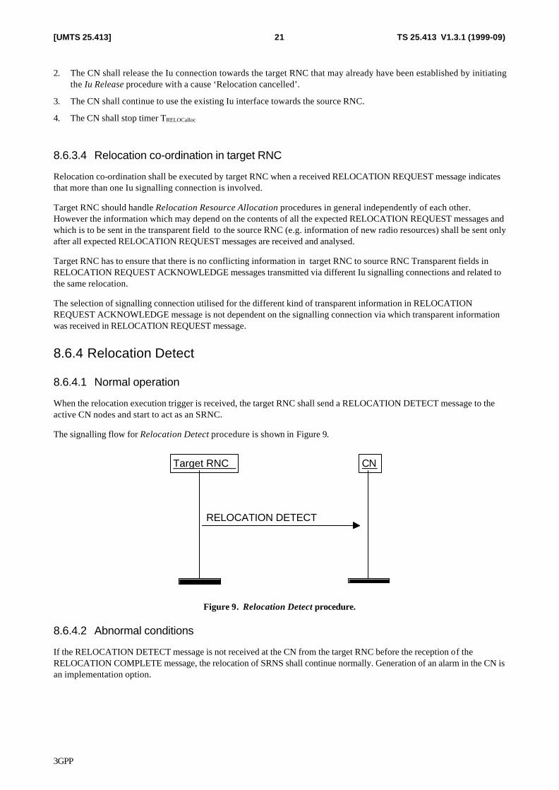
When the relocation execution trigger is received, the target RNC shall send a RELOCATION DETECT message to the active CN nodes and start to act as an SRNC.
The signalling flow for Relocation Detect procedure is shown in Figure 9.
CNTarget RNC
RELOCATION DETECT
Figure 9. Relocation Detect procedure.
8.6.4.2 Abnormal conditions
If the RELOCATION DETECT message is not received at the CN from the target RNC before the reception of the RELOCATION COMPLETE message, the relocation of SRNS shall continue normally. Generation of an alarm in the CN is an implementation option.
3GPP
TS 25.413 V1.3.1 (1999-09)22[UMTS 25.413]
8.6.5 Relocation Complete
8.6.5.1 Normal operation
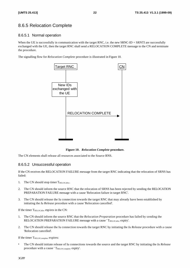
When the UE is successfully in communication with the target RNC, i.e. the new SRNC-ID + SRNTI are successfully exchanged with the UE, then the target RNC shall send a RELOCATION COMPLETE message to the CN and terminate the procedure.
The signalling flow for Relocation Complete procedure is illustrated in Figure 10.
CNTarget RNC
New IDsexchanged with
the UE
RELOCATION COMPLETE
Figure 10. Relocation Complete procedure.
The CN elements shall release all resources associated to the Source RNS.
8.6.5.2 Unsuccessful operation
If the CN receives the RELOCATION FAILURE message from the target RNC indicating that the relocation of SRNS has failed:
1. The CN should stop timer TRELOCalloc.
2. The CN should inform the source RNC that the relocation of SRNS has been rejected by sending the RELOCATION PREPARATION FAILURE message with a cause 'Relocation failure in target RNC'.
3. The CN should release the Iu connection towards the target RNC that may already have been established by initiating the Iu Release procedure with a cause 'Relocation cancelled'.
If the timer TRELOCalloc expires in the CN:
1. The CN should inform the source RNC that the Relocation Preparation procedure has failed by sending the RELOCATION PREPARATION FAILURE message with a cause ' TRELOCalloc expiry'.
2. The CN should release the Iu connection towards the target RNC by initiating the Iu Release procedure with a cause 'Relocation cancelled'.
If the timer TRELOCcomplete expires:
• The CN should initiate release of Iu connections towards the source and the target RNC by initiating the Iu Release procedure with a cause ' TRELOCcomplete expiry'.
3GPP
TS 25.413 V1.3.1 (1999-09)23[UMTS 25.413]
If the relocation of SRNS terminates (unsuccessfully) in the CN before the Relocation Resource Allocation is completed:
1. The CN should stop the timer TRELOCcomplete .
2. The CN should initiate release of Iu connection towards the target RNC by initiating the Iu Release procedure with a cause 'Relocation cancelled before completion'.
8.6.6 Relocation Cancel
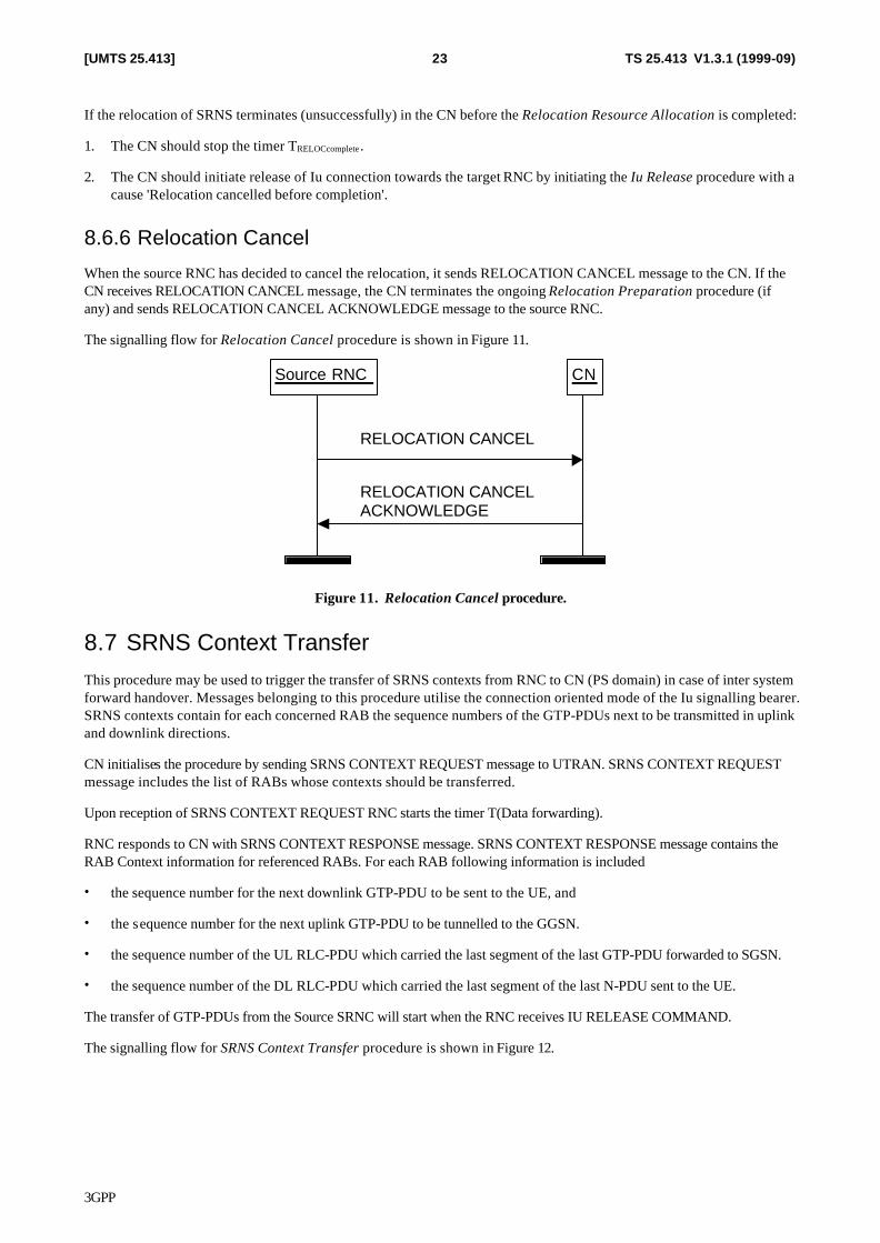
When the source RNC has decided to cancel the relocation, it sends RELOCATION CANCEL message to the CN. If the CN receives RELOCATION CANCEL message, the CN terminates the ongoing Relocation Preparation procedure (if any) and sends RELOCATION CANCEL ACKNOWLEDGE message to the source RNC.
The signalling flow for Relocation Cancel procedure is shown in Figure 11.
CNSource RNC
RELOCATION CANCELACKNOWLEDGE
RELOCATION CANCEL
Figure 11. Relocation Cancel procedure.
8.7 SRNS Context Transfer This procedure may be used to trigger the transfer of SRNS contexts from RNC to CN (PS domain) in case of inter system forward handover. Messages belonging to this procedure utilise the connection oriented mode of the Iu signalling bearer. SRNS contexts contain for each concerned RAB the sequence numbers of the GTP-PDUs next to be transmitted in uplink and downlink directions.
CN initialises the procedure by sending SRNS CONTEXT REQUEST message to UTRAN. SRNS CONTEXT REQUEST message includes the list of RABs whose contexts should be transferred.
Upon reception of SRNS CONTEXT REQUEST RNC starts the timer T(Data forwarding).
RNC responds to CN with SRNS CONTEXT RESPONSE message. SRNS CONTEXT RESPONSE message contains the RAB Context information for referenced RABs. For each RAB following information is included
• the sequence number for the next downlink GTP-PDU to be sent to the UE, and
• the sequence number for the next uplink GTP-PDU to be tunnelled to the GGSN.
• the sequence number of the UL RLC-PDU which carried the last segment of the last GTP-PDU forwarded to SGSN.
• the sequence number of the DL RLC-PDU which carried the last segment of the last N-PDU sent to the UE.
The transfer of GTP-PDUs from the Source SRNC will start when the RNC receives IU RELEASE COMMAND.
The signalling flow for SRNS Context Transfer procedure is shown in Figure 12.
3GPP
TS 25.413 V1.3.1 (1999-09)24[UMTS 25.413]
CNRNC
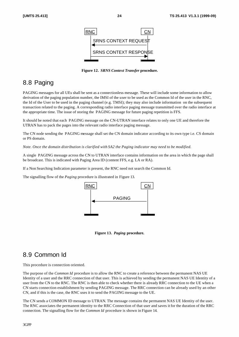
SRNS CONTEXT REQUEST
SRNS CONTEXT RESPONSE
Figure 12. SRNS Context Transfer procedure.
8.8 Paging PAGING messages for all UEs shall be sent as a connectionless message. These will include some information to allow derivation of the paging population number, the IMSI of the user to be used as the Common Id of the user in the RNC, the Id of the User to be used in the paging channel (e.g. TMSI); they may also include information on the subsequent transaction related to the paging. A corresponding radio interface paging message transmitted over the radio interface at the appropriate time. The issue of storing the PAGING message for future paging repetition is FFS.
It should be noted that each PAGING message on the CN-UTRAN interface relates to only one UE and therefore the UTRAN has to pack the pages into the relevant radio interface paging message.
The CN node sending the PAGING message shall set the CN domain indicator according to its own type i.e. CS domain or PS domain.
Note. Once the domain distribution is clarified with SA2 the Paging indicator may need to be modified.
A single PAGING message across the CN to UTRAN interface contains information on the area in which the page shall be broadcast. This is indicated with Paging Area ID (content FFS, e.g. LA or RA).
If a Non Searching Indication parameter is present, the RNC need not search the Common Id.
The signalling flow of the Paging procedure is illustrated in Figure 13.
CNRNC
PAGING
Figure 13. Paging procedure.
8.9 Common Id This procedure is connection oriented.
The purpose of the Common Id procedure is to allow the RNC to create a reference between the permanent NAS UE Identity of a user and the RRC connection of that user. This is achieved by sending the permanent NAS UE Identity of a user from the CN to the RNC. The RNC is then able to check whether there is already RRC connection to the UE when a CN starts connection establishment by sending PAGING message. The RRC connection can be already used by an other CN, and if this is the case, the RNC uses it to send the PAGING message to the UE.
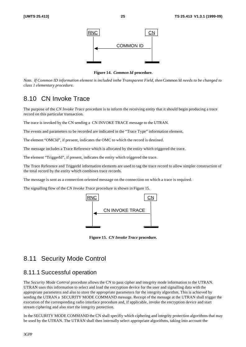
The CN sends a COMMON ID message to UTRAN. The message contains the permanent NAS UE Identity of the user. The RNC associates the permanent identity to the RRC Connection of that user and saves it for the duration of the RRC connection. The signalling flow for the Common Id procedure is shown in Figure 14.
3GPP
TS 25.413 V1.3.1 (1999-09)25[UMTS 25.413]
CNRNC
COMMON ID
Figure 14. Common Id procedure.
Note. If Common ID information element is included inthe Transparent Field, then Common Id needs to be changed to class 1 elementary procedure.
8.10 CN Invoke Trace The purpose of the CN Invoke Trace procedure is to inform the receiving entity that it should begin producing a trace record on this particular transaction.
The trace is invoked by the CN sending a CN INVOKE TRACE message to the UTRAN.
The events and parameters to be recorded are indicated in the “Trace Type” information element.
The element “OMCId”, if present, indicates the OMC to which the record is destined.
The message includes a Trace Reference which is allocated by the entity which triggered the trace.
The element “TriggerId”, if present, indicates the entity which triggered the trace.
The Trace Reference and TriggerId information elements are used to tag the trace record to allow simpler construction of the total record by the entity which combines trace records.
The message is sent as a connection oriented message on the connection on which a trace is required.
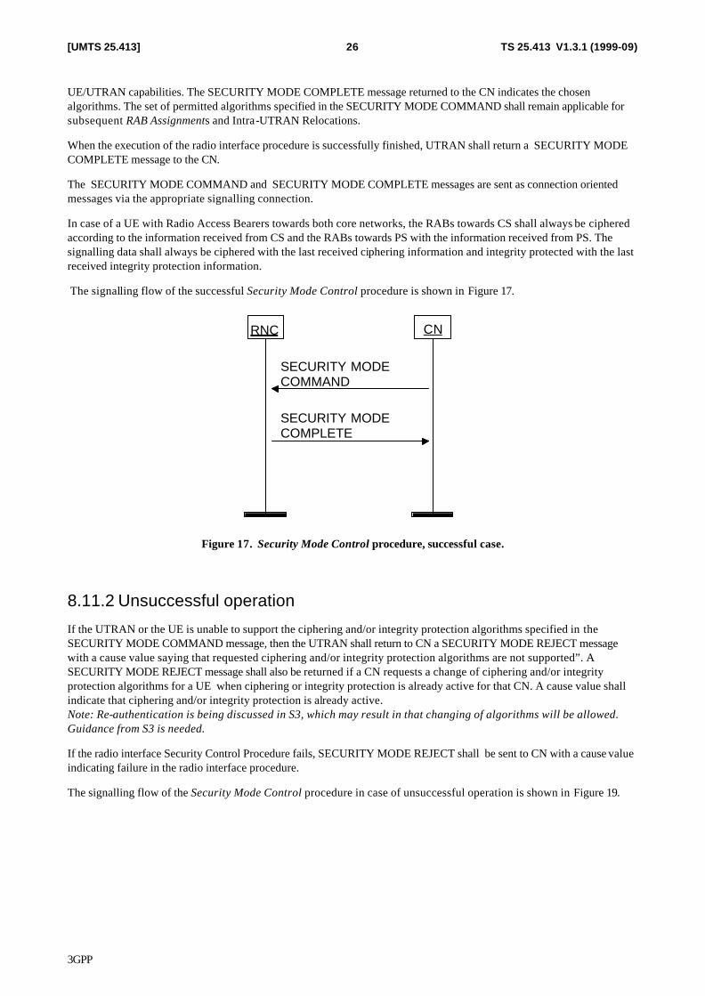
The signalling flow of the CN Invoke Trace procedure is shown in Figure 15.
CNRNC
CN INVOKE TRACE
Figure 15. CN Invoke Trace procedure.
8.11 Security Mode Control
8.11.1 Successful operation
The Security Mode Control procedure allows the CN to pass cipher and integrity mode information to the UTRAN. UTRAN uses this information to select and load the encryption device for the user and signalling data with the appropriate parameters and also to store the appropriate parameters for the integrity algorithm. This is achieved by sending the UTRAN a SECURITY MODE COMMAND message. Receipt of the message at the UTRAN shall trigger the execution of the corresponding radio interface procedure and, if applicable, invoke the encryption device and start stream ciphering and also start the integrity protection.
In the SECURITY MODE COMMAND the CN shall specifiy which ciphering and integrity protection algorithms that may be used by the UTRAN. The UTRAN shall then internally select appropriate algorithms, taking into account the
3GPP
TS 25.413 V1.3.1 (1999-09)26[UMTS 25.413]
UE/UTRAN capabilities. The SECURITY MODE COMPLETE message returned to the CN indicates the chosen algorithms. The set of permitted algorithms specified in the SECURITY MODE COMMAND shall remain applicable for subsequent RAB Assignments and Intra-UTRAN Relocations.
When the execution of the radio interface procedure is successfully finished, UTRAN shall return a SECURITY MODE COMPLETE message to the CN.
The SECURITY MODE COMMAND and SECURITY MODE COMPLETE messages are sent as connection oriented messages via the appropriate signalling connection.
In case of a UE with Radio Access Bearers towards both core networks, the RABs towards CS shall always be ciphered according to the information received from CS and the RABs towards PS with the information received from PS. The signalling data shall always be ciphered with the last received ciphering information and integrity protected with the last received integrity protection information.
The signalling flow of the successful Security Mode Control procedure is shown in Figure 17.
CNRNC
SECURITY MODECOMMAND
SECURITY MODECOMPLETE
Figure 17. Security Mode Control procedure, successful case.
8.11.2 Unsuccessful operation
If the UTRAN or the UE is unable to support the ciphering and/or integrity protection algorithms specified in the SECURITY MODE COMMAND message, then the UTRAN shall return to CN a SECURITY MODE REJECT message with a cause value saying that requested ciphering and/or integrity protection algorithms are not supported”. A SECURITY MODE REJECT message shall also be returned if a CN requests a change of ciphering and/or integrity protection algorithms for a UE when ciphering or integrity protection is already active for that CN. A cause value shall indicate that ciphering and/or integrity protection is already active. Note: Re-authentication is being discussed in S3, which may result in that changing of algorithms will be allowed. Guidance from S3 is needed.
If the radio interface Security Control Procedure fails, SECURITY MODE REJECT shall be sent to CN with a cause value indicating failure in the radio interface procedure.
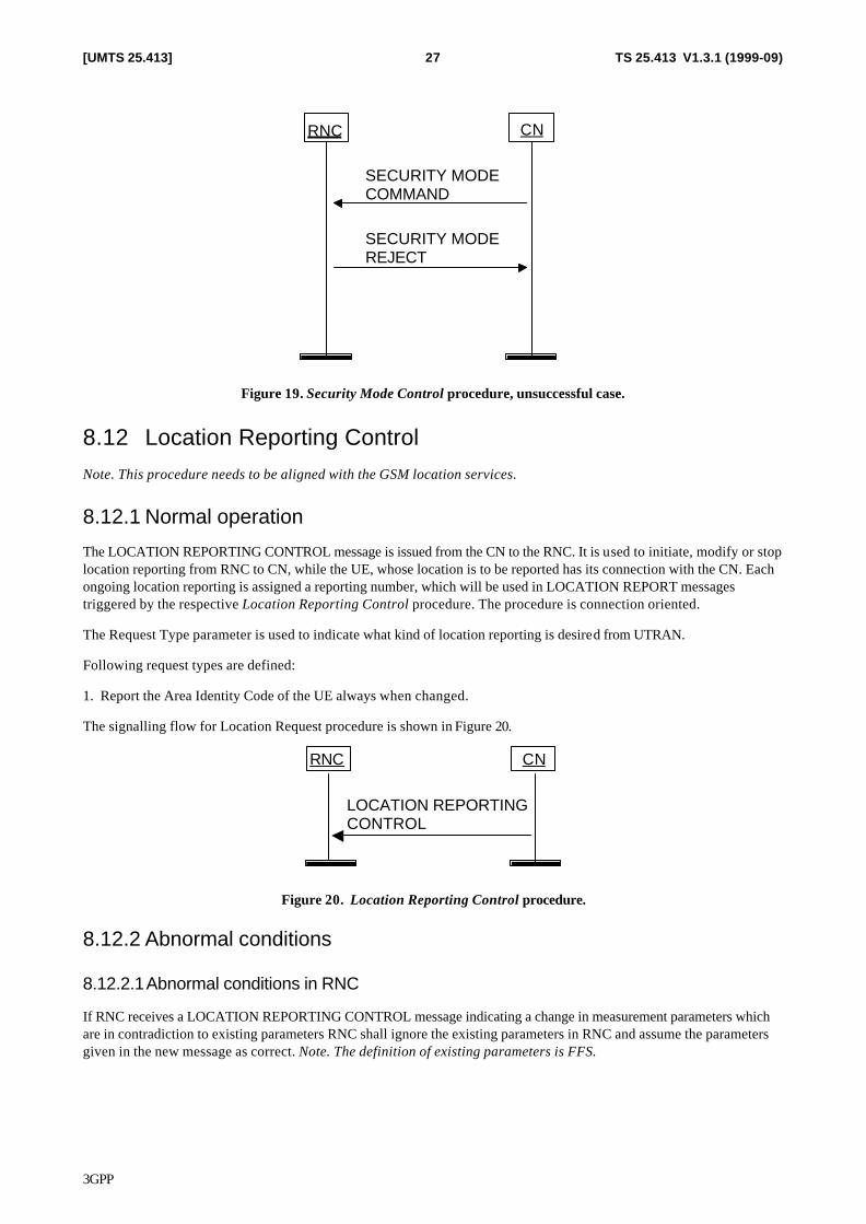
The signalling flow of the Security Mode Control procedure in case of unsuccessful operation is shown in Figure 19.
3GPP
TS 25.413 V1.3.1 (1999-09)27[UMTS 25.413]
CNRNC
SECURITY MODECOMMAND
SECURITY MODEREJECT
Figure 19. Security Mode Control procedure, unsuccessful case.
8.12 Location Reporting Control Note. This procedure needs to be aligned with the GSM location services.
8.12.1 Normal operation
The LOCATION REPORTING CONTROL message is issued from the CN to the RNC. It is used to initiate, modify or stop location reporting from RNC to CN, while the UE, whose location is to be reported has its connection with the CN. Each ongoing location reporting is assigned a reporting number, which will be used in LOCATION REPORT messages triggered by the respective Location Reporting Control procedure. The procedure is connection oriented.
The Request Type parameter is used to indicate what kind of location reporting is desired from UTRAN.
Following request types are defined:
1. Report the Area Identity Code of the UE always when changed.
The signalling flow for Location Request procedure is shown in Figure 20.
CNRNC
LOCATION REPORTINGCONTROL
Figure 20. Location Reporting Control procedure.
8.12.2 Abnormal conditions
8.12.2.1 Abnormal conditions in RNC
If RNC receives a LOCATION REPORTING CONTROL message indicating a change in measurement parameters which are in contradiction to existing parameters RNC shall ignore the existing parameters in RNC and assume the parameters given in the new message as correct. Note. The definition of existing parameters is FFS.
3GPP
TS 25.413 V1.3.1 (1999-09)28[UMTS 25.413]
8.13 Location Report
8.13.1 Successful operation
The LOCATION REPORT message is issued from the RNC to the CN. It is used to provide the UE location information to the CN. This may be used as a response for the LOCATION REPORTING CONTROL message. Also, when a user enters or leaves a classified area set by O&M, e.g. disaster area, a LOCATION REPORT message will be sent to the CN. Cause information is included in the message. Other triggers of this message are FFS. The procedure is connection oriented.
In case the reporting of Area Identity Code is requested by CN, then RNC shall issue a location report always when the information given in the previous LOCATION REPORT or INITIAL UE MESSAGE is not anymore valid. In this case RNC shall include to the LOCATION REPORT message the Area Identity Code which indicates one of the cells from which the UE is consuming radio resources.
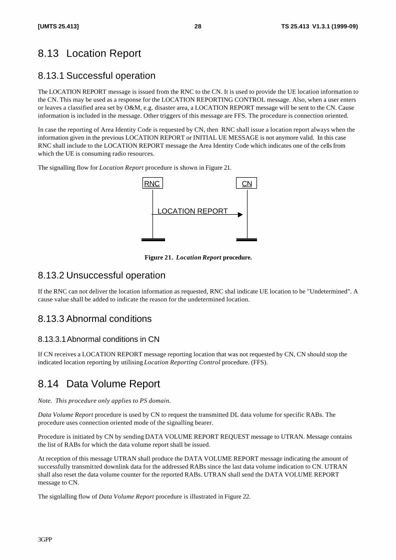
The signalling flow for Location Report procedure is shown in Figure 21.
CNRNC
LOCATION REPORT
Figure 21. Location Report procedure.
8.13.2 Unsuccessful operation
If the RNC can not deliver the location information as requested, RNC shal indicate UE location to be "Undetermined". A cause value shall be added to indicate the reason for the undetermined location.
8.13.3 Abnormal conditions
8.13.3.1 Abnormal conditions in CN
If CN receives a LOCATION REPORT message reporting location that was not requested by CN, CN should stop the indicated location reporting by utilising Location Reporting Control procedure. (FFS).
8.14 Data Volume Report Note. This procedure only applies to PS domain.
Data Volume Report procedure is used by CN to request the transmitted DL data volume for specific RABs. The procedure uses connection oriented mode of the signalling bearer.
Procedure is initiated by CN by sending DATA VOLUME REPORT REQUEST message to UTRAN. Message contains the list of RABs for which the data volume report shall be issued.
At reception of this message UTRAN shall produce the DATA VOLUME REPORT message indicating the amount of successfully transmitted downlink data for the addressed RABs since the last data volume indication to CN. UTRAN shall also reset the data volume counter for the reported RABs. UTRAN shall send the DATA VOLUME REPORT message to CN.
The signlalling flow of Data Volume Report procedure is illustrated in Figure 22.
3GPP
TS 25.413 V1.3.1 (1999-09)29[UMTS 25.413]
CNRNC
DATA VOLUME REPORT
DATA VOLUME REPORT REQUEST
Figure 22. Data Volume Report procedure.
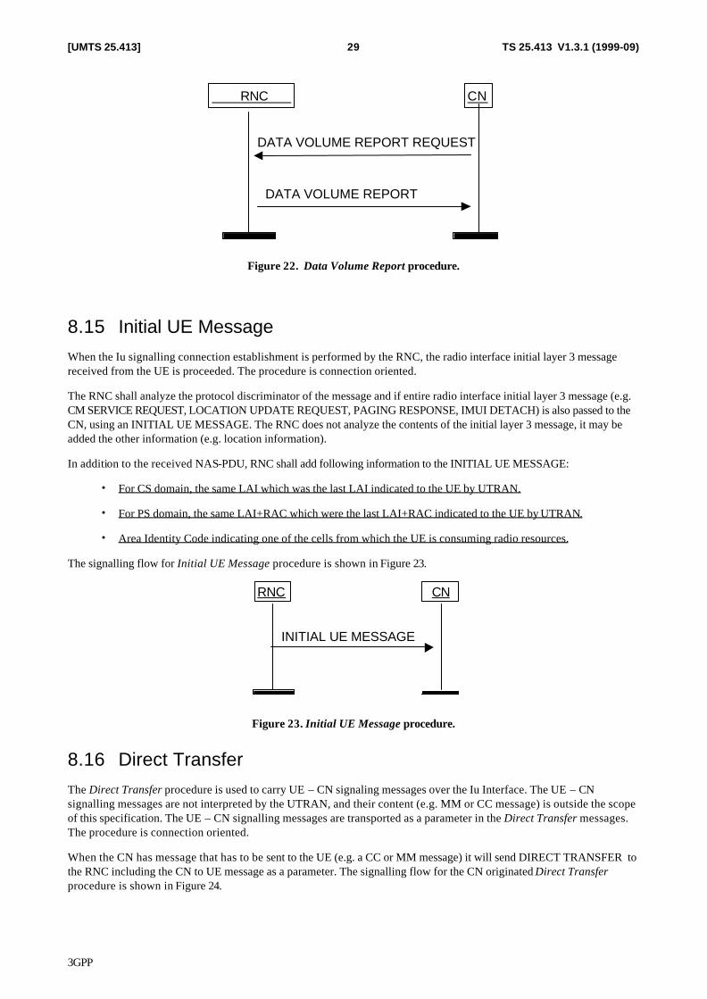
8.15 Initial UE Message When the Iu signalling connection establishment is performed by the RNC, the radio interface initial layer 3 message received from the UE is proceeded. The procedure is connection oriented.
The RNC shall analyze the protocol discriminator of the message and if entire radio interface initial layer 3 message (e.g. CM SERVICE REQUEST, LOCATION UPDATE REQUEST, PAGING RESPONSE, IMUI DETACH) is also passed to the CN, using an INITIAL UE MESSAGE. The RNC does not analyze the contents of the initial layer 3 message, it may be added the other information (e.g. location information).
In addition to the received NAS-PDU, RNC shall add following information to the INITIAL UE MESSAGE:
• For CS domain, the same LAI which was the last LAI indicated to the UE by UTRAN.
• For PS domain, the same LAI+RAC which were the last LAI+RAC indicated to the UE by UTRAN.
• Area Identity Code indicating one of the cells from which the UE is consuming radio resources.
The signalling flow for Initial UE Message procedure is shown in Figure 23.
CNRNC
INITIAL UE MESSAGE
Figure 23. Initial UE Message procedure.
8.16 Direct Transfer The Direct Transfer procedure is used to carry UE – CN signaling messages over the Iu Interface. The UE – CN signalling messages are not interpreted by the UTRAN, and their content (e.g. MM or CC message) is outside the scope of this specification. The UE – CN signalling messages are transported as a parameter in the Direct Transfer messages. The procedure is connection oriented.
When the CN has message that has to be sent to the UE (e.g. a CC or MM message) it will send DIRECT TRANSFER to the RNC including the CN to UE message as a parameter. The signalling flow for the CN originated Direct Transfer procedure is shown in Figure 24.
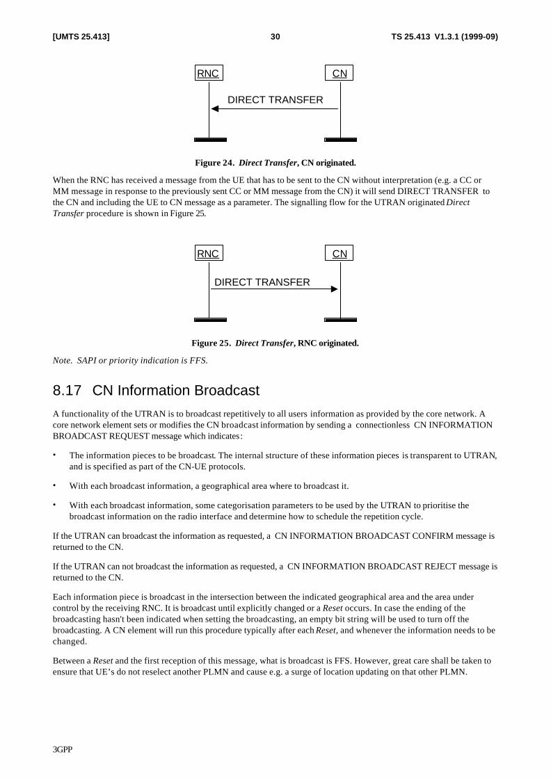
3GPP
TS 25.413 V1.3.1 (1999-09)30[UMTS 25.413]
CNRNC
DIRECT TRANSFER
Figure 24. Direct Transfer, CN originated.
When the RNC has received a message from the UE that has to be sent to the CN without interpretation (e.g. a CC or MM message in response to the previously sent CC or MM message from the CN) it will send DIRECT TRANSFER to the CN and including the UE to CN message as a parameter. The signalling flow for the UTRAN originated Direct Transfer procedure is shown in Figure 25.
CNRNC
DIRECT TRANSFER
Figure 25. Direct Transfer, RNC originated.
Note. SAPI or priority indication is FFS.
8.17 CN Information Broadcast A functionality of the UTRAN is to broadcast repetitively to all users information as provided by the core network. A core network element sets or modifies the CN broadcast information by sending a connectionless CN INFORMATION BROADCAST REQUEST message which indicates:
• The information pieces to be broadcast. The internal structure of these information pieces is transparent to UTRAN, and is specified as part of the CN-UE protocols.
• With each broadcast information, a geographical area where to broadcast it.
• With each broadcast information, some categorisation parameters to be used by the UTRAN to prioritise the broadcast information on the radio interface and determine how to schedule the repetition cycle.
If the UTRAN can broadcast the information as requested, a CN INFORMATION BROADCAST CONFIRM message is returned to the CN.
If the UTRAN can not broadcast the information as requested, a CN INFORMATION BROADCAST REJECT message is returned to the CN.
Each information piece is broadcast in the intersection between the indicated geographical area and the area under control by the receiving RNC. It is broadcast until explicitly changed or a Reset occurs. In case the ending of the broadcasting hasn't been indicated when setting the broadcasting, an empty bit string will be used to turn off the broadcasting. A CN element will run this procedure typically after each Reset, and whenever the information needs to be changed.
Between a Reset and the first reception of this message, what is broadcast is FFS. However, great care shall be taken to ensure that UE’s do not reselect another PLMN and cause e.g. a surge of location updating on that other PLMN.
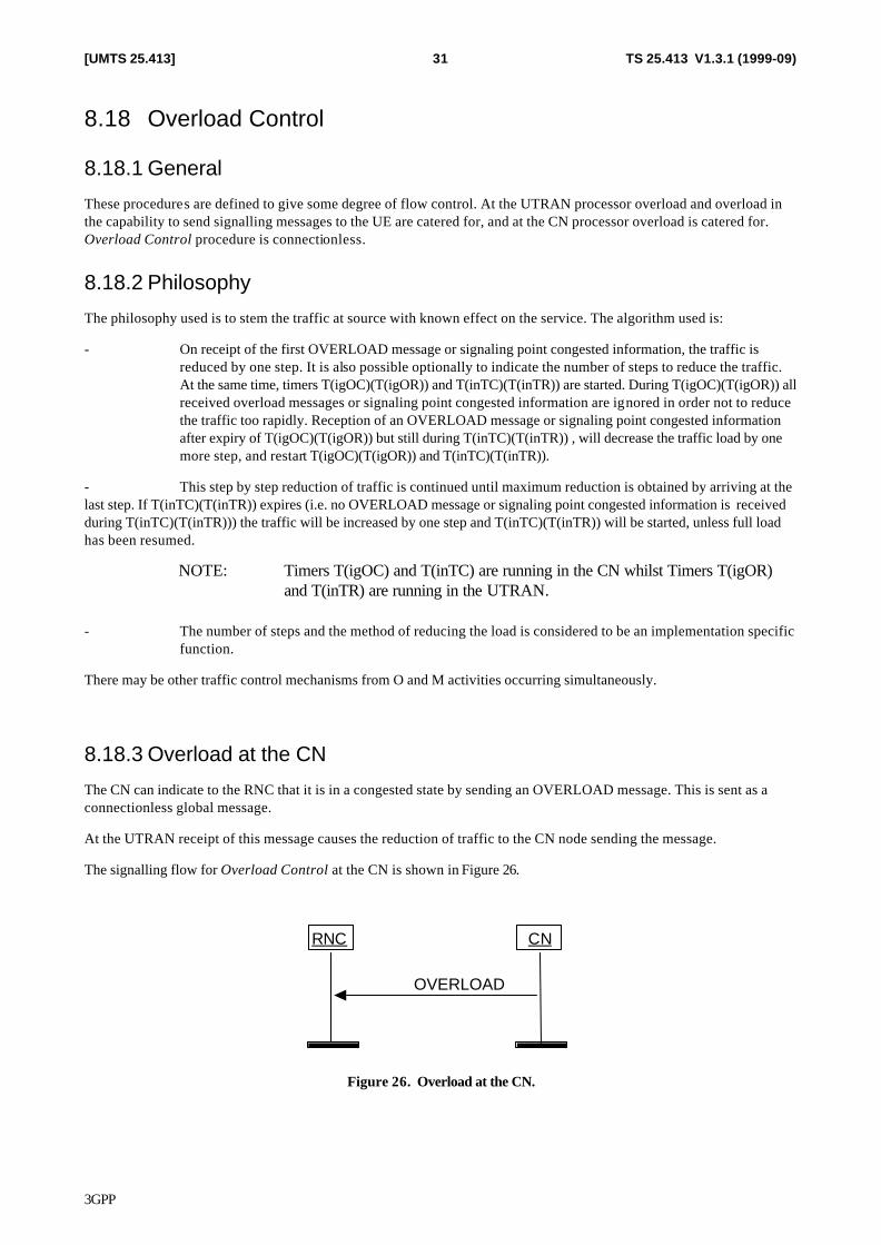
3GPP
TS 25.413 V1.3.1 (1999-09)31[UMTS 25.413]
8.18 Overload Control
8.18.1 General
These procedures are defined to give some degree of flow control. At the UTRAN processor overload and overload in the capability to send signalling messages to the UE are catered for, and at the CN processor overload is catered for. Overload Control procedure is connectionless.
8.18.2 Philosophy
The philosophy used is to stem the traffic at source with known effect on the service. The algorithm used is:
- On receipt of the first OVERLOAD message or signaling point congested information, the traffic is reduced by one step. It is also possible optionally to indicate the number of steps to reduce the traffic. At the same time, timers T(igOC)(T(igOR)) and T(inTC)(T(inTR)) are started. During T(igOC)(T(igOR)) all received overload messages or signaling point congested information are ignored in order not to reduce the traffic too rapidly. Reception of an OVERLOAD message or signaling point congested information after expiry of T(igOC)(T(igOR)) but still during T(inTC)(T(inTR)) , will decrease the traffic load by one more step, and restart T(igOC)(T(igOR)) and T(inTC)(T(inTR)).
- This step by step reduction of traffic is continued until maximum reduction is obtained by arriving at the last step. If T(inTC)(T(inTR)) expires (i.e. no OVERLOAD message or signaling point congested information is received during T(inTC)(T(inTR))) the traffic will be increased by one step and T(inTC)(T(inTR)) will be started, unless full load has been resumed.
NOTE: Timers T(igOC) and T(inTC) are running in the CN whilst Timers T(igOR) and T(inTR) are running in the UTRAN.
- The number of steps and the method of reducing the load is considered to be an implementation specific
function.
There may be other traffic control mechanisms from O and M activities occurring simultaneously.
8.18.3 Overload at the CN
The CN can indicate to the RNC that it is in a congested state by sending an OVERLOAD message. This is sent as a connectionless global message.
At the UTRAN receipt of this message causes the reduction of traffic to the CN node sending the message.
The signalling flow for Overload Control at the CN is shown in Figure 26.
CNRNC
OVERLOAD
Figure 26. Overload at the CN.
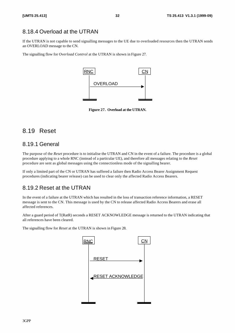
3GPP
TS 25.413 V1.3.1 (1999-09)32[UMTS 25.413]
8.18.4 Overload at the UTRAN
If the UTRAN is not capable to send signalling messages to the UE due to overloaded resources then the UTRAN sends an OVERLOAD message to the CN.
The signalling flow for Overload Control at the UTRAN is shown in Figure 27.
CNRNC
OVERLOAD
Figure 27. Overload at the UTRAN.
8.19 Reset
8.19.1 General
The purpose of the Reset procedure is to initialise the UTRAN and CN in the event of a failure. The procedure is a global procedure applying to a whole RNC (instead of a particular UE), and therefore all messages relating to the Reset procedure are sent as global messages using the connectionless mode of the signalling bearer.
If only a limited part of the CN or UTRAN has suffered a failure then Radio Access Bearer Assignment Request procedures (indicating bearer release) can be used to clear only the affected Radio Access Bearers.
8.19.2 Reset at the UTRAN
In the event of a failure at the UTRAN which has resulted in the loss of transaction reference information, a RESET message is sent to the CN. This message is used by the CN to release affected Radio Access Bearers and erase all affected references.
After a guard period of T(RatR) seconds a RESET ACKNOWLEDGE message is returned to the UTRAN indicating that all references have been cleared.
The signalling flow for Reset at the UTRAN is shown in Figure 28.
CNRNC
RESET
RESET ACKNOWLEDGE
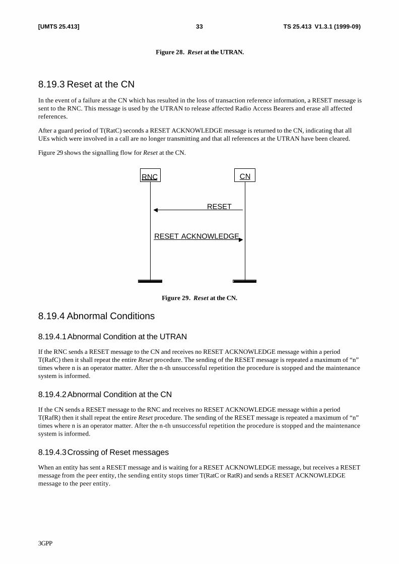
3GPP
TS 25.413 V1.3.1 (1999-09)33[UMTS 25.413]
Figure 28. Reset at the UTRAN.
8.19.3 Reset at the CN
In the event of a failure at the CN which has resulted in the loss of transaction reference information, a RESET message is sent to the RNC. This message is used by the UTRAN to release affected Radio Access Bearers and erase all affected references.
After a guard period of T(RatC) seconds a RESET ACKNOWLEDGE message is returned to the CN, indicating that all UEs which were involved in a call are no longer transmitting and that all references at the UTRAN have been cleared.
Figure 29 shows the signalling flow for Reset at the CN.
CNRNC
RESET
RESET ACKNOWLEDGE
Figure 29. Reset at the CN.
8.19.4 Abnormal Conditions
8.19.4.1 Abnormal Condition at the UTRAN
If the RNC sends a RESET message to the CN and receives no RESET ACKNOWLEDGE message within a period T(RafC) then it shall repeat the entire Reset procedure. The sending of the RESET message is repeated a maximum of “n” times where n is an operator matter. After the n-th unsuccessful repetition the procedure is stopped and the maintenance system is informed.
8.19.4.2 Abnormal Condition at the CN
If the CN sends a RESET message to the RNC and receives no RESET ACKNOWLEDGE message within a period T(RafR) then it shall repeat the entire Reset procedure. The sending of the RESET message is repeated a maximum of “n” times where n is an operator matter. After the n-th unsuccessful repetition the procedure is stopped and the maintenance system is informed.
8.19.4.3 Crossing of Reset messages
When an entity has sent a RESET message and is waiting for a RESET ACKNOWLEDGE message, but receives a RESET message from the peer entity, the sending entity stops timer T(RatC or RatR) and sends a RESET ACKNOWLEDGE message to the peer entity.
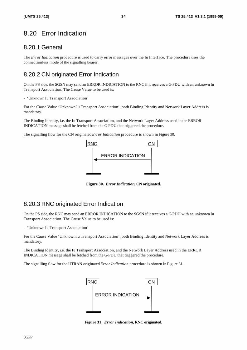
3GPP
TS 25.413 V1.3.1 (1999-09)34[UMTS 25.413]
8.20 Error Indication
8.20.1 General
The Error Indication procedure is used to carry error messages over the Iu Interface. The procedure uses the connectionless mode of the signalling bearer.
8.20.2 CN originated Error Indication
On the PS side, the SGSN may send an ERROR INDICATION to the RNC if it receives a G-PDU with an unknown Iu Transport Association. The Cause Value to be used is:
- ‘Unknown Iu Transport Association’
For the Cause Value ‘Unknown Iu Transport Association’, both Binding Identity and Network Layer Address is mandatory.
The Binding Identity, i.e. the Iu Transport Association, and the Network Layer Address used in the ERROR INDICATION message shall be fetched from the G-PDU that triggered the procedure.
The signalling flow for the CN originated Error Indication procedure is shown in Figure 30.
CNRNC
ERROR INDICATION
Figure 30. Error Indication, CN originated.
8.20.3 RNC originated Error Indication
On the PS side, the RNC may send an ERROR INDICATION to the SGSN if it receives a G-PDU with an unknown Iu Transport Association. The Cause Value to be used is:
- ‘Unknown Iu Transport Association’
For the Cause Value ‘Unknown Iu Transport Association’, both Binding Identity and Network Layer Address is mandatory.
The Binding Identity, i.e. the Iu Transport Association, and the Network Layer Address used in the ERROR INDICATION message shall be fetched from the G-PDU that triggered the procedure.
The signalling flow for the UTRAN originated Error Indication procedure is shown in Figure 31.
CNRNC
ERROR INDICATION
Figure 31. Error Indication, RNC originated.
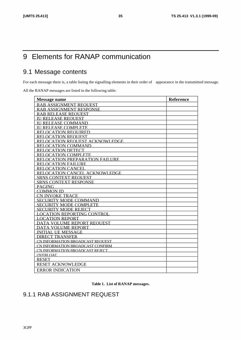
3GPP
TS 25.413 V1.3.1 (1999-09)35[UMTS 25.413]
9 Elements for RANAP communication
9.1 Message contents For each message there is, a table listing the signalling elements in their order of appearance in the transmitted message.
All the RANAP messages are listed in the following table:
Message name Reference RAB ASSIGNMENT REQUEST RAB ASSIGNMENT RESPONSE RAB RELEASE REQUEST IU RELEASE REQUEST IU RELEASE COMMAND IU RELEASE COMPLETE RELOCATION REQUIRED RELOCATION REQUEST RELOCATION REQUEST ACKNOWLEDGE RELOCATION COMMAND RELOCATION DETECT RELOCATION COMPLETE RELOCATION PREPARATION FAILURE RELOCATION FAILURE RELOCATION CANCEL RELOCATION CANCEL ACKNOWLEDGE SRNS CONTEXT REQUEST SRNS CONTEXT RESPONSE PAGING COMMON ID CN INVOKE TRACE SECURITY MODE COMMAND SECURITY MODE COMPLETE SECURITY MODE REJECT LOCATION REPORTING CONTROL LOCATION REPORT DATA VOLUME REPORT REQUEST DATA VOLUME REPORT INITIAL UE MESSAGE DIRECT TRANSFER CN INFORMATION BROADCAST REQUEST CN INFORMATION BROADCAST CONFIRM CN INFORMATION BROADCAST REJECT OVERLOAD RESET RESET ACKNOWLEDGE ERROR INDICATION
Table 1. List of RANAP messages.
9.1.1 RAB ASSIGNMENT REQUEST
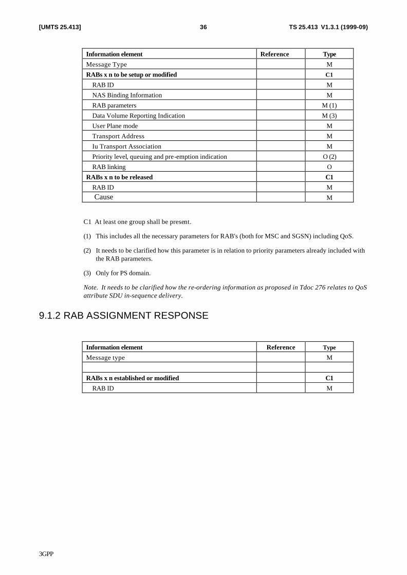
3GPP
TS 25.413 V1.3.1 (1999-09)36[UMTS 25.413]
Information element Reference Type
Message Type M
RABs x n to be setup or modified C1
RAB ID M
NAS Binding Information M
RAB parameters M (1)
Data Volume Reporting Indication M (3)
User Plane mode M
Transport Address M
Iu Transport Association M
Priority level, queuing and pre-emption indication O (2)
RAB linking O
RABs x n to be released C1
RAB ID M Cause M
C1 At least one group shall be present.
(1) This includes all the necessary parameters for RAB's (both for MSC and SGSN) including QoS.
(2) It needs to be clarified how this parameter is in relation to priority parameters already included with the RAB parameters.
(3) Only for PS domain.
Note. It needs to be clarified how the re-ordering information as proposed in Tdoc 276 relates to QoS attribute SDU in-sequence delivery.
9.1.2 RAB ASSIGNMENT RESPONSE
Information element Reference Type
Message type M
RABs x n established or modified C1
RAB ID M
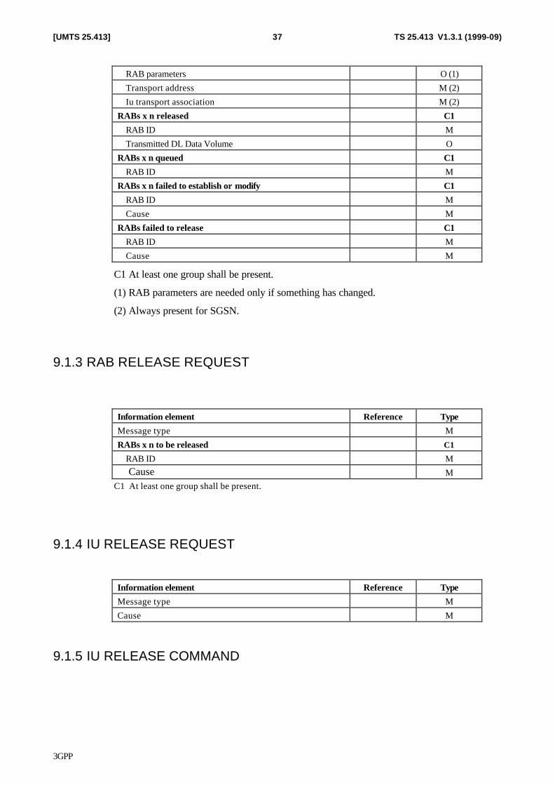
3GPP
TS 25.413 V1.3.1 (1999-09)37[UMTS 25.413]
RAB parameters O (1)
Transport address M (2)
Iu transport association M (2)
RABs x n released C1
RAB ID M
Transmitted DL Data Volume O
RABs x n queued C1
RAB ID M
RABs x n failed to establish or modify C1
RAB ID M
Cause M
RABs failed to release C1
RAB ID M
Cause M
C1 At least one group shall be present.
(1) RAB parameters are needed only if something has changed.
(2) Always present for SGSN.
9.1.3 RAB RELEASE REQUEST
Information element Reference Type
Message type M
RABs x n to be released C1
RAB ID M Cause M
C1 At least one group shall be present.
9.1.4 IU RELEASE REQUEST
Information element Reference Type
Message type M
Cause M
9.1.5 IU RELEASE COMMAND
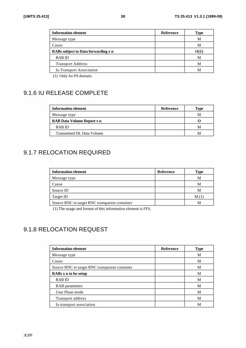
3GPP
TS 25.413 V1.3.1 (1999-09)38[UMTS 25.413]
Information element Reference Type
Message type M
Cause M
RABs subject to Data forwarding x n O(1)
RAB ID M
Transport Address M
Iu Transport Association M (1) Only for PS domain.
9.1.6 IU RELEASE COMPLETE
Information element Reference Type
Message type M
RAB Data Volume Report x n O
RAB ID M
Transmitted DL Data Volume M
9.1.7 RELOCATION REQUIRED
Information element Reference Type
Message type M
Cause M
Source ID M
Target ID M (1)
Source RNC to target RNC transparent container M (1) The usage and format of this information element is FFS.
9.1.8 RELOCATION REQUEST
Information element Reference Type
Message type M
Cause M
Source RNC to target RNC transparent container M
RABs x n to be setup M
RAB ID M
RAB parameters M
User Plane mode M
Transport address M
Iu transport association M
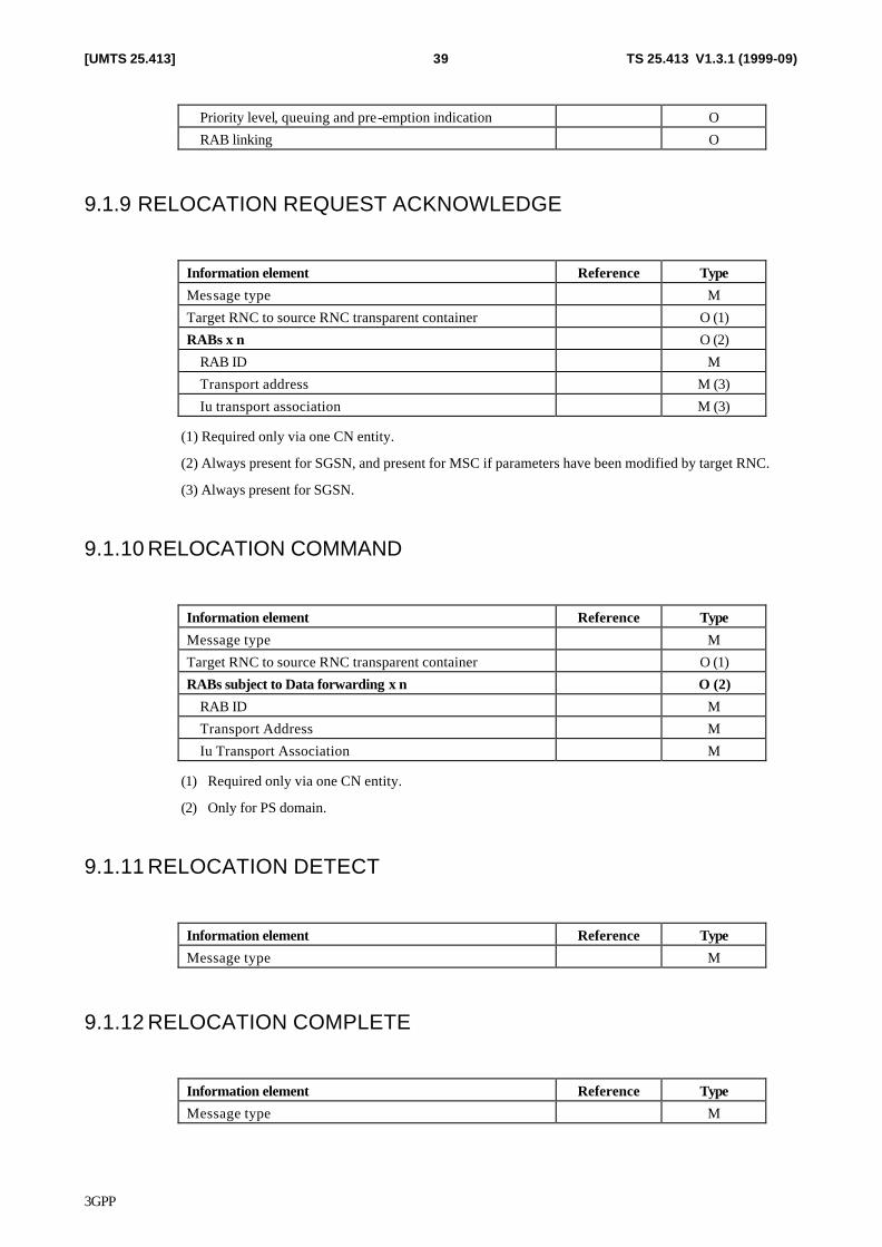
3GPP
TS 25.413 V1.3.1 (1999-09)39[UMTS 25.413]
Priority level, queuing and pre-emption indication O
RAB linking O
9.1.9 RELOCATION REQUEST ACKNOWLEDGE
Information element Reference Type
Message type M
Target RNC to source RNC transparent container O (1)
RABs x n O (2)
RAB ID M
Transport address M (3)
Iu transport association M (3)
(1) Required only via one CN entity.
(2) Always present for SGSN, and present for MSC if parameters have been modified by target RNC.
(3) Always present for SGSN.
9.1.10 RELOCATION COMMAND
Information element Reference Type
Message type M
Target RNC to source RNC transparent container O (1)
RABs subject to Data forwarding x n O (2)
RAB ID M
Transport Address M
Iu Transport Association M
(1) Required only via one CN entity.
(2) Only for PS domain.
9.1.11 RELOCATION DETECT
Information element Reference Type
Message type M
9.1.12 RELOCATION COMPLETE
Information element Reference Type
Message type M
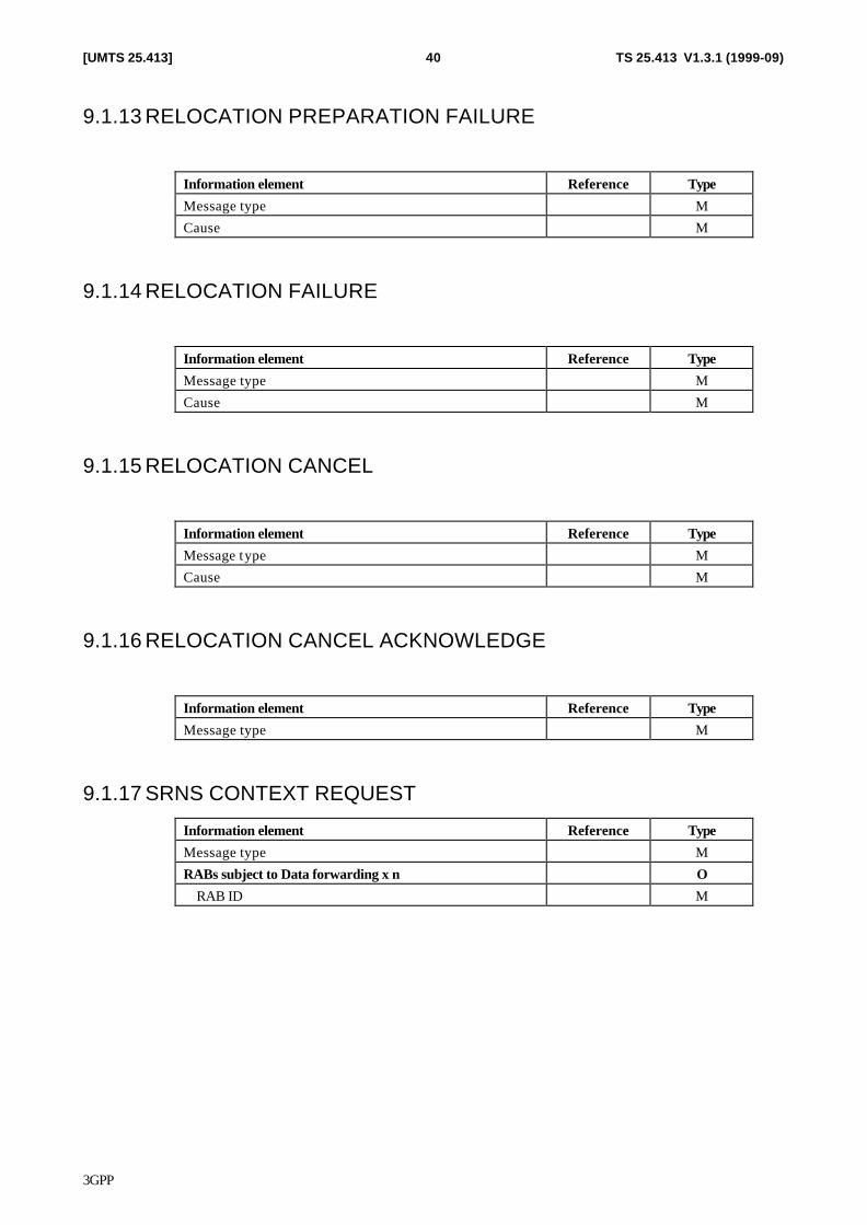
3GPP
TS 25.413 V1.3.1 (1999-09)40[UMTS 25.413]
9.1.13 RELOCATION PREPARATION FAILURE
Information element Reference Type
Message type M
Cause M
9.1.14 RELOCATION FAILURE
Information element Reference Type
Message type M
Cause M
9.1.15 RELOCATION CANCEL
Information element Reference Type
Message type M
Cause M
9.1.16 RELOCATION CANCEL ACKNOWLEDGE
Information element Reference Type
Message type M
9.1.17 SRNS CONTEXT REQUEST
Information element Reference Type
Message type M
RABs subject to Data forwarding x n O
RAB ID M
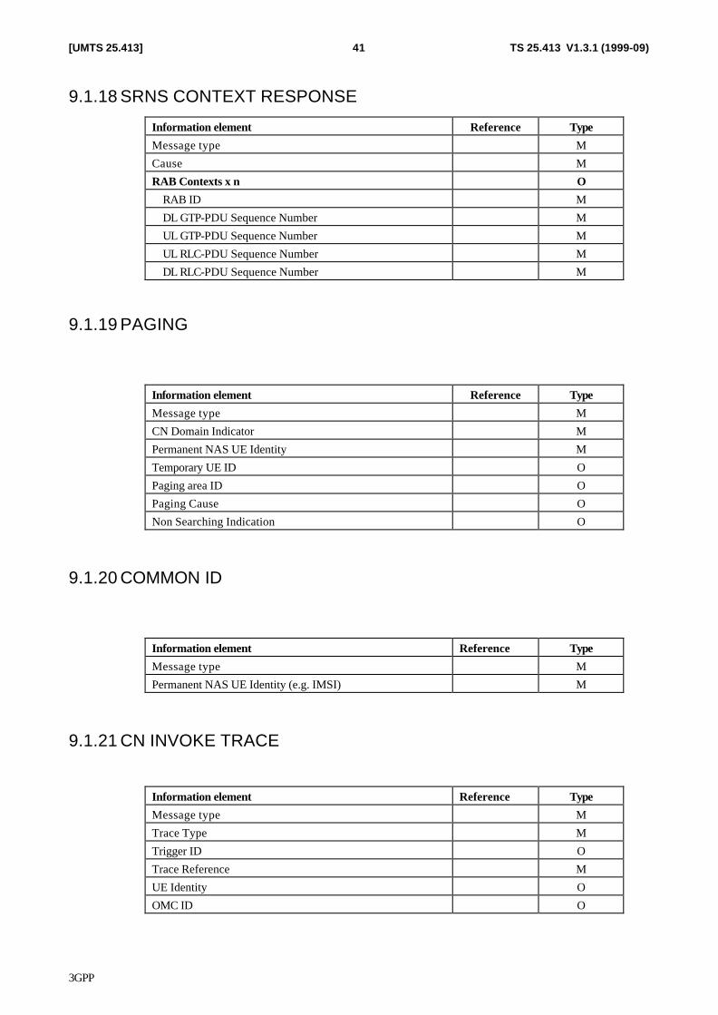
3GPP
TS 25.413 V1.3.1 (1999-09)41[UMTS 25.413]
9.1.18 SRNS CONTEXT RESPONSE
Information element Reference Type
Message type M
Cause M
RAB Contexts x n O
RAB ID M
DL GTP-PDU Sequence Number M
UL GTP-PDU Sequence Number M
UL RLC-PDU Sequence Number M
DL RLC-PDU Sequence Number M
9.1.19 PAGING
Information element Reference Type
Message type M
CN Domain Indicator M
Permanent NAS UE Identity M
Temporary UE ID O
Paging area ID O
Paging Cause O
Non Searching Indication O
9.1.20 COMMON ID
Information element Reference Type
Message type M
Permanent NAS UE Identity (e.g. IMSI) M
9.1.21 CN INVOKE TRACE
Information element Reference Type
Message type M
Trace Type M
Trigger ID O
Trace Reference M
UE Identity O
OMC ID O
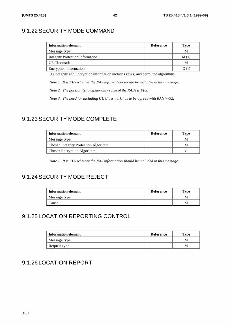
3GPP
TS 25.413 V1.3.1 (1999-09)42[UMTS 25.413]
9.1.22 SECURITY MODE COMMAND
Information element Reference Type
Message type M
Integrity Protection Information M (1)
UE Classmark M
Encryption Information O (1) (1) Integrity and Encryption information includes key(s) and permitted algorithms.
Note 1. It is FFS whether the NAS information should be included in this message.
Note 2. The possibility to cipher only some of the RABs is FFS.
Note 3. The need for including UE Classmark has to be agreed with RAN WG2.
9.1.23 SECURITY MODE COMPLETE
Information element Reference Type
Message type M
Chosen Integrity Protection Algorithm M
Chosen Encryption Algorithm O
Note 1. It is FFS whether the NAS information should be included in this message.
9.1.24 SECURITY MODE REJECT
Information element Reference Type
Message type M
Cause M
9.1.25 LOCATION REPORTING CONTROL
Information element Reference Type
Message type M
Request type M
9.1.26 LOCATION REPORT
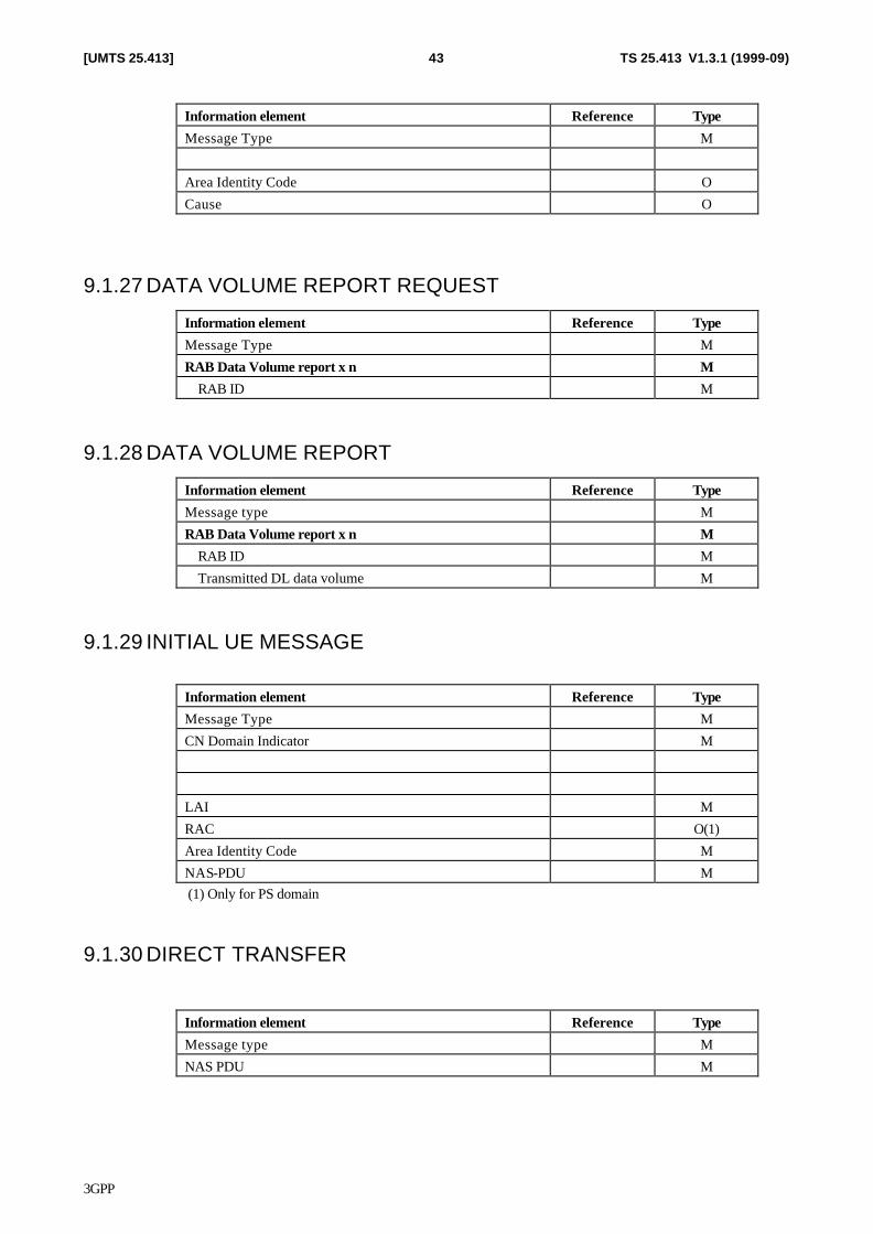
3GPP
TS 25.413 V1.3.1 (1999-09)43[UMTS 25.413]
Information element Reference Type
Message Type M
Area Identity Code O
Cause O
9.1.27 DATA VOLUME REPORT REQUEST
Information element Reference Type
Message Type M
RAB Data Volume report x n M
RAB ID M
9.1.28 DATA VOLUME REPORT
Information element Reference Type
Message type M
RAB Data Volume report x n M
RAB ID M
Transmitted DL data volume M
9.1.29 INITIAL UE MESSAGE
Information element Reference Type
Message Type M
CN Domain Indicator M
LAI M
RAC O(1)
Area Identity Code M
NAS-PDU M (1) Only for PS domain
9.1.30 DIRECT TRANSFER
Information element Reference Type
Message type M
NAS PDU M
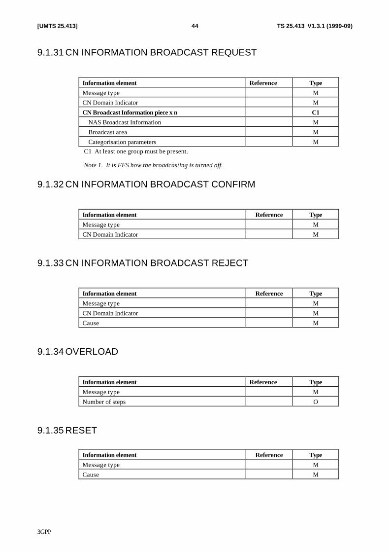
3GPP
TS 25.413 V1.3.1 (1999-09)44[UMTS 25.413]
9.1.31 CN INFORMATION BROADCAST REQUEST
Information element Reference Type
Message type M
CN Domain Indicator M
CN Broadcast Information piece x n C1
NAS Broadcast Information M
Broadcast area M
Categorisation parameters M C1 At least one group must be present.
Note 1. It is FFS how the broadcasting is turned off.
9.1.32 CN INFORMATION BROADCAST CONFIRM
Information element Reference Type
Message type M
CN Domain Indicator M
9.1.33 CN INFORMATION BROADCAST REJECT
Information element Reference Type
Message type M
CN Domain Indicator M
Cause M
9.1.34 OVERLOAD
Information element Reference Type
Message type M
Number of steps O
9.1.35 RESET
Information element Reference Type
Message type M
Cause M
3GPP
TS 25.413 V1.3.1 (1999-09)45[UMTS 25.413]
9.1.36 RESET ACKNOWLEDGE
Information element Reference Type
Message type M
CN Domain Indicator M
9.1.37 ERROR INDICATION
Information element Reference Type
Message type M
CN Domain Indicator M
Cause M
Binding ID O
Source Network Layer Address O
9.2 Information element definitions [Study item 7: Usage of ASN.1 and encoding rules versus the description of information elements in TTC/ARIB document.]
9.2.1 Radio network layer related IEs
9.2.1.1 Message Type
Message type uniquely identifies the message being sent. It is mandatory for all messages.
9.2.1.2 RAB ID
[Editor's note: This definition needs to be harmonized with UMTS 23.10.]
This element uniquely identifies the radio access bearer over one Iu connection. The radio access bearer identification has only local significance in one Iu connection. The RAB ID shall remain the same for the duration of the RAB.
9.2.1.3 RAB parameters
The purpose of the RAB parameter information element is to indicate all RAB parameters for both directions, e.g. Quality of service (QoS) classes.
9.2.1.4 Cause
The cause element is used to indicate the reason for a particular event to have occurred according to the cause code list.
9.2.1.5 Priority level, queuing and pre-emption indication
The Priority level indicates the priority of the request. The pre-emption indicator may (alone or along with the priority level) be used to manage the queueing, pre-emption and priority function.
3GPP
TS 25.413 V1.3.1 (1999-09)46[UMTS 25.413]
9.2.1.6 RAB linking
This element is a common reference shared by a set of RABs which must be treated together as requested.
9.2.1.7 CN Domain Indicator
Indicates the CN domain from which the message originates or to which the message shall be sent.
9.2.1.8 Trace Type
A fixed length element indicating the type of trace information to be recorded.
9.2.1.9 Trigger ID
A variable length element indicating the identity of the entity which initiated the trace.
9.2.1.10 Trace Reference
A fixed length element providing a trace reference number allocated by the triggering entity.
9.2.1.11 UE Identity
This element identifies the element to be traced i.e. the subscriber or the user equipment.
9.2.1.12 OMC ID
A variable length element indicating the destination address of the Operation and Maintenance Center (OMC) to which trace information is to be sent.
9.2.1.13 Integrity Protection Information
9.2.1.14 Encryption Information
This element contains the user data encryption information (key(s) and permitted algorithms) used to control any encryption equipment at the RNC.
9.2.1.15 UE Classmark
9.2.1.16 Chosen Integrity Protection Algorithm
9.2.1.17 Chosen Encryption Algorithm
This element indicates the encryption algorithm being used by the RNC.
9.2.1.18 Broadcast Area
With each NAS Broadcast Information, this element identifies the geographical area where to broadcast it.
3GPP
TS 25.413 V1.3.1 (1999-09)47[UMTS 25.413]
9.2.1.19 Categorisation parameters
With each NAS Broadcast Information, this element is used by the RNC to determine how to prioritise the information and schedule the repetition cycle.
9.2.1.20 Request Type
[Editor's note: This definition needs to be harmonized with UMTS 23.10.]
This information request the information type that to be reported from RNC, e.g. to report LAI and RAI of the current UE location. Other request types are FFS.
9.2.1.21 Data Volume Reporting Indication
This information element indicates whether or not RNC has to calculate the successfully transmitted NAS data amount for the RAB and to report the amount of data when the RAB is released.
9.2.1.22 User Plane Mode
This element indicates the mode of operation of the Iu User plane requested for realising the RAB. The Iu user plane modes are defined in UMTS 25.415.
9.2.1.23 Paging Area ID
This element uniquely identifies the area, where the PAGING message shall be broadcasted. The Paging area ID may be e.g. a Location Area ID or Routing Area ID.
9.2.1.24 Non Searching Indication
This parameter allows the RNC not to search Common ID when receiving a PAGING message from the CN.
9.2.1.25 Source ID
Source ID identifies the source for the relocation of SRNS. The Source ID may be e.g. Source RNC-ID or serving cell ID.
9.2.1.26 Target ID
Target ID identifies the target for the relocation of SRNS. The target ID may be e.g. Target RNC-ID (for UMTS-UMTS relocation) or Cell Global ID of the relocation target (in case of UMTS to GSM relocation).
9.2.1.27 Source RNC to Target RNC Transparent Container
Source RNC to Target RNC Transparent Container IE is an information element that is produced by Source RNC and is transmitted to target RNC. In inter system relocation the IE is transmitted either from external relocation source to target RNC or from source RNC to the external relocation target.
This IE is transparent to CN.
9.2.1.28 Target RNC to Source RNC Transparent Container
Target RNC to Source RNC Transparent Container IE is an information element that is produced by Target RNC and is transmitted to Source RNC. In inter system relocation the IE is transmitted either from external relocation target to source RNC or from target RNC to the external relocation source.
This IE is transparent to CN.
9.2.1.29 Number of steps
Indicates the number of steps to reduce traffic in overload situation.
3GPP
TS 25.413 V1.3.1 (1999-09)48[UMTS 25.413]
9.2.1.30 DL GTP-PDU Sequence Number
This IE indicates the sequence number of the GTP-PDU which is the next to be sent to the UE.
9.2.1.31 UL GTP-PDU Sequence Number
This IE indicates the sequence number of the GTP-PDU which is the next to be sent to the SGSN.
9.2.1.32 UL RLC-PDU Sequence Number
This IE indicates the sequence number of the UL RLC-PDU which carried the last segment of the last GTP-PDU forwarded to SGSN.
9.2.1.33 DL RLC-PDU Sequence Number
This IE indicates the sequence number of the DL RLC-PDU which carried the last segment of the last N-PDU to the UE.
9.2.2 Transport network layer related IEs
9.2.2.1 Transport address
For the PS domain this information element is an IP address to be used for the user plane transport. For the CS domain this address is to be used for Transport Network Control Plane signalling to set up the U-Plane connection.
9.2.2.2 Iu transport association
This element is used to associate the RAB and the corresponding user plane connection. For the CS domain this information element is the Binding Id to be used in Transport Network Control Plane signalling during set up of the U-Plane connection. In PS domain this information element is the GTP Tunnel Endpoint Identifier.
9.2.3 NAS related IEs
9.2.3.1 NAS Binding Information
This element contains application specific information, to be used by the remote NAS entity at the UE side. It serves as the binding to a NAS call. This element is transparent to the RNC.
9.2.3.2 Permanent NAS Identity
This element is used to identify the UE commonly in UTRAN and in CN. RNC uses to find other existing signalling connections of this same UE (e.g. RRC or Iu signalling connections) Initially this is of the type of IMSI. The future type is FFS.
Note: IMSI is specified in the TS 23.003.
9.2.3.3 Temporary UE ID
Temporary Mobile Subscriber Identity, used for security reasons to hide the identity of a subscriber.
9.2.3.4 Paging Cause
This element indicates the cause of paging to the UE.
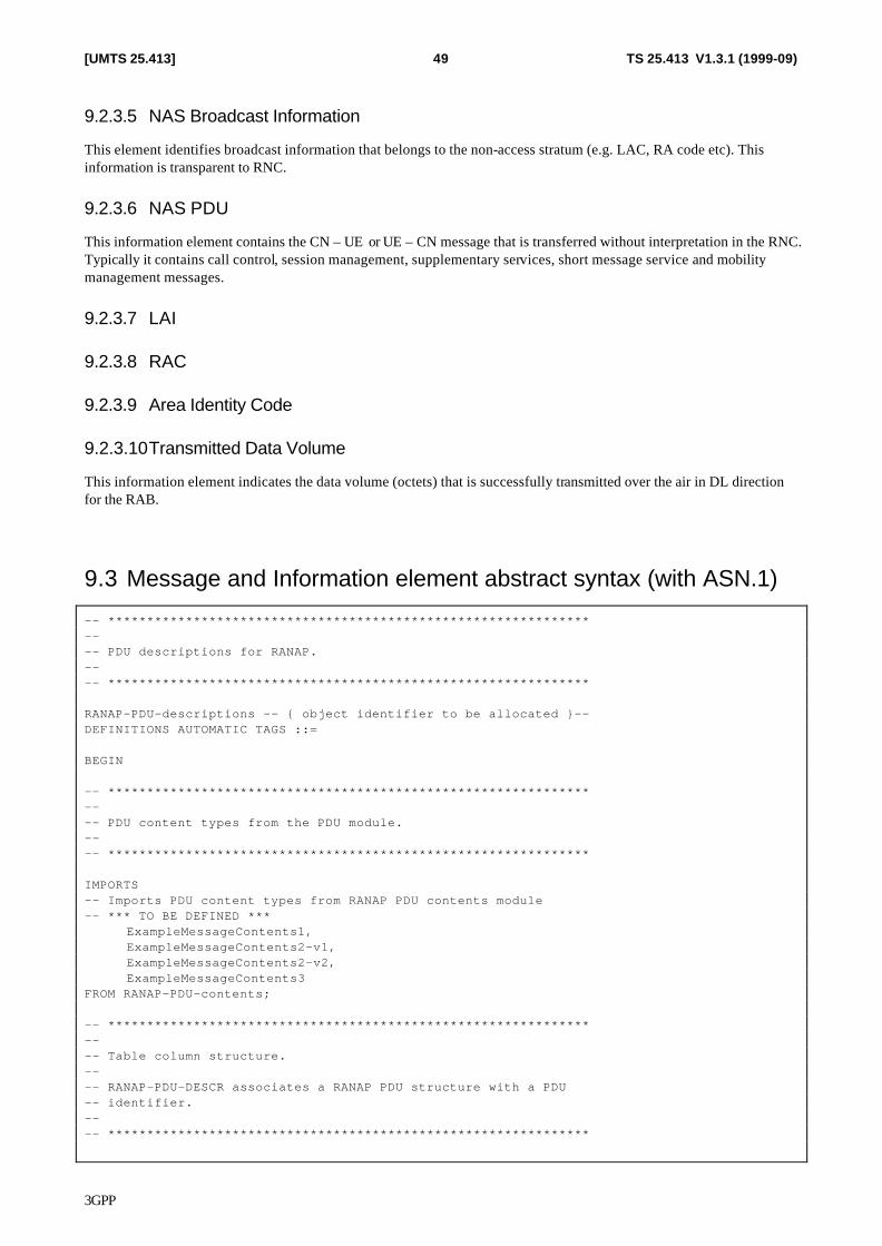
3GPP
TS 25.413 V1.3.1 (1999-09)49[UMTS 25.413]
9.2.3.5 NAS Broadcast Information
This element identifies broadcast information that belongs to the non-access stratum (e.g. LAC, RA code etc). This information is transparent to RNC.
9.2.3.6 NAS PDU
This information element contains the CN – UE or UE – CN message that is transferred without interpretation in the RNC. Typically it contains call control, session management, supplementary services, short message service and mobility management messages.
9.2.3.7 LAI
9.2.3.8 RAC
9.2.3.9 Area Identity Code
9.2.3.10 Transmitted Data Volume
This information element indicates the data volume (octets) that is successfully transmitted over the air in DL direction for the RAB.
9.3 Message and Information element abstract syntax (with ASN.1)
-- ************************************************************** -- -- PDU descriptions for RANAP. -- -- ************************************************************** RANAP-PDU-descriptions -- { object identifier to be allocated }-- DEFINITIONS AUTOMATIC TAGS ::= BEGIN -- ************************************************************** -- -- PDU content types from the PDU module. -- -- ************************************************************** IMPORTS -- Imports PDU content types from RANAP PDU contents module -- *** TO BE DEFINED *** ExampleMessageContents1, ExampleMessageContents2-v1, ExampleMessageContents2-v2, ExampleMessageContents3 FROM RANAP-PDU-contents; -- ************************************************************** -- -- Table column structure. -- -- RANAP-PDU-DESCR associates a RANAP PDU structure with a PDU -- identifier. -- -- **************************************************************
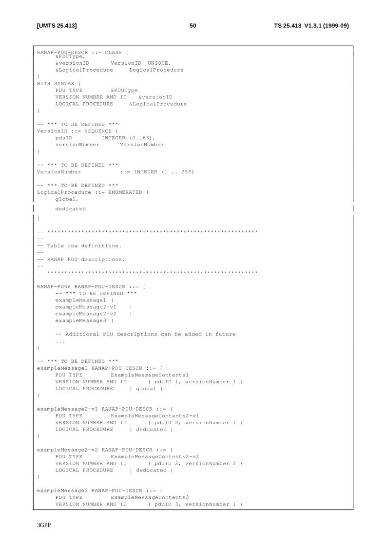
3GPP
TS 25.413 V1.3.1 (1999-09)50[UMTS 25.413]
RANAP-PDU-DESCR ::= CLASS { &PDUType, &versionID VersionID UNIQUE, &LogicalProcedure LogicalProcedure } WITH SYNTAX { PDU TYPE &PDUType VERSION NUMBER AND ID &versionID LOGICAL PROCEDURE &LogicalProcedure } -- *** TO BE DEFINED *** VersionID ::= SEQUENCE { pduID INTEGER (0..63), versionNumber VersionNumber } -- *** TO BE DEFINED *** VersionNumber ::= INTEGER (1 .. 255) -- *** TO BE DEFINED *** LogicalProcedure ::= ENUMERATED { global,
dedicated
} -- ************************************************************** -- -- Table row definitions. -- -- RANAP PDU descriptions. -- -- ************************************************************** RANAP-PDUs RANAP-PDU-DESCR ::= { -- *** TO BE DEFINED *** exampleMessage1 | exampleMessage2-v1 | exampleMessage2-v2 | exampleMessage3 | -- Additional PDU descriptions can be added in future ... } -- *** TO BE DEFINED *** exampleMessage1 RANAP-PDU-DESCR ::= { PDU TYPE ExampleMessageContents1 VERSION NUMBER AND ID { pduID 1, versionNumber 1 } LOGICAL PROCEDURE { global } } exampleMessage2-v1 RANAP-PDU-DESCR ::= { PDU TYPE ExampleMessageContents2-v1 VERSION NUMBER AND ID { pduID 2, versionNumber 1 } LOGICAL PROCEDURE { dedicated } } exampleMessage2-v2 RANAP-PDU-DESCR ::= { PDU TYPE ExampleMessageContents2-v2 VERSION NUMBER AND ID { pduID 2, versionNumber 2 } LOGICAL PROCEDURE { dedicated } } exampleMessage3 RANAP-PDU-DESCR ::= { PDU TYPE ExampleMessageContents3 VERSION NUMBER AND ID { pduID 3, versionNumber 1 }
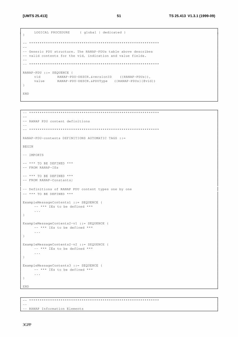
3GPP
TS 25.413 V1.3.1 (1999-09)51[UMTS 25.413]
LOGICAL PROCEDURE { global | dedicated } } -- ************************************************************** -- -- Generic PDU structure. The RANAP-PDUs table above describes -- valid contents for the vid, indication and value fields. -- -- ************************************************************** RANAP-PDU ::= SEQUENCE { vid RANAP-PDU-DESCR.&versionID ({RANAP-PDUs}), value RANAP-PDU-DESCR.&PDUType ({RANAP-PDUs}{@vid}) } END
-- ************************************************************** -- -- RANAP PDU content definitions -- -- ************************************************************** RANAP-PDU-contents DEFINITIONS AUTOMATIC TAGS ::= BEGIN -- IMPORTS -- *** TO BE DEFINED *** -- FROM RANAP-IEs -- *** TO BE DEFINED *** -- FROM RANAP-Constants; -- Definitions of RANAP PDU content types one by one -- *** TO BE DEFINED *** ExampleMessageContents1 ::= SEQUENCE { -- *** IEs to be defined *** ... } ExampleMessageContents2-v1 ::= SEQUENCE { -- *** IEs to be defined *** ... } ExampleMessageContents2-v2 ::= SEQUENCE { -- *** IEs to be defined *** ... } ExampleMessageContents3 ::= SEQUENCE { -- *** IEs to be defined *** ... } END
-- ************************************************************** -- -- RANAP Information Elements
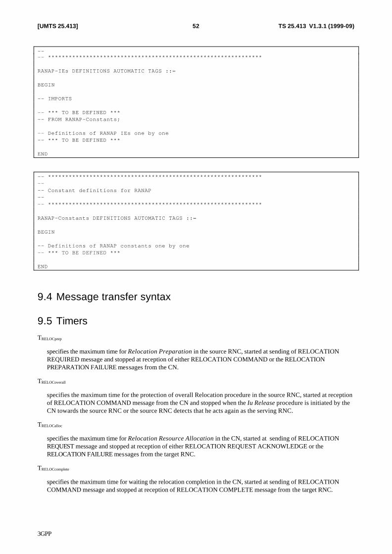
3GPP
TS 25.413 V1.3.1 (1999-09)52[UMTS 25.413]
-- -- ************************************************************** RANAP-IEs DEFINITIONS AUTOMATIC TAGS ::= BEGIN -- IMPORTS -- *** TO BE DEFINED *** -- FROM RANAP-Constants; -- Definitions of RANAP IEs one by one -- *** TO BE DEFINED *** END
-- ************************************************************** -- -- Constant definitions for RANAP -- -- ************************************************************** RANAP-Constants DEFINITIONS AUTOMATIC TAGS ::= BEGIN -- Definitions of RANAP constants one by one -- *** TO BE DEFINED *** END
9.4 Message transfer syntax
9.5 Timers TRELOCprep
specifies the maximum time for Relocation Preparation in the source RNC, started at sending of RELOCATION REQUIRED message and stopped at reception of either RELOCATION COMMAND or the RELOCATION PREPARATION FAILURE messages from the CN.
TRELOCoverall
specifies the maximum time for the protection of overall Relocation procedure in the source RNC, started at reception of RELOCATION COMMAND message from the CN and stopped when the Iu Release procedure is initiated by the CN towards the source RNC or the source RNC detects that he acts again as the serving RNC.
TRELOCalloc
specifies the maximum time for Relocation Resource Allocation in the CN, started at sending of RELOCATION REQUEST message and stopped at reception of either RELOCATION REQUEST ACKNOWLEDGE or the RELOCATION FAILURE messages from the target RNC.
TRELOCcomplete
specifies the maximum time for waiting the relocation completion in the CN, started at sending of RELOCATION COMMAND message and stopped at reception of RELOCATION COMPLETE message from the target RNC.
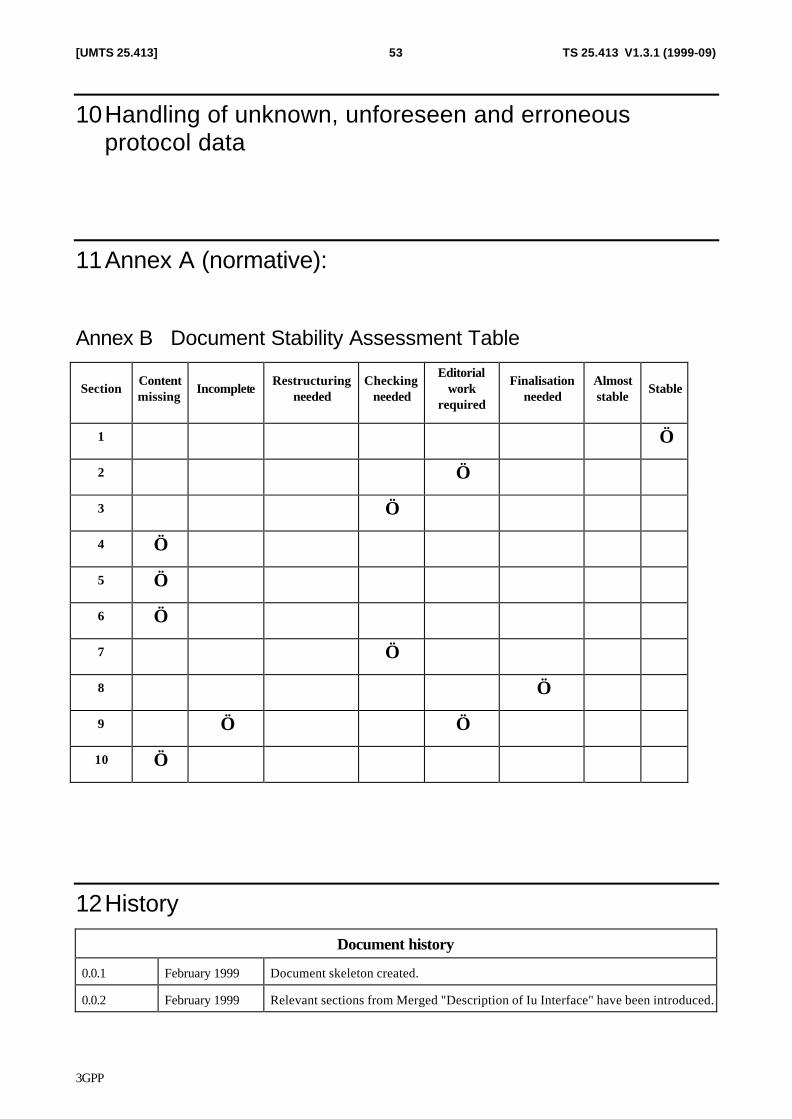
3GPP
TS 25.413 V1.3.1 (1999-09)53[UMTS 25.413]
10 Handling of unknown, unforeseen and erroneous protocol data
11 Annex A (normative):
Annex B Document Stability Assessment Table
Section Content missing
Incomplete Restructuring
needed Checking
needed
Editorial work
required
Finalisation needed
Almost stable
Stable
1 √
2 √
3 √
4 √
5 √
6 √
7 √
8 √
9 √ √
10 √
12 History
Document history
0.0.1 February 1999 Document skeleton created.
0.0.2 February 1999 Relevant sections from Merged "Description of Iu Interface" have been introduced.
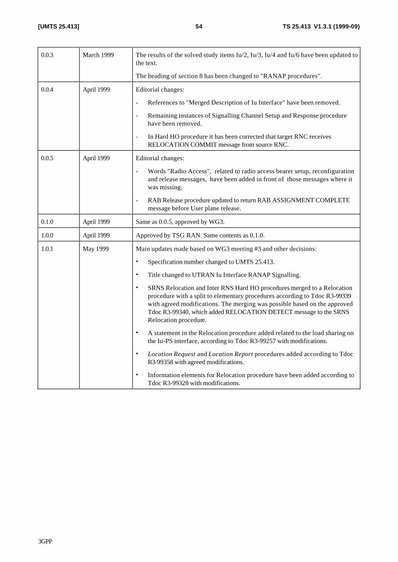
3GPP
TS 25.413 V1.3.1 (1999-09)54[UMTS 25.413]
0.0.3 March 1999 The results of the solved study items Iu/2, Iu/3, Iu/4 and Iu/6 have been updated to the text.
The heading of section 8 has been changed to "RANAP procedures".
0.0.4 April 1999 Editorial changes:
- References to "Merged Description of Iu Interface" have been removed.
- Remaining instances of Signalling Channel Setup and Response procedure have been removed.
- In Hard HO procedure it has been corrected that target RNC receives RELOCATION COMMIT message from source RNC.
0.0.5 April 1999 Editorial changes:
- Words "Radio Access", related to radio access bearer setup, reconfiguration and release messages, have been added in front of those messages where it was missing.
- RAB Release procedure updated to return RAB ASSIGNMENT COMPLETE message before User plane release.
0.1.0 April 1999 Same as 0.0.5, approved by WG3.
1.0.0 April 1999 Approved by TSG RAN. Same contents as 0.1.0.
1.0.1 May 1999 Main updates made based on WG3 meeting #3 and other decisions:
• Specification number changed to UMTS 25.413.
• Title changed to UTRAN Iu Interface RANAP Signalling.
• SRNS Relocation and Inter RNS Hard HO procedures merged to a Relocation procedure with a split to elementary procedures according to Tdoc R3-99339 with agreed modifications. The merging was possible based on the approved Tdoc R3-99340, which added RELOCATION DETECT message to the SRNS Relocation procedure.
• A statement in the Relocation procedure added related to the load sharing on the Iu-PS interface, according to Tdoc R3-99257 with modifications.
• Location Request and Location Report procedures added according to Tdoc R3-99358 with agreed modifications.
• Information elements for Relocation procedure have been added according to Tdoc R3-99328 with modifications.
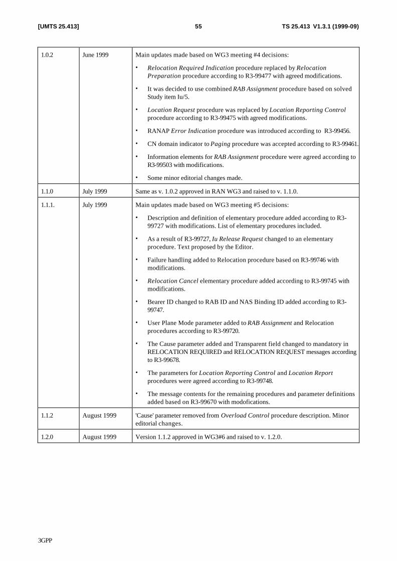
3GPP
TS 25.413 V1.3.1 (1999-09)55[UMTS 25.413]
1.0.2 June 1999 Main updates made based on WG3 meeting #4 decisions:
• Relocation Required Indication procedure replaced by Relocation Preparation procedure according to R3-99477 with agreed modifications.
• It was decided to use combined RAB Assignment procedure based on solved Study item Iu/5.
• Location Request procedure was replaced by Location Reporting Control procedure according to R3-99475 with agreed modifications.
• RANAP Error Indication procedure was introduced according to R3-99456.
• CN domain indicator to Paging procedure was accepted according to R3-99461.
• Information elements for RAB Assignment procedure were agreed according to R3-99503 with modifications.
• Some minor editorial changes made.
1.1.0 July 1999 Same as v. 1.0.2 approved in RAN WG3 and raised to v. 1.1.0.
1.1.1. July 1999 Main updates made based on WG3 meeting #5 decisions:
• Description and definition of elementary procedure added according to R3-99727 with modifications. List of elementary procedures included.
• As a result of R3-99727, Iu Release Request changed to an elementary procedure. Text proposed by the Editor.
• Failure handling added to Relocation procedure based on R3-99746 with modifications.
• Relocation Cancel elementary procedure added according to R3-99745 with modifications.
• Bearer ID changed to RAB ID and NAS Binding ID added according to R3-99747.
• User Plane Mode parameter added to RAB Assignment and Relocation procedures according to R3-99720.
• The Cause parameter added and Transparent field changed to mandatory in RELOCATION REQUIRED and RELOCATION REQUEST messages according to R3-99678.
• The parameters for Location Reporting Control and Location Report procedures were agreed according to R3-99748.
• The message contents for the remaining procedures and parameter definitions added based on R3-99670 with modofications.
1.1.2 August 1999 'Cause' parameter removed from Overload Control procedure description. Minor editorial changes.
1.2.0 August 1999 Version 1.1.2 approved in WG3#6 and raised to v. 1.2.0.
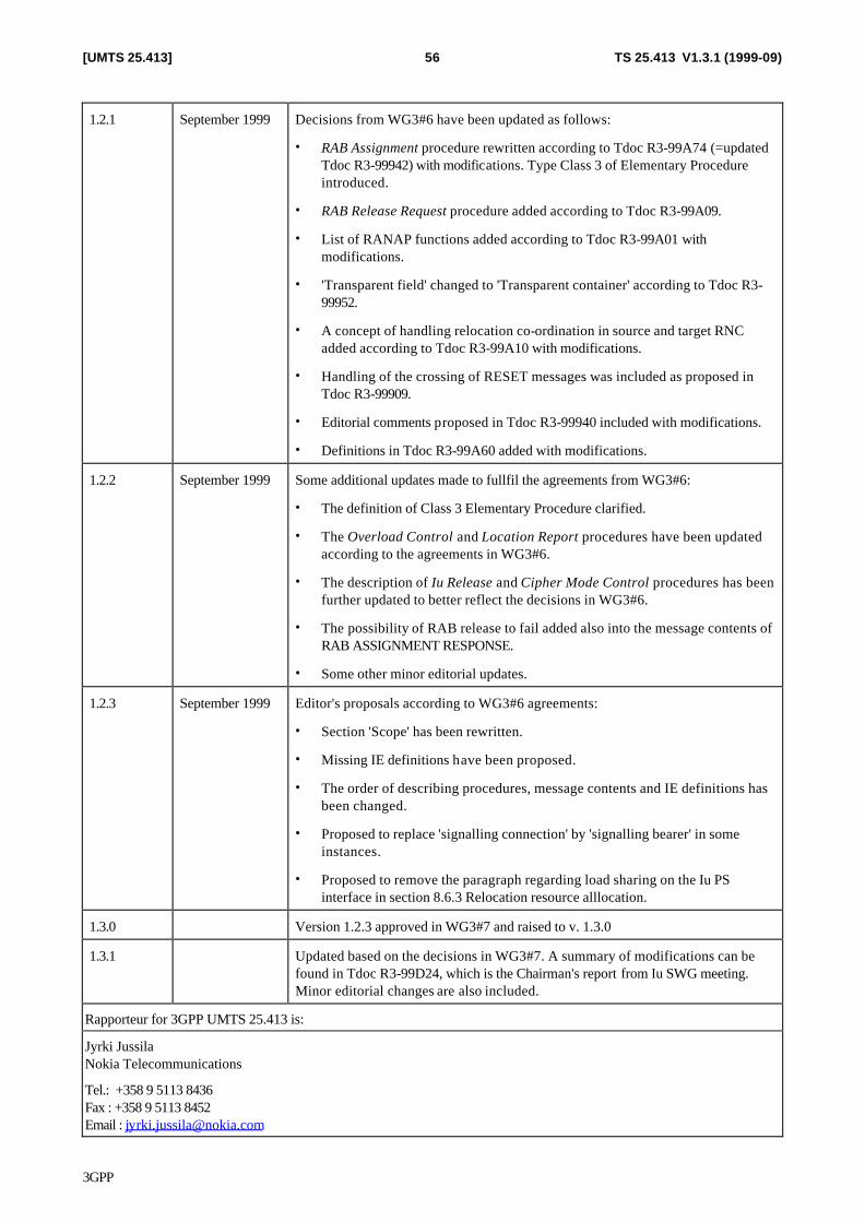
3GPP
TS 25.413 V1.3.1 (1999-09)56[UMTS 25.413]
1.2.1 September 1999 Decisions from WG3#6 have been updated as follows:
• RAB Assignment procedure rewritten according to Tdoc R3-99A74 (=updated Tdoc R3-99942) with modifications. Type Class 3 of Elementary Procedure introduced.
• RAB Release Request procedure added according to Tdoc R3-99A09.
• List of RANAP functions added according to Tdoc R3-99A01 with modifications.
• 'Transparent field' changed to 'Transparent container' according to Tdoc R3-99952.
• A concept of handling relocation co-ordination in source and target RNC added according to Tdoc R3-99A10 with modifications.
• Handling of the crossing of RESET messages was included as proposed in Tdoc R3-99909.
• Editorial comments proposed in Tdoc R3-99940 included with modifications.
• Definitions in Tdoc R3-99A60 added with modifications.
1.2.2 September 1999 Some additional updates made to fullfil the agreements from WG3#6:
• The definition of Class 3 Elementary Procedure clarified.
• The Overload Control and Location Report procedures have been updated according to the agreements in WG3#6.
• The description of Iu Release and Cipher Mode Control procedures has been further updated to better reflect the decisions in WG3#6.
• The possibility of RAB release to fail added also into the message contents of RAB ASSIGNMENT RESPONSE.
• Some other minor editorial updates.
1.2.3 September 1999 Editor's proposals according to WG3#6 agreements:
• Section 'Scope' has been rewritten.
• Missing IE definitions have been proposed.
• The order of describing procedures, message contents and IE definitions has been changed.
• Proposed to replace 'signalling connection' by 'signalling bearer' in some instances.
• Proposed to remove the paragraph regarding load sharing on the Iu PS interface in section 8.6.3 Relocation resource alllocation.
1.3.0 Version 1.2.3 approved in WG3#7 and raised to v. 1.3.0
1.3.1 Updated based on the decisions in WG3#7. A summary of modifications can be found in Tdoc R3-99D24, which is the Chairman's report from Iu SWG meeting. Minor editorial changes are also included.
Rapporteur for 3GPP UMTS 25.413 is:
Jyrki Jussila Nokia Telecommunications
Tel.: +358 9 5113 8436 Fax : +358 9 5113 8452 Email : [email protected]

3GPP
TS 25.413 V1.3.1 (1999-09)57[UMTS 25.413]
This document is written in Microsoft Word version 7.0/96.