Technical Report - 株式会社QT · Technical Report 3rd Generation ... 6.2.2.4 Fault Management...
41
3GPP TR 32.821 V9.0.0 (2009-06) Technical Report 3rd Generation Partnership Project; Technical Specification Group Services and System Aspects; Telecommunication management; Study of Self-Organizing Networks (SON) related Operations, Administration and Maintenance (OAM) for Home Node B (HNB) (Release 9) The present document has been developed within the 3 rd Generation Partnership Project (3GPP TM ) and may be further elaborated for the purposes of 3GPP. The present document has not been subject to any approval process by the 3GPP Organizational Partners and shall not be implemented. This Specification is provided for future development work within 3GPP only. The Organizational Partners accept no liability for any use of this Specification. Specifications and reports for implementation of the 3GPP TM system should be obtained via the 3GPP Organizational Partners' Publications Offices.
Transcript of Technical Report - 株式会社QT · Technical Report 3rd Generation ... 6.2.2.4 Fault Management...
3GPP TR 32.821 V9.0.0 (2009-06) Technical Report
3rd Generation Partnership Project; Technical Specification Group Services and System Aspects;
Telecommunication management; Study of Self-Organizing Networks (SON) related
Operations, Administration and Maintenance (OAM) for Home Node B (HNB)
(Release 9)
The present document has been developed within the 3rd Generation Partnership Project (3GPP TM) and may be further elaborated for the purposes of 3GPP. The present document has not been subject to any approval process by the 3GPP Organizational Partners and shall not be implemented. This Specification is provided for future development work within 3GPP only. The Organizational Partners accept no liability for any use of this Specification. Specifications and reports for implementation of the 3GPP TM system should be obtained via the 3GPP Organizational Partners' Publications Offices.

3GPP
3GPP TR 32.821 V9.0.0 (2009-06) 2 Release 9
Keywords UMTS, management, network
3GPP
Postal address
3GPP support office address 650 Route des Lucioles - Sophia Antipolis
Valbonne - FRANCE Tel.: +33 4 92 94 42 00 Fax: +33 4 93 65 47 16
Internet http://www.3gpp.org
Copyright Notification
No part may be reproduced except as authorized by written permission. The copyright and the foregoing restriction extend to reproduction in all media.
© 2009, 3GPP Organizational Partners (ARIB, ATIS, CCSA, ETSI, TTA, TTC).
All rights reserved.
UMTS™ is a Trade Mark of ETSI registered for the benefit of its members 3GPP™ is a Trade Mark of ETSI registered for the benefit of its Members and of the 3GPP Organizational Partners LTE™ is a Trade Mark of ETSI currently being registered for the benefit of its Members and of the 3GPP Organizational Partners GSM® and the GSM logo are registered and owned by the GSM Association
3GPP
3GPP TR 32.821 V9.0.0 (2009-06) 3 Release 9
Contents Foreword ......................................................................................................................................................5 Introduction ..................................................................................................................................................5 1 Scope..................................................................................................................................................6 2 References ..........................................................................................................................................6 3 Abbreviations .....................................................................................................................................7 3.1 Abbreviations...............................................................................................................................................7 4 Void ...................................................................................................................................................7 5 Background ........................................................................................................................................7 5.1 HNB System Overview................................................................................................................................7 5.2 HNB System Interface and Reference Points ................................................................................................9 5.2.2 Functional elements..............................................................................................................................11 5.2.2.1 Initial HNB Management System (HMS).........................................................................................11 5.2.2.2 Initial Security Gateway (SeGway) ..................................................................................................11 5.2.2.3 Initial HNB Gateway (HNB-GW)....................................................................................................11 5.2.2.4 Serving HNB Management System (HMS) ......................................................................................11 5.2.2.5 Serving Security Gateway (SeGway) ...............................................................................................11 5.2.2.6 Serving HNB Gateway (HNB-GW) .................................................................................................12 5.2.3 Itf-HNB Interface .................................................................................................................................12 6 Requirements....................................................................................................................................14 6.1 OAM Business level requirements of Home Node B...................................................................................14 6.1.1 Special features of Home Node B..........................................................................................................14 6.1.2 Self-Organizing Networks business requirements ..................................................................................14 6.1.2.1 Self-configuration............................................................................................................................14 6.1.3 Standards Alignment............................................................................................................................15 6.2 OAM specification level requirements of Home Node B.............................................................................16 6.2.1 HNB OAM Specification Level Requirement (Interface Type 1) ...........................................................16 6.2.1.1 Self-Configuration...........................................................................................................................16 6.2.1.2 Configuration management..............................................................................................................16 6.2.1.2.1 General requirements .................................................................................................................16 6.2.1.2.2 Configuration data validation online...........................................................................................17 6.2.1.2.3 Configuration data .....................................................................................................................17 6.2.1.2.4 Remote control ..........................................................................................................................17 6.2.1.2.5 HNB-GW Discovery method......................................................................................................17 6.2.1.2.6 HNB Registration method ..........................................................................................................20 6.2.1.2.7 HNB Configuration Update method............................................................................................22 6.2.1.2 Performance Management ...............................................................................................................24 6.2.1.2.1 General Requirements................................................................................................................24 6.2.1.2.2 Performance Management method..............................................................................................26 6.2.1.2.3 Performance Data (KPI & counter).............................................................................................26 6.2.1.3 Fault Management...........................................................................................................................26 6.2.1.3.1 General Requirements................................................................................................................26 6.2.1.3.2 Alarm Reporting ........................................................................................................................29 6.2.1.3.3 Faulty Conditions.......................................................................................................................29 6.2.1.3.4 Fault Management Method.........................................................................................................29 6.2.1.3.5 Alarm Information .....................................................................................................................29 6.2.1.4 Security Management......................................................................................................................29 6.2.1.5 Test Management ............................................................................................................................29 6.2.1.6 Subscription Management ...............................................................................................................29 6.2.2 HNB OAM Specification Level Requirement (Interface Type 2) ...........................................................29 6.2.2.1 Self-Configuration...........................................................................................................................29 6.2.2.2 Configuration Management .............................................................................................................30 6.2.2.2.1 Configuration Data.....................................................................................................................30 6.2.2.3 Performance Management ...............................................................................................................30
3GPP
3GPP TR 32.821 V9.0.0 (2009-06) 4 Release 9
6.2.2.3.1 Performance Management method.............................................................................................30 6.2.2.4 Fault Management...........................................................................................................................30 6.2.2.4.1 Alarm Reporting ........................................................................................................................30 6.2.2.5 Subscriber Management ..................................................................................................................30 6.3 Differences of OAM Requirements between Home Node B and Macro NodeB ...........................................30 7 Further Standardization steps ............................................................................................................31
Annex A: FM data format definition ..............................................................................................33 A.1 File content description .....................................................................................................................33 A.2 XML schema based FM data file format definition............................................................................36 A.2.1 FM data file XML diagram.........................................................................................................................36 A.2.2 FM data file XML schema..........................................................................................................................38 A.2.3 FM data file XML header...........................................................................................................................39
Annex B: XML schema based FM data file .....................................................................................40
Annex C: Change history ................................................................................................................41
3GPP
3GPP TR 32.821 V9.0.0 (2009-06) 5 Release 9
Foreword This Technical Report has been produced by the 3rd Generation Partnership Project (3GPP).
The contents of the present document are subject to continuing work within the TSG and may change following formal TSG approval. Should the TSG modify the contents of the present document, it will be re-released by the TSG with an identifying change of release date and an increase in version number as follows:
Version x.y.z
where:
x the first digit:
1 presented to TSG for information;
2 presented to TSG for approval;
3 or greater indicates TSG approved document under change control.
y the second digit is incremented for all changes of substance, i.e. technical enhancements, corrections, updates, etc.
z the third digit is incremented when editorial only changes have been incorporated in the document.
Introduction 3GPP SA5 has agreed to accept Self-Organizing Networks (SON) in studying LTE&SAE OAM architecture, and 3GPP RAN has agreed to study UMTS home NodeB and LTE home NodeB.
For SON it is expected that UE, NodeB, OAM system - both Element Management System (EMS) and Network Management System (NMS) in LTE/UMTS system - are involved in supporting SON as follows:
1) Home Node B specific aspect of Interface between NMS and EMS
2) Home Node B specific aspect of Interface between 2 EMSs
3) Home Node B specific aspect of Interface between EMS and Home Node B
4) Interface between 2 Home Node Bs, or between one Home Node B and one Macro eNodeB (depending on output of RAN3 study)
For both LTE and UMTS home NodeB, SON is expected to be necessary because:
1) Number of home NodeB can be very big.
2) Subscriber may switch on and off home NodeB frequently.
3) Operator may not be able to access home NodeB physically as it is located in subscriber’s place.
3GPP
3GPP TR 32.821 V9.0.0 (2009-06) 6 Release 9
1 Scope The present document intends to study the following:
1) Define SON OAM solution architecture for both LTE and UMTS home NodeB.
2) Identify differences between SON OAM solution architecture for LTE Marco eNodeB and that for LTE and UMTS home NodeB; Propose aligned SON OAM solution architecture.
3) Identify what can be standardized for SON for LTE and UMTS NodeB in 3GPP SA5.
4) Prepare the work for a later implementation work item.
2 References The following documents contain provisions which, through reference in this text, constitute provisions of the present document.
References are either specific (identified by date of publication, edition number, version number, etc.) or non-specific.
For a specific reference, subsequent revisions do not apply.
For a non-specific reference, the latest version applies. In the case of a reference to a 3GPP document (including a GSM document), a non-specific reference implicitly refers to the latest version of that document in the same Release as the present document.
[1] 3GPP TS 32.101: "Telecommunication management; Principles and high level requirements".
[2] TR-069 Amendment 2, "CPE WAN Management Protocol v1.1, Broadband Forum".
[3] 3GPP TS 36.300: "E-UTRA and E-UTRAN Overall Description Stage 2"
[4] 3GPP TS 25.401: "Radio Access Network UTRAN Overall Description".
[5] 3GPP TS 22.220: "Service requirements for Home Node B (HNB) and Home eNode B (HeNB)".
[6] 3GPP TS 32.622: "Telecommunication management; Configuration Management (CM); Generic network resources Integration Reference Point (IRP): Network Resource Model (NRM)".
[7] 3GPP TS 32.300: "Telecommunication management; Configuration Management (CM); Name convention for Managed Objects".
[8] W3C REC-xml-20001006: "Extensible Markup Language (XML) 1.0 (Second Edition)".
[9] W3C REC-xmlschema-0-20010502: "XML Schema Part 0: Primer".
[10] W3C REC-xmlschema-1-20010502: "XML Schema Part 1: Structures".
[11] W3C REC-xmlschema-2-20010502: "XML Schema Part 2: Datatypes".
[12] W3C REC-xml-names-19990114: "Namespaces in XML".
[13] 3GPP TS 32.435: "Telecommunication management; Performance measurement: eXtensible Markup Language (XML) file format definition ".
[14] 3GPP TS 32.111-2: "Telecommunication management; Management; Part 2: Alarm Integration Reference Point (IRP): Information Service (IS)".
[15] ITU-T Recommendation X.733: "Systems Management: Alarm Reporting Function".
3GPP
3GPP TR 32.821 V9.0.0 (2009-06) 7 Release 9
3 Abbreviations
3.1 Abbreviations For the purposes of the present document, the following abbreviations apply:
ACS Auto-Configuration Server (TR-069) CPE Customer Premise Equipment CSG Closed Subscriber Group CWMP CPE WAN Management Protocol BD Broadband Device BDMS Broadband Device Management System EM Element Manager FAP Femto Access Point FFS For Further Study HGWMS Home Node B Gateway Management System HMS Home Node B Management System HNB Home Node B HeNB Home evolved NodeB HNBAP Home Node B Application Protocol HNB-GW Home Node B Gateway HTTP HyperText Transfer Protocol IP Internet Protocol IPSec IP Security LTE Long Term Evolution MME Mobile Management Entity NGMN Next Generation Mobile Networks PnP Plug and Play SAE System Architecture Evolution SFTP Secure File Transfer Protocol SON Self-Organizing Networks UMTS Universal Mobile Telecommunications System UTRAN UMTS Radio Access Network
4 Void
5 Background
5.1 HNB System Overview HNBs are consumer products which provide 3G Services in the home utilising the internet connection, provided by the Consumer’s Broadband Device, to connect to the Mobile Operator’s Core Network HNB Gateways. The Mobile Operator’s Business model may also include the broadband service offering and therefore support for a consolidated Management Platform needs to be taken into account by 3GPP SA5 for HNB-GW Discovery Procedures.
3GPP SA1 requirements contained within 3GPP TS 22.220 [5] state that the OAM procedures shall be as closely aligned as possible with those that are commonly used in broadband access networks as defined in [2] which is the TR-069 CPE WAN Management Protocol.
The present document defines a TR-069 based OAM interface for Configuration Management, Performance Management, and Fault Management.
3GPP
3GPP TR 32.821 V9.0.0 (2009-06) 8 Release 9
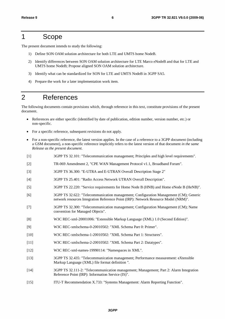
Figure 1: HNB/HNB-GW architecture with OAM interfaces
Figure 1 is the Home Node B equivalent to Figure 9 in the 3GPP specification TS 25.401 [4] and depicts both an integrated HNB on the left side and standalone HNB with a co-located Broadband Service on the right hand side.
The logical OAM is the signalling associated with the control of logical resources owned by the Management Platform but physically implemented in the HNB and notified to the HNB-GW. This contribution suggests that the messages needed in the information exchange between the Management Platform and the HNB are an integral part of TR-069 as defined by the Broadband Forum [2]. The subsequent messages needed in the information exchange between the HNB and the HNB-GW is an integral part of HNBAP as defined by 3GPP RAN3.
Implementation Specific OAM functions are heavily dependent on the implementation of the HNB, both for its hardware components and for the management of the software components. This contribution suggests that the messages needed in the information exchange are an integral part of TR-069 as defined by the Broadband Forum [2].
There are two equivalent, alternative paths for communications between the HNB and the Management Platform for OAM purposes. These are:
1. The TR-069 management path is between the HNB and the Management Platform via a secure IPSec tunnel that terminates at the Security Gateway element of the HNB-GW. Management traffic is then routed from the private side of the Security Gateway through the operator’s IP network to reach the Management Platform. The TR-069 management traffic may share the same IPSec SA as the HNB bearer and control traffic, or may optionally use a discrete IPSec SA in the same, or a different IPSec tunnel instance pending 3GPP Iuh standardisation, as per Figure 2.
2. The TR-069 management path is directly between the HNB and the Management Platform via a routed IP path that does not traverse any element through the HNB-GW, including the Security Gateway. The management path is therefore independent of the HNB-GW’s security method, geographic location and availability, as per Figure 1.
In both cases, TR-069 OAM and HNB bearer/control traffic share the same physical interface at the HNB into the broadband IP network.
3GPP
3GPP TR 32.821 V9.0.0 (2009-06) 9 Release 9
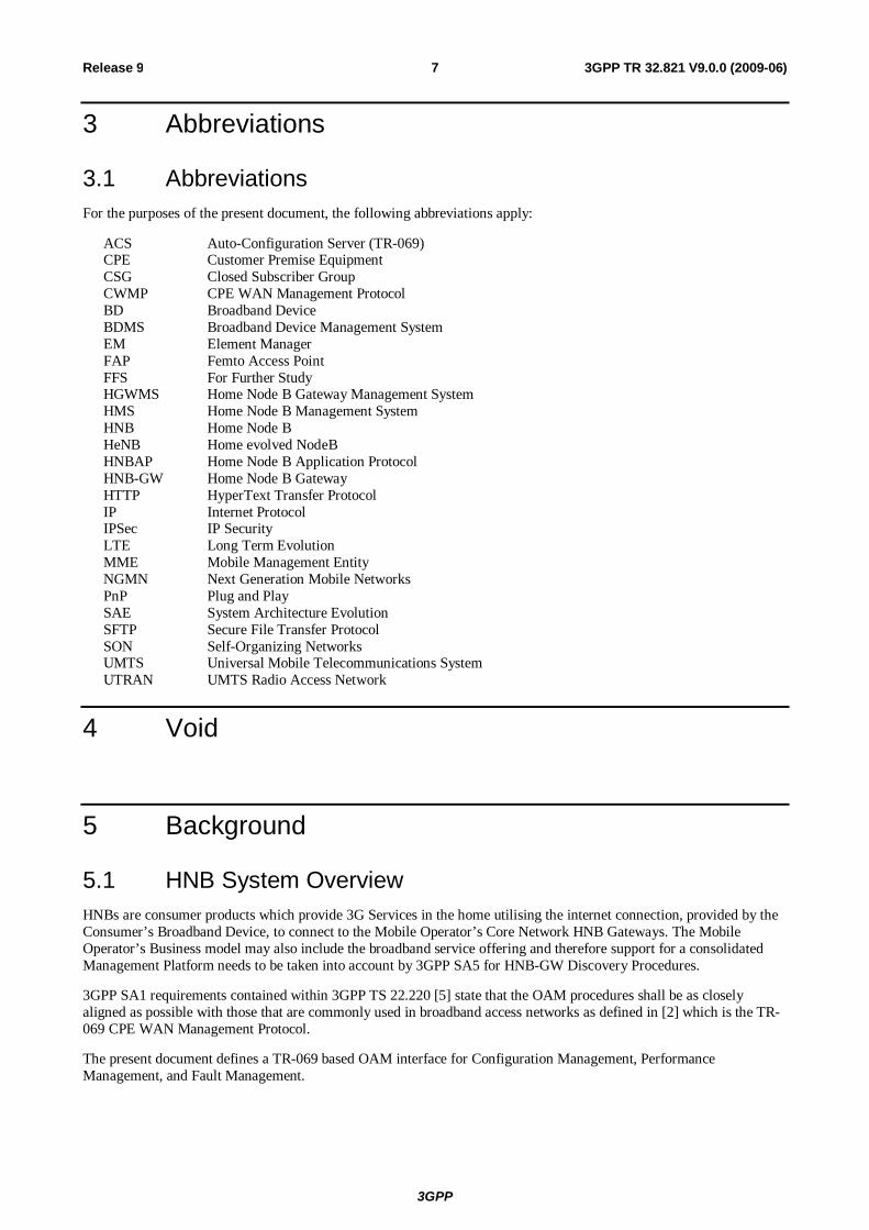
Figure 2: HNB/HNB-GW architecture with OAM interfaces via IPSEC Tunnel
The TR-069 Management connection between the Serving HMS and HNB is not persistent and therefore to establish a Management Connection requires the Serving HMS to send an HTTP Connection Request to the HNB, as shown in Figure 2.
The HTTP Connection request sent from the Serving HMS to the HNB shall follow one of the following options:
a. if the IPSEC tunnel’s end point IP-Address allocated to the HNB is uniquely allocated across all Security Gateways within the network then the HTTP Connection Request can be sent to the Security Gateway to be forwarded to the HNB
b. if the IPSEC tunnel’s end point IP-Address allocated to the HNB is not uniquely allocated across all Security Gateways within the network or is uniquely allocated but the HTTP Connection request is restricted from being sent down the IPSEC Tunnel directly due to the Security Policy then the HTTP Connection Request can be sent to the Serving HNB-GW to be sent to the HNB via HNBAP
The challenges from a deployment perspective are with FAP Initialisation and FGW Discovery which are as follows:
a. Network Operator’s with a consolidated Broadband and FAP offering may require to combine the TR-069 ACS Platforms in their network which requires secure communication to the ACS Servers prior to IPSec Tunnel establishment
b. TR-069 CPE devices are currently factory programmed with a Bootstrap ACS URL only and therefore FAP capable CPEs either require to be factory programmed with Bootstrap Security Gateway/IPSec Information or this information is supplied outside of the IPSec tunnel before tunnel establishment
The HNBAP interaction between the HNB-GW and the HNB is recognised as 3GPP RAN3 defined and is out of scope of this document.
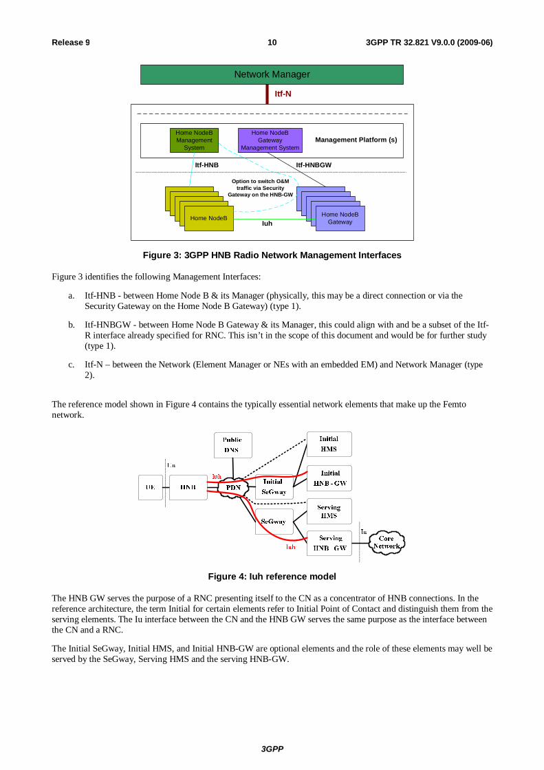
5.2 HNB System Interface and Reference Points 5.2.1 InterfacesFigure 3 shows the Management Reference Model and Interfaces for the 3GPP HNB System’s Radio Network Layer.
3GPP
3GPP TR 32.821 V9.0.0 (2009-06) 10 Release 9
Home NodeB Management
System
Home NodeB Gateway
Management System
Itf-N
Network Manager
Management Platform (s)
Home NodeBHome NodeB
Home NodeBHome NodeB
Home NodeB
Home NodeB GatewayHome NodeB
GatewayHome NodeB GatewayHome NodeB
GatewayHome NodeB Gateway
Itf-HNB Itf-HNBGW
Iuh
Option to switch O&M traffic via Security
Gateway on the HNB-GW
Figure 3: 3GPP HNB Radio Network Management Interfaces
Figure 3 identifies the following Management Interfaces:
a. Itf-HNB - between Home Node B & its Manager (physically, this may be a direct connection or via the Security Gateway on the Home Node B Gateway) (type 1).
b. Itf-HNBGW - between Home Node B Gateway & its Manager, this could align with and be a subset of the Itf-R interface already specified for RNC. This isn’t in the scope of this document and would be for further study (type 1).
c. Itf-N – between the Network (Element Manager or NEs with an embedded EM) and Network Manager (type 2).
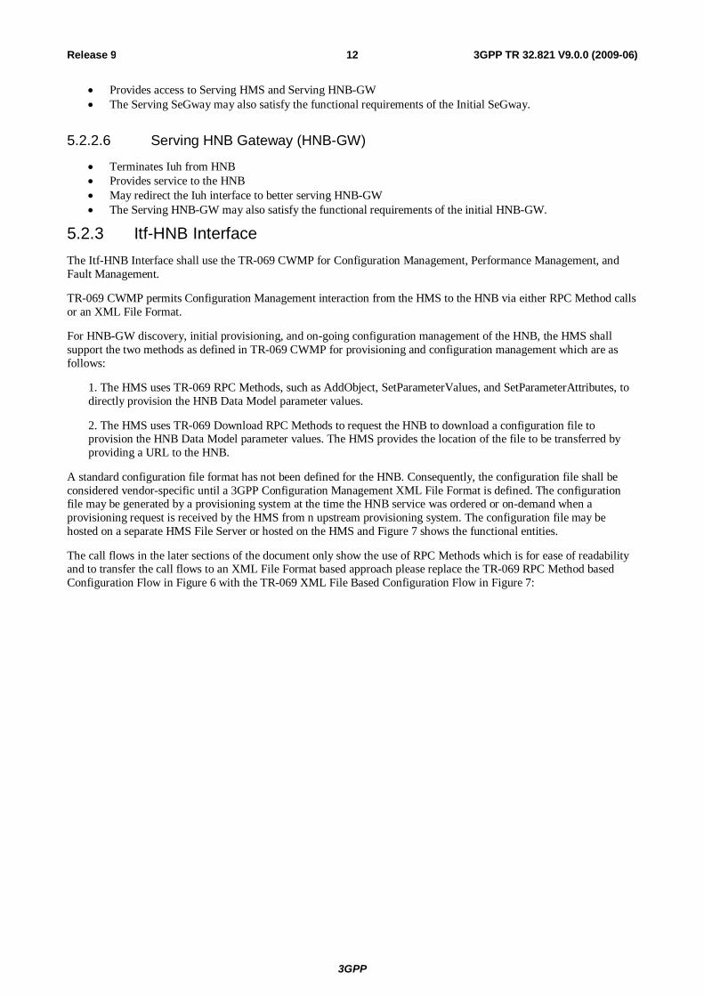
The reference model shown in Figure 4 contains the typically essential network elements that make up the Femto network.
Figure 4: Iuh reference model
The HNB GW serves the purpose of a RNC presenting itself to the CN as a concentrator of HNB connections. In the reference architecture, the term Initial for certain elements refer to Initial Point of Contact and distinguish them from the serving elements. The Iu interface between the CN and the HNB GW serves the same purpose as the interface between the CN and a RNC.
The Initial SeGway, Initial HMS, and Initial HNB-GW are optional elements and the role of these elements may well be served by the SeGway, Serving HMS and the serving HNB-GW.

3GPP
3GPP TR 32.821 V9.0.0 (2009-06) 11 Release 9
Figure 5: TR069 based provisioning
The interface to the provisioning and management elements is via the TR-069 family of standards and in Figure 5 above, TR-069 CWMP session tunnelled through IPSec (solid blue line) is the preferred option where as TR-069 CWMP session with SSL (dotted blue line) is the fall back option if IPSec tunnelling is not possible for HMS connectivity.
5.2.2 Functional elements The following functional entities serve various roles in the bootstrapping, initial provisioning, ongoing management and operation of the HNB network:
5.2.2.1 Initial HNB Management System (HMS)
Based on TR-069 CWMP Initial provisioning of HNB Determines “Tentative Location” (unverified), which can be used to find the serving HMS, SeGway, and
HNB-GW This entity is optional; if not present, the role of the Initial HMS will be fulfilled by the Serving HMS.
5.2.2.2 Initial Security Gateway (SeGway)
IPsec security gateway IKEv2 authentication of HNB Provides access to Initial HMS (optionally) and initial HNB-GW This entity is optional; if it is not included, the role of the Initial SeGway will be fulfilled by the “serving”
SeGway.
5.2.2.3 Initial HNB Gateway (HNB-GW)
Terminates Iuh from HNB Determines whether there is a need to redirect the Iuh interface to another HNB-GW This entity is optional; if it is not included, the role of the Initial HNB-GW will be fulfilled by the Serving
HNB
5.2.2.4 Serving HNB Management System (HMS)
Based on TR-069 CWMP Determines the Certified Location of the HNB (potentially based on Radio Environment Measurements
(REMs) Provides final provisioning of HNB and ongoing management functions (e.g., measurement and event
reporting) Directs HNB to Serving HNB-GW The Serving HMS may also satisfy the functional requirements of the Initial HMS.
5.2.2.5 Serving Security Gateway (SeGway)
IPsec security gateway IKEv2 authentication of HNB
3GPP
3GPP TR 32.821 V9.0.0 (2009-06) 12 Release 9
Provides access to Serving HMS and Serving HNB-GW The Serving SeGway may also satisfy the functional requirements of the Initial SeGway.
5.2.2.6 Serving HNB Gateway (HNB-GW)
Terminates Iuh from HNB Provides service to the HNB May redirect the Iuh interface to better serving HNB-GW The Serving HNB-GW may also satisfy the functional requirements of the initial HNB-GW.
5.2.3 Itf-HNB Interface The Itf-HNB Interface shall use the TR-069 CWMP for Configuration Management, Performance Management, and Fault Management.
TR-069 CWMP permits Configuration Management interaction from the HMS to the HNB via either RPC Method calls or an XML File Format.
For HNB-GW discovery, initial provisioning, and on-going configuration management of the HNB, the HMS shall support the two methods as defined in TR-069 CWMP for provisioning and configuration management which are as follows:
1. The HMS uses TR-069 RPC Methods, such as AddObject, SetParameterValues, and SetParameterAttributes, to directly provision the HNB Data Model parameter values.
2. The HMS uses TR-069 Download RPC Methods to request the HNB to download a configuration file to provision the HNB Data Model parameter values. The HMS provides the location of the file to be transferred by providing a URL to the HNB.
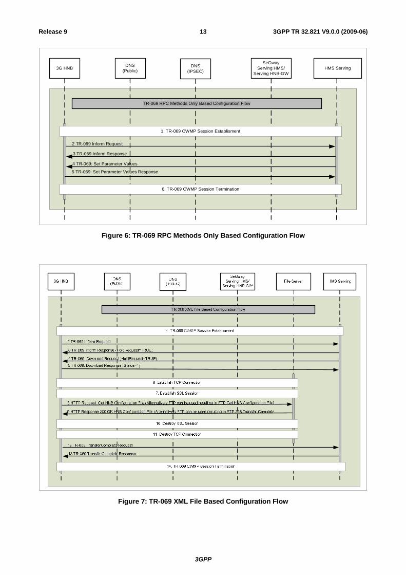
A standard configuration file format has not been defined for the HNB. Consequently, the configuration file shall be considered vendor-specific until a 3GPP Configuration Management XML File Format is defined. The configuration file may be generated by a provisioning system at the time the HNB service was ordered or on-demand when a provisioning request is received by the HMS from n upstream provisioning system. The configuration file may be hosted on a separate HMS File Server or hosted on the HMS and Figure 7 shows the functional entities.
The call flows in the later sections of the document only show the use of RPC Methods which is for ease of readability and to transfer the call flows to an XML File Format based approach please replace the TR-069 RPC Method based Configuration Flow in Figure 6 with the TR-069 XML File Based Configuration Flow in Figure 7:
3GPP
3GPP TR 32.821 V9.0.0 (2009-06) 13 Release 9
DNS(IPSEC)
DNS(Public)
SeGwayServing HMS/
Serving HNB-GWHMS Serving3G HNB
3 TR-069 Inform Response
4 TR-069: Set Parameter Values
5 TR-069: Set Parameter Values Response
2 TR-069 Inform Request
1. TR-069 CWMP Session Establisment
6. TR-069 CWMP Session Termination
TR-069 RPC Methods Only Based Configuration Flow
Figure 6: TR-069 RPC Methods Only Based Configuration Flow
Figure 7: TR-069 XML File Based Configuration Flow
3GPP
3GPP TR 32.821 V9.0.0 (2009-06) 14 Release 9
6 Requirements
6.1 OAM Business level requirements of Home Node B
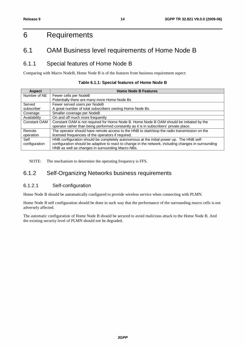
6.1.1 Special features of Home Node B Comparing with Macro NodeB, Home Node B is of the features from business requirement aspect:
Table 6.1.1: Special features of Home Node B
Aspect Home Node B Features Number of NE Fewer cells per NodeB
Potentially there are many more Home Node Bs Served subscriber
Fewer served users per NodeB A great number of total subscribers owning Home Node Bs
Coverage Smaller coverage per NodeB Availability On and off much more frequently Constant OAM Constant OAM is not required for Home Node B. Home Node B OAM should be initiated by the
operator rather than being performed constantly as it is in subscribers’ private place. Remote operation
The operator should have remote access to the HNB to start/stop the radio transmission on the licensed frequencies of the operators if required.
Self configuration
HNB configuration should be completely autonomous at the initial power up. The HNB self-configuration should be adaptive to react to change in the network, including changes in surrounding HNB as well as changes in surrounding Macro NBs.
NOTE: The mechanism to determine the operating frequency is FFS.
6.1.2 Self-Organizing Networks business requirements
6.1.2.1 Self-configuration
Home Node B should be automatically configured to provide wireless service when connecting with PLMN.
Home Node B self configuration should be done in such way that the performance of the surrounding macro cells is not adversely affected.
The automatic configuration of Home Node B should be secured to avoid malicious attack to the Home Node B. And the existing security level of PLMN should not be degraded.
3GPP
3GPP TR 32.821 V9.0.0 (2009-06) 15 Release 9
6.1.3 Standards Alignment The OAM&P for the HNB shall be based on the following standards:
- Broadband Forum TR-069 CPE WAN Management Protocol Amendment 2 TR-098 and TR-106 Data Models
- 3GPP Organization TS-32.000 Series – Generic OAM Specifications and XML File Formats TS-25.400 Series – OAM Architecture for RNS and HNBAP Protocol TS-33.000 Series - Security aspects.
- ITU Organization X.733 – Systems Management: Alarm Reporting Function X.736 - Systems Management: Security Alarm Reporting Function
- W3C Organization REC-xml-200001006 – Extensible Markup Language (XML) 1.0 (Second Edition) REC-xmlschema-0-20010502 - XML Schema Part 0: Primer REC-xmlschema-1-20010502 - XML Schema Part 1: Structures REC-xmlschema-2-20010502 - XML Schema Part 2: Datatypes REC-xml-names-19990114 - Namespaces in XML
The OAM&P for the HNB-GW shall be based on the following standards:
- 3GPP Organization TS-32.000 Series – Generic OAM Specifications and XML File Formats TS-25.400 Series – OAM Architecture for RNS and HNBAP Protocol
3GPP
3GPP TR 32.821 V9.0.0 (2009-06) 16 Release 9
6.2 OAM specification level requirements of Home Node B
6.2.1 HNB OAM Specification Level Requirement (Interface Type 1)
6.2.1.1 Self-Configuration
The Home Node B shall support Self-Configuration so that it can be automatically configured to provide mobile service on initial power-up and connection to the mobile network.
For each Home Node B, the detailed requirements for Self-Configuration are as follows:
1. The Home Node B should be able to establish a secured link with the “mobile OAM network” according to network operator security policy. The way how security information is provided to the Home Node B is out of scope of this document.
2. Both HMS and Home Node B should be able to initiate software download and activation of Home Node B.
3. HMS should be able to initiate provisioning of transport resources for Home Node B in order to establish signalling links with PLMN (subject to definite agreement on architecture).
4. HMS should provide Home Node B with radio network specific information to allow Home Node B to automatically configure to an operable state. In order for HMS to provide correct radio resources to Home Node B, HMS should be provided radio parameters of the existing radio environment where the Home Node B is, such as radio parameters of other existing cells.
Editor’s note: If the Home Node B has enough information, Home Node B should not have to contact with HMS for self-configuration.
6.2.1.2 Configuration management
6.2.1.2.1 General requirements
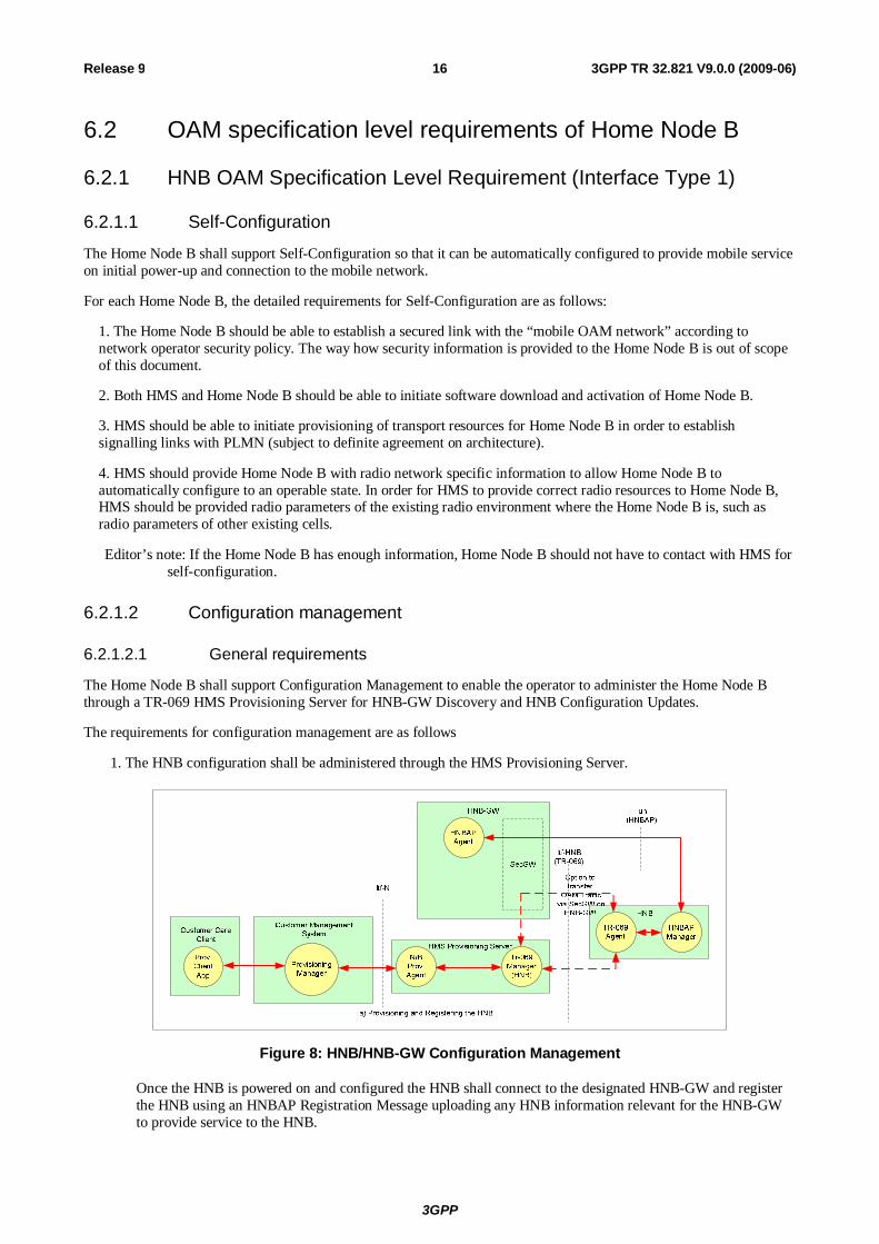
The Home Node B shall support Configuration Management to enable the operator to administer the Home Node B through a TR-069 HMS Provisioning Server for HNB-GW Discovery and HNB Configuration Updates.
The requirements for configuration management are as follows
1. The HNB configuration shall be administered through the HMS Provisioning Server.
Figure 8: HNB/HNB-GW Configuration Management
Once the HNB is powered on and configured the HNB shall connect to the designated HNB-GW and register the HNB using an HNBAP Registration Message uploading any HNB information relevant for the HNB-GW to provide service to the HNB.
3GPP
3GPP TR 32.821 V9.0.0 (2009-06) 17 Release 9
HNB OAM Traffic can be transferred through the HNB-GW but the OAM traffic exchanged over this signalling link is completely transparent to the Security Gateway on the HNB-GW
2. The HNB Data Model administered by the HMS Provisioning Server shall be based on the following:
a. Broadband Forum TR-106 Amendment 1 Data Model
b. Femto Forum HNB Service data Model
3. The Customer Management System shall have the capability to bulk provision HNBs on the HMS Provisioning Server by downloading an XML File from the Customer Management System through the North-Bound Interface of the HMS Provisioning Server
4. Both the standalone HNB and Broadband Device with integrated HNB have the option to communicate with the HMS Provisioning Server either directly outside the IPSec Tunnel or indirectly through the IPSec Tunnel which would utilise the same physical bearer used by the luh interface.
5. Network Operator’s with a consolidated Broadband and HNB offering shall be able or have the option to combine the TR-069 HMS Platforms in their network which requires secure communication to the HMS Servers prior to IPSEC Tunnel establishment.
6. TR-069 CPE devices are currently factory programmed with a Bootstrap HMS URL only and therefore HNB capable CPEs either require to be factory programmed with Bootstrap Security Gateway/IPSec Information or this information is supplied outside of the IPSEC tunnel before tunnel establishment
6.2.1.2.2 Configuration data validation online
FFS
6.2.1.2.3 Configuration data
For each Home Node B, the following configuration data should be managed by the corresponding HMS:
1. Operator’s pre-set policy regarding SON functionality
2. Transport parameters
3. Radio parameters
Editor's Note: Concrete data are FFS
6.2.1.2.4 Remote control
1. HMS shall be able to reboot Home Node B.
2. HMS shall be able to take Home Node B out of service.
3. The HMS shall be able to modify/change the Home NB configuration.
6.2.1.2.5 HNB-GW Discovery method
The HNB on connection to the Mobile Operator’s Network through the Internet needs to establish a connection to a HNB-GW in-order to provide 3G Services to the consumer. The Serving HMS in the network provides the HNB with the Serving HNB-GW information as well as the Service Information required to establish and provide 3G Services.
The HNB is factory programmed with default TR-069 based Management Platform information (HMS URL/IP-Address) and optionally with default IPSec/SEC-GW information to allow the establishment of a Secure Tunnel if this is a pre-requisite to gain access to the Management Platform for Configuration information.
HNB-GW Discovery Procedure below assumes that the Factory Set HMS on the HNB isn’t the same as the HMS operationally serving the HNB in the network:
3GPP
3GPP TR 32.821 V9.0.0 (2009-06) 18 Release 9
DNS(IPSEC)
SeGwayInitial HMS
HMSInitial
DNS(Public)
6 TR-069 Inform Response
7 TR-069: Set Parameter Values (List of {Serving HMSs, [List of Serving SeGways]}, [List of {Serving HNB-GWs, RNC-IDs, Serving HNB-GW Provisioning Data, Serving SeGways}])
8 TR-069: Set Parameter Values Response
5 TR-069 Inform Request (HNB is initialised, [Last Registered HNB-GW], [NetworkListen Results], [GPS Fix])
SeGwayServing HMS/
Serving HNB-GW
HMS Serving3G HNB
3.4 DNS Request (Initial HMS)
3.5 DNS Response(Resolved Ips)
1 LAN Connection to Internet for 3G HNB Established
3.3 Establish IPSEC Tunnel
12.1 Destroy IPSEC Tunnel
3.1 DNS Request (Initial SeGway)
3.2 DNS Response(Resolved Ips)
2.1 DNS Request (Initial HMS)
2.2 DNS Response(Resolved Ips)
4. TR-069 CWMP Session Establisment
9. TR-069 CWMP Session Termination
12.5 DNS Request (Serving HMS)
12.6 DNS Response(Resolved Ips)
12.4 Establish IPSEC Tunnel
12.2 DNS Request (Serving SeGway)
12.3 DNS Response(Resolved Ips)
10.1 DNS Request (Serving HMS)
10..2 DNS Response(Resolved Ips)
15 TR-069 Inform Response
16 TR-069: Set Parameter Values (List of {HNBGWs, RNC-IDs, Serving HNB-GW Provisioning Data, SeGways}, Certified HNB Location, HNB Provisioning Data, Parameter Authentication Code)
17 TR-069: Set Parameter Values Response
14 TR-069 Inform Request (HNB is initialised, NetworkListen Results, [GPS Fix], [Last Registered HNB-GW], [Alarms])
19 Destroy IPSEC Tunnel
13. TR-069 CWMP Session Establisment
18. TR-069 CWMP Session Termination
11.1 DNS Request (Serving HMS)
11..2 DNS Response(Resolved Ips)
{} denotes a Parameter Structure and [] denotes an optional Parameter.
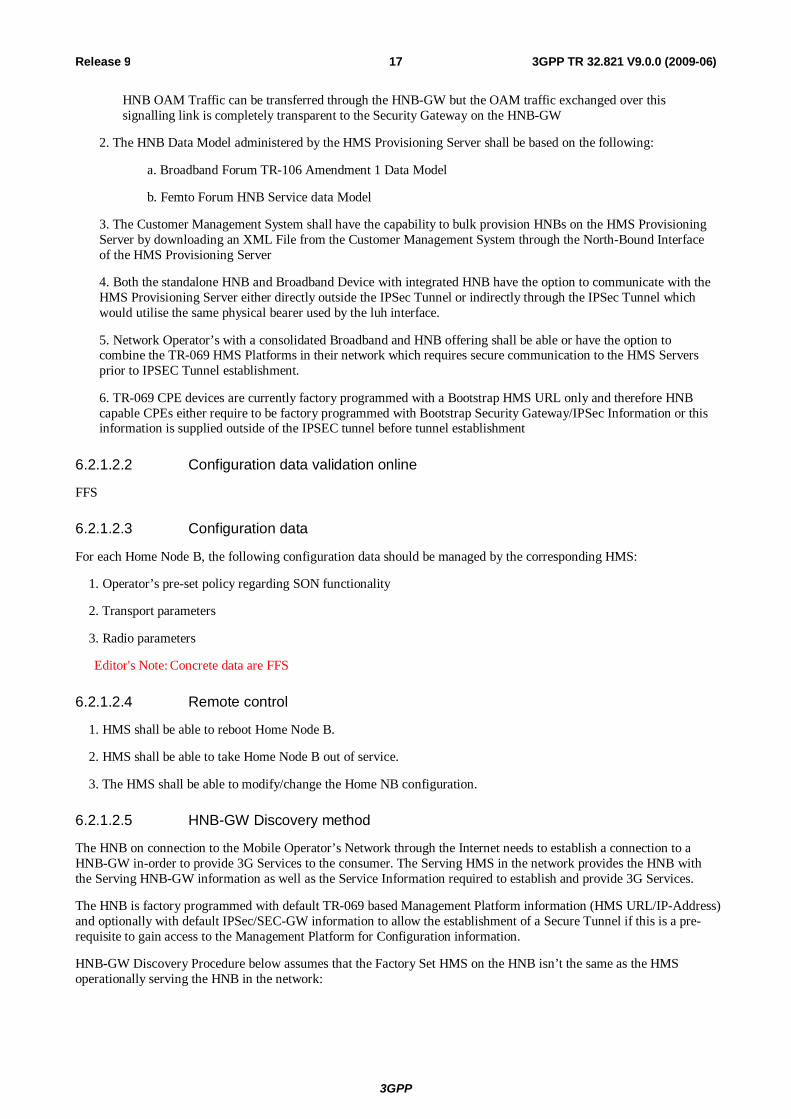
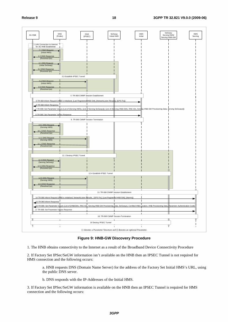
Figure 9: HNB-GW Discovery Procedure
1. The HNB obtains connectivity to the Internet as a result of the Broadband Device Connectivity Procedure
2. If Factory Set IPSec/SeGW information isn’t available on the HNB then an IPSEC Tunnel is not required for HMS connection and the following occurs:
a. HNB requests DNS (Domain Name Server) for the address of the Factory Set Initial HMS’s URL, using the public DNS server.
b. DNS responds with the IP-Addresses of the Initial HMS.
3. If Factory Set IPSec/SeGW information is available on the HNB then an IPSEC Tunnel is required for HMS connection and the following occurs:
3GPP
3GPP TR 32.821 V9.0.0 (2009-06) 19 Release 9
a. HNB requests DNS (Domain Name Server) for the address of the Factory Set Initial SeGway’s URL, using the public DNS server.
b. DNS responds with the IP-Addresses of the Initial Segway.
c. Secure IPSEC Tunnel is established between the HNB and SeGway.
d. HNB requests DNS (Domain Name Server) for the address of the Factory Set Initial HMS URL, using the DNS server IP address provided along with IPSec tunnel.
e. DNS responses with the IP-Addresses of the Initial HMS.
4. The TR-069 CWMP Session is established towards the Initial HMS. An SSL Connection is established between HNB and HMS when either the Secure IPSEC Tunnel hasn’t been established (Step 3.3) or when the TR-069 CWMP session is to be established outside the IPSec tunnel as per the Security Policy. If the TR-069 CWMP session is to be established within the IPSEC Tunnel as per the Security Policy then the SSL session shall not be established between the HNB and HMS.
5. The HNB sends an Inform Request containing registration information such as HNB Identifier to the Initial HMS along with optional location information (Network Listen Results and GPS Fix).
6. HMS decides whether the HNB is authorized or not. If the connection is permitted, HMS sends an Inform response which permits both entities to establish communication.
7. The Initial HMS then obtains the Serving HMS Information (e.g. URL/IP-Address) and sets the value on the HNB using the Set Parameter Values Message. The HMS can optionally provide Serving IPSec/SeGW information at the same time which is used to establish a new secure tunnel before subsequent HMS interaction. In addition the Initial HMS can supply a list of Serving HNB-GWs accompanied with associated HNB-GW information)
8. The HNB acknowledges the update of information from the HMS by sending a Set Parameter Values Response.
9. The HNB releases the TR-069 CWMP Session and if the SSL connection was also established as part of Step 4 above then this shall also be released.
10. If both the HMS Serving IPSec/SeGW information and the Factory Set IPSec/SeGW information aren’t available on the HNB then an IPSEC Tunnel is not required for HMS connection and the following occurs:
a. HNB requests DNS (Domain Name Server) for the address of the Serving HMS, using the public DNS server.
b. DNS responds with the IP-Addresses of the Serving HMS.
11. If the HMS Serving IPSec/SeGW information isn’t available on the HNB and the Factory Set IPSec/SeGW information is available then an IPSEC Tunnel is required for HMS connection and the following occurs:
a. HNB requests DNS (Domain Name Server) for the address of the Serving HMS, using the DNS server IP address provided along with IPSec tunnel.
b. DNS responds with the IP-Addresses of the Serving HMS.
12. If HMS Serving IPSec/SeGW information is available on the HNB and required for HMS connection then an IPSEC Tunnel is required for HMS connection and the following occurs:
a. if a Secure Tunnel is already established as part of Step 3.3 above then the Secure Tunnel is released between the HNB and SeGway otherwise the Secure Tunnel remains established.
b. HNB requests DNS (Domain Name Server) for the address of the Serving SeGway, using the public DNS server.
c. DNS responds with the IP-Addresses of the Serving SeGway.
d. Secure IPSEC Tunnel is established between the HNB and SeGway.
e. HNB requests DNS (Domain Name Server) for the address of the Serving HMS, using the DNS server IP address provided along with IPSec tunnel.
f. DNS responses with the IP-Addresses of the Serving HMS.

3GPP
3GPP TR 32.821 V9.0.0 (2009-06) 20 Release 9
13. The TR-069 CWMP Session is established towards the Serving HMS. An SSL Connection is established between HNB and HMS when either the Secure IPSEC Tunnel hasn’t been established (Step 12.3) or when the TR-069 CWMP session is to be established outside the IPSec tunnel as per the Security Policy. If the TR-069 CWMP session is to be established within the IPSEC Tunnel as per the Security Policy then the SSL session shall not be established between the HNB and HMS
14. The HNB sends an Inform Request containing registration information such as HNB Identifier to the operationally Serving HMS, the Location information (Network Listen Results), and optionally the location information (GPS Fix), Alarms, Last Registered HNB-GW.
15. HMS decides whether the HNB is authorized or not. If the connection is permitted, HMS sends an Inform response which permits both entities to establish communication.
16. The HMS then obtains the information for 3G Service as well as the Serving HNB-GW and sets the value on the HNB using the Set Parameter Values Message. The HMS supplies along with the HNB-GW Identifier the Serving IPSec/SeGway information, the HNB-GW Provisioning Data, the HNB provisioning Data, and a ParameterAuthenticationCode. The SeGway information assigned to the HNB-GW overrides the SeGway information assigned previously to the HMS and shall be used to ensure a secure tunnel is established before subsequent HMS and HNB-GW interaction.
17. The HNB acknowledges the update of information from the HMS by sending a Set Parameter Values Response.
18. The HNB releases the TR-069 CWMP Session and if the SSL connection was also established as part of Step 13 above then this shall also be released.
19. If new Serving IPSec/SeGW information is available for the HNB-GW and a Secure Tunnel is already established then the Secure Tunnel is released between the HNB and SeGW otherwise the Secure Tunnel remains established.
As mentioned above, this document introduces a TR-069 mechanism to support the discovery of the HNB-GW and supply of the Service Information from the Home Management System to the HNB to establish 3G Services.
6.2.1.2.6 HNB Registration method
Once the HNB has discovered the Serving HNB-GW and Serving IPSec/SeGW from the HMS it establishes a connection to a HNB-GW in-order to provide 3G Services to the consumer.
The HNB-GW Information provided to the HNB can be a dedicated HNB-GW for the HNB or through various techniques such as load-balancing and service availability the HNB-GW address can be used to register the HNB on one of many HNB-GWs within a pre-defined pool of HNB-GWs.
HNB Registration Procedure below:
3GPP
3GPP TR 32.821 V9.0.0 (2009-06) 21 Release 9
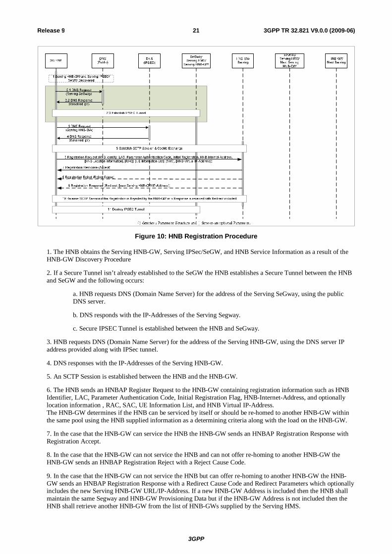
Figure 10: HNB Registration Procedure
1. The HNB obtains the Serving HNB-GW, Serving IPSec/SeGW, and HNB Service Information as a result of the HNB-GW Discovery Procedure
2. If a Secure Tunnel isn’t already established to the SeGW the HNB establishes a Secure Tunnel between the HNB and SeGW and the following occurs:
a. HNB requests DNS (Domain Name Server) for the address of the Serving SeGway, using the public DNS server.
b. DNS responds with the IP-Addresses of the Serving Segway.
c. Secure IPSEC Tunnel is established between the HNB and SeGway.
3. HNB requests DNS (Domain Name Server) for the address of the Serving HNB-GW, using the DNS server IP address provided along with IPSec tunnel.
4. DNS responses with the IP-Addresses of the Serving HNB-GW.
5. An SCTP Session is established between the HNB and the HNB-GW.
6. The HNB sends an HNBAP Register Request to the HNB-GW containing registration information such as HNB Identifier, LAC, Parameter Authentication Code, Initial Registration Flag, HNB-Internet-Address, and optionally location information , RAC, SAC, UE Information List, and HNB Virtual IP-Address. The HNB-GW determines if the HNB can be serviced by itself or should be re-homed to another HNB-GW within the same pool using the HNB supplied information as a determining criteria along with the load on the HNB-GW.
7. In the case that the HNB-GW can service the HNB the HNB-GW sends an HNBAP Registration Response with Registration Accept.
8. In the case that the HNB-GW can not service the HNB and can not offer re-homing to another HNB-GW the HNB-GW sends an HNBAP Registration Reject with a Reject Cause Code.
9. In the case that the HNB-GW can not service the HNB but can offer re-homing to another HNB-GW the HNB-GW sends an HNBAP Registration Response with a Redirect Cause Code and Redirect Parameters which optionally includes the new Serving HNB-GW URL/IP-Address. If a new HNB-GW Address is included then the HNB shall maintain the same Segway and HNB-GW Provisioning Data but if the HNB-GW Address is not included then the HNB shall retrieve another HNB-GW from the list of HNB-GWs supplied by the Serving HMS.
3GPP
3GPP TR 32.821 V9.0.0 (2009-06) 22 Release 9
10. In the event of a Registration Reject or Registration response with redirect the SCTP connection is released.
11. In the event of either a Registration Reject or a Registration Response with a Redirect Cause Code with no new HNB-GW Address provided then the existing Secure Tunnel is also released.
As mentioned above, this document introduces the supply of the Service Information to the HNB-GW from the HNB.
6.2.1.2.7 HNB Configuration Update method
Once the HNB has registered on the Serving HNB-GW the 3G Services will be provided to the consumer and will only be affected if the Mobile Operator updates the configuration of the HNB on the HMS which impacts the HNB operational state of the 3G Services provided.
To update the HNB of service changes the HMS establishes a connection with the HNB using TR-069 and then the HNB subsequently passes up any HNB-GW relevant changes via HNBAP using an additional HNBAP Message HNB Configuration Update. This is equivalent functionality to S1-AP: ENB Configuration Update Procedure contained within the 3GPP TS 36.300 Title “E-UTRA and E-UTRAN Overall Description Stage 2” document [3].
HNB Configuration Update Procedure below:
DNS(IPSEC)
DNS(Public)
HMSServing
HNB-GW Serving3G HNB
1 3G HNB Registered on the Serving HNB-GW
2.1 DNS Request (HNB Connection Request URL)
2.2 DNS Response(Resolved Ips)
7 TR-069 Inform Response
8 TR-069: Set Parameter Values ([List of {HNBGWs, RNC-IDs, Serving HNB-GWs Provisioning Data, SeGways}], [HNB Provisioning Data], [Parameter Authentication Code])
9 TR-069: Set Parameter Values Response
6 TR-069 Inform Request (ACS Requested Connection, [Alarms])
5. TR-069 CWMP Session Establisment
10. TR-069 CWMP Session Termination
3.3 HTTP Connection Response (200 OK)
3.2 HTTP Connection Request (HTTP Digest Access Authentication)
12 Registration Response (Accept)
11 Registration Request (HNB Identity, LAC, Parameter Authentication Code, Configuration Update Flag, HNB-Internet-Address, [HNB Location Information], [RAC], [UE Information List], [SAC], [HNB-Virtual IP-Address])
16 Destroy IPSEC Tunnel
13 Registration Reject (Reject Cause)
14 Registration Response (Redirect, [new Serving HNB-GW IP-Address])
SeGwayServing HMS/
Serving HNB-GW
15 Release SCTP Session if the Registration is Rejected by the HNB-GW or a Response is received with Redirect included
{} denotes a Parameter Structure and [] denotes an optional Parameter.
4.5 HTTP Connection Response (200 OK)
3.4 Close TCP Session
3.1 Open TCP Session
4.1 Open TCP Session
4.2 HTTP Connection Request ([HTTP Digest Access Authentication])
4.4 Connect Response (Connect Cause=Accept)
4.3 Connect Request ()
4.6 Close TCP Session
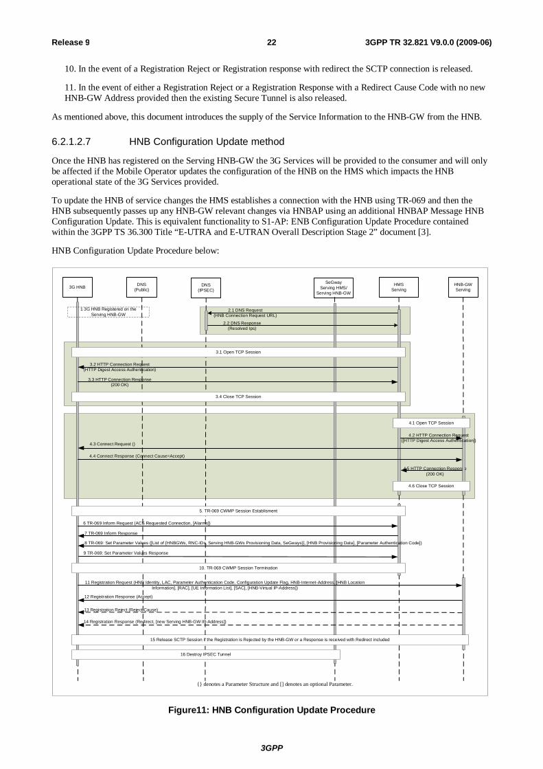
Figure11: HNB Configuration Update Procedure
3GPP
3GPP TR 32.821 V9.0.0 (2009-06) 23 Release 9
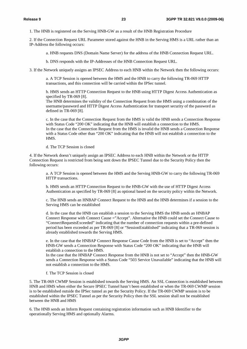
1. The HNB is registered on the Serving HNB-GW as a result of the HNB Registration Procedure
2. If the Connection Request URL Parameter stored against the HNB in the Serving HMS is a URL rather than an IP-Address the following occurs:
a. HNB requests DNS (Domain Name Server) for the address of the HNB Connection Request URL.
b. DNS responds with the IP-Addresses of the HNB Connection Request URL.
3. If the Network uniquely assigns an IPSEC Address to each HNB within the Network then the following occurs:
a. A TCP Session is opened between the HMS and the HNB to carry the following TR-069 HTTP transactions, and this connection will be carried within the IPSec tunnel.
b. HMS sends an HTTP Connection Request to the HNB using HTTP Digest Access Authentication as specified by TR-069 [8]. The HNB determines the validity of the Connection Request from the HMS using a combination of the username/password and HTTP Digest Access Authentication for transport security of the password as defined in TR-069 [8].
c. In the case that the Connection Request from the HMS is valid the HNB sends a Connection Response with Status Code “200 OK” indicating that the HNB will establish a connection to the HMS. In the case that the Connection Request from the HMS is invalid the HNB sends a Connection Response with a Status Code other than “200 OK” indicating that the HNB will not establish a connection to the HMS.
d. The TCP Session is closed
4. If the Network doesn’t uniquely assign an IPSEC Address to each HNB within the Network or the HTTP Connection Request is restricted from being sent down the IPSEC Tunnel due to the Security Policy then the following occurs:
a. A TCP Session is opened between the HMS and the Serving HNB-GW to carry the following TR-069 HTTP transactions.
b. HMS sends an HTTP Connection Request to the HNB-GW with the use of HTTP Digest Access Authentication as specified by TR-069 [8] as optional based on the security policy within the Network.
c. The HNB sends an HNBAP Connect Request to the HNB and the HNB determines if a session to the Serving HMS can be established
d. In the case that the HNB can establish a session to the Serving HMS the HNB sends an HNBAP Connect Response with Connect Cause =”Accept”. Alternative the HNB could set the Connect Cause to “ConnectRequestsExceeded” indicating that the number of connection requests within a pre-defined period has been exceeded as per TR-069 [8] or “SessionEstablished” indicating that a TR-069 session is already established towards the Serving HMS.
e. In the case that the HNBAP Connect Response Cause Code from the HNB is set to “Accept” then the HNB-GW sends a Connection Response with Status Code “200 OK” indicating that the HNB will establish a connection to the HMS. In the case that the HNBAP Connect Response from the HNB is not set to “Accept” then the HNB-GW sends a Connection Response with a Status Code “503 Service Unavailable” indicating that the HNB will not establish a connection to the HMS.
f. The TCP Session is closed
5. The TR-069 CWMP Session is established towards the Serving HMS. An SSL Connection is established between HNB and HMS when either the Secure IPSEC Tunnel hasn’t been established or when the TR-069 CWMP session is to be established outside the IPSec tunnel as per the Security Policy. If the TR-069 CWMP session is to be established within the IPSEC Tunnel as per the Security Policy then the SSL session shall not be established between the HNB and HMS
6. The HNB sends an Inform Request containing registration information such as HNB Identifier to the operationally Serving HMS and optionally Alarms.
3GPP
3GPP TR 32.821 V9.0.0 (2009-06) 24 Release 9
7. HMS decides whether the HNB is authorized or not. If the connection is permitted, HMS sends an Inform response which permits both entities to establish communication.
8. The HMS then obtains the updated information for 3G Service as well as the Serving HNB-GW and sets the value on the HNB using the Set Parameter Values Message. The HMS may supply a combination of the following HNB-GW Identifier the Serving IPSec/SeGway information, the HNB-GW Provisioning Data, the HNB provisioning Data, and a ParameterAuthenticationCode. The SeGway information assigned to the HNB-GW overrides the SeGway information assigned previously to the HMS and shall be used to ensure a secure tunnel is established before subsequent HMS and HNB-GW interaction.
9. The HNB acknowledges the update of information from the HMS by sending a Set Parameter Values Response.
10. The HNB releases the TR-069 CWMP Session and if the SSL connection was also established as part of Step 8 above then this shall also be released.
11. The HNB sends an HNBAP Register Request to the HNB-GW containing registration information such as HNB Identifier, LAC, Parameter Authentication Code, Configuration Update Flag, HNB-Internet-Address, and optionally location information , RAC, SAC, UE Information List, and HNB Virtual IP-Address. The HNB-GW determines if the HNB can be serviced by itself or should be re-homed to another HNB-GW within the same pool using the HNB supplied information as a determining criteria along with the load on the HNB-GW.
12. In the case that the HNB-GW can continue to service the HNB the HNB-GW sends an HNBAP Registration Response with Registration Accept.
13. In the case that the HNB-GW can not continue to service the HNB and can not offer re-homing to another HNB-GW the HNB-GW sends an HNBAP Registration Reject with a Reject Cause Code.
14. In the case that the HNB-GW can not continue to service the HNB but can offer re-homing to another HNB-GW the HNB-GW sends an HNBAP Registration Response with a Redirect Cause Code and Redirect Parameters which optionally includes the new Serving HNB-GW URL/IP-Address. If a new HNB-GW Address is included then the HNB shall maintain the same Segway and HNB-GW Provisioning Data but if the HNB-GW Address is not included then the HNB shall retrieve another HNB-GW from the list of HNB-GWs supplied by the Serving HMS.
15. In the event of a Registration Reject or Registration response with redirect the SCTP connection is released.
16. In the event of either a Registration Reject or a Registration Response with a Redirect Cause Code with no new HNB-GW Address provided then the existing Secure Tunnel is also released.
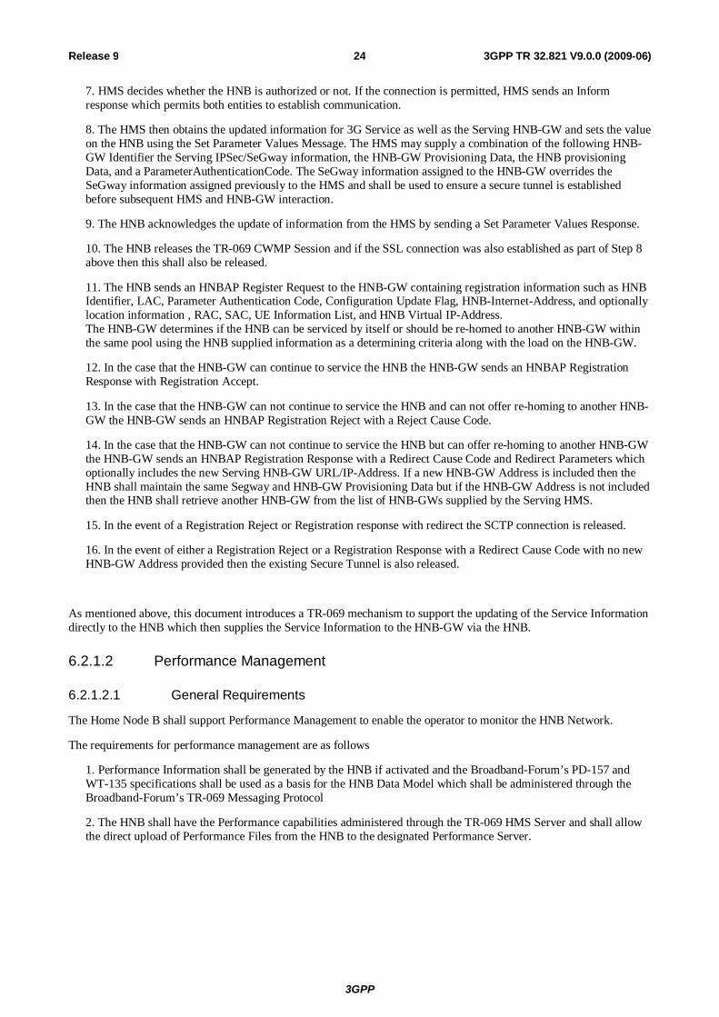
As mentioned above, this document introduces a TR-069 mechanism to support the updating of the Service Information directly to the HNB which then supplies the Service Information to the HNB-GW via the HNB.
6.2.1.2 Performance Management
6.2.1.2.1 General Requirements
The Home Node B shall support Performance Management to enable the operator to monitor the HNB Network.
The requirements for performance management are as follows
1. Performance Information shall be generated by the HNB if activated and the Broadband-Forum’s PD-157 and WT-135 specifications shall be used as a basis for the HNB Data Model which shall be administered through the Broadband-Forum’s TR-069 Messaging Protocol
2. The HNB shall have the Performance capabilities administered through the TR-069 HMS Server and shall allow the direct upload of Performance Files from the HNB to the designated Performance Server.
3GPP
3GPP TR 32.821 V9.0.0 (2009-06) 25 Release 9
Tr-069 Manager
(HNB)
Itf-HNB(TR-069)
Perform. Agent
TR-069 Agent
Perform. Manager
(HNB-GW)
Perform. Manager
(ACS +HNB)
N/B Prov. Agent
HMS Provisioning Server
HNB-GW
HNB
Perform. Agent
HMS Provisioning Server
Performance ServerHNB-GW
HNB
Performance File (HTTPS PUT or sFTP)
PerformanceManager
Database and data Mining
Tools
Perform.ClientSever
PerfomClientApp
User’s PC
Itf-N
Perform. Agent
Perform. Manager
Network Manager
Element Management System
a) Performance Management Provisioning on the HNB
b) Performance File Upload from the HNB to the Performance Server
Option to transfer
OAM Traffic via SecGW on
HNB-GW
Itf-HNB(XML File Format)
SecGWOption to transfer
OAM Traffic via SecGW on
HNB-GW
SecGW
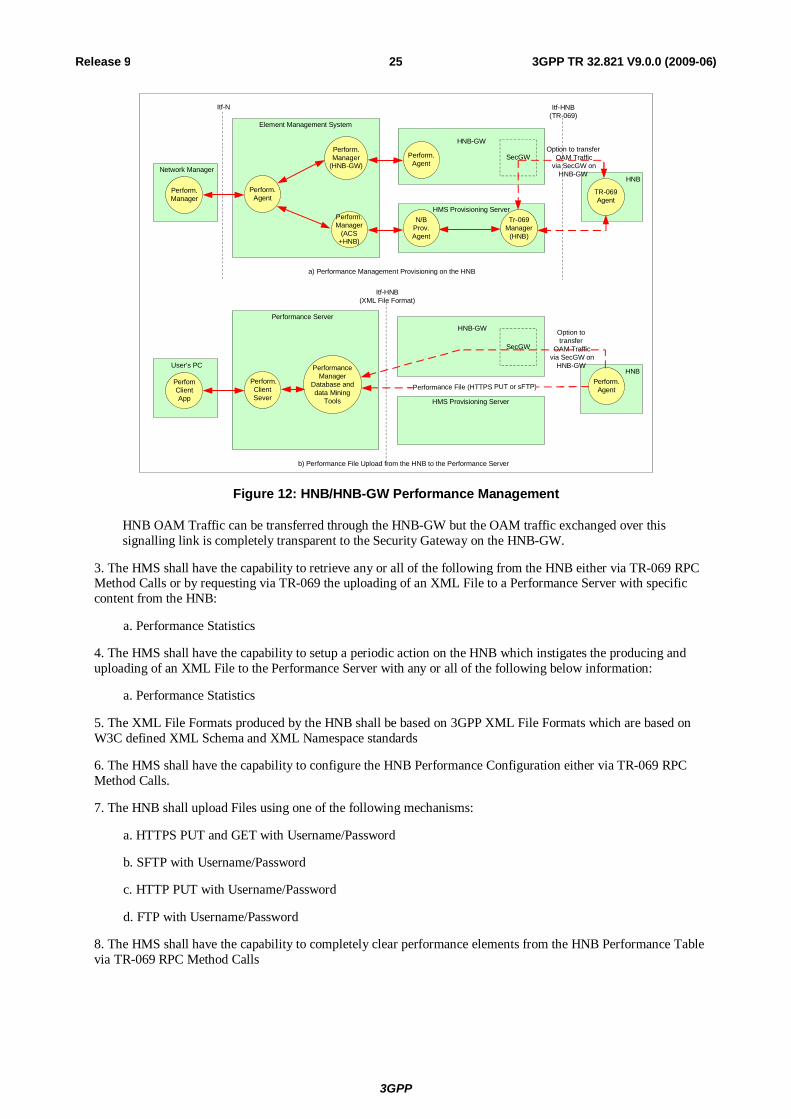
Figure 12: HNB/HNB-GW Performance Management
HNB OAM Traffic can be transferred through the HNB-GW but the OAM traffic exchanged over this signalling link is completely transparent to the Security Gateway on the HNB-GW.
3. The HMS shall have the capability to retrieve any or all of the following from the HNB either via TR-069 RPC Method Calls or by requesting via TR-069 the uploading of an XML File to a Performance Server with specific content from the HNB:
a. Performance Statistics
4. The HMS shall have the capability to setup a periodic action on the HNB which instigates the producing and uploading of an XML File to the Performance Server with any or all of the following below information:
a. Performance Statistics
5. The XML File Formats produced by the HNB shall be based on 3GPP XML File Formats which are based on W3C defined XML Schema and XML Namespace standards
6. The HMS shall have the capability to configure the HNB Performance Configuration either via TR-069 RPC Method Calls.
7. The HNB shall upload Files using one of the following mechanisms:
a. HTTPS PUT and GET with Username/Password
b. SFTP with Username/Password
c. HTTP PUT with Username/Password
d. FTP with Username/Password
8. The HMS shall have the capability to completely clear performance elements from the HNB Performance Table via TR-069 RPC Method Calls

3GPP
3GPP TR 32.821 V9.0.0 (2009-06) 26 Release 9
6.2.1.2.2 Performance Management method
The Home Node B should support Performance Management so that the operator can evaluate the performance of a mobile network with Home Node Bs. Since the number of Home Node Bs in a mobile network can be very large, Home Node B sends performance data only on demand of HMS in order to avoid congestion of the HMS by performance data transmission.
For each Home Node B, the detailed requirements for performance data passive collection are as follows:
1. Whether there is OAM connection or not, the Home Node B always generates measurement data due to its policy.
2. The Operator’s Home Node B measurement policy should be set in the HMS.
3. The Home Node B should report measurement data on demand of HMS.
Editor's Note: “on demand of HMS” doesn’t mean Home Node B has permanent connection with HMS.
6.2.1.2.3 Performance Data (KPI & counter)
For each Home Node B, HMS shall be able to collect performance data to enable to evaluate Home Node B performance.
Editor's Note: Concrete KPIs & counters are FFS
6.2.1.3 Fault Management
6.2.1.3.1 General Requirements
The Home Node B shall support Fault Management to enable the operator to maintain his mobile network with Home Node Bs with high availability and good quality of service.
The Home Node Bs shall constantly perform error detection and the requirements for fault management are as follows:
1. Events shall be generated to indicate one of the following specific events has occurred:
a. alarm event indicating a fault condition on the HNB
b. other event indicating that a non-fault condition has occurred on the HNB e.g. HNB activated for service.
2. The HNB shall have the capability to indirectly send Event Messages to the HMS directly for event reporting by connecting via the HMS Provisioning Server.
3GPP
3GPP TR 32.821 V9.0.0 (2009-06) 27 Release 9
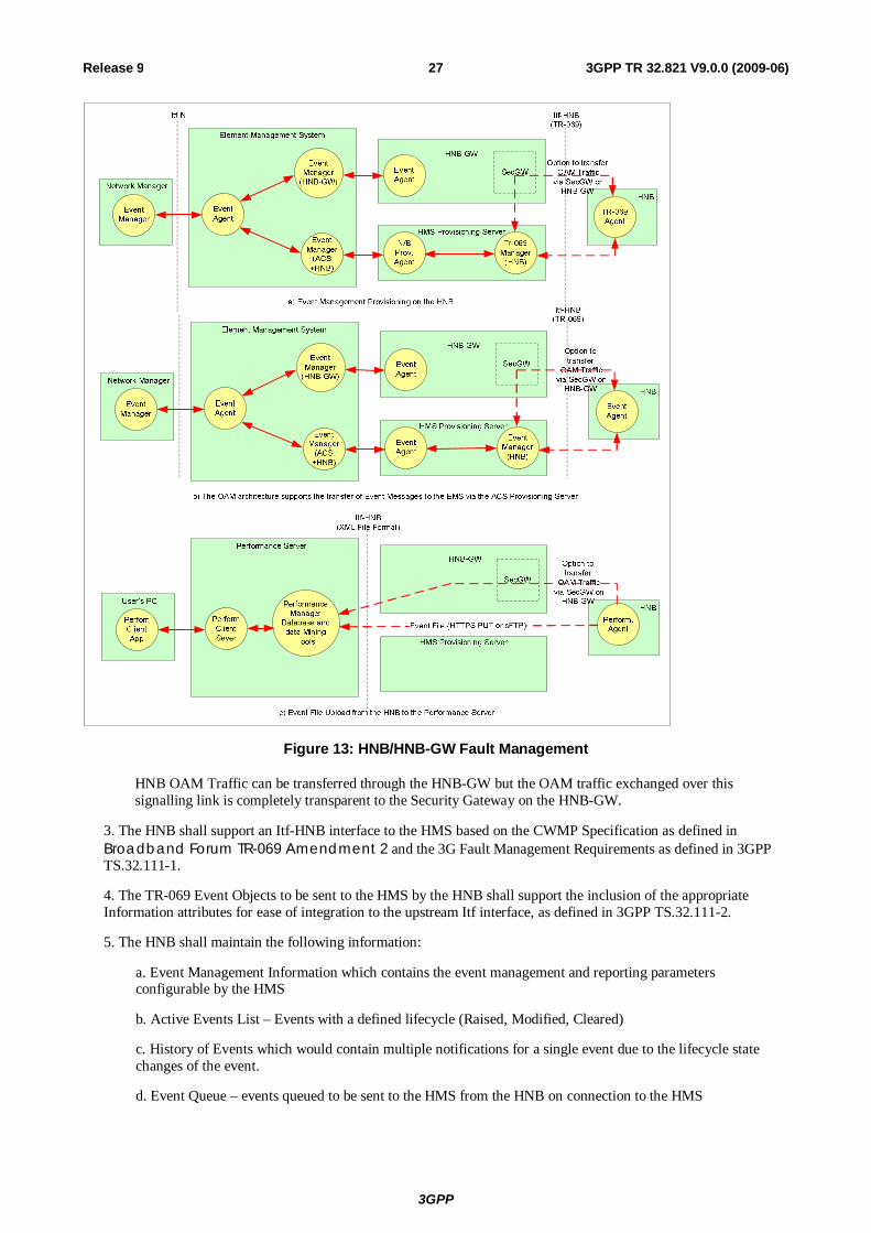
Figure 13: HNB/HNB-GW Fault Management
HNB OAM Traffic can be transferred through the HNB-GW but the OAM traffic exchanged over this signalling link is completely transparent to the Security Gateway on the HNB-GW.
3. The HNB shall support an Itf-HNB interface to the HMS based on the CWMP Specification as defined in Broadband Forum TR-069 Amendment 2 and the 3G Fault Management Requirements as defined in 3GPP TS.32.111-1.
4. The TR-069 Event Objects to be sent to the HMS by the HNB shall support the inclusion of the appropriate Information attributes for ease of integration to the upstream Itf interface, as defined in 3GPP TS.32.111-2.
5. The HNB shall maintain the following information:
a. Event Management Information which contains the event management and reporting parameters configurable by the HMS
b. Active Events List – Events with a defined lifecycle (Raised, Modified, Cleared)
c. History of Events which would contain multiple notifications for a single event due to the lifecycle state changes of the event.
d. Event Queue – events queued to be sent to the HMS from the HNB on connection to the HMS

3GPP
3GPP TR 32.821 V9.0.0 (2009-06) 28 Release 9
6. The HNB shall issue events to the HMS based on the configuration of the specific event’s reporting mechanism parameter
a. Active – the HNB connects to the HMS immediately to raise the event and logs the event in the Event History. If the event is configured with a lifecycle setting then the HNB updates the Active Events List.
b. Queue – the HNB queues the event internally pending connection to the HMS, logs the event in the Event History, and eventually delivers the event to the HMS as a result of one of the following:
i. periodic connection ii. connection to the HMS due to another reason
If the event is configured with a lifecycle setting then the HNB updates the Active Events List.
c. Log – the HNB stores the event in the Event History and can only be retrieved by the HMS by retrieving the Event History via TR-069 or requesting the uploading of an Event History File to the HMS.
If the event is configured with a lifecycle setting then the HNB updates the Active Events List.
d. Disabled – the HNB discards the event completely.
7. The HNB shall handle an event not configured in the HNB with Event Configuration Information with the same functionality used to handle a configured event with a notification setting of “Log”.
8. The HMS shall have the ability to throttle the sending of events from the HNB to the HMS by the following:
a. Setting of an overall HNB Event Forwarding Parameter
(1)Enabled – The HNB handles events as described in HNB-EMR-6 above (2)Moderate – The HNB handles events as described in HNB-EMR-6 above with the exception of restricting the number of alarms sent to the HMS within a certain time window as configured within the HNB Event Moderate Parameters. (3)BlockSending - The HNB handles events in HNB-EMR-6 above with the exception that alarms aren’t sent to the HMS and will remain in the HNB event queue even on HMS connection. The changing of the Event Forwarding Parameter to “Enabled” or “Moderate” will result in the events being flushed from the HNB to the HMS. (4)Disabled - The HNB handles events as described in HNB-EMR-6 above with the exception that alarms aren’t sent to the HMS and will not be placed on the HNB Event queue used to store pending events to be sent to the HMS.
b. Setting of the HNB Event Moderate Parameters which consists of the number of alarms to be sent per time unit and is used to spread the sending of events across a time window when the Event Forwarding Parameter is set to “Moderate”.
9. The HMS shall have the capability to retrieve any or all of the following from the HNB either via TR-069 RPC Method Calls or by requesting via TR-069 the uploading of an XML File with specific content from the HNB:
a. History of Events
b. Active Events List
10. The HMS shall have the capability to setup a periodic action on the HNB which instigates the producing and uploading of an XML File to the HMS with any or all of the following below information:
a. History of Events
b. Active Events List
11. The XML File Formats produced by the HNB shall be based on 3GPP XML File Formats which are based on W3C defined XML Schema and XML Namespace standards 12. The HMS shall have the capability to configure the HNB Events Configuration either via TR-069 RPC Method Calls 13. The HNB shall upload Files using one of the following mechanisms:
a. HTTPS PUT and GET with Username/Password
b. SFTP with Username/Password
3GPP
3GPP TR 32.821 V9.0.0 (2009-06) 29 Release 9
c. HTTP PUT with Username/Password
d. FTP with Username/Password
14. The HMS shall have the capability to clear events from the HNB Active Events List via TR-069 RPC Method Calls. 15. The HMS shall have the capability to completely purge one or all of the following held on the HNB:
a. History of Events
b. Active Events List
c. Pending Events Delivery Queue
6.2.1.3.2 Alarm Reporting
The number of Home Node Bs controlled by the OAM of one operator is expected to be very large, which presents challenges with respect to the scalability of the OAM traffic. At the same time, the number of users affected by the failure of one Home Node B will be relatively small. Therefore, the Home Node B should provide alarm information (including notifications and logs) only on demand from the OAM.
6.2.1.3.3 Faulty Conditions
OAM is not expected to collect alarms from Home Node Bs continuously; therefore, a Home Node B that detects a faulty condition from which it cannot immediately recover by its own means should eliminate any risk of negatively affecting the performance of surrounding Macro NodeBs and Home Node Bs. To ensure this:
- The Home Node B should stop radio transmission in case of faulty conditions negatively affecting the surrounding radio network;
Editor's Note: The list of these faulty conditions is FFS.
The Home Node B should stop radio transmission in case the backhaul link is lost.
6.2.1.3.4 Fault Management Method
FFS
6.2.1.3.5 Alarm Information
FFS
6.2.1.4 Security Management
FFS
6.2.1.5 Test Management
FFS
6.2.1.6 Subscription Management
FFS
6.2.2 HNB OAM Specification Level Requirement (Interface Type 2)
6.2.2.1 Self-Configuration
1. IRPManager should be able to set Home Node B Self- Configuration policy to allow IRPAgent to automatically initialize Home Node B.
3GPP
3GPP TR 32.821 V9.0.0 (2009-06) 30 Release 9
2. Home Node B should possess minimum information to automatically discover the transport layer address of the IRPManager
3. IRPAgent should notify IRPManager when Home Node B is operational.
6.2.2.2 Configuration Management
6.2.2.2.1 Configuration Data
It shall be possible to transfer a Home Node B configuration file containing configuration data from the IRPManager to the IRPAgent using Bulk CM IRP.
The IRPAgent shall be able to make the necessary configuration changes in its managed Home Node Bs, using the configuration data contained in the transferred configuration file.
The file format shall be independent of the data transfer protocol used to carry the file from one system to another.
6.2.2.3 Performance Management
6.2.2.3.1 Performance Management method
1. The DM for Home Node B should support PMIRP over Itf-N
6.2.2.4 Fault Management
6.2.2.4.1 Alarm Reporting
The DM for Home Node B should support AlarmIRP over Itf-N for managed Home Node Bs.
6.2.2.5 Subscriber Management
Home Node B may have a Closed Subscriber Group (CSG) access permission list. Only those subscribers who are in the CSG access permission list can camp on the Home Node B.
For each Home Node B, the detailed requirements for subscriber management are as follows:
1. IRPManager shall be able to provision the CSG access permission list of the Home Node B.
2. IRPManager shall be able to get the current CSG access permission list of the Home Node B from IRPAgent.
3. The CSG access permission list should be managed in a secure way.
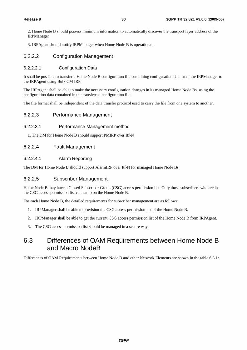
6.3 Differences of OAM Requirements between Home Node B and Macro NodeB
Differences of OAM Requirements between Home Node B and other Network Elements are shown in the table 6.3.1:
3GPP
3GPP TR 32.821 V9.0.0 (2009-06) 31 Release 9
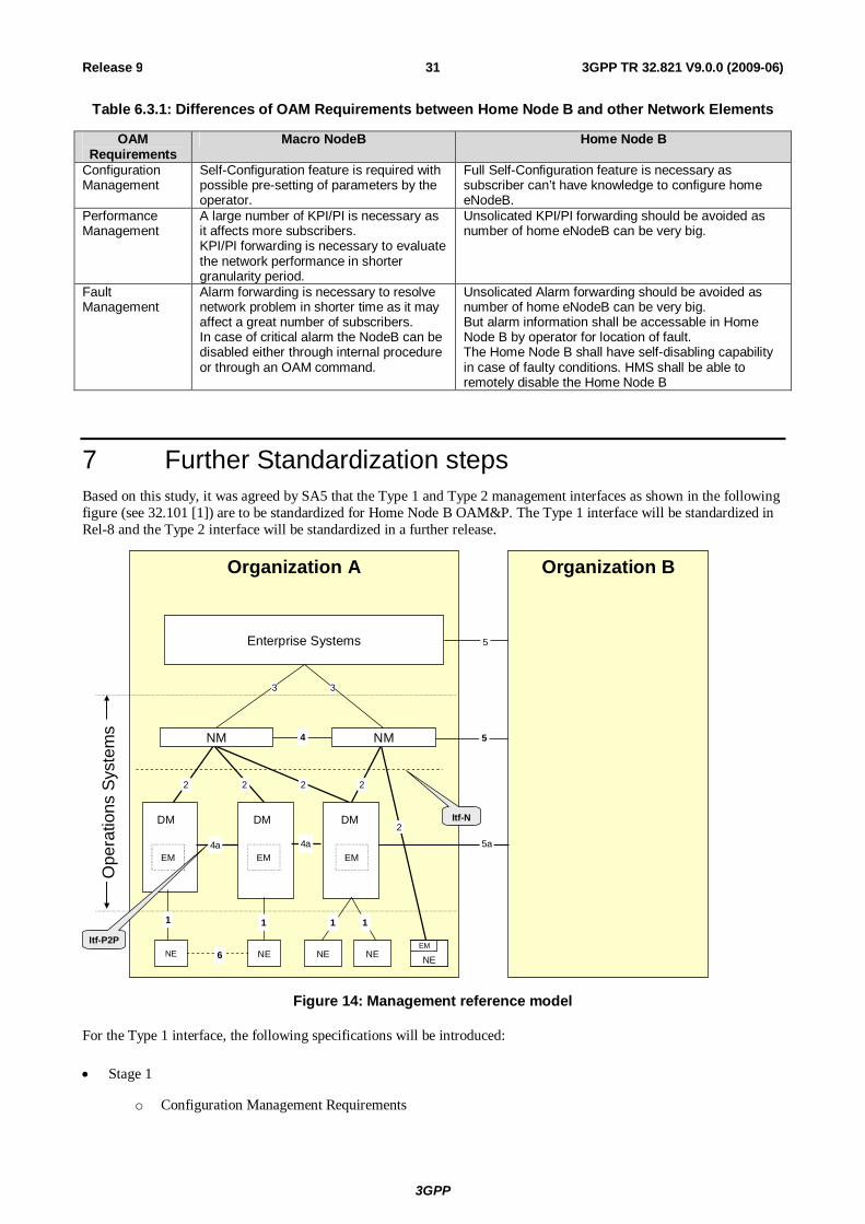
Table 6.3.1: Differences of OAM Requirements between Home Node B and other Network Elements
OAM Requirements
Macro NodeB Home Node B
Configuration Management
Self-Configuration feature is required with possible pre-setting of parameters by the operator.
Full Self-Configuration feature is necessary as subscriber can’t have knowledge to configure home eNodeB.
Performance Management
A large number of KPI/PI is necessary as it affects more subscribers. KPI/PI forwarding is necessary to evaluate the network performance in shorter granularity period.
Unsolicated KPI/PI forwarding should be avoided as number of home eNodeB can be very big.
Fault Management
Alarm forwarding is necessary to resolve network problem in shorter time as it may affect a great number of subscribers. In case of critical alarm the NodeB can be disabled either through internal procedure or through an OAM command.
Unsolicated Alarm forwarding should be avoided as number of home eNodeB can be very big. But alarm information shall be accessable in Home Node B by operator for location of fault. The Home Node B shall have self-disabling capability in case of faulty conditions. HMS shall be able to remotely disable the Home Node B
7 Further Standardization steps Based on this study, it was agreed by SA5 that the Type 1 and Type 2 management interfaces as shown in the following figure (see 32.101 [1]) are to be standardized for Home Node B OAM&P. The Type 1 interface will be standardized in Rel-8 and the Type 2 interface will be standardized in a further release.
Organization A
Enterprise Systems
NENENENEEM
NEEM
5
4 5
6
DM
Organization B
DM DM
2 2 2
4a 4a
2
1 1 1 1
5aEM EM EM
33
Itf-N
Ope
ratio
ns S
yste
ms
Itf-P2P
2
NM NM
Figure 14: Management reference model
For the Type 1 interface, the following specifications will be introduced:
Stage 1
o Configuration Management Requirements
3GPP
3GPP TR 32.821 V9.0.0 (2009-06) 32 Release 9
o Fault Management Requirements
o Performance Management Requirements
o OAM Security Requirements
Stage 2
o Architecture for HNB Management
o Object Classes for
Configuration Management for
HNB Access Network
Core Network (related to HNB)
Transport Network (related to HNB)
Fault Management
Performance Management
o Stage 2 for contents definition for CM, FM, PM & Logging
HNB to ACS procedure flows
o OAM Procedural flows for HNB Discovery, registration, config updates
o OAM Procedural flows for FM
o OAM Procedural flows for PM
Stage 3
o Data Format for CM, FM & PM (specified or referenced if required by stage 2)
3GPP
3GPP TR 32.821 V9.0.0 (2009-06) 33 Release 9
Annex A: FM data format definition This Annex describes the format of alarm reporting files that can be transferred from the network (NEs or EM) to the NM. The XML file format definition is based on XML schema (see [8], [9], [10], [11], [12], and [13]).
The XML file format definitions implement the alarm structure and parameters defined in 3GPP TS 32.111-2 [14].
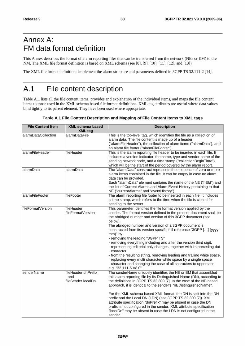
A.1 File content description Table A.1 lists all the file content items, provides and explanation of the individual items, and maps the file content items to those used in the XML schema based file format definitions. XML tag attributes are useful where data values bind tightly to its parent element. They have been used where appropriate.
Table A.1 File Content Description and Mapping of File Content Items to XML tags
File Content Item XML schema based XML tag
Description
alarmDataCollection alarmDataFile This is the top-level tag, which identifies the file as a collection of alarm data. The file content is made up of a header ("alarmFileHeader"), the collection of alarm items ("alarmData"), and an alarm file footer ("alarmFileFooter").
alarmFileHeader fileHeader This is the alarm reporting file header to be inserted in each file. It includes a version indicator, the name, type and vendor name of the sending network node, and a time stamp ("collectionBeginTime"), which will be the start of the period covered by the alarm report.
alarmData alarmData The "alarmData" construct represents the sequence of zero or more alarm items contained in the file. It can be empty in case no alarm data can be provided. Each "alarmData" element contains the name of the NE ("nEId") and the list of Current Alarms and Alarm Event History pertaining to that NE ("currentAlarms" and “eventHistory”).
alarmFileFooter fileFooter The alarm reporting file footer to be inserted in each file. It includes a time stamp, which refers to the time when the file is closed for sending to the server.
fileFormatVersion fileHeader fileFormatVersion
This parameter identifies the file format version applied by the sender. The format version defined in the present document shall be the abridged number and version of this 3GPP document (see below). The abridged number and version of a 3GPP document is constructed from its version specific full reference "3GPP […] (yyyy-mm)" by: - removing the leading "3GPP TS" - removing everything including and after the version third digit,
representing editorial only changes, together with its preceding dot character
- from the resulting string, removing leading and trailing white space, replacing every multi character white space by a single space character and changing the case of all characters to uppercase.
e.g. “32.111-6 V8.0” senderName fileHeader dnPrefix
and fileSender localDn
The senderName uniquely identifies the NE or EM that assembled this alarm reporting file by its Distinguished Name (DN), according to the definitions in 3GPP TS 32.300 [7]. In the case of the NE-based approach, it is identical to the sender's "nEDistinguishedName". For the XML schema based XML format, the DN is split into the DN prefix and the Local DN (LDN) (see 3GPP TS 32.300 [7]). XML attribute specification "dnPrefix" may be absent in case the DN prefix is not configured in the sender. XML attribute specification "localDn" may be absent in case the LDN is not configured in the sender.
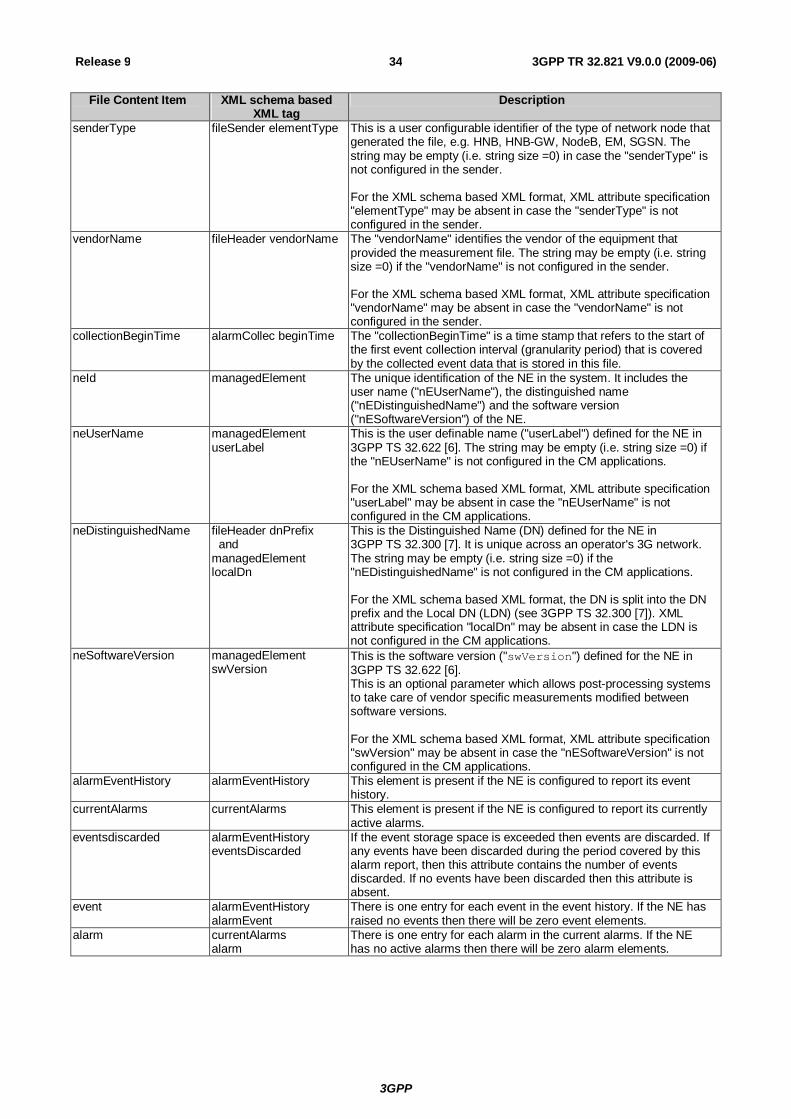
3GPP
3GPP TR 32.821 V9.0.0 (2009-06) 34 Release 9
File Content Item XML schema based XML tag
Description
senderType fileSender elementType This is a user configurable identifier of the type of network node that generated the file, e.g. HNB, HNB-GW, NodeB, EM, SGSN. The string may be empty (i.e. string size =0) in case the "senderType" is not configured in the sender. For the XML schema based XML format, XML attribute specification "elementType" may be absent in case the "senderType" is not configured in the sender.
vendorName fileHeader vendorName The "vendorName" identifies the vendor of the equipment that provided the measurement file. The string may be empty (i.e. string size =0) if the "vendorName" is not configured in the sender. For the XML schema based XML format, XML attribute specification "vendorName" may be absent in case the "vendorName" is not configured in the sender.
collectionBeginTime alarmCollec beginTime The "collectionBeginTime" is a time stamp that refers to the start of the first event collection interval (granularity period) that is covered by the collected event data that is stored in this file.
neId managedElement The unique identification of the NE in the system. It includes the user name ("nEUserName"), the distinguished name ("nEDistinguishedName") and the software version ("nESoftwareVersion") of the NE.
neUserName managedElement userLabel
This is the user definable name ("userLabel") defined for the NE in 3GPP TS 32.622 [6]. The string may be empty (i.e. string size =0) if the "nEUserName" is not configured in the CM applications. For the XML schema based XML format, XML attribute specification "userLabel" may be absent in case the "nEUserName" is not configured in the CM applications.
neDistinguishedName fileHeader dnPrefix and managedElement localDn
This is the Distinguished Name (DN) defined for the NE in 3GPP TS 32.300 [7]. It is unique across an operator's 3G network. The string may be empty (i.e. string size =0) if the "nEDistinguishedName" is not configured in the CM applications. For the XML schema based XML format, the DN is split into the DN prefix and the Local DN (LDN) (see 3GPP TS 32.300 [7]). XML attribute specification "localDn" may be absent in case the LDN is not configured in the CM applications.
neSoftwareVersion managedElement swVersion
This is the software version ("swVersion") defined for the NE in 3GPP TS 32.622 [6]. This is an optional parameter which allows post-processing systems to take care of vendor specific measurements modified between software versions. For the XML schema based XML format, XML attribute specification "swVersion" may be absent in case the "nESoftwareVersion" is not configured in the CM applications.
alarmEventHistory alarmEventHistory This element is present if the NE is configured to report its event history.
currentAlarms currentAlarms This element is present if the NE is configured to report its currently active alarms.
eventsdiscarded alarmEventHistory eventsDiscarded
If the event storage space is exceeded then events are discarded. If any events have been discarded during the period covered by this alarm report, then this attribute contains the number of events discarded. If no events have been discarded then this attribute is absent.
event alarmEventHistory alarmEvent
There is one entry for each event in the event history. If the NE has raised no events then there will be zero event elements.
alarm currentAlarms alarm
There is one entry for each alarm in the current alarms. If the NE has no active alarms then there will be zero alarm elements.
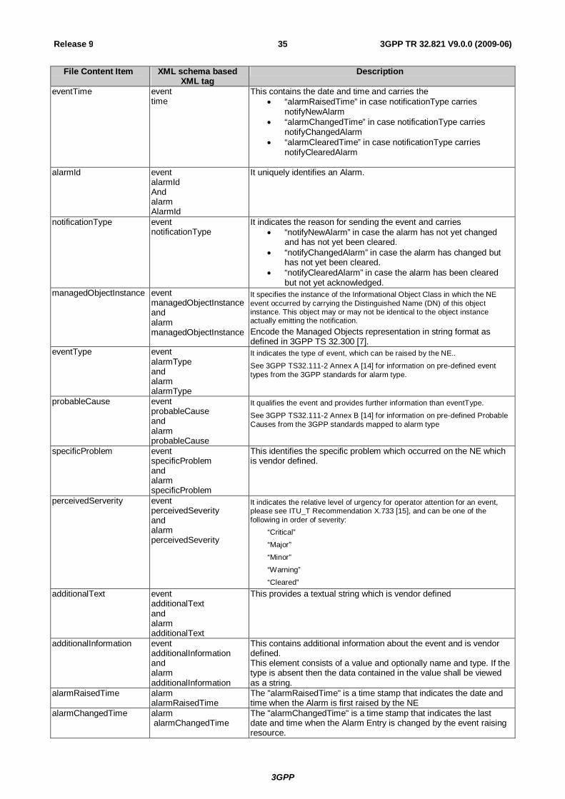
3GPP
3GPP TR 32.821 V9.0.0 (2009-06) 35 Release 9
File Content Item XML schema based XML tag
Description
eventTime event time
This contains the date and time and carries the “alarmRaisedTime” in case notificationType carries
notifyNewAlarm “alarmChangedTime” in case notificationType carries
notifyChangedAlarm “alarmClearedTime” in case notificationType carries
notifyClearedAlarm
alarmId event alarmId And alarm AlarmId
It uniquely identifies an Alarm.
notificationType event notificationType
It indicates the reason for sending the event and carries “notifyNewAlarm” in case the alarm has not yet changed
and has not yet been cleared. “notifyChangedAlarm” in case the alarm has changed but
has not yet been cleared. “notifyClearedAlarm” in case the alarm has been cleared
but not yet acknowledged. managedObjectInstance event
managedObjectInstance and alarm managedObjectInstance
It specifies the instance of the Informational Object Class in which the NE event occurred by carrying the Distinguished Name (DN) of this object instance. This object may or may not be identical to the object instance actually emitting the notification. Encode the Managed Objects representation in string format as defined in 3GPP TS 32.300 [7].
eventType event alarmType and alarm alarmType
It indicates the type of event, which can be raised by the NE..
See 3GPP TS32.111-2 Annex A [14] for information on pre-defined event types from the 3GPP standards for alarm type.
probableCause event probableCause and alarm probableCause
It qualifies the event and provides further information than eventType.
See 3GPP TS32.111-2 Annex B [14] for information on pre-defined Probable Causes from the 3GPP standards mapped to alarm type
specificProblem event specificProblem and alarm specificProblem
This identifies the specific problem which occurred on the NE which is vendor defined.
perceivedServerity event perceivedSeverity and alarm perceivedSeverity
It indicates the relative level of urgency for operator attention for an event, please see ITU_T Recommendation X.733 [15], and can be one of the following in order of severity:
“Critical”
“Major”
“Minor”
“Warning”
“Cleared” additionalText event
additionalText and alarm additionalText
This provides a textual string which is vendor defined
additionalInformation event additionalInformation and alarm additionalInformation
This contains additional information about the event and is vendor defined. This element consists of a value and optionally name and type. If the type is absent then the data contained in the value shall be viewed as a string.
alarmRaisedTime alarm alarmRaisedTime
The "alarmRaisedTime" is a time stamp that indicates the date and time when the Alarm is first raised by the NE
alarmChangedTime alarm alarmChangedTime
The "alarmChangedTime" is a time stamp that indicates the last date and time when the Alarm Entry is changed by the event raising resource.

3GPP
3GPP TR 32.821 V9.0.0 (2009-06) 36 Release 9
File Content Item XML schema based XML tag
Description
alarmClearedTime alarm alarmClearedTime
The "alarmClearedTime" is a time stamp that indicates the date and time when the Alarm Entry is Cleared by the NE
timeStamp alarmCollec endTime
A.2 XML schema based FM data file format definition
A.2.1 FM data file XML diagram Figure A.1 describes the XML element structure of the FM data file.

3GPP
3GPP TR 32.821 V9.0.0 (2009-06) 37 Release 9
Figure A.1: XML diagram of the alarm collection data file
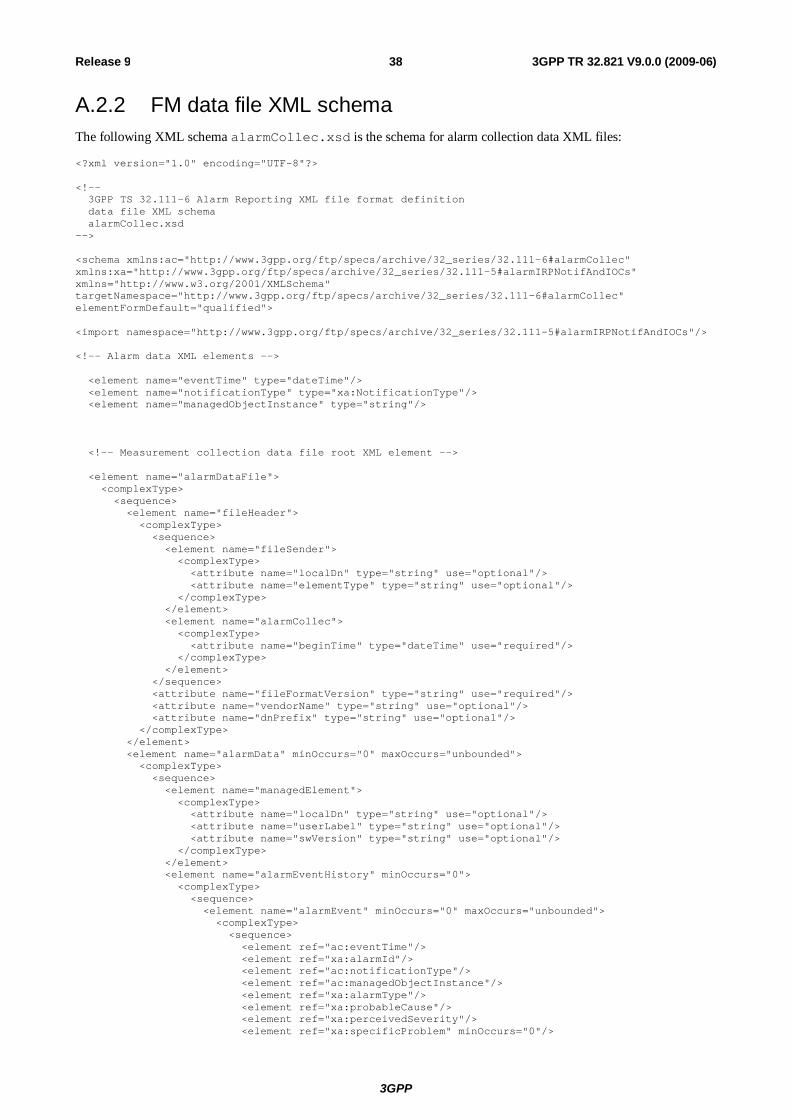
3GPP
3GPP TR 32.821 V9.0.0 (2009-06) 38 Release 9
A.2.2 FM data file XML schema The following XML schema alarmCollec.xsd is the schema for alarm collection data XML files:
<?xml version="1.0" encoding="UTF-8"?> <!-- 3GPP TS 32.111-6 Alarm Reporting XML file format definition data file XML schema alarmCollec.xsd --> <schema xmlns:ac="http://www.3gpp.org/ftp/specs/archive/32_series/32.111-6#alarmCollec" xmlns:xa="http://www.3gpp.org/ftp/specs/archive/32_series/32.111-5#alarmIRPNotifAndIOCs" xmlns="http://www.w3.org/2001/XMLSchema" targetNamespace="http://www.3gpp.org/ftp/specs/archive/32_series/32.111-6#alarmCollec" elementFormDefault="qualified"> <import namespace="http://www.3gpp.org/ftp/specs/archive/32_series/32.111-5#alarmIRPNotifAndIOCs"/> <!-- Alarm data XML elements --> <element name="eventTime" type="dateTime"/> <element name="notificationType" type="xa:NotificationType"/> <element name="managedObjectInstance" type="string"/> <!-- Measurement collection data file root XML element --> <element name="alarmDataFile"> <complexType> <sequence> <element name="fileHeader"> <complexType> <sequence> <element name="fileSender"> <complexType> <attribute name="localDn" type="string" use="optional"/> <attribute name="elementType" type="string" use="optional"/> </complexType> </element> <element name="alarmCollec"> <complexType> <attribute name="beginTime" type="dateTime" use="required"/> </complexType> </element> </sequence> <attribute name="fileFormatVersion" type="string" use="required"/> <attribute name="vendorName" type="string" use="optional"/> <attribute name="dnPrefix" type="string" use="optional"/> </complexType> </element> <element name="alarmData" minOccurs="0" maxOccurs="unbounded"> <complexType> <sequence> <element name="managedElement"> <complexType> <attribute name="localDn" type="string" use="optional"/> <attribute name="userLabel" type="string" use="optional"/> <attribute name="swVersion" type="string" use="optional"/> </complexType> </element> <element name="alarmEventHistory" minOccurs="0"> <complexType> <sequence> <element name="alarmEvent" minOccurs="0" maxOccurs="unbounded"> <complexType> <sequence> <element ref="ac:eventTime"/> <element ref="xa:alarmId"/> <element ref="ac:notificationType"/> <element ref="ac:managedObjectInstance"/> <element ref="xa:alarmType"/> <element ref="xa:probableCause"/> <element ref="xa:perceivedSeverity"/> <element ref="xa:specificProblem" minOccurs="0"/>
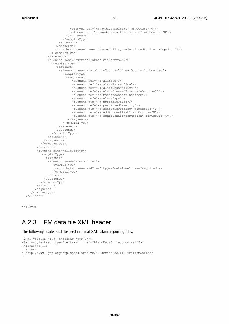
3GPP
3GPP TR 32.821 V9.0.0 (2009-06) 39 Release 9
<element ref="xa:additionalText" minOccurs="0"/> <element ref="xa:additionalInformation" minOccurs="0"/> </sequence> </complexType> </element> </sequence> <attribute name="eventsDiscarded" type="unsignedInt" use="optional"/> </complexType> </element> <element name="currentAlarms" minOccurs="0"> <complexType> <sequence> <element name="alarm" minOccurs="0" maxOccurs="unbounded"> <complexType> <sequence> <element ref="xa:alarmId"/> <element ref="xa:alarmRaisedTime"/> <element ref="xa:alarmChangedTime"/> <element ref="xa:alarmClearedTime" minOccurs="0"/> <element ref="ac:managedObjectInstance"/> <element ref="xa:alarmType"/> <element ref="xa:probableCause"/> <element ref="xa:perceivedSeverity"/> <element ref="xa:specificProblem" minOccurs="0"/> <element ref="xa:additionalText" minOccurs="0"/> <element ref="xa:additionalInformation" minOccurs="0"/> </sequence> </complexType> </element> </sequence> </complexType> </element> </sequence> </complexType> </element> <element name="fileFooter"> <complexType> <sequence> <element name="alarmCollec"> <complexType> <attribute name="endTime" type="dateTime" use="required"/> </complexType> </element> </sequence> </complexType> </element> </sequence> </complexType> </element> </schema>
A.2.3 FM data file XML header The following header shall be used in actual XML alarm reporting files:
<?xml version="1.0" encoding="UTF-8"?> <?xml-stylesheet type="text/xsl" href="AlarmDataCollection.xsl"?> <AlarmDataFile xmlns= " http://www.3gpp.org/ftp/specs/archive/32_series/32.111-6#alarmCollec" >
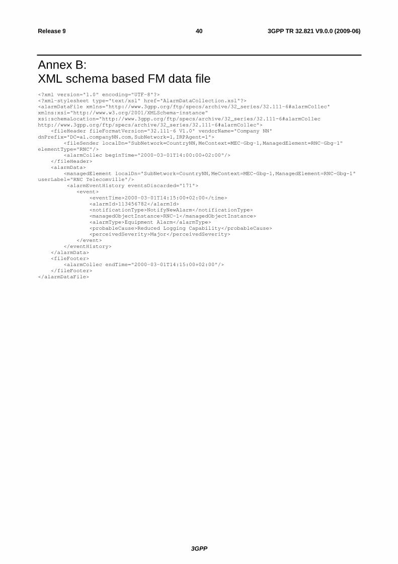
3GPP
3GPP TR 32.821 V9.0.0 (2009-06) 40 Release 9
Annex B: XML schema based FM data file <?xml version="1.0" encoding="UTF-8"?> <?xml-stylesheet type="text/xsl" href="AlarmDataCollection.xsl"?> <alarmDataFile xmlns="http://www.3gpp.org/ftp/specs/archive/32_series/32.111-6#alarmCollec" xmlns:xsi="http://www.w3.org/2001/XMLSchema-instance" xsi:schemaLocation="http://www.3gpp.org/ftp/specs/archive/32_series/32.111-6#alarmCollec http://www.3gpp.org/ftp/specs/archive/32_series/32.111-6#alarmCollec"> <fileHeader fileFormatVersion="32.111-6 V1.0" vendorName="Company NN" dnPrefix="DC=a1.companyNN.com,SubNetwork=1,IRPAgent=1"> <fileSender localDn="SubNetwork=CountryNN,MeContext=MEC-Gbg-1,ManagedElement=RNC-Gbg-1" elementType="RNC"/> <alarmCollec beginTime="2000-03-01T14:00:00+02:00"/> </fileHeader> <alarmData> <managedElement localDn="SubNetwork=CountryNN,MeContext=MEC-Gbg-1,ManagedElement=RNC-Gbg-1" userLabel="RNC Telecomville"/> <alarmEventHistory eventsDiscarded="171"> <event> <eventTime>2000-03-01T14:15:00+02:00</time> <alarmId>113456782</alarmId> <notificationType>NotifyNewAlarm</notificationType> <managedObjectInstance>RNC-1</managedObjectInstance> <alarmType>Equipment Alarm</alarmType> <probableCause>Reduced Logging Capability</probableCause> <perceivedSeverity>Major</perceivedSeverity> </event> </eventHistory> </alarmData> <fileFooter> <alarmCollec endTime="2000-03-01T14:15:00+02:00"/> </fileFooter> </alarmDataFile>

3GPP
3GPP TR 32.821 V9.0.0 (2009-06) 41 Release 9
Annex C: Change history
Change history Date TSG # TSG Doc. CR Rev Subject/Comment Old New Dec 2008 SP-42 SP-080847 Submitted to SA#42 for Information 0.3.0 1.0.0 Jun 2009 SP-44 SP-090297 Submission to SA#44 for approval 2.0.0 9.0.0