
TECHNICAL DATA TYPE CZ VACUUM ON-LOAD … · TECHNICAL DATA TYPE CZ VACUUM ON-LOAD TAP CHANGER FOR...
24
SHANGHAI HUAMING POWER EQUIPMENT CO., LTD. TECHNICAL DATA TYPE CZ VACUUM ON-LOAD TAP CHANGER FOR DRY TYPE TRANSFORMER HM0.154.1102
Transcript of TECHNICAL DATA TYPE CZ VACUUM ON-LOAD … · TECHNICAL DATA TYPE CZ VACUUM ON-LOAD TAP CHANGER FOR...
SHANGHAI HUAMING POWER EQUIPMENT CO., LTD.
TECHNICAL DATATYPE CZ VACUUM ON-LOAD TAP CHANGERFOR DRY TYPE TRANSFORMERHM0.154.1102
HM0.154.1102
TYPE CZ VACUUM ON-LOAD TAP CHANGER TECHNICAL DATA
1
1. General⋯⋯⋯⋯⋯⋯⋯⋯⋯⋯⋯⋯⋯⋯⋯⋯⋯⋯⋯⋯⋯⋯⋯⋯⋯⋯⋯⋯⋯⋯⋯⋯⋯⋯⋯⋯⋯⋯⋯⋯⋯⋯⋯⋯⋯2 2. Technical specifications ⋯⋯⋯⋯⋯⋯⋯⋯⋯⋯⋯⋯⋯⋯⋯⋯⋯⋯⋯⋯⋯⋯⋯⋯⋯⋯⋯⋯⋯⋯⋯⋯⋯⋯⋯⋯⋯⋯33. Model designation ⋯⋯⋯⋯⋯⋯⋯⋯⋯⋯⋯⋯⋯⋯⋯⋯⋯⋯⋯⋯⋯⋯⋯⋯⋯⋯⋯⋯⋯⋯⋯⋯⋯⋯⋯⋯⋯⋯⋯⋯44. Terms and definitions ⋯⋯⋯⋯⋯⋯⋯⋯⋯⋯⋯⋯⋯⋯⋯⋯⋯⋯⋯⋯⋯⋯⋯⋯⋯⋯⋯⋯⋯⋯⋯⋯⋯⋯⋯⋯⋯⋯⋯55. Special design⋯⋯⋯⋯⋯⋯⋯⋯⋯⋯⋯⋯⋯⋯⋯⋯⋯⋯⋯⋯⋯⋯⋯⋯⋯⋯⋯⋯⋯⋯⋯⋯⋯⋯⋯⋯⋯⋯⋯⋯⋯⋯66. Motor drive unit ⋯⋯⋯⋯⋯⋯⋯⋯⋯⋯⋯⋯⋯⋯⋯⋯⋯⋯⋯⋯⋯⋯⋯⋯⋯⋯⋯⋯⋯⋯⋯⋯⋯⋯⋯⋯⋯⋯⋯⋯⋯77. Operation controllers ⋯⋯⋯⋯⋯⋯⋯⋯⋯⋯⋯⋯⋯⋯⋯⋯⋯⋯⋯⋯⋯⋯⋯⋯⋯⋯⋯⋯⋯⋯⋯⋯⋯⋯⋯⋯⋯⋯⋯78. Accessories ⋯⋯⋯⋯⋯⋯⋯⋯⋯⋯⋯⋯⋯⋯⋯⋯⋯⋯⋯⋯⋯⋯⋯⋯⋯⋯⋯⋯⋯⋯⋯⋯⋯⋯⋯⋯⋯⋯⋯⋯⋯⋯⋯89. Appendixes ⋯⋯⋯⋯⋯⋯⋯⋯⋯⋯⋯⋯⋯⋯⋯⋯⋯⋯⋯⋯⋯⋯⋯⋯⋯⋯⋯⋯⋯⋯⋯⋯⋯⋯⋯⋯⋯⋯⋯⋯⋯⋯⋯8Appendix 1 CZI OLTC overall dimension,9 operation positions ⋯⋯⋯⋯⋯⋯⋯⋯⋯⋯⋯⋯⋯⋯⋯⋯⋯⋯⋯⋯⋯⋯9Appendix 2 CZI OLTC overall dimension,7 operation positions⋯⋯⋯⋯⋯⋯⋯⋯⋯⋯⋯⋯⋯⋯⋯⋯⋯⋯⋯⋯⋯⋯10Appendix 3 CZI OLTC overall dimension,13 operation positions ⋯⋯⋯⋯⋯⋯⋯⋯⋯⋯⋯⋯⋯⋯⋯⋯⋯⋯⋯⋯⋯11Appendix 4 CZ OLTC mounted on supporting frame, MDU on the right side, 9 positions⋯⋯⋯⋯⋯⋯⋯⋯⋯⋯⋯12Appendix 5 CZ OLTC mounted on supporting frame, MDU on the left side,9 positions⋯⋯⋯⋯⋯⋯⋯⋯⋯⋯⋯⋯13Appendix 6 CZ OLTC mounted in enclosure, MDU on the right side, 7 positions⋯⋯⋯⋯⋯⋯⋯⋯⋯⋯⋯⋯⋯⋯⋯14Appendix 7 CZ OLTC mounted in enclosure, MDU on the left side, 7 positions⋯⋯⋯⋯⋯⋯⋯⋯⋯⋯⋯⋯⋯⋯⋯15Appendix 8 CZ OLTC mounted in enclosure, MDU on the right side, 9 positions ⋯⋯⋯⋯⋯⋯⋯⋯⋯⋯⋯⋯⋯⋯16Appendix 9 CZ OLTC mounted in enclosure, MDU on the left side, 9 positions⋯⋯⋯⋯⋯⋯⋯⋯⋯⋯⋯⋯⋯⋯⋯17Appendix 10 Disposal drawing of 3 units of single phase CZ OLTC⋯⋯⋯⋯⋯⋯⋯⋯⋯⋯⋯⋯⋯⋯⋯⋯⋯⋯⋯⋯18Appendix 11 Installation dimension of SHM-III motor drive unit⋯⋯⋯⋯⋯⋯⋯⋯⋯⋯⋯⋯⋯⋯⋯⋯⋯⋯⋯⋯⋯⋯19Appendix 12 Installation dimension of CMA7 motor drive unit ⋯⋯⋯⋯⋯⋯⋯⋯⋯⋯⋯⋯⋯⋯⋯⋯⋯⋯⋯⋯⋯⋯20Appendix 13 Installation dimension of bevel gearbox⋯⋯⋯⋯⋯⋯⋯⋯⋯⋯⋯⋯⋯⋯⋯⋯⋯⋯⋯⋯⋯⋯⋯⋯⋯⋯21Appendix 14 Schematic drawing of horizontal insulation drive shaft⋯⋯⋯⋯⋯⋯⋯⋯⋯⋯⋯⋯⋯⋯⋯⋯⋯⋯⋯⋯22
General
HM0.154.1102
TYPE CZ VACUUM ON-LOAD TAP CHANGER TECHNICAL DATA
2
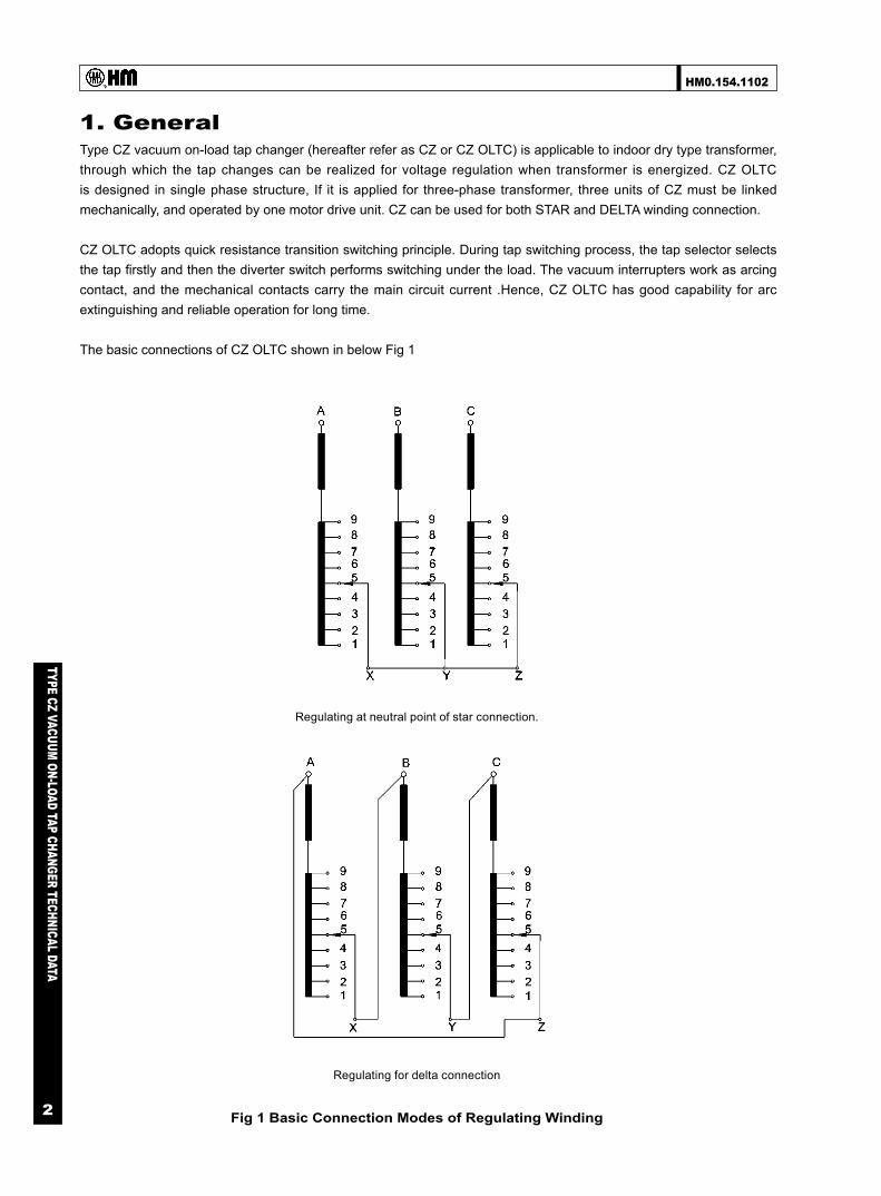
1. General Type CZ vacuum on-load tap changer (hereafter refer as CZ or CZ OLTC) is applicable to indoor dry type transformer, through which the tap changes can be realized for voltage regulation when transformer is energized. CZ OLTC is designed in single phase structure, If it is applied for three-phase transformer, three units of CZ must be linked mechanically, and operated by one motor drive unit. CZ can be used for both STAR and DELTA winding connection.
CZ OLTC adopts quick resistance transition switching principle. During tap switching process, the tap selector selects the tap firstly and then the diverter switch performs switching under the load. The vacuum interrupters work as arcing contact, and the mechanical contacts carry the main circuit current .Hence, CZ OLTC has good capability for arc extinguishing and reliable operation for long time.
The basic connections of CZ OLTC shown in below Fig 1
Regulating at neutral point of star connection.
Regulating for delta connection
Fig 1 Basic Connection Modes of Regulating Winding

HM0.154.1102
TYPE CZ VACUUM ON-LOAD TAP CHANGER TECHNICAL DATA
3
Table 1 Type CZ Vacuum OLTC Technical Parameters
2. Technical specifications
CZ OLTC is designed and manufactured according to IEC60214-1:2003. Please refer to Table 1 for the technical specifications.
No. On Load Tap Changer CZ500 3 × CZ500
1 Number of Phase And Application 1 Single Phase
3 Any 3-phaseConnection
2 Max. Rated Through-Current (A) 500
3Short-circuit
current test (kA)
Thermal (3s) 5
Dynamic (Peak) 12.5
4 Max. Rated Step Voltage (V) 900
5 Rated Step Capacity (kVA) 250
6 Max. Operating Positions 13, in linear regulation
7 Rated Frequency (Hz) 50 or 60
8InsulationTo Ground
Highest Voltage For Equipment Um (kV) 40.5
Rated separate source ACwithstand voltage(kV/50Hz,1min)
85
Rated lightning impulsewithstand voltage (kV,1.2/50μs)
200
9Internal
Insulation
Between TapIn Service AndPre-Selected
Tap
Rated separate source ACwithstand voltage(kV/50Hz,1min)
5
Rated lightning impulsewithstand voltage (kV,1.2/50μs)
20
Across FineTap Winding
Rated separate source ACwithstand voltage(kV/50Hz,1min)
20
Rated lightning impulsewithstand voltage (kV,1.2/50μs)
80
10 Ambient Temperature of Operation (℃ ) -25~+65
11 Ambient Media of Operation Air
12 Adopted Motor Drive Unit SHM-III or CMA7
13 Electric Life Not Less Than 300,000 Operations
14 Mechanical Life Not Less Than 800,000 Operations
15 OLTC Weight (Excluding Motor Drive Unit, Approx.) 80 240
HM0.154.1102
TYPE CZ VACUUM ON-LOAD TAP CHANGER TECHNICAL DATA
4
3. Model designation
3.1 Description of model
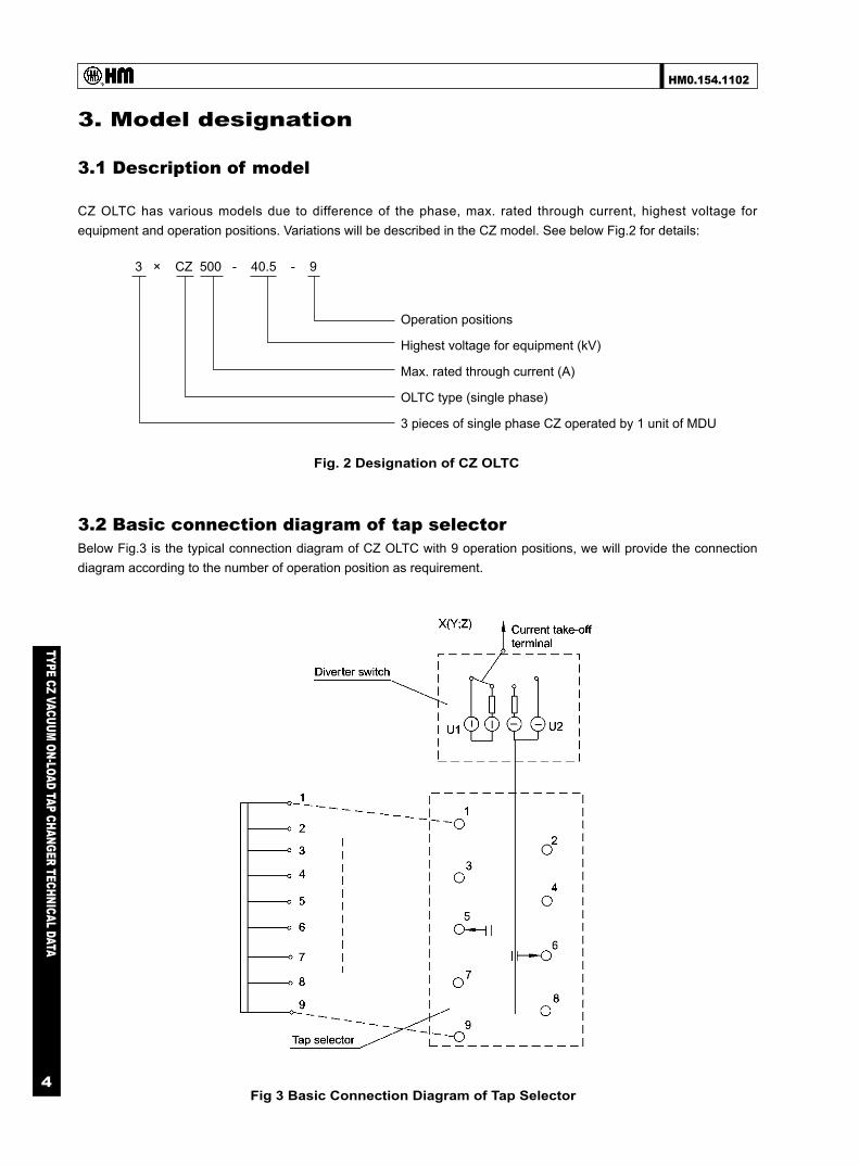
CZ OLTC has various models due to difference of the phase, max. rated through current, highest voltage for equipment and operation positions. Variations will be described in the CZ model. See below Fig.2 for details:
Fig. 2 Designation of CZ OLTC
Fig 3 Basic Connection Diagram of Tap Selector
3.2 Basic connection diagram of tap selector Below Fig.3 is the typical connection diagram of CZ OLTC with 9 operation positions, we will provide the connection diagram according to the number of operation position as requirement.
3 × CZ 500 - 40.5 - 9
Operation positions
Highest voltage for equipment (kV)
Max. rated through current (A)
OLTC type (single phase)
3 pieces of single phase CZ operated by 1 unit of MDU

HM0.154.1102
TYPE CZ VACUUM ON-LOAD TAP CHANGER TECHNICAL DATA
5
Fig 4 Curve of CZ OLTC Rated Step Capacity
4. Terms and definitions
4.1 Through current Rated through current Iu: The current flowing through an OLTC towards the external circuit, which the apparatus is capable of transferring from one tap to the other at the relevant rated step voltage and which can be carried continuously while meeting the requirement.
Max. rated through current Ium: The highest rated through-current for which the tap changer is designed for and which forms the basis for all current related tests.
4.2 Step voltage Rated step voltage (Ui) For each value of rated through-current, the highest permissible voltage between terminals which are intended to be connected to successive taps of the transformer.
Maximum rated step voltage (Uim) The highest value of the rated step voltage for which the tap-changer is designed.
4.3 Rated step capacity PStN
The rated step capacity is determined by OLTC circuit structure and breaking capacity of vacuum interrupter.
According to Fig.4 Curve of CZ OLTC Rated Step Capacity., the max. rated through current versus the associated step voltage of the OLTC can be determined.
4.4 Breaking capacity According to IEC60214-1 (2003), Forty operations shall be performed at a current corresponding to twice the maximum rated through-current and at its relevant rated step voltage. The OLTC breaking capacity Pst.max= 2 PStN≈2 Ium×UStN Where, PStN is rated step capacity Ium is max. rated through current UStN is relevant step voltage

HM0.154.1102
TYPE CZ VACUUM ON-LOAD TAP CHANGER TECHNICAL DATA
6
4.5 Short-circuit current test According to IEC 60214-1: 2003, all contacts continuously carrying the current shall be able to withstand 2s (±10%) short circuit test current without melting, deformation or mechanical damage. Meanwhile the starting peak current value shall be 2.5 (±5%) times of the root means square value of rated short circuit test current. Refer the short circuit test current values to Table 1.Type CZ Vacuum OLTC Technical Parameters.
4.6 Ambient air temperature CZ OLTC is for indoor application,the CZ OLTC can be applied where ambient air temperature ranges from -25℃ to +65℃ . Measures should be taken to avoid condensation and freeze on the OLTC.
4.7 Insulation level Insulation level of type CZ is including insulation to ground and internal insulation. Insulation to ground is considered as 40.5kV insulation grade, and internal insulation level of CZ OLTC is according to the insulation grades satisfied to each part of a common dry transformer, see details in below Table 2
4.8 Installation of CZ OLTC
CZ OLTC shall be fixed on a supporting frame by its upper insulation plate. The supporting frame could be a part of transformer frame prepared by transformer manufacturer.
We can also provide the supporting frame or cabinet according to the requirements.
5. Special design
The special design of CZ OLTC mainly refers to tap positions location scheme on OLTC and number of operation positions. Up to date, we can provide the maximum operation positions up to 13 for linear regulation mode.
CZ OLTC can be provided together with supporting frame or cabinet according to customer's requirement. see details in Appendix.
Table 2 CZ OLTC Insulation Level
Note: If transformer is placed in a cabinet grounded, sufficient insulation space should be considered between OLTC live parts and the transformer cabinet.
Insulation level Rated separate source AC withstandvoltage (kV/50Hz, 1min)
Rated lightning impulse withstandvoltage (kV, 1.2/50μs)
To ground and between phases 85 200
Between adjacent taps 5 20
Across fine tap winding 20 80
(unit: kV)
HM0.154.1102
TYPE CZ VACUUM ON-LOAD TAP CHANGER TECHNICAL DATA
7
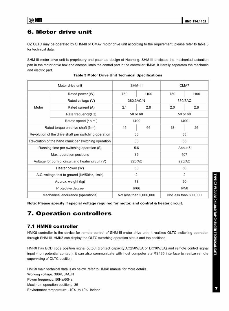
6. Motor drive unit
CZ OLTC may be operated by SHM-III or CMA7 motor drive unit according to the requirement, please refer to table 3 for technical data.
SHM-III motor drive unit is proprietary and patented design of Huaming. SHM-III encloses the mechanical actuation part in the motor drive box and encapsulates the control part in the controller HMK8. It literally separates the mechanic and electric part.
7. Operation controllers
7.1 HMK8 controller HMK8 controller is the device for remote control of SHM-III motor drive unit; it realizes OLTC switching operation through SHM-III. HMK8 can display the OLTC switching operation status and tap positions.
HMK8 has BCD code position signal output (contact capacity:AC250V/5A or DC30V/5A) and remote control signal input (non potential contact), it can also communicate with host computer via RS485 interface to realize remote supervising of OLTC position.
HMK8 main technical data is as below, refer to HMK8 manual for more details. Working voltage: 380V, 3AC/N Power frequency: 50Hz/60Hz Maximum operation positions: 35 Environment temperature: -10℃ to 40℃ Indoor
Motor drive unit SHM-III CMA7
Motor
Rated power (W) 750 1100 750 1100
Rated voltage (V) 380,3AC/N 380/3AC
Rated current (A) 2.1 2.8 2.0 2.8
Rate frequency(Hz) 50 or 60 50 or 60
Rotate speed (r.p.m.) 1400 1400
Rated torque on drive shaft (Nm) 45 66 18 26
Revolution of the drive shaft per switching operation 33 33
Revolution of the hand crank per switching operation 33 33
Running time per switching operation (S) 5.6 About 5
Max. operation positions 35 107
Voltage for control circuit and heater circuit (V) 220/AC 220/AC
Heater power (W) 50 50
A.C. voltage test to ground (kV/50Hz, 1min) 2 2
Approx. weight (kg) 73 90
Protective degree IP66 IP56
Mechanical endurance (operations) Not less than 2,000,000 Not less than 800,000
Table 3 Motor Drive Unit Technical Specifications
Note: Please specify if special voltage required for motor, and control & heater circuit.

HM0.154.1102
TYPE CZ VACUUM ON-LOAD TAP CHANGER TECHNICAL DATA
8
7.2 HMC-3C position indicator HMC-3C OLTC position indicator is a support fitting for CMA7 and CMA9 motor drive unit, it can be used to indicate the OLTC position, and has the function of "1→ N", "STOP", "N→ 1" control as well as remote control indicator lamp, its input is decimal code and output is BCD code. HMC-3C technical data is as below, refer to manual for more details. Working voltage: 220V AC Power frequency: 50Hz Maximum operation positions: 107 Environment temperature: -10℃ to 40℃ Indoor
7.3 Automatic voltage regulator ET-SZ6 and HMK-2A Automatic voltage regulator ET-SZ6 and HMK-2A is adopted for OLTC automatic voltage regulation, ET-SZ6 can be used for parallel operation in model of master and slave, please refer to relevant manual for details.
8. Accessories
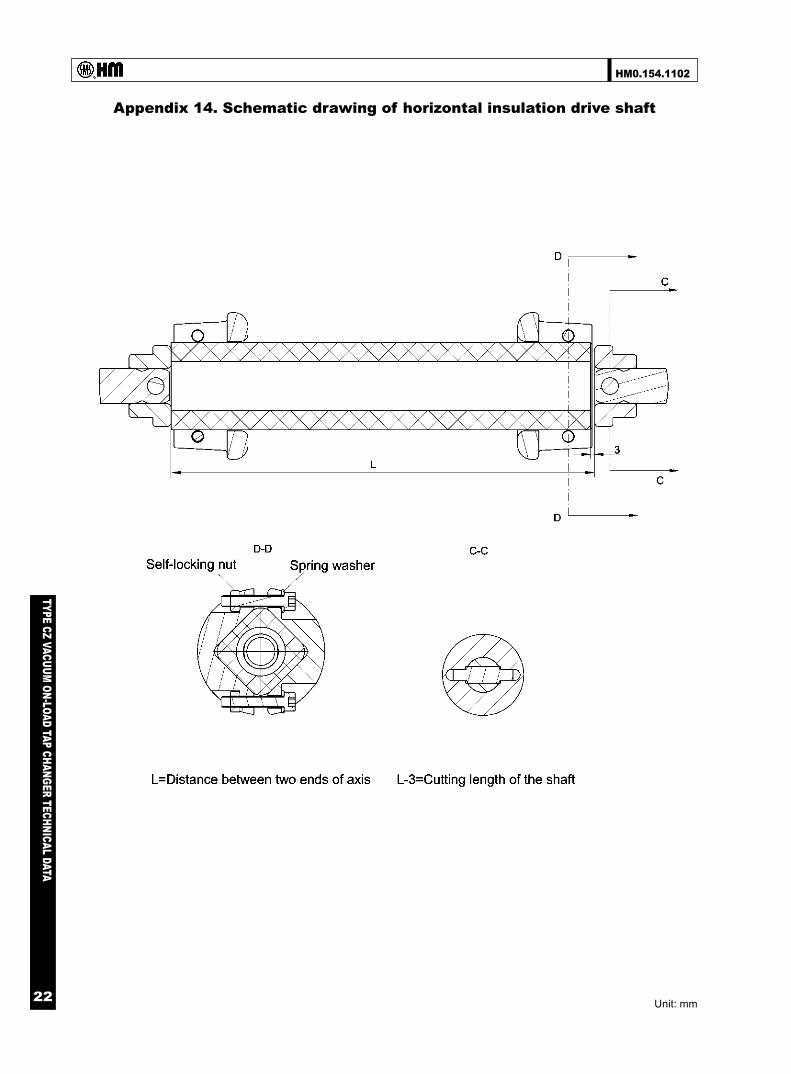
8.1 Horizontal shaft and vertical shaft The horizontal shaft and vertical shaft is used for connection of the tap changer and motor drive unit via bevel gearbox.
The horizontal shaft is made from high strength insulation material, Its length will be determined by the insulation level required between phases when the tap changer is mounted on the transformer.
The vertical shaft is made of stainless steel.
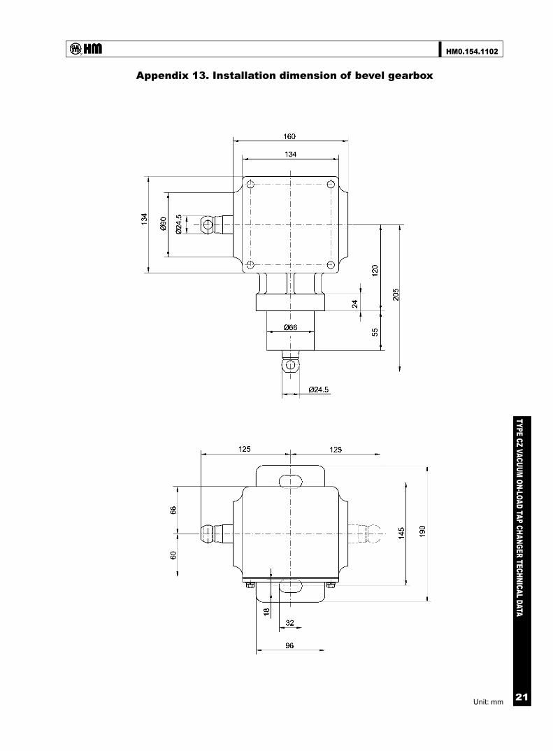
8.2 Bevel gear box
The bevel gearbox connects the horizontal shaft of tap changer body and the vertical shaft of motor drive unit, it transmit the drive torque from motor drive unit to the tap changer. See installation dimension of bevel gearbox in Appendix 13.
9. Appendixes

HM0.154.1102
TYPE CZ VACUUM ON-LOAD TAP CHANGER TECHNICAL DATA
9
Appendix 1. CZI OLTC overall dimension 9 operation positions
Unit: mm
HM0.154.1102
TYPE CZ VACUUM ON-LOAD TAP CHANGER TECHNICAL DATA
10
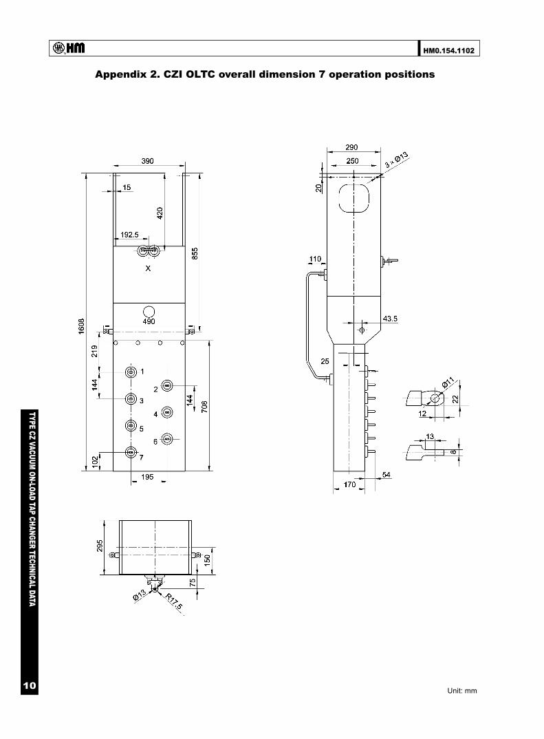
Appendix 2. CZI OLTC overall dimension 7 operation positions
Unit: mm
HM0.154.1102
TYPE CZ VACUUM ON-LOAD TAP CHANGER TECHNICAL DATA
11
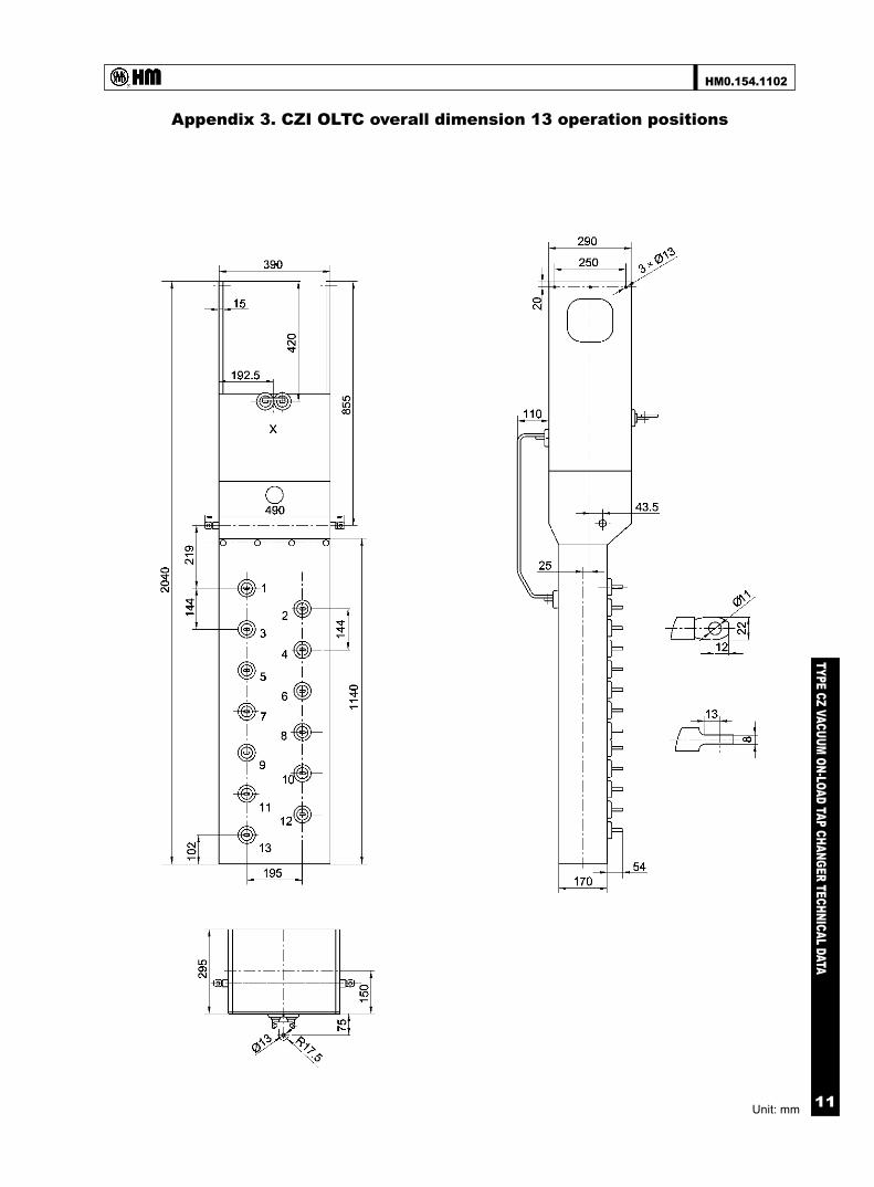
Appendix 3. CZI OLTC overall dimension 13 operation positions
Unit: mm
HM0.154.1102
TYPE CZ VACUUM ON-LOAD TAP CHANGER TECHNICAL DATA
12
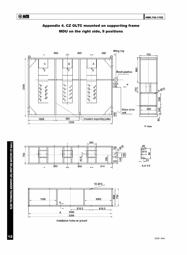
Appendix 4. CZ OLTC mounted on supporting frame MDU on the right side, 9 positions
Unit: mm

HM0.154.1102
TYPE CZ VACUUM ON-LOAD TAP CHANGER TECHNICAL DATA
13
Appendix 5. CZ OLTC mounted on supporting frameMDU on the left side,9 positions
Unit: mm
HM0.154.1102
TYPE CZ VACUUM ON-LOAD TAP CHANGER TECHNICAL DATA
14
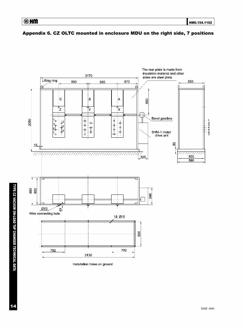
Appendix 6. CZ OLTC mounted in enclosure MDU on the right side, 7 positions
Unit: mm

HM0.154.1102
TYPE CZ VACUUM ON-LOAD TAP CHANGER TECHNICAL DATA
15
Appendix 7. CZ OLTC mounted in enclosure MDU on the left side, 7 positions
Unit: mm
HM0.154.1102
TYPE CZ VACUUM ON-LOAD TAP CHANGER TECHNICAL DATA
16
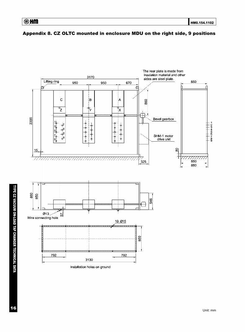
Appendix 8. CZ OLTC mounted in enclosure MDU on the right side, 9 positions
Unit: mm

HM0.154.1102
TYPE CZ VACUUM ON-LOAD TAP CHANGER TECHNICAL DATA
17
Appendix 9. CZ OLTC mounted in enclosure MDU on the left side, 9 positions
Unit: mm

HM0.154.1102
TYPE CZ VACUUM ON-LOAD TAP CHANGER TECHNICAL DATA
18
Appendix 10. Disposal drawing of 3 units of single phase CZ OLTC
Unit: mm
HM0.154.1102
TYPE CZ VACUUM ON-LOAD TAP CHANGER TECHNICAL DATA
19
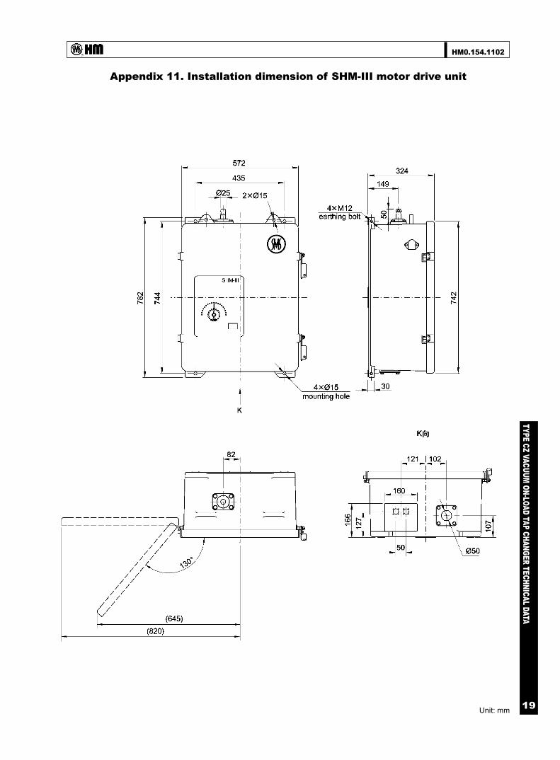
Appendix 11. Installation dimension of SHM-III motor drive unit
Unit: mm
HM0.154.1102
TYPE CZ VACUUM ON-LOAD TAP CHANGER TECHNICAL DATA
20
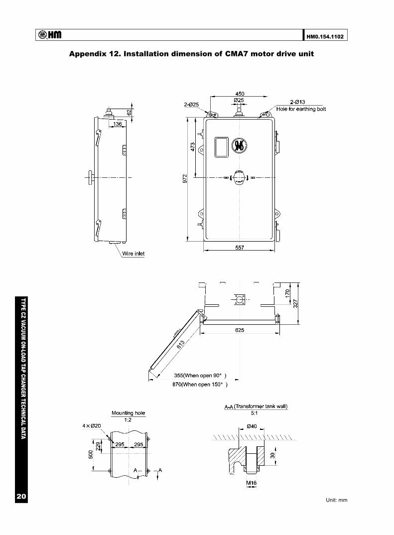
Appendix 12. Installation dimension of CMA7 motor drive unit
Unit: mm
HM0.154.1102
TYPE CZ VACUUM ON-LOAD TAP CHANGER TECHNICAL DATA
21
Appendix 13. Installation dimension of bevel gearbox
Unit: mm
HM0.154.1102
TYPE CZ VACUUM ON-LOAD TAP CHANGER TECHNICAL DATA
22
Appendix 14. Schematic drawing of horizontal insulation drive shaft
Unit: mm

69
TYPE VCM O
IL-IMM
ERSED ON
-LOAD TAP CH
ANG
ER TECHN
ICAL DATA
HM0.154.5701
Printing: FEB.2010
SHANGHAI HUAMING POWER EQUIPMENT CO., LTD.
Address: 977 Tong Pu Road, Shanghai, P.R.China 200333Tel: +86 21 5270 3965(direct)
+86 21 5270 8966 Ext.8688/8123/8698/8158/8110/8658
Fax: +86 21 5270 2715Web:www.huaming.com
E-mail: [email protected]