Table of Contents - Toboa Energy Resources LLC · submersible pump is the same as a standard AC...
17
Transcript of Table of Contents - Toboa Energy Resources LLC · submersible pump is the same as a standard AC...

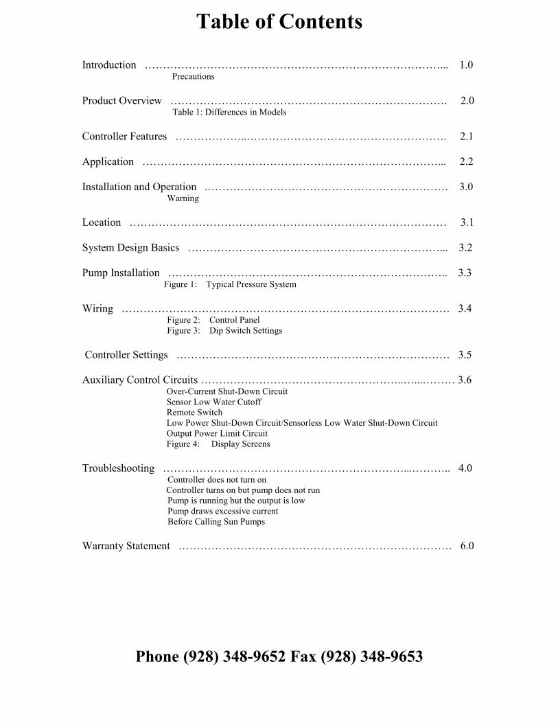
Table of Contents
Introduction ………………………………………………………………………... 1.0
Precautions
Product Overview …………………………………………………………………. 2.0 Table 1: Differences in Models
Controller Features ………………..………………………………………………. 2.1
Application ………………………………………………………………………... 2.2
Installation and Operation .………………………………………………………… 3.0 Warning
Location …………………………………………………………………………… 3.1
System Design Basics ……………………………………………………………... 3.2
Pump Installation ………………………………………………………………….. 3.3 Figure 1: Typical Pressure System
Wiring ……………………………………………………………………………… 3.4 Figure 2: Control Panel Figure 3: Dip Switch Settings
Controller Settings ………………………………………………………………… 3.5
Auxiliary Control Circuits ………………………………………………..…...……… 3.6 Over-Current Shut-Down Circuit
Sensor Low Water Cutoff
Remote Switch
Low Power Shut-Down Circuit/Sensorless Low Water Shut-Down Circuit
Output Power Limit Circuit
Figure 4: Display Screens
Troubleshooting …………………………………………………………...……….. 4.0 Controller does not turn on
Controller turns on but pump does not run
Pump is running but the output is low
Pump draws excessive current
Before Calling Sun Pumps
Warranty Statement ………………………………………………………………… 6.0
Phone (928) 348-9652 Fax (928) 348-9653
1.0 Introduction
Thank you for selecting a SunPumps SCB series solar pump system. The SCB series pump and PCC series
Sensorless Brushless DC - pump controller are the key components to high quality solar powered pumping
systems. Their stand-alone, pollution free and low noise operation makes them an ideal solution for remote
homes, irrigation projects, and wildlife and stock watering without violating the environment.
SunPumps SCB series pumps are multi-stage centrifugal, three phase DC powered, surface pumps
constructed of high quality stainless steel. These pumps were designed specifically for water delivery in
remote locations.
The PCC-BLS series controllers are microprocessor based solid state DC power converters designed as the
interface between a solar module array and a three phase sensorless brushless DC pump motor. The
purpose of the controller is to operate the high efficiency, high reliability DC motor and maximize the total
daily water output while providing protection for the pump as well as providing an interface with other
related pumping system equipment.
Although these SCB series pump systems are easy to install, please read this manual to become
familiar with the pump and controller features, functions, connection points and various
configurations. For future reference, keep this manual and other relevant product information in a
safe place.
PRECAUTIONS
• Safety First – Always understand what you are doing when working with any form of
electricity. Guessing at something is not worth the potential of product damage and/or
severe personal injury.
• Shut down all power when working on the system. Do not feed live wires into the PCC-BLS-
M2. Personal injury or other damage may result.
• Do not exceed the voltage rating of the controller.
• Do not run the pump dry.
• Do not splash water on the controller when the cover is open.
• Mount the controller in a shaded, well vented, vertical position.
• Installation of this system should be done by a licensed Pump Contractor.
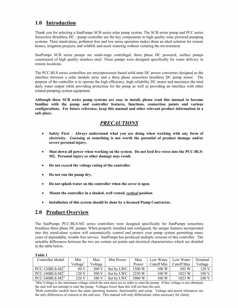
2.0 Product Overview
The SunPumps PCC-BLS-M2 series controllers were designed specifically for SunPumps sensorless
brushless three phase DC pumps. When properly installed and configured, the unique features incorporated
into this stand-alone system will automatically control and protect your pump system permitting many
years of dependable, trouble free service. SunPumps has produced multipls versions of this controller. The
noteable differences between the two are certain set points and electrical characteristics which are detailed
in the table below.
Table 1
Controller Model Min
Voltage1
Max
Voltage
Min Power Max
Power
Low Water
Cutoff Min
Low Water
Cutoff Max
Nominal
Voltage
PCC-120BLS-M22
90 V 200 V Set by LWC 1500 W 100 W 585 W 120 V
PCC-180BLS-M22
120 V 300 V Set by LWC 2250 W 100 W 1023 W 180 V
PCC-240BLS-M22 220 V 380 V Set by LWC 3000 W 100 W 1023 W 240 V
1Min Voltage is the minimum voltage which the unit must see in order to start the pump. If this voltage is not obtained,
the unit will not attempt to start the pump. Voltages lower than this will not hurt the unit. 2Both controller models have the same operating features, functionality and setup. Voltage and power tolerances are
the only differences of concern to the end user. This manual will only differentiate when necessary for clarity.
2.1 Controller Features
1. Current boosting for matching the load requirements of the pump.
2. Voltage regulation of the solar electric array at its maximum power point. (MPPT)
3. Over-current protection via integrated electronic circuit breaker.
4. Reverse polarity protection (10 amperes maximum) on the input terminals.
5. Voltage and current limiting to pump motor.
6. Transient protection and surge suppression.
7. Adjustable output motor power control for precision output flow.
8. Digital display indicating status, power, voltage, current and more.
9. System ON/OFF switch.
10. LED indicators; 1. Power In, 2. Motor Run, 3. MPPT, 4. RS Stop, 5. Low Power, 6. Over-
Current, 7. Fault Condition.
11. Weather resistant powder coated, die cast aluminum enclosure with a hinged door.
12. Rising clamp screw terminal blocks – no fork terminals required.
13. Pre-adjusted pump configuration and power source selection.
14. Remote switch interface – float switch or remote shutdown –Normally Open or Normally
Closed, user selectable.
15. Sensorless “Low Water” circuit
16. Low Power Shut Down circuit
2.2 Application
The only application the PCC series controllers are designed for is the interface between a solar module
array and SunPumps Sensorless Brushless DC motors.
No other applications or DC power sources are recommended or warranted unless written
approval is provided by the SunPumps factory.
3.0 Installation and Operation The following sections are outlined in a step-by-step format to guide you through the installation and
configuration of an SCB series pump and PCC series controller. The procedure for installing the SCB
submersible pump is the same as a standard AC submersible pump. Any licensed pump contractor will be
familiar with the proper installation procedures. The installation and operation should be in accordance
with local regulations, accepted codes of good practice and common sense. This pump should be installed
by a licensed professional pump installer.
Before installing any pump system read all product manuals then review all system components to
become familiar with the physical and electrical layout. Check all equipment for any product damage.
Refer to applicable figure(s) as a guide during the installation. Controller door must be closed during
normal operation.
Warning
Reverse polarity on a panel system capable of producing over 10 amps will result in
non-warranted product damage. Please check polarity before connecting power to the
controller.
This controller is for SunPumps Sensorless Brushless DC Motors only. Do not use this
controller on AC, Brush-Type or Sensor Type Brushless DC motors. Damage to the
controller and/or motor will result.
3.1 Location

As the majority of system installations vary greatly, only general comments can be made as to location.
Prior to installing the system, it is suggested to make a system layout plan. During the system layout, take
into consideration any potential shading of the solar electric modules, wire runs, wire size, conduit runs,
trenching, controller accessibility, tank location, pump head etc. Shading even a small portion of the array
can reduce the output of the entire array and thus reduce or completely stop the output of the pump. There
is no substitute for a good plan!
The PCC-series controller can either be mounted indoors or outdoors. Locate all system equipment as
close as possible to each other. For top of pole mount racks, the controller is usually mounted on the north
side (shaded side) of the mounting pole. The controller must be mounted in a vertical position for proper
cooling and to keep the electronics dry. The pole should be located close to the well (bore hole). This
general physical layout is conducive to clean installation both aesthetically and electrically.
3.2 System Design Basics (Read carefully before installation)
1. The pump discharge piping should be sized for efficient pump operation. We suggest using the
Friction Loss Tables to calculate the Total Dynamic Head using different pipe sizes. As a rule of
thumb use 1” for up to 8 GPM, 1 ¼” for up to 25 GPM, 1 ½” for up to 40 GPM and 2” for up to
70 GPM.
2. For optimum pump performance make sure that the wire is sized properly for the length of run
between the pump and the solar modules. Wire sized too small will cause a decreased output
from the pump. Keep the distance from the solar modules to the pump as short as possible.
Refer to a DC wire loss chart for proper sizing. It is recommended to keep the voltage drop
under 3%.
3. The SCB series booster pumps do not have good suction lift capabilities and it is recommended
to always have a positive suction head if possible. (Water above the inlet of the pump.) If this is
not possible then keep the suction lift to a minimum, no more than three feet.
4. Always use a foot valve on the suction hose with a negative suction lift. Keep the suction hose
in a straight sloping line without any loops where air could be trapped. Keep the suction hose as
short as possible.
5. Always fill the suction hose and the pump with water before you turn the pump on. If the pump
is operated dry, damage to the impellers will occur and dry running is not covered under
warranty.
6. If pumping from a tank or any source that could run low on water, install a low water float
switch to protect the pump from running dry.
7. If a pressure switch is used in the system, choose one with a Low Pressure Cut-Off. If the pump
runs dry the pressure will drop and the low pressure switch will turn the pump off.
8. Never install the controller in direct sunlight. Direct sunlight on the controller may cause over-
heating of the controller.
9. Never lay the controller on the ground or mount the controller in a horizontal position. The
controller should be mounted in a vertical position only. A convenient place to mount the
controller is on the north side (shaded side) of the solar module array.
10. The controller should be grounded to the pump motor housing, the frame of the solar modules
and to an 8-foot ground rod. If the well casing is steel it may be used as the ground rod. Drill
and tap a hole in the casing or weld a bolt to the casing for the ground lug. Use only a copper
lug to attach the ground wire. The cemented support structure pole will not provide an adequate
ground. Do not ground the positive or negative electrical wires. Always use a DC
surge/lightning arrestor on the panel side of the controller. (Midnight Solar MN-SPD surge
arrestor is recommended)
11. Do not ground the array positive or negative electrical wires.
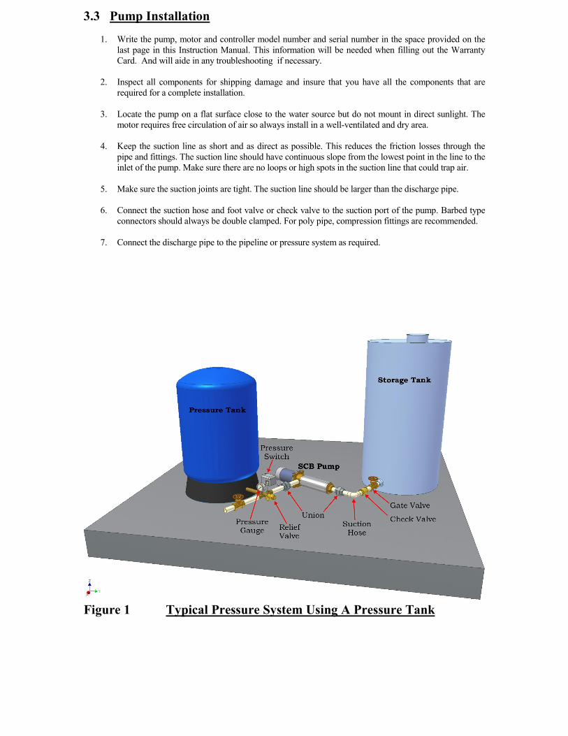
3.3 Pump Installation
1. Write the pump, motor and controller model number and serial number in the space provided on the
last page in this Instruction Manual. This information will be needed when filling out the Warranty
Card. And will aide in any troubleshooting if necessary.
2. Inspect all components for shipping damage and insure that you have all the components that are
required for a complete installation.
3. Locate the pump on a flat surface close to the water source but do not mount in direct sunlight. The
motor requires free circulation of air so always install in a well-ventilated and dry area.
4. Keep the suction line as short and as direct as possible. This reduces the friction losses through the
pipe and fittings. The suction line should have continuous slope from the lowest point in the line to the
inlet of the pump. Make sure there are no loops or high spots in the suction line that could trap air.
5. Make sure the suction joints are tight. The suction line should be larger than the discharge pipe.
6. Connect the suction hose and foot valve or check valve to the suction port of the pump. Barbed type
connectors should always be double clamped. For poly pipe, compression fittings are recommended.
7. Connect the discharge pipe to the pipeline or pressure system as required.
Figure 1 Typical Pressure System Using A Pressure Tank

3.4 Wiring
Prior to connecting any wires to the controller, be sure you have a system wiring diagram to use as a reference
(see figure 2). Guessing at polarity and connection points is not worth the risk of potential product damage
and/or personal injury.
Ensure the wire sizes are of adequate diameter (gauge) to minimize voltage drop. Please refer to a DC voltage
loss table or call your SunPumps dealer for assistance. Wire gauge being too small will cause excessive voltage
losses to the motor and will reduce the flow rate of the pump.
All other system equipment should be installed before proceeding with wiring the controller. Double check
polarity and wire termination tightness before powering up the system.
CAUTION: Photovoltaic panels produce DC electricity when exposed to sunlight. Cover the panels with
a blanket or with a non-opaque material before wiring. Install a disconnect switch between the solar
modules and the controller.
1. After mounting the controller, switch the controller to the OFF position.
2. If you are using a remote switch, like a float switch, set dip switch 1 to the correct position for the type of
switch being used. (“Normally Open” or “Normally Closed”.) If you are not using a remote switch leave
switch 1 off.
3. Verify all remaining dip switches are off at this time.
4. Connect ground rod conductor to the controller chassis ground block.
5. Connect solar module frame ground conductor to controller chassis ground block.
6. Connect the green pump ground conductor to controller chassis ground block.
7. Connect pump motor leads to the corresponding “Pump Motor” terminals on the controller. Red to “Red”,
yellow to “Yellow” and black to “Black”.
8. Verify that the disconnect switch is in the off position. Connect the DC source supply negative (-), the
black conductor, to one of the controller terminals labeled “Negative” on the “Solar Array Input”. (NOTE:
The power should be connected to a disconnect and it should be in the OFF position before connecting
power to the controller).
9. Connect the DC source supply positive (+), the red conductor, to one of the controller terminals labeled
“Positive” on the “Solar Array Input”. (NOTE: The power should be connected to a disconnect and it
should be in the OFF position before connecting power to the controller).
10. Refer to the next section for “Remote Switch” connections and “Adjustment Procedures” for
configuration, if applicable. Sensor type low water cutoff is supported by the controller but not for booster
pumps at this time. If you would like to use one contact Sunpumps for assistance.
11. At this point, all system components are installed and wired, double check conductor polarities, wire
termination tightness and controller configuration. With a DC volt meter check the array open circuit
voltage (Voc) on the array side of the disconnect switch and the module polarity. Record the Voc for
future reference. You may do this on the Before Calling Sun Pumps Worksheet near the end of this
manual. Check this voltage reading against the “Voc” range for your specific system in the chart below.
(Figure 3)
12. After you have verified the voltage and polarity, switch the disconnect switch on - if the polarity is correct
the first LED light will be on.
13. Turn the “On/Off “switch to the ON position. The system should be operational. If the system does not
start and turns on any error lights or gives you an error message, proceed to the troubleshooting guide.
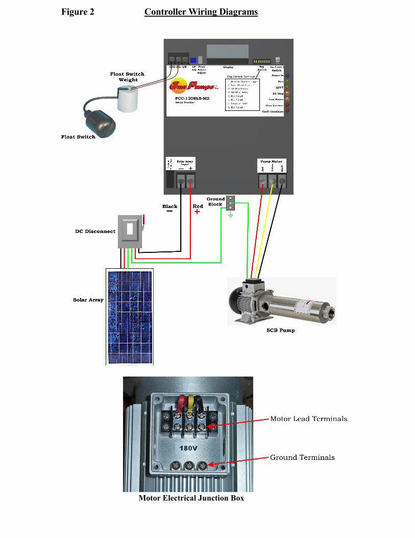
Figure 2 Controller Wiring Diagrams
Motor Electrical Junction Box

Figure 3 Dip Switch Settings
Switch Switch Description Function
Default
Setting Number Position
1 OFF Remote Switch Logic Turns pump off when terminals
connect. OFF
1 ON Remote Switch Logic Turns Pump on when terminals
connect. OFF
2 OFF Low Water Cutoff Logic Turns pump off when terminals
connect. OFF
2 ON Low Water Cutoff Logic Turns pump on when terminals
connect. OFF
3 ON 10 Minute Delay Increases turn on delay to 10
minutes OFF
4 ON 30 Minute Delay Increases turn on delay to 30
minutes OFF
5,6 Not used at this time Should be in the off position for
proper operation OFF
7 ON Display Freeze Holds display on current screen OFF
8 Not used at this time Should be in the off position for
proper operation OFF

3.5 Controller Settings
The PCC series controllers have several settings (see figure 3). Most features include system configuration
adjustments, some of which are user selectable by an eight position DIP-switch located on the face of the
controller.
Switch 1 is the Remote Switch Logic. With this switch off (down), terminals “RS+” and “GND” must be
connected to turn the controller off. With this switch on (up), terminals “RS+” and “GND” must be
connected to turn the controller on.
Switch 2 is the Low Water Cutoff Logic. With this switch off (down), terminals “RS+” and “GND” must
be connected to turn the controller off. With this switch on (up), terminals “RS+” and “GND” must be
connected to turn the controller on. If you want to use this feature with the booster pump system, contact
SunPumps for further assistance.
Switches 3 and 4 are delay timer adjustments. The delay timer is used for the remote switch and the low
water cutoff. This timer by default is set for one minute. Switch 3 will increase the timer to 10 minutes;
Switch 4 will increase it to 30 minutes. See Remote Switch and Low Water Cutoff for more information.
Switch 7 is used to control the user interface. When switch 7 is down, the LCD will display various
screens conveying pump and controller operating parameters. The display will cycle through each screen
at a predetermined rate. For troubleshooting and some setup features certain screens are desired. By
turning the switch number 7 on, the display will stop cycling and the current screen will stay on the display.
Switches 5, 6, and 8 are not used at this time and should remain down.
3.6 Auxiliary Control Circuits
The auxiliary control circuits are configured and controlled with the “Dip Switches”, “LP Adj.”, “Speed
Control” and the “RS”, “LW” and “GND” terminals. (See Figure 3)
These circuits offer expanded capability and are described here. The remote switch control is for float
switches (storage tank level), pressure switches or a remote system “ON/OFF” toggle switch. The motor
speed control is for adjusting the flow rate of the pump. There is also the low water cutoff, low power shut
down and over current protection circuits. See each corresponding detailed description below.
NOTE: Use only “Shielded Wire” to run from the remote switch to the controller and the ground
wire must be grounded to the controller side only. Induced voltages from lightning storms or two-way
radio transmissions could damage the controller.
Over-Current Shut Down Circuit
The over-current shut down circuit will turn the controller off any time the current exceeds the current limit
of the controller. When it turns the controller off it will remain off for 3 minutes and then turn on again.
When it turns off an error light will light and the display will say Over-Current. When it turns on again, if it
is still pulling excessive current it will continue to shut down for 3 minutes and try to restart.
Sensor Low Water Cutoff Circuit
The sensor type low water cutoff circuit is designed as a safety feature to protect your pump from running
dry or your tank from over flowing. This feature is designed for use in the submersible SCS systems with
the ground wire installed. For use with the SCB or SCP systems contact SunPumps for assistance. The
“LW” terminal of the controller should be attached to a low water sensor electrode which is mounted in
your tank or well. The system can be used to detect low water or to detect high water depending on the
position of switch 2 on the dip switch. When dip switch 2 is in the off position, the low water cutoff circuit
expects not to touch water. If water comes into contact with it, and completes the circuit to ground, the
pump will shut off until the water is removed and the delay timer times out. A three minute timeout is
default for this feature but is modifiable by switches 3 and 4 to 10 or 30 minutes respectively. This timeout
applies to remote switch and low water cutoff.

Remote Switch
The Remote Switch interface can serve as an automatic system shutdown when used with a water storage
tank mounted float switch, a pressure switch or it can also serve as a manual system shutdown with a
remote system ON/OFF toggle switch. The remote logic circuit allows the use of standard “Pump-Up or
Pump Down” float switches. Please refer to the following operation scenarios for configuration options.
With switch number 1 in the OFF position, the controller is configured to accommodate a Normally Open
(N.O.) float switch or remote toggle switch. In this configuration the controller will operate as follows:
PUMP ON
float switch open = water tank low = pump ON
PUMP OFF
float switch closed = water tank high = pump OFF
With switch number 1 in the ON position, the controller is configured to accommodate a Normally Closed
(N.C.) float switch, pressure switch or remote toggle switch. In this configuration the controller will
operate as follows:
PUMP ON
switch closed = water tank low = pump ON
PUMP OFF
switch open = water tank high = pump OFF
A one minute minimum timeout is default for this feature but is modifiable by switches 3 and 4 to 10 or 30
minutes respectively. At certain times the controller may be off for up to 14 minutes depending on various
factors in the controller program. This timeout applies to remote switch and low water cutoff.
Low-Power Shut-Down/Sensorless Low Water Cut-Off Circuit (LPLW)
The Low-Power Shut-Down/ Low Water Cut-Off Circuit (LPLW) turns the pump off any time the
controller output power drops below a functional level. This may be caused by lack of power from the solar
panels or from running out of water. This protects the pump in stall conditions and saves wear on the
system when no or very little water is being pumped. This feature must be adjusted for your specific
application.
This feature is always monitoring the output of the motor. If you are not interested in using this feature
turn the “LP Adj” trim pot fully counter-clockwise. This will give the pump the minimum low power set
point possible.
LPLW Adjustment The Low Water Cut-Off Circuit and the Low Power Shut-Down circuit are adjusted using the same trim pot
labeled “LP Adj.” on the controller. The default is the arrow pointing straight up. This is sufficient for
most systems but adjustment will maximize the life and output of your system. Follow the steps below to
adjust this feature.
1. Turn the “LP Adj.” trim pot fully counter clockwise.
2. Turn the “Speed Control” trim pot counter clockwise until the pump is pumping the desired
minimum flow. This may be down to 0 gal/min but is not recommended for proper pump cooling.
3. Turn the “LP Adj.” trim pot clockwise until the pump shuts off.
4. Reset the “Speed Control” trim pot back to the desired position.
Output Power Limit Circuit (Motor Speed Control)
The Output Power Limit Control circuit is used to control the speed of the pump motor and thus the flow
rate of the pump. It is primarily used for low producing wells where the pump output is matched to the
production rate of the well. However it can also be used any time specific flow rates are required.
Output Power Limit Adjustment The purpose of this procedure is to adjust the output power of the controller and thus reduce the water flow
of the pump. If tests have shown the pump will out produce the well capacity, then the controller “Speed
Control” feature can be used to match the flow rate of the pump to the production of the well.
1. With the system installed and controller properly configured, allow the pump to run at full power at
mid-day until the pump starts surging.
2. Slowly turn the “Speed Control” trim pot located on the face of the controller counter clockwise until
the pump stops surging. This is the point where the pump flow rate equals the well production. This
process will probably take a few attempts to “balance” the system for optimum water production. If
maximum water is not a critical issue you may want to reduce the pumps flow rate an additional 5% to
10% to insure the pump will not run dry.
(NOTE: The trim pot has a15- turn range. It usually takes many complete turns in a counter-clockwise
direction before you will notice any change in water output or output power on the display).

Figure 4 Display Screens
NOTE: Dip switch 7 will freeze the display on the current screen. If the system is
powered up with switch 7 on, the display will only show the SUNPUMPS, INC
screen. Turn off switch 7 to unfreeze the display.
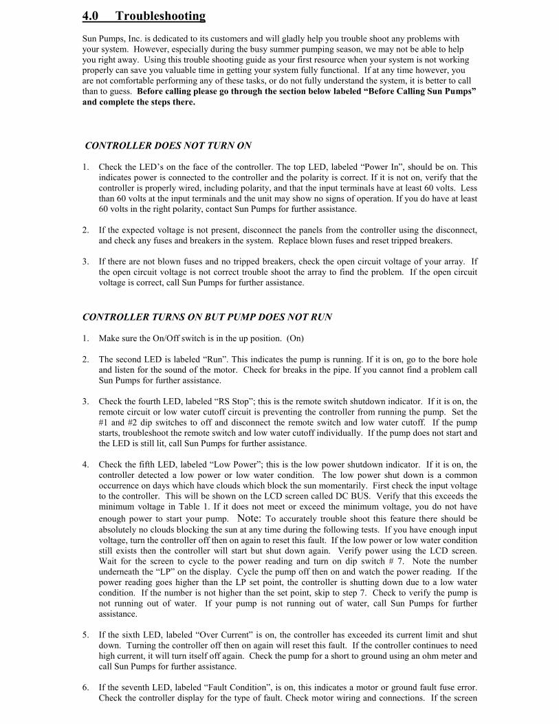
4.0 Troubleshooting
Sun Pumps, Inc. is dedicated to its customers and will gladly help you trouble shoot any problems with
your system. However, especially during the busy summer pumping season, we may not be able to help
you right away. Using this trouble shooting guide as your first resource when your system is not working
properly can save you valuable time in getting your system fully functional. If at any time however, you
are not comfortable performing any of these tasks, or do not fully understand the system, it is better to call
than to guess. Before calling please go through the section below labeled “Before Calling Sun Pumps”
and complete the steps there.
CONTROLLER DOES NOT TURN ON
1. Check the LED’s on the face of the controller. The top LED, labeled “Power In”, should be on. This
indicates power is connected to the controller and the polarity is correct. If it is not on, verify that the
controller is properly wired, including polarity, and that the input terminals have at least 60 volts. Less
than 60 volts at the input terminals and the unit may show no signs of operation. If you do have at least
60 volts in the right polarity, contact Sun Pumps for further assistance.
2. If the expected voltage is not present, disconnect the panels from the controller using the disconnect,
and check any fuses and breakers in the system. Replace blown fuses and reset tripped breakers.
3. If there are not blown fuses and no tripped breakers, check the open circuit voltage of your array. If
the open circuit voltage is not correct trouble shoot the array to find the problem. If the open circuit
voltage is correct, call Sun Pumps for further assistance.
CONTROLLER TURNS ON BUT PUMP DOES NOT RUN
1. Make sure the On/Off switch is in the up position. (On)
2. The second LED is labeled “Run”. This indicates the pump is running. If it is on, go to the bore hole
and listen for the sound of the motor. Check for breaks in the pipe. If you cannot find a problem call
Sun Pumps for further assistance.
3. Check the fourth LED, labeled “RS Stop”; this is the remote switch shutdown indicator. If it is on, the
remote circuit or low water cutoff circuit is preventing the controller from running the pump. Set the
#1 and #2 dip switches to off and disconnect the remote switch and low water cutoff. If the pump
starts, troubleshoot the remote switch and low water cutoff individually. If the pump does not start and
the LED is still lit, call Sun Pumps for further assistance.
4. Check the fifth LED, labeled “Low Power”; this is the low power shutdown indicator. If it is on, the
controller detected a low power or low water condition. The low power shut down is a common
occurrence on days which have clouds which block the sun momentarily. First check the input voltage
to the controller. This will be shown on the LCD screen called DC BUS. Verify that this exceeds the
minimum voltage in Table 1. If it does not meet or exceed the minimum voltage, you do not have
enough power to start your pump. Note: To accurately trouble shoot this feature there should be absolutely no clouds blocking the sun at any time during the following tests. If you have enough input
voltage, turn the controller off then on again to reset this fault. If the low power or low water condition
still exists then the controller will start but shut down again. Verify power using the LCD screen.
Wait for the screen to cycle to the power reading and turn on dip switch # 7. Note the number
underneath the “LP” on the display. Cycle the pump off then on and watch the power reading. If the
power reading goes higher than the LP set point, the controller is shutting down due to a low water
condition. If the number is not higher than the set point, skip to step 7. Check to verify the pump is
not running out of water. If your pump is not running out of water, call Sun Pumps for further
assistance.
5. If the sixth LED, labeled “Over Current” is on, the controller has exceeded its current limit and shut
down. Turning the controller off then on again will reset this fault. If the controller continues to need
high current, it will turn itself off again. Check the pump for a short to ground using an ohm meter and
call Sun Pumps for further assistance.
6. If the seventh LED, labeled “Fault Condition”, is on, this indicates a motor or ground fault fuse error.
Check the controller display for the type of fault. Check motor wiring and connections. If the screen

displays “GF FUSE OPEN” the ground fault fuse has been blown. Check your system for ground
loops and replace the fuse with a 500 VDC 1A rated fuse. If this does not solve the issue, contact Sun
Pumps for further assistance.
7. Check for proper dip switch settings on your controller. Switches 5, 6, and 8 must be in the off position
for proper operation.
8. Check for proper controller input voltage. A quick look at the controller display will verify the array
voltage. If the pump is not running the display should be reading the array open circuit voltage, (Voc).
Verify that this voltage is below the maximum input voltage allowed for your controller (Model
Dependent See Table 1). Check the Voc on the label on the back of the solar modules and multiply
this figure times the number of modules that are connected in series. This number should be + - 10% of
the display reading. If it is not then confirm all electrical terminations are tight and secure. Use a DC
volt meter to check each solar module for proper open circuit voltage (Voc). One bad module will drop
the voltage on the complete series string.
PUMP IS RUNNING BUT THE OUTPUT IS LOW
1. Make sure you have full sun light at midday, that there are no clouds and no shadows on any part of
the array. Then verify power coming out of the controller. Look at the LCD screen and read the
voltage, current and power. Check this against the pump chart for your specific application.
2. If the power is correct for your pump model and array size then make sure the pump wires are
connected to the proper terminals. If two wires are reversed the motor will be running in reverse. It
may still pump but not at the full rated output.
3. If the wires are correct verify that your system does not have any leaks where water can be lost. If you cannot determine the problem, contact Sun Pumps for further assistance.
PUMP DRAWS EXCESSIVE CURRENT (More than the rating of the pump, but less than the
rating of the controller)
1. Check wiring diagram for proper connection.
2. Check for skinned wires or faulty underwater splice.
3. Check for locked motor armature. With the pump out of the well, remove the pump end from the
motor (if this is not feasible skip this step and contact Sun Pumps). Allow the controller to attempt to
start the motor. If the motor still does not run. Contact the Sun Pumps for further assistance.

BEFORE CALLING SUNPUMPS
If at all possible when calling Sun Pumps for technical support there are a few things which will help to
speed up the process and help us determine the cause of and solution to the system failure. The best way to
get help is to call while you are physically at the location of your pump, have good sunlight, and have a
multimeter and a screwdriver with you.
Furthermore, please fill out the form below before calling. This information will provide us with most of
the preliminary information we need to help you. If you cannot physically be at the site, filling out the
worksheet is a must.
Pump Model Number: ____________________
Pump Serial Number: ____________________
Motor Serial Number: ____________________
Controller Model Number: ____________________
Software Version ____________________
Date Purchased: ____________________
Solar Module Specifications:
Model Number ____________________
Rated Watts ____________________
Voc ____________________
Vmp ____________________
Isc ____________________
Imp ____________________
Solar Modules Connected in Series _______________ X Voc _______ = _________ Array Voc
Solar Modules Connected in Series _______________ X Vmp _______ = _________ Array Vmp
Series Strings Connected in Parallel_______________ X Isc _________= _________ Array Isc
Series Strings Connected in Parallel_______________ X Imp _________= _________ Array Imp
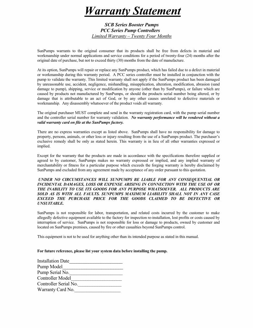
Warranty Statement
SCB Series Booster Pumps
PCC Series Pump Controllers
Limited Warranty – Twenty Four Months
SunPumps warrants to the original consumer that its products shall be free from defects in material and
workmanship under normal applications and service conditions for a period of twenty-four (24) months after the
original date of purchase, but not to exceed thirty (30) months from the date of manufacture.
At its option, SunPumps will repair or replace any SunPumps product, which has failed due to a defect in material
or workmanship during this warranty period. A PCC series controller must be installed in conjunction with the
pump to validate the warranty. This limited warranty shall not apply if the SunPumps product has been damaged
by unreasonable use, accident, negligence, mishandling, misapplication, alteration, modification, abrasion (sand
damage to pump), shipping, service or modification by anyone (other than by SunPumps), or failure which are
caused by products not manufactured by SunPumps, or should the products serial number being altered, or by
damage that is attributable to an act of God, or by any other causes unrelated to defective materials or
workmanship. Any disassembly whatsoever of the product voids all warranty.
The original purchaser MUST complete and send in the warranty registration card, with the pump serial number
and the controller serial number for warranty validation. No warranty performance will be rendered without a
valid warranty card on file at the SunPumps factory.
There are no express warranties except as listed above. SunPumps shall have no responsibility for damage to
property, persons, animals, or other loss or injury resulting from the use of a SunPumps product. The purchaser’s
exclusive remedy shall be only as stated herein. This warranty is in lieu of all other warranties expressed or
implied.
Except for the warranty that the products are made in accordance with the specifications therefore supplied or
agreed to by customer, SunPumps makes no warranty expressed or implied, and any implied warranty of
merchantability or fitness for a particular purpose which exceeds the forging warranty is hereby disclaimed by
SunPumps and excluded from any agreement made by acceptance of any order pursuant to this quotation.
UNDER NO CIRCUMSTANCES WILL SUNPUMPS BE LIABLE FOR ANY CONSEQUENTIAL OR
INCIDENTAL DAMAGES, LOSS OR EXPENSE ARISING IN CONNECTION WITH THE USE OF OR
THE INABILITY TO USE ITS GOODS FOR ANY PURPOSE WHATSOEVER. ALL PRODUCTS ARE
SOLD AS IS WITH ALL FAULTS. SUNPUMPS MAXIMUM LIABILITY SHALL NOT IN ANY CASE
EXCEED THE PURCHASE PRICE FOR THE GOODS CLAIMED TO BE DEFECTIVE OR
UNSUITABLE.
SunPumps is not responsible for labor, transportation, and related costs incurred by the customer to make
allegedly defective equipment available to the factory for inspection re-installation, lost profits or costs caused by
interruption of service. SunPumps is not responsible for loss or damage to products, owned by customer and
located on SunPumps premises, caused by fire or other casualties beyond SunPumps control.
This equipment is not to be used for anything other than its intended purpose as stated in this manual.
For future reference, please list your system data before installing the pump.
Installation Date______________________
Pump Model_________________________
Pump Serial No.______________________
Controller Model_____________________
Controller Serial No.__________________
Warranty Card No.___________________