Survey Robot Using Satellite GPS - Semantic Scholarthree-dimensional survey of topography. It has...
8
/1uwiuauon anU KOnOUcs to t _. onstrucutm n G.H. Watson, R.L. Tucker and J.K. Walters (Editors) 0 1993 Elsevier Science Publishers B.`.'. 11 d!: Survey Robot Using Satellite GPS Tadashi Kanzaki, Shuiti Nishizawa, and Hiroshi Toida 479 Construction Technology Development Dept., Technology Div., Taisei Corporation, Sanken Bldg., 3-25-1 Hyakunin-cho-, Shinjuku-ku, Tokyo 169, Japan Abstract In Japan, many large projects have been undertaken such as the 513-hectare artificial island of Kansai International Airport and the about 1,000-hectare offshore development project of Haneda International Airport. In the case of civil engineering works involving such a wide area, it is important from the viewpoint of construction management that daily topographic survey be made quickly. GPS is an abbreviation for Global Positioning system, which measures the three dimensional coordinates by receiving microwaves from artificial satellites. By loading this receiver on a vehicle, the survey robot three-dimensionally measures the topography at 0.5 second intervals while the vehicle is running. This robot was used in the reclamation work of Kansai International Airport development project. It has accomplished the three-dimensional topographic survey at 4,000 points in an area of 20 ha in only two hours. One further application of this robot is unmanned surveying for golf courses. 1. INTRODUCTION Highly accurate measurement methods and advanced management techniques are a critical part of the quest to reduce construction period, labor requirements, energy usage, and cost of large projects, such as airports and land reclamation. This is true for all stages of the work. ranging from surveys and planning to actual execution of the work. For instance, at a large- scale land development site, a swift and simple method of surveying can play a significant role in estimating the amount of cut and fill required. Highly systemized management is needed to properly handle information about complex geological structures and various soils measured in surveys. At a large-scale site, such as an offshore airport or reclamation site, the soft ground is often boggy. yet settlement and ground behavior have to be managed through fill geometry measurements to obtain early estimates of any additional fill needed. Over such vast areas, where efficiency and precision are the determining factors of successful work. there is an urgent need for a survey system based on the satellite global positioning system (GPS). A means of integrating such a system into all fields of work management is also being demanded. This paper outlines part of our response to this need; a robot which can carry out rapid topographical surveys. Its application to the work now in progress at the Kansai International Airport is discussed, along with a brief mention of some other survey robots which may be of interest regarding future unmanned surveying.
Transcript of Survey Robot Using Satellite GPS - Semantic Scholarthree-dimensional survey of topography. It has...

/1uwiuauon anU KOnOUcs to t _.onstrucutm n
G.H. Watson, R.L. Tucker and J.K. Walters (Editors)
0 1993 Elsevier Science Publishers B.`.'. 11 d!:
Survey Robot Using Satellite GPS
Tadashi Kanzaki, Shuiti Nishizawa, and Hiroshi Toida
479
Construction Technology Development Dept., Technology Div., Taisei Corporation, SankenBldg., 3-25-1 Hyakunin-cho-, Shinjuku-ku, Tokyo 169, Japan
AbstractIn Japan, many large projects have been undertaken such as the 513-hectare artificial
island of Kansai International Airport and the about 1,000-hectare offshore developmentproject of Haneda International Airport. In the case of civil engineering works involvingsuch a wide area, it is important from the viewpoint of construction management that dailytopographic survey be made quickly. GPS is an abbreviation for Global Positioning system,which measures the three dimensional coordinates by receiving microwaves from artificialsatellites. By loading this receiver on a vehicle, the survey robot three-dimensionallymeasures the topography at 0.5 second intervals while the vehicle is running. This robot wasused in the reclamation work of Kansai International Airport development project. It hasaccomplished the three-dimensional topographic survey at 4,000 points in an area of 20 ha inonly two hours. One further application of this robot is unmanned surveying for golf courses.
1. INTRODUCTION
Highly accurate measurement methods and advanced management techniques are a criticalpart of the quest to reduce construction period, labor requirements, energy usage, and cost oflarge projects, such as airports and land reclamation. This is true for all stages of the work.ranging from surveys and planning to actual execution of the work. For instance, at a large-scale land development site, a swift and simple method of surveying can play a significantrole in estimating the amount of cut and fill required. Highly systemized management isneeded to properly handle information about complex geological structures and various soilsmeasured in surveys. At a large-scale site, such as an offshore airport or reclamation site, thesoft ground is often boggy. yet settlement and ground behavior have to be managed throughfill geometry measurements to obtain early estimates of any additional fill needed. Over suchvast areas, where efficiency and precision are the determining factors of successful work.there is an urgent need for a survey system based on the satellite global positioning system(GPS). A means of integrating such a system into all fields of work management is also
being demanded.This paper outlines part of our response to this need; a robot which can carry out rapid
topographical surveys. Its application to the work now in progress at the Kansai InternationalAirport is discussed, along with a brief mention of some other survey robots which may be ofinterest regarding future unmanned surveying.
480
2. GLOBAL POSITIONING SYSTEM (GPS)
The global positioning system (GPS) was set up by the U.S. Department of Defense. Theground position is established using a network of 24 satellites about 20,000 km from theearth on six different orbitals, four on each orbital, as shown in Fig. 1.
Two pseudo-microwave signals, called the Ll wave and L2 wave at frequencies of 1.5GHz and 1.2 GHz, respectively, are continually transmitted from the satellites. These signalscarry encoded data giving atomic clock information, ionosphere correction information, andinformation on the satellites' orbits. This information is coded in two ways: one exclusivelyfor military purposes and the other openly available to the public at no charge.
Figure 1. Artist's impression of the GPS satellites and their orbits
3. DYNAMIC GPS SURVEY TECHNIQUE
Conventional survey methods absorb considerable amounts of labor and time becauseoptical surveying equipment requires three to four operators and all analysis has to be donemanually. Other survey methods, including the Total Station (Electronic DistanceMeasurement, EDM) suffers from some constraints:
(1) the need for mutual visual contact between any two survey points:(2) significant dependence on expertise and experience: and(3) susceptibility to weather and other factors.
The GPS is currently in use by the Geographical Survey Institute of the Ministry ofConstruction, which has confirmed the locational accuracy of the system. They are nowusing it for precise re-mapping of triangulation stations in Japan, however, the static GPSsurvey methods generally used for reference point surveys take a few hours to measure asingle point. In contrast, at a large-scale earthworks site where work is rapidly implemented,topographical surveying of a large area must be completed within a very limited time. Forthis reason, the normal static GPS method is not considered suitable for earthworksapplications.
481
Th,; dynamic GPS survey technique proposed here, however, enables an instantaneousthree-dimensional survey of topography. It has been the subject of various discussions andtests related to survey time and accuracy, and has overcome the conventional restrictions ofboth software and hardware in this kind of technique. Our new method also reduces thenumber of survey operators from three or four to only one, and will eventually enable fast,continuous measurements.
GPS satellite
IonosphereTroposphere
Orbit
Receive-r1 1 Receiver 2
Phase information Phase informationI Numerical
Post-processing Processing,^r-
Base line data
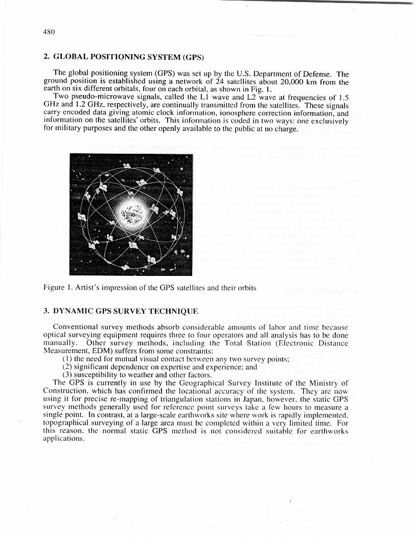
Figure 2. Conceptual outline of relativepositioning
[Satellite clock error
Receiver clock errror
Figure 3. Propagation distance andcauses of error
3.1 Principle of measurementFigure 2 illustrates the idea of relative positioning. This principle is encapsulated in the
equation below. p t and p2 are the distances from the satellite to receivers 1 and 2,respectively.
Pt-P2=Xs-Xt
Where: Xs: Position vector of the GPS satellite
Xt Position vector of the receiver I
X2 : Position vector of the receiver 2I I: Absolute value of vector
(1)
X, and X2 on the right hand side of Eq. 1 are unknown values with three components,
while X, is a known value with three components contained in the orbital information fromthe GPS satellite. If one of the two receivers is at a known point, the number of unknown
482
values is reduced to three. Since the left hand side is actual data from a satellite, data fromthree different satellites gives three versions of Eq. 1, each of which can be solved for threeunknown values. That is, a receiver in an unknown location can be positioned. However, thecollected data contains other information, including the phase difference between the signalreceived from the GPS satellite at two receivers. This phase difference results from thegeometrical relationship of position between the satellite and the two receivers, but it is also
influenced by propagation delays in the ionosphere and troposphere, delays within eachreceiver, and time differences. For this reason, the phase difference measured betweenreceivers I and 2 is considered an unknown which depends on the receivers themselves. To
obtain its actual value, data from another satellite are required. In practice, manyobservations are made to analyze and determine this unknown quantity.
3.2 Double-difference processing of carrier phasesThe normal accuracy of GPS is around 30 m because of the inability to eradicate errors
which are common to all observations,. Any practical application of GPS thus requires thedevelopment of a relative positioning system which can measure carrier phase at more thanone receiver. Under the double-difference processing system, signals are taken from four ormore GPS satellites to determine the absolute coordinates of a survey point.
The measurement errors can be mainly attributed to three effects:(1) clock errors in the satellite;(2) clock errors in the receiver; and(3) wave propagation delays in the ionosphere and atmosphere.
In Fig. 3, the following symbols are used:R: distance between satellite and receiver, along which signals propagaten: the number of wavelengthsX: wavelengthApt: residual phase
To eliminate errors, the following procedure is adopted: First, two receivers receive thecarrier phase from the same satellite and the phase difference is calculated. The samemeasurements are then made using another satellite; the difference in phase measurements isthen compared. This double-difference processing allows any errors to be eradicated.Assuming that the absolute phase difference between receiver I and 2 (distance from eachend of the baseline to the satellite) is Apt and AP2, respectively, the difference of positioning,6, the difference of the phase difference between the two satellites. E, is given by the
following equation:
=(nIx+ApI-(5)-(n2A+Ap2-6)=(nl-n2),1 + ApI - Ap2
This double-difference method of processing is essential to high-precision three-
dimensional positioning. The positioning data obtained by this method are converted into
Japanese geodetic coordinates from WGS-84.
3.3 Characteristics of dynamic GPS surveying(1) This method allows instantaneous and continuous three-dimensional positioning,
significantly improving work efficiency.(2) This method allows measurements to he made easily by a single person. A quick,
simultaneous multiple-point survey of a large area can be implemented by increasing thenumber of receivers.
483
(3) This method led to Japan 's first case of a continuous survey to I cm accuracy.
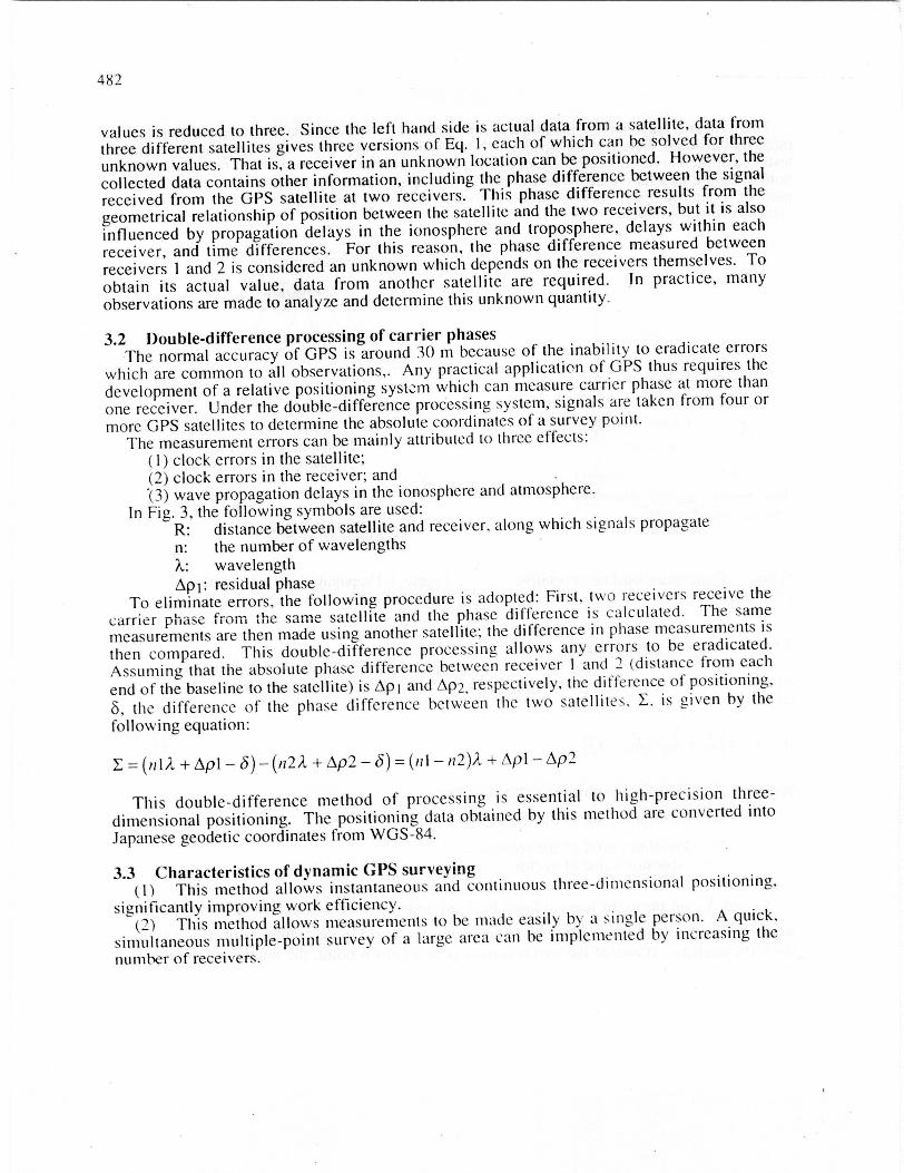
4. 3-D TOPOGRAPHIC SURVEY ROBOT
The 3-D topographic survey robot, shown in Fig. 4, is a development of GPS technologyfor use at an artificial island work site. As shown in Photo I, this robot is a vehicle equippedwith a receiving antenna; it carries out continuous topographic surveying while movingaround the site. It has performed well at an actual work site, demonstrating its efficiency andprecision.
Figure 4. Artist's impression of large-area Photo 1. Vehicle used for GPS high-speed3-D topographic surveying using vehicle dynamic positioning
4.1 High-accuracy positioning of dynamic platforms with GPSIn developing a vehicle to carry out highly accurate continuous positioning, a series of
tests was implemented to check the basic characteristics of the equipment. Variousexperiments were then conducted to solve several problems which manifested themselvesduring this development process.
One characteristic of this system is that only one piece of data is received for each surveypoint. If signals from the satellite are interrupted for any reason during the survey, errors inthe phase data may arise. Such errors, known as cycle slip, must be avoided. Therelationship between the velocity of the vehicle and survey accuracy also had to be clarified.The main issues considered in the study were (1) the optimum combination of satellites. (2)the initial setting (selection of a whole number bias), (3) the method of measuring the antennaheight, and (4) the optimum vehicle speed.
There are almost no obstacles to reception of GPS satellite transmissions at an airportconstruction site. but it must be considered that terrestrial refraction could affect high-accuracy positioning.
The refractive index (n) of air for frequencies less than 30 GHz is shown in Eq. 2:
484
n-1=j 0.776-+3.73x10³ z^xl0-6
Where P,e: atmospheric pressure and partial pressure of vapor expressed in Pa
(1 mbar = 102 Pa)T: temperature in K (0°C = 273K)
Differentiating Eq. 2 by the height , h, gives:
do=10_6- P• T 1 +3.73x10³^
1 de 2e dT
-( dh T dhdh T (T dh J
(2)
(3)
According to Eq. 3 and the formula for atmospheric density, readings from a satellite at anelevation of 15° or more are required to obtain locational accuracy of better than 1 cm.
Actual use of the new method at an airport construction site has clarified the following:(1) This method does not require the services of an expert surveyor to obtain the required
level of accuracy. Any lay operator can easily and quickly carry out survey work.(2) This method requires only a single operator for its operation, so it will eventually lead
to great savings in labor costs compared with conventional systems that require a group of at
least three to four surveyors.(3) This method allows a single operator to complete a survey of one hectare in five to six
minutes, a task which previously took a team of three to four surveyors an hour.
GPS Satellite
_1V_ :R MIAIOI
f v ;
(;PS receiveriverPS receG
Survey point
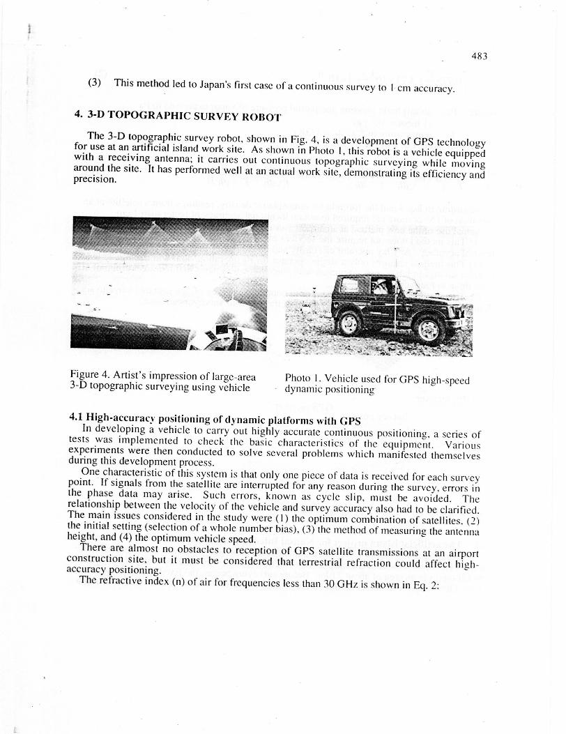
Figure 5. GPS high-speed 3-D topographic survey
4.2 The artificial island project for Kansai International AirportThe high-speed dynamic surveying method described in this paper was put to practical use
at the 1 1th work section of this airport construction site. It was used to survey the height ofthe fill top over an area of about 21 ha. Before surveying began, the fixed and moving pointsof the GPS receiver were set at known coordinates. Transmissions were received for a few
485
minutes to determine the number of carrier phases. Then , as shown in Fig. 5, the roving
receiver was placed on the roof of a vehicle, which was subsequently driven over unknownpoints and data taken continuously at intervals of 0.5 to 2.0 seconds.
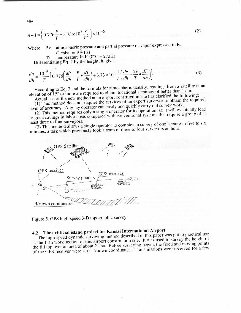
A total of 5,200 and 1,300 points, respectively, were recorded on the fill top (about 21 ha)and loaded fill (about 9 ha) in a total period of about 3 hours, as shown in Fig. 6. This workat Kansai International Airport quantitatively proved the energy and labor saving effects ofthis newly developed high-speed dynamic positioning method.
The main features of this new method are summarized below.(1) A high degree of accuracy, to about 15 mm, is possible, as confirmed in the precision
experiments, regardless of the velocity of the vehicle.(2) The method is especially effective in the planar surveying of a large area.(3) A single operator is able to complete the topographic surveying of a vast area of land.(4) The reception interval can be freely chosen according to the purpose of the survey.(5) Computer processing enables continuous output of analyzed data and coordinates.
Figure 6. Tracks of survey points (Kansai International Airport: 1,350 x 420 m)
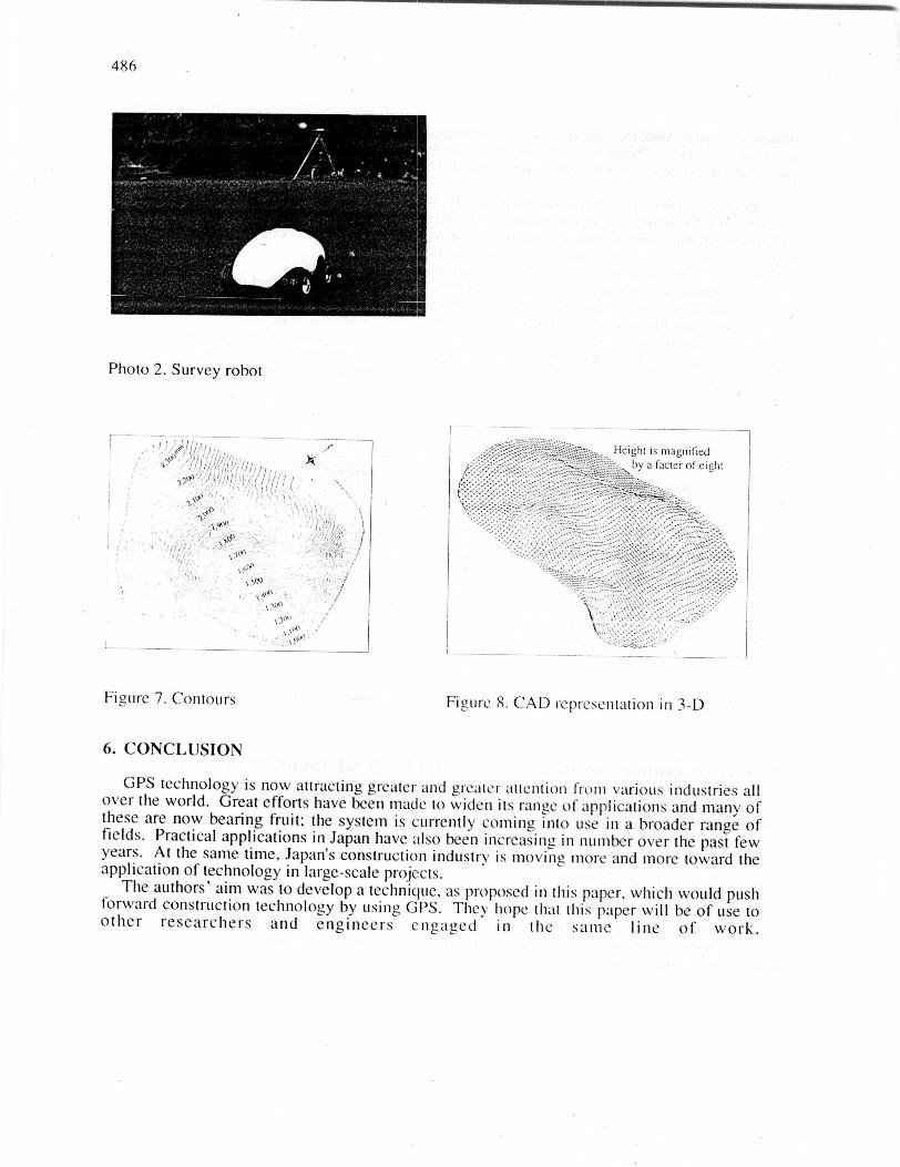
5. SURVEY ROBOT FOR GOLF GREEN CONTOUR MEASUREMENT
A high-accuracy, continuous surveying system using a remote-controlled vehicle, asshown in Photo 2, was used to survey the contours of a golf green. The work entailedequipping a remote control vehicle with a GPS receiving antenna and carrying out acontinuous three-dimensional topographical survey of the greens. The system was put into
practice at an actual golf course.This survey enabled contours and bird's-eye views of the golf course to be produced, as
shown in Figs. 7 and 8.This survey robot will enable a data base of well-known golf courses to be created, even
allowing them to he duplicated. This function will make it easy to repair existing greens or
recover their original form.
486
Photo 2. Survey robot
Height is magnifiedby a factor of eight
Figure 7. Contours
6. CONCLUSION
Figure S. CAD representation in 3-D
GPS technology is now attracting greater and greater attention Irvin various industries allover the world. Great efforts have been made to widen its range of applications and many ofthese are now hearing fruit; the system is currently coming into use in a broader range offields. Practical applications in Japan have also been increasing, in number over the past fewyears. At the same time, Japans Construction industry is moving more and more toward theapplication of technology in large-scale projects.
The authors' aim was to develop a technique, as proposed in this paper, which would pushforward construction technology by using GPS. They hope that this paper will he of use toother researchers and engineers engaged in the same line of work.


![Impact of transient CSMA/CA access delays on Active ...personals.ac.upc.edu/acabello/PDF/[acabello]Impact of transient CSMACA... · Impact of transient CSMA/CA access delays on Active](https://static.fdocument.pub/doc/165x107/5e66cbdb1d388c75ce0022de/impact-of-transient-csmaca-access-delays-on-active-acabelloimpact-of-transient.jpg)