Study on the Improvement of the Serviceability...
69
Study on the Improvement of the Serviceability Performance of Earth Hydraulic Structures by using High Performance Fiber Reinforced Cementitious Composites 複数微細ひび割れ型繊維補強セメント複合材料による土構造水利施設の使用性の向上に関する研究 PANGANAYI CLEOPATRA 2011 Study on the Improvement of the Serviceability Performance of Earth Hydraulic Structures by using High Performance Fiber Reinforced Cementitious Composites
Transcript of Study on the Improvement of the Serviceability...
Study on the Improvement of the Serviceability Performance
of Earth Hydraulic Structures by using High Performance
Fiber Reinforced Cementitious Composites
複数微細ひび割れ型繊維補強セメント複合材料による土構造水利施設の使用性の向上に関する研究
PANGANAYI CLEOPATRA
2011
Study on the Improvement of the Serviceability Performance of Earth Hydraulic Structures by using High Performance Fiber Reinforced Cementitious
Composites

By
PANGANAYI CLEOPATRA
June 2011
A thesis submitted in partial fulfillment of the requirement of Doctor of
Philosophy Degree
in
Water Supply Engineering
Water Supply Facilities Laboratory Production Environmental Engineering Division
Tottori University Japan

Supervisors
Dr. Hidehiko Ogata
(Major Supervisor)
Associate Professor, Water Supply Facilities Laboratory, Tottori University
Dr. Kunio Hattori
(Second Supervisor): 2008.10.1 -2011.3.30
Professor, Water Supply Facilities Laboratory, Tottori University
Dr. Yoshinobu Kitamura
(Second Supervisor): 2011.4.1 -2011.9.30
Professor, Water Use and Management Laboratory, Tottori University
Dr. Masayuki Ishii
(Third Supervisor)
Associate Professor, Structural Material Engineering Laboratory, Shimane University
Examining Committee
Dr.Hidehiko Ogata - Associate Professor, Water Supply Facilities Engineering, Tottori University
Dr.Yoshinobu Kitamura- Professor, Water Use and Management, Tottori University
Dr.Koji Inosako – Associate Professor, Soil and Water Management, Tottori University
Dr.Tsuguhiro Nonaka- Professor, Structural Material Engineering, Shimane University
Dr.Ichiro Kita – Professor, Water and Vegetation Use Planning, Shimane University
Acknowledgements

I would like to express my profound gratitude to my supervisor, Dr Hidehiko Ogata for his commitment and
guidance throughout this course. I benefited immensely from his ingenuity. Special thanks go to Professor Kunio
Hattori for his encouragement and priceless wisdom. Many thanks also go to Dr Masayuki Ishii for his contributions
and my laboratory colleagues for their assistance during my experiments. To my husband, Teckshaw, I cherish your
patience and support. Finally I would like to thank my family for always believing in me and to God Almighty,
through whom all things are possible, be all the glory.
Abstract
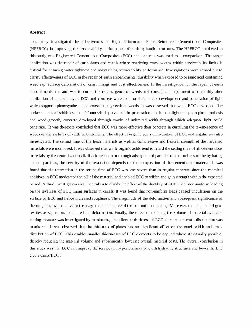
This study investigated the effectiveness of High Performance Fiber Reinforced Cementitious Composites
(HPFRCC) in improving the serviceability performance of earth hydraulic structures. The HPFRCC employed in
this study was Engineered Cementitious Composites (ECC) and concrete was used as a comparison. The target
application was the repair of earth dams and canals where restricting crack widths within serviceability limits is
critical for ensuring water tightness and maintaining serviceability performance. Investigations were carried out to
clarify effectiveness of ECC in the repair of earth embankments, durability when exposed to organic acid containing
weed sap, surface deformation of canal linings and cost effectiveness. In the investigation for the repair of earth
embankments, the aim was to curtail the re-emergence of weeds and consequent impairment of durability after
application of a repair layer. ECC and concrete were monitored for crack development and penetration of light
which supports photosynthesis and consequent growth of weeds. It was observed that while ECC developed fine
surface cracks of width less than 0.1mm which prevented the penetration of adequate light to support photosynthesis
and weed growth, concrete developed through cracks of unlimited width through which adequate light could
penetrate. It was therefore concluded that ECC was more effective than concrete in curtailing the re-emergence of
weeds on the surfaces of earth embankments. The effect of organic acids on hydration of ECC and regular was also
investigated. The setting time of the fresh materials as well as compressive and flexural strength of the hardened
materials were monitored. It was observed that while organic acids tend to retard the setting time of all cementitious
materials by the neutralization alkali-acid reaction or through adsorption of particles on the surfaces of the hydrating
cement particles, the severity of the retardation depends on the composition of the cementitious material. It was
found that the retardation in the setting time of ECC was less severe than in regular concrete since the chemical
additives in ECC moderated the pH of the material and enabled ECC to stiffen and gain strength within the expected
period. A third investigation was undertaken to clarify the effect of the ductility of ECC under non-uniform loading
on the levelness of ECC lining surfaces in canals. It was found that non-uniform loads caused undulations on the
surface of ECC and hence increased roughness. The magnitude of the deformation and consequent significance of
the roughness was relative to the magnitude and source of the non-uniform loading. Moreover, the inclusion of geo-
textiles as separators moderated the deformation. Finally, the effect of reducing the volume of material as a cost
cutting measure was investigated by monitoring the effect of thickness of ECC elements on crack distribution was
monitored. It was observed that the thickness of plates has no significant effect on the crack width and crack
distribution of ECC. This enables smaller thicknesses of ECC elements to be applied where structurally possible,
thereby reducing the material volume and subsequently lowering overall material costs. The overall conclusion in
this study was that ECC can improve the serviceability performance of earth hydraulic structures and lower the Life
Cycle Costs(LCC).

Table of Contents
Acknowledgements………………………………………………………………………………… i
Abstract…………………………………………………………………………………………….. ii
CHAPTER 1: INTRODUCTION…………………………….…………………………………….. 1
1.1 Thesis Statement ……………………………………………………………………………….. 1
1.2 Motivation………………………………………………………………………………………. 1
1.3 Goals and Objectives…………………………………………………………………………….1
1.4 Significance……………………………………………………………………………………...2
1.5 Outline of Thesis…………………………………………………………………………………2
CHAPTER 2: LITERATURE REVIEW……………………………………………………………. 3
2.1 Background……………………………………………………………………………………… 3
2.2 Earth dams………………………………………………………………………………………. 3
2.2.1 Maintenance problems………………………………………………………………………… 4
2.2.2 Problems and failures associated with weeds……………………………………………….... 4
2.2.3 Maintenance Procedure……………………………………………………………………….. 6
2.2.4 Physiological Requirements of Vegetation…………………………………………………… 7
2.3 Unlined Canals/Earthen canals………………………………………………………………...... 7
2.3.1 Maintenance problems………………………………………………………………………… 7
2.3.2 Maintenance procedure……………………………………………………………………….. 8
2.4 Durability of repair materials……………………………………………………………………. 9
2.4.1 Fracture Toughness and Strength of a Repair material……………………………………….. 10
2.4.2 Compatibility of repair material and substrate layer………………………………………….. 10
2.4.3 Cementitious Composites…………………………………………………………………….. 10
2.4.4 Engineered Cementitious Composites (ECC)………………………………………………… 11
2.4.4.1 Design of ECC …………………………………………………………………………… 12
2.4.4.2 Mix Proportions of ECC……………………………………………………………………. 12
2.4.4.3 Strain Hardening Behavior of ECC………………………………………………………… 13
2.4.4.4 Current Applications of ECC………………………………………………………………. 13
2.4.4.5 Use of ECC as a repair material…………………………………………………………….. 13
2.4.4.6 Application to repair of earth hydraulic structures…………………………………………. 14
CHAPTER 3: METHODOLOGY…………………………………………………………………. 15
3.1 Effectiveness of ECC in Curtailing Re-Emergence of Weeds on Earth Embankments………... 16
3.1.1 Introduction………………………………………………………………………………….. 16
3.1.2 Experimental Program………………………………………………………………………. 17
3.1.2.1 Materials …………………………………………………………………………………... 18
3.1.2.2 Testing Procedure………………………………………………………………………….. 18
a.Measurement of luminance………….…………………………………………………. 18
b.Determination of crack density………………………………………………………… 19
c.Measurement of crack width………………………………………………………….. 20
d.Measurement of strain ………………………………………………………………… 21
3.1.3 Results……………………………………………………………………………………….. 21
3.1.4. Discussion…………………………………………………………………………………… 23
3.1.5 Conclusion………………………………………………………………………………….... 26
3.2 Effect of D-Galacturonic Acid On Hydration of Cementitious Materials……………………... 27
3.2.1 Introduction………………………………………………………………………………….. 27
3.2.2. Experimental Program………………………………………………………………………. 28
3.2.2.1Materials……………………………………………………………………………………. 29
3.2.2.2Testing Procedure………………………………………………………………………….. 30
a. Chemical composition analysis of bamboo sap………………………………………. 30
b. Setting time …………………………………………………………………………... 30
c. Flexural and compressive strength …………………………………………………… 30
d. Effect of bamboo sap on the stiffening ECC and ordinary mortar plates…………….. 30
3.2.3. Results………………………………………………………………………………………. 31
3.2.4. Discussion…………………………………………………………………………………… 34
3.2.5. Conclusion…………………………………………………………………………………... 37

3.3 Effect of Cyclic Loads on the Surface Profile of ECC Lining………………………………… 38
3.3.1. Introduction…………………………………………………………………………………. 38
3.3.2. Experimental program………………………………………………………………………. 39
3.3.2.1 Materials…………………………………………………………………………………… 39
3.3.2.2 Testing Procedure…………………………………………………………………………. 39
3.3.3. Results and Discussion……………………………………………………………………… 41
3.3.4. Conclusion………………………………………………………………………………….. 47
3.4 Effect of Plate Thickness on Crack Propagation Characteristics of ECC…………………….. 48
3.4.1. Introduction ………………………………………………………………………………… 48
3.4.2. Experimental Program …………………………………………………………………….... 49
3.4.2.1 Materials…………………………………………………………………………………… 49
3.4.2.2 Experimental Procedure…………………………………………………………………… 49
a. Determination of Crack Distribution………………………………………………….. 49
b. Determination of Crack Width………………………………………………………... 50
3.4.3. Results and Discussion ……………………………………………………………………... 50
3.4.4. Conclusion…………………………………………………………………………………... 51
CHAPTER 4: OVERALL CONCLUSIONS AND RECOMMENDATIONS……………………. 52
References………………………………………………………………………………………….. 53
Summary of Thesis (English)………………………………………………………………………. 56
Summary of Thesis (Japanese)- 学位論文の要旨………………………………………………… 58
Appendix-List of thesis related publications……………………………………………………….. 60
List of Tables
Table 2.1 Statistics of large dams in Zimbabwe……………………………………………………. 3
Table 2.2 Comparison of ECC to other composite materials……………………………………….. 11
Table 2.3 Mix proportion of ECC…………………………………………………………………... 12
Table 3.1 Mix proportion of premix premix ECC(1m3)…………………………………………….. 15
Table 3.2 Average luminance through 10mm ECC and mortar plates……………………………… 22
Table 3.3 Average crack density and crack width for 10mm ECC plates…………………………... 22
Table 3.4 Production of the D-galacturonic acid aqueous solutions in a 100ml volumetric flask….. 29
Table 3.5 pH of ECC and ordinary mortar soon after mixing with D-galacturonic acid aqueous
solution………………………………………………………………………………………………. 32
Table 3.6 Effect of D-galacturonic acid on the final setting time of ECC and ordinary mortar…….. 32
Table 3.8 Average crack density and crack width…………………………………………………... 40
Table 3.7 Description of samples and loads applied………………………………………………….50
List of Figures
Fig.2.1.Dam with inspection-hindering trees in Tennessee…………………………………………. 5
Fig.2.2.Serious damage by uprooted tree to embankment stability at a dam in Oregon……………. 5
Fig.2.3.Dam failure due to root penetration in Colorado…………………………………………… 6
Fig.2.4.Exposed tree roots in overtopped dam……………………………………………………… 6
Fig.2.5. Tree root induced scouring on crest and downstream face ………………………………… 6
Fig.2.6.Manchester Bolton and Bury Canal- The photo on the left shows the original overgrown
state of the canal and to the right the canal following clearance……………………………………. 8
Fig.2.7.Interface de-lamination and cracking after repair…………………………………………... 9
Fig.2.8.Different tensile failure modes in cementitious composites………………………………… 11
Fig.2.9.ECC bending under load……………………………………………………………………. 12
Fig.2.10.Earth dam repair with ECC in Tottori……………………………………………………... 13
Fig.3.1.1.Generation of cracks using a bending machine…………………………………………… 19
Fig.3.1.2.Illumination of an ECC plate by 2 tungsten bulbs, each with wattage of 150W ………… 19
Fig.3.1.3.(a)10mm ECC plate with multiple fine cracks (b)10mm mortar plate with 1 through
crack………………………………………………………………………………………………… 20
Fig.3.1.4.Image and data from the Crack Viewer FCV-30 for a 10mm ECC plate crack…………. 20
Fig.3.1.5.Schematic diagram of ECC and mortar plates showing bamboo stumps and strain
sensor positions…………………………………………………………………………………….. 21
Fig.3.1.6.Variation of height of bamboo shoots B-1, B-2 and B-3 with time …………………….. 22
Fig.3.1.7.Graphs of Strain (x10-6
) against time (weeks) for 10mm ECC and mortar plates………. 23
Fig. 3.2.1.Details of the ECC and mortar samples used in the experiment
Fig.3.2.2. Rate of increase in final setting time of ECC and ordinary mortar due to D-galacturonic
acid………………………………………………………………………………………………… 32
Fig.3.2.3.Flexural strength of ECC and mortar cured in acid (A) and water (B)………………….. 32
Fig.3.2.4.Compressive strength of ECC and mortar cured in acid(A) and water(B)……………… 41
Fig.3.3.1.Description of samples used in this study……………………………………………….. 41
Fig.3.3.2.Gridlines on the surface of each
sample………………………………………………………………………………………………. 41
Fig. 3.3.3.Surface profile along line A3-E3 of ECC lining cast on crushed stone (sample M1)…… 44
Fig.3.3.4.Surface profile along line A3-E3 of ECC lining cast on crushed stone with a geo-textile
embedded (sample M2)…………………………………………………………………………….. 45
Fig.3.3.5.Surface profile along line A3-E3 of ECC lining cast on compacted soil (sample S1)……. 46

1
CHAPTER 1: INTRODUCTION
1.1 Thesis Statement
Earth dams and earth canals are the most common earth hydraulic structures owing to the low cost of construction and simple
construction methods. However, such structures are prone to various deteriorative forces which compromise serviceability
performance and hence require regular maintenance. In order to correct or prevent deterioration, repair with concrete may be
necessary. However, concrete lacks both short and long term durability due to inherent deficiencies related to its material
structure. Therefore, there is need to find a more durable repair material in order to improve the serviceability performance of
earth hydraulic structures. Efforts to address the shortcomings of concrete have led to the development of High Performance
Fiber Reinforced Cementitious Composites (HPFRCC) such as Engineered Cementitious Composite (ECC) in the last decade.
The characteristics of ECC such as high strain capacity, ductility and the ability to restrict deformation to fine surface cracks
may be the solution to improving the serviceability performance of earth hydraulic structures.
1.2 Motivation
Recent years have seen a rapid increase in the demand for water to meet agricultural, industrial, domestic, recreational and
environmental needs on one hand and a decline in the available water resources on the other hand. Compounding the growing
water crisis is the fact that out of the available water resources on earth, 97% is salty and hence not readily usable while only
3% is fresh. Moreover, of the fresh water more than 66% is frozen in glaciers and polar ice caps [1]. The remaining unfrozen
water exists mainly underground with only a small fraction available above the ground in rivers, streams, dams or in the air
[2]. While fresh water is a renewable resource, the supply of clean fresh water is steadily decreasing while world population
continues to spiral resulting in water demand increasingly exceeding supply in many parts of the world. The reasons for the
imbalance differs from place to place with insufficient rainfall being a factor in some areas while in others large volumes of
water are inaccessible and freely flow into the sea due to the absence of hydraulic structures such as dams or canals to divert
or store the water. Moreover, some of the available hydraulic structures are heavily deteriorated and in danger of failure due
to faulty design, improper construction, poor maintenance practice, deficiencies in construction materials, extreme weather
conditions or natural disasters. Earth hydraulic structures tend to suffer the most deterioration and require regular
maintenance to maintain performance at the required level. The severity of the diagnosis will determine whether repair,
renewal or renovation should be prescribed to recover or improve performance. However, since the costs associated with
renewal and renovation are usually prohibitive and the dangers of failed structures to human life and property are tantalizing,
improving the serviceability performance of the existing structures through repair may be the most viable option.
1.3 Goals/Objectives
The aim of this research is to establish whether the serviceability performance of earth hydraulic structures can be improved
by using HPFRCC in repair.

2
1.4 Significance
As compared to concrete structures, earth dams and earth canals are prone to accelerated degradation if not properly
maintained. Deficiencies of concrete have been translated to their repair structures and culminated in endless repair of repairs
posing risk of failure and increasing the life cycle costs of the infrastructure. Successful improvement of serviceability
performance by HPFRCC will curtail repair of repairs, enhance both long and short term durability, reduce risk of failure and
reduce life cycle costs of earth hydraulic structures.
1.5 Outline of Thesis
The thesis comprises the introduction in the first chapter in which the thesis statement, motivation, objectives and
significance of the study are discussed. The background and related work are discussed in the literature review in the second
chapter. The third chapter details the investigations carried out, results, discussions and conclusions of the four investigations
carried out in this study. Finally the overall conclusions and recommendations of the study are discussed in the fourth chapter.

3
CHAPTER 2: LITERATURE REVIEW
2.1 Background
Hydraulic structures are structures submerged or partially submerged in any body of water intended to disrupt the natural
flow of the water by diverting, disrupting or completely stopping the flow. Examples of hydraulic structures include dams
and canals constructed from concrete, earth or other materials. The use of earth as a construction material in hydraulic
structures is common. In fact earth dams are the most common type of dam built to any height [3] while in small canals or
where costs exceed benefits canals are usually unlined [4] or earthen. For instance as shown in Table 2.1, in Zimbabwe, earth
dams account for 73% of all dams in the country. The reasons for such wide spread use are that the foundation requirements
are not as rigorous as other dams, local available soil is the main construction material and neither high skill nor special
plants are required. In fact most earth-moving machines can be used. As a result, the cost of construction is lower than
concrete structures. However earth hydraulic structures tend to deteriorate faster than other types of dams and hence require
frequent maintenance in order to maintain serviceability and functionality.
Table 2.1 Statistics of large dams in Zimbabwe [79]
Dam type Height range(m)
Total
%
<30 30-59 60-99 100-149
Earth-fill 66 8 2 76 73
Rock-fill 1 2 3 2.9
Concrete gravity 6 3 9 8.7
Concrete buttress 2 1 3 2.9
Arch 6 5 1 1 13 12.5
Total 81 19 3 1 104
During the service life of any hydraulic structure degradation occurs and the severity depends on both the constituent
materials and ambient deteriorative forces. The ISO2394:1998 ‘General Principles on Reliability of Structures’ provide
guidelines on performance verification based design. It is stipulated that the function and performance required from any
structure should be provided for in the performance verification. Functional requirements relate to the qualitative description
of the required function while performance requirements relate to the quantitative description of the functional requirements.
For water supply facilities, the performance requirements relate to water supply, hydraulic and structural performances.
Water supply performance relates to the supply of water by the manager and the reception of adequate water by the user. The
verification items for this performance are water tightness of the supply facility and the performance of joints. Hydraulic
performance relates to the transportation of water and is verified by transmissivity, hydraulic safe performance, running water
and water sharing control functions. Structural performance relates to the maintenance of the structural integrity and is
verified by dynamic safety, stability and durability performances. Even though a dam or canal may be structurally sound and

4
stable enough to carry its load, loss of water tightness due to excessive cracking or deformation leads to loss of serviceability
and functionality thence serviceability failure occurs. The degradation that causes serviceability loss occurs over time and is
caused by either internal or external factors which can be physical, chemical or mechanical. Depending on the diagnosis of
the degradation, repair may be necessary. Repair is primarily intended to recover or improve durability by improving the
lifetime of a facility through suppression of the advancement of degradation and limiting partial facility damage to levels
where it does not interfere with the desired functions. On the other hand, reinforcement is concerned with the recovery or
improvement of structural strength of a facility through addition of concrete or fiber reinforced material.
2.2 Earth dams
Designed as an overflow section with a separate spillway, earth dams are classified by the method of construction or
mechanical characteristics as rolled and hydraulic fill dams or homogeneous and non-homogeneous respectively. Failure of
earth dams can be attributed to faulty design, improper construction and poor maintenance practices and is classified as
hydraulic, seepage and structural failure [5]. The main cause of hydraulic failure, which accounts for over 40% of earth dam
failure cases, is caused by overtopping, erosion of downstream toe, erosion of upstream surface and erosion of downstream
face by gully formation. Seepage failure accounts for 35% of dam failures and is caused by sloughing on the downstream
side of the dam, piping through the dam body or foundation due to excessive seepage. About 25% of earth dam failures is
attributed to structural failure, which is mainly due to shear failure causing slide along the slopes due to slide in embankment
or foundation, faulty construction, poor maintenance and insufficient compaction. On the other hand, natural forces such as
earthquakes may cause failure due to development of cracks in the dam core which cause leakages and piping failure, setting
up of slow waves due to shaking of reservoir bottom which lead to overtopping, settlement of the dam which may reduce
freeboard causing failure by overtopping, sliding of natural hills causing damage to dam and its appurtenant structures, fault
movement in the dam site reducing reservoir capacity and causing overtopping, shear slide of dam, liquefaction of the sand
below the foundation and failure of slope pitching.
2.2.1 Maintenance problems
Certain types of grass, shrubs and trees pose persistent maintenance problem on earth dam surfaces. In most countries, most
earth dams are infested with such weeds with some states in the US reporting as high as 95% [6] as having the problem. In
Zimbabwe, the figure is equally high especially in the small to medium size category where maintenance is carried out by the
individual owners [7]. Dam safety regulators and inspectors, engineers, and consultants are frequently confronted with
challenges on the issue of removal of these weeds due to sentimental, cultural, ecological, legal, and financial issues.
2.2.2 Problems and failures associated with weeds
The penetration of weeds into earth dams and their appurtenances tend to cause serious deterioration and distress that can
impede safe operation or result in failure of earth dams [6]. Trees and dense vegetation hinder effective dam inspections
while tree roots can cause serious structural instability or hydraulic problems. On the other hand, trees and brush attract

5
burrowing animals, which can also in turn cause serious structural or hydraulic problems. For instance, penetration of roots
into the embankment loosens the soil and may cause cracking on the surfaces of earth dams as the roots spread through the
dam body. If crack widths exceed serviceability limits, the facility loses water tightness and thence serviceability failure
occurs. Moreover, uprooted trees can reduce the cross sectional area of the embankment and reduce stability while decaying
roots create seepage paths which lead to a host of problems including internal seepage problems. Holes formed by blown-
down tree in the downstream toe area can produce a potentially dangerous increase in hydraulic seepage gradient and internal
erosion or piping problems in dikes.
In view of the foregoing, a fundamental understanding and technical knowledge of potential detrimental impacts of trees and
woody vegetation growth on the safety of earthen dams and ways in which deterioration can be curbed is necessary in order
to minimize failure. Most dam safety experts agree that research needs to be done on determining the relationship of plant
and tree species to root penetration of artificial environments such as embankment dams, the interaction between root
systems and the phreatic zone and surface as well as development and understanding of various types of physical, biological,
and chemical treatment and barriers for controlling root growth. Because many existing dams exhibit dense growths of trees
and woody vegetation with deep-penetrating root systems, engineering methods need to be developed for understanding,
predicting, and stabilizing the effects of these root penetrations to minimize internal erosion and failure.
Fig.2.1.Dam with inspection-hindering trees in Tennessee[6]
Fig.2.2.Serious damage by uprooted tree to embankment stability at a dam in Oregon[6]

6
Fig.2.3.Dam failure due to root penetration in Colorado[6]
Fig.2.4.Exposed tree roots in overtopped dam[6]
Fig.2.5. Tree root induced scouring on crest and downstream face[6]
2.2.3 Maintenance Procedure
While all tree and woody vegetation growth on earth dams is undesirable and has some level of detrimental impact on the
operation, performance, and safety of the dams, not all tree and woody vegetation imposes the same level of impact. As a
result the treatment of vegetation on earth dams differs depending on the inspection diagnosis. For instance, ordinary grass is
usually mowed while shrubs and trees are usually cut. Stumps and roots can be removed or left in the embankment. In some

7
cases vegetative barriers such as bio-barriers or selvicides, insecticides, chemical treatment and burning can be used. The
selection of the maintenance procedure depends on the ambient conditions and available resources. However each method is
associated with some constraints which include financial limitations, environmental regulations, aesthetics, endangered
species issues and sentimental reasons. For instance, while complete removal of the vegetation including roots would be
desirable, the massive earthworks and consequent costs associated with the repair of the damaged embankment are usually
prohibitive such that leaving the stumps and roots in the ground would be more viable. On the other hand, continual tree root
development cannot occur in soils that are well compacted hence one method to control tree and woody vegetation growth on
new and existing earth dams where remediation requires placement of additional embankment fill soil is to compact the
embankment fill soils to a high degree of compaction. Increased compaction of embankment fill soils reduces the air void
content and limits the amount of surface water that can infiltrate into the embankment slope. In any case, a good ground
cover of grasses as required can still be established in well-compacted soils since the depth of grass root penetration is
minimal and the surficial soils will typically sustain the shallow grass root penetration.
2.2.4 Physiological Requirements of Vegetation
Trees and woody vegetation, like all living things, must have oxygen, nutrients, and water (moisture) to photosynthesize,
grow and survive. Without any one of these requirements, tree roots cannot continue development and tree growth cannot
continue. The root system of trees and woody vegetation is in simplified terms comprised of two major components i.e. the
root ball, typically directly below the trunk of the tree, and the lateral or perimeter transport root system that typically extends
beyond the ‘drip line’ or vertical projection of the canopy of the tree. Contrary to popular belief, root penetration does not
stabilize an embankment [6]. Rather, roots stabilize the tree and loosen the soil mass within which the tree roots are
developing. While tree roots cannot survive in the inundated portion of the dam, tree root development and tree growth
cannot also occur in soil masses having moisture contents less than about twelve percent for extended periods. In both cases
vegetation subjected to these conditions will also wither and die.
2.3 Unlined Canals/Earthen canals
Canals are artificial channels intended for water supply or navigable transportation. While large canals are usually lined with
concrete, small canals are predominantly earthen. Depending on the type of the constituent soil, volume of flow and other
operational conditions, unlined canals tend to be unstable and prone to deterioration and loss of serviceability and
functionality. As such, earthen canals are usually lined with tougher material to enhance stability, minimize degradation and
improve serviceability performance.
2.3.1 Maintenance Problems
Like earth dams, unlined canals are also prone to exuberance of vegetation and burrowing of moles and rats and also require
rigorous maintenance. Lining canals has several benefits including water conservation, stoppage of seepage flow into
adjacent land or roads, reduced canal dimensions and reduced maintenance. Unlined canals often lose serviceability and

8
functionality due to excessive water losses. For instance, canals that carry from 30 to 150 l/s can lose 10 to 15% of this flow
by seepage and water consumption by weeds [4].
In active clay soils, crack development in the embankment causes slow movement of shallow water which favors
development of thick aquatic weeds, which in turn encourages the drying and cracking process which may structurally
weaken the banks .This obviously adds significantly to the cost of maintenance. The cracks opened in dry periods do not
close fully when saturated by water flows, and losses can be up to 25% of the water diverted into the system [8]. On the other
hand, cycles of swelling, heaving, shrinkage and settlement leads to progressive bank deterioration. The shear strength of
clays depends on cohesion between particles and in a newly-formed compacted clay masses the inter-particle cohesion is high
such that on first drying, the cracks appear and close up again on wetting, but do not regain their original inter-particle
cohesion leading to a reduction in shear strength after a few drying and wetting cycles.
The banks of unlined canals are highly permeable and seepage of water through them will cause very wet or waterlogged
conditions, or even pools of water on adjacent fields or roads. On the other hand, the permeability of a lined canal bank is far
less than that of an unlined one and may even be zero depending on the lining material. Therefore, lining canals will
significantly curtail seepage. Moreover, since the roughness resistance to flow of a lined canal is less than that of an unlined
canal, for the same bed slope, the flow velocity in lined canals is higher than in unlined canals. In addition, the hard surface
of the lining material is not easily eroded and hence allows a higher velocity compared to an earthen canal surface. Since the
canal discharge is the product of the cross-section of a canal and the velocity of the flow, the higher velocity allowable and
obtainable in lined canals enables a smaller cross -section for lined canals than unlined ones.
Fig.2.6.Manchester Bolton and Bury Canal- The photo on the left shows the original overgrown state of the canal and to the
right the canal following clearance[80]
2.3.2 Maintenance procedure
While lining a canal will not completely eliminate water losses, approximately 60 to 80% of the water that is lost in unlined
irrigation canals can be saved by a hard-surface lining[4]. Minimizing water losses is very important for maintaining the
conveyance efficiency. Moreover, in schemes where irrigation water is pumped, reduced water losses means less water to
pump and thus a reduction in pumping costs. A surface lining such as concrete, brick or plastic on the canal prevents the
growth of plants and discourages hole-making by rats or termites. Therefore the maintenance of a lined canal can be easier
and quicker than that of an unlined canal. Moreover, the higher velocity that can safely be allowed in the lined canal prevents

9
the small particles of soil carried in the water from settling out, accumulating and causing siltation. Importantly, lining a
canal enhances the stability of the bed and embankments and decreases susceptibility to erosion.
The most commonly used types of lining include concrete, concrete blocks, bricks or stone masonry, sand cement, plastic and
compacted clay. The choice of lining material depends primarily on local costs, availability of materials and the available
equipment. Whilst the initial cost of the lining can be high, selection of a durable lining material coupled with good
maintenance will ensure long term use and will offset the high initial costs. As discussed earlier, whilst concrete is ubiquitous
also in lining of canals, its lack of both short and long term durability pose the same durability challenges as other concrete
structures especially when the thickness of lining is very thin. Therefore, lining canals requires a high standard of
construction especially in water courses which must withstand a great deal of wear and tear to avoid reduction of service life
and increasing maintenance costs. Moreover, movements in the soils below the lining are transferred to the lining and
depending on the properties of the lining material, brittle materials such as concrete are likely to develop through cracks and
set off another repair cycle. As in earth dams, there is need to find a suitable material that can effectively control weeds and
produce durable repairs so as to curtail repair cycles and lower life cycle costs.
2.4 Durability of repair materials
For repairs to be cost effective, it is necessary for the repair material to be durable. A large number of earth hydraulic
structures worldwide including previously repaired ones, are currently suffering deterioration or distress and are in need of
repair. As discussed earlier, repair materials include various forms of cementitious materials especially concrete. However,
concrete structure repairs are often perceived to lack both early age performance and long-term durability. Early age surface
cracking, spalling, or interface de-lamination between the repair and the concrete substrate are common after repair. The lack
of durability in concrete repairs induces repair failures and endless “repair of repairs”. The drying shrinkage of the ‘new’
repair material restrained by the ‘old’ substrate causes cracking in the repair material and the interface de-lamination between
the repair material and the substrate may also introduce deteriorative agents which accelerate further deterioration. This
results in loss of serviceability and or structural integrity of the repair system thus impairing load transfer between the repair
and the substrate as
Fig.2.7. Interface de-lamination and cracking after repair
repair layer
substrate layer
Interface de-lamination
cracking

10
well as unsatisfactory functionality and serviceability of the structure. Service life may be shortened or life cycle costs will
be increased due to the recurring repairing.
2.4.1 Fracture Toughness and Strength of a Repair material
To achieve high durability of a repaired concrete structure, both durability of the repair material and the interaction between
the repair and the substrate need to be carefully evaluated. High strength concrete, for example, is believed to have good
durability because of its low water/cement ratio, which makes this material stronger and less impermeable compared with
normal concrete. However, despite its high compressive strength, high strength concrete tends to fracture when undergoing
shrinkage due to restraint by the concrete substrate. Once cracked, the repaired system will be in danger of losing
serviceability when exposed to aggressive environments despite the repair material having ‘low permeability’ in the absence
of cracking. In general, high brittleness of repair material ultimately leads to a repaired structure with poor serviceability. In
this sense, material durability should be more related to its fracture toughness i.e. material’s resistance to cracking than its
strength. Thus repair materials with tensile ductility for suppression of fracture such as HPFRCCs should be more suitable.
2.4.2 Compatibility of repair material and substrate layer
The compatibility between repair material and the substrate is important for the durability of the repaired system, especially
compatibility in the coefficient of thermal expansion and in the Young’s Modulus. A lower modulus in the repair material, in
fact, could lead to lower stress build up due to restrained drying shrinkage, thus reducing the tendency to cracking in the
repair material or at the interface between the repair material and the surrounding concrete.
2.4.3 Cementitious Composites
Cement pastes (PC), mortars and concretes are brittle due to the Griffith type mode of crack propagation. Modern concepts of
fiber reinforcement and interface engineering have been invented to modify the brittle behavior. Short fiber reinforced
composites (FRC) exhibit what is known as quasi –brittle behavior which is characterized by a more ductile post-peak
softening in uni-axial tension in contrast to a plain matrix due to the gradual pull-out of fiber from a single crack plane. In
recent years it has been shown that non- catastrophic failure modes exist when a brittle matrix is adequately reinforced either
by continuous aligned fibers or short random fibers. This failure mode is characterized by sustained or even higher load
carrying capacity after first cracking of the matrix as shown in Fig.2.8. The pseudo strain hardening behavior is associated
with the appearance of a sequence of matrix cracks increasing in density until a composite peak load is reached. Conditions
for the transition from quasi-brittle behavior to non-catastrophic failure mode are determined theoretically. The class of short
fiber reinforced composites designed to exhibit pseudo strain –strain hardening properties based on micromechanical
principles is referred to as Engineered Cementitious Composites (ECC). Table 2.2 shows a comparison of ECC with other
HPFRCC and FRCs.

11
Fig.2.8 Different tensile failure modes in cementitious composites
Table 2.2 Comparison of ECC to other composite materials[9]
Properties FRC Common HPFRCC ECC
Design
Methodology N/A use high vf
micromechanics based, minimize vf
for cost and processibility
Fiber
any type, vf usually less than
2%; df for steel ~ 500
micrometer
mostly steel, vf usually > 5%; df ~
150 micrometer
tailored, polymer fibers, vf usually
less than 2%; df < 50 micrometer
Matrix coarse aggregates fine aggregates controlled for matrix toughness, flaw
size; fine sand
Interface not controlled not controlled chemical and frictional bonds
controlled for bridging properties
Mechanical
Properties strain-softening: strain-hardening: strain-hardening:
Tensile strain 0.1% <1.5% >3% (typical); 8% max
Crack width unlimited
typically several hundred
micrometers, unlimited beyond
1.5% strain
typically < 100 micrometer during
strain-hardening
NB: FRC=Fiber-Reinforced Cement. HPFRCC=High-Performance Fiber Reinforced Cementitious Composites
2.4.4 Engineered Cementitious Composites (ECC)
ECC is a member of High Performance Fiber Reinforced Cement Composites (HPFRCC) materials which typically show
multiple cracking and strain-hardening behaviors in tension. ECC has high ductility and toughness indicated by multiple
micro-cracking behavior under uni-axial tension. ECC can relieve shrinkage induced stresses in the ECC repair layer and at
the ECC/concrete interface, thereby suppressing large surface cracks and interface de-lamination. ECC looks like regular
concrete, but under excessive strain the material bends because the distinctively coated matrix of fibers in the cement is
allowed to slide within the cement. ECC is 500 times more resistant to cracking than concrete and 40 percent lighter in

12
weight [10]. Ductility is high despite small volumes of fiber (< 2%).The materials in the concrete itself are designed for
maximum flexibility. Under excessive strain, ECC bends because the distinctively coated matrix of fibers is allowed to slide
within the cement (Fig.2.9).
Fig.2.9.ECC bending under load[11]
2.4.4.1 Design of ECC
ECC is an easy to cast and shape mortar based composite reinforced with short random fibers, usually polymer fibers such
polyvinyl alcohol (PVA). Unlike common fiber reinforced concrete, ECC is a micromechanically designed material. This
means that the mechanical interactions between fiber, matrix and its interface can be taken into account by a
micromechanical model which calculates these constituent properties to a composite response. As a result, guidelines for
selection of fiber, matrix and interface characteristics advantageous for composite properties are made available.
2.4.4.2 Mix Proportions of ECC
The first generation of ECC has been composed of cement and silica fumes with no aggregates in the matrix. The lack of fine
and coarse aggregates in the matrix results in low composite elastic modulus and high heat of hydration which may limit the
widespread applications of the composites in construction industry [12].
Table 2.3 Mix Proportions of ECC [13]
mix water by
binder ratio
unit water
(kg/m3)
sand by
binder ratio
anti- shrinkage
agent(kg/m3)
fiber volume
fraction (%)
air content
(%)
N 0.46 364 0.64 15 2 10
M 0.46 364 0.64 15 2 10 1) Fly ash is added by 0.3 of binder weight
2) Expansive agent replaces sand weight by 10%
13
In addition to the above materials, a bio-saccharide-type viscous agent is applied to provide compatibility between fluidity
and fiber dispersibility and a polycarboxylic-acid –based superplasticizer. Typical fiber length is 12mm, diameter is 0.04mm,
tensile strength 1690MPa and elastic modulus 40,600MPa.
2.4.4.3 Strain Hardening Behavior of ECC
One of the most significant characteristics of ECC is its tensile strain hardening behavior. With a strain capacity in the range
of 3-7%, unlike common concrete, which is brittle and breaks under that amount of strain, ECC will bend under the same
stress, like a piece of sheet metal. Despite the fiber content being typically less than 2% by volume, the high ductility is
achieved by optimizing the microstructure of the composite employing micromechanical models.
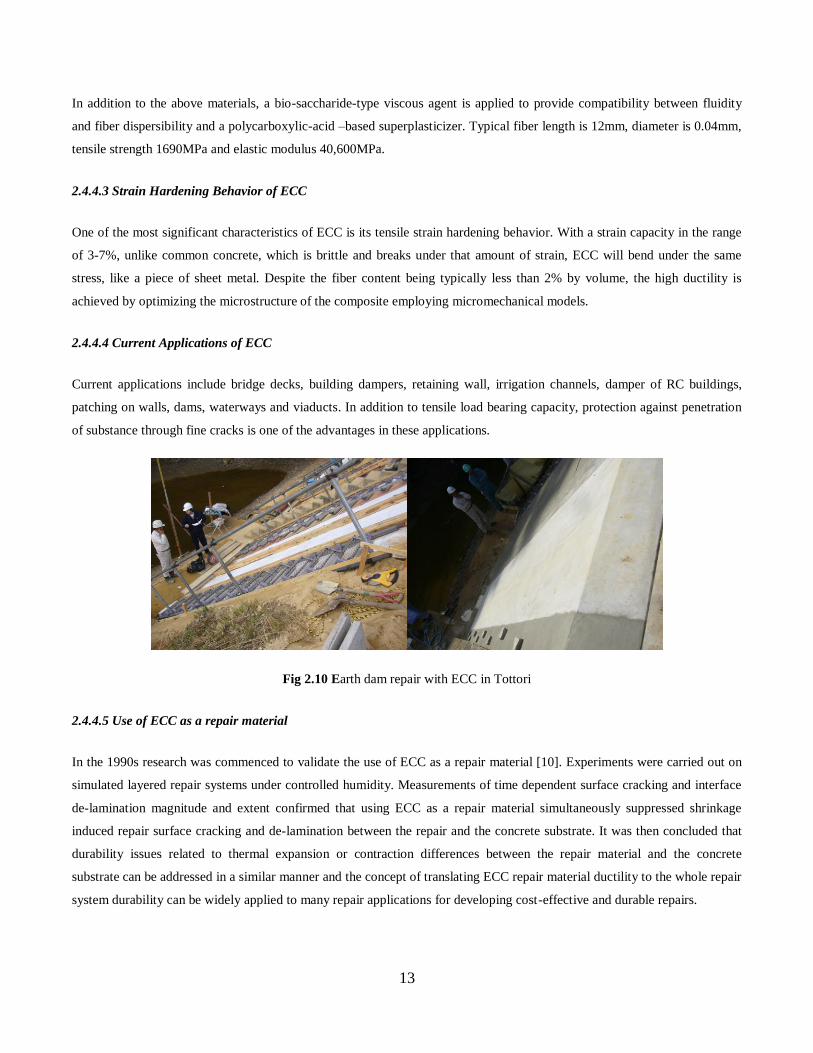
2.4.4.4 Current Applications of ECC
Current applications include bridge decks, building dampers, retaining wall, irrigation channels, damper of RC buildings,
patching on walls, dams, waterways and viaducts. In addition to tensile load bearing capacity, protection against penetration
of substance through fine cracks is one of the advantages in these applications.
Fig 2.10 Earth dam repair with ECC in Tottori
2.4.4.5 Use of ECC as a repair material
In the 1990s research was commenced to validate the use of ECC as a repair material [10]. Experiments were carried out on
simulated layered repair systems under controlled humidity. Measurements of time dependent surface cracking and interface
de-lamination magnitude and extent confirmed that using ECC as a repair material simultaneously suppressed shrinkage
induced repair surface cracking and de-lamination between the repair and the concrete substrate. It was then concluded that
durability issues related to thermal expansion or contraction differences between the repair material and the concrete
substrate can be addressed in a similar manner and the concept of translating ECC repair material ductility to the whole repair
system durability can be widely applied to many repair applications for developing cost-effective and durable repairs.

14
2.4.4.6 Application to repair of earth hydraulic structures
To date research has focused on the use of ECC for the repair of concrete structures. On the other hand, regular concrete has
also been the main repair material for earth hydraulic structures. In most cases, subsequent to uprooting of trees and shrubs,
inspections are carried out to confirm that all major root systems have been removed. Following inspection and approval of
the undercut area by the engineer, suitable backfill should be placed in the excavation and properly compacted to the dam
remediation design limits. In conjunction with the undercutting and backfilling, a slope protection system such as a rigid
(concrete) upstream embankment slope protection system or a concrete slab is placed directly on the upstream slope above
the normal pool elevation to deter future tree and woody vegetation growth and reduce the potential for wave and surface
runoff erosion. While this system is somewhat limited relative to the area of protection, the most critical aspect of this system
is that it provides no filtration and/or drainage system beneath the concrete slab. However, the deficiencies of concrete repair
systems such as excessive cracking discussed earlier often compromise the durability of such repair structures leading to
repair failures. Moreover, continual wave action and the buildup of hydrostatic pressures beneath the concrete slab will
eventually result in downward movement of the slab. While it has been proven that ECC can give more durable repair
systems for concrete structures, its durability in the repair of earth hydraulic structures is yet to be elucidated. Therefore, this
study was carried out to clarify if ECC can also be an effective repair material in earth dams and canals. The investigations
carried out are detailed in the next chapter.

15
CHAPTER 3: METHODOLOGY
This study comprised 4 sets of investigations entitled:
1. Effectiveness of ECC in curtailing re-emergence of weeds on an earth embankment
2. Effect of D-galacturonic acid on hydration of cementitious materials
3. Effect of cyclic loads on the surface profile of engineered cementitious composites (ECC) linings
4. Effect of plate thickness on crack propagation characteristics of engineered cementitious composites (ECC)
A premix of ECC with mix proportions as shown in Table 3.1 was used in this study.
Table 3.1 Mix proportion of premix premix ECC (1m3)[81]
ECC pre-mix*
(kg)
water
(200c)(kg)
admixture –
type A(kg)
admixture –
type B(kg)
admixture –
type C(kg)
1,562.50 350.00 16.88
15.25
3.13
(diluted 25 times)
*ECC premix composition: sand/cement=0.65 fly ash/cement=0.3 PVA fiber volume fraction=2%
Ordinary mortar was used as comparison since ECC is a mortar based mix and contains no coarse aggregate. Moreover,
ordinary mortar and not concrete is normally used in thin layer repair applications as targeted in this study.

16
3.1 EFFECTIVENESS OF ECC IN CURTAILING RE-EMERGENCE OF WEEDS ON EARTH EMBANKMENTS
3.1.1. Introduction
The establishment and control of proper vegetation is an important part of earth dam maintenance. Properly maintained
vegetation can help to prevent the erosion of the embankment and aids in the control of burrowing animals. However, the
intrusion of weeds in the form of trees and brushes impairs the durability of the embankment. Extensive root systems of
weeds provide seepage paths for water, while trees that fall over can leave large holes on the embankment surface. Such
occurrences weaken the embankment, making it susceptible to further erosion. In addition, brush obscures the embankment
surface and limits close inspections. Brush also provides a haven for burrowing animals and impedes the growth of desired
grass vegetation. Regular maintenance of vegetal cover is therefore necessary to recover or improve the embankment
durability.
Maintenance techniques commonly employed are grass mowing and brush cutting. Methods used in the past for the
vegetation control, which are now obsolete, include chemical spraying and burning [14]. Complete removal of stumps and
roots of weeds is necessary to curtail their re-emergence. The stumps can be removed either by pulling or with machines that
grind them down. This exercise severely distorts the embankment surface. In order to restore the surface, it is therefore
necessary to undertake massive earthworks to dispose waste soil and import suitable fill of required strength and
imperviousness to water. Procurement of the disposal site and fill source is an intricacy that has resulted in the failure of
commencement of several scheduled dam repair works [15]. There is need therefore, to employ a more viable technique.One
such technique involves the cutting of weeds on the surface and covering them with a suitable repair material that can curtail
their re-emergence. Weeds, like all other plants proliferate through the process of photosynthesis. Photosynthesis is the
process by which plants naturally synthesize carbohydrates and grow. Light is a key factor for this process to occur [16].
Photosynthetically active radiation measured as photosynthetic photon flux density (PPFD), is required to convert
atmospheric CO2 and water into essential organic compounds by the plants. Concurrently, they produce CO2 during
respiration. Generally, photosynthesis cannot occur under low light intensity but as the intensity increases, the process also
increases up to a compensation point that permits it to compensate for the plant’s respiratory needs. After the compensation
point, a plant can gain carbon and thus grow [17]. Therefore, preventing the process of photosynthesis from occurring
consequently curtails the re-emergence of weeds on the surface of an earth embankment. Selection of a suitable repair
material is critical for the effectiveness of this technique. Such a material must prevent photosynthesis from occurring and
still maintain the structural integrity of the embankment. It must also be tenacious to excessive deformation due to the
inevitable differential settlement of the earth embankment Any cracks produced by the repair material must be small enough
to restrict access of light, a key element for the photosynthesis of the weeds. In this way, the process can be prevented. The
use of stabilized muddy sediments as fill soil is one technique currently being developed [15].However, the rigorous process
of acquiring the sediments from below the dam complicates this technique. Asphaltic concrete is a flexible material that can
resist deformation due to differential settlement [18], but its low strength allows certain plants such as bamboo and puffball
fungus to shoot through [19]. Plain cement materials such as cement pastes, mortars and concretes are commonly used for
construction. The brittleness of these materials due to the production of a Griffith type [29] crack of unlimited width
17
diminishes their capacity to perform desired structural functions. The cited brittleness under severe loading of concrete for
instance, deterioration under normal service load and lack of sustainability of its reinforced structures [20] compromises both
its early age performance and long-term durability. Therefore, as a repair material, it produces structures with poor durability
susceptible to aggressive environments and prone to endless, uneconomical cycle of repairs [21]. For its water retaining
structures, the British Code BS 8007(1987) [ref. 10.19] states that a maximum crack width of 0.2mm is deemed adequate for
water tightness and a more stringent 0.1mm is necessary where aesthetic appearance is of particular importance. It is
believed that cracks less than 0.2mm heal autogenously as water percolates through the cracks and dissolves calcium salts in
the cement preventing leakage. The concrete repair layer must therefore meet this standard to maintain water tightness.
Ordinary mortar, formed by a mixture of cement, water and fine aggregate sand has high workability and hence is easy to
handle on site. However, like other plain cement materials, it is brittle, and exhibits deficiencies similar to those of concrete.
In addition, it has low strength, inferior extensibility and undergoes significant drying shrinkage. Consequently, mortar easily
develops shrinkage cracks [33]. The compression strength of a repair material is not the only measure of its ability to achieve
durability of a repair structure. While compression strength is significant in structural repairs, other factors such as shrinkage,
tensile strength and the adhesive bond strength to the substrate are significant for the failure of the repair and consequent
reduction of its durability [35]. Efforts to address the brittle behavior of plain cement materials have led to modern concepts
of fiber reinforcement and interface engineering [22].Engineered Cementitious Composites (ECC), a member of the High
Performance Fiber Reinforced Cement Composites (HPFRCC) group, is a fiber reinforced cement based composite material
that is excellent at crack dispersion. It is also formed mainly from cement and sand with fiber and certain chemicals as
additional materials. ECC is systematically engineered to achieve high ductility under tensile and shear load. It can achieve
maximum ductility in excess of 3% under uni-axial loading with only 2% volume of fiber content. It has a strain capacity
500times that of normal concrete or other fiber reinforced concrete [31]. It produces multiple fine cracks less than 0.1mm.
The tight crack width of ECC is important to the serviceability of ECC structures as the tensile ductility is to the structural
safety at ultimate limit state [17].In addition to tensile load bearing capacity, protection against penetration of substances by
the fine cracks is another advantage of ECC [22]. The fine cracks can alter corrosion mechanism of rebars within the
HPFRCC from macro-cell corrosion with a fast rate to micro-cell corrosion with a slow rate. In Japan, the fine cracking
mode of ECC which limits permeation of water, has led to its application in the repair of dams and irrigation surfaces among
other uses [23]. In this study, the effectiveness of ECC in restricting the penetration of light to weed stumps to prevent
photosynthesis and curtail the re-emergence of weeds was investigated. Ordinary mortar, a plain cement material was used as
a comparison.
3.1.2. Experimental Program
Two sets of experiments were carried out, one in the laboratory and the other in the field. In the laboratory, crack width,
crack density and luminance (the amount of light that passes through or is emitted from a particular area) through ECC and
mortar plates were measured. In the field, ECC and mortar plates were cast over freshly mowed bamboo stumps and
embedded with strain sensors. The re-emergence of shoots was monitored by measuring the strain within the plates for 6
months. The height of shoots from bamboo stumps with no plate cover was concurrently measured.

18
3.1.2.1 Materials
The materials used in the experiments were ECC and ordinary mortar. The target weed was Sasa Senanensis, which is a
bamboo variety. Bamboo was selected due to its high growth speed [24] and production of significant shooting forces [25].
All species of the bamboo tribe have C-3 photosynthesis [26] and hence do not need full sunlight to photosynthesize as
opposed to C-4 plants which photosynthesize more efficiently under full sunlight. Therefore, Sasa Senanensis is indicative of
plants with lower light and consequently lower PPFD requirements.
The mix proportions of ECC are shown in Table 3.1. ECC premix powder was used in this experiment. The major
components of the ECC premix powder were cement, sand and poly-vinyl alcohol (PVA) fiber (2% by volume) of length
12mm, diameter 0.04mm, tensile strength 1690MPa and modulus of elasticity 40,600MPa. At a room temperature of 200C,
the premix ECC powder was added to an electric mixer. Water and 3 admixtures, type A (superplastisizer), type B (anti-
shrinkage agent) and type C (expansive agent for air content adjustment) were mixed together and added to the premix
powder at once. The mixer was covered and run for 2 minutes to avoid losses of the mix components. While the mixer was
running, its cover was removed and mixing was continued until 10minutes elapsed. The ECC paste was then transferred into
a tray. The homogeneity of the mix was corroborated by further hand mixing.
Ordinary mortar was cast by mixing water, cement and sand to the following ratios: water/cement =0.5 and sand/cement = 3.
The procedure was done in accordance with the ASTM C305-99 standard.
3.1.2.2 Testing Procedure
a. Measurement of luminance
ECC and mortar plates of dimensions 400mm x 400mm x10mm ECC were cast and water cured for 28days at 200C.The plate
dimensions were selected to fit the limits of the bending machine used for generation of cracks .The 10mm thickness was
selected to match the minimum possible thickness for placing ECC layers using the direct spraying method [27]. Three sets
of ECC plates were prepared. Each set comprised 3 plates. The first set was the control and hence was kept intact. Using the
‘Third-Point Loading’ test [34] configuration, the second set was loaded to ultimate failure to determine the average ultimate
failure load. Using 80% of the determined average ultimate failure load (Fig.3.1.1), cracks were generated on the third set.
The plates were turned over to generate cracks on both sides. Two sets of mortar plates were prepared, each set also
comprising 3 plates. The control set was left intact while the plates in the second set were loaded until a through crack
developed. The loading configuration was the same as for the ECC plates.
Luminance was then measured on the set of ECC plates with cracks and the set with no cracks. A 1mm wide crack was made
on each mortar plate by pushing the 2 broken pieces of mortar together and adjusting them until readings from a device for
measuring the width of cracks on the surface of concrete structural walls Crack Viewer FCV-30 showed an average width of
1mm. The 1mm crack width was selected as the worst case scenario for ordinary concrete or mortar. Luminance was again
measured on the set of mortar plates with a 1mm wide crack and the set with no cracks. The test was implemented in a dark

19
room, with all external light sources eliminated. Each test plate was placed on a platform and illuminated by 2 tungsten bulbs,
each with wattage of 150W (Fig.3.1.2).Luminance readings were read from the light meter placed below the plate. Three
readings were taken on each plate to determine its average luminance. The average luminance from the 3 plates in each set
was then used to obtain the average luminance for the set.
b. Determination of crack density
A 100mm wide strip at the center of both the top and bottom sides of each ECC test plate was marked. The marked strip was
thinly painted using fluorescent paint to accentuate the cracks on the plate. In a dark room, each plate was illuminated under
black light. The fluorescent paint in the cracks glowed yellow under the light. Using a digital camera, pictures were taken at 3
positions on the strip. Images from the camera were viewed using a computer aided drafting software application AutoCAD
(Fig.3.1.3a). The quantity of cracks along 3 positions on the 100mm wide strip was physically counted from the images to
determine the average density of the cracks. This average was then multiplied by 10 to obtain the average quantity of cracks
per unit meter. However, since a single through crack was produced in each mortar plate, this method was not applicable in
determining the crack density in mortar. Instead, visual inspection was used to determine the number of cracks on each plate.
Fig.3.1.1.Generation of cracks using a bending machine
Fig.3.1.2.Illumination of an ECC plate by 2 tungsten bulbs, each with wattage of 150W

20
c. Measurement of crack width
Crack width measurements were carried out on 3 cracks on each of the 3 ECC plates used in this test to determine the average
crack width. The crack width was measured using the Crack Viewer FCV-30. The device was connected to a computer and
the device sensor was placed on the surface of the test plate. The crack width data and images obtained for each crack was
recorded directly from the laptop screen (Fig.3.1.4). Again for mortar, a through crack of unlimited width was produced and
so this method was not applicable.
(a) (b)
Fig.3.1.3.(a)10mm ECC plate with multiple fine cracks (b)10mm mortar plate with 1 through crack
crack width data (mm)
average crack width (mm)
measured crack
Fig.3.1.4.Image and data from the Crack Viewer FCV-30 for a 10mm ECC plate

21
d. Measurement of strain
The Sasa Senanensis was mowed and stumps leveled to the ground. Fresh ECC and mortar was cast over the bamboo stumps
into plates of dimensions 1000mm x 500mm x 10mm.The surface dimensions were selected to allow a significant number of
bamboo stumps to be covered (average 15 stumps). The plates were embedded with 3 strain sensors along the middle strip
(250mm from the 1000mm edge, Fig.3.1.5) .The right and left sensors were embedded 50mm from the 500mm edge. The 3rd
sensor was embedded 495mm from the 500mm edge. All sensors were embedded 2mm below the surface of the plates as
shown in section A-A in Fig.3.1.6. Steel anchors were used to fix the plates to the ground. Strain readings were collected
from the sensors periodically for 6 months using a digital strain meter TC-31K.Visual inspections were concurrently carried
out on the plates.
Two controls were established. The first control was in the form of ECC and mortar plates cast over bare soil with no
bamboo stumps underneath. The second control was established by measuring the height of shoots from 3 bamboo stumps
with no plates covering them. The shoots were labeled B-1, B-2 and B-3. A measuring tape was used for this test. The height
readings were collected concurrently with strain readings.
Fig.3.1.5.Schematic diagram of ECC and mortar plates showing bamboo stumps and strain sensor positions
3.1.3. Results
3.1.3.1 Luminance, crack width and crack density
The luminance of the dark room was 0. The average luminance through ECC and mortar plates is shown in Table 3.2. The
ECC plates produced multiple fine cracks but the mortar plates produced a single though crack of unlimited width shown in
Fig.3.1.3. The average crack width and average crack density for ECC plates is shown in Table 3.3. An image of a measured
crack and corresponding data from the Crack Viewer FCV-30 is shown in Fig.3.1.4.

22
Table 3.2 Average luminance through 10mm ECC and mortar plates
no cracks with cracks
(lx) (µmol m-2
s-1
)* (lx) (µmol m-2
s-1
)*
ECC 0.36 7.20x10⁻³
1.46 2.92x10⁻²
mortar 0.21 4.20x10⁻³
27.00 5.40x10⁻¹
*To convert lx to µmol m-2 s-1 divide lx value by 50[15]
Table 3.3 Average crack density and crack width for 10mm ECC plates
bottom density top density average density average density average crack width
(cracks /100mm) (cracks /100mm) (cracks/ 100mm) (cracks/ m) mm
12.75 12.50 12.63 126.30 0.09
3.1.3.2 Bamboo shoots growth and strain variations in ECC and mortar plates
The bamboo shoots emerged from the soil around the ECC and mortar plates 21 days after casting .The variation in height of
the shoots B-1, B-2 and B-3 from the control stumps is shown in Fig.3.1.6. Neither shoots nor visible cracks were observed
on top of the plates. The variation of strain with time for the ECC and mortar plates is shown in Fig.3.1.7. Each graph
represents results from the 3 strain gauges on a particular plate. The location of the gauges within the plates is schematically
shown in Fig.3.1.5. Graphs 1 and 3 represent the results from plates 1 and 3 which are the ECC test and control plates
respectively. Graphs 2 and 4 represent the results from plates 2 and 4 which are the mortar test and control plates respectively.
Each line on the graph represents readings from a particular strain sensor in a plate. The left, middle and right sensors are
denoted as sensor 1, 2 and 3 respectively. The strain sensor is therefore denoted by 2 digits x-y. The left digit(x) represents
the plate number and the right digit(y) represents the position of the sensor thus, line 1-2 represents readings from the strain
sensor on position # 2 of plate # 1.
Bamboo Shoot Height Against Time
0
200
400
600
800
1000
1200
1400
0 2 4 6 8 10 15 23
Time(week)
Heig
ht(
mm
)
B-1
B-2
B-3
Fig.3.1.6 Variation of height of bamboo shoots B-1, B-2 and B-3 with

23
3.1.4. Discussion
3.1.4.1 Luminance through ECC and mortar plates
Fig.3.1.7.Graphs of Strain (x10-6
) against time (weeks) for 10mm ECC and mortar plates
It was determined that an average luminance of 0.0072µmol m-2
s-1
and 0.0042µmol m-2
s-1
penetrated the ECC and mortar
plates with no cracks respectively. This means the luminance through the mortar plate with no cracks was 58% less than
luminance through the corresponding ECC plate. The density of the mortar and ECC plates measured just before the
experiment was 2482kg/m3 and 1926kg/m
3 respectively. This means that the particles in the mortar plate before crack
generation were more tightly packed than the particles in the ECC plate and hence allowed less light to penetrate as reflected
by lower measured luminance. On the other hand, an average luminance of 0.0292µmol m-2
s-1
penetrated the ECC plate
with cracks while 0.54µmol m-2
s-1
penetrated the mortar plate with a single 1mm crack. This means 18 times more light
penetrated the mortar plate with a single 1mm through crack than the ECC plate with multiple fine cracks (126.3cracks/m,
0.09mm diameter). Inferring to the crack propagation patterns of ECC and mortar, the localized fracture due to Griffith crack
propagation characteristic of mortar resulted in a through crack which allowed significant light to penetrate through, whereas
Graph 1 Graph 2
Graph 3 Graph 4
Strain Against Time
(10mm ECC plate over bamboo stumps)
-100
100
300
500
700
900
1100
1300
1500
0 2 4 6 8 10 15 23
Time(weeks)
Str
ain
(x10
-6)
1-1
1-2
1-3
Strain Against Time
(10mm mortar plate over bamboo stumps)
-100
100
300
500
700
900
1100
1300
1500
0 2 4 6 8 10 15 23
Time(weeks)
Str
ain
(x10
-6)
2-1
2-2
2-3
Strain against time
(10mm ECC plate ,control)
-100
100
300
500
700
900
1100
1300
1500
0 2 4 6 8 10 15 23
Time(weeks)
Str
ain
(x10
-6)
3-1
3-2
3-3
Strain against time
(10mm mortar plate,control)
-100
100
300
500
700
900
1100
1300
1500
0 2 4 6 8 10 15 23
Time(weeks)
Str
ain
(x10
-6)
4-1
4-2
4-3
24
the characteristic strain-hardening after the first cracking of the ECC resulted in multiple micro-cracking on the surface of the
plate which were more restrictive to the penetration of light [31].
From Table 3.2, it was deduced that before the generation of cracks, both plates prevented the penetration of significant
amounts of light. However, after the generation of cracks, 4 times more light penetrated the ECC plates with cracks than
without while 129 times more light penetrated the mortar plates with a single 1mm through crack than with no cracks. This
shows that the single through crack of the mortar plate greatly depleted its capacity to prevent the penetration of light and
comparatively, the effect of fine ECC cracks was less severe .This observation confirms the deficiencies associated with plain
cement materials as repair materials pitted against the advantages of ECC cited in the introduction to this paper . The
brittleness of the mortar under severe loading caused the through crack which enabled significant amounts of light to pass
through. This characteristic then exposed any underlying structures to the aggressive environment [21]. However, ECC, due
to its high strain capacity produced multiple fine cracks with 0.09mm average diameter on the surface. These cracks managed
to significantly restrict the penetration of light.
3.1.4.2 Crack width and crack density of ECC and mortar plates
The 10mm mortar plates produced a single through crack but the 10mm ECC plates produced multiple fine cracks of average
width 0.09mm. This shows that the mortar, which is brittle produced the common form of localized fracture due to Griffith
crack propagation [29] whereas the cracks in ECC were bridged by the PVA fibers in the material and hence the resulting
small widths [30]. The characteristic strain-hardening after the first cracking of the ECC resulted in the multiple micro-
cracking. This tight crack width by ECC is self-controlled and, whether the composite is used in combination with
conventional reinforcement or not, it is a material characteristic independent of rebar reinforcement ratio. In contrast, mortar,
like ordinary concrete and fiber reinforced concrete relies on steel reinforcement for crack width control [20].
3.1.4.3 Strain Variations in ECC and mortar plates
In general, a decrease in strain indicates the occurrence of contraction in a material while an increase in strain indicates the
occurrence of expansion. As shown in the graphs in Fig.3.8, all the ECC and mortar test and control plates experienced initia l
contraction from the time of casting up to the 4th week after which the plates gradually expanded until the 15
th week.
Thereafter, contraction resumed. Therefore, there are no significant differences in strain variations within the ECC and mortar
test and control plates throughout the test period. Given that strain varies in response to external forces, the absence of a clear
distinction in the strain variations in the plates indicates that there was no major difference in the underlying forces. Since
both the test and control plates were subjected to the same conditions except the presence of the bamboo stumps underneath
the test plates, it was expected that if the bamboo stumps produced shoots, elastic forces exerted by the bamboo shoots would
cause additional elastic strain to the test plates. No corresponding elastic strain was expected on the control plates (no
bamboo stumps underneath). If enough light penetrated the overlying plates the bamboo stumps were expected to shoot,
photosynthesize and grow. Since the test plates were anchored to the ground, the forces of the bamboo shoots would then
cumulatively exert stresses on the plate causing deformation in the form of bending of the plate. The bending would then
causes relative displacement between particles in the material body within the plate in the form of elastic strain. This process

25
was expected to commence at the time the bamboo shoots started appearing on the bamboo stumps with no covering (second
control) i.e. 21days after casting (Fig.3.1.6). Any increase in strain from this point onwards on the plates over bamboo
stumps only and no corresponding strain increase on control plates could thus be attributed to the force from the bamboo
shoots. However from the graphs in Fig.3.1.7, no significant difference in strain between the plates over bamboo and control
plates was observed from the aforementioned 21 days and throughout the growing period of the control bamboo shoots
affirming that the bamboo stumps below the ECC and mortar plates did not shoot.
This observation concurs with the results from the luminance experiment. Since the ECC and mortar plates used for the strain
measurement test were cast in situ and no cracks were generated, the properties of these plates thus match the properties of
the ECC and mortar plates with no cracks used in the luminance experiment. From table 3.2, the luminance of the ECC and
mortar plates with no cracks was 0.0072µmol m-2
s-1
and 0.0042µmol m-2
s-1
respectively. The minimum PPFD for Sasa
Senanensis is 3.4molm-2
day-1
[3] i.e. 0.039µmol m-2
s-1
. This means that Sasa Senanensis requires at least 0.039µmol m-2
s-1
of
PPFD to photosynthesize. Since the minimum value of PPFD required for the photosynthesis of the Sasa Senanensis is more
than the average amount of light that penetrated both the ECC and mortar plates with no cracks, the bamboo stumps could
therefore not photosynthesize. Consequently no elastic forces could be generated by bamboo shoots to cause significant
variations in the strain of the test plates.
On the other hand, 0.0292µmolm-2
s-1
of light penetrated the ECC plate with cracks while 0.54 µmol m-2
s-1
penetrated the
mortar plate with a single 1mm crack. This means that the luminance through the ECC plate with cracks was also less than
the minimum PPFD required for the photosynthesis of Sasa Senanensis. Consequently, the 10mm ECC plate with cracks can
also prevent the photosynthesis of Sasa Senanensis .However, the luminance though the mortar plate with a single 1mm
crack was more than the minimum PPFD required for the photosynthesis of Sasa Senanensis. Therefore, the mortar plate with
a single 1mm crack can allow enough light for the photosynthesis to occur. In addition, the mortar characteristic through
crack produced by mortar makes it susceptible to further lateral and vertical movements in response to the differential
settlement of earth embankments. Such movements can cause further expansion of the crack which in turn increases its light
penetration capacity. The bamboo shoots can then grow further and continue to expand the crack. Once the crack width
exceeds serviceability limits, durability failure ensues.
In view of the foregoing discussion, other factors characteristic of cementitious materials can be attributed to the variations in
strain in the ECC and mortar plates. After casting, the ECC and mortar plates underwent autogeneous shrinkage until the 4th
week. In addition to plastic shrinkage which occurs when the cement paste in the cementitious material is still in its plastic
state, volume change, in the form of either shrinkage or swelling continues to occur after setting of the material has taken
place. The withdrawal of the hitherto unhydrated cement results in autogeneous shrinkage which occurs in the interior of the
material mass. Since the contraction of the cement paste is restrained by the rigid skeleton of the already hydrated cement
paste, the magnitude of autogeneous shrinkage is very small, typically about 40 x 10-6
at age 1 month [19]. This typical value
of shrinkage at age 1 month is comparable to the values of strain in ECC and mortar at the same age (Fig.3.1.7). It was
observed that the values of the shrinkage strain of the ECC and mortar plates are almost the same. According to Japanese
Industrial Standards for Construction Materials and Building, JIS A 6203B, the shrinkage strain of ECC is almost the same as

26
that of concrete. After the 4th week, the thermal strain, which is directly proportional to variations in temperature, caused the
increase in strain in all the plates. The plates were cast at the beginning of April (spring) when temperatures were relatively
low .The average temperature recorded on the plates using a thermocouple was 210C in the 1
st 4 weeks. The temperatures
increased rapidly after 4 weeks (at the onset of summer) with average temperatures of 380C being recorded .After 15 weeks
temperatures began to decrease again (average 300C) as fall approached. This trend in temperature is matched by the trend in
the graphs in Fig.8 i.e. the increase in strain from the 4th week until the 15
th week followed by a decrease thereafter.
3.1.5. Conclusion
The following conclusions can be drawn from this study:
1. The 10mm ECC plate is effective in curtailing the re-emergence of Sasa Senanensis before and after the production
of cracks by preventing the penetration of sufficient light for its photosynthesis.
2. The 10mm mortar plate is effective in curtailing the re-emergence of Sasa Senanensis before the production of
cracks only. After the production of the typical single through crack, the mortar allows sufficient light for the
photosynthesis and subsequent re-emergence of the bamboo.
3. Since Sasa Senanensis is a C-3 photosynthesis plant ( lower light requirements for photosynthesis ), the ECC and
mortar plates with no cracks and the ECC plate with cracks can also curtail the re-emergence of all C-4
photosynthesis plants which need full sunlight (higher light requirements) to photosynthesize.
4. The high strain capacity of ECC results in the production of fine surface cracks which minimize the penetration of
light through the ECC plate thereby eliminating the possibility of photosynthesis of underlying weeds.
5. The fiber-bridging property across an ECC matrix crack gives the material ductility. Excessive deformation due to
any differential settlement of an earth embankment that causes expansion of any existing cracks is therefore minimal.
The restricted crack width and location of the cracks on the surface of the ECC plate entails that the ECC cracks are
not capable of hosting other flying seeds which have a potential to sprout, grow and expand the hosting crack. The
possibility of any underlying weed stumps accessing sufficient light for photosynthesis in future is therefore
eliminated.
6. The production of the typical Griffith type through crack in mortar or concrete makes the crack susceptible to further
expansion due to differential settlement of earth embankments. The expanded crack increases the quantity of light
available for weeds to photosynthesize and re-emerge. The expanded crack can also host flying seeds from other
weeds .These weeds can also sprout and grow which leads to further expansion of the crack and ultimate loss of
serviceability integrity of the structure.
7. Since the ECC cracks are resilient to further expansion due to the growth of weeds, the loss of serviceability
integrity of an embankment repaired by an ECC layer is unlikely. ECC is therefore an effective and durable repair
material on earth embankment surfaces.
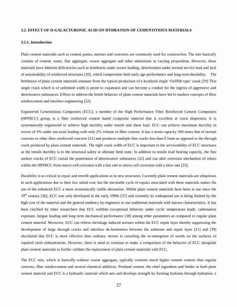
27
3.2. EFFECT OF D-GALACTURONIC ACID ON HYDRATION OF CEMENTITIOUS MATERIALS
3.2.1. Introduction
Plain cement materials such as cement pastes, mortars and concretes are commonly used for construction. The mix basically
consists of cement, water, fine aggregate, coarse aggregate and other admixtures in varying proportions. However, these
materials have inherent deficiencies such as brittleness under severe loading, deterioration under normal service load and lack
of sustainability of reinforced structures [20], which compromise both early age performance and long-term durability. The
brittleness of plain cement materials emanate from the typical production of a localized single ‘Griffith type’ crack [29] This
single crack which is of unlimited width is prone to expansion and can become a conduit for the ingress of aggressive and
deteriorative substances. Efforts to address the brittle behavior of plain cement materials have led to modern concepts of fiber
reinforcement and interface engineering [22].
Engineered Cementitious Composites (ECC), a member of the High Performance Fiber Reinforced Cement Composites
(HPFRCC) group, is a fiber reinforced cement based composite material that is excellent at crack dispersion. It is
systematically engineered to achieve high ductility under tensile and shear load. ECC can achieve maximum ductility in
excess of 3% under uni-axial loading with only 2% volume of fiber content. It has a strain capacity 500 times that of normal
concrete or other fiber reinforced concrete [31] and produces multiple fine cracks less than 0.1mm as opposed to the through
crack produced by plain cement materials. The tight crack width of ECC is important to the serviceability of ECC structures
as the tensile ductility is to the structural safety at ultimate limit state. In addition to tensile load bearing capacity, the fine
surface cracks of ECC curtail the penetration of deteriorative substances [22] and can alter corrosion mechanism of rebars
within the HPFRCC from macro-cell corrosion with a fast rate to micro-cell corrosion with a slow rate [23].
Durability is as critical in repair and retrofit applications as in new structures. Currently plain cement materials are ubiquitous
in such applications due to their low initial cost, but the inevitable cycle of repairs associated with these materials makes the
use of the enhanced ECC a more economically viable alternative. Whilst plain cement materials have been in use since the
19th century [36], ECC was only developed in the early 1990s [37] and currently its widespread use is being limited by the
high cost of the material and the general tendency by engineers to use traditional materials with known characteristics. It has
been clarified by other researchers that ECC exhibits exceptional behavior under cyclic temperature loads, carbonation
exposure, fatigue loading and long term mechanical performance [38] among other parameters as compared to regular plain
cement material. Moreover, ECC can relieve shrinkage induced stresses within the ECC repair layer thereby suppressing the
development of large through cracks and interface de-lamination between the substrate and repair layer [21] and [39]
elucidated that ECC is more effective than ordinary mortar in curtailing the re-emergence of weeds on the surfaces of
repaired earth embankments. However, there is need to continue to make a comparison of the behavior of ECC alongside
plain cement materials to further validate the replacement of plain cement materials with ECC.
The ECC mix, which is basically without coarse aggregate, typically contains much higher cement content than regular
concrete, fiber reinforcement and several chemical additives. Portland cement, the chief ingredient and binder in both plain
cement material and ECC is a hydraulic material which sets and develops strength by forming hydrates through hydration, a
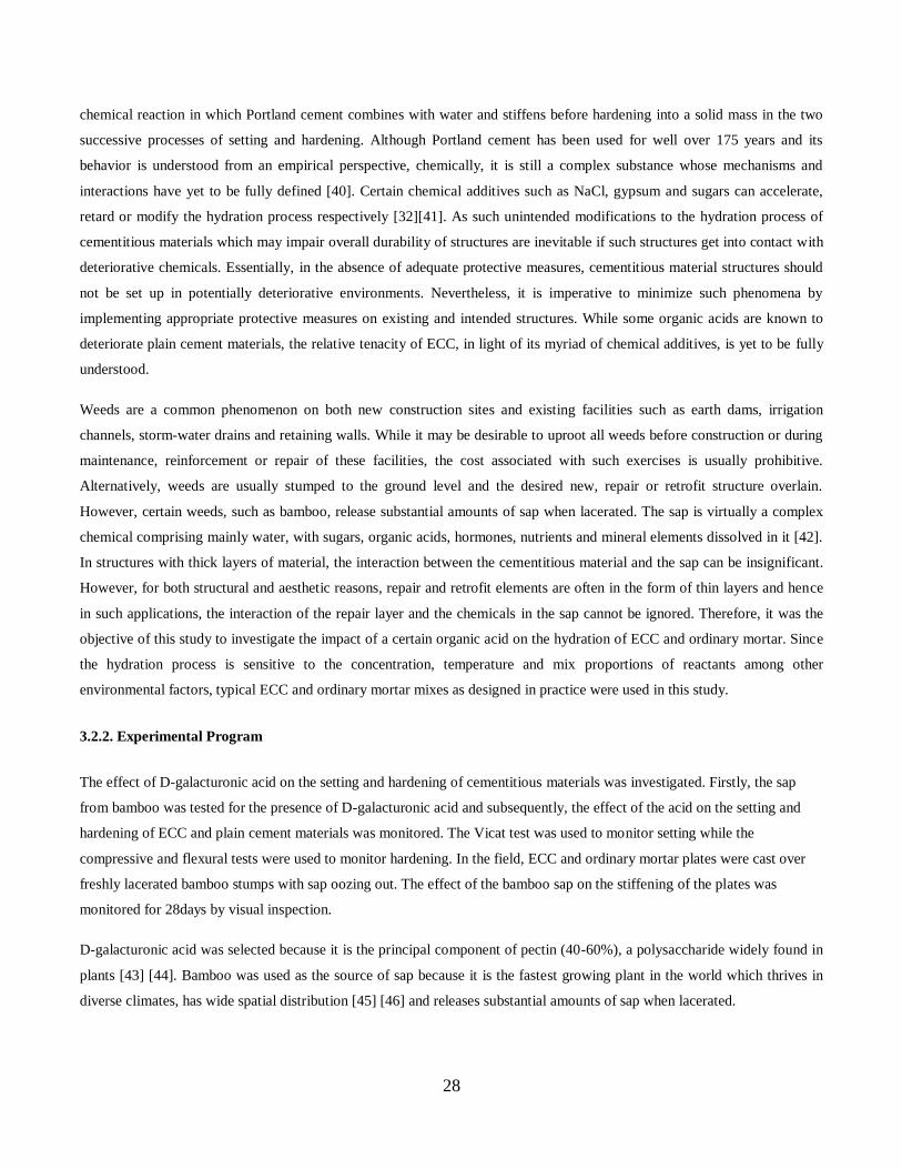
28
chemical reaction in which Portland cement combines with water and stiffens before hardening into a solid mass in the two
successive processes of setting and hardening. Although Portland cement has been used for well over 175 years and its
behavior is understood from an empirical perspective, chemically, it is still a complex substance whose mechanisms and
interactions have yet to be fully defined [40]. Certain chemical additives such as NaCl, gypsum and sugars can accelerate,
retard or modify the hydration process respectively [32][41]. As such unintended modifications to the hydration process of
cementitious materials which may impair overall durability of structures are inevitable if such structures get into contact with
deteriorative chemicals. Essentially, in the absence of adequate protective measures, cementitious material structures should
not be set up in potentially deteriorative environments. Nevertheless, it is imperative to minimize such phenomena by
implementing appropriate protective measures on existing and intended structures. While some organic acids are known to
deteriorate plain cement materials, the relative tenacity of ECC, in light of its myriad of chemical additives, is yet to be fully
understood.
Weeds are a common phenomenon on both new construction sites and existing facilities such as earth dams, irrigation
channels, storm-water drains and retaining walls. While it may be desirable to uproot all weeds before construction or during
maintenance, reinforcement or repair of these facilities, the cost associated with such exercises is usually prohibitive.
Alternatively, weeds are usually stumped to the ground level and the desired new, repair or retrofit structure overlain.
However, certain weeds, such as bamboo, release substantial amounts of sap when lacerated. The sap is virtually a complex
chemical comprising mainly water, with sugars, organic acids, hormones, nutrients and mineral elements dissolved in it [42].
In structures with thick layers of material, the interaction between the cementitious material and the sap can be insignificant.
However, for both structural and aesthetic reasons, repair and retrofit elements are often in the form of thin layers and hence
in such applications, the interaction of the repair layer and the chemicals in the sap cannot be ignored. Therefore, it was the
objective of this study to investigate the impact of a certain organic acid on the hydration of ECC and ordinary mortar. Since
the hydration process is sensitive to the concentration, temperature and mix proportions of reactants among other
environmental factors, typical ECC and ordinary mortar mixes as designed in practice were used in this study.
3.2.2. Experimental Program
The effect of D-galacturonic acid on the setting and hardening of cementitious materials was investigated. Firstly, the sap
from bamboo was tested for the presence of D-galacturonic acid and subsequently, the effect of the acid on the setting and
hardening of ECC and plain cement materials was monitored. The Vicat test was used to monitor setting while the
compressive and flexural tests were used to monitor hardening. In the field, ECC and ordinary mortar plates were cast over
freshly lacerated bamboo stumps with sap oozing out. The effect of the bamboo sap on the stiffening of the plates was
monitored for 28days by visual inspection.
D-galacturonic acid was selected because it is the principal component of pectin (40-60%), a polysaccharide widely found in
plants [43] [44]. Bamboo was used as the source of sap because it is the fastest growing plant in the world which thrives in
diverse climates, has wide spatial distribution [45] [46] and releases substantial amounts of sap when lacerated.

29
3.2.2.1 Materials
The cementitious materials used in this study were ECC and ordinary mortar. Bamboo sap was used to confirm the presence
of D-galacturonic acid in plants but the concentrated manufactured form of the acid was used in the experiments. Since the
micromechanics design of ECC is complex, for laboratory purposes, a premix with simple mixing instructions from the
manufacturer is more practical [47]. Therefore, the ECC used in this study comprised a premix ECC powder and chemical
additives mixed to instructions by the manufacturer. To simulate practical conditions, the mix proportions commonly used in
practice were selected for the ordinary mortar.
The ECC mix proportions are shown in Table 3.1. The components of the ECC premix powder were cement, sand, PVA
fiber and fly ash. The fiber was 12mm in length and 0.04mm in diameter with a tensile strength of 1690MPa and a modulus
of elasticity of 40,600MPa. The premix ECC powder was added to an electric mixer at a room temperature of 200C. Water
and the 3 admixtures, type A (poly carboxylic acid based superplasticizer), type B (CSA type anti-shrinkage agent) and type
C (poly oxi-alkaline based expansive agent for air content adjustment) were mixed together and added to the premix powder
at once. The mixer was covered and run for 2 minutes to avoid losses of the mix components. While the mixer was running,
its cover was removed and mixing was continued until 10 minutes elapsed. The ECC paste was then transferred onto a tray
and the homogeneity and uniform distribution of the fresh mix was corroborated by further hand mixing and any lumps
discarded.
The ordinary mortar was prepared by mixing sand, Portland cement and water to the following ratios: water/cement=0.5 and
sand/cement=3. The ASTM C305-99 was adhered to for the preparation.
Bamboo sap was extracted by soaking chopped pieces of bamboo reeds in pure water for 4 weeks. A 1mg/ml solution of D-
galacturonic acid was prepared by dissolving the acid powder in pure water at a ratio of 1mg of acid to 1ml of water. The
1mg/ml acid solution was further dissolved in pure water to produce 5 different aqueous solutions. The aqueous solutions
were made by pipetting a particular volume of the acid into a 100ml volumetric flask and making up to the 100ml mark with
pure water using the proportions shown in Table 3.4.
Table 3.4 Production of the D-galacturonic acid aqueous solutions in a 100ml volumetric flask
sample volume of 1mg/ml D-
galacturonic acid solution (ml)
concentration of D-galacturonic
acid aqueous solution (μg/ml)
pH
1. 0 0(pure water) 7
2. 2 20 6.9
3. 4 40 6.8
4. 6 60 6.7
5. 8 80 6.6

30
3.2.2.2 Testing Procedure
a.Chemical composition analysis of bamboo sap
The presence of D-galacturonic acid in the bamboo sap was ascertained chromatographically using the ‘Carbazole method’
[48] which is a standard test for the presence of uronic acids.
b. Setting time
Five ECC and ordinary mortar pastes were prepared by replacing the water component of the paste with the D-galacturonic
acid aqueous solutions of concentrations shown in Table 3.5. Measurements of pH were taken on the D-galacturonic acid
aqueous solutions and D-galacturonic acid aqueous solutions / ECC or ordinary mortar pastes soon after mixing. The final
setting time was then monitored using the ‘Vicat’ apparatus. The test was carried out to the ASTM C 807-03a standard.
c. Flexural and compressive strength
Standard ECC and ordinary mortar prisms of dimensions 40 mm x 40 mm x 160 mm were cast. Soon after de-moulding, 25%
-galacturonic acid aqueous solution and 75% were cured in pure water. The
curing temperature was 200
l D-galacturonic acid corresponded with the
highest concentration used in the setting time experiment. The samples were labeled as shown in Fig.3.2.1. Compressive and
flexural strength tests were carried out on sample A and a third of sample B at the age of 2, 7, 14, 21and 28 days. After 28
days, 50% of the remaining prisms from sample B were soaked in D-galacturonic acid to make sample C. Compressive and
flexural strength tests were continued on the hardened samples B and C fortnightly for a period of 56days. All compressive
strength tests adhered to the ASTM C349-02 standard while the flexural strength tests were carried out in accordance with
the ASTM C348-02 standard.
d. Effect of bamboo sap on the stiffening ECC and ordinary mortar plates
Bamboo reeds were stumped to the ground level. Fresh ECC and ordinary mortar were cast into plates of 1000 mm x 500 mm
x 10 mm dimensions over the stumps with sap oozing out. The dimensions 1000 mm x 500 mm were selected to enable a
sizeable number of bamboo stumps to be covered, while the 10mm thickness was selected as the minimum thickness that can
be practically applied on site using common application methods. Two controls were established in the form of plates of the
same dimensions cast over bare ground (control 1) and bamboo stumps which were left uncovered throughout the experiment
(control 2). The test plates and controls were visually inspected periodically from the time of casting up to 28 days.

31
Fig. 3.2.1.Details of the ECC and mortar samples used in the experiment
3.2.3. Results
The pH of the D-galacturonic acid aqueous solutions and the D-galacturonic acid aqueous solution/ECC or ordinary mortar
pastes are shown in Table 3.4 and Table 3.5 respectively. The effect of the acid aqueous solutions on the final setting time of
ECC and ordinary mortar is shown in Table 3.5. The rate at which the acid increased the setting time is shown in
Fig.3.2.2.The flexural and compressive strength of the mortar samples during the standard curing period (28 days) are shown
in Fig.3.2.3 and Fig.3.2.4 while the flexural and compressive strength of the hardened samples soaked in D-galacturonic acid
after 28days of pure water curing are shown in Fig.3.2.5 and Fig.3.2.6.
The ECC and mortar plates cast on bare ground (control plates) stiffened and dried up completely within 24 hours as
expected. However, unstiffened circular patches were concurrently observed on the ECC and mortar plates cast over bamboo
stumps (Fig.3. 2.7). The circular unstiffened patches corresponded to the positions of the underlying bamboo stumps. In
addition, excess fluid was observed on the mortar patches. At the age of 2 days after casting, the ECC patches had stiffened
like the rest of the plate. On the other hand, the unstiffened wet patches persisted on the mortar plates for a period of more
than 14 days during which the fluid gradually decreased in intensity and changed in coloration from colorless to yellowish
(Fig.3.2.8). On the 21st day after casting, the yellowish fluid finally dried up but no mass mortar was formed. Instead,
disaggregated sand and cement-like material remained on the previously moist patches (Fig.3.2.9) of the worst affected
section. As time progressed, the disaggregated material was eroded by the rain and circular holes remained in the mortar
through which the underlying bamboo stump could be observed (Fig.3.2.10).
All 40mmx40mmx160mm prisms cast
Samples cured in 80mg/ml D-galacturonic aqueous solution
for 28 days (A)
Samples cured and kept in pure water throughout the experiment
(B)
Samples cured in water and transferred to 80mg/ml D-
galacturonic aqueous solution after 28 days(C)

32
Table 3.5 pH of ECC and ordinary mortar soon after mixing with D-galacturonic acid aqueous solution
sample concentration of D-galacturonic
acid aqueous solution (μg/ml) in
mix
ECC ordinary
mortar
1. 0(pure water) 11.83 12.85
2. 20 11.69 12.55
3. 40 11.53 11.74
4. 60 11.46 11.20
5. 80 11.38 10.44
Table 3.6 Effect of D-galacturonic acid on the final setting time of ECC and ordinary mortar
concentration of D-galacturonic
acid aqueous solution (μg/ml)
final setting time
(min)
ECC ordinary
mortar
1. 0 510 285
2. 20 530 310
3. 40 545 525
4. 60 564 590
5. 80 575 880
0
50
100
150
200
250
0 20 40 60 80
Concentration of D-galacturonic acid(mg/ml)
Incre
ase
in
fin
al
sett
ing
tim
e(%
) ordinary mortar
ECC
Fig.3.2.2.Rate of increase in final setting time of ECC and ordinary mortar due to
D-galacturonic acid
0
5
10
15
20
25
30
35
40
0 2 7 14 21 28
Age(days)
Co
mp
ress
ive s
tren
gth
(MP
a)
mortar(A)
mortar(B)
ECC(A)
ECC(B)
0
5
10
15
20
25
0 2 7 14 21 28
Age(days)
Fle
xu
ral
stre
ng
th(M
Pa)
mortar(A)
mortar(B)
ECC(A)
ECC(B)
Fig.3.2.4.Compressive strength of ECC and
mortar cured in acid(A) and water(B)
Fig.3.2.3.Flexural strength of ECC and mortar
cured in acid (A) and water (B)
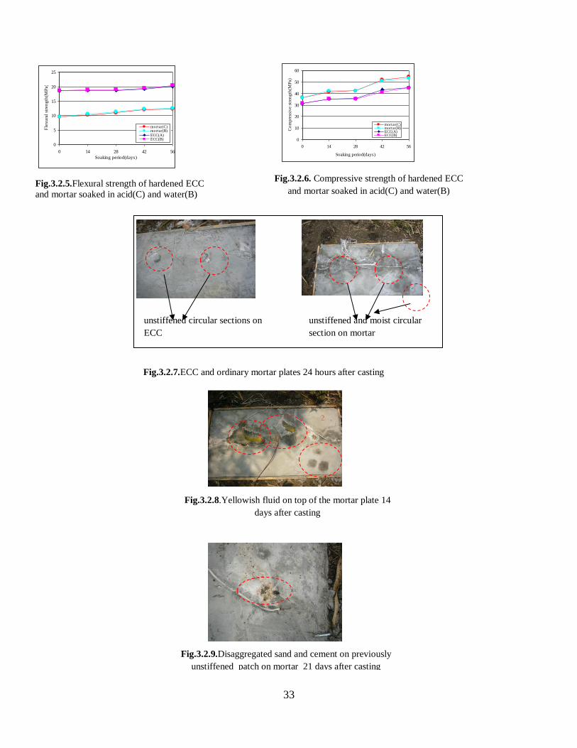
33
unstiffened and moist circular
section on mortar
unstiffened circular sections on
ECC
Fig.3.2.8.Yellowish fluid on top of the mortar plate 14
days after casting
Fig.3.2.9.Disaggregated sand and cement on previously
unstiffened patch on mortar 21 days after casting
0
5
10
15
20
25
0 14 28 42 56
Soaking period(days)
Fle
xu
ral
stre
ng
th(M
Pa)
mortar(C)mortar(B)ECC(A)ECC(B)
Fig.3.2.6. Compressive strength of hardened ECC
and mortar soaked in acid(C) and water(B)
Fig.3.2.7.ECC and ordinary mortar plates 24 hours after casting
Fig.3.2.5.Flexural strength of hardened ECC
and mortar soaked in acid(C) and water(B)
0
10
20
30
40
50
60
0 14 28 42 56
Soaking period(days)
Co
mp
ress
ive s
tren
gth
(MP
a)
mortar(C)mortar(B)ECC(A)ECC(B)

34
3.2.4. Discussion
a. Effect on setting time
The circular unstiffened patches on the ECC and mortar plates can be attributed to D-galacturonic acid contained in the sap
from the bamboo stumps underlying the plates due to the shape and positioning. On the other hand, as shown in Table 3.6,
the setting time of both ECC and ordinary mortar increased with increase in the concentration of the D-galacturonic acid.
While the setting time of ECC was higher than that of the ordinary mortar at lower concentrations of the acid, the setting time
of the ordinary mortar eclipsed that of ECC as the concentration of the acid increased. Hence, at the highest concentration o f
D-galacturonic acid used in this experiment, 80μg/ml, the rate of increase in the setting time of ECC and the ordinary mortar
was 13% and 208% respectively. This shows that the setting retardation effect of the acid was more severe on the ordinary
mortar than on ECC as concentration of the acid increased as was also confirmed in the field where the unstiffened patches
on ECC lasted only 2 days relative to more than 14 days observed on the mortar plates. However, as shown in Fig.3.2.2, at
lower concentrations of D-galacturonic acid, the setting time of ECC was higher than that of the ordinary mortar. This is due
to the influence of the polycarboxylic acid based superplasticizer present in the ECC mix. Whilst it has been proved that
shrinkage reducing agents have a negligible effect on setting time [49], most superplasticizers generally tend to decrease
setting time [50]. However, the polycarboxylic acid based superplasticizer in the ECC mix is known to retard setting time if it
is used in low dosage [51] as in this study.
The impact of D-galacturonic acid on the setting time of ordinary mortar and ECC can be further explained as follows. D-
galacturonic acid is an uronic acid or ‘sugar -acid’ which exhibits both carbonylic and carboxylic acid functions. Therefore,
as a typical sugar, D-galacturonic acid retarded the hydration process in both materials by adsorbing particles onto the
surfaces of the hydrating cement particles on both Ca (OH)2 nucleus and CSH gel [41], an action which according to
Milestone [52] ‘contaminates’ the material. Moreover, from Table 3.5 the pH of both ECC and ordinary mortar was more
than 7 which shows that the materials are alkali. Therefore, the encounter of the acidic D-galacturonic acid and the alkaline
ECC and ordinary mortar resulted in a typical acid-alkali neutralization reaction which characteristically produced water and
a salt. The water produced in the neutralization reaction increased fluidity of the ECC and ordinary mortar subsequently also
retarding the setting process. However, Fig.3.2.2 shows that the rate at which the acid retards the setting process in the
ordinary mortar is much higher than in ECC. It is known that the severity of the neutralization reaction depends on the pH of
the reactants. In the neutralization reaction, an equivalent amount of acid reacts with an equivalent amount of alkali to form
Fig.3.2.10.Circular hole on mortar plate
bamboo stump
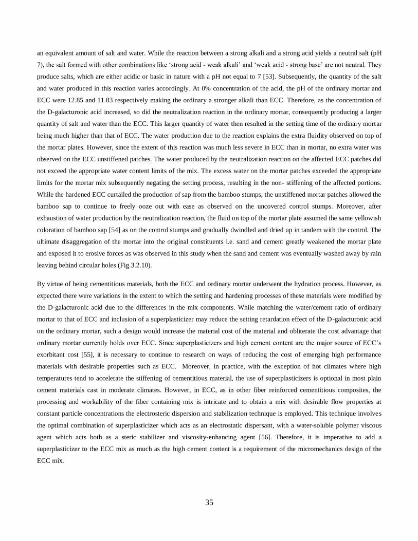
35
an equivalent amount of salt and water. While the reaction between a strong alkali and a strong acid yields a neutral salt (pH
7), the salt formed with other combinations like ‘strong acid - weak alkali’ and ‘weak acid - strong base’ are not neutral. They
produce salts, which are either acidic or basic in nature with a pH not equal to 7 [53]. Subsequently, the quantity of the salt
and water produced in this reaction varies accordingly. At 0% concentration of the acid, the pH of the ordinary mortar and
ECC were 12.85 and 11.83 respectively making the ordinary a stronger alkali than ECC. Therefore, as the concentration of
the D-galacturonic acid increased, so did the neutralization reaction in the ordinary mortar, consequently producing a larger
quantity of salt and water than the ECC. This larger quantity of water then resulted in the setting time of the ordinary mortar
being much higher than that of ECC. The water production due to the reaction explains the extra fluidity observed on top of
the mortar plates. However, since the extent of this reaction was much less severe in ECC than in mortar, no extra water was
observed on the ECC unstiffened patches. The water produced by the neutralization reaction on the affected ECC patches did
not exceed the appropriate water content limits of the mix. The excess water on the mortar patches exceeded the appropriate
limits for the mortar mix subsequently negating the setting process, resulting in the non- stiffening of the affected portions.
While the hardened ECC curtailed the production of sap from the bamboo stumps, the unstiffened mortar patches allowed the
bamboo sap to continue to freely ooze out with ease as observed on the uncovered control stumps. Moreover, after
exhaustion of water production by the neutralization reaction, the fluid on top of the mortar plate assumed the same yellowish
coloration of bamboo sap [54] as on the control stumps and gradually dwindled and dried up in tandem with the control. The
ultimate disaggregation of the mortar into the original constituents i.e. sand and cement greatly weakened the mortar plate
and exposed it to erosive forces as was observed in this study when the sand and cement was eventually washed away by rain
leaving behind circular holes (Fig.3.2.10).
By virtue of being cementitious materials, both the ECC and ordinary mortar underwent the hydration process. However, as
expected there were variations in the extent to which the setting and hardening processes of these materials were modified by
the D-galacturonic acid due to the differences in the mix components. While matching the water/cement ratio of ordinary
mortar to that of ECC and inclusion of a superplasticizer may reduce the setting retardation effect of the D-galacturonic acid
on the ordinary mortar, such a design would increase the material cost of the material and obliterate the cost advantage that
ordinary mortar currently holds over ECC. Since superplasticizers and high cement content are the major source of ECC’s
exorbitant cost [55], it is necessary to continue to research on ways of reducing the cost of emerging high performance
materials with desirable properties such as ECC. Moreover, in practice, with the exception of hot climates where high
temperatures tend to accelerate the stiffening of cementitious material, the use of superplasticizers is optional in most plain
cement materials cast in moderate climates. However, in ECC, as in other fiber reinforced cementitious composites, the
processing and workability of the fiber containing mix is intricate and to obtain a mix with desirable flow properties at
constant particle concentrations the electrosteric dispersion and stabilization technique is employed. This technique involves
the optimal combination of superplasticizer which acts as an electrostatic dispersant, with a water-soluble polymer viscous
agent which acts both as a steric stabilizer and viscosity-enhancing agent [56]. Therefore, it is imperative to add a
superplasticizer to the ECC mix as much as the high cement content is a requirement of the micromechanics design of the
ECC mix.
36
b.Effect on strength
Due to the presence of fibers, the flexural strength of all ECC samples was higher than the mortar samples for all the
conditions tested while the compressive strength of the mortar is higher than that of ECC due to the higher sand content in
mortar. However, for each material, there were some notable variations in both flexural and compressive strength of the
samples curing or soaked in the acid and the samples in water. The attainment of strength of both ECC and mortar was
slightly affected by the presence of D-galacturonic acid in the curing water. As shown in Fig.3.2.3 and Fig.3.2.4, the flexural
and compressive strength of the mortar prisms curing in water was initially higher than that of mortar curing in water
containing D-galacturonic acid. However, the 28day-strength of the mortar cured in acid was slightly higher than that cured
in water. At early ages of the curing process the hydration of the mortar was retarded by the acid to a slightly larger extent
than the ECC. Hence, the delay in strength development of this mortar resulted in a denser and more uniform structure which
attained slightly higher 28-day strength than the mortar cured in pure water (Jumardurdiyeva 2005). Apart from the slight
increase in the flexural strength of ECC curing in water over that curing in the acid-containing water at the age of 2 days,
there was no significant variation in both the flexural and compressive strength of ECC over the 28 days of curing in either
medium. According to Neville (1996), the speed of setting and the rapidity of hardening (strength gain) are independent of
one another. Moreover, the curing process commenced 24 hours after casting when the setting of the plates had already
expired and strength development was commencing. In addition, due to the slow rate of penetration of deteriorative agents,
the impact of the acid on the 40mm thick prisms was much reduced and decreased with increase in age of the plates.
Consequently, as shown in Fig.5 and Fig.3.2.6, D- galacturonic acid did not have any significant effect on both the flexural
and compressive strength of both hardened ECC and mortar after 28 days of water curing. At the age of 28 days when the
hardened samples were soaked in the acid, significant hydration had already transpired. While in general, strong acids with a
pH value below 5.5 can severely decompose cementitious materials [32], the pH of the D-galacturonic acid aqueous solution
used for soaking the mortar samples was only 6.6 and hence not strong enough to inflict significant deterioration.
Whilst there was no significant impact on the flexural and compressive strength of both materials due to D-galacturonic acid,
the impact on the setting of mortar cannot be ignored. The increase in the setting time of ordinary mortar impairs early age
performance of the related structure and exposes the affected sections to erosive agents such as water. Even though other
parts of the structure may set and harden at the expected rates, the eroded sections become conduits for more deteriorative
agents and impinge on the long term durability of the structure [39]. Since ECC is able to maintain its flexural superiority
over ordinary mortar despite the encounter with the acid and can significantly resist retardation of the setting process, ECC
remains a superior material over ordinary mortar in repair and retrofit applications where the flexibility and ductility of ECC
is desirable and ECC structures set up in areas susceptible to organic acids intrusion will have better early performance and
consequently higher long term durability than ordinary mortar structures.

37
3.3.5. Conclusion
1. D- galacturonic acid is an ‘acid -sugar’ with both carbonylic and carboxylic functions. As such, it can retard the setting
time of cementitious materials by the neutralization alkali-acid reaction as well as by retardation of the hydration process
through adsorption of particles on the surfaces of the hydrating cement particles.
2. The retardation in the setting time of ECC was less severe than in ordinary mortar due to the impact of the acidity of its
chemical additives on the pH of the material.
3. The tenacity of ECC towards setting retardation by the D-galacturonic acid allows the hydration process to cause the
necessary stiffening and gain of strength of the material within the expected period. This ensures both short and long term
durability of the overall structure.
4. In environments susceptible to the acid exposure, the retardation of the setting time of ordinary mortar by the D-
galacturonic acid creates points of weaknesses within the overall structure which are vulnerable to deteriorative agents. This
phenomenon depreciates both the short and long term durability of the overall structure.
5. D-galacturonic acid has an insignificant effect on the attainment of flexural and compressive strength of ECC during
curing but it has an appreciable effect on the strength attainment of mortar.
6. There is no significant effect of D-galacturonic acid on the strength of both ECC and mortar after the standard curing
period of 28days, a period in which significant hydration will have transpired in cementitious materials.
7. ECC is able to maintain its flexural superiority over ordinary mortar despite the presence of D-galacturonic acid.
8. The severity of the effect on the hydration process by D-galacturonic acid depends on the material composition of the
structure in question, pH of the reactants and the stage in the hydration process at which the encounter occurs. Moreover
since the content of D-galacturonic acid varies from plant to plant, it is recommended to ascertain the actual composition in a
plant or weed whose sap is likely to get into contact with fresh or hardened cementitious materials. Where necessary,
curtailment of the production of the detrimental sap by an appropriate treatment method before construction should be
undertaken.

38
3.3 EFFECT OF CYCLIC LOADS ON THE SURFACE PROFILE OF ECC LINING
3.3.1. Introduction
An open channel is medium in which a liquid flows with a ‘free surface’ which is defined as the interface between the
moving liquid and an overlying fluid at a constant pressure [57] with water and air being the most common liquid and fluid
respectively. Both natural open channels such as rivers, streams and rivulets or artificial ones such as irrigation canals and
storm –water drains tend to have a wide variability in magnitude, shape and roughness. However, since a free surface exists
in the liquids flowing in all these channels, their flows are governed by the same laws of fluid mechanics [58]. Essentially, all
open channels have a bottom slope and the prime motivating force for liquid flow is gravity. As such, the mechanism of the
flow can be simulated to the movement of a mass body down a slope due to gravity. Basically, the component of the weight
of the liquid along the slope acts as the driving force while the boundary resistance at the perimeter of the channel acts a
resisting force [59].On the other hand, the component of the liquid perpendicular to the slope of the channel exerts a
downward load on the surface of the channel which is usually lined to enhance the stability and vitality the channel.
Moreover, a sub-surface drain may be inserted in the foundation of the open channel to separate groundwater from surface
water and avoid the build-up of water pressure which can damage the channel lining [60]. Types of sub-surface drains
include porous concrete, crushed stone and river gravel [62]. In line with Newton’s laws of motion [61], interactive loads are
expected at the lining/sub-surface drain interface. Essentially, it is desired that after the expiration of these loads, the surface
of the open channel must remain stable, water tight and smooth so as to continually satisfy the key performance requirements
that govern supply, hydraulics, durability and structural integrity [63] and ensure timely and adequate supply of liquids to
intended destinations.
Basically, while the selection of a suitable lining material is governed by both structural integrity and economic viability, the
interaction between the sub-surface drain and lining in response to imposed loads needs to be fully understood to avoid
durability and structural failures. Failures emanate from various causes which include uncertainties in loading, deficiencies in
construction materials, inadequacies in design and poor maintenance [64] and often culminate in high or infinite cost to
economies and human life [65] due to abortion of crops and flooding among other problems. Despite efforts at design stage
to account for all expected loads and predict material behavior, deviations are inevitable during the life time of the open
channel. For instance, flooding, human traffic or light machinery used for maintenance can impose extra loading. Moreover,
loading may actually be cyclic in tandem with irrigation cycles or differential in response to differential settlements in
expansive soil foundations. When the open channel is loaded, the point of contact of the load is the lining which transfers the
load to the channel foundation through the sub-surface drain. While the surface of a porous concrete sub-surface drain is
normally smooth, it is difficult to achieve smoothness on the surface of the crushed stone drain due to some protruding sharp
edges of the stones. While the transferred load may be uniformly distributed, there may be upward reaction loads on the
lining/subsurface drain interface. For instance, if the sub-surface drain comprises crushed stone, the protruding sharp edges
of the crushed stones become pin loads that exert isolated upwards forces onto the lining. Depending on the size of the
crushed stone, magnitude and frequency of imposed downwards load, cycles of the upward pin loads may eventually cause
the lining material to deform in conformation with properties of the constituent lining material and configuration of the

39
foundation. It is imperative that deformations minimize surface roughness of the lining surface since according to Manning or
Chezy [66], an increase in roughness causes a decrease in the velocity of water flowing across a surface. Defined as a
measure of the texture of a surface, roughness is quantified by the vertical deviations of a real surface from its ideal form and
determines the amount of frictional resistance a liquid experiences as it flows through a surface.
While plain concrete is the most commonly used lining material owing to its low cost and easy handling [67], the material
has inherent deficiencies related to its material structure which diminish both its early age performance and long term
durability [68].The brittleness of plain concrete causes it to respond to excessive stress by developing through cracks which
are apt to expansion, allowing the ingress of aggressive agents which cause further deterioration of the open channel [69].
Moreover, the sections between the cracks are prone to both lateral and vertical displacement in response to consecutive
loading or differential settlements in the foundation. On the other hand, deteriorations also increase the roughness of the open
channel lining.
Efforts to address some of the shortcomings of concrete, have led to the development of fiber reinforced materials in recent
years [12]. High Performance Fiber Reinforced Cementitious Composites (HPFRCC) such as Engineered Cementitious
Composites (ECC) exhibit excellent crack dispersion capacity and high ductility. With a strain capacity approximately 350
times that of normal concrete or other fiber reinforced concrete, ECC can achieve maximum ductility in excess of 3% under
uni-axial loading[67][31]. While concrete has been in use since the 19th century [36], ECC was only developed in the 1990s
[37] and hence research is still ongoing to validate wider applicability of the material. In view of the foregoing, this study
sought to clarify the interaction of ECC linings under load with various foundation configurations.
3.3.2. Experimental program
ECC lining surfaces were monitored for variations in roughness and crack development. Three sub-surface conditions were
investigated i.e. compacted soil, crushed stone and crushed stone with a separator inserted between the ECC lining/crushed
stone interface. The roughness of the lining and crack development were assessed by monitoring the levels on fixed nodes on
each surface and the progression of crack widths respectively. To simulate the fluctuations of actual loading during cycles of
flow, the samples were subjected to cyclic loading.
3.3.2.1 Materials
ECC premix powder was used for the lining material while sandy soil, 20mm angular crushed stone and a geo-textile
separator (Tts-101 Toa filter) were used for the foundation. The premix comprised cement, sand, fly ash and PVA fiber
12mm in length, 0.04mm in diameter, 1690MPa in tensile strength and 40,600MPa in modulus of elasticity. The proportions
of the mix components are shown in Table 3.1. An ECC paste was prepared by adding the premix ECC powder and water
containing 3 admixtures namely type A (poly carboxylic acid based superplasticizer), type B (CSA type anti-shrinkage agent)
and type C (poly oxi-alkaline based expansive agent for air content adjustment) to an electric mixer. The room temperature
was kept at 20oC throughout the mixing stage. The mixer was covered and run for 2 minutes soon after addition of water to
avoid losses of the finer components of the mix. While the mixer was running, its cover was removed and mixing was

40
continued until 10 minutes elapsed. The ECC paste was then transferred onto a tray and the homogeneity of the fresh mix
was corroborated through hand mixing and any identified lumps discarded.
3.3.2.2 Testing Procedure
Samples M1, M2 and S1 were prepared in 250mm x 250mm x 50mm forms as detailed in Fig.3.3.1. Each sample comprised
5 units detailed in Table 3.3.1 according to subjected loading. A 40mm foundation was prepared on the base of each form.
The crushed stone in samples M1 and M2 was vibrated for 2minutes to eliminate voids while the sandy soil in sample S1 was
compacted to 90% standard compaction which is the minimum compaction recommended for open channel embankments
[70]. The ECC paste was poured over the foundation to form a 10mm thick lining. A 250mm x 250mm geo-textile was
embedded in between the crushed stone and lining in sample M2. The 250mm x 250mm dimensions were selected to fit the
size of the head used for loading while the 10mm lining thickness corresponds to the minimum thickness of ECC that can be
applied using direct spraying methods [27]. After pouring the ECC paste, the samples were then covered with cotton mats
and cured by sprinkling water every day for a period of 28 days. After the curing period, a grid comprising 50mm x 50mm
units was drawn on the surface of each lining creating a total of 25 nodes. The vertical lines were labeled from left to right as
A to E while the horizontal lines were labeled from top to bottom as 1 to 5 as shown in Fig.3.3. 2.
An automatic leveling device was used to measure the levels on each of the 25 nodes while a crack viewing device was used
to monitor surface cracks. Initial level and crack width readings were taken after which a 220mm x 220mm loading head was
used to apply uniform stress onto the surface of the lining. Each sample was subjected to 4 loading cycles of stress values
described in Table 3.7. Level measurements were taken on the nodes after each loading cycle and the condition of the surface
monitored for crack development. In order to avoid loss of water to the atmosphere and consequent shrinkage, the samples
were kept covered with polythene sheets in an enclosed room throughout the study. In addition, to eliminate contraction and
expansion of the samples due to thermal stresses, the room temperature was kept at 20oC.
The compressive and flexural strength of the ECC mix used in this study were determined by casting standard ECC prisms of
dimensions 40 mm x 40 mm x 160 mm and water curing them at 20oC for 28days after which the strength tests were carried
out. All compressive strength tests adhered to the ASTM C349-02 standard while the flexural strength tests were carried out
in accordance with the ASTM C348-02 standard.
Table 3.7 Description of samples and loads applied
load(t) stress (kPa) sample M1 sample M2 sample S1
0 0 M1-0 M2-0 S1-0
1 21 M1-1 M2-1 S1-1
2 41 M1-2 M2-2 S1-2
3 62 M1-3 M2-3 S1-3
4 83 M1-4 M2-4 S1-4

41
Fig.3.3.1.Description of samples used in this study
1 A B C D E
2
3
4
5
Fig.3.3.2.Gridlines on the surface of each sample
3.3.3. Results and Discussion
The data from the line A3 –E3 marked on Fig.3.3.2 was selected for analysis in this study since it is central and hence free
from the influence of the edges. No cracks were observed on any of the samples after each loading cycle. From Newton’s
laws of motion, the upward reactionary load generated was equal and opposite the maximum applied load of 83kPa shown in
Table 3.7. Therefore, since the first crack stress of ECC is 2.5MPa [71], the stress due to the pin loads was not sufficient to
cause cracking. The surface profiles of the samples after each loading cycle are shown in Fig.3.3.3, Fig.3.3.4 and Fig.3.3.5
which represent samples M1, M2 and S1 respectively. In these figures, the initial profile and the profiles after the 1st, 2
nd, 3
rd
and 4th loading cycles are represented by graphs C-0, C-1, C-2, C-3 and C-4 respectively. These graphs show variations in the
surface profile of the lining in both the lateral and vertical directions. A positive level represents a compaction from the
original surface while a negative level represents a protrusion. Basically, it can be seen that there was no variation in both the
lateral and vertical surface profiles on samples M1-0, M2-0 and S1-0 throughout the experiment. This behavior was expected
since these samples were not loaded. Moreover, these results indicate that influences due to temperature changes and loss of
water to the atmosphere were effectively curtailed. From graph C-0 from each sample, it can be seen that the initial surface
profiles of the linings were not totally level. While it was desirable to achieve a level surface at the casting stage of ECC [72],
10mm ECC lining
crushed stone foundation
(sample M1)
crushed stone foundation with geo-textile separator
(sample M2)
compacted soil foundation
(sample S1)
50mm
50mm
Line A3-E3

42
the viscosity of ECC due to presence of PVA fibers [73] presented a challenge to achieving a smooth surface. The variations
in the lateral and/or vertical surface profiles after each loading cycle are detailed below:
a.ECC lining on crushed stone foundation (sample M1)
From the graphs for the lining cast directly on crushed stone i.e. samples M1-0 to M1-4, it can be seen that while there was
no significant change in the lateral profile of an individual sample with each loading cycle, a systematic pattern in the vertical
displacement of the linings was observed. The surface levels generally increase with increase in cycles. Since an increase in
the reduced level value indicates a compaction, the results show that the lining/crushed stone unit compressed with each
loading cycle. Characteristically, it is impossible to totally eliminate voids in uniform size crushed stone despite prior
vibration. As a result the repacking of the crushed stones into existing voids in response to the applied load resulting in the
compaction. Even though the loading was in the vertical direction only, the lining was free to move laterally and curve
upwards since it was floating in the form. However, the graphs show insignificant variations in the lateral profile. This means
that even though the crushed stone foundation beneath the lining comprised loose stones, the lining/foundation unit actually
displaced vertically as a single unit. It is thought that at casting stage, due to the capability of ECC to flow under its own
weight and fill in the form work in a process termed ‘self compactibility’[74] , the fresh ECC flowed and filled the voids
within the crushed stone. Upon solidification, an ECC/crushed stone composite was created which destroyed the ECC
lining/crushed stone interface and rid the foundation surface of undulations due to the sharp edges of the stones. As a result,
the scattered pin loads due to stone protrusions were eliminated and no upward reactionary pin loads and consequent
undulations were generated in response to applied loading. Even though the compressive strength of the ECC used in this
study was 32kPa, the ECC lining withstood stresses of 62kPa and 83kPa since infusion of the crushed stone into the ECC
paste created a composite with a higher compressive strength [74]. As a result no signs of failure were observed on the
surface of the lining even for the stresses beyond the compressive strength of ECC.
b.ECC lining on compacted soil foundation (sample S1)
After the first loading cycle, the lateral profile of the ECC lining cast on compacted soil flattened out and maintained the
same levelness with consecutive cycles. Unlike the ECC paste cast over crushed stone which flowed into the pores within the
crushed stone and created an ECC/crushed stone composite, the ECC lining and compacted soil remained separate layers
after solidifying. As a result, the lining could alter its lateral profile and flatten out in response to the first load. On the other
hand, as in sample M1, a systematic pattern in the vertical displacement of the linings for sample S1 due to compaction of the
surface was observed. However, the magnitude of the vertical displacements did not differ significantly from those of
samples M1. Whilst sandy soil was expected to undergo higher compaction due to relatively lower densities to stone [34], the
initial application of 90% compaction level and the presence of voids in the crushed stone moderated the compactibility of
the 2 materials. The high compaction level applied to soil decreased its porosity. In practice such a configuration is not
recommended since the material underlying the lining cannot drain away groundwater and will cause a build-up of ground
water pressure and ultimate damage to the lining.

43
c.ECC lining on crushed stone foundation with geo-textile separator (sample M2)
The behavior of the lining cast on crushed stone with a geo-textile separator embedded in between was similar to that of
sample S1 for the lower loads of 21kPa and 41kPa but the pattern significantly deviated for the higher loads. In this case, the
geo-textile separator attached itself to the ECC paste and acted as barrier which prevented the ECC paste from flowing into
the crushed stone pores. Therefore, like in the sample S1, the ECC lining and the crushed stone foundation remained separate
after solidifying. Consequently, the first loading cycles only flattened out samples M2-1 and M2-2 and the lateral profile
levelness was maintained with consecutive loading cycles as in samples S1-1 and S1-2. Moreover, as in samples S2-1 and
S2-2, the levels in samples M2-1 and M2-2 generally decreased after application of the first loading cycle. It is thought that
since both samples M2 and samples S1 remained as separate layers after solidifying, the lining separated itself from the
compacted soil as it flattened out resulting in a protruded surface and consequent decreased levels. However, a marked
deviation in behavior from sample S1 was observed with application of the 62kPa loading. The ECC lining in sample M2-3
responded by deforming into an undulating profile as shown in Fig.3.3.4. Since the undulations match the surface profile of
the crushed stone foundation, it is thought that the angular edges of the crushed stone exerted upward pin loads onto the geo-
textile attached to the ECC lining. Being flexible, the geo-textile subsequently transferred the loads to the ECC lining
resulting in the deformation. However, the deformations that occurred were within the elastic limits of the ECC such that
total recovery occurred after each loading cycle [74] allowing recurrence of the undulations. This notion is further confirmed
by the magnitude and wavelength of the undulating surface which remained almost constant for all the loading cycles. In
practice, undulations increase the roughness of open channel linings. Increase in roughness is undesirable since it culminates
in flow losses in accordance with the Manning’s or Chezy’s formulae [76]. The consequent decrease in the quantity and rate
of water delivered to a desired point disrupts irrigation cycles and other water supply systems. However, since the crushed
stone used in this study was only 20mm, the amplitude of the undulations was restricted to less than 5mm and may not
significantly affect the roughness of the open channel lining. Nevertheless, it is likely that roughness will significantly
increase if larger sizes of crushed stone are used in the subsurface drain with ECC as the open channel lining due to the high
strain capacity and ductility of ECC [76] which gives the material flexibility to stretch to high magnitudes. Despite the
occurrence of undulations on M2-3, no cracks were observed since the magnitude of the generated upward reactionary loads
of 62kPa was not high enough to cause cracking of sample M2-3. Moreover, it is believed that the geo-textile that can also
act as reinforcement absorbed some of the loads.
Finally, at applied loading of 83kPa which was much higher than the strength of the ECC, the lining lost its ductility and
neither undulations nor lateral profile variations were observed on sample M2-4. Rather, the lining underwent increased
compaction as the cycles increased due to repacking of the crushed stone as observed in samples M1 and S1.

44
Fig. 3.3.3.Surface profile along line A3-E3 of ECC lining cast on crushed stone (sample M1)
M1-0
-4-3
-2-101
234
5678
910
0 50 100 150 200
Node(mm)
Level(m
m)
C-0 C-1
C-2 C-3
C-4
M1-1
-1
0
1
2
3
4
5
6
7
8
9
10
0 50 100 150 200
Node(mm)
Level(m
m)
C-0 C-1
C-2 C-3
C-4
M1-2
-3
-2
-1
0
1
2
3
4
5
6
7
8
9
10
0 50 100 150 200
Node(mm)
Level(m
m)
C-0 C-1
C-2 C-3
C-4
M1-3
-4-3
-2-1
01
23
45
67
89
10
0 50 100 150 200
Node(mm)
Level(m
m)
C-0 C-1
C-2 C-3
C-4
M1-4
-5-4-3-2-10123456789
10
0 50 100 150 200
Node(mm)
Level(m
m)
C-0 C-1
C-2 C-3
C-4

45
Fig.3.3.4.Surface profile along line A3-E3 of ECC lining cast on crushed stone with a geo-textile embedded (sample M2)
M2-0
-6-5-4-3-2-10123456789
10
0 50 100 150 200
Node(mm)
Level(m
m)
C-0 C-1
C-2 C-3
C-4
M2-1
-5-4-3-2-10123456789
10
0 50 100 150 200
Node(mm)
Level(m
m)
C-0
C-1
C-2
C-3
C-4
M2-2
0
1
2
3
4
5
6
7
8
9
10
0 50 100 150 200
Node(mm)
Level(m
m)
C-0 C-1
C-2 C-3
C-4
M2-3
-5-4-3-2-10123456789
10
0 50 100 150 200
Node(mm)
Level(m
m)
C-0 C-1
C-2 C-3
C-4
M2-4
-3
-2
-1
0
1
2
3
4
5
6
7
8
9
10
0 50 100 150 200
Node(mm)
Level(m
m)
C-0 C-1
C-2 C-3
C-4

46
Fig.3.3.5.Surface profile along line A3-E3 of ECC lining cast on compacted soil (sample S1)
S1-0
-1
0
1
2
3
4
5
6
7
8
9
10
0 50 100 150 200
Node(mm)
Level(m
m)
C-0 C-1
C-2 C-3
C-4
S1-1
-3
-2
-1
01
2
3
4
5
67
8
9
10
0 50 100 150 200
Node(mm)
Level(m
m)
C-0 C-1
C-2 C-3
C-4
S1-2
0
1
2
3
4
5
6
7
8
9
10
0 50 100 150 200
Node(mm)
Level(m
m)
C-0
C-1
C-2
C-3
C-4
S1-3
-2
-1
0
1
2
3
4
5
6
7
8
9
10
0 50 100 150 200
Node(mm)
Level(m
m)
C-0 C-1
C-2 C-3
C-4
S1-4
0
1
2
3
4
5
6
7
8
9
10
0 50 100 150 200
Node(mm)
Level(m
m)
C-0 C-1
C-2 C-3
C-4

47
3.3.4. Conclusion
1. Cyclic loads affect the vertical profile of the ECC lining cast on both crushed stone and compacted soil by
compacting the surface. The level of compaction depends on the compactibility of the foundation components.
2. The effect of cyclic loads on the lateral profile of the ECC lining depends on the composition of the underlying
subsurface drain. Cyclic loads do not affect the lateral profile of the ECC lining cast directly on a crushed stone
drain. ECC paste can flow and solidify in the crushed stone voids, resulting in an ECC/ crushed stone composite
with a higher compressive strength than the originally designed ECC lining. However, the solidification clogs the
voids in the crushed stone and diminishes its function as a drain culminating in damage to the lining due to a build-
up of ground water pressure.
3. The inclusion of a geo-textile separator between the crushed stone subsurface drain and the ECC lining has a
significant impact on the response of the ECC lining to cyclic loads. The geo-textile effectively separates the
subsurface drain from the lining and allows the lining to deform freely. By preventing the ECC paste from clogging
the crushed stone pores and diminishing the capacity of the subsurface drain the geo-textile prevents the build-up of
ground water pressure. In addition, the geo-textile also prevents the occurrence of cracks on the ECC lining by
moderating the upward pin loads from the crushed stones in the foundation.
4. Cyclic loads do not affect the lateral profile of the ECC lining cast on compacted soil foundation. The lining and the
subsurface also remain as separate layers after solidification allowing it to displace freely. However, the absence of a
freely draining material below the ECC lining will cause damage to the lining due to build-up of ground water
pressure.
5. Whether it is used with or without a geo-textile, the ductility of ECC enables it to respond to excessive loads by
stretching like metal rather than breaking like concrete. Being flexible, ECC can assume the shape of the underlying
foundation material and develop undulations. While undulations due to small sizes of crushed stone cannot
significantly increase surface roughness of a water channel, larger undulations can cause significant increases which
consequently increase Manning’s roughness coefficient and decrease the velocity of flow across a surface.
6. The characteristic high strain capacity of ECC enables it to restrict the crack widths in linings to less than 0.1mm
and satisfy serviceability limits in water storage facilities where according to British Code BS 8007(1987) [ref.
10.19] a maximum crack width of 0.2mm is deemed necessary for maintaining water tightness.

48
3.4. EFFECT OF PLATE THICKNESS ON CRACK PROPAGATION CHARACTERISTICS OF ECC
3.4.1. Introduction
Plain cement materials such as cement pastes, mortars and concretes are commonly used for construction. In spite of their
ubiquity, these materials have several inherent deficiencies such as brittleness originating from their material structure [77]
which diminish both early age performance and long-term durability. Modern concepts of fiber reinforcement and interface
engineering emanated from efforts to address the deficiencies of these materials [82] producing High Performance Fiber
Reinforced Cement Composites (HPFRCC) such as Engineered Cementitious Composites (ECC) in the 1990s [47]. ECC is a
ductile fiber reinforced cement based composite material that has been found to be excellent at crack dispersion. Formed
primarily from cement and sand with fiber and certain chemicals as additives, ECC is systematically engineered to achieve
high ductility under tensile and shear load. It can achieve maximum ductility in excess of 3% under uniaxial loading with
only 2% volume of fiber content [10]. Moreover, due to its strain hardening capacity, ECC develops fine cracks of less than
0.1mm width, which are limited to the surface in contrast to the through cracks developed by plain cement materials [31].
Durability concerns of plain cement materials also exist in retrofit or repair works especially on the substrate/repair layer
interface. In some cases, the drying shrinkage of the new material restrained by the old material leads to cracking and
interface de-lamination introducing water and other deteriorative agents into the repaired system thereby invoking fresh
deterioration and necessitating a new and certainly uneconomical repair cycle. However, it has been verified experimentally,
that when an adequate bond is provided, the high ductility of ECC can relieve shrinkage induced stresses in the ECC repair
layer and at the ECC/concrete interface, suppressing the development of large through cracks and interface de-lamination
[68]. Therefore, in retrofit and repair applications, based on properties only, ECC is a more suitable material than traditional
plain cement materials. However, in practice, the use of ECC is currently limited to less than 10 countries worldwide. This is
mainly due to its elevated cost emanating from its requirement of special fibers, very high cement content and a high
performance super-plasticizer [55]. Certainly, cost and sustainability of ECC are two aspects that need to be addressed to
make the use of ECC widely acceptable. While optimization of the composite to minimize the fiber content is critical to cost
reduction, optimization of the overall dimensions of ECC elements can reduce the volume of material required thereby
reducing the overall material cost.
In repair and retrofit applications, there is usually little flexibility regarding the length and width of the original structure but
thickness tends to be adjustable depending on the structural requirements. Even though it is possible to apply ECC layers of
thickness as low as 10mm using the direct spraying method [27], the selection of the optimum thickness for a particular
element depends on the structural requirements such as expected crack widths since design codes specify crack width limits
based on functional use of the structure. For instance, the British Code BS 8007(1987) [ref. 10.19] states that a maximum
crack width of 0.2mm is deemed adequate for water tightness in water retaining structures, and a more stringent 0.1mm is
necessary where aesthetic appearance is of particular importance. Hence, it is imperative for a repair layer to meet this
standard to be deemed adequate. Inevitably, variations in material content, dimensions and external loads in turn vary the size
and distribution of cracks developed by any material. It is therefore the objective of this study to elucidate the impact of
variations in thickness, on the size and distribution of cracks propagated by ECC.

49
3.4.2. Experimental Program
Repair and retrofit structures are usually applied in layers or plate-like elements and hence in this study, plates were used as
the target elements. ECC plates of varying thickness were cast and cracks artificially generated followed by the determination
of crack width and crack density.
3.4.2.1 Materials
ECC premix powder was used in this experiment. The major components of the ECC premix powder were cement, sand and
water soluble poly-vinyl alcohol (PVA) fiber of length 12mm, diameter 0.04mm, tensile strength 1690MPa and modulus of
elasticity 40,600MPa. The mix proportions of ECC are shown in Table 3.1. At a room temperature of 20oC, the premix ECC
powder was added to an electric mixer. Water and 3 admixtures: Type A (super-plasticizer), Type B (anti-shrinkage agent)
and Type C (expansive agent for air content adjustment) were mixed together and added to the premix powder. The mixer
was covered and run for 2 minutes to avoid losses of the mix components. While the mixer was running, its cover was
removed and mixing was continued until 10 minutes elapsed. The ECC paste was then transferred into a tray. The
homogeneity of the mix was further corroborated by hand mixing.
3.4.2.2 Experimental Procedure
a. Determination of Crack Distribution
ECC plates of dimensions 400mm x 400mm and thicknesses of 10mm, 20mm, 30mm were cast and cured in water for
28days at 20oC. The dimensions 400mm x 400mm were selected to fit the limits of the device used for generation of cracks.
The upper dimension of 30mm was selected since it is the common thickness used in ECC repair applications while the lower
dimension of 10mm coincides with the minimum ECC thickness that can be placed using the direct spraying technique.
Three sets of ECC plates were prepared for each thickness, each set comprising 3 plates. Using the ‘Third-Point Loading’ test
configuration [76], on a bending machine, the first set was loaded to ultimate failure to determine the average ultimate failure
load for each thickness. Using 80% of the determined average ultimate failure load, cracks were generated on the second set.
The third set was kept intact as the control. A 100mm wide strip was marked on the central portion of the set of plates with
cracks. A thin film of fluorescent paint was used to accentuate the cracks and in a dark room, each plate was illuminated
under black light, which caused the fluorescent paint-packed cracks to glow yellow. Using a digital camera, pictures were
taken at 3 positions on the strip. Images from the camera were viewed using the computer-aided drafting software, AutoCAD
2002. The number of cracks along the 100mm wide strip was then physically counted from the images and multiplied by 10
to obtain the average number of cracks per unit meter.

50
b. Determination of Crack Width
Crack widths were measured using a crack width-measuring device, the Crack Viewer FCV-30. The average crack width was
determined by taking measurements on 3 cracks from each of the 10mm, 20mm and 30mm plates used for determination of
crack distribution. Images and data of each crack were recorded as shown in Fig.3.4.1.
3.4. 3. Results and Discussion
Table 3.8 Average crack density and crack width
thickness average density average crack width
(mm) (cracks/m) (mm)
10 125 0.07
20 115 0.08
30 135 0.08
During mixing of the material, it was observed that the ECC fresh mix had very high workability, which enabled easy placing.
The behavior of the 10mm, 20mm and 30mm plates under load was similar to ductile material i.e. gradual bending into a
visible curve in contrast to instant rupture of plain cementitious materials. Moreover, multiple fine surface cracks were
observed on the surface of the plates. As shown in Table 3.8, the average crack widths for the 10mm, 20mm and 30mm plates
were 0.7mm, 0.8mm and 0.8mm respectively while the average crack densities were 125 cracks/m , 115 cracks/m and 135
cracks/m.
The crack widths and crack densities obtained in this research agree with data obtained by previous researchers. For instance,
the multiple fine surface cracks observed on the ECC plates are typical and the values of crack widths of 0.8mm to 0.9mm
agree with findings by Li [22] and Kanda [27]. The unique property of ECC relative to other fiber reinforced composites is
its ductility and confinement of crack widths to less than 0.1mm.The high workability of ECC is due to the moderate amount
of short discontinuous fibers which allows flexibility in construction execution, including self-consolidation casting [73], a
property that is very useful in repair and retrofit applications. The bending behavior in response to loading is typical ductile
behavior characteristic of ECC enabling failure of ECC structures to be less catastrophic than plain cement structures which
are brittle.
The matrix of fibres evenly distributed within ECC slide within the cement forming matrix cracks when loaded whose
density increase until composite peak load resulting in the bending of ECC under excessive strain. From Table 3.8, there was
no significant variation in crack patterns, crack density and crack width for the 10mm, 20mm and 30mm thicknesses.
Ultimate failure of all the plates was gradual and was preceded by bending in typical ductile behavior. The multiple micro
cracking observed at the crack generation load (80% of ultimate failure load) is due to the characteristic strain hardening after
the first cracking of the ECC. The fibers, which are evenly, distributed within the material bridge the cracks thereby
restricting the crack width. This tight crack width by ECC is self-controlled and a material characteristic independent of rebar
reinforcement ratio [20] or plate thickness. The restriction of crack width to an average size of 0.8mm obtained in this study

51
is important in water storage facilities applications where a maximum crack width of 0.2mm and 0.1mm are deemed
necessary for water tightness and aesthetic appearance respectively. Since the reduction in thickness of the plates does not
significantly affect crack width or crack density, ECC layers of small thickness can be applied in repair and retrofit works
where minimal distortion of the dimensions and aesthetic appearance of the original structure is crucial.
So far, researchers have focused on the crack dispersion properties and structural aspects of ECC and there is very little focus
on the issue of cost reduction which to date has limited the use of an otherwise excellent repair material. While previous
researchers (Kunieda [31]; Swift [78]) have elucidated the effectiveness of ECC as a repair material, the optimization of the
dimensions of ECC elements as a cost reduction measure has not been investigated. While technically it is possible to apply
10mm thick ECC layers, in practice most applications are 30mm thick. This research investigated the reduction in thickness
of ECC repair layer as a material volume reduction and consequent cost cutting measure and proved that it is possible to
decrease the thickness of an ECC repair layer and still obtain its unique and desirable properties of ductility and multiple
surface fine cracks of widths less than 0.1mm. In terms of volume of material, a 10mm reduction in thickness results in a
33% reduction of volume per unit area, which is significant in the reduction of cost of material. This is important in
addressing the current limitation in the use of ECC due to the high cost of the material.
3.4.4. Conclusion
1. The thickness of plates has no significant effect on the crack width and crack distribution on ECC. This enables
smaller thicknesses of ECC elements to be applied where structurally possible, thereby reducing the material volume
and subsequently lowering overall material costs.
2. ECC can restrict crack widths to less than 0.1mm despite reduction in thickness from 30mm to 10mm making ECC
suitable for use in water storage facilities.
3. The ability of ECC to maintain small widths despite reduction in thickness is important for repair and retrofit
applications where adherence to the structural integrity and minimal distortion to aesthetic appearances of the
original structure are crucial.
4. Reduction in thickness of ECC results is significant reduction in the volume and material cost which addresses the
issue of the high cost currently associated with the material. Moreover, the ductility and production of fine surface
cracks as opposed to the brittleness and production of through cracks by plain cementitious material makes ECC a
more durable repair or retrofit material since it curtails the cycle of repairs imminent with the use of other plain
cement materials thereby also increasing economic viability.

52
CHAPTER 4: OVERALL CONCLUSIONS AND RECOMMENDATIONS
1. ECC was found to be more effective than regular concrete in curtailing the re-emergence of weeds on the surfaces of earth
embankments due to its production of fine surface cracks of less than 0.1mm in width. On the other hand, through cracks of
unlimited width produced by concrete are susceptible to further expansion by lateral or vertical movements due to differential
settlement of earth embankments culminating in loss of serviceability. In contrast the use of ECC in the repair of earth dams
or lining of canals improves the serviceability performance.
2. While organic acids are known to retard the setting time of all cementitious materials, retardation effect on ECC was found
to be less severe than in ordinary mortar hence ECC could stiffen and gain of strength within the expected period. However,
the retardation of the setting time of ordinary mortar by the organic acid created points of weaknesses vulnerable to
deteriorative agents and impairing both short and long term durability of related structures. Despite the severity effect of
hydration modification on ECC being less than on mortar, higher concentrations of the acid in certain weeds increase the risk
even in ECC. It is therefore recommended to eliminate sources of organic acids before casting thin layers of all cementitious
materials in applications such as the repair of earth dams and lining of canals.
3. Due to its ductility ECC was found to be apt to deformation by non-uniform loads which caused undulations on the surface
of ECC linings. In canal surfaces such a phenomenon increases roughness. However the significance of the roughness
depends on the magnitude and source of the non-uniform loading. In cases where large size crushed stone is used in the sub-
surface drain, the magnitude of deformation is expected to be large consequently increasing roughness. It is therefore
recommended to use separators such as geotextiles which have been found in this study to moderate the formation of
undulations.
4. The thickness of ECC was found to have no significant effect on the width and distribution of cracks produced by the
material. This means reduction of thicknesses of ECC elements where structurally possible can significantly reduce the
volume of material subsequently lowering overall material costs. This is important since to date the use of ECC is being
limited by its exorbitant cost and there is need to continue to find ways to decrease the cost to make its use more widely
acceptable.
Finally, this study clarified that ECC is a more durable material than traditional concrete such as mortar in earth hydraulic
structures applications. This means the use of ECC in repair can improve the serviceability performance of earth hydraulic
structures. Moreover, despite the relatively high initial cost of the material, ECC curtails the cycle of repairs imminent with
traditional concretes thereby decreasing its Life Cycle Costs (LCC). Therefore, in the long term ECC is a more economically
viable material.

53
REFERENCES
1. United States Geological Survey. “Earth's water distribution”. http://ga.water.usgs.gov/edu/waterdistribution.html,
Retrieved 2011.5.29
2. GreenFacts Website. “Scientific Facts on Water: State of the Resource”. http://www.greenfacts.org/en/water-
resources/index.htm#2, Retrieved 2011.5.29
3. The Constructor.Org. “Earthfill Dams & Its Classification”.Dams, Hydraulic Structures, Water Resources,
http://theconstructor.org/water-resources/earthfill-dams-its-classification/2273/ ,Retrieved 2011.5.29
4. FAO. “Canal lining”, ftp://ftp.fao.org/docrep/fao/010/ai585e/ai585e04.pdf, Retrieved 2011.5.29
5. The Constructor.Org . “Failure of Earthfill Dams”. Dams, Hydraulic Structures, Water
Resources ,http://theconstructor.org/water-resources/failure-of-earthfill-dams/2287/, Retrieved 2011.5.29
6. FEMA 534. “ Impact of Plants on Earthen dams”. Technical Manual for Dam Owners, Sept 2005
7. BS 8007(1987) [ref. 10.19]
8. Thandhaveswara B.S. “Hydraulics”, http://nptel.iitm.ac.in/courses/IIT-MADRAS/Hydraulics/pdfs/ Unit22/22_1.pdf,
Retrieved 2011.5.29
9. Li VC. “Advances in ECC Research”, Advanced Civil Engineering Materials Research Laboratory, Department of
Civil and Environmental Engineering, The University of Michigan, USA
10. Li V.C. “Engineered Cementitious Composites”. Proceedings of ConMat'05, Vancouver, Canada, 2005.p. 22-24
11. University of Michigan News Service.“UM makes bendable concrete”,
www.umich.edu/news/?Releases/2005/May05/r050405. Retrieved 2011.5.29
12. Victor C. Li, Dhanada K Mishra, Hwai-Chung Wu. “Matrix design for pseudo-strain-hardening fiber reinforced
cementitious composites”, Advanced Civil Engineering Materials Research Laboratory, Department Of Civil
Engineering, University Of Michigan, Ann Arbor, MI 48109-2125, USA
13. Kanda T, Tomoe S, Nagai S, Kanakubo T, Shimizu K. “ Full Scale processing Investigation for ECC Pre-Cast
Elements”, Kajima Technical research institute, University of Tsukuba
14. Ohio Department of Natural Resources . “Trees and Brushes”, Dam Safety Fact Sheet # 93-28.2002
15. Coordinator for Disaster Prevention Research. “Repairing method of old earth dam using the muddy soil”.
Department of Planning and General Administration, National Institute for Rural Engineering Publications, 2006
16. Sakai T, Saigusa N, Yamamoto S, Akiyama T. “Microsite variation in light availability and photosynthesis in a cool
temperate deciduous broadleaf forest in central Japan”. The Ecological Research Journal: Springer Japan, 2005;
20:537-545
17. Rao K.K, Hall D.O. “Photosynthesis”, Cambridge University Press, 6th Edition, 1999.p.25
18. Popchenko S.N. “Asphalt membranes for dams of local materials”. Translated from Gidrotekhnicheskoe
Stroitel’stvo 1969; 11:15-18
19. Armstrong W.P. “The power of plants”. Wayne’s Word Noteworthy Plant for 2006
20. Patodi S.C and Rathod J.D. “Advancements in Fiber Reinforced Cementitious Composites - An Overview”,The
Master Builder:India’s Premier Construction Magazine, Retrieved 2011.5.29
21. Li M and Li V.C. “Behavior of ECC/Concrete Layer Repair System Under Drying Shrinkage Conditions”, Journal
of Restoration of Buildings and Monuments, 2006;12(2).p.143-160
22. Li V.C, Dhanada K, Mishra, Hwai-Chung Wu. “Matrix design for pseudo- strain hardening fiber reinforced
composites. Materials and Structures”, 1995(28); 586-595
23. Kunieda M, Rokugo K. “Recent progress of HPFRCC in Japan”. Journal of Advanced Concrete Technology, 2006;
4(1):19-33
24. David F. “The Book of Bamboo”, San Fransisco, 2003.
25. Tanaka K, Pyo S, Miyauchi H. “Development of apparatus for measuring penetration force of rhizome tip to
waterproofing membrane and some measured force on bamboo and lawn grass”, Struct.Constr.Eng., AI 2006;
602:67-71
26. Walters D.R., Keil D.J. “Vascular Plant Taxonomy”, Kendall/Hunt Publishing Company, 1996
27. Kanda T, Saito T, Sakata N, Hiraishi M. “Fundamental properties of direct sprayed ECC”, Proceedings of the JCI
International Workshop on Ductile Fiber Reinforced Cementitious Composites (DFRCC) - Application and
Evaluation (DRFCC-2002), Takayama, Japan, 2002. p. 133-142.
28. Thimijan, Richard W., Heins R.D. “Photometric, Radiometric, and Quantum Light Units of Measure: A Review of
Procedures for Interconversion”. HortScience, 1982; 18:818-822.
29. Griffith A.A. “ Phenomena of rupture and flow in solids”, Philosophical transactions of the royal London society,
Series A containing papers of a mathematical or physical character, 1921; 221:163-198

54
30. Li V.C, “ Reflections on the research and development of Engineered Cementitious Composites”, Proceedings of the
JCI International Workshop on Ductile Fiber Reinforced Cementitious Composites (DFRCC), Application and
Evaluation (DRFCC-2002), Takayama, Japan, 2002.p.1-21.
31. Kunieda M, Rokugo K, Miyazato S. “Structural applications of HPFRCC in Japan”, Measuring, Monitoring and
Modeling Concrete Properties Netherlands: Springer, 2006. p.17
32. Neville A. M. “Properties of Concrete”,John Wiley and Sons, 4th and Final Edition.p.425
33. OhanaY, Miyara M, Endo M. “ Drying shrinkage and strength of steel fiber reinforced mortars containing
shrinkage-reducing agent”. Journal of the Society of Materials Science ,Japan, 34(376) p.14-18
34. Annual Book of ASTM Standards 2004.Section 4(Construction), Volume 04.02, “Concretes and Aggregates”,
C78-02 p.37
35. Repair of Concrete Structures to EN1504- A Guide for Renovation of Concrete: Butterworth-Heinemann p.117
36. Francis A.J .“The Cement Industry 1796-1914: A History” ,1977
37. Li V.C. “From Micromechanics to Structural Engineering – The Design of Cementitious Composites for Civil
Engineering Applications.” J.Struct.Mech.Earthquake Eng.,JSCE,10(2)37-48
38. Lepech M.D., Li V.C. “Long Term Durability Performance of Engineered Cementitious Composites” Journal of
Restoration of Buildings and Monuments,2006,12(2)119-132
39. Panganayi et.al. “Effectiveness of ECC in curtailing re-emergence of weeds on an earth embankment surface”
Construction and Building Materials, 2010,24:545-551
40. Materials Module. “Portland Cement”. http://training.ce.washington.edu/WSDOT/Modules/03_materials/03-
4_body.htm ( Mar.4, 2010)
41. Jumadurdiyeva A, Ozkula M.H., Saglamb A.R., Parlakb N. “The utilization of beet molasses as a retarding and
water-reducing admixture for concrete” Cement and Concrete Research,2005, 35:874-882
42. Lee.G-S et.al . “The beneficial effect of the sap of Acer mono in an animal with low-calcium diet-induced
osteoporosis-like symptoms.” British Journal of Nutrition,2008 ,100, 1011–1018
43. Kleinhenz V, Midmore DJ(2001). “Aspects of Bamboo” Agronomy.In:D.L Sparks.Advances in
Agronomy, USA:Academic press ,74,99-153
44. Liese,W . “The structure of bamboo in relation to its properties and utilization.” Bamboo and its use International
Symposium on Industrial Use of Bamboo. China,1992
45. David F .“The Book of Bamboo.”,1994, San Fransisco
46. Kumar S et al. “Bamboo Preservation Techniques: A Review” International Network for Bamboo and Rattan and
Indian Council of Forestry Research Education. INBAR and ICFRE
47. Li V.C. “On Engineered Cementitious Composites (ECC):A Review of the Material and Its Applications” ,Journal of
Advanced Concrete Technology,2003,1(3):215-230
48. Bitter T, Muir H.M. “A Modified Uronic Acid Carbazole Reaction”, Analytical Biochemistry,1962, 4:330- 334
49. Brooks J.J. et.al. “Effect of admixtures on the setting times of high strength concrete” Cement and Concrete
Composites,2000, 22:293-301
50. Alshamsi A.M., Sabouni A.R.,Bushlaibi A.H. “Influence of set-retarding superplasticizers and microsilica on
setting times of pastes at various temperatures” Cement and Concrete Research,1993, 23(3),592-598
51. Papayianni I et.al.(2005) “Influence of superplasticizer type and mix design parameters on the performance of them
in concrete mixtures” Cement and Concrete Composites ,2005,27:217–222
52. Milestone N. B. “Hydration of tricalcium silicate in the presence of lignosulphonates, glucose, and sodium
gluconate” J.Am ceram.Soc, 1979,62(7-8):321-324
53. Sunil K.S, “Neutralization reaction” http://cnx.org/content/m17138/1.2/ Retrieved Jul.10,2010)
54. Dharmananda S. “Bamboo as Medicine”Institute for Traditional Medicine, Portland, Oregon,
http://www.itmonline.org/arts/bamboo.htm (Mar. 5, 2010)
55. Patodi S.C.and Rathod J.D(2008). “Response of Engineered Cementitious Composites with Steel Reinforcement and
Concrete in Moment Resisting Frames”, New Building Materials and Construction World, 13(12)232-242
56. Fischer ,G et.al.“Design of Engineered Cementitious Composites (ECC) for processing and workability
requirements.” http://ace-mrl.engin.umich.edu/NewFiles/publications/BMC7-Fischer.doc, Retrieved Jul.10,2010
57. Chow V.T. “Open-Channel Hydraulics”, McGraw-Hill, Inc;1959
58. Subramanya K. “Flow in open channels”,3rd
ed. Tata: Mcgraw-Hill; 2009
59. Chaudry M.H. “Open Channel Flow”,2nd
edition. New York:Springer; 2007
60. French H.F. “Farm drainage” .New York: Orange Judd and Company 1859
61. Stuyt L.C.P.M, Dierickx J, Martinez B.J. “ Materials for subsurface land drainage systems” ,FAO Irrigation and
Drainage Paper 60 Rev.1 ISSN 0254-5284 ;2006, p.21
55
62. Browne M.E, “Schaum's outline of theory and problems of physics for engineering and science”, McGraw-Hill
Companies; 1999, p. 58
63. ISO 2394:1998. “General principles on reliability for structures”,3rd
ed. 1998
64. Mark A, Marek P.E. “Hydraulic Design Manual: Conduit strength and durability” ,Texas Department of
Transportation (TxDOT): Design Division (DES), 2009
65. Gharabaghi B, Dickinson W.T, Rudra R.P, Snodgrass W.J , Krishnappan BG. “Performance analysis of reinforced
vegetative channel lining systems”, Computers & Structures 1999;72(1-3):149-164
66. Souders DT, Hirt CW. “Modeling roughness effects in open channel flow”, Flow Science Technical Note (FSI-02-
TN60). Flow Science Inc.;2002
67. Lepech M.D. and Li V.C. “Large-scale processing of Engineered cementitious composites”. ACI Materials Journal
2008; 105(4):358-366
68. Li M, Li VC. “Behavior of ECC/Concrete Layer Repair System Under Drying Shrinkage”, Journal of Restoration of
Buildings and Monuments, 2006;12(2):143-160
69. Minerals Council of Australia. “Minesite Water Management Handbook” .1st ed.1997
70. Li V.C. “Engineered Cementitious Composites(ECC)- Tailored composites through micromechanical modeling”,
Fiber Reinforced Concrete: Present and the Future, Eds: N. Banthia, A. Bentur, and A. Mufti, Canadian Society of
CivilEngineers, 1998.
71. Kamada T and Li VC. “The effects of surface preparation on the fracture behavior of ECC/concrete repair system”.
Cement & Concrete Composites , 2000;22:423- 431
72. Saxena S.K. “Polyvinyl Alcohol (PVA)”. Chemical and technical assessment(CTA) , FAO 61st JECFA, 2004
73. Kong H.J., Bike S, Li VC. “Development of a self-compacting ECC employing electrosteric
dispersion/stabilization”, J. Cement and Concrete Composites,2003;25(3):301-309
74. Neville AM. Properties of Concrete, 4th ed. John Wiley and Sons;1996
75. Fisher G and Li V.C . “Deformation Behavior of Fiber Reinforced Polymer Polymer reinforced Engineered
Cementitious Composites Under reversed cyclic loading conditions”. ACI Structural Journal 2003;100(1): 25-35
76. ASTM C78-02, 2004. “Standard Test Method for Testing Flexural Strength of Concrete”. Volume 04.02, American
Society for Testing and Materials, USA
77. ACI 301-05, 2005. “Specifications for Structural Concrete” American Concrete Institute, USA.
78. Swift, W.L., M.V. Zagarola, G.F. Nellis, J.A. McCormick and H. Sixsmith. “Repair and retrofit with Engineered
Cementitious Composites”. Eng. Fracture Mechanics, 65:317-334
79. Ministry of Water Development (MOWD), Zimbabwe, A Guide to Design and Construction of Medium Sized Earth
Dams in Rhodesia,1977
80. Water Plant Ltd, Canal Restoration Projects, http://aquaticweedcutting.co.uk/page/projects ,Retrieved June 2, 2011
81. Kajima Corporation, Japan

56
SUMMARY OF THESIS
This study investigated the effectiveness of High Performance Fiber Reinforced Cementitious Composites (HPFRCC) in
improving the serviceability performance of earth hydraulic structures through repairing with a thin layer of the cementitious
material. The HPFRCC employed in this study was Engineered Cementitious Composites (ECC) and regular concrete was
used as a comparison. The target application was the repair of earth hydraulic structures such as earth dams and earthen or
unlined canals. Earth dams and unlined canals are prone to deterioration due to exuberance of weeds and other deteriorative
forces and hence require regular maintenance. Moreover, restricting crack widths within serviceability limits is critical for
ensuring water tightness and maintaining serviceability performance. The costs associated with complete removal of weeds
may be prohibitive and other engineering solutions are necessary to control deterioration. In some cases, repair of earth
structures by cementitious materials may be necessary to improve durability and strength. The effectiveness of this solution
hinges on the durability of the repair material. The use of materials with poor durability results in repair structures with poor
durability which may constantly require repairs. Such a cycle of repairs increases life cycle costs and hence need to be
controlled. Whilst regular concrete has been ubiquitous in construction for over 175 years, inherent deficiencies related to its
brittle behavior and production of through cracks of unlimited widths adversely affects both the short and long term
durability of related concrete structures. On the other hand, ECC has high strain capacity is ductile and hence can restrict
deformation to surface fine cracks of widths less than 0.1mm.While it has been elucidated that ECC is more effective than
concrete in repair of concrete structures, applications in earth hydraulic structures is yet to be clarified.
Therefore, investigations were carried out in this study to clarify the effectiveness of ECC in the repair of earth
embankments, durability when exposed to organic acid containing weed sap, surface deformation of canal linings and cost
effectiveness. In the investigation for the repair of earth embankments, the aim was to curtail the re-emergence of weeds and
consequent impairment of durability after application of a repair layer. ECC and concrete were monitored for crack
development and penetration of light which supports photosynthesis and consequent growth of weeds. It was observed that
while ECC developed fine surface cracks of width less than 0.1mm which prevented the penetration of adequate light to
support the photosynthesis and consequent growth of weeds, concrete developed through cracks of unlimited width through
which adequate light to support growth of weeds could penetrate. It was therefore concluded that ECC was more effective
than regular concrete in curtailing the re-emergence of weeds on the surfaces of earth embankments. Moreover, the through
crack produced by concrete is susceptible to further expansion due to differential settlement of earth embankments and
therefore can also host flying seeds from other weeds which can sprout and grow. This leads to further expansion of the crack
and loss of serviceability integrity of the entire water supply facility.
The hydration process in cementitious materials is prone to modification by external substances and since exposure of fresh
construction material to organic acids from the sap of lacerated weeds is inevitable during maintenance or construction, an
investigation to assess the durability of ECC and concrete in corrosive environments was carried out. In this investigation, the
effect of organic acids on hydration of the cementitious materials was carried out. The setting time of the fresh materials as
well as compressive and flexural strength of the hardened materials were monitored. It was observed that while organic acids
tend to retard the setting time of all cementitious materials by the neutralization alkali-acid reaction or through adsorption of

57
particles on the surfaces of the hydrating cement particles, the severity of the retardation depends on the composition of the
cementitious material. It was found that the retardation in the setting time of ECC was less severe than in regular concrete
since the chemical additives in ECC moderated the pH of the material and enabled ECC to stiffen and gain strength within
the expected period. However, the retardation of the setting time of concrete by the organic acid impinges the short term
durability and resistance to deteriorative agents thus weakening and also depreciating long term durability.
It is known that surface roughness of canals affects the velocity and quantity of flow and hence it is desired that a lined canal
surface remains smooth throughout its lifetime. An investigation was undertaken to clarify the effect of the ductility of ECC
under non-uniform loading on the levelness of ECC lining surfaces. It was found that non-uniform loads caused undulations
on the surface of ECC and hence increased roughness. The magnitude of the deformation and consequent significance of the
roughness was relative to the magnitude and source of the non-uniform loading. Moreover, the inclusion of geo-textiles as
separators moderated the deformation.
Since the use of high cost of the ECC material is currently limiting its widespread applications, the effect of reducing the
volume of material as a cost cutting measure was investigated. In this investigation, the effect of thickness of ECC elements
on crack distribution was monitored. It was observed that the thickness of plates has no significant effect on the crack width
and crack distribution of ECC. This enables smaller thicknesses of ECC elements to be applied where structurally possible,
thereby reducing the material volume and subsequently lowering overall material costs. The ductility of ECC, production of
fine surface cracks as opposed to the brittleness and production of through cracks by plain cementitious material and ability
to restrict crack widths to less than 0.1mm despite reduction in thickness from 30mm to 10mm makes ECC a more durable
and econominally viable repair material than traditional concrete.
Through this study it was clarified that ECC is a more durable repair material than traditional concretes in earth hydraulic
structures applications. This means the use of ECC in repair works can minimize the cycle of repairs and improve the
serviceability performance of earth hydraulic structures. Moreover, despite the relatively high initial cost of the material,
improvement of the serviceability performance and curtailment of the cycle of repairs imminent with traditional concretes
decreases the Life Cycle Costs (LCC) of earth hydraulic structures.

58
学位論文の要旨
本研究では,土構造の水利施設の使用性の向上を図ることを目的として,水利施設の表面にセメン
ト系材料である複数微細ひび割れ型繊維補強セメント複合材料(以下,HPFRCC)を薄層で施工する
ことの効果を検討した。本研究で使用した HPFRCCは,高靭性セメント複合材料である ECC
(Engineered Cementitious Composites)であり,ECCの効果は普通コンクリートの結果と比較して明ら
かにしている。対象とした土構造の水利施設は,ため池及び土水路である。
土構造の水利施設は,表面に繁茂している雑草木などにより変状を起こすことから,定期的な維持
管理を必要とする。また,水利施設の変状として重要な項目となるひび割れについては,水密性の確
保の面からもその幅を制限する必要がある。水利施設に変状を生じさせる原因となる雑草木について
は,その完全な除去が経費の面から限度があるため,工学的手法による解決を考える必要がある。
土構造物の補修・補強対策としては,セメント系材料などを用いた表面被覆を挙げることができる
が,その効果は材料の耐久性により異なる。耐久性の低い材料による補修・補強は,再劣化による対
策工事の繰り返しを生むだけであり,Life Cycle Costを増加させないためにも控える必要がある。
コンクリートは 175年以上に渡り建設材料として使われているが,脆性挙動でありひび割れ幅の制
御ができない等の普通コンクリートの特徴は,構造物の短・長期的な耐久性に影響を及ぼす。一方,
セメント系材料でありながら高靱性であり変形追従性に優れ,平均ひび割れ幅が 0.1mm以下である
ECCは,普通コンクリートよりも土構造の水利施設に適していると考えられる。
本研究では,ECCを表面被覆材として土構造の水利施設の使用性を改善することを目的として,土
構造の堤体の補修効果,植物由来の有機酸における耐久性,土水路における表面変状及び費用対効果
について明らかにする。
土構造の堤体の補修効果は,ECCで表面被覆した後の雑草木の再出現状況と施工後の ECCの耐久性
により評価した。雑草木の成長により起こるひび割れの進展と光合成に必要な光の透過量を ECCと普
通コンクリートの両者で測定したところ,ECCの表面ひび割れは 0.1mm以下の微細であるために光合
成に必要な光の透過が抑制され,ひび割れ幅を制御することができないコンクリートでは光合成に必
要な光が透過した。また,屋外での実証試験からは,ECCは普通コンクリートよりも土構造の堤体表
面における雑草木の再出現の削減に効果的であるという結論を得た。加えて,普通コンクリートでは,
発生したひび割れの中に飛来種子が根付き雑草が繁茂するが,ECCに発生するひび割れは微細である
ために表面に飛来種子による雑草繁茂がないことも確認した。一方,雑草木を切断する時に溶出する
有機酸が ECCの水和反応に悪影響を及ぼすことが明らかになったために,植物由来の有機酸における
ECCと普通コンクリートの耐久性について評価した。その結果,ECCと普通コンクリートの両者とも
水和反応が抑制され,凝結時間が著しく延びるだけでなく強度が著しく低下することが明らかになっ
たが,その程度は ECCの方が軽いことを試験により明らかにした。
水利施設の一つである水路においては,表面粗度が流速や流量に影響を及ぼすことから,表面状態
が水路の供用寿命を通じて滑らかであり続けることが望まれる。そこで,土水路の ECCライニングに
よる水路の使用性の改善を目的として,不等分布荷重が作用した場合の ECC の延性の効果を検討した。
59
その結果,ECCの表面における不等分布荷重の作用は粗度の増加を引き起こすだけでなく,粗度の程
度は不等分布荷重の大きさと作用位置に関係すること,ジオテキスタイルを挿入することで粗度が修
正されることを明らかにした。
ECCは材料価格が高いために広範囲には適用できないが,必要となる材料量を減らすことができれ
ば,総合的には経費を減少させることができる。そこで,ECC板の厚さとひび割れ分布の関係につい
て検討することで,水利施設の使用性を確保するための板厚について検討した。その結果,板厚は
ECCにおけるひび割れ幅とひび割れ分布において重要ではなく,ECCは構造的に可能な限り薄くする
ことができ,それにより材料量を減らすことができ,全体の材料費を減少させることができることを
明らかにした。脆性でありひび割れが貫通する普通コンクリートに比べて,延性であり微細ひび割れ
である ECCでは,10~30mmの厚さにおいてひび割れ幅が 0.1mmを下回り,補修効果を経済的に得る
ことができる。
本研究では,土構造の水利施設における耐久的な補修を図る上で,ECCは普通コンクリートよりも
効果があることを明らかにした。補修工事における ECCの使用は,土構造の水利施設の使用性を改善
することができるだけでなく,経費の面においては,初期経費が高くなるものの,普通コンクリート
で起こるような補修の繰り返しを最小限に止めることができ,総合的には Life Cycle Costを減少させる
ことができる。

60
APPENDIX - List of Publications
Published/Accepted Papers
1. Cleopatra Panganayi, Hidehiko Ogata, Kunio Hattori, “Effectiveness Of ECC In Curtailing Re-Emergence Of Weeds On
An Earth Embankment”, (Elsevier) Construction and Building Materials, Vol. 24, Issue 4, p. 545-551, April 2010 – Section
3.1
2. Cleopatra Panganayi, Hidehiko Ogata, Kunio Hattori, “Effect of D-galacturonic Acid on Hydration of Cementitious
Materials”, American Society of Civil Engineers (ASCE) Journal of Materials in Civil Engineering, (accepted April 22nd
,
2011-in production) – Section 3.2
3. Cleopatra Panganayi, Hidehiko Ogata, Kunio Hattori, “Effect of plate thickness on crack propagation characteristics of
Engineered Cementitious Composites (ECC)”, (Science Alert) Asian Journal of Applied Sciences, Vol. 4, Issue 5 p. 542-547,
April 2011 – Section 3.4
Conference Proceedings
1. Cleopatra Panganayi, Hidehiko Ogata, Kunio Hattori, Masashi Suto, “Effect of Plate Thickness on the Width and
Distribution of Cracks on Engineered Cementitious Composites (ECC)”International Society of Offshore and Polar
Engineers (ISOPE) , Beijing ,China, June 21-26, 2010– Section 3.4
2. Suto Masashi, Ogata Hidehiko, Kunio Hattori, Ryuichi Takata, Cleopatra Panganayi, “Internal Deterioration in Concrete
Lined Open Channels Due to Frost Damage”, International Society of Offshore and Polar Engineers (ISOPE), Beijing ,China,
June 21-26, 2010
3.Cleopatra Panganayi, Hidehiko Ogata, Kunio Hattori, “The Effectiveness of High Performance Fiber Reinforced
Composites (HPFRCC) as repair and retrofit materials” Second International Conference on Natural Polymers, Bio-Polymers,
Bio-Materials, their Composites, Blends, IPNs, Polyelectrolytes and Gels: Macro to Nano Scales (ICNP - 2010), Kottayam,
Kerala, India , September 24, 25 & 26, 2010 – (invited paper) -– Section 3.4
4.Cleopatra Panganayi, “Analysis of Water Storage Facilities in Zimbabwe”, Japan Society for Irrigation, Drainage and
Reclamation Engineering (JSIDRE), Ehime Japan, Vol.62, pp 72-74,October 2007 -– Section 2

61