“STATIC, MODAL AND BUCKLING ANALYSIS OF …mech)-volume5/49.pdf · Key words- Composite drive...
11
IOSR Journal of Mechanical and Civil Engineering (IOSR-JMCE) ISSN: 2278-1684, PP: 32-42 www.iosrjournals.org Second International Conference on Emerging Trends in Engineering (SICETE) 32 | Page Dr.J.J.Magdum College of Engineering, Jaysingpur “STATIC, MODAL AND BUCKLING ANALYSIS OF AUTOMOTIVE COMPOSITE DRIVE SAHFT” Kishor Ghatage 1 , Narayanrao Hargude 2 1,2( Department of Mechanical Engineering P.V.P.I.T.; Budhgaon- 416307 M.S. India) ABSTRACT: The advanced composite materials such as Boron, Graphite, Carbon, Kevlar and Glass with suitable resins are widely used nowadays for automotive and other industrial applications especially for rotor applications because of their high specific strength (strength/density) and high specific modulus (modulus/density). Polymer matrix composites were proposed for light weight shafts in drivelines for automotive, industries. Present work is conducted to analyze the composite drive shaft which is used for four wheel rear drive passenger cars. Carbon/Epoxy and Carbon-Glass/Epoxy drive shafts are analyzed taking into consideration the dimensional proportionality. Key words- Composite drive shaft, Static, Modal, Buckling analysis 1. Introduction A driveshaft is the connection between the transmission and the rear axle of the car. As shown in Figure 1, power generated by the engine is transferred to the transmission via a clutch assembly. The transmission is linked to the driveshaft by a yoke and universal joint, or u-joint, assembly. The driveshaft transmits the power to the rear end through another yoke and u-joint assembly. The power is then transferred by the rig and pinion or rear differential to the rear wheels. Fig1: Layout of four wheel drive vehicle The torque capability of the drive shaft for passenger cars should be larger than 3500 Nm and the fundamental bending natural frequency should be higher than 9200 rpm to avoid whirling vibration [2]. Since the fundamental bending natural frequency of a one-piece drive shafts made of steel or aluminum is normally lower than 5700 rpm when the length of the drive shaft is around 1.5 m [2], the steel drive shaft is usually manufactured in two pieces to increase the fundamental bending natural frequency because the bending natural frequency of a shaft is inversely proportional to the square of beam length and proportional to the square root of specific modulus. The two-piece steel drive shaft consists of three universal joints, a center supporting bearing and a bracket, which increases the total weight of an automotive vehicle and decreases fuel efficiency. Figure 2 shows the assembly and components of conventional drive shaft
Transcript of “STATIC, MODAL AND BUCKLING ANALYSIS OF …mech)-volume5/49.pdf · Key words- Composite drive...

IOSR Journal of Mechanical and Civil Engineering (IOSR-JMCE)
ISSN: 2278-1684, PP: 32-42 www.iosrjournals.org
Second International Conference on Emerging Trends in Engineering (SICETE) 32 | Page
Dr.J.J.Magdum College of Engineering, Jaysingpur
“STATIC, MODAL AND BUCKLING ANALYSIS OF
AUTOMOTIVE COMPOSITE DRIVE SAHFT” Kishor Ghatage
1, Narayanrao Hargude
2
1,2(Department of Mechanical Engineering P.V.P.I.T.; Budhgaon- 416307 M.S. India)
ABSTRACT: The advanced composite materials such as Boron, Graphite, Carbon, Kevlar and Glass with
suitable resins are widely used nowadays for automotive and other industrial applications especially for rotor
applications because of their high specific strength (strength/density) and high specific modulus
(modulus/density). Polymer matrix composites were proposed for light weight shafts in drivelines for
automotive, industries. Present work is conducted to analyze the composite drive shaft which is used for four
wheel rear drive passenger cars. Carbon/Epoxy and Carbon-Glass/Epoxy drive shafts are analyzed taking into
consideration the dimensional proportionality.
Key words- Composite drive shaft, Static, Modal, Buckling analysis
1. Introduction
A driveshaft is the connection between the transmission and the rear axle of the car. As shown in Figure 1,
power generated by the engine is transferred to the transmission via a clutch assembly. The transmission is
linked to the driveshaft by a yoke and universal joint, or u-joint, assembly. The driveshaft transmits the power to
the rear end through another yoke and u-joint assembly. The power is then transferred by the rig and pinion or
rear differential to the rear wheels.
Fig1: Layout of four wheel drive vehicle
The torque capability of the drive shaft for passenger cars should be larger than 3500 Nm and the
fundamental bending natural frequency should be higher than 9200 rpm to avoid whirling vibration [2]. Since
the fundamental bending natural frequency of a one-piece drive shafts made of steel or aluminum is normally
lower than 5700 rpm when the length of the drive shaft is around 1.5 m [2], the steel drive shaft is usually
manufactured in two pieces to increase the fundamental bending natural frequency because the bending natural
frequency of a shaft is inversely proportional to the square of beam length and proportional to the square root of
specific modulus. The two-piece steel drive shaft consists of three universal joints, a center supporting bearing
and a bracket, which increases the total weight of an automotive vehicle and decreases fuel efficiency. Figure 2
shows the assembly and components of conventional drive shaft
STATIC, MODAL AND BUCKLING ANALYSIS OF AUTOMOTIVE COMPOSITE DRIVE
Second International Conference on Emerging Trends in Engineering (SICETE) 33 | Page
Dr.J.J.Magdum College of Engineering, Jaysingpur
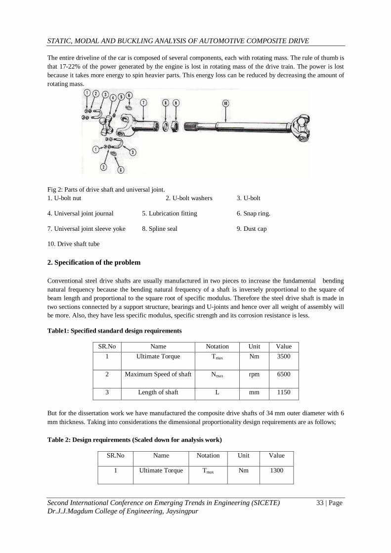
The entire driveline of the car is composed of several components, each with rotating mass. The rule of thumb is
that 17-22% of the power generated by the engine is lost in rotating mass of the drive train. The power is lost
because it takes more energy to spin heavier parts. This energy loss can be reduced by decreasing the amount of
rotating mass.
Fig 2: Parts of drive shaft and universal joint.
1. U-bolt nut 2. U-bolt washers 3. U-bolt
4. Universal joint journal 5. Lubrication fitting 6. Snap ring.
7. Universal joint sleeve yoke 8. Spline seal 9. Dust cap
10. Drive shaft tube
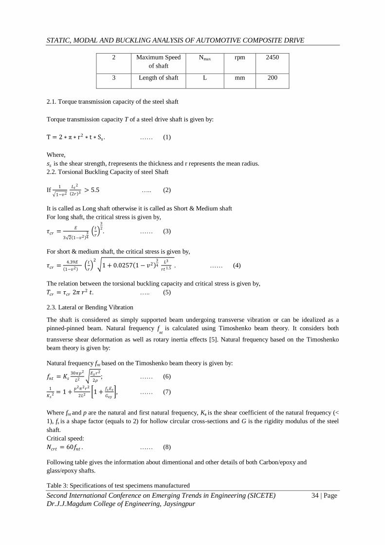
2. Specification of the problem
Conventional steel drive shafts are usually manufactured in two pieces to increase the fundamental bending
natural frequency because the bending natural frequency of a shaft is inversely proportional to the square of
beam length and proportional to the square root of specific modulus. Therefore the steel drive shaft is made in
two sections connected by a support structure, bearings and U-joints and hence over all weight of assembly will
be more. Also, they have less specific modulus, specific strength and its corrosion resistance is less.
Table1: Specified standard design requirements
SR.No Name Notation Unit Value
1 Ultimate Torque
Tmax Nm 3500
2 Maximum Speed of shaft Nmax rpm 6500
3 Length of shaft L mm 1150
But for the dissertation work we have manufactured the composite drive shafts of 34 mm outer diameter with 6
mm thickness. Taking into considerations the dimensional proportionality design requirements are as follows;
Table 2: Design requirements (Scaled down for analysis work)
SR.No Name Notation Unit Value
1 Ultimate Torque
Tmax Nm 1300
STATIC, MODAL AND BUCKLING ANALYSIS OF AUTOMOTIVE COMPOSITE DRIVE
Second International Conference on Emerging Trends in Engineering (SICETE) 34 | Page
Dr.J.J.Magdum College of Engineering, Jaysingpur
2 Maximum Speed
of shaft
Nmax rpm 2450
3 Length of shaft L mm 200
2.1. Torque transmission capacity of the steel shaft
Torque transmission capacity T of a steel drive shaft is given by:
T = 2 ∗ π ∗ r2 ∗ t ∗ Ss . …… (1)
Where,
𝑠𝑠 is the shear strength, 𝑡represents the thickness and r represents the mean radius.
2.2. Torsional Buckling Capacity of steel Shaft
If 1
1−𝑣2 𝐿𝑡
2
2𝑟 3 > 5.5 ….. (2)
It is called as Long shaft otherwise it is called as Short & Medium shaft
For long shaft, the critical stress is given by,
𝜏𝑐𝑟 =𝐸
3 2 1−𝑣2 34
𝑡
𝑟
3
2. …… (3)
For short & medium shaft, the critical stress is given by,
𝜏𝑐𝑟 =4.39𝐸
1−𝑣2
𝑡
𝑟
2 1 + 0.0257 1 − 𝑣2
3
4 𝐿3
𝑟𝑡 1.5 . …… (4)
The relation between the torsional buckling capacity and critical stress is given by,
𝑇𝑐𝑟 = 𝜏𝑐𝑟 2𝜋 𝑟2 𝑡. ….. (5)
2.3. Lateral or Bending Vibration
The shaft is considered as simply supported beam undergoing transverse vibration or can be idealized as a
pinned-pinned beam. Natural frequency fnt
is calculated using Timoshenko beam theory. It considers both
transverse shear deformation as well as rotary inertia effects [5]. Natural frequency based on the Timoshenko
beam theory is given by:
Natural frequency fnt based on the Timoshenko beam theory is given by:
𝑓𝑛𝑡 = 𝐾𝑠30𝜋𝑝2
𝐿2 𝐸𝑥𝑟
2
2𝜌; …… (6)
1
𝐾𝑠2 = 1 +
𝑝2𝜋2𝑟2
2𝐿2 1 +
𝑓𝑠𝐸𝑠
𝐺𝑥𝑦 , …… (7)
Where fnt and p are the natural and first natural frequency, Ks is the shear coefficient of the natural frequency (<
1), fs is a shape factor (equals to 2) for hollow circular cross-sections and G is the rigidity modulus of the steel
shaft.
Critical speed:
𝑁𝑐𝑟𝑡 = 60𝑓𝑛𝑡 . …… (8)
Following table gives the information about dimentional and other details of both Carbon/epoxy and
glass/epoxy shafts.
Table 3: Specifications of test specimens manufactured
STATIC, MODAL AND BUCKLING ANALYSIS OF AUTOMOTIVE COMPOSITE DRIVE
Second International Conference on Emerging Trends in Engineering (SICETE) 35 | Page
Dr.J.J.Magdum College of Engineering, Jaysingpur
Specifications Glass-Carbon/Epoxy Shaft Carbon/Epoxy Shaft
Inner Diameter(di) 20mm 22mm
Outer Diameter(do) 34mm 34mm
Length(l) 200mm 200mm
Thickness(t) 6mm-7mm 6mm
3. Finite Element Analysis
Finite Element Analysis (FEA) is a computer-based numerical technique for calculating the strength
and behavior of engineering structures. It can be used to calculate deflection, stress, vibration, buckling behavior
and many other phenomena. It also can be used to analyze either small or large- scale deflection under loading
or applied displacement. It uses a numerical technique called the finite element method (FEM). The primary
unknowns in this structural analysis are displacements and other quantities, such as strains, stresses, and reaction
forces, are then derived from the nodal displacements.
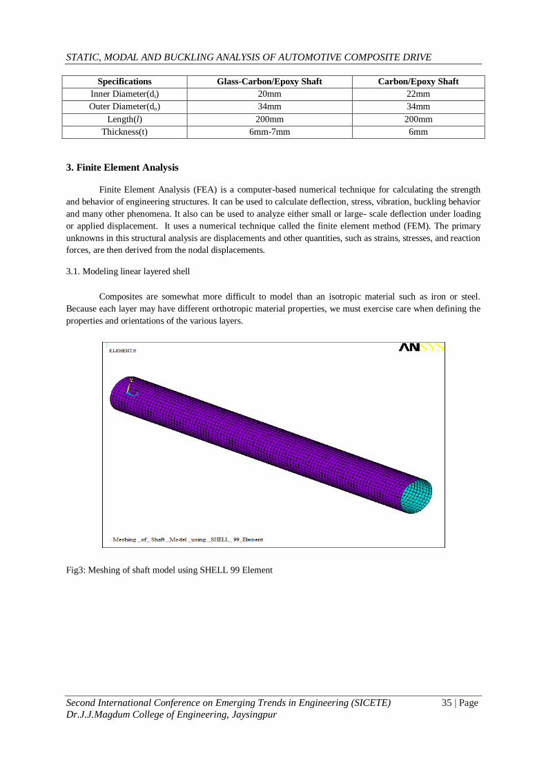
3.1. Modeling linear layered shell
Composites are somewhat more difficult to model than an isotropic material such as iron or steel.
Because each layer may have different orthotropic material properties, we must exercise care when defining the
properties and orientations of the various layers.
Fig3: Meshing of shaft model using SHELL 99 Element
STATIC, MODAL AND BUCKLING ANALYSIS OF AUTOMOTIVE COMPOSITE DRIVE
Second International Conference on Emerging Trends in Engineering (SICETE) 36 | Page
Dr.J.J.Magdum College of Engineering, Jaysingpur
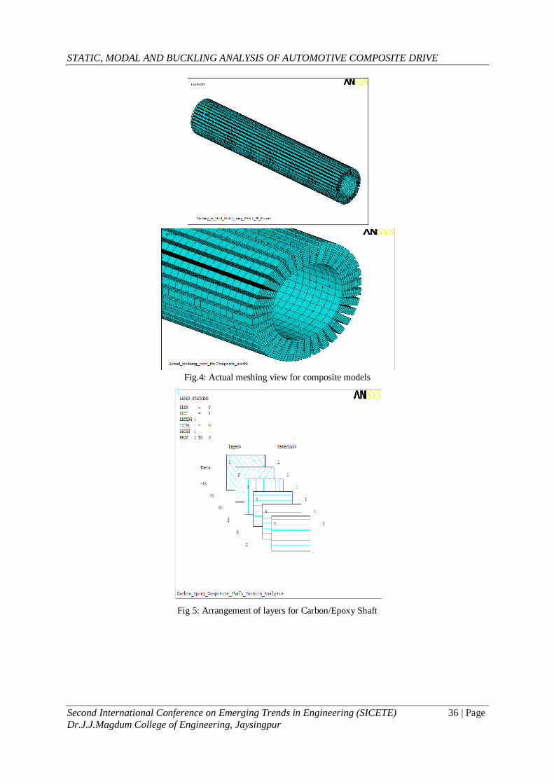
Fig.4: Actual meshing view for composite models
Fig 5: Arrangement of layers for Carbon/Epoxy Shaft
STATIC, MODAL AND BUCKLING ANALYSIS OF AUTOMOTIVE COMPOSITE DRIVE
Second International Conference on Emerging Trends in Engineering (SICETE) 37 | Page
Dr.J.J.Magdum College of Engineering, Jaysingpur
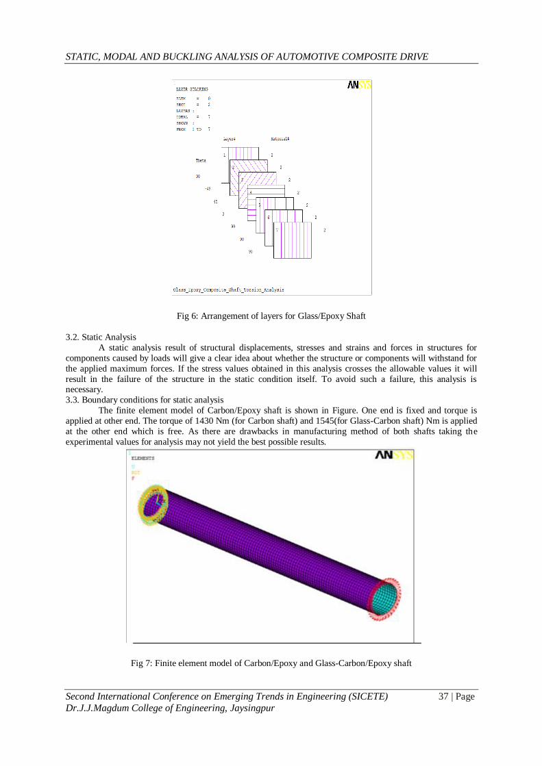
Fig 6: Arrangement of layers for Glass/Epoxy Shaft
3.2. Static Analysis
A static analysis result of structural displacements, stresses and strains and forces in structures for
components caused by loads will give a clear idea about whether the structure or components will withstand for
the applied maximum forces. If the stress values obtained in this analysis crosses the allowable values it will
result in the failure of the structure in the static condition itself. To avoid such a failure, this analysis is necessary.
3.3. Boundary conditions for static analysis
The finite element model of Carbon/Epoxy shaft is shown in Figure. One end is fixed and torque is
applied at other end. The torque of 1430 Nm (for Carbon shaft) and 1545(for Glass-Carbon shaft) Nm is applied
at the other end which is free. As there are drawbacks in manufacturing method of both shafts taking the
experimental values for analysis may not yield the best possible results.
Fig 7: Finite element model of Carbon/Epoxy and Glass-Carbon/Epoxy shaft
STATIC, MODAL AND BUCKLING ANALYSIS OF AUTOMOTIVE COMPOSITE DRIVE
Second International Conference on Emerging Trends in Engineering (SICETE) 38 | Page
Dr.J.J.Magdum College of Engineering, Jaysingpur
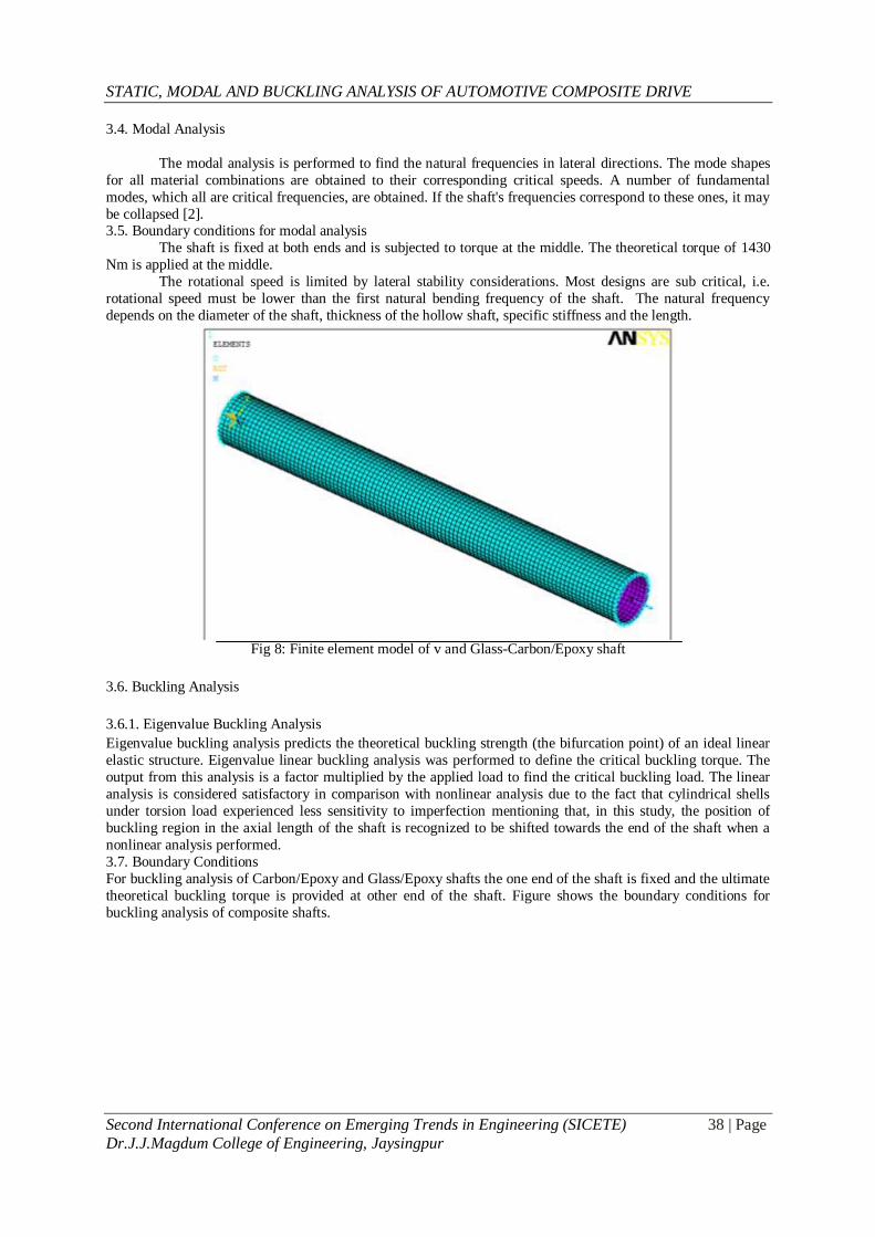
3.4. Modal Analysis
The modal analysis is performed to find the natural frequencies in lateral directions. The mode shapes
for all material combinations are obtained to their corresponding critical speeds. A number of fundamental
modes, which all are critical frequencies, are obtained. If the shaft's frequencies correspond to these ones, it may
be collapsed [2]. 3.5. Boundary conditions for modal analysis
The shaft is fixed at both ends and is subjected to torque at the middle. The theoretical torque of 1430
Nm is applied at the middle.
The rotational speed is limited by lateral stability considerations. Most designs are sub critical, i.e.
rotational speed must be lower than the first natural bending frequency of the shaft. The natural frequency
depends on the diameter of the shaft, thickness of the hollow shaft, specific stiffness and the length.
Fig 8: Finite element model of v and Glass-Carbon/Epoxy shaft
3.6. Buckling Analysis
3.6.1. Eigenvalue Buckling Analysis
Eigenvalue buckling analysis predicts the theoretical buckling strength (the bifurcation point) of an ideal linear
elastic structure. Eigenvalue linear buckling analysis was performed to define the critical buckling torque. The
output from this analysis is a factor multiplied by the applied load to find the critical buckling load. The linear
analysis is considered satisfactory in comparison with nonlinear analysis due to the fact that cylindrical shells
under torsion load experienced less sensitivity to imperfection mentioning that, in this study, the position of
buckling region in the axial length of the shaft is recognized to be shifted towards the end of the shaft when a
nonlinear analysis performed.
3.7. Boundary Conditions
For buckling analysis of Carbon/Epoxy and Glass/Epoxy shafts the one end of the shaft is fixed and the ultimate
theoretical buckling torque is provided at other end of the shaft. Figure shows the boundary conditions for
buckling analysis of composite shafts.

STATIC, MODAL AND BUCKLING ANALYSIS OF AUTOMOTIVE COMPOSITE DRIVE
Second International Conference on Emerging Trends in Engineering (SICETE) 39 | Page
Dr.J.J.Magdum College of Engineering, Jaysingpur
Fig 9: Finite element model of Carbon and Glass- Carbon/epoxy shaft for buckling analysis
4. Results 4.1. Static Analysis
The static, modal and buckling analysis is done to identify variations of stresses along the boundaries and in the
internal structure of drive shafts.
Displacement of carbon/epoxy shaft at application of torque:
Fig. 10: : Static Mode shape and Displacement of carbon/epoxy shaft at application of torque
Fig. 11: Static Mode shape and Displacement of Glass-carbon/epoxy shaft at application of torque
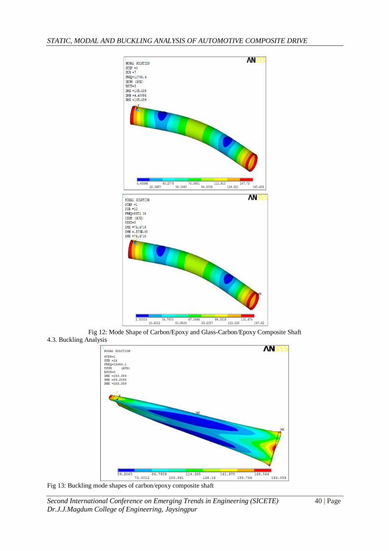
4.2. Modal Analysis
STATIC, MODAL AND BUCKLING ANALYSIS OF AUTOMOTIVE COMPOSITE DRIVE
Second International Conference on Emerging Trends in Engineering (SICETE) 40 | Page
Dr.J.J.Magdum College of Engineering, Jaysingpur
Fig 12: Mode Shape of Carbon/Epoxy and Glass-Carbon/Epoxy Composite Shaft
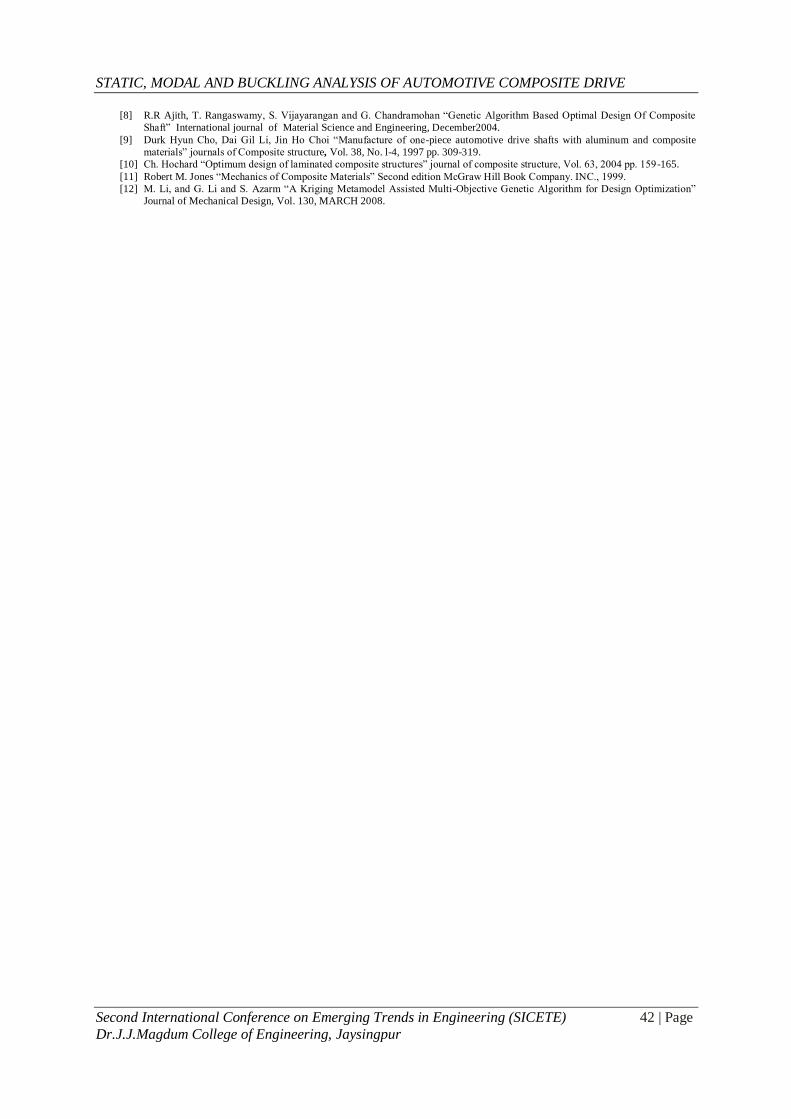
4.3. Buckling Analysis
Fig 13: Buckling mode shapes of carbon/epoxy composite shaft

STATIC, MODAL AND BUCKLING ANALYSIS OF AUTOMOTIVE COMPOSITE DRIVE
Second International Conference on Emerging Trends in Engineering (SICETE) 41 | Page
Dr.J.J.Magdum College of Engineering, Jaysingpur
Fig 14: buckling mode shapes of glass-carbon/epoxy composite shaft
4.4. Summarization of buckling analysis results
Table: Summarization of ANSYS results
Specimen Material Buckling Torque
obtained (Nm)
Displacement in static
analysis (mm)
Frequency obtained
in modal analysis
(Hz)
Carbon/Epoxy
2526.43
3.86
13454
Glass-Carbon/Epoxy
4145.54
9.53
7848
5. Conclusion
The results reveal that the orientation of fibers has great influence on the dynamic characteristics of the
composite material shafts in a positive direction.
Natural bending frequency of composite drive shaft is much higher than the steel drive shaft which
enhances the use of composite structures in higher mechanical operations involving severe vibration
conditions.
Analysis of both drive shaft shows that the composite drive shaft has capability to transmit more
torque, has more buckling torque transmission capability and has much higher fundamental natural
bending frequency which provides better margin of safety than the conventional two-piece composite
drive shaft.
“A two-piece steel drive shaft can be replaced by one-piece composite drive shaft removing all
unnecessary rotating parts; causing loss of inertia; resulting into definite 20% to 30% increase in fuel
efficiency”.
REFERENCES: [1] Dai Gil Lee and Hak Sung Kim “Design and manufacture of an automotive hybrid aluminum/composite drive shaft” journal of
composite structure, Vol 63, 2004 pp.87-99.
[2] M. A. Badie, A. Mahdi, and A. R. Abutalib “Automotive composite drive shafts: Investigation of the design variable effects”
International Journal of Engineering and Technology, Vol. 3, No.2, 2006, pp. 227-237.
[3] S A Mutasher, B B Sahari, A M S Hamouda, and S M Sapuan “Static and dynamic characteristics of a hybrid
aluminium/composite drive shaft” Journal of Materials Design and Applications, Vol .63, 2007 pp 221-235.
[4] Dr. Ammar Ali Hussein Al-filfily “Optimum Design of Composite Laminated Plate Using Genetic Algorithm and RSM”
Engineering and Technology Journal, Vol. 29, No. 5, 2011.
[5] Thimmegowda Rangaswamy, and Sabapathy Vijayarangan “Optimal Sizing and Stacking Sequence of Composite Drive Shafts”
journal of Material science, Vol.11, No.2, 2005.
[6] Zorica Dordevic, Stevan Maksimovic and Ivana Ilic “Dynamic Analysis of Hybrid Aluminum/Composite Shafts” Journal of
Scientific Technical Review, Vol.53, No.2, 2008.
[7] S. E Singh, H. B. H. Gubran and K. Gupta “Developments in Dynamics of Composite Material Shafts” International Journal of
Rotating Machinery, Vol. 3, No. 3, 1997 pp. 189-198
STATIC, MODAL AND BUCKLING ANALYSIS OF AUTOMOTIVE COMPOSITE DRIVE
Second International Conference on Emerging Trends in Engineering (SICETE) 42 | Page
Dr.J.J.Magdum College of Engineering, Jaysingpur
[8] R.R Ajith, T. Rangaswamy, S. Vijayarangan and G. Chandramohan “Genetic Algorithm Based Optimal Design Of Composite
Shaft” International journal of Material Science and Engineering, December2004.
[9] Durk Hyun Cho, Dai Gil Li, Jin Ho Choi “Manufacture of one-piece automotive drive shafts with aluminum and composite
materials” journals of Composite structure, Vol. 38, No. l-4, 1997 pp. 309-319.
[10] Ch. Hochard “Optimum design of laminated composite structures” journal of composite structure, Vol. 63, 2004 pp. 159-165.
[11] Robert M. Jones “Mechanics of Composite Materials” Second edition McGraw Hill Book Company. INC., 1999.
[12] M. Li, and G. Li and S. Azarm “A Kriging Metamodel Assisted Multi-Objective Genetic Algorithm for Design Optimization”
Journal of Mechanical Design, Vol. 130, MARCH 2008.