
STABILIZER BARS: Part 3. PRODUCTION...
10
TRANSPORT PROBLEMS 2011 PROBLEMY TRANSPORTU Volume 6 Issue 2 stabilizer bar, cold roll forming Adam-Markus WITTEK*, Hans-Christian RICHTER ThyssenKrupp Bilstein Suspension GmbH Oeger St. 85, 58095 Hagen, Germany Bogusław ŁAZARZ Silesian University of Technology, Faculty of Transport Krasińskiego St. 8, 40-019 Katowice, Poland *Corresponding author. E-mail: [email protected] STABILIZER BARS: Part 3. PRODUCTION METHODS Summary. The article outlines the methods of stabilizer bar production as well as selected issues concerning the theory of cold roll forming. A proper construction and the selection of parameters are fundamental factors influencing the selection of a suitable production process. The selection of the manufacturing process has a fundamental impact on the quality and durability of the stabilizer bars. STABILIZATORY SAMOCHODOWE: Część 3. METODY PRODUKCYJNE Streszczenie. W artykule przedstawiono metody produkcyjne stabilizatorów samochodowych oraz wybrane zagadnienia z teorii gięcia profili. Prawidłowa konstrukcja i właściwy dobór parametrów są podstawowymi czynnikami, które mają wpływ na wybranie odpowiedniej technologii produkcyjnej. Trafne określenie technologii wytwarzania ma zasadniczy wpływ na jakość i trwałość stabilizatorów. 1. INTRODUCTION While torsion bar springs at the end of prefabrication already have their final form and are hardened and tempered, the stabilizer bars often have to be bent in partly difficult shapes before the hardening process takes place. With the introduction of stabilizer bars in the 1930s, bending of these components was performed by targeted heating of planned bending points successively. Most commonly, two workmen worked together. One heated the point using a welding torch and the other drew the part, often with support, through a longer, tubular lever around an appropriate molded part. Shape forming began at the innermost bending of each side by turns. In the process, the simple molded bodies stuck in a horizontally lying steel plate with appropriate mounting holes for the molded part pins. The horizontal steel plate, which was situated approximately at the working height of the workmen, was given eventually the name „bending table“. After the production lines had come also in the stabilizer bar manufacturing, these bending tables were put mostly vertically while retaining the name and were furnished with numerous hydraulic cylinders for the bending tools (fig 1, 2) [3, 9]. The hot bended car stabilizer bars up to about 30 mm diameter got a separate bending table each, while the smaller batches of truck stabilizer bars, which had a diameter between 35 mm and 80 mm, were bent on a common bending table (fig. 3) [2, 3] with individually fitted tools. In case of car stabilizer bars, good fixing sufficed for correct positioning of the ends, while in case of the massive eyes of heavy truck stabilizer bars after removal from the bending table and before dipping into hardening oil a truing operation was performed [12].
-
Upload
truongtuong -
Category
Documents
-
view
226 -
download
2
Transcript of STABILIZER BARS: Part 3. PRODUCTION...

TRANSPORT PROBLEMS 2011 PROBLEMY TRANSPORTU Volume 6 Issue 2
stabilizer bar, cold roll forming
Adam-Markus WITTEK*, Hans-Christian RICHTER ThyssenKrupp Bilstein Suspension GmbH Oeger St. 85, 58095 Hagen, Germany Bogusław ŁAZARZ Silesian University of Technology, Faculty of Transport Krasińskiego St. 8, 40-019 Katowice, Poland *Corresponding author. E-mail: [email protected] STABILIZER BARS: Part 3. PRODUCTION METHODS
Summary. The article outlines the methods of stabilizer bar production as well as selected issues concerning the theory of cold roll forming. A proper construction and the selection of parameters are fundamental factors influencing the selection of a suitable production process. The selection of the manufacturing process has a fundamental impact on the quality and durability of the stabilizer bars.
STABILIZATORY SAMOCHODOWE: Część 3. METODY PRODUKCYJNE
Streszczenie. W artykule przedstawiono metody produkcyjne stabilizatorów samochodowych oraz wybrane zagadnienia z teorii gięcia profili. Prawidłowa konstrukcja i właściwy dobór parametrów są podstawowymi czynnikami, które mają wpływ na wybranie odpowiedniej technologii produkcyjnej. Trafne określenie technologii wytwarzania ma zasadniczy wpływ na jakość i trwałość stabilizatorów.
1. INTRODUCTION
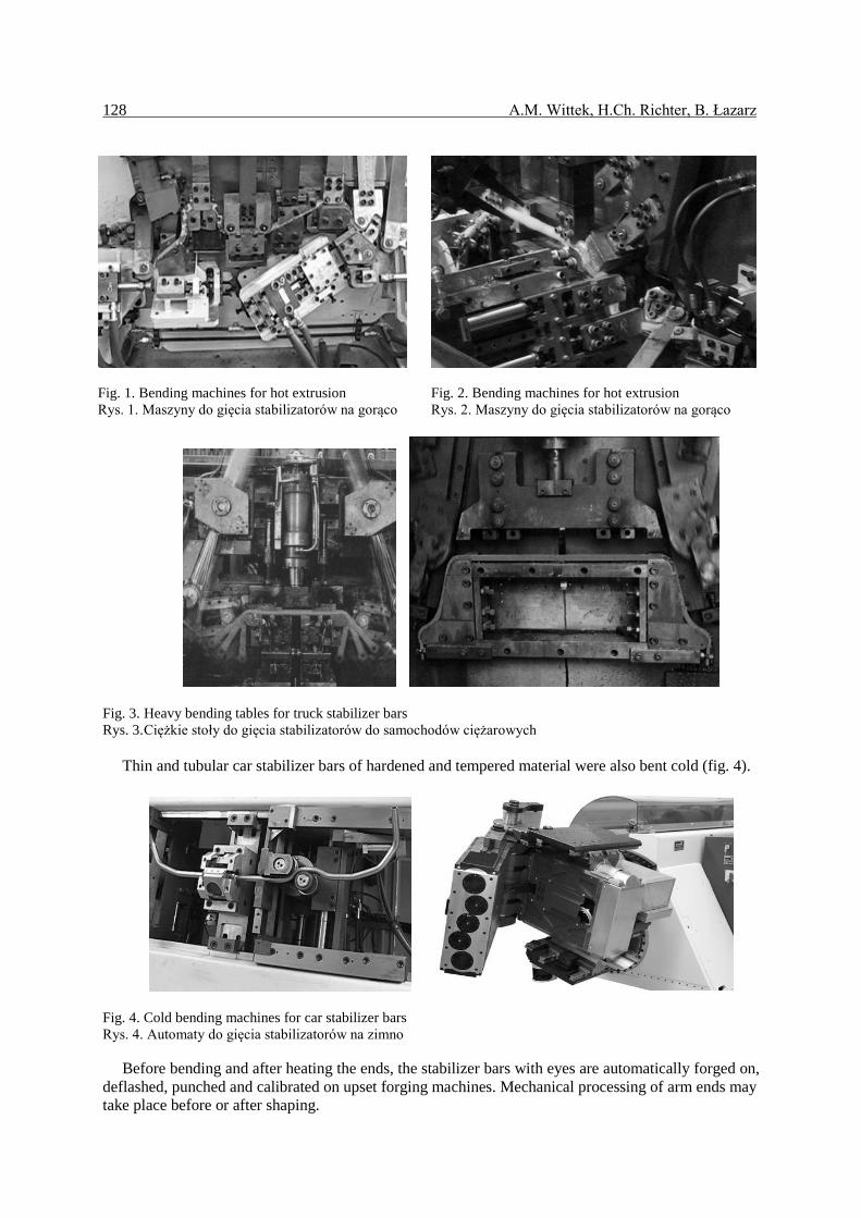
While torsion bar springs at the end of prefabrication already have their final form and are hardened and tempered, the stabilizer bars often have to be bent in partly difficult shapes before the hardening process takes place. With the introduction of stabilizer bars in the 1930s, bending of these components was performed by targeted heating of planned bending points successively. Most commonly, two workmen worked together. One heated the point using a welding torch and the other drew the part, often with support, through a longer, tubular lever around an appropriate molded part. Shape forming began at the innermost bending of each side by turns. In the process, the simple molded bodies stuck in a horizontally lying steel plate with appropriate mounting holes for the molded part pins. The horizontal steel plate, which was situated approximately at the working height of the workmen, was given eventually the name „bending table“. After the production lines had come also in the stabilizer bar manufacturing, these bending tables were put mostly vertically while retaining the name and were furnished with numerous hydraulic cylinders for the bending tools (fig 1, 2) [3, 9].
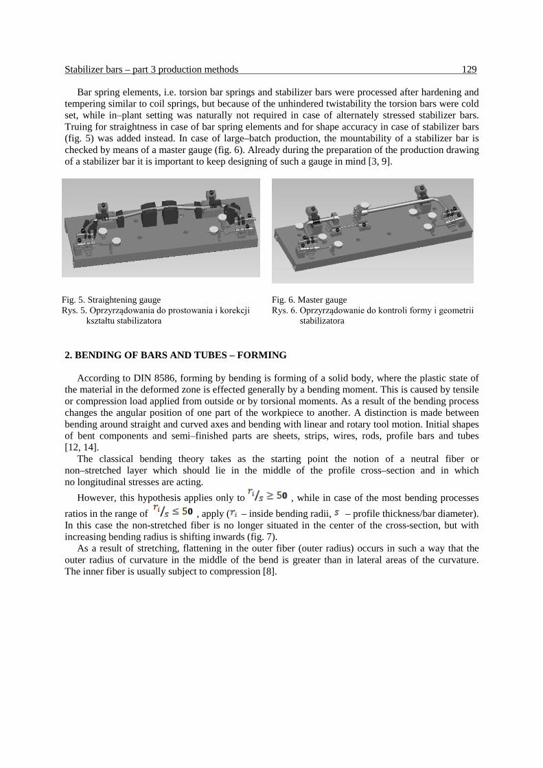
The hot bended car stabilizer bars up to about 30 mm diameter got a separate bending table each, while the smaller batches of truck stabilizer bars, which had a diameter between 35 mm and 80 mm, were bent on a common bending table (fig. 3) [2, 3] with individually fitted tools. In case of car stabilizer bars, good fixing sufficed for correct positioning of the ends, while in case of the massive eyes of heavy truck stabilizer bars after removal from the bending table and before dipping into hardening oil a truing operation was performed [12].
128 A.M. Wittek, H.Ch. Richter, B. Łazarz
Fig. 1. Bending machines for hot extrusion Rys. 1. Maszyny do gięcia stabilizatorów na gorąco
Fig. 2. Bending machines for hot extrusion Rys. 2. Maszyny do gięcia stabilizatorów na gorąco
Fig. 3. Heavy bending tables for truck stabilizer bars Rys. 3. Ciężkie stoły do gięcia stabilizatorów do samochodów ciężarowych
Thin and tubular car stabilizer bars of hardened and tempered material were also bent cold (fig. 4).
Fig. 4. Cold bending machines for car stabilizer bars Rys. 4. Automaty do gięcia stabilizatorów na zimno
Before bending and after heating the ends, the stabilizer bars with eyes are automatically forged on, deflashed, punched and calibrated on upset forging machines. Mechanical processing of arm ends may take place before or after shaping.
Stabilizer bars – part 3 production methods 129
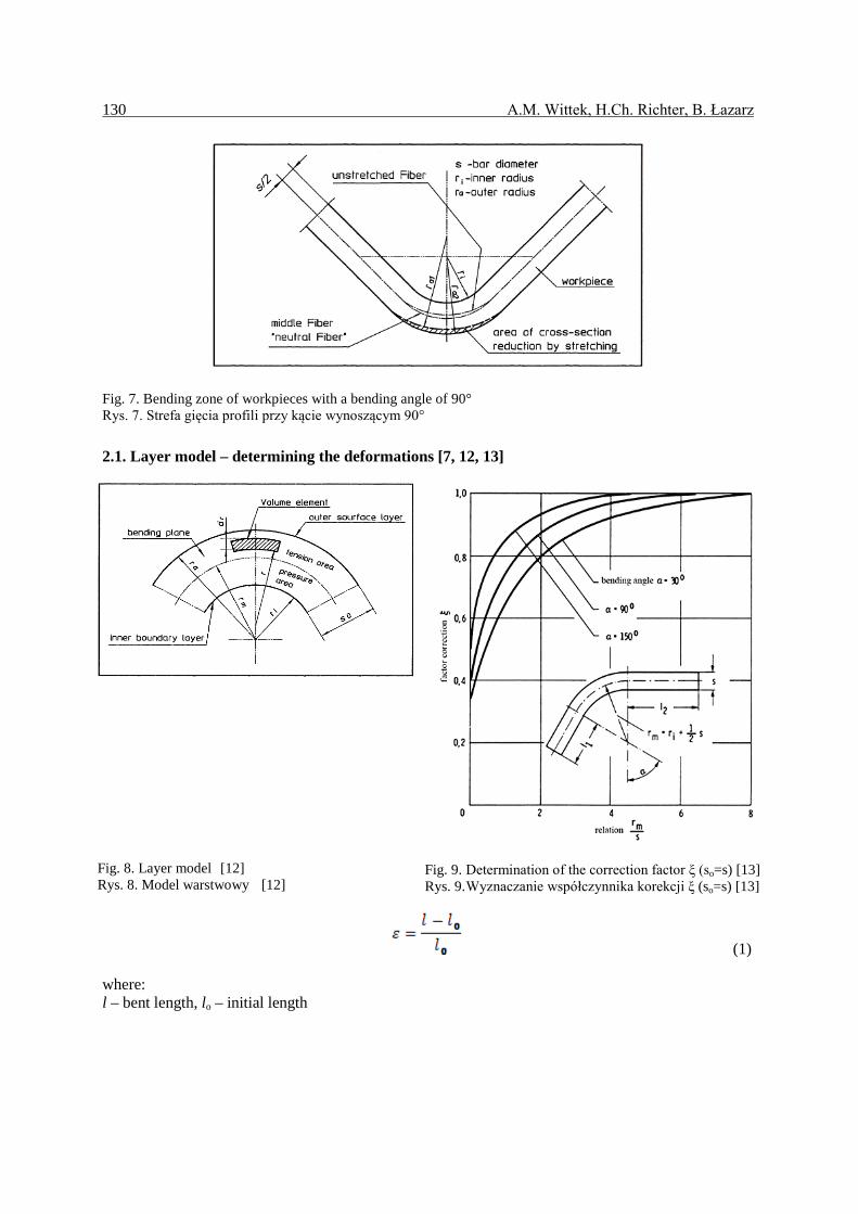
Bar spring elements, i.e. torsion bar springs and stabilizer bars were processed after hardening and tempering similar to coil springs, but because of the unhindered twistability the torsion bars were cold set, while in–plant setting was naturally not required in case of alternately stressed stabilizer bars. Truing for straightness in case of bar spring elements and for shape accuracy in case of stabilizer bars (fig. 5) was added instead. In case of large–batch production, the mountability of a stabilizer bar is checked by means of a master gauge (fig. 6). Already during the preparation of the production drawing of a stabilizer bar it is important to keep designing of such a gauge in mind [3, 9].
Fig. 5. Straightening gauge Rys. 5. Oprzyrządowania do prostowania i korekcji
kształtu stabilizatora
Fig. 6. Master gauge Rys. 6. Oprzyrządowanie do kontroli formy i geometrii
stabilizatora 2. BENDING OF BARS AND TUBES – FORMING
According to DIN 8586, forming by bending is forming of a solid body, where the plastic state of the material in the deformed zone is effected generally by a bending moment. This is caused by tensile or compression load applied from outside or by torsional moments. As a result of the bending process changes the angular position of one part of the workpiece to another. A distinction is made between bending around straight and curved axes and bending with linear and rotary tool motion. Initial shapes of bent components and semi–finished parts are sheets, strips, wires, rods, profile bars and tubes [12, 14].
The classical bending theory takes as the starting point the notion of a neutral fiber or non–stretched layer which should lie in the middle of the profile cross–section and in which no longitudinal stresses are acting.
However, this hypothesis applies only to , while in case of the most bending processes ratios in the range of , apply ( – inside bending radii, – profile thickness/bar diameter). In this case the non-stretched fiber is no longer situated in the center of the cross-section, but with increasing bending radius is shifting inwards (fig. 7).
As a result of stretching, flattening in the outer fiber (outer radius) occurs in such a way that the outer radius of curvature in the middle of the bend is greater than in lateral areas of the curvature. The inner fiber is usually subject to compression [8].
130 A.M. Wittek, H.Ch. Richter, B. Łazarz
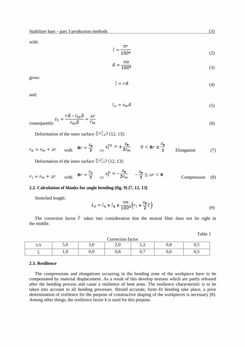
Fig. 7. Bending zone of workpieces with a bending angle of 90° Rys. 7. Strefa gięcia profili przy kącie wynoszącym 90° 2.1. Layer model – determining the deformations [7, 12, 13]
Fig. 8. Layer model [12] Rys. 8. Model warstwowy [12]
Fig. 9. Determination of the correction factor ξ (so=s) [13] Rys. 9. Wyznaczanie współczynnika korekcji ξ (so=s) [13]
(1)
where: l – bent length, lo – initial length
Stabilizer bars – part 3 production methods 131 with:
(2)
(3)
gives: (4)
and:
(5)
consequently: (6)
Deformation of the outer surface [12, 13]:
with ⇒ Elongation (7)
Deformation of the inner surface [12, 13]:
with ⇒ Compression (8) 2.2. Calculation of blanks for angle bending (fig. 9) [7, 12, 13]
Stretched length:
(9)
The correction factor takes into consideration that the neutral fiber does not lie right in the middle. Table 1
Correction factor ri/s 5,0 3,0 2,0 1,2 0,8 0,5 ξ 1,0 0,9 0,8 0,7 0,6 0,5
2.3. Resilience
The compressions and elongations occurring in the bending zone of the workpiece have to be compensated by material displacement. As a result of this develop stresses which are partly released after the bending process and cause a resilience of bent arms. The resilience characteristic is to be taken into account in all bending processes. Should accurate, form–fit bending take place, a prior determination of resilience for the purpose of constructive shaping of the workpieces is necessary [8]. Among other things, the resilience factor k is used for this purpose.
132 A.M. Wittek, H.Ch. Richter, B. Łazarz
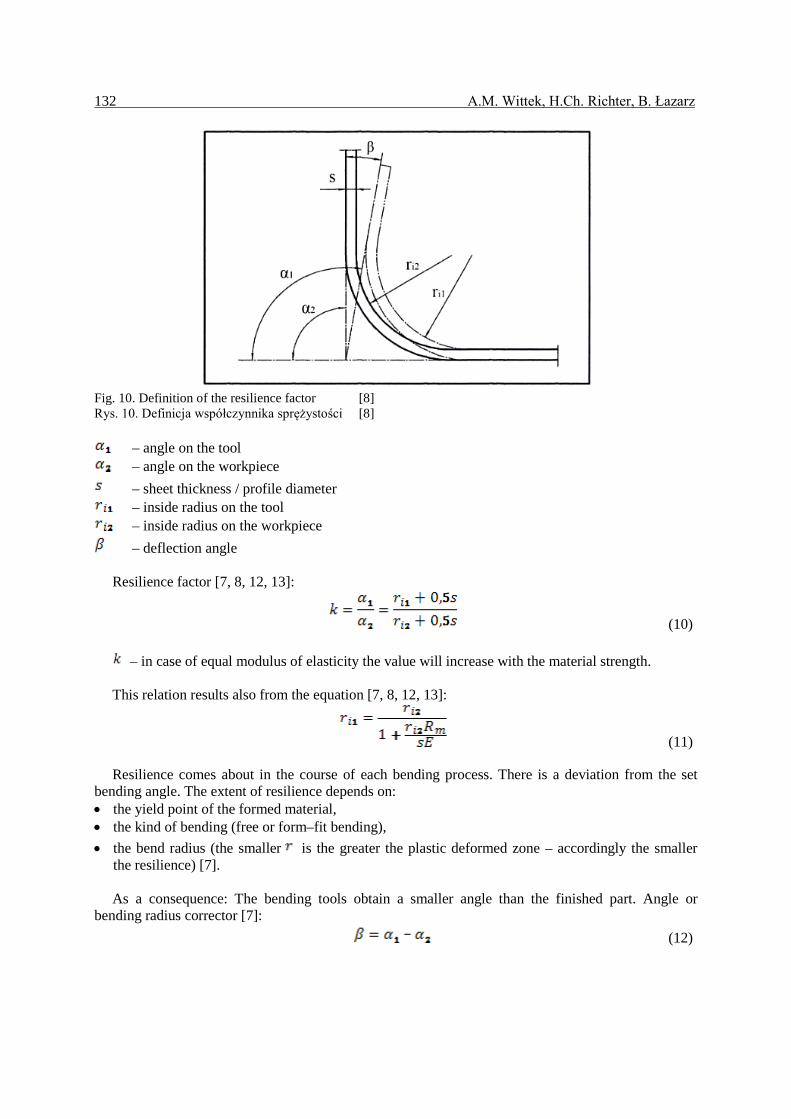
Fig. 10. Definition of the resilience factor [8] Rys. 10. Definicja współczynnika sprężystości [8]
– angle on the tool – angle on the workpiece
– sheet thickness / profile diameter – inside radius on the tool – inside radius on the workpiece
– deflection angle
Resilience factor [7, 8, 12, 13]:
(10)
– in case of equal modulus of elasticity the value will increase with the material strength.
This relation results also from the equation [7, 8, 12, 13]:
(11)
Resilience comes about in the course of each bending process. There is a deviation from the set bending angle. The extent of resilience depends on: • the yield point of the formed material, • the kind of bending (free or form–fit bending), • the bend radius (the smaller is the greater the plastic deformed zone – accordingly the smaller
the resilience) [7].
As a consequence: The bending tools obtain a smaller angle than the finished part. Angle or bending radius corrector [7]: (12)
Stabilizer bars – part 3 production methods 133
Table 2 Deflection angle for St to
and to β [°] 5 3 1
s [mm] 0,1 bis 0,7 0,8 bis 1,9 2 bis 4 ri [mm] 1*s bis 5*s 1*s bis 5*s 1*s bis 5*s
Reduction of resilience:
• Correction of the tool angle, • Resqueezing of the bending edge in a die, • Application of an increased embossing and bending momentum, • Bending at higher temperatures (hot bending),
• Decrease of the relative bending radius , • In principle by decreasing the resilient core zone.
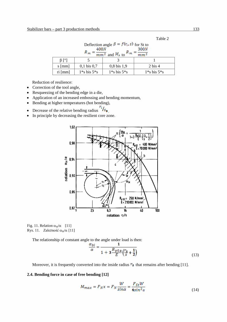
Fig. 11. Relation αbl/α [11] Rys. 11. Zależność αbl/α [11]
The relationship of constant angle to the angle under load is then:
(13)
Moreover, it is frequently converted into the inside radius that remains after bending [11]. 2.4. Bending force in case of free bending [12]
(14)

134 A.M. Wittek, H.Ch. Richter, B. Łazarz
Equation of outside with inside moment :
(15)
(16)
(at α = 90o) (17)
Bending force according to Mäkelt, Cali and Ohler [12]:
(18)
with:
for
for 2.5. Bending of a solid stabilizer bar
In order to avoid or to reduce all undesired side effects, such as: • Change of cross-section in the bending areas, • Resilience, • Unfavorable bending radii and bending planes, • Notches, damages in the bending areas, • Strength decrease.
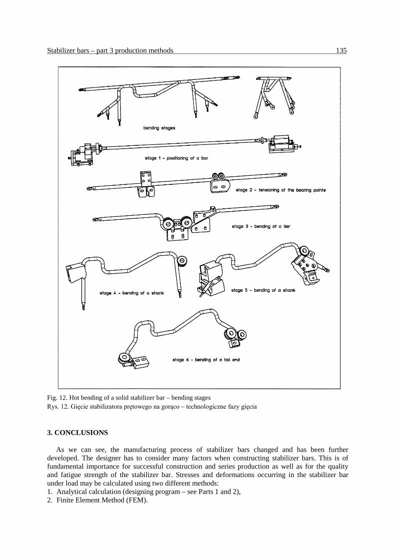
an appropriate, suitable bending method for each stabilizer bar has to be selected. The construction is thus connected with the design of bending tools. Fig. 10 shows bending stages of a solid stabilizer bar in a bending machine. The tool selection and shape takes the abovementioned side effects into consideration.
Stabilizer bars – part 3 production methods 135
Fig. 12. Hot bending of a solid stabilizer bar – bending stages Rys. 12. Gięcie stabilizatora prętowego na gorąco – technologiczne fazy gięcia 3. CONCLUSIONS
As we can see, the manufacturing process of stabilizer bars changed and has been further developed. The designer has to consider many factors when constructing stabilizer bars. This is of fundamental importance for successful construction and series production as well as for the quality and fatigue strength of the stabilizer bar. Stresses and deformations occurring in the stabilizer bar under load may be calculated using two different methods: 1. Analytical calculation (designing program – see Parts 1 and 2), 2. Finite Element Method (FEM).
136 A.M. Wittek, H.Ch. Richter, B. Łazarz
The first method serves as a standard tool for designing stabilizer bars: • exact solution in straight sections, • consideration of excessive stresses (bend) by means of influencing factors, • small parameterization effort, only central fibers and cross-section are described, • Very fast calculation.
The second method is used for the detailed analysis of critical cases.
References 1. von Estorff H.-E.:Technische Daten Fahrzeugfedern Teil:3 Stabilisatoren. Stahlwerke
Brüninghaus GmbH, Werk Werdohl, Hang Druck KG, Köln, 1969. 2. Ulbricht J., Vondracek H., Kindermann S.; Warm geformte Federn – Leitfaden für Konstruktion
und Fertigung. Hoesch Werke, Hohenlimburg Schwerte AG, W. Stumpf KG, Bochum, 1973. 3. Fischer F., H.Vondracek H.: Warm geformte Federn - Konstruktion und Fertigung. Hoesch
Werke, Hoesch Hohenlimburg AG, W.Stumpf KG, Bochum, 1987. 4. Meissner M.,.Schorcht H.-J.: Metallfedern – Grundlagen, Werkstoffe, Berechnung, Gestaltung
und Rechnereinsatz. 2. Auflage, Springer Verlag, Ilmenau, 2007. 5. Muhs D., Wittel H., Jannasch D., Voßiek J.: Roloff / Matek Maschinenelemente – Normung,
Berechnung, Gestaltung. 18. Auflage, Viewegs Fachbücher der Technik, Wiesbaden, 2007. 6. Jakubowicz A. Orloś Z.: Wytrzymałość materiałów. Wydanie 6, Wydawnictwa Naukowo-
Techniczne, Warszawa, 1984. 7. Tschätsch H., Dietrich J.: Praxis der Umformtechnik. 9. Auflage, Vieweg + Teubner,
Wiesbaden, 2008. 8. Klocke F., W.König W.: Fertigungsverfahren 4 – Umformen. 5. Auflage, Springer Verlag.
Berlin – Heidelberg, 2006. 9. Meissner M., Fischer F., Wanke K., Plitzko M.: Die Geschichte der Metallfedern und
Federtechnik in Deutschland. 1. Auflage, Universitätsverlag Ilmenau. Ilmenau, 2009. 10. Engel B.: Biegen von Rohren. 4 Internationale Konferenz Hydroumformung, Institut für
Fertigungstechnik, Lehrstuhl für Umformtechnik, Universität Siegen, 25. Oktober, 2005. 11. Engel B.: Rückfederung – Phänomen und plastomechanische Beschreibung. DGM Fortbildungs-
seminar Tiefziehen, Institut für Fertigungstechnik, Lehrstuhl für Umformtechnik, Universität Siegen, 12. – 13, April, 2005.
12. Hardtmann A.: Vorlesung Fertigungstechnik I – Umformtechnik. Technische Universität, Dresden, Institut für Produktionstechnik Professur für Umform- und Urformtechnik, Dresden Dezember, 2003.
13. Grüning K.: Umformtechnik. 4. Auflage, Vieweg Verlag. Braunschweig, 1986. 14. DIN 8586: Fertigungsverfahren Biegeumformen – Einordnung, Unterteilung, Begriffe. Normen-
ausschuss Technische Grundlagen (NATG), September, 2003. Received 30.05.2010; accepted in revised form 15.06.2011